US8690418B2 - Method of mixing - Google Patents
Method of mixingDownload PDFInfo
- Publication number
- US8690418B2 US8690418B2US12/921,412US92141209AUS8690418B2US 8690418 B2US8690418 B2US 8690418B2US 92141209 AUS92141209 AUS 92141209AUS 8690418 B2US8690418 B2US 8690418B2
- Authority
- US
- United States
- Prior art keywords
- flexible container
- mixing
- shaft
- vessel
- container
- Prior art date
- Legal status (The legal status is an assumption and is not a legal conclusion. Google has not performed a legal analysis and makes no representation as to the accuracy of the status listed.)
- Active, expires
Links
Images


Classifications
- B—PERFORMING OPERATIONS; TRANSPORTING
- B01—PHYSICAL OR CHEMICAL PROCESSES OR APPARATUS IN GENERAL
- B01F—MIXING, e.g. DISSOLVING, EMULSIFYING OR DISPERSING
- B01F23/00—Mixing according to the phases to be mixed, e.g. dispersing or emulsifying
- B01F23/20—Mixing gases with liquids
- B01F23/23—Mixing gases with liquids by introducing gases into liquid media, e.g. for producing aerated liquids
- B01F23/231—Mixing gases with liquids by introducing gases into liquid media, e.g. for producing aerated liquids by bubbling
- B01F23/23105—Arrangement or manipulation of the gas bubbling devices
- B01F23/2312—Diffusers
- B01F23/23124—Diffusers consisting of flexible porous or perforated material, e.g. fabric
- B—PERFORMING OPERATIONS; TRANSPORTING
- B01—PHYSICAL OR CHEMICAL PROCESSES OR APPARATUS IN GENERAL
- B01F—MIXING, e.g. DISSOLVING, EMULSIFYING OR DISPERSING
- B01F27/00—Mixers with rotary stirring devices in fixed receptacles; Kneaders
- B01F27/05—Stirrers
- B01F27/11—Stirrers characterised by the configuration of the stirrers
- B01F27/19—Stirrers with two or more mixing elements mounted in sequence on the same axis
- B01F27/191—Stirrers with two or more mixing elements mounted in sequence on the same axis with similar elements
- B—PERFORMING OPERATIONS; TRANSPORTING
- B01—PHYSICAL OR CHEMICAL PROCESSES OR APPARATUS IN GENERAL
- B01F—MIXING, e.g. DISSOLVING, EMULSIFYING OR DISPERSING
- B01F27/00—Mixers with rotary stirring devices in fixed receptacles; Kneaders
- B01F27/21—Mixers with rotary stirring devices in fixed receptacles; Kneaders characterised by their rotating shafts
- B01F27/2121—Mixers with rotary stirring devices in fixed receptacles; Kneaders characterised by their rotating shafts composed of interconnected parts
- B—PERFORMING OPERATIONS; TRANSPORTING
- B01—PHYSICAL OR CHEMICAL PROCESSES OR APPARATUS IN GENERAL
- B01F—MIXING, e.g. DISSOLVING, EMULSIFYING OR DISPERSING
- B01F27/00—Mixers with rotary stirring devices in fixed receptacles; Kneaders
- B01F27/80—Mixers with rotary stirring devices in fixed receptacles; Kneaders with stirrers rotating about a substantially vertical axis
- B01F27/88—Mixers with rotary stirring devices in fixed receptacles; Kneaders with stirrers rotating about a substantially vertical axis with a separate receptacle-stirrer unit that is adapted to be coupled to a drive mechanism
- B—PERFORMING OPERATIONS; TRANSPORTING
- B01—PHYSICAL OR CHEMICAL PROCESSES OR APPARATUS IN GENERAL
- B01F—MIXING, e.g. DISSOLVING, EMULSIFYING OR DISPERSING
- B01F27/00—Mixers with rotary stirring devices in fixed receptacles; Kneaders
- B01F27/80—Mixers with rotary stirring devices in fixed receptacles; Kneaders with stirrers rotating about a substantially vertical axis
- B01F27/91—Mixers with rotary stirring devices in fixed receptacles; Kneaders with stirrers rotating about a substantially vertical axis with propellers
- B—PERFORMING OPERATIONS; TRANSPORTING
- B01—PHYSICAL OR CHEMICAL PROCESSES OR APPARATUS IN GENERAL
- B01F—MIXING, e.g. DISSOLVING, EMULSIFYING OR DISPERSING
- B01F33/00—Other mixers; Mixing plants; Combinations of mixers
- B01F33/45—Magnetic mixers; Mixers with magnetically driven stirrers
- B01F33/453—Magnetic mixers; Mixers with magnetically driven stirrers using supported or suspended stirring elements
- B01F33/4535—Magnetic mixers; Mixers with magnetically driven stirrers using supported or suspended stirring elements using a stud for supporting the stirring element
- B—PERFORMING OPERATIONS; TRANSPORTING
- B01—PHYSICAL OR CHEMICAL PROCESSES OR APPARATUS IN GENERAL
- B01F—MIXING, e.g. DISSOLVING, EMULSIFYING OR DISPERSING
- B01F35/00—Accessories for mixers; Auxiliary operations or auxiliary devices; Parts or details of general application
- B01F35/10—Maintenance of mixers
- B01F35/145—Washing or cleaning mixers not provided for in other groups in this subclass; Inhibiting build-up of material on machine parts using other means
- B01F35/146—Working under sterile conditions; Sterilizing the mixer or parts thereof
- B—PERFORMING OPERATIONS; TRANSPORTING
- B01—PHYSICAL OR CHEMICAL PROCESSES OR APPARATUS IN GENERAL
- B01F—MIXING, e.g. DISSOLVING, EMULSIFYING OR DISPERSING
- B01F35/00—Accessories for mixers; Auxiliary operations or auxiliary devices; Parts or details of general application
- B01F35/20—Measuring; Control or regulation
- B01F35/22—Control or regulation
- B01F35/221—Control or regulation of operational parameters, e.g. level of material in the mixer, temperature or pressure
- B01F35/2215—Temperature
- B—PERFORMING OPERATIONS; TRANSPORTING
- B01—PHYSICAL OR CHEMICAL PROCESSES OR APPARATUS IN GENERAL
- B01F—MIXING, e.g. DISSOLVING, EMULSIFYING OR DISPERSING
- B01F35/00—Accessories for mixers; Auxiliary operations or auxiliary devices; Parts or details of general application
- B01F35/40—Mounting or supporting mixing devices or receptacles; Clamping or holding arrangements therefor
- B01F35/41—Mounting or supporting stirrer shafts or stirrer units on receptacles
- B01F35/412—Mounting or supporting stirrer shafts or stirrer units on receptacles by supporting both extremities of the shaft
- B01F35/4121—Mounting or supporting stirrer shafts or stirrer units on receptacles by supporting both extremities of the shaft at the top and at the bottom of the receptacle, e.g. for performing a conical orbital movement about a vertical axis
- B—PERFORMING OPERATIONS; TRANSPORTING
- B01—PHYSICAL OR CHEMICAL PROCESSES OR APPARATUS IN GENERAL
- B01F—MIXING, e.g. DISSOLVING, EMULSIFYING OR DISPERSING
- B01F35/00—Accessories for mixers; Auxiliary operations or auxiliary devices; Parts or details of general application
- B01F35/50—Mixing receptacles
- B01F35/51—Mixing receptacles characterised by their material
- B—PERFORMING OPERATIONS; TRANSPORTING
- B01—PHYSICAL OR CHEMICAL PROCESSES OR APPARATUS IN GENERAL
- B01F—MIXING, e.g. DISSOLVING, EMULSIFYING OR DISPERSING
- B01F35/00—Accessories for mixers; Auxiliary operations or auxiliary devices; Parts or details of general application
- B01F35/50—Mixing receptacles
- B01F35/513—Flexible receptacles, e.g. bags supported by rigid containers
- B—PERFORMING OPERATIONS; TRANSPORTING
- B01—PHYSICAL OR CHEMICAL PROCESSES OR APPARATUS IN GENERAL
- B01F—MIXING, e.g. DISSOLVING, EMULSIFYING OR DISPERSING
- B01F35/00—Accessories for mixers; Auxiliary operations or auxiliary devices; Parts or details of general application
- B01F35/90—Heating or cooling systems
- B01F35/92—Heating or cooling systems for heating the outside of the receptacle, e.g. heated jackets or burners
- C—CHEMISTRY; METALLURGY
- C12—BIOCHEMISTRY; BEER; SPIRITS; WINE; VINEGAR; MICROBIOLOGY; ENZYMOLOGY; MUTATION OR GENETIC ENGINEERING
- C12M—APPARATUS FOR ENZYMOLOGY OR MICROBIOLOGY; APPARATUS FOR CULTURING MICROORGANISMS FOR PRODUCING BIOMASS, FOR GROWING CELLS OR FOR OBTAINING FERMENTATION OR METABOLIC PRODUCTS, i.e. BIOREACTORS OR FERMENTERS
- C12M23/00—Constructional details, e.g. recesses, hinges
- C12M23/26—Constructional details, e.g. recesses, hinges flexible
- C—CHEMISTRY; METALLURGY
- C12—BIOCHEMISTRY; BEER; SPIRITS; WINE; VINEGAR; MICROBIOLOGY; ENZYMOLOGY; MUTATION OR GENETIC ENGINEERING
- C12M—APPARATUS FOR ENZYMOLOGY OR MICROBIOLOGY; APPARATUS FOR CULTURING MICROORGANISMS FOR PRODUCING BIOMASS, FOR GROWING CELLS OR FOR OBTAINING FERMENTATION OR METABOLIC PRODUCTS, i.e. BIOREACTORS OR FERMENTERS
- C12M27/00—Means for mixing, agitating or circulating fluids in the vessel
- C12M27/02—Stirrer or mobile mixing elements
- C—CHEMISTRY; METALLURGY
- C12—BIOCHEMISTRY; BEER; SPIRITS; WINE; VINEGAR; MICROBIOLOGY; ENZYMOLOGY; MUTATION OR GENETIC ENGINEERING
- C12M—APPARATUS FOR ENZYMOLOGY OR MICROBIOLOGY; APPARATUS FOR CULTURING MICROORGANISMS FOR PRODUCING BIOMASS, FOR GROWING CELLS OR FOR OBTAINING FERMENTATION OR METABOLIC PRODUCTS, i.e. BIOREACTORS OR FERMENTERS
- C12M29/00—Means for introduction, extraction or recirculation of materials, e.g. pumps
- C12M29/06—Nozzles; Sprayers; Spargers; Diffusers
- B—PERFORMING OPERATIONS; TRANSPORTING
- B01—PHYSICAL OR CHEMICAL PROCESSES OR APPARATUS IN GENERAL
- B01F—MIXING, e.g. DISSOLVING, EMULSIFYING OR DISPERSING
- B01F35/00—Accessories for mixers; Auxiliary operations or auxiliary devices; Parts or details of general application
- B01F35/90—Heating or cooling systems
- B01F2035/99—Heating
- B—PERFORMING OPERATIONS; TRANSPORTING
- B01—PHYSICAL OR CHEMICAL PROCESSES OR APPARATUS IN GENERAL
- B01F—MIXING, e.g. DISSOLVING, EMULSIFYING OR DISPERSING
- B01F2101/00—Mixing characterised by the nature of the mixed materials or by the application field
- B01F2101/44—Mixing of ingredients for microbiology, enzymology, in vitro culture or genetic manipulation
- B—PERFORMING OPERATIONS; TRANSPORTING
- B01—PHYSICAL OR CHEMICAL PROCESSES OR APPARATUS IN GENERAL
- B01F—MIXING, e.g. DISSOLVING, EMULSIFYING OR DISPERSING
- B01F23/00—Mixing according to the phases to be mixed, e.g. dispersing or emulsifying
- B01F23/20—Mixing gases with liquids
- B01F23/23—Mixing gases with liquids by introducing gases into liquid media, e.g. for producing aerated liquids
- B01F23/231—Mixing gases with liquids by introducing gases into liquid media, e.g. for producing aerated liquids by bubbling
- B01F23/23105—Arrangement or manipulation of the gas bubbling devices
- B01F23/2312—Diffusers
- B01F23/23123—Diffusers consisting of rigid porous or perforated material
- B01F23/231231—Diffusers consisting of rigid porous or perforated material the outlets being in the form of perforations
- B—PERFORMING OPERATIONS; TRANSPORTING
- B01—PHYSICAL OR CHEMICAL PROCESSES OR APPARATUS IN GENERAL
- B01F—MIXING, e.g. DISSOLVING, EMULSIFYING OR DISPERSING
- B01F23/00—Mixing according to the phases to be mixed, e.g. dispersing or emulsifying
- B01F23/20—Mixing gases with liquids
- B01F23/23—Mixing gases with liquids by introducing gases into liquid media, e.g. for producing aerated liquids
- B01F23/231—Mixing gases with liquids by introducing gases into liquid media, e.g. for producing aerated liquids by bubbling
- B01F23/23105—Arrangement or manipulation of the gas bubbling devices
- B01F23/2312—Diffusers
- B01F23/23126—Diffusers characterised by the shape of the diffuser element
- B01F23/231266—Diffusers characterised by the shape of the diffuser element being in the form of rings or annular elements
- B—PERFORMING OPERATIONS; TRANSPORTING
- B01—PHYSICAL OR CHEMICAL PROCESSES OR APPARATUS IN GENERAL
- B01F—MIXING, e.g. DISSOLVING, EMULSIFYING OR DISPERSING
- B01F23/00—Mixing according to the phases to be mixed, e.g. dispersing or emulsifying
- B01F23/20—Mixing gases with liquids
- B01F23/23—Mixing gases with liquids by introducing gases into liquid media, e.g. for producing aerated liquids
- B01F23/237—Mixing gases with liquids by introducing gases into liquid media, e.g. for producing aerated liquids characterised by the physical or chemical properties of gases or vapours introduced in the liquid media
- B01F23/2376—Mixing gases with liquids by introducing gases into liquid media, e.g. for producing aerated liquids characterised by the physical or chemical properties of gases or vapours introduced in the liquid media characterised by the gas being introduced
- B01F23/23761—Aerating, i.e. introducing oxygen containing gas in liquids
- B01F23/237612—Oxygen
- B—PERFORMING OPERATIONS; TRANSPORTING
- B01—PHYSICAL OR CHEMICAL PROCESSES OR APPARATUS IN GENERAL
- B01F—MIXING, e.g. DISSOLVING, EMULSIFYING OR DISPERSING
- B01F23/00—Mixing according to the phases to be mixed, e.g. dispersing or emulsifying
- B01F23/20—Mixing gases with liquids
- B01F23/23—Mixing gases with liquids by introducing gases into liquid media, e.g. for producing aerated liquids
- B01F23/237—Mixing gases with liquids by introducing gases into liquid media, e.g. for producing aerated liquids characterised by the physical or chemical properties of gases or vapours introduced in the liquid media
- B01F23/2376—Mixing gases with liquids by introducing gases into liquid media, e.g. for producing aerated liquids characterised by the physical or chemical properties of gases or vapours introduced in the liquid media characterised by the gas being introduced
- B01F23/23762—Carbon dioxide
- B—PERFORMING OPERATIONS; TRANSPORTING
- B01—PHYSICAL OR CHEMICAL PROCESSES OR APPARATUS IN GENERAL
- B01F—MIXING, e.g. DISSOLVING, EMULSIFYING OR DISPERSING
- B01F35/00—Accessories for mixers; Auxiliary operations or auxiliary devices; Parts or details of general application
- B01F35/20—Measuring; Control or regulation
- B01F35/21—Measuring
Definitions
- the present inventionrelates to the field of mixing, preferably in a disposable mixing vessel and, more particularly, to a method of mixing in a disposable mixing vessel having self-contained, magnetically coupled mixing apparatus included within the mixing vessel as a unit.
- Agitator or mixing tanks with rotating agitator apparatusare typically used to mix chemical compounds. Frequently, the ingredients being mixed in the agitator tanks require a sterile environment, such as when ingredients are being mixed to prepare a pharmaceutical product. Although some applications do not require a sterile environment, the United States Food and Drug Administration has set out strict sterile requirements for some solutions. To provide such a sterile environment, mixing tanks must be constructed to prevent contaminants from entering the tank during the entire batch process, including filling the tank, mixing and draining the tank.
- the use of magnetic drives for driving the agitator apparatushas been known for a long time, since such drives do not require a physical connection or seals between moving parts of the drive means and the agitator apparatus in the sterile environment.
- the agitator apparatus within the tankincludes a magnetic element near the bottom of the agitator tank, which is engaged by a corresponding magnetic element on a drive motor positioned outside the tank. Activation of the drive motor having the corresponding magnetic element positioned adjacent the magnetic element of the agitator apparatus causes the agitator apparatus to rotate within the agitator tank.
- sterile agitator tankshave been developed that utilize a flexible vessel as the mixing container.
- the flexible vesselscan be constructed in a sterile environment and sealed prior to use.
- Such systemswhich use a tank support to maintain the integrity of the flexible container when filled, generally are disposed of after use, to obviate the need for cleaning so as to recreate a sterile environment in the vessel between uses.
- the ability to control the sterile environmentis greatly improved.
- agitator tanks for use in sterile applicationsare known to include the agitator apparatus within the sealed vessel when shipped.
- the sterile agitator apparatusis placed within the sterile vessel prior to sealing, minimizing the potential for breaching the sterile environment.
- agitator tanks with magnetically driven internal fluid agitating apparatusexamples include U.S. Pat. Nos. 4,209,259; 4,993,841; and 5,470,152, Japanese Patent No. JP 56-045752 and Published PCT Application No. PCT/US02/31478. Each of these references describes agitator tanks with agitating apparatus having driven magnetic elements that are engaged by adjacent cooperating drive magnetic elements associated with a drive means.
- U.S. Pat. No. 5,470,152describes an agitator tank with a drive housing into which the drive magnet is inserted.
- An impeller having a magnetic elementis attached to the drive housing with the magnetic element having magnets oriented vertically, so that the magnets are parallel with the longitudinal axis of the drive housing containing the cooperating magnetic element of the drive motor.
- the impelleris removably attached to the bottom portion of the drive housing with a clip.
- U.S. Pat. Nos. 4,209,259 and 4,993,841describe mixing vessels with magnetically driven agitator apparatus, in the form of impellers mounted on posts in the vessels.
- Each of these referencesdescribe the agitator apparatus as located within the vessel in an area related to a flange or recess that positions the impeller with respect to the drive means.
- the impellers of these referencesmerely reside in the vessel at a single location on a post, and can be removed by pulling on a ring on the terminal end of the agitator apparatus.
- the device of PCT Application No. PCT/US02/31478utilizes an impeller that is received by a post located on a rigid portion of the mixing vessel.
- the remaining portion of the mixing vesselis called out as being a flexible portion, described in the reference as a bag.
- the impellerhas a magnetic element that is driven by an external drive motor having a magnetic drive element.
- Japanese Patent No. JP 56-045752is directed to a magnetically driven stirring device having a rotating circular plate on ball bearings fixed to the bottom of the vessel, where the magnetic element of the agitator apparatus is associated with the bottom of the vessel.
- the agitator apparatus of this referenceis formed of a metal alloy for wear purposes.
- None of the prior art referencesdescribes a method of mixing using a sterile sealed single use mixing vessel including a centrally disposed shaft, attached to the top and bottom portions of the vessel and utilizing radial or thrust bearings, such as slide bearings, ball bearings, journal bearings, or roller bearings, to facilitate rotation of the shaft, on which one or more impellers are mounted.
- radial or thrust bearingssuch as slide bearings, ball bearings, journal bearings, or roller bearings
- none of the prior art referencesdescribes a method of mixing using a sterile sealed single use mixing vessel comprising a flexible bag including a centrally disposed shaft, which is attached to the top and bottom portions of the vessel, has one or more impellers, is foldable or may be assembled from sections, whereby the impeller(s) are positioned at a predetermined level. Assembling the centrally disposed shaft may be accomplished from the outside of the mixing vessel by a manual manipulation of the user.
- the present inventionis directed to a method of mixing including providing a flexible container which comprises at least two components, assembling the components from outside the flexible container to form a centrally disposed magnetic driven shaft with at least one impeller, whereby the integrity of the flexible container is maintained, filling the flexible container having the centrally disposed magnetic driven shaft with one or more ingredients of the contents to be mixed; engaging a magnetic element of the centrally disposed magnetic driven shaft with an external magnetic drive element; analyzing the contents of the flexible container using at least one of a sensor or a sampling line on the flexible container; and draining the contents of the flexible container through a drain port at the bottom of the flexible container.
- the inventionwill be carried out in a single use mixing vessel
- the flexible containerhaving a centrally disposed shaft with a magnetic element at one end and one or more impellers mounted thereon, the shaft being associated with top and bottom flanges with radial or thrust bearings, such as slide bearings, ball bearings, journal bearings, or roller bearings, therebetween for facilitating rotation of the shaft, the bottom flange including a drain port with access to the interior of the vessel for draining the vessel.
- the drain porthas a barbed tip, where the tip flares down to a lesser diameter at the terminal end for receiving a harvest line tube.
- the mixing vesselpreferably also includes one or more inlets for filling the vessel with the materials to be mixed and, optionally, one or more sensors and/or sampling lines for measuring properties of the material in the vessel and/or removing a portion of the material in the vessel for analysis.
- the mixing vesselalso includes a sparger for introducing gases into the mixture.
- the present mixing vesselincludes a gas inlet and gas exhaust as well as an internal sparging line to direct the gas to the sparger, which is preferably located at the bottom of the mixing vessel about at least a portion of the bottom flange with which the bottom of the shaft is associated.
- the sparger linepreferably enters the vessel at the top portion and is attached to a side wall, bringing the gas to the sparger at the bottom of the vessel, either through the use of bands or straps that are preferably formed of the material of the interior of the vessel, or as a sleeve of the material attached along the side wall of the vessel.
- the mixing vesselis constructed so as to create a sterile environment within the vessel, including all of the component parts therein.
- the mixing vesselcan be evacuated of unnecessary gases, hermetically sealed and packed to improve shipping and storage at a facility where the vessel is to be used.
- the preferred embodiment describedrelates to a sterile environment for mixing materials, there may be circumstances where a sterile environment is not necessary for the mixture and a non-sterile environment is acceptable. Therefore, the present invention is not limited to the maintenance of a sterile environment in the mixing vessel.
- packing for shipping and storagemay be improved through the use of a sectioned, foldable or telescopic shaft, thus reducing the size of the mixing vessel prior to use.
- Such an embodimentis especially preferred when the mixing vessel is intended for large volume applications.
- the vesselmay be formed in any suitable geometry, size or shape, however, it is preferably constructed to have a cylindrical shape with substantially hemispherical top and bottom. In this regard, it is intended that the vessel will be placed into a rigid or semi-rigid tank generally conforming to the geometry, size and/or shape of the vessel for structural integrity prior to, during and after filling with the materials to be mixed.
- manufacturing methods for the vesselmay vary, depending on the shape desired and the tolerances sustainable.
- the flexible containercan be operated up to volumes of more than 100 liters without separate outer stabilizing apparatuses.
- the reason for thisis the double mounting of both ends of the central shaft on both a first and a second flange.
- this constructionmakes it possible to mix media with higher density and viscosity. This is particularly advantageous when using the mixing container as a bioreactor. It was found that intensive stirring could be maintained even toward the end of a cultivation procedure, where the cell density has very much increased.
- this constructionmakes it possible to operate the central shaft using a plurality of mixing elements, which can be used for more intensive mixing of the container contents and hence for shorter operating times.
- the use according to the invention of one or more spargersfurther promotes the stirring by a type of gas/air lifting effect and, when operated as a bioreactor, the simultaneous supply of a culture solution with the required gasses is ensured.
- the inlets and outlets of the flexible containerare equipped with aseptic connectors and a drain port, which is preferably integrated in the flange, installed at the bottom of the container.
- the mixing containercan be used not only once, but also for a number of successive or even continuous mixing and culture processes without needing to reequip said container, which could endanger the sterile conditions.
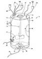
- FIG. 1is a perspective view of the preferred embodiment of the mixing vessel of the present invention.
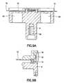
- FIG. 2Ais a perspective view of a first embodiment of a bottom flange for use as part of the mixing vessel of the present invention.
- FIG. 2Bis a perspective view of a second embodiment of a bottom flange for use as part of the mixing vessel of the present invention.
- FIG. 2Cis a perspective view of a third embodiment of a bottom flange for use as part of the mixing vessel of the present invention.
- FIG. 3Ais a perspective view of a portion of a sectioned shaft for use in the mixing vessel of the present invention.
- FIG. 3Bis a perspective view of a portion of a telescopic shaft for use in the mixing vessel of the present invention.
- FIG. 3Cis a perspective view of a portion of a first embodiment of a jointed shaft for use in the mixing vessel of the present invention.
- FIG. 3Dis a perspective view of a portion of a second embodiment of a jointed shaft for use in the mixing vessel of the present invention.
- FIG. 3Eis a perspective view of a portion of a third embodiment of a jointed shaft for use in the mixing vessel of the present invention.
- FIG. 4is a perspective view of a portion of a jointed shaft for use in the mixing vessel of the present invention with an impeller mounted thereon.
- FIG. 5is a perspective view of a preferred sparger with a tubular feed line for use in the mixing vessel of the present invention.
- FIG. 6is a perspective view of a sparger with a sleeve feed line for use in the mixing vessel of the present invention.
- FIG. 7Ais a perspective view of a first embodiment of the flexible portion of the mixing container of the present invention.
- FIG. 7Bis a plan view of a first embodiment of the flexible portion of the mixing container of the present invention in the folded and open configurations.
- FIG. 8Ais a perspective view of a second embodiment of the flexible portion of the mixing container of the present invention.
- FIG. 8Bis an elevational view of a second embodiment of the flexible portion of the mixing container of the present invention in its open configuration.
- FIG. 8Cis an elevational view of a second embodiment of the flexible portion of the mixing container of the present invention in its folded configuration.
- FIG. 9Ais a schematic cross section of the top flange and magnetic element of the shaft of the present invention.
- FIG. 9Bis a cross section of a portion of a preferred connection between the top flange and the magnetic element of the shaft of the present invention.
- FIG. 10is a partial cross section of a preferred embodiment of the present invention.
- FIG. 11Ais a partial cross section of the area of the top flange plate of the preferred embodiment of the present invention shown in FIG. 10 .
- FIG. 11Bis a partial cross section of the area of the bottom flange plate of the preferred embodiment of the present invention shown in FIG. 10 .
- FIG. 12is an alternative embodiment of the flexible vessel of the present invention with two spargers.
- FIG. 13is a partial cross section of the flexible vessel shown in a rigid or semi-rigid tank of generally the same geometry, size and shape to maintain the integrity of the flexible container.
- FIG. 14is a perspective view of another preferred embodiment of the mixing vessel of the present invention in a partially collapsed configuration, prior to full assembly of the shaft and filling with the material to be mixed.
- the disposable mixing vessel 2 of the present inventioncomprises a flexible container 4 having a centrally disposed shaft 6 with a magnetic element 8 at one end and one or more impellers 10 mounted thereon.
- the shaft 6is associated with top and bottom flanges 12 and 14 on the vessel 2 , and includes thrust bearings 74 between the shaft 6 and one or both of the flanges 12 and 14 for facilitating rotation of the shaft 6 .
- the top flange 12preferably includes a drive coupling 15 for receiving the magnetic drive element of a drive motor (not shown).
- the bottom flange 14includes a drain port 18 with access to the interior of the vessel 2 for draining the vessel 2 , preferably using a harvest line 20 attached to the drain port 18 , after the mixing process has been completed.
- the mixing vessel 2includes one or more inlets 22 for filling the vessel 2 with the materials to be mixed. It is preferred that the vessel 2 incorporates one or more sensors 24 across the flexible container 4 , for measuring various properties of the materials being mixed in the vessel 2 , and/or sampling lines 26 , for removing a sample of the material in the vessel 2 for analysis. Preferably, the sensors 24 and sampling lines 26 are located in the bottom third of the mixing vessel 2 .
- the mixing vessel 2 shown in FIG. 1includes a sparger 28 for introducing gases into the mixture.
- a gas inlet 30is preferably located on the top portion 32 of the flexible container 4 .
- the gas inlet 30can be any fitting through which gas can pass to a sparger line 36 on the interior of the vessel 2 , which feeds the sparger 28 preferably located at the bottom of the vessel 2 .
- the sparger 28is attached to the bottom portion 34 of the container 4 about the bottom flange 14 to improve mixture of the gas with the materials being mixed in the vessel 2 .
- One or more gas exhausts 38permits the gas that has not been mixed into the materials in the vessel 2 to be removed from the vessel 2 , preferably for recycle into the gas inlet 30 as necessary.
- the sparger line 36is preferably a tube or a sleeve that is attached to a side wall 40 of the container 4 to keep the sparger line 36 from interfering with the rotating shaft 6 and the one or more impellers 10 mounted on the rotating shaft 6 .
- the sparger line 36 or sleeve 36 ′ and sparger 28can be attached to the flexible container 4 by any means, preferably including welding, adhesives or bands or straps 42 that keep the sparger line 36 and sparger 28 properly located within the container 4 .
- the bottom flange 14 associated with the bottom of the shaft 6 and forming part of the vessel 2is more particularly shown in FIGS. 2A-2C , where several embodiments are illustrated.
- Each of the bottom flange 14 embodimentsare formed of a substantially rigid material, preferably a rigid plastic, and include a flange plate 44 that is connected to the flexible container 4 in the center of the bottom portion 34 .
- the flange plate 44can be connected to the flexible container 4 in any known way that creates a hermetic seal between the rigid and flexible materials.
- the upper portion of the bottom flange 14which is maintained in the interior of the vessel 2 , includes a mating member 46 which engages the bottom of the centrally disposed shaft 6 .
- the mating member 46can be either a male member 46 as shown in FIGS. 2A and 2B , which is inserted into an opening at the bottom of the shaft 6 (not shown), or a female member 46 ′ into which the bottom terminal end of the shaft 6 is inserted. It is preferred that the shaft 6 fit on the mating member 46 with a minimal friction, so that the shaft 6 can freely rotate on the mating member 46 , including the possible inclusion of a thrust bearing (not shown) between the shaft 6 and the mating member 46 . If desired, a catch (not shown) that does not significantly impair rotation of the shaft 6 on the mating member 46 can be used to secure the shaft 6 to the mating member 46 .
- the bottom flange 14also includes a drain port 18 .
- the drain port 18is associated with apertures 48 on the interior portion of the bottom flange 14 for access to the interior of the vessel 2 and removal of the mixture from the vessel 2 after the batch has been fully mixed.
- the drain port 18preferably has a barbed tip 50 for receiving the harvest line 20 .
- the barbed tip 50flares down to a lesser external diameter at the terminal end to facilitate connection of the harvest line 20 and preferably includes a shelf 52 which assists in keeping the harvest line 20 from slipping off of the drain port 18 .
- the present inventioncontemplates a shaft 6 that is included in sections within the shipped and/or stored vessel that must be assembled during preparation for receiving the materials to be mixed. This will especially aid in large volume applications of the present technology.
- FIG. 3Ashows components which are represented by sections 54 of a shaft 6 that have corresponding threaded ends 56 and 58 where the sections 54 can be screwed together to create the shaft 6 .
- the sections 54further include a threaded terminal end 56 for receiving the magnetic element 8 that makes up the top of the shaft 6 , as more fully described below.
- the sections 54 with threaded terminal ends 56can be incorporated as separate parts in a space-saving fashion in the flexible container 4 which may be folded flat during shipping.
- the sections 54can be manually assembled from outside of the flexible container 4 before starting operation of the flexible container 4 in order to create the ready-to-use shaft 6 without disrupting the sterility of the optionally presterilized flexible container 4 .
- a usermay assemble these sections 54 with the preferably flexible walls 40 of the container 4 serving as a sterile barrier between the sections 54 to be manually assembled in the container 4 and the environment, so that the sterility of the interior of the flexible container 4 is maintained.
- a spring catch 60is most preferred.
- the spring catch 60can use a living hinge with a detent end or a spring pushing a ball outward on the interior section 54 , with the detent or ball engaging a receiving hole on the exterior section 54 ′, as suitable constructions.
- the first section 54can be slidably stored inside the second section 54 ′ in a space saving fashion in the flexible container 4 which may be folded flat during shipping.
- the sections 54can be extended from outside the flexible container 4 , like a telescope, before starting operation of the flexible container 4 in order to create the ready-to-use telescopic shaft 6 without disrupting the sterility of the optionally presterilized flexible container 4 .
- a usermay manually extend these telescopic sections 54 , 54 ′ with the preferably flexible walls 40 of the container 4 serving as a sterile barrier between the sections 54 , 54 ′ to be manually assembled in the container 4 and the environment, so that the sterility of the interior of the flexible container 4 is maintained.
- the shaft 6comprising a plurality of segments 54 , 54 ′ which can be latched into one another via the device 60 , it is possible to increase the length of the shaft 6 during the mixing process in a number of steps without interrupting the sterility limit, so that the shaft length is also automatically adapted to the increased mixing container volume in a manner analogous to an upscale process in the case where the volume in the flexible container 4 is increased sequentially and in a number of steps.
- each segment 54can have an impeller 10 with respectively one collar 64 which can be displaced along the segment 54 and which, by means of the adjacent segment 54 ′, can be locked with the larger diameter adjacent to the device 60 in the telescopically extended state of the shaft 6 .
- sectioned shafts 6include the use of hinges 62 that can be manipulated from a folded position to an open position, examples of which are shown in FIGS. 3C-3E .
- hinges 62that can be manipulated from a folded position to an open position
- FIGS. 3C-3EOther alternatives for sectioned shafts 6 include the use of hinges 62 that can be manipulated from a folded position to an open position, examples of which are shown in FIGS. 3C-3E .
- These examplesinclude a hinge 62 , shown in FIG. 3C , that pivots in a single plane, as well as flexible elastic hinges 62 ′, shown in FIGS. 3D and 3E , that pivot in a variety of planes.
- the sections 54can be maintained in an open configuration through the use of locking hinges, which are lockable in a wide variety of known ways, or by the use of a sleeve 64 that covers the hinge 62 to prevent pivoting.
- locking hingeswhich are lockable in a wide variety
- the impeller 10is formed with a sleeve 64 for sliding on the shaft 6 to the area covering the hinge 62 to prevent the hinge 62 from pivoting.
- a locking mechanism(not shown) locks the sleeve 64 of the impeller 10 in place over the hinge 62 to ensure that the hinge 62 is maintained in the open configuration.
- the sectioned shaft 6can be folded flat in a space-saving fashion in the flexible container 4 which may be also folded flat during shipping. After shipping, the sectioned shaft 6 can be manually manipulated from outside the flexible container 4 from the folded position to the open position by use of the hinges 62 before starting operation of the flexible container 4 in order to create the ready-to-use unfolded, sectioned shaft 6 .
- a usermay unfold the sectioned shaft 6 via the preferably flexible walls 40 of the flexible container 4 which serve as a sterile barrier ensuring the maintenance of the sterility of the interior of the flexible container 4 .
- the sectioned shaft 6be constructed sterile and hermetically sealed in the mixing vessel 2 for shipping and storage, and that the sections 54 of the shaft 6 be assembled into the open configuration in the mixing vessel 2 without breaching the seal of the vessel 2 .
- FIG. 14shows one embodiment of the present invention, where the flexible container 4 has been folded flat in a space saving fashion for purposes of shipping and storage.
- the flexible container 4has a foldable shaft 6 which is transformed into its operation configuration by unfolding the flexible container 4 and manually manipulating the sections 54 of the foldable shaft 6 about the hinge 62 from a closed position to an open position from outside the bag without disrupting the integrity and sterility of the flexible container 4 .
- the impeller 10has one or more blades that are also foldable during shipping.
- the impeller 10may be positioned at a predetermined level on the shaft 6 and the blades of the impeller 10 may be unfolded in an analogous manner as during the assembly of the shaft 6 .
- the top of the shaft 6incorporates a magnetic element 8 , preferably including a plurality of magnets 66 , which is made part of the shaft 6 by any means of attachment or construction.
- the magnetic element 8 of the shaft 6is then positioned adjacent the top flange 12 of the vessel 2 .
- a preferred magnetic element 8 and top flange 12 arrangementis shown in FIGS. 9A and 9B , where the magnetic element 8 is connected to the top flange 12 so as to enable the magnetic drive means (not shown) to act upon the magnets 66 of the magnetic element across the top flange 12 .
- the magnetic element 8is fixed on the shaft 6 by screwing a threaded end 56 of the shaft 6 , as shown in FIG. 3A , into a threaded opening 68 within the magnetic element 8 .
- other meanssuch as keyed members, adhesives, clips, snaps, pins, screws, latches, welding, and the like, as well as forming the magnetic element 8 on the shaft 6 during construction of the shaft 6 , can be used to attach the magnetic element 8 to the shaft 6 , without limitation.
- the preferred embodiment of the present inventionincludes a hook or catch 70 on the magnetic element 8 that engages a lip 72 on the top flange 12 .
- the particular means for attaching the magnetic element 8 and the top flange 8is not essential, including not only the use of the catch 70 associated with the top flange 12 and the lip 72 associated with the magnetic element 8 , but alternatives such as snaps, channels and the like are contemplated, as long as the magnetic element 8 can rotate relatively freely in relation to the top flange 12 .
- the use of thrust bearings 74 between the magnetic element 8 and the top flange 12is contemplated.
- the top flange 12preferably includes a drive coupling 15 that extends upwardly from the exterior surface of the top flange 12 .
- the top flange 12is formed of a rigid material, including a rigid plate 76 for connection to the flexible container 4 with a hermetic seal.
- the sparger 28having holes 78 for releasing gas into the mixture, is more particularly shown in FIG. 5 .
- the sparger 28is preferably attached to the flexible container 4 with flexible straps 42 welded to the interior of the bottom portion 34 of the flexible container 4 .
- other means for attaching the sparger 28may be used, including adhesives, clips, and the like, however, welding straps 42 formed of the same material as the interior of the flexible container 4 to the interior of the flexible container 4 is most preferred.
- FIG. 6An alternative construction for the sparger line 36 is shown in FIG. 6 , which uses a sleeve 36 ′ as the sparger line.
- the sleeve 36is constructed of a length of material, preferably the same as the interior of the flexible container 4 , welded or otherwise affixed at the longitudinal sides to the interior of the flexible container 4 .
- the area between the sleeve 36 ′ and the flexible container 4carries the gas from the gas inlet 30 to the sparger 28 .
- the mixing vessel 2may have more than one sparger 28 .
- the mixing vessel 2may have two spargers 28 a and 28 b , as shown in FIG. 12 .
- different sparger lines 36 a and 36 bfed by different gas inlets 30 a and 30 b could be used.
- the different spargers 28 a and 28 bcan have different characteristics related to the type or volume of gas that is being introduced into the mixture. These different characteristics can include, but are not limited to the size and number of the holes (not shown). Additionally, the two spargers 28 a and 28 b can be incorporated into the mixing vessel 2 in any manner, with each being incorporated the same or different ways, as a manner of design choice.
- the sparger lines 36which lie on the wall 40 as protrusions which extend into the inside of the flexible container 4 , simultaneously act as flow breakers/baffles, which further increase the stirring of the mixing container contents in the flexible container 4 .
- the parallel arrangement of at least three and preferably four spargers 28 with equidistant spacing on the wall 40is particularly preferred in order to optimally use this flow breaking effect of the sparger lines 36 .
- the flexible container 4 of the mixing vessel 2can have any suitable shape, however, the shape must be determined with considerations to eliminating areas where flow of the materials may be reduced, folding the mixing vessel 2 for shipping and storage, and unfolding of the vessel 2 for use.
- FIGS. 7A , 7 B and 8 A- 8 Cshow various configurations of the flexible container 4 that are considered to be suitable for use with the present invention, without limitation.
- the shape of the flexible container 4is preferably hemispherical, allowing for more efficient mixing and sparging of its contents.
- the mixing vessel 2is preferably supported by a rigid or semi rigid container or tank 88 during filling, mixing and draining.
- the preferred tank 88is of generally the same geometry, shape and/or size as the flexible container 4 , and is preferably hemispherical, to minimize stress at seams or changes of direction in the material of the flexible container 4 (see FIG. 13 ).
- the tank 88would have one or more openings 90 , 90 a for inserting the empty mixing vessel 2 prior to use and accessing the various elements that need to be accessed during use of the mixing vessel 2 , including the drive means 15 , inlets 22 , exhaust 38 , sampling lines 26 , etc.
- the tank 88should have legs or a stand 92 to maintain the tank in an upright position while allowing access to the drain port 18 for draining the mixture through harvest line 20 .
- the top and/or bottom of the shaftis rotational by means of radial bearings, such as friction (sliding), journal, ball or roller bearings, and more preferably sliding bearings, similar to that shown in FIG. 9B .
- radial bearingssuch as friction (sliding), journal, ball or roller bearings, and more preferably sliding bearings, similar to that shown in FIG. 9B .
- FIGS. 10 , 11 A and 11 BA preferred commercial embodiment of the present invention is shown in FIGS. 10 , 11 A and 11 B.
- This embodimentincludes the elements described above, including the center shaft 6 having impellers 10 thereon, mounted on a top flange 12 and a bottom flange 14 that is hermetically sealed to a flexible container 4 .
- a sectioned shaft 6 , sparger 28 , material inlets 22 , gas inlet 30 and exhaust 38 , sensors 24 , sampling line 26 , harvest line 20 and the likeare envisioned for use with this embodiment, as desired and without limitation.
- the top flange 12shown in FIGS. 10 and 11A having a drive motor 80 positioned within the drive coupling 15 so as to orient the drive magnets 82 with the driven magnets 66 , includes a mating member 46 as described above with respect to the bottom flange 14 .
- the thrust bearings 74are preferably oriented vertically between the mating member 46 of the top flange 12 and the top of the shaft 6 .
- the magnet element 8 of this embodimentis preferably formed on the terminal end of the shaft 6 , so as to create an integral shaft 6 if desired.
- the bottom flange 14can include any acceptable mating member 46 with thrust bearings 74 located between the mating member 46 and a portion of the bottom of the shaft 6 .
- thisincludes a lower portion of the shaft 6 being formed as a receiver for the mating member 46 with the trust bearings 74 therebetween.
- the bottom flange 14can be formed with a female mating member 46 ′ which receives the shaft 6 , with the thrust bearings 74 positioned therebetween.
- the trust bearings 74 associated with the bottom of the shaft 6are also preferably, but not necessarily, oriented vertically.
Landscapes
- Chemical & Material Sciences (AREA)
- Chemical Kinetics & Catalysis (AREA)
- Health & Medical Sciences (AREA)
- Organic Chemistry (AREA)
- Zoology (AREA)
- Life Sciences & Earth Sciences (AREA)
- Engineering & Computer Science (AREA)
- Bioinformatics & Cheminformatics (AREA)
- Wood Science & Technology (AREA)
- General Engineering & Computer Science (AREA)
- Sustainable Development (AREA)
- Biochemistry (AREA)
- Biomedical Technology (AREA)
- General Health & Medical Sciences (AREA)
- Genetics & Genomics (AREA)
- Microbiology (AREA)
- Biotechnology (AREA)
- Clinical Laboratory Science (AREA)
- Mixers With Rotating Receptacles And Mixers With Vibration Mechanisms (AREA)
- Mixers Of The Rotary Stirring Type (AREA)
- Accessories For Mixers (AREA)
- Details Of Rigid Or Semi-Rigid Containers (AREA)
Abstract
Description
Claims (12)
Priority Applications (1)
| Application Number | Priority Date | Filing Date | Title |
|---|---|---|---|
| US12/921,412US8690418B2 (en) | 2008-03-19 | 2009-03-18 | Method of mixing |
Applications Claiming Priority (3)
| Application Number | Priority Date | Filing Date | Title |
|---|---|---|---|
| US6997708P | 2008-03-19 | 2008-03-19 | |
| PCT/IB2009/005467WO2009115926A2 (en) | 2008-03-19 | 2009-03-18 | Method of mixing |
| US12/921,412US8690418B2 (en) | 2008-03-19 | 2009-03-18 | Method of mixing |
Publications (2)
| Publication Number | Publication Date |
|---|---|
| US20110013473A1 US20110013473A1 (en) | 2011-01-20 |
| US8690418B2true US8690418B2 (en) | 2014-04-08 |
Family
ID=40791168
Family Applications (3)
| Application Number | Title | Priority Date | Filing Date |
|---|---|---|---|
| US12/918,351Active2031-10-04US9044718B2 (en) | 2008-03-19 | 2009-03-18 | Mixing vessel |
| US12/921,407Active2031-08-17US8690129B2 (en) | 2008-03-19 | 2009-03-18 | Disposable mixing vessel |
| US12/921,412Active2031-08-06US8690418B2 (en) | 2008-03-19 | 2009-03-18 | Method of mixing |
Family Applications Before (2)
| Application Number | Title | Priority Date | Filing Date |
|---|---|---|---|
| US12/918,351Active2031-10-04US9044718B2 (en) | 2008-03-19 | 2009-03-18 | Mixing vessel |
| US12/921,407Active2031-08-17US8690129B2 (en) | 2008-03-19 | 2009-03-18 | Disposable mixing vessel |
Country Status (5)
| Country | Link |
|---|---|
| US (3) | US9044718B2 (en) |
| EP (3) | EP2254687B1 (en) |
| CN (2) | CN101977674B (en) |
| AT (1) | ATE556763T1 (en) |
| WO (3) | WO2009122310A2 (en) |
Cited By (7)
| Publication number | Priority date | Publication date | Assignee | Title |
|---|---|---|---|---|
| US20070253288A1 (en)* | 2006-04-28 | 2007-11-01 | Sartorius Ag | Container having flexible walls |
| US10538392B2 (en)* | 2016-07-14 | 2020-01-21 | Flexlink Ab | Magnetic transmission for conveyor |
| US10591138B1 (en)* | 2016-01-30 | 2020-03-17 | Michael Nigel Blackdiamond | Container with internal illumination source |
| US10694829B1 (en) | 2016-01-30 | 2020-06-30 | Mike Diamonds | Smart container with illumination source |
| US11358107B2 (en)* | 2010-06-16 | 2022-06-14 | Life Technologies Corporation | Bioreactor systems with tube supports |
| US11524270B2 (en) | 2018-04-27 | 2022-12-13 | Baxter International Inc. | Method of mixing a pharmaceutical solution and mixing system |
| WO2025056633A1 (en)* | 2023-09-12 | 2025-03-20 | The Cultivated B. Gmbh | A method for continuous, real-time monitoring of chemical concentrations in bioreactors and apparatus and probe therefor |
Families Citing this family (142)
| Publication number | Priority date | Publication date | Assignee | Title |
|---|---|---|---|---|
| BRPI0510291A (en) | 2004-04-27 | 2007-10-30 | Baxter Int | stirred tank reactor system |
| US8603805B2 (en) | 2005-04-22 | 2013-12-10 | Hyclone Laboratories, Inc. | Gas spargers and related container systems |
| DE102006001623B4 (en)* | 2006-01-11 | 2009-05-07 | Sartorius Stedim Biotech Gmbh | Container and method for mixing media |
| FR2921905B1 (en) | 2007-10-04 | 2012-09-28 | Sartorius Stedim Biotech | CONTAINER FOR PROCESSING AND / OR CONTROLLING PRODUCTS COMPRISING A CHAMBER FOR PROTECTING MEANS OF PROCESSING AND / OR CONTROLLING THESE PRODUCTS, AND CONTAINER COMPRISING SUCH A CONTAINER |
| US9044718B2 (en)* | 2008-03-19 | 2015-06-02 | Sartorius Stedim Biotech Gmbh | Mixing vessel |
| FR2929253B1 (en) | 2008-03-28 | 2013-09-13 | Sartorius Stedim Biotech Sa | RIGID FRAME FOR 3D CONTAINER CONTAINING AT LEAST PARTIALLY DEFORMABLE |
| FR2933881B1 (en)* | 2008-07-16 | 2011-05-27 | Sartorius Stedim Biotech Sa | MIXING IN A CONTAINER OF A CONTENT HAVING A BASE COMPONENT AND A MIXING COMPONENT |
| DE102008058338B4 (en)* | 2008-11-20 | 2010-11-11 | Sartorius Stedim Biotech Gmbh | Stirrer for bioreactor |
| NL2002417C2 (en)* | 2009-01-15 | 2010-07-19 | Avantium Holding B V | Stir system. |
| DE102009009822A1 (en)* | 2009-02-20 | 2010-08-26 | Krones Ag | Device for closing containers with non-contact torque generation |
| DE102009052670B4 (en)* | 2009-11-12 | 2017-10-05 | Sartorius Stedim Biotech Gmbh | Fumigation device for bioreactors |
| FR2962224B1 (en)* | 2010-07-02 | 2013-05-10 | Sartorius Stedim Biotech Sa | SENSOR DEVICE OF A PARAMETER RELATED TO AN ELECTRIC PHENOMENON OF A BIOPHARMACEUTICAL CONTENT AND A BIOPHARMACEUTICAL CONTAINER HAVING SUCH A SENSOR DEVICE. |
| USD664262S1 (en)* | 2010-09-24 | 2012-07-24 | Lonza Ag | Impeller arrangement for fermenter |
| DE102010046989B4 (en) | 2010-09-30 | 2015-07-30 | Sartorius Stedim Biotech Gmbh | Fumigation device for bioreactors |
| US9314751B2 (en) | 2011-01-07 | 2016-04-19 | Life Technologies Corporation | Methods and apparatus for mixing and shipping fluids |
| WO2012102367A1 (en)* | 2011-01-28 | 2012-08-02 | 株式会社ニチレイバイオサイエンス | Means and method for stirring liquids in long thin containers |
| US9550969B2 (en)* | 2011-03-18 | 2017-01-24 | Ge Healthcare Bio-Sciences Ab | Flexible bag for cultivation of cells |
| EP2505633A1 (en)* | 2011-03-29 | 2012-10-03 | Algae Health | Photobioreactor for growing organisms |
| DE102011007779A1 (en)* | 2011-04-20 | 2012-10-25 | Robert Bosch Gmbh | Mixing chamber, cartridge and method for mixing a first and second component |
| CN102188923B (en)* | 2011-05-06 | 2012-09-12 | 新疆骏强科技发展有限公司 | Bottom-adaptive stirring device |
| AU2012308611B2 (en) | 2011-09-16 | 2016-12-22 | Global Life Sciences Solutions Usa Llc | Single-use mixing and bioreactor systems |
| US9376655B2 (en) | 2011-09-29 | 2016-06-28 | Life Technologies Corporation | Filter systems for separating microcarriers from cell culture solutions |
| JP6101698B2 (en) | 2011-09-30 | 2017-03-22 | ライフ テクノロジーズ コーポレイション | Container with film sparger |
| FR2985518B1 (en)* | 2012-01-05 | 2014-02-07 | Sartorius Stedim Biotech Sa | CONTAINER FOR BIOPHARMACEUTICAL CONTENT. |
| BR302012004257S1 (en)* | 2012-02-20 | 2014-05-27 | Outotec Oyj | CONFIGURATION APPLIED TO A MIXER IMPULSOR |
| EP2825299B1 (en)* | 2012-03-16 | 2020-01-22 | GE Healthcare Bio-Sciences AB | Mixing system |
| US9700857B1 (en) | 2012-03-23 | 2017-07-11 | Life Technologies Corporation | Fluid mixing system with drive shaft steady support |
| US9839886B2 (en) | 2012-04-06 | 2017-12-12 | Life Tehnologies Corporation | Fluid mixing system with flexible drive line and foldable impeller |
| US9339026B2 (en) | 2012-06-14 | 2016-05-17 | Therapeutic Proteins International, LLC | Pneumatically agitated and aerated single-use bioreactor |
| EP2674479B2 (en)* | 2012-06-15 | 2025-03-12 | Eppendorf SE | Disposable bioreactor and head plate and production method |
| US10035116B2 (en) | 2012-06-15 | 2018-07-31 | Life Technologies Corporation | Fluid mixing system with tiltable support housing |
| CN103509717B (en)* | 2012-06-21 | 2016-01-20 | 中国农业机械化科学研究院 | A kind of Dynamic flow membrane concentration device |
| RU2508935C1 (en)* | 2012-08-09 | 2014-03-10 | Алексей Львович Васильев | Collapsible tank fluid bubbler (versions) |
| DE102012019215B4 (en) | 2012-10-01 | 2014-10-30 | Sartorius Stedim Biotech Gmbh | Stirrer installation aid and method for installing a stirrer in a bioreactor |
| DE102012020384B4 (en)* | 2012-10-18 | 2014-07-10 | Sartorius Stedim Biotech Gmbh | Bioreactor, reactor bag for it and stirrer for circulation of its contents |
| US9827541B1 (en) | 2012-11-29 | 2017-11-28 | Emd Millipore Corporation | 2D low level mixing bag for storage and shipping |
| SG10201800529YA (en) | 2012-11-29 | 2018-02-27 | Emd Millipore Corp | 2d low level mixing bag for storage and shipping |
| PL2951452T3 (en)* | 2013-02-01 | 2017-03-31 | ASOCIACIÓN CENTRO DE INVESTIGACIÓN COOPERATIVA EN BIOMATERIALES - CIC biomaGUNE | Non intrusive agitation system |
| DE102013002091B3 (en)* | 2013-02-05 | 2014-05-28 | Sartorius Stedim Biotech Gmbh | Container, transport device, use and method |
| US9994806B2 (en) | 2013-02-05 | 2018-06-12 | Sartorius Stedim Biotech Gmbh | Transport device for a container |
| CN103224872A (en)* | 2013-04-27 | 2013-07-31 | 齐鲁制药(内蒙古)有限公司 | Fermentation tank for improving tylosin production level |
| WO2015030639A1 (en)* | 2013-08-27 | 2015-03-05 | Ge Healthcare Bio-Sciences Ab | Bioreactor with addition tube |
| DE102013109819A1 (en) | 2013-09-09 | 2015-03-12 | Sartorius Stedim Biotech Gmbh | Container with flexible wall |
| RU2704229C2 (en) | 2013-09-16 | 2019-10-24 | Дженентек, Инк. | Bioreactor with constructive solution, including multiple or position-adjustable agitators |
| CN103464036B (en)* | 2013-10-23 | 2017-02-08 | 苏州天瑞环境科技有限公司 | Two-lug double-support sewage stirring mechanism with stirring holes |
| JP2016536122A (en)* | 2013-10-30 | 2016-11-24 | イー・エム・デイー・ミリポア・コーポレイシヨン | Modular aeration equipment |
| WO2015077663A1 (en)* | 2013-11-21 | 2015-05-28 | Distek Inc. | Disposable bioreactors and methods for construction and use thereof |
| US9880067B2 (en) | 2013-12-03 | 2018-01-30 | Pall Corporation | Mechanical agitator with seal housing assembly |
| US10041896B2 (en) | 2013-12-06 | 2018-08-07 | Pendo TECH | Sensor fitting for biotech process bag |
| US11181496B2 (en) | 2013-12-06 | 2021-11-23 | Pendotech | Sensor fitting for biotech process bag |
| US10557811B2 (en) | 2013-12-06 | 2020-02-11 | Pendotech | Sensor fitting for biotech process bag |
| DK3065691T3 (en) | 2013-12-10 | 2021-02-01 | Abec Inc | Sterile disposable container with a removable fastening device |
| US10596533B2 (en) | 2013-12-31 | 2020-03-24 | Medi-Physics, Inc. | Impeller bottle with an elongated evacuation tube |
| KR101855155B1 (en)* | 2014-02-21 | 2018-05-08 | 라이프 테크놀로지스 코포레이션 | Systems, methods, and apparatuses for media rehydration |
| CN103816827B (en)* | 2014-03-11 | 2015-09-09 | 徐茂航 | Piston type gas-liquid automix device |
| US8979357B1 (en) | 2014-03-17 | 2015-03-17 | Advanced Scientifics, Inc. | Transportable mixing system for biological and pharmaceutical materials |
| US10265667B2 (en) | 2014-03-17 | 2019-04-23 | Sani-Tech West, Inc. | Magnetic mixing system and method |
| US9855537B2 (en) | 2014-03-22 | 2018-01-02 | Life Technologies Corporation | Impeller assemblies for fluid processing systems |
| US9079690B1 (en) | 2014-06-26 | 2015-07-14 | Advanced Scientifics, Inc. | Freezer bag, storage system, and method of freezing |
| CN104128119B (en)* | 2014-07-02 | 2016-08-10 | 四川省汇泉罐头食品有限公司 | A kind of canned food blender |
| CN104368265B (en)* | 2014-09-02 | 2017-01-18 | 上海利昶机电科技有限公司 | Standardized modular modularized pharmacy production device and production method |
| US10617070B2 (en) | 2014-10-06 | 2020-04-14 | Life Technologies Corporation | Methods and systems for culturing microbial and cellular seed cultures |
| EP3207119B1 (en) | 2014-10-17 | 2020-02-19 | Sani-tech West, Inc. | Mixing and filtering system |
| WO2016107788A1 (en)* | 2014-12-31 | 2016-07-07 | Ge Healthcare Bio-Sciences Corp. | Shaft-mounted fluid transfer assembly for a disposable bioreactor |
| GB201501887D0 (en)* | 2015-02-05 | 2015-03-25 | Cellexus Ltd | Sparging apparatus |
| US10088398B2 (en)* | 2015-02-11 | 2018-10-02 | Emd Millipore Corporation | Stirred cell and method of using same |
| KR101629150B1 (en)* | 2015-02-28 | 2016-06-09 | 김두현 | Stirrer for bioreactor with disposable container |
| US10059918B2 (en) | 2015-03-31 | 2018-08-28 | Heliae Development Llc | Method of vitally supporting microalgae in a flexible bioreactor |
| US20160289625A1 (en)* | 2015-03-31 | 2016-10-06 | Heliae Development, Llc | System for vitally supporting organisms and methods of providing and using the same |
| US10184099B2 (en) | 2015-03-31 | 2019-01-22 | Heliae Development Llc | Flexible bioreactor and support structure system |
| US10125346B2 (en) | 2015-03-31 | 2018-11-13 | Heliae Development Llc | Bioreactor sterilization method for multiple uses |
| US10184105B2 (en) | 2015-03-31 | 2019-01-22 | Heliae Development Llc | Flexible bioreactor and support structure method |
| US10047337B2 (en) | 2015-03-31 | 2018-08-14 | Heliae Development Llc | Method of mixotrophic culturing of microalgae in a flexible bioreactor |
| JP6797417B2 (en)* | 2015-04-16 | 2020-12-09 | グローバル・ライフ・サイエンシズ・ソリューションズ・ユーエスエー・エルエルシー | Bio process mixer |
| DE102015009895B4 (en)* | 2015-07-30 | 2019-08-14 | Sartorius Stedim Biotech Gmbh | Mixing system, mixing device, container and method for mixing a fluid and / or a solid |
| FR3039776B1 (en)* | 2015-08-03 | 2017-08-25 | Sartorius Stedim Fmt Sas | METHOD FOR ASSEMBLING A CONTAINER-MIXER COMPRISING A TELESCOPIC TREE |
| GB201514334D0 (en)* | 2015-08-12 | 2015-09-23 | Johnson Matthey Davy Technologies Ltd | Apparatus |
| KR102381344B1 (en)* | 2015-09-18 | 2022-03-31 | 삼성전자주식회사 | Cam Type Gas Mixer and Apparatuses Including the Same |
| US10836989B2 (en) | 2015-10-16 | 2020-11-17 | Global Life Sciences Solutions Usa Llc | Disposable container, mixing system and packaging |
| KR102649446B1 (en) | 2015-12-29 | 2024-03-20 | 라이프 테크놀로지스 코포레이션 | Fluid mixing system and method of use with laterally displaced flexible drive lines |
| BR112018014583A2 (en)* | 2016-01-22 | 2018-12-11 | Saint Gobain Performance Plastics Corp | fluid mixing system |
| EP3241608B1 (en)* | 2016-05-02 | 2020-04-08 | Levitronix GmbH | Mixing device and disposable device for such a mixing device |
| WO2017207822A1 (en)* | 2016-06-03 | 2017-12-07 | Lonza Limited | Single use bioreactor |
| DE102016008655B4 (en) | 2016-07-15 | 2024-01-25 | Sartorius Stedim Biotech Gmbh | Plant for biotechnological applications with a carrier for storing components |
| CN106390836A (en)* | 2016-11-22 | 2017-02-15 | 无锡市伟丰印刷机械厂 | Mixing device for production of wall material |
| CA3043850C (en)* | 2016-11-24 | 2021-03-30 | Obshchestvo S Ogranichennoy Otvetstvennost'yu "Obedinennaya Kompaniya Rusal Inzhenerno-Tekhnologicheskiy Tsentr" | Method of aluminium alloys production |
| WO2018102566A1 (en) | 2016-12-01 | 2018-06-07 | Life Technologies Corporation | Microcarrier filter bag assemblies and methods of use |
| CN106474759A (en)* | 2016-12-12 | 2017-03-08 | 郑州同心创远生物科技有限公司 | A kind of biological medicine extraction element |
| KR102547782B1 (en) | 2017-01-31 | 2023-06-23 | 알피니티 유에스에이, 인크. | Bioprocess vessel with integral pump |
| WO2018209133A1 (en)* | 2017-05-12 | 2018-11-15 | Jerry Shevitz | Bioreactors |
| CN107376738B (en)* | 2017-09-21 | 2019-08-23 | 浙江海洋大学 | A kind of stirring structure produced in chitin integrated apparatus |
| EP3691781A4 (en) | 2017-10-03 | 2021-01-20 | Abec, Inc. | REACTOR SYSTEMS |
| CN108273413B (en)* | 2017-12-15 | 2019-01-15 | 安徽绿园肥业有限公司 | A kind of modified water-soluble granular mixing equipment |
| US12384995B2 (en) | 2017-12-20 | 2025-08-12 | Sartorius Stedim Biotech Gmbh | Insertable components for single-use containers |
| US20190184353A1 (en)* | 2017-12-20 | 2019-06-20 | Sartorius Stedim Biotech Gmbh | Insertable components for single-use containers |
| WO2019126942A1 (en)* | 2017-12-25 | 2019-07-04 | 惠州市杜科新材料有限公司 | Efficient mixer applicable to chemical engineering having extended functionality |
| US11584910B2 (en) | 2018-01-17 | 2023-02-21 | Life Technologies Corporation | System and method for cell culture scaling |
| WO2019191089A1 (en)* | 2018-03-28 | 2019-10-03 | 3D Systems, Inc. | Three dimensional printing system adaptable to varying resin types |
| CN108499465B (en)* | 2018-03-30 | 2021-01-05 | 昆明理工大学 | Chaotic composite stirring system and stirring method thereof |
| CN108579596A (en)* | 2018-05-18 | 2018-09-28 | 苏州市金翔钛设备有限公司 | A kind of liquid material mixing apparatus |
| CN109499491A (en)* | 2018-11-27 | 2019-03-22 | 曲海涛 | A kind of equipment for the reaction of gas-liquid industrial chemicals |
| CN109718689B (en)* | 2019-01-25 | 2021-07-27 | 江苏师范大学 | A kind of mechanical rotary bubble generator, environmental protection equipment |
| CN109626608B (en)* | 2019-01-25 | 2021-08-31 | 江苏师范大学 | An automatic mechanical rotary bubble generator and biochemical sewage purification system |
| WO2020167676A1 (en)* | 2019-02-11 | 2020-08-20 | Culture Biosciences, Inc. | Bioreactor vessel for automated fermentation system |
| CA3130851A1 (en)* | 2019-02-21 | 2020-08-27 | The Coca-Cola Company | Beverage dispensing system with remote micro-ingredient storage systems |
| CN109770672B (en)* | 2019-03-14 | 2020-12-22 | 安徽优贝行儿童安全科技有限公司 | Intelligent water cup |
| CN110227380B (en)* | 2019-04-25 | 2021-11-16 | 滨州渤海活塞有限公司 | Protective gas mixing device for remelting piston |
| CN113785043B (en)* | 2019-05-02 | 2024-11-12 | 环球生命科技咨询美国有限责任公司 | Single-use flexible bioprocessing package and method of making a single-use flexible bioprocessing package |
| CN110270253B (en)* | 2019-05-09 | 2021-09-14 | 山东宏旭化学股份有限公司 | Chemical emulsification kettle capable of improving emulsification efficiency |
| US11708555B2 (en)* | 2019-05-30 | 2023-07-25 | Global Life Sciences Solutions Usa Llc | System, method and apparatus for draining a bioreactor vessel |
| DE102019210057A1 (en)* | 2019-07-09 | 2021-01-14 | Mahle International Gmbh | accumulator |
| KR102379929B1 (en)* | 2019-10-24 | 2022-03-29 | 나누리안(주) | Apparatus for manufacturing pellet with liquid spray disc |
| US11535421B2 (en)* | 2019-12-30 | 2022-12-27 | Global Life Sciences Solutions Usa Llc | System and method for packaging a bioprocessing bag and associated components, and packaging for a bioprocessing bag |
| EP4100153A1 (en) | 2020-02-03 | 2022-12-14 | Life Technologies Corporation | Fluid mixing systems with modular impellers and related methods |
| WO2021194691A1 (en)* | 2020-03-23 | 2021-09-30 | Atkins Nuclear Secured Holdings Corporation | Mixing assembly for a container and method of operating the same |
| CN116134121A (en)* | 2020-07-15 | 2023-05-16 | 恩特格里斯公司 | Kit for mounting an impeller into a process vessel |
| CN111889003A (en)* | 2020-08-18 | 2020-11-06 | 青岛众瑞智能仪器有限公司 | A dynamic gas uniform mixing box |
| US11998880B2 (en)* | 2020-09-01 | 2024-06-04 | Global Life Sciences Solutions Usa Llc | Collapsible agitator assembly for a bioprocessing system |
| CN112108022B (en)* | 2020-10-08 | 2024-09-03 | 中船(邯郸)派瑞特种气体股份有限公司 | Preparation device and method of electronic mixed gas |
| CN112808124A (en)* | 2021-02-22 | 2021-05-18 | 四川省诚德蓝天环保科技有限公司 | Pneumatic stirring device for gas recycling |
| CN115212826B (en)* | 2021-04-15 | 2024-05-28 | 中国石油天然气股份有限公司 | Reactor with gas distributor |
| EP4141299B1 (en) | 2021-08-27 | 2025-02-19 | Norham | Check valve with membrane |
| JP2024535808A (en)* | 2021-09-15 | 2024-10-02 | サニシュア インコーポレイテッド | Low Volume Magnetic Mixing System |
| US12096880B2 (en) | 2022-05-13 | 2024-09-24 | Sharkninja Operating Llc | Flavorant for beverage carbonation system |
| US11647860B1 (en) | 2022-05-13 | 2023-05-16 | Sharkninja Operating Llc | Flavored beverage carbonation system |
| US12213617B2 (en) | 2022-05-13 | 2025-02-04 | Sharkninja Operating Llc | Flavored beverage carbonation process |
| AU2022457789A1 (en) | 2022-05-13 | 2024-11-21 | Sharkninja Operating Llc | Agitator for a carbonation system |
| US11751585B1 (en) | 2022-05-13 | 2023-09-12 | Sharkninja Operating Llc | Flavored beverage carbonation system |
| CN114789015B (en)* | 2022-06-23 | 2022-09-06 | 深圳市澳华集团股份有限公司 | Emulsification device is used in growth-promoting's of animal Chinese herbal medicine feed additive production |
| US12005404B2 (en) | 2022-08-22 | 2024-06-11 | Sharkninja Operating Llc | Beverage carbonation system flow control |
| US11745996B1 (en) | 2022-11-17 | 2023-09-05 | Sharkninja Operating Llc | Ingredient containers for use with beverage dispensers |
| US12084334B2 (en) | 2022-11-17 | 2024-09-10 | Sharkninja Operating Llc | Ingredient container |
| US11634314B1 (en) | 2022-11-17 | 2023-04-25 | Sharkninja Operating Llc | Dosing accuracy |
| US11738988B1 (en) | 2022-11-17 | 2023-08-29 | Sharkninja Operating Llc | Ingredient container valve control |
| US12103840B2 (en) | 2022-11-17 | 2024-10-01 | Sharkninja Operating Llc | Ingredient container with sealing valve |
| USD1092208S1 (en) | 2022-12-23 | 2025-09-09 | Sharkninja Operating Llc | Cap of ingredient container |
| USD1091308S1 (en) | 2022-12-23 | 2025-09-02 | Sharkninja Operating Llc | Ingredient container |
| US11871867B1 (en) | 2023-03-22 | 2024-01-16 | Sharkninja Operating Llc | Additive container with bottom cover |
| US11925287B1 (en) | 2023-03-22 | 2024-03-12 | Sharkninja Operating Llc | Additive container with inlet tube |
| US12116257B1 (en) | 2023-03-22 | 2024-10-15 | Sharkninja Operating Llc | Adapter for beverage dispenser |
| US12005408B1 (en) | 2023-04-14 | 2024-06-11 | Sharkninja Operating Llc | Mixing funnel |
| WO2024254837A1 (en) | 2023-06-16 | 2024-12-19 | Sharkninja Operating Llc | Carbonation mixing nozzles |
Citations (19)
| Publication number | Priority date | Publication date | Assignee | Title |
|---|---|---|---|---|
| US4209259A (en) | 1978-11-01 | 1980-06-24 | Rains Robert L | Magnetic mixer |
| JPS5645752A (en) | 1979-09-20 | 1981-04-25 | Kyowa Hakko Kogyo Co Ltd | Stirrer |
| JPH01130722A (en) | 1987-11-18 | 1989-05-23 | Komatsugawa Kakoki Kk | Agitation device |
| US4993841A (en) | 1987-02-05 | 1991-02-19 | Steridose Systems Ab | Magnetic impeller means for a mixing vessel |
| US5167449A (en) | 1991-12-12 | 1992-12-01 | Corning Incorporated | Paddle shaft assembly with adjustable-pitch paddles |
| US5470152A (en)* | 1993-02-23 | 1995-11-28 | General Signal Corporation | Radially mounted magnetic coupling |
| US20040062140A1 (en)* | 2002-09-27 | 2004-04-01 | Cadogan David Phillip | Bioprocess container, bioprocess container mixing device and method of use thereof |
| WO2005118771A2 (en) | 2004-06-04 | 2005-12-15 | Xcellerex, Inc. | Disposable bioreactor systems and methods |
| US20060280028A1 (en)* | 2005-04-22 | 2006-12-14 | Hyclone Laboratories, Inc. | Mixing Systems and Related Mixers |
| US20070053238A1 (en)* | 2005-09-07 | 2007-03-08 | Spx Corporation | Disposable sanitary mixing apparatus and method |
| DE202007005868U1 (en) | 2006-05-10 | 2007-07-19 | Sartorius Ag | bioreactor |
| US20080131957A1 (en)* | 2006-11-30 | 2008-06-05 | Ryan John A | Disposable spinner flask |
| WO2008088371A2 (en) | 2006-06-16 | 2008-07-24 | Xcellerex, Inc. | Gas delivery configurations, foam control systems, and bag molding methods and articles for collapsible bag vessels and bioreactors |
| US20080233631A1 (en)* | 2005-03-22 | 2008-09-25 | Kenichi Higashiyama | Ventilating/Stirring Culture Tank |
| US7481572B2 (en) | 2001-10-03 | 2009-01-27 | Levtech, Inc. | Mixing bag or vessel having a receiver for a fluid-agitating element |
| EP2065085A1 (en) | 2007-11-30 | 2009-06-03 | Levitronix GmbH | Mixing device and sterile container for such |
| US20100290308A1 (en)* | 2000-10-09 | 2010-11-18 | Terentiev Alexandre N | Systems using a levitating, rotating pumping or mixing element and related methods |
| US20110013474A1 (en)* | 2008-03-19 | 2011-01-20 | Sartorius Stedim Biotech Gmbh | Disposable mixing vessel |
| US20120003733A1 (en)* | 2009-03-18 | 2012-01-05 | Sartorius Stedim Biotech S.A. | Mixing container comprising a shaft bearing in the upper part |
Family Cites Families (22)
| Publication number | Priority date | Publication date | Assignee | Title |
|---|---|---|---|---|
| US3625834A (en) | 1967-07-03 | 1971-12-07 | Mueller Hans | Method of mixing gaseous and liquid phases |
| ZA76812B (en)* | 1975-04-29 | 1977-04-27 | Farmaceutici Italia | A laboratory fermenter |
| US4483623A (en)* | 1983-04-15 | 1984-11-20 | Corning Glass Works | Magnetic stirring apparatus |
| US4670397A (en) | 1986-02-05 | 1987-06-02 | Phillips Petroleum Company | Fermentation apparatus |
| US4960706A (en)* | 1989-03-27 | 1990-10-02 | Baxter International, Inc. | Static oxygenator for suspension culture of animal cells |
| DE9006542U1 (en)† | 1990-06-09 | 1990-09-06 | Witeg-Glasgeräte Helmut Antlinger KG, 6980 Wertheim | Stirring device for spinner bottles for holding a liquid containing cell cultures or similar |
| JP3051426B2 (en) | 1990-06-13 | 2000-06-12 | 武田薬品工業株式会社 | Fermentation tank |
| US5160461A (en)* | 1990-08-03 | 1992-11-03 | Ebtech, Inc. | Chilled beverage system |
| DE19520485A1 (en)* | 1995-06-03 | 1996-12-05 | Degussa | bioreactor |
| US5727878A (en)* | 1996-10-17 | 1998-03-17 | Cdf Corporation | Liner for a mixing container and an assembly and method for mixing fluid components |
| US7762716B2 (en)* | 2000-10-09 | 2010-07-27 | Levtech, Inc. | Mixing vessel with a fluid-agitating element supported by a roller bearing |
| US6673319B2 (en)* | 2000-10-27 | 2004-01-06 | Varian, Inc. | Vessel centering system and method |
| CA2437391C (en)† | 2001-02-06 | 2010-04-20 | Levtech, Inc. | Apparatus and method for mixing materials sealed in a container under sterile conditions |
| EP1701780B8 (en)† | 2004-01-07 | 2014-09-24 | Pall Technology UK limited | Bioprocessing vessel with integral sparger, and method of its manufacture |
| US7985574B2 (en)* | 2004-02-17 | 2011-07-26 | American Air Liquide, Inc. | Oxygen-assisted fermentation process |
| BRPI0510291A (en)* | 2004-04-27 | 2007-10-30 | Baxter Int | stirred tank reactor system |
| US8603805B2 (en) | 2005-04-22 | 2013-12-10 | Hyclone Laboratories, Inc. | Gas spargers and related container systems |
| WO2008040567A1 (en)* | 2006-10-03 | 2008-04-10 | Artelis | Flexible mixing bag, mixing device and mixing system |
| DE102006020461B3 (en)* | 2006-04-28 | 2007-10-04 | Sartorius Biotech Gmbh | Flexible wall liquid container includes an agitator with through-wall magnetic coupled drive for longitudinal shaft movement from an external driver |
| EP2049646A2 (en)* | 2006-07-14 | 2009-04-22 | Xcellerex, Inc. | Environmental containment systems |
| JP2009072133A (en)* | 2007-09-21 | 2009-04-09 | Hitachi Plant Technologies Ltd | Cultivation tank apparatus, cell culture method and substance production method |
| DE102008025508A1 (en)* | 2008-05-28 | 2009-12-03 | Sartorius Stedim Biotech Gmbh | mixing system |
- 2009
- 2009-03-18USUS12/918,351patent/US9044718B2/enactiveActive
- 2009-03-18CNCN2009801097783Apatent/CN101977674B/enactiveActive
- 2009-03-18CNCN200980109574XApatent/CN101977673B/enactiveActive
- 2009-03-18USUS12/921,407patent/US8690129B2/enactiveActive
- 2009-03-18EPEP09722468Apatent/EP2254687B1/enactiveActive
- 2009-03-18WOPCT/IB2009/006077patent/WO2009122310A2/enactiveApplication Filing
- 2009-03-18WOPCT/IB2009/051150patent/WO2009116002A1/enactiveApplication Filing
- 2009-03-18EPEP09729040Apatent/EP2274084B1/enactiveActive
- 2009-03-18WOPCT/IB2009/005467patent/WO2009115926A2/enactiveApplication Filing
- 2009-03-18USUS12/921,412patent/US8690418B2/enactiveActive
- 2009-03-18EPEP09722174.1Apatent/EP2274085B2/enactiveActive
- 2009-03-18ATAT09722468Tpatent/ATE556763T1/enactive
Patent Citations (21)
| Publication number | Priority date | Publication date | Assignee | Title |
|---|---|---|---|---|
| US4209259A (en) | 1978-11-01 | 1980-06-24 | Rains Robert L | Magnetic mixer |
| JPS5645752A (en) | 1979-09-20 | 1981-04-25 | Kyowa Hakko Kogyo Co Ltd | Stirrer |
| US4993841A (en) | 1987-02-05 | 1991-02-19 | Steridose Systems Ab | Magnetic impeller means for a mixing vessel |
| JPH01130722A (en) | 1987-11-18 | 1989-05-23 | Komatsugawa Kakoki Kk | Agitation device |
| US5167449A (en) | 1991-12-12 | 1992-12-01 | Corning Incorporated | Paddle shaft assembly with adjustable-pitch paddles |
| US5470152A (en)* | 1993-02-23 | 1995-11-28 | General Signal Corporation | Radially mounted magnetic coupling |
| US20100290308A1 (en)* | 2000-10-09 | 2010-11-18 | Terentiev Alexandre N | Systems using a levitating, rotating pumping or mixing element and related methods |
| US7481572B2 (en) | 2001-10-03 | 2009-01-27 | Levtech, Inc. | Mixing bag or vessel having a receiver for a fluid-agitating element |
| US20040062140A1 (en)* | 2002-09-27 | 2004-04-01 | Cadogan David Phillip | Bioprocess container, bioprocess container mixing device and method of use thereof |
| WO2005118771A2 (en) | 2004-06-04 | 2005-12-15 | Xcellerex, Inc. | Disposable bioreactor systems and methods |
| US20080233631A1 (en)* | 2005-03-22 | 2008-09-25 | Kenichi Higashiyama | Ventilating/Stirring Culture Tank |
| US20060280028A1 (en)* | 2005-04-22 | 2006-12-14 | Hyclone Laboratories, Inc. | Mixing Systems and Related Mixers |
| US7682067B2 (en)* | 2005-04-22 | 2010-03-23 | Hyclone Laboratories, Inc. | Mixing systems and related mixers |
| US20070053238A1 (en)* | 2005-09-07 | 2007-03-08 | Spx Corporation | Disposable sanitary mixing apparatus and method |
| DE202007005868U1 (en) | 2006-05-10 | 2007-07-19 | Sartorius Ag | bioreactor |
| WO2008088371A2 (en) | 2006-06-16 | 2008-07-24 | Xcellerex, Inc. | Gas delivery configurations, foam control systems, and bag molding methods and articles for collapsible bag vessels and bioreactors |
| US20080131957A1 (en)* | 2006-11-30 | 2008-06-05 | Ryan John A | Disposable spinner flask |
| EP2065085A1 (en) | 2007-11-30 | 2009-06-03 | Levitronix GmbH | Mixing device and sterile container for such |
| US20090142827A1 (en) | 2007-11-30 | 2009-06-04 | Levitronix Gmbh | Mixing Apparatus And Container For Such |
| US20110013474A1 (en)* | 2008-03-19 | 2011-01-20 | Sartorius Stedim Biotech Gmbh | Disposable mixing vessel |
| US20120003733A1 (en)* | 2009-03-18 | 2012-01-05 | Sartorius Stedim Biotech S.A. | Mixing container comprising a shaft bearing in the upper part |
Non-Patent Citations (1)
| Title |
|---|
| International Preliminary Report on Patentability, Sep. 17, 2009, 5 pages. |
Cited By (9)
| Publication number | Priority date | Publication date | Assignee | Title |
|---|---|---|---|---|
| US20070253288A1 (en)* | 2006-04-28 | 2007-11-01 | Sartorius Ag | Container having flexible walls |
| US9095828B2 (en)* | 2006-04-28 | 2015-08-04 | Sartorius Stedim Biotech Gmbh | Container having flexible walls with connecting piece for mixer shaft and coupling piece for drive device fixed magnetically to opposite inner and outer surfaces of container wall |
| US11358107B2 (en)* | 2010-06-16 | 2022-06-14 | Life Technologies Corporation | Bioreactor systems with tube supports |
| US12296308B2 (en) | 2010-06-16 | 2025-05-13 | Life Technologies Corporation | Tube management system for bioreactor |
| US10591138B1 (en)* | 2016-01-30 | 2020-03-17 | Michael Nigel Blackdiamond | Container with internal illumination source |
| US10694829B1 (en) | 2016-01-30 | 2020-06-30 | Mike Diamonds | Smart container with illumination source |
| US10538392B2 (en)* | 2016-07-14 | 2020-01-21 | Flexlink Ab | Magnetic transmission for conveyor |
| US11524270B2 (en) | 2018-04-27 | 2022-12-13 | Baxter International Inc. | Method of mixing a pharmaceutical solution and mixing system |
| WO2025056633A1 (en)* | 2023-09-12 | 2025-03-20 | The Cultivated B. Gmbh | A method for continuous, real-time monitoring of chemical concentrations in bioreactors and apparatus and probe therefor |
Also Published As
| Publication number | Publication date |
|---|---|
| CN101977674B (en) | 2013-06-19 |
| EP2274084A2 (en) | 2011-01-19 |
| EP2274084B1 (en) | 2012-12-05 |
| WO2009122310A3 (en) | 2010-01-28 |
| US20110013473A1 (en) | 2011-01-20 |
| CN101977674A (en) | 2011-02-16 |
| WO2009115926A2 (en) | 2009-09-24 |
| EP2274085B1 (en) | 2012-09-12 |
| WO2009116002A1 (en) | 2009-09-24 |
| US20110013474A1 (en) | 2011-01-20 |
| EP2254687A1 (en) | 2010-12-01 |
| ATE556763T1 (en) | 2012-05-15 |
| WO2009115926A3 (en) | 2009-11-12 |
| EP2274085A2 (en) | 2011-01-19 |
| US20110038222A1 (en) | 2011-02-17 |
| EP2274085B2 (en) | 2019-08-14 |
| WO2009122310A2 (en) | 2009-10-08 |
| CN101977673A (en) | 2011-02-16 |
| CN101977673B (en) | 2013-08-28 |
| US8690129B2 (en) | 2014-04-08 |
| US9044718B2 (en) | 2015-06-02 |
| EP2254687B1 (en) | 2012-05-09 |
Similar Documents
| Publication | Publication Date | Title |
|---|---|---|
| US8690418B2 (en) | Method of mixing | |
| US9074171B2 (en) | Mixing container comprising a shaft bearing in the upper part | |
| CN112844138B (en) | Blender container and method of assembling a blender container including a telescoping shaft | |
| JP5302772B2 (en) | Assembly and method for lifting and supporting containers and bioreactor folding bag containers | |
| CA2627654C (en) | Bioreactor with mixer and sparger | |
| US10059914B2 (en) | Disposable bioreactors and methods for construction and use thereof | |
| US10441927B2 (en) | Impeller for bioprocessing | |
| US20150367302A1 (en) | Magnetic agitator mixing system and an agitator mixing stand | |
| US20230082880A1 (en) | System and method for packaging a bioprocessing bag and associated components, and packaging for a bioprocessing bag | |
| US11998880B2 (en) | Collapsible agitator assembly for a bioprocessing system | |
| JP7580871B2 (en) | Impeller assembly for a bioprocessing system | |
| US20230250380A1 (en) | Bioprocessing system and tubing and component management apparatus for a bioprocessing system | |
| CN119630474A (en) | Apparatus, system and method for reducing the minimum working volume of a bioreactor | |
| WO2013165310A1 (en) | Container comprising a tubing arrangement | |
| WO2018228608A2 (en) | Sealed dialysis powder container |
Legal Events
| Date | Code | Title | Description |
|---|---|---|---|
| AS | Assignment | Owner name:SARTORIUS STEDIM BIOTECH GMBH, GERMANY Free format text:ASSIGNMENT OF ASSIGNORS INTEREST;ASSIGNOR:BATES, MICHAEL;REEL/FRAME:024950/0929 Effective date:20100824 Owner name:SARTORIUS STEDIM BIOTECH GMBH, GERMANY Free format text:ASSIGNMENT OF ASSIGNORS INTEREST;ASSIGNOR:PRADEL, GUENTHER;REEL/FRAME:024950/0914 Effective date:20100821 Owner name:SARTORIUS STEDIM BIOTECH GMBH, GERMANY Free format text:ASSIGNMENT OF ASSIGNORS INTEREST;ASSIGNORS:LUDWIG, JENS;REIF, OSCAR-WERNER;GRELLER, GERHARD;AND OTHERS;REEL/FRAME:024950/0858 Effective date:20100818 Owner name:SARTORIUS STEDIM BIOTECH GMBH, GERMANY Free format text:ASSIGNMENT OF ASSIGNORS INTEREST;ASSIGNORS:BARBAROUX, MAGAIL;BAUD, STEPHANE;GAY, ISABELLE;AND OTHERS;SIGNING DATES FROM 20100818 TO 20100831;REEL/FRAME:024950/0981 | |
| AS | Assignment | Owner name:SARTORIUS STEDIM BIOTECH GMBH, GERMANY Free format text:CORRECTIVE ASSIGNMENT TO CORRECT THE SPELLING OF THE STREET IN THE ADDRESS OF THE ASSIGNEE ON THE COVERSHEET PREVIOUSLY RECORDED ON REEL 024950 FRAME 0929. ASSIGNOR(S) HEREBY CONFIRMS THE STREET ADDRESS FROM AUGUST-SPINDLER-STREASSE 11 TO AUGUST-SPINDLER-STRASSE 11;ASSIGNOR:BATES, MICHAEL;REEL/FRAME:024959/0218 Effective date:20100824 | |
| STCF | Information on status: patent grant | Free format text:PATENTED CASE | |
| MAFP | Maintenance fee payment | Free format text:PAYMENT OF MAINTENANCE FEE, 4TH YEAR, LARGE ENTITY (ORIGINAL EVENT CODE: M1551) Year of fee payment:4 | |
| MAFP | Maintenance fee payment | Free format text:PAYMENT OF MAINTENANCE FEE, 8TH YEAR, LARGE ENTITY (ORIGINAL EVENT CODE: M1552); ENTITY STATUS OF PATENT OWNER: LARGE ENTITY Year of fee payment:8 | |
| MAFP | Maintenance fee payment | Free format text:PAYMENT OF MAINTENANCE FEE, 12TH YEAR, LARGE ENTITY (ORIGINAL EVENT CODE: M1553); ENTITY STATUS OF PATENT OWNER: LARGE ENTITY Year of fee payment:12 |