US8690362B2 - Method of controlling the lighting of a room in accordance with an image projected onto a projection surface - Google Patents
Method of controlling the lighting of a room in accordance with an image projected onto a projection surfaceDownload PDFInfo
- Publication number
- US8690362B2 US8690362B2US12/530,544US53054408AUS8690362B2US 8690362 B2US8690362 B2US 8690362B2US 53054408 AUS53054408 AUS 53054408AUS 8690362 B2US8690362 B2US 8690362B2
- Authority
- US
- United States
- Prior art keywords
- lighting
- room
- characteristic features
- image
- projection screen
- Prior art date
- Legal status (The legal status is an assumption and is not a legal conclusion. Google has not performed a legal analysis and makes no representation as to the accuracy of the status listed.)
- Expired - Fee Related, expires
Links
- 238000000034methodMethods0.000titleclaimsabstractdescription15
- 230000003287optical effectEffects0.000claimsdescription27
- 238000005259measurementMethods0.000claimsdescription14
- 238000005286illuminationMethods0.000claimsdescription3
- 239000003086colorantSubstances0.000description5
- 230000003213activating effectEffects0.000description3
- 238000010586diagramMethods0.000description2
- CURLTUGMZLYLDI-UHFFFAOYSA-NCarbon dioxideChemical compoundO=C=OCURLTUGMZLYLDI-UHFFFAOYSA-N0.000description1
- 230000004075alterationEffects0.000description1
- 238000004458analytical methodMethods0.000description1
- 230000009286beneficial effectEffects0.000description1
- 235000011089carbon dioxideNutrition0.000description1
- 230000003247decreasing effectEffects0.000description1
- 230000001419dependent effectEffects0.000description1
- 230000000694effectsEffects0.000description1
- 230000002708enhancing effectEffects0.000description1
- 239000000284extractSubstances0.000description1
- 239000011888foilSubstances0.000description1
- 238000009434installationMethods0.000description1
- 239000000463materialSubstances0.000description1
- 230000035807sensationEffects0.000description1
- 230000001131transforming effectEffects0.000description1
- 239000012780transparent materialSubstances0.000description1
- 230000001960triggered effectEffects0.000description1
- 238000005406washingMethods0.000description1
Images


Classifications
- H—ELECTRICITY
- H05—ELECTRIC TECHNIQUES NOT OTHERWISE PROVIDED FOR
- H05B—ELECTRIC HEATING; ELECTRIC LIGHT SOURCES NOT OTHERWISE PROVIDED FOR; CIRCUIT ARRANGEMENTS FOR ELECTRIC LIGHT SOURCES, IN GENERAL
- H05B47/00—Circuit arrangements for operating light sources in general, i.e. where the type of light source is not relevant
- H05B47/10—Controlling the light source
- H05B47/155—Coordinated control of two or more light sources
- H—ELECTRICITY
- H04—ELECTRIC COMMUNICATION TECHNIQUE
- H04N—PICTORIAL COMMUNICATION, e.g. TELEVISION
- H04N9/00—Details of colour television systems
- H04N9/12—Picture reproducers
- H04N9/31—Projection devices for colour picture display, e.g. using electronic spatial light modulators [ESLM]
- H04N9/3191—Testing thereof
- H04N9/3194—Testing thereof including sensor feedback
- H—ELECTRICITY
- H04—ELECTRIC COMMUNICATION TECHNIQUE
- H04N—PICTORIAL COMMUNICATION, e.g. TELEVISION
- H04N21/00—Selective content distribution, e.g. interactive television or video on demand [VOD]
- H04N21/40—Client devices specifically adapted for the reception of or interaction with content, e.g. set-top-box [STB]; Operations thereof
- H04N21/41—Structure of client; Structure of client peripherals
- H04N21/4104—Peripherals receiving signals from specially adapted client devices
- H04N21/4131—Peripherals receiving signals from specially adapted client devices home appliance, e.g. lighting, air conditioning system, metering devices
- H—ELECTRICITY
- H04—ELECTRIC COMMUNICATION TECHNIQUE
- H04N—PICTORIAL COMMUNICATION, e.g. TELEVISION
- H04N21/00—Selective content distribution, e.g. interactive television or video on demand [VOD]
- H04N21/40—Client devices specifically adapted for the reception of or interaction with content, e.g. set-top-box [STB]; Operations thereof
- H04N21/41—Structure of client; Structure of client peripherals
- H04N21/422—Input-only peripherals, i.e. input devices connected to specially adapted client devices, e.g. global positioning system [GPS]
- H04N21/42202—Input-only peripherals, i.e. input devices connected to specially adapted client devices, e.g. global positioning system [GPS] environmental sensors, e.g. for detecting temperature, luminosity, pressure, earthquakes
- H—ELECTRICITY
- H04—ELECTRIC COMMUNICATION TECHNIQUE
- H04N—PICTORIAL COMMUNICATION, e.g. TELEVISION
- H04N9/00—Details of colour television systems
- H04N9/64—Circuits for processing colour signals
- H04N9/73—Colour balance circuits, e.g. white balance circuits or colour temperature control
- H—ELECTRICITY
- H04—ELECTRIC COMMUNICATION TECHNIQUE
- H04N—PICTORIAL COMMUNICATION, e.g. TELEVISION
- H04N5/00—Details of television systems
- H04N5/44—Receiver circuitry for the reception of television signals according to analogue transmission standards
- H04N5/57—Control of contrast or brightness
- H04N5/58—Control of contrast or brightness in dependence upon ambient light
Definitions
- the inventionrelates to a method of controlling the lighting of a room in accordance with an image projected onto a projection surface.
- the inventionfurther relates to a control system for controlling the lighting of a room in accordance with an image projected onto a projection surface and to a control device and to a projection screen device for use in such a system.
- the inventionrelates to a room lighting system for lighting of a room in accordance with an image projected onto a projection surface.
- Standard image projection setupsare limited to projecting an image to a projection surface whilst leaving the surrounding area dark.
- PCT/WO 2004/112386 A1describes a device for illuminating the area surrounding a projection screen on the basis of the image data. This illumination allows for more pleasant viewing and generates the sensation of the image being extended beyond the actual projection area.
- US 2005/004164 A1describes a device which causes areas in the vicinity of the projection screen to be illuminated on the basis of the image displayed. This arrangement makes use of the fact that a human viewer is only able to perceive details inside a region given by a narrow angle about his current viewing direction. Accordingly, illuminated areas outside of the normal viewing angle are sufficient to augment the sense of presence of the video projected onto the projection screen.
- the inventionpresents a method of controlling a lighting of a room in accordance with a still or moving image projected onto a projection surface, which method comprises optically measuring a number of characteristic features of the projected image and adjusting the room lighting on the basis of the measured characteristic features.
- a projection surfacemay be any surface on which the image is projected, for example a dedicated projection screen, a white wall or backdrop, or a “virtual” projection screen formed by artificial fog etc.
- An obvious advantage of the method described aboveis that any existing projection equipment can be used, since the adjusting of the room lighting is done on the basis of measuring the output of the projector, i.e. the projected image itself, without having to evaluate the underlying video signal or modify the optical output characteristics of the projector to generate the ambient lighting.
- An appropriate system implementing a method for controlling the lighting of a room in accordance with an image projected onto a projection surfacecomprises a number of optical sensors to measure a number of characteristic features of the projected image, a control unit for generating a control signal for a lighting arrangement, comprising a number of lighting devices, on the basis of the measured characteristic features, and an interface for transmitting the control signals generated by the control unit to the lighting arrangement.
- This systemcan be seamlessly integrated into an existing projection system by either only adding some specific components or replacing some specific components.
- the projectormay be left entirely unaltered.
- An existing projection screencan be equipped with optical sensors or, alternatively, the system may include a specifically designed sensor-equipped projection screen.
- the control devicefor use in such a system controlling the lighting of a room in accordance with an image projected onto a projection surface accordingly comprises an input interface for receiving signals of the optical sensors, which signals carry information about a number of characteristic features of the projected image, and a control unit for generating a control signal for a lighting arrangement on the basis of the measured characteristic features.
- the control devicefurther comprises an output interface for transmitting the generated control signal.
- control devicecan be a stand-alone component that can be used to extend or augment an existing system once it has been equipped with optical sensors to generate the required input electrical signals.
- a projection screen device preferably used in such a systemcomprises optical sensors on or behind the projection surface for measuring characteristic features of the image projected onto the projection surface.
- Such a projection screen devicecan be used as a replacement for a previous projection screen, while beneficially allowing the more expensive parts of the projection system to be kept, in particular the projector itself, and allowing its installation to remain unaltered.
- the projection screen deviceshould comprise an output interface to the control unit for transmitting the signals of the optical sensors.
- the projection screen devicemay also contain the control unit and/or a lighting arrangement.
- a room lighting systemmay be completely integrated in a single room lighting device which can advantageously be used as an add-on to an existing system by simply positioning or placing the optical sensors on or behind the projection surface.
- this systemmay be built up from the components mentioned above, in particular the projection screen device, the control unit, and a number of appropriate light sources.
- Characteristic features which are measuredcan be a number of luminous intensity and/or colour values of the projected image. Colour as perceived by the human eye is determined by the wavelengths contained in the light captured by the eye. Since each colour can be generated by combining a red, a green and a blue component with individual intensity, a colour can be described as a combination of three values, one value representing the red, one value representing the green and one value representing the blue component. Such descriptions are commonly used and often referred to as RGB values. RGB values can also describe luminous intensity. Low absolute RGB values indicates low luminous intensity, a high absolute value indicates high luminous intensity. Thus, this scheme can be used to describe the characteristic features of the image.
- the dominant colours of the image or of specific areas of the imageare used as the characteristic features for controlling the ambient light of the projection surface.
- the term “optical sensor”comprises all kinds of sensor capable of capturing the necessary optical characteristics, in particular electro-optical sensors, like photodiodes etc.
- the light sensorcould be connected to the control unit by wire or in a wireless manner.
- the sensorcould be made self-powered by means of a solar cell that collects the energy from the projector or from the ambient room light.
- the measurementis performed on the projection surface or behind the projection surface.
- At least areas of the projection surfaceare transparent or partially transparent.
- the screencan be coated in the usual manner while excluding the areas where the optical sensors are to be positioned, which areas are left uncoated.
- the sensorscan be realized such that they do not allow light to pass through, thereby achieving an overall opaque or non-transparent screen when these are positioned at the back of the screen.
- Sensor areasmay be laminated with the screen foil.
- An existing projection screenmay be equipped with optical sensors behind the screen and left unaltered if the screen has sufficient transparency or translucency.
- the measurement of characteristic featurescan be done continuously over time to optimally follow a moving image. It can also be performed at one point in time for a still image, or at discrete points in time, e.g. in predefined intervals.
- a number of zones or regions of the area surrounding the projection screenare illuminated individually on the basis of the measured characteristic features.
- the surrounding areacan be a wall behind or beneath the projection surface, but also any other medium capable of being illuminated like e.g. artificial fog or dry ice.
- the zones in the surrounding areacan be controlled in colour and luminous intensity to match the adjacent areas at the edges of the projected images. This can be achieved by performing the measurement of the characteristic features in areas at the edges of the projection screen adjacent to the target zone subject to individual illumination.
- zones simply illuminated with one colour matching the part of the projected image at the adjacent edge of the projection screengenerate a sense of extension of the image beyond the actual projection area, significantly enhancing the viewer experience.
- each measuring areais represented by just one measuring point.
- more measuring points or even an approximately continuous measuring area like a CCD sensorcan be used.
- optical sensorsnot only measure the characteristic features of the image but also the characteristic features of the room lighting, and the control signal is generated on the basis of the measurement of the projected image and the room lighting.
- Closed loop controlcan be used to precisely adjust the room lighting. The technique of closed loop control will be known to a person skilled in the art and does not need to be explained in detail here.
- optical sensorsmay be used for measuring the room lighting.
- the optical sensors used for measuring the projected imageare also used for measuring the room lighting.
- the control unithas to switch off the room lighting, for example periodically, to enable measuring of the projected image without spurious light from the environment disturbing the measurement.
- the room lighting systempreferably comprises specifically designed lighting devices which can be adjusted according to a variety of output characteristics, such as for example the colour of the light, corresponding to the control signal received on an input interface of the lighting device compatible with the output interface of the control unit.
- a lighting device for use in such a systemis preferably capable of generating light in any desired colour and intensity.
- any colourcan be generated by combining red, green and blue light
- an embodiment of a lighting devicecan comprise three light sources individually controllable in terms of intensity, where one light source is equipped with a red colour filter, one light source is equipped with a green colour filter and one light source is equipped with a blue filter.
- any other colour model for mixing colours from basic colours, for example with yellow, magenta and cyan lightmay be used.
- filters for producing coloured light from, for example, white light sourcesany light sources directly producing coloured light may be used.
- Light sourcescan be lamps or LEDs, lasers, etc. In a preferred embodiment OLEDs are used as a source of light.
- light sources for wall washingare used.
- the lighting unitis advantageously placed behind the projection screen, thus hiding it from the viewer while illuminating the walls surrounding the projection screen as seen from the viewer.
- direct view lampslike origami luminaires
- a particularly preferred variationis a lighting arrangement in the form of an illuminated frame which extends along the projection surface, completely or partially, for example on two sides of the projection surface. This could be realised, for example, as a frame of transparent material that can be lit with coloured light from within, and/or a frame comprising an arrangement of OLEDs.
- the illuminated framecan also be realised by combining several frame elements, each comprising one or more separate lamps. These can be controlled in combination, as a group, or independently of each other.
- the lampsfor example the “wall washers” or other lamps mentioned above, in particular the elements of the illuminated frame, are preferably operated independently of each other, because, for instance, each washer lamp can have an internal target colour setting and does not need to know what other light sources in the room are doing.
- the relevant lampscan be equipped with their own sensors and control modules, so that they need only be plugged into the power supply and switched on.
- a usercould first, for example, buy and install only two lamp elements, for an illuminated frame, that operate independently of each other. At some later point in time, he can purchase and installed more lamps in order to extend or augment the frame and to achieve a brighter and finer lighting effect.
- Lighting devices reacting to the control signals of the control unitmay also be existing lighting equipment such as the room lighting, fitted with an adaptor for the output interface of the control unit as described above.
- the room lightingmay in this case just be dimmed for dark images projected to the screen.
- the lighting control systemmay preferably be a central control system, which has means to set appropriate control values for the related light sources in the room.
- a central control systemwhich has means to set appropriate control values for the related light sources in the room.
- general light or ceiling washerscan be controlled in conjunction with wall washers.
- a projection screen devicewhich comprises optical sensors on or behind the projection surface is preferably used for measuring characteristic features of the projected image.
- the projection screen devicecan be rolled up, and the roller housing contains the control unit, and is advantageously equipped with lighting units responding to the control signals of the control unit that may also be incorporated in the roller housing.
- An unrolling of the screencan preferably be triggered by signals detected by the optical sensors.
- the sensors of a rollable screen, attached to a wall or a ceiling of a roommay also be mounted on the wall at locations which are behind the projection screen, when the screen is in its unrolled state
- FIG. 1shows a schematic overview of a room lighting system according to a first embodiment of the invention
- FIG. 2shows a projection screen used in the system of FIG. 1 ;
- FIG. 3shows a schematic diagram of the functional components of the system according to FIG. 1 ;
- FIG. 4shows a room lighting system according to a second embodiment of the invention in the form of a stand-alone unit comprising an optical sensor and light sources.
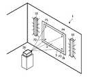
- FIG. 1shows a system 1 for controlling the lighting of a room in accordance with an image 2 projected onto a projection surface 3 s of a projection screen device 3 .
- a projection unit 20any apparatus can be used that is designed to project images onto a screen.
- the projection screen 3contains four measuring points P 1 , P 2 , P 3 , P 4 at the edges of the screen at which optical sensors measure characteristic features of the image 2 projected onto the projection screen 3 .
- the projection screen device 3 of the system 1is shown in more detail. Behind each of the four measuring points P 1 , P 2 , P 3 , P 4 a sensor 5 is mounted on a wall in the direction of projection.
- the screen of the projection screen device 3is semitransparent at the measuring points P 1 , P 2 , P 3 , P 4 , and light from the projected image 2 passes through the projection screen to the optical sensors 5 which measure characteristic features of the light passing through.
- a control unitnot shown in FIGS. 1 and 2 , generates a control signal for the room lighting which reacts accordingly.
- the room lightingcan be a pair of wall washers 10 , i.e. lighting devices 10 for evenly illuminating vertical surfaces ( FIG. 1 ). This technique will be known to a person skilled in the art and does not need to be described in more detail here.
- Each lighting deviceilluminates a zone of a “surrounding area” SA of the projection surface, e.g. of the wall behind the projection screen, on the basis of the measurement of the optical sensor 5 .
- the lighting devices 10may also be hidden behind the projection screen 3 so that they are not visible from the normal view of a user.
- the measuring of the characteristic features of the light at different measuring points P 1 , P 2 , P 3 , P 4has the advantage that different characteristic features may be acquired for different measuring areas A 1 , A 2 , A 3 , A 4 of the image 2 .
- a dominant colour of the respective measuring area A 1 , A 2 , A 3 , A 4is determined in each of the measuring areas A 1 , A 2 , A 3 , A 4 at the four edges of the image 2 .
- a dominant colour of the respective measuring area A 1 , A 2 , A 3 , A 4is determined.
- the corresponding zones Z 1 , Z 2 , Z 3 , Z 4 of the surrounding area SA at the edges of the projecting surface 3 sare illuminated with light in a similar colour.
- FIG. 3The functional components of the lighting system 1 are shown in FIG. 3 in a schematic block diagram.
- An electro-optical sensor 5is connected to an input interface 8 of a control device 9 to feed electrical signals generated by the sensor 5 , comprising or representing the characteristic features of the light received by the sensor 5 , to the control device 9 .
- This control device 9comprises a control unit 6 which analyses the electrical signal and extracts characteristic features like luminous intensity and colour, e.g. as a RGB value.
- the control unit 6generates control signals CS 1 , CS 2 , CS 3 which can for instance drive the light sources S 1 , S 2 , S 3 of a lighting device 10 connected on an outgoing interface 7 of the control device 9 such that the light emitted by the lighting device 10 matches the measured characteristic features.
- the light sources S 1 , S 2 , S 3can be three lamps, where the first lamp S 1 is equipped with a red colour filter, the second lamp S 2 with a green filter and the third lamp S 3 with a blue filter, so that different colours and colour intensities can be produced by controlling the light output of the lamps S 1 , S 2 , S 3 individually with the control signals CS 1 , CS 2 , CS 3 .
- the lighting device 10could, for instance produce a red light of high luminous intensity by only activating the lamp S 1 with the red filter but with high output power.
- a yellow lightcan be achieved by activating the lamp S 1 with the red filter and additionally activating the lamp S 2 with the green filter, since red and green light combine to give light of a yellow colour.
- High and low intensity light of a colourcan be achieved by increasing and decreasing output power of the lamps S 1 , S 2 , S 3 equally, i.e. balancing the relative intensity. For instance a bright yellow can be achieved by combining bright red and bright green light; a dark yellow light can be achieved by combining by low red and low green light. The combination of light with red, green and yellow components at certain intensities then yields a defined colour emitted by the lighting device 10 .
- the sensor 5 and the control device 9give a control system 11 according to an embodiment of the invention to control any lighting arrangement.
- Such a lighting system 10may also be completely integrated in a single stand-alone device as shown in FIG. 4 .
- a common housing 12all components shown in FIG. 3 , an optical sensor 5 , a control unit 6 and light sources S 1 , S 2 , S 3 , are integrated.
- each lamp S 1 , S 2 , S 3can be assigned to one of the colours red, green and blue and the control signals CS 1 , CS 2 , CS 3 drives the lamps S 1 , S 2 , S 3 individually to output certain intensity.
- a stand alone lighting system 10may be used behind the four edges of a projection screen similar to FIG. 2 in order to independently illuminate the zones Z 1 , Z 2 , Z 3 , Z 4 of the surrounding area SA at the different edges of the screen with a light adapted to the dominant colour of the image 2 in the corresponding measuring areas A 1 , A 2 , A 3 , A 4 .
- a “unit” or “module”can comprise a number of units or modules, unless otherwise stated.
Landscapes
- Engineering & Computer Science (AREA)
- Multimedia (AREA)
- Signal Processing (AREA)
- Automation & Control Theory (AREA)
- Business, Economics & Management (AREA)
- Life Sciences & Earth Sciences (AREA)
- Biodiversity & Conservation Biology (AREA)
- Ecology (AREA)
- Emergency Management (AREA)
- Environmental & Geological Engineering (AREA)
- Environmental Sciences (AREA)
- Remote Sensing (AREA)
- Projection Apparatus (AREA)
- Non-Portable Lighting Devices Or Systems Thereof (AREA)
- Transforming Electric Information Into Light Information (AREA)
Abstract
Description
Claims (4)
Applications Claiming Priority (4)
| Application Number | Priority Date | Filing Date | Title |
|---|---|---|---|
| EP07104045.5 | 2007-03-13 | ||
| EP07104045 | 2007-03-13 | ||
| EP07104045 | 2007-03-13 | ||
| PCT/IB2008/050855WO2008110973A1 (en) | 2007-03-13 | 2008-03-10 | Method of controlling the lighting of a room in accordance with an image projected onto a projection surface |
Publications (2)
| Publication Number | Publication Date |
|---|---|
| US20100110387A1 US20100110387A1 (en) | 2010-05-06 |
| US8690362B2true US8690362B2 (en) | 2014-04-08 |
Family
ID=39638842
Family Applications (1)
| Application Number | Title | Priority Date | Filing Date |
|---|---|---|---|
| US12/530,544Expired - Fee RelatedUS8690362B2 (en) | 2007-03-13 | 2008-03-10 | Method of controlling the lighting of a room in accordance with an image projected onto a projection surface |
Country Status (5)
| Country | Link |
|---|---|
| US (1) | US8690362B2 (en) |
| EP (1) | EP2135490B1 (en) |
| JP (1) | JP5371788B2 (en) |
| CN (1) | CN101658070A (en) |
| WO (1) | WO2008110973A1 (en) |
Cited By (14)
| Publication number | Priority date | Publication date | Assignee | Title |
|---|---|---|---|---|
| US9642219B2 (en) | 2014-06-05 | 2017-05-02 | Steelcase Inc. | Environment optimization for space based on presence and activities |
| US9852388B1 (en) | 2014-10-03 | 2017-12-26 | Steelcase, Inc. | Method and system for locating resources and communicating within an enterprise |
| US9921726B1 (en) | 2016-06-03 | 2018-03-20 | Steelcase Inc. | Smart workstation method and system |
| US9955318B1 (en) | 2014-06-05 | 2018-04-24 | Steelcase Inc. | Space guidance and management system and method |
| US10161752B1 (en) | 2014-10-03 | 2018-12-25 | Steelcase Inc. | Method and system for locating resources and communicating within an enterprise |
| US10264213B1 (en) | 2016-12-15 | 2019-04-16 | Steelcase Inc. | Content amplification system and method |
| US10353664B2 (en) | 2014-03-07 | 2019-07-16 | Steelcase Inc. | Method and system for facilitating collaboration sessions |
| US10433646B1 (en) | 2014-06-06 | 2019-10-08 | Steelcaase Inc. | Microclimate control systems and methods |
| US10733371B1 (en) | 2015-06-02 | 2020-08-04 | Steelcase Inc. | Template based content preparation system for use with a plurality of space types |
| US11321643B1 (en) | 2014-03-07 | 2022-05-03 | Steelcase Inc. | Method and system for facilitating collaboration sessions |
| US20220201822A1 (en)* | 2019-04-24 | 2022-06-23 | Panasonic Intellectual Property Management Co., Ltd. | Illumination control system |
| US11744376B2 (en) | 2014-06-06 | 2023-09-05 | Steelcase Inc. | Microclimate control systems and methods |
| US11984739B1 (en) | 2020-07-31 | 2024-05-14 | Steelcase Inc. | Remote power systems, apparatus and methods |
| US12118178B1 (en) | 2020-04-08 | 2024-10-15 | Steelcase Inc. | Wayfinding services method and apparatus |
Families Citing this family (18)
| Publication number | Priority date | Publication date | Assignee | Title |
|---|---|---|---|---|
| JP5401940B2 (en)* | 2008-11-17 | 2014-01-29 | セイコーエプソン株式会社 | Projection optical system zoom ratio measurement method, projection image correction method using the zoom ratio measurement method, and projector for executing the correction method |
| BR112012018378A2 (en) | 2010-01-27 | 2016-04-26 | Koninkl Philips Electronics Nv | Method for controlling a video lighting system, video lighting system, video system and control system |
| JP6011157B2 (en)* | 2011-09-05 | 2016-10-19 | 株式会社リコー | Projection system, projection device, sensor device, power generation control method, and power generation control program |
| CN103068095A (en)* | 2011-10-21 | 2013-04-24 | 扬升照明股份有限公司 | Lighting system and control method thereof |
| JP2014032750A (en)* | 2012-08-01 | 2014-02-20 | Seiko Epson Corp | Illumination system, illumination method, and illumination program |
| US20140104293A1 (en)* | 2012-10-17 | 2014-04-17 | Adam Li | Ambient light effect in video gaming |
| JP6688983B2 (en)* | 2015-03-12 | 2020-04-28 | パナソニックIpマネジメント株式会社 | Lighting system |
| CN105072430B (en)* | 2015-08-19 | 2017-10-03 | 海信集团有限公司 | A kind of method and apparatus for adjusting projected image |
| EP3344016A4 (en)* | 2015-08-26 | 2018-08-01 | Panasonic Intellectual Property Management Co., Ltd. | Illumination system and program |
| CN105460107A (en)* | 2015-12-21 | 2016-04-06 | 黎华裕 | Bicycle with attention device |
| CN109845408B (en)* | 2016-10-18 | 2021-11-30 | 昕诺飞控股有限公司 | Illumination control |
| WO2018219733A1 (en) | 2017-05-29 | 2018-12-06 | Philips Lighting Holding B.V. | A lighting system and a method of blending visual content with lighting |
| IT201700099120A1 (en)* | 2017-09-05 | 2019-03-05 | Salvatore Lamanna | LIGHTING SYSTEM FOR SCREEN OF ANY KIND |
| WO2019162193A1 (en)* | 2018-02-26 | 2019-08-29 | Signify Holding B.V. | Resuming a dynamic light effect in dependence on an effect type and/or user preference |
| PL3760008T3 (en)* | 2018-02-27 | 2022-01-17 | Signify Holding B.V. | Rendering a dynamic light scene based on one or more light settings |
| CN111836442B (en)* | 2019-03-29 | 2022-06-21 | 福建天泉教育科技有限公司 | Control method and system for light during projection |
| CN111836443B (en)* | 2019-03-29 | 2022-06-21 | 福建天泉教育科技有限公司 | Control method and system for light during projection |
| CN111836441B (en)* | 2019-03-29 | 2022-06-21 | 福建天泉教育科技有限公司 | Control method and system for light during projection |
Citations (10)
| Publication number | Priority date | Publication date | Assignee | Title |
|---|---|---|---|---|
| JPH05107638A (en)* | 1991-10-18 | 1993-04-30 | Fujitsu General Ltd | Projection type display device |
| US5570138A (en) | 1994-02-04 | 1996-10-29 | Baron; Hal | Combination outdoor daytime/nighttime advertising billboard |
| US6606130B1 (en) | 1999-06-30 | 2003-08-12 | Thomson Licensing S.A. | Projection video display with multiple photo sensors |
| US6611297B1 (en) | 1998-04-13 | 2003-08-26 | Matsushita Electric Industrial Co., Ltd. | Illumination control method and illumination device |
| US20030214640A1 (en)* | 2001-05-16 | 2003-11-20 | Sony Corporation | Imaging prevention method and system |
| WO2004112386A1 (en) | 2003-06-12 | 2004-12-23 | Koninklijke Philips Electronics N.V. | Device for simultaneously projecting images and illuminating the ambient |
| US20050041164A1 (en) | 2003-08-01 | 2005-02-24 | Takeshi Sato | Video output device and method |
| EP1551178A1 (en) | 2003-12-18 | 2005-07-06 | Koninklijke Philips Electronics N.V. | Supplementary visual display system |
| WO2006003604A1 (en) | 2004-06-30 | 2006-01-12 | Koninklijke Philips Electronics, N.V. | Active frame system for ambient lighting using a video display as a signal s0urce |
| US8130184B2 (en)* | 2005-10-21 | 2012-03-06 | Hewlett-Packard Development Company L. P. | Image pixel transformation |
Family Cites Families (9)
| Publication number | Priority date | Publication date | Assignee | Title |
|---|---|---|---|---|
| ES534455A0 (en) | 1983-07-20 | 1985-09-01 | Graphics Inc | A METHOD FOR PRODUCING PERMANENT COLORED IMAGES IN AN ARTICLE |
| DE3913634C2 (en)* | 1989-04-26 | 1997-07-03 | Sel Alcatel Ag | Method and device for setting convergence for projection devices |
| JP3409899B2 (en)* | 1993-12-13 | 2003-05-26 | 三菱電機株式会社 | Projection display device and projection image improvement method |
| JP4399087B2 (en)* | 2000-05-31 | 2010-01-13 | パナソニック株式会社 | LIGHTING SYSTEM, VIDEO DISPLAY DEVICE, AND LIGHTING CONTROL METHOD |
| JP2002214700A (en)* | 2001-01-17 | 2002-07-31 | Hitachi Ltd | Rear projector |
| JP2005031572A (en)* | 2003-07-11 | 2005-02-03 | Sharp Corp | Projector image quality correction system |
| US7645942B2 (en)* | 2005-12-09 | 2010-01-12 | Xerox Corporation | Electrical interconnect with maximized electrical contact |
| US20090165296A1 (en)* | 2006-04-04 | 2009-07-02 | Yoash Carmi | Patterns of conductive objects on a substrate and method of producing thereof |
| US8059049B2 (en)* | 2006-10-11 | 2011-11-15 | Raytheon Company | Dual band active array antenna |
- 2008
- 2008-03-10EPEP08719616.8Apatent/EP2135490B1/ennot_activeNot-in-force
- 2008-03-10USUS12/530,544patent/US8690362B2/ennot_activeExpired - Fee Related
- 2008-03-10WOPCT/IB2008/050855patent/WO2008110973A1/enactiveApplication Filing
- 2008-03-10CNCN200880008167Apatent/CN101658070A/enactivePending
- 2008-03-10JPJP2009553250Apatent/JP5371788B2/ennot_activeExpired - Fee Related
Patent Citations (11)
| Publication number | Priority date | Publication date | Assignee | Title |
|---|---|---|---|---|
| JPH05107638A (en)* | 1991-10-18 | 1993-04-30 | Fujitsu General Ltd | Projection type display device |
| US5570138A (en) | 1994-02-04 | 1996-10-29 | Baron; Hal | Combination outdoor daytime/nighttime advertising billboard |
| US6611297B1 (en) | 1998-04-13 | 2003-08-26 | Matsushita Electric Industrial Co., Ltd. | Illumination control method and illumination device |
| US6606130B1 (en) | 1999-06-30 | 2003-08-12 | Thomson Licensing S.A. | Projection video display with multiple photo sensors |
| US20030214640A1 (en)* | 2001-05-16 | 2003-11-20 | Sony Corporation | Imaging prevention method and system |
| WO2004112386A1 (en) | 2003-06-12 | 2004-12-23 | Koninklijke Philips Electronics N.V. | Device for simultaneously projecting images and illuminating the ambient |
| US20050041164A1 (en) | 2003-08-01 | 2005-02-24 | Takeshi Sato | Video output device and method |
| EP1551178A1 (en) | 2003-12-18 | 2005-07-06 | Koninklijke Philips Electronics N.V. | Supplementary visual display system |
| US8233033B2 (en)* | 2003-12-18 | 2012-07-31 | Tp Vision Holding B.V. | Supplementary visual display system |
| WO2006003604A1 (en) | 2004-06-30 | 2006-01-12 | Koninklijke Philips Electronics, N.V. | Active frame system for ambient lighting using a video display as a signal s0urce |
| US8130184B2 (en)* | 2005-10-21 | 2012-03-06 | Hewlett-Packard Development Company L. P. | Image pixel transformation |
Cited By (47)
| Publication number | Priority date | Publication date | Assignee | Title |
|---|---|---|---|---|
| US11321643B1 (en) | 2014-03-07 | 2022-05-03 | Steelcase Inc. | Method and system for facilitating collaboration sessions |
| US11150859B2 (en) | 2014-03-07 | 2021-10-19 | Steelcase Inc. | Method and system for facilitating collaboration sessions |
| US12001976B1 (en) | 2014-03-07 | 2024-06-04 | Steelcase Inc. | Method and system for facilitating collaboration sessions |
| US10353664B2 (en) | 2014-03-07 | 2019-07-16 | Steelcase Inc. | Method and system for facilitating collaboration sessions |
| US11979959B1 (en) | 2014-06-05 | 2024-05-07 | Steelcase Inc. | Environment optimization for space based on presence and activities |
| US9642219B2 (en) | 2014-06-05 | 2017-05-02 | Steelcase Inc. | Environment optimization for space based on presence and activities |
| US11307037B1 (en) | 2014-06-05 | 2022-04-19 | Steelcase Inc. | Space guidance and management system and method |
| US10225707B1 (en) | 2014-06-05 | 2019-03-05 | Steelcase Inc. | Space guidance and management system and method |
| US12324072B2 (en) | 2014-06-05 | 2025-06-03 | Steelcase Inc. | Environment optimization for space based on presence and activities |
| US9955318B1 (en) | 2014-06-05 | 2018-04-24 | Steelcase Inc. | Space guidance and management system and method |
| US11402217B1 (en) | 2014-06-05 | 2022-08-02 | Steelcase Inc. | Space guidance and management system and method |
| US10057963B2 (en) | 2014-06-05 | 2018-08-21 | Steelcase Inc. | Environment optimization for space based on presence and activities |
| US10561006B2 (en) | 2014-06-05 | 2020-02-11 | Steelcase Inc. | Environment optimization for space based on presence and activities |
| US12375874B1 (en) | 2014-06-05 | 2025-07-29 | Steelcase Inc. | Space guidance and management system and method |
| US11280619B1 (en) | 2014-06-05 | 2022-03-22 | Steelcase Inc. | Space guidance and management system and method |
| US11402216B1 (en) | 2014-06-05 | 2022-08-02 | Steelcase Inc. | Space guidance and management system and method |
| US11212898B2 (en) | 2014-06-05 | 2021-12-28 | Steelcase Inc. | Environment optimization for space based on presence and activities |
| US11085771B1 (en) | 2014-06-05 | 2021-08-10 | Steelcase Inc. | Space guidance and management system and method |
| US11744376B2 (en) | 2014-06-06 | 2023-09-05 | Steelcase Inc. | Microclimate control systems and methods |
| US10433646B1 (en) | 2014-06-06 | 2019-10-08 | Steelcaase Inc. | Microclimate control systems and methods |
| US11168987B2 (en) | 2014-10-03 | 2021-11-09 | Steelcase Inc. | Method and system for locating resources and communicating within an enterprise |
| US11143510B1 (en) | 2014-10-03 | 2021-10-12 | Steelcase Inc. | Method and system for locating resources and communicating within an enterprise |
| US10970662B2 (en) | 2014-10-03 | 2021-04-06 | Steelcase Inc. | Method and system for locating resources and communicating within an enterprise |
| US10161752B1 (en) | 2014-10-03 | 2018-12-25 | Steelcase Inc. | Method and system for locating resources and communicating within an enterprise |
| US10121113B1 (en) | 2014-10-03 | 2018-11-06 | Steelcase Inc. | Method and system for locating resources and communicating within an enterprise |
| US11713969B1 (en) | 2014-10-03 | 2023-08-01 | Steelcase Inc. | Method and system for locating resources and communicating within an enterprise |
| US11687854B1 (en) | 2014-10-03 | 2023-06-27 | Steelcase Inc. | Method and system for locating resources and communicating within an enterprise |
| US9852388B1 (en) | 2014-10-03 | 2017-12-26 | Steelcase, Inc. | Method and system for locating resources and communicating within an enterprise |
| US11100282B1 (en) | 2015-06-02 | 2021-08-24 | Steelcase Inc. | Template based content preparation system for use with a plurality of space types |
| US10733371B1 (en) | 2015-06-02 | 2020-08-04 | Steelcase Inc. | Template based content preparation system for use with a plurality of space types |
| US10459611B1 (en) | 2016-06-03 | 2019-10-29 | Steelcase Inc. | Smart workstation method and system |
| US11956838B1 (en) | 2016-06-03 | 2024-04-09 | Steelcase Inc. | Smart workstation method and system |
| US11690111B1 (en) | 2016-06-03 | 2023-06-27 | Steelcase Inc. | Smart workstation method and system |
| US9921726B1 (en) | 2016-06-03 | 2018-03-20 | Steelcase Inc. | Smart workstation method and system |
| US11330647B2 (en) | 2016-06-03 | 2022-05-10 | Steelcase Inc. | Smart workstation method and system |
| US12213191B1 (en) | 2016-06-03 | 2025-01-28 | Steelcase Inc. | Smart workstation method and system |
| US12231810B1 (en) | 2016-12-15 | 2025-02-18 | Steelcase Inc. | Content amplification system and method |
| US10897598B1 (en) | 2016-12-15 | 2021-01-19 | Steelcase Inc. | Content amplification system and method |
| US10638090B1 (en) | 2016-12-15 | 2020-04-28 | Steelcase Inc. | Content amplification system and method |
| US11190731B1 (en) | 2016-12-15 | 2021-11-30 | Steelcase Inc. | Content amplification system and method |
| US11652957B1 (en) | 2016-12-15 | 2023-05-16 | Steelcase Inc. | Content amplification system and method |
| US10264213B1 (en) | 2016-12-15 | 2019-04-16 | Steelcase Inc. | Content amplification system and method |
| US11882639B2 (en)* | 2019-04-24 | 2024-01-23 | Panasonic Intellectual Property Management Co., Ltd. | Illumination control system |
| US20220201822A1 (en)* | 2019-04-24 | 2022-06-23 | Panasonic Intellectual Property Management Co., Ltd. | Illumination control system |
| US12118178B1 (en) | 2020-04-08 | 2024-10-15 | Steelcase Inc. | Wayfinding services method and apparatus |
| US11984739B1 (en) | 2020-07-31 | 2024-05-14 | Steelcase Inc. | Remote power systems, apparatus and methods |
| US12341360B1 (en) | 2020-07-31 | 2025-06-24 | Steelcase Inc. | Remote power systems, apparatus and methods |
Also Published As
| Publication number | Publication date |
|---|---|
| WO2008110973A1 (en) | 2008-09-18 |
| CN101658070A (en) | 2010-02-24 |
| EP2135490A1 (en) | 2009-12-23 |
| JP2010521773A (en) | 2010-06-24 |
| JP5371788B2 (en) | 2013-12-18 |
| EP2135490B1 (en) | 2013-08-28 |
| US20100110387A1 (en) | 2010-05-06 |
Similar Documents
| Publication | Publication Date | Title |
|---|---|---|
| US8690362B2 (en) | Method of controlling the lighting of a room in accordance with an image projected onto a projection surface | |
| US9247611B2 (en) | Light source with light sensor | |
| KR101594135B1 (en) | Method and system for filming | |
| EP2739903B1 (en) | Multimode color tunable light source | |
| JP2008522210A (en) | Display system | |
| EP2430885A1 (en) | Lighting arrangement | |
| KR20100067638A (en) | Setting an rgb luminous module | |
| JP2008505350A (en) | An active frame system for ambient light using a video display as a signal source. | |
| CN106102248B (en) | A kind of illumination control method, lighting device and terminal | |
| JP2008277092A (en) | Lighting device | |
| US10667343B2 (en) | Modular solid state lighting apparatus platform with local and remote microprocessor control | |
| CN113669683A (en) | Arrangements for producing different spectra and similar colours | |
| CN104955208A (en) | Lighting system, lighting control system, and lighting system unit | |
| CN101802688A (en) | Illumination unit and method for driving the illumination unit | |
| Lin et al. | The study of a novel control method of the mood lighting emulator | |
| JP2008204855A (en) | Variable color vertical type illuminating apparatus and variable color vertical type illumination system | |
| CN109068434A (en) | A kind of displaying device adjusting colour temperature and brightness | |
| CN205247027U (en) | Light generator, image equipment and image system | |
| US20100245673A1 (en) | Illumination device | |
| CN208158940U (en) | A kind of displaying device adjusting colour temperature and brightness | |
| TW201227686A (en) | Liquid crystal display and driving method therefor | |
| KR101819611B1 (en) | Method and system for filming | |
| US12315467B2 (en) | Systems and methods for creating illusions of skylights and windows | |
| JP2004125586A (en) | Color matching system and method |
Legal Events
| Date | Code | Title | Description |
|---|---|---|---|
| AS | Assignment | Owner name:KONINKLIJKE PHILIPS ELECTRONICS N V,NETHERLANDS Free format text:ASSIGNMENT OF ASSIGNORS INTEREST;ASSIGNOR:WENDT, MATTHIAS;REEL/FRAME:023211/0109 Effective date:20080924 Owner name:KONINKLIJKE PHILIPS ELECTRONICS N V, NETHERLANDS Free format text:ASSIGNMENT OF ASSIGNORS INTEREST;ASSIGNOR:WENDT, MATTHIAS;REEL/FRAME:023211/0109 Effective date:20080924 | |
| AS | Assignment | Owner name:PHILIPS LIGHTING HOLDING B.V., NETHERLANDS Free format text:ASSIGNMENT OF ASSIGNORS INTEREST;ASSIGNOR:KONINKLIJKE PHILIPS N.V.;REEL/FRAME:040060/0009 Effective date:20160607 | |
| FEPP | Fee payment procedure | Free format text:MAINTENANCE FEE REMINDER MAILED (ORIGINAL EVENT CODE: REM.) | |
| LAPS | Lapse for failure to pay maintenance fees | Free format text:PATENT EXPIRED FOR FAILURE TO PAY MAINTENANCE FEES (ORIGINAL EVENT CODE: EXP.) | |
| STCH | Information on status: patent discontinuation | Free format text:PATENT EXPIRED DUE TO NONPAYMENT OF MAINTENANCE FEES UNDER 37 CFR 1.362 | |
| FP | Lapsed due to failure to pay maintenance fee | Effective date:20180408 |