US8689864B2 - Activation device - Google Patents
Activation deviceDownload PDFInfo
- Publication number
- US8689864B2 US8689864B2US12/665,641US66564108AUS8689864B2US 8689864 B2US8689864 B2US 8689864B2US 66564108 AUS66564108 AUS 66564108AUS 8689864 B2US8689864 B2US 8689864B2
- Authority
- US
- United States
- Prior art keywords
- pinion
- elongate member
- toothed surface
- tooth
- surface portion
- Prior art date
- Legal status (The legal status is an assumption and is not a legal conclusion. Google has not performed a legal analysis and makes no representation as to the accuracy of the status listed.)
- Active, expires
Links
Images


Classifications
- E—FIXED CONSTRUCTIONS
- E21—EARTH OR ROCK DRILLING; MINING
- E21B—EARTH OR ROCK DRILLING; OBTAINING OIL, GAS, WATER, SOLUBLE OR MELTABLE MATERIALS OR A SLURRY OF MINERALS FROM WELLS
- E21B34/00—Valve arrangements for boreholes or wells
- E21B34/06—Valve arrangements for boreholes or wells in wells
- E21B34/12—Valve arrangements for boreholes or wells in wells operated by movement of casings or tubings
- E—FIXED CONSTRUCTIONS
- E21—EARTH OR ROCK DRILLING; MINING
- E21B—EARTH OR ROCK DRILLING; OBTAINING OIL, GAS, WATER, SOLUBLE OR MELTABLE MATERIALS OR A SLURRY OF MINERALS FROM WELLS
- E21B23/00—Apparatus for displacing, setting, locking, releasing or removing tools, packers or the like in boreholes or wells
- E21B23/06—Apparatus for displacing, setting, locking, releasing or removing tools, packers or the like in boreholes or wells for setting packers
Definitions
- the present inventionrelates a device for activating a downhole tool, particularly, but not exclusively for activating a packer.
- Each cup sealis initially moved into engagement with the conduit wall by applying a force to the internal surface of the cup. This is generally achieved by moving a ramp into the cup. The ramp is moved by the application of a force from surface. As the cup seals face in opposite directions, the force must be applied in opposite directions to each seal.
- An object of at least one embodiment of the present inventionis to obviate or mitigate at least one of the aforementioned problems.
- a device for activating a downhole toolcomprising:
- a first elongate memberdefining a toothed surface portion
- At least one pinion arrangementengaging the toothed surface portions of the first and second members such that movement of one member in a first direction results in movement of the other member in a second direction, opposite the first direction.
- Such an arrangementpermits, in one embodiment, a pull force applied from the surface of an oil well to be converted to a push force at a location downhole.
- the at least one of the first and second membersare tubular.
- both of the first and second membersare tubular.
- the first member external diameteris less than the second member internal diameter.
- the first tubular member toothed surface portionis defined by an external surface.
- the second tubular member toothed surface portionis defined by an internal surface.
- the teeth on each toothed surface portionare arranged transverse to the direction of movement of the toothed surface.
- the toothed surface portionsare opposed.
- the/each pinion arrangementis positioned between the first and second members.
- the/each pinion arrangementcomprises a single pinion. Such a construction will result in equal movement of the first and second members.
- the/each pinion arrangementcomprises multiple pinions.
- Such a constructionpermits unequal movement of the first and second members. In some cases, for example, it may be desirable to have a large input movement in the first direction resulting in a smaller movement in the second direction to provide for fine adjustment.
- the/each pinion arrangementcomprises a single pinion
- the/each pinioncomprises an at least one first pinion region and an at least one second pinion region.
- the number of teeth on the/each first pinion regionis different to the number of teeth on the/each second pinion region. This arrangement also permits unequal movement of the first and second members.
- the/each pinion toothdefines a profile comprising a plurality of portions.
- each pinion tooth or pinion tooth portionis linear.
- At least one of said linear profile portionsis adapted to mesh with the first tubular member toothed surface.
- At least one other of said linear profile portionsis adapted to mesh with the second tubular member toothed surface.
- adjacent linear profile portionsare angled with respect to each other.
- each pinion toothdefines a profile comprising a plurality of linear portions, adjacent linear portions being angled with respect to one another.
- the/each piniondefines a profile comprising at least one convex portion and at least one concave portion.
- the/each concave portionis adapted to mesh with the first tubular member toothed surface.
- the/each convex portionis adapted to mesh with the second tubular member toothed surface.
- each pinion toothdefines a profile comprising at least one convex portion and at least one concave portion.
- the teeth of the at least one first pinion regiondefine a convex profile and the teeth of the at least one second pinion region define a concave profile.
- the/each pinionis adapted to rotate around a journal.
- the/each pinion arrangementcomprises a plurality of pinions
- at least some of the pinionsrotate around the same journal.
- the/each journalis fixed with respect to the first and second members.
- movement of one memberequates to an equal movement of the other member.
- the devicefurther comprises a pinion support adapted support the/each pinion arrangement.
- the pinion supportdefines at least one aperture, the/each, aperture adapted to receive a pinion arrangement.
- the pinion supportis a tubular.
- the first member, the pinion support and the second memberare arranged concentrically.
- the pinion supporthas an internal diameter greater than the external diameter of the first member.
- the pinion supporthas an external diameter less than the internal diameter of the second member.
- one of the first or second membersis adapted to be engaged by a setting tool.
- the first memberis adapted to be engaged by the setting tool.
- one of the first or second membersis adapted to engage a packer.
- An embodiment of the present inventionis adapted to engage a packer as described in the Applicant's co-pending application number PCT/GB2007/001040.
- the first and second membersare adapted to move axially with respect to the pinion support.
- a method of setting a pair of opposed seals in a wellborecomprising the steps of:
- the first seal activation meansutilising the force to apply a force in the first direction to a first seal to set the first seal;
- the second seal activation meansutilising the force to apply a force in a second direction, opposite the first direction, to a second seal to set the second seal.
- the second seal activation apparatuscomprises:
- a first elongate memberdefining a toothed surface portion
- At least one pinion arrangementengaging the toothed surfaces of the first and second members such that movement of one member in a first direction results in movement of the other member in a second direction, opposite the first direction.
- FIG. 1is a section view of a device for activating a downhole tool, shown connected to a sealing tool, according to a first embodiment of the present invention
- FIG. 2is a close up section view of the device of FIG. 1 ;
- FIG. 3is a perspective view of one of the pinions of the device of FIG. 1 ;
- FIG. 4is a side view of the pinion of FIG. 3 ;
- FIG. 5is a section view through section B-B referenced on FIG. 2 ;
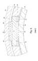
- FIG. 6is a close up view of detail C referenced on FIG. 5 ;
- FIG. 7is a side view of an alternative pinion, according to a second embodiment of the present invention.
- FIG. 1there is a shown a section view of a device, generally indicated by reference numeral 10 , for activating a downhole tool 12 , in this case a packer, according to a first embodiment of the present invention.
- the device 10 and packer 12are part of a tool string 14 which extends from a well head (not shown) through a well bore 16 .
- the well bore 16is an open hole having a surface 18 .
- the packer 12comprises a cup seal 22 , which is adapted to be expanded from the position shown in solid outline to the position shown in broken outline on FIG. 1 .
- a ramp apparatus 20is provided to expand the cup seal 22 .
- the ramp apparatus 20is adapted to move down the tool string 14 in the direction of arrow A, behind the cup seal 22 , expanding the seal element 22 .
- the ramp apparatus 20is moved in the direction of arrow A by the activation device 10 which will now be described with reference to FIG. 2 , a close up section view of the device 10 of FIG. 1 .
- the device 10comprises a first elongate tubular member 30 and a second elongate tubular member 32 .
- a portion of the external surface 34 of the first elongate member 30defines a toothed surface 36 .
- a portion of the internal surface 38 of the second elongate tubular memberalso defines a toothed surface 40 .
- the device 10also comprises six pinions 42 (of which two are visible) located in apertures 44 defined by a tubular pinion support mandrel 46 . Therefore, as can be seen from FIG. 1 , starting from the inside, the first member 30 , the pinion support mandrel 46 and the second tubular member 32 are arranged concentrically.
- Each pinion 42engages both toothed surfaces 36 , 40 at the same time, such that movement of the first elongate tubular member 30 in the direction of arrow B results in the movement of the second elongate tubular member 32 in the direction of arrow C, opposite to the direction of arrow B.
- the second elongate tubular member 32is connected to the upper end 48 of the ramp apparatus 20 by means of a threaded connection 50 . Therefore, movement of the second elongate tubular member 32 results in equal movement of the ramp apparatus 20 .
- the internal surface 52 of the first elongate tubular member 30defines a profiled portion 54 adapted to be engaged by a setting tool (not shown). Once engaged an upward pulling force can be applied to the first elongate tubular member, in the direction of arrow B, resulting in movement of the second tubular member 32 and the ramp apparatus 20 in the opposite direction, thereby setting the packer 12 .
- the second tubular member 32is pinned to the pinion support mandrel 46 by six shear pins 56 .
- the force applied by the setting tool (not shown) to the first tubular member 30must be sufficient to overcome the shear pins 56 before the tubular members 30 , 32 will move to set the cup seal 22 .
- the setting toolcan be utilised to first set the lower seal element by applying a simple pull force to the ramp apparatus associated with that seal element.
- the lower ramp apparatuswill move up the tool to set a lower cup seal.
- the setting toolcan pass up the tool until engagement with the first tubular member profile portion 54 to set the upper sealing element 22 .
- the pinions 42will now be described in more detail, firstly with reference to FIGS. 3 and 4 perspective and side views of a pinion 42 of the device 10 of FIG. 1 .
- Each pinion 42comprises a plurality of teeth 60 arranged axially down the length of the pinion body 62 .
- Each tooth 60comprises a central portion 64 and first and second end portions 66 , 68 .
- the first and second end portions 66 , 68are convex whereas the central portion 64 is concave. This arrangement is adopted to facilitate the meshing of the pinion teeth 60 with the curved tooth surfaces 36 , 40 of the tubular members 30 , 32 .
- FIG. 5being a section view through section B-B referenced on FIG. 2 and section 6 being a close-up of detail C referenced on FIG. 5 .
- the concave central portion 64 of the pinions 42engage the convex toothed surface 36 of the first elongate tubular member 30 .
- the convex end portions 66engage with the concaved internal toothed surface 40 of the second elongate member 32 .
- each pinion 42is mounted to a journal 70 , each journal 70 being axially fixed with respect to the pinion support mandrel 46 by journal bearings 72 .
- FIG. 7a side view of an alternative pinion 142 , according to a second embodiment of the present invention.
- the pinion 142is largely the same as the pinion 42 of the first embodiment with the exception that the central portion 164 and the first and second end portions 166 , 168 define linear profiles. As shown in FIG. 6 , the profiles are angled to each other but this is not necessarily the case.
- the pinion 142operates with the other components of the activation device in the same way as the pinion 42 .
- each pinioncould be replaced by two meshing gears such that the input movement applied to the first tubular member could result in a greater or lesser output movement of the second tubular member.
- each pinioncould comprises two regions, one for meshing with the first tubular and one for meshing with the second tubular, each region having a different number of teeth, which would also result in a greater or lesser output movement of the second tubular member for a given input movement of the first tubular.
- the activation deviceis suitable for activating other tools which require a downhole force to be applied for activation.
Landscapes
- Life Sciences & Earth Sciences (AREA)
- Engineering & Computer Science (AREA)
- Geology (AREA)
- Mining & Mineral Resources (AREA)
- Physics & Mathematics (AREA)
- Environmental & Geological Engineering (AREA)
- Fluid Mechanics (AREA)
- General Life Sciences & Earth Sciences (AREA)
- Geochemistry & Mineralogy (AREA)
- Earth Drilling (AREA)
- Finish Polishing, Edge Sharpening, And Grinding By Specific Grinding Devices (AREA)
Abstract
Description
Claims (47)
Applications Claiming Priority (3)
| Application Number | Priority Date | Filing Date | Title |
|---|---|---|---|
| GB0711871.4 | 2007-06-20 | ||
| GBGB0711871.4AGB0711871D0 (en) | 2007-06-20 | 2007-06-20 | Improved activation device |
| PCT/GB2008/002042WO2008155526A2 (en) | 2007-06-20 | 2008-06-17 | Improved activation device |
Publications (2)
| Publication Number | Publication Date |
|---|---|
| US20110100648A1 US20110100648A1 (en) | 2011-05-05 |
| US8689864B2true US8689864B2 (en) | 2014-04-08 |
Family
ID=38332392
Family Applications (1)
| Application Number | Title | Priority Date | Filing Date |
|---|---|---|---|
| US12/665,641Active2030-06-06US8689864B2 (en) | 2007-06-20 | 2008-06-17 | Activation device |
Country Status (6)
| Country | Link |
|---|---|
| US (1) | US8689864B2 (en) |
| EP (1) | EP2156009B1 (en) |
| CA (1) | CA2692230C (en) |
| DK (1) | DK2156009T3 (en) |
| GB (1) | GB0711871D0 (en) |
| WO (1) | WO2008155526A2 (en) |
Cited By (1)
| Publication number | Priority date | Publication date | Assignee | Title |
|---|---|---|---|---|
| US20130319686A1 (en)* | 2012-05-31 | 2013-12-05 | Tesco Corporation | Centralizer connector |
Families Citing this family (1)
| Publication number | Priority date | Publication date | Assignee | Title |
|---|---|---|---|---|
| US10094189B2 (en) | 2014-06-10 | 2018-10-09 | Halliburton Energy Services, Inc. | Constant force downhole anchor tool |
Citations (61)
| Publication number | Priority date | Publication date | Assignee | Title |
|---|---|---|---|---|
| US643358A (en) | 1899-06-09 | 1900-02-13 | Matthew J Konold | Hose-coupling. |
| US1896107A (en)* | 1929-10-23 | 1933-02-07 | Richard P Simmons | Underreamer well drilling apparatus |
| US2009322A (en) | 1934-10-29 | 1935-07-23 | I C Carter | Feather-type valved well packer |
| US2181748A (en) | 1936-05-04 | 1939-11-28 | Guiberson Corp | Plunger |
| US2230447A (en) | 1939-08-26 | 1941-02-04 | Bassinger Ross | Well plug |
| US2498791A (en) | 1946-06-22 | 1950-02-28 | James M Clark | Well device |
| US2546377A (en) | 1942-01-20 | 1951-03-27 | Lane Wells Co | Bridging plug |
| US2738018A (en) | 1953-03-12 | 1956-03-13 | Oil Recovery Corp | Oil well treating and production tool |
| GB755082A (en) | 1953-10-12 | 1956-08-15 | Baker Oil Tools Inc | Subsurface well tools |
| US2832418A (en) | 1955-08-16 | 1958-04-29 | Baker Oil Tools Inc | Well packer |
| US3066738A (en) | 1958-09-08 | 1962-12-04 | Baker Oil Tools Inc | Well packer and setting device therefor |
| US3087552A (en) | 1961-10-02 | 1963-04-30 | Jersey Prod Res Co | Apparatus for centering well tools in a well bore |
| US3167127A (en) | 1961-04-04 | 1965-01-26 | Otis Eng Co | Dual well packer |
| US3167128A (en) | 1962-04-24 | 1965-01-26 | Wayne N Sutliff | Selective formation zone anchor |
| US3283821A (en) | 1963-12-05 | 1966-11-08 | Cicero C Brown | Screw-set packer |
| US3342268A (en) | 1965-09-07 | 1967-09-19 | Joe R Brown | Well packer for use with high temperature fluids |
| US3371716A (en) | 1965-10-23 | 1968-03-05 | Schlumberger Technology Corp | Bridge plug |
| US3482889A (en) | 1967-09-18 | 1969-12-09 | Driltrol | Stabilizers for drilling strings |
| US3623551A (en) | 1970-01-02 | 1971-11-30 | Schlumberger Technology Corp | Anchoring apparatus for a well packer |
| GB1257790A (en) | 1967-12-20 | 1971-12-22 | ||
| US3722588A (en) | 1971-10-18 | 1973-03-27 | J Tamplen | Seal assembly |
| US3729170A (en) | 1969-02-20 | 1973-04-24 | Hydril Co | Rotary plug valve assembly |
| GB1364054A (en) | 1972-05-11 | 1974-08-21 | Rees Ltd William F | Centring devices for locating instruments axially within tubular enclosures |
| US3889750A (en) | 1974-07-17 | 1975-06-17 | Schlumberger Technology Corp | Setting and releasing apparatus for sidewall anchor |
| US4046405A (en) | 1972-05-15 | 1977-09-06 | Mcevoy Oilfield Equipment Co. | Run-in and tie back apparatus |
| US4127168A (en) | 1977-03-11 | 1978-11-28 | Exxon Production Research Company | Well packers using metal to metal seals |
| US4317485A (en) | 1980-05-23 | 1982-03-02 | Baker International Corporation | Pump catcher apparatus |
| US4331315A (en) | 1978-11-24 | 1982-05-25 | Daniel Industries, Inc. | Actuatable safety valve for wells and flowlines |
| US4346919A (en) | 1977-09-15 | 1982-08-31 | Smith International, Inc. | Remote automatic make-up stab-in sealing system |
| US4375240A (en) | 1980-12-08 | 1983-03-01 | Hughes Tool Company | Well packer |
| GB2118659A (en) | 1982-04-19 | 1983-11-02 | Alsthom Atlantique | Anti-unscrewing device |
| US4588030A (en) | 1984-09-27 | 1986-05-13 | Camco, Incorporated | Well tool having a metal seal and bi-directional lock |
| DE3812211A1 (en) | 1988-04-13 | 1989-11-02 | Preussag Ag Bauwesen | Screw-connections for riser pipes for pumps in wells |
| US4917187A (en) | 1989-01-23 | 1990-04-17 | Baker Hughes Incorporated | Method and apparatus for hydraulically firing a perforating gun below a set packer |
| GB2224526A (en) | 1988-09-19 | 1990-05-09 | Cooper Ind Inc | Mounting of annular members having energisable sealing assemblies |
| US5058684A (en) | 1990-06-04 | 1991-10-22 | Halliburton Company | Drill pipe bridge plug |
| GB2245624A (en) | 1990-06-29 | 1992-01-08 | Baker Hughes Inc | Liner hanger assembly |
| EP0468668A2 (en) | 1990-07-25 | 1992-01-29 | Halliburton Company | Rotary locking system with metal seals |
| US5095978A (en) | 1989-08-21 | 1992-03-17 | Ava International | Hydraulically operated permanent type well packer assembly |
| EP0485080A1 (en) | 1990-10-16 | 1992-05-13 | The Red Baron (Oil Tools Rental) Limited | Locking tube connection |
| US5261488A (en) | 1990-01-17 | 1993-11-16 | Weatherford U.K. Limited | Centralizers for oil well casings |
| US5542473A (en) | 1995-06-01 | 1996-08-06 | Pringle; Ronald E. | Simplified sealing and anchoring device for a well tool |
| DE19827708A1 (en) | 1997-07-07 | 1999-01-14 | Ford Motor Co | Liquid line connection device |
| GB2328230A (en) | 1997-08-07 | 1999-02-17 | Computalog Limited | Centralizers for a downhole tool |
| US5873411A (en)* | 1997-04-07 | 1999-02-23 | Prentiss; John Gilbert | Double acting reciprocating piston pump |
| US6062309A (en) | 1997-07-11 | 2000-05-16 | Variperm Limited | Torque roller anchor |
| US6315041B1 (en) | 1999-04-15 | 2001-11-13 | Stephen L. Carlisle | Multi-zone isolation tool and method of stimulating and testing a subterranean well |
| US6345669B1 (en)* | 1997-11-07 | 2002-02-12 | Omega Completion Technology Limited | Reciprocating running tool |
| WO2002042672A2 (en) | 2000-11-22 | 2002-05-30 | Wellstream Inc. | End fitting for high pressure hoses and method of mounting |
| US20030000607A1 (en) | 2001-06-27 | 2003-01-02 | Winapex, Ltd | Centering device |
| US20040055757A1 (en) | 2002-09-24 | 2004-03-25 | Baker Hughes Incorporated | Locking apparatus with packoff capability |
| EP1408195A1 (en) | 2002-10-09 | 2004-04-14 | Weatherford/Lamb, Inc. | High expansion packer |
| WO2005026494A1 (en) | 2003-09-18 | 2005-03-24 | National Oilwell Norway As | Locking device for built pipe connections |
| US20050199389A1 (en)* | 2004-03-12 | 2005-09-15 | Dallas L. M. | Wellhead and control stack pressure test plug tool |
| US20050224227A1 (en) | 2004-04-07 | 2005-10-13 | Craig Hendrie | Self-contained centralizer system |
| WO2005121498A1 (en) | 2004-06-11 | 2005-12-22 | Petrowell Limited | Sealing system |
| WO2006046075A2 (en) | 2004-10-29 | 2006-05-04 | Petrowell Limited | Improved plug |
| GB2428708A (en) | 2005-07-30 | 2007-02-07 | Schlumberger Holdings | Wellbore tubing hanger allowing completion equipment to be rotationally oriented |
| WO2007109878A1 (en) | 2006-03-24 | 2007-10-04 | Wenzel Kenneth H | Apparatus for keeping a down hole drilling tool vertically aligned |
| US20090308592A1 (en) | 2006-03-23 | 2009-12-17 | Lee Mercer | Packer |
| US7690424B2 (en) | 2005-03-04 | 2010-04-06 | Petrowell Limited | Well bore anchors |
Family Cites Families (2)
| Publication number | Priority date | Publication date | Assignee | Title |
|---|---|---|---|---|
| US3009322A (en)* | 1959-06-30 | 1961-11-21 | Mercier Jean | Hydraulic actuator |
| US6062307A (en)* | 1997-10-24 | 2000-05-16 | Halliburton Energy Services, Inc. | Screen assemblies and methods of securing screens |
- 2007
- 2007-06-20GBGBGB0711871.4Apatent/GB0711871D0/ennot_activeCeased
- 2008
- 2008-06-17DKDK08775753.0Tpatent/DK2156009T3/enactive
- 2008-06-17WOPCT/GB2008/002042patent/WO2008155526A2/enactiveApplication Filing
- 2008-06-17CACA2692230Apatent/CA2692230C/enactiveActive
- 2008-06-17USUS12/665,641patent/US8689864B2/enactiveActive
- 2008-06-17EPEP08775753Apatent/EP2156009B1/enactiveActive
Patent Citations (62)
| Publication number | Priority date | Publication date | Assignee | Title |
|---|---|---|---|---|
| US643358A (en) | 1899-06-09 | 1900-02-13 | Matthew J Konold | Hose-coupling. |
| US1896107A (en)* | 1929-10-23 | 1933-02-07 | Richard P Simmons | Underreamer well drilling apparatus |
| US2009322A (en) | 1934-10-29 | 1935-07-23 | I C Carter | Feather-type valved well packer |
| US2181748A (en) | 1936-05-04 | 1939-11-28 | Guiberson Corp | Plunger |
| US2230447A (en) | 1939-08-26 | 1941-02-04 | Bassinger Ross | Well plug |
| US2546377A (en) | 1942-01-20 | 1951-03-27 | Lane Wells Co | Bridging plug |
| US2498791A (en) | 1946-06-22 | 1950-02-28 | James M Clark | Well device |
| US2738018A (en) | 1953-03-12 | 1956-03-13 | Oil Recovery Corp | Oil well treating and production tool |
| GB755082A (en) | 1953-10-12 | 1956-08-15 | Baker Oil Tools Inc | Subsurface well tools |
| US2832418A (en) | 1955-08-16 | 1958-04-29 | Baker Oil Tools Inc | Well packer |
| US3066738A (en) | 1958-09-08 | 1962-12-04 | Baker Oil Tools Inc | Well packer and setting device therefor |
| US3167127A (en) | 1961-04-04 | 1965-01-26 | Otis Eng Co | Dual well packer |
| US3087552A (en) | 1961-10-02 | 1963-04-30 | Jersey Prod Res Co | Apparatus for centering well tools in a well bore |
| US3167128A (en) | 1962-04-24 | 1965-01-26 | Wayne N Sutliff | Selective formation zone anchor |
| US3283821A (en) | 1963-12-05 | 1966-11-08 | Cicero C Brown | Screw-set packer |
| US3342268A (en) | 1965-09-07 | 1967-09-19 | Joe R Brown | Well packer for use with high temperature fluids |
| US3371716A (en) | 1965-10-23 | 1968-03-05 | Schlumberger Technology Corp | Bridge plug |
| US3482889A (en) | 1967-09-18 | 1969-12-09 | Driltrol | Stabilizers for drilling strings |
| GB1257790A (en) | 1967-12-20 | 1971-12-22 | ||
| US3729170A (en) | 1969-02-20 | 1973-04-24 | Hydril Co | Rotary plug valve assembly |
| US3623551A (en) | 1970-01-02 | 1971-11-30 | Schlumberger Technology Corp | Anchoring apparatus for a well packer |
| US3722588A (en) | 1971-10-18 | 1973-03-27 | J Tamplen | Seal assembly |
| GB1364054A (en) | 1972-05-11 | 1974-08-21 | Rees Ltd William F | Centring devices for locating instruments axially within tubular enclosures |
| US4046405A (en) | 1972-05-15 | 1977-09-06 | Mcevoy Oilfield Equipment Co. | Run-in and tie back apparatus |
| US3889750A (en) | 1974-07-17 | 1975-06-17 | Schlumberger Technology Corp | Setting and releasing apparatus for sidewall anchor |
| US4127168A (en) | 1977-03-11 | 1978-11-28 | Exxon Production Research Company | Well packers using metal to metal seals |
| US4346919A (en) | 1977-09-15 | 1982-08-31 | Smith International, Inc. | Remote automatic make-up stab-in sealing system |
| US4331315A (en) | 1978-11-24 | 1982-05-25 | Daniel Industries, Inc. | Actuatable safety valve for wells and flowlines |
| US4317485A (en) | 1980-05-23 | 1982-03-02 | Baker International Corporation | Pump catcher apparatus |
| US4375240A (en) | 1980-12-08 | 1983-03-01 | Hughes Tool Company | Well packer |
| GB2118659A (en) | 1982-04-19 | 1983-11-02 | Alsthom Atlantique | Anti-unscrewing device |
| US4588030A (en) | 1984-09-27 | 1986-05-13 | Camco, Incorporated | Well tool having a metal seal and bi-directional lock |
| DE3812211A1 (en) | 1988-04-13 | 1989-11-02 | Preussag Ag Bauwesen | Screw-connections for riser pipes for pumps in wells |
| GB2224526A (en) | 1988-09-19 | 1990-05-09 | Cooper Ind Inc | Mounting of annular members having energisable sealing assemblies |
| US4917187A (en) | 1989-01-23 | 1990-04-17 | Baker Hughes Incorporated | Method and apparatus for hydraulically firing a perforating gun below a set packer |
| US5095978A (en) | 1989-08-21 | 1992-03-17 | Ava International | Hydraulically operated permanent type well packer assembly |
| US5261488A (en) | 1990-01-17 | 1993-11-16 | Weatherford U.K. Limited | Centralizers for oil well casings |
| US5058684A (en) | 1990-06-04 | 1991-10-22 | Halliburton Company | Drill pipe bridge plug |
| GB2245624A (en) | 1990-06-29 | 1992-01-08 | Baker Hughes Inc | Liner hanger assembly |
| EP0468668A2 (en) | 1990-07-25 | 1992-01-29 | Halliburton Company | Rotary locking system with metal seals |
| EP0485080A1 (en) | 1990-10-16 | 1992-05-13 | The Red Baron (Oil Tools Rental) Limited | Locking tube connection |
| US5542473A (en) | 1995-06-01 | 1996-08-06 | Pringle; Ronald E. | Simplified sealing and anchoring device for a well tool |
| US5873411A (en)* | 1997-04-07 | 1999-02-23 | Prentiss; John Gilbert | Double acting reciprocating piston pump |
| DE19827708A1 (en) | 1997-07-07 | 1999-01-14 | Ford Motor Co | Liquid line connection device |
| US6062309A (en) | 1997-07-11 | 2000-05-16 | Variperm Limited | Torque roller anchor |
| GB2328230A (en) | 1997-08-07 | 1999-02-17 | Computalog Limited | Centralizers for a downhole tool |
| US6345669B1 (en)* | 1997-11-07 | 2002-02-12 | Omega Completion Technology Limited | Reciprocating running tool |
| US6315041B1 (en) | 1999-04-15 | 2001-11-13 | Stephen L. Carlisle | Multi-zone isolation tool and method of stimulating and testing a subterranean well |
| WO2002042672A2 (en) | 2000-11-22 | 2002-05-30 | Wellstream Inc. | End fitting for high pressure hoses and method of mounting |
| US20030000607A1 (en) | 2001-06-27 | 2003-01-02 | Winapex, Ltd | Centering device |
| US20040055757A1 (en) | 2002-09-24 | 2004-03-25 | Baker Hughes Incorporated | Locking apparatus with packoff capability |
| EP1408195A1 (en) | 2002-10-09 | 2004-04-14 | Weatherford/Lamb, Inc. | High expansion packer |
| US20040069502A1 (en)* | 2002-10-09 | 2004-04-15 | Luke Mike A. | High expansion packer |
| WO2005026494A1 (en) | 2003-09-18 | 2005-03-24 | National Oilwell Norway As | Locking device for built pipe connections |
| US20050199389A1 (en)* | 2004-03-12 | 2005-09-15 | Dallas L. M. | Wellhead and control stack pressure test plug tool |
| US20050224227A1 (en) | 2004-04-07 | 2005-10-13 | Craig Hendrie | Self-contained centralizer system |
| WO2005121498A1 (en) | 2004-06-11 | 2005-12-22 | Petrowell Limited | Sealing system |
| WO2006046075A2 (en) | 2004-10-29 | 2006-05-04 | Petrowell Limited | Improved plug |
| US7690424B2 (en) | 2005-03-04 | 2010-04-06 | Petrowell Limited | Well bore anchors |
| GB2428708A (en) | 2005-07-30 | 2007-02-07 | Schlumberger Holdings | Wellbore tubing hanger allowing completion equipment to be rotationally oriented |
| US20090308592A1 (en) | 2006-03-23 | 2009-12-17 | Lee Mercer | Packer |
| WO2007109878A1 (en) | 2006-03-24 | 2007-10-04 | Wenzel Kenneth H | Apparatus for keeping a down hole drilling tool vertically aligned |
Non-Patent Citations (35)
| Title |
|---|
| Foreign (UK) Office Action dated Nov. 1, 2005. |
| International Preliminary Report of Patentability Re PCT/GB2007/001040. |
| International Search Report for PCT/GB2008/002042, Dated Jan. 13, 2009. |
| International Search Report for PCT/GB2009/000730, Sep. 24, 2009. |
| International Search Report for PCT/GB2009/000770, Oct. 8, 2009. |
| International Search Report Re PCT/GB2007/001040. |
| Office Action dated Feb. 17, 2010, Applicant's co-pending U.S. Appl. No. 11/909,820, Feb. 19, 2010. |
| Office Action dated Mar. 30, 2009, Applicant's co-pending U.S. Appl. No. 11/816,421, Mar. 30, 2009. |
| Office Action dated May 29, 2009, Applicant's co-pending U.S. Appl. No. 11/909,820, May 29, 2009. |
| Office Action dated Oct. 7, 2010, Applicant's co-pending U.S. Appl. No. 11/909,820, Oct. 7, 2010. |
| Office Action dated Sep. 28, 2009, Applicant's co-pending U.S. Appl. No. 11/816,421, Sep. 28, 2009. |
| Office Action in Applicant's co-pending application, U.S. Appl. No. 11/577,866, Aug. 25, 2010. |
| PCT/GB2005/003871, International Preliminary Report on Patentability, Sep. 11, 2007. |
| PCT/GB2008/003957, International Preliminary Report on Patentability, Jun. 8, 2010. |
| PCT/GB2008/003957, International Search Report, Jul. 23, 2009. |
| Pct-gb2005-001391, International Search Report, Jun. 23, 2005. |
| Pct-gb2005-001391, Int'l Prelim. Report on Patentability, Jun. 23, 2005. |
| Pct-gb2005-001391, Written Opinion, Jun. 23, 2005. |
| Pct-gb2005-003871, International Search Report, Nov. 17, 2005. |
| Pct-gb2005-003871, Written Opinion, Nov. 22, 2005. |
| Pct-gb2005-004200, International Search Report, Jan. 11, 2006. |
| Pct-gb2005-004200, Int'l Prelim. Report on Patentability, May 1, 2007. |
| Pct-gb2005-004200, Written Opinion, Apr. 10, 2006. |
| Pctgb2006001297, Int'l Prelim. Report on Patentability and Written Opinion, Oct. 9, 2007. |
| Pctgb2007004372, International Search Report, Jan. 23, 2008. |
| Pctgb2007004372, Int'l Prelim. Report on Patentability and Written Opinion, May 19, 2009. |
| Pctgb2008003883, International Search Report, Mar. 26, 2009. |
| Pct-gb2008003883, Int'l Prelim. Report on Patentability and Written Opinion, May 25, 2010. |
| PCTGB200900048300, International Search Report, Sep. 28, 2009. |
| PCTGB200900048300, Int'l Prelim. Report on Patentability and Written Opinion, Aug. 24, 2010. |
| Pursuant to MPEP § 2001.6(b) applicants bring the following co-pending or issued applications to the Examiner's attention: U.S. Appl. No. 12/866,495, U.S. Appl. No. 12/743,397, U.S. Appl. No. 12/743,505, U.S. Appl. No. 12/514,488, U.S. Appl. No. 12/294,078, U.S. Appl. No. 11/909,820, U.S. Appl. No. 11/816,421, U.S. Appl. No. 11/577,866, U.S. Appl. No. 11/570,335, U.S. Appl. No. 12/743,397, U.S. Appl. No. 12/866,495, U.S. Appl. No. 12/933,053, and U.S. Appl. No. 12/933,015. |
| Written Opinion for PCT/GB2009/000730, Sep. 18, 2010. |
| Written Opinion for PCT/GB2009/000770, Sep. 29, 2010. |
| Written Opinion of the International Searching Authority for PCT/GB2008/002042. |
| Written Opinion of the International Searching Authority Re PCT/GB2007/001040. |
Cited By (2)
| Publication number | Priority date | Publication date | Assignee | Title |
|---|---|---|---|---|
| US20130319686A1 (en)* | 2012-05-31 | 2013-12-05 | Tesco Corporation | Centralizer connector |
| US9322228B2 (en)* | 2012-05-31 | 2016-04-26 | Tesco Corporation | Centralizer connector |
Also Published As
| Publication number | Publication date |
|---|---|
| EP2156009A2 (en) | 2010-02-24 |
| DK2156009T3 (en) | 2012-09-17 |
| US20110100648A1 (en) | 2011-05-05 |
| GB0711871D0 (en) | 2007-07-25 |
| CA2692230C (en) | 2016-06-07 |
| EP2156009B1 (en) | 2012-06-06 |
| WO2008155526A2 (en) | 2008-12-24 |
| WO2008155526A3 (en) | 2009-03-12 |
| CA2692230A1 (en) | 2008-12-24 |
Similar Documents
| Publication | Publication Date | Title |
|---|---|---|
| US7677303B2 (en) | Zero-relaxation packer setting lock system | |
| AU2017213504B2 (en) | Apparatus for use in a fluid conduit | |
| US7779905B2 (en) | Subterranean well tool including a locking seal healing system | |
| US6182755B1 (en) | Bellow seal and anchor | |
| US10100589B2 (en) | Expandable tool having helical geometry | |
| EP3284902A1 (en) | Annular barrier with an anti-collapsing unit | |
| AU2011310500B2 (en) | Drill pipe | |
| US8689864B2 (en) | Activation device | |
| US7730941B2 (en) | Expandable tool with enhanced expansion capability | |
| WO2017001496A1 (en) | Expanding well tubulars interconnected by pin-box assemblies optimized for expansion | |
| DE112012004396T5 (en) | Mono-boring expansion system - Anchored liner | |
| GB2513851A (en) | A packer and associated methods, seal ring and fixing ring | |
| US11053748B2 (en) | Expandable connection with metal-to-metal seal | |
| WO2014108692A2 (en) | Expandable seal assembly for a downhole tool | |
| AU2013100385B4 (en) | Annular barrier | |
| GB2464275A (en) | Apparatus for deforming the shape of tubular elements |
Legal Events
| Date | Code | Title | Description |
|---|---|---|---|
| AS | Assignment | Owner name:PETROWELL LIMITED, UNITED KINGDOM Free format text:ASSIGNMENT OF ASSIGNORS INTEREST;ASSIGNOR:REID, STEVE;REEL/FRAME:024005/0133 Effective date:20100211 | |
| STCF | Information on status: patent grant | Free format text:PATENTED CASE | |
| CC | Certificate of correction | ||
| AS | Assignment | Owner name:WEATHERFORD TECHNOLOGY HOLDINGS, LLC, TEXAS Free format text:ASSIGNMENT OF ASSIGNORS INTEREST;ASSIGNOR:PETROWELL, LTD.;REEL/FRAME:043506/0292 Effective date:20170629 | |
| AS | Assignment | Owner name:WEATHERFORD TECHNOLOGY HOLDINGS, LLC, TEXAS Free format text:ASSIGNMENT OF ASSIGNORS INTEREST;ASSIGNOR:PETROWELL LTD.;REEL/FRAME:043722/0898 Effective date:20170629 | |
| MAFP | Maintenance fee payment | Free format text:PAYMENT OF MAINTENANCE FEE, 4TH YEAR, LARGE ENTITY (ORIGINAL EVENT CODE: M1551) Year of fee payment:4 | |
| AS | Assignment | Owner name:WELLS FARGO BANK NATIONAL ASSOCIATION AS AGENT, TEXAS Free format text:SECURITY INTEREST;ASSIGNORS:WEATHERFORD TECHNOLOGY HOLDINGS LLC;WEATHERFORD NETHERLANDS B.V.;WEATHERFORD NORGE AS;AND OTHERS;REEL/FRAME:051891/0089 Effective date:20191213 | |
| AS | Assignment | Owner name:DEUTSCHE BANK TRUST COMPANY AMERICAS, AS ADMINISTR Free format text:SECURITY INTEREST;ASSIGNORS:WEATHERFORD TECHNOLOGY HOLDINGS, LLC;WEATHERFORD NETHERLANDS B.V.;WEATHERFORD NORGE AS;AND OTHERS;REEL/FRAME:051419/0140 Effective date:20191213 Owner name:DEUTSCHE BANK TRUST COMPANY AMERICAS, AS ADMINISTRATIVE AGENT, NEW YORK Free format text:SECURITY INTEREST;ASSIGNORS:WEATHERFORD TECHNOLOGY HOLDINGS, LLC;WEATHERFORD NETHERLANDS B.V.;WEATHERFORD NORGE AS;AND OTHERS;REEL/FRAME:051419/0140 Effective date:20191213 | |
| AS | Assignment | Owner name:WEATHERFORD TECHNOLOGY HOLDINGS, LLC, TEXAS Free format text:RELEASE BY SECURED PARTY;ASSIGNOR:WELLS FARGO BANK, NATIONAL ASSOCIATION;REEL/FRAME:053838/0323 Effective date:20200828 Owner name:PRECISION ENERGY SERVICES, INC., TEXAS Free format text:RELEASE BY SECURED PARTY;ASSIGNOR:WELLS FARGO BANK, NATIONAL ASSOCIATION;REEL/FRAME:053838/0323 Effective date:20200828 Owner name:WEATHERFORD SWITZERLAND TRADING AND DEVELOPMENT GMBH, TEXAS Free format text:RELEASE BY SECURED PARTY;ASSIGNOR:WELLS FARGO BANK, NATIONAL ASSOCIATION;REEL/FRAME:053838/0323 Effective date:20200828 Owner name:WEATHERFORD NETHERLANDS B.V., TEXAS Free format text:RELEASE BY SECURED PARTY;ASSIGNOR:WELLS FARGO BANK, NATIONAL ASSOCIATION;REEL/FRAME:053838/0323 Effective date:20200828 Owner name:HIGH PRESSURE INTEGRITY, INC., TEXAS Free format text:RELEASE BY SECURED PARTY;ASSIGNOR:WELLS FARGO BANK, NATIONAL ASSOCIATION;REEL/FRAME:053838/0323 Effective date:20200828 Owner name:PRECISION ENERGY SERVICES ULC, TEXAS Free format text:RELEASE BY SECURED PARTY;ASSIGNOR:WELLS FARGO BANK, NATIONAL ASSOCIATION;REEL/FRAME:053838/0323 Effective date:20200828 Owner name:WEATHERFORD CANADA LTD., TEXAS Free format text:RELEASE BY SECURED PARTY;ASSIGNOR:WELLS FARGO BANK, NATIONAL ASSOCIATION;REEL/FRAME:053838/0323 Effective date:20200828 Owner name:WEATHERFORD U.K. LIMITED, TEXAS Free format text:RELEASE BY SECURED PARTY;ASSIGNOR:WELLS FARGO BANK, NATIONAL ASSOCIATION;REEL/FRAME:053838/0323 Effective date:20200828 Owner name:WEATHERFORD NORGE AS, TEXAS Free format text:RELEASE BY SECURED PARTY;ASSIGNOR:WELLS FARGO BANK, NATIONAL ASSOCIATION;REEL/FRAME:053838/0323 Effective date:20200828 Owner name:WILMINGTON TRUST, NATIONAL ASSOCIATION, MINNESOTA Free format text:SECURITY INTEREST;ASSIGNORS:WEATHERFORD TECHNOLOGY HOLDINGS, LLC;WEATHERFORD NETHERLANDS B.V.;WEATHERFORD NORGE AS;AND OTHERS;REEL/FRAME:054288/0302 Effective date:20200828 | |
| AS | Assignment | Owner name:WILMINGTON TRUST, NATIONAL ASSOCIATION, MINNESOTA Free format text:SECURITY INTEREST;ASSIGNORS:WEATHERFORD TECHNOLOGY HOLDINGS, LLC;WEATHERFORD NETHERLANDS B.V.;WEATHERFORD NORGE AS;AND OTHERS;REEL/FRAME:057683/0706 Effective date:20210930 Owner name:WEATHERFORD U.K. LIMITED, TEXAS Free format text:RELEASE BY SECURED PARTY;ASSIGNOR:WILMINGTON TRUST, NATIONAL ASSOCIATION;REEL/FRAME:057683/0423 Effective date:20210930 Owner name:PRECISION ENERGY SERVICES ULC, TEXAS Free format text:RELEASE BY SECURED PARTY;ASSIGNOR:WILMINGTON TRUST, NATIONAL ASSOCIATION;REEL/FRAME:057683/0423 Effective date:20210930 Owner name:WEATHERFORD SWITZERLAND TRADING AND DEVELOPMENT GMBH, TEXAS Free format text:RELEASE BY SECURED PARTY;ASSIGNOR:WILMINGTON TRUST, NATIONAL ASSOCIATION;REEL/FRAME:057683/0423 Effective date:20210930 Owner name:WEATHERFORD CANADA LTD, TEXAS Free format text:RELEASE BY SECURED PARTY;ASSIGNOR:WILMINGTON TRUST, NATIONAL ASSOCIATION;REEL/FRAME:057683/0423 Effective date:20210930 Owner name:PRECISION ENERGY SERVICES, INC., TEXAS Free format text:RELEASE BY SECURED PARTY;ASSIGNOR:WILMINGTON TRUST, NATIONAL ASSOCIATION;REEL/FRAME:057683/0423 Effective date:20210930 Owner name:HIGH PRESSURE INTEGRITY, INC., TEXAS Free format text:RELEASE BY SECURED PARTY;ASSIGNOR:WILMINGTON TRUST, NATIONAL ASSOCIATION;REEL/FRAME:057683/0423 Effective date:20210930 Owner name:WEATHERFORD NORGE AS, TEXAS Free format text:RELEASE BY SECURED PARTY;ASSIGNOR:WILMINGTON TRUST, NATIONAL ASSOCIATION;REEL/FRAME:057683/0423 Effective date:20210930 Owner name:WEATHERFORD NETHERLANDS B.V., TEXAS Free format text:RELEASE BY SECURED PARTY;ASSIGNOR:WILMINGTON TRUST, NATIONAL ASSOCIATION;REEL/FRAME:057683/0423 Effective date:20210930 Owner name:WEATHERFORD TECHNOLOGY HOLDINGS, LLC, TEXAS Free format text:RELEASE BY SECURED PARTY;ASSIGNOR:WILMINGTON TRUST, NATIONAL ASSOCIATION;REEL/FRAME:057683/0423 Effective date:20210930 | |
| MAFP | Maintenance fee payment | Free format text:PAYMENT OF MAINTENANCE FEE, 8TH YEAR, LARGE ENTITY (ORIGINAL EVENT CODE: M1552); ENTITY STATUS OF PATENT OWNER: LARGE ENTITY Year of fee payment:8 | |
| AS | Assignment | Owner name:WELLS FARGO BANK, NATIONAL ASSOCIATION, NORTH CAROLINA Free format text:PATENT SECURITY INTEREST ASSIGNMENT AGREEMENT;ASSIGNOR:DEUTSCHE BANK TRUST COMPANY AMERICAS;REEL/FRAME:063470/0629 Effective date:20230131 |