US8688037B2 - Magnetic latching mechanism for use in mating a mobile computing device to an accessory device - Google Patents
Magnetic latching mechanism for use in mating a mobile computing device to an accessory deviceDownload PDFInfo
- Publication number
- US8688037B2 US8688037B2US12/478,763US47876309AUS8688037B2US 8688037 B2US8688037 B2US 8688037B2US 47876309 AUS47876309 AUS 47876309AUS 8688037 B2US8688037 B2US 8688037B2
- Authority
- US
- United States
- Prior art keywords
- mcd
- dock
- mobile computing
- computing device
- magnetic
- Prior art date
- Legal status (The legal status is an assumption and is not a legal conclusion. Google has not performed a legal analysis and makes no representation as to the accuracy of the status listed.)
- Active, expires
Links
Images


Classifications
- G—PHYSICS
- G06—COMPUTING OR CALCULATING; COUNTING
- G06F—ELECTRIC DIGITAL DATA PROCESSING
- G06F1/00—Details not covered by groups G06F3/00 - G06F13/00 and G06F21/00
- G06F1/16—Constructional details or arrangements
- G06F1/1613—Constructional details or arrangements for portable computers
- G06F1/1632—External expansion units, e.g. docking stations
Definitions
- the disclosed embodimentsrelate to mobile computing devices.
- the disclosed embodimentsrelate to orientation and presence detection for use in configuring operations of computing devices in docked environments.
- docking stationsare used to (i) recharge or supply power to the mobile computing device, (ii) enable the computing device to communicate with other devices connected to the docking station (e.g. synchronization with a personal computer), or (iii) use additional resources provided with the docking station (e.g. speakers for audio output).
- mobile computing devicese.g. smart phones, media players etc.
- docking stationsare used to (i) recharge or supply power to the mobile computing device, (ii) enable the computing device to communicate with other devices connected to the docking station (e.g. synchronization with a personal computer), or (iii) use additional resources provided with the docking station (e.g. speakers for audio output).
- docking stations and mobile computing devicesconnect using insertive male/female connectors.
- such connectorstypically take into account the ease by which users may establish the connection (e.g. can the user simply drop the device into the cradle), as well as the mechanical reliability of the connectors.
- users repeatedly mate devices with docking stationsboth the mating action and the removal of the device from the docking station can strain the connector structure and its elements.
- Connectorsalso restrain the amount by which a device's form factor can be reduced in thickness and/or other dimensions.
- Connector schemes(particularly those that abide by an industry standard) have constraints that dictate the physical dimensions of the male and female ends of the connectors. As devices get smaller, accommodating the size constraints of the connectors has become more challenging.
- FIG. 1is a representative illustration of two computing devices that can be positioned to enable one device to provide power and/or data to the other device, according to an embodiment.
- FIG. 2Ais a simplified block diagram of a mobile computing device and docking station configured to communicate signals on a continuously conductive signal path, according to an embodiment.
- FIG. 2Billustrates a set of one or more continuously conductive signal paths, as extended from or between a docking station and a mobile computing device, under an embodiment.
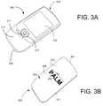
- FIG. 3Aillustrates a mobile computing device for use with one or more embodiments described herein.
- FIG. 3Bis an isometric rear view of the mobile computing device of FIG. 3A , according to one or more embodiments.
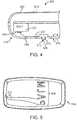
- FIG. 4is a side cross-sectional view of a housing of a mobile computing device, under an embodiment.
- FIG. 5is an isometric interior view of a lower shell or housing panel, constructed according to an embodiment.
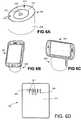
- FIG. 6Ais an isometric view of a docking station for use in mating with a mobile computing device such as shown and described, under another embodiment.
- FIG. 6B and FIG. 6Cillustrate a mobile computing device surface mounted to a docking station, under an embodiment.
- FIG. 6Dillustrates an alternative configuration for a back façade of a mobile computing device, under an embodiment.
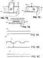
- FIG. 7A through FIG. 7Cillustrate an alternative construction and design for a docking station and a mobile computing device, according to an embodiment.
- FIG. 8Aillustrates a continuously conductive signal path used to convey only power from one device to another, under an embodiment.
- FIG. 8B and FIG. 8Ceach illustrate an embodiment in which both data and power are conveyed on a common continuously conductive signal path.
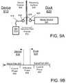
- FIG. 9Ais a simplified block diagram of a mobile computing device and docking station for conveying power or data signals inductively, under an embodiment.
- FIG. 9Billustrates an inductive signal path, as extended from or between a docking station and a mobile computing device, according to an embodiment.
- FIG. 10A through FIG. 10Cillustrates different coil distribution implementations for enabling inductive signal conveyance, under different embodiments or variations.
- FIG. 11Aillustrates a simplified block diagram of a computing system that provides for inductive conveyance of power and/or data signals, under an embodiment.
- FIG. 11Billustrates an alternative configuration for a docking station, as configured for use with any of the embodiments described above.
- FIG. 12describes a method for configuring operations of a mobile computing device when it is placed in contact with a docking station, according to an embodiment.
- FIG. 13is a block diagram that illustrates different data exchange operation that may be performed through pairing of docked devices, in accordance with one or more embodiments.
- FIG. 14illustrates a method in which an orientation of the mobile computing device is selectable to affect operations or functionality resulting from one or both docked devices, according to an embodiment.
- FIG. 15A through FIG. 15Cillustrate implementations of structural surface features that may be provided with the mobile computing device and/or the docking station, under different embodiments of the invention.
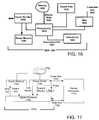
- FIG. 16is a simplified block diagram of a mobile computing device, in accordance with one or more embodiments.
- FIG. 17is a simplified block diagram of a mobile computing device configured to have a signal handing resource that is capable of receiving and/or communicating signals through an inductive signal path, under an embodiment.
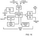
- FIG. 18is a simplified block diagram of a docking station, in accordance with one or more embodiments.
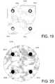
- FIG. 19depicts a configuration for a back face of a mobile computing device, under an embodiment.
- FIG. 20depicts a top view of a receiving surface for a docking station that includes an arrangement of magnets, under an embodiment.
- FIG. 21is a side cross-sectional view of a docking station with magnets for providing a magnetized receiving surface, under an embodiment.
- FIG. 22illustrates one embodiment in which an arrangement of ferrous cups are provided for use with one or more magnets of the docking station, under an embodiment.
- FIG. 23illustrates an embodiment in which a relative geometry of magnets and tabs may be offset to create a magnetic locking effect between docked devices, according to another embodiment.
- FIG. 24shows another embodiment in which a square magnet is provided on the receiving surface in order to constrain a slightly smaller round tab, according to another embodiment.
- FIG. 25depicts a façade of the mobile computing device with representative electronic components, according to an embodiment.
- FIG. 26depicts the back façade of the mobile computing device with an enhancement for device orientation detection.
- FIG. 27shows a front façade of a docking station with slugs, according to an embodiment.
- FIG. 28 and FIG. 29illustrate side views of how a docking station can be configured in positioning a set of slugs with respect to a receiving surface, under an embodiment.
- FIG. 30illustrates a ferrous ring formed into a region of the back façade of a mobile computing device, under an embodiment.
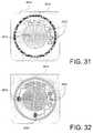
- FIG. 31illustrates a ferrous ring about a back façade of a mobile computing device with one or more other components, under an embodiment.
- FIG. 32illustrates a ferrous ring about a back façade of a mobile computing device with one or more other components, including an orientation detector, under an embodiment.
- FIG. 33illustrates a mobile computing device docked onto a docking station (or other device) using magnetic clasping, under an embodiment.
- FIG. 34Aillustrates a perspective view of a ring interface for a magnetic clasp, according to an embodiment.
- FIG. 34Billustrates a perspective view of a ring interface with mechanically proud areas, according to an embodiment.
- FIG. 35illustrates an embodiment of a magnetic element which may be used for the magnetic clasping as described in any of the above embodiments
- FIG. 36illustrates a cross-sectional view of another embodiment in which a mobile computing device is docked to a docking station or other device through use of magnetic clasping.
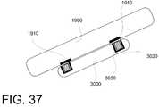
- FIG. 37illustrates an embodiment in which a mobile computing device magnetically couples to a sticky-back accessory device other than a docking station, under another embodiment of the invention.
- Embodiments described hereinprovide a framework by which two or more computing devices (e.g. mobile computing device and/or docking station) are enabled to transfer power and/or data signals without use of exterior connectors (i.e. is ‘connector-less’).
- computing devicese.g. mobile computing device and/or docking station
- Specific implementation scenariosinclude two computing devices being brought into contact or proximity for purpose of at least one device signaling power and/or data to the other device using a ‘connector-less’ signal exchange.
- more than two devicesmay be connected or placed in contact with one another to receive or provide power signals and/or data.
- a mobile computing device‘MCD’
- docking station‘dock’
- features and componentsthat enable charging/power signals to be communicated from the dock to the MCD without use of connectors.
- the dock and/or MCDmay exchange or transmit data signals to the other device when the MCD is retained against the dock (i.e. ‘docked’).
- an embodimentprovides for a mobile computing device that includes an inductive element and a signal handling module or component.
- the signal handling moduleis configured to inductively receive at least one of a power or data signal from another device using the inductive element.
- a mobile computing devicemay include a housing shell that defines at least a portion of an exterior of device.
- One or more conductive elementsmay be provided on the exterior without a connector structure on the exterior as part of the shell.
- the one or more conductive elementsmay form at least a portion of a conductive path that passes through a thickness of the shell and extends into the recharging circuit.
- a signal handling resource or modulemay be provided that receives one or more signals communicated from another device to the mobile computing device using the one or more conductive elements.
- the one or more signalsmay carry both power and data.
- a computing systemin another embodiment, includes a mobile computing device and an accessory device.
- the mobile computing deviceis configured to inductively transmit or receive at least one of a power or data signal.
- the accessory deviceis configured to inductively communicate with the mobile computing device in order to transmit or receive the at least one power or data signal.
- an accessory device for a mobile computing devicemay include one or more inductive elements, and a signal handling module that is configured to inductively transmit at least one of a power or data signal to another device using the inductive elements.
- a mobile computing deviceand a docking station are provided.
- the docking stationis configured to (i) physically retain the MCD, and (ii) communicate one or more signals to the MCD when the MCD is retained.
- the docking stationis structured to enable the MCD to occupy any one of a plurality of orientations when the MCD is retained on the docking station.
- at least one of the MCD or docking stationis structured to identify an orientation of the MCD as retained on the docking station.
- At least one of the MCD or the docking stationis configured to perform one or more operations that are selected, by either the docking station or the MCD, based at least in part on the identified orientation of the MCD.
- a computing systemcomprising a mobile computing device and an accessory device may be magnetically clasped to one another.
- at least one of the mobile computing device or accessory deviceincludes a magnetic component to retain the other of the mobile computing device or accessory device in one or more orientations.
- Numerous embodiments described hereinprovide for magnet-oriented configurations, and use of magnets to enable multiple orientations of a device in a docked position.
- a MCDmay correspond to a wireless telephony and/or messaging device, a media player, a camera or video recorder, a microphone, a multi-function device, a personal digital assistant or ultra-MCD (e.g. fully functioning handheld device), a global positioning device or some other kind of device.
- Wireless telephony/data devicesmay include cellular devices or even voice-over-Internet Protocol devices (such as those that use Wireless Fidelity “WiFi”). Numerous types of devices and form factors may be included with embodiments described herein.
- each connector structurenormally has a physical structure or layer formed from insulative material that serves to retain and position electrical elements that are conduits for signals.
- the physical structuresinclude male/female retention features.
- Connectorsmay be mated by inserting the male retention features into aligned corresponding features.
- numerous embodiments described hereinenable two devices (e.g. mobile computing device and docking station) to exchange power or data using a “connector-less” scheme.
- the connector-less schememay provide conductive or transductive signal paths for carrying power and data.
- devicesincorporate electrical elements that do not require placement of electrical contacts in a separate physical layer apart from the housing of the device.
- the connector-less schemes described with embodimentsenables the exchange of power or data amongst coupled devices without need to accommodate separately defined structures for connector elements, physical layers, insertive male/female structures or the like.
- One or more embodiments described hereininclude computing system that includes a mobile computing device and an accessory device.
- the mobile computing devicemay be configured to inductively transmit or receive at least one of a power or data signal.
- the accessory devicemay be configured to inductively communicate with the mobile computing device in order to transmit or receive the at least one power or data signal.
- a mobile computing devicecomprising includes an inductive element, and a signal handling module that is configured to inductively receive at least one of a power or data signal from another device using the inductive element.
- an embodimentincludes an accessory device for a mobile computing device.
- the accessory devicemay include an inductive element, and a signal handling module that is configured to inductively transmit at least one of a power or data signal to another device using the inductive element.
- the signal handling module or resourcecombines with the inductive element to communicate the power signal and to modulate the power signal to carry data.
- the accessory devicemay include a first coil to inductively signal at least power to the other device, and a second coil to inductively signal at least data to the other device.
- the accessory devicemay further include a receiving surface to receive the device on its façade.
- the accessory deviceis configured to signal the power or data signal when the other device is received on the receiving surface.
- the MCD and the docking stationare both configured to perform one or more operations based at least in part on the identified orientation.
- the docking stationmay include a receiving surface that is structured to retain the MCD in any one of the plurality of orientations.
- the docking stationmay include a receiving surface that is structured to retain the MCD in any one of the plurality of orientations.
- the docking stationmay be structured to enable a user to alter the orientation of the MCD when the MCD is retained on the receiving surface.
- a docking stationmay be configured to include one or more mechanical retention features that are provided on the receiving surface to retain the MCD in any one of the plurality of orientations.
- the MCDmay include a housing having a rear façade that is structured to be received and retained on the receiving surface of the docking station.
- the docking stationmay include one or more structural template formations provided with the receiving surface.
- the MCDmay include a housing that is structured to be received and retained by the template formations provided with the receiving surface.
- the MCDincludes a housing having one or more metallic or magnetic components distributed on a surface that is to be placed in contact with the receiving surface.
- the docking stationincludes one or more magnets that are provided on the receiving surface to retain the MCD in any one of the plurality of positions.
- At least one of the docking station and the MCDare configured to detect a characteristic or property of a magnetic field that is generated from the docking station and affected by the orientation of the MCD in order to determine the orientation of the MCD.
- a docking stationmay be equipped with one or more of (i) an accelerometer and/or (ii) an optical sensor in order to identify the orientation of the MCD.
- the docking stationmay be equipped with magnetic reed and/or Hall effect switches to identify the orientation of the MCD.
- one of the MCD or the docking stationmay be structured to identify the orientation of the MCD and to communicate information that identifies or uses the identified orientation to the other of the MCD or docking station.
- the MCDincludes a sensor to determine orientation information about how the MCD is oriented at a given instance.
- a processor of the MCDmay use the orientation as determined from the sensor to identify the orientation of the MCD when the MCD is retained on the docking station.
- a docking station for a mobile computing deviceincludes a receiving surface that is structured to receive and retain a facade of the mobile computing device.
- the docking stationmay also include a configuration of electrical contacts distributed on the receiving surface to make contact with the facade of the mobile computing device.
- the configuration of electrical contactsmay include two or more electrical contacts that are each positioned to make contact with the corresponding electrical contact on a surface or facade of another device.
- a signal handling componentmay be configured to transmit one or more signals that carry both power and data using electrical contacts distributed on the receiving surface.
- a mobile computing devicemay include a housing and a signal handling component.
- the signal handling componentmay be contained within the housing.
- a docking stationmay include a surface to receive the mobile computing device.
- the docking stationmay include a signal handling component.
- each of the mobile computing device and the docking stationinclude one or more components to enable communication of one or more signals that carry both power and data using a signal path that (i) has no insertive connectors, and (ii) extends between the signal handling component of each of the mobile computing device and the docking station.
- the housing of the MCDincludes multiple electrical elements distributed on a rear façade of the housing.
- the multiple electrical elementseach form a part of a shell that comprises the housing.
- the docking stationinclude a pattern of corresponding electrical elements provided on the receiving surface. At least some of (i) the multiple electrical elements of the MCD, and (ii) the pattern of corresponding electrical elements on the receiving surface of the docking station, align to make electrical contact to form the one or more continuously conductive signal paths that pass through a thickness of the housing of the MCD.
- At least one of the MCD or docking stationis structured to identify the orientation of the mobile computing by identifying which of (i) the multiple electrical elements of the MCD, and (ii) the pattern of electrical elements on the receiving surface, are in electrical contact.
- the MCD and the docking stationare configured to communicate one or more signals using one or more signal paths that are at least partially inductive as between the MCD and the docking station.
- the one or more signalsmay include a power signal so that the docking station supplies power to the MCD.
- an embodimentprovides that least one of the MCD or docking station is structured to identify an orientation of the MCD using a reflected load present on the inductive portion of the signal path.
- the docking stationis signaled to couple to one of two or more connected devices.
- the one of two or more connected devicesis selected by either of the MCD or docking station based on the identified orientation of the MCD on the receiving surface of the docking station.
- magnetic couplingmay be used between the MCD and the accessory device in the context of assigning orientation-dependent functionality or settings between the two devices.
- the magnetic componentcorresponds to one or more magnets provided with or beneath the receiving surface of the docking station.
- Ferrous materialmay be provided on the rear facade of the mobile computing device as a plurality of tabs, One or more of the tabs may be non-circular, so that at least a first of the one or more magnets is circular.
- the first tabmay be positioned to magnetically couple to the first magnet.
- the magnetic component or couplingmay correspond to one or more magnets provided with or beneath a receiving surface of the docking station.
- the ferrous materialmay be provided on the rear facade of the mobile computing device as a plurality of tabs.
- one or more of the tabsmay be circular, and at least a first of the one or more magnets is non-circular.
- the first tabmay positioned to magnetically couple to the first magnet.
- At least one of the mobile computing device or accessory deviceincludes one or more magnets to (i) retain the other of the mobile computing device or accessory device in a plurality of discrete orientations, and (ii) to repel the other of the mobile computing device or accessory device from being retained in any orientation other than the plurality of discrete positions.
- At least one of the mobile computing device or accessory deviceincludes one or more magnets to retain the other of the mobile computing device or accessory device in 2 or 4 discrete orientations.
- At least one of the mobile computing device or accessory deviceis pre-configured to operate (i) in a first state when the mobile computing device has a first one of the plurality of discrete orientations, (ii) in a second state when the mobile computing device has a second one of the plurality of the discrete positions.
- an accessory devicefor a mobile computing device.
- the accessory deviceincludes a body that extends to a receiving surface.
- Magnetic materialmay be provided at one or more locations on the receiving surface.
- the magnetic materialmay be distributed to enable the receiving surface to retain a particular mobile computing device having magnetically attracted material provided with at least a portion of the housing.
- Some embodiments described hereinmay be implemented using programmatic elements, often referred to as modules or components, although other names may be used. Such programmatic elements may include a program, a subroutine, a portion of a program, or a software component or a hardware component capable of performing one or more stated tasks or functions.
- a module or componentcan exist on a hardware component independently of other modules/components or a module/component can be a shared element or process of other modules/components, programs or machines.
- a module or componentmay reside on one machine, such as on a client or on a server, or a module/component may be distributed amongst multiple machines, such as on multiple clients or server machines.
- Any system describedmay be implemented in whole or in part on a server, or as part of a network service.
- a systemsuch as described herein may be implemented on a local computer or terminal, in whole or in part.
- implementation of system provided for in this applicationmay require use of memory, processors and network resources (including data ports, and signal lines (optical, electrical etc.), unless stated otherwise.
- Some embodiments described hereinmay generally require the use of computers, including processing and memory resources.
- systems described hereinmay be implemented on a server or network service.
- Such serversmay connect and be used by users over networks such as the Internet, or by a combination of networks, such as cellular networks and the Internet.
- networkssuch as the Internet
- one or more embodiments described hereinmay be implemented locally, in whole or in part, on computing machines such as desktops, cellular phones, personal digital assistances or laptop computers.
- memory, processing and network resourcesmay all be used in connection with the establishment, use or performance of any embodiment described herein (including with the performance of any method or with the implementation of any system).
- Some embodiments described hereinmay be implemented through the use of instructions that are executable by one or more processors. These instructions may be carried on a computer-readable medium.
- Machines shown in figures belowprovide examples of processing resources and computer-readable mediums on which instructions for implementing embodiments of the invention can be carried and/or executed.
- the numerous machines shown with embodiments of the inventioninclude processor(s) and various forms of memory for holding data and instructions.
- Examples of computer-readable mediumsinclude permanent memory storage devices, such as hard drives on personal computers or servers.
- Other examples of computer storage mediumsinclude portable storage units, such as CD or DVD units, flash memory (such as carried on many cell phones and personal digital assistants (PDAs)), and magnetic memory.
- Computers, terminals, network enabled devicesare all examples of machines and devices that utilize processors, memory, and instructions stored on computer-readable mediums.
- FIG. 1is a representative diagram illustrating two computing devices that can be brought into contact for purpose of enabling one device to provide a power and/or data signal to the other device, according to an embodiment of the invention.
- Numerous embodiments described herein, including an embodiment such as described with FIG. 1reference a MCD and dock as two devices that are brought into contact with one another for purpose of power/data transfer without use of traditional insertive or mechanically coupled connectors.
- different kinds of devicese.g. portable devices and accessory devices
- the two devicesmay correspond to, for example, a MCD and an accessory device for the MCD.
- the MCDis a multi-purpose device having cellular data and telephonic capabilities
- the accessory devicecorresponds to, for example, a docking station (for communications and power supply), sticky (or piggy)-back accessory, a light projector, a speaker set, or headset station.
- the MCDmay include, for example, functionality for use as a media player, a camera or video recorder, a global positioning unit, an ultramobile personal computer, a laptop computer, or a multi-purpose computing device. Numerous other examples and implementations are described herein, including embodiments in which three or more devices are interconnected through one or more connector-less connections.
- a system 100includes a MCD 110 that is supported or otherwise retained by a dock 120 .
- the manner in which the MCD 110 is supportedmay vary.
- the orientation of the MCD on the dockmay be changed by the user for purpose of configuring operations or behavior of one or both devices.
- the MCD 110is supported on the dock 120 in a partially upright position along its length axis (L).
- Such an orientationmay correspond to a ‘portrait’ position.
- the ‘landscape’ positions, or positions in between the portrait and landscape positionsmay be possible.
- the dock 120utilizes physical support structures (not shown), such as shelves, platforms, hooks or mechanical retention features, to retain the MCD 110 in a docked or mated position.
- physical support structuressuch as shelves, platforms, hooks or mechanical retention features
- magnetic claspsmay be included or provided the dock 120 and/or the MCD 110 to secure retention of the MCD against the dock.
- the dock 120may include resources 121 for generating or extending power and/or data signals to the MCD 110 .
- the dock 120may be mated with a power outlet 124 or another computer 126 (e.g. desktop computer) to extend power and/or data signals.
- the resources 121may include circuitry or hardware, such as AC/DC converters and regulators.
- the dock 120may include a physical connector port, such as provided by a Universal Serial Bus (USB) connector.
- USBUniversal Serial Bus
- the dock 120may include data acquisition capabilities, provided through connector ports with the computer 126 , wireless ports (e.g. cellular, WiMax connection, Bluetooth), Internet ports, and media feeds (e.g. provided through television tuner and cable).
- the MCD 110has a housing shell 112 having a thickness (t).
- the housing shell 112may be used to retain internal components of the MCD 110 , such as a circuit board, processor, memory, or components of a display assembly.
- the MCD 110may be structured so that a primary facade 115 (e.g. the back panel) of the housing shell 112 rests on a receiving surface 125 of the dock 120 .
- the MCD 110 and dock 120are electrically mated without use of connector structures.
- one or more signal paths 132is defined by conductive or current-carrying elements that are distributed in the dock 120 and the MCD 110 .
- the signal path(s) 132is continuously conductive in carrying one or more signals (e.g. power and/or data) between the dock 120 and the MCD 110 .
- the signalmay extend through the housing shell 112 (and its thickness) and from/to a recharging module 118 or circuit of the MCD 110 .
- Such a power signalmay be delivered from the dock 120 to the MCD 100 for the primary purpose of recharging a battery module 119 on the MCD.
- the power signalmay be delivered from the MCD 110 outward.
- the signal path(s) 132carry data
- the signalmay be delivered or exchanged between data handling resources of each device.
- the MCD 110may be equipped with data receiving elements 113 (or alternatively, a communication port) provided inside or with the thickness of the housing 112 .
- the processor(not shown) may interconnect to the data receiving elements 113 or communication port provided interior to the housing 112 to process and use the data signal.
- the data signalmay be delivered outward from the MCD 110 to the accessory device (which does not necessarily have to be the dock) in a similar manner.
- Various types of data handling resourcesmay be provided on the dock 120 in order to communicate data out or receive data in.
- Such componentsmay include a processor, storage resource, or physical/logical communication port to another device or medium.
- the dock 120may enable synchronization of data files and/or records between a third computer (e.g. personal computer 126 ) and the MCD 110 .
- the signal path 132 that is enabled from the construction of the MCD 110 and dock 120is inductive or transductive.
- the signal path 132may use induction or other transduction to convey signal energy from or between respective signal points of the dock 120 and the MCD 110 .
- the non-continuously (or transductive) signal pathmay be used to carry power and/or data, to and/or from the MCD 110 or dock 120 .
- FIG. 2Ais a representative block diagram of a computer system comprising the MCD 110 and dock 120 , each of which is configured to communicate signals on a continuously conductive signal path, under an embodiment.
- the MCD 110 and dock 120may be mated and retained in a manner described with an embodiment of FIG. 1 .
- An exterior surface 212 , 222 of MCD 110 and dock 120respectively may be in contact as a result of the retention of the MCD on a receiving surface of the dock.
- the exterior surface 212 of MCD 110may correspond to, or be provided by, the exterior facade of the housing shell 112 ( FIG. 1 ).
- a signal source 225 on the dock 120e.g. such as a power outlet 124 in combination with resources 121 ) may generate a signal (e.g.
- the exterior surface 212 of the MCD 110includes conductive elements 214 that extend through the thickness of the housing shell and onto a charging circuit or module 230 .
- the design of the dock 120 and/or how it receives MCD 110may be configured to provide active or inherent retention features that force contact between conductive elements 214 and 224 on respective exterior surfaces 212 , 222 of the dock 120 and the MCD 110 (at least when properly positioned).
- retention featuresmay correspond to magnetic clasps, or to mechanical features such as platforms, ledges or surface features.
- coupling featuressuch as biased insertion members (e.g. on the dock 120 ) and receiving holes (e.g. on the MCD 110 ) may also be used.
- the dock 120may be constructed to receive the MCD 110 in a manner that orients the MCD 110 so that gravity forces its exterior surface 212 down into contact with the receiving surface 222 of the dock.
- the retention featuresenable the user to select and to change an orientation of the MCD 110 when retained on the dock 120 .
- the signal exchanged via the continuously conductive signal pathis for power.
- the dock 120connects to a power source 252 (e.g. outlet 124 , personal computer 126 ) and becomes a source of power for the MCD 110 .
- the power signal path initiated by the dock 120may be in the form of a closed circuit, requiring positive and negative polarity connection points with the MCD 110 .
- two separate pairs of conductive elements 214 , 224(or set pairs) may be provided for purpose of conveying power, with each pair of conductive elements 214 , 224 providing a polarity in the connection.
- one or more contact pointsmay be used to carry one or more signals.
- two or three signalsmay be conveyed between the devices.
- some embodimentsalso provide for an integrated power and data signal, so that power and data are carried on one path and at the same time.
- FIG. 2Bis a representation of one or more continuously conductive signal path 250 , as extended from or between the dock 120 to the MCD 110 , using conductive elements provided on both devices (such as described with previous embodiments).
- the signal paths 250may carry power and/or information from the dock 120 to the MCD 110 , or alternatively, from the computing device to the station.
- the signal paths 250when provided in the form of power, may be generated from electrical power source 252 and signaled out using conductive elements.
- the circuit elements provided from the dock 120include wiring or circuit elements that terminate as conductive elements 224 on the exterior surface 222 ( FIG. 2A ).
- the conductive elements 224may correspond to, for example, metallic elements that terminate electrical leads from a power source 252 of the dock 120 .
- the continuously conductive signal path 250may extend to the conductive elements 214 on the exterior surface 212 ( FIG. 2A ) of the MCD 110 , which act as terminals for receiving the power signal from the dock.
- the conductive elements 214 of the MCD 110may extend through the thickness of the housing shell 112 ( FIG. 1 ) to the charging circuit or module (or alternatively, some other signal handling component).
- the conductive elements 214 on the exterior surface 212 ( FIG. 2A )may thus form positive and negative terminals for receiving corresponding connections with conductive elements of the dock 120 .
- FIG. 3Aillustrates a MCD configured to enable a conductive and connector-less connection with an accessory device, under an embodiment.
- the MCD 300corresponds to a cellular telephony data device, such as a so-called “Smart phone” or “mobile companion”.
- Such devicesuse cellular networks to enable telephony operations, messaging (e.g. e-mail, instant messaging, Short Message Service (SMS), Multimedia Message Service (MMS)) and Internet browsing or other network operations.
- SMSShort Message Service
- MMSMultimedia Message Service
- such devicesmay enable network connectivity through alternative wireless network mediums, such as Wireless Fidelity (or ‘WiFi’) as provided under standards such as those set forth by IEEE 802.11(b) or (g).
- WiFiWireless Fidelity
- embodiments described hereinfocus on cellular telephony data devices, other types of computing devices may also be used with embodiments described herein, such as multimedia devices, ultramobile personal computers, GPS units, or cameras/video recorders.
- the MCD 300includes a housing 310 have a front facade 313 that opposes a back or rear facade 315 ( FIG. 3B ).
- the front facade 313typically incorporates user-interface features, such as a display 316 , buttons or touch-sensitive features 317 , as well as any one of many possible other features, such as 5-way navigation mechanisms (with four way scrolling and center select), keypads or keyboards, microphones, dials, and camera lenses and numerous other features.
- Conventional devicesoften incorporate physical connectors into a peripheral edge 309 (e.g. such as USB or micro-USB ports), for purpose of performing battery recharge or data transfer/exchange. In contrast, it is possible for embodiments described herein to include no such physical connector ports to perform recharge or data transfer functions.
- FIG. 3Bis an isometric rear view of the MCD of FIG. 3A , under an embodiment.
- the housing 310may be provided as a shell that encompasses the rear facade 315 .
- the housing 310is structured to enable use of a continuously conductive signal path that may be communicated from (or to) another device (e.g. dock) that is brought into contact with the MCD.
- housing 310 of a MCD 300is structured to include conductive elements 302 that connect with designed conductive elements 422 (e.g. see FIG. 6A ) of a dock 400 ( FIG. 6A ).
- the conductive elements 302extend a thickness into the shell of the housing 310 and electrically connect to a recharging circuit or power module (not shown in FIG. 3 ) of the MCD 110 ( FIG. 1 ).
- a recharging circuit or power modulenot shown in FIG. 3
- the connector-less featuresenable the exchange of signal paths for both power and data, without requiring, for example, connector physical layers, apertures to receive insertive elements from the connecting device, or conductive extension elements.
- strategically positioned conductive elements 302may be provided on a facade 315 of the housing 310 .
- these conductive elementsmay be incorporated into a mid-region 308 of the facade 315 , or at least apart from the edges 311 or facade boundaries of the housing 310 , where conventional connector elements are provided.
- the conductive elements 302are integrated to appear as aesthetic or design elements.
- the conductive elements 302are integrated into a logo 304 that appears on the back facade 315 .
- one letter of a logomay provide a positive terminal for receiving a power signal, while another letter of a logo may provide a negative terminal.
- the combination of positive and negative terminalsmay create a power signal that extends from the dock 120 (see FIG. 1 ) to the MCD 300 .
- additional conductive elementsmay be used to carry data and information.
- another of the letters in the logomay correspond to a logo that is positioned to receive or provide a data signal.
- FIG. 4is a side cross-sectional view of the housing 310 of the MCD 300 , under an embodiment.
- the housing 310may be provided by an upper shell 362 and a lower shell 364 .
- the upper shell 362may provide the front facade 313
- the lower shellprovides the rear facade 315 .
- the shells 362 , 364may be sealed to complete the housing 310 .
- the housing 310may be characterized by a thickness t.
- the housing 310may be structured to assume any one of a pre-designed form factor, with contours or design parameters that meet design parameters.
- the conductive elements 312may be inserted into openings 323 or otherwise integrated into the facade 315 so as to provide conductive surface points 325 in a mid-portion of the facade 315 .
- the conductive surface points 325may correspond to bumps or other surface features, or alternatively be smooth from a tactile perspective.
- a conductive medium 332e.g. plate, cable, lead lines
- the conductive medium 332is provided in a region of the lower shell that corresponds to a battery cover.
- the terminationmay be provided by connector elements, such as pogo pin termination points 335 .
- the pogo pin termination points 335may mate or connect with corresponding receiving elements of the battery module 370 of the MCD 300 when the battery cover is closed, or when pressure is applied to the battery cover (such as when the back façade 315 is rested on the receiving surface of the dock).
- a power circuit for carrying a power signal from the dock 120 ( FIG. 1 ) to the MCDis created and effective under conditions of (i) receiving a power signal, and (ii) having the battery cover pressed on the docking station.
- FIG. 5is an isometric interior view of the lower shell 364 (or portion thereof, such as the battery cover) which provides at least a portion of the exterior rear facade 315 ( FIG. 3B ), according to an embodiment.
- conductive plates or leads 332may extend from selected logo elements 304 which are integrated or otherwise formed on the exterior of the lower shell 364 .
- the leads 332may extend to a point coinciding with positioning of the battery module 370 ( FIG. 4 ) so that a resulting power signal carried between the dock 120 (see FIG. 1 ) and the MCD 300 (see FIG. 1 ) may recharge the battery element of the device.
- the conductive surface points 325e.g. see FIG.
- an embodimentmay appear as elements of a logo on the rear facade (e.g. see FIG. 4 ).
- an embodimentassigns one logo element 304 to act as a positive terminal and another logo element 304 to act as a negative terminal.
- a power circuitmay be created and shared between the MCD 300 and the dock (or other device) for purpose of recharging the batter module 370 on the MCD.
- the same constructionmay be used to enable reversal of the power signal out of the device.
- the power signalmay use the battery module 370 of the MCD as the source in order to signal out the power and/or charge to an accessory device in contact with the rear facade 315 .
- a dockmay be structured to provide conductive elements that are selectively positioned or formed to mate with corresponding conductive elements of the MCD 300 (see FIG. 3 ).
- a dock for supporting the MCD in a manner as describedmay have any of many possible form factors.
- the dockmay extend an arrangement of contact elements that are aligned to make contact surface points 325 on the rear facade 315 of the MCD 300 ( FIG. 3B ).
- FIG. 6Ais an isometric view of a dock for use in mating with a MCD such as shown and described other embodiments.
- dock 400includes a body 405 which extends a height from a support surface (e.g. ground or table-top) and enables support of the MCD 300 ( FIG. 3B ) in an upright or partial upright position.
- the dock 400includes a receiving surface 410 which supports the MCD on its back facade 315 , so that the device can be viewed face-up when retained on the body 405 .
- the body 405vertically slants the receiving surface 410 on which the MCD 300 (shown in FIG. 3B ) may rest and/or be held in position.
- magnetic retention featuresmay be incorporated into the receiving surface 410 and/or device housing 310 ( FIG. 3B ).
- a shelfmay be positioned at the gravitation bottom of the slanted surface.
- Other mechanical or magnetic retention mechanismsmay alternatively be employed.
- the receiving surface 410may be horizontal or provided with other retention mechanisms to hold the device in place when it is rested on the receiving surface.
- retention featuressuch as magnetic clasps
- embodimentsinclude different patterns or arrangements for the manner in which conductive elements 422 on the receiving surface 410 of the dock are provided.
- the conductive elements 422 of the dock 400are provided in a circular and concentric arrangement, although alternative arrangements may be employed.
- an outer ring 431may provide one terminal for a power signal, while an inner ring 433 may provide the opposite pole.
- Each ring 431 , 433may be spaced from one another so that when the MCD is positioned on the receiving surface 410 , the conductive elements on 315 ( FIG. 3B ) the façade of the MCD 300 (see FIG. 3B ) will contact the correct ring, regardless of whether the MCD is in the portrait or landscape (or in between) orientation when retained on the receiving surface.
- the devicemay have anyone of a plurality of positions on the receiving surface 410 .
- the positionsmay be discretely defined positions (e.g. north, south, east or west) or continuous on a ring or arc.
- the receiving surface 410is magnetized.
- the use of magnetic forcesmay be accomplished by integrating one or more magnetic elements into the body 405 , so that the magnetic field emits outward from the receiving surface.
- the magnetic fieldsmay attract to elements on the MCD 300 , such as the conductive elements 302 ( FIG. 3B ) or conductive plate 332 ( FIG. 4 ) of the MCD.
- FIG. 6B and FIG. 6Cshow the MCD 300 surface mounted to the dock 400 .
- the MCD 300may be surface mounted in either portrait ( FIG. 6B ) or landscape ( FIG. 6C ) orientations. More orientations are possible, depending on the manner in which the MCD 300 is retained.
- the magnetic forcesenable the MCD 300 to be positionable on the receiving surface 410 ( FIG. 6A ) in a discrete number of positions.
- the magnetic forcesmay be configured to enable the MCD 300 to occupy portrait or landscape positions, as shown by FIG. 6A or FIG. 6B .
- one of four possible positionsmay be possible, including opposite portrait and landscape orientations (i.e. north, south, east and west).
- positions in between those specified positionsmay be repelled.
- magnetic forcesmay be used to create a defined number of possible orientations by which the MCD 300 may be oriented with respect to dock 400 .
- the dock 400may be configured to enable the MCD to have any one of a plurality of positions defined anywhere along an arc.
- the device 300may include a ring of ferrous material that enables it to occupy positions on an arc, rather than be repelled from defined orientations. Numerous further variations are possible and some are described in greater detail below.
- Another embodimentmay surface treat conductive elements 422 ( FIG. 6A ) or other portions of the façade of the MCD.
- FIG. 6Dillustrates an alternative configuration for a back façade of MCD, under an embodiment.
- an arrangement of electrical contacts 680is shown to form a logo 682 for the back façade 315 of the MCD.
- the logo 682may comprise multiple letters, each of which is termed a logo element 681 .
- each logo elementmay comprise of multiple pins, or pogo pins that form an electrical connection. Such a formation of electrical contacts or pins is referred to as a “Bed of Nails” configuration.
- each logo element 681carries a signal path.
- the logo elements 681combine to include a positive and ground signal and two data signals (+ and ⁇ ).
- Individual elementsi.e. logo elements 681
- a logo elementmay include one or two pins provided on length portions of the element.
- Various other pin configurationsare contemplated.
- At least some of the electrical contacts 680are pogo-pins that insert inward to a conductive element (not shown) that is common to all the pogo-pins in that logo element 681 .
- a conductive elementnot shown
- at least some electrical contacts 680 of individual logo elements 681move inward to form a conductive connection with corresponding electrical elements on the dock. This configuration for the back façade may enhance the conductive electrical connection where the contacts 680 meet the corresponding elements on the receiving surface of the dock.
- electrical contacts formed on the rear façade 315 of the MCD 300may be combined with electrical contacts formed on the rear façade 315 of the MCD 300 .
- the electrical contacts on both the rear façade 315 and the dockmay be surface treated to be rough in order to facilitate retention of the MCD in the docked position.
- FIG. 6Dillustrates use of logo elements
- the pogo elements that provide the conductive surfacesmay be provided in various geometric shapes (e.g. circles) or blended by color or appearance with the housing of the MCD.
- FIG. 7A through FIG. 7Cillustrate an alternative design for the dock and MCD, under another embodiment.
- the dock 500includes an elevated platform 708 that serves as a support structure for the MCD 300 .
- a contact surface 710 on which the conductive elements is providedmay extend vertically from the platform 708 .
- a pair of contact elements 702 representing positive and negative contact points for an emitted power signalmay be provided on the contact surface 710 .
- FIG. 7Billustrates the MCD 300 surface mounted on the dock 500 in a portrait mode.
- the platform 708may support the MCD 300 in the upright position.
- the MCD 300may be moved into a landscape position and supported by the platform 708 .
- the contact elements 702may remain in contact with the contact surface points 325 ( FIG. 3B ) on the rear facade 315 ( FIG. 3B ) of the MCD 300 when the MCD has either the landscape or portrait positions on the dock.
- a continuously conductive signal pathsuch as described with FIG. 2A and FIG. 2B may be used to convey power and/or data.
- FIG. 8Arepresents a continuously conductive signal path used to convey only power from one device to another.
- the continuously conductive signal pathsconvey power from a dock 400 ( FIG. 6A ) to a MCD 300 ( FIG. 3A ).
- the continuously conductive signal pathsinclude positive and negative contact elements 702 , 704 .
- powermay be conveyed through electrical contact between two conductive elements on each of the dock 400 and the MCD 300 .
- FIG. 3Ain the case where two logo elements on a rear facade 315 of the housing 310 ( FIG. 4 ) are used to provide electrical elements, one logo element may represent the positive terminal and another logo element may represent a negative terminal.
- FIG. 8B and FIG. 8Ceach illustrate an embodiment in which both data and power are conveyed on a common continuously conductive signal path.
- an embodimentprovides for modulating a power signal 712 in a manner that enables the power signal to convey information.
- the dock 400may convey information to the MCD 300 using the same electrical contacts and signal that conveys power for operating components and/or recharging the device's battery.
- FIG. 8B and FIG. 8Cillustrates different types of modulation of signals that carry power. These types of modulations include (i) pulse-length modulation, where the positive power signals 712 is pulsed and modulated in length of time (see FIG. 8B ), (ii) frequency modulation of the positive power signal 722 (see FIG.
- the data that is conveyed through the power signalsis limited in quantity, as use of power signals to convey data has inherent limitations (e.g. noise, speed).
- the type of information that is conveyedis data for establishing subsequent local wireless communications.
- the power signalis used to initially pass credential or pairing information between devices.
- Such informationmay correspond to password, device identifiers, and other information that users often manually enter in order to enable, for example, BLUETOOTH pairing.
- the power signal conveyancemeans that two devices are placed in contact with one another by the user. The placement of the two devices in physical contact by the user may be viewed as a self-authenticating event. The event enables the assumption that the passing of credential information between the two devices is authorized or desired by the user.
- the conveyance of the power signalcoincides with automatic transmission of credential information.
- the dock 400FIG.
- the MCD 300may convey the credential information for enabling BLUETOOTH (or other standardized local wireless communications) to the MCD 300 (or vice-versa) ( FIG. 3A ).
- the MCD 300may use such credential information to establish a wireless pairing with the dock 400 (such as for BLUETOOTH or WIRELESS USB).
- other data and informationsuch as data corresponding to records or media, may be passed from the MCD to the dock 400 (or the reverse).
- While some embodiments described aboveprovide for a conductive signal path between a mobile computing device and a docking station, one or more embodiments provide a non-continuously conductive or transductive signal path to be used to carry power and/or information between the dock and the MCD.
- a non-continuously conductive signal pathmay refer to the ability of a signal to be carried from or between devices, where the signal undergoes transformation from current/voltage form to some other form and back again to current/voltage.
- One embodimentprovide for a signal path that includes an inductive segment to convey one or more signals between the MCD and the dock.
- FIG. 9A and FIG. 9Ban embodiment is illustrated in which the signal generated from either the dock 400 ( FIG. 6A ) or MCD undergoes transformation from a current/voltage form into an inductive or magnetic energy form, and then back into a current/voltage form.
- FIG. 9Ais a simplified block diagram of a MCD 810 and dock 820 , where one or both devices are configured to communicate signals on a signal path that has an inductive signal path portion, so as to form a partially inductive signal path 832 .
- the MCD 810may be placed in contact with the dock 820 , such as in a manner described with other embodiments (such as described with FIG. 1 ).
- a device exterior 808e.g. rear facade
- the two devicesmay be brought into close proximity, but not necessarily in contact, in order for inductive signal communication to take place.
- a signal source 824 on the dock 820may generate a signal 828 (e.g. power) that is transformed through a magnetic coil 826 or other inductive mechanism into a magnetic field.
- a corresponding coil 814 or inductive receiving componentmay be provided on the MCD 810 to transform the signal 828 into an electrical signal 816 .
- the electrical signal 816may be treated by various circuit elements and components in order to power components of the MCD 810 , and/or to charge a battery module 819 of the device 810 .
- FIG. 9Billustrates an inductive signal path 850 , as extended from or between the dock 820 to the MCD 810 , using a combination of magnetic/inductive and conductive elements provided on both devices.
- the signal path 850includes a current phase 852 and an inductive (or magnetic field) phase 854 .
- the inductive phase 854carries the signal across boundaries of respective housings using magnetic field.
- the signal path 850includes an inductive phase 854 , followed by a current phase 856 .
- the reverse pathmay also be possible, such as in the case when the MCD supplies power and/or data to the docking station or another accessory device.
- the inductive conveyance of power and/or data signalsmay be achieved through use of coils, provided on each device that is to be coupled to transmit or receive such signals.
- Various coil configurationsare possible to enable conveyance of power and/or data, either unidirectionally or bi-directionally.
- FIG. 10A through FIG. 10Cillustrate different coil distribution implementations for inductive signal conveyance, under different embodiments or variations.
- FIG. 10Aillustrates a computer system that includes two coils, one on each device.
- the two coils 902 , 904may be used to convey power and/or data in one signal 901 that is exchanged between the two devices.
- the conveyance of either power or datamay be bi-directional.
- FIG. 10Billustrates a three-coil implementation, where one of the two devices (e.g. the dock 820 ) includes two coils 912 , 914 , and the other device (e.g. MCD 810 ) includes just one coil 916 .
- the coil 916 of the MCD 810receives power 911 from one coil 912 on the dock, and data 913 from the other coil 914 .
- either the power 911 or the data 913 signalsmay be bi-directional, meaning the coil 916 on the MCD 810 may communicate the signals back to the dock 820 .
- the coil on the MCD 810signals data to the independent data coil on the dock 820 .
- FIG. 10Cillustrates another implementation in which each of the dock 820 and MCD 810 include two coils.
- power and data coils 922 , 924 on the dock 820may communicate power 921 and data 923 signals to respective coils 932 , 934 on the MCD 810 .
- the power and data communicationsare bi-directional.
- FIG. 11Aillustrates a simplified block diagram of a computing system that provides for inductive conveyance of power and/or data signals, under an embodiment.
- the computing system 1000includes MCD 1010 and dock 1020 (which may be equivalent to those devices shown in FIG. 3A and FIG. 6A respectively, or other embodiments described herein which provide for inductive signal transmission).
- the dock 1020includes a central processor 1024 , a power subsystem 1022 and a communication subsystem 1026 .
- the MCD 1010includes a power subsystem 1012 , a signal processor 1014 , and a communication subsystem 1016 .
- the MCD 1010(and optionally the dock 1020 ) include numerous other components, such as a central processor and memory resources for enabling application executions, cellular and data communications, and numerous other functions that are part of the usage of the MCD 1010 .
- the power subsystem 1022includes a connection to a continuous power supply 1021 , such as a wall outlet. Additionally, the power subsystem 1022 includes components for converting and regulating the signals from the power supply into a form that is suitable for conveyance using, for example, an inductive medium. Additionally, the power subsystem 1022 includes one or more coils for converting an electrical signal originating from the power supply 1021 into an inductive signal.
- the communication subsystem 1026may include wireless or wireline port(s) to receive and send data to other devices, including with other computers or data sources (e.g. media feeds from other devices, such as set-top boxes) or media output devices.
- the communication subsystem 1026also enables inductive data handling from data communicated by one of the inductive signal paths that extend between the two devices. As mentioned, such data may be conveyed by either modulating an inductive power signal or using a separate data signal path.
- the central processor 1024 of the dock 1020may be configured to handle incoming data signals from the communication subsystem 1026 , whether from the other resource or from the MCD 1010 . Additionally, the central processor 1024 may control data that is communicated out, either to the other resource or to the MCD 1010 (using the inductive signal path).
- the power subsystem 1012receives an incoming power signal 1008 from the dock 1020 and distributes the power signal in modified or regulated form to either other components or to the battery for recharge.
- the power signal 1008is signaled through an inductive path from the dock 1020 to the MCD 1010 , in a unidirectional fashion.
- the communication subsystem 1016is configured to communicate with the dock 1020 to receive and/or transmit data 1009 .
- the communication subsystem 1016may include resources to demodulate data carried on the power signal.
- the communication subsystem 1016may use its resources to implement a protocol for retrieving and using credential information (e.g.
- the protocolmay further provide for the communication subsystem 1016 to switch to, for example, a standardized wireless communication medium (e.g. BLUETOOTH) using the credential information and/or other data communicated by the power signal 1008 .
- another embodimentmay provide for the communication subsystem 1016 to be enabled to generate modulated power or other signals to communicate to the dock 1020 or other device.
- two coilsmay be used on the dock, including one coil that communicates both power and data and another that receives data from the MCD 1010 .
- the communication subsystem 1016may perform functions of both retrieving data from the modulated data signal and communicating data out to the data receiving coil on the MCD 1010 .
- datamay also be combined with the power signal 1008 by modulating the power signal.
- the dock 1020signals data with the power signal 1008 as a preliminary step to establishing a different wireless communication relationship.
- the data signal 1009may be communicated to or from the MCD separate from the power signal.
- transductive signal pathsmay use alternative signal carrier mediums.
- a transductive signal pathmay be formed by alternative mediums that carry power and/or data.
- Such other mediumscorrespond to (i) a light medium for carrying a portion of a power or data signal as light, (ii) an acoustic medium for carrying the signals as through acoustics.
- FIG. 11Billustrates an alternative configuration for a dock, as configured with any of the embodiments described above.
- a dock 1120may be configured to enable transmission of continuously conductive and/or transductive power or data signals to the MCD.
- the dock 1120is configured to include a receiving structure 1130 for an alternative device that can be used with the dock and/or the MCD.
- the receiving structure 1130corresponds to a slot for receiving a headset 1140 , such as a BLUETOOTH enabled headset for enabling hands-free telephony.
- an appropriately configured MCDmay be intermittently or selectively paired with the dock in order to enhance the functionality provided through one or both devices.
- the operability of the MCD, or applications that execute on the MCDmay be altered when the device is placed in contact with the dock.
- some datamay be exchanged through the physical contact of the MCD being placed in contact with the dock. This data exchange may enable, facilitate or enhance local wireless communication (or other communication mode) between the two devices.
- the orientation of the MCD on the dockmay be detectable, and used to enable or configure operations on one or both devices.
- FIG. 12describes a method for configuring operations of the MCD when it is placed in contact with the dock, according to an embodiment.
- a method such as describedmay be performed in whole or in part on a MCD such as described with any of the embodiments provided above.
- reference is made to elements shown with an embodiment of FIG. 11Aand such reference is intended to be illustrative of components that are suitable for performing a step or sub-step being described.
- one deviceperforms presence detection as to whether the two devices are placed in position to be docked.
- the MCD 1010may receive a power signal from the dock 1020 .
- such presence detectioncorresponds to either of the two devices being placed in contact with one another, so as to enable an inductive or conductive signal path (depending on the embodiment implemented) for the power signal.
- dockingmay be accomplished by two devices being brought in close proximity.
- inductive signal pathsare utilized, physical contact is not a requirement for presence detection.
- One or both devicesmay be configured to detect a signal resulting from, for example, the MCD 1010 being rested on the dock 1020 ( FIG. 13 ) in an orientation described with any of the other embodiments.
- the MCD 1010performs the initial detection and responds accordingly.
- the responsemay include communicating back to the dock 1020 ( FIG. 13 ) that the two devices are docked.
- either of the power or data signalsmay be received through use of a connector-less medium.
- sensors or other elementssignal separately the presence of the other device when the two devices are brought into contact.
- removal of the MCD 1010 from the docked positionmay also be detected. In one implementation, removal of the MCD 1010 from the dock 1020 may be detected by detecting a break in the incoming power signal.
- the MCD 1010configures its operations in a manner that recognizes the presence of the dock (i.e. ‘docking’ behavior).
- the MCD 1010may configure itself in a variety of ways. For example, similar to many conventional approaches, the device may suspend power-saving features or automatically perform data synchronization operations. As an addition or alternative to such configuration steps, the MCD 1010 may perform one or more sub-steps 1222 , 1224 and/or 1226 , as described below and elsewhere.
- sub-step 1222provides for performance of presence-centric functions and operations that utilize or combine the functionality, capabilities or access rights of the dock 1020 .
- presence-centric functions and operationsenable the MCD 1010 to prioritize settings or modes of use based on detecting presence of the dock 1020 .
- the MCD 1010performs functions and operations (including mode settings) based on detecting removal of the MCD 1010 from being in contact with the dock 1020 .
- the dock 1020may provide access to other resources (e.g. other computers, media devices etc.) and the act of the MCD 1010 docking with it serves as authorization for the MCD to access or use the extended resources provided by the dock 1020 .
- the following usage scenariosprovide examples of how sub-step 1222 may be implemented.
- the MCD 1010may be configured to enable telephony operations, including enabling the user to answer incoming calls through manipulation of anyone of multiple possible user-interface features present on the MCD.
- the MCD 1010may implement a mode that makes specific programmatically implemented assumptions about call handling.
- a headsetmay be coupled with the dock 1020 to receive a power signal.
- Either the MCD 1010 or the dock 1020may be configured to detect (i) presence of the headset, and/or (ii) removal of the headset from the docked position. Such presence detection may be performed by detecting variation or change to the power signal, or by having the headset signal the MCD 1010 (or dock 1020 ) when it stops receiving power from the dock (signifying it has been removed from its docked position).
- logic on the MCD 1010may be configured to answer the incoming call using the headset.
- one or both devicesmay initiate data exchange or synchronization functions.
- the MCD 1010may initiate synchronization operations between itself and whatever computer is connected to the dock 1020 .
- the synchronization operationsmay seek to reconcile or synchronize records on the MCD 1010 with those on the connected personal computer (or alternatively the dock 1020 ).
- the mode of communicationis at least partially wireless.
- a local wireless communication mediumsuch as provided by BLUETOOTH 2.0 or WIRELESS USB
- the dock 1020may serve as an intermediary or pass-through for the personal computer, so as to acquire and pass data to and from the MCD 1010 on behalf of the personal computer.
- the MCD 1010may communicate directly with the personal computer.
- communication mediums other than local wireless communicationsmay be used.
- data to and from the MCD 1010may be exchanged over an inductive channel link, which may be integrated or provided with an inductive power signal (e.g. see embodiments of FIG. 6A ).
- the dock 1020acts as a hub for a locally attached personal computer. The dock 1020 is then able to negotiate or otherwise provide data flow with the MCD 1010 over the inductive channel.
- the MCD 1010 and the dock 1020may communicate and exchange data using an infrared (IR) communication medium.
- IRinfrared
- the dock 1020converts the IR communications from the MCD 1010 into, for example, USB type local data transfer protocols.
- one or both devicesmay assume operations or a role for the media playback. For example, the user may initiate media playback on the MCD 1010 , and the device will then seek to use audio output resources provided on or with (e.g. connected to) the dock 1020 .
- the MCD 1010may use its own display for graphic or video output when outputting the audio. If media playback is initiated and the two devices are separated, media playback may be terminated. In one implementation, separation may be detected when one or both devices detect termination of the power signal. For example, the MCD 1010 may detect that it has stopped receiving power, and then it may communicate this information to the dock 1020 . Alternatively, the MCD 1010 and dock 1020 may each be configured to send confirmation communications until the ‘power-break’ is detected, in which case the combined functionality (such as the media playback) is terminated.
- sub-step 1224provides for paired operations or functionality to be performed. Paired functionality means some level of authentication, trust or credential exchange is initiated and completed, followed by activity on one or both devices under the assumption of authentication or trust.
- one embodimentprovides that the two devices perform a credential exchange, followed by performance of wireless communications, in response to the MCD 1010 being docked in a manner such as described. Additionally, typical local wireless communication protocols require some data exchange to negotiate two devices before substantive communications is performed. According to an embodiment, when the MCD 1010 is docked (e.g. the device receives a power signal), the device seeks to establish or continue the partnership for subsequent wireless communications with the dock. Thus, embodiments provide that the credential exchange is performed in a connector-less manner, using, for example, a conductive or inductive signal path such as described with other embodiments. Subsequent to the credential exchange, wireless communications are utilized.
- the dock and the MCD 1010may be capable of negotiating a pairing or synchronization with another device.
- the dockor alternatively the MCD 1010
- cancan (i) act as a proxy or intermediary to enable the MCD 1010 (or the dock) to be paired with a third device, or (ii) establish a three or multi-way relationship with another device.
- sub-step 1226provides that the MCD 1010 and/or dock 1020 perform orientation-dependent functions.
- the dock 1020detects the orientation of the MCD 1010 in the docked position and configures its operation or communicates the orientation information to the MCD.
- the MCD 1010detects its own orientation in how it is coupled to the dock. Orientation may correspond to detection of: (i) whether the device is in portrait or landscape mode; (ii) whether the device is in one of multiple possible discrete positions (e.g. north, south, east, west); and/or (iii) the position of the MCD on a continuous arc. Numerous examples of orientation dependent functionality are provided below, as well as elsewhere in this application. Orientation dependent functionality is also described in greater detail below.
- FIG. 13is a block diagram that illustrates different data exchange operation that may be performed through pairing of docked devices, in accordance with one or more embodiments.
- the MCD 1010when the MCD 1010 is placed in contact to receive the power signal from the dock 1020 , one or both devices are triggered to initiate negotiations for enabling subsequent local wireless communications.
- the subsequent local wireless communicationsmay be performed under established industry protocol (e.g. establishment of BLUETOOTH credentials), requiring passage of certain information or data between two devices before communication may be initiated.
- one or more embodimentsprovide for configuring the MCD 1010 and/or dock 1020 so that when the two devices are physically docked, some or all of the credential information and negotiations that have previously required manual effort are performed automatically, so as to eliminate or reduce user-involvement.
- Such automation in the acquaintance and/or pairing of two devicesmay be enabled because the assumption may be made that the user of both devices is physically present when the two devices are docked (as he must have placed the two devices in physical contact or close proximity). If the two devices are known to each other, the negotiations may mostly require identification of one or both devices. However, while many conventional approaches require manual intervention to establish pairing using local wireless communications, an embodiment provides that one or both devices are configured to automate at least a portion of the credential establishment. In particular, at least some data that is typically entered by the user as part of establishing the BLUETOOTH or other local wireless communication relationship may be passed through inductive or conductive signal exchange. Typically, such data is required from the user for security reasons.
- the power signal 1342may be detected on one or both devices.
- credential information 1344is exchanged between the two devices 1010 , 1020 for use in enabling subsequent wireless communications.
- the credential information 1344is modulated into the power signal.
- inductive modulationmay be used to incorporate the credential information 1344 into the power signal 1342 .
- numerous other data communication mediumsmay be used to pass the credential information 1344 . These include, for example, through radio-frequency (RF) identification, local wireless communication protocols (e.g.
- RFradio-frequency
- an acoustic waveformmay be modulated on the speaker-phone of the MCD 1010 and received by a microphone on the dock 1020 , where it can be processed.
- a data exchange 1346may be performed between the MCD 1010 and dock 1020 in response to successful use of the credential exchange 1344 .
- the data exchange 1346may performed over a different medium than the one used to communicate the power signal 1342 .
- the data exchange 1346may be communicated over a wireless communication port (e.g. BLUETOOTH, Wireless USB, WiFi).
- the dock 1020may act as an interface or proxy for enabling the MCD 1010 to indirectly communicate with a third device or resource 1350 .
- the dock 1020may exchange data 1348 with the third device 1350 using another connection, such as a local physical connection (e.g. FIREWIRE, USB 2.0) or local wireless link.
- the MCD 1010may follow credential exchange 1344 with direct communications 1352 and data exchange with the third computer 1350 .
- the third computer 1350may correspond to a resource, such as a network resource (e.g. online server or account) or media station.
- the credential exchangemay establish the pairing to exist beyond the time the MCD 1010 is removed from the dock 1020 .
- the usermay place the MCD 1010 on the dock 1020 to receive power and/or the credential exchange.
- the usermay then remove the device and continue to wirelessly communicate to or through the dock using the established credentials.
- the docking of the MCD 1010serves as an authentication event that lasts longer than the duration of the MCD being in contact with the dock 1020 .
- data exchange or synchronizationmay be performed between the MCD 1010 and the dock 1020 , with the dock acting as an interface for a personal computer or other machine.
- the data exchange or synchronizationmay be performed between the MCD 1010 and the dock 1020 , rather than indirectly with another computer or machines.
- the dock 1020may hold information or records.
- one or more embodimentsalso provide that the credential exchange 1344 between the MCD 1010 and the dock 1020 may carry over to other uses of the MCD. Specifically, an embodiment may require the two devices to be docked when credential exchange/pairing is established. An assumption may be realized that the user is physically present, thus the use of the MCD 1010 with the dock 1020 may provide a form of self-authentication.
- the dock 1020may be connected or paired with another computing device or machine. Credentials, permissions, authorizations or other pairing relationship data may be transferred from the dock 1020 to the MCD 1010 .
- this form of authenticationmay enable the MCD to (i) communicate with that other machine or computer directly, (ii) perform some operation that requires a certain permission or right, or (iii) access a guarded resource (e.g. decrypt files, provide password substitute etc.).
- a guarded resourcee.g. decrypt files, provide password substitute etc.
- one or more embodimentsmay enable the dock to enable some form of user-access or use of another resource.
- the dock 1020may be connected or paired to a personal computer as the third computer 1350 , the personal computer may be unlocked for a user of the MCD 1010 when the MCD is docked to the station (or for some defined duration thereafter).
- the dock 1020may receive credential information 1344 from the user and verify the identity of the user to unlock the machine.
- the dock 1020may be connected to a television or media output device.
- the dockmay communicate certain information that enables the device to full-fill a role, such as operation of the television set as a remote.
- the rollmay be full-filled even when the MCD 1010 is subsequently de-docked from the station 1020 .
- the dock 1020may be connected to the television set and placed in proximity to it.
- the MCD 1010may be configured to include a remote control application for controlling the television set.
- the programis unlocked or configured to communicate with the television set, either directly or indirectly through the dock.
- the ability of the MCD 1010 to operate the application and use it for the television setmay remain for a duration after the MCD 1010 is removed from the dock (so that it acts as a true remote).
- an embodimentprovides that the orientation in which the MCD is placed on the dock is selectable by the user, and that the orientation may determine or configure functionality of either device.
- the orientation of the device when dockedmay be selected by the user in order for the user to enter a form of input as to how one or both devices (either combined or independently) behaves.
- FIG. 14illustrates a method in which an orientation of a MCD is selectable to affect operations or functionality resulting from one or both docked devices, under an embodiment of the invention.
- the dock and/or MCDare each physically configured to enable the MCD to have any one of many possible positions when docked. Numerous physical features or designs may be used to enable the device to have more than one orientation.
- FIG. 15A through FIG. 15Cillustrate implementations of structural surface features that may be provided with the MCD and/or the dock, under different embodiments of the invention.
- the dock 1510may be configured to include a platform 1512 (or receiving surface; see also embodiments of FIG. 7B or FIG. 7C ) or shelf so as to receive and support the MCD 1520 in an electrically engaged manner.
- the platform 1512may be of any shape, such as elliptical or circular, as shown in FIG. 15A .
- the platform 1512may extend from a body 1502 to be partially upright or vertical.
- One type of mechanical features to support the MCD 1520 in multiple orientationsare template structures 1522 , 1523 .
- Template structures 1522 , 1523may be provided in different sets. In the implementation shown, a first set of template structures 1522 support the MCD 1520 in the portrait (or lengthwise) docked orientation, while the second set of template structures 1523 support the MCD 1520 in the landscape (or widthwise) docked orientation.
- the dock 1510may include cut-outs or recess formations that form template retention structures to retain the MCD 1520 in a selected docked position.
- surface retention featuresmay be used to hold (or facilitate retention) of the MCD 1520 in position.
- FIG. 15B and FIG. 15Cillustrate another implementation in which surface features may be used to mechanically retain the MCD 1520 on the platform 1512 of the dock 1510 .
- an embodiment such as shownmay provide that the back face 1562 of the MCD 1520 (or alternatively the platform 1512 of the dock 1510 ) includes surface protrusions 1532 .
- the platform 1512 (or alternatively the back façade 1562 )may include aligned retention recessions 1534 .
- Two or more sets of protrusions 1532 /recessions 1534may be provided to enable the MCD 1520 to be docked in alternative positions (e.g. portrait or landscape).
- the platform 1512may be configured to include indentations that align to receive corresponding protrusions 1532 on the back face 1562 of the MCD 1520 .
- the back face 1562may include alternative formations to enable the MCD 1520 to be docked in either the landscape or portrait mode.
- FIG. 15Cillustrates another variation in which the platform 1512 of the dock 1510 includes a set of insertive clasps 1580 which may secure into corresponding receiving apertures on the back face 1562 of the MCD 1520 .
- the back face 1562may include different sets of apertures to enable the device to have alternative docking positions.
- the claspsmay be implemented in any one of many ways.
- each clasp 1580may be implemented in the form of opposing tongs that bias when pushed towards one another. When biased, the tongs may be inserted into one of the apertures, where they release and retain.
- different sets of mechanical claspsmay serve to retain the MCD against the dock in portrait or landscape mode.
- the dock 1510includes an arrangement of magnets which retain metal elements in the back face 1562 of the MCD 1520 .
- Embodiments described belowdescribe various other arrangements of magnets which may be combined with one or both devices to retain the two devices in alternating docked positions.
- step 1410provides that a programmatic determination is made to detect an orientation of the MCD 1520 when rested or mounted onto the platform 1512 of the dock 1510 .
- resources on one or both devicesmay detect the orientation of the MCD 1520 , and then respond accordingly.
- the MCD 1520may utilize sensors to detect its own position, then configure its operations (and optionally communicate with the dock 1510 ) as to the configuration or operations performed; (ii) the MCD 1520 may use detectors that detect alignment with corresponding elements on the docking station, and based on which detectors make contact, determine its own orientation; (iii) the dock 1510 may detect the MCD's position and communicate the position back to the MCD 1520 ; and/or (iv) the dock 1510 detects information using alignment contacts (see item (ii)) or sensors (e.g. optical sensors) that is then communicated to the MCD 1520 where it is used to detect orientation on the MCD.
- alignment contactssee item (ii)
- sensorse.g. optical sensors
- the MCD 1520includes a sensor or sensor arrangement (e.g. accelerometer) to detect its own position.
- the MCD 1520may include sensors or detectors that detect contact with the dock. Depending on which detectors are active, the orientation may be determined. Similar arrangements may be provided as an alternative or addition on the dock.
- metal contactsmay be provided on the platform 1512 of the dock 1510 and on the back face 1562 of the MCD 1520 .
- metal contacts 1555 on the platform 1512align with corresponding contacts 1556 on the MCD 1520 .
- the determination of the docked positionmay be reflected by which contacts are energized on one or both devices.
- the same contacts for establishing the continuously conductive signal path between the dock and the MCDmay be used to identify the orientation of the MCD in the docked position.
- the position of the MCDmay be reflected by the pattern of metal contacts that are actually in use (or not in use) to pass power or data between the devices.
- the MCD 1520may utilize an accelerometer to determine the tilt and thus the position of the device.
- magnetic reed switches or Hall effect switchesmay be provided on the dock to sense the presence and/or orientation of the MCD. Such an implementation may be facilitated when magnets are also used to retain the two devices in the docked position.
- step 1420functionality of one or both devices is altered by the detected orientation of the MCD 1520 ( FIG. 15A ) placed on the dock 1510 ( FIG. 15A ).
- one or both of the docked devicesincludes resources to select, alter or otherwise configure functionality on one or both devices based on the detected orientation of the MCD when docked.
- a processor of the MCDselects or otherwise configures one or more operations that are to be performed based on its determined docking configuration.
- the alteration of the functionalitymay correspond to, for example, (i) execution of an application or set of instructions, (ii) implementation of a hardware and/or software-based mode setting.
- the orientation of the MCDmay be serve to configure functionality of the respective docked devices to operate independently of the other docked device, or to combine/share functionality or resources. Numerous examples are recited below.
- step 1430provides that the MCD's position on the dock may be altered after the device is docked.
- the usermay move the MCD from, for example, the portrait position to the landscape position.
- the MCDmay be moved from the portrait position to 45 degrees of vertical, the landscape position, or one or more positions in between.
- step 1440provides that functionality of one or both devices is re-altered by the detected orientation of the MCD 1520 docked on the dock 1510 , in a manner such as described with step 1420 .
- the orientationmay be altered by removing the device. But the docking action establishes a pairing between the devices that extends to a first instance of the MCD being docked in a first position, then removed and re-docked in a second position.
- two orientationsmay be possible (e.g. landscape versus portrait), and the user's selection of, for example, one state or another is communicated through the selected orientation.
- the device state for either of the docked devicesmay be selected by the user simply setting the back face of the MCD on the receiving surface in either landscape or portrait mode.
- the usercan set the MCD 1520 down in a portrait position to implement a first functionality, such as the display of a large clock, information from a pre-selected or designated internet site (e.g. weather), or images from a photo-album.
- the usermay alternatively place the MCD 1520 down in the landscape position, to implement another one of the functionalities or modes/states.
- the MCDmay display a calendar or so-called ‘Today’ screen.
- the usercan switch the position of the MCD 1520 while it is in the docked position.
- the changing of the device while being in the docked positionmay in and of itself be a special type of input.
- the user altering the orientation of the MCD while dockedmay signify a state change that is different than had the user originally placed the device in the dock 1510 in the new position.
- the MCD 1520is a telephony device in that it is capable of receiving incoming calls (e.g. over cellular connection) or placing outgoing calls.
- the selected orientation of the device on the dockmay affect call handling routines and functionality.
- the call handling of the devicecan change when docked—for example if the MCD 1520 receives an incoming call while docked, the device may configure itself to (i) enable the call to be answered or handled easily without de-docking the device, and (ii) enable the user to leverage resources or capabilities of the dock for use in connection with the incoming call or related tasks.
- the usermay be enabled to lightly tap a display of the MCD in order to direct the MCD to enter speaker-phone mode (without dislodging the device from the dock 1510 ), and optionally use the speakers of (or attached to) the dock.
- the devicemay be configured to enable media playback through the dock 1510 . But in call handling mode, the speaker phone mode may automatically suspend any music which is playing on the device, to permit the user to place or answer a call.
- the MCD 1520when the MCD 1520 is docked in a particular orientation, the MCD 1520 may be triggered to perform or display information such as: (i) Internet or network content, such as stock, weather or news; (ii) provide a clock; (iii) display slide show of pictures or images; (iv) display calendar or task lists or event list; or (v) provide generic personalized displays by them, such as for ‘work’, ‘personal’ or ‘finance’.
- state informationmay be implemented, such as by way of reducing the power consumption and/or switching select components of the device off. For example, when the device is docked, one or more components (display, cellular radio, GPS radio) may be switched on (or alternatively off). As mentioned, the position of the MCD 1520 on the dock may determine the function, state or mode of operation that the device has.
- an orientation of the MCDmay be used to indicate a presence or status of the user to receive online or other forms of communications.
- the usermay correlate the orientation of the MCD with an online status for receiving Instant Messages or text messages (e.g. landscape mode means the person is away, while portrait means the person is available to respond or online).
- orientationmay be used to determine whether the user is willing to accept incoming phone calls, or whether incoming phone calls should be transferred to voicemail or elsewhere.
- a message reply functionalitysuch as enabling text-message reply to an incoming call, may be switched on, off or configured based on the orientation of the MCD on the dock.
- the position of the MCD 1520 on the dockmay also affect the state or functions performed by the dock 1510 .
- the orientation of the MCD 1520 in the dockmay signal the dock to connect to a particular computer via a wireline (e.g. Universal Serial Bus) or wireless connection.
- the dock 1510may wirelessly and/or through wireline connect to more than one computer or device.
- the orientation of the MCD 1520 when dockedmay act as a form of selection input to enable the user to select one computer over another to communicate with or access, via the dock or through credential information received from the dock.
- a particular input sourcee.g. analog input, streaming, wireless communications, via USB or FIREWIRE connector
- media output through dock connectionse.g. dock may be connected to speakers or to large display device
- music streamed from devicee.g. music streamed from device
- wired keyboard/mousecould be connected to the dock and enabled for use with the MCD when selected.
- the user's action corresponding to altering the orientation of the MCD 1520 when dockedmay in and of itself serve as a form of input.
- the user interfacecan switch to a default setting.
- the usercan then change the orientation of the MCD 1520 back to an original position (or to a third position) in order to (i) resume, for example, a previous functionality or mode setting, (ii) perform a new function or achieve a new mode setting.
- FIG. 16is a simplified block diagram of a MCD, according to an embodiment.
- a MCD 1600may be configured to include any of the functionalities or capabilities described with other embodiments, including the ability to receive electrical signals (power and/or data) using conductive or inductive signal paths.
- the MCD 1600may correspond to, for example, a ‘smart phone’, a mobile companion, a media player, a digital camera, or a GPS unit (or to a multi-function device that can perform as many of the devices described).
- the MCD 1600may correspond to a mobile telephony/data messaging computing device, such as a cellular phone or mobile device with voice-telephony capabilities (sometimes called “smart phone”).
- a computing devicesuch as described may be small enough to fit in one hand, while providing cellular telephony features in combination with other applications, such as messaging, web browsing, media playback, personal information management (e.g. such as contact records management, calendar applications, tasks lists), image or video/media capture and other functionality.
- Other examples of functionality that may be provided from the MCD 1600include audio and/or video playback or Global Positioning Services (GPS) as primary or enabled functions.
- GPSGlobal Positioning Services
- the MCD 1600may have numerous types of input mechanisms and user-interface features, such as keyboards or keypads, multi-directional or navigation buttons, application or action buttons, and contact or touch-sensitive display screens or buttons.
- specific types of messaging or communications that may be performedincludes messaging for email applications, Short Message Service (SMS), Multimedia Message Service (MMS), and proprietary voice exchange applications (such as SKYPE).
- SMSShort Message Service
- MMSMultimedia Message Service
- SKYPEproprietary voice exchange applications
- the MCD 1600may correspond to numerous other types of computing devices, such as to a notebook computers, an ultra-mobile computer, or a personal digital assistant.
- the MCD 1600includes one or more processors 1610 , memory resources 1620 , a display assembly 1628 , one or more communication ports 1630 , and a power module 1640 .
- the MCD 1600includes a signal handler resource 1650 , which includes hardware and logic for accepting and/or transmitting power or data signals using any of the signal paths described with previous embodiments.
- the MCD 1600includes one or more detectors 1660 (or sensors) for detecting orientation or position of the MCD 1600 when the device is docked to the accessory device.
- the processor 1610may include or communicate with the signal handling resource 1650 to enable some or all of the signal handling capabilities for enabling receipt or transmission of signals using signal paths such as described with embodiments described above and elsewhere.
- the communication ports 1630may include wireless or wireline ports. Wireless communication ports may be implemented through, for example, local wireless communication protocols such as provided by BLUETOOTH standards, Wireless Fidelity (802.11(b) or (g)). The wireless communication ports may also communicate over a cellular network. More specifically, the MCD 1600 may include one or more wireless communication ports to provide wireless connectivity of a particular type (or types) for purpose of carrying out any one or more types of wireless operations.
- the communication port 1630may include or correspond to (i) a Wide Area Network (WAN) radio module for sending and receiving cellular voice/data, (ii) a local wireless communication port such as Bluetooth or wireless USB, (iii) an infrared port, (iv) a Global Positioning System radio, and/or (v) a WiMAX radio.
- WANWide Area Network
- a local wireless communication portsuch as Bluetooth or wireless USB
- an infrared portiv
- a Global Positioning System radioa Global Positioning System radio
- WiMAX radioa WiMAX radio
- the memory resources 1620may, for example, include Flash memory, Random Access Memory, and/or persistent memory (i.e. ROM).
- the memory resources 1620include instructions and data for implementing functionality and programmatic actions such as provided with any of the embodiments described.
- the memory resources 1620may carry databases or data stores of records that contain active data items (such as described above) for synchronization or communication with a primary computer, and/or enable actions on such data items of saving the data items.
- the signal handler resource 1650includes hardware for receiving or transmitting a power signal and/or a data signal (either modulated or combined as one signal) to and/or from the dock.
- the signal handler resource 1650includes circuitry, such as a recharging circuit and/or elements to treat incoming signal.
- the signal handler resource 1650includes one or more coils and various hardware elements/logic for converting inductive modulations into current. Additional details of components and elements for signal handler resource 1650 to enable an inductive signal path is detailed with various embodiments described above.
- the signal handler resource 1650is configured to receive a power signal for purpose of either powering other components (e.g. display assembly 1628 ) of the MCD 1600 , or to recharge the battery of the power module 1640 .
- the incoming power signalmay be treated using circuits and components that are separate from a central processor of the MCD 1600 .
- processor 1610may include more than one unit or resource.
- the MCD 1600includes both a signal processor (which may be incorporated with the signal handler 1650 ) and a central processing unit (CPU).
- the signal handler resource 1650may extend or transmit a power signal to the attached accessory device (e.g. to the sticky device shown with FIG. 34 ) using charge stored in the power module 1640 .
- the MCDis configured to use the signal handler resource 1650 to convey and/or receive some data that enables subsequent communications between the devices.
- This datamay include credential data 1652 , which enable subsequent wireless communications using, for example, a local wireless communication link via one of the local wireless communication ports 1630 .
- the credential data 1652may be stored within a portion of the memory resources and made available to the processing resources for inclusion or use with functions performed by the signal handling resource 1650 .
- the signal handling resource 1650is capable of communicating at least some of the credential data through a modulated power signal.
- the signal handling resourceis capable of recognizing or using the credential data 1652 to identify and pair with the dock.
- the MCD 1600may be configured to detect information about its orientation when it is placed on the dock 1510 (see FIG. 15 ).
- the detectors 1660are provided in the form of sensors that independently detect the orientation of the MCD 1600 .
- the detectors 1660may correspond to accelerometers or vertical position sensors that detect the orientation of the MCD 1600 at any given instance.
- the detectors 1660sense or communicate data or signals to electrical or conductive pads that are positioned on an exposed surface of the dock.
- the position of the MCDmay be detected by determining which detectors 1660 and/or sensors or conductive pads are in contact when the two devices are docked.
- Information identifying the orientation of the MCD 1600 when dockedmay affect various operations or modes/states of the MCD and/or its components.
- the detectors 1660may signal or communicate the orientation information 1662 to the processor 1610 of the MCD.
- the processor 1610is configured to use the orientation information 1662 to signal a display state 1629 to the display assembly 1628 .
- the display assembly 1628may, for example, be switched between portrait and landscape mode in response to the signal.
- FIG. 17is a simplified block diagram of an MCD configured to include a signal handing resource that is capable of receiving and/or communicating signals through an inductive signal path, under an embodiment.
- the MCDmay include a signal handling resource 1750 for receiving or communicating power and data through induction.
- the signal handling resource 1750may correspond to the corresponding element described with an embodiment of FIG. 16 .
- the signal handling resource 1750includes one or more coils 1752 that form a terminal of a corresponding inductive signal path. Additionally, the signal handling resource 1750 includes detect and conditioning circuits 1754 , power circuits 1756 and a signal processor 1760 (or processing resources) for handling incoming and outgoing signals using the inductive signal path.
- the signal processor 1760implements a data protocol by which data may be communicated and/or interpreted through the inductive signal path, enabled in part through the coil 1752 .
- the signal processor 1760may also act as a control for receiving/communicating power. To this end, it may enable power circuits 1756 which treat the incoming signal path.
- the signal processor 1760may monitor voltage and current at various points of the power circuit and control adjustments as necessary.
- the power circuits 1756may supply power across a power bus 1757 to device electronics 1770 , to power the components independently and/or to recharge the battery of the device.
- the signal processor 1760may use data bus 1762 to exchange data with another processing resource (e.g. CPU) of the device. This data may correspond to, for example, credential information, or the information regarding data received from the dock (e.g. confirmation of credential information exchange).
- the MCDmay be configured to combine detectors 1754 to detect and signal information from corresponding pads or contacts positioned on the dock.
- the signal processor 1760may detect which detectors 1754 change states as a result of contact with corresponding elements on the dock. This information may be signaled across the data bus 1762 as orientation information. As described with an embodiment of FIG. 14 , the orientation information may affect states, modes or operations of one or more components of the device electronics.
- the signal processor 1760may perform various other functions. In one implementation, the signal processor 1760 monitors voltage and current levels of the power circuits. The signal processor may also receive power voltage via an intermediate regulator form the power circuits 1756 .
- FIG. 18is a simplified block diagram of a dock, under an embodiment.
- the dock 1800may correspond to any of the docks described with other embodiments herein.
- a dock as describedmay be used to implement (depending on the embodiment) a conductive or inductive signal path for communicating power and data with a MCD such as described with FIG. 17 .
- the dock 1800includes processing resources 1810 , a signal handler 1820 , memory resources 1830 , and a power resource 1840 .
- the dock 1800may also include one or more communication ports, including a wireless communication port 1842 and/or one or more wireline communication ports 1844 .
- the processing resources 1810may enable intelligent operations, such as authenticating or pairing with the MCD 1700 (see FIG. 17 ) (e.g. over a wireless link) and/or data sharing/synchronization operations (with MCD 1700 ).
- the dock 1800is also capable of interfacing with a computing resource (e.g. other device or computer) to enable synchronization or data sharing operations between the MCD 1700 and third device, or between the dock and the third device.
- the processing resources 1810may correspond or include a signal processor which is able to receive or transmit data through modulations in the power signal.
- the signal handler 1820includes circuits and elements for enabling a conductive contact with corresponding elements on the façade of the MCD. Additionally, one embodiment provides that the signal handler 1820 may signal data with power by modulating the power signal that is conductively transmitted. In an embodiment, the data signal may also be communicated through the signal handler 1820 using an independent and continuously conductive signal path.
- the signal handler 1820includes circuits and elements for enabling an inductive coupling with corresponding elements residing within a panel or housing of the MCD.
- the signal handler 1820may include one or more coils for transmitting and/or receiving power or data.
- the power signal communicated through the magnetic coilmay optionally be modulated in a manner that carries or communicates data.
- the signal handler 1820may communicate or receive data using a power signal carried over an inductive signal path.
- the power resource 1840may handle power received through a standard outlet. As an alternative or addition, the power resource 1840 may draw power from another computing device. Still further, the power resource 1840 may include batteries that provide power for the dock and other devices.
- the wireless communication ports 1842may be provided in the form of a standardized port, such as defined by the BLUETOOTH 2.0 or WIRELESS USB standards.
- the physical portsmay also be standardized, such as provided by USB or FIREWIRE standards.
- the dock 1800includes an orientation detection mechanism 1812 that may detect the orientation of the MCD in the docked position.
- the orientation detection mechanism 1812detects whether the MCD is present (i.e. docked).
- the orientation detection mechanism 1812may use information that is indicative of the orientation of the MCD in the docked position to perform or configure a state or mode or operation.
- the dock 1800may communicate the orientation information to the MCD.
- the dockmay send or receive wireless communications 1811 with the MCD.
- Such communicationsmay accomplish various tasks or operations, including (i) synchronization or communication of data files or records 1861 (e.g. synchronize contacts and emails), (ii) establish a paired relationship with the MCD for subsequent operations using credential information 1863 and device communications 1864 , (iii) establish a paired relationship between the MCD and a third computing device connected to the dock (e.g. enable BLUETOOTH or wireline communication with attached personal computer), (iv) serve as a pass-through or data interface with another device (e.g. television of display screen) by forwarding communications 1862 to a third computer (e.g. personal computer or laptop), and/or (iv) exchange of data to share or provide resources or extend functionality of the MCD (e.g. enable playback of media data 1865 residing on the device by routing audio to speakers connected to dock).
- a third computing devicee.g. enable BLUETOOTH or wireline communication with attached personal computer
- the dock 1800may serve is to recharge or power the MCD using power communicated through the signal handler 1820 . Still further, an embodiment provides that the dock 1800 detects an orientation of the MCD and then communicates the orientation information to the MCD.
- an accessory devicemay be provided in the form of a “sticky-back” device.
- a devicemay use, for example, the signal handler 1820 to conductively or inductively receive power or data.
- Such a devicemay also perform wireless communications with the MCD to synchronize records, perform media playback and/or otherwise share other forms of data (e.g. provide GPS data, receive images etc.)
- the MCD 1700may be configured to (i) receive power from an accessory device, such as a dock 1800 , and/or (ii) perform wireless communications with the accessory device (i.e. dock 1800 or other device) using a local wireless communication port.
- the MCDmay use the power signal or the connector-less medium (as described with continuously conductive or inductive signal path) to exchange and perform programmatically at least some of the steps to authenticate or authorize the wireless pairing and communication.
- the MCDmay supply the power, using, for example, the inductive signal path such as described with other embodiments.
- Numerous embodiments described hereinprovide for a MCD that electrically couples to a dock through surface contact.
- one conventional designprovides for portable computing devices to integrate connectors into surface edges of the device. The devices may then be placed onto a receiving surface of a docking station so that the device's connector (usually female) receives the extended connector from the dock.
- These conventional device-to-docking designsrequire users to align the devices so that the connector ports of the computing device and dock are in alignment.
- magnetic clasping between an MCD and any of the dock or any other devicemay be performed to simply retain the MCD against the dock (e.g. cradle) or other accessory device (e.g. modem).
- the docke.g. cradle
- accessory devicee.g. modem
- some embodimentsprovide that magnetic clasping, as described with any of the embodiments herein may be used to simply retain one device against the other.
- some embodimentsinclude distributing magnets and ferrous materials between MCD and dock (or other coupled devices) in order to enable retention of the two devices together.
- Various configurations for implementing magnets and ferrous material on the MCD and/or dockmay be utilized in accordance with embodiments described with, for example, FIG. 19-34 .
- orientation manipulationoptionally combined with orientation detection may also be included in connection with magnetic clasping.
- these and other featuresmay provide for incorporation of magnetic clasping and/or orientation placement and/or detection without signal communication (inductive or otherwise).
- Other embodimentsmay provide for the inclusion of inductive or conductive signal transfer with magnetically coupled devices. Numerous other variations and combinations described elsewhere in this application may also be implemented.
- embodiments described hereinenable a connector-less coupling that physically restrains the MCD against the dock, while enabling transmission of power and/or data between the devices.
- embodiments described hereinfacilitate the user's involvement in docking the MCD with the dock, by enabling the user to perform a simple action of placing the MCD on a receiving surface of the dock.
- the useris not required to make effective a mating of connectors between the MCD and the dock.
- requirements of the user to align contact elements or slotsis reduced or eliminated.
- the userdoes not have to align connectors or force mechanical connections between connectors of the dock and MCD.
- mechanical issues relating to fatigue or breakage of the connectorsis eliminated.
- a portable or MCD onto a dockmay be passive or active, depending on design and implementation.
- gravityis the primary force that holds the device in position, so that appropriate surfaces on the MCD are in contact with corresponding points of the dock.
- embodimentsprovide for the retention of the MCD and the dock to be effective using any one or more of (i) mechanical retention using support structures and/frictional pressures (with gravity or other forces), (ii) mechanical clasping, and/or (iii) magnetic fields or clamping.
- mechanical retentionmay be provided by ledges, platforms, shelves or other surface features.
- the mechanical retentionmay be aided or enabled with features for creating frictional pressure.
- frictional pressuremay be facilitated by surface features provided on the MCD or dock (e.g. see FIG. 15B ).
- Surface featuressuch as indents, bumps, and/or ledges may be used to align and hold the MCD in position on the receiving surface of the dock.
- Surface featuresmay also be used to enhance electrical contact between the MCD against the docking.
- magnetic claspingmay be used to firmly grip two devices together in anyone of multiple possible or desired positions. Moreover, magnetic clasping enables the user to simply place the MCD onto the receiving surface of the dock.
- magnetsmay be combined with the dock (or optionally with the MCD) in order to clasp the two devices together when docked.
- Such magnetic claspingmay offer several benefits, including the ability to enable the orientation by which the MCD is docked to be altered. As described elsewhere, some embodiments provide that the orientation of the MCD on the dock may be used to affect the state, mode or functionality of the MCD and/or dock. Additionally, magnetic clasping amongst the devices may enhance the ability to enable connector-less signal exchange between the MCD and the dock, as the MCD may simply be placed on the dock for retention. Thus, under one implementation, when place within a certain allowable area, the magnets will pull the device into the proper position for the connector-less signal exchange and charging.
- FIG. 19depicts a configuration for a back face of a MCD, under an embodiment.
- a housing surface (i.e. back façade 1915 ) of the MCDis provided with material that is attracted to magnetic materials.
- the back façade 1915 of the MCDincludes ferrous tabs 1912 .
- the ferrous tabs 1912may be provided on or near an exterior of the rear façade 1915 .
- some ferrous materialmay be combined with a thickness of the housing shell, or glued to an exterior of the housing shell.
- Various spatial arrangementsmay be provided for the ferrous tabs 1912 .
- the distribution of the ferrous tabs 1912may correspond to various geometric shapes.
- a portion of the back face 1915may include a ferrous layer or thickness.
- FIG. 20depicts a top view of a receiving surface for a dock that includes an arrangement of magnets.
- a receiving surface 2010 of the dockincludes an arrangement of magnets 2012 .
- the receiving surfaceis able to provide a magnetized landing space for receiving and docking with the back face 1915 ( FIG. 19 ) of the MCD.
- the receiving surface 2010may use magnets and/or surface or mechanical features in order align and hold the back façade 1915 of the MCD.
- the alignmentmay make effective the magnetic clasping between magnets 2012 and the ferrous tabs 1912 .
- an embodimentenables a user to simply place the back face 1915 on the receiving surface 2010 in order to make effective the magnetic coupling.
- one or more embodimentsprovide for the use of an inductive signal path to transfer power and/or data between the two devices.
- the inductive signal pathmay be enabled by embedding coils and related components within the back façade 1915 of the MCD and the receiving surface 2010 of the dock.
- inductive signal transmissionmay be enabled through use of magnetic mechanical coupling, as shown and described.
- conductive signal transmissionmay be enabled between the MCD and the dock.
- the use of the conductive signal pathis enhanced because the magnet coupling provides an active physical retention force between the surfaces of the two devices.
- FIG. 21is a side cross-sectional view of a dock 2000 with magnets 2012 for providing the receiving surface 2010 , under an embodiment.
- the magnets 2012may be provided in apertures or openings 2022 just under the receiving surface 2010 . This enables the receiving surface 2010 to be smooth, while at the same time being able to receive and magnetically retain the MCD when it is dropped on the receiving surface.
- a body 2015 of the dock 2000may align the receiving surface 2010 to receive the back face 1915 ( FIG. 19 ) of the MCD.
- the receiving surface 2010may be slanted at least partially in a vertical direction, although alternative variations may provide for the receiving surface to be horizontal.
- magnetscan be distributed to retain the MCD in a manner that enables both (i) multiple coupled orientations (e.g. four positions, eight positions), and (ii) self-alignment of the MCD in one of the multiple possible orientations.
- the magnet or ferrous material arrangementsmay be configured in order to attract the MCD to a particular orientation, and repel it from orientations that are in between attracted positions.
- discrete orientationsare enabled, and the devices may use magnetic forces to ‘self-align’.
- orientation-dependent functionalitysuch as described with embodiments of FIG. 14 and FIG. 15A through FIG. 15C , may be enabled.
- surface features and mechanical retention features to facilitate magnetic alignmentmay preclude or inhibit the ability of the user to alter the position of the MCD when docked (as desired with, for example, embodiments of FIG. 14 ). Additionally, surface features and mechanical retention features prevent the receiving surface of the dock from having a smooth and aesthetically appealing surface.
- magnets on both the receiving surface 2010 and the back face 1915 of the MCDIn order to facilitate alignment, it is also possible to use strong magnets on both the receiving surface 2010 and the back face 1915 of the MCD. However, for many applications, the containment of magnets in the MCD is undesirable (e.g. for devices that are carried in pockets of persons). Using magnets on both sides allows magnetic polarity to further restrict the allowable orientations for the placement of the MCD on the dock.
- FIG. 22illustrates one embodiment in which ferrous cups 2050 are provided in connection with the magnets 2012 of the dock 2000 , under an embodiment.
- the ferrous cups 2050serve to focus the magnetic fields of the magnets 2012 .
- the focused magnetic fieldsbetter enable the receiving surface 2010 to align with the back face 1915 of the MCD.
- FIG. 23illustrates an embodiment in which a relative geometry of magnets and tabs may be offset to create a magnetic locking effect between docked devices, according to an embodiment.
- one or more embodimentsrecognize that the magnetic fields 2102 where the tabs are attracted to are relatively wide, allowing the tabs 1912 to move in a large area.
- An embodiment of FIG. 23illustrates placement of an arrangement of tabs 1912 to have a larger diameter than the four magnets. Such a geometry forces each tab 1912 to only align to the outer portion of the corresponding magnetic field. The result is that the arrangement tightens the alignment and coupling considerably.
- FIG. 24shows another orientation where a square magnet 2205 is provided on the receiving surface 2010 in order to constrain a slightly smaller round tab 2203 (provided on the back façade 1915 ).
- a square magnetmay retain a circular tab 2203 more tightly with less permissible movement, as compared to circular magnets and tab configurations.
- FIG. 25depicts the façade 1915 of the MCD with representative electronic components 2310 and 2312 , according to an embodiment.
- the representative electronic components 2310 and 2312may be embedded at different layers within a housing of the device (underneath the exposed back façade 1915 ).
- the ferrous tabs 1912( FIG. 23 ) may be positioned to circumvent the electronic components 2310 , 2312 .
- FIG. 26depicts the back façade 1915 of the MCD with an enhancement for device orientation detection.
- the enhancementsmay be in the form of sensors 2315 , which align with slugs 2710 shown in FIG. 27 .
- Contact or proximity between sensors 2315 and slugs 2710may be detectable on the sensor or slug, and then used to trigger or signal information that correlates the particular slug 2710 or sensor 2315 that is affected with an orientation.
- the alignment of sensors 2315may correspond to positioning of different sets of slugs 2710 .
- orientation detectionmay be provided by detecting which slugs 2710 are aligned with sensors 2315 when the MCD is docked with the dock.
- FIG. 28 and FIG. 29illustrate side views of how the dock 2000 can be configured in positioning the slugs 2710 with respect to the receiving surface 2010 .
- a set of slugs 2710are positioned between magnets 2012 .
- the set of slugs 2710are shown disposed between cups 2050 .
- the orientation of the MCD on the dockmay be used to implement or select functionality or mode or state of one or both devices.
- FIG. 30illustrates a ferrous ring 2810 formed into a region of the back façade 1915 of the MCD.
- the ferrous ring 2810may circumvent a substantial region or area on the back façade 1915 .
- Any one of the magnet configurations shown for the dockmay be used to enable the MCD to have ‘free rotation’ when docked onto the receiving surface of the dock.
- some embodiments that utilize magnetic couplingmay provide for 2 or 4 positions, an embodiment such as shown with FIG.
- the MCD 28may enable the MCD to have almost any position defined by the placement of the ring 2810 on the receiving surface of the dock.
- certain positions of the MCDmay have associated therewith a functionality or mode setting. Such functionality or mode setting may be implemented automatically when the device is rotated or placed in the assigned position on the dock 2000 .
- the ring 2810enables the user to move the MCD while docked like a dial, without breaking contact with the receiving surface of the dock.
- components 2812 , 2814 for enabling signal path transmissions (e.g. inductive) for communicating power or datais shown about the ferrous ring 2810 on the back face.
- the componentsmay be embedded within the housing, so as to be provided beneath the back façade 1915 .
- orientation or position detection sensors 2830are shown to be contained in the housing of the MCD. In one embodiment, the sensors shown detect a position of the slugs 2710 ( FIG. 27 ) on the receiving surface 2010 ( FIG. 28 ) of the dock ( FIG. 28 ).
- FIG. 33illustrates a MCD 1900 docked onto the dock 2000 using magnetic clasping, according to one or more embodiments described.
- the MCD 1900is assumed to have a portrait orientation, although alternative orientations are possible (e.g. landscape, 45 degrees from vertical, 30 or 60 degrees from vertical), particularly when magnetic clasping is used.
- the dock 2000includes using magnets 2012 in anyone of the configurations described to retain the MCD 1900 .
- the receiving surface 2010 of the housing 1920may be made relatively smooth.
- the housing 1920 (and/or the surface of the dock 2000 )may be made of a slippery material such as Teflon, PFA, FEP, Acrylic, Dacron, Nylon, PVC, flouropolymers, and/or Rulon.
- the usermay dock the MCD 1900 by simply dropping the device onto the dock 2000 , such that the housing 1920 makes contact with the receiving surface 2010 .
- FIG. 34Aillustrates a perspective view of a ring interface for a magnetic clasp, according to an embodiment.
- the magnetic clasp 2100includes four magnets that 2012 are positioned in a circular configuration around a ring 2030 .
- the magnetic clasp 2100may be implemented on a corresponding dock 2000 ( FIG. 33 ), such that when the housing 1920 ( FIG. 33 ) of a MCD 1900 ( FIG. 33 ) makes contact with the dock 2000 , the magnets 2012 “lock on” (i.e., are attracted to) a ferrous ring 2810 (and/or plates) on a housing 1920 of the MCD 1900 to hold the device in place.
- the MCD 1900may be re-oriented to a desired presentation (e.g., either portrait or landscape).
- a desired presentatione.g., either portrait or landscape
- the ferrous ring 2810 ( FIG. 31 ) on the housing 1920may be rotated in a circular manner, over the magnetic clasp 2100 , while in constant overlap with the ring 2030 (i.e., while maintaining contact with each of the four magnets 2012 ).
- the magnetic clasp 2100may be flush with the receiving surface 2010 ( FIG. 33 ) of the dock 2000 .
- the magnetic clasp 2100may protrude from the receiving surface 2010 to allow for easier alignment and/or contact with the ferrous ring 2810 of the housing 1920 .
- FIG. 34Billustrates a perspective view of a ring interface with mechanically proud areas, according to an embodiment.
- the magnetic clasp 2200is similar to the magnetic clasp 2100 ( FIG. 34A ), with the exception that the ring 2030 includes four mechanically “proud” regions 2032 , surrounding each of the four magnets 2012 . These proud regions 2032 provide a larger surface area for which the housing 1920 ( FIG. 33 ) of the MCD 1900 ( FIG. 33 ) may make contact with the magnets 2012 .
- the ratchet-like design of the magnetic clasp 2200may be useful in orienting or positioning the MCD 1900 relative to the dock 2000 ( FIG. 33 ).
- the four magnets 2012are positioned equidistant to one another, in a “diamond” (or “square”) formation.
- the spacing and/or positioning of the magnets 2012may vary depending on device configuration.
- any of the following geometric configurationsmay be used: (i) with one magnet in each of the upper left, upper right, lower left, and lower right orientations; (ii) in a trapezoidal formation; and (iii) with a combination of two magnets (positioned 180 degrees apart) and four magnetic tabs spaced evenly around the ring 2030 .
- one or more embodimentsprovide for conveyance of power signals from the dock to the MCD 1900 through use of conductive or inductive signal paths, such as described with other embodiments.
- one or more embodimentsprovide for conveyance of data concurrently with or through use of the power signal.
- the MCD 1900 and the dock 2000may communicate data using a local wireless communication link.
- FIG. 35illustrates an embodiment of a magnetic element which may be used for the magnetic clasping as described in any of the above embodiments.
- the magnetic element 2020is made up of two bar magnets, 2021 and 2023 , provided on top of a base layer 2025 .
- the base layermay be constructed of a low reluctance material, to allow high magnetic permeability.
- the bar magnets 2021 and 2023are separated by a non-magnetic spacer 2027 , and are arranged in parallel with opposite polarities facing up.
- the magnet 2021is oriented with its “north” pole facing the base layer 2025 , and its “south” pole facing upward.
- the magnet 2023is oriented with its “south” pole facing the base layer 2025 , and its “north” pole facing upward.
- the magnetic element 2020effectively functions as a “horseshoe” (or U-shaped) magnet.
- one of the bar magnets 2021 or 2023may be longer (or shorter) than the other.
- the magnetic element 2020may correspond to, and therefore perform the functions of, any of the magnets 2012 in the embodiments described above. As described in greater detail below, the magnetic properties of the magnetic element 2020 provide several advantages when magnetically clasping a MCD 1900 to a dock 2000 . For example, the pairing of two bar magnets in parallel yields a much stronger magnetic attraction (e.g., double the magnetic force of a single bar magnet).
- the horseshoe configurationfurther allows for the magnetic field 2028 , emanating from the magnetic element 2020 , to be more locally concentrated (i.e., towards the top of the magnetic element 2020 ). Reducing the overall spread of the magnetic field 2028 may, in turn, mitigate the occurrence and/or effects of magnetic interference in the dock 2000 and the MCD 1900 .
- magnetic fields produced by the magnets 2012may induce undesired currents in the electrical components of the MCD 1900 and/or the dock 2000 .
- This issuemay be further complicated during communications between the MCD 1900 and the dock 2000 , especially when the dock 2000 inductively communicates with the MCD 1900 .
- EMFelectromotive force
- changes in the induced EMFe.g., caused by magnetic fields from the magnets 2012
- Localizing the magnetic field 2028 produced by the magnets 2012may thus allow for more robust communications between the MCD 1900 and the dock 2000 .
- the horseshoe magnet assembly 2020may be substituted for an “actual” horseshoe magnet.
- the actual horseshoe magnetmay be unitarily constructed from a single piece of magnetized material.
- the actual horseshoe magnetmay correspond to a single bar magnet that is bent or formed into the U-shape configuration.
- FIG. 36illustrates a cross-sectional view of the dock 2000 and MCD 1900 along lines A-A See FIG. 33 , according to one or more embodiments.
- the dock 2000may include magnets 2012 that have a horseshoe or U-shape configuration, for example, as described above in reference to FIG. 35 .
- the horseshoe magnet assemblies 2012may be substituted for actual horseshoe magnets.
- the inner magnetic poles of the magnets 2012have the same polarity, and the outer magnetic poles of the magnets 2012 have the same polarity.
- the magnets 2012are configured such that each of the inner bar magnets are oriented with their north poles facing upward, and each of the outer bar magnets are oriented with their south poles facing upward.
- the inner bar magnetsmay be oriented such that their south poles face upward, and the outer bar magnets may be oriented such that their north poles face upward.
- the horseshoe configurations of the magnets 2012provide a very strong attractive force (e.g., double the magnetic force of a single bar magnet).
- the ferrous tabs 1912may be set further from a surface of the housing 1920 , to allow a substantial gap 1950 between the ferrous tabs 1912 and the receiving surface 2010 of the dock 2000 when a surface of the housing 1920 is brought into contact with the receiving surface 2010 of the dock 2000 .
- the ferrous tabs 1912may allow for more versatility in the overall design and construction of the housing 1920 and/or the MCD 1900 .
- the ferrous tabs 1912may be substantially hidden (or “invisible”) when viewed from the outside of the housing 1920 .
- the surface of the housing 1920may be constructed to be substantially uniform and/or flush with an outer façade of the MCD 1900 .
- the magnets 2012configuring the magnets 2012 such that their inner magnetic poles are all of the same polarity results in a lower DC magnetic flux through the center of the device. For example, if the magnets 2012 were arranged such that the inner magnetic poles have opposite polarities (e.g., one with north facing up and the other with south facing up), then a magnetic field would be created across the center of the dock 2000 , from one of the magnets 2012 to the other. As described above, the magnetic flux through the center of the device could have an adverse effect on other circuitry within in the dock 2000 and/or the MCD 1900 . Thus, the arrangement of magnets 2012 , in the current embodiment, provide for more robust communications within (and between) the dock 2000 and/or the MCD 1900 .
- the horseshoe magnet assembliesmay be implemented on both the dock 2000 and the the MCD 1900 (e.g., in lieu of ferrous tabs).
- the horseshoe magnet assembliesmay be implemented on both the dock 2000 and the the MCD 1900 (e.g., in lieu of ferrous tabs).
- such embodimentsprovide for a much stronger magnetic coupling between the dock 2000 and the MCD 1900 . Accordingly, this allows the corresponding magnets in the dock 2000 and the MCD 1900 to be set even further apart (i.e., further from the surfaces of their respective housings) while continuing to maintain a relatively strong magnetic association with one another.
- the receiving surface 2010may be contoured inward.
- the back face 1915 of the MCD 1900may include ferrous tabs 1912 that align with horse-shoe magnets. The result may include a magnetic coupling such as described with any of the embodiments provided herein.
- FIG. 37illustrates an embodiment in which the MCD 1900 may couple to a sticky-back accessory device 3000 .
- magnetic cups 3050may contain magnets 3020 on or near a mating surface of the accessory device 3000 .
- the magnets 3020may correspond to horseshoe magnet assemblies (or actual horseshoe magnets), as described in any of the above embodiments.
- tabs 1910may be provided on the façade (e.g., housing 1920 ) of the MCD 1900 .
- Such a devicemay magnetically clamp to the back side of the MCD 1900 and thus function as a portable accessory for use with the MCD 1900 .
- Functionality and features described with any of the embodiments abovemay apply to the construction and use of the accessory device 3000 .
- a docking station in accordance with one or more embodimentsmay be structured to mount to vertical environments, such as walls or windshields of automobiles.
- a docking station or accessory devicemay include suction cups or similar structures to enable the docking station to retain to the vertical surface.
- the accessory deviceincludes magnets, such as described in sections provided above, to magnetically attract to ferrous or like material in the mobile computing device.
- the mobile computing devicemay occupy anyone of many possible orientations, and remain docked through use of relatively strong magnetic forces.
- electromagnetsmay be manually turned on and off to enable magnetic clasping between the dock and the MCD only when desired. This may help prevent undesired ferrous/metallic material from being attracted to the dock and/or MCD at random times. Additionally, turning off the electromagnets may also help reduce magnetic interference with circuitry in either the dock and/or the MCD while in an uncoupled state.
- proximity sensorsmay be provided in the MCD and/or the dock to detect a proximity (or nearness) of the MCD to the dock.
- the proximity sensorsmay be configured to automatically (or programmatically) activate the electromagnets in the dock and/or MCD only upon determining that the housing surface of the MCD is within a specified range of the receiving surface of the dock.
- modules that carry functionality for enabling keyboard or inputs, cameras or image capturing (e.g. video), GPS, or modemsmay be provided in housings that can be coupled to the MCD via a sticky-back configuration, such as shown in FIG. 35 .
- Such embodimentsmay use magnetic clasping to hold the two devices together.
- signal conductione.g. see FIG. 1
- inductive signal transferpower or data
- orientation detectionin a manner described above. Numerous other variations or also possible.
Landscapes
- Engineering & Computer Science (AREA)
- Theoretical Computer Science (AREA)
- Computer Hardware Design (AREA)
- Human Computer Interaction (AREA)
- Physics & Mathematics (AREA)
- General Engineering & Computer Science (AREA)
- General Physics & Mathematics (AREA)
- Telephone Set Structure (AREA)
- Charge And Discharge Circuits For Batteries Or The Like (AREA)
Abstract
Description
Claims (24)
Priority Applications (1)
| Application Number | Priority Date | Filing Date | Title |
|---|---|---|---|
| US12/478,763US8688037B2 (en) | 2008-09-26 | 2009-06-04 | Magnetic latching mechanism for use in mating a mobile computing device to an accessory device |
Applications Claiming Priority (3)
| Application Number | Priority Date | Filing Date | Title |
|---|---|---|---|
| US12/239,656US8385822B2 (en) | 2008-09-26 | 2008-09-26 | Orientation and presence detection for use in configuring operations of computing devices in docked environments |
| US14260209P | 2009-01-05 | 2009-01-05 | |
| US12/478,763US8688037B2 (en) | 2008-09-26 | 2009-06-04 | Magnetic latching mechanism for use in mating a mobile computing device to an accessory device |
Related Parent Applications (1)
| Application Number | Title | Priority Date | Filing Date |
|---|---|---|---|
| US12/239,656Continuation-In-PartUS8385822B2 (en) | 2008-09-26 | 2008-09-26 | Orientation and presence detection for use in configuring operations of computing devices in docked environments |
Publications (2)
| Publication Number | Publication Date |
|---|---|
| US20100081377A1 US20100081377A1 (en) | 2010-04-01 |
| US8688037B2true US8688037B2 (en) | 2014-04-01 |
Family
ID=42057978
Family Applications (1)
| Application Number | Title | Priority Date | Filing Date |
|---|---|---|---|
| US12/478,763Active2032-02-11US8688037B2 (en) | 2008-09-26 | 2009-06-04 | Magnetic latching mechanism for use in mating a mobile computing device to an accessory device |
Country Status (1)
| Country | Link |
|---|---|
| US (1) | US8688037B2 (en) |
Cited By (50)
| Publication number | Priority date | Publication date | Assignee | Title |
|---|---|---|---|---|
| US20120194738A1 (en)* | 2011-01-26 | 2012-08-02 | Yongjing Wang | Dual mode projection docking device for portable electronic devices |
| US20140055945A1 (en)* | 2012-08-23 | 2014-02-27 | Eran Sudak | Wireless connector |
| US20140098491A1 (en)* | 2012-10-04 | 2014-04-10 | Htc Corporation | Electronic device, accessory and method of operating electronic device and accessory |
| US20140187289A1 (en)* | 2013-01-03 | 2014-07-03 | Headlogic Llc | Modular Components and Methods for an Electronic Device |
| USD725285S1 (en)* | 2013-10-16 | 2015-03-24 | Meso Scale Technologies, Llc. | Touchscreen instrument |
| US20150099462A1 (en)* | 2013-10-03 | 2015-04-09 | Blackberry Limited | Nfc-capable holder for mobile communications device |
| US20150325352A1 (en)* | 2014-05-07 | 2015-11-12 | Anker Technology Co., Limited | Magnet fixed device and an electronic device having the same or an accessory having the same |
| US20160056647A1 (en)* | 2014-08-25 | 2016-02-25 | Samsung Electronics Co., Ltd. | Cradle for Electronic Device |
| US20160070405A1 (en)* | 2013-11-11 | 2016-03-10 | Dmc Co., Ltd. | Programmable display and control method |
| US20170090516A1 (en)* | 2015-09-25 | 2017-03-30 | Intel Corporation | Docking station |
| US9678537B2 (en) | 2013-04-30 | 2017-06-13 | Victor Kupferstein | Mobile device case and peripheral system |
| US9734120B2 (en) | 2015-07-14 | 2017-08-15 | Medtronic, Inc. | Methods, devices, and systems where an accessory controls power delivery from a host device to the accessory through an accessory port |
| US9773601B2 (en) | 2015-03-03 | 2017-09-26 | Attachit LLC | Magnetic mount system |
| US10125921B2 (en)* | 2013-03-15 | 2018-11-13 | Otter Products, Llc | Mount assembly for receiving a mounting cleat |
| US10172175B2 (en) | 2016-07-18 | 2019-01-01 | Samsung Electronics Co., Ltd. | Method and apparatus for interworking between electronic devices |
| US10303214B2 (en) | 2017-10-17 | 2019-05-28 | Microsoft Technology Licensing, Llc | Docking mechanisms and methods of restraining two portions of a computing device |
| US10331175B2 (en) | 2015-10-05 | 2019-06-25 | Microsoft Technology Licensing, Llc | Locking mechanism |
| US10548380B2 (en) | 2013-02-01 | 2020-02-04 | Treefrog Developments, Inc. | Waterproof housing for an electronic device |
| US10583464B1 (en) | 2011-08-05 | 2020-03-10 | Gui Global Products, Ltd. | System comprising a portable switching device for use with a portable electronic device |
| EP3799252A1 (en)* | 2019-09-27 | 2021-03-31 | Apple Inc. | Magnetic alignment systems with nfc for electronic devices |
| WO2021061647A1 (en)* | 2019-09-27 | 2021-04-01 | Apple Inc. | Magnetic alignment systems with nfc for electronic devices |
| US10969825B2 (en)* | 2017-06-22 | 2021-04-06 | Hewlett-Packard Development Company, L.P. | Magnetic members of docking devices |
| US11011945B2 (en) | 2018-12-21 | 2021-05-18 | Western Digital Technologies, Inc. | Systems and methods for wireless charging and wired data transfer |
| US20210405700A1 (en)* | 2020-06-30 | 2021-12-30 | Siemens Healthcare Gmbh | Arrangement with a tablet computer unit and a housing part of a medical imaging apparatus |
| US11239710B2 (en) | 2019-09-30 | 2022-02-01 | Microsoft Technology Licensing, Llc | Charging system including orientation control |
| US11269375B2 (en) | 2019-05-28 | 2022-03-08 | Walmart Apollo, Llc | Docking apparatus for handheld computer and mobile payment terminal |
| WO2022081747A1 (en)* | 2020-10-13 | 2022-04-21 | Popsockets Llc | Magnetic wallet accessory |
| US11412630B2 (en) | 2012-11-05 | 2022-08-09 | Gui Global Products, Ltd. | Devices and accessories employing a living hinge |
| US20220255369A1 (en)* | 2010-06-11 | 2022-08-11 | Mojo Mobility, Inc. | Intelligent initiation of inductive charging |
| US20220399730A1 (en)* | 2021-06-11 | 2022-12-15 | Maxton Engineering Ltd. | Portable wireless charging apparatus and system |
| US20220416591A1 (en)* | 2021-06-23 | 2022-12-29 | Apple Inc. | Wireless Power Systems With Alignment Systems |
| US11569685B2 (en) | 2006-01-31 | 2023-01-31 | Mojo Mobility Inc. | System and method for inductive charging of portable devices |
| US11606119B2 (en) | 2008-05-07 | 2023-03-14 | Mojo Mobility Inc. | Metal layer for inductive power transfer |
| US11675440B2 (en) | 2019-09-30 | 2023-06-13 | Microsoft Technology Licensing, Llc | Solvent free textile coating |
| US11839279B2 (en) | 2020-09-22 | 2023-12-12 | Apple Inc. | Magnetically attachable wallet |
| US11867352B2 (en) | 2020-08-05 | 2024-01-09 | Apple Inc. | Adapter for charging and stabilizing cameras |
| US12040643B2 (en) | 2020-08-05 | 2024-07-16 | Apple Inc. | Magnetically attachable charging devices |
| US12081035B2 (en) | 2020-09-23 | 2024-09-03 | Apple Inc. | Docking stations with hinged charging puck |
| US12093075B2 (en) | 2022-09-08 | 2024-09-17 | Apple Inc. | Magnetic attachment system for input device |
| US12184322B2 (en) | 2020-09-22 | 2024-12-31 | Apple Inc. | Case with magnetic alignment for portable electronic device |
| US12299218B2 (en) | 2023-06-11 | 2025-05-13 | Remarkable As | Active pen-stylus precise eraser |
| US12300837B2 (en) | 2020-08-05 | 2025-05-13 | Apple Inc. | Magnetically attachable battery pack |
| US12327681B2 (en) | 2021-09-13 | 2025-06-10 | Apple Inc. | Magnetic alignment assembly for inductive charging systems |
| US12355270B2 (en) | 2021-08-25 | 2025-07-08 | Samsung Electronics Co., Ltd. | Electronic device including coil antenna and magnet |
| US12360560B2 (en) | 2012-03-14 | 2025-07-15 | Popsockets Llc | Docking accessory for mobile electronic devices |
| US12363212B2 (en) | 2018-01-08 | 2025-07-15 | Popsocket Llc | Magnetic wallet accessory |
| US12368322B2 (en) | 2020-09-23 | 2025-07-22 | Apple Inc. | Foldable and rigid docking stations for charging multiple devices |
| USD1092467S1 (en) | 2023-11-13 | 2025-09-09 | Remarkable As | Tablet computer |
| US12411561B1 (en) | 2024-07-08 | 2025-09-09 | Remarkable As | Marker protection system |
| US12416999B1 (en) | 2024-07-08 | 2025-09-16 | Remarkable As | Replaceable conductive marker tip |
Families Citing this family (110)
| Publication number | Priority date | Publication date | Assignee | Title |
|---|---|---|---|---|
| US7065658B1 (en) | 2001-05-18 | 2006-06-20 | Palm, Incorporated | Method and apparatus for synchronizing and recharging a connector-less portable computer system |
| US11329511B2 (en) | 2006-06-01 | 2022-05-10 | Mojo Mobility Inc. | Power source, charging system, and inductive receiver for mobile devices |
| KR101594286B1 (en)* | 2008-02-22 | 2016-02-15 | 액세스 비지니스 그룹 인터내셔날 엘엘씨 | Magnetic positioning for inductive coupling |
| USD640976S1 (en) | 2008-08-28 | 2011-07-05 | Hewlett-Packard Development Company, L.P. | Support structure and/or cradle for a mobile computing device |
| USD660228S1 (en) | 2008-08-28 | 2012-05-22 | Hewlett-Packard Development Company, L.P. | Power supply unit |
| US8712324B2 (en) | 2008-09-26 | 2014-04-29 | Qualcomm Incorporated | Inductive signal transfer system for computing devices |
| US8401469B2 (en)* | 2008-09-26 | 2013-03-19 | Hewlett-Packard Development Company, L.P. | Shield for use with a computing device that receives an inductive signal transmission |
| US20110106954A1 (en)* | 2008-09-26 | 2011-05-05 | Manjirnath Chatterjee | System and method for inductively pairing devices to share data or resources |
| US8385822B2 (en)* | 2008-09-26 | 2013-02-26 | Hewlett-Packard Development Company, L.P. | Orientation and presence detection for use in configuring operations of computing devices in docked environments |
| US8850045B2 (en) | 2008-09-26 | 2014-09-30 | Qualcomm Incorporated | System and method for linking and sharing resources amongst devices |
| US8527688B2 (en)* | 2008-09-26 | 2013-09-03 | Palm, Inc. | Extending device functionality amongst inductively linked devices |
| US8234509B2 (en)* | 2008-09-26 | 2012-07-31 | Hewlett-Packard Development Company, L.P. | Portable power supply device for mobile computing devices |
| US8868939B2 (en) | 2008-09-26 | 2014-10-21 | Qualcomm Incorporated | Portable power supply device with outlet connector |
| US9083686B2 (en)* | 2008-11-12 | 2015-07-14 | Qualcomm Incorporated | Protocol for program during startup sequence |
| WO2010078557A2 (en)* | 2009-01-05 | 2010-07-08 | Palm, Inc. | Interior connector scheme for accessorizing a mobile computing device with a removeable housing segment |
| US9395827B2 (en)* | 2009-07-21 | 2016-07-19 | Qualcomm Incorporated | System for detecting orientation of magnetically coupled devices |
| US8954001B2 (en)* | 2009-07-21 | 2015-02-10 | Qualcomm Incorporated | Power bridge circuit for bi-directional wireless power transmission |
| US8437695B2 (en)* | 2009-07-21 | 2013-05-07 | Hewlett-Packard Development Company, L.P. | Power bridge circuit for bi-directional inductive signaling |
| US8395547B2 (en) | 2009-08-27 | 2013-03-12 | Hewlett-Packard Development Company, L.P. | Location tracking for mobile computing device |
| US8755815B2 (en) | 2010-08-31 | 2014-06-17 | Qualcomm Incorporated | Use of wireless access point ID for position determination |
| US20110064401A1 (en)* | 2009-09-11 | 2011-03-17 | Desorbo Alexander P | Coupling and accessory system for electronic devices |
| USD674391S1 (en) | 2009-11-17 | 2013-01-15 | Hewlett-Packard Development Company, L.P. | Docking station for a computing device |
| US8711656B1 (en) | 2010-08-27 | 2014-04-29 | Verifone Systems, Inc. | Sonic fast-sync system and method for bluetooth |
| CN103222319B (en) | 2010-09-29 | 2016-08-10 | 高通股份有限公司 | A kind of method for mobile computing device and mobile computing device |
| US8427825B2 (en) | 2010-10-19 | 2013-04-23 | Research In Motion Limited | External electrical connection for a portable electronic device |
| US20120172010A1 (en)* | 2010-12-30 | 2012-07-05 | Delphi Technologies, Inc. | Medium range vehicle communication system |
| US11342777B2 (en) | 2011-01-18 | 2022-05-24 | Mojo Mobility, Inc. | Powering and/or charging with more than one protocol |
| US9335793B2 (en) | 2011-01-31 | 2016-05-10 | Apple Inc. | Cover attachment with flexible display |
| US9201185B2 (en) | 2011-02-04 | 2015-12-01 | Microsoft Technology Licensing, Llc | Directional backlighting for display panels |
| US20120202427A1 (en)* | 2011-02-08 | 2012-08-09 | Richard Gioscia | Docking station for portable computing devices |
| KR101243555B1 (en)* | 2011-02-10 | 2013-03-20 | 삼성에스디아이 주식회사 | System for charging using battery pack |
| US8645604B2 (en) | 2011-03-25 | 2014-02-04 | Apple Inc. | Device orientation based docking functions |
| JP5506842B2 (en)* | 2011-04-04 | 2014-05-28 | パナソニック株式会社 | Expansion device and information processing system including the same |
| TWM414057U (en)* | 2011-06-01 | 2011-10-11 | ming-xiang Ye | Handheld electronic device with positioning function |
| US8958745B2 (en)* | 2011-06-21 | 2015-02-17 | Lg Electronics Inc. | Electronic device and operating method thereof |
| US8857687B1 (en) | 2011-08-11 | 2014-10-14 | Byungseol An | Car mount for an electronic device |
| US8824166B2 (en) | 2011-08-31 | 2014-09-02 | Apple Inc. | Magnetic stand for tablet device |
| GB201116571D0 (en)* | 2011-09-26 | 2011-11-09 | Bytec Group Ltd | Wireless data input system |
| US20130191575A1 (en)* | 2011-12-21 | 2013-07-25 | Hendricks Investment Holdings, Llc | Methods and systems for providing alternative storage resources |
| US9354748B2 (en) | 2012-02-13 | 2016-05-31 | Microsoft Technology Licensing, Llc | Optical stylus interaction |
| US9298236B2 (en) | 2012-03-02 | 2016-03-29 | Microsoft Technology Licensing, Llc | Multi-stage power adapter configured to provide a first power level upon initial connection of the power adapter to the host device and a second power level thereafter upon notification from the host device to the power adapter |
| US9075566B2 (en) | 2012-03-02 | 2015-07-07 | Microsoft Technoogy Licensing, LLC | Flexible hinge spine |
| US9426905B2 (en) | 2012-03-02 | 2016-08-23 | Microsoft Technology Licensing, Llc | Connection device for computing devices |
| USRE48963E1 (en) | 2012-03-02 | 2022-03-08 | Microsoft Technology Licensing, Llc | Connection device for computing devices |
| US9870066B2 (en) | 2012-03-02 | 2018-01-16 | Microsoft Technology Licensing, Llc | Method of manufacturing an input device |
| US9360893B2 (en) | 2012-03-02 | 2016-06-07 | Microsoft Technology Licensing, Llc | Input device writing surface |
| US9460029B2 (en) | 2012-03-02 | 2016-10-04 | Microsoft Technology Licensing, Llc | Pressure sensitive keys |
| US8873227B2 (en) | 2012-03-02 | 2014-10-28 | Microsoft Corporation | Flexible hinge support layer |
| US9064654B2 (en) | 2012-03-02 | 2015-06-23 | Microsoft Technology Licensing, Llc | Method of manufacturing an input device |
| US9601929B2 (en)* | 2012-03-05 | 2017-03-21 | Cellco Partnership | Self-aligning data connectivity for charger |
| US20130300590A1 (en) | 2012-05-14 | 2013-11-14 | Paul Henry Dietz | Audio Feedback |
| SG195411A1 (en)* | 2012-05-24 | 2013-12-30 | Sony Corp | Connecting multiple electronic devices |
| US8780549B2 (en) | 2012-06-06 | 2014-07-15 | Blackberry Limited | Electronic device support with magnetic indexing |
| US8947353B2 (en) | 2012-06-12 | 2015-02-03 | Microsoft Corporation | Photosensor array gesture detection |
| US9684382B2 (en) | 2012-06-13 | 2017-06-20 | Microsoft Technology Licensing, Llc | Input device configuration having capacitive and pressure sensors |
| US9459160B2 (en) | 2012-06-13 | 2016-10-04 | Microsoft Technology Licensing, Llc | Input device sensor configuration |
| US9073123B2 (en) | 2012-06-13 | 2015-07-07 | Microsoft Technology Licensing, Llc | Housing vents |
| US9256089B2 (en) | 2012-06-15 | 2016-02-09 | Microsoft Technology Licensing, Llc | Object-detecting backlight unit |
| US20130346661A1 (en)* | 2012-06-25 | 2013-12-26 | Hendricks Investment Holdings, Llc | Methods and systems for mobile device docking |
| US8964379B2 (en) | 2012-08-20 | 2015-02-24 | Microsoft Corporation | Switchable magnetic lock |
| US8654030B1 (en) | 2012-10-16 | 2014-02-18 | Microsoft Corporation | Antenna placement |
| WO2014059618A1 (en) | 2012-10-17 | 2014-04-24 | Microsoft Corporation | Graphic formation via material ablation |
| EP2908970B1 (en) | 2012-10-17 | 2018-01-03 | Microsoft Technology Licensing, LLC | Metal alloy injection molding protrusions |
| WO2014059625A1 (en) | 2012-10-17 | 2014-04-24 | Microsoft Corporation | Metal alloy injection molding overflows |
| US8952892B2 (en) | 2012-11-01 | 2015-02-10 | Microsoft Corporation | Input location correction tables for input panels |
| US9647481B2 (en) | 2012-12-04 | 2017-05-09 | Qualcomm Incorporated | Apparatus and methods for docking a dockee with a docking host utilizing a wireless charger in a wireless docking environment |
| US10578499B2 (en) | 2013-02-17 | 2020-03-03 | Microsoft Technology Licensing, Llc | Piezo-actuated virtual buttons for touch surfaces |
| US9100943B2 (en) | 2013-09-23 | 2015-08-04 | Google Technology Holdings LLC | Device auto pairing without touch and tap |
| TWI498714B (en)* | 2013-11-28 | 2015-09-01 | Wistron Corp | Portable electronic module |
| DE102013226342B4 (en)* | 2013-12-18 | 2022-10-13 | Siemens Healthcare Gmbh | medical equipment |
| US9448631B2 (en) | 2013-12-31 | 2016-09-20 | Microsoft Technology Licensing, Llc | Input device haptics and pressure sensing |
| WO2015106228A1 (en)* | 2014-01-12 | 2015-07-16 | Global Cardiac Monitor, Inc. | Diagnostic device for remote sensing and transmitting biophysiological signals |
| US9759854B2 (en) | 2014-02-17 | 2017-09-12 | Microsoft Technology Licensing, Llc | Input device outer layer and backlighting |
| US20150256010A1 (en)* | 2014-03-04 | 2015-09-10 | Jaybird, Llc | Portable electronic device and associated docking assembly with magnetic charging, switching and data transfer |
| US10120420B2 (en) | 2014-03-21 | 2018-11-06 | Microsoft Technology Licensing, Llc | Lockable display and techniques enabling use of lockable displays |
| US9429994B1 (en)* | 2014-03-24 | 2016-08-30 | Xplore Technologies Corp. | Portable electronic device to a docking station with improved docking and retention features |
| US10324733B2 (en) | 2014-07-30 | 2019-06-18 | Microsoft Technology Licensing, Llc | Shutdown notifications |
| US9424048B2 (en) | 2014-09-15 | 2016-08-23 | Microsoft Technology Licensing, Llc | Inductive peripheral retention device |
| WO2016073468A1 (en)* | 2014-11-03 | 2016-05-12 | Gary Franklin Bart | Fixed view magnetic camera |
| US9798380B2 (en)* | 2014-11-13 | 2017-10-24 | Grant & Union Inc. | Modular apparatus and system for reconfigurable user inputs |
| EP3035157A1 (en)* | 2014-12-15 | 2016-06-22 | Thomson Licensing | Method and processing equipment for activating a multi-user mode between mobile devices |
| US9573531B2 (en)* | 2015-02-10 | 2017-02-21 | Ping Zhang | Mounting apparatus for portable electronic device |
| US9055156B1 (en)* | 2015-03-17 | 2015-06-09 | Zagg Intellecutal Property Holding Co., Inc. | Auxiliary speaker and microphone system for cellular phone |
| US9696752B2 (en)* | 2015-03-27 | 2017-07-04 | Apple Inc. | Dynamically stabilized magnetic array |
| US10416799B2 (en) | 2015-06-03 | 2019-09-17 | Microsoft Technology Licensing, Llc | Force sensing and inadvertent input control of an input device |
| US10222889B2 (en) | 2015-06-03 | 2019-03-05 | Microsoft Technology Licensing, Llc | Force inputs and cursor control |
| US9774712B2 (en)* | 2015-08-03 | 2017-09-26 | Motorola Mobility Llc | Modular control interface |
| US10455375B2 (en)* | 2015-11-21 | 2019-10-22 | Nanoport Technology Inc. | Controlling access to a hardware resource of an electronic device by a magnetically attachable electronic device |
| US9921618B2 (en)* | 2015-12-24 | 2018-03-20 | Intel Corporation | Cooling solution for a dock |
| US10061385B2 (en) | 2016-01-22 | 2018-08-28 | Microsoft Technology Licensing, Llc | Haptic feedback for a touch input device |
| US10237384B2 (en) | 2016-03-09 | 2019-03-19 | Josh Holder | Hands-free mount for mobile devices |
| US11170616B2 (en) | 2016-03-16 | 2021-11-09 | Triax Technologies, Inc. | System and interfaces for managing workplace events |
| US11810032B2 (en) | 2016-03-16 | 2023-11-07 | Triax Technologies, Inc. | Systems and methods for low-energy wireless applications using networked wearable sensors |
| US10692024B2 (en) | 2016-03-16 | 2020-06-23 | Triax Technologies, Inc. | Wireless mesh network system for monitoring worksite events including detecting false events |
| US10769562B2 (en) | 2016-03-16 | 2020-09-08 | Triax Technologies, Inc. | Sensor based system and method for authorizing operation of worksite equipment using a locally stored access control list |
| CN105807861A (en)* | 2016-03-28 | 2016-07-27 | 永德利硅橡胶科技(深圳)有限公司 | Tablet personal computer protection case |
| JP6465921B2 (en)* | 2017-04-19 | 2019-02-06 | レノボ・シンガポール・プライベート・リミテッド | Docking device and electronic device system |
| US11378225B2 (en)* | 2018-09-07 | 2022-07-05 | Apple Inc. | Display support arm mount |
| US11058194B2 (en)* | 2018-09-25 | 2021-07-13 | 1Lss, Inc | Interposable magnetically coupled devices |
| JP7100338B2 (en)* | 2019-01-04 | 2022-07-13 | フォーリング カンパニー リミテッド | Wireless charging system for mobile terminals |
| US11444485B2 (en) | 2019-02-05 | 2022-09-13 | Mojo Mobility, Inc. | Inductive charging system with charging electronics physically separated from charging coil |
| CN110994273A (en)* | 2019-12-02 | 2020-04-10 | 深圳市旭联信息技术有限公司 | A split hub |
| US12068631B2 (en)* | 2020-04-13 | 2024-08-20 | Spark Connected LLC | Alignment method for sub-surface wireless charger |
| DE202020103384U1 (en)* | 2020-06-12 | 2020-07-07 | Siemens Healthcare Gmbh | Docking station for a tablet computer unit |
| US12379604B2 (en)* | 2020-07-24 | 2025-08-05 | Universal City Studios Llc | Electromagnetic coupling systems and methods for visualization device |
| DE102020213933A1 (en)* | 2020-11-05 | 2022-05-05 | Siemens Schweiz Ag | Regulation and control device without integrated device for operating and/or monitoring |
| US11724651B2 (en)* | 2020-12-30 | 2023-08-15 | Shahroukh M. Kazempour | Smart phone mount for vehicles |
| US11815952B2 (en)* | 2021-02-05 | 2023-11-14 | Zebra Technologies Corporation | Modular dock for mobile computing devices |
| US20230007382A1 (en)* | 2021-06-30 | 2023-01-05 | Epos Group A/S | Headset with detachable arm |
| EP4120048A1 (en)* | 2021-07-16 | 2023-01-18 | Essilor International | Docking station for connected glasses and method for synchronizing connected glasses to this docking station |
Citations (165)
| Publication number | Priority date | Publication date | Assignee | Title |
|---|---|---|---|---|
| FR2601161A1 (en) | 1986-07-02 | 1988-01-08 | Crouzet Sa | Information processing device |
| US5136414A (en)* | 1990-09-07 | 1992-08-04 | Jenkins Vincent C | Permanent magnetic means for positioning a rotatable element to a preselected position |
| US5375226A (en) | 1988-12-29 | 1994-12-20 | Toppan Moore Company, Ltd. | Portable type data entry terminal having a keyboard input device and a graphic input device |
| WO1995003686A1 (en) | 1993-07-23 | 1995-02-02 | Steven James Shattil | Active electromagnetic shielding |
| US5455466A (en) | 1993-07-29 | 1995-10-03 | Dell Usa, L.P. | Inductive coupling system for power and data transfer |
| US5596567A (en) | 1995-03-31 | 1997-01-21 | Motorola, Inc. | Wireless battery charging system |
| US5600225A (en) | 1994-06-30 | 1997-02-04 | Nippon Electric Co | Noncontacting charging device |
| US5666530A (en) | 1992-12-02 | 1997-09-09 | Compaq Computer Corporation | System for automatic synchronization of common file between portable computer and host computer via communication channel selected from a plurality of usable channels there between |
| US5733313A (en) | 1996-08-01 | 1998-03-31 | Exonix Corporation | RF coupled, implantable medical device with rechargeable back-up power source |
| US5760580A (en) | 1994-04-26 | 1998-06-02 | Rso Corporation N.V. | Method for excitation and detection of magnetic elements by a mechanical resonance |
| US5831348A (en) | 1996-06-03 | 1998-11-03 | Mitsubishi Denki Kabushiki Kaisha | Secondary circuit device for wireless transmit-receive system and induction coil for wireless transmit-receive system |
| CN1204929A (en) | 1997-07-01 | 1999-01-13 | 阿尔卡塔尔-阿尔斯托姆通用电气公司 | Mobile radio network with connection device and connecting with communication network |
| US5958051A (en) | 1996-11-27 | 1999-09-28 | Sun Microsystems, Inc. | Implementing digital signatures for data streams and data archives |
| US6006274A (en) | 1997-01-30 | 1999-12-21 | 3Com Corporation | Method and apparatus using a pass through personal computer connected to both a local communication link and a computer network for indentifying and synchronizing a preferred computer with a portable computer |
| US6091965A (en) | 1994-06-20 | 2000-07-18 | Microtalk Technologies, Inc. | Low-feedback compact wireless telephone |
| US6138245A (en) | 1999-02-05 | 2000-10-24 | Neopoint, Inc. | System and method for automatic device synchronization |
| US6184651B1 (en) | 2000-03-20 | 2001-02-06 | Motorola, Inc. | Contactless battery charger with wireless control link |
| JP3161388B2 (en) | 1997-11-05 | 2001-04-25 | 日本電気株式会社 | Docking bay system |
| US6266539B1 (en) | 1998-06-12 | 2001-07-24 | Cisco Technology, Inc. | Telephone docking station for personal digital assistant |
| US6330436B1 (en) | 1999-04-30 | 2001-12-11 | Lucent Technologies, Inc. | Enhanced wireless messaging notification system |
| US6389423B1 (en) | 1999-04-13 | 2002-05-14 | Mitsubishi Denki Kabushiki Kaisha | Data synchronization method for maintaining and controlling a replicated data |
| US20020065045A1 (en) | 2000-11-27 | 2002-05-30 | Samsung Electronics Co., Ltd. | Method of information sharing between cellular and local wireless communication systems |
| US6405049B2 (en) | 1997-08-05 | 2002-06-11 | Symbol Technologies, Inc. | Portable data terminal and cradle |
| US20020084698A1 (en) | 2000-11-20 | 2002-07-04 | Kelly Clifford Mark | Electrically isolated power and signal coupler system for a patient connected device |
| US20020103008A1 (en) | 2001-01-29 | 2002-08-01 | Rahn Michael D. | Cordless communication between PDA and host computer using cradle |
| US6436299B1 (en) | 1999-06-21 | 2002-08-20 | Amway Corporation | Water treatment system with an inductively coupled ballast |
| US6445936B1 (en) | 1999-11-16 | 2002-09-03 | Agere Systems Guardian Corp. | Low power consumption quick charge for wireless device |
| US6452197B1 (en)* | 1997-11-07 | 2002-09-17 | Applied Materials, Inc. | Ion implantation apparatus and method of implanting ions to prevent charge build up on a substrate |
| US6501364B1 (en) | 2001-06-15 | 2002-12-31 | City University Of Hong Kong | Planar printed-circuit-board transformers with effective electromagnetic interference (EMI) shielding |
| US6510424B1 (en) | 1999-10-22 | 2003-01-21 | International Business Machines Corporation | Electronic notification agent |
| US6532152B1 (en) | 1998-11-16 | 2003-03-11 | Intermec Ip Corp. | Ruggedized hand held computer |
| US20030092389A1 (en) | 2001-03-16 | 2003-05-15 | Hiroyuki Morimoto | Personal digital assistant, wireless communication system, and method of establishing link |
| US20030214255A1 (en) | 1999-06-21 | 2003-11-20 | Baarman David W. | Inductively powered apparatus |
| US20030233455A1 (en) | 2002-06-14 | 2003-12-18 | Mike Leber | Distributed file sharing system |
| US6671700B1 (en) | 2000-05-23 | 2003-12-30 | Palm Source, Inc. | Method and apparatus for parallel execution of conduits during simultaneous synchronization of databases |
| US6673250B2 (en) | 1999-06-21 | 2004-01-06 | Access Business Group International Llc | Radio frequency identification system for a fluid treatment system |
| US6731071B2 (en) | 1999-06-21 | 2004-05-04 | Access Business Group International Llc | Inductively powered lamp assembly |
| US20040088012A1 (en) | 2002-10-30 | 2004-05-06 | Kroll Mark W. | Implantable stimulation device with isolating system for minimizing magnetic induction |
| US20040130916A1 (en) | 1999-06-21 | 2004-07-08 | Baarman David W. | Adaptive inductive power supply |
| US20040130915A1 (en) | 1999-06-21 | 2004-07-08 | Baarman David W. | Adaptive inductive power supply with communication |
| US20040150934A1 (en) | 2003-02-04 | 2004-08-05 | Baarman David W. | Adapter |
| US6795110B1 (en) | 1999-06-15 | 2004-09-21 | Philip Kossin | Weatherproof and watertight digital electronic camera, including a solid or fluid-filled digital camera operating at great depths |
| US6803744B1 (en) | 1999-11-01 | 2004-10-12 | Anthony Sabo | Alignment independent and self aligning inductive power transfer system |
| US6806649B2 (en) | 2002-02-19 | 2004-10-19 | Access Business Group International Llc | Starter assembly for a gas discharge lamp |
| US6810405B1 (en) | 1998-08-18 | 2004-10-26 | Starfish Software, Inc. | System and methods for synchronizing data between multiple datasets |
| WO2004098079A1 (en) | 2003-04-25 | 2004-11-11 | Apple Computer Inc. | Media player system |
| US6825620B2 (en) | 1999-06-21 | 2004-11-30 | Access Business Group International Llc | Inductively coupled ballast circuit |
| US20040259499A1 (en) | 2001-07-18 | 2004-12-23 | Haruo Oba | Communication system and method |
| US20050007067A1 (en) | 1999-06-21 | 2005-01-13 | Baarman David W. | Vehicle interface |
| US6850986B1 (en) | 2001-03-21 | 2005-02-01 | Palm Source, Inc. | Method and system for implementing URL scheme proxies on a computer system |
| US20050030160A1 (en) | 2003-04-17 | 2005-02-10 | Goren David P. | Multimode wireless local area network/radio frequency identification asset tag |
| CN1592197A (en) | 2003-09-01 | 2005-03-09 | 台均实业有限公司 | Method for authentication between client device and local client application or remote network service |
| WO2005024865A2 (en) | 2003-09-08 | 2005-03-17 | Splashpower Limited | Inductive power transfer units having flux shields |
| US6888438B2 (en) | 2001-06-15 | 2005-05-03 | City University Of Hong Kong | Planar printed circuit-board transformers with effective electromagnetic interference (EMI) shielding |
| US6892052B2 (en) | 2002-03-26 | 2005-05-10 | Nokia Corporation | Radio frequency identification (RF-ID) based discovery for short range radio communication |
| US20050186903A1 (en) | 2004-01-21 | 2005-08-25 | Airspan Networks, Inc. | Handling transfer of management data to and from a telecommunications unit of a telecommunications system |
| GB2389720B (en) | 2002-06-10 | 2005-09-07 | Univ City Hong Kong | Planar inductive battery charger |
| GB2399466B (en) | 2003-03-10 | 2005-11-16 | Univ City Hong Kong | Battery charging system |
| US6975198B2 (en) | 2003-02-04 | 2005-12-13 | Access Business Group International Llc | Inductive coil assembly |
| US6986051B2 (en) | 2000-04-13 | 2006-01-10 | International Business Machines Corporation | Method and system for controlling and filtering files using a virus-free certificate |
| US20060041420A1 (en) | 2004-06-30 | 2006-02-23 | Threshold Corporation | Method and apparatus for configuring a network appliance |
| US20060061958A1 (en) | 2004-09-17 | 2006-03-23 | Mark Solomon | Portable computer docking station |
| GB2389767B (en) | 2002-06-10 | 2006-04-19 | Univ City Hong Kong | Apparatus for energy transfer by induction |
| US20060094405A1 (en) | 2004-10-29 | 2006-05-04 | Dupont Pierre B | Mobile station service applications using service kiosk with transponder |
| US20060123055A1 (en) | 2004-12-07 | 2006-06-08 | Paul Atkinson | Device and method for selectively controlling the utility of a target |
| US7065658B1 (en) | 2001-05-18 | 2006-06-20 | Palm, Incorporated | Method and apparatus for synchronizing and recharging a connector-less portable computer system |
| US20060132045A1 (en) | 2004-12-17 | 2006-06-22 | Baarman David W | Heating system and heater |
| US20060145660A1 (en) | 2004-12-30 | 2006-07-06 | Black Greg R | Method and apparatus for near field communications |
| US20060183462A1 (en) | 2005-02-11 | 2006-08-17 | Nokia Corporation | Managing an access account using personal area networks and credentials on a mobile device |
| US20060229027A1 (en) | 2005-03-30 | 2006-10-12 | Sbc Knowledge Ventures Lp | Method and apparatus for provisioning a device |
| US20060258289A1 (en) | 2005-05-12 | 2006-11-16 | Robin Dua | Wireless media system and player and method of operation |
| US7149473B1 (en) | 1999-01-15 | 2006-12-12 | Nokia Corporation | Interface |
| US7164255B2 (en) | 2002-06-10 | 2007-01-16 | City University Of Hong Kong | Inductive battery charger system with primary transformer windings formed in a multi-layer structure |
| US20070024238A1 (en) | 2005-07-27 | 2007-02-01 | Nokia Corporation | Mobile charging |
| US20070035917A1 (en) | 2005-08-09 | 2007-02-15 | Apple Computer, Inc. | Methods and apparatuses for docking a portable electronic device that has a planar like configuration and that operates in multiple orientations |
| US20070077965A1 (en) | 2005-10-05 | 2007-04-05 | Patrick Fox | Portable docking station for cell phone |
| US7202783B2 (en) | 2001-12-18 | 2007-04-10 | Intel Corporation | Method and system for identifying when a first device is within a physical range of a second device |
| US20070120752A1 (en) | 2005-11-30 | 2007-05-31 | Nobuaki Takasu | Information processing apparatus, information processing system and radio communication control method |
| US7236742B2 (en) | 2001-06-18 | 2007-06-26 | Brigham Young University | System and method for wireless data transfer for a mobile unit |
| US7248017B2 (en) | 2002-05-13 | 2007-07-24 | Spashpower Limited | Portable contact-less power transfer devices and rechargeable batteries |
| US20070182367A1 (en) | 2006-01-31 | 2007-08-09 | Afshin Partovi | Inductive power source and charging system |
| US20070188284A1 (en) | 2003-02-26 | 2007-08-16 | Dobbs John M | Shielded power coupling device |
| US7262700B2 (en) | 2005-03-10 | 2007-08-28 | Microsoft Corporation | Inductive powering surface for powering portable devices |
| US7271569B2 (en) | 2004-09-21 | 2007-09-18 | Motorola Inc. | Contact less charger with alignment indicator |
| US7286880B2 (en) | 2003-10-02 | 2007-10-23 | Medtronic, Inc. | System and method for transcutaneous energy transfer achieving high efficiency |
| US20070246546A1 (en) | 2006-04-20 | 2007-10-25 | Yuko Yoshida | Information Processing Terminal, IC Card, Portable Communication Device, Wireless Communication Method, and Program |
| US20070255435A1 (en) | 2005-03-28 | 2007-11-01 | Sound Id | Personal Sound System Including Multi-Mode Ear Level Module with Priority Logic |
| US20070290654A1 (en) | 2006-06-14 | 2007-12-20 | Assaf Govari | Inductive charging of tools on surgical tray |
| US7331793B2 (en) | 2005-12-16 | 2008-02-19 | Motorola, Inc. | Magnetic connector |
| WO2008033670A2 (en) | 2006-09-11 | 2008-03-20 | Apple Inc. | Highly portable media devices |
| WO2008044875A1 (en) | 2006-10-10 | 2008-04-17 | Ls Cable, Ltd. | Rechargeable power supply, battery device, contact-less charger systems and method for charging rechargeable battery cell |
| US7375492B2 (en) | 2003-12-12 | 2008-05-20 | Microsoft Corporation | Inductively charged battery pack |
| US7382636B2 (en) | 2005-10-14 | 2008-06-03 | Access Business Group International Llc | System and method for powering a load |
| US20080133918A1 (en) | 2006-12-04 | 2008-06-05 | Samsung Electronics Co., Ltd. | Method and apparatus for transmitting data using authentication |
| KR100836634B1 (en) | 2006-10-24 | 2008-06-10 | 주식회사 한림포스텍 | Portable terminal using a contactless charger, a battery pack for charging and a contactless charger for wireless data communication and power transmission |
| US7385357B2 (en) | 1999-06-21 | 2008-06-10 | Access Business Group International Llc | Inductively coupled ballast circuit |
| US7392059B2 (en) | 2001-05-14 | 2008-06-24 | Innovision Research & Technology Plc | Electrical devices |
| US20080196086A1 (en) | 2007-02-09 | 2008-08-14 | Sony Corporation, A Japanese Corporation | Method and apparatus for authorizing a communication interface |
| US7414380B2 (en) | 2004-09-21 | 2008-08-19 | Lear Corporation | Apparatus for inductively recharging batteries of a portable convenience device |
| US20080231537A1 (en) | 2007-03-19 | 2008-09-25 | Ahmadreza Rofougaran | Method and system for fm transmit and fm receive using a transformer as a duplexer |
| KR100863420B1 (en) | 2007-06-28 | 2008-10-14 | (주)케이티에프테크놀로지스 | How to pair between Bluetooth devices |
| US20080269927A1 (en) | 2007-04-30 | 2008-10-30 | Szolyga Thomas H | Playback of audio information through a wireless docking station |
| US7446672B2 (en) | 2005-03-24 | 2008-11-04 | M&Fc Holding, Llc | Method and apparatus for coupling a meter register to an automatic meter reading communication device |
| WO2008133806A1 (en) | 2007-04-23 | 2008-11-06 | Eastman Kodak Company | Charging display system |
| US20080278894A1 (en) | 2007-05-11 | 2008-11-13 | Miradia Inc. | Docking station for projection display applications |
| US7454170B2 (en) | 2003-08-08 | 2008-11-18 | Koninklijke Philips Electronics N.V. | Unidirectional power and bi-directional data transfer over a single inductive coupling |
| US7462951B1 (en) | 2004-08-11 | 2008-12-09 | Access Business Group International Llc | Portable inductive power station |
| US7471986B2 (en) | 2004-02-20 | 2008-12-30 | Cardiac Pacemakers, Inc. | System and method for transmitting energy to and establishing a communications network with one or more implanted devices |
| US7471200B2 (en) | 2005-06-30 | 2008-12-30 | Nokia Corporation | RFID optimized capability negotiation |
| US20090001941A1 (en) | 2007-06-29 | 2009-01-01 | Microsoft Corporation | Inductive Powering Surface for Powering Portable Devices |
| US20090001932A1 (en) | 2007-06-29 | 2009-01-01 | Seiko Epson Corporation | Power transmission control device, power transmission device, non-contact power transmission system, and electronic instrument |
| US20090008148A1 (en) | 2007-07-03 | 2009-01-08 | Shinko Electric Industries Co., Ltd. | Inductor built-in wiring board having shield function |
| US7495414B2 (en) | 2005-07-25 | 2009-02-24 | Convenient Power Limited | Rechargeable battery circuit and structure for compatibility with a planar inductive charging platform |
| US20090069869A1 (en) | 2007-09-11 | 2009-03-12 | Advanced Bionics Corporation | Rotating field inductive data telemetry and power transfer in an implantable medical device system |
| US7509432B1 (en) | 2004-11-22 | 2009-03-24 | Palmsource, Inc. | Method and system for implementing URL scheme proxies on a computer system |
| US20090088077A1 (en) | 2005-04-11 | 2009-04-02 | Innovision Research & Technology Plc | Communications Apparatus |
| US20090096413A1 (en) | 2006-01-31 | 2009-04-16 | Mojo Mobility, Inc. | System and method for inductive charging of portable devices |
| US7521890B2 (en) | 2005-12-27 | 2009-04-21 | Power Science Inc. | System and method for selective transfer of radio frequency power |
| US20090106567A1 (en) | 2007-10-17 | 2009-04-23 | Access Business Group International Llc | Laptop and portable electronic device wireless power supply systems |
| WO2009057771A1 (en) | 2007-11-01 | 2009-05-07 | Meidensha Corporation | Electronic authentication device, electronic authentication system, electronic authentication method and its program |
| US20090170433A1 (en) | 2007-12-28 | 2009-07-02 | Mark Rhodes | Inductive communications system |
| US7565108B2 (en) | 2002-03-26 | 2009-07-21 | Nokia Corporation | Radio frequency identification (RF-ID) based discovery for short range radio communication with reader device having transponder functionality |
| US20090193500A1 (en) | 2008-01-30 | 2009-07-30 | Kent Griffin | Near field communication activation and authorization |
| US20090199219A1 (en) | 2008-02-06 | 2009-08-06 | Broadcom Corporation | Operating system for a computing device with handheld and extended computing units |
| US20090203399A1 (en) | 2008-02-08 | 2009-08-13 | Broadcom Corporation | Integrated circuit with communication and rfid functions and methods for use therewith |
| US7576657B2 (en) | 2006-03-22 | 2009-08-18 | Symbol Technologies, Inc. | Single frequency low power RFID device |
| US20090212737A1 (en) | 2008-02-25 | 2009-08-27 | L & P Property Management Company | Inductively coupled shelving and storage containers |
| US20090212637A1 (en) | 2008-02-22 | 2009-08-27 | Access Business Group International Llc | Magnetic positioning for inductive coupling |
| US7589285B2 (en) | 2003-09-12 | 2009-09-15 | Nippon Steel & Sumikin Coated Sheet Corporation | Magnetic shield panel |
| US20090233623A1 (en) | 2008-03-14 | 2009-09-17 | Johnson William J | System and method for location based exchanges of data facilitating distributed locational applications |
| US20090322278A1 (en)* | 2008-06-27 | 2009-12-31 | Microsoft Corporation | Docking station for electronic device |
| US20100007449A1 (en) | 2008-04-03 | 2010-01-14 | Tait Towers Inc. | Magnetically coupled device |
| WO2010005324A1 (en) | 2008-07-07 | 2010-01-14 | Powerbyproxi Limited | A contactless power receiver and method of operation |
| US20100021176A1 (en) | 2006-11-16 | 2010-01-28 | Integration Associates Inc. | Apparatus and Method for Near-Field Communication |
| US20100023204A1 (en) | 2008-07-24 | 2010-01-28 | Basir Otman A | Power management system |
| US20100045269A1 (en) | 2001-03-16 | 2010-02-25 | Lafranchise Jeffrey R | Methods and apparatus to detect location and orientation in an inductive system |
| US20100070219A1 (en) | 2007-03-22 | 2010-03-18 | Powermat Ltd | Efficiency monitor for inductive power transmission |
| US20100076524A1 (en) | 2003-10-02 | 2010-03-25 | Medtronic, Inc. | Inductively rechargeable external energy source, charger, system and method for a transcutaneous inductive charger for an implantable medical device |
| US20100083012A1 (en) | 2008-09-26 | 2010-04-01 | Mark Corbridge | Inductive Signal Transfer System for Computing Devices |
| US20100081473A1 (en) | 2008-09-26 | 2010-04-01 | Manjirnath Chatterjee | Orientation and presence detection for use in configuring operations of computing devices in docked environments |
| US20100081483A1 (en) | 2008-09-26 | 2010-04-01 | Manjirnath Chatterjee | Shield for use with a computing device that receives an inductive signal transmission |
| US20100093279A1 (en) | 2008-10-14 | 2010-04-15 | Qualcomm Incorporated | Electronic devices for communication utilizing energy detection and/or frequency synthesis |
| US20100121965A1 (en) | 2008-11-12 | 2010-05-13 | Palm, Inc. | Protocol for Program during Startup Sequence |
| US20100131691A1 (en) | 2008-09-26 | 2010-05-27 | Manjirnath Chatterjee | Extending device functionality amongst inductively linked devices |
| WO2010062198A1 (en) | 2008-11-26 | 2010-06-03 | Auckland Uniservices Limited | Bi-directional inductive power transfer |
| US20100146308A1 (en) | 2008-09-26 | 2010-06-10 | Richard Gioscia | Portable power supply device for mobile computing devices |
| WO2010068062A2 (en) | 2008-12-12 | 2010-06-17 | 주식회사 한림포스텍 | Contactless power transmission device |
| US7743151B2 (en) | 2004-08-05 | 2010-06-22 | Cardiac Pacemakers, Inc. | System and method for providing digital data communications over a wireless intra-body network |
| US20100156193A1 (en) | 2008-12-23 | 2010-06-24 | Mark Rhodes | Inductively coupled data and power transfer system and apparatus |
| US7751810B1 (en) | 2006-03-21 | 2010-07-06 | Nextel Communications Inc. | System and method for transmitting information to subscriber communication units at events |
| US20100172090A1 (en) | 2009-01-05 | 2010-07-08 | Manjirnath Chatterjee | Interior connector scheme for accessorizing a mobile computing device with a removeable housing segment |
| US20100174801A1 (en) | 2007-09-03 | 2010-07-08 | Nxp B.V. | Method of and device for transferring content |
| US20100194336A1 (en) | 2007-10-18 | 2010-08-05 | Powermat Ltd. | Inductively chargeable audio devices |
| US20100198453A1 (en) | 2009-02-02 | 2010-08-05 | Apple Inc. | Systems and Methods for Integrating a Portable Electronic Device with a Bicycle |
| WO2010091269A1 (en) | 2009-02-06 | 2010-08-12 | Baylor College Of Medicine | Real-time magnetic dipole detection and tracking |
| US20100211785A1 (en) | 2009-02-13 | 2010-08-19 | Samsung Electronics Co., Ltd. | System and method for automatic wireless connection between a portable terminal and a digital device |
| US7791311B2 (en) | 2005-10-24 | 2010-09-07 | Samsung Electronics Co., Ltd. | Apparatus and method of wirelessly sharing power by inductive method |
| US7800044B1 (en) | 2007-11-09 | 2010-09-21 | Dp Technologies, Inc. | High ambient motion environment detection eliminate accidental activation of a device |
| US20100250986A1 (en) | 2009-03-27 | 2010-09-30 | Motorola, Inc. | Method and Device for Improving Battery Life of a Mobile Computing Device |
| US20100283599A1 (en) | 2005-10-13 | 2010-11-11 | Dung Ma | Power management for wireless devices |
| US7855529B2 (en) | 2008-07-16 | 2010-12-21 | ConvenientPower HK Ltd. | Inductively powered sleeve for mobile electronic device |
| US20110076941A1 (en) | 2009-09-30 | 2011-03-31 | Ebay Inc. | Near field communication and network data/product transfer |
| USD640976S1 (en) | 2008-08-28 | 2011-07-05 | Hewlett-Packard Development Company, L.P. | Support structure and/or cradle for a mobile computing device |
| US8026693B2 (en) | 2007-10-18 | 2011-09-27 | Wi.U, Llc | Induction charger for portable battery-powered devices |
| US20120077432A1 (en) | 2010-09-23 | 2012-03-29 | Research In Motion Limited | Mobile wireless communications device establishing wireless communication links based upon near field communication and related methods |
Family Cites Families (3)
| Publication number | Priority date | Publication date | Assignee | Title |
|---|---|---|---|---|
| TW550313B (en)* | 2000-05-22 | 2003-09-01 | Toray Industries | Process for producing polyester fiber and polyester composition |
| US8050351B2 (en)* | 2003-07-02 | 2011-11-01 | Celight, Inc. | Quadrature modulator with feedback control and optical communications system using the same |
| CN101339083B (en)* | 2007-07-06 | 2010-09-29 | 鸿富锦精密工业(深圳)有限公司 | contact measuring device |
- 2009
- 2009-06-04USUS12/478,763patent/US8688037B2/enactiveActive
Patent Citations (188)
| Publication number | Priority date | Publication date | Assignee | Title |
|---|---|---|---|---|
| FR2601161A1 (en) | 1986-07-02 | 1988-01-08 | Crouzet Sa | Information processing device |
| US5375226A (en) | 1988-12-29 | 1994-12-20 | Toppan Moore Company, Ltd. | Portable type data entry terminal having a keyboard input device and a graphic input device |
| US5136414A (en)* | 1990-09-07 | 1992-08-04 | Jenkins Vincent C | Permanent magnetic means for positioning a rotatable element to a preselected position |
| US5666530A (en) | 1992-12-02 | 1997-09-09 | Compaq Computer Corporation | System for automatic synchronization of common file between portable computer and host computer via communication channel selected from a plurality of usable channels there between |
| WO1995003686A1 (en) | 1993-07-23 | 1995-02-02 | Steven James Shattil | Active electromagnetic shielding |
| US5455466A (en) | 1993-07-29 | 1995-10-03 | Dell Usa, L.P. | Inductive coupling system for power and data transfer |
| US5760580A (en) | 1994-04-26 | 1998-06-02 | Rso Corporation N.V. | Method for excitation and detection of magnetic elements by a mechanical resonance |
| US6091965A (en) | 1994-06-20 | 2000-07-18 | Microtalk Technologies, Inc. | Low-feedback compact wireless telephone |
| US5600225A (en) | 1994-06-30 | 1997-02-04 | Nippon Electric Co | Noncontacting charging device |
| US5596567A (en) | 1995-03-31 | 1997-01-21 | Motorola, Inc. | Wireless battery charging system |
| US5831348A (en) | 1996-06-03 | 1998-11-03 | Mitsubishi Denki Kabushiki Kaisha | Secondary circuit device for wireless transmit-receive system and induction coil for wireless transmit-receive system |
| US5733313A (en) | 1996-08-01 | 1998-03-31 | Exonix Corporation | RF coupled, implantable medical device with rechargeable back-up power source |
| US5958051A (en) | 1996-11-27 | 1999-09-28 | Sun Microsystems, Inc. | Implementing digital signatures for data streams and data archives |
| US6006274A (en) | 1997-01-30 | 1999-12-21 | 3Com Corporation | Method and apparatus using a pass through personal computer connected to both a local communication link and a computer network for indentifying and synchronizing a preferred computer with a portable computer |
| CN1204929A (en) | 1997-07-01 | 1999-01-13 | 阿尔卡塔尔-阿尔斯托姆通用电气公司 | Mobile radio network with connection device and connecting with communication network |
| US6405049B2 (en) | 1997-08-05 | 2002-06-11 | Symbol Technologies, Inc. | Portable data terminal and cradle |
| JP3161388B2 (en) | 1997-11-05 | 2001-04-25 | 日本電気株式会社 | Docking bay system |
| US6452197B1 (en)* | 1997-11-07 | 2002-09-17 | Applied Materials, Inc. | Ion implantation apparatus and method of implanting ions to prevent charge build up on a substrate |
| US6266539B1 (en) | 1998-06-12 | 2001-07-24 | Cisco Technology, Inc. | Telephone docking station for personal digital assistant |
| US6810405B1 (en) | 1998-08-18 | 2004-10-26 | Starfish Software, Inc. | System and methods for synchronizing data between multiple datasets |
| US6532152B1 (en) | 1998-11-16 | 2003-03-11 | Intermec Ip Corp. | Ruggedized hand held computer |
| US7149473B1 (en) | 1999-01-15 | 2006-12-12 | Nokia Corporation | Interface |
| US6138245A (en) | 1999-02-05 | 2000-10-24 | Neopoint, Inc. | System and method for automatic device synchronization |
| US6389423B1 (en) | 1999-04-13 | 2002-05-14 | Mitsubishi Denki Kabushiki Kaisha | Data synchronization method for maintaining and controlling a replicated data |
| US6330436B1 (en) | 1999-04-30 | 2001-12-11 | Lucent Technologies, Inc. | Enhanced wireless messaging notification system |
| US6795110B1 (en) | 1999-06-15 | 2004-09-21 | Philip Kossin | Weatherproof and watertight digital electronic camera, including a solid or fluid-filled digital camera operating at great depths |
| US20040130915A1 (en) | 1999-06-21 | 2004-07-08 | Baarman David W. | Adaptive inductive power supply with communication |
| US20050007067A1 (en) | 1999-06-21 | 2005-01-13 | Baarman David W. | Vehicle interface |
| US7126450B2 (en) | 1999-06-21 | 2006-10-24 | Access Business Group International Llc | Inductively powered apparatus |
| US20050127849A1 (en) | 1999-06-21 | 2005-06-16 | Baarman David W. | Inductively powered apparatus |
| US6436299B1 (en) | 1999-06-21 | 2002-08-20 | Amway Corporation | Water treatment system with an inductively coupled ballast |
| US20050127850A1 (en) | 1999-06-21 | 2005-06-16 | Baarman David W. | Inductively powered apparatus |
| US20030214255A1 (en) | 1999-06-21 | 2003-11-20 | Baarman David W. | Inductively powered apparatus |
| US20050122059A1 (en) | 1999-06-21 | 2005-06-09 | Baarman David W. | Inductively powered apparatus |
| US20050122058A1 (en) | 1999-06-21 | 2005-06-09 | Baarman David W. | Inductively powered apparatus |
| US6673250B2 (en) | 1999-06-21 | 2004-01-06 | Access Business Group International Llc | Radio frequency identification system for a fluid treatment system |
| US6731071B2 (en) | 1999-06-21 | 2004-05-04 | Access Business Group International Llc | Inductively powered lamp assembly |
| US20050116650A1 (en) | 1999-06-21 | 2005-06-02 | Baarman David W. | Method of manufacturing a lamp assembly |
| US20040130916A1 (en) | 1999-06-21 | 2004-07-08 | Baarman David W. | Adaptive inductive power supply |
| US7118240B2 (en) | 1999-06-21 | 2006-10-10 | Access Business Group International Llc | Inductively powered apparatus |
| US20050093475A1 (en) | 1999-06-21 | 2005-05-05 | Kuennen Roy W. | Inductively coupled ballast circuit |
| US7385357B2 (en) | 1999-06-21 | 2008-06-10 | Access Business Group International Llc | Inductively coupled ballast circuit |
| US6831417B2 (en) | 1999-06-21 | 2004-12-14 | Access Business Group International Llc | Method of manufacturing a lamp assembly |
| US6825620B2 (en) | 1999-06-21 | 2004-11-30 | Access Business Group International Llc | Inductively coupled ballast circuit |
| US6812645B2 (en) | 1999-06-21 | 2004-11-02 | Access Business Group International Llc | Inductively powered lamp assembly |
| US6510424B1 (en) | 1999-10-22 | 2003-01-21 | International Business Machines Corporation | Electronic notification agent |
| US6803744B1 (en) | 1999-11-01 | 2004-10-12 | Anthony Sabo | Alignment independent and self aligning inductive power transfer system |
| US6445936B1 (en) | 1999-11-16 | 2002-09-03 | Agere Systems Guardian Corp. | Low power consumption quick charge for wireless device |
| US6184651B1 (en) | 2000-03-20 | 2001-02-06 | Motorola, Inc. | Contactless battery charger with wireless control link |
| US6986051B2 (en) | 2000-04-13 | 2006-01-10 | International Business Machines Corporation | Method and system for controlling and filtering files using a virus-free certificate |
| US6671700B1 (en) | 2000-05-23 | 2003-12-30 | Palm Source, Inc. | Method and apparatus for parallel execution of conduits during simultaneous synchronization of databases |
| US6917163B2 (en) | 2000-06-12 | 2005-07-12 | Access Business Group International Llc | Inductively powered lamp assembly |
| US20020084698A1 (en) | 2000-11-20 | 2002-07-04 | Kelly Clifford Mark | Electrically isolated power and signal coupler system for a patient connected device |
| US20020065045A1 (en) | 2000-11-27 | 2002-05-30 | Samsung Electronics Co., Ltd. | Method of information sharing between cellular and local wireless communication systems |
| US20020103008A1 (en) | 2001-01-29 | 2002-08-01 | Rahn Michael D. | Cordless communication between PDA and host computer using cradle |
| US20100045269A1 (en) | 2001-03-16 | 2010-02-25 | Lafranchise Jeffrey R | Methods and apparatus to detect location and orientation in an inductive system |
| US7313364B2 (en) | 2001-03-16 | 2007-12-25 | Mitsubishi Denki Kabushiki Kaisha | Personal digital assistant, wireless communication system, and method of establishing link |
| US20030092389A1 (en) | 2001-03-16 | 2003-05-15 | Hiroyuki Morimoto | Personal digital assistant, wireless communication system, and method of establishing link |
| US6850986B1 (en) | 2001-03-21 | 2005-02-01 | Palm Source, Inc. | Method and system for implementing URL scheme proxies on a computer system |
| US7392059B2 (en) | 2001-05-14 | 2008-06-24 | Innovision Research & Technology Plc | Electrical devices |
| US7065658B1 (en) | 2001-05-18 | 2006-06-20 | Palm, Incorporated | Method and apparatus for synchronizing and recharging a connector-less portable computer system |
| US6888438B2 (en) | 2001-06-15 | 2005-05-03 | City University Of Hong Kong | Planar printed circuit-board transformers with effective electromagnetic interference (EMI) shielding |
| US6501364B1 (en) | 2001-06-15 | 2002-12-31 | City University Of Hong Kong | Planar printed-circuit-board transformers with effective electromagnetic interference (EMI) shielding |
| US7236742B2 (en) | 2001-06-18 | 2007-06-26 | Brigham Young University | System and method for wireless data transfer for a mobile unit |
| US20040259499A1 (en) | 2001-07-18 | 2004-12-23 | Haruo Oba | Communication system and method |
| US7202783B2 (en) | 2001-12-18 | 2007-04-10 | Intel Corporation | Method and system for identifying when a first device is within a physical range of a second device |
| US6806649B2 (en) | 2002-02-19 | 2004-10-19 | Access Business Group International Llc | Starter assembly for a gas discharge lamp |
| US20040222751A1 (en) | 2002-02-19 | 2004-11-11 | Mollema Scott A. | Starter assembly for a gas discharge lamp |
| US7565108B2 (en) | 2002-03-26 | 2009-07-21 | Nokia Corporation | Radio frequency identification (RF-ID) based discovery for short range radio communication with reader device having transponder functionality |
| US6892052B2 (en) | 2002-03-26 | 2005-05-10 | Nokia Corporation | Radio frequency identification (RF-ID) based discovery for short range radio communication |
| US7248017B2 (en) | 2002-05-13 | 2007-07-24 | Spashpower Limited | Portable contact-less power transfer devices and rechargeable batteries |
| GB2389720B (en) | 2002-06-10 | 2005-09-07 | Univ City Hong Kong | Planar inductive battery charger |
| US7164255B2 (en) | 2002-06-10 | 2007-01-16 | City University Of Hong Kong | Inductive battery charger system with primary transformer windings formed in a multi-layer structure |
| GB2389767B (en) | 2002-06-10 | 2006-04-19 | Univ City Hong Kong | Apparatus for energy transfer by induction |
| US7576514B2 (en) | 2002-06-10 | 2009-08-18 | Cityu Research Limited | Planar inductive battery charging system |
| US20030233455A1 (en) | 2002-06-14 | 2003-12-18 | Mike Leber | Distributed file sharing system |
| US20040088012A1 (en) | 2002-10-30 | 2004-05-06 | Kroll Mark W. | Implantable stimulation device with isolating system for minimizing magnetic induction |
| US20040232845A1 (en) | 2003-02-04 | 2004-11-25 | Baarman David W. | Inductive coil assembly |
| US20040150934A1 (en) | 2003-02-04 | 2004-08-05 | Baarman David W. | Adapter |
| US6975198B2 (en) | 2003-02-04 | 2005-12-13 | Access Business Group International Llc | Inductive coil assembly |
| US7116200B2 (en) | 2003-02-04 | 2006-10-03 | Access Business Group International Llc | Inductive coil assembly |
| US7132918B2 (en) | 2003-02-04 | 2006-11-07 | Access Business Group International Llc | Inductive coil assembly |
| US20070188284A1 (en) | 2003-02-26 | 2007-08-16 | Dobbs John M | Shielded power coupling device |
| GB2399466B (en) | 2003-03-10 | 2005-11-16 | Univ City Hong Kong | Battery charging system |
| US20050030160A1 (en) | 2003-04-17 | 2005-02-10 | Goren David P. | Multimode wireless local area network/radio frequency identification asset tag |
| WO2004098079A1 (en) | 2003-04-25 | 2004-11-11 | Apple Computer Inc. | Media player system |
| US7454170B2 (en) | 2003-08-08 | 2008-11-18 | Koninklijke Philips Electronics N.V. | Unidirectional power and bi-directional data transfer over a single inductive coupling |
| CN1592197A (en) | 2003-09-01 | 2005-03-09 | 台均实业有限公司 | Method for authentication between client device and local client application or remote network service |
| WO2005024865A2 (en) | 2003-09-08 | 2005-03-17 | Splashpower Limited | Inductive power transfer units having flux shields |
| US20070064406A1 (en) | 2003-09-08 | 2007-03-22 | Beart Pilgrim G W | Inductive power transfer units having flux shields |
| US7589285B2 (en) | 2003-09-12 | 2009-09-15 | Nippon Steel & Sumikin Coated Sheet Corporation | Magnetic shield panel |
| US7286880B2 (en) | 2003-10-02 | 2007-10-23 | Medtronic, Inc. | System and method for transcutaneous energy transfer achieving high efficiency |
| US20100076524A1 (en) | 2003-10-02 | 2010-03-25 | Medtronic, Inc. | Inductively rechargeable external energy source, charger, system and method for a transcutaneous inductive charger for an implantable medical device |
| US7375492B2 (en) | 2003-12-12 | 2008-05-20 | Microsoft Corporation | Inductively charged battery pack |
| US20050186903A1 (en) | 2004-01-21 | 2005-08-25 | Airspan Networks, Inc. | Handling transfer of management data to and from a telecommunications unit of a telecommunications system |
| US7471986B2 (en) | 2004-02-20 | 2008-12-30 | Cardiac Pacemakers, Inc. | System and method for transmitting energy to and establishing a communications network with one or more implanted devices |
| US20060041420A1 (en) | 2004-06-30 | 2006-02-23 | Threshold Corporation | Method and apparatus for configuring a network appliance |
| US7743151B2 (en) | 2004-08-05 | 2010-06-22 | Cardiac Pacemakers, Inc. | System and method for providing digital data communications over a wireless intra-body network |
| US7462951B1 (en) | 2004-08-11 | 2008-12-09 | Access Business Group International Llc | Portable inductive power station |
| US20060061958A1 (en) | 2004-09-17 | 2006-03-23 | Mark Solomon | Portable computer docking station |
| US7271569B2 (en) | 2004-09-21 | 2007-09-18 | Motorola Inc. | Contact less charger with alignment indicator |
| US7414380B2 (en) | 2004-09-21 | 2008-08-19 | Lear Corporation | Apparatus for inductively recharging batteries of a portable convenience device |
| US20060094405A1 (en) | 2004-10-29 | 2006-05-04 | Dupont Pierre B | Mobile station service applications using service kiosk with transponder |
| US7509432B1 (en) | 2004-11-22 | 2009-03-24 | Palmsource, Inc. | Method and system for implementing URL scheme proxies on a computer system |
| US20060123055A1 (en) | 2004-12-07 | 2006-06-08 | Paul Atkinson | Device and method for selectively controlling the utility of a target |
| US20060132045A1 (en) | 2004-12-17 | 2006-06-22 | Baarman David W | Heating system and heater |
| US20060145660A1 (en) | 2004-12-30 | 2006-07-06 | Black Greg R | Method and apparatus for near field communications |
| US20060183462A1 (en) | 2005-02-11 | 2006-08-17 | Nokia Corporation | Managing an access account using personal area networks and credentials on a mobile device |
| US7262700B2 (en) | 2005-03-10 | 2007-08-28 | Microsoft Corporation | Inductive powering surface for powering portable devices |
| US7446672B2 (en) | 2005-03-24 | 2008-11-04 | M&Fc Holding, Llc | Method and apparatus for coupling a meter register to an automatic meter reading communication device |
| US20070255435A1 (en) | 2005-03-28 | 2007-11-01 | Sound Id | Personal Sound System Including Multi-Mode Ear Level Module with Priority Logic |
| US20060229027A1 (en) | 2005-03-30 | 2006-10-12 | Sbc Knowledge Ventures Lp | Method and apparatus for provisioning a device |
| US20090088077A1 (en) | 2005-04-11 | 2009-04-02 | Innovision Research & Technology Plc | Communications Apparatus |
| US20060258289A1 (en) | 2005-05-12 | 2006-11-16 | Robin Dua | Wireless media system and player and method of operation |
| US7471200B2 (en) | 2005-06-30 | 2008-12-30 | Nokia Corporation | RFID optimized capability negotiation |
| US7495414B2 (en) | 2005-07-25 | 2009-02-24 | Convenient Power Limited | Rechargeable battery circuit and structure for compatibility with a planar inductive charging platform |
| US20070024238A1 (en) | 2005-07-27 | 2007-02-01 | Nokia Corporation | Mobile charging |
| US7352567B2 (en) | 2005-08-09 | 2008-04-01 | Apple Inc. | Methods and apparatuses for docking a portable electronic device that has a planar like configuration and that operates in multiple orientations |
| US20070035917A1 (en) | 2005-08-09 | 2007-02-15 | Apple Computer, Inc. | Methods and apparatuses for docking a portable electronic device that has a planar like configuration and that operates in multiple orientations |
| US20100177476A1 (en) | 2005-08-09 | 2010-07-15 | Apple Inc. | Methods and apparatuses for docking a portable electronic device that has a planar like configuration and that operates in multiple orientations |
| US20070077965A1 (en) | 2005-10-05 | 2007-04-05 | Patrick Fox | Portable docking station for cell phone |
| US20100283599A1 (en) | 2005-10-13 | 2010-11-11 | Dung Ma | Power management for wireless devices |
| US7382636B2 (en) | 2005-10-14 | 2008-06-03 | Access Business Group International Llc | System and method for powering a load |
| US7791311B2 (en) | 2005-10-24 | 2010-09-07 | Samsung Electronics Co., Ltd. | Apparatus and method of wirelessly sharing power by inductive method |
| US20070120752A1 (en) | 2005-11-30 | 2007-05-31 | Nobuaki Takasu | Information processing apparatus, information processing system and radio communication control method |
| US7331793B2 (en) | 2005-12-16 | 2008-02-19 | Motorola, Inc. | Magnetic connector |
| US7521890B2 (en) | 2005-12-27 | 2009-04-21 | Power Science Inc. | System and method for selective transfer of radio frequency power |
| US20090096413A1 (en) | 2006-01-31 | 2009-04-16 | Mojo Mobility, Inc. | System and method for inductive charging of portable devices |
| US20070182367A1 (en) | 2006-01-31 | 2007-08-09 | Afshin Partovi | Inductive power source and charging system |
| US7751810B1 (en) | 2006-03-21 | 2010-07-06 | Nextel Communications Inc. | System and method for transmitting information to subscriber communication units at events |
| US7576657B2 (en) | 2006-03-22 | 2009-08-18 | Symbol Technologies, Inc. | Single frequency low power RFID device |
| US20070246546A1 (en) | 2006-04-20 | 2007-10-25 | Yuko Yoshida | Information Processing Terminal, IC Card, Portable Communication Device, Wireless Communication Method, and Program |
| US20070290654A1 (en) | 2006-06-14 | 2007-12-20 | Assaf Govari | Inductive charging of tools on surgical tray |
| WO2008033670A2 (en) | 2006-09-11 | 2008-03-20 | Apple Inc. | Highly portable media devices |
| WO2008044875A1 (en) | 2006-10-10 | 2008-04-17 | Ls Cable, Ltd. | Rechargeable power supply, battery device, contact-less charger systems and method for charging rechargeable battery cell |
| KR100836634B1 (en) | 2006-10-24 | 2008-06-10 | 주식회사 한림포스텍 | Portable terminal using a contactless charger, a battery pack for charging and a contactless charger for wireless data communication and power transmission |
| US20100021176A1 (en) | 2006-11-16 | 2010-01-28 | Integration Associates Inc. | Apparatus and Method for Near-Field Communication |
| US20080133918A1 (en) | 2006-12-04 | 2008-06-05 | Samsung Electronics Co., Ltd. | Method and apparatus for transmitting data using authentication |
| US20080196086A1 (en) | 2007-02-09 | 2008-08-14 | Sony Corporation, A Japanese Corporation | Method and apparatus for authorizing a communication interface |
| US20080231537A1 (en) | 2007-03-19 | 2008-09-25 | Ahmadreza Rofougaran | Method and system for fm transmit and fm receive using a transformer as a duplexer |
| US20100070219A1 (en) | 2007-03-22 | 2010-03-18 | Powermat Ltd | Efficiency monitor for inductive power transmission |
| WO2008133806A1 (en) | 2007-04-23 | 2008-11-06 | Eastman Kodak Company | Charging display system |
| US20080269927A1 (en) | 2007-04-30 | 2008-10-30 | Szolyga Thomas H | Playback of audio information through a wireless docking station |
| US20080278894A1 (en) | 2007-05-11 | 2008-11-13 | Miradia Inc. | Docking station for projection display applications |
| KR100863420B1 (en) | 2007-06-28 | 2008-10-14 | (주)케이티에프테크놀로지스 | How to pair between Bluetooth devices |
| US8026694B2 (en) | 2007-06-29 | 2011-09-27 | Seiko Epson Corporation | Power transmission control device, power transmission device, non-contact power transmission system, and electronic instrument |
| US20090001941A1 (en) | 2007-06-29 | 2009-01-01 | Microsoft Corporation | Inductive Powering Surface for Powering Portable Devices |
| US20090001932A1 (en) | 2007-06-29 | 2009-01-01 | Seiko Epson Corporation | Power transmission control device, power transmission device, non-contact power transmission system, and electronic instrument |
| US20090008148A1 (en) | 2007-07-03 | 2009-01-08 | Shinko Electric Industries Co., Ltd. | Inductor built-in wiring board having shield function |
| US20100174801A1 (en) | 2007-09-03 | 2010-07-08 | Nxp B.V. | Method of and device for transferring content |
| US20090069869A1 (en) | 2007-09-11 | 2009-03-12 | Advanced Bionics Corporation | Rotating field inductive data telemetry and power transfer in an implantable medical device system |
| US20090106567A1 (en) | 2007-10-17 | 2009-04-23 | Access Business Group International Llc | Laptop and portable electronic device wireless power supply systems |
| US8026693B2 (en) | 2007-10-18 | 2011-09-27 | Wi.U, Llc | Induction charger for portable battery-powered devices |
| US20100194336A1 (en) | 2007-10-18 | 2010-08-05 | Powermat Ltd. | Inductively chargeable audio devices |
| WO2009057771A1 (en) | 2007-11-01 | 2009-05-07 | Meidensha Corporation | Electronic authentication device, electronic authentication system, electronic authentication method and its program |
| US7800044B1 (en) | 2007-11-09 | 2010-09-21 | Dp Technologies, Inc. | High ambient motion environment detection eliminate accidental activation of a device |
| US20090170433A1 (en) | 2007-12-28 | 2009-07-02 | Mark Rhodes | Inductive communications system |
| US20090193500A1 (en) | 2008-01-30 | 2009-07-30 | Kent Griffin | Near field communication activation and authorization |
| US20090199219A1 (en) | 2008-02-06 | 2009-08-06 | Broadcom Corporation | Operating system for a computing device with handheld and extended computing units |
| US20090203399A1 (en) | 2008-02-08 | 2009-08-13 | Broadcom Corporation | Integrated circuit with communication and rfid functions and methods for use therewith |
| US20090212637A1 (en) | 2008-02-22 | 2009-08-27 | Access Business Group International Llc | Magnetic positioning for inductive coupling |
| US20090212737A1 (en) | 2008-02-25 | 2009-08-27 | L & P Property Management Company | Inductively coupled shelving and storage containers |
| US20090233623A1 (en) | 2008-03-14 | 2009-09-17 | Johnson William J | System and method for location based exchanges of data facilitating distributed locational applications |
| US20100007449A1 (en) | 2008-04-03 | 2010-01-14 | Tait Towers Inc. | Magnetically coupled device |
| US20090322278A1 (en)* | 2008-06-27 | 2009-12-31 | Microsoft Corporation | Docking station for electronic device |
| WO2010005324A1 (en) | 2008-07-07 | 2010-01-14 | Powerbyproxi Limited | A contactless power receiver and method of operation |
| US7855529B2 (en) | 2008-07-16 | 2010-12-21 | ConvenientPower HK Ltd. | Inductively powered sleeve for mobile electronic device |
| US20100023204A1 (en) | 2008-07-24 | 2010-01-28 | Basir Otman A | Power management system |
| USD640976S1 (en) | 2008-08-28 | 2011-07-05 | Hewlett-Packard Development Company, L.P. | Support structure and/or cradle for a mobile computing device |
| US20100081473A1 (en) | 2008-09-26 | 2010-04-01 | Manjirnath Chatterjee | Orientation and presence detection for use in configuring operations of computing devices in docked environments |
| US20100146308A1 (en) | 2008-09-26 | 2010-06-10 | Richard Gioscia | Portable power supply device for mobile computing devices |
| US20100131691A1 (en) | 2008-09-26 | 2010-05-27 | Manjirnath Chatterjee | Extending device functionality amongst inductively linked devices |
| US20100083012A1 (en) | 2008-09-26 | 2010-04-01 | Mark Corbridge | Inductive Signal Transfer System for Computing Devices |
| US20100081483A1 (en) | 2008-09-26 | 2010-04-01 | Manjirnath Chatterjee | Shield for use with a computing device that receives an inductive signal transmission |
| US20100093279A1 (en) | 2008-10-14 | 2010-04-15 | Qualcomm Incorporated | Electronic devices for communication utilizing energy detection and/or frequency synthesis |
| US20100121965A1 (en) | 2008-11-12 | 2010-05-13 | Palm, Inc. | Protocol for Program during Startup Sequence |
| WO2010062198A1 (en) | 2008-11-26 | 2010-06-03 | Auckland Uniservices Limited | Bi-directional inductive power transfer |
| WO2010068062A2 (en) | 2008-12-12 | 2010-06-17 | 주식회사 한림포스텍 | Contactless power transmission device |
| WO2010068062A3 (en) | 2008-12-12 | 2010-09-23 | 주식회사 한림포스텍 | Contactless power transmission device |
| US20100156193A1 (en) | 2008-12-23 | 2010-06-24 | Mark Rhodes | Inductively coupled data and power transfer system and apparatus |
| US20100172090A1 (en) | 2009-01-05 | 2010-07-08 | Manjirnath Chatterjee | Interior connector scheme for accessorizing a mobile computing device with a removeable housing segment |
| WO2010077994A2 (en) | 2009-01-05 | 2010-07-08 | Palm, Inc. | Extending device functionality amongst inductively linked devices |
| US20100198453A1 (en) | 2009-02-02 | 2010-08-05 | Apple Inc. | Systems and Methods for Integrating a Portable Electronic Device with a Bicycle |
| WO2010091269A1 (en) | 2009-02-06 | 2010-08-12 | Baylor College Of Medicine | Real-time magnetic dipole detection and tracking |
| US20100211785A1 (en) | 2009-02-13 | 2010-08-19 | Samsung Electronics Co., Ltd. | System and method for automatic wireless connection between a portable terminal and a digital device |
| US20100250986A1 (en) | 2009-03-27 | 2010-09-30 | Motorola, Inc. | Method and Device for Improving Battery Life of a Mobile Computing Device |
| US20110076941A1 (en) | 2009-09-30 | 2011-03-31 | Ebay Inc. | Near field communication and network data/product transfer |
| US20120077432A1 (en) | 2010-09-23 | 2012-03-29 | Research In Motion Limited | Mobile wireless communications device establishing wireless communication links based upon near field communication and related methods |
Non-Patent Citations (40)
| Title |
|---|
| AdvancedCardSystems, "ACR122U NFC Contactless Smart Card Reader-URL Transfer," available at URL , uploaded Oct. 12, 2010. |
| AdvancedCardSystems, "ACR122U NFC Contactless Smart Card Reader—URL Transfer," available at URL < http://www.youtube.com/watch?v=USImfpCZaTo >, uploaded Oct. 12, 2010. |
| Extended European Search Report, European Application No. 11186983.0, Apr. 24, 2012, pp. 1-15. |
| Final Office Action mailed Dec. 30, 2009 in U.S. Appl. No. 11/430,786. |
| Final Office Action mailed Jan. 8, 2009 in U.S. Appl. No. 11/430,786. |
| Final Office Action mailed Jul. 19, 2010 in U.S. Appl. No. 11/430,786. |
| Final Office Action mailed Jul. 9, 2007 in U.S. Appl. No. 11/430,786. |
| Final Office Action mailed Oct. 25, 2004 in U.S. Appl. No. 09/861,658 10 pgs. |
| Hui et al., "A New Generation of Universal Contactless Battery Charging Platform for Portable Consumer Electronic Equipment," IEEE Trans Power Electronics, 20(3):620-627 (2005). |
| International Search Report and Writen Opinion dated Aug. 31, 2010 in International Application No. PCT/US2010/020054. |
| International Search Report and Written Opinion dated Apr. 20, 2010 in International Application No. PCT/US2009/055928. |
| International Search Report and Written Opinion dated Aug. 20, 2010 in International Application No. PCT/US2009/069847. |
| International Search Report and Written Opinion dated Jul. 21, 2010 in International Application No. PCT/US2009/068328. |
| International Search Report and Written Opinion dated Jul. 28, 2010 in International Application No. PCT/US2009/068332. |
| International Search Report and Written Opinion, International Application No. PCT/US2011/058449, Date of Mailing: May 16, 2012, pp. 1-11. |
| International Search Report and Written Opinion, International Application No. PCT/US2012/024202, Date of Completion: Apr. 26, 2012, Date of Mailing: Apr. 27, 2012, pp. 1-9. |
| Kean, Steven, "Powermat Portable Wireless Charging Mat", pp. 1-12 dwnloaded from http://www.bigbruin.com/content/powermat-1 on Sep. 29, 2010. |
| Liang et al., "An implantable bi-directional wireless transmission system for transcutaneous biological signal recording," Physiol. Meas. 26:83-97 (2005). |
| Mel, B. W. et al., "Tablet: Personal Computer in the Year 2000", Communications of the Association for Computing machinery, New Your, NY vol. 31, No. 6, Jun. 1, 1988, 639-646 XP000047633ISSN: 0001-0782. |
| Non-Final Office Action mailed Apr. 22, 2004 in U.S. Appl. No. 09/861,658 7 pgs. |
| Non-Final Office Action mailed Apr. 7, 2005 in U.S. Appl. No. 09/861,658 11 pgs. |
| Non-Final Office Action mailed Jan. 25, 2008 in U.S. Appl. No. 11/430,786. |
| Non-Final Office Action mailed Jul. 25, 2008 in U.S. Appl. No. 11/430,786. |
| Non-Final Office Action mailed Jun. 11, 2009 in U.S. Appl. No. 11/430,786. |
| Non-Final Office Action mailed Mar. 24, 2010 in U.S. Appl. No. 11/430,786. |
| Non-Final Office Action mailed Nov. 3, 2010 in U.S. Appl. No. 12/478,616 12 pgs. |
| Non-Final Office Action mailed Oct. 5, 2006 in U.S. Appl. No. 11/430,786. |
| Non-Final Office Action mailed Sep. 30, 2010 in U.S. Appl. No. 11/430,786 7 pgs. |
| Notice of Allowance mailed Jan. 9, 2006 in U.S. Appl. No. 09/861,658 12 pgs. |
| Opticon Users manual DWT 7133, Nov. 2000. |
| Search Report/Official Communication, CN Application No. 200980157817.7, Date Issued: Jun. 5, 2013, Date Received: Oct. 22, 2013, pp. 1-16 (including English Translation). |
| U.S. Appl. No. 11/430,786, filed May 8, 2006, Baraban et al. |
| U.S. Appl. No. 12/628,401, filed Dec. 1, 2009, Chatterjee. |
| U.S. Appl. No. 12/840,241, filed Jul. 20, 2010, Chatterjee. |
| U.S. Appl. No. 12/841,001, filed Jul. 21, 2010, Chatterjee. |
| U.S. Appl. No. 12/916,388, filed Oct. 29, 2010, Chatterjee et al. |
| U.S. Appl. No. 12/975,335, filed Dec. 21, 2010, Oh et al. |
| U.S. Appl. No. 12/987,940, filed Jan. 10, 2011, Chatterjee et al. |
| U.S. Appl. No. 29/323,686, filed Aug. 28, 2008, Matsuoka et al. |
| U.S. Appl. No. 29/323,688, filed Aug. 28, 2008, Matsuoka. |
Cited By (92)
| Publication number | Priority date | Publication date | Assignee | Title |
|---|---|---|---|---|
| US12027873B2 (en) | 2006-01-31 | 2024-07-02 | Mojo Mobility Inc. | System and method for inductive charging of portable devices |
| US11569685B2 (en) | 2006-01-31 | 2023-01-31 | Mojo Mobility Inc. | System and method for inductive charging of portable devices |
| US12040625B2 (en) | 2006-01-31 | 2024-07-16 | Mojo Mobility Inc. | System and method for inductive charging of portable devices |
| US11606119B2 (en) | 2008-05-07 | 2023-03-14 | Mojo Mobility Inc. | Metal layer for inductive power transfer |
| US12293872B2 (en)* | 2010-06-11 | 2025-05-06 | Mojo Mobility Inc. | Magnetic structure with multiple opposing poles on a surface for use with magnetically sensitive components |
| US12278045B2 (en) | 2010-06-11 | 2025-04-15 | Mojo Mobility Inc. | Magnet with multiple opposing poles on a surface for use with magnetically sensitive components |
| US20220255369A1 (en)* | 2010-06-11 | 2022-08-11 | Mojo Mobility, Inc. | Intelligent initiation of inductive charging |
| US20120194738A1 (en)* | 2011-01-26 | 2012-08-02 | Yongjing Wang | Dual mode projection docking device for portable electronic devices |
| US11389836B2 (en) | 2011-08-05 | 2022-07-19 | Gui Global Products, Ltd. | System comprising a portable switching device for use with a portable electronic device |
| US11786941B1 (en) | 2011-08-05 | 2023-10-17 | Gui Global Products, Ltd. | System comprising a portable switching device for use with a portable electronic device |
| US11241719B2 (en) | 2011-08-05 | 2022-02-08 | Gui Global Products, Ltd. | System comprising a portable switching device for use with a portable electronic device |
| US11904364B1 (en) | 2011-08-05 | 2024-02-20 | Gui Global Products, Ltd. | System comprising a portable switching device for use with a portable electronic device |
| US11084066B2 (en) | 2011-08-05 | 2021-08-10 | Gui Global Products, Ltd. | System comprising a portable switching device for use with a portable electronic device |
| US11717863B2 (en) | 2011-08-05 | 2023-08-08 | Gui Global Products, Ltd. | System comprising a portable switching device for use with a portable electronic device |
| US11298724B2 (en) | 2011-08-05 | 2022-04-12 | Gui Global Products, Ltd. | System comprising a portable switching device for use with a portable electronic device |
| US11433432B2 (en) | 2011-08-05 | 2022-09-06 | Gui Global Products, Ltd. | System comprising a portable switching device for use with a portable electronic device |
| US11446709B2 (en) | 2011-08-05 | 2022-09-20 | Gui Global Products, Ltd. | System comprising a portable switching device for use with a portable electronic device |
| US10583464B1 (en) | 2011-08-05 | 2020-03-10 | Gui Global Products, Ltd. | System comprising a portable switching device for use with a portable electronic device |
| US12434271B2 (en) | 2011-08-05 | 2025-10-07 | Gui Global Products, Ltd. | System comprising a portable switching device for use with a portable electronic device |
| US11590539B2 (en) | 2011-08-05 | 2023-02-28 | Gui Global Products, Ltd | System comprising a portable switching device for use with a portable electronic device |
| US12373003B2 (en) | 2012-03-14 | 2025-07-29 | Popsockets Llc | Docking connector platform for mobile electronic devices |
| US12360560B2 (en) | 2012-03-14 | 2025-07-15 | Popsockets Llc | Docking accessory for mobile electronic devices |
| US9516457B2 (en) | 2012-08-23 | 2016-12-06 | Intel Corporation | Wireless connector |
| US20140055945A1 (en)* | 2012-08-23 | 2014-02-27 | Eran Sudak | Wireless connector |
| US9107027B2 (en)* | 2012-08-23 | 2015-08-11 | Intel Corporation | Wireless connector |
| US9538313B2 (en) | 2012-08-23 | 2017-01-03 | Intel Corporation | Apparatus, system and method of docking a mobile device with wireless connector |
| US20140098491A1 (en)* | 2012-10-04 | 2014-04-10 | Htc Corporation | Electronic device, accessory and method of operating electronic device and accessory |
| US8918548B2 (en)* | 2012-10-04 | 2014-12-23 | Htc Corporation | System method for accessory adapter with power supplying capabilities wherein power conductive element is either active or passive depending on placement of electrical contacts |
| US11606873B2 (en) | 2012-11-05 | 2023-03-14 | Gui Global Products, Ltd | Devices and accessories employing a living hinge |
| US12075580B2 (en) | 2012-11-05 | 2024-08-27 | Gui Global Products, Ltd. | Devices and accessories employing a living hinge |
| US11903155B2 (en) | 2012-11-05 | 2024-02-13 | Gui Global Products, Ltd. | Devices and accessories employing a living hinge |
| US11412630B2 (en) | 2012-11-05 | 2022-08-09 | Gui Global Products, Ltd. | Devices and accessories employing a living hinge |
| US20140187289A1 (en)* | 2013-01-03 | 2014-07-03 | Headlogic Llc | Modular Components and Methods for an Electronic Device |
| US10548380B2 (en) | 2013-02-01 | 2020-02-04 | Treefrog Developments, Inc. | Waterproof housing for an electronic device |
| US10125921B2 (en)* | 2013-03-15 | 2018-11-13 | Otter Products, Llc | Mount assembly for receiving a mounting cleat |
| US9678537B2 (en) | 2013-04-30 | 2017-06-13 | Victor Kupferstein | Mobile device case and peripheral system |
| US20150099462A1 (en)* | 2013-10-03 | 2015-04-09 | Blackberry Limited | Nfc-capable holder for mobile communications device |
| USD725285S1 (en)* | 2013-10-16 | 2015-03-24 | Meso Scale Technologies, Llc. | Touchscreen instrument |
| US20160070405A1 (en)* | 2013-11-11 | 2016-03-10 | Dmc Co., Ltd. | Programmable display and control method |
| US10282013B2 (en)* | 2013-11-11 | 2019-05-07 | United Seven Corporation | Programmable display device |
| US20150325352A1 (en)* | 2014-05-07 | 2015-11-12 | Anker Technology Co., Limited | Magnet fixed device and an electronic device having the same or an accessory having the same |
| US20160056647A1 (en)* | 2014-08-25 | 2016-02-25 | Samsung Electronics Co., Ltd. | Cradle for Electronic Device |
| US10298036B2 (en)* | 2014-08-25 | 2019-05-21 | Samsung Electronics Co., Ltd. | Cradle for electronic device |
| US9773601B2 (en) | 2015-03-03 | 2017-09-26 | Attachit LLC | Magnetic mount system |
| US10192665B2 (en) | 2015-03-03 | 2019-01-29 | Attachit LLC | Magnetic mount system |
| US9734120B2 (en) | 2015-07-14 | 2017-08-15 | Medtronic, Inc. | Methods, devices, and systems where an accessory controls power delivery from a host device to the accessory through an accessory port |
| US20170090516A1 (en)* | 2015-09-25 | 2017-03-30 | Intel Corporation | Docking station |
| US10331175B2 (en) | 2015-10-05 | 2019-06-25 | Microsoft Technology Licensing, Llc | Locking mechanism |
| US10571974B2 (en) | 2015-10-05 | 2020-02-25 | Microsoft Technology Licensing, Llc | Locking mechanism |
| US10172175B2 (en) | 2016-07-18 | 2019-01-01 | Samsung Electronics Co., Ltd. | Method and apparatus for interworking between electronic devices |
| US10969825B2 (en)* | 2017-06-22 | 2021-04-06 | Hewlett-Packard Development Company, L.P. | Magnetic members of docking devices |
| US10303214B2 (en) | 2017-10-17 | 2019-05-28 | Microsoft Technology Licensing, Llc | Docking mechanisms and methods of restraining two portions of a computing device |
| US12363212B2 (en) | 2018-01-08 | 2025-07-15 | Popsocket Llc | Magnetic wallet accessory |
| US11011945B2 (en) | 2018-12-21 | 2021-05-18 | Western Digital Technologies, Inc. | Systems and methods for wireless charging and wired data transfer |
| US11269375B2 (en) | 2019-05-28 | 2022-03-08 | Walmart Apollo, Llc | Docking apparatus for handheld computer and mobile payment terminal |
| WO2021061671A1 (en)* | 2019-09-27 | 2021-04-01 | Apple Inc. | Magnetic alignment systems for electronic devices |
| US12126193B2 (en) | 2019-09-27 | 2024-10-22 | Apple Inc. | Accessories with magnetic alignment components and NFC |
| US11722016B2 (en) | 2019-09-27 | 2023-08-08 | Apple Inc. | Accessory insert modules with magnetic alignment components |
| AU2020239723B2 (en)* | 2019-09-27 | 2022-04-07 | Apple Inc. | Magnetic alignment systems with NFC for electronic devices |
| US11722015B2 (en) | 2019-09-27 | 2023-08-08 | Apple Inc. | Wireless charging modules with magnetic alignment components |
| TWI812885B (en)* | 2019-09-27 | 2023-08-21 | 美商蘋果公司 | Electronic device, accessory for use with a portable electronic device, and magnetic alignment systems for electronic devices |
| US11710989B2 (en) | 2019-09-27 | 2023-07-25 | Apple Inc. | Magnetic alignment systems with rotational alignment component for electronic devices |
| US20230336037A1 (en)* | 2019-09-27 | 2023-10-19 | Apple Inc. | Accessories with magnetic alignment components |
| US11342800B2 (en) | 2019-09-27 | 2022-05-24 | Apple Inc. | Magnetic alignment systems with proximity detection for electronic devices |
| US12301027B2 (en) | 2019-09-27 | 2025-05-13 | Apple Inc. | Magnetic alignment structures with variable field strength |
| US11715983B2 (en) | 2019-09-27 | 2023-08-01 | Apple Inc. | Magnetic alignment systems for electronic devices |
| EP3799252A1 (en)* | 2019-09-27 | 2021-03-31 | Apple Inc. | Magnetic alignment systems with nfc for electronic devices |
| US11710988B2 (en) | 2019-09-27 | 2023-07-25 | Apple Inc. | Magnetic alignment systems with NFC for electronic devices |
| WO2021061647A1 (en)* | 2019-09-27 | 2021-04-01 | Apple Inc. | Magnetic alignment systems with nfc for electronic devices |
| US12126194B2 (en)* | 2019-09-27 | 2024-10-22 | Apple Inc. | Accessories with magnetic alignment components |
| US11239710B2 (en) | 2019-09-30 | 2022-02-01 | Microsoft Technology Licensing, Llc | Charging system including orientation control |
| US11675440B2 (en) | 2019-09-30 | 2023-06-13 | Microsoft Technology Licensing, Llc | Solvent free textile coating |
| US12353245B2 (en)* | 2020-06-30 | 2025-07-08 | Siemens Healthineers Ag | Arrangement with a tablet computer unit and a housing part of a medical imaging apparatus |
| US20210405700A1 (en)* | 2020-06-30 | 2021-12-30 | Siemens Healthcare Gmbh | Arrangement with a tablet computer unit and a housing part of a medical imaging apparatus |
| US12300837B2 (en) | 2020-08-05 | 2025-05-13 | Apple Inc. | Magnetically attachable battery pack |
| US12040643B2 (en) | 2020-08-05 | 2024-07-16 | Apple Inc. | Magnetically attachable charging devices |
| US11867352B2 (en) | 2020-08-05 | 2024-01-09 | Apple Inc. | Adapter for charging and stabilizing cameras |
| US11839279B2 (en) | 2020-09-22 | 2023-12-12 | Apple Inc. | Magnetically attachable wallet |
| US12184322B2 (en) | 2020-09-22 | 2024-12-31 | Apple Inc. | Case with magnetic alignment for portable electronic device |
| US12368322B2 (en) | 2020-09-23 | 2025-07-22 | Apple Inc. | Foldable and rigid docking stations for charging multiple devices |
| US12081035B2 (en) | 2020-09-23 | 2024-09-03 | Apple Inc. | Docking stations with hinged charging puck |
| WO2022081747A1 (en)* | 2020-10-13 | 2022-04-21 | Popsockets Llc | Magnetic wallet accessory |
| US11695288B2 (en)* | 2021-06-11 | 2023-07-04 | Shou Qiang Zhu | Portable wireless charging system |
| US20220399730A1 (en)* | 2021-06-11 | 2022-12-15 | Maxton Engineering Ltd. | Portable wireless charging apparatus and system |
| US20220416591A1 (en)* | 2021-06-23 | 2022-12-29 | Apple Inc. | Wireless Power Systems With Alignment Systems |
| US12355270B2 (en) | 2021-08-25 | 2025-07-08 | Samsung Electronics Co., Ltd. | Electronic device including coil antenna and magnet |
| US12327681B2 (en) | 2021-09-13 | 2025-06-10 | Apple Inc. | Magnetic alignment assembly for inductive charging systems |
| US12093075B2 (en) | 2022-09-08 | 2024-09-17 | Apple Inc. | Magnetic attachment system for input device |
| US12299218B2 (en) | 2023-06-11 | 2025-05-13 | Remarkable As | Active pen-stylus precise eraser |
| USD1092467S1 (en) | 2023-11-13 | 2025-09-09 | Remarkable As | Tablet computer |
| US12411561B1 (en) | 2024-07-08 | 2025-09-09 | Remarkable As | Marker protection system |
| US12416999B1 (en) | 2024-07-08 | 2025-09-16 | Remarkable As | Replaceable conductive marker tip |
Also Published As
| Publication number | Publication date |
|---|---|
| US20100081377A1 (en) | 2010-04-01 |
Similar Documents
| Publication | Publication Date | Title |
|---|---|---|
| US8688037B2 (en) | Magnetic latching mechanism for use in mating a mobile computing device to an accessory device | |
| US8385822B2 (en) | Orientation and presence detection for use in configuring operations of computing devices in docked environments | |
| US8527688B2 (en) | Extending device functionality amongst inductively linked devices | |
| US8234509B2 (en) | Portable power supply device for mobile computing devices | |
| US8712324B2 (en) | Inductive signal transfer system for computing devices | |
| US8850045B2 (en) | System and method for linking and sharing resources amongst devices | |
| CN102646081B (en) | Inductively paired device is with the system and method for shared resource or data | |
| US8824136B1 (en) | Tablet PC cover stand with integrated input device and biometric reader | |
| GB2558689A (en) | ||
| EP2674011B1 (en) | System and method for linking and sharing resources amongst devices | |
| US20120202427A1 (en) | Docking station for portable computing devices | |
| EP3295655B1 (en) | Managing device functions based on physical interaction with device modules | |
| US9524199B2 (en) | Activating device functions based on configurations of device modules | |
| US20120124648A1 (en) | Dual screen pc | |
| US20140077763A1 (en) | Multi-orientation stand for a portable electronic device | |
| CN112256093A (en) | Clamshell peripheral device with open-close detection | |
| EP2708973A1 (en) | Multi-orientation stand for a portable electronic device |
Legal Events
| Date | Code | Title | Description |
|---|---|---|---|
| AS | Assignment | Owner name:PALM, INC.,CALIFORNIA Free format text:ASSIGNMENT OF ASSIGNORS INTEREST;ASSIGNORS:CHATTERJEE, MANJIRNATH;LIU, ERIC;CORBRIDGE, MARK;AND OTHERS;SIGNING DATES FROM 20090818 TO 20090824;REEL/FRAME:023152/0303 Owner name:PALM, INC., CALIFORNIA Free format text:ASSIGNMENT OF ASSIGNORS INTEREST;ASSIGNORS:CHATTERJEE, MANJIRNATH;LIU, ERIC;CORBRIDGE, MARK;AND OTHERS;SIGNING DATES FROM 20090818 TO 20090824;REEL/FRAME:023152/0303 | |
| AS | Assignment | Owner name:JPMORGAN CHASE BANK, N.A.,NEW YORK Free format text:SECURITY AGREEMENT;ASSIGNOR:PALM, INC.;REEL/FRAME:023406/0671 Effective date:20091002 Owner name:JPMORGAN CHASE BANK, N.A., NEW YORK Free format text:SECURITY AGREEMENT;ASSIGNOR:PALM, INC.;REEL/FRAME:023406/0671 Effective date:20091002 | |
| AS | Assignment | Owner name:PALM, INC., CALIFORNIA Free format text:RELEASE BY SECURED PARTY;ASSIGNOR:JPMORGAN CHASE BANK, N.A., AS ADMINISTRATIVE AGENT;REEL/FRAME:024630/0474 Effective date:20100701 | |
| AS | Assignment | Owner name:HEWLETT-PACKARD DEVELOPMENT COMPANY, L.P., TEXAS Free format text:ASSIGNMENT OF ASSIGNORS INTEREST;ASSIGNOR:PALM, INC.;REEL/FRAME:025204/0809 Effective date:20101027 | |
| AS | Assignment | Owner name:PALM, INC., CALIFORNIA Free format text:ASSIGNMENT OF ASSIGNORS INTEREST;ASSIGNOR:HEWLETT-PACKARD DEVELOPMENT COMPANY, L.P.;REEL/FRAME:030341/0459 Effective date:20130430 | |
| FEPP | Fee payment procedure | Free format text:PAYER NUMBER DE-ASSIGNED (ORIGINAL EVENT CODE: RMPN); ENTITY STATUS OF PATENT OWNER: LARGE ENTITY Free format text:PAYOR NUMBER ASSIGNED (ORIGINAL EVENT CODE: ASPN); ENTITY STATUS OF PATENT OWNER: LARGE ENTITY | |
| AS | Assignment | Owner name:HEWLETT-PACKARD DEVELOPMENT COMPANY, L.P., TEXAS Free format text:ASSIGNMENT OF ASSIGNORS INTEREST;ASSIGNOR:PALM, INC.;REEL/FRAME:031837/0239 Effective date:20131218 Owner name:HEWLETT-PACKARD DEVELOPMENT COMPANY, L.P., TEXAS Free format text:ASSIGNMENT OF ASSIGNORS INTEREST;ASSIGNOR:PALM, INC.;REEL/FRAME:031837/0659 Effective date:20131218 Owner name:PALM, INC., CALIFORNIA Free format text:ASSIGNMENT OF ASSIGNORS INTEREST;ASSIGNOR:HEWLETT-PACKARD DEVELOPMENT COMPANY, L.P.;REEL/FRAME:031837/0544 Effective date:20131218 | |
| AS | Assignment | Owner name:QUALCOMM INCORPORATED, CALIFORNIA Free format text:ASSIGNMENT OF ASSIGNORS INTEREST;ASSIGNORS:HEWLETT-PACKARD COMPANY;HEWLETT-PACKARD DEVELOPMENT COMPANY, L.P.;PALM, INC.;REEL/FRAME:032177/0210 Effective date:20140123 | |
| AS | Assignment | Owner name:QUALCOMM INCORPORATED, CALIFORNIA Free format text:ASSIGNMENT OF ASSIGNORS INTEREST;ASSIGNORS:HEWLETT-PACKARD COMPANY;HEWLETT-PACKARD DEVELOPMENT COMPANY, L.P.;PALM, INC.;REEL/FRAME:032294/0001 Effective date:20140123 | |
| STCF | Information on status: patent grant | Free format text:PATENTED CASE | |
| MAFP | Maintenance fee payment | Free format text:PAYMENT OF MAINTENANCE FEE, 4TH YEAR, LARGE ENTITY (ORIGINAL EVENT CODE: M1551) Year of fee payment:4 | |
| MAFP | Maintenance fee payment | Free format text:PAYMENT OF MAINTENANCE FEE, 8TH YEAR, LARGE ENTITY (ORIGINAL EVENT CODE: M1552); ENTITY STATUS OF PATENT OWNER: LARGE ENTITY Year of fee payment:8 |