US8687927B2 - Fiber bragg grating hydrophone comprising a diaphragm amplifier - Google Patents
Fiber bragg grating hydrophone comprising a diaphragm amplifierDownload PDFInfo
- Publication number
- US8687927B2 US8687927B2US13/375,037US201013375037AUS8687927B2US 8687927 B2US8687927 B2US 8687927B2US 201013375037 AUS201013375037 AUS 201013375037AUS 8687927 B2US8687927 B2US 8687927B2
- Authority
- US
- United States
- Prior art keywords
- bragg grating
- optical fiber
- fluid
- fluid cavity
- hydrophone
- Prior art date
- Legal status (The legal status is an assumption and is not a legal conclusion. Google has not performed a legal analysis and makes no representation as to the accuracy of the status listed.)
- Active, expires
Links
Images


Classifications
- G—PHYSICS
- G01—MEASURING; TESTING
- G01H—MEASUREMENT OF MECHANICAL VIBRATIONS OR ULTRASONIC, SONIC OR INFRASONIC WAVES
- G01H9/00—Measuring mechanical vibrations or ultrasonic, sonic or infrasonic waves by using radiation-sensitive means, e.g. optical means
- G01H9/004—Measuring mechanical vibrations or ultrasonic, sonic or infrasonic waves by using radiation-sensitive means, e.g. optical means using fibre optic sensors
- G—PHYSICS
- G01—MEASURING; TESTING
- G01V—GEOPHYSICS; GRAVITATIONAL MEASUREMENTS; DETECTING MASSES OR OBJECTS; TAGS
- G01V1/00—Seismology; Seismic or acoustic prospecting or detecting
- G01V1/16—Receiving elements for seismic signals; Arrangements or adaptations of receiving elements
- G01V1/18—Receiving elements, e.g. seismometer, geophone or torque detectors, for localised single point measurements
- G01V1/186—Hydrophones
Definitions
- the present inventionrelates to the field of the acoustic pressure measurement, in particular in underwater environment.
- the acoustic sensorssuch as the hydrophones are conventionally used in an underwater environment to detect acoustic pressure variations that may be caused by seismic waves, by the presence of sea mammals or ships, for example.
- Theymay be used in a static configuration and be deployed on the sea bottom to carry out an acoustic monitoring, or may be towed by a ship or a submarine.
- acoustic sensorsare based on the use of piezoelectric components whose deformation causes a pressure variation that can be measured electronically.
- optical fibre hydrophones of the DFB FL type(“Distributed Feedback Fibre Laser”) comprising a Bragg grating, and which have the property to emit very fine wavelengths sensitive to the mechanical stress applied to the optical fibre. Measuring these variations of emitted wavelengths makes it possible to deduce the stress applied to the optical fibre and thus the external pressure.
- This type of acoustic sensorpresent advantages such as the absence of electronic components in the immerged part, which make them easier to tow, and the possibility to multiplex several sensors on a same fibre.
- optical fibre sensorshave an insufficient sensitivity for the detection of low variations of pressure.
- Optical fibre sensorscomprise an optical fibre surrounded with a cylinder made of elastomeric resin, so as to increase the stresses at the optical fibre by applying shear stresses to the optical fibre generated by the elastic cylinder.
- WO 2006/034538discloses an optical fibre fastened to a flexible support. The latter makes it possible to amplify the acoustic signals.
- acoustic sensors of the “toothpaste tube” typeincluding an optical fibre provided with a Bragg grating surrounded with a deformable casing filled with an incompressible fluid.
- the laser fibreis integral with the ends of the deformable casing.
- Such a deviceis provided according to the invention.
- the inventionrelates to a Bragg grating fibre hydrophone comprising a fluid cavity, and an optical fibre in which a Bragg grating is integrated, wherein said optical fibre extends through said fluid cavity in such a manner that said Bragg grating is positioned inside the latter.
- the inventionthus provides a Bragg grating fibre hydrophone with an improved sensitivity with respect to the known hydrophones, and making it possible to reach gains higher than 1 000.
- the device of the inventionmay also be defined by the following characteristics, which may be considered either alone or in any technically possible combination thereof, and which each provides specific advantages:
- the hydrostatic filtermakes it possible to pressure compensate the hydrophone during static pressure (immersion) or temperature variations. During a slow variation of pressure or temperature, a flow is established between the fluid cavity and the tank, aiming to balance the internal and external pressures. The very low frequencies are therefore filtered out.
- the orifice size of the hydrostatic filterdetermines the low cut-off frequency and thus the low limit of the working band of the hydrophone.
- the hydrophoneis usable within a wide acoustic frequency range, between 0.4 Hz and 10 kHz.
- the hydrostatic filtersmake it possible to attenuate the effects of waves and swell.
- FIG. 1shows a longitudinal cross-section of a Bragg grating fibre hydrophone, according to a possible embodiment of the invention
- FIG. 2shows a longitudinal cross-section of the hydrophone with holding means
- FIG. 3shows a perspective view of the hydrophone with the holding means
- FIG. 4shows the detail of the holding means
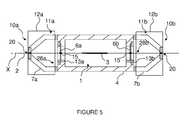
- FIG. 5shows a longitudinal cross-section of the hydrophone with hydrostatic filters.
- FIG. 1shows the detail of a Bragg grating fibre hydrophone, according to a possible embodiment of the invention.
- the Bragg grating fibre hydrophonecomprises an optical fibre 2 and a fluid cavity 1 filled with a compressible fluid.
- the fluid cavity 1is delimited by a rigid casing 4 comprising two end faces 28 a , 28 b , integral with the optical fibre 2 , and opposite to each other.
- At least one of the two end faces 28 a , 28 b of the rigid casing 4comprises an opening 5 a , 5 b closed by a deformable diaphragm 6 a , 6 b integral with the optical fibre 2 .
- the two end faces 28 a , 28 b of the rigid casing 4are formed by an opening 5 a , 5 b closed by a deformable diaphragm 6 a , 6 b integral with the optical fibre 2 .
- a Bragg grating 3is integrated in the optical fibre 2 , forming a laser cavity.
- the Bragg grating 3may be photo-inscribed in the optical fibre 2 .
- the optical fibre 2extends through the fluid cavity 1 along a longitudinal axis (X) in such a manner that the Bragg grating 3 is positioned inside the latter.
- the optical fibre 2has a sensitivity comprised between 3 and 4.5 nm/MPa, a diameter of 125 ⁇ m, and a Young modulus comprised between 50 GPa and 90 GPa, preferably equal to 70 GPa.
- the two openings 5 a , 5 bare opposite to each other, and separated from each other by the Bragg grating 3 .
- the deformable diaphragms 6 a , 6 bare passed through by the optical fibre 2 , and are integral with the latter.
- the deformable diaphragms 6 a , 6 bmay be fastened to the optical fibre 2 by welding or bonding, for example.
- the weldingmay be a laser welding with or without a ferule.
- the bondingmay be a polyamide coating or epoxy adhesive bonding.
- the deformable diaphragms 6 a , 6 bare capable of being deformed by a difference in the pressures applied to its faces, causing a length variation of the optical fibre 2 measured by a variation of wavelength of a luminous flux extracted from the optical fibre 2 . More precisely, this is the length variation of the laser cavity that is measured.
- ⁇ Pis the pressure applied to the structure
- S optis the sensitivity of the “bare” Bragg grating
- G mecais the desired mechanical gain
- the optical pumping of the optical fibre 2may be performed by a laser diode at 980 nm, for example.
- the luminous flux extracted from the optical fibre 2has a wavelength that is a function of the lengthening or the shortening of the optical fibre 2 .
- the wavelength variationsare measured by a Mach Zehnder interferometer, for example.
- the deformable diaphragms 6 a , 6 bare deformed and curved toward the inside of the fluid cavity 1 , causing a shortening of the optical fibre 2 or laser cavity.
- the external pressure P eis applied to the outer face 29 of the deformable diaphragms 6 a , 6 b , while the internal pressure P i is applied to the inner face 30 of the deformable diaphragms 6 a , 6 b.
- the length of the hydrophoneis shorter than the acoustic wavelengths measured.
- the pressure fieldis supposed to be homogeneous.
- the deformable diaphragms 6 a , 6 bmay be made of metal or polymer, for example. They may be made of bronze or brass.
- the deformable diaphragms 6 a , 6 b and the rigid casing 4delimit the fluid cavity 1 and form a tight unit.
- the rigid casing 4has a tubular shape.
- the rigid casing 4has the highest possible Young modulus, higher than 100 GPa.
- the rigid casing 4has to be the less deformable possible.
- the rigid casing 4may be made of titanium, for example, with a Young modulus of 120 GPa.
- the openings 5 a , 5 b of the rigid casing 4 and the deformable diaphragms 6 a , 6 bhave a circular shape.
- the compressible fluid of the fluid cavity 1has a compressibility modulus lower than 1.5 Gpa.
- the compressible fluidmay be based on fluorocarbon, as for example perfluorohexane (C 6 F 14 ), which has a compressibility modulus of 1 GPa.
- fluorocarbonas for example perfluorohexane (C 6 F 14 ), which has a compressibility modulus of 1 GPa.
- the fluid usedis inert fluorine provided by the 3M company.
- the deformable diaphragms 6 a , 6 bare integral with an annular part 21 so as to form a sleeve.
- This sleeveis inserted into one of the openings 5 a , 5 b of the rigid casing 4 , so as to tightly close it up.
- An O-ring 17may be provided between the annular part 21 and the wall of the rigid casing 4 delimiting one of the openings 5 a , 5 b , to ensure the tightness.
- a locking nut 16locks the sleeve longitudinally against a part of the rigid casing 4 forming a stop.
- the optical fibre 2is threaded into the latter, so as to go through the rigid casing 4 along the main axis (X).
- the main axis (X)is a longitudinal central axis.
- the optical fibre 2passes through the centre of the deformable diaphragms 6 a , 6 b.
- the principle of operation of the Bragg grating or laser fibre hydrophoneis based on the lengthening of a laser cavity (Bragg grating 3 ).
- the geometry of the Bragg grating 3 and the index of the mediumdetermine the resonance frequency of the laser cavity, and thus the wavelength thereof.
- the radial pressure applied to the laser cavitymodifies the geometry thereof and induces stresses in the silica of the fibre.
- the lengthening and the stress level in the laser cavitymodify the geometry and the medium's index, respectively. These modifications induce a variation of the resonance frequency, thus of the laser wavelength.
- the optical fibre hydrophoneuses this property for detecting the acoustic waves.
- the deformable diaphragms 6 a , 6 b , the compressible fluid and the rigid casing 4form a mechanical amplifier for increasing this sensitivity to the external pressure P e .
- Such amplifierpermits to amplify the axial deformations, while the radial deformations remain very low.
- a low-frequency acoustic wavecauses a local variation of the pressure around the hydrophone.
- the external pressure (P e )thus becomes different from the pressure (P i ) within the fluid cavity 1 .
- the fluid cavity 1via its compressibility, tends to balance its pressure with the external pressure by a variation of its volume:
- ⁇ sis the adiabatic compressibility of the fluid
- Vis the volume of the fluid cavity 1
- dVis the variation of volume of the cavity.
- the hydrophone geometryforces the optical fibre 2 to deform axially.
- S axis the effective surface of the diaphragm 6 a , 6 b
- Ris the inner radius of the rigid casing 4
- Iis the length of the rigid casing 4 .
- k ax and k radare the axial and radial stiffness of the system, respectively
- S ris the inner radial surface of the rigid casing 4
- Pis the incident pressure
- k radmainly depends on the type of material of the rigid casing 4 .
- k axdepends both on the properties and size of the diaphragm 6 a , 6 b , and on the stiffness of the fluid cavity 1 .
- Such a systemdirects the deformations in the axial direction by: k ax ⁇ k rad .
- Vis the volume of the fluid cavity 1
- Sis the section of the diaphragm 6 a , 6 b.
- the gainmay also be expressed as the ratio between the axial deformation of the optical fibre due to the mechanical amplifier and the axial deformation of this fibre due to the pressure to the latter, in bare state.
- the rigid casing 4may have a length of 250 mm, with an inner diameter of 30 mm and an outer diameter of 35 mm.
- the distance between the two deformable diaphragms 6 a , 6 bmay be of 70 mm, their thickness of 0.1 mm, and their diameter of 22 mm.
- the optical fibremay have a diameter of 125 ⁇ m, and the Bragg grating 3 may extend over a length of 50 mm.
- the compressibility modulus of the compressible fluidmay be of 1 Gpa. These parameters make it possible to reach a gain of 1700.
- the two deformable diaphragms 6 a , 6 bhave the lowest Young modulus possible, lower than 100 Gpa.
- the hydrophone according to the inventionmakes it possible to reach gains higher than 1 000.
- the optical fibre 2is a pre-stressed optical fibre. As illustrated in FIGS. 2 and 4 , the tension of the optical fibre 2 is held by holding means 7 a , 7 b , arranged on either side of the fluid cavity 1 , and fastened to each of the end faces 28 a , 28 b of the rigid casing 4 .
- Each holding means 7 a , 7 bare arranged in front of each of the openings 5 a , 5 b of the rigid casing 4 , and outside the fluid cavity 1 .
- Each holding means 7 a , 7 bhas a first end 8 integral with the rigid casing 4 and a second end 9 which is passed through by the optical fibre 2 and integral with the latter.
- the holding means 7 a , 7 blean on the end sides of the rigid casing 4 .
- Theycomprise three tabs 18 having each a first end fastened to one end side of the rigid casing 4 and a second end fastened to a three-leg support 19 , ended by a holding ring provided with an orifice 20 at the centre thereof.
- This orifice 20is provided for the optical fibre 2 to pass through and to be fastened.
- the optical fibre 2is threaded into the orifice 15 provided in the deformable diaphragm 6 a , 6 b , so that the Bragg grating 3 is located at the centre of the fluid cavity 1 .
- optical fibre 2is then fastened to the second end 9 of one of the holding means 7 a , 7 b , by welding or bonding.
- a calibrated pre-stressis applied on the other side, by pulling the optical fibre 2 .
- optical fibre 2being tensioned, it is welded or bonded to the second end 9 of another holding means 7 a , 7 b.
- the optical fibre 2is fastened to the two deformable diaphragms 6 a , 6 b by laser bonding or welding.
- optical fibre 2is then cut and butt jointed on either side with a cladded optical fibre.
- the holding means 7 a , 7 bmake it possible to avoid the optical fibre 2 to fold over itself during a strong acoustic pressure.
- the pre-stress applied to the optical fibre 2is calculated to be higher than the maximum deformations the device will be capable of tolerating. Therefore, the optical fibre 2 will always be tensioned during the hydrophone operation.
- the maximum pre-stress that can be applied to the fibreis 2N, which corresponds to a maximum stress of
- the Young modulus of the optical fibre 2being of 70 GPa, the maximum expansion operating deformation of the optical fibre 2 is thus:
- the Bragg grating fibre hydrophonecomprises at least one hydrostatic filter 10 a , 10 b , associated with one deformable diaphragm 6 a , 6 b of the rigid casing 4 , respectively.
- Each hydrostatic filter 10 a , 10 bhas a tank 11 a , 11 b delimited by a deformable outer casing 12 a , 12 b and by one of the deformable diaphragms 6 a , 6 b of the mechanical amplifier.
- the tank 11 a , 11 bis in fluid communication with the fluid cavity 1 by means of an orifice 13 a , 13 b extending through each deformable diaphragm 6 a , 6 b .
- the deformable casing 12 a , 12 bis tightly fastened to the rigid casing 4 , and covers the holding means 7 a , 7 b associated with the deformable diaphragm 6 a , 6 b.
- the Bragg grating fibre hydrophonecomprises two hydrostatic filters 10 a , 10 b , arranged on either side of the rigid casing 4 .
- the deformable outer casing 12 a , 12 b of the hydrostatic filter 10 a , 10 bhas a cap shape and may be made of polymer, for example.
- the tanks 11 a , 11 b and the fluid cavity 1are filled with the same compressible fluid.
- Each deformable outer casing 12 a , 12 btransmits the pressure variations to one deformable diaphragm 6 a , 6 b , respectively, by means of the compressible fluid.
- the orifices 13 a , 13 b of the hydrostatic filters 10 a , 10 bhave a diameter comprised between 100 ⁇ m and 20 ⁇ m, preferably equal to 50 ⁇ m.
- the hydrostatic filters 10 a , 10 bmake it possible to place the inner fluid at the hydrostatic pressure after a slow pressure variation following a change of temperature or immersion. Therefore, it is possible to free from the hydrostatic pressure and to take into account only the pressure variations around this pressure. It is to be noted that these hydrostatic filters represent a limitation for the detection of very low frequencies. Indeed, the time of reaction of the hydrostatic filter will determine the lowest frequency that can be measured by the hydrophone.
- the hydrostatic filtersare high-pass filters. Therefore, if the frequency of the acoustic wave is lower than the cut-off frequency of the hydrostatic filter, it will be without effect on this acoustic wave.
- the very low frequenciesare filtered out by this method.
- the hole size of the hydrostatic filtersdetermines the low cut-off frequency, and thus the low limit of the working band of the hydrophone.
- the cut-off frequencyis lower than 10 Hz, preferably equal to 0.4 Hz.
- the hydrophonemakes it possible to detect acoustic waves in the frequency band comprised between 0.4 Hz and 10 kHz.
- the section of the deformable diaphragms 6 a , 6 bis smaller than that of the deformable casing 12 a , 12 b of the hydrostatic filters 10 a , 10 b.
- the diameter of the deformable diaphragms 6 a , 6 bis lower than the inner diameter of the rigid casing 4 , taken apart from the ends of the rigid casing 4 .
- the orifices 13 a , 13 b of the hydrostatic filters 10 a , 10 bmake it possible to perform a pressure balance between the inside of the rigid casing 4 and the inside of the tanks 11 a , 11 b of the hydrostatic filters 10 a , 10 b , and a temperature compensation, making the hydrophone insensitive to the slow variations of pressure and temperature during immersions of the hydrophone at variable depths.
- the hydrostatic filters 10 a , 10 bmake it possible to attenuate the effects of waves and swell.
- the deformable outer casings 12 a , 12 b of the hydrostatic filter 10 a , 10 bare tightly fastened to the rigid casing 4 by clamping rings (not shown).
- the Bragg grating fibre hydrophonecomprises support frameworks fastened to either side of the rigid casing 4 , at the ends thereof (not shown). These support frameworks have a tubular shape and comprise three side openings.
- These support frameworkscomprise one end linked to one the ends of the rigid casing 4 and another end closed by a plug, provided with a central orifice forming a passageway for the optical fibre(s) 2 (not shown).
- This plugmay be made of Ertalyte, for example.
- Groovesmay be provided in the outer surface of the rigid casing 4 to accommodate external optical fibres that may be connected to other acoustic pressure sensors, for example.
- An elastomeric cap(not shown) may be provided at the output of the central orifice of the plug, to protect the optical fibre(s).
- the Bragg grating fibre hydrophonemay comprise a flexible and tight outer casing (not shown), surrounding the unit formed by the rigid casing 4 , the hydrostatic filters 10 a , 10 b , and the support frameworks.
- the outer casingis cylindrical and filled with a fluid so as to transmit the pressure variations external to said fluid cavity 1 .
- This fluidmay be castor oil, for example.
- the outer casingmay be made of polymer, for example Hypalon®.
- the inventionprovides a hydrophone that makes it possible to reach high gains, higher than 1 000, and thus acoustic sensitivities higher than those reached by the known hydrophones.
- the hydrophoneis insensitive to the accelerometer noise when it is towed by a ship or a submarine.
Landscapes
- Physics & Mathematics (AREA)
- Engineering & Computer Science (AREA)
- Remote Sensing (AREA)
- Life Sciences & Earth Sciences (AREA)
- General Physics & Mathematics (AREA)
- Acoustics & Sound (AREA)
- Environmental & Geological Engineering (AREA)
- Geology (AREA)
- General Life Sciences & Earth Sciences (AREA)
- Geophysics (AREA)
- Measurement Of Mechanical Vibrations Or Ultrasonic Waves (AREA)
Abstract
Description
- said fluid cavity is filled with a compressible fluid and is delimited by a rigid casing comprising two end faces integral with the optical fibre,
- at least one of the two end faces of the rigid casing comprises an opening closed by a deformable diaphragm integral with said optical fibre, wherein said deformable diaphragm is capable of being deformed by a difference in the pressures applied to its faces, causing a length variation of the optical fibre measured by a variation of wavelength of a luminous flux extracted from the optical fibre.
- the two end faces of the rigid casing each comprise an opening closed by a deformable diaphragm integral with said optical fibre,
- said optical fibre is a pre-stressed optical fibre, wherein the tension of said optical fibre is held by holding means, with said holding means leaning on each of the end faces of the rigid casing, respectively,
- the holding means are arranged outside the fluid cavity, wherein each holding means has a first end integral with the rigid casing and a second end which is passed through by the optical fibre and integral with the latter,
- the Bragg grating fibre hydrophone comprises at least one hydrostatic filter cooperating with the fluid cavity, wherein each hydrostatic filter is provided with an orifice capable of providing a fluid communication between the inside and the outside of the fluid cavity,
- each hydrostatic filter is associated with one of the deformable diaphragms, wherein each hydrostatic filter includes a tank delimited by a deformable outer casing and by one of the end faces of the rigid casing, said tank being in fluid communication with the fluid cavity, through said orifice extending through the deformable diaphragm, said deformable outer casing being tightly fastened to the rigid casing.
- the section of the deformable diaphragms is smaller than that of the deformable casing of the hydrostatic filters,
- the elements forming said hydrophone have a resonance frequency outside the frequency range comprised between 0.4 Hz and 10 kHz.
- the Bragg grating fibre hydrophone comprises a flexible and tight outer casing, surrounding the unit formed by the rigid casing and the hydrostatic filters, wherein said outer casing is filled with a fluid so as to transmit the pressure variations external to said fluid cavity,
- the compressible fluid of the fluid cavity has a compressibility modulus lower than 1.5 Gpa, preferably lower than 0.5 GPa.
Δλ=SoptGmecaΔP
where εxis the axial lengthening of the optical fibre (laser cavity) and Peis the external pressure. In the case of the fibre alone, the theoretical sensitivity is
where E and ν are the Young modulus and the Poisson ratio of the silica, respectively.
dV=dx*Sax+(πR2−π(R+dr)?I
for an
The maximum operating acoustic pressure of the hydrophone is thus:
Claims (13)
Applications Claiming Priority (3)
| Application Number | Priority Date | Filing Date | Title |
|---|---|---|---|
| FR0953575AFR2946140B1 (en) | 2009-05-29 | 2009-05-29 | BRAGG NETWORK FIBER HYDROPHONE WITH MEMBRANE AMPLIFIER |
| FR0953575 | 2009-05-29 | ||
| PCT/FR2010/051016WO2010136723A1 (en) | 2009-05-29 | 2010-05-27 | Fiber bragg grating hydrophone comprising a diaphragm amplifier |
Publications (2)
| Publication Number | Publication Date |
|---|---|
| US20120093463A1 US20120093463A1 (en) | 2012-04-19 |
| US8687927B2true US8687927B2 (en) | 2014-04-01 |
Family
ID=41491455
Family Applications (1)
| Application Number | Title | Priority Date | Filing Date |
|---|---|---|---|
| US13/375,037Active2030-10-03US8687927B2 (en) | 2009-05-29 | 2010-05-27 | Fiber bragg grating hydrophone comprising a diaphragm amplifier |
Country Status (5)
| Country | Link |
|---|---|
| US (1) | US8687927B2 (en) |
| EP (1) | EP2435855B1 (en) |
| JP (1) | JP5717728B2 (en) |
| FR (1) | FR2946140B1 (en) |
| WO (1) | WO2010136723A1 (en) |
Cited By (5)
| Publication number | Priority date | Publication date | Assignee | Title |
|---|---|---|---|---|
| US20190331942A1 (en)* | 2016-07-13 | 2019-10-31 | Technology Innovation Momentum Fund (Israel) Limited Partnership | Coupling sensor information to an optical cable using ultrasonic vibrations |
| US20190360323A1 (en)* | 2018-05-24 | 2019-11-28 | Baker Hughes, A Ge Company, Llc | Transducers including laser etched substrates |
| EP3516166A4 (en)* | 2016-09-23 | 2020-06-10 | Baker Hughes, a GE company, LLC | Downhole fiber optic hydrophone |
| US11867855B2 (en) | 2019-12-10 | 2024-01-09 | Baker Hughes Oilfield Operations Llc | Downhole fiber optic hydrophone |
| US12044557B2 (en) | 2019-07-02 | 2024-07-23 | Ramot At Tel Aviv University Ltd. | Interrogation of arrays of equally spaced weak reflectors in optical fibers |
Families Citing this family (29)
| Publication number | Priority date | Publication date | Assignee | Title |
|---|---|---|---|---|
| FR2946141B1 (en)* | 2009-05-29 | 2011-09-30 | Ixsea | BRAGG NETWORK FIBER HYDROPHONE WITH BELLOW AMPLIFIER |
| US8820167B2 (en) | 2011-02-10 | 2014-09-02 | Siemens Energy, Inc. | Vibration sensor |
| GB201103254D0 (en)* | 2011-02-25 | 2011-04-13 | Qinetiq Ltd | Distributed acoustic sensing |
| FR2974263B1 (en)* | 2011-04-14 | 2014-10-24 | Thales Sa | ANY OPTICAL HYDROPHONE THAT IS INSENSITIVE AT TEMPERATURE AND STATIC PRESSURE |
| WO2013098321A2 (en) | 2011-12-30 | 2013-07-04 | Shell Internationale Research Maatschappij B.V. | Smart hydrocarbon fluid production method and system |
| CN103438979A (en)* | 2013-08-14 | 2013-12-11 | 武汉普惠海洋光电技术有限公司 | Fixing device for optical fiber hydrophone |
| CN104570145B (en)* | 2015-02-14 | 2017-03-22 | 吉林大学 | Optical fiber sensing life detection equipment |
| FR3034207B1 (en) | 2015-03-27 | 2018-01-19 | Thales | FIBER OPTIC SENSOR DEVICE |
| FR3037146B1 (en)* | 2015-06-08 | 2018-07-20 | Airbus (S.A.S.) | PRESSURE MEASURING DEVICE |
| CN105352652B (en)* | 2015-09-30 | 2017-12-15 | 南京航空航天大学 | Differential optical fiber grating baroceptor and the method for monitoring aircraft airspeed pipe dynamic pressure |
| WO2017079496A1 (en)* | 2015-11-04 | 2017-05-11 | Quantum Technolgy Sciences, Inc. (Qtsi) | Acoustic and seismic sensor device provding improved sensitivity |
| CN106289502B (en)* | 2016-08-11 | 2019-01-22 | 中国船舶重工集团公司第七一五研究所 | A kind of trivector hydrophone and phase demodulating method based on distributed feedback optical fiber laser |
| US11396502B2 (en) | 2018-11-13 | 2022-07-26 | Incyte Corporation | Substituted heterocyclic derivatives as PI3K inhibitors |
| US11078204B2 (en) | 2018-11-13 | 2021-08-03 | Incyte Corporation | Heterocyclic derivatives as PI3K inhibitors |
| US11161838B2 (en) | 2018-11-13 | 2021-11-02 | Incyte Corporation | Heterocyclic derivatives as PI3K inhibitors |
| CN111307362B (en)* | 2020-03-25 | 2021-06-15 | 电子科技大学 | Fiber bragg grating pressure sensor and using method thereof |
| CN111399034B (en)* | 2020-03-31 | 2021-03-16 | 武汉理工大学 | Hydrophone detection device and method based on low bending loss chirped grating array |
| CN111337117B (en)* | 2020-04-14 | 2022-07-05 | 青岛海洋科学与技术国家实验室发展中心 | Optical fiber laser hydrophone |
| CN112629641B (en)* | 2020-11-30 | 2023-03-28 | 中山市精量光电子科技有限公司 | Flywheel-shaped diaphragm type high-sensitivity standard hydrophone and method |
| CN112924013B (en)* | 2021-01-28 | 2022-04-05 | 哈尔滨工程大学 | Acceleration-resistant optical fiber hydrophone probe device |
| CN113405645B (en)* | 2021-06-08 | 2022-09-27 | 哈尔滨工程大学 | A Piston-Based Hydrostatic Pressure Resistant Fiber Optic Hydrophone |
| CN114623916A (en)* | 2022-02-28 | 2022-06-14 | 浙江大学 | A Fiber Bragg Grating Hydrophone Using Double Conical Truncated Diaphragm |
| CN114623915A (en)* | 2022-02-28 | 2022-06-14 | 浙江大学 | A Double Diaphragm Fiber Bragg Grating Hydrophone Using Tensile Coating Sensitization |
| CN114623914A (en)* | 2022-02-28 | 2022-06-14 | 浙江大学 | A fiber grating hydrophone with frustum diaphragm and tensile coating |
| CN114623913A (en)* | 2022-02-28 | 2022-06-14 | 浙江大学 | Fiber grating hydrophone adopting cymbal-shaped diaphragm and tensile coating |
| CN114623917A (en)* | 2022-02-28 | 2022-06-14 | 浙江大学 | Low-pass filtering fiber grating hydrophone adopting frustum-shaped diaphragm |
| CN114593811A (en)* | 2022-02-28 | 2022-06-07 | 浙江大学 | A low-pass filter fiber grating hydrophone with cymbal-shaped diaphragm |
| CN115096426B (en)* | 2022-05-31 | 2025-08-22 | 南京隆沃科技有限公司 | Perimeter warning monitoring device and method using fiber grating |
| FR3154800A1 (en) | 2023-10-25 | 2025-05-02 | Airbus Helicopters | Measuring system comprising an optical fiber equipped with at least one Bragg grating for measuring dynamic deformation, aircraft and process. |
Citations (13)
| Publication number | Priority date | Publication date | Assignee | Title |
|---|---|---|---|---|
| US3660809A (en)* | 1970-06-29 | 1972-05-02 | Whitehall Electronics Corp | Pressure sensitive hydrophone |
| GB2145237A (en) | 1981-04-03 | 1985-03-20 | Chevron Res | Optical system |
| US4545253A (en)* | 1983-08-29 | 1985-10-08 | Exxon Production Research Co. | Fiber optical modulator and data multiplexer |
| US5311485A (en)* | 1992-10-30 | 1994-05-10 | The United States Of America As Represented By The United States Department Of Energy | Fiber optic hydrophone |
| US5363342A (en)* | 1988-04-28 | 1994-11-08 | Litton Systems, Inc. | High performance extended fiber optic hydrophone |
| US6160763A (en)* | 1998-12-28 | 2000-12-12 | Sealandaire Technologies, Inc. | Towed array hydrophone |
| US6160762A (en) | 1998-06-17 | 2000-12-12 | Geosensor Corporation | Optical sensor |
| US6175108B1 (en) | 1998-01-30 | 2001-01-16 | Cidra Corporation | Accelerometer featuring fiber optic bragg grating sensor for providing multiplexed multi-axis acceleration sensing |
| US20020154860A1 (en)* | 1998-12-04 | 2002-10-24 | Fernald Mark R. | Bragg grating pressure sensor for industrial sensing applications |
| EP1310801A1 (en) | 2001-11-13 | 2003-05-14 | Abb Research Ltd. | Seismic fiber laser sensor |
| US20040202401A1 (en)* | 2002-10-06 | 2004-10-14 | Arne Berg | High pressure and high temperature acoustic sensor |
| US20040237648A1 (en) | 2003-06-02 | 2004-12-02 | Jones Richard Todd | Optical accelerometer or displacement device using a flexure system |
| US20120082415A1 (en)* | 2009-05-29 | 2012-04-05 | Ixblue | Bragg grating fiber hydrophone with a bellows amplifier |
Family Cites Families (3)
| Publication number | Priority date | Publication date | Assignee | Title |
|---|---|---|---|---|
| JP4615726B2 (en)* | 1998-12-04 | 2011-01-19 | ウェザーフォード/ラム インコーポレーテッド | Bragg grating pressure sensor |
| CA2581866C (en) | 2004-09-28 | 2014-12-23 | The Commonwealth Of Australia | Acoustic pressure sensor |
| CN100507475C (en) | 2006-12-31 | 2009-07-01 | 中国科学院半导体研究所 | A static pressure self-compensating fiber grating hydrophone |
- 2009
- 2009-05-29FRFR0953575Apatent/FR2946140B1/enactiveActive
- 2010
- 2010-05-27EPEP10728825.0Apatent/EP2435855B1/ennot_activeRevoked
- 2010-05-27WOPCT/FR2010/051016patent/WO2010136723A1/enactiveApplication Filing
- 2010-05-27JPJP2012512434Apatent/JP5717728B2/enactiveActive
- 2010-05-27USUS13/375,037patent/US8687927B2/enactiveActive
Patent Citations (14)
| Publication number | Priority date | Publication date | Assignee | Title |
|---|---|---|---|---|
| US3660809A (en)* | 1970-06-29 | 1972-05-02 | Whitehall Electronics Corp | Pressure sensitive hydrophone |
| GB2145237A (en) | 1981-04-03 | 1985-03-20 | Chevron Res | Optical system |
| US4545253A (en)* | 1983-08-29 | 1985-10-08 | Exxon Production Research Co. | Fiber optical modulator and data multiplexer |
| FR2562741A1 (en) | 1984-04-05 | 1985-10-11 | Exxon Production Research Co | FIBER OPTIC DATA COLLECTION SYSTEM |
| US5363342A (en)* | 1988-04-28 | 1994-11-08 | Litton Systems, Inc. | High performance extended fiber optic hydrophone |
| US5311485A (en)* | 1992-10-30 | 1994-05-10 | The United States Of America As Represented By The United States Department Of Energy | Fiber optic hydrophone |
| US6175108B1 (en) | 1998-01-30 | 2001-01-16 | Cidra Corporation | Accelerometer featuring fiber optic bragg grating sensor for providing multiplexed multi-axis acceleration sensing |
| US6160762A (en) | 1998-06-17 | 2000-12-12 | Geosensor Corporation | Optical sensor |
| US20020154860A1 (en)* | 1998-12-04 | 2002-10-24 | Fernald Mark R. | Bragg grating pressure sensor for industrial sensing applications |
| US6160763A (en)* | 1998-12-28 | 2000-12-12 | Sealandaire Technologies, Inc. | Towed array hydrophone |
| EP1310801A1 (en) | 2001-11-13 | 2003-05-14 | Abb Research Ltd. | Seismic fiber laser sensor |
| US20040202401A1 (en)* | 2002-10-06 | 2004-10-14 | Arne Berg | High pressure and high temperature acoustic sensor |
| US20040237648A1 (en) | 2003-06-02 | 2004-12-02 | Jones Richard Todd | Optical accelerometer or displacement device using a flexure system |
| US20120082415A1 (en)* | 2009-05-29 | 2012-04-05 | Ixblue | Bragg grating fiber hydrophone with a bellows amplifier |
Non-Patent Citations (1)
| Title |
|---|
| International search report dated Sep. 21, 2010 in corresponding PCT/FR2010/051016. |
Cited By (8)
| Publication number | Priority date | Publication date | Assignee | Title |
|---|---|---|---|---|
| US20190331942A1 (en)* | 2016-07-13 | 2019-10-31 | Technology Innovation Momentum Fund (Israel) Limited Partnership | Coupling sensor information to an optical cable using ultrasonic vibrations |
| EP3485325A4 (en)* | 2016-07-13 | 2020-02-26 | Technology Innovation Momentum Fund (Israel) Limited Partnership | COUPLING SENSOR INFORMATION TO AN OPTICAL CABLE BY MEANS OF ULTRASOUND VIBRATIONS |
| US10598969B2 (en)* | 2016-07-13 | 2020-03-24 | Technology Innovation Momentum Fund (Israel) Limited Partnership | Coupling sensor information to an optical cable using ultrasonic vibrations |
| US11187925B2 (en)* | 2016-07-13 | 2021-11-30 | Technology Innovation Momentum Fund (Israel) Limited Partnership | Coupling sensor information to an optical cable using ultrasonic vibrations |
| EP3516166A4 (en)* | 2016-09-23 | 2020-06-10 | Baker Hughes, a GE company, LLC | Downhole fiber optic hydrophone |
| US20190360323A1 (en)* | 2018-05-24 | 2019-11-28 | Baker Hughes, A Ge Company, Llc | Transducers including laser etched substrates |
| US12044557B2 (en) | 2019-07-02 | 2024-07-23 | Ramot At Tel Aviv University Ltd. | Interrogation of arrays of equally spaced weak reflectors in optical fibers |
| US11867855B2 (en) | 2019-12-10 | 2024-01-09 | Baker Hughes Oilfield Operations Llc | Downhole fiber optic hydrophone |
Also Published As
| Publication number | Publication date |
|---|---|
| FR2946140B1 (en) | 2011-12-09 |
| EP2435855B1 (en) | 2015-12-02 |
| EP2435855A1 (en) | 2012-04-04 |
| JP2012528314A (en) | 2012-11-12 |
| FR2946140A1 (en) | 2010-12-03 |
| JP5717728B2 (en) | 2015-05-13 |
| US20120093463A1 (en) | 2012-04-19 |
| WO2010136723A1 (en) | 2010-12-02 |
Similar Documents
| Publication | Publication Date | Title |
|---|---|---|
| US8687927B2 (en) | Fiber bragg grating hydrophone comprising a diaphragm amplifier | |
| US8676008B2 (en) | Bragg grating fiber hydrophone with a bellows amplifier including a fluid cavity and an optical fibre in which the bragg grating is integrated | |
| KR102112366B1 (en) | All-optical hydrophone that is not sensitive to temperature or static pressure | |
| AU754039B2 (en) | Non-intrusive fiber optic pressure sensor for measuring unsteady pressures within a pipe | |
| US6549488B2 (en) | Fiber-optic hydrophone | |
| EP3071941B1 (en) | Sensor for detecting pressure waves in a fluid, provided with static pressure compensation | |
| US7551517B2 (en) | Seabed seismic station packaging | |
| US6450037B1 (en) | Non-intrusive fiber optic pressure sensor for measuring unsteady pressures within a pipe | |
| EP3137867B1 (en) | Optical fiber sensor assembly | |
| US7295493B1 (en) | Pressure tolerant fiber optic hydrophone | |
| US7466631B1 (en) | Enhanced sensitivity pressure tolerant fiber optic hydrophone | |
| JP2016528502A (en) | Sensor for detecting pressure waves in liquid | |
| AU2016239915B2 (en) | Optical-fibre sensor device | |
| AU2017317614B2 (en) | Hydrophone with optimised optical fibre | |
| Ames | Pressure Tolerant Fiber Optic Hydrophone |
Legal Events
| Date | Code | Title | Description |
|---|---|---|---|
| AS | Assignment | Owner name:IXSEA, FRANCE Free format text:ASSIGNMENT OF ASSIGNORS INTEREST;ASSIGNORS:GROSSO, GILLES;MOSCA, FREDERIC;REEL/FRAME:027557/0643 Effective date:20100729 | |
| AS | Assignment | Owner name:IXBLUE, FRANCE Free format text:CHANGE OF NAME;ASSIGNOR:IXSEA;REEL/FRAME:032174/0106 Effective date:20101102 | |
| STCF | Information on status: patent grant | Free format text:PATENTED CASE | |
| AS | Assignment | Owner name:IXBLUE, FRANCE Free format text:CHANGE OF ADDRESS;ASSIGNOR:IXBLUE;REEL/FRAME:037515/0691 Effective date:20151001 | |
| MAFP | Maintenance fee payment | Free format text:PAYMENT OF MAINTENANCE FEE, 4TH YEAR, LARGE ENTITY (ORIGINAL EVENT CODE: M1551) Year of fee payment:4 | |
| MAFP | Maintenance fee payment | Free format text:PAYMENT OF MAINTENANCE FEE, 8TH YEAR, LARGE ENTITY (ORIGINAL EVENT CODE: M1552); ENTITY STATUS OF PATENT OWNER: LARGE ENTITY Year of fee payment:8 | |
| AS | Assignment | Owner name:EXAIL, FRANCE Free format text:CHANGE OF NAME AND ADDRESS;ASSIGNOR:IXBLUE;REEL/FRAME:063237/0952 Effective date:20230101 | |
| MAFP | Maintenance fee payment | Free format text:PAYMENT OF MAINTENANCE FEE, 12TH YEAR, LARGE ENTITY (ORIGINAL EVENT CODE: M1553); ENTITY STATUS OF PATENT OWNER: LARGE ENTITY Year of fee payment:12 |