US8687717B2 - Method and apparatus for closed loop beamforming in wireless communication systems - Google Patents
Method and apparatus for closed loop beamforming in wireless communication systemsDownload PDFInfo
- Publication number
- US8687717B2 US8687717B2US12/500,154US50015409AUS8687717B2US 8687717 B2US8687717 B2US 8687717B2US 50015409 AUS50015409 AUS 50015409AUS 8687717 B2US8687717 B2US 8687717B2
- Authority
- US
- United States
- Prior art keywords
- communication channel
- beamforming
- condition
- beamformed
- receiver
- Prior art date
- Legal status (The legal status is an assumption and is not a legal conclusion. Google has not performed a legal analysis and makes no representation as to the accuracy of the status listed.)
- Active, expires
Links
Images


Classifications
- H—ELECTRICITY
- H04—ELECTRIC COMMUNICATION TECHNIQUE
- H04B—TRANSMISSION
- H04B7/00—Radio transmission systems, i.e. using radiation field
- H04B7/02—Diversity systems; Multi-antenna system, i.e. transmission or reception using multiple antennas
- H04B7/04—Diversity systems; Multi-antenna system, i.e. transmission or reception using multiple antennas using two or more spaced independent antennas
- H04B7/06—Diversity systems; Multi-antenna system, i.e. transmission or reception using multiple antennas using two or more spaced independent antennas at the transmitting station
- H04B7/0613—Diversity systems; Multi-antenna system, i.e. transmission or reception using multiple antennas using two or more spaced independent antennas at the transmitting station using simultaneous transmission
- H04B7/0615—Diversity systems; Multi-antenna system, i.e. transmission or reception using multiple antennas using two or more spaced independent antennas at the transmitting station using simultaneous transmission of weighted versions of same signal
- H04B7/0617—Diversity systems; Multi-antenna system, i.e. transmission or reception using multiple antennas using two or more spaced independent antennas at the transmitting station using simultaneous transmission of weighted versions of same signal for beam forming
- H—ELECTRICITY
- H04—ELECTRIC COMMUNICATION TECHNIQUE
- H04B—TRANSMISSION
- H04B7/00—Radio transmission systems, i.e. using radiation field
- H04B7/02—Diversity systems; Multi-antenna system, i.e. transmission or reception using multiple antennas
- H04B7/04—Diversity systems; Multi-antenna system, i.e. transmission or reception using multiple antennas using two or more spaced independent antennas
- H04B7/06—Diversity systems; Multi-antenna system, i.e. transmission or reception using multiple antennas using two or more spaced independent antennas at the transmitting station
- H04B7/0613—Diversity systems; Multi-antenna system, i.e. transmission or reception using multiple antennas using two or more spaced independent antennas at the transmitting station using simultaneous transmission
- H04B7/0615—Diversity systems; Multi-antenna system, i.e. transmission or reception using multiple antennas using two or more spaced independent antennas at the transmitting station using simultaneous transmission of weighted versions of same signal
- H04B7/0619—Diversity systems; Multi-antenna system, i.e. transmission or reception using multiple antennas using two or more spaced independent antennas at the transmitting station using simultaneous transmission of weighted versions of same signal using feedback from receiving side
- H04B7/0621—Feedback content
- H04B7/0632—Channel quality parameters, e.g. channel quality indicator [CQI]
Definitions
- the present inventionrelates generally to wireless communication systems and more specifically to closed loop beamforming for wireless communication systems.
- Beamformingis a method for using wireless channel information to transmit signals to the receiver in order to improve reception quality, and increase data throughput in a Multi-In, Multi-Out (MIMO) communication system.
- MIMOMulti-In, Multi-Out
- the remaining issue for closed loop beamformingis system stability.
- the beamforming parametersare very straightforward to compute for a given channel condition.
- the wireless channel between the transmitter and receiveris constantly changing, due to changes in the environment, which cause fluctuation in the Signal-to-Noise Ration (SNR) and varying multipath conditions. Therefore, a certain set of beamforming parameters may not apply to the current channel, and be considered “stale”. If a closed loop system does not anticipate the changing channel conditions, and does not qualify beamforming sets, the throughput can degrade, and the link can become unstable.
- SNRSignal-to-Noise Ration
- Varying embodiments of the present inventiondescribe a closed loop system for processing the beamforming information, qualifying the expected performance, activating and deactivating the beamforming system.
- the inventionutilizes well-defined metrics to indicate a change in the channel state, and apply a new sounding packet in order to update the beamforming parameters. Using periodic soundings, changing channel conditions are thus automatically detected and compensated.
- the advantageis that the link stability is improved, and high throughput with active beamforming is maintained.
- a first embodimentis a method for closed loop beamforming in a wireless communication system, the system comprising a transmitter and a receiver, the method comprising initiating beamforming on a communication channel between the transmitter and the receiver, monitoring the communication channel, periodically determining a condition of the communication channel and controlling beamforming based on the condition of the communication channel.
- a second embodimentis a wireless communication system comprising a transmitter, a receiver, a communication channel for communication there between wherein the transmitter and receiver each include at least one software module capable of performing the following steps initiating beamforming on the communication channel between the transmitter and the receiver, monitoring the communication channel, periodically determining a condition of the communication channel and controlling beamforming based on the condition of the communication channel.
- FIG. 1shows a flowchart of a method in accordance with an embodiment of the present invention.
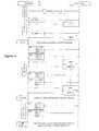
- FIG. 2shows a system in accordance with an embodiment of the present invention.
- FIG. 3shows an explicit transmission feedback system in accordance with an embodiment of the present invention.
- FIG. 4shows a timeline of the operation of the system in accordance with an embodiment of the present invention.
- the present disclosurerelates to a method and system for closed loop beamforming for MIMO OFDM wireless communication systems.
- the following descriptionis presented to enable one of ordinary skill in the art to make and use the invention and is provided in the context of a patent application and its requirements.
- Various modifications to the preferred embodiment and the generic principles and features described hereinwill be readily apparent to those skilled in the art.
- the present inventionis not intended to be limited to the embodiment shown but is to be accorded the widest scope consistent with the principles and features described herein.
- a method and system for closed loop beamforming for MIMO OFDM wireless communication systemsis disclosed.
- Well-defined metricsare utilized to indicate a change in the channel state, and apply a new sounding packet in order to update the beamforming parameters.
- Using periodic soundingschanging channel conditions are thus automatically detected and compensated.
- the advantageis that the link stability is improved, and high throughput with active beamforming is maintained.
- the system in accordance with the present inventioncan take the form of an entirely hardware implementation, an entirely software implementation, or an implementation containing both hardware and software elements.
- this detection procedureis implemented in software, which includes, but is not limited to, application software, firmware, resident software, microcode, etc.
- a computer-usable or computer-readable mediumcan be any apparatus that can contain, store, communicate, propagate, or transport the program for use by or in connection with the instruction execution system, apparatus, or device.
- the mediumcan be an electronic, magnetic, optical, electromagnetic, infrared, or semiconductor system (or apparatus or device) or a propagation medium.
- Examples of a computer-readable mediuminclude a semiconductor or solid state memory, magnetic tape, a removable computer diskette, a random access memory (RAM), a read-only memory (ROM), a rigid magnetic disk, and an optical disk.
- Current examples of optical disksinclude DVD, compact disk-read-only memory (CD-ROM), and compact disk—read/write (CD-R/W).
- FIG. 1shows a flowchart of a method in accordance with an embodiment of the present invention.
- Step 110involves initiating beamforming on a communication channel between the transmitter and the receiver.
- a second step 120involves monitoring the communication channel.
- a third step 130involves periodically determining a condition of the communication channel.
- a final step 140includes controlling beamforming based on the condition of the communication channel.
- FIG. 2shows a system 200 in accordance with an embodiment of the present invention.
- the system 200includes a transmitter 210 and a receiver 220 capable of communicated via a communication channel 215 . Additionally, the transmitter 210 and the receiver 220 include respective software (S/W) layers and Media Access Control (MAC) layers.
- the feedback signals 230are depicted in the upper middle block.
- the system 200includes features compliant with the 802.11nD4.0 standard to improve the performance of MIMO transmission.
- Two features described hereare fast link adaptation (FLA), and explicit transmit beamforming (eTxBF).
- FLAfast link adaptation
- eTxBFexplicit transmit beamforming
- the FLA mechanismis intended to improve system throughput and robustness by providing a protocol for CSI at the receiver 220 to assist the transmitter 210 in selecting an ideal Modulation and Coding Scheme (MCS) under the present channel conditions.
- MCSModulation and Coding Scheme
- the feedback mechanismis an MCS recommendation, or MCS feedback (MFB).
- the eTxBF mechanismis intended to improve MIMO performance by transmitting multi-stream data packets using beamforming, or beamsteering matrices for each subcarrier that will maximize the received signal strength, and assist in the subsequent equalization at the receiver 220 .
- FLAFast Link Adaptation
- MCSModulation and Coding Scheme
- the receiverupon receiving a MIMO packet, the receiver will compute an estimated SNR per spatial stream. This will be reported to the MAC layer 221 , which will pass this information to the receiver software layer 212 .
- the softwarewill convert this SNR information into an MCS recommendation, and send it back to the transmitter 210 .
- the softwareshall monitor the recommendations and adjust the MCS of the transmitted packets accordingly.
- the receiver 220For explicit beamforming, the receiver 220 , or beamformee, computes the beamsteering matrix V and sends it back to the transmitter 210 , or beamformer.
- the receiver 220will compute both uncompressed and compressed versions of the beamforming matrix, for each subcarrier.
- the MAC 211will decode the sounding packet and determine which format the particular beamformer supports, and send the proper format in the training response packet.
- the transmissionwill include a corresponding SNR that will predict the signal quality of the subsequent beamformed packets.
- the software 212will monitor the SNR levels to determine whether or not the training response should be used to update, or replace, the current beamforming parameters. Changing channel conditions will cause the MFB to degrade for the active beamforming parameters, and thus trigger an update, or sounding request for a new set of beamforming matrices.
- the system 300includes a transmitter 310 and a receiver 320 and a communication channel 316 there between.
- the transmitter 310includes a MAC and baseband processor (MAC/BBP) module 311 , an MCS Selection module 312 and a transmission Beamforming (TxBF) Steering Info module 313 .
- the receiveralso includes a baseband processor (BBP) module 321 and a MAC module 322 . Also shown is the sounding response computation module 314 and the MFB estimator 315 .
- the MAC/BB module 311prepares packets for transmission by selecting the latest MCS value for the packet recipient from the MCS Selection module 312 .
- the MAC/BB module 311retrieves the beamsteering matrices for the particular recipient from the TxBF Steering Info module 313 . If the corresponding user entry in module 313 contains a valid beamsteering set, then the outgoing beamforming processing is performed.
- TxBF controlwill work in parallel with the link adaptation, which utilizes MFB signals to control the modulation (data rate) of the current communication link.
- the transmitter 310will monitor the current status of the data link by issuing periodic MHQ packets.
- the transmitter 310 software moduleswill process the SNR values in the MIMO sounding response, and convert this to an equivalent MCS value that corresponds to the set of associated beamsteering matrices.
- the TxBFWhen the beamsteering MCS computed is detected to be higher than current MFB value, the TxBF shall be activated, loading the beamsteering matrices into the baseband and the new MCS shall be used.
- the loaded beamforming matricesmay be from a sounding packet sent after the MCS change was detected.
- the MFB from the subsequent soundingshall be qualified to guarantee that the new MCS still triggers, or satisfies, the rate change criteria.
- the closed loop TxBF/MFB operationcan be further detailed using a timeline, as shown in FIG. 4 .
- the beamformer and beamformeeestablish a link through association, and make a capabilities exchange.
- the beamformer(on the left) is aware that the associated client is supports MFB/MRQ, and commences MFB requests (MRQ), and the beginning of FLA Startup, as shown in FIG. 2 .
- the current/existing rate adaptation algorithmshall control the rate adaptation.
- a stable MFBcan be determined, as an example, by monitoring the statistical mean and variance of the MCS values being returned. If the mean and variance are within some pre-set bounds, then the MFB link can be assumed to be sufficiently stable for closed-loop FLA operation.
- the beamformerissues both MRQ and sounding packets.
- the beamformeruses the MIMO control frame SNR information to determine the equivalent MCS (or SNDG_MCS).
- the beamformermay activate the beamforming, by enabling the MAC/BB 311 to load the beamsteering matrices into the TxBF Steering Info module 313 and begin beamforming using the associated MCS value from the MCS selection module 312 . Then, TxBF is enabled, or active.
- the softwaremay issue another MRQ DP/SNDG NDP, and use the beamforming matrices from the subsequent response in order to initiate a TxBF profile update.
- TAWWhile the TAW is active, subsequent DP-MRQ packets will have TxBF active, and the subsequent MFB will monitor the status of the TxBF link.
- the corresponding NDP-SNDG packetswill have TxBF not active, and will provide the SNDG_MCS values. These SNDG_MCS values will be used to update the TxBF profile, in a mariner identical to the initial activation of the TxBF mode.
- the closed loop beamforming operationis accomplished using parallel MFB, and sounding packet responses.
- the quality of the beamforming operationis assessed by monitoring the MFB of the beamformed packet, while the typically lower rate sounding packets were sent unbeamformed.
- the controlcan be accomplished without utilizing MFB, and the periodic sounding can include beamformed sounding packets.
- the sounding responsesare computed in element 314 .
- the MFB equivalent estimateis computed in element 315 using both the beamformed and non-beamformed response metrics.
- the advantage of this implementationis that the MFB comparison is done in a central location (at the transmitter 310 ), so the metrics can be computed with the same algorithm.
- MFB computed at the receiver 320may use a different algorithm resulting in inconsistent recommendations.
- this optional approachhas the advantage of separating the MFB function from the beamforming response, so that beamforming can be effectively implemented in systems where the receiver does not support MFB.
- a method and system for closed loop beamforming for MIMO OFDM wireless communication systemsis disclosed.
- Well-defined metricsare utilized to indicate a change in the channel state, and apply a new sounding packet in order to update the beamforming parameters.
- Using periodic soundingschanging channel conditions are thus automatically detected and compensated.
- the advantageis that the link stability is improved, and high throughput with active beamforming is maintained.
Landscapes
- Engineering & Computer Science (AREA)
- Computer Networks & Wireless Communication (AREA)
- Signal Processing (AREA)
- Mobile Radio Communication Systems (AREA)
- Radio Transmission System (AREA)
Abstract
Description
Claims (9)
Priority Applications (2)
| Application Number | Priority Date | Filing Date | Title |
|---|---|---|---|
| US12/500,154US8687717B2 (en) | 2009-01-06 | 2009-07-09 | Method and apparatus for closed loop beamforming in wireless communication systems |
| TW098134938ATW201027941A (en) | 2009-01-06 | 2009-10-15 | Method and apparatus for closed loop beamforming in a wireless communication system |
Applications Claiming Priority (2)
| Application Number | Priority Date | Filing Date | Title |
|---|---|---|---|
| US14286709P | 2009-01-06 | 2009-01-06 | |
| US12/500,154US8687717B2 (en) | 2009-01-06 | 2009-07-09 | Method and apparatus for closed loop beamforming in wireless communication systems |
Publications (2)
| Publication Number | Publication Date |
|---|---|
| US20100172425A1 US20100172425A1 (en) | 2010-07-08 |
| US8687717B2true US8687717B2 (en) | 2014-04-01 |
Family
ID=42311683
Family Applications (1)
| Application Number | Title | Priority Date | Filing Date |
|---|---|---|---|
| US12/500,154Active2030-12-11US8687717B2 (en) | 2009-01-06 | 2009-07-09 | Method and apparatus for closed loop beamforming in wireless communication systems |
Country Status (2)
| Country | Link |
|---|---|
| US (1) | US8687717B2 (en) |
| TW (1) | TW201027941A (en) |
Cited By (5)
| Publication number | Priority date | Publication date | Assignee | Title |
|---|---|---|---|---|
| US20130155889A1 (en)* | 2011-12-19 | 2013-06-20 | Bandwidth.Com, Inc. | Intelligent multi-streaming for enhancing or avoiding dropped and interrupted communication sessions |
| US20130170452A1 (en)* | 2012-01-04 | 2013-07-04 | Futurewei Technologies, Inc. | Low Complexity Beamforming Scheme |
| US8913582B1 (en)* | 2009-03-05 | 2014-12-16 | Marvell International Ltd. | Systems and methods for selecting a modulation and coding scheme for wireless communication between wireless devices in a wireless network |
| US8982803B1 (en) | 2009-03-05 | 2015-03-17 | Marvell International Ltd. | Systems and methods for link adaption in wireless communication systems |
| US9425872B1 (en)* | 2009-09-23 | 2016-08-23 | Marvell International Ltd. | Transparent implicit beamforming in a communication system |
Families Citing this family (14)
| Publication number | Priority date | Publication date | Assignee | Title |
|---|---|---|---|---|
| US8175538B1 (en) | 2008-12-15 | 2012-05-08 | Qualcomm Atheros, Inc. | Calibrating a wireless communication device |
| US8804612B1 (en) | 2009-02-06 | 2014-08-12 | Qualcomm Incorporated | Triggering and transmitting sounding packets for wireless communications |
| US8295263B1 (en)* | 2009-02-06 | 2012-10-23 | Qualcomm Atheros, Inc. | Triggering and transmitting sounding packets for wireless communications |
| US9444577B1 (en)* | 2010-04-05 | 2016-09-13 | Marvell International Ltd. | Calibration correction for implicit beamformer using an explicit beamforming technique in a wireless MIMO communication system |
| US8873531B2 (en) | 2010-05-03 | 2014-10-28 | Intel Corporation | Device, system and method of indicating station-specific information within a wireless communication |
| WO2011116727A2 (en) | 2011-04-29 | 2011-09-29 | 华为技术有限公司 | Transmission method, apparatus and system for uplink transmission diversity |
| US8891640B2 (en)* | 2011-06-21 | 2014-11-18 | Marvell World Trade Ltd. | Uplink training for MIMO implicit beamforming |
| US9154969B1 (en) | 2011-09-29 | 2015-10-06 | Marvell International Ltd. | Wireless device calibration for implicit transmit |
| US9160435B2 (en) | 2011-12-13 | 2015-10-13 | Intel Corporation | Beamforming based on information from platform sensors |
| US9369188B2 (en)* | 2011-12-13 | 2016-06-14 | Intel Corporation | Link prediction based re-beamforming triggering algorithm for 60 ghz communication links |
| US9237464B2 (en) | 2012-01-21 | 2016-01-12 | Huawei Technologies Co., Ltd. | Transmission method, apparatus, and system for uplink transmit diversity |
| US9661579B1 (en) | 2013-05-03 | 2017-05-23 | Marvell International Ltd. | Per-tone power control in OFDM |
| US9843097B1 (en) | 2013-07-08 | 2017-12-12 | Marvell International Ltd. | MIMO implicit beamforming techniques |
| US12244417B2 (en) | 2019-12-20 | 2025-03-04 | Qualcomm Incorporated | Link adaptation protocol in a wireless local area network (WLAN) |
Citations (6)
| Publication number | Priority date | Publication date | Assignee | Title |
|---|---|---|---|---|
| US20060098580A1 (en)* | 2004-11-08 | 2006-05-11 | Qinghua Li | Apparatus and method capable of beam forming adjustments |
| US20060209712A1 (en)* | 2005-03-09 | 2006-09-21 | Yuichi Morioka | Wireless communication system, wireless communication apparatus, wireless communication method, and computer program |
| US20070147535A1 (en)* | 2005-12-22 | 2007-06-28 | Samsung Electronics Co., Ltd. | Method for rate adaptation with extended MCS set for wideband eigen-beamforming transmission |
| US20070195974A1 (en)* | 2006-02-09 | 2007-08-23 | Qinghua Li | Mimo communication system and method for beamforming using polar-cap codebooks |
| US20070223422A1 (en)* | 2006-03-20 | 2007-09-27 | Byoung-Hoon Kim | Resource allocation to support single-user and multi-user mimo transmission |
| WO2007114804A1 (en)* | 2006-03-30 | 2007-10-11 | Mitsubishi Electric Research Laboratories | Antenna/beam selection training in mimo wireless lans with different sounding frames |
- 2009
- 2009-07-09USUS12/500,154patent/US8687717B2/enactiveActive
- 2009-10-15TWTW098134938Apatent/TW201027941A/enunknown
Patent Citations (6)
| Publication number | Priority date | Publication date | Assignee | Title |
|---|---|---|---|---|
| US20060098580A1 (en)* | 2004-11-08 | 2006-05-11 | Qinghua Li | Apparatus and method capable of beam forming adjustments |
| US20060209712A1 (en)* | 2005-03-09 | 2006-09-21 | Yuichi Morioka | Wireless communication system, wireless communication apparatus, wireless communication method, and computer program |
| US20070147535A1 (en)* | 2005-12-22 | 2007-06-28 | Samsung Electronics Co., Ltd. | Method for rate adaptation with extended MCS set for wideband eigen-beamforming transmission |
| US20070195974A1 (en)* | 2006-02-09 | 2007-08-23 | Qinghua Li | Mimo communication system and method for beamforming using polar-cap codebooks |
| US20070223422A1 (en)* | 2006-03-20 | 2007-09-27 | Byoung-Hoon Kim | Resource allocation to support single-user and multi-user mimo transmission |
| WO2007114804A1 (en)* | 2006-03-30 | 2007-10-11 | Mitsubishi Electric Research Laboratories | Antenna/beam selection training in mimo wireless lans with different sounding frames |
Cited By (6)
| Publication number | Priority date | Publication date | Assignee | Title |
|---|---|---|---|---|
| US8913582B1 (en)* | 2009-03-05 | 2014-12-16 | Marvell International Ltd. | Systems and methods for selecting a modulation and coding scheme for wireless communication between wireless devices in a wireless network |
| US8982803B1 (en) | 2009-03-05 | 2015-03-17 | Marvell International Ltd. | Systems and methods for link adaption in wireless communication systems |
| US9425872B1 (en)* | 2009-09-23 | 2016-08-23 | Marvell International Ltd. | Transparent implicit beamforming in a communication system |
| US20130155889A1 (en)* | 2011-12-19 | 2013-06-20 | Bandwidth.Com, Inc. | Intelligent multi-streaming for enhancing or avoiding dropped and interrupted communication sessions |
| US9014038B2 (en)* | 2011-12-19 | 2015-04-21 | Bandwidth.Com, Inc. | Intelligent multi-streaming for enhancing or avoiding dropped and interrupted communication sessions |
| US20130170452A1 (en)* | 2012-01-04 | 2013-07-04 | Futurewei Technologies, Inc. | Low Complexity Beamforming Scheme |
Also Published As
| Publication number | Publication date |
|---|---|
| TW201027941A (en) | 2010-07-16 |
| US20100172425A1 (en) | 2010-07-08 |
Similar Documents
| Publication | Publication Date | Title |
|---|---|---|
| US8687717B2 (en) | Method and apparatus for closed loop beamforming in wireless communication systems | |
| US9425872B1 (en) | Transparent implicit beamforming in a communication system | |
| US20100296564A1 (en) | Method and apparatus for performing multi-antenna transmission | |
| JP5384680B2 (en) | Calibration and beamforming of wireless communication systems | |
| US8842587B2 (en) | Wireless channel calibration | |
| KR101585845B1 (en) | Method and system for dual-mode (single user and multi users) packet error rate based rate control in a wireless communication system | |
| JP2018113700A (en) | Update of mu-mimo adaptive algorithm | |
| US20230291441A1 (en) | Signaling to aid enhanced nr type ii csi feedback | |
| US20150333812A1 (en) | Method and apparatus for supporting adaptive channel state information feedback rate in multi-user communication systems | |
| US20110299480A1 (en) | Method and apparatus for supporting adaptive channel state information feedback rate in multi-user communication systems | |
| US9485674B2 (en) | Method and system for unified rate adaptation for SU-BF and MU-MIMO operation | |
| JP2009510898A (en) | Training signal for selecting antenna and beam in MIMO wireless LAN | |
| KR20120089860A (en) | Physical layer metrics to support adaptive station-dependent channel state information feedback rate in multi-user communication systems | |
| JP2009526434A (en) | Antenna / beam selection training in MIMO wireless LAN with various sounding frames | |
| JP2016197875A (en) | Device for sending and receiving quantization quality feedback | |
| US20110200139A1 (en) | Multiple-input multiple-output systems and methods for wireless communication thereof for reducing the quantization effect of precoding operations utilizing a finite codebook | |
| WO2012163148A1 (en) | Link adaptive feedback method and transmission-end device | |
| US11817974B2 (en) | Sounding-interval adaptation using link quality | |
| TWI533515B (en) | Antenna diversity and beamforming coexistence method and machine readable media | |
| AU2011235950B2 (en) | Calibration and beamforming in a wireless communication system | |
| WO2011157176A2 (en) | Pre-coding method and transmitter used in distributed multiple input multiple output system | |
| CN112688727A (en) | Wireless communication method, base station equipment and storage medium | |
| JP2011254550A (en) | Method for selecting antenna in multiple-input multiple-output wireless local-area network |
Legal Events
| Date | Code | Title | Description |
|---|---|---|---|
| AS | Assignment | Owner name:RALINK TECHNOLOGY CORPORATION, TAIWAN Free format text:ASSIGNMENT OF ASSIGNORS INTEREST;ASSIGNORS:PARE, THOMAS EDWARD, JR;WONG, JOHN;REEL/FRAME:022934/0872 Effective date:20090625 | |
| AS | Assignment | Owner name:MEDIATEK INC., TAIWAN Free format text:ASSIGNMENT OF ASSIGNORS INTEREST;ASSIGNOR:RALINK TECHNOLOGY (SINGAPORE) CORPORATION;REEL/FRAME:026992/0524 Effective date:20110929 | |
| STCF | Information on status: patent grant | Free format text:PATENTED CASE | |
| FEPP | Fee payment procedure | Free format text:PAYOR NUMBER ASSIGNED (ORIGINAL EVENT CODE: ASPN); ENTITY STATUS OF PATENT OWNER: LARGE ENTITY | |
| MAFP | Maintenance fee payment | Free format text:PAYMENT OF MAINTENANCE FEE, 4TH YEAR, LARGE ENTITY (ORIGINAL EVENT CODE: M1551) Year of fee payment:4 | |
| MAFP | Maintenance fee payment | Free format text:PAYMENT OF MAINTENANCE FEE, 8TH YEAR, LARGE ENTITY (ORIGINAL EVENT CODE: M1552); ENTITY STATUS OF PATENT OWNER: LARGE ENTITY Year of fee payment:8 | |
| MAFP | Maintenance fee payment | Free format text:PAYMENT OF MAINTENANCE FEE, 12TH YEAR, LARGE ENTITY (ORIGINAL EVENT CODE: M1553); ENTITY STATUS OF PATENT OWNER: LARGE ENTITY Year of fee payment:12 |