US8687312B1 - Edge detection for disk drives - Google Patents
Edge detection for disk drivesDownload PDFInfo
- Publication number
- US8687312B1 US8687312B1US12/957,152US95715210AUS8687312B1US 8687312 B1US8687312 B1US 8687312B1US 95715210 AUS95715210 AUS 95715210AUS 8687312 B1US8687312 B1US 8687312B1
- Authority
- US
- United States
- Prior art keywords
- signal
- disk
- values
- recording head
- edge
- Prior art date
- Legal status (The legal status is an assumption and is not a legal conclusion. Google has not performed a legal analysis and makes no representation as to the accuracy of the status listed.)
- Expired - Fee Related, expires
Links
- 238000003708edge detectionMethods0.000titleclaimsdescription48
- 238000000034methodMethods0.000claimsabstractdescription58
- 230000008569processEffects0.000claimsabstractdescription43
- 230000003044adaptive effectEffects0.000claimsabstractdescription13
- 230000003993interactionEffects0.000claimsdescription20
- 230000003252repetitive effectEffects0.000claimsdescription19
- 230000004044responseEffects0.000claimsdescription9
- 238000002347injectionMethods0.000abstractdescription7
- 239000007924injectionSubstances0.000abstractdescription7
- 230000000737periodic effectEffects0.000description5
- 230000002452interceptive effectEffects0.000description4
- 238000001514detection methodMethods0.000description3
- 238000004519manufacturing processMethods0.000description3
- 230000003534oscillatory effectEffects0.000description2
- 238000004364calculation methodMethods0.000description1
- 230000008859changeEffects0.000description1
- 230000003287optical effectEffects0.000description1
- 238000005096rolling processMethods0.000description1
- 239000007787solidSubstances0.000description1
- 230000001960triggered effectEffects0.000description1
Images


Classifications
- G—PHYSICS
- G11—INFORMATION STORAGE
- G11B—INFORMATION STORAGE BASED ON RELATIVE MOVEMENT BETWEEN RECORD CARRIER AND TRANSDUCER
- G11B5/00—Recording by magnetisation or demagnetisation of a record carrier; Reproducing by magnetic means; Record carriers therefor
- G11B5/48—Disposition or mounting of heads or head supports relative to record carriers ; arrangements of heads, e.g. for scanning the record carrier to increase the relative speed
- G11B5/58—Disposition or mounting of heads or head supports relative to record carriers ; arrangements of heads, e.g. for scanning the record carrier to increase the relative speed with provision for moving the head for the purpose of maintaining alignment of the head relative to the record carrier during transducing operation, e.g. to compensate for surface irregularities of the latter or for track following
- G11B5/596—Disposition or mounting of heads or head supports relative to record carriers ; arrangements of heads, e.g. for scanning the record carrier to increase the relative speed with provision for moving the head for the purpose of maintaining alignment of the head relative to the record carrier during transducing operation, e.g. to compensate for surface irregularities of the latter or for track following for track following on disks
- G11B5/59633—Servo formatting
- G11B5/59666—Self servo writing
- G—PHYSICS
- G11—INFORMATION STORAGE
- G11B—INFORMATION STORAGE BASED ON RELATIVE MOVEMENT BETWEEN RECORD CARRIER AND TRANSDUCER
- G11B5/00—Recording by magnetisation or demagnetisation of a record carrier; Reproducing by magnetic means; Record carriers therefor
- G11B5/48—Disposition or mounting of heads or head supports relative to record carriers ; arrangements of heads, e.g. for scanning the record carrier to increase the relative speed
- G11B5/58—Disposition or mounting of heads or head supports relative to record carriers ; arrangements of heads, e.g. for scanning the record carrier to increase the relative speed with provision for moving the head for the purpose of maintaining alignment of the head relative to the record carrier during transducing operation, e.g. to compensate for surface irregularities of the latter or for track following
- G11B5/596—Disposition or mounting of heads or head supports relative to record carriers ; arrangements of heads, e.g. for scanning the record carrier to increase the relative speed with provision for moving the head for the purpose of maintaining alignment of the head relative to the record carrier during transducing operation, e.g. to compensate for surface irregularities of the latter or for track following for track following on disks
- G11B5/59627—Aligning for runout, eccentricity or offset compensation
- G—PHYSICS
- G11—INFORMATION STORAGE
- G11B—INFORMATION STORAGE BASED ON RELATIVE MOVEMENT BETWEEN RECORD CARRIER AND TRANSDUCER
- G11B5/00—Recording by magnetisation or demagnetisation of a record carrier; Reproducing by magnetic means; Record carriers therefor
- G11B5/48—Disposition or mounting of heads or head supports relative to record carriers ; arrangements of heads, e.g. for scanning the record carrier to increase the relative speed
- G11B5/58—Disposition or mounting of heads or head supports relative to record carriers ; arrangements of heads, e.g. for scanning the record carrier to increase the relative speed with provision for moving the head for the purpose of maintaining alignment of the head relative to the record carrier during transducing operation, e.g. to compensate for surface irregularities of the latter or for track following
- G11B5/596—Disposition or mounting of heads or head supports relative to record carriers ; arrangements of heads, e.g. for scanning the record carrier to increase the relative speed with provision for moving the head for the purpose of maintaining alignment of the head relative to the record carrier during transducing operation, e.g. to compensate for surface irregularities of the latter or for track following for track following on disks
- G11B5/59633—Servo formatting
- G11B5/59661—Spiral servo format
Definitions
- This disclosurerelates to disk drives. More particularly, this disclosure relates to edge detection techniques usable in some embodiments to determine the valid track range of one or more disks of a disk drive.
- servo sectorsare typically written to a disk to define a plurality of evenly-spaced, concentric tracks.
- Servo writersare typically used to write the servo sectors to the disk during disk drive manufacturing.
- Servo writersoften employ extremely accurate head positioning mechanics, such as laser interferometers or optical encoders, to ensure that the servo sectors are written at the proper radial location, typically, from the inner diameter of the disk to the outer diameter of the disk.
- extremely accurate clocking systemsmay be utilized in order to write the servo sectors in the proper circumferential locations on the disk.
- disk drivesmay perform self servo-writing in which the disk drive itself writes the servo sectors to the disk.
- the range of usable disk space between the inner diameter (ID) and the outer diameter (OD) of disk drivescan vary.
- FIG. 1Ashows an example disk drive that implements edge detection according to an embodiment.
- FIG. 1Bshows an enlarged view of an example disk of the disk drive of FIG. 1A incorporating eccentrically arranged spiral reference patterns.
- FIG. 2illustrates one implementation of a portion of the controller of FIG. 1A .
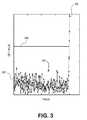
- FIG. 3illustrates a plot showing example data samples used in an edge detection process according to an embodiment.
- FIG. 4illustrates an example process for performing edge detection.
- Embodiments described hereininclude systems and methods for determining one or more edges of usable portions of a disk drive. Such knowledge can be used to determine a range of usable space (e.g., valid tracks) of the disk, thereby improving utilization of available disk space.
- a range of usable spacee.g., valid tracks
- Specific embodiments of systems and processeswill now be described with reference to the drawings. This description is intended to illustrate specific embodiments of the inventions, and is not intended to be limiting. Thus, nothing in this description is intended to imply that any particular component, step or characteristic is essential. The inventions are defined only by the claims.
- FIG. 1Ashows an example disk drive 118 coupled to an external servo writer 130 usable for writing spiral reference patterns 136 0 - 136 7 ( FIG. 1B ) to a disk 116 of the drive 118 .
- the spiral reference patterns(servo spiral seeds) may include reference servo bursts that can be used for forming product servo bursts.
- the disk drive 118includes controller 120 having an edge detection module 121 , and a head disk assembly (HDA) 122 .
- HDAhead disk assembly
- the HDAcomprises the disk 116 , an actuator arm 124 , a head 126 connected to a distal end of the actuator arm 124 , and a voice coil motor 128 for rotating the actuator arm 124 about a pivot to position the head 126 radially over the disk 116 .
- the external spiral servo writer 130may be used to control a radial location of the head 126 for writing a plurality of the spiral reference patterns 136 0 - 136 7 between an inner radial location 131 and an outer radial location 132 on the disk 116 . While only one disk 116 is shown in FIG. 1B , the drive 118 may include a platter of disks 116 arranged in a vertical stack as shown in FIG. 1A .
- a head positioning pin 133 of the external spiral servo writer 130may be inserted into the HDA 122 before writing the spiral reference patterns.
- the head positioning pin 133may be used for engaging the actuator arm 124 .
- the external spiral servo writer 130includes head positioning mechanics 134 used to derive a radial location of the head 126 .
- the head positioning pin 133is actuated in response to the radial location of the head 126 in a closed loop system in order to position the head 126 radially over the disk 116 while writing a plurality of reference servo bursts to the disk along a plurality of substantially spiral paths to form the plurality of spiral reference patterns 136 0 - 136 7 as illustrated in FIG. 1B .
- the drive 118further includes a ramp 148 and a crash stop (not shown).
- the ramp 148is positioned near the outer diameter of the disk and configured to load and unload the head 126 to and from the disk 116 .
- the crash stop(not shown) can include a structure positioned near the center of the disk generally configured to limit movement of the head near the inner diameter of the disk.
- the edge detection module 121 of the controller 120implements a process to determine one or more edges of a usable region of the disk drive by detecting interaction of the recording head 126 with the ramp 148 and/or crash stop.
- the patterns 136may be off-center with respect to the center of rotation 133 of the disk 116 .
- the disk(s) 116when installed in the drive, it may be mounted such that the pre-written spirals are off-center with respect to the drive spindle.
- a corresponding eccentricity 150is associated with the disk 116 .
- the controller 120can be configured to counteract the eccentricity 159 during drive operation.
- adaptive feed-forward control (AFC)can be implemented by the controller 120 to counteract eccentricity and/or provide other error correction.
- the controllerimplements AFC by introducing repetitive motion (e.g., back and forth motion, oscillatory motion, periodic motion, and/or motion otherwise including significant frequency content) into the drive head trajectory that causes the drive head to follow the eccentrically written tracks during disk rotation.
- repetitive motione.g., back and forth motion, oscillatory motion, periodic motion, and/or motion otherwise including significant frequency content
- FIG. 2shows a portion 220 of an example disk drive controller in accordance with some embodiments.
- the embodiment shown in FIG. 2may form a portion of the controller 120 of the disk drive 118 of FIG. 1 .
- the controller 220processes a read signal 234 to generate a position error signal (PES) 262 .
- the PES 262can be filtered with a suitable compensation filter to generate a control signal 236 applied to a voice coil motor (VCM) 221 , which rotates an actuator arm 124 about a pivot in order to position the head 126 radially over the disk 116 in a direction that reduces the PES.
- VCMvoice coil motor
- a microactuator(not shown, e.g., a piezoelectric actuator) may also be incorporated in some embodiments in combination with the VCM 220 to improve tracking performance.
- the AFC module 240produces an AFC injection signal 242 .
- the AFC injection signal 242is combined 244 with a VCM control signal 246 generated by a VCM compensator 248 .
- the estimated position 256is compared 258 to a reference position 60 to generate the PES 262 .
- the AFC module 240processes the PES 262 to adapt the coefficients of the AFC injection signal 242 .
- the PES 262is also processed by the VCM compensator 248 to generate the VCM control signal 246 .
- the controller 220combines the output 246 of the VCM compensator 248 with the AFC injection signal 242 to generate the VCM control signal 246 .
- interaction of the recording head 126 with one or more of the ramp 148 and crash stopcauses a disturbance in the repeatable motion of the head 126 , and a corresponding change in the AFC injection signal 242 .
- the edge detection module 121can be configured to detect such disturbances to identify edges of usable portions the disk.
- the edge detection processinvolves performing a frequency transform on values of a signal in the control path of the disk drive 118 .
- the edge detection module 121may determine a deviation in a repetitive motion (e.g., back and forth motion, oscillatory motion, periodic motion, and/or motion otherwise including significant frequency content) of the head 126 , where the deviation is caused by interaction between the head 126 and the ramp 148 and/or crash stop (or other appropriate motion-limiting structure).
- a repetitive motione.g., back and forth motion, oscillatory motion, periodic motion, and/or motion otherwise including significant frequency content
- the edge detection processadvantageously allows for relatively precise and robust detection of head interaction with the ramp 148 and/or crash stop. Moreover, because of the improved precision and reliability of the process, edge detection techniques described herein involve relatively low risk of damage to drive components during the detection process. Thus, the drive 118 can employ such techniques to safely and accurately determine valid track range or otherwise determine the boundaries of usable drive space. Moreover, because the edge detection processes described herein can in some cases be implemented in firmware with little or no added hardware, they can be incorporated at minimal cost.
- the edge detection processwill now be described with respect to an illustrative example for the purposes of illustration.
- the exampleis described with respect to a scenario where the edge detection module 121 detects an outer edge of a usable region of the disk based on interaction between the head 128 and the ramp 148 .
- the processcan be used to detect an inner edge based on interaction between the head 126 and the crash stop.
- the edge detection module 121detects interaction between some other portion of the arm 124 instead of, or in addition to, the recording head 126 .
- the edge detection module 121processes the AFC signal 242 to detect the ramp and/or crash stop disturbance.
- Other signalscan be used instead of or in addition to the AFC signal 242 .
- the PES signal 262can be used.
- the AFC module 242can be configured to inject the AFC signal 242 (e.g., a sinusoidal or other or substantially periodic signal) into the VCM control path to cause the head 126 to move according to a predetermined, repetitive trajectory so as to counteract the eccentricity of the disk 116 .
- the AFC module 240is configured to adaptively adjust to (learn) such changes in head 126 trajectory.
- the edge detection module 121is configured to detect this deviation by comparing values derived from the AFC signal 242 with an established threshold.
- the edge detection module 121performs a single frequency discrete Fourier transform (DFT) on values of the AFC signal 242 and analyzes the magnitudes of the DFT values, although a variety of other operations are possible. For example, other types of frequency transforms or other appropriate mathematical operations may be implemented.
- the phase of a frequency transform (e.g., DFT) operationis used instead of, or in combination with the magnitude.
- a cross-correlation operationis employed.
- a threshold cross-correlationis established by calculating the cross-correlation between sets of signal values (e.g., PES or AFC signal values corresponding to one or more revolutions) taken at a plurality of locations spaced from the edge of the disk 116 . These sets of signal values taken away from the edge are likely to have a relatively high correlation. As the head 126 is actuated towards the edge of the disk 118 , the cross-correlation is iteratively performed and will drop below the established threshold upon sufficient interaction between the head 126 and the ramp 148 or crash-stop.
- the example disk drive 116implements adaptive feed-forward control
- other types of control schemesare compatible with embodiments described in the disclosure, such as feed-back or non-adaptive control algorithms.
- the detection module 121processes values the AFC signal 242 for values corresponding to head 126 positions spaced from the ramp 148 .
- the thresholdis established while there is no significant interaction between the head 126 and the ramp 148 .
- the average of a number of DFT samples corresponding to one revolution of the diskis calculated, and the threshold is set at three times the calculated average.
- the thresholdmay be determined using more or less samples or a higher or lower threshold (e.g., 1, 2, 4, 5, 10 or more times the calculated average), a standard deviation or other appropriate operation can be used, etc. In some cases, a maximum or minimum value may be used instead of an average.
- a sliding window thresholdis implemented. In such a configuration, the threshold is iteratively recalculated based on a predetermined number of samples in the window (e.g., the previous 10 or 20 samples) as the head 126 moves towards the ramp 148 (or crash stop).
- FIG. 3illustrates a plot 300 showing DFT values 302 processed by an edge detection module 121 in accordance with certain embodiments.
- each DFT values 302corresponds to one or more head 126 positions (e.g., tracks), and extend from the leftmost DFT value 304 corresponding to a head 126 position farthest from the ramp 148 to the rightmost DFT value 306 corresponding to a head 126 position nearest the ramp 148 .
- the DFT values 302exceed the established threshold 308 due to the ramp 148 /head 126 interference.
- the edge of the disk 116may correspond to the current head 126 position which resulted in the threshold condition being triggered.
- the edge of the disk 116corresponds to a position on the disk 116 that is spaced a predetermined radial distance away from the current head 126 position (e.g., towards the center of the disk 116 ), thereby providing greater margin between the ramp 148 and the edge.
- the marginis 100 tracks from the head position corresponding to the threshold trigger condition, although other values are possible (e.g., 5, 10, 50, 200, 500, 1000 or more tracks).
- the edge detection module 121detects and records the position of the inner edge of the disk 116 in a similar fashion but by moving the head 126 towards the center of the disk 116 to detect interaction between the head 126 and the crash stop. Once both edges are established, the controller 120 can calculate a valid track range by calculating the number of tracks between the first edge and the second edge, or by performing some other appropriate calculation.
- the AFC injection module 240can be configured to adapt to select frequency content of interfering signals.
- the AFC module 240adapts to portions of interfering signals corresponding to particular harmonics (referred to herein as “AFC harmonics”), e.g., low order harmonics, of a selected fundamental frequency.
- AFC harmonicsparticular harmonics
- the edge detection module 121may advantageously utilize knowledge of what the AFC harmonics are in the edge detection process. For example, the edge detection module 121 may use DFT values (e.g., DFT power values) corresponding to this frequency content or a subset thereof.
- the AFC module 240adapts to frequency content corresponding to the 1st and 2nd harmonics of a selected fundamental frequency, and the edge detection module 121 uses DFT values corresponding to the 2nd harmonic in the edge detection process.
- the fundamental frequencyis equal to or derived from the frequency of disk 116 rotation.
- the fundamental frequencymay be equal to the number of revolutions of the disk 116 per second.
- the fundamental frequencymay be equal to a multiple of the disk rotation frequency (e.g., 1 ⁇ 4, 1 ⁇ 2, 2, 4, 8 or 10 times the disk rotation frequency).
- the PES signal 262is used.
- a frequency transform (e.g., DFT) other operationcan be performed on the PES signal 262 in a manner similar to the above example where the AFC signal 242 is used.
- a single DFTcan be performed on the PES signal 262 to detect head 126 /ramp 148 and/or head 126 /crash stop interaction.
- the AFC module 240will adaptively counteract disturbances in recording head 126 motion corresponding to certain frequency components, e.g., AFC harmonics.
- interfering signale.g., due to ramp and/or crash stop interaction
- the edge detection module 121can utilize PES signal 262 DFT values corresponding to frequency components included in the interfering signal but not accounted for by the AFC module 240 (e.g., non-AFC harmonics).
- the edge detection module 121uses PES signal 262 DFT values corresponding to one or more of the 3rd and 4th harmonics in the edge detection process.
- different frequency contente.g., non-AFC harmonics may be used.
- FIG. 4illustrates an embodiment of an example process for detecting an edge of a usable region of a disk 116 of a disk drive 118 .
- the processprocesses signal values for head 126 positions spaced from an edge of the disk 116 .
- the head 126may be positioned in a region generally between the inner and outer diameters of the disk 116 , for example, or in a region otherwise not in proximity to the edges, ramp 148 and/or crash stop.
- the usable region of the disk 116may encompass one or more portions of the disk 116 between the ramp 148 and the crash stop.
- the usable regionmay include disk portions 116 (e.g., tracks) sufficiently spaced from the ramp 148 and/or crash stop to allow proper operation of the recording head 126 during drive operation.
- a variety of signalscan be used in the edge detection process.
- the PES signal 262 or the AFC signal 242may be used.
- any signal usable to control actuation and/or determine the position of the recording head 126 with respect to the disk 116may be used in various configurations.
- a special reference signalmay be generated that is dedicated to the edge detection process, or some other pre-defined control path signal can be used.
- the spiral patterns 136are not written prior to assembly but are instead written after the disks 116 are assembled in the drive 116 , thereby reducing or eliminating eccentricity 150 .
- the AFC signal 242is not pre-configured to cause a repetitive trajectory of the head 126 to counteract the eccentricity 150 .
- a dedicated signale.g., a sinusoidal or other periodic or substantially periodic signal
- Such a signalcan be added to the PES signal 262 or to the VCM control input 236 , for example.
- the AFC 240will adapt to the injected signal, causing repetitive motion of the head 126 , which can be used as a reference in the edge detection process in the manner described herein.
- the edge detection module 121performs a frequency transform (e.g., DFT) on signal values corresponding to head 126 positions spaced from the disk edge.
- a frequency transforme.g., DFT
- the processestablishes the edge detection threshold. For example, as described above, the edge detection module 121 processes one or more of the transformed signal values according to a desired algorithm to generate the threshold.
- the selected algorithm used in the threshold determinationcan vary.
- the edge detection module 121may calculate an average, standard deviation, minimum or maximum, derivative, or the like on a select subset (e.g., a fixed or rolling window) of signal values to determine the threshold at block 404 .
- processcontinues to actuate the head 126 towards the edge of the disk 116 and continues to process signal values according to the selected algorithm, e.g., by performing a frequency transform on the signal values.
- the edge detection module 121compares the current signal values to the threshold condition to determine whether the threshold condition has been met.
- the processcan also include determining an edge of the usable region of the disk 116 in response to the threshold condition being satisfied.
- the first edgemay be an inner edge of the disk determined by detecting interaction of the recording head with a crash stop of the disk drive.
- the edge detection module 121may establish the edge at the current head 126 position, corresponding the threshold condition being satisfied, may be spaced from the current head 126 position by a predetermined margin, such as a number of tracks, or may be determined according to some other appropriate scheme.
- the processcan generally repeat to determine another edge of the disk.
- the second edgemay be an outer edge of the disk, for example, determined by detecting interaction of the disk with a ramp 148 .
- structures other than a crash stop and/or ramp 148may be used to delineate the inner and outer edges, respectively.
- the processcan additionally include calculating a valid track range at least in part based on the first edge and the second edge.
- the valid track rangemay include some or all of an annular region of the disk between the first edge and the second edge.
- the edge detection processes described hereinmay be implemented in firmware code executed by the controller 120 ; in application-specific circuitry of the controller 120 ; or a combination thereof. If implemented partly or wholly in firmware or other executable code, the executable code may be stored in any appropriate type of non-transitory computer readable medium, such as a solid state memory device.
Landscapes
- Moving Of The Head To Find And Align With The Track (AREA)
Abstract
Description
Claims (17)
Priority Applications (1)
| Application Number | Priority Date | Filing Date | Title |
|---|---|---|---|
| US12/957,152US8687312B1 (en) | 2010-11-30 | 2010-11-30 | Edge detection for disk drives |
Applications Claiming Priority (1)
| Application Number | Priority Date | Filing Date | Title |
|---|---|---|---|
| US12/957,152US8687312B1 (en) | 2010-11-30 | 2010-11-30 | Edge detection for disk drives |
Publications (1)
| Publication Number | Publication Date |
|---|---|
| US8687312B1true US8687312B1 (en) | 2014-04-01 |
Family
ID=50348882
Family Applications (1)
| Application Number | Title | Priority Date | Filing Date |
|---|---|---|---|
| US12/957,152Expired - Fee RelatedUS8687312B1 (en) | 2010-11-30 | 2010-11-30 | Edge detection for disk drives |
Country Status (1)
| Country | Link |
|---|---|
| US (1) | US8687312B1 (en) |
Cited By (103)
| Publication number | Priority date | Publication date | Assignee | Title |
|---|---|---|---|---|
| US8824081B1 (en) | 2012-03-13 | 2014-09-02 | Western Digital Technologies, Inc. | Disk drive employing radially coherent reference pattern for servo burst demodulation and fly height measurement |
| US8830617B1 (en) | 2013-05-30 | 2014-09-09 | Western Digital Technologies, Inc. | Disk drive adjusting state estimator to compensate for unreliable servo data |
| US8879191B1 (en) | 2012-11-14 | 2014-11-04 | Western Digital Technologies, Inc. | Disk drive modifying rotational position optimization algorithm to achieve target performance for limited stroke |
| US8891194B1 (en) | 2013-05-14 | 2014-11-18 | Western Digital Technologies, Inc. | Disk drive iteratively adapting correction value that compensates for non-linearity of head |
| US8891191B1 (en) | 2014-05-06 | 2014-11-18 | Western Digital Technologies, Inc. | Data storage device initializing read signal gain to detect servo seed pattern |
| US8896957B1 (en) | 2013-05-10 | 2014-11-25 | Western Digital Technologies, Inc. | Disk drive performing spiral scan of disk surface to detect residual data |
| US8902538B1 (en) | 2013-03-29 | 2014-12-02 | Western Digital Technologies, Inc. | Disk drive detecting crack in microactuator |
| US8902539B1 (en) | 2014-05-13 | 2014-12-02 | Western Digital Technologies, Inc. | Data storage device reducing seek power consumption |
| US8913342B1 (en) | 2014-03-21 | 2014-12-16 | Western Digital Technologies, Inc. | Data storage device adjusting range of microactuator digital-to-analog converter based on operating temperature |
| US8917475B1 (en) | 2013-12-20 | 2014-12-23 | Western Digital Technologies, Inc. | Disk drive generating a disk locked clock using radial dependent timing feed-forward compensation |
| US8917474B1 (en) | 2011-08-08 | 2014-12-23 | Western Digital Technologies, Inc. | Disk drive calibrating a velocity profile prior to writing a spiral track |
| US8922938B1 (en) | 2012-11-02 | 2014-12-30 | Western Digital Technologies, Inc. | Disk drive filtering disturbance signal and error signal for adaptive feed-forward compensation |
| US8922937B1 (en) | 2012-04-19 | 2014-12-30 | Western Digital Technologies, Inc. | Disk drive evaluating multiple vibration sensor outputs to enable write-protection |
| US8922940B1 (en) | 2014-05-27 | 2014-12-30 | Western Digital Technologies, Inc. | Data storage device reducing spindle motor voltage boost during power failure |
| US8922931B1 (en) | 2013-05-13 | 2014-12-30 | Western Digital Technologies, Inc. | Disk drive releasing variable amount of buffered write data based on sliding window of predicted servo quality |
| US8929022B1 (en) | 2012-12-19 | 2015-01-06 | Western Digital Technologies, Inc. | Disk drive detecting microactuator degradation by evaluating frequency component of servo signal |
| US8929021B1 (en) | 2012-03-27 | 2015-01-06 | Western Digital Technologies, Inc. | Disk drive servo writing from spiral tracks using radial dependent timing feed-forward compensation |
| US8934186B1 (en) | 2014-03-26 | 2015-01-13 | Western Digital Technologies, Inc. | Data storage device estimating servo zone to reduce size of track address |
| US8937784B1 (en) | 2012-08-01 | 2015-01-20 | Western Digital Technologies, Inc. | Disk drive employing feed-forward compensation and phase shift compensation during seek settling |
| US8941939B1 (en) | 2013-10-24 | 2015-01-27 | Western Digital Technologies, Inc. | Disk drive using VCM BEMF feed-forward compensation to write servo data to a disk |
| US8941945B1 (en) | 2014-06-06 | 2015-01-27 | Western Digital Technologies, Inc. | Data storage device servoing heads based on virtual servo tracks |
| US8947819B1 (en) | 2012-08-28 | 2015-02-03 | Western Digital Technologies, Inc. | Disk drive implementing hysteresis for primary shock detector based on a more sensitive secondary shock detector |
| US8953271B1 (en) | 2013-05-13 | 2015-02-10 | Western Digital Technologies, Inc. | Disk drive compensating for repeatable run out selectively per zone |
| US8953278B1 (en) | 2011-11-16 | 2015-02-10 | Western Digital Technologies, Inc. | Disk drive selecting disturbance signal for feed-forward compensation |
| US8958169B1 (en) | 2014-06-11 | 2015-02-17 | Western Digital Technologies, Inc. | Data storage device re-qualifying state estimator while decelerating head |
| US8970979B1 (en) | 2013-12-18 | 2015-03-03 | Western Digital Technologies, Inc. | Disk drive determining frequency response of actuator near servo sample frequency |
| US8982490B1 (en) | 2014-04-24 | 2015-03-17 | Western Digital Technologies, Inc. | Data storage device reading first spiral track while simultaneously writing second spiral track |
| US8982501B1 (en) | 2014-09-22 | 2015-03-17 | Western Digital Technologies, Inc. | Data storage device compensating for repeatable disturbance when commutating a spindle motor |
| US8995082B1 (en) | 2011-06-03 | 2015-03-31 | Western Digital Technologies, Inc. | Reducing acoustic noise in a disk drive when exiting idle mode |
| US8995075B1 (en) | 2012-06-21 | 2015-03-31 | Western Digital Technologies, Inc. | Disk drive adjusting estimated servo state to compensate for transient when crossing a servo zone boundary |
| US9001454B1 (en) | 2013-04-12 | 2015-04-07 | Western Digital Technologies, Inc. | Disk drive adjusting phase of adaptive feed-forward controller when reconfiguring servo loop |
| US9007714B1 (en) | 2014-07-18 | 2015-04-14 | Western Digital Technologies Inc. | Data storage device comprising slew rate anti-windup compensation for microactuator |
| US9013825B1 (en) | 2014-03-24 | 2015-04-21 | Western Digital Technologies, Inc. | Electronic system with vibration management mechanism and method of operation thereof |
| US9013824B1 (en) | 2014-06-04 | 2015-04-21 | Western Digital Technologies, Inc. | Data storage device comprising dual read sensors and dual servo channels to improve servo demodulation |
| US9019648B1 (en)* | 2014-02-03 | 2015-04-28 | Kabushiki Kaisha Toshiba | Magnetic disc device and self servo writing method |
| US9025269B1 (en) | 2014-01-02 | 2015-05-05 | Western Digital Technologies, Inc. | Disk drive compensating for cycle slip of disk locked clock when reading mini-wedge |
| US9026728B1 (en) | 2013-06-06 | 2015-05-05 | Western Digital Technologies, Inc. | Disk drive applying feed-forward compensation when writing consecutive data tracks |
| US9047919B1 (en) | 2013-03-12 | 2015-06-02 | Western Digitial Technologies, Inc. | Disk drive initializing servo read channel by reading data preceding servo preamble during access operation |
| US9047932B1 (en) | 2014-03-21 | 2015-06-02 | Western Digital Technologies, Inc. | Data storage device adjusting a power loss threshold based on samples of supply voltage |
| US9047901B1 (en) | 2013-05-28 | 2015-06-02 | Western Digital Technologies, Inc. | Disk drive measuring spiral track error by measuring a slope of a spiral track across a disk radius |
| US9053712B1 (en) | 2014-05-07 | 2015-06-09 | Western Digital Technologies, Inc. | Data storage device reading servo sector while writing data sector |
| US9053726B1 (en) | 2014-01-29 | 2015-06-09 | Western Digital Technologies, Inc. | Data storage device on-line adapting disturbance observer filter |
| US9053727B1 (en) | 2014-06-02 | 2015-06-09 | Western Digital Technologies, Inc. | Disk drive opening spiral crossing window based on DC and AC spiral track error |
| US9058826B1 (en) | 2014-02-13 | 2015-06-16 | Western Digital Technologies, Inc. | Data storage device detecting free fall condition from disk speed variations |
| US9058827B1 (en) | 2013-06-25 | 2015-06-16 | Western Digitial Technologies, Inc. | Disk drive optimizing filters based on sensor signal and disturbance signal for adaptive feed-forward compensation |
| US9058834B1 (en) | 2013-11-08 | 2015-06-16 | Western Digital Technologies, Inc. | Power architecture for low power modes in storage devices |
| US9064537B1 (en) | 2013-09-13 | 2015-06-23 | Western Digital Technologies, Inc. | Disk drive measuring radial offset between heads by detecting a difference between ramp contact |
| US9076471B1 (en) | 2013-07-31 | 2015-07-07 | Western Digital Technologies, Inc. | Fall detection scheme using FFS |
| US9076473B1 (en) | 2014-08-12 | 2015-07-07 | Western Digital Technologies, Inc. | Data storage device detecting fly height instability of head during load operation based on microactuator response |
| US9076472B1 (en) | 2014-08-21 | 2015-07-07 | Western Digital (Fremont), Llc | Apparatus enabling writing servo data when disk reaches target rotation speed |
| US9076490B1 (en) | 2012-12-12 | 2015-07-07 | Western Digital Technologies, Inc. | Disk drive writing radial offset spiral servo tracks by reading spiral seed tracks |
| US9093105B2 (en) | 2011-12-09 | 2015-07-28 | Western Digital Technologies, Inc. | Disk drive charging capacitor using motor supply voltage during power failure |
| US9099147B1 (en) | 2014-09-22 | 2015-08-04 | Western Digital Technologies, Inc. | Data storage device commutating a spindle motor using closed-loop rotation phase alignment |
| US9111575B1 (en) | 2014-10-23 | 2015-08-18 | Western Digital Technologies, Inc. | Data storage device employing adaptive feed-forward control in timing loop to compensate for vibration |
| US9129630B1 (en) | 2014-12-16 | 2015-09-08 | Western Digital Technologies, Inc. | Data storage device employing full servo sectors on first disk surface and mini servo sectors on second disk surface |
| US9141177B1 (en) | 2014-03-21 | 2015-09-22 | Western Digital Technologies, Inc. | Data storage device employing glitch compensation for power loss detection |
| US9142235B1 (en) | 2009-10-27 | 2015-09-22 | Western Digital Technologies, Inc. | Disk drive characterizing microactuator by injecting sinusoidal disturbance and evaluating feed-forward compensation values |
| US9142249B1 (en) | 2013-12-06 | 2015-09-22 | Western Digital Technologies, Inc. | Disk drive using timing loop control signal for vibration compensation in servo loop |
| US9142225B1 (en) | 2014-03-21 | 2015-09-22 | Western Digital Technologies, Inc. | Electronic system with actuator control mechanism and method of operation thereof |
| US9147428B1 (en) | 2013-04-24 | 2015-09-29 | Western Digital Technologies, Inc. | Disk drive with improved spin-up control |
| US9147418B1 (en) | 2013-06-20 | 2015-09-29 | Western Digital Technologies, Inc. | Disk drive compensating for microactuator gain variations |
| US9153283B1 (en) | 2014-09-30 | 2015-10-06 | Western Digital Technologies, Inc. | Data storage device compensating for hysteretic response of microactuator |
| US9165583B1 (en) | 2014-10-29 | 2015-10-20 | Western Digital Technologies, Inc. | Data storage device adjusting seek profile based on seek length when ending track is near ramp |
| US9171568B1 (en) | 2014-06-25 | 2015-10-27 | Western Digital Technologies, Inc. | Data storage device periodically re-initializing spindle motor commutation sequence based on timing data |
| US9171567B1 (en) | 2014-05-27 | 2015-10-27 | Western Digital Technologies, Inc. | Data storage device employing sliding mode control of spindle motor |
| US9208810B1 (en) | 2014-04-24 | 2015-12-08 | Western Digital Technologies, Inc. | Data storage device attenuating interference from first spiral track when reading second spiral track |
| US9208808B1 (en) | 2014-04-22 | 2015-12-08 | Western Digital Technologies, Inc. | Electronic system with unload management mechanism and method of operation thereof |
| US9208815B1 (en) | 2014-10-09 | 2015-12-08 | Western Digital Technologies, Inc. | Data storage device dynamically reducing coast velocity during seek to reduce power consumption |
| US9214175B1 (en) | 2015-03-16 | 2015-12-15 | Western Digital Technologies, Inc. | Data storage device configuring a gain of a servo control system for actuating a head over a disk |
| US9230593B1 (en) | 2014-12-23 | 2016-01-05 | Western Digital Technologies, Inc. | Data storage device optimizing spindle motor power when transitioning into a power failure mode |
| US9230592B1 (en) | 2014-12-23 | 2016-01-05 | Western Digital Technologies, Inc. | Electronic system with a method of motor spindle bandwidth estimation and calibration thereof |
| US9245540B1 (en) | 2014-10-29 | 2016-01-26 | Western Digital Technologies, Inc. | Voice coil motor temperature sensing circuit to reduce catastrophic failure due to voice coil motor coil shorting to ground |
| US9245577B1 (en) | 2015-03-26 | 2016-01-26 | Western Digital Technologies, Inc. | Data storage device comprising spindle motor current sensing with supply voltage noise attenuation |
| US9245560B1 (en) | 2015-03-09 | 2016-01-26 | Western Digital Technologies, Inc. | Data storage device measuring reader/writer offset by reading spiral track and concentric servo sectors |
| US9251823B1 (en) | 2014-12-10 | 2016-02-02 | Western Digital Technologies, Inc. | Data storage device delaying seek operation to avoid thermal asperities |
| US9269386B1 (en) | 2014-01-29 | 2016-02-23 | Western Digital Technologies, Inc. | Data storage device on-line adapting disturbance observer filter |
| US9286927B1 (en) | 2014-12-16 | 2016-03-15 | Western Digital Technologies, Inc. | Data storage device demodulating servo burst by computing slope of intermediate integration points |
| US9286925B1 (en) | 2015-03-26 | 2016-03-15 | Western Digital Technologies, Inc. | Data storage device writing multiple burst correction values at the same radial location |
| US9343102B1 (en) | 2015-03-25 | 2016-05-17 | Western Digital Technologies, Inc. | Data storage device employing a phase offset to generate power from a spindle motor during a power failure |
| US9343094B1 (en) | 2015-03-26 | 2016-05-17 | Western Digital Technologies, Inc. | Data storage device filtering burst correction values before downsampling the burst correction values |
| US9349401B1 (en) | 2014-07-24 | 2016-05-24 | Western Digital Technologies, Inc. | Electronic system with media scan mechanism and method of operation thereof |
| US9350278B1 (en) | 2014-06-13 | 2016-05-24 | Western Digital Technologies, Inc. | Circuit technique to integrate voice coil motor support elements |
| US9355667B1 (en) | 2014-11-11 | 2016-05-31 | Western Digital Technologies, Inc. | Data storage device saving absolute position at each servo wedge for previous write operations |
| US9355676B1 (en) | 2015-03-25 | 2016-05-31 | Western Digital Technologies, Inc. | Data storage device controlling amplitude and phase of driving voltage to generate power from a spindle motor |
| US9361939B1 (en) | 2014-03-10 | 2016-06-07 | Western Digital Technologies, Inc. | Data storage device characterizing geometry of magnetic transitions |
| US9396751B1 (en) | 2015-06-26 | 2016-07-19 | Western Digital Technologies, Inc. | Data storage device compensating for fabrication tolerances when measuring spindle motor current |
| US9407015B1 (en) | 2014-12-29 | 2016-08-02 | Western Digital Technologies, Inc. | Automatic power disconnect device |
| US9418689B2 (en) | 2014-10-09 | 2016-08-16 | Western Digital Technologies, Inc. | Data storage device generating an operating seek time profile as a function of a base seek time profile |
| US9424871B1 (en) | 2012-09-13 | 2016-08-23 | Western Digital Technologies, Inc. | Disk drive correcting an error in a detected gray code |
| US9424868B1 (en) | 2015-05-12 | 2016-08-23 | Western Digital Technologies, Inc. | Data storage device employing spindle motor driving profile during seek to improve power performance |
| US9437237B1 (en) | 2015-02-20 | 2016-09-06 | Western Digital Technologies, Inc. | Method to detect power loss through data storage device spindle speed |
| US9437231B1 (en) | 2015-09-25 | 2016-09-06 | Western Digital Technologies, Inc. | Data storage device concurrently controlling and sensing a secondary actuator for actuating a head over a disk |
| US9454212B1 (en) | 2014-12-08 | 2016-09-27 | Western Digital Technologies, Inc. | Wakeup detector |
| US9471072B1 (en) | 2013-11-14 | 2016-10-18 | Western Digital Technologies, Inc | Self-adaptive voltage scaling |
| US9484733B1 (en) | 2013-09-11 | 2016-11-01 | Western Digital Technologies, Inc. | Power control module for data storage device |
| US9542966B1 (en) | 2015-07-09 | 2017-01-10 | Western Digital Technologies, Inc. | Data storage devices and methods with frequency-shaped sliding mode control |
| US9564162B1 (en) | 2015-12-28 | 2017-02-07 | Western Digital Technologies, Inc. | Data storage device measuring resonant frequency of a shock sensor by applying differential excitation and measuring oscillation |
| US9581978B1 (en) | 2014-12-17 | 2017-02-28 | Western Digital Technologies, Inc. | Electronic system with servo management mechanism and method of operation thereof |
| US9620160B1 (en) | 2015-12-28 | 2017-04-11 | Western Digital Technologies, Inc. | Data storage device measuring resonant frequency of a shock sensor by inserting the shock sensor into an oscillator circuit |
| US9823294B1 (en) | 2013-10-29 | 2017-11-21 | Western Digital Technologies, Inc. | Negative voltage testing methodology and tester |
| US9886285B2 (en) | 2015-03-31 | 2018-02-06 | Western Digital Technologies, Inc. | Communication interface initialization |
| US9899834B1 (en) | 2015-11-18 | 2018-02-20 | Western Digital Technologies, Inc. | Power control module using protection circuit for regulating backup voltage to power load during power fault |
| US9959204B1 (en) | 2015-03-09 | 2018-05-01 | Western Digital Technologies, Inc. | Tracking sequential ranges of non-ordered data |
Citations (34)
| Publication number | Priority date | Publication date | Assignee | Title |
|---|---|---|---|---|
| US4321517A (en) | 1979-12-03 | 1982-03-23 | Storage Technology Corporation | Resonance suppression method |
| US4691152A (en) | 1986-02-19 | 1987-09-01 | International Business Machines Corporation | Data disk drive velocity estimator |
| US5384675A (en) | 1993-09-08 | 1995-01-24 | International Business Machines Corporation | Disk drive with controlled actuator oscillation for release of head carriers |
| US5455723A (en) | 1994-06-02 | 1995-10-03 | International Business Machines Corporation | Method and apparatus for ramp load and unload |
| US5559648A (en) | 1993-08-13 | 1996-09-24 | Integral Peripherals, Inc. | Method for optimizing track location during servo writing |
| US5663846A (en) | 1993-08-24 | 1997-09-02 | Sony Corporation | Driving apparatus for floating-type magnetic head |
| US5781363A (en) | 1996-10-15 | 1998-07-14 | International Business Machines Corporation | Servo-free velocity estimator for coil driven actuator arm in a data storage drive |
| US20020181139A1 (en) | 2001-06-01 | 2002-12-05 | Weiehelt Brent Melvin | Writing position data ex situ using an actuator retractable by a retractable support element |
| US6563660B1 (en) | 1999-11-29 | 2003-05-13 | Fujitsu Limited | Actuator control method and storage device |
| US6590732B2 (en) | 2000-01-28 | 2003-07-08 | Kabushiki Kaisha Toshiba | Servo track writer for magnetic disks |
| US6636377B1 (en) | 2000-06-30 | 2003-10-21 | Western Digital Technologies, Inc. | Method of tuning feed-forward control in a disk drive |
| US6643088B1 (en) | 1999-08-10 | 2003-11-04 | Kabushiki Kaisha Toshiba | Magnetic disk drive and method of controlling a movement of carriage in an unload operation of head |
| US20040047066A1 (en)* | 2001-10-16 | 2004-03-11 | Norio Shigematsu | Method for eccentric control of magnetic disc, record medium with recorded data on this method, and magnetic disc comprising this method |
| US6721121B1 (en) | 2000-07-13 | 2004-04-13 | Maxtor Corporation | In-situ determination of landing zone transition for improved disk drive reliability |
| US6754027B2 (en) | 2000-04-26 | 2004-06-22 | Fujitsu Limited | Head speed control method, head position detection method and disk unit |
| US6826007B1 (en) | 2002-08-30 | 2004-11-30 | Western Digital Technologies, Inc. | Disk drive using dual slope integrator to extract velocity of an actuator arm from a back EMF voltage |
| US6917489B2 (en) | 2001-02-22 | 2005-07-12 | Samsung Electronics Co., Ltd | Apparatus and method for performing seek-servo routine of hard disk drive |
| US20050152060A1 (en) | 2003-12-30 | 2005-07-14 | Matsushita Electric Industrial Co., Ltd. | System and method for optimizing track spacing across a stroke |
| US6920007B2 (en) | 2001-11-01 | 2005-07-19 | Hitachi Global Storage Technologies Japan, Ltd. | Load/unload method and a magnetic disk drive using the method |
| US6977791B2 (en) | 2002-03-23 | 2005-12-20 | Kla-Tencor Technologies Corporation | Media servowriting system |
| US20050280916A1 (en) | 2004-06-18 | 2005-12-22 | Matsushita Electric Industrial Co., Ltd. | Dynamic stroke optimization in the self servo-write process |
| US20060005403A1 (en) | 2004-06-18 | 2006-01-12 | Matsushita Electric Industrial Co., Ltd. | Method for optimizing dynamic stroke in the self servo-write process |
| US7019932B2 (en) | 2000-11-29 | 2006-03-28 | Fujitsu Limited | Disk unit having mechanism for loading and unloading head uniformly in circumferential direction of a disk |
| US7031093B2 (en) | 2003-11-18 | 2006-04-18 | Fujitsu Limited | Storage medium and method for actuator movement control |
| US7046475B2 (en) | 2003-12-15 | 2006-05-16 | Kabushiki Kaisha Toshiba | Apparatus and method for controlling head unload operation in disk drive |
| US7046474B2 (en) | 2003-10-09 | 2006-05-16 | Hitachi Global Storage Technologies Netherlands B.V. | Data storage device and actuator control method |
| US7068459B1 (en) | 2004-09-20 | 2006-06-27 | Western Digital Technologies, Inc. | Adjusting track density by changing PES algorithm when servo writing a disk drive from spiral tracks |
| US7088533B1 (en) | 2002-04-23 | 2006-08-08 | Maxtor Corporation | Method of self-servo writing in a disk drive using a spiral pattern |
| US20070076317A1 (en) | 2005-09-30 | 2007-04-05 | Seagate Technology Llc | Servowriter ramp detection |
| US7212371B2 (en) | 2004-10-15 | 2007-05-01 | Fujitsu Limited | Storage device and its control method and manufacturing method |
| US7486466B2 (en) | 2006-06-15 | 2009-02-03 | Fujitsu Limited | Ramp-position detecting device, ramp-position detecting method, and storage device |
| US7656605B1 (en)* | 2005-10-24 | 2010-02-02 | Marvell International Ltd. | Method for repeatable run-out compensation |
| US7869155B1 (en) | 2007-06-08 | 2011-01-11 | Western Digital Technologies, Inc. | Ramp detection during servo-writing of a disk for a disk drive |
| US8315005B1 (en) | 2009-11-06 | 2012-11-20 | Western Digital Technologies, Inc. | Ramp detection by profile sweep method utilizing integrator values |
- 2010
- 2010-11-30USUS12/957,152patent/US8687312B1/ennot_activeExpired - Fee Related
Patent Citations (38)
| Publication number | Priority date | Publication date | Assignee | Title |
|---|---|---|---|---|
| US4321517A (en) | 1979-12-03 | 1982-03-23 | Storage Technology Corporation | Resonance suppression method |
| US4691152A (en) | 1986-02-19 | 1987-09-01 | International Business Machines Corporation | Data disk drive velocity estimator |
| US5559648A (en) | 1993-08-13 | 1996-09-24 | Integral Peripherals, Inc. | Method for optimizing track location during servo writing |
| US5663846A (en) | 1993-08-24 | 1997-09-02 | Sony Corporation | Driving apparatus for floating-type magnetic head |
| US5384675A (en) | 1993-09-08 | 1995-01-24 | International Business Machines Corporation | Disk drive with controlled actuator oscillation for release of head carriers |
| US5455723A (en) | 1994-06-02 | 1995-10-03 | International Business Machines Corporation | Method and apparatus for ramp load and unload |
| US5781363A (en) | 1996-10-15 | 1998-07-14 | International Business Machines Corporation | Servo-free velocity estimator for coil driven actuator arm in a data storage drive |
| US5963393A (en) | 1996-10-15 | 1999-10-05 | International Business Machines Corporation | Servo-free velocity estimator for coil driven actuator arm in a data storage drive |
| US6643088B1 (en) | 1999-08-10 | 2003-11-04 | Kabushiki Kaisha Toshiba | Magnetic disk drive and method of controlling a movement of carriage in an unload operation of head |
| US6563660B1 (en) | 1999-11-29 | 2003-05-13 | Fujitsu Limited | Actuator control method and storage device |
| US6590732B2 (en) | 2000-01-28 | 2003-07-08 | Kabushiki Kaisha Toshiba | Servo track writer for magnetic disks |
| US6754027B2 (en) | 2000-04-26 | 2004-06-22 | Fujitsu Limited | Head speed control method, head position detection method and disk unit |
| US6636377B1 (en) | 2000-06-30 | 2003-10-21 | Western Digital Technologies, Inc. | Method of tuning feed-forward control in a disk drive |
| US6721121B1 (en) | 2000-07-13 | 2004-04-13 | Maxtor Corporation | In-situ determination of landing zone transition for improved disk drive reliability |
| US7019932B2 (en) | 2000-11-29 | 2006-03-28 | Fujitsu Limited | Disk unit having mechanism for loading and unloading head uniformly in circumferential direction of a disk |
| US6917489B2 (en) | 2001-02-22 | 2005-07-12 | Samsung Electronics Co., Ltd | Apparatus and method for performing seek-servo routine of hard disk drive |
| US20020181139A1 (en) | 2001-06-01 | 2002-12-05 | Weiehelt Brent Melvin | Writing position data ex situ using an actuator retractable by a retractable support element |
| US20040047066A1 (en)* | 2001-10-16 | 2004-03-11 | Norio Shigematsu | Method for eccentric control of magnetic disc, record medium with recorded data on this method, and magnetic disc comprising this method |
| US6920007B2 (en) | 2001-11-01 | 2005-07-19 | Hitachi Global Storage Technologies Japan, Ltd. | Load/unload method and a magnetic disk drive using the method |
| US6977791B2 (en) | 2002-03-23 | 2005-12-20 | Kla-Tencor Technologies Corporation | Media servowriting system |
| US7088533B1 (en) | 2002-04-23 | 2006-08-08 | Maxtor Corporation | Method of self-servo writing in a disk drive using a spiral pattern |
| US6826007B1 (en) | 2002-08-30 | 2004-11-30 | Western Digital Technologies, Inc. | Disk drive using dual slope integrator to extract velocity of an actuator arm from a back EMF voltage |
| US7046474B2 (en) | 2003-10-09 | 2006-05-16 | Hitachi Global Storage Technologies Netherlands B.V. | Data storage device and actuator control method |
| US7031093B2 (en) | 2003-11-18 | 2006-04-18 | Fujitsu Limited | Storage medium and method for actuator movement control |
| US7046475B2 (en) | 2003-12-15 | 2006-05-16 | Kabushiki Kaisha Toshiba | Apparatus and method for controlling head unload operation in disk drive |
| US20050152060A1 (en) | 2003-12-30 | 2005-07-14 | Matsushita Electric Industrial Co., Ltd. | System and method for optimizing track spacing across a stroke |
| US7177111B2 (en) | 2003-12-30 | 2007-02-13 | Matsushita Electric Industrial Co., Ltd. | System and method for optimizing track spacing across a stroke |
| US20060005403A1 (en) | 2004-06-18 | 2006-01-12 | Matsushita Electric Industrial Co., Ltd. | Method for optimizing dynamic stroke in the self servo-write process |
| US20050280916A1 (en) | 2004-06-18 | 2005-12-22 | Matsushita Electric Industrial Co., Ltd. | Dynamic stroke optimization in the self servo-write process |
| US7274527B2 (en) | 2004-06-18 | 2007-09-25 | Matsushita Electric Industrial Co., Ltd. | Method for optimizing dynamic stroke in the self servo-write process |
| US7068459B1 (en) | 2004-09-20 | 2006-06-27 | Western Digital Technologies, Inc. | Adjusting track density by changing PES algorithm when servo writing a disk drive from spiral tracks |
| US7212371B2 (en) | 2004-10-15 | 2007-05-01 | Fujitsu Limited | Storage device and its control method and manufacturing method |
| US20070076317A1 (en) | 2005-09-30 | 2007-04-05 | Seagate Technology Llc | Servowriter ramp detection |
| US7391586B2 (en) | 2005-09-30 | 2008-06-24 | Seagate Technology Llc | Servowriter ramp detection |
| US7656605B1 (en)* | 2005-10-24 | 2010-02-02 | Marvell International Ltd. | Method for repeatable run-out compensation |
| US7486466B2 (en) | 2006-06-15 | 2009-02-03 | Fujitsu Limited | Ramp-position detecting device, ramp-position detecting method, and storage device |
| US7869155B1 (en) | 2007-06-08 | 2011-01-11 | Western Digital Technologies, Inc. | Ramp detection during servo-writing of a disk for a disk drive |
| US8315005B1 (en) | 2009-11-06 | 2012-11-20 | Western Digital Technologies, Inc. | Ramp detection by profile sweep method utilizing integrator values |
Non-Patent Citations (3)
| Title |
|---|
| http://www.microesys.com/pdf/pa2000.pdf, "PA 2000 High Performance Positioning System for Servotrack Writers", MicroE Systems, PA2000 Rev.S1, 2 pages. |
| www.microesys.com/dataStorage/specifications.html, Jun. 7, 2007. |
| www.microesys.com/dataStorage/specifications.html. |
Cited By (108)
| Publication number | Priority date | Publication date | Assignee | Title |
|---|---|---|---|---|
| US9142235B1 (en) | 2009-10-27 | 2015-09-22 | Western Digital Technologies, Inc. | Disk drive characterizing microactuator by injecting sinusoidal disturbance and evaluating feed-forward compensation values |
| US8995082B1 (en) | 2011-06-03 | 2015-03-31 | Western Digital Technologies, Inc. | Reducing acoustic noise in a disk drive when exiting idle mode |
| US8917474B1 (en) | 2011-08-08 | 2014-12-23 | Western Digital Technologies, Inc. | Disk drive calibrating a velocity profile prior to writing a spiral track |
| US8953278B1 (en) | 2011-11-16 | 2015-02-10 | Western Digital Technologies, Inc. | Disk drive selecting disturbance signal for feed-forward compensation |
| US9390749B2 (en) | 2011-12-09 | 2016-07-12 | Western Digital Technologies, Inc. | Power failure management in disk drives |
| US9093105B2 (en) | 2011-12-09 | 2015-07-28 | Western Digital Technologies, Inc. | Disk drive charging capacitor using motor supply voltage during power failure |
| US8824081B1 (en) | 2012-03-13 | 2014-09-02 | Western Digital Technologies, Inc. | Disk drive employing radially coherent reference pattern for servo burst demodulation and fly height measurement |
| US8929021B1 (en) | 2012-03-27 | 2015-01-06 | Western Digital Technologies, Inc. | Disk drive servo writing from spiral tracks using radial dependent timing feed-forward compensation |
| US8934191B1 (en) | 2012-03-27 | 2015-01-13 | Western Digital Technologies, Inc. | Disk drive generating a disk locked clock using radial dependent timing feed-forward compensation |
| US8922937B1 (en) | 2012-04-19 | 2014-12-30 | Western Digital Technologies, Inc. | Disk drive evaluating multiple vibration sensor outputs to enable write-protection |
| US8995075B1 (en) | 2012-06-21 | 2015-03-31 | Western Digital Technologies, Inc. | Disk drive adjusting estimated servo state to compensate for transient when crossing a servo zone boundary |
| US9454989B1 (en) | 2012-06-21 | 2016-09-27 | Western Digital Technologies, Inc. | Disk drive adjusting estimated servo state to compensate for transient when crossing a servo zone boundary |
| US8937784B1 (en) | 2012-08-01 | 2015-01-20 | Western Digital Technologies, Inc. | Disk drive employing feed-forward compensation and phase shift compensation during seek settling |
| US8947819B1 (en) | 2012-08-28 | 2015-02-03 | Western Digital Technologies, Inc. | Disk drive implementing hysteresis for primary shock detector based on a more sensitive secondary shock detector |
| US9424871B1 (en) | 2012-09-13 | 2016-08-23 | Western Digital Technologies, Inc. | Disk drive correcting an error in a detected gray code |
| US8922938B1 (en) | 2012-11-02 | 2014-12-30 | Western Digital Technologies, Inc. | Disk drive filtering disturbance signal and error signal for adaptive feed-forward compensation |
| US8879191B1 (en) | 2012-11-14 | 2014-11-04 | Western Digital Technologies, Inc. | Disk drive modifying rotational position optimization algorithm to achieve target performance for limited stroke |
| US9076490B1 (en) | 2012-12-12 | 2015-07-07 | Western Digital Technologies, Inc. | Disk drive writing radial offset spiral servo tracks by reading spiral seed tracks |
| US8929022B1 (en) | 2012-12-19 | 2015-01-06 | Western Digital Technologies, Inc. | Disk drive detecting microactuator degradation by evaluating frequency component of servo signal |
| US9047919B1 (en) | 2013-03-12 | 2015-06-02 | Western Digitial Technologies, Inc. | Disk drive initializing servo read channel by reading data preceding servo preamble during access operation |
| US8902538B1 (en) | 2013-03-29 | 2014-12-02 | Western Digital Technologies, Inc. | Disk drive detecting crack in microactuator |
| US9001454B1 (en) | 2013-04-12 | 2015-04-07 | Western Digital Technologies, Inc. | Disk drive adjusting phase of adaptive feed-forward controller when reconfiguring servo loop |
| US9147428B1 (en) | 2013-04-24 | 2015-09-29 | Western Digital Technologies, Inc. | Disk drive with improved spin-up control |
| US8896957B1 (en) | 2013-05-10 | 2014-11-25 | Western Digital Technologies, Inc. | Disk drive performing spiral scan of disk surface to detect residual data |
| US8922931B1 (en) | 2013-05-13 | 2014-12-30 | Western Digital Technologies, Inc. | Disk drive releasing variable amount of buffered write data based on sliding window of predicted servo quality |
| US8953271B1 (en) | 2013-05-13 | 2015-02-10 | Western Digital Technologies, Inc. | Disk drive compensating for repeatable run out selectively per zone |
| US8891194B1 (en) | 2013-05-14 | 2014-11-18 | Western Digital Technologies, Inc. | Disk drive iteratively adapting correction value that compensates for non-linearity of head |
| US9047901B1 (en) | 2013-05-28 | 2015-06-02 | Western Digital Technologies, Inc. | Disk drive measuring spiral track error by measuring a slope of a spiral track across a disk radius |
| US8830617B1 (en) | 2013-05-30 | 2014-09-09 | Western Digital Technologies, Inc. | Disk drive adjusting state estimator to compensate for unreliable servo data |
| US9026728B1 (en) | 2013-06-06 | 2015-05-05 | Western Digital Technologies, Inc. | Disk drive applying feed-forward compensation when writing consecutive data tracks |
| US9147418B1 (en) | 2013-06-20 | 2015-09-29 | Western Digital Technologies, Inc. | Disk drive compensating for microactuator gain variations |
| US9058827B1 (en) | 2013-06-25 | 2015-06-16 | Western Digitial Technologies, Inc. | Disk drive optimizing filters based on sensor signal and disturbance signal for adaptive feed-forward compensation |
| US9076471B1 (en) | 2013-07-31 | 2015-07-07 | Western Digital Technologies, Inc. | Fall detection scheme using FFS |
| US9484733B1 (en) | 2013-09-11 | 2016-11-01 | Western Digital Technologies, Inc. | Power control module for data storage device |
| US9064537B1 (en) | 2013-09-13 | 2015-06-23 | Western Digital Technologies, Inc. | Disk drive measuring radial offset between heads by detecting a difference between ramp contact |
| US8941939B1 (en) | 2013-10-24 | 2015-01-27 | Western Digital Technologies, Inc. | Disk drive using VCM BEMF feed-forward compensation to write servo data to a disk |
| US9823294B1 (en) | 2013-10-29 | 2017-11-21 | Western Digital Technologies, Inc. | Negative voltage testing methodology and tester |
| US9058834B1 (en) | 2013-11-08 | 2015-06-16 | Western Digital Technologies, Inc. | Power architecture for low power modes in storage devices |
| US9471072B1 (en) | 2013-11-14 | 2016-10-18 | Western Digital Technologies, Inc | Self-adaptive voltage scaling |
| US9142249B1 (en) | 2013-12-06 | 2015-09-22 | Western Digital Technologies, Inc. | Disk drive using timing loop control signal for vibration compensation in servo loop |
| US8970979B1 (en) | 2013-12-18 | 2015-03-03 | Western Digital Technologies, Inc. | Disk drive determining frequency response of actuator near servo sample frequency |
| US8917475B1 (en) | 2013-12-20 | 2014-12-23 | Western Digital Technologies, Inc. | Disk drive generating a disk locked clock using radial dependent timing feed-forward compensation |
| US9025269B1 (en) | 2014-01-02 | 2015-05-05 | Western Digital Technologies, Inc. | Disk drive compensating for cycle slip of disk locked clock when reading mini-wedge |
| US9053726B1 (en) | 2014-01-29 | 2015-06-09 | Western Digital Technologies, Inc. | Data storage device on-line adapting disturbance observer filter |
| US9269386B1 (en) | 2014-01-29 | 2016-02-23 | Western Digital Technologies, Inc. | Data storage device on-line adapting disturbance observer filter |
| US9019648B1 (en)* | 2014-02-03 | 2015-04-28 | Kabushiki Kaisha Toshiba | Magnetic disc device and self servo writing method |
| US9058826B1 (en) | 2014-02-13 | 2015-06-16 | Western Digital Technologies, Inc. | Data storage device detecting free fall condition from disk speed variations |
| US9361939B1 (en) | 2014-03-10 | 2016-06-07 | Western Digital Technologies, Inc. | Data storage device characterizing geometry of magnetic transitions |
| US8913342B1 (en) | 2014-03-21 | 2014-12-16 | Western Digital Technologies, Inc. | Data storage device adjusting range of microactuator digital-to-analog converter based on operating temperature |
| US9047932B1 (en) | 2014-03-21 | 2015-06-02 | Western Digital Technologies, Inc. | Data storage device adjusting a power loss threshold based on samples of supply voltage |
| US9142225B1 (en) | 2014-03-21 | 2015-09-22 | Western Digital Technologies, Inc. | Electronic system with actuator control mechanism and method of operation thereof |
| US9141177B1 (en) | 2014-03-21 | 2015-09-22 | Western Digital Technologies, Inc. | Data storage device employing glitch compensation for power loss detection |
| US9013825B1 (en) | 2014-03-24 | 2015-04-21 | Western Digital Technologies, Inc. | Electronic system with vibration management mechanism and method of operation thereof |
| US8934186B1 (en) | 2014-03-26 | 2015-01-13 | Western Digital Technologies, Inc. | Data storage device estimating servo zone to reduce size of track address |
| US9208808B1 (en) | 2014-04-22 | 2015-12-08 | Western Digital Technologies, Inc. | Electronic system with unload management mechanism and method of operation thereof |
| US8982490B1 (en) | 2014-04-24 | 2015-03-17 | Western Digital Technologies, Inc. | Data storage device reading first spiral track while simultaneously writing second spiral track |
| US9208810B1 (en) | 2014-04-24 | 2015-12-08 | Western Digital Technologies, Inc. | Data storage device attenuating interference from first spiral track when reading second spiral track |
| US8891191B1 (en) | 2014-05-06 | 2014-11-18 | Western Digital Technologies, Inc. | Data storage device initializing read signal gain to detect servo seed pattern |
| US9053712B1 (en) | 2014-05-07 | 2015-06-09 | Western Digital Technologies, Inc. | Data storage device reading servo sector while writing data sector |
| US8902539B1 (en) | 2014-05-13 | 2014-12-02 | Western Digital Technologies, Inc. | Data storage device reducing seek power consumption |
| US8922940B1 (en) | 2014-05-27 | 2014-12-30 | Western Digital Technologies, Inc. | Data storage device reducing spindle motor voltage boost during power failure |
| US9171567B1 (en) | 2014-05-27 | 2015-10-27 | Western Digital Technologies, Inc. | Data storage device employing sliding mode control of spindle motor |
| US9053727B1 (en) | 2014-06-02 | 2015-06-09 | Western Digital Technologies, Inc. | Disk drive opening spiral crossing window based on DC and AC spiral track error |
| US9013824B1 (en) | 2014-06-04 | 2015-04-21 | Western Digital Technologies, Inc. | Data storage device comprising dual read sensors and dual servo channels to improve servo demodulation |
| US8941945B1 (en) | 2014-06-06 | 2015-01-27 | Western Digital Technologies, Inc. | Data storage device servoing heads based on virtual servo tracks |
| US8958169B1 (en) | 2014-06-11 | 2015-02-17 | Western Digital Technologies, Inc. | Data storage device re-qualifying state estimator while decelerating head |
| US9350278B1 (en) | 2014-06-13 | 2016-05-24 | Western Digital Technologies, Inc. | Circuit technique to integrate voice coil motor support elements |
| US9171568B1 (en) | 2014-06-25 | 2015-10-27 | Western Digital Technologies, Inc. | Data storage device periodically re-initializing spindle motor commutation sequence based on timing data |
| US9007714B1 (en) | 2014-07-18 | 2015-04-14 | Western Digital Technologies Inc. | Data storage device comprising slew rate anti-windup compensation for microactuator |
| US9349401B1 (en) | 2014-07-24 | 2016-05-24 | Western Digital Technologies, Inc. | Electronic system with media scan mechanism and method of operation thereof |
| US9076473B1 (en) | 2014-08-12 | 2015-07-07 | Western Digital Technologies, Inc. | Data storage device detecting fly height instability of head during load operation based on microactuator response |
| US9076472B1 (en) | 2014-08-21 | 2015-07-07 | Western Digital (Fremont), Llc | Apparatus enabling writing servo data when disk reaches target rotation speed |
| US8982501B1 (en) | 2014-09-22 | 2015-03-17 | Western Digital Technologies, Inc. | Data storage device compensating for repeatable disturbance when commutating a spindle motor |
| US9099147B1 (en) | 2014-09-22 | 2015-08-04 | Western Digital Technologies, Inc. | Data storage device commutating a spindle motor using closed-loop rotation phase alignment |
| US9153283B1 (en) | 2014-09-30 | 2015-10-06 | Western Digital Technologies, Inc. | Data storage device compensating for hysteretic response of microactuator |
| US9418689B2 (en) | 2014-10-09 | 2016-08-16 | Western Digital Technologies, Inc. | Data storage device generating an operating seek time profile as a function of a base seek time profile |
| US9208815B1 (en) | 2014-10-09 | 2015-12-08 | Western Digital Technologies, Inc. | Data storage device dynamically reducing coast velocity during seek to reduce power consumption |
| US9111575B1 (en) | 2014-10-23 | 2015-08-18 | Western Digital Technologies, Inc. | Data storage device employing adaptive feed-forward control in timing loop to compensate for vibration |
| US9165583B1 (en) | 2014-10-29 | 2015-10-20 | Western Digital Technologies, Inc. | Data storage device adjusting seek profile based on seek length when ending track is near ramp |
| US9245540B1 (en) | 2014-10-29 | 2016-01-26 | Western Digital Technologies, Inc. | Voice coil motor temperature sensing circuit to reduce catastrophic failure due to voice coil motor coil shorting to ground |
| US9355667B1 (en) | 2014-11-11 | 2016-05-31 | Western Digital Technologies, Inc. | Data storage device saving absolute position at each servo wedge for previous write operations |
| US9454212B1 (en) | 2014-12-08 | 2016-09-27 | Western Digital Technologies, Inc. | Wakeup detector |
| US9251823B1 (en) | 2014-12-10 | 2016-02-02 | Western Digital Technologies, Inc. | Data storage device delaying seek operation to avoid thermal asperities |
| US9286927B1 (en) | 2014-12-16 | 2016-03-15 | Western Digital Technologies, Inc. | Data storage device demodulating servo burst by computing slope of intermediate integration points |
| US9129630B1 (en) | 2014-12-16 | 2015-09-08 | Western Digital Technologies, Inc. | Data storage device employing full servo sectors on first disk surface and mini servo sectors on second disk surface |
| US9581978B1 (en) | 2014-12-17 | 2017-02-28 | Western Digital Technologies, Inc. | Electronic system with servo management mechanism and method of operation thereof |
| US9761266B2 (en) | 2014-12-23 | 2017-09-12 | Western Digital Technologies, Inc. | Data storage device optimizing spindle motor power when transitioning into a power failure mode |
| US9230592B1 (en) | 2014-12-23 | 2016-01-05 | Western Digital Technologies, Inc. | Electronic system with a method of motor spindle bandwidth estimation and calibration thereof |
| US9230593B1 (en) | 2014-12-23 | 2016-01-05 | Western Digital Technologies, Inc. | Data storage device optimizing spindle motor power when transitioning into a power failure mode |
| US9407015B1 (en) | 2014-12-29 | 2016-08-02 | Western Digital Technologies, Inc. | Automatic power disconnect device |
| US9437237B1 (en) | 2015-02-20 | 2016-09-06 | Western Digital Technologies, Inc. | Method to detect power loss through data storage device spindle speed |
| US9959204B1 (en) | 2015-03-09 | 2018-05-01 | Western Digital Technologies, Inc. | Tracking sequential ranges of non-ordered data |
| US9245560B1 (en) | 2015-03-09 | 2016-01-26 | Western Digital Technologies, Inc. | Data storage device measuring reader/writer offset by reading spiral track and concentric servo sectors |
| US9214175B1 (en) | 2015-03-16 | 2015-12-15 | Western Digital Technologies, Inc. | Data storage device configuring a gain of a servo control system for actuating a head over a disk |
| US9355676B1 (en) | 2015-03-25 | 2016-05-31 | Western Digital Technologies, Inc. | Data storage device controlling amplitude and phase of driving voltage to generate power from a spindle motor |
| US9343102B1 (en) | 2015-03-25 | 2016-05-17 | Western Digital Technologies, Inc. | Data storage device employing a phase offset to generate power from a spindle motor during a power failure |
| US9245577B1 (en) | 2015-03-26 | 2016-01-26 | Western Digital Technologies, Inc. | Data storage device comprising spindle motor current sensing with supply voltage noise attenuation |
| US9286925B1 (en) | 2015-03-26 | 2016-03-15 | Western Digital Technologies, Inc. | Data storage device writing multiple burst correction values at the same radial location |
| US9343094B1 (en) | 2015-03-26 | 2016-05-17 | Western Digital Technologies, Inc. | Data storage device filtering burst correction values before downsampling the burst correction values |
| US9886285B2 (en) | 2015-03-31 | 2018-02-06 | Western Digital Technologies, Inc. | Communication interface initialization |
| US9424868B1 (en) | 2015-05-12 | 2016-08-23 | Western Digital Technologies, Inc. | Data storage device employing spindle motor driving profile during seek to improve power performance |
| US9396751B1 (en) | 2015-06-26 | 2016-07-19 | Western Digital Technologies, Inc. | Data storage device compensating for fabrication tolerances when measuring spindle motor current |
| US9542966B1 (en) | 2015-07-09 | 2017-01-10 | Western Digital Technologies, Inc. | Data storage devices and methods with frequency-shaped sliding mode control |
| US9437231B1 (en) | 2015-09-25 | 2016-09-06 | Western Digital Technologies, Inc. | Data storage device concurrently controlling and sensing a secondary actuator for actuating a head over a disk |
| US9899834B1 (en) | 2015-11-18 | 2018-02-20 | Western Digital Technologies, Inc. | Power control module using protection circuit for regulating backup voltage to power load during power fault |
| US10127952B2 (en) | 2015-11-18 | 2018-11-13 | Western Digital Technologies, Inc. | Power control module using protection circuit for regulating backup voltage to power load during power fault |
| US9620160B1 (en) | 2015-12-28 | 2017-04-11 | Western Digital Technologies, Inc. | Data storage device measuring resonant frequency of a shock sensor by inserting the shock sensor into an oscillator circuit |
| US9564162B1 (en) | 2015-12-28 | 2017-02-07 | Western Digital Technologies, Inc. | Data storage device measuring resonant frequency of a shock sensor by applying differential excitation and measuring oscillation |
Similar Documents
| Publication | Publication Date | Title |
|---|---|---|
| US8687312B1 (en) | Edge detection for disk drives | |
| US7212374B1 (en) | Disk drive to characterize misaligned servo wedges | |
| US7333290B1 (en) | Magnetic disk in a disk drive and method having improved null servo burst phasing | |
| US7551390B1 (en) | Disk drive to characterize misaligned servo wedges | |
| US8643976B1 (en) | Method for improved repeatable runout learning in a disk drive | |
| US6847502B1 (en) | Repeatable runout determination within a rotating media storage device | |
| US6937420B1 (en) | Determining repeatable runout cancellation information using PES information generated during self servo-writing operations | |
| US8780489B1 (en) | Disk drive estimating microactuator gain by injecting a sinusoid into a closed loop servo system | |
| US7852592B1 (en) | Spiral slope approximation of spiral patterns written to a disk of a disk drive | |
| US8611040B1 (en) | Disk drive adjusting microactuator gain by injecting a sinusoid into a servo control system | |
| US7564644B2 (en) | Adaptive disturbance repressing method and apparatus, and disk drive apparatus using the same | |
| US7880992B2 (en) | Phase detector that compensates for frequency variation induced bias in phases of servo burst fields | |
| US8929019B2 (en) | Read/write apparatus and read/write method | |
| US7773334B1 (en) | Single-pass spiral self-servo-write | |
| US7995304B2 (en) | Circuits that use a postamble signal to determine phase and frequency errors in the acquisition of a preamble signal | |
| US10020017B2 (en) | Hard disk drive and head positioning method | |
| US6831803B2 (en) | Repeatable runout identification device and method | |
| US20210366511A1 (en) | Split-actuator disk drive that uses microactuator feedforward to reduce effects of cross-actuator coupling | |
| US8953271B1 (en) | Disk drive compensating for repeatable run out selectively per zone | |
| US6995940B2 (en) | Systems for WORF improvement in conditional servowriting | |
| CN1316496C (en) | Apparatus and method for calculating disk shift amount in disk drive | |
| EP1562182B1 (en) | Compensation for jitter in servo signal within data storage device | |
| JP4322901B2 (en) | Disk eccentricity measuring method and disk storage device to which the method is applied | |
| US9142225B1 (en) | Electronic system with actuator control mechanism and method of operation thereof | |
| US8941939B1 (en) | Disk drive using VCM BEMF feed-forward compensation to write servo data to a disk |
Legal Events
| Date | Code | Title | Description |
|---|---|---|---|
| AS | Assignment | Owner name:WESTERN DIGITAL TECHNOLOGIES, INC., CALIFORNIA Free format text:ASSIGNMENT OF ASSIGNORS INTEREST;ASSIGNOR:LIANG, JIANGANG;REEL/FRAME:025403/0646 Effective date:20101130 | |
| STCF | Information on status: patent grant | Free format text:PATENTED CASE | |
| AS | Assignment | Owner name:JPMORGAN CHASE BANK, N.A., AS COLLATERAL AGENT, ILLINOIS Free format text:SECURITY AGREEMENT;ASSIGNOR:WESTERN DIGITAL TECHNOLOGIES, INC.;REEL/FRAME:038744/0481 Effective date:20160512 Owner name:JPMORGAN CHASE BANK, N.A., AS COLLATERAL AGENT, ILLINOIS Free format text:SECURITY AGREEMENT;ASSIGNOR:WESTERN DIGITAL TECHNOLOGIES, INC.;REEL/FRAME:038722/0229 Effective date:20160512 Owner name:U.S. BANK NATIONAL ASSOCIATION, AS COLLATERAL AGENT, CALIFORNIA Free format text:SECURITY AGREEMENT;ASSIGNOR:WESTERN DIGITAL TECHNOLOGIES, INC.;REEL/FRAME:038744/0281 Effective date:20160512 Owner name:JPMORGAN CHASE BANK, N.A., AS COLLATERAL AGENT, IL Free format text:SECURITY AGREEMENT;ASSIGNOR:WESTERN DIGITAL TECHNOLOGIES, INC.;REEL/FRAME:038722/0229 Effective date:20160512 Owner name:JPMORGAN CHASE BANK, N.A., AS COLLATERAL AGENT, IL Free format text:SECURITY AGREEMENT;ASSIGNOR:WESTERN DIGITAL TECHNOLOGIES, INC.;REEL/FRAME:038744/0481 Effective date:20160512 Owner name:U.S. BANK NATIONAL ASSOCIATION, AS COLLATERAL AGEN Free format text:SECURITY AGREEMENT;ASSIGNOR:WESTERN DIGITAL TECHNOLOGIES, INC.;REEL/FRAME:038744/0281 Effective date:20160512 | |
| MAFP | Maintenance fee payment | Free format text:PAYMENT OF MAINTENANCE FEE, 4TH YEAR, LARGE ENTITY (ORIGINAL EVENT CODE: M1551) Year of fee payment:4 | |
| AS | Assignment | Owner name:WESTERN DIGITAL TECHNOLOGIES, INC., CALIFORNIA Free format text:RELEASE BY SECURED PARTY;ASSIGNOR:U.S. BANK NATIONAL ASSOCIATION, AS COLLATERAL AGENT;REEL/FRAME:045501/0714 Effective date:20180227 | |
| FEPP | Fee payment procedure | Free format text:MAINTENANCE FEE REMINDER MAILED (ORIGINAL EVENT CODE: REM.); ENTITY STATUS OF PATENT OWNER: LARGE ENTITY | |
| AS | Assignment | Owner name:WESTERN DIGITAL TECHNOLOGIES, INC., CALIFORNIA Free format text:RELEASE OF SECURITY INTEREST AT REEL 038744 FRAME 0481;ASSIGNOR:JPMORGAN CHASE BANK, N.A.;REEL/FRAME:058982/0556 Effective date:20220203 | |
| LAPS | Lapse for failure to pay maintenance fees | Free format text:PATENT EXPIRED FOR FAILURE TO PAY MAINTENANCE FEES (ORIGINAL EVENT CODE: EXP.); ENTITY STATUS OF PATENT OWNER: LARGE ENTITY | |
| STCH | Information on status: patent discontinuation | Free format text:PATENT EXPIRED DUE TO NONPAYMENT OF MAINTENANCE FEES UNDER 37 CFR 1.362 | |
| FP | Lapsed due to failure to pay maintenance fee | Effective date:20220401 |