US8686683B2 - Charge clip - Google Patents
Charge clipDownload PDFInfo
- Publication number
- US8686683B2 US8686683B2US13/065,370US201113065370AUS8686683B2US 8686683 B2US8686683 B2US 8686683B2US 201113065370 AUS201113065370 AUS 201113065370AUS 8686683 B2US8686683 B2US 8686683B2
- Authority
- US
- United States
- Prior art keywords
- main body
- power
- power plug
- charge clip
- charge
- Prior art date
- Legal status (The legal status is an assumption and is not a legal conclusion. Google has not performed a legal analysis and makes no representation as to the accuracy of the status listed.)
- Active - Reinstated, expires
Links
Images


Classifications
- H—ELECTRICITY
- H02—GENERATION; CONVERSION OR DISTRIBUTION OF ELECTRIC POWER
- H02J—CIRCUIT ARRANGEMENTS OR SYSTEMS FOR SUPPLYING OR DISTRIBUTING ELECTRIC POWER; SYSTEMS FOR STORING ELECTRIC ENERGY
- H02J7/00—Circuit arrangements for charging or depolarising batteries or for supplying loads from batteries
- H02J7/0042—Circuit arrangements for charging or depolarising batteries or for supplying loads from batteries characterised by the mechanical construction
- H02J7/0044—Circuit arrangements for charging or depolarising batteries or for supplying loads from batteries characterised by the mechanical construction specially adapted for holding portable devices containing batteries
- H—ELECTRICITY
- H01—ELECTRIC ELEMENTS
- H01R—ELECTRICALLY-CONDUCTIVE CONNECTIONS; STRUCTURAL ASSOCIATIONS OF A PLURALITY OF MUTUALLY-INSULATED ELECTRICAL CONNECTING ELEMENTS; COUPLING DEVICES; CURRENT COLLECTORS
- H01R13/00—Details of coupling devices of the kinds covered by groups H01R12/70 or H01R24/00 - H01R33/00
- H01R13/66—Structural association with built-in electrical component
- H01R13/665—Structural association with built-in electrical component with built-in electronic circuit
- H01R13/6675—Structural association with built-in electrical component with built-in electronic circuit with built-in power supply
- H—ELECTRICITY
- H01—ELECTRIC ELEMENTS
- H01R—ELECTRICALLY-CONDUCTIVE CONNECTIONS; STRUCTURAL ASSOCIATIONS OF A PLURALITY OF MUTUALLY-INSULATED ELECTRICAL CONNECTING ELEMENTS; COUPLING DEVICES; CURRENT COLLECTORS
- H01R31/00—Coupling parts supported only by co-operation with counterpart
- H01R31/06—Intermediate parts for linking two coupling parts, e.g. adapter
- H01R31/065—Intermediate parts for linking two coupling parts, e.g. adapter with built-in electric apparatus
- H—ELECTRICITY
- H01—ELECTRIC ELEMENTS
- H01R—ELECTRICALLY-CONDUCTIVE CONNECTIONS; STRUCTURAL ASSOCIATIONS OF A PLURALITY OF MUTUALLY-INSULATED ELECTRICAL CONNECTING ELEMENTS; COUPLING DEVICES; CURRENT COLLECTORS
- H01R35/00—Flexible or turnable line connectors, i.e. the rotation angle being limited
- H01R35/04—Turnable line connectors with limited rotation angle with frictional contact members
- H—ELECTRICITY
- H02—GENERATION; CONVERSION OR DISTRIBUTION OF ELECTRIC POWER
- H02J—CIRCUIT ARRANGEMENTS OR SYSTEMS FOR SUPPLYING OR DISTRIBUTING ELECTRIC POWER; SYSTEMS FOR STORING ELECTRIC ENERGY
- H02J7/00—Circuit arrangements for charging or depolarising batteries or for supplying loads from batteries
- H02J7/0013—Circuit arrangements for charging or depolarising batteries or for supplying loads from batteries acting upon several batteries simultaneously or sequentially
- H02J7/0014—Circuits for equalisation of charge between batteries
- H—ELECTRICITY
- H02—GENERATION; CONVERSION OR DISTRIBUTION OF ELECTRIC POWER
- H02J—CIRCUIT ARRANGEMENTS OR SYSTEMS FOR SUPPLYING OR DISTRIBUTING ELECTRIC POWER; SYSTEMS FOR STORING ELECTRIC ENERGY
- H02J7/00—Circuit arrangements for charging or depolarising batteries or for supplying loads from batteries
- H02J7/007—Regulation of charging or discharging current or voltage
- H—ELECTRICITY
- H02—GENERATION; CONVERSION OR DISTRIBUTION OF ELECTRIC POWER
- H02J—CIRCUIT ARRANGEMENTS OR SYSTEMS FOR SUPPLYING OR DISTRIBUTING ELECTRIC POWER; SYSTEMS FOR STORING ELECTRIC ENERGY
- H02J7/00—Circuit arrangements for charging or depolarising batteries or for supplying loads from batteries
- H02J7/02—Circuit arrangements for charging or depolarising batteries or for supplying loads from batteries for charging batteries from AC mains by converters
- H02J7/04—Regulation of charging current or voltage
- H—ELECTRICITY
- H01—ELECTRIC ELEMENTS
- H01R—ELECTRICALLY-CONDUCTIVE CONNECTIONS; STRUCTURAL ASSOCIATIONS OF A PLURALITY OF MUTUALLY-INSULATED ELECTRICAL CONNECTING ELEMENTS; COUPLING DEVICES; CURRENT COLLECTORS
- H01R2103/00—Two poles
- H—ELECTRICITY
- H01—ELECTRIC ELEMENTS
- H01R—ELECTRICALLY-CONDUCTIVE CONNECTIONS; STRUCTURAL ASSOCIATIONS OF A PLURALITY OF MUTUALLY-INSULATED ELECTRICAL CONNECTING ELEMENTS; COUPLING DEVICES; CURRENT COLLECTORS
- H01R2201/00—Connectors or connections adapted for particular applications
- H01R2201/16—Connectors or connections adapted for particular applications for telephony
- H—ELECTRICITY
- H02—GENERATION; CONVERSION OR DISTRIBUTION OF ELECTRIC POWER
- H02J—CIRCUIT ARRANGEMENTS OR SYSTEMS FOR SUPPLYING OR DISTRIBUTING ELECTRIC POWER; SYSTEMS FOR STORING ELECTRIC ENERGY
- H02J7/00—Circuit arrangements for charging or depolarising batteries or for supplying loads from batteries
Definitions
- the present inventionrelates to devices for charging electrical equipment, in particular, personal electronic instruments such as cellular telephones, calculators, hand held gaming devices, digital cameras and the like.
- Devices for charging portable electrical equipmentin particular, personal electronic instruments such as cellular telephones, hand held gaming devices, digital cameras, PDAs, calculators and the like usually plug into a wall outlet (120 volts AC) and include an AC to DC converter, which is coupled to a rather lengthy wire at one end whose opposite end is coupled to a connector which plugs into the electrical equipment to be charged.
- a wall outlet120 volts AC
- AC to DC converterAC to DC converter
- Many consumerscharge these small appliances or electrical devices in their kitchen (which is becoming the most often used room in the home), plugging the charging unit into a wall outlet and placing the electrical device on a kitchen countertop as the device is being charged.
- the problem with this conventional method of charging a deviceis that the device being charged occupies the limited counter space in the kitchen and could be subject to damage due to spilled water or the like.
- the charging electrical cordusually about three feet in length, loosely lies on the countertop in an unsightly manner and may become entangled with objects residing on the countertop.
- a wall mounted charging station for charging a personal electronic instrument (PEI)is disclosed in U.S. Patent Application Publication No. 2008/0012536 (Glass).
- PIpersonal electronic instrument
- U.S. Patent Application Publication No. 2008/0012536Glass
- One shortcoming with such a designis that the charging station disclosed in the aforementioned published application still requires a wire connection, such as with cord 17 , between the charging station 10 and the AC wall outlet 14 .
- This wire connectionmay be lengthy, depending upon where the charging station 10 is positioned with respect to the wall outlet 14 , and having such an unsupported loose wire may not be aesthetically pleasing in appearance.
- PEIpersonal electronic instrument
- a charge clipin accordance with one form of the present invention, includes a main body having a cradle for holding at least one PEI and a power conversion plug.
- the power conversion plughaving a plurality of prongs exiting a rear wall thereof, is inserted into a wall outlet.
- the power conversion plugis received within an aperture in the main body of the charge clip and is selectively rotatable therein.
- the power conversion plugfurther includes at least one outwardly extending rib that may be selectively engaged with a corresponding notch in the aperture of the main body.
- the power conversion plugis inserted into the wall outlet and the main body is rotated so that the cradle is vertically oriented to hold at least one PEI.
- the rib of the power conversion plugis then engaged with the notch in the main body making the main body and cradle thereon rotationally immovable with respect to the power conversion plug.
- the charge clipincludes a plurality of ribs and notches so that the power plug may be inserted into wall outlets of varying orientations while maintaining the vertical orientation of the cradle and PEI therein.
- the power conversion plugfurther includes a conversion circuit and at least one USB port.
- the conversion circuitbeing in electrical communication with both the USB port and prongs, receives AC power from the wall outlet and converts it to DC power, outputting the DC power to the USB port in electrical communication thereto.
- the PEIis connected by a conventional USB cable to the USB port of the charge clip.
- the main body of the charge clipfurther includes a channel formed between the front and back plates that may be used to store any excess length of the USB cable attached to the PEI.
- FIG. 1is a front perspective view of a charge clip formed in accordance with the present invention.
- FIG. 2is a front elevational view of the charge clip of the present invention shown in FIG. 1 .
- FIG. 3is a rear elevational view of the charge clip of the present invention shown in FIGS. 1 and 2 .
- FIG. 4is a right elevational view of the charge clip of the present invention shown in FIGS. 1-3 , a left elevational view thereof being a mirror image of the right elevational view shown in FIG. 4 .
- FIG. 5is a top plan view of the charge clip of the present invention shown in FIGS. 1-4 .
- FIG. 6is a bottom plan view of the charge clip of the present invention shown in FIGS. 1-5 .
- FIG. 7is a rear perspective view of the charge clip of the present invention shown in FIGS. 1-6 .
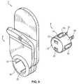
- FIG. 8is a front perspective view of the charge clip of the present invention, shown supporting a personal electronic instrument (PEI) and illustrating the connection between the PEI and the charge clip using a charge cord for charging the PEI.
- PEIpersonal electronic instrument
- FIG. 9is a front perspective exploded view of the charge clip of the present invention shown in FIGS. 1-8 .
- FIG. 10is a top plan exploded view of the charge clip of the present invention shown in FIGS. 1-9 .
- FIG. 11is a right elevational exploded view of the charge clip of the present invention shown in FIGS. 1-10 .
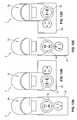
- FIGS. 12A-12Dare front plan views of the charge clip of the present invention mounted to an AC wall outlet, where the AC wall outlet is shown in four different orientations.
- FIG. 13is a rear perspective exploded view of the charge clip of the present invention shown in FIGS. 1-12 .
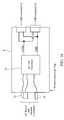
- FIG. 14is a simplified schematic/block diagram of the electrical circuit of the charge clip of the present invention.
- a charge clip 2 or station for charging a small appliance or electrical devicein particular but not limited to personal electronic instruments 4 such as cellular telephones, hand held gaming devices, digital cameras, PDAs, calculators and the like, and constructed in accordance with one form of the present invention, is preferably formed from two mateable portions, that is, a main body 6 and a power conversion plug 8 .
- the power conversion plug 8is preferably cylindrical in shape.
- the power conversion plug 8includes a circumferential side wall 10 , a front wall 12 which is preferably for aesthetic purposes convexly shaped, and a rear wall 14 which is opposite the front wall 12 .
- the rear wall 14 of the power conversion plug 8includes hot and neutral AC power prongs 16 and an AC power ground prong 18 extending outwardly therefrom so that the power conversion plug 8 may be connected directly to a socket of an AC wall outlet 20 .
- At least one, but preferably two, or more, USB ports or connectors 22are situated on the front wall 12 of the power conversion plug 8 .
- USB ports or connectors 22are situated on the front wall 12 of the power conversion plug 8 .
- the charge clip 2 of the present inventionprovides such a DC charging voltage to a selected pin on each of the USB ports or connectors 22 mounted on the power conversion plug 8 , as well as providing a ground connection to another pin on each of the USB ports or connectors 22 .
- FIG. 14A simplified schematic/block diagram of a circuit housed by the power conversion plug 8 and situated in an interior cavity defined by the cylindrical side wall 10 , front wall 12 and rear wall 14 thereof is shown in FIG. 14 .
- the power and ground prongs 16 , 18 of the power conversion plug 8are electrically connected to an AC-to-DC (AC/DC) converter circuit 24 situated within the power conversion plug 8 .
- the AC/DC converter circuit 24receives the 110 volt AC (alternating current) power provided by the wall outlet 20 to which the charge clip 2 is connected, and converts the AC voltage to a DC voltage, and in particular, a +5 volt DC voltage.
- the +5 volt DC voltageis provided to each of the USB connectors or ports 22 mounted on the front wall 12 of the power conversion plug 8 through electrical lines connected between the AC/DC converter circuit 24 and the USB connectors or ports 22 and, similarly, ground potential is provided by electrical lines connected between the AC/DC converter circuit 24 and the USB connectors or ports 22 .
- a usermay connect one or more PEIs 4 to the USB connectors or ports 22 situated on the power conversion plug 8 with a power charging cord 26 which is compatible with the USB connectors or ports 22 and the PEIs 4 being charged.
- the power conversion plug 8is received by an aperture 28 formed through the thickness of the main body 6 of the charge clip 2 , as can be seen from FIGS. 9 and 13 . As can also be seen, the power conversion plug 8 may be removed from the aperture 28 and repositioned therein in one of several different orientations.
- the power conversion plug 8includes preferably four ribs 30 extending outwardly from the outer surface of the side wall 10 , with adjacent ribs 30 being spaced apart about the circumference thereof by 90 degrees.
- the ribs 30extend at least partially over the outer surface of the side wall 10 of the power conversion plug 8 in an axial direction between the front wall 12 and the rear wall 14 thereof.
- Corresponding notches 32are formed in the rear surface 34 of the main body 6 of the charge clip 2 and which extend at least partially through the thickness thereof toward the front surface 36 of the main body 6 of the charge clip.
- the notches 32do not extend all the way through the thickness so that they are not visible on the front surface 36 of the main body 6 , which provides a more aesthetically pleasing appearance to the charge clip 2 and so that a user may push on the main body 6 of the charge clip to force the power and ground prongs 16 , 18 into a wall outlet 20 without the power conversion plug 8 moving axially within the plug receiving aperture 28 of the main body 6 .
- the ribs 30extend from the rear wall 14 of the power conversion plug 8 towards the front wall 12 , but, preferably, are recessed from the front wall 12 .
- the power conversion plug 8may be inserted into the aperture 28 of the charge clip 2 from the rear surface 34 thereof, and may be removed therefrom by pulling outwardly on the plug 8 from the rear surface 34 of the main body 6 of the charge clip 2 .
- the power conversion plug 8may be orientated in one of four positions within the aperture 28 of the main body 6 of the charge clip and, as will be explained in greater detail, this feature which allows the power conversion plug 8 to be reoriented with respect to the main body 6 of the charge clip permits the charge clip 2 to be used with AC wall outlets 20 which may have been installed in four different orientations (see FIGS. 12A-12D ).
- the main body 6 of the charge clip 2is an elongated member, preferably slightly longer than a conventional wall outlet cover plate. It includes a planar back plate 38 and a front plate 40 situated in front of the back plate 38 , the front and back plates 40 , 38 being joined together to define lateral side walls 42 , a top wall 44 and a bottom wall 46 of the main body 6 .
- a groove or channel 48is formed in the adjoining lateral side walls 42 , top wall 44 and bottom wall 46 of the main body 6 where the front and back plates 40 , 38 are joined together.
- the groove 48is provided for cord management, that is, so that excess length of the charging cord 26 connected between the USB ports or connectors 22 on the power conversion plug 8 and the PEIs 4 being charged may be conveniently wrapped about the main body 6 in the groove 48 between the front 40 plate and the back plate 38 .
- the upper portion or segment 50 of the back plate 38extends upwardly, while the upper portion or segment 52 of the front plate 40 diverges from the plane in which the back plate 38 resides at an acute angle therefrom in a direction outwardly of the front of the main body 6 .
- the widths of the front plate 40 and the back plate 38are preferably substantially the same, and so are the thicknesses.
- the upper portion 50 of the back plate 38 and the upper portion 52 of the front plate 40where the two diverge, define a cradle 54 which may receive and support one or more PEIs 4 , as shown in FIGS. 8 and 11 .
- the PEIs 4are supported by the main body 6 of the charge clip 2 in the cradle 54 when the charge clip 2 is in an upright (vertical) position.
- the cradle 54has a depth and width which are selected to receive one or more of the electrical devices 4 (e.g., cellular telephones, hand held gaming devices, PDAs, shavers or the like) and holds such electrical devices in a safe and convenient location on the charge clip 2 , as shown in the drawings.
- the electrical devices 4do not have to occupy space on the countertop or other horizontal surface when being charged and are not subjected to damage from liquid spillage and the like.
- the charge clip 2 of the present inventionis adapted to hold the portable electrical device 4 during charging, as well as providing a location for maintaining the device 4 when the device is not being used so that the device can be easily found. Furthermore, the charge clip 2 of the present invention, with its top cradle 54 , keeps the device 4 clean and out of harm's way while the device is being charged.
- the angled upper segment 52 of the front plate 40does not extend vertically as high as the upper segment 50 of the back plate 38 , as can be seen in FIG. 4 , so that any electrical device 4 held in the cradle 54 may be easily placed there or retrieved by a user from the front of the charge clip 2 .
- AC wall outlets 20may be disposed in one of four orientations, such as shown in FIGS. 12A-12D .
- a two socket AC wall outlet 20may be disposed with the ground contacts of the each socket in a bottom position (see FIG. 12A ), in a right position (see FIG. 12B ), in a top position (see FIG. 12C ) and in a left position (see FIG. 12D ).
- the charge clip 2 of the present inventionis reconfigurable by removing the power conversion plug 8 from the aperture 28 formed in the main body 6 of the charge clip, rotating the plug 8 and reinserting the plug 8 into the aperture 28 in a different orientation, with the ribs 30 being received by corresponding notches 32 formed in the main body 6 , so that the power prongs 16 and ground prong 18 on the power conversion plug 8 may be properly received by a socket of the wall outlet 20 and with the main body 6 of the charge clip 2 being oriented longitudinally in a vertical or upright position when the charge clip is plugged into a socket of the wall outlet 20 .
- the charge clip 2 of the present inventionensures that the cradle 54 is always in an upright position when the charge clip 2 is mounted on a wall outlet 20 to hold one or more PEIs 4 or other electrical devices in the cradle 54 .
- the lower portion 56 of the charge clip 2is preferably circular and has a diameter which is less than the width of the major portions of the front and back plates 40 , 38 of the main body 6 . This is to ensure that the charge clip 2 , when mounted on an AC wall outlet 20 , only occupies one electrical socket thereof and does not overlap an adjacent electrical socket of the wall outlet 20 or interfere with the use thereof independently of the charge clip 2 , as can be seen from FIGS. 12A-12D .
- the design of the cradle 54 formed in the upper portion of the charge clip 2 and, in particular, the main body 6 thereof,allows one or more PEIs 4 to be accessed from a number of directions, including the front of the charge clip, the left and right side of the charge clip and from the top (in an upward direction) of the charge clip.
- the power conversion plug 8is described herein as being preferably cylindrical in form, with ribs 30 extending from the outer surface of the cylindrical side wall 10 thereof, and the aperture 28 formed in the main body 6 of the charge clip is described as being circular, it should be understood that the power conversion plug 8 may be formed in other geometrical shapes, including rectangular, square or polygonal, with a conformingly shaped aperture 28 formed in the main body 6 of the charge clip 2 to receive the power conversion plug 8 , whereby the power conversion plug 8 may be removed from the main body 6 of the charge clip 2 , reoriented and repositioned therein so that the main body 6 of the charge clip is always oriented in an upright position, with the cradle 54 formed therein situated at the top of the charge clip 2 to support, without falling, one or more electrical devices 4 therein.
- the power conversion plug 8in a cylindrical shape, and the aperture 28 formed in the main body 6 of the charge clip in a round shape, without ribs 30 or notches 32 being formed on and in the power conversion plug 8 and main body 6 , respectively, so that the power conversion plug 8 is receivable by the aperture 28 with a frictional fit, and the main body 6 of the charge clip 2 is frictionally rotatable on the power conversion plug 8 to orient the main body 6 of the charge clip 2 in a vertically upright position thereon.
- notches 32have been described as being formed on the main body 6 about the aperture 28 , and the ribs 30 have been described as being formed on the power conversion plug 8 , it should be understood that the positions of the ribs 30 and the notches 32 may be reversed, with the ribs 30 being formed on the main body 6 to partially extend into the aperture 28 , and the notches 32 being formed in the cylindrical side wall 10 of the power conversion plug 8 .
- the width of the main body 6is preferably about that of a small sized (two socket) cover plate forming part of the AC wall outlet 20 , and the main body 6 of the charge clip 2 is preferably slightly taller than the small wall cover plate.
- the charge clip 2 of the present inventionis a two piece solution with all of the electronics for the conversion to a USB DC voltage in the power conversion plug 8 which plugs directly into an electrical socket of the wall outlet 20 .
- the main body 6 of the charge clip 2is provided to hold electrical devices 4 and is preferably formed from a plastic material, with no electronic circuitry formed therein or thereon, and it can be attached to the power conversion plug 8 in one of four orientations, ensuring that the cradle 54 for holding electronic devices 4 is always situated at the top no matter how the wall outlets 20 (and the power conversion plug 8 ) are oriented.
- This two piece solutionsolves the issues relating to having wall outlets 20 disposed in various orientations to allow the user to have a device situated in the cradle 54 and held thereby, which cradle 54 will always be in a vertical position and at the top of the charge clip 2 no matter how an electrician installed the AC wall outlets 20 .
- the groove or channel 48 formed about the side walls 42 , top wall 44 and bottom wall 46 of the charge clip 2provides cord management and allows the user to wrap thereabout excess charging cord 26 between the USB port or connector 22 on the power conversion plug 8 and the PEI 4 .
- the cradle 54may have situated therein a rubberized “taco shell” strip of material (not shown) to help secure the electronic devices therein. Additionally, it should be realized that the power conversion plug 8 may be removed from the main body 6 of the charge clip and used separately, without the main body 6 , to provide power to an electrical device 4 .
- an AC power outlet(not shown) on the front wall 12 of the power conversion plug 8 in lieu of, or in addition to, the USB connectors 22 so that, if the electrical device 4 to be charged has its own transformer forming part of the charging cord 26 , the transformer may be plugged into the AC power outlet on the plug 8 to charge the electrical device 4 rather than using the USB connector 22 .
Landscapes
- Engineering & Computer Science (AREA)
- Power Engineering (AREA)
- Microelectronics & Electronic Packaging (AREA)
- Charge And Discharge Circuits For Batteries Or The Like (AREA)
- Connector Housings Or Holding Contact Members (AREA)
Abstract
Description
Claims (8)
Priority Applications (1)
| Application Number | Priority Date | Filing Date | Title |
|---|---|---|---|
| US13/065,370US8686683B2 (en) | 2010-03-22 | 2011-03-21 | Charge clip |
Applications Claiming Priority (2)
| Application Number | Priority Date | Filing Date | Title |
|---|---|---|---|
| US34075610P | 2010-03-22 | 2010-03-22 | |
| US13/065,370US8686683B2 (en) | 2010-03-22 | 2011-03-21 | Charge clip |
Publications (2)
| Publication Number | Publication Date |
|---|---|
| US20110227535A1 US20110227535A1 (en) | 2011-09-22 |
| US8686683B2true US8686683B2 (en) | 2014-04-01 |
Family
ID=44646688
Family Applications (1)
| Application Number | Title | Priority Date | Filing Date |
|---|---|---|---|
| US13/065,370Active - Reinstated2031-10-16US8686683B2 (en) | 2010-03-22 | 2011-03-21 | Charge clip |
Country Status (1)
| Country | Link |
|---|---|
| US (1) | US8686683B2 (en) |
Cited By (38)
| Publication number | Priority date | Publication date | Assignee | Title |
|---|---|---|---|---|
| US20140370743A1 (en)* | 2013-06-13 | 2014-12-18 | Jim Maesnor | External Power Supply |
| US9054472B2 (en)* | 2013-04-02 | 2015-06-09 | Hon Hai Precision Industry Co., Ltd. | Power adapter with plug member stowable in housing |
| US9148030B1 (en)* | 2014-04-21 | 2015-09-29 | Douglas S. Johnson | Support for a battery charger and battery charger electrical cable |
| WO2016003585A1 (en)* | 2014-06-29 | 2016-01-07 | Warren William J | Electrical charging devices and assemblies |
| EP3051781A1 (en) | 2015-01-29 | 2016-08-03 | "Durable" Hunke & Jochheim GmbH & Co. KG | Clamping device |
| US9437983B2 (en)* | 2015-01-26 | 2016-09-06 | Progressive Industries, Inc. | Electrical connection box |
| DE102015212566A1 (en) | 2015-07-06 | 2017-01-12 | Eifelgrün Gmbh | HOUSING FOR A CONNECTOR POWER SUPPLY |
| US9627802B2 (en) | 2014-06-29 | 2017-04-18 | William J. Warren | Electrical charging devices and assemblies |
| US9660379B1 (en)* | 2016-05-18 | 2017-05-23 | Ford Global Technologies, Llc | Vehicle electrical connector assembly and connection method |
| US9793729B2 (en)* | 2015-01-05 | 2017-10-17 | Schneider Electric It Corporation | Uninterruptible power supply having removable battery |
| US9853384B2 (en)* | 2014-02-27 | 2017-12-26 | Ran Azoulay | Socket apparatus |
| US9899767B1 (en)* | 2016-12-28 | 2018-02-20 | Eaton Corporation | Connector with clockable integrated power switching |
| US9997882B1 (en)* | 2017-02-27 | 2018-06-12 | William J. Warren | Electrical charging devices and assemblies |
| US10027149B2 (en) | 2014-06-29 | 2018-07-17 | William J. Warren | Electrical charging device chassis and cases |
| US10050397B1 (en)* | 2017-06-26 | 2018-08-14 | Daniel Hetzroni | Mount for a touch-screen device |
| US10063088B2 (en) | 2014-06-29 | 2018-08-28 | William J. Warren | Computing device inductive charging cases and methods of use |
| US20180248321A1 (en)* | 2017-02-27 | 2018-08-30 | William J. Warren | Electrical Charging Devices with Bar Stabilizers and Assemblies |
| US20180269640A1 (en)* | 2016-10-31 | 2018-09-20 | Leroy Walker | Universal multi-charger device |
| US10153649B2 (en) | 2014-06-29 | 2018-12-11 | William J. Warren | Computing device charging cases and methods of use |
| US10177584B2 (en) | 2017-02-27 | 2019-01-08 | William J. Warren | Electrical charging devices and assemblies |
| US10355501B2 (en) | 2017-10-11 | 2019-07-16 | William J. Warren | Electrical charging devices with resilient actuation |
| USD864874S1 (en)* | 2018-01-30 | 2019-10-29 | Guangdong Bestek E-Commerce Co., Ltd. | Power strip |
| US10608449B2 (en) | 2017-02-27 | 2020-03-31 | William J. Warren | Electrical charging devices with translating stabilizers |
| USD886733S1 (en) | 2017-04-11 | 2020-06-09 | William J. Warren | Charger |
| USD892725S1 (en)* | 2014-12-31 | 2020-08-11 | Chargepoint, Inc. | Electric vehicle charging station |
| US10826200B2 (en)* | 2017-04-04 | 2020-11-03 | Sh Korea Co., Ltd. | Power connector dedicated to heating film |
| US10916898B2 (en)* | 2016-03-22 | 2021-02-09 | Koninklijke Philips N.V. | Safety switch arrangement for a personal care appliance |
| USD918841S1 (en)* | 2018-03-16 | 2021-05-11 | Lifeworks Technology Group LLC | Electrical power extension |
| USD932442S1 (en) | 2020-10-15 | 2021-10-05 | E. Mishan & Sons, Inc. | Surge protector |
| US20210336383A1 (en)* | 2020-04-22 | 2021-10-28 | Shenzhen Chenbei Technology Co., Ltd. | Mounting bracket and electronic device |
| USD939932S1 (en) | 2014-11-20 | 2022-01-04 | Snaprays, Llc | Wall plate |
| USD943517S1 (en) | 2021-03-25 | 2022-02-15 | E. Mishan & Sons, Inc. | Wall charger |
| USD947775S1 (en) | 2021-05-03 | 2022-04-05 | E. Mishan & Sons, Inc. | Wall charger |
| WO2023075827A1 (en)* | 2021-10-25 | 2023-05-04 | Auraglow Llc | Electric toothbrush and charging dock |
| USD998345S1 (en) | 2021-10-25 | 2023-09-12 | Auraglow Llc | Electric toothbrush and charging dock |
| USD1005241S1 (en)* | 2022-04-29 | 2023-11-21 | Ontel Products Corporation | Duplex wall plug housing |
| USD1042353S1 (en)* | 2022-04-25 | 2024-09-17 | Ontel Products Corporation | Wall plug housing |
| USD1065837S1 (en) | 2022-04-07 | 2025-03-11 | Auraglow Llc | Charging dock |
Families Citing this family (18)
| Publication number | Priority date | Publication date | Assignee | Title |
|---|---|---|---|---|
| TW201134200A (en)* | 2010-03-30 | 2011-10-01 | Hon Hai Prec Ind Co Ltd | Digital camera |
| US8712486B2 (en)* | 2011-01-12 | 2014-04-29 | Yeoshua Sorias | Detachably integrated battery charger for mobile cell phones and like devices |
| US8579641B1 (en) | 2011-03-14 | 2013-11-12 | Google Inc. | Multi-orientation plug |
| US8398430B1 (en) | 2011-03-14 | 2013-03-19 | Google Inc. | Multi-orientation plug |
| USD720287S1 (en) | 2011-08-30 | 2014-12-30 | Perumala Corporation | Charge interrupting device |
| US8598850B2 (en) | 2011-08-30 | 2013-12-03 | Perumala Corporation | Devices and methods for optimizing rechargeable battery life |
| DE102012003197B4 (en)* | 2012-02-17 | 2014-06-05 | Ecobility Gmbh | socket |
| US9391412B2 (en)* | 2013-06-14 | 2016-07-12 | Enviragen Llc | 12 volt electrical outlet assembly and method of installing the same |
| US9337676B2 (en)* | 2014-01-07 | 2016-05-10 | Joseph Benigno | Outlet enclosure for device chargers |
| US10363182B2 (en) | 2014-07-14 | 2019-07-30 | Hill-Rom Services, Inc. | Patient control arm with phone dock and head of bed lockout |
| US9438052B1 (en)* | 2015-03-27 | 2016-09-06 | Ellen Louise Cole | Mobile device holder-charger |
| US10355424B2 (en)* | 2017-05-28 | 2019-07-16 | Samuel Messinger | Electronic device holder |
| US9979805B1 (en)* | 2017-06-02 | 2018-05-22 | Cheng Yu Huang | Multi-functional apparatus for mobile phone and tablet computer |
| US10522959B2 (en)* | 2017-09-18 | 2019-12-31 | Samuel Messinger | System and method for metered public electrical wall charger |
| EP3493098A1 (en)* | 2017-11-30 | 2019-06-05 | ELATEC GmbH | Rfid reader with turnable usb connector |
| USD937770S1 (en) | 2019-11-25 | 2021-12-07 | Amazon Technologies, Inc. | Charging clip |
| US12046933B2 (en)* | 2021-03-09 | 2024-07-23 | Yuyi Lee | Power solution cradle dock |
| US20230187951A1 (en)* | 2021-10-25 | 2023-06-15 | Auraglow Llc | Electric toothbrush and charging dock |
Citations (71)
| Publication number | Priority date | Publication date | Assignee | Title |
|---|---|---|---|---|
| US2636096A (en) | 1951-05-09 | 1953-04-21 | Blasi Frank Di | Fused circuit plug-in receptacle |
| US4960384A (en) | 1989-09-18 | 1990-10-02 | Silicon Graphics Inc. | Retaining means for removable computer drive and release means for same |
| USD312615S (en) | 1988-10-07 | 1990-12-04 | Cable Electric Products, Inc. | Surge protector housing |
| USD316484S (en) | 1988-10-28 | 1991-04-30 | Times Three Pty. Limited | Diver's belt catch bag hook |
| US5313152A (en) | 1992-06-19 | 1994-05-17 | Ford Motor Company | Network for minimizing current imbalances in a faradaic battery |
| US5327065A (en) | 1992-01-22 | 1994-07-05 | Hughes Aircraft Company | Hand-held inductive charger having concentric windings |
| USD348775S (en) | 1991-09-27 | 1994-07-19 | Motorola, Inc. | Belt clip for a radio pager |
| USD350938S (en) | 1993-03-12 | 1994-09-27 | Curtis Manufacturing Company, Inc. | Multiple outlet surge protector |
| USD357460S (en) | 1993-06-25 | 1995-04-18 | Lovett Robert H | Outlet for multiple electrical receptacles |
| USD361315S (en) | 1993-10-14 | 1995-08-15 | Thomas & Betts Corporation | Electrical surge suppressor |
| USD379160S (en) | 1995-08-09 | 1997-05-13 | Minnesota Mining And Manufacturing Company | Buckle |
| USD401219S (en) | 1996-12-05 | 1998-11-17 | All-Line Inc. | Socket |
| USD408355S (en) | 1998-01-26 | 1999-04-20 | Steelcase Inc. | Power and data interface module |
| US5955791A (en) | 1997-04-14 | 1999-09-21 | Irlander; James E. | Master/slave circuit for dust collector |
| USD415067S (en) | 1998-08-13 | 1999-10-12 | Chin Tung | Hook for fastening belt device |
| USD428327S (en) | 1999-11-19 | 2000-07-18 | All-Line Inc. | Cord reel |
| USD432499S (en) | 2000-02-14 | 2000-10-24 | All-Line Inc. | Power strip |
| USD434344S (en) | 1999-04-15 | 2000-11-28 | Nifco Inc. | Buckle |
| USD440203S1 (en) | 2000-02-17 | 2001-04-10 | Belkin Components | Multiple outlet adapter |
| USD442550S1 (en) | 2000-05-17 | 2001-05-22 | Belkin Components | Multiple outlet wall tap |
| USD447087S1 (en) | 2000-06-15 | 2001-08-28 | Shirley J. Hodge | Hat holder |
| USD461746S1 (en) | 2000-11-07 | 2002-08-20 | Specialty Coating Systems, Inc. | Belt clip |
| USD468848S1 (en) | 2002-05-16 | 2003-01-14 | American Tack & Hardware Co., Ltd. | Night light with convenience outlets |
| USD469062S1 (en) | 2002-01-07 | 2003-01-21 | Nieto German | Electrical connector |
| US6510067B1 (en) | 2000-11-03 | 2003-01-21 | Cisco Technology, Inc. | System, method and apparatus for protecting consumer electronic devices from brownouts and short duration power outages |
| USD477792S1 (en) | 2000-04-21 | 2003-07-29 | Ykk Corporation | Fastening device for clothing |
| US6614206B1 (en) | 2002-05-23 | 2003-09-02 | Palm, Inc. | Universal USB charging accessory |
| USD481357S1 (en) | 2002-10-21 | 2003-10-28 | All-Line Inc. | Power strip |
| USD483724S1 (en) | 2003-03-11 | 2003-12-16 | Exito Electronics, Ltd. | Outlet portion of an electrical power cord |
| USD486126S1 (en) | 2003-04-01 | 2004-02-03 | Tower Manufacturing Corporation | GFCI with five receptacles |
| US20040121648A1 (en) | 2002-07-26 | 2004-06-24 | V-Squared Networks | Network device for communicating information |
| USD495657S1 (en) | 2003-04-02 | 2004-09-07 | Multiway Industries Ltd | Electrical plug |
| US6821134B2 (en)* | 2001-09-04 | 2004-11-23 | Delta Electronics Inc. | Rotatable plug applied in power supply apparatus |
| US20050041827A1 (en)* | 2003-08-18 | 2005-02-24 | Wu Chih Hsien | Rechargeable hearing aid |
| USD514067S1 (en) | 2004-09-15 | 2006-01-31 | Multiway Industries, Ltd. | Multiple outlet wall tap |
| US7050285B2 (en) | 2003-06-04 | 2006-05-23 | Illinois Tool Works Inc. | Surge protector assembly with ground-connector status indicator circuitry |
| US7140922B2 (en) | 2002-12-19 | 2006-11-28 | Pacusma Company, Ltd. | Multi-outlet AC/DC adapter |
| US20070108938A1 (en) | 2003-06-11 | 2007-05-17 | Dusan Veselic | Universal serial bus charger for a mobile device |
| US20070273325A1 (en) | 2006-02-24 | 2007-11-29 | Black & Decker Inc. | Power station with built in battery charger |
| US20070285053A1 (en) | 2006-06-12 | 2007-12-13 | Teledex, Inc. | Portable charger |
| US20080012536A1 (en) | 2006-07-11 | 2008-01-17 | Glass Bruce A | Charging station for portable electronic instruments |
| USD567708S1 (en) | 2007-09-13 | 2008-04-29 | David Edwin Jallen | Buckless clothing belt hook |
| USD568785S1 (en) | 2006-08-28 | 2008-05-13 | Universal Trim Supply Co., Ltd. | Woven tape adjusting fastener |
| US20080111522A1 (en) | 2006-11-15 | 2008-05-15 | Motorola, Inc. | Method and system for charging electronic devices |
| US20080140887A1 (en) | 2006-12-08 | 2008-06-12 | Nokia Corporation | Enhanced communication via a serial interface |
| US20080150480A1 (en)* | 2006-10-13 | 2008-06-26 | Amir Navid | Video game controller charging system |
| US20080157715A1 (en) | 2006-01-07 | 2008-07-03 | Egate-International Gmbh | Plug-type charger for small electrical device |
| US20080164845A1 (en) | 2007-01-05 | 2008-07-10 | Thomas Choi | Removable and Replaceable Docking Unit |
| US20080174265A1 (en)* | 2006-09-05 | 2008-07-24 | Sanyo Electric Co., Ltd. | Battery charger |
| US20080183909A1 (en) | 2007-01-25 | 2008-07-31 | Samsung Electronics Co., Ltd. | Apparatus and method for controlling usb operation |
| US20080231233A1 (en) | 2001-12-03 | 2008-09-25 | Walter Thornton | Power converter including auxiliary battery charger |
| USD582346S1 (en) | 2008-02-01 | 2008-12-09 | Mig Electronic Industrial Co., Ltd. | Six-hole power splitter |
| US20090015198A1 (en)* | 2007-07-09 | 2009-01-15 | Marware, Inc. | Docking and charging station and method for a portable electronic device |
| USD586691S1 (en) | 2008-02-23 | 2009-02-17 | John T Snell | Belt clip |
| USD588065S1 (en) | 2008-03-07 | 2009-03-10 | Belkin International, Inc. | Electric power adapter |
| US7520783B2 (en) | 2005-08-05 | 2009-04-21 | Powertech Industrial Co., Ltd. | Energy saving outlet having a sensor and method of use thereof |
| US20090284219A1 (en) | 2008-05-14 | 2009-11-19 | Meek Ronald L | Little Power House Emergency Power System |
| USD606545S1 (en) | 2009-01-06 | 2009-12-22 | Steven Kenneth Salmon | Docking station |
| USD616817S1 (en) | 2009-04-08 | 2010-06-01 | Strenumed, Inc. | Battery charger adapter |
| USD618175S1 (en) | 2009-10-15 | 2010-06-22 | Multiway Industries (Hk) Ltd. | Three-outlet surge-protected adaptor |
| USD619535S1 (en) | 2009-10-15 | 2010-07-13 | Multiway Industries (Hk) Ltd. | Five-outlet surge-protected adaptor |
| US20100219790A1 (en) | 2009-02-27 | 2010-09-02 | Fairchild Semiconductor Corporation | Peripheral device host charging |
| US7824051B2 (en) | 2005-01-06 | 2010-11-02 | S.C. Johnson & Son, Inc. | Color changing light object and user interface for same |
| US20110016334A1 (en) | 2009-07-20 | 2011-01-20 | Texas Instruments Incorporated | Auto-Detect Polling for Correct Handshake to USB Client |
| US20110029703A1 (en) | 2009-07-29 | 2011-02-03 | Hong Fu Jin Precision Industry (Shenzhen) Co., Ltd | Electronic device capable of automatically switching between a master mode and a slave mode |
| US20110050164A1 (en) | 2008-05-07 | 2011-03-03 | Afshin Partovi | System and methods for inductive charging, and improvements and uses thereof |
| US20110084660A1 (en) | 2009-10-08 | 2011-04-14 | Scosche Industries, Inc. | Wall charger with removable charger |
| US7997925B2 (en) | 2007-06-08 | 2011-08-16 | Chung Man Lam | Multifunctional wall socket |
| US20110276734A1 (en) | 2009-11-03 | 2011-11-10 | Kenneth Helfrich | USB Dedicated Charger Identification Circuit |
| US8072183B2 (en) | 2009-03-12 | 2011-12-06 | Griffin Technology, Inc. | Multiple interface device charger with removable battery pack |
| US20120258632A1 (en) | 2011-04-08 | 2012-10-11 | Powertech Industrial Co., Ltd. | Thin socket |
Family Cites Families (1)
| Publication number | Priority date | Publication date | Assignee | Title |
|---|---|---|---|---|
| US8959500B2 (en)* | 2006-12-11 | 2015-02-17 | Nytell Software LLC | Pipelined processor and compiler/scheduler for variable number branch delay slots |
- 2011
- 2011-03-21USUS13/065,370patent/US8686683B2/enactiveActive - Reinstated
Patent Citations (71)
| Publication number | Priority date | Publication date | Assignee | Title |
|---|---|---|---|---|
| US2636096A (en) | 1951-05-09 | 1953-04-21 | Blasi Frank Di | Fused circuit plug-in receptacle |
| USD312615S (en) | 1988-10-07 | 1990-12-04 | Cable Electric Products, Inc. | Surge protector housing |
| USD316484S (en) | 1988-10-28 | 1991-04-30 | Times Three Pty. Limited | Diver's belt catch bag hook |
| US4960384A (en) | 1989-09-18 | 1990-10-02 | Silicon Graphics Inc. | Retaining means for removable computer drive and release means for same |
| USD348775S (en) | 1991-09-27 | 1994-07-19 | Motorola, Inc. | Belt clip for a radio pager |
| US5327065A (en) | 1992-01-22 | 1994-07-05 | Hughes Aircraft Company | Hand-held inductive charger having concentric windings |
| US5313152A (en) | 1992-06-19 | 1994-05-17 | Ford Motor Company | Network for minimizing current imbalances in a faradaic battery |
| USD350938S (en) | 1993-03-12 | 1994-09-27 | Curtis Manufacturing Company, Inc. | Multiple outlet surge protector |
| USD357460S (en) | 1993-06-25 | 1995-04-18 | Lovett Robert H | Outlet for multiple electrical receptacles |
| USD361315S (en) | 1993-10-14 | 1995-08-15 | Thomas & Betts Corporation | Electrical surge suppressor |
| USD379160S (en) | 1995-08-09 | 1997-05-13 | Minnesota Mining And Manufacturing Company | Buckle |
| USD401219S (en) | 1996-12-05 | 1998-11-17 | All-Line Inc. | Socket |
| US5955791A (en) | 1997-04-14 | 1999-09-21 | Irlander; James E. | Master/slave circuit for dust collector |
| USD408355S (en) | 1998-01-26 | 1999-04-20 | Steelcase Inc. | Power and data interface module |
| USD415067S (en) | 1998-08-13 | 1999-10-12 | Chin Tung | Hook for fastening belt device |
| USD434344S (en) | 1999-04-15 | 2000-11-28 | Nifco Inc. | Buckle |
| USD428327S (en) | 1999-11-19 | 2000-07-18 | All-Line Inc. | Cord reel |
| USD432499S (en) | 2000-02-14 | 2000-10-24 | All-Line Inc. | Power strip |
| USD440203S1 (en) | 2000-02-17 | 2001-04-10 | Belkin Components | Multiple outlet adapter |
| USD477792S1 (en) | 2000-04-21 | 2003-07-29 | Ykk Corporation | Fastening device for clothing |
| USD442550S1 (en) | 2000-05-17 | 2001-05-22 | Belkin Components | Multiple outlet wall tap |
| USD447087S1 (en) | 2000-06-15 | 2001-08-28 | Shirley J. Hodge | Hat holder |
| US6510067B1 (en) | 2000-11-03 | 2003-01-21 | Cisco Technology, Inc. | System, method and apparatus for protecting consumer electronic devices from brownouts and short duration power outages |
| USD461746S1 (en) | 2000-11-07 | 2002-08-20 | Specialty Coating Systems, Inc. | Belt clip |
| US6821134B2 (en)* | 2001-09-04 | 2004-11-23 | Delta Electronics Inc. | Rotatable plug applied in power supply apparatus |
| US20080231233A1 (en) | 2001-12-03 | 2008-09-25 | Walter Thornton | Power converter including auxiliary battery charger |
| USD469062S1 (en) | 2002-01-07 | 2003-01-21 | Nieto German | Electrical connector |
| USD468848S1 (en) | 2002-05-16 | 2003-01-14 | American Tack & Hardware Co., Ltd. | Night light with convenience outlets |
| US6614206B1 (en) | 2002-05-23 | 2003-09-02 | Palm, Inc. | Universal USB charging accessory |
| US20040121648A1 (en) | 2002-07-26 | 2004-06-24 | V-Squared Networks | Network device for communicating information |
| USD481357S1 (en) | 2002-10-21 | 2003-10-28 | All-Line Inc. | Power strip |
| US7140922B2 (en) | 2002-12-19 | 2006-11-28 | Pacusma Company, Ltd. | Multi-outlet AC/DC adapter |
| USD483724S1 (en) | 2003-03-11 | 2003-12-16 | Exito Electronics, Ltd. | Outlet portion of an electrical power cord |
| USD486126S1 (en) | 2003-04-01 | 2004-02-03 | Tower Manufacturing Corporation | GFCI with five receptacles |
| USD495657S1 (en) | 2003-04-02 | 2004-09-07 | Multiway Industries Ltd | Electrical plug |
| US7050285B2 (en) | 2003-06-04 | 2006-05-23 | Illinois Tool Works Inc. | Surge protector assembly with ground-connector status indicator circuitry |
| US20070108938A1 (en) | 2003-06-11 | 2007-05-17 | Dusan Veselic | Universal serial bus charger for a mobile device |
| US20050041827A1 (en)* | 2003-08-18 | 2005-02-24 | Wu Chih Hsien | Rechargeable hearing aid |
| USD514067S1 (en) | 2004-09-15 | 2006-01-31 | Multiway Industries, Ltd. | Multiple outlet wall tap |
| US7824051B2 (en) | 2005-01-06 | 2010-11-02 | S.C. Johnson & Son, Inc. | Color changing light object and user interface for same |
| US7520783B2 (en) | 2005-08-05 | 2009-04-21 | Powertech Industrial Co., Ltd. | Energy saving outlet having a sensor and method of use thereof |
| US20080157715A1 (en) | 2006-01-07 | 2008-07-03 | Egate-International Gmbh | Plug-type charger for small electrical device |
| US20070273325A1 (en) | 2006-02-24 | 2007-11-29 | Black & Decker Inc. | Power station with built in battery charger |
| US20070285053A1 (en) | 2006-06-12 | 2007-12-13 | Teledex, Inc. | Portable charger |
| US20080012536A1 (en) | 2006-07-11 | 2008-01-17 | Glass Bruce A | Charging station for portable electronic instruments |
| USD568785S1 (en) | 2006-08-28 | 2008-05-13 | Universal Trim Supply Co., Ltd. | Woven tape adjusting fastener |
| US20080174265A1 (en)* | 2006-09-05 | 2008-07-24 | Sanyo Electric Co., Ltd. | Battery charger |
| US20080150480A1 (en)* | 2006-10-13 | 2008-06-26 | Amir Navid | Video game controller charging system |
| US20080111522A1 (en) | 2006-11-15 | 2008-05-15 | Motorola, Inc. | Method and system for charging electronic devices |
| US20080140887A1 (en) | 2006-12-08 | 2008-06-12 | Nokia Corporation | Enhanced communication via a serial interface |
| US20080164845A1 (en) | 2007-01-05 | 2008-07-10 | Thomas Choi | Removable and Replaceable Docking Unit |
| US20080183909A1 (en) | 2007-01-25 | 2008-07-31 | Samsung Electronics Co., Ltd. | Apparatus and method for controlling usb operation |
| US7997925B2 (en) | 2007-06-08 | 2011-08-16 | Chung Man Lam | Multifunctional wall socket |
| US20090015198A1 (en)* | 2007-07-09 | 2009-01-15 | Marware, Inc. | Docking and charging station and method for a portable electronic device |
| USD567708S1 (en) | 2007-09-13 | 2008-04-29 | David Edwin Jallen | Buckless clothing belt hook |
| USD582346S1 (en) | 2008-02-01 | 2008-12-09 | Mig Electronic Industrial Co., Ltd. | Six-hole power splitter |
| USD586691S1 (en) | 2008-02-23 | 2009-02-17 | John T Snell | Belt clip |
| USD588065S1 (en) | 2008-03-07 | 2009-03-10 | Belkin International, Inc. | Electric power adapter |
| US20110050164A1 (en) | 2008-05-07 | 2011-03-03 | Afshin Partovi | System and methods for inductive charging, and improvements and uses thereof |
| US20090284219A1 (en) | 2008-05-14 | 2009-11-19 | Meek Ronald L | Little Power House Emergency Power System |
| USD606545S1 (en) | 2009-01-06 | 2009-12-22 | Steven Kenneth Salmon | Docking station |
| US20100219790A1 (en) | 2009-02-27 | 2010-09-02 | Fairchild Semiconductor Corporation | Peripheral device host charging |
| US8072183B2 (en) | 2009-03-12 | 2011-12-06 | Griffin Technology, Inc. | Multiple interface device charger with removable battery pack |
| USD616817S1 (en) | 2009-04-08 | 2010-06-01 | Strenumed, Inc. | Battery charger adapter |
| US20110016334A1 (en) | 2009-07-20 | 2011-01-20 | Texas Instruments Incorporated | Auto-Detect Polling for Correct Handshake to USB Client |
| US20110029703A1 (en) | 2009-07-29 | 2011-02-03 | Hong Fu Jin Precision Industry (Shenzhen) Co., Ltd | Electronic device capable of automatically switching between a master mode and a slave mode |
| US20110084660A1 (en) | 2009-10-08 | 2011-04-14 | Scosche Industries, Inc. | Wall charger with removable charger |
| USD619535S1 (en) | 2009-10-15 | 2010-07-13 | Multiway Industries (Hk) Ltd. | Five-outlet surge-protected adaptor |
| USD618175S1 (en) | 2009-10-15 | 2010-06-22 | Multiway Industries (Hk) Ltd. | Three-outlet surge-protected adaptor |
| US20110276734A1 (en) | 2009-11-03 | 2011-11-10 | Kenneth Helfrich | USB Dedicated Charger Identification Circuit |
| US20120258632A1 (en) | 2011-04-08 | 2012-10-11 | Powertech Industrial Co., Ltd. | Thin socket |
Cited By (44)
| Publication number | Priority date | Publication date | Assignee | Title |
|---|---|---|---|---|
| US9054472B2 (en)* | 2013-04-02 | 2015-06-09 | Hon Hai Precision Industry Co., Ltd. | Power adapter with plug member stowable in housing |
| US20140370743A1 (en)* | 2013-06-13 | 2014-12-18 | Jim Maesnor | External Power Supply |
| US9853384B2 (en)* | 2014-02-27 | 2017-12-26 | Ran Azoulay | Socket apparatus |
| US9148030B1 (en)* | 2014-04-21 | 2015-09-29 | Douglas S. Johnson | Support for a battery charger and battery charger electrical cable |
| US9627802B2 (en) | 2014-06-29 | 2017-04-18 | William J. Warren | Electrical charging devices and assemblies |
| US10153649B2 (en) | 2014-06-29 | 2018-12-11 | William J. Warren | Computing device charging cases and methods of use |
| US9620911B2 (en) | 2014-06-29 | 2017-04-11 | William J. Warren | Electrical charging devices and assemblies |
| US10027149B2 (en) | 2014-06-29 | 2018-07-17 | William J. Warren | Electrical charging device chassis and cases |
| US10063088B2 (en) | 2014-06-29 | 2018-08-28 | William J. Warren | Computing device inductive charging cases and methods of use |
| WO2016003585A1 (en)* | 2014-06-29 | 2016-01-07 | Warren William J | Electrical charging devices and assemblies |
| USD939932S1 (en) | 2014-11-20 | 2022-01-04 | Snaprays, Llc | Wall plate |
| USD892725S1 (en)* | 2014-12-31 | 2020-08-11 | Chargepoint, Inc. | Electric vehicle charging station |
| US9793729B2 (en)* | 2015-01-05 | 2017-10-17 | Schneider Electric It Corporation | Uninterruptible power supply having removable battery |
| US9437983B2 (en)* | 2015-01-26 | 2016-09-06 | Progressive Industries, Inc. | Electrical connection box |
| DE102015101347A1 (en)* | 2015-01-29 | 2016-08-04 | "Durable" Hunke & Jochheim Gmbh & Co. Kommanditgesellschaft | holder |
| EP3051781A1 (en) | 2015-01-29 | 2016-08-03 | "Durable" Hunke & Jochheim GmbH & Co. KG | Clamping device |
| DE102015212566A1 (en) | 2015-07-06 | 2017-01-12 | Eifelgrün Gmbh | HOUSING FOR A CONNECTOR POWER SUPPLY |
| US10916898B2 (en)* | 2016-03-22 | 2021-02-09 | Koninklijke Philips N.V. | Safety switch arrangement for a personal care appliance |
| US9660379B1 (en)* | 2016-05-18 | 2017-05-23 | Ford Global Technologies, Llc | Vehicle electrical connector assembly and connection method |
| US20180269640A1 (en)* | 2016-10-31 | 2018-09-20 | Leroy Walker | Universal multi-charger device |
| US10355435B2 (en)* | 2016-10-31 | 2019-07-16 | Leroy Walker | Universal multi-charger device |
| US9899767B1 (en)* | 2016-12-28 | 2018-02-20 | Eaton Corporation | Connector with clockable integrated power switching |
| US9997882B1 (en)* | 2017-02-27 | 2018-06-12 | William J. Warren | Electrical charging devices and assemblies |
| US10177584B2 (en) | 2017-02-27 | 2019-01-08 | William J. Warren | Electrical charging devices and assemblies |
| US20180248321A1 (en)* | 2017-02-27 | 2018-08-30 | William J. Warren | Electrical Charging Devices with Bar Stabilizers and Assemblies |
| US10608449B2 (en) | 2017-02-27 | 2020-03-31 | William J. Warren | Electrical charging devices with translating stabilizers |
| US10608384B2 (en)* | 2017-02-27 | 2020-03-31 | William J. Warren | Electrical charging devices with bar stabilizers and assemblies |
| US10826200B2 (en)* | 2017-04-04 | 2020-11-03 | Sh Korea Co., Ltd. | Power connector dedicated to heating film |
| USD886733S1 (en) | 2017-04-11 | 2020-06-09 | William J. Warren | Charger |
| US10050397B1 (en)* | 2017-06-26 | 2018-08-14 | Daniel Hetzroni | Mount for a touch-screen device |
| US10355501B2 (en) | 2017-10-11 | 2019-07-16 | William J. Warren | Electrical charging devices with resilient actuation |
| USD864874S1 (en)* | 2018-01-30 | 2019-10-29 | Guangdong Bestek E-Commerce Co., Ltd. | Power strip |
| USD918841S1 (en)* | 2018-03-16 | 2021-05-11 | Lifeworks Technology Group LLC | Electrical power extension |
| US11682858B2 (en)* | 2020-04-22 | 2023-06-20 | Shenzhen Chenbei Technology Co., Ltd. | Mounting bracket and electronic device |
| US20210336383A1 (en)* | 2020-04-22 | 2021-10-28 | Shenzhen Chenbei Technology Co., Ltd. | Mounting bracket and electronic device |
| USD932442S1 (en) | 2020-10-15 | 2021-10-05 | E. Mishan & Sons, Inc. | Surge protector |
| USD943517S1 (en) | 2021-03-25 | 2022-02-15 | E. Mishan & Sons, Inc. | Wall charger |
| USD947775S1 (en) | 2021-05-03 | 2022-04-05 | E. Mishan & Sons, Inc. | Wall charger |
| WO2023075827A1 (en)* | 2021-10-25 | 2023-05-04 | Auraglow Llc | Electric toothbrush and charging dock |
| USD998345S1 (en) | 2021-10-25 | 2023-09-12 | Auraglow Llc | Electric toothbrush and charging dock |
| USD999533S1 (en) | 2021-10-25 | 2023-09-26 | Auraglow Llc | Charging dock for an electric toothbrush |
| USD1065837S1 (en) | 2022-04-07 | 2025-03-11 | Auraglow Llc | Charging dock |
| USD1042353S1 (en)* | 2022-04-25 | 2024-09-17 | Ontel Products Corporation | Wall plug housing |
| USD1005241S1 (en)* | 2022-04-29 | 2023-11-21 | Ontel Products Corporation | Duplex wall plug housing |
Also Published As
| Publication number | Publication date |
|---|---|
| US20110227535A1 (en) | 2011-09-22 |
Similar Documents
| Publication | Publication Date | Title |
|---|---|---|
| US8686683B2 (en) | Charge clip | |
| US11190035B2 (en) | Device for charging portable electronic devices | |
| US9074761B2 (en) | Composite table lighting structure for wired charging and wireless charging | |
| TWI539702B (en) | Wall socket with connecting module | |
| US20120098493A1 (en) | Charging station | |
| US20110084651A1 (en) | Charging station | |
| US7553174B2 (en) | Cable management device configured to support one or more electrical devices and methods of manufacturing and using the same | |
| US20120169272A1 (en) | Portable usb mini-charger device | |
| US9859670B1 (en) | Rotatable universal socket | |
| US10084300B1 (en) | Integrated electrical outlet cover and support for voice-controlled assistants, speakers, and other electronic devices | |
| US10355424B2 (en) | Electronic device holder | |
| US10250050B1 (en) | Electric power charger with edge outlet | |
| US9666980B2 (en) | Electrical power strip housing | |
| CN104659623B (en) | wall plug adapter | |
| JP3200326U (en) | Power supply base for supplying various types of power | |
| CN204315861U (en) | Electrical installations with movable connection modules | |
| CN213660808U (en) | Multipurpose wireless charging socket | |
| KR101555177B1 (en) | Mobile Phone Holder | |
| KR101432744B1 (en) | Charging device set | |
| AU2007221798B2 (en) | Cable management device configured to support one or more electrical devices and methods of manufacturing and using the same | |
| TWM497847U (en) | Electrical devices having movable connecting module | |
| CN218415270U (en) | Extension socket device | |
| TW201626665A (en) | Electrical power expansion device | |
| CN203660219U (en) | Mobile phone patch cord | |
| CN103779755B (en) | Socket with rotary plug structure |
Legal Events
| Date | Code | Title | Description |
|---|---|---|---|
| AS | Assignment | Owner name:AUDIOVOX CORPORATION, NEW YORK Free format text:ASSIGNMENT OF ASSIGNORS INTEREST;ASSIGNORS:CASKEY, HENRY DALE;BENEDETTI, DAVID ANTHONY;REEL/FRAME:026324/0932 Effective date:20110506 | |
| AS | Assignment | Owner name:WELLS FAGO BANK, NATIONAL ASSOCIATION, NORTH CAROL Free format text:SECURITY AGREEMENT;ASSIGNOR:VOXX INTERNATIONAL CORPORATION;REEL/FRAME:027890/0319 Effective date:20120314 | |
| STCF | Information on status: patent grant | Free format text:PATENTED CASE | |
| MAFP | Maintenance fee payment | Free format text:PAYMENT OF MAINTENANCE FEE, 4TH YEAR, LARGE ENTITY (ORIGINAL EVENT CODE: M1551) Year of fee payment:4 | |
| FEPP | Fee payment procedure | Free format text:MAINTENANCE FEE REMINDER MAILED (ORIGINAL EVENT CODE: REM.); ENTITY STATUS OF PATENT OWNER: LARGE ENTITY | |
| LAPS | Lapse for failure to pay maintenance fees | Free format text:PATENT EXPIRED FOR FAILURE TO PAY MAINTENANCE FEES (ORIGINAL EVENT CODE: EXP.); ENTITY STATUS OF PATENT OWNER: LARGE ENTITY | |
| STCH | Information on status: patent discontinuation | Free format text:PATENT EXPIRED DUE TO NONPAYMENT OF MAINTENANCE FEES UNDER 37 CFR 1.362 | |
| FP | Lapsed due to failure to pay maintenance fee | Effective date:20220401 | |
| PRDP | Patent reinstated due to the acceptance of a late maintenance fee | Effective date:20220620 | |
| FEPP | Fee payment procedure | Free format text:PETITION RELATED TO MAINTENANCE FEES FILED (ORIGINAL EVENT CODE: PMFP); ENTITY STATUS OF PATENT OWNER: LARGE ENTITY Free format text:PETITION RELATED TO MAINTENANCE FEES GRANTED (ORIGINAL EVENT CODE: PMFG); ENTITY STATUS OF PATENT OWNER: LARGE ENTITY Free format text:SURCHARGE, PETITION TO ACCEPT PYMT AFTER EXP, UNINTENTIONAL (ORIGINAL EVENT CODE: M1558); ENTITY STATUS OF PATENT OWNER: LARGE ENTITY | |
| MAFP | Maintenance fee payment | Free format text:PAYMENT OF MAINTENANCE FEE, 8TH YEAR, LARGE ENTITY (ORIGINAL EVENT CODE: M1552); ENTITY STATUS OF PATENT OWNER: LARGE ENTITY Year of fee payment:8 | |
| STCF | Information on status: patent grant | Free format text:PATENTED CASE | |
| AS | Assignment | Owner name:VOXX INTERNATIONAL CORPORATION, NEW YORK Free format text:MERGER AND CHANGE OF NAME;ASSIGNORS:AUDIOVOX CORPORATION;VOXX INTERNATIONAL CORPORATION;REEL/FRAME:068366/0797 Effective date:20111129 | |
| AS | Assignment | Owner name:TALISMAN BRANDS, INC, DELAWARE Free format text:ASSIGNMENT OF ASSIGNORS INTEREST;ASSIGNOR:VOXX INTERNATIONAL CORPORATION;REEL/FRAME:069061/0874 Effective date:20240831 | |
| AS | Assignment | Owner name:VOXX INTERNATIONAL CORPORATION, NEW YORK Free format text:RELEASE OF PATENT SECURITY INTEREST RECORDED AT R/F 027890/0319;ASSIGNOR:WELLS FARGO BANK, NATIONAL ASSOCIATION;REEL/FRAME:070739/0831 Effective date:20250401 |