US8686575B2 - Energy collection - Google Patents
Energy collectionDownload PDFInfo
- Publication number
- US8686575B2 US8686575B2US12/255,130US25513008AUS8686575B2US 8686575 B2US8686575 B2US 8686575B2US 25513008 AUS25513008 AUS 25513008AUS 8686575 B2US8686575 B2US 8686575B2
- Authority
- US
- United States
- Prior art keywords
- collection device
- load
- collection
- electrically connected
- support structure
- Prior art date
- Legal status (The legal status is an assumption and is not a legal conclusion. Google has not performed a legal analysis and makes no representation as to the accuracy of the status listed.)
- Active - Reinstated
Links
- 239000000835fiberSubstances0.000claimsabstractdescription58
- OKTJSMMVPCPJKN-UHFFFAOYSA-NCarbonChemical compound[C]OKTJSMMVPCPJKN-UHFFFAOYSA-N0.000claimsabstractdescription12
- 229910002804graphiteInorganic materials0.000claimsabstractdescription8
- 239000010439graphiteSubstances0.000claimsabstractdescription8
- 238000000034methodMethods0.000claimsdescription17
- 239000003990capacitorSubstances0.000claimsdescription12
- 239000000446fuelSubstances0.000claimsdescription10
- UFHFLCQGNIYNRP-UHFFFAOYSA-NHydrogenChemical compound[H][H]UFHFLCQGNIYNRP-UHFFFAOYSA-N0.000claimsdescription6
- 239000001257hydrogenSubstances0.000claimsdescription6
- 229910052739hydrogenInorganic materials0.000claimsdescription6
- QVGXLLKOCUKJST-UHFFFAOYSA-Natomic oxygenChemical compound[O]QVGXLLKOCUKJST-UHFFFAOYSA-N0.000claimsdescription5
- 239000001301oxygenSubstances0.000claimsdescription5
- 229910052760oxygenInorganic materials0.000claimsdescription5
- 229920000049Carbon (fiber)Polymers0.000claimsdescription4
- 239000004917carbon fiberSubstances0.000claimsdescription4
- 239000002800charge carrierSubstances0.000claimsdescription3
- 230000001939inductive effectEffects0.000claims3
- VNWKTOKETHGBQD-UHFFFAOYSA-NmethaneChemical compoundCVNWKTOKETHGBQD-UHFFFAOYSA-N0.000claims2
- 229910052754neonInorganic materials0.000claims2
- GKAOGPIIYCISHV-UHFFFAOYSA-Nneon atomChemical compound[Ne]GKAOGPIIYCISHV-UHFFFAOYSA-N0.000claims2
- 239000004020conductorSubstances0.000abstractdescription7
- 230000005684electric fieldEffects0.000abstractdescription6
- 229910052799carbonInorganic materials0.000abstractdescription4
- 238000010586diagramMethods0.000description10
- 230000005611electricityEffects0.000description7
- 239000004809TeflonSubstances0.000description5
- 229920006362Teflon®Polymers0.000description5
- 150000002500ionsChemical class0.000description4
- 230000003068static effectEffects0.000description4
- 235000014676Phragmites communisNutrition0.000description3
- 230000008901benefitEffects0.000description3
- 229910052704radonInorganic materials0.000description3
- SYUHGPGVQRZVTB-UHFFFAOYSA-Nradon atomChemical compound[Rn]SYUHGPGVQRZVTB-UHFFFAOYSA-N0.000description3
- JJWKPURADFRFRB-UHFFFAOYSA-Ncarbonyl sulfideChemical compoundO=C=SJJWKPURADFRFRB-UHFFFAOYSA-N0.000description2
- 238000004519manufacturing processMethods0.000description2
- 238000012986modificationMethods0.000description2
- 230000004048modificationEffects0.000description2
- 230000008569processEffects0.000description2
- XLYOFNOQVPJJNP-UHFFFAOYSA-NwaterSubstancesOXLYOFNOQVPJJNP-UHFFFAOYSA-N0.000description2
- RYGMFSIKBFXOCR-UHFFFAOYSA-NCopperChemical compound[Cu]RYGMFSIKBFXOCR-UHFFFAOYSA-N0.000description1
- 241000555745SciuridaeSpecies0.000description1
- 229910000831SteelInorganic materials0.000description1
- 239000011149active materialSubstances0.000description1
- 229910052782aluminiumInorganic materials0.000description1
- XAGFODPZIPBFFR-UHFFFAOYSA-NaluminiumChemical compound[Al]XAGFODPZIPBFFR-UHFFFAOYSA-N0.000description1
- 239000004566building materialSubstances0.000description1
- -1but most notablySubstances0.000description1
- 239000011248coating agentSubstances0.000description1
- 238000000576coating methodMethods0.000description1
- 239000012141concentrateSubstances0.000description1
- 229910052802copperInorganic materials0.000description1
- 239000010949copperSubstances0.000description1
- 230000007812deficiencyEffects0.000description1
- 238000007599dischargingMethods0.000description1
- 239000007789gasSubstances0.000description1
- 238000009413insulationMethods0.000description1
- 229910052751metalInorganic materials0.000description1
- 239000002184metalSubstances0.000description1
- 230000005012migrationEffects0.000description1
- 238000013508migrationMethods0.000description1
- 230000001151other effectEffects0.000description1
- 239000002245particleSubstances0.000description1
- 230000000149penetrating effectEffects0.000description1
- 230000000644propagated effectEffects0.000description1
- 230000005855radiationEffects0.000description1
- 239000000941radioactive substanceSubstances0.000description1
- 239000002689soilSubstances0.000description1
- 239000010959steelSubstances0.000description1
Images


Classifications
- H—ELECTRICITY
- H02—GENERATION; CONVERSION OR DISTRIBUTION OF ELECTRIC POWER
- H02N—ELECTRIC MACHINES NOT OTHERWISE PROVIDED FOR
- H02N1/00—Electrostatic generators or motors using a solid moving electrostatic charge carrier
- H02N1/06—Influence generators
- H02N1/10—Influence generators with non-conductive charge carrier
- H—ELECTRICITY
- H02—GENERATION; CONVERSION OR DISTRIBUTION OF ELECTRIC POWER
- H02N—ELECTRIC MACHINES NOT OTHERWISE PROVIDED FOR
- H02N11/00—Generators or motors not provided for elsewhere; Alleged perpetua mobilia obtained by electric or magnetic means
- H02N11/002—Generators
- H—ELECTRICITY
- H02—GENERATION; CONVERSION OR DISTRIBUTION OF ELECTRIC POWER
- H02N—ELECTRIC MACHINES NOT OTHERWISE PROVIDED FOR
- H02N3/00—Generators in which thermal or kinetic energy is converted into electrical energy by ionisation of a fluid and removal of the charge therefrom
- H—ELECTRICITY
- H01—ELECTRIC ELEMENTS
- H01M—PROCESSES OR MEANS, e.g. BATTERIES, FOR THE DIRECT CONVERSION OF CHEMICAL ENERGY INTO ELECTRICAL ENERGY
- H01M16/00—Structural combinations of different types of electrochemical generators
- H01M16/003—Structural combinations of different types of electrochemical generators of fuel cells with other electrochemical devices, e.g. capacitors, electrolysers
- H—ELECTRICITY
- H01—ELECTRIC ELEMENTS
- H01M—PROCESSES OR MEANS, e.g. BATTERIES, FOR THE DIRECT CONVERSION OF CHEMICAL ENERGY INTO ELECTRICAL ENERGY
- H01M8/00—Fuel cells; Manufacture thereof
- Y—GENERAL TAGGING OF NEW TECHNOLOGICAL DEVELOPMENTS; GENERAL TAGGING OF CROSS-SECTIONAL TECHNOLOGIES SPANNING OVER SEVERAL SECTIONS OF THE IPC; TECHNICAL SUBJECTS COVERED BY FORMER USPC CROSS-REFERENCE ART COLLECTIONS [XRACs] AND DIGESTS
- Y02—TECHNOLOGIES OR APPLICATIONS FOR MITIGATION OR ADAPTATION AGAINST CLIMATE CHANGE
- Y02E—REDUCTION OF GREENHOUSE GAS [GHG] EMISSIONS, RELATED TO ENERGY GENERATION, TRANSMISSION OR DISTRIBUTION
- Y02E60/00—Enabling technologies; Technologies with a potential or indirect contribution to GHG emissions mitigation
- Y02E60/30—Hydrogen technology
- Y02E60/50—Fuel cells
Definitions
- the present disclosureis generally related to energy and, more particularly, is related to systems and methods for collecting energy.
- FIG. 1illustrates a weather circuit for returning the current from lightning, for example, back to ground 10 .
- Weather currents 20 , 30return the cloud to ground current 40 .
- radonairborne radioactive substances
- ionsare formed at a rate of 5-10 pairs per cubic centimeter per second at sea level.
- cosmic radiationcauses the ion production rate to increase.
- the ratemay be much higher.
- Alpha-active materialsare primarily responsible for the atmospheric ionization.
- Each alpha particle(for instance, from a decaying radon atom) will, over its range of some centimeters, create approximately 150,000-200,000 ion pairs.
- Embodiments of the present disclosureprovide systems and methods for collecting energy. Briefly described in architecture, one embodiment of the system, among others, can be implemented by a support structure wire elevated above a ground level, at least one collection fiber electrically connected to the support structure wire; a load electrically connected to the support structure wire; and a diode electrically connected between the load and at least one collection fiber.
- Embodiments of the present disclosurecan also be viewed as providing methods for collecting energy.
- one embodiment of such a methodcan be broadly summarized by the following steps: suspending at least one collection fiber from a support structure wire elevated above ground level, the fiber electrically connected to the support structure wire; providing a load with an electrical connection to the support structure wire to draw current; and providing a diode electrically connected between the collection fiber and the load.
- FIG. 1is a circuit diagram of a weather energy circuit.
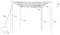
- FIG. 2is a perspective view of an exemplary embodiment of many energy collectors elevated above ground by a structure.
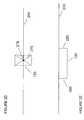
- FIG. 2Ais a side view of an energy collection fiber suspended from a support wire.
- FIG. 2Bis a side view of an exemplary embodiment of an energy collection fiber suspended from a support wire and with an additional support member.
- FIG. 2Cis a perspective view of a support structure for multiple energy collection fibers.
- FIG. 2Dis a side view of an exemplary embodiment of a support structure for multiple energy collection fibers.
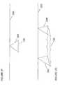
- FIG. 2Eis a side view of a support structure for an energy collection fiber.
- FIG. 2Fis a side view of an exemplary embodiment of a support structure for an energy collection fiber.
- FIG. 2Gis a side view of a support structure for multiple energy collection fibers.
- FIG. 3is a circuit diagram of an exemplary embodiment of a circuit for the collection of energy.
- FIG. 4is a circuit diagram of an exemplary embodiment of a circuit for the collection of energy.
- FIG. 5is a circuit diagram of an exemplary embodiment of an energy collection circuit for powering a generator and motor.
- FIG. 6is a circuit diagram of an exemplary embodiment of a circuit for collecting energy and using it for the production of hydrogen and oxygen.
- FIG. 7is a circuit diagram of an exemplary embodiment of a circuit for collecting energy, and using it for driving a fuel cell.
- FIG. 8is a circuit diagram of an exemplary embodiment of a circuit for collecting energy.
- FIG. 9is a flow diagram of an exemplary embodiment of collecting energy with a collection fiber.
- At least one collection device 130may be suspended from a support wire system 120 supported by poles 110 .
- Collection device 130may comprise a diode or a collection fiber individually, or the combination of a diode and a collection fiber.
- Support wire system 120may be electrically connected to load 150 by connecting wire 140 .
- Supporting wire system 120may be any shape or pattern.
- conducting wire 140may be one wire or multiple wires.
- the collection device 130 in the form of a fibermay comprise any conducting or non-conducting material, including carbon, graphite, Teflon, and metal.
- An exemplary embodimentutilizes carbon or graphite fibers for static electricity collection.
- Support wire system 120 and connecting wire 140can be made of any conducting material, including aluminum or steel, but most notably, copper. Teflon may be added to said conductor as well, such as non-limiting examples of a Teflon impregnated wire, a wire with a Teflon coating, or Teflon strips hanging from a wire.
- Conducting wire 120 , 140 , and 200may be bare wire, or coated with insulation as a non-limiting example. Wires 120 and 140 are a means of transporting the energy collected by collection device 130 .
- An exemplary embodiment of the collection fibers as collection device 130includes graphite or carbon fibers.
- Graphite and carbon fibersat a microscopic level, can have hundreds of thousands of points. Atmospheric electricity may be attracted to these points. If atmospheric electricity can follow two paths where one is a flat surface and the other is a pointy, conductive surface, the electrical charge will be attracted to the pointy, conductive surface. Generally, the more points that are present, the higher energy that can be gathered. Therefore, carbon, or graphite fibers are examples that demonstrate exemplary collection ability.
- the height of support wire 120may be an important factor. The higher that collection device 130 is from ground, the larger the voltage potential between collection device 130 and electrical ground. The electric field may be more than 100 volts per meter under some conditions. When support wire 120 is suspended in the air at a particular altitude, wire 120 will itself collect a very small charge from ambient voltage. When collection device 130 is connected to support wire 120 , collection device 130 becomes energized and transfers the energy to support wire 120 .
- a diodemay be connected in several positions in collection system 100 .
- a diodeis a component that restricts the direction of movement of charge carriers. It allows an electric current to flow in one direction, but essentially blocks it in the opposite direction.
- a diodecan be thought of as the electrical version of a check valve.
- the diodemay be used to prevent the collected energy from discharging into the atmosphere through the collection fiber embodiment of collection device 130 .
- An exemplary embodiment of the collection devicecomprises the diode with no collection fiber.
- a preferred embodimentincludes a diode at the connection point of a collection fiber to support system 120 such that the diode is elevated above ground. Multiple diodes may be used between collection device 130 and load 150 . Additionally, in an embodiment with multiple fibers, the diodes restricts energy that may be collected through one fiber from escaping through another fiber.
- Collection device 130may be connected and arranged in relation to support wire system 120 by many means. Some non-limiting examples are provided in FIGS. 2A-2G using a collection fiber embodiment.
- FIG. 2Apresents support wire 200 with connecting member 210 for collection device 130 .
- Connection member 210may be any conducting material allowing for the flow of electricity from connection device 130 to support wire 200 .
- the support wire 200 of support system 120may be electrically connected through conducting wire 140 to load 150 .
- a plurality of diodesmay be placed at any position on the support structure wire.
- a preferred embodimentplaces a diode at an elevated position at the connection point between a collection fiber embodiment of collection device 130 and connection member 210 .
- FIG. 2Bshows collection fiber 130 electrically connected to support wire 200 and also connected to support member 230 .
- Support member 230may be connected to collection fiber 130 on either side.
- Support member 230holds the fiber steady on both ends instead of letting it move freely.
- Support member 230may be conducting or non-conducting.
- a plurality of diodesmay be placed at any position on the support structure wire.
- a preferred embodimentplaces a diode at elevated position at the connection point between collection fiber 130 and support wire 200 or between fiber 130 , support member 230 , and support wire 200 .
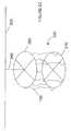
- FIG. 2Cpresents multiple collection fibers in a squirrel cage arrangement with top and bottom support members.
- Support structure 250may be connected to support structure wire 200 by support member 240 .
- Structure 250has a top 260 and a bottom 270 and each of the multiple collection fibers 130 are connected on one end to top 260 and on the other end to bottom 270 .
- a plurality of diodesmay be placed at any position on support structure 250 .
- a preferred embodimentplaces a diode at an elevated position at the connection point between collection fiber 130 and support structure wire 200 .
- FIG. 2Dpresents another exemplary embodiment of a support structure with support members 275 in an x-shape connected to support structure wire 200 at intersection 278 with collection fibers 130 connected between ends of support members 275 .
- a plurality of diodesmay be placed at any position on the support structure.
- a preferred embodimentplaces a diode at an elevated position at the connection point between collection fiber 130 and support wire 200 .
- FIG. 2Eprovides another exemplary embodiment for supporting collection fiber 130 .
- Collection fiber 130may be connected on one side to support member 285 , which may be connected to support structure wire 200 in a first location and on the other side to support member 280 , which may be connected to support structure wire 200 in a second location on support structure wire 200 .
- the first and second locationsmay be the same location, or they may be different locations, even on different support wires.
- a plurality of diodesmay be placed at any position on the support structure.
- a preferred embodimentplaces one or more diodes at elevated positions at the connection point(s) between collection fiber 130 and support wire 200 .
- FIG. 2Fpresents another exemplary embodiment of a support for a collection fiber.
- Two support members 290may support either side of a collection fiber and are connected to support wire 200 in a single point.
- a plurality of diodesmay be placed at any position on the support structure.
- a preferred embodimentplaces a diode at an elevated position at the connection point between collection fiber 130 and support wire 200 .
- FIG. 2Gprovides two supports as provided in FIG. 2F such that at least two support members 292 , 294 may be connected to support structure wire 200 in multiple locations and collection fibers 130 may be connected between each end of the support structures. Collection fibers 130 may be connected between each end of a single support structure and between multiple support structures. A plurality of diodes may be placed at any position on the support structure. A preferred embodiment places one or more diodes at elevated positions at the connection point(s) between collection fiber 130 and support structure wire 200 .
- FIG. 3provides a schematic diagram of storing circuit 300 for storing energy collected by one or more collection devices ( 130 from FIG. 2 ).
- Load 150induces current flow.
- Diode 310may be electrically connected in series between one or more collection devices ( 130 from FIG. 2 ) and load 150 .
- a plurality of diodesmay be placed at any position in the circuit.
- Switch 330may be electrically connected between load 150 and at least one collection device ( 130 from FIG. 2 ) to connect and disconnect the load.
- Capacitor 320may be connected in parallel to the switch 330 and load 150 to store energy when switch 330 is open for delivery to load 150 when switch 330 is closed.
- Rectifier 340may be electrically connected in parallel to load 150 , between the receiving end of switch 330 and ground.
- Rectifier 340may be a full-wave or a half-wave rectifier. Rectifier 340 may include a diode electrically connected in parallel to load 150 , between the receiving end of switch 330 and ground. The direction of the diode of rectifier 340 is optional.
- storage circuit 400stores energy from one or more collection devices ( 130 from FIG. 2 ) by charging capacitor 410 . If charging capacitor 410 is not used, then the connection to ground shown at capacitor 410 is eliminated.
- a plurality of diodesmay be placed at any position in the circuit. Diode 310 may be electrically connected in series between one or more collection devices ( 130 from FIG. 2 ) and load 150 . Diode 440 may be placed in series with load 150 .
- the voltage from capacitor 410can be used to charge spark gap 420 when it reaches sufficient voltage.
- Spark gap 420may comprise one or more spark gaps in parallel. Non-limiting examples of spark gap 420 include mercury-reed switches and mercury-wetted reed switches.
- spark gap 420When spark gap 420 arcs, energy will arc from one end of the spark gap 420 to the receiving end of the spark gap 420 .
- the output of spark gap 420may be electrically connected in series to rectifier 450 .
- Rectifier 450may be a full-wave or a half-wave rectifier.
- Rectifier 450may include a diode electrically connected in parallel to transformer 430 and load 150 , between the receiving end of spark gap 420 and ground. The direction of the diode of rectifier 450 is optional.
- the output of rectifier 450is connected to transformer 430 to drive load 150 .
- FIG. 5presents motor driver circuit 500 .
- One or more collection devices( 130 from FIG. 2 ) are electrically connected to static electricity motor 510 , which powers generator 520 to drive load 150 .
- a plurality of diodesmay be placed at any position in the circuit.
- Motor 510may also be directly connected to load 150 to drive it directly.
- FIG. 6demonstrates a circuit 600 for producing hydrogen.
- a plurality of diodesmay be placed at any position in the circuit.
- One or more collection devices( 130 from FIG. 2 ) are electrically connected to primary spark gap 610 , which may be connected to secondary spark gap 640 .
- Non-limiting examples of spark gaps 610 , 640include mercury-reed switches and mercury-wetted reed switches.
- Secondary spark gap 640may be immersed in water 630 within container 620 . When secondary spark gap 640 immersed in water 630 is energized, spark gap 640 may produce bubbles of hydrogen and oxygen, which may be collected to be used as fuel.
- FIG. 7presents circuit 700 for driving a fuel cell.
- a plurality of diodesmay be placed at any position in the circuit.
- Collection devices( 130 from FIG. 2 ) provide energy to fuel cell 720 which drives load 150 .
- Fuel cell 720may produce hydrogen and oxygen.
- FIG. 8presents exemplary circuit 800 for the collection of energy.
- Storage circuit 800stores energy from one or more collection devices ( 130 from FIG. 2 ) by charging capacitor 810 . If charging capacitor 810 is not used, then the connection to ground shown at capacitor 810 is eliminated. A plurality of diodes may be placed at any position in the circuit. The voltage from capacitor 810 can be used to charge spark gap 820 when it reaches sufficient voltage. Spark gap 820 may comprise one or more spark gaps in parallel or in series. Non-limiting examples of spark gap 820 include mercury-reed switches and mercury-wetted reed switches. When spark gap 820 arcs, energy will arc from one end of spark gap 820 to the receiving end of spark gap 820 .
- the output of spark gap 820may be electrically connected in series to rectifier 825 .
- Rectifier 825may be a full-wave or a half-wave rectifier.
- Rectifier 825may include a diode electrically connected in parallel to inductor 830 and load 150 , between the receiving end of spark gap 820 and ground. The direction of the diode of rectifier 825 is optional.
- the output of rectifier 825is connected to inductor 830 .
- Inductor 830may be a fixed value inductor or a variable inductor.
- Capacitor 870may be placed in parallel with load 150 .
- FIG. 9presents a flow diagram of a method for collecting energy.
- one or more collection devicesmay be suspended from a support structure wire.
- a loadmay be electrically connected to the support structure wire to draw current.
- a diodemay be electrically connected between the support structure wire and the electrical connection to the load.
- energy provided to the loadmay be stored or otherwise utilized.
Landscapes
- Chemical & Material Sciences (AREA)
- Chemical Kinetics & Catalysis (AREA)
- Charge And Discharge Circuits For Batteries Or The Like (AREA)
- Fuel Cell (AREA)
- Battery Electrode And Active Subsutance (AREA)
- Direct Current Feeding And Distribution (AREA)
- Carbon And Carbon Compounds (AREA)
- Cell Electrode Carriers And Collectors (AREA)
- Inert Electrodes (AREA)
- Current-Collector Devices For Electrically Propelled Vehicles (AREA)
- Wind Motors (AREA)
Abstract
Description
Claims (25)
Priority Applications (6)
| Application Number | Priority Date | Filing Date | Title |
|---|---|---|---|
| US12/255,130US8686575B2 (en) | 2006-02-21 | 2008-10-21 | Energy collection |
| US12/637,720US20100090562A1 (en) | 2006-02-21 | 2009-12-14 | Energy Collection |
| US12/637,724US20100090563A1 (en) | 2006-02-21 | 2009-12-14 | Energy Collection |
| US13/569,133US8810049B2 (en) | 2006-02-21 | 2012-08-07 | Energy collection |
| US14/242,464US9479086B2 (en) | 2006-02-21 | 2014-04-01 | Energy collection |
| US15/476,900US20180026553A1 (en) | 2008-10-21 | 2017-03-31 | Energy Collection |
Applications Claiming Priority (2)
| Application Number | Priority Date | Filing Date | Title |
|---|---|---|---|
| US11/358,264US7439712B2 (en) | 2006-02-21 | 2006-02-21 | Energy collection |
| US12/255,130US8686575B2 (en) | 2006-02-21 | 2008-10-21 | Energy collection |
Related Parent Applications (1)
| Application Number | Title | Priority Date | Filing Date |
|---|---|---|---|
| US11/358,264ContinuationUS7439712B2 (en) | 2006-02-21 | 2006-02-21 | Energy collection |
Related Child Applications (5)
| Application Number | Title | Priority Date | Filing Date |
|---|---|---|---|
| US12/637,720ContinuationUS20100090562A1 (en) | 2006-02-21 | 2009-12-14 | Energy Collection |
| US12/637,724ContinuationUS20100090563A1 (en) | 2006-02-21 | 2009-12-14 | Energy Collection |
| US13/569,133Continuation-In-PartUS8810049B2 (en) | 2006-02-21 | 2012-08-07 | Energy collection |
| US13/929,414ContinuationUS20150001966A1 (en) | 2008-10-21 | 2013-06-27 | Energy Collection |
| US14/242,464ContinuationUS9479086B2 (en) | 2006-02-21 | 2014-04-01 | Energy collection |
Publications (2)
| Publication Number | Publication Date |
|---|---|
| US20090040680A1 US20090040680A1 (en) | 2009-02-12 |
| US8686575B2true US8686575B2 (en) | 2014-04-01 |
Family
ID=38427952
Family Applications (8)
| Application Number | Title | Priority Date | Filing Date |
|---|---|---|---|
| US11/358,264Active - Reinstated2027-07-15US7439712B2 (en) | 2006-02-21 | 2006-02-21 | Energy collection |
| US11/839,112Expired - Fee RelatedUS7478712B2 (en) | 2006-02-21 | 2007-08-15 | Energy collection |
| US12/255,130Active - ReinstatedUS8686575B2 (en) | 2006-02-21 | 2008-10-21 | Energy collection |
| US12/350,387AbandonedUS20090114495A1 (en) | 2006-02-21 | 2009-01-08 | Energy Collection |
| US12/637,724AbandonedUS20100090563A1 (en) | 2006-02-21 | 2009-12-14 | Energy Collection |
| US12/637,720AbandonedUS20100090562A1 (en) | 2006-02-21 | 2009-12-14 | Energy Collection |
| US13/569,133Active - Reinstated2026-05-20US8810049B2 (en) | 2006-02-21 | 2012-08-07 | Energy collection |
| US14/242,464Expired - Fee RelatedUS9479086B2 (en) | 2006-02-21 | 2014-04-01 | Energy collection |
Family Applications Before (2)
| Application Number | Title | Priority Date | Filing Date |
|---|---|---|---|
| US11/358,264Active - Reinstated2027-07-15US7439712B2 (en) | 2006-02-21 | 2006-02-21 | Energy collection |
| US11/839,112Expired - Fee RelatedUS7478712B2 (en) | 2006-02-21 | 2007-08-15 | Energy collection |
Family Applications After (5)
| Application Number | Title | Priority Date | Filing Date |
|---|---|---|---|
| US12/350,387AbandonedUS20090114495A1 (en) | 2006-02-21 | 2009-01-08 | Energy Collection |
| US12/637,724AbandonedUS20100090563A1 (en) | 2006-02-21 | 2009-12-14 | Energy Collection |
| US12/637,720AbandonedUS20100090562A1 (en) | 2006-02-21 | 2009-12-14 | Energy Collection |
| US13/569,133Active - Reinstated2026-05-20US8810049B2 (en) | 2006-02-21 | 2012-08-07 | Energy collection |
| US14/242,464Expired - Fee RelatedUS9479086B2 (en) | 2006-02-21 | 2014-04-01 | Energy collection |
Country Status (16)
| Country | Link |
|---|---|
| US (8) | US7439712B2 (en) |
| EP (2) | EP1999767B8 (en) |
| JP (1) | JP5552236B2 (en) |
| CN (1) | CN101390177B (en) |
| CA (1) | CA2647385C (en) |
| CY (1) | CY1120609T1 (en) |
| DK (1) | DK1999767T3 (en) |
| ES (1) | ES2678408T3 (en) |
| HU (1) | HUE040308T2 (en) |
| LT (1) | LT1999767T (en) |
| PL (1) | PL1999767T3 (en) |
| PT (1) | PT1999767T (en) |
| RU (1) | RU2430455C2 (en) |
| SI (1) | SI1999767T1 (en) |
| TR (1) | TR201809560T4 (en) |
| WO (1) | WO2007098341A2 (en) |
Cited By (7)
| Publication number | Priority date | Publication date | Assignee | Title |
|---|---|---|---|---|
| US20120299559A1 (en)* | 2006-02-21 | 2012-11-29 | Mccowen Clint | Energy Collection |
| US20160043661A1 (en)* | 2014-08-07 | 2016-02-11 | Ion Power Group Llc | Energy Collection |
| US11588421B1 (en) | 2019-08-15 | 2023-02-21 | Robert M. Lyden | Receiver device of energy from the earth and its atmosphere |
| US20240021335A1 (en)* | 2022-07-13 | 2024-01-18 | Ion Power Group, Llc | Energy Collection With Radioactive Material |
| US12136824B2 (en) | 2019-08-15 | 2024-11-05 | Robert M. Lyden | Device for receiving and harvesting energy from the earth and its atmosphere |
| US12237690B2 (en) | 2017-05-23 | 2025-02-25 | Atlas Power Technologies Inc. | System and method of collecting energy utilizing a management system for an energy collection device, for collecting, managing, and discharging energy |
| US20250126696A1 (en)* | 2023-10-13 | 2025-04-17 | Ion Power Group Llc | Frayed Energy Collectors |
Families Citing this family (27)
| Publication number | Priority date | Publication date | Assignee | Title |
|---|---|---|---|---|
| US6682174B2 (en)* | 1998-03-25 | 2004-01-27 | Silverbrook Research Pty Ltd | Ink jet nozzle arrangement configuration |
| US20100207399A1 (en)* | 2006-07-03 | 2010-08-19 | Peter Grandics | Pyramid electric generator |
| CN102007680B (en) | 2008-01-22 | 2014-01-08 | 阿齐欧能源公司 | Electro-hydrodynamic wind energy system |
| US8878150B2 (en) | 2008-01-22 | 2014-11-04 | Accio Energy, Inc. | Electro-hydrodynamic wind energy system |
| US8502507B1 (en)* | 2012-03-29 | 2013-08-06 | Accio Energy, Inc. | Electro-hydrodynamic system |
| US20150001966A1 (en)* | 2013-06-27 | 2015-01-01 | Ion Power Group Llc | Energy Collection |
| US9179531B2 (en)* | 2010-05-02 | 2015-11-03 | Melito Inc | Super conducting super capacitor |
| EP2630724A4 (en) | 2010-10-18 | 2018-01-03 | Accio Energy, Inc. | System and method for controlling electric fields in electro-hydrodynamic applications |
| WO2013145002A1 (en)* | 2012-03-28 | 2013-10-03 | 株式会社 日立製作所 | Power storage system and power storage method |
| US20150102676A1 (en)* | 2013-10-11 | 2015-04-16 | Earth Energies, Inc. | Method and Apparatus for Extracting and Conveying Electrical Energy From the Earth's Ionosphere Cavity |
| US10389138B2 (en) | 2013-10-11 | 2019-08-20 | Earth Energies, Inc. | Power receiver for extracting power from electric field energy in the earth |
| CN103915768A (en)* | 2014-04-03 | 2014-07-09 | 余姚市电力设备修造厂 | Intelligent electricity-saving dehumidifying switch cabinet |
| EA028417B1 (en)* | 2015-06-18 | 2017-11-30 | Борис Иванович Блескин | Marine device for usage of atmospheric electricity "ruselectro 3" |
| PT3430697T (en)* | 2016-03-14 | 2020-11-25 | Univ Do Porto | Triboelectric turbine for generating electricity from the motion of fluids |
| KR20180059086A (en) | 2016-11-25 | 2018-06-04 | 경희대학교 산학협력단 | Generator and mobile device having the same |
| GB2560363B (en)* | 2017-03-09 | 2019-09-11 | Ionech Ltd | Energy storage and conversion |
| EA034109B1 (en)* | 2018-01-11 | 2019-12-27 | Борис Иванович Блескин | Electric motor using atmospheric electricity |
| CN108198689A (en)* | 2018-01-19 | 2018-06-22 | 邱柏康 | Condenser type pressure regulation current divider and charge obtain equipment |
| CN108260268B (en)* | 2018-01-19 | 2021-07-09 | 邱柏康 | Charge acquisition device and method |
| EA037097B1 (en)* | 2018-01-31 | 2021-02-05 | Борис Иванович Блескин | Electric power plant using atmospheric electricity |
| GB201814767D0 (en) | 2018-09-11 | 2018-10-24 | Ionech Ltd | Energy storage and conversion |
| JP7221402B2 (en)* | 2018-10-04 | 2023-02-13 | イオン-エネルギー ビー.ブイ. | Device for converting atmospheric energy and method for manufacturing same |
| US20200245440A1 (en)* | 2019-01-28 | 2020-07-30 | Maxwell Loughan | Methods and devices for harvesting ionic energy to produce electricity |
| CN110286293B (en)* | 2019-07-25 | 2021-04-20 | 云南电网有限责任公司电力科学研究院 | Self-energy-taking leakage monitoring method and system based on leakage current |
| CN110286294B (en)* | 2019-07-25 | 2021-04-20 | 云南电网有限责任公司电力科学研究院 | A self-energy harvesting device and method for leakage monitoring |
| KR102720569B1 (en)* | 2022-05-17 | 2024-10-24 | 중앙대학교 산학협력단 | Triboelectric nanogenerator using film capacitor and operating method thereof |
| WO2024130362A1 (en)* | 2022-12-19 | 2024-06-27 | Evoluções Cientificas E Tecnologicas Ltda | Resonant systems for capturing electric charges from the earth and use of a method for transferring electric charges from the earth through electric power circuits |
Citations (70)
| Publication number | Priority date | Publication date | Assignee | Title |
|---|---|---|---|---|
| US674427A (en) | 1900-07-10 | 1901-05-21 | Andor Palencsar | Apparatus for collecting atmospheric electricity. |
| US911260A (en) | 1907-06-26 | 1909-02-02 | Walter I Pennock | Apparatus for collecting atmospheric electricity. |
| US1014719A (en) | 1911-01-04 | 1912-01-16 | Walter I Pennock | Apparatus for collecting electrical energy. |
| US2473819A (en)* | 1946-07-12 | 1949-06-21 | Ralph R Pittman | Multiple gap arc interrupter |
| US3532959A (en)* | 1968-08-19 | 1970-10-06 | Us Navy | Voltage reversal concellation on series connected capacitors |
| US3780722A (en)* | 1972-04-26 | 1973-12-25 | Us Navy | Fiber optical solar collector |
| US3946227A (en) | 1973-04-12 | 1976-03-23 | Associated Electrical Industires Limited | Mass spectrographs and ion collector systems therefor |
| US4079225A (en)* | 1976-08-04 | 1978-03-14 | Warner Allan S | Fiber optic/photon detector for brazing machine |
| US4092250A (en) | 1975-08-12 | 1978-05-30 | Sumitomo Chemical Company, Limited | Filters for the selective collection of metallic ions |
| US4104696A (en) | 1977-05-27 | 1978-08-01 | Frontier Electronics, Inc. | Grid wire support |
| US4146800A (en)* | 1975-10-08 | 1979-03-27 | Gregory Stephen E | Apparatus and method of generating electricity from wind energy |
| US4180056A (en)* | 1976-01-30 | 1979-12-25 | Jenaer Glaswerk Schott & Gen. | Laminar solar energy collecting unit having absorber plates consisting of hollow fibers |
| US4201197A (en)* | 1978-03-20 | 1980-05-06 | Dismer Raymond H | Solar energy collector having a fiber-optic cable |
| US4206396A (en)* | 1977-08-29 | 1980-06-03 | Marks Alvin M | Charged aerosol generator with uni-electrode source |
| US4224496A (en)* | 1978-10-12 | 1980-09-23 | Joyal Products, Inc. | Method and apparatus for controlling a brazing machine |
| US4307936A (en)* | 1979-09-17 | 1981-12-29 | Tsurunosuke Ochiai | System for collecting solar energy |
| US4314192A (en)* | 1979-11-01 | 1982-02-02 | Cwm Corporation | Electrical power generation apparatus and method utilizing electron beam discharge |
| US4346478A (en)* | 1980-12-01 | 1982-08-24 | Siemens Corporation | Fiber optical sensor system, preferably for measuring physical parameters |
| US4425905A (en)* | 1981-07-18 | 1984-01-17 | Kei Mori | Sunlight collecting and concentrating apparatus |
| US4433248A (en)* | 1982-04-07 | 1984-02-21 | Marks Alvin M | Charged aerosol wind/electric power generator with solar and/or gravitational regeneration |
| USRE31678E (en)* | 1979-09-17 | 1984-09-18 | System for collecting solar energy | |
| US4483311A (en)* | 1981-09-21 | 1984-11-20 | Whitaker Ranald O | Solar power system utilizing optical fibers, each fiber fed by a respective lens |
| US4489269A (en)* | 1982-12-01 | 1984-12-18 | Edling Ellsworth A | Atomic battery with beam switching |
| US4512335A (en)* | 1982-04-03 | 1985-04-23 | Kei Mori | Solar energy collecting apparatus |
| US4653472A (en)* | 1984-08-31 | 1987-03-31 | Kei Mori | Solar ray energy collecting device |
| US4653223A (en)* | 1983-07-01 | 1987-03-31 | Kei Mori | Apparatus for plant culture |
| US4676226A (en)* | 1985-07-09 | 1987-06-30 | Kei Mori | Light rays bathtub |
| US4809675A (en)* | 1986-09-18 | 1989-03-07 | Kei Mori | Solar ray collecting device |
| US4852454A (en)* | 1987-11-10 | 1989-08-01 | Batchelder J Samuel | Method and apparatus for delivering electric currents to remote targets |
| US4943125A (en)* | 1989-01-26 | 1990-07-24 | Laundre John W | Solar collector |
| US4988159A (en)* | 1987-08-19 | 1991-01-29 | Stc Plc | Fiber tailed optoelectronic transducer |
| US5047892A (en) | 1989-03-07 | 1991-09-10 | Takasago Thermal Engineering Co., Ltd. | Apparatus for removing static electricity from charged articles existing in clean space |
| US5114101A (en)* | 1989-09-28 | 1992-05-19 | General Dynamics Corporation/Space Systems Division | Modular distributed concentrating collector using power bus to route power to centralized converter |
| US5145257A (en)* | 1990-03-29 | 1992-09-08 | The United States Of America As Represented By The Secretary Of The Navy | Infrared fiber-optical temperature sensor |
| US5379103A (en)* | 1993-05-06 | 1995-01-03 | Apti, Inc. | Method and apparatus for in situ detection of minute amounts of trace elements |
| US5851309A (en)* | 1996-04-26 | 1998-12-22 | Kousa; Paavo | Directing and concentrating solar energy collectors |
| US5942806A (en)* | 1996-08-08 | 1999-08-24 | Veliadis; Konstantinos D. | Method and device for generating electricity |
| US6025591A (en) | 1995-04-04 | 2000-02-15 | University Of Liverpool | Quadrupole mass spectrometers |
| US6038363A (en)* | 1996-08-30 | 2000-03-14 | Kaiser Optical Systems | Fiber-optic spectroscopic probe with reduced background luminescence |
| US6116544A (en)* | 1997-09-12 | 2000-09-12 | Tethers Unlimited, Inc. | Electrodynamic tether and method of use |
| US6173922B1 (en)* | 1997-04-22 | 2001-01-16 | Robert P. Hoyt | Failure resistant multiline tether |
| US6226440B1 (en)* | 1996-09-16 | 2001-05-01 | Whelen Engineering Company, Inc. | Optical coupler and illumination system employing the same |
| US20020026933A1 (en)* | 2000-09-07 | 2002-03-07 | Gottlieb Martha M. | Carbon/carbon heat collection storage and dissipation system |
| US6419191B1 (en)* | 1997-09-12 | 2002-07-16 | Robert P. Hoyt | Electrodynamic tether control |
| US6425391B1 (en)* | 2001-05-23 | 2002-07-30 | Jeffrey A. Davoren | Electromagnetic radiation collector system |
| US20020108892A1 (en)* | 2001-02-12 | 2002-08-15 | Alexander Goetz | System and method for grouping refelectance data |
| US20020109835A1 (en)* | 2001-02-12 | 2002-08-15 | Alexander Goetz | System and method for the collection of spectral image data |
| US20020109094A1 (en)* | 2001-02-12 | 2002-08-15 | Alexander Goetz | System and method for combining reflectance data |
| US20030107869A1 (en) | 2001-12-07 | 2003-06-12 | Avaya Technology Corporation | Capacitor employing both fringe and plate capacitance and method of manufacture thereof |
| US20030125630A1 (en)* | 2001-12-31 | 2003-07-03 | Furnish Simon M. | Catheter probe arrangement for tissue analysis by radiant energy delivery and radiant energy collection |
| US20030193319A1 (en)* | 2002-04-12 | 2003-10-16 | Wood James Rick | Ion powered platform |
| US20040011925A1 (en)* | 1999-12-07 | 2004-01-22 | Peter Grandics | Method and apparatus for converting electrostatic potential energy |
| US20040083793A1 (en)* | 2002-11-05 | 2004-05-06 | Kenneth Susko | Oxygen monitoring device |
| US6735830B1 (en) | 1999-05-31 | 2004-05-18 | Genie Et Environnement | Ion generating device |
| US20040094853A1 (en)* | 2002-11-14 | 2004-05-20 | Mbachu Reginald A. | Methods for monitoring resin-loading of wood materials and engineered wood products |
| US20040160711A1 (en) | 2002-03-11 | 2004-08-19 | Stumberger Walter William | Methods for delivering continuous electrical power offering physical and dielecrtic isolation |
| US20050136311A1 (en)* | 2000-10-03 | 2005-06-23 | Tetsuya Ueda | Power generation control system, power generation control method, program, and medium |
| US7109597B1 (en)* | 2002-11-12 | 2006-09-19 | Bose Phillip R | Electrical energy generating system |
| US20070107765A1 (en)* | 2005-11-14 | 2007-05-17 | Schutten Michael J | Optically powered drive circuit and method for controlling a semiconductor switch |
| US7259475B2 (en)* | 2003-07-03 | 2007-08-21 | Eppscore Co., Ltd. | Uninterruptible power supply for the backup of AC-power supply |
| US20070195481A1 (en)* | 2006-02-21 | 2007-08-23 | Mccowen Clint | Energy collection |
| US20070218323A1 (en)* | 2004-09-06 | 2007-09-20 | Sony Corporation | Methods of Operating Fuel Cell Power Generators, and Fuel Cell Power Generators |
| US20070223171A1 (en) | 2003-12-30 | 2007-09-27 | Lafon Guy | Protector Device with Improved Capacity to Break Follow Current |
| US20070297892A1 (en)* | 2004-01-16 | 2007-12-27 | Casper Kildegaard | Monitoring the Operation of a Wind Energy Plant |
| US20080145714A1 (en)* | 2004-02-13 | 2008-06-19 | Nissan Motor Co., Ltd. | Fuel Cell System and Related Method |
| US20090107842A1 (en) | 2007-10-24 | 2009-04-30 | Samsung Electronics Co., Ltd. | Method for manufacturing polyimide-based carbon nanofiber electrode and/or carbon nanotube composite electrode and CDI apparatus using the electrode |
| US7532819B1 (en)* | 2003-02-12 | 2009-05-12 | Lockheed Martin Corporation | Refractive multi-beam laser communications terminal |
| US20090216292A1 (en)* | 2008-02-25 | 2009-08-27 | Benjamin David Pless | Devices, methods, and systems for harvesting energy in the body |
| US20120164555A1 (en)* | 2009-09-24 | 2012-06-28 | Kabushiki Kaisha Toshiba | Collector member, power generator, and method of manufacturing collector member for power generator |
| US20130276776A1 (en)* | 2012-04-24 | 2013-10-24 | Rodomach Speciaalmachines B.V. | Method for producing an absorber for a solar collector, and a solar collector |
Family Cites Families (40)
| Publication number | Priority date | Publication date | Assignee | Title |
|---|---|---|---|---|
| US3663360A (en)* | 1970-08-13 | 1972-05-16 | Atomic Energy Commission | Conversion of high temperature plasma energy into electrical energy |
| US3668065A (en)* | 1970-09-15 | 1972-06-06 | Atomic Energy Commission | Apparatus for the conversion of high temperature plasma energy into electrical energy |
| DE2536773C3 (en)* | 1975-08-19 | 1978-11-30 | Troponwerke Gmbh & Co Kg, 5000 Koeln | Thermographic plate for measuring temperature distributions |
| US5862035A (en)* | 1994-10-07 | 1999-01-19 | Maxwell Energy Products, Inc. | Multi-electrode double layer capacitor having single electrolyte seal and aluminum-impregnated carbon cloth electrodes |
| JP3386323B2 (en)* | 1996-11-13 | 2003-03-17 | 慎二 千葉 | Generator |
| JPH10257711A (en)* | 1997-03-07 | 1998-09-25 | Toshihiko Yamashita | Power generating method and apparatus |
| JP3444769B2 (en)* | 1997-11-25 | 2003-09-08 | 東洋アルミニウム株式会社 | Aluminum foil for current collector and manufacturing method thereof, current collector, secondary battery and electric double layer capacitor |
| JP3084521B2 (en)* | 1998-02-05 | 2000-09-04 | セイコーインスツルメンツ株式会社 | Electronic equipment with generator |
| DK173460B2 (en)* | 1998-09-09 | 2004-08-30 | Lm Glasfiber As | Windmill wing with lightning conductor |
| CN1161166C (en)* | 2000-03-14 | 2004-08-11 | A·C·奥伯 | Personal Body Grounding System |
| US6936994B1 (en)* | 2002-09-03 | 2005-08-30 | Gideon Gimlan | Electrostatic energy generators and uses of same |
| JP2004229481A (en)* | 2003-01-20 | 2004-08-12 | Koken Kk | Power generating method by wave motion |
| US6920031B2 (en)* | 2003-04-24 | 2005-07-19 | Velcon Filters, Inc. | Static charge neutralizer |
| US20060051207A1 (en)* | 2004-09-03 | 2006-03-09 | Becerra Steven R | Light emitting diode array mounted within windmill wing tip |
| ES2255454B1 (en)* | 2004-12-15 | 2007-07-01 | Gamesa Eolica, S.A. | PARARRAYOS SYSTEM FOR AEROGENERATOR SHOVEL. |
| US7303373B2 (en)* | 2005-10-31 | 2007-12-04 | General Electric Company | Wind turbine systems, monitoring systems and processes for monitoring stress in a wind turbine blade |
| JP3118465U (en)* | 2005-11-10 | 2006-01-26 | 株式会社中電工 | Portable independent solar power generation system |
| US7517198B2 (en)* | 2006-03-20 | 2009-04-14 | Modular Wind Energy, Inc. | Lightweight composite truss wind turbine blade |
| US7637462B2 (en)* | 2006-04-28 | 2009-12-29 | Anadish Kumar Pal | Surface flow diverting and static charging ducted pores on wing or blade tip to reduce wake and BVI noise |
| JP2008160053A (en)* | 2006-11-27 | 2008-07-10 | Denso Corp | Electric current collector, electrode and electric charge storing device |
| US8937399B2 (en)* | 2007-12-10 | 2015-01-20 | V Squared Wind, Inc. | Efficient systems and methods for construction and operation of mobile wind power platforms |
| GB2463117A (en) | 2008-09-08 | 2010-03-10 | Landa Lab Ltd | Generating electricity from the thermal motion of gas molecules |
| US8629570B1 (en)* | 2009-04-08 | 2014-01-14 | Kamen George Kamenov | Wind turbine blades with reinforcing, supporting and stabilizing components and enlarged swept area |
| WO2010118517A1 (en)* | 2009-04-13 | 2010-10-21 | 1066626 Ontario Ltd. | Wind turbine blade and method of constructing same |
| US8342805B2 (en)* | 2009-06-25 | 2013-01-01 | General Electric Company | Transversal conduction lightning protection system |
| US8550786B2 (en)* | 2009-12-11 | 2013-10-08 | Peter Janiuk | Vertical axis wind turbine with self-starting capabilities |
| US8115333B2 (en)* | 2010-06-23 | 2012-02-14 | Harris Corporation | Wind turbine providing reduced radio frequency interaction and related methods |
| US8309418B2 (en) | 2010-08-23 | 2012-11-13 | International Business Machines Corporation | Field effect transistor device with shaped conduction channel |
| ES2396839B1 (en)* | 2010-11-30 | 2014-01-02 | Gamesa Innovation & Technology, S.L. | PARARRAYOS SYSTEM FOR AEROGENERATOR SHOVEL WITH CARBON FIBER LAMINATES. |
| US9139279B2 (en)* | 2011-03-15 | 2015-09-22 | Stratospheric Airships, Llc | Systems and methods for long endurance airship operations |
| US8864063B2 (en)* | 2011-06-13 | 2014-10-21 | Stratospheric Airships, Llc | Tethered airships |
| FI20115536A7 (en)* | 2011-05-31 | 2013-03-25 | Wicetec Oy | Wind turbine blade and related method of manufacture |
| US9835141B2 (en)* | 2011-07-28 | 2017-12-05 | Vestas Wind Systems A/S | Wind turbine blade and a lightning measurement system therein |
| US9327839B2 (en)* | 2011-08-05 | 2016-05-03 | General Atomics | Method and apparatus for inhibiting formation of and/or removing ice from aircraft components |
| US9178446B2 (en) | 2011-08-30 | 2015-11-03 | Georgia Tech Research Corporation | Triboelectric generator |
| DK2597305T3 (en)* | 2011-11-24 | 2016-06-20 | Nordex Energy Gmbh | Wind turbine rotor blade with a heating means and method for producing the same |
| US8269401B1 (en) | 2011-11-28 | 2012-09-18 | K-Technology, Inc. | Graphene power-mill system |
| EP2602455B1 (en)* | 2011-12-07 | 2015-02-11 | Nordex Energy GmbH | Wind energy assembly rotor blade with an electrical heating element |
| US9595894B2 (en)* | 2012-09-21 | 2017-03-14 | Georgia Tech Research Corporation | Triboelectric nanogenerator for powering portable electronics |
| US8519596B1 (en)* | 2013-01-23 | 2013-08-27 | K-Technology Usa, Inc. | Graphene triboelectric charging device and a method of generating electricity by the same |
- 2006
- 2006-02-21USUS11/358,264patent/US7439712B2/enactiveActive - Reinstated
- 2007
- 2007-02-14HUHUE07756971Apatent/HUE040308T2/enunknown
- 2007-02-14CACA2647385Apatent/CA2647385C/ennot_activeExpired - Fee Related
- 2007-02-14WOPCT/US2007/062114patent/WO2007098341A2/enactiveApplication Filing
- 2007-02-14SISI200732041Tpatent/SI1999767T1/enunknown
- 2007-02-14EPEP07756971.3Apatent/EP1999767B8/enactiveActive
- 2007-02-14EPEP08172262Apatent/EP2043411A2/ennot_activeWithdrawn
- 2007-02-14PLPL07756971Tpatent/PL1999767T3/enunknown
- 2007-02-14TRTR2018/09560Tpatent/TR201809560T4/enunknown
- 2007-02-14LTLTEP07756971.3Tpatent/LT1999767T/enunknown
- 2007-02-14ESES07756971.3Tpatent/ES2678408T3/enactiveActive
- 2007-02-14DKDK07756971.3Tpatent/DK1999767T3/enactive
- 2007-02-14JPJP2008556498Apatent/JP5552236B2/enactiveActive
- 2007-02-14CNCN2007800062097Apatent/CN101390177B/enactiveActive
- 2007-02-14PTPT77569713Tpatent/PT1999767T/enunknown
- 2007-02-14RURU2008137622/07Apatent/RU2430455C2/ennot_activeIP Right Cessation
- 2007-08-15USUS11/839,112patent/US7478712B2/ennot_activeExpired - Fee Related
- 2008
- 2008-10-21USUS12/255,130patent/US8686575B2/enactiveActive - Reinstated
- 2009
- 2009-01-08USUS12/350,387patent/US20090114495A1/ennot_activeAbandoned
- 2009-12-14USUS12/637,724patent/US20100090563A1/ennot_activeAbandoned
- 2009-12-14USUS12/637,720patent/US20100090562A1/ennot_activeAbandoned
- 2012
- 2012-08-07USUS13/569,133patent/US8810049B2/enactiveActive - Reinstated
- 2014
- 2014-04-01USUS14/242,464patent/US9479086B2/ennot_activeExpired - Fee Related
- 2018
- 2018-07-04CYCY181100704Tpatent/CY1120609T1/enunknown
Patent Citations (89)
| Publication number | Priority date | Publication date | Assignee | Title |
|---|---|---|---|---|
| US674427A (en) | 1900-07-10 | 1901-05-21 | Andor Palencsar | Apparatus for collecting atmospheric electricity. |
| US911260A (en) | 1907-06-26 | 1909-02-02 | Walter I Pennock | Apparatus for collecting atmospheric electricity. |
| US1014719A (en) | 1911-01-04 | 1912-01-16 | Walter I Pennock | Apparatus for collecting electrical energy. |
| US2473819A (en)* | 1946-07-12 | 1949-06-21 | Ralph R Pittman | Multiple gap arc interrupter |
| US3532959A (en)* | 1968-08-19 | 1970-10-06 | Us Navy | Voltage reversal concellation on series connected capacitors |
| US3780722A (en)* | 1972-04-26 | 1973-12-25 | Us Navy | Fiber optical solar collector |
| US3946227A (en) | 1973-04-12 | 1976-03-23 | Associated Electrical Industires Limited | Mass spectrographs and ion collector systems therefor |
| US4092250A (en) | 1975-08-12 | 1978-05-30 | Sumitomo Chemical Company, Limited | Filters for the selective collection of metallic ions |
| US4146800A (en)* | 1975-10-08 | 1979-03-27 | Gregory Stephen E | Apparatus and method of generating electricity from wind energy |
| US4180056A (en)* | 1976-01-30 | 1979-12-25 | Jenaer Glaswerk Schott & Gen. | Laminar solar energy collecting unit having absorber plates consisting of hollow fibers |
| US4079225A (en)* | 1976-08-04 | 1978-03-14 | Warner Allan S | Fiber optic/photon detector for brazing machine |
| US4104696A (en) | 1977-05-27 | 1978-08-01 | Frontier Electronics, Inc. | Grid wire support |
| US4206396A (en)* | 1977-08-29 | 1980-06-03 | Marks Alvin M | Charged aerosol generator with uni-electrode source |
| US4201197A (en)* | 1978-03-20 | 1980-05-06 | Dismer Raymond H | Solar energy collector having a fiber-optic cable |
| US4224496A (en)* | 1978-10-12 | 1980-09-23 | Joyal Products, Inc. | Method and apparatus for controlling a brazing machine |
| US4307936A (en)* | 1979-09-17 | 1981-12-29 | Tsurunosuke Ochiai | System for collecting solar energy |
| USRE31678E (en)* | 1979-09-17 | 1984-09-18 | System for collecting solar energy | |
| US4314192A (en)* | 1979-11-01 | 1982-02-02 | Cwm Corporation | Electrical power generation apparatus and method utilizing electron beam discharge |
| US4346478A (en)* | 1980-12-01 | 1982-08-24 | Siemens Corporation | Fiber optical sensor system, preferably for measuring physical parameters |
| US4425905A (en)* | 1981-07-18 | 1984-01-17 | Kei Mori | Sunlight collecting and concentrating apparatus |
| US4483311A (en)* | 1981-09-21 | 1984-11-20 | Whitaker Ranald O | Solar power system utilizing optical fibers, each fiber fed by a respective lens |
| US4512335A (en)* | 1982-04-03 | 1985-04-23 | Kei Mori | Solar energy collecting apparatus |
| US4433248A (en)* | 1982-04-07 | 1984-02-21 | Marks Alvin M | Charged aerosol wind/electric power generator with solar and/or gravitational regeneration |
| US4489269A (en)* | 1982-12-01 | 1984-12-18 | Edling Ellsworth A | Atomic battery with beam switching |
| US4653223A (en)* | 1983-07-01 | 1987-03-31 | Kei Mori | Apparatus for plant culture |
| US4653472A (en)* | 1984-08-31 | 1987-03-31 | Kei Mori | Solar ray energy collecting device |
| US4676226A (en)* | 1985-07-09 | 1987-06-30 | Kei Mori | Light rays bathtub |
| US4809675A (en)* | 1986-09-18 | 1989-03-07 | Kei Mori | Solar ray collecting device |
| US4988159A (en)* | 1987-08-19 | 1991-01-29 | Stc Plc | Fiber tailed optoelectronic transducer |
| US4852454A (en)* | 1987-11-10 | 1989-08-01 | Batchelder J Samuel | Method and apparatus for delivering electric currents to remote targets |
| US4943125A (en)* | 1989-01-26 | 1990-07-24 | Laundre John W | Solar collector |
| US5047892A (en) | 1989-03-07 | 1991-09-10 | Takasago Thermal Engineering Co., Ltd. | Apparatus for removing static electricity from charged articles existing in clean space |
| US5114101A (en)* | 1989-09-28 | 1992-05-19 | General Dynamics Corporation/Space Systems Division | Modular distributed concentrating collector using power bus to route power to centralized converter |
| US5145257A (en)* | 1990-03-29 | 1992-09-08 | The United States Of America As Represented By The Secretary Of The Navy | Infrared fiber-optical temperature sensor |
| US5379103A (en)* | 1993-05-06 | 1995-01-03 | Apti, Inc. | Method and apparatus for in situ detection of minute amounts of trace elements |
| US6025591A (en) | 1995-04-04 | 2000-02-15 | University Of Liverpool | Quadrupole mass spectrometers |
| US5851309A (en)* | 1996-04-26 | 1998-12-22 | Kousa; Paavo | Directing and concentrating solar energy collectors |
| US5942806A (en)* | 1996-08-08 | 1999-08-24 | Veliadis; Konstantinos D. | Method and device for generating electricity |
| US6038363A (en)* | 1996-08-30 | 2000-03-14 | Kaiser Optical Systems | Fiber-optic spectroscopic probe with reduced background luminescence |
| US6226440B1 (en)* | 1996-09-16 | 2001-05-01 | Whelen Engineering Company, Inc. | Optical coupler and illumination system employing the same |
| US6173922B1 (en)* | 1997-04-22 | 2001-01-16 | Robert P. Hoyt | Failure resistant multiline tether |
| US6116544A (en)* | 1997-09-12 | 2000-09-12 | Tethers Unlimited, Inc. | Electrodynamic tether and method of use |
| US6419191B1 (en)* | 1997-09-12 | 2002-07-16 | Robert P. Hoyt | Electrodynamic tether control |
| US6735830B1 (en) | 1999-05-31 | 2004-05-18 | Genie Et Environnement | Ion generating device |
| US6974110B2 (en) | 1999-12-07 | 2005-12-13 | Peter Grandics | Method and apparatus for converting electrostatic potential energy |
| US20040011925A1 (en)* | 1999-12-07 | 2004-01-22 | Peter Grandics | Method and apparatus for converting electrostatic potential energy |
| US20020026933A1 (en)* | 2000-09-07 | 2002-03-07 | Gottlieb Martha M. | Carbon/carbon heat collection storage and dissipation system |
| US20050136311A1 (en)* | 2000-10-03 | 2005-06-23 | Tetsuya Ueda | Power generation control system, power generation control method, program, and medium |
| US20020108892A1 (en)* | 2001-02-12 | 2002-08-15 | Alexander Goetz | System and method for grouping refelectance data |
| US6853447B2 (en)* | 2001-02-12 | 2005-02-08 | Analytical Spectral Devices, Inc. | System and method for the collection of spectral image data |
| US20020109835A1 (en)* | 2001-02-12 | 2002-08-15 | Alexander Goetz | System and method for the collection of spectral image data |
| US6894772B2 (en)* | 2001-02-12 | 2005-05-17 | Analytical Spectral Devices | System and method for grouping reflectance data |
| US6765212B2 (en)* | 2001-02-12 | 2004-07-20 | Analytical Spectral Devices, Inc. | System and method for combining reflectance data |
| US20020109094A1 (en)* | 2001-02-12 | 2002-08-15 | Alexander Goetz | System and method for combining reflectance data |
| US6425391B1 (en)* | 2001-05-23 | 2002-07-30 | Jeffrey A. Davoren | Electromagnetic radiation collector system |
| US20030107869A1 (en) | 2001-12-07 | 2003-06-12 | Avaya Technology Corporation | Capacitor employing both fringe and plate capacitance and method of manufacture thereof |
| US20030125630A1 (en)* | 2001-12-31 | 2003-07-03 | Furnish Simon M. | Catheter probe arrangement for tissue analysis by radiant energy delivery and radiant energy collection |
| US20040160711A1 (en) | 2002-03-11 | 2004-08-19 | Stumberger Walter William | Methods for delivering continuous electrical power offering physical and dielecrtic isolation |
| US20030193319A1 (en)* | 2002-04-12 | 2003-10-16 | Wood James Rick | Ion powered platform |
| US20040083793A1 (en)* | 2002-11-05 | 2004-05-06 | Kenneth Susko | Oxygen monitoring device |
| US7231809B2 (en)* | 2002-11-05 | 2007-06-19 | Kenneth Susko | Oxygen monitoring device |
| US6925852B2 (en)* | 2002-11-05 | 2005-08-09 | Kenneth Susko | Oxygen monitoring device |
| US20050270525A1 (en)* | 2002-11-05 | 2005-12-08 | Kenneth Susko | Oxygen monitoring device |
| US7109597B1 (en)* | 2002-11-12 | 2006-09-19 | Bose Phillip R | Electrical energy generating system |
| US20040094853A1 (en)* | 2002-11-14 | 2004-05-20 | Mbachu Reginald A. | Methods for monitoring resin-loading of wood materials and engineered wood products |
| US20050101024A1 (en)* | 2002-11-14 | 2005-05-12 | Dynea Chemicals Oy | Methods for monitoring resin-loading of wood materials and engineered wood products |
| US7128867B2 (en)* | 2002-11-14 | 2006-10-31 | Dynea Chemicals Oy | Methods for monitoring resin-loading of wood materials and engineered wood products |
| US6846447B2 (en)* | 2002-11-14 | 2005-01-25 | Dynea Chemicals Oy | Methods for monitoring resin-loading of wood materials and engineered wood products |
| US7532819B1 (en)* | 2003-02-12 | 2009-05-12 | Lockheed Martin Corporation | Refractive multi-beam laser communications terminal |
| US7259475B2 (en)* | 2003-07-03 | 2007-08-21 | Eppscore Co., Ltd. | Uninterruptible power supply for the backup of AC-power supply |
| US20070223171A1 (en) | 2003-12-30 | 2007-09-27 | Lafon Guy | Protector Device with Improved Capacity to Break Follow Current |
| US20070297892A1 (en)* | 2004-01-16 | 2007-12-27 | Casper Kildegaard | Monitoring the Operation of a Wind Energy Plant |
| US20080145714A1 (en)* | 2004-02-13 | 2008-06-19 | Nissan Motor Co., Ltd. | Fuel Cell System and Related Method |
| US20070218323A1 (en)* | 2004-09-06 | 2007-09-20 | Sony Corporation | Methods of Operating Fuel Cell Power Generators, and Fuel Cell Power Generators |
| US20070107765A1 (en)* | 2005-11-14 | 2007-05-17 | Schutten Michael J | Optically powered drive circuit and method for controlling a semiconductor switch |
| US7449668B2 (en)* | 2005-11-14 | 2008-11-11 | General Electric Company | Optically powered drive circuit and method for controlling a semiconductor switch |
| US20090114495A1 (en)* | 2006-02-21 | 2009-05-07 | Mccowen Clint | Energy Collection |
| US7439712B2 (en)* | 2006-02-21 | 2008-10-21 | Mccowen Clint | Energy collection |
| WO2007098341A2 (en) | 2006-02-21 | 2007-08-30 | Clint Mccowen | Energy collection |
| US7478712B2 (en)* | 2006-02-21 | 2009-01-20 | Mccowen Clint | Energy collection |
| US20070273206A1 (en)* | 2006-02-21 | 2007-11-29 | Mccowen Clint | Energy Collection |
| US20070195481A1 (en)* | 2006-02-21 | 2007-08-23 | Mccowen Clint | Energy collection |
| US20100090563A1 (en)* | 2006-02-21 | 2010-04-15 | Mccowen Power Co., Llc | Energy Collection |
| US20100090562A1 (en)* | 2006-02-21 | 2010-04-15 | Mccowen Power Co., Llc | Energy Collection |
| US20120299559A1 (en)* | 2006-02-21 | 2012-11-29 | Mccowen Clint | Energy Collection |
| US20090107842A1 (en) | 2007-10-24 | 2009-04-30 | Samsung Electronics Co., Ltd. | Method for manufacturing polyimide-based carbon nanofiber electrode and/or carbon nanotube composite electrode and CDI apparatus using the electrode |
| US20090216292A1 (en)* | 2008-02-25 | 2009-08-27 | Benjamin David Pless | Devices, methods, and systems for harvesting energy in the body |
| US20120164555A1 (en)* | 2009-09-24 | 2012-06-28 | Kabushiki Kaisha Toshiba | Collector member, power generator, and method of manufacturing collector member for power generator |
| US20130276776A1 (en)* | 2012-04-24 | 2013-10-24 | Rodomach Speciaalmachines B.V. | Method for producing an absorber for a solar collector, and a solar collector |
Non-Patent Citations (2)
| Title |
|---|
| "Emissivity Values for Common Materials & Non-Metals", Raytek-A Fluke Company, http://www.raytek.com/Raytek/en-r0/IREducation/EmissivityNonMetals.htm, 1999.* |
| "Emissivity Values for Common Materials & Non-Metals", Raytek—A Fluke Company, http://www.raytek.com/Raytek/en-r0/IREducation/EmissivityNonMetals.htm, 1999.* |
Cited By (11)
| Publication number | Priority date | Publication date | Assignee | Title |
|---|---|---|---|---|
| US20120299559A1 (en)* | 2006-02-21 | 2012-11-29 | Mccowen Clint | Energy Collection |
| US8810049B2 (en)* | 2006-02-21 | 2014-08-19 | Ion Power Group, Llc | Energy collection |
| US9479086B2 (en) | 2006-02-21 | 2016-10-25 | Ion Power Group, Llc | Energy collection |
| US20160043661A1 (en)* | 2014-08-07 | 2016-02-11 | Ion Power Group Llc | Energy Collection |
| US9331603B2 (en)* | 2014-08-07 | 2016-05-03 | Ion Power Group, Llc | Energy collection |
| US20160248345A1 (en)* | 2014-08-07 | 2016-08-25 | Ion Power Group Llc | Energy Collection |
| US12237690B2 (en) | 2017-05-23 | 2025-02-25 | Atlas Power Technologies Inc. | System and method of collecting energy utilizing a management system for an energy collection device, for collecting, managing, and discharging energy |
| US11588421B1 (en) | 2019-08-15 | 2023-02-21 | Robert M. Lyden | Receiver device of energy from the earth and its atmosphere |
| US12136824B2 (en) | 2019-08-15 | 2024-11-05 | Robert M. Lyden | Device for receiving and harvesting energy from the earth and its atmosphere |
| US20240021335A1 (en)* | 2022-07-13 | 2024-01-18 | Ion Power Group, Llc | Energy Collection With Radioactive Material |
| US20250126696A1 (en)* | 2023-10-13 | 2025-04-17 | Ion Power Group Llc | Frayed Energy Collectors |
Also Published As
Similar Documents
| Publication | Publication Date | Title |
|---|---|---|
| US9479086B2 (en) | Energy collection | |
| CA2993945C (en) | Collecting ionic energy from the atmosphere | |
| CA2953654C (en) | Energy collection | |
| AU2015398764A1 (en) | Passive compound strong-ionization discharging plasma lightning rejection device | |
| US20240195328A1 (en) | Electrostatic Motor | |
| US20180026553A1 (en) | Energy Collection | |
| WO2024030156A1 (en) | Energy collection with radioactive material | |
| WO2012088722A1 (en) | Ion collector | |
| CN105984594A (en) | Low-orbit satellite power supply device | |
| JPH07312438A (en) | Power generating method using air space electric energy |
Legal Events
| Date | Code | Title | Description |
|---|---|---|---|
| AS | Assignment | Owner name:MCCOWEN POWER CO., LLC, FLORIDA Free format text:ASSIGNMENT OF ASSIGNORS INTEREST;ASSIGNOR:MCCOWAN, CLINT;REEL/FRAME:023065/0102 Effective date:20090429 | |
| ZAAA | Notice of allowance and fees due | Free format text:ORIGINAL CODE: NOA | |
| ZAAB | Notice of allowance mailed | Free format text:ORIGINAL CODE: MN/=. | |
| AS | Assignment | Owner name:ION POWER GROUP, LLC, FLORIDA Free format text:CHANGE OF NAME;ASSIGNOR:MCCOWEN POWER CO., LLC;REEL/FRAME:032156/0370 Effective date:20130517 | |
| STCF | Information on status: patent grant | Free format text:PATENTED CASE | |
| FEPP | Fee payment procedure | Free format text:MAINTENANCE FEE REMINDER MAILED (ORIGINAL EVENT CODE: REM.) | |
| FEPP | Fee payment procedure | Free format text:SURCHARGE FOR LATE PAYMENT, SMALL ENTITY (ORIGINAL EVENT CODE: M2554) | |
| MAFP | Maintenance fee payment | Free format text:PAYMENT OF MAINTENANCE FEE, 4TH YR, SMALL ENTITY (ORIGINAL EVENT CODE: M2551) Year of fee payment:4 | |
| FEPP | Fee payment procedure | Free format text:MAINTENANCE FEE REMINDER MAILED (ORIGINAL EVENT CODE: REM.); ENTITY STATUS OF PATENT OWNER: SMALL ENTITY | |
| LAPS | Lapse for failure to pay maintenance fees | Free format text:PATENT EXPIRED FOR FAILURE TO PAY MAINTENANCE FEES (ORIGINAL EVENT CODE: EXP.); ENTITY STATUS OF PATENT OWNER: SMALL ENTITY | |
| STCH | Information on status: patent discontinuation | Free format text:PATENT EXPIRED DUE TO NONPAYMENT OF MAINTENANCE FEES UNDER 37 CFR 1.362 | |
| FP | Lapsed due to failure to pay maintenance fee | Effective date:20220401 | |
| FEPP | Fee payment procedure | Free format text:SURCHARGE, PETITION TO ACCEPT PYMT AFTER EXP, UNINTENTIONAL. (ORIGINAL EVENT CODE: M2558); ENTITY STATUS OF PATENT OWNER: SMALL ENTITY | |
| MAFP | Maintenance fee payment | Free format text:PAYMENT OF MAINTENANCE FEE, 8TH YR, SMALL ENTITY (ORIGINAL EVENT CODE: M2552); ENTITY STATUS OF PATENT OWNER: SMALL ENTITY Year of fee payment:8 | |
| FEPP | Fee payment procedure | Free format text:PETITION RELATED TO MAINTENANCE FEES FILED (ORIGINAL EVENT CODE: PMFP); ENTITY STATUS OF PATENT OWNER: SMALL ENTITY | |
| PRDP | Patent reinstated due to the acceptance of a late maintenance fee | Effective date:20240226 | |
| FEPP | Fee payment procedure | Free format text:PETITION RELATED TO MAINTENANCE FEES GRANTED (ORIGINAL EVENT CODE: PMFG); ENTITY STATUS OF PATENT OWNER: SMALL ENTITY | |
| STCF | Information on status: patent grant | Free format text:PATENTED CASE |