US8686304B2 - Electrical switching apparatus including two poles and a single operating handle - Google Patents
Electrical switching apparatus including two poles and a single operating handleDownload PDFInfo
- Publication number
- US8686304B2 US8686304B2US13/313,104US201113313104AUS8686304B2US 8686304 B2US8686304 B2US 8686304B2US 201113313104 AUS201113313104 AUS 201113313104AUS 8686304 B2US8686304 B2US 8686304B2
- Authority
- US
- United States
- Prior art keywords
- enclosure
- operating
- switching apparatus
- electrical switching
- operating handle
- Prior art date
- Legal status (The legal status is an assumption and is not a legal conclusion. Google has not performed a legal analysis and makes no representation as to the accuracy of the status listed.)
- Active, expires
Links
Images


Classifications
- H—ELECTRICITY
- H01—ELECTRIC ELEMENTS
- H01H—ELECTRIC SWITCHES; RELAYS; SELECTORS; EMERGENCY PROTECTIVE DEVICES
- H01H71/00—Details of the protective switches or relays covered by groups H01H73/00 - H01H83/00
- H01H71/02—Housings; Casings; Bases; Mountings
- H01H71/0264—Mountings or coverplates for complete assembled circuit breakers, e.g. snap mounting in panel
- H01H71/0271—Mounting several complete assembled circuit breakers together
Definitions
- the disclosed conceptpertains generally to electrical switching apparatus and, more particularly, to such electrical switching apparatus including two poles and a single operating handle.
- Circuit breakersare generally old and well known in the art. Circuit breakers are used to protect electrical circuitry from damage due to an overcurrent condition, such as an overload condition or a relatively high level short circuit or fault condition. In small circuit breakers, commonly referred to as miniature circuit breakers, used for residential and light commercial applications, such protection is typically provided by a thermal-magnetic trip device.
- This trip deviceincludes a bimetal, which heats and bends in response to a persistent overcurrent condition. The bimetal, in turn, unlatches a spring powered operating mechanism, which opens the separable contacts of the circuit breaker to interrupt current flow in the protected power system.
- Known conventional two-pole circuit breakers with dual parallel polesare believed to employ either: (a) two operating handles with a handle tie; or (b) a single operating handle over one of the poles with a shaft to actuate the other pole, but with the single operating handle not being centered and it being apparent that it is a dual pole device.
- U.S. Pat. No. 6,614,334discloses a single-pole circuit breaker including a housing, first and second circuit breaker mechanisms, a single operating handle having on and off positions, and first and second links from the operating handle to the respective first and second operating mechanisms.
- the first and second operating mechanismsare physically disposed in series along a longitudinal axis, which causes the circuit breaker to be relatively elongated.
- Two sets of separable contactsare controlled by the first and second operating mechanisms and are electrically connected in series as part of a single pole to improve the operating voltage and/or interrupting capacity of the single-pole circuit breaker.
- a three-pole circuit breakercan be formed by stacking three such single-pole circuit breakers in parallel, with a trip actuator member being disposed between each set of two parallel single-pole circuit breakers.
- an electrical switching apparatuscomprises: an enclosure having an opening; a single operating handle disposed through the opening of the enclosure; a first pole disposed in the enclosure, the first pole comprising: first separable contacts, a first operating mechanism structured to open and close the first separable contacts, and a first operating member cooperating with the first operating mechanism to open and close the first separable contacts; and a second pole disposed in the enclosure parallel to the first pole, the second pole comprising: second separable contacts, a second operating mechanism structured to open and close the second separable contacts, and a second operating member cooperating with the second operating mechanism to open and close the second separable contacts, wherein the single operating handle comprises a first projection within the enclosure cooperating with the first operating member to open and close the first separable contacts, and a second projection within the enclosure cooperating with the second operating member to open and close the second parallel separable contacts, and wherein the single operating handle is centered between the first and second parallel poles.
- the first projectionmay comprise a first tapered channel therein; the first operating member may comprise a first tapered member engaging the first projection at the first tapered channel; the second projection may comprise a second tapered channel therein; and the second operating member may comprise a second tapered member engaging the second projection at the second tapered channel.
- the enclosuremay comprise a plurality of sides; one of the sides may comprise a side portion and a raised portion extending beyond the side portion; and the single operating handle may further comprise a handle portion extending external to the enclosure, an arcuate portion coupled to the handle portion within the enclosure and being partially visible through the opening of the enclosure, and an internal portion entirely within the enclosure and being coupled to the first and second projections within the enclosure.
- the raised portion of the one of the sidesmay clear the arcuate portion of the single operating handle; and only the single operating handle may be visible through the opening.
- FIG. 1is an isometric view of a two-pole circuit breaker including a single external operating handle in accordance with embodiments of the disclosed concept.
- FIG. 2is an exploded isometric view of the single external operating handle of FIG. 1 and two internal operating members.
- FIG. 3is an assembled isometric view of the single external operating handle of FIG. 1 and the two internal operating members of FIG. 2 .
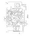
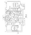
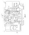
- FIGS. 4-7are vertical elevation cross sectional views of the two-pole circuit breaker of FIG. 1 in on, tripped, off and reset positions, respectively.
- numbershall mean one or an integer greater than one (i.e., a plurality).
- the disclosed conceptis described in association with a two-pole circuit breaker, although the disclosed concept is applicable to a wide range of two-pole electrical switching apparatus.
- an electrical switching apparatussuch as a two-pole circuit interrupter, a main (two-pole) circuit breaker, or a two-pole circuit breaker 2 is shown.
- the example two-pole circuit breaker 2includes a single external operating handle 4 .
- the disclosed conceptemploys a centered main style of operating handle 4 , while hiding the fact that it is a dual mechanism device and providing a more robust, main circuit breaker appearance.
- the example circuit breaker 2includes an enclosure 6 having an opening 8 .
- the example single external operating handle 4is disposed through the enclosure opening 8 .
- First and second poles 10 , 12are disposed in the enclosure 6 .
- the first pole 10is shown in FIGS. 4-7 .
- the second pole 12is essentially identical to the first pole 10 and is parallel to the first pole 10 , but is hidden in FIGS. 4-7 .
- the single external operating handle 4is centered between the first and second poles 10 , 12 .
- the enclosure 6includes six sides 14 , 16 , 18 , 20 , 22 , 24 .
- the example opening 8is centrally located on the side 14 .
- the first pole 10is proximate side 18 and the second pole 12 is proximate opposite side 22 .
- the operating handle 4includes a first projection 30 within the enclosure 6 cooperating with the first internal operating member 26 to open and close first separable contacts 32 (FIGS. 1 and 4 - 7 ), and a second projection 34 within the enclosure 6 cooperating with the second operating member 28 to open and close second separable contacts 36 ( FIG. 1 ).
- the first projection 30includes a first tapered channel 38 therein
- the first internal operating member 26includes a first tapered member 39 engaging ( FIG. 3 ) the first projection 30 at the first tapered channel 38
- the second projection 34includes a second tapered channel 40 therein
- the second internal operating member 28includes a second tapered member 41 engaging ( FIGS. 2 and 3 ) the second projection 34 at the second tapered channel 40 .
- the tapers of the channels 38 , 40 and the members 39 , 41are best shown in FIG. 3 .
- the two individual internal operating members 26 , 28are employed, one for each of the two parallel poles 10 , 12 , respectively, with the tapered members 39 , 41 on the top (with respect to FIGS. 2 and 3 ), in order that they can be slid into the respective channels 38 , 40 .
- the first projection 30can be a first tapered member (not shown)
- the second projection 34can be a second tapered member (not shown)
- the first internal operating member 26can include a first tapered channel (not shown) for mating with the first tapered member (not shown)
- the second internal operating member 28can include a second tapered channel (not shown) for mating with the second tapered member (not shown).
- a raised portion 42 on the top (with respect to FIG. 1 ) side 14 of the circuit breaker 2can be employed to clear a radius portion 44 ( FIGS. 2 and 3 ) of the main centered single external operating handle 4 .
- a radius portion 44FIGS. 2 and 3
- the top (with respect to FIG. 1 ) side 14 of the circuit breaker 2includes a side portion 45 and the raised portion 42 extending beyond the side portion 45 .
- the single external operating handle 4includes a handle portion 46 extending external to the enclosure 6 , an arcuate portion 48 coupled to the handle portion 46 within the enclosure 6 and being partially visible through the enclosure opening 8 , and an internal portion 50 entirely within the enclosure 6 and being coupled to the first and second projections 30 , 34 within the enclosure 6 .
- FIGS. 4-7show the two-pole circuit breaker 2 of FIG. 1 in on, tripped, off and reset positions, respectively.
- the single external operating handle 4has an on position with respect to the enclosure 6 .
- Each of the first and second internal operating members 26 (shown in FIGS. 2-7 ) and 28 (shown in FIGS. 2 and 3 )has an on position corresponding the on position of the single external operating handle 4 .
- FIGS. 5-7respectively show the tripped, off and reset positions of the single external operating handle 4 and the corresponding respective tripped, off and reset positions of the first and second internal operating members 26 , 28 .
- the first pole 10includes the first separable contacts 32 , a first operating mechanism 52 structured to open and close the first separable contacts 32 , and the first internal operating member 26 cooperating with the first operating mechanism 52 to open and close the first separable contacts 32 .
- the second pole 12( FIG. 1 ) includes the second separable contacts 36 , which are electrically independent of the first separable contacts 32 , a second operating mechanism 54 structured to open and close the second separable contacts 36 , and the second internal operating member 28 ( FIGS. 2 and 3 ) cooperating with the second operating mechanism 54 to open and close the second separable contacts 36 .
- each of the first and second poles 10 , 12further includes a trip mechanism 56 cooperating with a corresponding one of the first and second operating mechanisms 52 , 54 to trip open the respective first and second separable contacts 32 , 36 .
- FIGS. 6 and 7The off and reset positions of FIGS. 6 and 7 almost look exactly the same except in the reset position, the single external operating handle 4 is a little more rotated (clockwise with respect to FIG. 7 ) which makes the bottom 58 ( FIGS. 2 , 3 and 7 ) of the internal operating member 26 hit a projection 60 on a cradle 62 to make the cradle 62 rotate a little, lifting it off a latch surface 64 on armature 66 .
- the example circuit breaker 2includes conventional internal and external structures for each of the two poles 10 , 12 .
- these structuresinclude a line terminal 68 , a load terminal 70 , a fixed contact 72 , a movable contact 74 , a movable arm 76 , a bimetal 78 , a magnetic trip circuit/armature 80 including the armature 66 and its latch surface 64 , and the cradle 62 .
- the current path through the circuit breaker 2passes from the line terminal 68 to the fixed contact 72 , to the movable contact 74 when the first separable contacts 32 are closed, to the movable arm 76 , through first flexible shunt 77 to the bimetal 78 , and through the bimetal 78 and second flexible shunt 79 to the load terminal 70 .
- the disclosed conceptemploys a single centered main style of operating handle 4 , while hiding the fact that it is a dual pole device, and providing a relatively more robust, main circuit breaker appearance.
Landscapes
- Breakers (AREA)
- Tumbler Switches (AREA)
Abstract
Description
Claims (12)
Priority Applications (4)
| Application Number | Priority Date | Filing Date | Title |
|---|---|---|---|
| US13/313,104US8686304B2 (en) | 2011-12-07 | 2011-12-07 | Electrical switching apparatus including two poles and a single operating handle |
| CA2796916ACA2796916C (en) | 2011-12-07 | 2012-11-27 | Electrical switching apparatus including two poles and a single operating handle |
| CR20120615ACR20120615A (en) | 2011-12-07 | 2012-12-06 | ELECTRICAL SWITCHING DEVICE INCLUDING TWO POLES AND ONE SINGLE OPERATING HANDLE |
| MX2012014287AMX2012014287A (en) | 2011-12-07 | 2012-12-06 | Electrical switching apparatus including two poles and a single operating handle. |
Applications Claiming Priority (1)
| Application Number | Priority Date | Filing Date | Title |
|---|---|---|---|
| US13/313,104US8686304B2 (en) | 2011-12-07 | 2011-12-07 | Electrical switching apparatus including two poles and a single operating handle |
Publications (2)
| Publication Number | Publication Date |
|---|---|
| US20130146428A1 US20130146428A1 (en) | 2013-06-13 |
| US8686304B2true US8686304B2 (en) | 2014-04-01 |
Family
ID=48570523
Family Applications (1)
| Application Number | Title | Priority Date | Filing Date |
|---|---|---|---|
| US13/313,104Active2032-07-25US8686304B2 (en) | 2011-12-07 | 2011-12-07 | Electrical switching apparatus including two poles and a single operating handle |
Country Status (4)
| Country | Link |
|---|---|
| US (1) | US8686304B2 (en) |
| CA (1) | CA2796916C (en) |
| CR (1) | CR20120615A (en) |
| MX (1) | MX2012014287A (en) |
Families Citing this family (2)
| Publication number | Priority date | Publication date | Assignee | Title |
|---|---|---|---|---|
| US9620303B2 (en) | 2014-08-13 | 2017-04-11 | Eaton Corporation | Circuit breakers with handle bearing pins |
| US9412548B2 (en)* | 2014-08-13 | 2016-08-09 | Eaton Corporation | Circuit breakers with handle bearing sleeves |
Citations (14)
| Publication number | Priority date | Publication date | Assignee | Title |
|---|---|---|---|---|
| US2913542A (en)* | 1957-10-23 | 1959-11-17 | Ite Circuit Breaker Ltd | Two pole circuit breaker |
| US3959752A (en) | 1975-03-04 | 1976-05-25 | I-T-E Imperial Corporation | Narrow multi-pole circuit breaker having bodily movable instantaneous trip structure |
| US4077024A (en) | 1976-07-22 | 1978-02-28 | Heinemann Electric Company | Multi-pole circuit breaker |
| US4906958A (en) | 1988-11-02 | 1990-03-06 | Square D Company | Snap-on floating handle tie for multi-pole circuit breakers |
| US5043687A (en) | 1990-09-17 | 1991-08-27 | Westinghouse Electric Corp. | Adjustable walking beam interlock mechanism |
| US5453723A (en) | 1994-06-23 | 1995-09-26 | Eaton Corporation | Two-pole compartmentalized ground fault miniature circuit breaker with increased current rating |
| US5483211A (en) | 1994-06-23 | 1996-01-09 | Eaton Corporation | Two-pole compartmentalized ground fault miniature circuit breaker with a single central electronics compartment |
| US6239676B1 (en) | 2000-08-28 | 2001-05-29 | Eaton Corporation | Two pole circuit breaker calibrated in assembled state |
| US6369340B1 (en)* | 2000-03-10 | 2002-04-09 | General Electric Company | Circuit breaker mechanism for a contact system |
| US6614334B1 (en) | 2002-06-27 | 2003-09-02 | Eaton Corporation | Circuit breaker including two circuit breaker mechanisms and an operating handle |
| US6700467B2 (en)* | 2000-03-01 | 2004-03-02 | General Electric Company | Circuit interrupter operating mechanism |
| US6737594B2 (en)* | 2002-10-21 | 2004-05-18 | Eaton Corporation | Locking attachment for an electrical switching apparatus |
| US20110132733A1 (en)* | 2009-12-04 | 2011-06-09 | Ls Industrial Systems Co., Ltd. | Rotation pin correction mechanism for four poles mold cased circuit breaker |
| US20120145520A1 (en)* | 2010-12-13 | 2012-06-14 | Schneider Electric Industries Sas | Switchgear Device Having Several Single-Pole Switching Units and Comprising a Single Actuating Mechanism of Said Units |
- 2011
- 2011-12-07USUS13/313,104patent/US8686304B2/enactiveActive
- 2012
- 2012-11-27CACA2796916Apatent/CA2796916C/enactiveActive
- 2012-12-06MXMX2012014287Apatent/MX2012014287A/enunknown
- 2012-12-06CRCR20120615Apatent/CR20120615A/enunknown
Patent Citations (14)
| Publication number | Priority date | Publication date | Assignee | Title |
|---|---|---|---|---|
| US2913542A (en)* | 1957-10-23 | 1959-11-17 | Ite Circuit Breaker Ltd | Two pole circuit breaker |
| US3959752A (en) | 1975-03-04 | 1976-05-25 | I-T-E Imperial Corporation | Narrow multi-pole circuit breaker having bodily movable instantaneous trip structure |
| US4077024A (en) | 1976-07-22 | 1978-02-28 | Heinemann Electric Company | Multi-pole circuit breaker |
| US4906958A (en) | 1988-11-02 | 1990-03-06 | Square D Company | Snap-on floating handle tie for multi-pole circuit breakers |
| US5043687A (en) | 1990-09-17 | 1991-08-27 | Westinghouse Electric Corp. | Adjustable walking beam interlock mechanism |
| US5483211A (en) | 1994-06-23 | 1996-01-09 | Eaton Corporation | Two-pole compartmentalized ground fault miniature circuit breaker with a single central electronics compartment |
| US5453723A (en) | 1994-06-23 | 1995-09-26 | Eaton Corporation | Two-pole compartmentalized ground fault miniature circuit breaker with increased current rating |
| US6700467B2 (en)* | 2000-03-01 | 2004-03-02 | General Electric Company | Circuit interrupter operating mechanism |
| US6369340B1 (en)* | 2000-03-10 | 2002-04-09 | General Electric Company | Circuit breaker mechanism for a contact system |
| US6239676B1 (en) | 2000-08-28 | 2001-05-29 | Eaton Corporation | Two pole circuit breaker calibrated in assembled state |
| US6614334B1 (en) | 2002-06-27 | 2003-09-02 | Eaton Corporation | Circuit breaker including two circuit breaker mechanisms and an operating handle |
| US6737594B2 (en)* | 2002-10-21 | 2004-05-18 | Eaton Corporation | Locking attachment for an electrical switching apparatus |
| US20110132733A1 (en)* | 2009-12-04 | 2011-06-09 | Ls Industrial Systems Co., Ltd. | Rotation pin correction mechanism for four poles mold cased circuit breaker |
| US20120145520A1 (en)* | 2010-12-13 | 2012-06-14 | Schneider Electric Industries Sas | Switchgear Device Having Several Single-Pole Switching Units and Comprising a Single Actuating Mechanism of Said Units |
Also Published As
| Publication number | Publication date |
|---|---|
| CA2796916A1 (en) | 2013-06-07 |
| CA2796916C (en) | 2019-07-16 |
| CR20120615A (en) | 2013-05-15 |
| US20130146428A1 (en) | 2013-06-13 |
| MX2012014287A (en) | 2017-08-24 |
Similar Documents
| Publication | Publication Date | Title |
|---|---|---|
| US7646269B2 (en) | Electrical switching apparatus, and conductor assembly and shunt assembly therefor | |
| US10236150B2 (en) | Molded-case circuit breaker for DC | |
| US8853586B2 (en) | Electrical switching apparatus including magnet assembly and first and second arc chambers | |
| KR101968181B1 (en) | Low-voltage circuit breaker with residual current tripping device | |
| US10249464B2 (en) | Modular circuit breaker and method of assembling | |
| US6750743B1 (en) | Integrated thermal and magnetic trip unit | |
| US6175288B1 (en) | Supplemental trip unit for rotary circuit interrupters | |
| JP4325749B2 (en) | Circuit breaker with modular contact system for different frame sizes | |
| US6614334B1 (en) | Circuit breaker including two circuit breaker mechanisms and an operating handle | |
| CN102549701B (en) | The electric switch equipment of multipole | |
| CN104040671B (en) | Electrical switchgear and its unbutton latch assembly | |
| EP1399940B1 (en) | Miniature circuit breaker pole | |
| WO2012119555A1 (en) | Circuit breaker for optimizing space allocation | |
| US8686304B2 (en) | Electrical switching apparatus including two poles and a single operating handle | |
| CN209859890U (en) | Tripping mechanism of circuit breaker | |
| US7323956B1 (en) | Electrical switching apparatus and trip unit including one or more fuses | |
| US6842096B2 (en) | Circuit breaker magnetic trip assembly | |
| US9053888B2 (en) | Tie bar for molded case circuit breaker and method of assembly | |
| CN204792660U (en) | Circuit breaker | |
| CN204966436U (en) | Circuit breaker | |
| US7358455B2 (en) | Cradle stop assembly, and operating mechanism and electrical switching apparatus employing the same | |
| US6225884B1 (en) | Circuit breaker with mechanical trip load terminal/magnet barrier | |
| AU2002212566B2 (en) | Circuit breaker with bypass for redirecting high transient current and associated method | |
| CN222421849U (en) | Circuit breaker | |
| CN108899259A (en) | Earth leakage circuit breaker |
Legal Events
| Date | Code | Title | Description |
|---|---|---|---|
| AS | Assignment | Owner name:EATON CORPORATION, OHIO Free format text:ASSIGNMENT OF ASSIGNORS INTEREST;ASSIGNOR:MALONEY, JAMES G.;REEL/FRAME:027336/0741 Effective date:20111207 | |
| STCF | Information on status: patent grant | Free format text:PATENTED CASE | |
| MAFP | Maintenance fee payment | Free format text:PAYMENT OF MAINTENANCE FEE, 4TH YEAR, LARGE ENTITY (ORIGINAL EVENT CODE: M1551) Year of fee payment:4 | |
| AS | Assignment | Owner name:EATON INTELLIGENT POWER LIMITED, IRELAND Free format text:ASSIGNMENT OF ASSIGNORS INTEREST;ASSIGNOR:EATON CORPORATION;REEL/FRAME:048855/0626 Effective date:20171231 | |
| MAFP | Maintenance fee payment | Free format text:PAYMENT OF MAINTENANCE FEE, 8TH YEAR, LARGE ENTITY (ORIGINAL EVENT CODE: M1552); ENTITY STATUS OF PATENT OWNER: LARGE ENTITY Year of fee payment:8 | |
| MAFP | Maintenance fee payment | Free format text:PAYMENT OF MAINTENANCE FEE, 12TH YEAR, LARGE ENTITY (ORIGINAL EVENT CODE: M1553); ENTITY STATUS OF PATENT OWNER: LARGE ENTITY Year of fee payment:12 |