US8685792B2 - Integrated circuit package system with interposer - Google Patents
Integrated circuit package system with interposerDownload PDFInfo
- Publication number
- US8685792B2 US8685792B2US12/040,558US4055808AUS8685792B2US 8685792 B2US8685792 B2US 8685792B2US 4055808 AUS4055808 AUS 4055808AUS 8685792 B2US8685792 B2US 8685792B2
- Authority
- US
- United States
- Prior art keywords
- interposer
- integrated circuit
- cavity
- over
- circuit package
- Prior art date
- Legal status (The legal status is an assumption and is not a legal conclusion. Google has not performed a legal analysis and makes no representation as to the accuracy of the status listed.)
- Active, expires
Links
Images


Classifications
- H—ELECTRICITY
- H01—ELECTRIC ELEMENTS
- H01L—SEMICONDUCTOR DEVICES NOT COVERED BY CLASS H10
- H01L23/00—Details of semiconductor or other solid state devices
- H01L23/12—Mountings, e.g. non-detachable insulating substrates
- H—ELECTRICITY
- H01—ELECTRIC ELEMENTS
- H01L—SEMICONDUCTOR DEVICES NOT COVERED BY CLASS H10
- H01L25/00—Assemblies consisting of a plurality of semiconductor or other solid state devices
- H01L25/03—Assemblies consisting of a plurality of semiconductor or other solid state devices all the devices being of a type provided for in a single subclass of subclasses H10B, H10D, H10F, H10H, H10K or H10N, e.g. assemblies of rectifier diodes
- H01L25/10—Assemblies consisting of a plurality of semiconductor or other solid state devices all the devices being of a type provided for in a single subclass of subclasses H10B, H10D, H10F, H10H, H10K or H10N, e.g. assemblies of rectifier diodes the devices having separate containers
- H01L25/105—Assemblies consisting of a plurality of semiconductor or other solid state devices all the devices being of a type provided for in a single subclass of subclasses H10B, H10D, H10F, H10H, H10K or H10N, e.g. assemblies of rectifier diodes the devices having separate containers the devices being integrated devices of class H10
- H—ELECTRICITY
- H01—ELECTRIC ELEMENTS
- H01L—SEMICONDUCTOR DEVICES NOT COVERED BY CLASS H10
- H01L24/00—Arrangements for connecting or disconnecting semiconductor or solid-state bodies; Methods or apparatus related thereto
- H01L24/73—Means for bonding being of different types provided for in two or more of groups H01L24/10, H01L24/18, H01L24/26, H01L24/34, H01L24/42, H01L24/50, H01L24/63, H01L24/71
- H—ELECTRICITY
- H01—ELECTRIC ELEMENTS
- H01L—SEMICONDUCTOR DEVICES NOT COVERED BY CLASS H10
- H01L25/00—Assemblies consisting of a plurality of semiconductor or other solid state devices
- H01L25/03—Assemblies consisting of a plurality of semiconductor or other solid state devices all the devices being of a type provided for in a single subclass of subclasses H10B, H10D, H10F, H10H, H10K or H10N, e.g. assemblies of rectifier diodes
- H—ELECTRICITY
- H01—ELECTRIC ELEMENTS
- H01L—SEMICONDUCTOR DEVICES NOT COVERED BY CLASS H10
- H01L25/00—Assemblies consisting of a plurality of semiconductor or other solid state devices
- H01L25/16—Assemblies consisting of a plurality of semiconductor or other solid state devices the devices being of types provided for in two or more different subclasses of H10B, H10D, H10F, H10H, H10K or H10N, e.g. forming hybrid circuits
- H—ELECTRICITY
- H01—ELECTRIC ELEMENTS
- H01L—SEMICONDUCTOR DEVICES NOT COVERED BY CLASS H10
- H01L2224/00—Indexing scheme for arrangements for connecting or disconnecting semiconductor or solid-state bodies and methods related thereto as covered by H01L24/00
- H01L2224/01—Means for bonding being attached to, or being formed on, the surface to be connected, e.g. chip-to-package, die-attach, "first-level" interconnects; Manufacturing methods related thereto
- H01L2224/10—Bump connectors; Manufacturing methods related thereto
- H01L2224/15—Structure, shape, material or disposition of the bump connectors after the connecting process
- H01L2224/16—Structure, shape, material or disposition of the bump connectors after the connecting process of an individual bump connector
- H01L2224/161—Disposition
- H01L2224/16151—Disposition the bump connector connecting between a semiconductor or solid-state body and an item not being a semiconductor or solid-state body, e.g. chip-to-substrate, chip-to-passive
- H01L2224/16221—Disposition the bump connector connecting between a semiconductor or solid-state body and an item not being a semiconductor or solid-state body, e.g. chip-to-substrate, chip-to-passive the body and the item being stacked
- H01L2224/16225—Disposition the bump connector connecting between a semiconductor or solid-state body and an item not being a semiconductor or solid-state body, e.g. chip-to-substrate, chip-to-passive the body and the item being stacked the item being non-metallic, e.g. insulating substrate with or without metallisation
- H01L2224/16227—Disposition the bump connector connecting between a semiconductor or solid-state body and an item not being a semiconductor or solid-state body, e.g. chip-to-substrate, chip-to-passive the body and the item being stacked the item being non-metallic, e.g. insulating substrate with or without metallisation the bump connector connecting to a bond pad of the item
- H—ELECTRICITY
- H01—ELECTRIC ELEMENTS
- H01L—SEMICONDUCTOR DEVICES NOT COVERED BY CLASS H10
- H01L2224/00—Indexing scheme for arrangements for connecting or disconnecting semiconductor or solid-state bodies and methods related thereto as covered by H01L24/00
- H01L2224/01—Means for bonding being attached to, or being formed on, the surface to be connected, e.g. chip-to-package, die-attach, "first-level" interconnects; Manufacturing methods related thereto
- H01L2224/26—Layer connectors, e.g. plate connectors, solder or adhesive layers; Manufacturing methods related thereto
- H01L2224/31—Structure, shape, material or disposition of the layer connectors after the connecting process
- H01L2224/32—Structure, shape, material or disposition of the layer connectors after the connecting process of an individual layer connector
- H01L2224/321—Disposition
- H01L2224/32151—Disposition the layer connector connecting between a semiconductor or solid-state body and an item not being a semiconductor or solid-state body, e.g. chip-to-substrate, chip-to-passive
- H01L2224/32221—Disposition the layer connector connecting between a semiconductor or solid-state body and an item not being a semiconductor or solid-state body, e.g. chip-to-substrate, chip-to-passive the body and the item being stacked
- H01L2224/32225—Disposition the layer connector connecting between a semiconductor or solid-state body and an item not being a semiconductor or solid-state body, e.g. chip-to-substrate, chip-to-passive the body and the item being stacked the item being non-metallic, e.g. insulating substrate with or without metallisation
- H—ELECTRICITY
- H01—ELECTRIC ELEMENTS
- H01L—SEMICONDUCTOR DEVICES NOT COVERED BY CLASS H10
- H01L2224/00—Indexing scheme for arrangements for connecting or disconnecting semiconductor or solid-state bodies and methods related thereto as covered by H01L24/00
- H01L2224/01—Means for bonding being attached to, or being formed on, the surface to be connected, e.g. chip-to-package, die-attach, "first-level" interconnects; Manufacturing methods related thereto
- H01L2224/42—Wire connectors; Manufacturing methods related thereto
- H01L2224/47—Structure, shape, material or disposition of the wire connectors after the connecting process
- H01L2224/48—Structure, shape, material or disposition of the wire connectors after the connecting process of an individual wire connector
- H01L2224/481—Disposition
- H01L2224/48151—Connecting between a semiconductor or solid-state body and an item not being a semiconductor or solid-state body, e.g. chip-to-substrate, chip-to-passive
- H01L2224/48221—Connecting between a semiconductor or solid-state body and an item not being a semiconductor or solid-state body, e.g. chip-to-substrate, chip-to-passive the body and the item being stacked
- H01L2224/48225—Connecting between a semiconductor or solid-state body and an item not being a semiconductor or solid-state body, e.g. chip-to-substrate, chip-to-passive the body and the item being stacked the item being non-metallic, e.g. insulating substrate with or without metallisation
- H01L2224/48227—Connecting between a semiconductor or solid-state body and an item not being a semiconductor or solid-state body, e.g. chip-to-substrate, chip-to-passive the body and the item being stacked the item being non-metallic, e.g. insulating substrate with or without metallisation connecting the wire to a bond pad of the item
- H—ELECTRICITY
- H01—ELECTRIC ELEMENTS
- H01L—SEMICONDUCTOR DEVICES NOT COVERED BY CLASS H10
- H01L2224/00—Indexing scheme for arrangements for connecting or disconnecting semiconductor or solid-state bodies and methods related thereto as covered by H01L24/00
- H01L2224/01—Means for bonding being attached to, or being formed on, the surface to be connected, e.g. chip-to-package, die-attach, "first-level" interconnects; Manufacturing methods related thereto
- H01L2224/42—Wire connectors; Manufacturing methods related thereto
- H01L2224/47—Structure, shape, material or disposition of the wire connectors after the connecting process
- H01L2224/48—Structure, shape, material or disposition of the wire connectors after the connecting process of an individual wire connector
- H01L2224/481—Disposition
- H01L2224/48151—Connecting between a semiconductor or solid-state body and an item not being a semiconductor or solid-state body, e.g. chip-to-substrate, chip-to-passive
- H01L2224/48221—Connecting between a semiconductor or solid-state body and an item not being a semiconductor or solid-state body, e.g. chip-to-substrate, chip-to-passive the body and the item being stacked
- H01L2224/48225—Connecting between a semiconductor or solid-state body and an item not being a semiconductor or solid-state body, e.g. chip-to-substrate, chip-to-passive the body and the item being stacked the item being non-metallic, e.g. insulating substrate with or without metallisation
- H01L2224/4824—Connecting between the body and an opposite side of the item with respect to the body
- H—ELECTRICITY
- H01—ELECTRIC ELEMENTS
- H01L—SEMICONDUCTOR DEVICES NOT COVERED BY CLASS H10
- H01L2224/00—Indexing scheme for arrangements for connecting or disconnecting semiconductor or solid-state bodies and methods related thereto as covered by H01L24/00
- H01L2224/73—Means for bonding being of different types provided for in two or more of groups H01L2224/10, H01L2224/18, H01L2224/26, H01L2224/34, H01L2224/42, H01L2224/50, H01L2224/63, H01L2224/71
- H01L2224/732—Location after the connecting process
- H01L2224/73201—Location after the connecting process on the same surface
- H01L2224/73203—Bump and layer connectors
- H01L2224/73204—Bump and layer connectors the bump connector being embedded into the layer connector
- H—ELECTRICITY
- H01—ELECTRIC ELEMENTS
- H01L—SEMICONDUCTOR DEVICES NOT COVERED BY CLASS H10
- H01L2224/00—Indexing scheme for arrangements for connecting or disconnecting semiconductor or solid-state bodies and methods related thereto as covered by H01L24/00
- H01L2224/73—Means for bonding being of different types provided for in two or more of groups H01L2224/10, H01L2224/18, H01L2224/26, H01L2224/34, H01L2224/42, H01L2224/50, H01L2224/63, H01L2224/71
- H01L2224/732—Location after the connecting process
- H01L2224/73201—Location after the connecting process on the same surface
- H01L2224/73215—Layer and wire connectors
- H—ELECTRICITY
- H01—ELECTRIC ELEMENTS
- H01L—SEMICONDUCTOR DEVICES NOT COVERED BY CLASS H10
- H01L2224/00—Indexing scheme for arrangements for connecting or disconnecting semiconductor or solid-state bodies and methods related thereto as covered by H01L24/00
- H01L2224/73—Means for bonding being of different types provided for in two or more of groups H01L2224/10, H01L2224/18, H01L2224/26, H01L2224/34, H01L2224/42, H01L2224/50, H01L2224/63, H01L2224/71
- H01L2224/732—Location after the connecting process
- H01L2224/73251—Location after the connecting process on different surfaces
- H01L2224/73265—Layer and wire connectors
- H—ELECTRICITY
- H01—ELECTRIC ELEMENTS
- H01L—SEMICONDUCTOR DEVICES NOT COVERED BY CLASS H10
- H01L2225/00—Details relating to assemblies covered by the group H01L25/00 but not provided for in its subgroups
- H01L2225/03—All the devices being of a type provided for in the same main group of the same subclass of class H10, e.g. assemblies of rectifier diodes
- H01L2225/10—All the devices being of a type provided for in the same main group of the same subclass of class H10, e.g. assemblies of rectifier diodes the devices having separate containers
- H01L2225/1005—All the devices being of a type provided for in the same main group of the same subclass of class H10, e.g. assemblies of rectifier diodes the devices having separate containers the devices being integrated devices of class H10
- H01L2225/1011—All the devices being of a type provided for in the same main group of the same subclass of class H10, e.g. assemblies of rectifier diodes the devices having separate containers the devices being integrated devices of class H10 the containers being in a stacked arrangement
- H01L2225/1017—All the devices being of a type provided for in the same main group of the same subclass of class H10, e.g. assemblies of rectifier diodes the devices having separate containers the devices being integrated devices of class H10 the containers being in a stacked arrangement the lowermost container comprising a device support
- H01L2225/1023—All the devices being of a type provided for in the same main group of the same subclass of class H10, e.g. assemblies of rectifier diodes the devices having separate containers the devices being integrated devices of class H10 the containers being in a stacked arrangement the lowermost container comprising a device support the support being an insulating substrate
- H—ELECTRICITY
- H01—ELECTRIC ELEMENTS
- H01L—SEMICONDUCTOR DEVICES NOT COVERED BY CLASS H10
- H01L2225/00—Details relating to assemblies covered by the group H01L25/00 but not provided for in its subgroups
- H01L2225/03—All the devices being of a type provided for in the same main group of the same subclass of class H10, e.g. assemblies of rectifier diodes
- H01L2225/10—All the devices being of a type provided for in the same main group of the same subclass of class H10, e.g. assemblies of rectifier diodes the devices having separate containers
- H01L2225/1005—All the devices being of a type provided for in the same main group of the same subclass of class H10, e.g. assemblies of rectifier diodes the devices having separate containers the devices being integrated devices of class H10
- H01L2225/1011—All the devices being of a type provided for in the same main group of the same subclass of class H10, e.g. assemblies of rectifier diodes the devices having separate containers the devices being integrated devices of class H10 the containers being in a stacked arrangement
- H01L2225/1041—Special adaptations for top connections of the lowermost container, e.g. redistribution layer, integral interposer
- H—ELECTRICITY
- H01—ELECTRIC ELEMENTS
- H01L—SEMICONDUCTOR DEVICES NOT COVERED BY CLASS H10
- H01L2225/00—Details relating to assemblies covered by the group H01L25/00 but not provided for in its subgroups
- H01L2225/03—All the devices being of a type provided for in the same main group of the same subclass of class H10, e.g. assemblies of rectifier diodes
- H01L2225/10—All the devices being of a type provided for in the same main group of the same subclass of class H10, e.g. assemblies of rectifier diodes the devices having separate containers
- H01L2225/1005—All the devices being of a type provided for in the same main group of the same subclass of class H10, e.g. assemblies of rectifier diodes the devices having separate containers the devices being integrated devices of class H10
- H01L2225/1011—All the devices being of a type provided for in the same main group of the same subclass of class H10, e.g. assemblies of rectifier diodes the devices having separate containers the devices being integrated devices of class H10 the containers being in a stacked arrangement
- H01L2225/1047—Details of electrical connections between containers
- H01L2225/1052—Wire or wire-like electrical connections
- H—ELECTRICITY
- H01—ELECTRIC ELEMENTS
- H01L—SEMICONDUCTOR DEVICES NOT COVERED BY CLASS H10
- H01L2225/00—Details relating to assemblies covered by the group H01L25/00 but not provided for in its subgroups
- H01L2225/03—All the devices being of a type provided for in the same main group of the same subclass of class H10, e.g. assemblies of rectifier diodes
- H01L2225/10—All the devices being of a type provided for in the same main group of the same subclass of class H10, e.g. assemblies of rectifier diodes the devices having separate containers
- H01L2225/1005—All the devices being of a type provided for in the same main group of the same subclass of class H10, e.g. assemblies of rectifier diodes the devices having separate containers the devices being integrated devices of class H10
- H01L2225/1011—All the devices being of a type provided for in the same main group of the same subclass of class H10, e.g. assemblies of rectifier diodes the devices having separate containers the devices being integrated devices of class H10 the containers being in a stacked arrangement
- H01L2225/1047—Details of electrical connections between containers
- H01L2225/1058—Bump or bump-like electrical connections, e.g. balls, pillars, posts
- H—ELECTRICITY
- H01—ELECTRIC ELEMENTS
- H01L—SEMICONDUCTOR DEVICES NOT COVERED BY CLASS H10
- H01L2225/00—Details relating to assemblies covered by the group H01L25/00 but not provided for in its subgroups
- H01L2225/03—All the devices being of a type provided for in the same main group of the same subclass of class H10, e.g. assemblies of rectifier diodes
- H01L2225/10—All the devices being of a type provided for in the same main group of the same subclass of class H10, e.g. assemblies of rectifier diodes the devices having separate containers
- H01L2225/1005—All the devices being of a type provided for in the same main group of the same subclass of class H10, e.g. assemblies of rectifier diodes the devices having separate containers the devices being integrated devices of class H10
- H01L2225/1011—All the devices being of a type provided for in the same main group of the same subclass of class H10, e.g. assemblies of rectifier diodes the devices having separate containers the devices being integrated devices of class H10 the containers being in a stacked arrangement
- H01L2225/1076—Shape of the containers
- H01L2225/1088—Arrangements to limit the height of the assembly
- H—ELECTRICITY
- H01—ELECTRIC ELEMENTS
- H01L—SEMICONDUCTOR DEVICES NOT COVERED BY CLASS H10
- H01L2924/00—Indexing scheme for arrangements or methods for connecting or disconnecting semiconductor or solid-state bodies as covered by H01L24/00
- H01L2924/10—Details of semiconductor or other solid state devices to be connected
- H01L2924/11—Device type
- H01L2924/14—Integrated circuits
- H—ELECTRICITY
- H01—ELECTRIC ELEMENTS
- H01L—SEMICONDUCTOR DEVICES NOT COVERED BY CLASS H10
- H01L2924/00—Indexing scheme for arrangements or methods for connecting or disconnecting semiconductor or solid-state bodies as covered by H01L24/00
- H01L2924/15—Details of package parts other than the semiconductor or other solid state devices to be connected
- H01L2924/151—Die mounting substrate
- H01L2924/153—Connection portion
- H01L2924/1531—Connection portion the connection portion being formed only on the surface of the substrate opposite to the die mounting surface
- H01L2924/15311—Connection portion the connection portion being formed only on the surface of the substrate opposite to the die mounting surface being a ball array, e.g. BGA
- H—ELECTRICITY
- H01—ELECTRIC ELEMENTS
- H01L—SEMICONDUCTOR DEVICES NOT COVERED BY CLASS H10
- H01L2924/00—Indexing scheme for arrangements or methods for connecting or disconnecting semiconductor or solid-state bodies as covered by H01L24/00
- H01L2924/15—Details of package parts other than the semiconductor or other solid state devices to be connected
- H01L2924/181—Encapsulation
- H01L2924/1815—Shape
- H—ELECTRICITY
- H01—ELECTRIC ELEMENTS
- H01L—SEMICONDUCTOR DEVICES NOT COVERED BY CLASS H10
- H01L2924/00—Indexing scheme for arrangements or methods for connecting or disconnecting semiconductor or solid-state bodies as covered by H01L24/00
- H01L2924/19—Details of hybrid assemblies other than the semiconductor or other solid state devices to be connected
- H01L2924/191—Disposition
- H01L2924/19101—Disposition of discrete passive components
- H01L2924/19105—Disposition of discrete passive components in a side-by-side arrangement on a common die mounting substrate
- H—ELECTRICITY
- H01—ELECTRIC ELEMENTS
- H01L—SEMICONDUCTOR DEVICES NOT COVERED BY CLASS H10
- H01L2924/00—Indexing scheme for arrangements or methods for connecting or disconnecting semiconductor or solid-state bodies as covered by H01L24/00
- H01L2924/19—Details of hybrid assemblies other than the semiconductor or other solid state devices to be connected
- H01L2924/191—Disposition
- H01L2924/19101—Disposition of discrete passive components
- H01L2924/19107—Disposition of discrete passive components off-chip wires
Definitions
- the present inventionrelates generally to an integrated circuit package system and more particularly to an integrated circuit package system with interposer.
- Electronic devicessuch as smart phones, personal digital assistants, location based devices, digital cameras, music players, computers, or transportation, have become an integral part of many daily activities. Key components of these electronic devices are integrated circuit devices. These tiny integrated circuits must perform during daily activities including a wide variety of environmental conditions as well as potentially damaging forces. Many and varied types of packaging, intended for protection, interconnection or mounting, have been developed for integrated circuit devices.
- Integrated circuit diesare conventionally enclosed in plastic packages that provide protection from hostile environments and enable electrical interconnection between the integrated circuit die and an underlying substrate such as a printed circuit board (PCB).
- the elements of such a packageinclude: a lead frame or substrate, an integrated circuit die, bonding material to attach the integrated circuit die to the lead frame or substrate, bond wires or other connectors that electrically connect pads on the integrated circuit die to the lead frame or substrate.
- the packagecan also include a plastic or other insulating material that covers the components and forms the exterior of the package.
- Wafer manufacturingstrives to reduce transistor or capacitor feature size in order to increase circuit density and enhance functionality.
- Device geometries with sub-micron line widthsare so common that individual chips routinely contain millions of electronic devices.
- Reduced feature sizehas been quite successful in improving electronic systems, and continuous development is expected in the future.
- significant obstacles to further reduction in feature sizeare being encountered. These obstacles include defect density control, optical system resolution limits, and availability of processing material and equipment. Attention has therefore increasingly shifted to semiconductor packaging as a means to fulfill the relentless demands for enhanced system performance.
- Drawbacks of conventional designsinclude a relatively large footprint of the package on the mounting surface of motherboard.
- the footprintreflects dimensions that are typically the maximum of the package, namely, the maximum x-y dimensions of the package.
- a large footprintis undesirable.
- manufacturershave been stacking two or more die within a single package. Unfortunately, sufficient overlap for electrical interconnect, large footprint top packages, increased device integration, pre-testing, and interconnect lengths have plagued previous package designs.
- An integrated circuit package systemincludes: providing a mountable integrated circuit system having an encapsulation with a cavity therein and a first interposer exposed by the cavity; mounting a second interposer over the first interposer for only stacking a discrete device thereover, and with the second interposer over the encapsulation and the cavity; and mounting an electrical component over the second interposer.
- FIG. 1is a bottom view of an integrated circuit package system in a first embodiment of the present invention
- FIG. 2is a cross-sectional view of the integrated circuit package system along line 2 - 2 of FIG. 1 ;
- FIG. 3is a cross-sectional view of an integrated circuit package system exemplified by the bottom view of FIG. 1 along line 2 - 2 of FIG. 1 in a second embodiment of the present invention
- FIG. 4is a cross-sectional view of an integrated circuit package system exemplified by the bottom view of FIG. 1 along line 2 - 2 of FIG. 1 in a third embodiment of the present invention
- FIG. 5is a cross-sectional view of an integrated circuit package system exemplified by the bottom view of FIG. 1 along line 2 - 2 of FIG. 1 in a fourth embodiment of the present invention
- FIG. 6is a cross-sectional view of an integrated circuit package system exemplified by the bottom view of FIG. 1 along line 2 - 2 of FIG. 1 in a fifth embodiment of the present invention
- FIG. 7is a cross-sectional view of an integrated circuit package system exemplified by the bottom view of FIG. 1 along line 2 - 2 of FIG. 1 in a sixth embodiment of the present invention
- FIG. 8is a cross-sectional view of an integrated circuit package system exemplified by the bottom view of FIG. 1 along line 2 - 2 of FIG. 1 in a seventh embodiment of the present invention
- FIG. 9is a cross-sectional view of an integrated circuit package system exemplified by the bottom view of FIG. 1 along line 2 - 2 of FIG. 1 in a eighth embodiment of the present invention.
- FIG. 10is a cross-sectional view of an integrated circuit package system exemplified by the bottom view of FIG. 1 along line 2 - 2 of FIG. 1 in a ninth embodiment of the present invention.
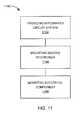
- FIG. 11is a flow chart of an integrated circuit package system for manufacturing of the integrated circuit package system in an embodiment of the present invention.
- the term “horizontal” as used hereinis defined as a plane parallel to the plane or surface of the integrated circuit, regardless of its orientation.
- the term “vertical”refers to a direction perpendicular to the horizontal as just defined. Terms, such as “above”, “below”, “bottom”, “top”, “side” (as in “sidewall”), “higher”, “lower”, “upper”, “over”, and “under”, are defined with respect to the horizontal plane.
- the term “on”means there is direct contact among elements.
- processingas used herein includes deposition of material, patterning, exposure, development, etching, cleaning, molding, and/or removal of the material or as required in forming a described structure.
- systemas used herein means and refers to the method and to the apparatus of the present invention in accordance with the context in which the term is used.
- FIG. 1therein is shown a bottom view of an integrated circuit package system 100 in a first embodiment of the present invention.
- the bottom viewdepicts a base substrate 102 , such as a laminated substrate, and external interconnects 104 , such as solder balls, attached to the base substrate 102 .
- the integrated circuit package system 100is shown with the external interconnects 104 equally spaced. Although, it is understood that the integrated circuit package system 100 may have some sites depopulated such that the integrated circuit package system 100 may have the external interconnects 104 not equally spaced.
- FIG. 2therein is shown a cross-sectional view of the integrated circuit package system 100 along line 2 - 2 of FIG. 1 .
- the cross-sectional viewdepicts a mountable integrated circuit system 206 having an encapsulation 208 , such as a cover comprising an epoxy molding compound, with a cavity 210 and having a first interposer 212 exposed by the cavity 210 .
- a second interposer 214such as a laminated substrate, mounts over the encapsulation 208 and the cavity 210 .
- the second interposer 214connects with the first interposer 212 .
- An electronic component 216such as a flip chip, is mounted over the second interposer 214 .
- the second interposer 214with the electronic component 216 thereover, is completely exposed from the encapsulation 208 or molding compound.
- An electrical attachment extent of the second interposer 214includes a horizontal length greater than a horizontal length of an exposed extent of the first interposer 212 .
- the electrical attachment extentis an area at a top side of the second interposer 214 for electrically attaching electrical components, including the electronic component 216 , to the second interposer 214 .
- the exposed extentis exposed from the encapsulation 208 .
- the second interposer 214has a side facing the cavity 210 and an opposite side having an electrical attachment area 217 directly over the cavity 210 .
- the mountable integrated circuit system 206includes an integrated circuit package 218 and passive devices 220 over the base substrate 102 , such as a laminated substrate.
- First internal interconnects 222such as bond wires or ribbon bond wires, connect the first interposer 212 of the integrated circuit package 218 and the base substrate 102 .
- the encapsulation 208is over the base substrate 102 covering the integrated circuit package 218 , the first internal interconnects 222 , and the passive devices 220 .
- the integrated circuit package 218includes an integrated circuit die 224 .
- the integrated circuit die 224includes a non-active side 226 and an active side 228 , wherein the active side 228 includes active circuitry fabricated thereon.
- the non-active side 226attaches with the first interposer 212 with an adhesive 230 , such as a die-attach adhesive.
- the first internal interconnects 222such as bond wires or ribbon bond wires, can connect the first interposer 212 of the integrated circuit package 218 and the base substrate 102 .
- the external interconnects 104can attach below and to the base substrate 102 for connection to the next system level (not shown), such as a printed circuit board or another integrated circuit package system.
- the second interposer 214includes electrical connectors 232 , such as solder balls. As an example, the second interposer 214 connects with the first interposer 212 with the electrical connectors 232 .
- the electronic component 216mounts over the second interposer 214 .
- the electronic componentmay be a Known Good Device (“KGD”) that has been functionally tested.
- KGDKnown Good Device
- the present inventionprovides an integrated circuit package on package system with reduced height by using the second interposer.
- the second interposeris configured to have redistribution layer and vias for bridging electrical connections between the integrated circuit below the second interposer and the electronic component above the second interposer.
- the second interposercan be pre-attached to either the integrated circuit system or the electronic component in order to have them tested before final assembly. This feature can further reduce manufacturing cost and increase reliability.
- FIG. 3therein is shown a cross-sectional view of an integrated circuit package system 300 along line 2 - 2 of FIG. 1 in a second embodiment of the present invention.
- the cross-sectional viewdepicts a mountable integrated circuit system 306 having an encapsulation 308 , such as a cover comprising an epoxy molding compound, with a cavity 310 and having a first interposer 312 exposed by the cavity 310 .
- a second interposer 314such as a laminated substrate, mounts over the encapsulation 308 and the cavity 310 .
- the second interposer 314connects with the first interposer 312 .
- An electronic component 316such as a flip chip, is mounted over the second interposer 314 .
- the mountable integrated circuit system 306includes an integrated circuit package 318 and passive devices 320 over a base substrate 302 , such as a laminated substrate.
- First internal interconnects 322such as bond wires or ribbon bond wires, connect the first interposer 312 of the integrated circuit package 318 and the base substrate 302 .
- the encapsulation 308is over the base substrate 302 covering the integrated circuit package 318 , the first internal interconnects 322 , and the passive devices 320 .
- the integrated circuit package 318can be a Wafer Level Chip Scale Package (WLCSP), a Redistributed Layer (RDL) die or a flip chip.
- the integrated circuit package 318includes the first interposer 312 .
- the integrated circuit package 318attaches to the base substrate 302 with an adhesive 330 , such as a die-attach adhesive.
- the first internal interconnects 322such as bond wires or ribbon bond wires, can connect the first interposer 312 and the base substrate 302 .
- External interconnects 304can attach below and to the base substrate 302 for connection to the next system level (not shown), such as a printed circuit board or another integrated circuit package system.
- the second interposer 314includes electrical connectors 332 , such as solder balls. As an example, the second interposer 314 connects with the first interposer 312 with the electrical connectors 332 .
- the electronic component 316mounts over the second interposer 314 .
- the electronic componentmay be a Known Good Device (“KGD”) that has been functionally tested.
- KGDKnown Good Device
- FIG. 4therein is shown a cross-sectional view of an integrated circuit package system 400 along line 2 - 2 of FIG. 1 in a third embodiment of the present invention.
- the cross-sectional viewdepicts a mountable integrated circuit system 406 having an encapsulation 408 , such as a cover comprising an epoxy molding compound, with a cavity 410 and having a first interposer 412 exposed by the cavity 410 .
- a second interposer 414such as a laminated substrate, mounts over the encapsulation 408 and the cavity 410 .
- the second interposer 414connects with the first interposer 412 .
- An electronic component 416such as a flip chip, is mounted over the second interposer 414 .
- the mountable integrated circuit system 406includes an integrated circuit package 418 and passive devices 420 over a base substrate 402 , such as a laminated substrate.
- First internal interconnects 422such as bond wires or ribbon bond wires, connect the first interposer 412 of the integrated circuit package 418 and the base substrate 402 .
- the encapsulation 408is over the base substrate 402 covering the integrated circuit package 418 , the first internal interconnects 422 , and the passive devices 420 .
- the integrated circuit package 418includes an integrated circuit die 424 .
- the integrated circuit die 424includes a non-active side 426 and an active side 428 , wherein the active side 428 includes active circuitry fabricated thereon.
- the non-active side 426attaches with the base substrate 402 with an adhesive 430 , such as a die-attach adhesive.
- Second internal interconnects 434such as bond wires or ribbon bond wires, can connect the active side 428 and the base substrate 402 .
- An inner encapsulation 436such as a cover comprising an epoxy molding compound, is over the base substrate 402 covering the integrated circuit die 424 and the second internal interconnects 434 .
- the first interposer 412mounts over the inner encapsulation 436 of the integrated circuit package 418 with a second adhesive 439 .
- the second interposer 414includes electrical connectors 432 , such as solder balls.
- the second interposer 414connects with the first interposer 412 with the electrical connectors 432 .
- the electronic component 416mounts over the second interposer 414 .
- External interconnects 404can attach below and to the base substrate 402 for connection to the next system level (not shown), such as a printed circuit board or another integrated circuit package system.
- FIG. 5therein is shown a cross-sectional view of an integrated circuit package system 500 along line 2 - 2 of FIG. 1 in a fourth embodiment of the present invention.
- the cross-sectional viewdepicts a mountable integrated circuit system 506 having an encapsulation 508 , such as a cover comprising an epoxy molding compound, with a cavity 510 and having a first interposer 512 exposed by the cavity 510 .
- a second interposer 514such as a laminated substrate, mounts over the encapsulation 508 and the cavity 510 .
- the second interposer 514connects with the first interposer 512 .
- An electronic component 516such as a flip chip, is mounted over the second interposer 514 .
- the mountable integrated circuit system 506includes a first integrated circuit package 518 , a second integrated circuit package 538 , and passive devices 520 over a base substrate 502 , such as a laminated substrate.
- the second integrated circuit package 538is over the first integrated circuit package 518 .
- First internal interconnects 522such as bond wires or ribbon bond wires, connect the first interposer 512 of the second integrated circuit package 538 and the base substrate 502 .
- the encapsulation 508is over the base substrate 502 covering the first integrated circuit package 518 , the second integrated circuit package 538 , the first internal interconnects 522 , and the passive devices 520 .
- the first integrated circuit package 518includes an integrated circuit die 524 .
- the integrated circuit die 524includes a first non-active side 526 and a first active side 528 , wherein the first active side 528 includes active circuitry fabricated thereon.
- the first non-active side 526attaches to the base substrate 502 with a first adhesive 530 , such as a die-attach adhesive.
- Second internal interconnects 534such as bond wires or ribbon bond wires, can connect the first active side 528 and the base substrate 502 .
- An inner encapsulation 536such as a cover comprising an epoxy molding compound, is over the base substrate 502 covering the integrated circuit die 524 and the second internal interconnects 534 .
- the second integrated circuit package 538mounts over the first integrated circuit package 518 with a second adhesive 539 .
- the second integrated circuit package 538includes a second integrated circuit die 540 .
- the second integrated circuit die 540includes a second non-active side 542 and a second active side 544 wherein the second active side 544 includes active circuitry fabricated thereon.
- the second non-active side 542attaches with the first interposer 512 with a third adhesive 546 .
- the second active side 544can connect with the first interposer 512 with third internal interconnects 548 .
- the second interposer 514includes electrical connectors 532 , such as solder balls. As an example, the second interposer 514 connects with the first interposer 512 with the electrical connectors 532 . External interconnects 504 can attach below and to the base substrate 502 for connection to the next system level (not shown), such as a printed circuit board or another integrated circuit package system.
- FIG. 6therein is shown a cross-sectional view of an integrated circuit package system 600 along line 2 - 2 of FIG. 1 in a fifth embodiment of the present invention.
- the cross-sectional viewdepicts a mountable integrated circuit system 606 having an encapsulation 608 , such as a cover comprising an epoxy molding compound, with a cavity 610 and having a first interposer 612 exposed by the cavity 610 .
- a second interposer 614such as a laminated substrate, mounts over the encapsulation 608 and the cavity 610 .
- the second interposer 614connects with the first interposer 612 .
- An electronic component 616such as a flip chip or a packaged integrated circuit device, is mounted over the second interposer 614 .
- the integrated circuit package system 600is shown with the electronic component as a single device, although it is understood that the integrated circuit package system 600 may have electronic components over the second interposer 614 in a different configuration.
- the electronic component 616may represent a number of components.
- the mountable integrated circuit system 606includes an integrated circuit package 618 and passive devices 620 over a base substrate 602 , such as a laminated substrate.
- First internal interconnects 622such as bond wires or ribbon bond wires, connect the first interposer 612 of the integrated circuit package 618 and the base substrate 602 .
- the encapsulation 608is over the base substrate 602 covering the integrated circuit package 618 , the first internal interconnects 622 , and the passive devices 620 .
- the integrated circuit package system 600is shown with the encapsulation 608 having vertical sidewalls over the top side of the base substrate 602 , although it is understood that the integrated circuit package system 600 may have a different configuration for the encapsulation 608 .
- the encapsulation 608can partially cover the top side of the base substrate 602 with non-vertical sidewalls.
- the integrated circuit package 618includes an integrated circuit die 624 .
- the integrated circuit die 624includes a non-active side 626 and an active side 628 , wherein the active side 628 includes active circuitry fabricated thereon.
- the non-active side 626attaches with the first interposer 612 with an adhesive 630 , such as a die-attach adhesive.
- Second internal interconnects 634such as bond wires or ribbon bond wires, can connect the active side 628 and the base substrate 602 .
- External interconnects 604can attach below and to the base substrate 602 for connection to the next system level (not shown), such as a printed circuit board or another integrated circuit package system.
- the second interposer 614includes electrical connectors 632 , such as solder balls.
- the second interposer 614connects with the first interposer 612 with the electrical connectors 632 .
- the second interposer 614extends the length of a top side of the encapsulation 608 and further passive devices 646 mount over or directly on the second interposer 614 .
- FIG. 7therein is shown a cross-sectional view of an integrated circuit package system 700 along line 2 - 2 of FIG. 1 in a sixth embodiment of the present invention.
- the cross-sectional viewdepicts a mountable integrated circuit system 706 having an encapsulation 708 , such as a cover comprising an epoxy molding compound, with a cavity 710 and having a first interposer 712 exposed by the cavity 710 .
- a second interposer 714such as a laminated substrate, mounts over the encapsulation 708 and the cavity 710 .
- the second interposer 714includes a slot 740 over the cavity 710 .
- the second interposer 714connects with the first interposer 712 .
- An electronic component 716such as a packaged integrated circuit device, is mounted over the second interposer 714 .
- the mountable integrated circuit system 706includes an integrated circuit package 718 and passive devices 720 over a base substrate 702 , such as a laminated substrate.
- First internal interconnects 722such as bond wires or ribbon bond wires, connect the first interposer 712 of the integrated circuit package 718 and the base substrate 702 .
- the encapsulation 708is over the base substrate 702 covering the integrated circuit package 718 , the first internal interconnects 722 , and the passive devices 720 .
- the integrated circuit package 718includes an integrated circuit die 724 .
- the integrated circuit die 724includes a non-active side 726 and an active side 728 , wherein the active side 728 includes active circuitry fabricated thereon.
- the non-active side 726attaches with the first interposer 712 with an adhesive 730 , such as a die-attach adhesive.
- Second internal interconnects 734such as bond wires or ribbon bond wires, can connect the active side 728 and the first interposer 712 .
- External interconnects 704can attach below and to the base substrate 702 for connection to the next system level (not shown), such as a printed circuit board or another integrated circuit package system.
- the second interposer 714includes electrical connectors 732 , such as solder balls. As an example, the second interposer 714 connects with the first interposer 712 with the electrical connectors 732 .
- An underfill 742surrounds the electrical connectors 732 , fills the cavity 710 , and surrounds component connectors 744 of the electronic component 716 .
- the underfill 742also fills the slot 740 .
- the slot 740can be used for flow of the underfill 742 .
- Further passive devices 746also mount over the second interposer 714 .
- FIG. 8therein is shown a cross-sectional view of an integrated circuit package system 800 along line 2 - 2 of FIG. 1 in a seventh embodiment of the present invention.
- the cross-sectional viewdepicts a mountable integrated circuit system 806 having an encapsulation 808 , such as a cover comprising an epoxy molding compound, with a cavity 810 and having a first interposer 812 exposed by the cavity 810 .
- a second interposer 814such as a laminated substrate, mounts over the encapsulation 808 and the cavity 810 .
- the second interposer 814includes a slot 840 over the cavity 810 and along a side wall of the cavity 810 .
- the second interposer 814connects with the first interposer 812 .
- An electronic component 816such as a flip chip, is mounted over the second interposer 814 .
- the mountable integrated circuit system 806includes an integrated circuit package 818 and passive devices 820 over a base substrate 802 , such as a laminated substrate.
- First internal interconnects 822such as bond wires or ribbon bond wires, connect the first interposer 812 of the integrated circuit package 818 and the base substrate 802 .
- the encapsulation 808is over the base substrate 802 covering the integrated circuit package 818 , the first internal interconnects 822 , and the passive devices 820 .
- the integrated circuit package 818includes an integrated circuit die 824 .
- the integrated circuit die 824includes a non-active side 826 and an active side 828 , wherein the active side 828 includes active circuitry fabricated thereon.
- the non-active side 826attaches with the first interposer 812 with an adhesive 830 , such as a die-attach adhesive.
- Second internal interconnects 834such as bond wires or ribbon bond wires, can connect the active side 828 and the first interposer 812 .
- External interconnects 804can attach below and to the base substrate 802 for connection to the next system level (not shown), such as a printed circuit board or another integrated circuit package system.
- the second interposer 814includes electrical connectors 832 , such as solder balls. As an example, the second interposer 814 connects with the first interposer 812 with the electrical connectors 832 .
- An underfill 842surrounds the electrical connectors 832 , fills the cavity 810 , and surrounds component connectors 844 of the electronic component 816 .
- the underfill 842includes low viscosity material such that it cannot be used as an encapsulation, such as the encapsulation 808 .
- the slot 840can be used for flow of the underfill 842 .
- Further passive devices 846also mount over the second interposer 814 .
- FIG. 9therein is shown a cross-sectional view of an integrated circuit package system 900 along line 2 - 2 of FIG. 1 in an eighth embodiment of the present invention.
- the cross-sectional viewdepicts a mountable integrated circuit system 906 having an encapsulation 908 , such as a cover comprising an epoxy molding compound, with a cavity 910 and having a first interposer 912 exposed by the cavity 910 .
- a second interposer 914such as a laminated substrate, mounts over the encapsulation 908 and the cavity 910 .
- the second interposer 914connects with the first interposer 912 .
- An electronic component 916such as a flip chip, is mounted over the second interposer 914 .
- the mountable integrated circuit system 906includes an integrated circuit package 918 and passive devices 920 over a base substrate 902 , such as a laminated substrate.
- First internal interconnects 922such as bond wires or ribbon bond wires, connect the first interposer 912 of the integrated circuit package 918 and the base substrate 902 .
- the integrated circuit package 918includes an integrated circuit die 924 .
- the integrated circuit die 924includes a non-active side 926 and an active side 928 , wherein the active side 928 includes active circuitry fabricated thereon.
- the non-active side 926attaches with a carrier 952 , such as a laminated substrate, with an adhesive 930 , such as a die-attach adhesive.
- the first interposer 912mounts over the integrated circuit package 918 and connects with the integrated circuit package 918 with internal connectors 948 , such as solder balls. Further passive devices 946 also mount to and below the first interposer 912 .
- the second interposer 914includes electrical connectors 932 , such as solder balls. As an example, the second interposer 914 connects with the first interposer 912 with the electrical connectors 932 .
- the second interposer 914can extend the length of a top side of the encapsulation 908 . Yet further passive devices 950 mounts over the second interposer 914 .
- the encapsulation 908is over the base substrate 902 covering the integrated circuit package 918 , the first internal interconnects 922 , the passive devices 920 , and the further passive devices 946 .
- External interconnects 904can attach below and to the base substrate 902 for connection to the next system level (not shown), such as a printed circuit board or another integrated circuit package system.
- FIG. 10therein is shown a cross-sectional view of an integrated circuit package system 1000 along line 2 - 2 of FIG. 1 in a ninth embodiment of the present invention.
- the cross-sectional viewdepicts a mountable integrated circuit system 1006 having an encapsulation 1008 , such as a cover comprising an epoxy molding compound, with a cavity 1010 and having a first interposer 1012 exposed by the cavity 1010 .
- an encapsulation 1008such as a cover comprising an epoxy molding compound
- a second interposer 1014mounts over the encapsulation 1008 with an adhesive 1030 and over the cavity 1010 .
- the second interposer 1014includes a slot 1040 over the cavity 1010 .
- An electronic component 1016is mounted over the second interposer 1014 .
- the mountable integrated circuit system 1006includes an integrated circuit package 1018 and passive devices 1020 over a base substrate 1002 , such as a laminated substrate.
- First internal interconnects 1022such as bond wires or ribbon bond wires, connect the first interposer 1012 of the integrated circuit package 1018 and the base substrate 1002 .
- Second internal interconnects 1034through the slot 1040 , connect the center bond pads of the first interposer 1012 and the second interposer 1014 .
- the encapsulation 1008such as cover comprising an epoxy molding compound, is over the base substrate 1002 covering the integrated circuit package 1018 , the first internal interconnects 1022 , and the passive devices 1020 .
- a cavity cover 1048such as a cover comprising a glob top material, fills the slot 1040 and the cavity 1010 covering the second internal interconnects 1034 .
- Further passive devices 1046also mount over the second interposer 1014 .
- External interconnects 1004can attach below and to the base substrate 1002 for connection to the next system level (not shown), such as a printed circuit board or another integrated circuit package system.
- the system 1100includes providing a mountable integrated circuit system having an encapsulation with a cavity therein and a first interposer exposed by the cavity in a block 1102 ; mounting a second interposer over the first interposer for only stacking a discrete device thereover, and with the second interposer over the encapsulation and the cavity in a block 1104 ; and mounting an electrical component over the second interposer in a block 1106 .
- Yet another important aspect of the present inventionis that it valuably supports and services the historical trend of reducing costs, simplifying systems, and increasing performance.
- the integrated circuit package system of the present inventionfurnishes important and heretofore unknown and unavailable solutions, capabilities, and functional aspects for improving yield, increasing reliability, and reducing cost of circuit system.
- the resulting processes and configurationsare straightforward, cost-effective, uncomplicated, highly versatile, accurate, sensitive, and effective, and can be implemented by adapting known components for ready, efficient, and economical manufacturing, application, and utilization.
Landscapes
- Engineering & Computer Science (AREA)
- Microelectronics & Electronic Packaging (AREA)
- Power Engineering (AREA)
- Computer Hardware Design (AREA)
- Physics & Mathematics (AREA)
- Condensed Matter Physics & Semiconductors (AREA)
- General Physics & Mathematics (AREA)
- Structures Or Materials For Encapsulating Or Coating Semiconductor Devices Or Solid State Devices (AREA)
Abstract
Description
Claims (10)
Priority Applications (2)
| Application Number | Priority Date | Filing Date | Title |
|---|---|---|---|
| US12/040,558US8685792B2 (en) | 2007-03-03 | 2008-02-29 | Integrated circuit package system with interposer |
| US12/056,402US9236319B2 (en) | 2008-02-29 | 2008-03-27 | Stacked integrated circuit package system |
Applications Claiming Priority (2)
| Application Number | Priority Date | Filing Date | Title |
|---|---|---|---|
| US89285107P | 2007-03-03 | 2007-03-03 | |
| US12/040,558US8685792B2 (en) | 2007-03-03 | 2008-02-29 | Integrated circuit package system with interposer |
Publications (2)
| Publication Number | Publication Date |
|---|---|
| US20080211084A1 US20080211084A1 (en) | 2008-09-04 |
| US8685792B2true US8685792B2 (en) | 2014-04-01 |
Family
ID=39732487
Family Applications (1)
| Application Number | Title | Priority Date | Filing Date |
|---|---|---|---|
| US12/040,558Active2028-09-03US8685792B2 (en) | 2007-03-03 | 2008-02-29 | Integrated circuit package system with interposer |
Country Status (3)
| Country | Link |
|---|---|
| US (1) | US8685792B2 (en) |
| KR (1) | KR101510412B1 (en) |
| TW (1) | TWI479642B (en) |
Cited By (29)
| Publication number | Priority date | Publication date | Assignee | Title |
|---|---|---|---|---|
| US20130320534A1 (en)* | 2011-03-22 | 2013-12-05 | Yujuan Tao | System-level packaging methods and structures |
| US20150137364A1 (en)* | 2005-08-19 | 2015-05-21 | Micron Technology, Inc. | Microelectronic devices, stacked microelectronic devices, and methods for manufacturing microelectronic devices |
| US20150235934A1 (en)* | 2012-01-13 | 2015-08-20 | Taiwan Semiconductor Manufacturing Company, Ltd. | Methods and Apparatus for Thinner Package on Package Structures |
| US20150359119A1 (en)* | 2013-02-22 | 2015-12-10 | Panasonic Corporation | Electronic component package |
| US20160293543A1 (en)* | 2015-03-31 | 2016-10-06 | Infineon Technologies Austria Ag | Compound Semiconductor Device Including a Multilevel Carrier |
| US9735084B2 (en) | 2014-12-11 | 2017-08-15 | Invensas Corporation | Bond via array for thermal conductivity |
| US9761554B2 (en) | 2015-05-07 | 2017-09-12 | Invensas Corporation | Ball bonding metal wire bond wires to metal pads |
| US9812402B2 (en) | 2015-10-12 | 2017-11-07 | Invensas Corporation | Wire bond wires for interference shielding |
| US9842745B2 (en) | 2012-02-17 | 2017-12-12 | Invensas Corporation | Heat spreading substrate with embedded interconnects |
| US9888579B2 (en) | 2015-03-05 | 2018-02-06 | Invensas Corporation | Pressing of wire bond wire tips to provide bent-over tips |
| US9911718B2 (en) | 2015-11-17 | 2018-03-06 | Invensas Corporation | ‘RDL-First’ packaged microelectronic device for a package-on-package device |
| US9935075B2 (en) | 2016-07-29 | 2018-04-03 | Invensas Corporation | Wire bonding method and apparatus for electromagnetic interference shielding |
| US9947641B2 (en) | 2014-05-30 | 2018-04-17 | Invensas Corporation | Wire bond support structure and microelectronic package including wire bonds therefrom |
| US9953931B1 (en)* | 2016-10-25 | 2018-04-24 | Advanced Semiconductor Engineering, Inc | Semiconductor device package and a method of manufacturing the same |
| US9984992B2 (en) | 2015-12-30 | 2018-05-29 | Invensas Corporation | Embedded wire bond wires for vertical integration with separate surface mount and wire bond mounting surfaces |
| US10008469B2 (en) | 2015-04-30 | 2018-06-26 | Invensas Corporation | Wafer-level packaging using wire bond wires in place of a redistribution layer |
| US10062661B2 (en) | 2011-05-03 | 2018-08-28 | Tessera, Inc. | Package-on-package assembly with wire bonds to encapsulation surface |
| US10170412B2 (en) | 2012-05-22 | 2019-01-01 | Invensas Corporation | Substrate-less stackable package with wire-bond interconnect |
| US10181457B2 (en) | 2015-10-26 | 2019-01-15 | Invensas Corporation | Microelectronic package for wafer-level chip scale packaging with fan-out |
| US10290613B2 (en) | 2013-11-22 | 2019-05-14 | Invensas Corporation | Multiple bond via arrays of different wire heights on a same substrate |
| US10299368B2 (en) | 2016-12-21 | 2019-05-21 | Invensas Corporation | Surface integrated waveguides and circuit structures therefor |
| US10381326B2 (en) | 2014-05-28 | 2019-08-13 | Invensas Corporation | Structure and method for integrated circuits packaging with increased density |
| US10490528B2 (en) | 2015-10-12 | 2019-11-26 | Invensas Corporation | Embedded wire bond wires |
| US10546844B2 (en) | 2015-11-26 | 2020-01-28 | Samsung Electronics Co., Ltd. | Stack package and method of manufacturing the stack package |
| US10741499B2 (en) | 2011-03-22 | 2020-08-11 | Tongfu Microelectronics Co., Ltd. | System-level packaging structures |
| US11189595B2 (en) | 2011-10-17 | 2021-11-30 | Invensas Corporation | Package-on-package assembly with wire bond vias |
| US11404338B2 (en) | 2014-01-17 | 2022-08-02 | Invensas Corporation | Fine pitch bva using reconstituted wafer with area array accessible for testing |
| US11735570B2 (en)* | 2018-04-04 | 2023-08-22 | Intel Corporation | Fan out packaging pop mechanical attach method |
| US11837581B2 (en)* | 2019-04-15 | 2023-12-05 | Samsung Electronics Co., Ltd. | Semiconductor package |
Families Citing this family (38)
| Publication number | Priority date | Publication date | Assignee | Title |
|---|---|---|---|---|
| KR101313391B1 (en) | 2004-11-03 | 2013-10-01 | 테세라, 인코포레이티드 | Stacked packaging improvements |
| US8058101B2 (en) | 2005-12-23 | 2011-11-15 | Tessera, Inc. | Microelectronic packages and methods therefor |
| US8110905B2 (en)* | 2007-12-17 | 2012-02-07 | Stats Chippac Ltd. | Integrated circuit packaging system with leadframe interposer and method of manufacture thereof |
| US9236319B2 (en)* | 2008-02-29 | 2016-01-12 | Stats Chippac Ltd. | Stacked integrated circuit package system |
| US7750454B2 (en)* | 2008-03-27 | 2010-07-06 | Stats Chippac Ltd. | Stacked integrated circuit package system |
| US9159708B2 (en)* | 2010-07-19 | 2015-10-13 | Tessera, Inc. | Stackable molded microelectronic packages with area array unit connectors |
| US8482111B2 (en) | 2010-07-19 | 2013-07-09 | Tessera, Inc. | Stackable molded microelectronic packages |
| KR101075241B1 (en) | 2010-11-15 | 2011-11-01 | 테세라, 인코포레이티드 | Microelectronic package with terminals in dielectric member |
| US20120146206A1 (en) | 2010-12-13 | 2012-06-14 | Tessera Research Llc | Pin attachment |
| US8618659B2 (en) | 2011-05-03 | 2013-12-31 | Tessera, Inc. | Package-on-package assembly with wire bonds to encapsulation surface |
| US8389329B2 (en)* | 2011-05-31 | 2013-03-05 | Stats Chippac Ltd. | Integrated circuit packaging system with package stacking and method of manufacture thereof |
| US8698297B2 (en) | 2011-09-23 | 2014-04-15 | Stats Chippac Ltd. | Integrated circuit packaging system with stack device |
| US8716065B2 (en)* | 2011-09-23 | 2014-05-06 | Stats Chippac Ltd. | Integrated circuit packaging system with encapsulation and method of manufacture thereof |
| US9349706B2 (en) | 2012-02-24 | 2016-05-24 | Invensas Corporation | Method for package-on-package assembly with wire bonds to encapsulation surface |
| US8372741B1 (en) | 2012-02-24 | 2013-02-12 | Invensas Corporation | Method for package-on-package assembly with wire bonds to encapsulation surface |
| US8703539B2 (en)* | 2012-06-29 | 2014-04-22 | Taiwan Semiconductor Manufacturing Company, Ltd. | Multiple die packaging interposer structure and method |
| US9391008B2 (en) | 2012-07-31 | 2016-07-12 | Invensas Corporation | Reconstituted wafer-level package DRAM |
| US9502390B2 (en) | 2012-08-03 | 2016-11-22 | Invensas Corporation | BVA interposer |
| US8975738B2 (en) | 2012-11-12 | 2015-03-10 | Invensas Corporation | Structure for microelectronic packaging with terminals on dielectric mass |
| US8878353B2 (en) | 2012-12-20 | 2014-11-04 | Invensas Corporation | Structure for microelectronic packaging with bond elements to encapsulation surface |
| US9136254B2 (en) | 2013-02-01 | 2015-09-15 | Invensas Corporation | Microelectronic package having wire bond vias and stiffening layer |
| US9023691B2 (en) | 2013-07-15 | 2015-05-05 | Invensas Corporation | Microelectronic assemblies with stack terminals coupled by connectors extending through encapsulation |
| US8883563B1 (en) | 2013-07-15 | 2014-11-11 | Invensas Corporation | Fabrication of microelectronic assemblies having stack terminals coupled by connectors extending through encapsulation |
| US9034696B2 (en) | 2013-07-15 | 2015-05-19 | Invensas Corporation | Microelectronic assemblies having reinforcing collars on connectors extending through encapsulation |
| US9167710B2 (en) | 2013-08-07 | 2015-10-20 | Invensas Corporation | Embedded packaging with preformed vias |
| US9685365B2 (en) | 2013-08-08 | 2017-06-20 | Invensas Corporation | Method of forming a wire bond having a free end |
| US20150076714A1 (en) | 2013-09-16 | 2015-03-19 | Invensas Corporation | Microelectronic element with bond elements to encapsulation surface |
| US9087815B2 (en) | 2013-11-12 | 2015-07-21 | Invensas Corporation | Off substrate kinking of bond wire |
| US9082753B2 (en) | 2013-11-12 | 2015-07-14 | Invensas Corporation | Severing bond wire by kinking and twisting |
| US9263394B2 (en) | 2013-11-22 | 2016-02-16 | Invensas Corporation | Multiple bond via arrays of different wire heights on a same substrate |
| US9379074B2 (en) | 2013-11-22 | 2016-06-28 | Invensas Corporation | Die stacks with one or more bond via arrays of wire bond wires and with one or more arrays of bump interconnects |
| US9214454B2 (en) | 2014-03-31 | 2015-12-15 | Invensas Corporation | Batch process fabrication of package-on-package microelectronic assemblies |
| US9646917B2 (en) | 2014-05-29 | 2017-05-09 | Invensas Corporation | Low CTE component with wire bond interconnects |
| US10332854B2 (en) | 2015-10-23 | 2019-06-25 | Invensas Corporation | Anchoring structure of fine pitch bva |
| US9659848B1 (en) | 2015-11-18 | 2017-05-23 | Invensas Corporation | Stiffened wires for offset BVA |
| US11676900B2 (en)* | 2015-12-22 | 2023-06-13 | Intel Corporation | Electronic assembly that includes a bridge |
| US11145621B2 (en)* | 2018-06-06 | 2021-10-12 | Advanced Semiconductor Engineering, Inc. | Semiconductor package device and method of manufacturing the same |
| US12009351B2 (en)* | 2021-11-12 | 2024-06-11 | Advanced Semiconductor Engineering, Inc. | Plurality of semiconductor devices between stacked substrates |
Citations (20)
| Publication number | Priority date | Publication date | Assignee | Title |
|---|---|---|---|---|
| JP2002158312A (en)* | 2000-11-17 | 2002-05-31 | Oki Electric Ind Co Ltd | Semiconductor package for three-dimensional mounting, its manufacturing method and semiconductor device |
| US6504241B1 (en) | 1998-10-15 | 2003-01-07 | Sony Corporation | Stackable semiconductor device and method for manufacturing the same |
| US6531338B2 (en) | 1998-08-28 | 2003-03-11 | Micron Technology, Inc. | Method of manufacturing a semiconductor structure having stacked semiconductor devices |
| US6603072B1 (en) | 2001-04-06 | 2003-08-05 | Amkor Technology, Inc. | Making leadframe semiconductor packages with stacked dies and interconnecting interposer |
| US6617193B1 (en) | 1997-04-30 | 2003-09-09 | Hitachi Chemical Company, Ltd. | Semiconductor device, semiconductor device substrate, and methods of fabricating the same |
| US6621155B1 (en)* | 1999-12-23 | 2003-09-16 | Rambus Inc. | Integrated circuit device having stacked dies and impedance balanced transmission lines |
| US6713860B2 (en)* | 2002-02-01 | 2004-03-30 | Intel Corporation | Electronic assembly and system with vertically connected capacitors |
| US20040145039A1 (en)* | 2003-01-23 | 2004-07-29 | St Assembly Test Services Ltd. | Stacked semiconductor packages and method for the fabrication thereof |
| US20050218528A1 (en)* | 2004-03-31 | 2005-10-06 | Beatty John J | Capillary underfill channel |
| US7049692B2 (en)* | 2003-03-11 | 2006-05-23 | Fujitsu Limited | Stacked semiconductor device |
| US20060220209A1 (en)* | 2005-03-31 | 2006-10-05 | Stats Chippac Ltd. | Semiconductor stacked package assembly having exposed substrate surfaces on upper and lower sides |
| US7141874B2 (en)* | 2003-05-14 | 2006-11-28 | Matsushita Electric Industrial Co., Ltd. | Electronic component packaging structure and method for producing the same |
| US20070045796A1 (en)* | 2005-08-19 | 2007-03-01 | Micron Technology, Inc. | Microelectronic devices, stacked microelectronic devices, and methods for manufacturing microelectronic devices |
| US7242081B1 (en)* | 2006-04-24 | 2007-07-10 | Advanced Semiconductor Engineering Inc. | Stacked package structure |
| US20070210432A1 (en)* | 2006-03-10 | 2007-09-13 | Stats Chippac Ltd. | Stacked integrated circuits package system with passive components |
| US7288835B2 (en) | 2006-03-17 | 2007-10-30 | Stats Chippac Ltd. | Integrated circuit package-in-package system |
| US20070278696A1 (en) | 2006-05-30 | 2007-12-06 | Yung-Li Lu | Stackable semiconductor package |
| US7364945B2 (en) | 2005-03-31 | 2008-04-29 | Stats Chippac Ltd. | Method of mounting an integrated circuit package in an encapsulant cavity |
| US7429787B2 (en) | 2005-03-31 | 2008-09-30 | Stats Chippac Ltd. | Semiconductor assembly including chip scale package and second substrate with exposed surfaces on upper and lower sides |
| US7795727B2 (en)* | 2006-04-05 | 2010-09-14 | Infineon Technologies Ag | Semiconductor module having discrete components and method for producing the same |
Family Cites Families (1)
| Publication number | Priority date | Publication date | Assignee | Title |
|---|---|---|---|---|
| US6734540B2 (en) | 2000-10-11 | 2004-05-11 | Altera Corporation | Semiconductor package with stress inhibiting intermediate mounting substrate |
- 2008
- 2008-02-29USUS12/040,558patent/US8685792B2/enactiveActive
- 2008-03-03TWTW097107273Apatent/TWI479642B/enactive
- 2008-03-03KRKR20080019809Apatent/KR101510412B1/enactiveActive
Patent Citations (23)
| Publication number | Priority date | Publication date | Assignee | Title |
|---|---|---|---|---|
| US6617193B1 (en) | 1997-04-30 | 2003-09-09 | Hitachi Chemical Company, Ltd. | Semiconductor device, semiconductor device substrate, and methods of fabricating the same |
| US6531338B2 (en) | 1998-08-28 | 2003-03-11 | Micron Technology, Inc. | Method of manufacturing a semiconductor structure having stacked semiconductor devices |
| US6504241B1 (en) | 1998-10-15 | 2003-01-07 | Sony Corporation | Stackable semiconductor device and method for manufacturing the same |
| US6621155B1 (en)* | 1999-12-23 | 2003-09-16 | Rambus Inc. | Integrated circuit device having stacked dies and impedance balanced transmission lines |
| JP2002158312A (en)* | 2000-11-17 | 2002-05-31 | Oki Electric Ind Co Ltd | Semiconductor package for three-dimensional mounting, its manufacturing method and semiconductor device |
| US6603072B1 (en) | 2001-04-06 | 2003-08-05 | Amkor Technology, Inc. | Making leadframe semiconductor packages with stacked dies and interconnecting interposer |
| US6713860B2 (en)* | 2002-02-01 | 2004-03-30 | Intel Corporation | Electronic assembly and system with vertically connected capacitors |
| US20040145039A1 (en)* | 2003-01-23 | 2004-07-29 | St Assembly Test Services Ltd. | Stacked semiconductor packages and method for the fabrication thereof |
| US6861288B2 (en) | 2003-01-23 | 2005-03-01 | St Assembly Test Services, Ltd. | Stacked semiconductor packages and method for the fabrication thereof |
| US7309913B2 (en) | 2003-01-23 | 2007-12-18 | St Assembly Test Services Ltd. | Stacked semiconductor packages |
| US7049692B2 (en)* | 2003-03-11 | 2006-05-23 | Fujitsu Limited | Stacked semiconductor device |
| US7141874B2 (en)* | 2003-05-14 | 2006-11-28 | Matsushita Electric Industrial Co., Ltd. | Electronic component packaging structure and method for producing the same |
| US20050218528A1 (en)* | 2004-03-31 | 2005-10-06 | Beatty John J | Capillary underfill channel |
| US20060220209A1 (en)* | 2005-03-31 | 2006-10-05 | Stats Chippac Ltd. | Semiconductor stacked package assembly having exposed substrate surfaces on upper and lower sides |
| US7364945B2 (en) | 2005-03-31 | 2008-04-29 | Stats Chippac Ltd. | Method of mounting an integrated circuit package in an encapsulant cavity |
| US7372141B2 (en) | 2005-03-31 | 2008-05-13 | Stats Chippac Ltd. | Semiconductor stacked package assembly having exposed substrate surfaces on upper and lower sides |
| US7429787B2 (en) | 2005-03-31 | 2008-09-30 | Stats Chippac Ltd. | Semiconductor assembly including chip scale package and second substrate with exposed surfaces on upper and lower sides |
| US20070045796A1 (en)* | 2005-08-19 | 2007-03-01 | Micron Technology, Inc. | Microelectronic devices, stacked microelectronic devices, and methods for manufacturing microelectronic devices |
| US20070210432A1 (en)* | 2006-03-10 | 2007-09-13 | Stats Chippac Ltd. | Stacked integrated circuits package system with passive components |
| US7288835B2 (en) | 2006-03-17 | 2007-10-30 | Stats Chippac Ltd. | Integrated circuit package-in-package system |
| US7795727B2 (en)* | 2006-04-05 | 2010-09-14 | Infineon Technologies Ag | Semiconductor module having discrete components and method for producing the same |
| US7242081B1 (en)* | 2006-04-24 | 2007-07-10 | Advanced Semiconductor Engineering Inc. | Stacked package structure |
| US20070278696A1 (en) | 2006-05-30 | 2007-12-06 | Yung-Li Lu | Stackable semiconductor package |
Cited By (50)
| Publication number | Priority date | Publication date | Assignee | Title |
|---|---|---|---|---|
| US20150137364A1 (en)* | 2005-08-19 | 2015-05-21 | Micron Technology, Inc. | Microelectronic devices, stacked microelectronic devices, and methods for manufacturing microelectronic devices |
| US10431513B2 (en) | 2005-08-19 | 2019-10-01 | Micron Technology, Inc. | Microelectronic devices, stacked microelectronic devices, and methods for manufacturing microelectronic devices |
| US9640458B2 (en)* | 2005-08-19 | 2017-05-02 | Micron Technology, Inc. | Stacked microelectronic devices |
| US11239128B2 (en) | 2005-08-19 | 2022-02-01 | Micron Technology, Inc. | Microelectronic devices, stacked microelectronic devices, and methods for manufacturing microelectronic devices |
| US20130320534A1 (en)* | 2011-03-22 | 2013-12-05 | Yujuan Tao | System-level packaging methods and structures |
| US10741499B2 (en) | 2011-03-22 | 2020-08-11 | Tongfu Microelectronics Co., Ltd. | System-level packaging structures |
| US9543269B2 (en)* | 2011-03-22 | 2017-01-10 | Nantong Fujitsu Microelectronics Co., Ltd. | System-level packaging methods and structures |
| US10593643B2 (en) | 2011-05-03 | 2020-03-17 | Tessera, Inc. | Package-on-package assembly with wire bonds to encapsulation surface |
| US10062661B2 (en) | 2011-05-03 | 2018-08-28 | Tessera, Inc. | Package-on-package assembly with wire bonds to encapsulation surface |
| US11424211B2 (en) | 2011-05-03 | 2022-08-23 | Tessera Llc | Package-on-package assembly with wire bonds to encapsulation surface |
| US11189595B2 (en) | 2011-10-17 | 2021-11-30 | Invensas Corporation | Package-on-package assembly with wire bond vias |
| US11735563B2 (en) | 2011-10-17 | 2023-08-22 | Invensas Llc | Package-on-package assembly with wire bond vias |
| US9646922B2 (en)* | 2012-01-13 | 2017-05-09 | Taiwan Semiconductor Manufacturing Company, Ltd. | Methods and apparatus for thinner package on package structures |
| US20150235934A1 (en)* | 2012-01-13 | 2015-08-20 | Taiwan Semiconductor Manufacturing Company, Ltd. | Methods and Apparatus for Thinner Package on Package Structures |
| US9842745B2 (en) | 2012-02-17 | 2017-12-12 | Invensas Corporation | Heat spreading substrate with embedded interconnects |
| US10170412B2 (en) | 2012-05-22 | 2019-01-01 | Invensas Corporation | Substrate-less stackable package with wire-bond interconnect |
| US10510659B2 (en) | 2012-05-22 | 2019-12-17 | Invensas Corporation | Substrate-less stackable package with wire-bond interconnect |
| US20150359119A1 (en)* | 2013-02-22 | 2015-12-10 | Panasonic Corporation | Electronic component package |
| US9474179B2 (en)* | 2013-02-22 | 2016-10-18 | Panasonic Corporation | Electronic component package |
| US10290613B2 (en) | 2013-11-22 | 2019-05-14 | Invensas Corporation | Multiple bond via arrays of different wire heights on a same substrate |
| US10629567B2 (en) | 2013-11-22 | 2020-04-21 | Invensas Corporation | Multiple plated via arrays of different wire heights on same substrate |
| USRE49987E1 (en) | 2013-11-22 | 2024-05-28 | Invensas Llc | Multiple plated via arrays of different wire heights on a same substrate |
| US11404338B2 (en) | 2014-01-17 | 2022-08-02 | Invensas Corporation | Fine pitch bva using reconstituted wafer with area array accessible for testing |
| US10381326B2 (en) | 2014-05-28 | 2019-08-13 | Invensas Corporation | Structure and method for integrated circuits packaging with increased density |
| US9947641B2 (en) | 2014-05-30 | 2018-04-17 | Invensas Corporation | Wire bond support structure and microelectronic package including wire bonds therefrom |
| US9735084B2 (en) | 2014-12-11 | 2017-08-15 | Invensas Corporation | Bond via array for thermal conductivity |
| US10806036B2 (en) | 2015-03-05 | 2020-10-13 | Invensas Corporation | Pressing of wire bond wire tips to provide bent-over tips |
| US9888579B2 (en) | 2015-03-05 | 2018-02-06 | Invensas Corporation | Pressing of wire bond wire tips to provide bent-over tips |
| US20160293543A1 (en)* | 2015-03-31 | 2016-10-06 | Infineon Technologies Austria Ag | Compound Semiconductor Device Including a Multilevel Carrier |
| US9754862B2 (en)* | 2015-03-31 | 2017-09-05 | Infineon Technologies Austria Ag | Compound semiconductor device including a multilevel carrier |
| US10008469B2 (en) | 2015-04-30 | 2018-06-26 | Invensas Corporation | Wafer-level packaging using wire bond wires in place of a redistribution layer |
| US9761554B2 (en) | 2015-05-07 | 2017-09-12 | Invensas Corporation | Ball bonding metal wire bond wires to metal pads |
| US9812402B2 (en) | 2015-10-12 | 2017-11-07 | Invensas Corporation | Wire bond wires for interference shielding |
| US10559537B2 (en) | 2015-10-12 | 2020-02-11 | Invensas Corporation | Wire bond wires for interference shielding |
| US11462483B2 (en) | 2015-10-12 | 2022-10-04 | Invensas Llc | Wire bond wires for interference shielding |
| US10490528B2 (en) | 2015-10-12 | 2019-11-26 | Invensas Corporation | Embedded wire bond wires |
| US10115678B2 (en) | 2015-10-12 | 2018-10-30 | Invensas Corporation | Wire bond wires for interference shielding |
| US10181457B2 (en) | 2015-10-26 | 2019-01-15 | Invensas Corporation | Microelectronic package for wafer-level chip scale packaging with fan-out |
| US10043779B2 (en) | 2015-11-17 | 2018-08-07 | Invensas Corporation | Packaged microelectronic device for a package-on-package device |
| US9911718B2 (en) | 2015-11-17 | 2018-03-06 | Invensas Corporation | ‘RDL-First’ packaged microelectronic device for a package-on-package device |
| US10546844B2 (en) | 2015-11-26 | 2020-01-28 | Samsung Electronics Co., Ltd. | Stack package and method of manufacturing the stack package |
| US9984992B2 (en) | 2015-12-30 | 2018-05-29 | Invensas Corporation | Embedded wire bond wires for vertical integration with separate surface mount and wire bond mounting surfaces |
| US10325877B2 (en) | 2015-12-30 | 2019-06-18 | Invensas Corporation | Embedded wire bond wires for vertical integration with separate surface mount and wire bond mounting surfaces |
| US10658302B2 (en) | 2016-07-29 | 2020-05-19 | Invensas Corporation | Wire bonding method and apparatus for electromagnetic interference shielding |
| US9935075B2 (en) | 2016-07-29 | 2018-04-03 | Invensas Corporation | Wire bonding method and apparatus for electromagnetic interference shielding |
| US9953931B1 (en)* | 2016-10-25 | 2018-04-24 | Advanced Semiconductor Engineering, Inc | Semiconductor device package and a method of manufacturing the same |
| US10299368B2 (en) | 2016-12-21 | 2019-05-21 | Invensas Corporation | Surface integrated waveguides and circuit structures therefor |
| US11735570B2 (en)* | 2018-04-04 | 2023-08-22 | Intel Corporation | Fan out packaging pop mechanical attach method |
| US12243856B2 (en) | 2018-04-04 | 2025-03-04 | Intel Corporation | Fan out packaging pop mechanical attach method |
| US11837581B2 (en)* | 2019-04-15 | 2023-12-05 | Samsung Electronics Co., Ltd. | Semiconductor package |
Also Published As
| Publication number | Publication date |
|---|---|
| TW200837926A (en) | 2008-09-16 |
| KR101510412B1 (en) | 2015-04-08 |
| US20080211084A1 (en) | 2008-09-04 |
| TWI479642B (en) | 2015-04-01 |
| KR20080081125A (en) | 2008-09-08 |
Similar Documents
| Publication | Publication Date | Title |
|---|---|---|
| US8685792B2 (en) | Integrated circuit package system with interposer | |
| US8999754B2 (en) | Integrated circuit package with molded cavity | |
| US8309397B2 (en) | Integrated circuit packaging system with a component in an encapsulant cavity and method of fabrication thereof | |
| US9236319B2 (en) | Stacked integrated circuit package system | |
| US7750454B2 (en) | Stacked integrated circuit package system | |
| US7923290B2 (en) | Integrated circuit packaging system having dual sided connection and method of manufacture thereof | |
| US7871861B2 (en) | Stacked integrated circuit package system with intra-stack encapsulation | |
| US7911070B2 (en) | Integrated circuit packaging system having planar interconnect | |
| US8710640B2 (en) | Integrated circuit packaging system with heat slug and method of manufacture thereof | |
| US8823160B2 (en) | Integrated circuit package system having cavity | |
| US8421203B2 (en) | Integrated circuit packaging system with foldable substrate and method of manufacture thereof | |
| US7968995B2 (en) | Integrated circuit packaging system with package-on-package and method of manufacture thereof | |
| US8102666B2 (en) | Integrated circuit package system | |
| US9748203B2 (en) | Integrated circuit packaging system with conductive pillars and method of manufacture thereof | |
| US8703538B2 (en) | Integrated circuit packaging system with external wire connection and method of manufacture thereof | |
| US8513801B2 (en) | Integrated circuit package system | |
| US8476135B2 (en) | Integrated circuit packaging system with vertical interconnects and method of manufacture thereof |
Legal Events
| Date | Code | Title | Description |
|---|---|---|---|
| AS | Assignment | Owner name:STATS CHIPPAC LTD., SINGAPORE Free format text:ASSIGNMENT OF ASSIGNORS INTEREST;ASSIGNORS:CHOW, SENG GUAN;SHIM, IL KWON;REEL/FRAME:020586/0209 Effective date:20080227 | |
| STCF | Information on status: patent grant | Free format text:PATENTED CASE | |
| AS | Assignment | Owner name:CITICORP INTERNATIONAL LIMITED, AS COMMON SECURITY AGENT, HONG KONG Free format text:SECURITY INTEREST;ASSIGNORS:STATS CHIPPAC, INC.;STATS CHIPPAC LTD.;REEL/FRAME:036288/0748 Effective date:20150806 Owner name:CITICORP INTERNATIONAL LIMITED, AS COMMON SECURITY Free format text:SECURITY INTEREST;ASSIGNORS:STATS CHIPPAC, INC.;STATS CHIPPAC LTD.;REEL/FRAME:036288/0748 Effective date:20150806 | |
| AS | Assignment | Owner name:STATS CHIPPAC PTE. LTE., SINT MAARTEEN Free format text:CHANGE OF NAME;ASSIGNOR:STATS CHIPPAC LTD.;REEL/FRAME:038378/0227 Effective date:20160329 | |
| MAFP | Maintenance fee payment | Free format text:PAYMENT OF MAINTENANCE FEE, 4TH YEAR, LARGE ENTITY (ORIGINAL EVENT CODE: M1551) Year of fee payment:4 | |
| AS | Assignment | Owner name:STATS CHIPPAC, INC., CALIFORNIA Free format text:RELEASE BY SECURED PARTY;ASSIGNOR:CITICORP INTERNATIONAL LIMITED, AS COMMON SECURITY AGENT;REEL/FRAME:052844/0491 Effective date:20190503 Owner name:STATS CHIPPAC PTE. LTD. FORMERLY KNOWN AS STATS CHIPPAC LTD., SINGAPORE Free format text:RELEASE BY SECURED PARTY;ASSIGNOR:CITICORP INTERNATIONAL LIMITED, AS COMMON SECURITY AGENT;REEL/FRAME:052844/0491 Effective date:20190503 | |
| MAFP | Maintenance fee payment | Free format text:PAYMENT OF MAINTENANCE FEE, 8TH YEAR, LARGE ENTITY (ORIGINAL EVENT CODE: M1552); ENTITY STATUS OF PATENT OWNER: LARGE ENTITY Year of fee payment:8 | |
| AS | Assignment | Owner name:STATS CHIPPAC PTE. LTD., SINT MAARTEEN Free format text:CORRECTIVE ASSIGNMENT TO CORRECT THE CORRECT THE SPELLING OF ASSIGNEE'S NAME FROM "STATS CHIPPAC PTE. LTE." TO "STATS CHIPPAC PTE. LTD." PREVIOUSLY RECORDED AT REEL: 038378 FRAME: 0227. ASSIGNOR(S) HEREBY CONFIRMS THE ASSIGNMENT;ASSIGNOR:STATS CHIPPAC LTD.;REEL/FRAME:064803/0368 Effective date:20160329 | |
| MAFP | Maintenance fee payment | Free format text:PAYMENT OF MAINTENANCE FEE, 12TH YEAR, LARGE ENTITY (ORIGINAL EVENT CODE: M1553); ENTITY STATUS OF PATENT OWNER: LARGE ENTITY Year of fee payment:12 |