US8685176B2 - System and method for optimized gas turbine compressor cleaning and performance measurement - Google Patents
System and method for optimized gas turbine compressor cleaning and performance measurementDownload PDFInfo
- Publication number
- US8685176B2 US8685176B2US11/866,530US86653007AUS8685176B2US 8685176 B2US8685176 B2US 8685176B2US 86653007 AUS86653007 AUS 86653007AUS 8685176 B2US8685176 B2US 8685176B2
- Authority
- US
- United States
- Prior art keywords
- turbine
- washing
- contaminates
- data
- fouling
- Prior art date
- Legal status (The legal status is an assumption and is not a legal conclusion. Google has not performed a legal analysis and makes no representation as to the accuracy of the status listed.)
- Active, expires
Links
Images


Classifications
- B—PERFORMING OPERATIONS; TRANSPORTING
- B08—CLEANING
- B08B—CLEANING IN GENERAL; PREVENTION OF FOULING IN GENERAL
- B08B3/00—Cleaning by methods involving the use or presence of liquid or steam
- B—PERFORMING OPERATIONS; TRANSPORTING
- B08—CLEANING
- B08B—CLEANING IN GENERAL; PREVENTION OF FOULING IN GENERAL
- B08B3/00—Cleaning by methods involving the use or presence of liquid or steam
- B08B3/02—Cleaning by the force of jets or sprays
- B—PERFORMING OPERATIONS; TRANSPORTING
- B08—CLEANING
- B08B—CLEANING IN GENERAL; PREVENTION OF FOULING IN GENERAL
- B08B9/00—Cleaning hollow articles by methods or apparatus specially adapted thereto
- F—MECHANICAL ENGINEERING; LIGHTING; HEATING; WEAPONS; BLASTING
- F01—MACHINES OR ENGINES IN GENERAL; ENGINE PLANTS IN GENERAL; STEAM ENGINES
- F01D—NON-POSITIVE DISPLACEMENT MACHINES OR ENGINES, e.g. STEAM TURBINES
- F01D25/00—Component parts, details, or accessories, not provided for in, or of interest apart from, other groups
- F01D25/002—Cleaning of turbomachines
- F—MECHANICAL ENGINEERING; LIGHTING; HEATING; WEAPONS; BLASTING
- F04—POSITIVE - DISPLACEMENT MACHINES FOR LIQUIDS; PUMPS FOR LIQUIDS OR ELASTIC FLUIDS
- F04D—NON-POSITIVE-DISPLACEMENT PUMPS
- F04D29/00—Details, component parts, or accessories
- F04D29/70—Suction grids; Strainers; Dust separation; Cleaning
- F04D29/701—Suction grids; Strainers; Dust separation; Cleaning especially adapted for elastic fluid pumps
- F04D29/705—Adding liquids
- Y—GENERAL TAGGING OF NEW TECHNOLOGICAL DEVELOPMENTS; GENERAL TAGGING OF CROSS-SECTIONAL TECHNOLOGIES SPANNING OVER SEVERAL SECTIONS OF THE IPC; TECHNICAL SUBJECTS COVERED BY FORMER USPC CROSS-REFERENCE ART COLLECTIONS [XRACs] AND DIGESTS
- Y02—TECHNOLOGIES OR APPLICATIONS FOR MITIGATION OR ADAPTATION AGAINST CLIMATE CHANGE
- Y02T—CLIMATE CHANGE MITIGATION TECHNOLOGIES RELATED TO TRANSPORTATION
- Y02T50/00—Aeronautics or air transport
- Y02T50/60—Efficient propulsion technologies, e.g. for aircraft
Definitions
- the present inventionrelates to cleaning and performance measurement of turbines. More specifically, the present invention relates to a system and method for optimized cleaning and performance measurement of gas turbine compressors.
- Gas turbinesplay a predominate role in a number of applications, namely in aircraft propulsion, marine propulsion, power generation, and driving processes such as pumps and compressors.
- a gas turbineincludes a compressor, a combustor, and a turbine.
- airis fed into the system where it is compressed by a compressor and further mixed with fuel.
- the compressed air and fuel mixtureare then burned to cause an expansion, which is responsible for driving the turbine.
- gas turbinesrequire large quantities of air to create the torque driving the turbine.
- a typical gas turbinemay devote up to 65% of its available energy to compress the air being fed into the turbine. Consequently, any loss in compressor effectiveness will cause degradation and a significant loss in lost performance.
- a conventional means for removing foulingis to wash the particles that have already adhered system.
- washing the gas turbineis performed by injecting a wash solution upstream of the compressor inlet. By allowing the gas turbine rotor to rotate during wash, the solution is forced through the compressor and exits at the rear of the gas turbine.
- the solutionmay include water, various chemical agents, detergents, solvents, or any combination thereof.
- foulingdoes not have a defined composition and typically any number of factors may influence its composition.
- types of contaminates and quantities of contaminatesmay vary from location to location; one location may have a higher concentration of a certain contaminate, whereas a different location may have a lower concentration of that contaminate.
- different locationsmay have completely different contaminates from another location.
- contaminationmay have a seasonal variation due to such things as local vegetation, industrial process, prevailing weather, or other ambient factors.
- Foulingcan include generally any combination of contaminates and consequently, the various compositions of fouling are almost endless. As a result, washing procedures must also vary to cope with the variation in contaminates.
- Embodiments of the present inventionare directed to a system for optimizing a wash procedure.
- a systemcomprises: means for collecting a sample of fouling, wherein the sample of fouling comprises one or more contaminates; means for identifying the one or more contaminates; and means for selecting one or more washing products for removing the one or more contaminates from a turbine.
- the present inventionis directed to a method for optimizing a wash procedure.
- the methodcomprises: collecting a sample of fouling, wherein the sample of fouling comprises one or more contaminates; identifying the one or more contaminates; and selecting one or more washing products for removing the one or more contaminates from a turbine.
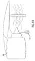
- FIG. 1Aillustrates a cutaway view of an exemplary turbine, in accordance with the present invention.
- FIG. 1Billustrates a side view of the exemplary turbine, in accordance with the present invention.
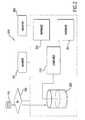
- FIG. 2illustrates a wash optimization system, in accordance with embodiments of the present invention.
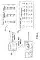
- FIG. 3illustrates exemplary identified contaminate data used for selecting an optimized wash procedure, in accordance with embodiments of the present invention.
- FIG. 4illustrates an exemplary screen shot of compared performance data, in accordance with embodiments of the present invention.
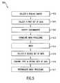
- FIG. 5illustrating wash optimization method 500 , in accordance with the present invention.
- the present inventionrelates to sampling and identify fouling to determine its composition, selecting a washing product comprising one or more detergents and/or wetting agents based on the fouling composition, cleaning a gas turbine compressor using the selected cleaner, and monitoring ambient conditions, turbine performance, and/or other factors to assess the effectiveness of the selected cleaner. Based on this assessment, the selected washing product may be re-selected and/or adjusted as appropriate.
- FIG. 1Aa cross-sectional view of an exemplary turbine 100 is shown. Arrows depict the direction of the air flow. Ambient air enters the duct 101 via the weather louver 102 , via the trash screen 103 , and via the air filter 104 to the inlet of the gas turbine 100 . Washing a gas turbine 100 may be performed by injecting a wash solution 121 from a nozzle 111 , upstream of the compressor 141 , which is then forced through the compressor 141 , thereby washing off and removing residual build up of fouling from the compressor 141 .
- This solution 121may include, for example, water, various chemical agents, detergents, solvents, or any combination thereof.
- a mixture 151comprising the washing solution 121 and fouling removed during the wash is formed.
- Some of this mixture 151is forced out of a rear portion (not shown) of the gas turbine 100 , while the rest of the mixture 151 collects in a discharge drain 131 .
- a sample of the discharged mixture 151i.e., a ‘water wash and rinse sample’, may be utilized to determine the composition of the fouling comprised therein.
- FIG. 1Ba side view of an exemplary turbine 100 is shown having a sample of the discharged mixture 151 being collected therefrom.
- a sample of foulingmay be obtained directly from a blade of the turbine.
- a sampleis known as a ‘physical sample’.
- Physical samplesmay be removed from turbine blades using any appropriate means, such as for example, using a solvent, fine abrasive paper, etc. It will be recognized by those skilled in the art, that a sample of fouling may be obtained manually, mechanically, robotically, or by any other appropriate means.
- the wash optimization system 200includes a computer 210 .
- the computer 210may include a storage means (not shown).
- the storage meansmay include a random access memory (RAM) and/or a non-volatile memory such as read-only memory (ROM).
- RAMrandom access memory
- ROMread-only memory
- a storage meanscan include various types of physical devices for temporary and/or persistent storage of data including, but not limited to, solid state, magnetic, optical and combination devices.
- the storage meansmay be implemented using one or more physical devices such as DRAM, PROMS, EPROMS, EEPROMS, flash memory, and the like.
- the storage meansmay further comprise a computer program product including software code portions for performing optimization steps in accordance with embodiments of the present invention when the computer program product is run on the computer, as further discussed below.
- the computer 210may be connected to a plurality of external devices such as, for example, databases such as 251 and 252 , monitoring units 261 and 262 , networks, I/O, external memories, sensors, measuring devices, and other appropriate peripheral devices.
- the wash optimization system 200further includes an identification unit 230 , which may be used to isolate the one or more contaminates from a collection means (not shown), of sample 151 and/or analyze and identify the one or more contaminates.
- the collection meansmay be, for example, solution, detergent, solvent, chemical agent, abrasive paper, and the like.
- the identification unit 230is be used to separate the one or more contaminates from the sample 151 provided by the collection means, thereby producing a sample of one or more contaminates, hereinafter a ‘contaminate sample’ 220 .
- the identification unit 230is preferably a mass spectrometer.
- mass spectrometersare commonly used to measure the electron shell spectrum of chemical elements that make up a solution and allow identification of compounds that make up the solution.
- the identification unit 230or in a preferred embodiment, mass spectrometer, is then used to identify the one or more contaminates of sample 220 . As a result, data regarding the identified contaminates is produced. The identified data intends to accomplish two tasks.
- the total dissolved particles read outwill provide an indication of compressor cleanliness; the lower total dissolved solids indicates, the higher degree of cleaning.
- the composition of the resulting rinse and fouling removedindicates what the contaminate is.
- the data producedmay be displayed by identification unit 230 , printed, etc. or, preferably, the computer 210 is connected to the identification unit 230 and the resulting identified contaminate data is displayed by the computer 210 . Referring briefly to FIG. 3 , exemplary identified data 311 is shown.
- the wash optimization system 200may also include a washing product database 251 .
- This database 251may comprise a manually searchable document or a computer readable product. If the database 251 , is a computer readable product, the washing product database 251 is preferably connected to the computer 210 , but is not limited thereto.
- the term ‘washing products’, as described herein,may be, but is not limited to, any appropriate detergent, chemical agent, solvent, wetting agent, or any other appropriate washing products, or any combination thereof.
- the washing product database 251preferably includes a plurality of commercially available washing products and information relating to the solubility of known contaminates in each of the plurality of washing products.
- washing productsare preferably categorized according to their respective ability to remove various contaminates. More specifically, each washing product within the washing product database 251 , preferably comprises a listing of contaminates that the respective product can remove and an established scale rating of how effective the product is in removing the contaminate.
- the database 251may be searched by any appropriate means.
- the computer 210is preferably programmed to compare the one or more identified contaminates to washing products of database 251 .
- the computer 210may be used to perform a manual or automated search of washing products in database 251 wherein one or more contaminates are compared to the solubility of the one or more washing products.
- washing products of database 251are searched using a search engine feature and as a result, a list of commercially available washing products may be produced. The resulting list is categorized according to the ability of the washing product to remove various contaminates.
- each washing product within the populated listcomprises a listing of contaminates that the respective washing products can remove, and an established scale rating of how well the products can remove particular contaminates.
- the database 251comprises data regarding an optimal amount of time with which to apply the washing product to each contaminate. More specifically, for each washing product, listed is the amount of time required for that washing product to remove an amount of a given contaminate. As discussed further, these times are preferably utilized in predetermining the amount of time to apply the one or more selected washing products.
- the computer 210is then programmed to and used to plot the listed washing products on a solubility index, in order to determine the best washing product to use for removing a specific contaminate or combination of contaminates.
- solubility indexis a measure of how soluble a chemical compound is in a solution, which is expressed as a time to achieve so much of the material into solution. Referring briefly to FIG. 3 , an exemplary solubility index 312 is shown.
- the wash optimization system 200may also include an ambient condition database 252 .
- the ambient condition database 252is a computer readable product connected to the computer 210 , although the ambient condition database 252 may comprise any manually searchable document, but is not limited thereto.
- foulingdoes not have a defined composition and typically any number of factors may influence its composition. For example, types of contaminates and quantities of contaminates may vary from location to location, as one location may have a higher concentration of a certain contaminate, whereas a different location may have a lower concentration of that contaminate or no trace of the contaminate at all.
- ambient condition database 252preferably includes data relating to such ambient conditions.
- the ambient conditionsmay include, but are not limited to, weather temperature, weather humidity, weather pressure, season, and location.
- ambient conditionsare preferably categorized according to their respective contaminate composition. More specifically, each ambient condition comprises a listing of contaminates associated with the condition. For example, and solely for illustrative purposes, if the ambient condition was the season of Spring, then one of the listed conditions might be pollen.
- the wash optimization system 200may also include an ambient condition monitoring unit 261 which may monitor ambient conditions to allow the turbine performance to be corrected to a common ambient reference point. This will allow performance data to be used as the second check of cleaning effectiveness in order to more effectively help identify other factors with the equipment that may be hindering turbine performance.
- the ambient condition monitoring unit 261may be connected to computer 210 or may be connected to the ambient condition database 252 or preferably both. Additionally, information relating to conditions collected by the ambient condition monitoring unit 261 may be transmitted directly to the computer 210 or to the ambient condition database 252 or preferably both.
- the ambient condition monitoring unit 261is a weather monitoring unit that collects ambient weather conditions.
- the ambient conditionsmay comprise environmental factors that possibly influence the operation of the gas turbine, including but limited to, weather temperature, weather humidity, and weather air pressure.
- the computer 210may further be programmed to formulate a wash procedure.
- the computer 210preferably formulates the wash procedure by selecting the best washing products according to the results obtained from the identification unit 230 as cross-referenced with the washing product database 251 , the ambient condition database 252 , and by monitoring ambient conditions, as well as by calculating the optimal time for application of the selected washing product.
- the optimal timemay be calculated according data contained in washing product database 251 .
- washing procedureused throughout describes the selected washing products and the application of those products for a predetermined amount of time.
- the collected dataincludes ambient data, as previously discussed, as well as turbine performance data.
- the computer 210may be further programmed to collect data relating to ambient conditions and/or turbine performance.
- the wash optimization system 200may include a turbine monitoring unit 262 .
- the turbine monitoring unit 262may include, but is not limited to, sensors, gauges, measuring devices, and other appropriate devices, and may monitor, for example, such things as fuel flow, thrust, output, and turbine pressure. Data may be collected from the turbine monitoring unit 262 manually or automatically and preferably is transferred to computer 210 . Preferably, the computer 210 is used to display a plurality of information regarding the performance data collected.
- the effectiveness of a particular washing procedure usedmay be determined by comparing the performance of the turbine before and after being washed.
- the washing procedure selectedacts to improve and preferably maximize performance of a turbine by removing all, but trace amounts of contaminates, therefrom.
- an ideal performance benchmarkis preferably determined such that the benchmark represents an expected level of performance of the turbine. Therefore, in a preferred embodiment, the computer 210 is further programmed to (a) compare first and second data sets collected before the turbine is washed with first and second data sets collected after the turbine is washed; and (b) formulate an optimized wash procedure.
- the computer 210is used to display a plurality of information regarding the compared performance data collected. Referring briefly to FIG. 4 , an exemplary screen shot of the compared performance data 400 is shown.
- the computer 210is programmed to compare the turbine performance data collected after the wash procedure to the performance data collected before the wash, to determine the increase, or lack thereof, in turbine performance.
- the increasemay be compared using the computer 210 to a benchmark performance level.
- the increaseis compared by computer 210 to the benchmark performance level, to determine if the selected washing procedure resulted in an optimal wash, thereby resulting in a restoration of maximum turbine performance.
- the computer 210is preferably configured to reformulate the selected washing procedure, in ways already discussed, so as to optimally wash the turbine, thus providing maximum performance to the turbine.
- wash optimization system 200may be used in conjunction with any conventional washing system, in accordance with the present invention.
- U.S. Pat. No. 5,868,860issued Feb. 9, 1999, and in PCT/SE Patent Application 2004/000194, filed Feb. 16, 2004 discloses examples of the washing of gas turbine compressors are herein incorporated by reference.
- wash optimization system 200is connected to a turbine washing unit or system, such as the system described in the aforementioned patents, and furthermore directly connected to the computer 210 such that the computer 210 may control the washing unit.
- the formulated and reformulated washing proceduresmay be controlled by the computer 210 and implemented in a washing system.
- the wash optimization system 200may be used repeatedly, as many times as desired. Preferably, the wash optimization system 200 is used two or more times and the ambient and performance data collected before and after each wash may tracked and saved. Using the tracked data, a performance trend may be developed. The computer 210 may be further programmed to track, save, develop, and display such a performance trend, based on the sets of collected data. Referring to FIG. 4 , graph 410 illustrates an exemplary performance trend plot, in accordance with the present invention.
- wash optimization method 500begins at step 510 , wherein a fouling sample is collected.
- a fouling sampleis collected.
- a large amount of airborne contaminatesare fed into the compressor and as a result, fouling adheres to and collects in the compressor of the turbine. Therefore, in order to maintain optimum performance of the turbine, the fouling should be removed.
- the removal of such foulingmay be done by washing. Washing a gas turbine may be performed by injecting a wash solution upstream of a compressor inlet, which is then forced through the compressor.
- the solutionmay include water, various chemical agents, detergents, solvents, or any combination thereof, but is not limited thereto.
- Conventional turbinestypically include a discharge drain or an equivalent discharge apparatus, wherein deposits of discharge from the compressor collect. While washing a turbine system, the solution, forced through the compressor, washes off and removes the residual build up of fouling. Thus, a mixture comprising the washing solution used in the washing procedure and the fouling removed during the wash is formed. Some of this mixture is forced out of the rear of the gas turbine, while the rest of the mixture collects in the discharge drain.
- a sample of the discharged mixtureis taken from the discharge drain after a turbine is washed. This is referred to as ‘a water wash and rinse sample’.
- the water wash and rinse samplepreferably comprises one or more contaminates and the original washing solution.
- the sample of foulingmay include a physical sample taken directly from a blade of the turbine. This may be done using any appropriate means such as, for example, using a solvent, a fine abrasive paper, or any other appropriate means, as will be understood by one of ordinary skill in the art.
- the contaminatesare isolated from the solution using a spectral analysis system, namely a mass spectrometer.
- mass spectrometersare commonly used measure the electron shell spectrum of chemical elements that make up the solution and allow identification of the compounds that make up the solution are devices, and therefore are preferably used in embodiments of the present invention.
- the mass spectrometeris preferably used to filter out contaminates from the washing solution comprising, for example, solvents, chemical agents, detergents, and the like. As a result, an isolated sample of the one or more contaminates is produced.
- any appropriate means of isolating the contaminatesmay be utilized. For example, scraping off the contaminates, thus isolating the contaminates from the abrasive paper. It should be understood however, that, in accordance with the present invention, any appropriate means of isolating the one or more contaminates may be utilized.
- a first set of datais collected.
- foulingdoes not have a defined composition and typically any number of factors may influence its composition.
- types of contaminates and quantities of contaminatesmay vary from location to location; one location may have a higher concentration of a certain contaminate, whereas a different location may have a lower concentration of that contaminate or even no trace of that contaminate.
- contaminationmay have a seasonal variation due to such things as local vegetation, industrial process, prevailing weather, etc. Other ambient factors may also vary.
- the first set of collected datamay be data relating to ambient conditions.
- the ambient conditionsmay comprise environmental factors that may influence the operation of the gas turbine, including but limited to, weather temperature, weather humidity and weather air pressure.
- the collection of ambient conditionsis used as a secondary measure of turbine cleaning effectiveness and aids in defining the optimal timing for performing a turbine wash.
- the first set of collected datamay be data relating to turbine performance parameters.
- evaluating the performance of a turbine before and after washingacts to provide a better gauge of the effectiveness of the selected washing procedure. Therefore, in another embodiment, a turbine monitoring unit collects turbine performance parameters.
- the turbine performance parametersmay comprise, for example, fuel flow, thrust, output, and turbine pressure.
- the first set of collected datacomprises both ambient conditions and turbine parameters.
- step 512the sample of one or more contaminates is analyzed, to identify the contaminates comprising the fouling. Any conventional means for identifying contaminates may be utilized.
- the mass spectrometersuch as the one previously discussed, is used to identify the one or more contaminates.
- wash procedurerefers to the selecting of one or more washing products and determining the amount of time to apply the products to the turbine.
- the washing product or combination of washing productsmay be selected. However, selecting an appropriate solution involves evaluating various criteria.
- solubility of the contaminationwill be greater for specific washing products; hence having identified the specific type of contaminates, it is desirable to select the most effective washing product(s) to best remove the contaminates.
- one of the criteria involved in selecting a washing productmay be to evaluate the product's ability to remove the identified contaminates.
- the selection of appropriate washing productsmay be done using a computer, such as the computer 210 previously described or may be done manually by referencing data relating to contaminate solubility in various washing products.
- a computeris used, wherein the computer is connected to a database comprising washing products, including those that are commercially available.
- the databasemay further includes information relating to the solubility of known contaminates.
- washing productsare preferably categorized according to their respective ability to remove various contaminates. Additionally, each washing product comprises an optimal amount of time with which to apply the washing product to each contaminate. More specifically, for each washing product, listed is the amount of time required for that washing product to remove an amount of a given contaminate. As discussed further, these times are preferably utilized in predetermining the amount of time to apply the one or more selected washing products.
- the computermay be used to perform a manual or automated search of the database.
- the databaseis searched using a search engine feature and which generates a list of commercially available washing products. The listed products are then plotted against a solubility index, in order to determine the best product or products to use for removing a specific contaminates. Together with the ambient factor data collected, one or more washing products may then be selected to remove the contaminates from the turbine according to the solubility index.
- step 514the turbine from which the sample of fouling was taken, is then washed using the selected one or more washing products for a predetermined amount of time. Any conventional washing system and method may be utilized, in accordance with the present invention.
- a second set of datais collected.
- the second set of collected datacomprises information relating to both ambient conditions and turbine performance parameters.
- the ambient conditionsmay comprise environmental factors that may influence the operation of the gas turbine, such as temperature, humidity and air pressure.
- a turbine monitoring unitcollects turbine performance parameters.
- the turbine performance parametersmay comprise, for example, fuel flow, thrust, turbine output, and turbine pressure.
- the first and second sets of dataare compared.
- optimal performance of a turbinemaximizes production, while minimizing the amount of fuel used. Contaminates act to reduce the compressor efficiency, and therefore the collection of contaminates is preferably collected in a manner other than by washing the turbine.
- datais preferably collected both before and after washing.
- the effectivenessmay be determined by comparing the performance of the turbine before and after the wash.
- the washing products and application time selectedresult in improved and preferably maximized performance of the turbine.
- an ideal performance benchmarkis determined such that the benchmark represents an expected level of performance of the turbine.
- the turbine performance data collected after the washis compared to the performance data collected before the wash, to determine the increase, or lack thereof, in turbine performance.
- performancemay and, preferably will, increase substantially. Therefore, it is also preferred that the increase also be compared to the benchmark performance level, to determine if the selected washing products and application time resulted in an optimal wash.
- Step 517it is preferable to reformulate the selected washing procedure so as to optimally wash the turbine, thus providing maximum turbine performance. Therefore, the ambient conditions are again evaluated after the wash and are further compared to the conditions before the wash. In addition to the compared performance data and ambient condition data, the contaminate solubility is again evaluated and a subsequent washing procedure, of washing products and application time, is formulated accordingly.
Landscapes
- Engineering & Computer Science (AREA)
- Mechanical Engineering (AREA)
- General Engineering & Computer Science (AREA)
- Cleaning By Liquid Or Steam (AREA)
- Structures Of Non-Positive Displacement Pumps (AREA)
- Sampling And Sample Adjustment (AREA)
Abstract
Description
Claims (23)
Priority Applications (2)
| Application Number | Priority Date | Filing Date | Title |
|---|---|---|---|
| US11/866,530US8685176B2 (en) | 2006-10-16 | 2007-10-03 | System and method for optimized gas turbine compressor cleaning and performance measurement |
| US12/687,594US8273184B2 (en) | 2006-10-16 | 2010-01-14 | System and method for optimized gas turbine compressor cleaning and performance measurement |
Applications Claiming Priority (2)
| Application Number | Priority Date | Filing Date | Title |
|---|---|---|---|
| US85204106P | 2006-10-16 | 2006-10-16 | |
| US11/866,530US8685176B2 (en) | 2006-10-16 | 2007-10-03 | System and method for optimized gas turbine compressor cleaning and performance measurement |
Related Child Applications (1)
| Application Number | Title | Priority Date | Filing Date |
|---|---|---|---|
| US12/687,594DivisionUS8273184B2 (en) | 2006-10-16 | 2010-01-14 | System and method for optimized gas turbine compressor cleaning and performance measurement |
Publications (2)
| Publication Number | Publication Date |
|---|---|
| US20080173330A1 US20080173330A1 (en) | 2008-07-24 |
| US8685176B2true US8685176B2 (en) | 2014-04-01 |
Family
ID=38955196
Family Applications (2)
| Application Number | Title | Priority Date | Filing Date |
|---|---|---|---|
| US11/866,530Active2030-11-21US8685176B2 (en) | 2006-10-16 | 2007-10-03 | System and method for optimized gas turbine compressor cleaning and performance measurement |
| US12/687,594Expired - Fee RelatedUS8273184B2 (en) | 2006-10-16 | 2010-01-14 | System and method for optimized gas turbine compressor cleaning and performance measurement |
Family Applications After (1)
| Application Number | Title | Priority Date | Filing Date |
|---|---|---|---|
| US12/687,594Expired - Fee RelatedUS8273184B2 (en) | 2006-10-16 | 2010-01-14 | System and method for optimized gas turbine compressor cleaning and performance measurement |
Country Status (3)
| Country | Link |
|---|---|
| US (2) | US8685176B2 (en) |
| EP (1) | EP1914010B1 (en) |
| SG (2) | SG175631A1 (en) |
Cited By (5)
| Publication number | Priority date | Publication date | Assignee | Title |
|---|---|---|---|---|
| US20140174163A1 (en)* | 2012-12-20 | 2014-06-26 | General Electric Company | Systems and Methods For Measuring Fouling in a Turbine System |
| US9932895B2 (en) | 2013-10-10 | 2018-04-03 | Ecoservices, Llc | Radial passage engine wash manifold |
| US10364699B2 (en) | 2013-10-02 | 2019-07-30 | Aerocore Technologies Llc | Cleaning method for jet engine |
| US10807738B2 (en) | 2016-12-01 | 2020-10-20 | General Electric Company | Maintenance operation analytics |
| US11643946B2 (en) | 2013-10-02 | 2023-05-09 | Aerocore Technologies Llc | Cleaning method for jet engine |
Families Citing this family (37)
| Publication number | Priority date | Publication date | Assignee | Title |
|---|---|---|---|---|
| US8524010B2 (en)* | 2007-03-07 | 2013-09-03 | Ecoservices, Llc | Transportable integrated wash unit |
| US8277647B2 (en) | 2007-12-19 | 2012-10-02 | United Technologies Corporation | Effluent collection unit for engine washing |
| DE102008019892A1 (en)* | 2008-04-21 | 2009-10-29 | Mtu Aero Engines Gmbh | Method for cleaning an aircraft engine |
| US20100102835A1 (en)* | 2008-10-27 | 2010-04-29 | General Electric Company | Method and system for detecting a corrosive deposit in a compressor |
| US20100242994A1 (en)* | 2009-03-30 | 2010-09-30 | Gas Turbine Efficiency Sweden Ab | Device and method for collecting waste water from turbine engine washing |
| DE102009033944A1 (en)* | 2009-07-14 | 2011-01-20 | Alfred Kärcher Gmbh & Co. Kg | Cleaning device and method for controlling access to a cleaning device |
| US20110106680A1 (en)* | 2009-10-30 | 2011-05-05 | General Electric Company | Turbine operation degradation determination system and method |
| US8751423B2 (en) | 2010-11-30 | 2014-06-10 | General Electric Company | Turbine performance diagnostic system and methods |
| US10272475B2 (en)* | 2012-11-07 | 2019-04-30 | General, Electric Company | Offline compressor wash systems and methods |
| FR3005108B1 (en)* | 2013-04-30 | 2018-01-05 | Safran Helicopter Engines | TURBOMACHINE AIR INTAKE CASTER WASHING DEVICE |
| US9951646B2 (en)* | 2013-07-01 | 2018-04-24 | General Electric Company | Gas turbine on-line water wash system and method |
| EP2853970B1 (en) | 2013-09-30 | 2019-03-13 | MTU Aero Engines GmbH | Method for carrying out maintenance on an engine |
| US20150121888A1 (en)* | 2013-11-05 | 2015-05-07 | General Electric Company | Gas turbine online wash control |
| US9874108B2 (en)* | 2014-07-08 | 2018-01-23 | Rolls-Royce Corporation | Cleaning system for a turbofan gas turbine engine |
| US20160076457A1 (en)* | 2014-09-12 | 2016-03-17 | General Electric Company | System and method for providing a film treatment to a surface |
| CN109661505B (en) | 2016-06-29 | 2021-10-22 | 通用电气公司 | Method for wastewater-based condition assessment |
| US11143056B2 (en)* | 2016-08-17 | 2021-10-12 | General Electric Company | System and method for gas turbine compressor cleaning |
| US10227891B2 (en)* | 2017-03-29 | 2019-03-12 | General Electric Company | Gas turbine engine wash system |
| US20180313225A1 (en) | 2017-04-26 | 2018-11-01 | General Electric Company | Methods of cleaning a component within a turbine engine |
| SG10201707125YA (en)* | 2017-08-31 | 2019-03-28 | United Technologies Corp | Directional water jet cleaning of engine blades |
| US11268449B2 (en)* | 2017-09-22 | 2022-03-08 | General Electric Company | Contamination accumulation modeling |
| US11371385B2 (en) | 2018-04-19 | 2022-06-28 | General Electric Company | Machine foam cleaning system with integrated sensing |
| US11707819B2 (en) | 2018-10-15 | 2023-07-25 | General Electric Company | Selectively flexible extension tool |
| US12194620B2 (en) | 2018-10-15 | 2025-01-14 | Oliver Crisipin Robotics Limited | Selectively flexible extension tool |
| US10809673B2 (en)* | 2018-11-07 | 2020-10-20 | International Business Machines Corporation | Wash related to contaminant exposure time |
| US11702955B2 (en) | 2019-01-14 | 2023-07-18 | General Electric Company | Component repair system and method |
| US12405187B2 (en) | 2019-10-04 | 2025-09-02 | General Electric Company | Insertion apparatus for use with rotary machines |
| US11692650B2 (en) | 2020-01-23 | 2023-07-04 | General Electric Company | Selectively flexible extension tool |
| US11752622B2 (en) | 2020-01-23 | 2023-09-12 | General Electric Company | Extension tool having a plurality of links |
| US11613003B2 (en) | 2020-01-24 | 2023-03-28 | General Electric Company | Line assembly for an extension tool having a plurality of links |
| US11371437B2 (en) | 2020-03-10 | 2022-06-28 | Oliver Crispin Robotics Limited | Insertion tool |
| US12091981B2 (en) | 2020-06-11 | 2024-09-17 | General Electric Company | Insertion tool and method |
| US12416800B2 (en) | 2021-01-08 | 2025-09-16 | General Electric Company | Insertion tool |
| US11654547B2 (en) | 2021-03-31 | 2023-05-23 | General Electric Company | Extension tool |
| CN113988480B (en)* | 2021-12-21 | 2022-03-15 | 北京太阳宫燃气热电有限公司 | Gas equipment filter life prediction method and computer readable storage medium |
| JP7717000B2 (en)* | 2022-02-01 | 2025-08-01 | 三菱重工コンプレッサ株式会社 | Compressor System |
| US20240175398A1 (en)* | 2022-11-29 | 2024-05-30 | Pratt & Whitney Canada Corp. | Method and system for mitigating corrosion and/or erosion in an aircraft engine |
Citations (31)
| Publication number | Priority date | Publication date | Assignee | Title |
|---|---|---|---|---|
| DE2154594A1 (en)* | 1971-11-03 | 1973-05-17 | Fraunhofer Ges Forschung | Aerosol ejection evaluation - using activated particles in respiratory simulator |
| DE2701823A1 (en) | 1976-01-29 | 1977-08-04 | Laszlo Arato | Programmed washing unit for aircraft - .HAS SPRAY NOZZLES MOUNTED ON VEHICLE WITH POSITIONS CONTROLLED DEPENDENT ON LASER SENSORS |
| SU1076642A1 (en)* | 1982-08-13 | 1984-02-29 | Предприятие П/Я Р-6603 | Method of quality control of compressor passage section cleaning |
| US5011540A (en) | 1986-12-24 | 1991-04-30 | Mcdermott Peter | Method and apparatus for cleaning a gas turbine engine |
| US5241845A (en)* | 1991-02-28 | 1993-09-07 | Kabushiki Kaisha Toshiba | Neurocontrol for washing machines |
| US5318254A (en) | 1991-06-28 | 1994-06-07 | Conceptual Solutions, Inc. | Aircraft maintenance robot |
| EP0628477A1 (en) | 1993-06-11 | 1994-12-14 | Spar Aerospace Limited | Robot arm and method of its use |
| DE9420362U1 (en) | 1994-12-20 | 1995-03-30 | Hanrath, Rita, 52525 Heinsberg | Detergent catcher for compressor cleaning of aircraft engines |
| JPH07174714A (en)* | 1993-12-20 | 1995-07-14 | Mitsubishi Heavy Ind Ltd | Apparatus for detecting defect of cloth piece |
| US5438507A (en)* | 1993-06-19 | 1995-08-01 | Goldstar Co., Ltd. | Method of and apparatus for controlling washing operation of washer |
| KR19980017193A (en) | 1996-08-30 | 1998-06-05 | 이영리 | The antibacterial water purifier and the metal ion water produced in this water purifier |
| US5868860A (en) | 1995-06-07 | 1999-02-09 | Gas Turbine Efficiency Ab | Method of washing objects, such as turbine compressors |
| US5899217A (en) | 1998-02-10 | 1999-05-04 | Testman, Jr.; Frank L. | Engine wash recovery system |
| JP2000274206A (en)* | 1999-03-24 | 2000-10-03 | Hitachi Ltd | gas turbine |
| US20020001255A1 (en) | 2000-04-05 | 2002-01-03 | Flood Jeffrey D. | Portable concrete plant |
| WO2002036713A2 (en) | 2000-10-31 | 2002-05-10 | Pecherskikh, Pavel Borisovich | Mechanical and thermochemical method for removing hydrocarbon pollutants from objects |
| US20020096197A1 (en)* | 2001-01-19 | 2002-07-25 | Ackerman John Frederick | Methods and apparatus for washing gas turbine engines |
| US6491048B1 (en)* | 2000-05-26 | 2002-12-10 | Hydrochem Industrial Services, Inc. | Manifold for use in cleaning combustion turbines |
| US6675437B1 (en) | 1999-12-15 | 2004-01-13 | Shawn L. York | Portable high-temperature, high-pressure washing plant |
| US6694804B1 (en)* | 2002-09-23 | 2004-02-24 | Ppg Industries Ohio, Inc. | Method and device for evaluating and/or adjusting the cleaning performance of a cleaning liquid |
| FR2846221A1 (en)* | 2002-10-28 | 2004-04-30 | Oreal | Instrument to take samples from the surface of skin or integuments in vivo, for analysis, has a rotating abrasive disk pressed against the surface to collect dry sample material |
| US20040220817A1 (en)* | 2003-04-29 | 2004-11-04 | Katherine Sanville | Monitoring and controlling processes at a vehicle wash facility |
| US20050096832A1 (en) | 2003-10-29 | 2005-05-05 | Hitachi, Ltd. | Apparatus and method for determining date of gas turbine washing |
| DE10355353A1 (en)* | 2003-11-25 | 2005-07-21 | Alstom Technology Ltd | Method for cooling a gas stream supplied to a turbomachine, e.g. a gas turbine being used for electricity generation, includes controlling purity of cooling liquid by discharge of polluted fluid and supply of fresh fluid |
| WO2005077554A1 (en) | 2004-02-16 | 2005-08-25 | Gas Turbine Efficiency Ab | Method and apparatus for cleaning a turbofan gas turbine engine |
| JP2006061217A (en)* | 2004-08-24 | 2006-03-09 | Sharp Corp | dishwasher |
| US20060081521A1 (en)* | 2004-06-14 | 2006-04-20 | Carl-Johan Hjerpe | System and devices for collecting and treating waste water from engine washing |
| US7045021B2 (en)* | 2003-02-14 | 2006-05-16 | Unitec, Inc. | Customizable vehicle wash blending system and method |
| US7109095B2 (en)* | 2002-04-01 | 2006-09-19 | Matsushita Electric Industrial Co., Ltd. | Method for fabricating semiconductor device |
| US7114209B2 (en)* | 2001-12-12 | 2006-10-03 | The Procter & Gamble Company | Method for cleaning a soiled article |
| US20090050183A1 (en) | 2007-08-22 | 2009-02-26 | Rice Robert M | Integrated wash unit for a turbine engine |
Family Cites Families (8)
| Publication number | Priority date | Publication date | Assignee | Title |
|---|---|---|---|---|
| US2807961A (en)* | 1954-04-05 | 1957-10-01 | Standard Oil Co | Automatic liquid sampler |
| JPS5937026B2 (en)* | 1978-12-05 | 1984-09-07 | 東洋インキ製造株式会社 | Resin composition for aqueous coating |
| US4467640A (en)* | 1982-05-26 | 1984-08-28 | Chandler Evans, Inc. | Gas turbine engine power availability measurement |
| US6966994B2 (en)* | 2001-04-17 | 2005-11-22 | Caterpillar Inc | Contamination control for engines |
| US20030209256A1 (en)* | 2002-05-13 | 2003-11-13 | Shahin Tadayon | Jet wet suit cover system for gaspath cleaning |
| RU2249119C2 (en)* | 2003-04-09 | 2005-03-27 | Открытое акционерное общество "Техприбор" | Aircraft engine monitoring method |
| EP1574674A1 (en)* | 2004-03-03 | 2005-09-14 | Siemens Aktiengesellschaft | Method and device for detecting contaminants on turbine components |
| US9790808B2 (en)* | 2005-04-04 | 2017-10-17 | Ecoservices, Llc | Mobile on-wing engine washing and water reclamation system |
- 2007
- 2007-10-03USUS11/866,530patent/US8685176B2/enactiveActive
- 2007-10-08EPEP07019671.2Apatent/EP1914010B1/ennot_activeRevoked
- 2007-10-11SGSG2011075231Apatent/SG175631A1/enunknown
- 2007-10-11SGSG200716805-7Apatent/SG142238A1/enunknown
- 2010
- 2010-01-14USUS12/687,594patent/US8273184B2/ennot_activeExpired - Fee Related
Patent Citations (31)
| Publication number | Priority date | Publication date | Assignee | Title |
|---|---|---|---|---|
| DE2154594A1 (en)* | 1971-11-03 | 1973-05-17 | Fraunhofer Ges Forschung | Aerosol ejection evaluation - using activated particles in respiratory simulator |
| DE2701823A1 (en) | 1976-01-29 | 1977-08-04 | Laszlo Arato | Programmed washing unit for aircraft - .HAS SPRAY NOZZLES MOUNTED ON VEHICLE WITH POSITIONS CONTROLLED DEPENDENT ON LASER SENSORS |
| SU1076642A1 (en)* | 1982-08-13 | 1984-02-29 | Предприятие П/Я Р-6603 | Method of quality control of compressor passage section cleaning |
| US5011540A (en) | 1986-12-24 | 1991-04-30 | Mcdermott Peter | Method and apparatus for cleaning a gas turbine engine |
| US5241845A (en)* | 1991-02-28 | 1993-09-07 | Kabushiki Kaisha Toshiba | Neurocontrol for washing machines |
| US5318254A (en) | 1991-06-28 | 1994-06-07 | Conceptual Solutions, Inc. | Aircraft maintenance robot |
| EP0628477A1 (en) | 1993-06-11 | 1994-12-14 | Spar Aerospace Limited | Robot arm and method of its use |
| US5438507A (en)* | 1993-06-19 | 1995-08-01 | Goldstar Co., Ltd. | Method of and apparatus for controlling washing operation of washer |
| JPH07174714A (en)* | 1993-12-20 | 1995-07-14 | Mitsubishi Heavy Ind Ltd | Apparatus for detecting defect of cloth piece |
| DE9420362U1 (en) | 1994-12-20 | 1995-03-30 | Hanrath, Rita, 52525 Heinsberg | Detergent catcher for compressor cleaning of aircraft engines |
| US5868860A (en) | 1995-06-07 | 1999-02-09 | Gas Turbine Efficiency Ab | Method of washing objects, such as turbine compressors |
| KR19980017193A (en) | 1996-08-30 | 1998-06-05 | 이영리 | The antibacterial water purifier and the metal ion water produced in this water purifier |
| US5899217A (en) | 1998-02-10 | 1999-05-04 | Testman, Jr.; Frank L. | Engine wash recovery system |
| JP2000274206A (en)* | 1999-03-24 | 2000-10-03 | Hitachi Ltd | gas turbine |
| US6675437B1 (en) | 1999-12-15 | 2004-01-13 | Shawn L. York | Portable high-temperature, high-pressure washing plant |
| US20020001255A1 (en) | 2000-04-05 | 2002-01-03 | Flood Jeffrey D. | Portable concrete plant |
| US6491048B1 (en)* | 2000-05-26 | 2002-12-10 | Hydrochem Industrial Services, Inc. | Manifold for use in cleaning combustion turbines |
| WO2002036713A2 (en) | 2000-10-31 | 2002-05-10 | Pecherskikh, Pavel Borisovich | Mechanical and thermochemical method for removing hydrocarbon pollutants from objects |
| US20020096197A1 (en)* | 2001-01-19 | 2002-07-25 | Ackerman John Frederick | Methods and apparatus for washing gas turbine engines |
| US7114209B2 (en)* | 2001-12-12 | 2006-10-03 | The Procter & Gamble Company | Method for cleaning a soiled article |
| US7109095B2 (en)* | 2002-04-01 | 2006-09-19 | Matsushita Electric Industrial Co., Ltd. | Method for fabricating semiconductor device |
| US6694804B1 (en)* | 2002-09-23 | 2004-02-24 | Ppg Industries Ohio, Inc. | Method and device for evaluating and/or adjusting the cleaning performance of a cleaning liquid |
| FR2846221A1 (en)* | 2002-10-28 | 2004-04-30 | Oreal | Instrument to take samples from the surface of skin or integuments in vivo, for analysis, has a rotating abrasive disk pressed against the surface to collect dry sample material |
| US7045021B2 (en)* | 2003-02-14 | 2006-05-16 | Unitec, Inc. | Customizable vehicle wash blending system and method |
| US20040220817A1 (en)* | 2003-04-29 | 2004-11-04 | Katherine Sanville | Monitoring and controlling processes at a vehicle wash facility |
| US20050096832A1 (en) | 2003-10-29 | 2005-05-05 | Hitachi, Ltd. | Apparatus and method for determining date of gas turbine washing |
| DE10355353A1 (en)* | 2003-11-25 | 2005-07-21 | Alstom Technology Ltd | Method for cooling a gas stream supplied to a turbomachine, e.g. a gas turbine being used for electricity generation, includes controlling purity of cooling liquid by discharge of polluted fluid and supply of fresh fluid |
| WO2005077554A1 (en) | 2004-02-16 | 2005-08-25 | Gas Turbine Efficiency Ab | Method and apparatus for cleaning a turbofan gas turbine engine |
| US20060081521A1 (en)* | 2004-06-14 | 2006-04-20 | Carl-Johan Hjerpe | System and devices for collecting and treating waste water from engine washing |
| JP2006061217A (en)* | 2004-08-24 | 2006-03-09 | Sharp Corp | dishwasher |
| US20090050183A1 (en) | 2007-08-22 | 2009-02-26 | Rice Robert M | Integrated wash unit for a turbine engine |
Non-Patent Citations (2)
| Title |
|---|
| European Patent Office 0 095 378 Nov. 1983.* |
| WIPO WO 96/40453 Dec. 1996.* |
Cited By (5)
| Publication number | Priority date | Publication date | Assignee | Title |
|---|---|---|---|---|
| US20140174163A1 (en)* | 2012-12-20 | 2014-06-26 | General Electric Company | Systems and Methods For Measuring Fouling in a Turbine System |
| US10364699B2 (en) | 2013-10-02 | 2019-07-30 | Aerocore Technologies Llc | Cleaning method for jet engine |
| US11643946B2 (en) | 2013-10-02 | 2023-05-09 | Aerocore Technologies Llc | Cleaning method for jet engine |
| US9932895B2 (en) | 2013-10-10 | 2018-04-03 | Ecoservices, Llc | Radial passage engine wash manifold |
| US10807738B2 (en) | 2016-12-01 | 2020-10-20 | General Electric Company | Maintenance operation analytics |
Also Published As
| Publication number | Publication date |
|---|---|
| SG175631A1 (en) | 2011-11-28 |
| US8273184B2 (en) | 2012-09-25 |
| EP1914010B1 (en) | 2016-08-17 |
| US20080173330A1 (en) | 2008-07-24 |
| EP1914010A2 (en) | 2008-04-23 |
| US20100116292A1 (en) | 2010-05-13 |
| SG142238A1 (en) | 2008-05-28 |
| EP1914010A3 (en) | 2010-09-15 |
Similar Documents
| Publication | Publication Date | Title |
|---|---|---|
| US8685176B2 (en) | System and method for optimized gas turbine compressor cleaning and performance measurement | |
| JP5354400B2 (en) | Automatic detection and control system and method for high pressure water cleaning application and collection applied to aircraft compressor cleaning | |
| Meher-Homji et al. | The fouling of axial flow compressors: Causes, effects, susceptibility, and sensitivity | |
| US8515719B2 (en) | Apparatus anomaly monitoring method and system | |
| Aretakis et al. | Compressor washing economic analysis and optimization for power generation | |
| EP2257933B1 (en) | Method for diagnosing a gas turbine | |
| JP5449975B2 (en) | Method and system for detecting corrosion deposits in a compressor | |
| CN1519765A (en) | Operational support systems for power plants | |
| CN104850904A (en) | Analysis method for optimizing gas turbine overhaul and maintenance scheme | |
| JP2003303014A (en) | Plant equipment maintenance management method and apparatus | |
| US20090271149A1 (en) | Analysis Method | |
| CN114215705A (en) | Wind turbine generator fault early warning method and system | |
| US20110257932A1 (en) | Method for detecting variance in semiconductor processes | |
| CN110928248B (en) | A method for determining the degree of deterioration of gas turbine performance | |
| CN116379043B (en) | A fault detection method and system for spin-on oil filters | |
| CN118861589B (en) | Intelligent bolt state detection method and device | |
| JP2002108440A (en) | Damage diagnosis device for power generation equipment | |
| Sánchez et al. | Determining compressor wash programmes for fouled gas turbines | |
| CN117905683B (en) | Intelligent control method for lithium battery air compressor | |
| CN115828718A (en) | Gas path performance diagnosis method of gas turbine | |
| Dominizi et al. | Comparative Life Cycle Assessment of Different Gas Turbine Axial Compressor Water Washing Systems | |
| WO2018004873A1 (en) | Methods for effluent based condition assessment | |
| Liu et al. | Data analytics for performance monitoring of gas turbine engine | |
| CN101934178A (en) | Method and system for managing a pollution-prevention facility | |
| CN116362582B (en) | Activated carbon accumulated adsorption efficiency evaluation method and system based on integration method |
Legal Events
| Date | Code | Title | Description |
|---|---|---|---|
| AS | Assignment | Owner name:GAS TURBINE EFFICIENCY SWEDEN AB, SWEDEN Free format text:ASSIGNMENT OF ASSIGNORS INTEREST;ASSIGNOR:WAGNER, THOMAS;REEL/FRAME:019932/0422 Effective date:20071005 | |
| AS | Assignment | Owner name:PRATT & WHITNEY LINE MAINTENANCE SERVICES, INC., C Free format text:ASSIGNMENT OF ASSIGNORS INTEREST;ASSIGNORS:GAS TURBINE EFFICIENCY AB;GAS TURBINE EFFICIENCY SWEDEN AS;REEL/FRAME:025859/0110 Effective date:20110111 | |
| AS | Assignment | Owner name:ECOSERVICES, LLC, CONNECTICUT Free format text:ASSIGNMENT OF ASSIGNORS INTEREST;ASSIGNOR:PRATT & WHITNEY LINE MAINTENANCE SERVICES, INC.;REEL/FRAME:030238/0298 Effective date:20130311 | |
| STCF | Information on status: patent grant | Free format text:PATENTED CASE | |
| AS | Assignment | Owner name:PRATT & WHITNEY LINE MAINTENANCE SERVICES, INC., C Free format text:CORRECTIVE ASSIGNMENT TO CORRECT THE THE NAME OF THE 2ND ASSIGNOR PREVIOUSLY RECORDED AT REEL: 025859 FRAME: 0110. ASSIGNOR(S) HEREBY CONFIRMS THE ASSIGNMENT;ASSIGNORS:GAS TURBINE EFFICIENCY AB;GAS TURBINE EFFICIENCY SWEDEN AB;REEL/FRAME:044167/0036 Effective date:20110118 | |
| FEPP | Fee payment procedure | Free format text:MAINTENANCE FEE REMINDER MAILED (ORIGINAL EVENT CODE: REM.) | |
| FEPP | Fee payment procedure | Free format text:ENTITY STATUS SET TO UNDISCOUNTED (ORIGINAL EVENT CODE: BIG.) | |
| FEPP | Fee payment procedure | Free format text:SURCHARGE FOR LATE PAYMENT, LARGE ENTITY (ORIGINAL EVENT CODE: M1554) | |
| MAFP | Maintenance fee payment | Free format text:PAYMENT OF MAINTENANCE FEE, 4TH YEAR, LARGE ENTITY (ORIGINAL EVENT CODE: M1551) Year of fee payment:4 | |
| MAFP | Maintenance fee payment | Free format text:PAYMENT OF MAINTENANCE FEE, 8TH YEAR, LARGE ENTITY (ORIGINAL EVENT CODE: M1552); ENTITY STATUS OF PATENT OWNER: LARGE ENTITY Year of fee payment:8 | |
| MAFP | Maintenance fee payment | Free format text:PAYMENT OF MAINTENANCE FEE, 12TH YEAR, LARGE ENTITY (ORIGINAL EVENT CODE: M1553); ENTITY STATUS OF PATENT OWNER: LARGE ENTITY Year of fee payment:12 |