US8685044B2 - Systems and methods for attaching a prosthesis with a body lumen or hollow organ - Google Patents
Systems and methods for attaching a prosthesis with a body lumen or hollow organDownload PDFInfo
- Publication number
- US8685044B2 US8685044B2US13/495,836US201213495836AUS8685044B2US 8685044 B2US8685044 B2US 8685044B2US 201213495836 AUS201213495836 AUS 201213495836AUS 8685044 B2US8685044 B2US 8685044B2
- Authority
- US
- United States
- Prior art keywords
- fastener
- carrier
- tool
- phase
- implantation
- Prior art date
- Legal status (The legal status is an assumption and is not a legal conclusion. Google has not performed a legal analysis and makes no representation as to the accuracy of the status listed.)
- Expired - Lifetime, expires
Links
- 238000000034methodMethods0.000titleclaimsabstractdescription16
- 210000000056organAnatomy0.000titleabstractdescription12
- 238000002513implantationMethods0.000claimsabstractdescription86
- 239000007943implantSubstances0.000claimsdescription15
- 238000012546transferMethods0.000claimsdescription6
- 230000008878couplingEffects0.000claimsdescription3
- 238000010168coupling processMethods0.000claimsdescription3
- 238000005859coupling reactionMethods0.000claimsdescription3
- 230000000717retained effectEffects0.000claimsdescription3
- 230000035515penetrationEffects0.000claims2
- 210000004204blood vesselAnatomy0.000abstractdescription7
- 230000007246mechanismEffects0.000description36
- 239000000463materialSubstances0.000description25
- 206010002329AneurysmDiseases0.000description8
- 210000002254renal arteryAnatomy0.000description7
- 230000004044responseEffects0.000description7
- 210000000709aortaAnatomy0.000description6
- 239000000969carrierSubstances0.000description5
- 239000004033plasticSubstances0.000description5
- 229920000728polyesterPolymers0.000description5
- 230000008439repair processEffects0.000description5
- 230000001143conditioned effectEffects0.000description4
- BASFCYQUMIYNBI-UHFFFAOYSA-NplatinumChemical compound[Pt]BASFCYQUMIYNBI-UHFFFAOYSA-N0.000description4
- 230000008569processEffects0.000description4
- 208000007474aortic aneurysmDiseases0.000description3
- 230000000712assemblyEffects0.000description3
- 238000000429assemblyMethods0.000description3
- 230000008901benefitEffects0.000description3
- KAATUXNTWXVJKI-UHFFFAOYSA-NcypermethrinChemical compoundCC1(C)C(C=C(Cl)Cl)C1C(=O)OC(C#N)C1=CC=CC(OC=2C=CC=CC=2)=C1KAATUXNTWXVJKI-UHFFFAOYSA-N0.000description3
- 201000010099diseaseDiseases0.000description3
- 208000037265diseases, disorders, signs and symptomsDiseases0.000description3
- 239000000835fiberSubstances0.000description3
- 238000011065in-situ storageMethods0.000description3
- 238000003754machiningMethods0.000description3
- 229910052751metalInorganic materials0.000description3
- 239000002184metalSubstances0.000description3
- 238000000465mouldingMethods0.000description3
- 230000003213activating effectEffects0.000description2
- 230000004913activationEffects0.000description2
- 229920000295expanded polytetrafluoroethylenePolymers0.000description2
- 230000006870functionEffects0.000description2
- 239000007769metal materialSubstances0.000description2
- 229910052697platinumInorganic materials0.000description2
- 238000000926separation methodMethods0.000description2
- 230000006641stabilisationEffects0.000description2
- 238000011105stabilizationMethods0.000description2
- 239000013589supplementSubstances0.000description2
- 208000002847Surgical WoundDiseases0.000description1
- 206010052428WoundDiseases0.000description1
- 208000027418Wounds and injuryDiseases0.000description1
- 208000002223abdominal aortic aneurysmDiseases0.000description1
- 230000003187abdominal effectEffects0.000description1
- 239000000853adhesiveSubstances0.000description1
- 238000004026adhesive bondingMethods0.000description1
- 230000001070adhesive effectEffects0.000description1
- 210000002376aorta thoracicAnatomy0.000description1
- 238000005452bendingMethods0.000description1
- 239000000560biocompatible materialSubstances0.000description1
- 230000015572biosynthetic processEffects0.000description1
- 230000000903blocking effectEffects0.000description1
- 230000017531blood circulationEffects0.000description1
- 210000001124body fluidAnatomy0.000description1
- 239000010839body fluidSubstances0.000description1
- 239000000919ceramicSubstances0.000description1
- 230000000295complement effectEffects0.000description1
- 230000003111delayed effectEffects0.000description1
- 239000004744fabricSubstances0.000description1
- 210000001105femoral arteryAnatomy0.000description1
- 230000008571general functionEffects0.000description1
- PCHJSUWPFVWCPO-UHFFFAOYSA-NgoldChemical compound[Au]PCHJSUWPFVWCPO-UHFFFAOYSA-N0.000description1
- 229910052737goldInorganic materials0.000description1
- 239000010931goldSubstances0.000description1
- 238000010438heat treatmentMethods0.000description1
- 210000003090iliac arteryAnatomy0.000description1
- 238000003780insertionMethods0.000description1
- 230000037431insertionEffects0.000description1
- 238000009434installationMethods0.000description1
- 229910052741iridiumInorganic materials0.000description1
- GKOZUEZYRPOHIO-UHFFFAOYSA-Niridium atomChemical compound[Ir]GKOZUEZYRPOHIO-UHFFFAOYSA-N0.000description1
- 230000000670limiting effectEffects0.000description1
- 230000014759maintenance of locationEffects0.000description1
- 238000004519manufacturing processMethods0.000description1
- 239000003550markerSubstances0.000description1
- 230000005012migrationEffects0.000description1
- 238000013508migrationMethods0.000description1
- 238000012986modificationMethods0.000description1
- 230000004048modificationEffects0.000description1
- HLXZNVUGXRDIFK-UHFFFAOYSA-Nnickel titaniumChemical compound[Ti].[Ti].[Ti].[Ti].[Ti].[Ti].[Ti].[Ti].[Ti].[Ti].[Ti].[Ni].[Ni].[Ni].[Ni].[Ni].[Ni].[Ni].[Ni].[Ni].[Ni].[Ni].[Ni].[Ni].[Ni]HLXZNVUGXRDIFK-UHFFFAOYSA-N0.000description1
- 229910001000nickel titaniumInorganic materials0.000description1
- 230000036961partial effectEffects0.000description1
- 230000000149penetrating effectEffects0.000description1
- 230000002829reductive effectEffects0.000description1
- 230000002787reinforcementEffects0.000description1
- 230000002441reversible effectEffects0.000description1
- 238000007789sealingMethods0.000description1
- 238000010008shearingMethods0.000description1
- 238000005476solderingMethods0.000description1
- 125000006850spacer groupChemical group0.000description1
- 238000001356surgical procedureMethods0.000description1
- 210000000115thoracic cavityAnatomy0.000description1
- 230000002792vascularEffects0.000description1
- 230000003313weakening effectEffects0.000description1
- 238000003466weldingMethods0.000description1
Images


Classifications
- A—HUMAN NECESSITIES
- A61—MEDICAL OR VETERINARY SCIENCE; HYGIENE
- A61B—DIAGNOSIS; SURGERY; IDENTIFICATION
- A61B17/00—Surgical instruments, devices or methods
- A61B17/10—Surgical instruments, devices or methods for applying or removing wound clamps, e.g. containing only one clamp or staple; Wound clamp magazines
- A—HUMAN NECESSITIES
- A61—MEDICAL OR VETERINARY SCIENCE; HYGIENE
- A61B—DIAGNOSIS; SURGERY; IDENTIFICATION
- A61B17/00—Surgical instruments, devices or methods
- A61B17/064—Surgical staples, i.e. penetrating the tissue
- A—HUMAN NECESSITIES
- A61—MEDICAL OR VETERINARY SCIENCE; HYGIENE
- A61B—DIAGNOSIS; SURGERY; IDENTIFICATION
- A61B17/00—Surgical instruments, devices or methods
- A61B17/068—Surgical staplers, e.g. containing multiple staples or clamps
- A—HUMAN NECESSITIES
- A61—MEDICAL OR VETERINARY SCIENCE; HYGIENE
- A61B—DIAGNOSIS; SURGERY; IDENTIFICATION
- A61B17/00—Surgical instruments, devices or methods
- A61B17/08—Wound clamps or clips, i.e. not or only partly penetrating the tissue ; Devices for bringing together the edges of a wound
- A—HUMAN NECESSITIES
- A61—MEDICAL OR VETERINARY SCIENCE; HYGIENE
- A61B—DIAGNOSIS; SURGERY; IDENTIFICATION
- A61B17/00—Surgical instruments, devices or methods
- A61B17/11—Surgical instruments, devices or methods for performing anastomosis; Buttons for anastomosis
- A61B17/115—Staplers for performing anastomosis, e.g. in a single operation
- A—HUMAN NECESSITIES
- A61—MEDICAL OR VETERINARY SCIENCE; HYGIENE
- A61F—FILTERS IMPLANTABLE INTO BLOOD VESSELS; PROSTHESES; DEVICES PROVIDING PATENCY TO, OR PREVENTING COLLAPSING OF, TUBULAR STRUCTURES OF THE BODY, e.g. STENTS; ORTHOPAEDIC, NURSING OR CONTRACEPTIVE DEVICES; FOMENTATION; TREATMENT OR PROTECTION OF EYES OR EARS; BANDAGES, DRESSINGS OR ABSORBENT PADS; FIRST-AID KITS
- A61F2/00—Filters implantable into blood vessels; Prostheses, i.e. artificial substitutes or replacements for parts of the body; Appliances for connecting them with the body; Devices providing patency to, or preventing collapsing of, tubular structures of the body, e.g. stents
- A61F2/02—Prostheses implantable into the body
- A61F2/04—Hollow or tubular parts of organs, e.g. bladders, tracheae, bronchi or bile ducts
- A61F2/06—Blood vessels
- A61F2/07—Stent-grafts
- A—HUMAN NECESSITIES
- A61—MEDICAL OR VETERINARY SCIENCE; HYGIENE
- A61B—DIAGNOSIS; SURGERY; IDENTIFICATION
- A61B17/00—Surgical instruments, devices or methods
- A61B17/08—Wound clamps or clips, i.e. not or only partly penetrating the tissue ; Devices for bringing together the edges of a wound
- A61B17/083—Clips, e.g. resilient
- A—HUMAN NECESSITIES
- A61—MEDICAL OR VETERINARY SCIENCE; HYGIENE
- A61B—DIAGNOSIS; SURGERY; IDENTIFICATION
- A61B17/00—Surgical instruments, devices or methods
- A61B17/064—Surgical staples, i.e. penetrating the tissue
- A61B2017/0649—Coils or spirals
- A—HUMAN NECESSITIES
- A61—MEDICAL OR VETERINARY SCIENCE; HYGIENE
- A61B—DIAGNOSIS; SURGERY; IDENTIFICATION
- A61B90/00—Instruments, implements or accessories specially adapted for surgery or diagnosis and not covered by any of the groups A61B1/00 - A61B50/00, e.g. for luxation treatment or for protecting wound edges
- A61B90/03—Automatic limiting or abutting means, e.g. for safety
- A61B2090/037—Automatic limiting or abutting means, e.g. for safety with a frangible part, e.g. by reduced diameter
- A—HUMAN NECESSITIES
- A61—MEDICAL OR VETERINARY SCIENCE; HYGIENE
- A61F—FILTERS IMPLANTABLE INTO BLOOD VESSELS; PROSTHESES; DEVICES PROVIDING PATENCY TO, OR PREVENTING COLLAPSING OF, TUBULAR STRUCTURES OF THE BODY, e.g. STENTS; ORTHOPAEDIC, NURSING OR CONTRACEPTIVE DEVICES; FOMENTATION; TREATMENT OR PROTECTION OF EYES OR EARS; BANDAGES, DRESSINGS OR ABSORBENT PADS; FIRST-AID KITS
- A61F2/00—Filters implantable into blood vessels; Prostheses, i.e. artificial substitutes or replacements for parts of the body; Appliances for connecting them with the body; Devices providing patency to, or preventing collapsing of, tubular structures of the body, e.g. stents
- A61F2/82—Devices providing patency to, or preventing collapsing of, tubular structures of the body, e.g. stents
- A61F2/848—Devices providing patency to, or preventing collapsing of, tubular structures of the body, e.g. stents having means for fixation to the vessel wall, e.g. barbs
- A—HUMAN NECESSITIES
- A61—MEDICAL OR VETERINARY SCIENCE; HYGIENE
- A61F—FILTERS IMPLANTABLE INTO BLOOD VESSELS; PROSTHESES; DEVICES PROVIDING PATENCY TO, OR PREVENTING COLLAPSING OF, TUBULAR STRUCTURES OF THE BODY, e.g. STENTS; ORTHOPAEDIC, NURSING OR CONTRACEPTIVE DEVICES; FOMENTATION; TREATMENT OR PROTECTION OF EYES OR EARS; BANDAGES, DRESSINGS OR ABSORBENT PADS; FIRST-AID KITS
- A61F2/00—Filters implantable into blood vessels; Prostheses, i.e. artificial substitutes or replacements for parts of the body; Appliances for connecting them with the body; Devices providing patency to, or preventing collapsing of, tubular structures of the body, e.g. stents
- A61F2/82—Devices providing patency to, or preventing collapsing of, tubular structures of the body, e.g. stents
- A61F2/86—Stents in a form characterised by the wire-like elements; Stents in the form characterised by a net-like or mesh-like structure
- A61F2/89—Stents in a form characterised by the wire-like elements; Stents in the form characterised by a net-like or mesh-like structure the wire-like elements comprising two or more adjacent rings flexibly connected by separate members
- A—HUMAN NECESSITIES
- A61—MEDICAL OR VETERINARY SCIENCE; HYGIENE
- A61F—FILTERS IMPLANTABLE INTO BLOOD VESSELS; PROSTHESES; DEVICES PROVIDING PATENCY TO, OR PREVENTING COLLAPSING OF, TUBULAR STRUCTURES OF THE BODY, e.g. STENTS; ORTHOPAEDIC, NURSING OR CONTRACEPTIVE DEVICES; FOMENTATION; TREATMENT OR PROTECTION OF EYES OR EARS; BANDAGES, DRESSINGS OR ABSORBENT PADS; FIRST-AID KITS
- A61F2/00—Filters implantable into blood vessels; Prostheses, i.e. artificial substitutes or replacements for parts of the body; Appliances for connecting them with the body; Devices providing patency to, or preventing collapsing of, tubular structures of the body, e.g. stents
- A61F2/02—Prostheses implantable into the body
- A61F2/04—Hollow or tubular parts of organs, e.g. bladders, tracheae, bronchi or bile ducts
- A61F2/06—Blood vessels
- A61F2/07—Stent-grafts
- A61F2002/072—Encapsulated stents, e.g. wire or whole stent embedded in lining
- A—HUMAN NECESSITIES
- A61—MEDICAL OR VETERINARY SCIENCE; HYGIENE
- A61F—FILTERS IMPLANTABLE INTO BLOOD VESSELS; PROSTHESES; DEVICES PROVIDING PATENCY TO, OR PREVENTING COLLAPSING OF, TUBULAR STRUCTURES OF THE BODY, e.g. STENTS; ORTHOPAEDIC, NURSING OR CONTRACEPTIVE DEVICES; FOMENTATION; TREATMENT OR PROTECTION OF EYES OR EARS; BANDAGES, DRESSINGS OR ABSORBENT PADS; FIRST-AID KITS
- A61F2/00—Filters implantable into blood vessels; Prostheses, i.e. artificial substitutes or replacements for parts of the body; Appliances for connecting them with the body; Devices providing patency to, or preventing collapsing of, tubular structures of the body, e.g. stents
- A61F2/02—Prostheses implantable into the body
- A61F2/04—Hollow or tubular parts of organs, e.g. bladders, tracheae, bronchi or bile ducts
- A61F2/06—Blood vessels
- A61F2/07—Stent-grafts
- A61F2002/075—Stent-grafts the stent being loosely attached to the graft material, e.g. by stitching
- A—HUMAN NECESSITIES
- A61—MEDICAL OR VETERINARY SCIENCE; HYGIENE
- A61F—FILTERS IMPLANTABLE INTO BLOOD VESSELS; PROSTHESES; DEVICES PROVIDING PATENCY TO, OR PREVENTING COLLAPSING OF, TUBULAR STRUCTURES OF THE BODY, e.g. STENTS; ORTHOPAEDIC, NURSING OR CONTRACEPTIVE DEVICES; FOMENTATION; TREATMENT OR PROTECTION OF EYES OR EARS; BANDAGES, DRESSINGS OR ABSORBENT PADS; FIRST-AID KITS
- A61F2220/00—Fixations or connections for prostheses classified in groups A61F2/00 - A61F2/26 or A61F2/82 or A61F9/00 or A61F11/00 or subgroups thereof
- A61F2220/0008—Fixation appliances for connecting prostheses to the body
- A61F2220/0016—Fixation appliances for connecting prostheses to the body with sharp anchoring protrusions, e.g. barbs, pins, spikes
- A—HUMAN NECESSITIES
- A61—MEDICAL OR VETERINARY SCIENCE; HYGIENE
- A61F—FILTERS IMPLANTABLE INTO BLOOD VESSELS; PROSTHESES; DEVICES PROVIDING PATENCY TO, OR PREVENTING COLLAPSING OF, TUBULAR STRUCTURES OF THE BODY, e.g. STENTS; ORTHOPAEDIC, NURSING OR CONTRACEPTIVE DEVICES; FOMENTATION; TREATMENT OR PROTECTION OF EYES OR EARS; BANDAGES, DRESSINGS OR ABSORBENT PADS; FIRST-AID KITS
- A61F2250/00—Special features of prostheses classified in groups A61F2/00 - A61F2/26 or A61F2/82 or A61F9/00 or A61F11/00 or subgroups thereof
- A61F2250/0014—Special features of prostheses classified in groups A61F2/00 - A61F2/26 or A61F2/82 or A61F9/00 or A61F11/00 or subgroups thereof having different values of a given property or geometrical feature, e.g. mechanical property or material property, at different locations within the same prosthesis
- A61F2250/0015—Special features of prostheses classified in groups A61F2/00 - A61F2/26 or A61F2/82 or A61F9/00 or A61F11/00 or subgroups thereof having different values of a given property or geometrical feature, e.g. mechanical property or material property, at different locations within the same prosthesis differing in density or specific weight
- A61F2250/0017—Special features of prostheses classified in groups A61F2/00 - A61F2/26 or A61F2/82 or A61F9/00 or A61F11/00 or subgroups thereof having different values of a given property or geometrical feature, e.g. mechanical property or material property, at different locations within the same prosthesis differing in density or specific weight differing in yarn density
Definitions
- the inventionrelates generally to prostheses, and in particular, the attachment of prostheses used in the repair of diseased and/or damaged sections of a hollow body organ and/or a blood vessel.
- the weakening of a vessel wall from damage or diseasecan lead to vessel dilatation and the formation of an aneurysm. Left untreated, an aneurysm can grow in size and may eventually rupture.
- aneurysms of the aortaprimarily occur in abdominal region, usually in the infrarenal area between the renal arteries and the aortic bifurcation. Aneurysms can also occur in the thoracic region between the aortic arch and renal arteries. The rupture of an aortic aneurysm results in massive hemorrhaging and has a high rate of mortality.
- Open surgical replacement of a diseased or damaged section of vesselcan eliminate the risk of vessel rupture.
- a prosthetic graftmade either in a straight of bifurcated configuration, is installed and then permanently attached and sealed to the ends of the native vessel by suture.
- the prosthetic grafts for these proceduresare usually unsupported woven tubes and are typically made from polyester, ePTFE or other suitable materials.
- the graftsare longitudinally unsupported so they can accommodate changes in the morphology of the aneurysm and native vessel.
- these proceduresrequire a large surgical incision and have a high rate of morbidity and mortality.
- many patientsare unsuitable for this type of major surgery due to other co-morbidities.
- Endovascular aneurysm repairhas been introduced to overcome the problems associated with open surgical repair.
- the aneurysmis bridged with a vascular prosthesis, which is placed intraluminally.
- vascular prosthesiswhich is placed intraluminally.
- these prosthetic grafts for aortic aneurysmsare delivered collapsed on a catheter through the femoral artery.
- These graftsare usually designed with a fabric material attached to a metallic scaffolding (stent) structure, which expands or is expanded to contact the internal diameter of the vessel.
- intraluminally deployed graftsare not sutured to the native vessel, but rely on either barbs extending from the stent, which penetrate into the native vessel during deployment, or the radial expansion force of the stent itself is utilized to hold the graft in position.
- These graft attachment meansdo not provide the same level of attachment when compared to suture and can damage the native vessel upon deployment.
- the inventionprovides apparatus, tools, systems, and methods for repairing diseased and/or damaged sections of a hollow body organ and/or a blood vessel.
- the apparatus, tools, systems, and methodsfind use, e.g., in the introduction and deployment of a prosthesis into a blood vessel or hollow body organ, which desirably is achieved by intra-vascular access.
- the prosthesisis secured in place by fasteners, which are implanted by the apparatus, tools, systems, and methods that embody one or more features of the invention, which are also desirably deployed by intra-vascular access.
- the applieris configured to permit controlled, selective release of the fastener in a step that is independent of the step of implantation.
- the applierincludes a driven member that is carried on a tool body.
- the tool bodycan include, e.g., a tube, such as a catheter, to permit intra-vascular deployment of the driven member.
- the driven memberis operable to apply an implantation force to the fastener.
- a drive actuatoroperates the driven member.
- the applieralso includes a fastener-engaging mechanism on the driven member. The mechanism is operable in a first condition to couple the fastener to the driven member to transfer the implantation force from the driven member to the fastener.
- Implantation of the fastenercan thereby be achieved.
- the mechanismis also operable in a second condition to release the fastener from the driven member.
- the mechanismincludes a second actuator, which places the mechanism in the second condition, to release the fastener.
- the second actuatoris operable independent of the drive actuator.
- Another aspect of the inventionprovides a tool that can be used to apply an implantation force to a fastener, which is sized and configured for implantation in tissue in response to an implantation force applied according to prescribed conditions.
- the toolis coupled to a controller, which interrupts implantation before it is completed, and interjects a “go”/“no go” decision-making step before proceeding further.
- the toolincludes a driven member carried on a tool body.
- the tool bodycan comprise, e.g., a tube, such as a catheter.
- the driven memberis operable to apply the implantation force.
- a mechanism on the driven membercouples the fastener to the driven member to transfer the implantation force from the driven member to the fastener.
- a controlleris coupled to the driven member.
- the controllerexecutes differing operational phases during the implantation process.
- an initial phasethe driven member is operated to apply the implantation force under conditions that do not achieve the prescribed conditions, so that only partial implantation of the fastener occurs.
- a lull phasecommences at the end of the initial phase.
- the lull phaseinterrupts operation of the driven member.
- There is a final phasewhich operates the driven member under conditions that supplement the conditions of the initial phase to achieve the prescribed conditions, and thus achieve complete implantation.
- the controllerrequires, after the initial phase, a prescribed command to advance from the lull phase to the final phase.
- the lull phaserequires a decision be made before implantation of the fastener is finalized.
- the decisioncan comprise a conscious decision by the operator and/or a decision based, at least in part, upon physuical or operational conditions sensed during the initial phase.
- Another aspect of the inventionprovides a tool for applying an implantation force to a fastener that is sized and configured for implantation in tissue in response to an implantation force.
- the toolcomprises a driven member carried on a tool body that is operable to apply the implantation force.
- an elementis included that tethers the fastener to the tool body.
- the tethering elementsafeguards against inadvertent loss of the fastener prior to implantation.
- the tethering elementincludes a frangible portion, so that, once the fastener is satisfactorily implanted, the tethering element can be parted from the fastener and the tool body removed.
- the inventionalso provides various systems and methods for using the above-described devices to implant tissue in a vessel or hollow body organ.
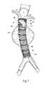
- FIG. 1is a perspective view of a prosthesis having a fastening region that accommodates the introduction of one or more fasteners.
- FIG. 2is a perspective view of the prosthesis shown in FIG. 1 , showing the attachment of fasteners in the fastening region.
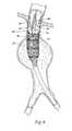
- FIG. 3is a perspective view of the prosthesis shown in FIG. 1 positioned within an abdominal aortic aneurysm.
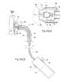
- FIG. 4is a perspective view of the prosthesis shown in FIG. 3 as it is being deployed by an intra-vascular catheter.
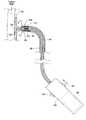
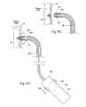
- FIG. 5is a perspective view of the prosthesis shown in FIG. 3 after it been deployed and as fasteners are being implanted by an intra-vascular fastener applier.
- FIG. 6is a side view, partly broken away and in section, of an intra-vascular fastener applier that can be used to implant fasteners in the prosthesis shown in FIGS. 1 and 2 , in the manner shown in FIG. 5 .
- FIG. 7is a perspective view of a type of helical fastener that can be implanted using the intra-vascular fastener applier shown in FIG. 6 .
- FIG. 8 A( 1 )is an enlarged view of a carrier for implanting a fastener of the type shown in FIG. 7 , the carrier being located at the distal end of an intra-vascular fastener applier of the type shown in FIG. 8 A( 2 ), the carrier being shown in a condition to receive a fastener prior to implantation.
- FIG. 8 A( 2 )is a side view, partly broken away and in section, of a fastener applier that includes, at its distal end, a carrier as shown in FIG. 8 A( 1 ), the carrier being shown after receipt of a fastener and as the carrier is being rotated to implant the fastener in a prosthesis/tissue wall.
- FIG. 8 B( 1 )is an enlarged view of the carrier shown in FIG. 8 A( 1 ), the carrier being shown in a condition to release a fastener after implantation.
- FIG. 8 B( 2 )is a side view, partly broken away and in section, of the fastener applier that includes, at its distal end, the carrier shown in FIG. 8 B( 1 ), the carrier being shown releasing a fastener following its implantation in a prosthesis/tissue wall.
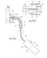
- FIG. 8Cis a side view, partly broken away and in section, of the fastener applier shown in FIG. 8 A( 2 ), the carrier being shown withdrawing or retrieving a fastener from a prosthesis/tissue wall.
- FIG. 9 A( 1 )is an enlarged view of another embodiment of a carrier for implanting a fastener of the type shown in FIG. 7 , the carrier being located at the distal end of an intra-vascular fastener applier of the type shown in FIG. 9 A( 2 ), the carrier being shown in a condition to receive a fastener prior to implantation.
- FIG. 9 A( 2 )is a side view, partly broken away and in section, of a fastener applier that includes, at its distal end, a carrier as shown in FIG. 9 A( 1 ), the carrier being shown after receipt of a fastener and as the carrier is being rotated to implant the fastener in a prosthesis/tissue wall.
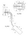
- FIG. 9 B( 1 )is an enlarged view of the carrier shown in FIG. 9 A( 1 ), the carrier being shown in a condition to release a fastener after implantation.
- FIG. 9 B( 2 )is a side view, partly broken away and in section, of the fastener applier that includes, at its distal end, the carrier shown in FIG. 9 B( 1 ), the carrier being shown releasing a fastener following its implantation in a prosthesis/tissue wall.
- FIG. 10 A( 1 )is an enlarged view of a carrier for implanting a fastener of the type shown in FIG. 7 , the carrier being located at the distal end of an intra-vascular fastener applier of the type shown in FIG. 10 A( 2 ), the carrier being shown in a condition to receive a fastener prior to implantation.
- FIG. 10 A( 2 )is a side view, partly broken away and in section, of a fastener applier that includes, at its distal end, a carrier as shown in FIG. 10 A( 1 ), the carrier being shown after receipt of a fastener and as the carrier is being rotated to implant the fastener in a prosthesis/tissue wall.
- FIG. 10 B( 1 )is an enlarged view of the carrier shown in FIG. 10 A( 1 ), the carrier being shown in a condition to release a fastener after implantation.
- FIG. 10 B( 2 )is a side view, partly broken away and in section, of the fastener applier that includes, at its distal end, the carrier shown in FIG. 10 B( 1 ), the carrier being shown releasing a fastener following its implantation in a prosthesis/tissue wall.
- FIG. 11is an enlarged view of a carrier for implanting a fastener of the type shown in FIG. 7 , the carrier being located at the distal end of an intra-vascular fastener applier of the type shown in FIGS. 10 A( 2 ) and 10 B( 2 ), the carrier being shown in a condition to receive a fastener prior to implantation.
- FIGS. 12A and 12Bare perspective views of a fastener assembly comprising a helical fastener and a cap, FIG. 12A showing an exploded view of the assembly and FIG. 12B showing an assembled view of the assembly.
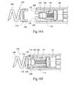
- FIGS. 13A and 13Bare side views showing in interior of a carrier for implanting a fastener assembly of the type shown in FIG. 12B , the carrier being located at the distal end of an intra-vascular fastener applier of the type shown in FIG. 15A , the carrier in FIG. 13A being shown in a condition to receive the fastener assembly prior to implantation, the carrier in FIG. 13B being shown in a condition to release the fastener assembly after implantation.
- FIGS. 14A and 14Bare side views showing the mounting of the fastener assembly shown in FIG. 12B to the carrier shown in FIG. 13A .
- FIG. 15Ais a side view, partly broken away and in section, of a fastener applier that includes, at its distal end, a carrier as shown in FIG. 13A , the carrier being shown after receipt of a fastener assembly as shown in FIG. 14B and as the carrier is being rotated to implant the fastener assembly in a prosthesis/tissue wall.
- FIG. 15Bis a side view, partly broken away and in section, of a fastener applier shown in FIG. 15A , the carrier being shown releasing the fastener assembly after its implantation in a prosthesis/tissue wall.
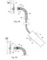
- FIG. 15Cis a side view, partly broken away and in section, of a fastener applier shown in FIG. 15A , the carrier being shown withdrawing or retrieving the fastener assembly from a prosthesis/tissue wall.
- FIG. 16 A( 1 )is an enlarged view of a carrier for implanting a fastener of the type shown in FIG. 7 , the carrier being located at the distal end of an intra-vascular fastener applier of the type shown in FIG. 16 A( 2 ), the carrier being shown holding a fastener prior to implantation.
- FIG. 16 A( 2 )is a side view, partly broken away and in section, of a fastener applier that includes, at its distal end, a carrier as shown in FIG. 16 A( 1 ), the carrier being rotated to implant the fastener in a prosthesis/tissue wall.
- FIG. 16Bis a side view, partly broken away and in section, of the fastener applier shown in FIG. 16 A( 2 ), the carrier being shown at the end of a first operating phase, during which the fastener has been partially implanted in a prosthesis/tissue wall and in which the fastener remains secured to the carrier.
- FIG. 16Cis a side view, partly broken away and in section, of the fastener applier shown in FIG. 16 A( 2 ), the carrier being shown following the first operating phase and at the end of a second operating phase, during which the fastener has been fully implanted and released from the carrier into a prosthesis/tissue wall.
- FIG. 16Dis a side view, partly broken away and in section, of the fastener applier shown in FIG. 16 A( 2 ), the carrier being shown following the first operating phase and during another operating phase, during which the fastener is being withdrawn or retrieved from a prosthesis/tissue wall while still secured to the carrier.
- FIGS. 17A and 17Bare side views of a fastener applier of the type shown in any of the preceding Figures, the fastener applier including an element releasably tethering a fastener to the fastener applier, FIG. 17A showing the tethering element holding on to the fastener following its implantation in a prosthesis/tissue wall, and FIG. 17B showing the tethering element after having been parted from the fastener.
- FIGS. 18A and 18Bshow an embodiment of a tethering element of the type shown in FIGS. 17A and 17B , the tethering element being secure to a frangible portion of the fastener, FIG. 18A showing the tethering element holding on to the fastener following its implantation in a prosthesis/tissue wall, and FIG. 18B showing the tethering element after having been parted from the fastener.
- FIG. 19Ashows an embodiment of a tethering element of the type shown in FIGS. 17A and 17B , the tethering element being secured to a frangible joint that is broken by rotating the tethering element relative to the fastener.
- FIG. 19Bshows an embodiment of a tethering element of the type shown in FIGS. 17A and 17B , the tethering element being secured to a frangible joint that is broken by pulling the tethering element from the fastener.
- FIGS. 20A and 20Bshow an embodiment of a tethering element of the type shown in FIGS. 17A and 17B , the tethering element being secured to a screw joint ( FIG. 20A ) that is parted by rotating the tethering element relative to the fastener ( FIG. 20B ).
- FIGS. 21A and 21Bshow an embodiment of a tethering element of the type shown in FIGS. 17A and 17B , the tethering element being secured to a ball joint ( FIG. 21A ) that is parted by pulling the tethering element away from the fastener ( FIG. 21B ).
- FIGS. 22A and 22Bshow an embodiment of a tethering element of the type shown in FIGS. 17A and 17B , the tethering element being secured to a slip joint ( FIG. 22A ) that is parted by pulling the tethering element away from the fastener ( FIG. 22B ).
- FIGS. 23A and 23Bshow an embodiment of a tethering element of the type shown in FIGS. 17A and 17B , the tethering element being secured to a knotted joint ( FIG. 23A ) that is parted by pulling the tethering element away from the fastener ( FIG. 23B ).
- FIGS. 24A and 24Bshow an embodiment of a tethering element of the type shown in FIGS. 17A and 17B , the tethering element being secured to a frangible tube joint ( FIG. 24A ) that is parted by pulling a rip cord ( FIG. 24B ).
- FIGS. 25A and 25Bshow an embodiment of a tethering element of the type shown in FIGS. 17A and 17B , the tethering element being secured by an interlocking joint ( FIG. 25A ) that is released by pulling away a slidable sleeve ( FIG. 25B ).
- FIG. 1shows a prosthesis 10 .
- the prosthesis 10serves to repair or reinforce a region of a vessel wall or hollow body organ which has been weakened by disease or damage.
- the prosthesis 10comprises a tubular trunk 12 .
- the trunk 12is sized and configured to fit within a targeted region of a hollow body organ and/or a blood vessel.
- the targeted regionis selected on the basis of certain anatomic characteristics. These characteristics include a weakened conditioned caused, e.g., by disease or damage.
- the trunk 12forms a generally cylindrical structure with an open interior lumen 18 .
- the trunk 12includes a prosthetic material 14 supported by a scaffold 16 .
- the prosthetic material 14is selected on the basis of its biocompatibility, durability, and flexible mechanical properties.
- the material 14can comprise, e.g., woven polyester or ePTFE.
- the scaffold 16is desirable sized and configured to permit non-invasive deployment of the prosthesis 10 by an intra-vascular catheter.
- the scaffold 16is sized and configured to assume a compressed or collapsed, low profile condition, to permit its intra-vascular introduction into the hollow body organ and/or blood vessel by a catheter, as will be described in greater detail later.
- the scaffold 16is sized and configured for expansion in situ from its collapsed condition into an expanded condition in contact with tissue in the targeted region, as will also be described in greater detail later.
- the scaffold 16can comprise, e.g., a malleable plastic or metal material that expands in the presence of an applied force.
- the deployment cathetercan include, e.g., an expandable body, such as a balloon, to apply the expansion force to the scaffold 16 in situ.
- the scaffold 16can comprise a self-expanding plastic or metal material that can be compressed in the presence of a force, but self-expands upon removal of the compressive force.
- the deployment cathetercan include, e.g., a sleeve that can be manipulated to enclosed the scaffold 16 in a collapsed condition, thereby applying the compressive force, and to release the scaffold 16 when desired to allow the scaffold 16 to self-expand in situ.
- the scaffold 16can include individual self-expanding, zigzag type main scent rings 22 .
- the main stent rings 22can be made, e.g., from Nitinol® wire. Still, other materials, manufacturing methods and designs can be used.
- the main stent rings 22need not be attached to one another throughout the prosthesis material 14 , as FIG. 1 shows.
- the individual main stent rings 22allow for longitudinal compliance while maintaining radial support of the open interior lumen 18 . This technical feature allows the prosthesis 10 to more readily accommodate changes in morphology in the targeted region. Still, it may be desirable in certain locations within the prosthesis structure to have attachments between the individual main stent rings 22 to provide enhanced stability and/or additional radial support.
- Each of the main stent rings 22can be, e.g., sewn onto prosthetic material 14 .
- the attachment of the main scent rings 22can be made, e.g., with polyester suture.
- attachment meanscould be utilized to secure the main stent rings 22 to the prosthetic material 14 .
- These meansinclude bonding; capturing the main stent rings 22 between two layers of prosthetic material 14 ; and incorporating the main stent rings 22 directly into the prosthetic material 14 .
- main stent rings 22In certain locations it is desired to have the main stent rings 22 attached to the outer diameter of the prosthetic material 14 . Still, it is also contemplated that the main stent rings 22 could be attached to the inner diameter of the prosthetic material 22 .
- one end of the trunk 12desirably also includes one or more end stent rings 24 .
- the principal purpose of an end stent ring 24is to provide a seal between the trunk 12 and adjoining tissue. This sealing function is particularly desirable when the prosthesis 10 is deployed in a blood vessel or other body organ, where body fluids are intended to reside or pass through the prosthesis 10 .
- the end sent rings 24can also serve, with the main stent rings 22 , to help maintain the position of the prosthesis 10 in the targeted region.
- the trunk 12(material 14 and/or scaffold 16 ) can carry radiopaque markers 46 to help fluoroscopically position the prosthesis 10 .
- the markers 46can take the form, e.g. of marker bands, tight wound coils, or wire made from radiopaque materials such as platinum, platinum/iridium, or gold.
- the trunk 12also desirably includes at least one fastening region 26 that accommodates the introduction of one or more fasteners 28 to anchor the prosthesis 10 in place (see FIG. 2 ). It is desirable that this region 26 of the trunk 12 be specially sized and configured for the receipt and retention of fasteners 28 .
- the size and spacing of ring stent patternscan be configured in the region 26 to specially accommodate the placement of fasteners; and/or woven fibers with an “X-pattern” or a “sinusoidal pattern” can be used in the region 26 to specially accommodate placement of fasteners; and/or the prosthetic material 14 can be folded-over to form multiple layers, to reinforce the prosthesis in the region 26 where fasteners are placed; and/or denser weave patterns or stronger fibers can be used, selected from, e.g., KevlarTM material or VectranTM material or metallic wire woven alone or interwoven with typical polyester fibers in the region 26 were fasteners are placed. It may also be desirable to fluoroscopically indicate this region 26 with auxiliary radiopaque markers 30 on the prosthetic material 14 , and/or auxiliary stent rings 32 to aid in positioning the fasteners.
- the fasteners 28can be variously constructed. They can, e.g., comprise helical fasteners or staples.
- the fasteners 28are introduced by an intra-vascular fastener attachment assembly. Details of various fastener attachment assemblies will be described in greater detail later.
- the targeted region for deployment of the tissue reinforcement prosthesis 10 as just describedcan vary.
- the trunk 12is sized and configured to extend, for purposes of illustration, in the aorta adjacent the renal arteries distally to a location proximal the natural bifurcation of the iliac arteries.
- this targeted site of deploymentis selected for purposes of illustrating the features of the prosthesis 10 , and it is not intended to be limiting.
- the fastening region 26is located in the neck of the aorta adjacent to the renal arteries.
- the features of the fastening region 26previously described, make possible the secure attachment of the prosthesis 10 , without migration.
- the trunk 12may include a supra-renal stent 44 at its proximal end, which extends beyond the prosthetic material 14 .
- this stent 44When deployed within the aorta, this stent 44 would extend above the level of the renal arteries, as FIG. 3 shows.
- the supra-renal stent 44orients the prosthesis 10 within the lumen and aids in maintaining the position of the prosthesis 10 in the aorta without obstructing the normal blood flow into the renal arteries.
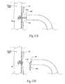
- a first catheter 20is navigated over a guide wire 48 through an iliac to the desired location within the aorta near the renal arteries.
- the catheter 20carries the prosthesis 10 in a radially reduced configuration.
- the catheter 20releases the prosthesis 10 , which expands radially into the position shown in FIG. 5 .
- a fastener assembly 34is next deployed (which is shown generally in FIG. 5 ) to place fasteners 28 into the fastening region 26 of the trunk 12 .
- the prosthesis 10is thereby secured in position.
- the fastener assembly 34can be variously constructed and configured.
- the fastener attachment assembly 34comprises a fastener guide component 36 and a fastener applier component 38 .
- the guide component 36can comprise, e.g., a guide sheath that desirably has a steerable or deflectable distal tip.
- the guide component 36can be initially deployed over the guidewire that is used to deliver and position the prosthesis 10 .
- the guide wirecan be withdrawn after the guide component 36 is deployed and positioned, so that the applier component 38 can be introduced.
- the applier component 38is desirably deployed through the guide component 36 .
- a fastener drive mechanism 40 on the fastener applier component 38carries at least one fastener 28 .
- the fastener drive mechanism 40advances the fastener 28 , causing it to penetrate the prosthesis 10 and underlying tissue wall. In this way, the fastener anchors the prosthesis 10 firmly in place.
- the fastener applier 38comprises a catheter 42 .
- the catheter 42carries the fastener drive mechanism 40 at its distal tip.
- the fastener drive mechanism 40comprises carrier 50 .
- the carrier 50is sized and configured to carry a selected fastener 28 .
- the fastener drive mechanism 40also includes a driver 52 , which is coupled to impart movement to the carrier 50 .
- the driver 52 and carrier 50can comprise an integrated unit, with the carrier 50 being formed on the distal end of the driver 52 , as shown, or they can comprise separate components, e.g., with the driver comprising a clutch or the like for the carrier 50 .
- the driven movementdeploys the fastener 28 .
- the type of driven movement that is imparteddepends upon the type of fastener 28 that is used.
- the fastener 28comprises is an open helical coil 54 with a sharpened leading tip 56 .
- This type of helical fasteneris deployed into tissue by rotational movement. Consequently, rotational movement is imparted by the driver 52 to the carrier 50 , which is sized and configured to carry the fastener shown in FIG. 7 .
- the actuation of the driver 52can, of course, be accomplished in various ways, e.g., mechanical (i.e., manual or hand-powered), electrical, hydraulic, or pneumatic.
- a drive motor 58imparts rotation to the driver 52 through a drive cable 60 .
- the drive motor 58is housed in a handle 62 , which is carried at the proximal end of the catheter 42 .
- the drive cable 60extends from the handle 62 , through the catheter 42 , and couples to the driver 52 at the distal end of the catheter 42 .
- the drive cable 60is desirably made of a suitable material that allows for both bending and rotation.
- Activation of the drive motor 58(e.g., by a physician controlled switch 64 on the handle 62 ) rotates, as a unit, the drive shaft 60 , the driver 52 , the carrier 50 , and the fastener 28 in the carrier 50 .
- the rotational movementcauses the helical fastener 28 to travel into the prosthesis 10 and the tissue wall.
- the implantation force of the fastener drive mechanism 40is desirably resolved in some manner to provide positional stability and resist unintended movement of the carrier 50 relative to the implantation site.
- a resolution forceis desirably applied to counteract and/or oppose the implantation force of the fastener drive mechanism 40 . It is desirable to resolve some or all or a substantial portion of the implantation force within the vessel lumen (or other hollow body organ) itself, and preferably as close to the implantation site as possible.
- the tubular body of the guide component 36 and/or the shaft of the catheter 42can be sized and configured to possess sufficient column strength to resolve some or all or at least a portion of the implantation force within the vessel lumen or hollow body organ.
- FIG. 5shows the guide component 36 braced against the vessel wall to apply a counterbalancing resolution force.
- the guide component 36 and/or the fastener applier component 38can include some form of stabilization means for applying a counteracting force at or near the carrier 50 .
- stabilization meansare disclosed in co-pending U.S. patent application Ser. No. 10/669,881, filed Sep. 24, 2003, and entitled “Catheter-Based Fastener Implantation Apparatus and Methods with Implantation Force Resolution.”
- the carrier 50itself can be various constructed, as can the fastener 28 to facilitate its coupling to the carrier 50 . Representative embodiments will now be described.
- the proximal end of the fastener 28desirably includes a fitting 66 that, in use, couples the fastener 28 to the carrier 50 .
- the fitting 66comprises an L-shaped brace or leg 66 .
- the L-shape leg 66desirably bisects the entire interior diameter of the coil 54 ; that is, the L-shaped leg 66 extends completely across the interior diameter of the coil 54 , as FIG. 7 shows.
- the carrier 50is sized and configured to engage the fitting 66 , i.e., L-shaped leg 66 , to thereby impart rotation to the helical fastener 28 to achieve implantation.
- the L-shaped leg 66also serves as a stop to prevent the helical fastener 28 from penetrating too far into the tissue.
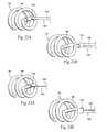
- the carrier 50(see FIGS. 8 A( 1 ) and 8 A( 2 )) includes a fastener support element 68 that permits the selective release of the fastener 28 .
- the support element 68has at least two operating conditions.
- a first conditionsee FIG. 8 A( 1 )
- the support element 68engages the L-shaped leg 66 of the fastener 28 to hold the fastener 28 on the carrier 50 .
- rotation of the carrier 50imparts rotation to the fastener 28 (as shown by the rotational arrow in FIG. 8 A( 2 ), to allow implantation of the fastener 28 into the prosthesis 10 /tissue wall without releasing the fastener 28 (i.e., in response to rotation in one direction, as FIG. 8 A( 2 ) shows), as well as allow the withdrawal the fastener 28 from the prosthesis 10 /tissue wall without releasing the fastener 28 (i.e., in response to rotation in an opposite direction, as FIG. 8C shows).
- the support element 68releases the fastener 28 .
- the fastener 28 and the carrier 50can be separated. Release of the fastener 28 from the carrier 50 can be and desirably is accomplished without rotation of the carrier 50 . It is desirable that the support element 68 can affect separation of the fastener 28 while the carrier 50 is stationary and not rotating.
- the support element 68therefore differentiates the step of operating the carrier 50 to implant the fastener 28 (by rotation of the carrier 59 with the support element 68 in its first condition) from the step of releasing the fastener 28 from the carrier 50 (by placing the support element 68 in its second condition, which is desirably achieved independent of rotation of the carrier 50 ).
- the support element 68thereby also makes possible the use of the carrier 50 to withdraw the fastener 28 from tissue and to retrieve or reposition the fastener 28 , if desired.
- Operation of the support element 68 independent of operation of the carrier 50makes possible the release of the fastener 28 from the carrier 50 in a separate releasing step, which can be delayed to assure that implantation of the fastener 28 has been satisfactorily completed.
- the support element 68 just describedcan be achieved by the use of various structural embodiments.
- the support elementtakes the form of hinged gripping jaws 70 on the distal end of the carrier 50 .
- the gripping jaws 70are moveable between a mutually closed condition (i.e., the first condition, as shown in FIG. 8 A( 1 )) and a mutually opened condition (i.e., the second condition, as shown in FIG. 8 B( 1 )).
- the L-shaped leg 66 of the fastener 28is gripped by interference fit within a receptacle 72 formed between the jaws 70 when the jaws 70 are mutually closed, as FIGS.
- FIGS. 8 A( 1 ) and 8 A( 2 )show.
- the receptacle 72opens and frees the L-shaped leg 66 when the gripping jaws 70 are mutually opened, as FIGS. 8 B( 1 ) and 8 B( 2 ) show.
- a physician-manipulated actuator 74selectively pivots the hinged gripping jaws 70 from their mutually closed condition to their mutually opened condition.
- the actuator 74comprises a pull cable 76 or stylet, which is coupled at its proximal end to a controller 78 on the handle (see FIGS. 8 A( 2 ) and 8 B( 2 )).
- the pull cable 76extends through the catheter 42 and terminates at its distal end with a shaped cam element 78 .
- the cam element 78 in the illustrated embodimentis ball-shaped. It occupies the area defined between tapered, facing cam surfaces 80 formed on the interior of the gripping jaws 70 .
- the hinged gripping jaws 70are desirably biased toward the mutually closed condition.
- a springcan be used for the purpose.
- the gripping jaws 70are formed by machining or molding from an elastic, spring-like material (metal or plastic).
- the formed materialincludes an integral hinge 82 , which normally biases the gripping jaws 70 closed.
- the hinge 82yields to the force applied by the cam element 78 against the cam surfaces 80 , but returns the jaws 70 to their mutually closed condition in the absence of the force.
- a physiciancan snap fit the L-shaped leg 66 of a fastener 28 into the receptacle 72 between the gripping jaws 70 at time of use. The snap fit provides tactile assurance that the fastener 28 has been properly engaged within the receptacle 72 of the gripping jaws 70 .
- the support element 68takes the form of spring-biased struts 84 on the carrier 50 .
- the struts 84resiliently open to accommodate snap-fit passage of the L-shaped leg 66 into a retaining space 87 between the struts 84 , allowing the coil 54 of the fastener 28 to nest upon the struts 84 (as FIG. 9 A( 2 ) shows).
- the resilient, normally closed condition of the struts 84comprises the first operating condition, which holds the fastener 28 on the struts 84 , thereby securing the fastener 28 to the carrier 50 . In this condition, rotation of the carrier 50 rotates the fastener 28 , to allow implantation of the fastener 28 into tissue and/or withdrawal of the fastener 28 from tissue.
- a physician-manipulated actuator 86comprising, e.g., a push cable or stylet
- a controller 88 on the handle 62can be advanced forward through the catheter by operation of a controller 88 on the handle 62 .
- the carrier 50need not be and desirably is not rotated during this operation.
- the push cable 86when advanced (see FIGS. 8 B( 1 ) and 8 B( 2 ), contacts the L-shaped leg 66 and urges the leg 66 out of the retaining space 87 against the resiliently closed struts 84 .
- the struts 84are resiliently displaced by force of the L-shaped leg 66 , which are caused to assume a temporary, mutually opened condition.
- the fastener 28can thereby be ejected from the carrier 50 .
- the support element 68may include normally open struts 90 that define a receptacle 92 and include a detent 94 that governs passage of the L-shaped leg 66 into and out of the receptacle 92 .
- a physician-manipulated actuator 96comprising, e.g., a push-pull cable or stylet, can be advanced fore and aft through the catheter 42 into and out of contact with the detent 94 , e.g., by operation of a controller 98 on the handle 62 (see FIGS. 10 A( 2 ) and 10 (B)( 2 )).
- the cable 96when advanced into contact with detent 94 (see FIG. 10 A( 1 )( 1 )) locks the detent 94 in a position projecting into the receptacle 92 .
- the detent 94when locked, blocks entry into or out of the receptacle 92 .
- the cable 96when withdrawn from contact with detent 94 , unlocks the detent 94 , and allows movement of the detent 94 out of the position blocking the receptacle 92 .
- the detent 94when unlocked (see FIGS. 10 A( 1 ) and 10 A( 2 )), accommodates passage of the L-shaped leg 66 into the retainer 92 between the struts 90 , while the remainder of the fastener 28 nests upon the struts 90 .
- the fastener 28can be loaded onto the carrier 50 in this fashion.
- the subsequent locking of the detent 94blocks release of the L-shaped leg 66 , securing the fastener 28 to the carrier 50 .
- the cable 96when advanced out of contact with detent 94 , unlocks the detent 94 (see FIGS. 10 B( 1 ) and 10 B( 2 )).
- the carrier 50need not be and desirable is not rotated during this operation. This allows passage of the L-shaped leg 66 past the detent 94 and free of the receptacle 92 , as previously described, in response to aft movement of the catheter 42 and attached carrier 50 .
- the detent 94may be biased by a spring 100 toward a normally projecting condition to serve the same function.
- the fastener 28takes the form of a fastener cap assembly 102 that is releasably fitted onto a specially adapted carrier 104 (see FIGS. 14A and 14B ) at time of use.
- the fastener cap assembly 102includes a helical fastener 106 on which a proximal cap 108 is mounted.
- the cap 108can comprise a plastic, metal, or ceramic biocompatible material.
- the cap 108can be secured to the proximal end of the fastener 206 , e.g., by adhesives, machining, molding, or welding.
- the cap 108includes preformed side mounts 110 .
- the cap 108serves the same general function as the L-shaped leg 66 shown in FIG. 7 , i.e., it is a fitting secured to the fastener that enables the coupling of the fastener 28 to the carrier.
- the carrier 104includes an attachment mechanism 112 , which will be described in greater detail later.
- the attachment mechanism 112is sized and configured to engage the mounts 110 , to thereby couple the fastener assembly 102 to the carrier 104 at time of use.
- the attachment mechanism 112imparts rotation to the fastener assembly 102 when the carrier 104 is rotated (see FIG. 15A ) to achieve implantation of the fastener assembly 102 into the prosthesis 10 /tissue wall without releasing the fastener assembly 102 (i.e., in response to rotation of the carrier 104 in one direction, as FIG. 15A shows).
- the attachment mechanism 112can also withdraw the fastener assembly 102 from the prosthesis 10 /tissue wall (see FIG. 15C ) without releasing the fastener assembly 102 (i.e., in response to rotation of the carrier 104 in an opposite direction, as FIG. 15C shows).
- the carrier 104also includes a release mechanism 114 , as will be described in greater detail later.
- the release mechanism 114selectively releases the fastener assembly 102 from the attachment mechanism 112 (see FIG. 15B ). Release of the fastener assembly 102 from the attachment mechanism 112 can be and desirably is accomplished without rotation of the carrier 104 .
- the carrier 104 with an attachment mechanism 112 to which a fastener assembly 102 can be fitted at time of use, as well as an independent, selectively operable release mechanism 114allows a physician to operate the carrier 104 to implant the fastener assembly 102 separate from the step of releasing the fastener assembly 102 after implantation has been accomplished.
- the carrier 104 with a selective release for the fastener assembly 102also makes possible the withdrawal the fastener assembly 102 from tissue and the retrieval and/or reposition the fastener assembly 104 , if desired, while the carrier 104 remains secured to the fastener assembly 102 . In this arrangement, release of the fastener assembly 102 from the carrier 104 can be accomplished once fastener assembly 102 has been satisfactorily implanted, or otherwise at a time controlled by the operator.
- the attachment mechanism 112comprises a pair of gripper arms 116 coupled to the driver 52 .
- the gripper arms 116can be made by machining or molding from a metal or plastic material.
- the gripper arms 116can be normally biased toward an inwardly deflected condition. The bias can be achieved, e.g., by imparting a spring memory to the arms 116 .
- the arms 116need not be biased inwardly, but instead include outside edges that are inclined, as FIG. 13B shows.
- the armsinclude outwardly projecting tabs 126 that are sized to snap into mounts 110 on the cap 108 (as FIG. 14B shows).
- the release mechanism 114comprises a spacer rod 118 extends between the gripper arms 116 .
- the rod 118carries at its distal end a cam element 120 .
- the gripper arms 116When withdrawn from contact with the gripper arms 116 (as FIG. 13B shows), the gripper arms 116 are positioned such that the tabs 126 will snap into the mounts 110 on the cap 108 , as FIG. 14A shows.
- the cam element 120when disposed in contact with the gripper arms 116 (as shown in FIG. 13A ), spreads the gripper arms 116 apart, into an outwardly deflected condition, locking the tabs 116 into the mounts 110 , as FIG. 14B shows.
- a spring 122normally urges the cam element 120 toward contact with the gripper arms 116 (as shown in FIGS. 13A and 14B ).
- the rod 118when pulled aft (as FIGS. 13B and 14A show) withdraws the cam element 120 , and the gripper arms 116 are positioned to receive the cap 108 .
- the rod 118extends through the catheter 42 and is coupled to a controller 124 on the handle 62 (see FIGS. 15A and 15B ).
- the tabs 126lock into the mounts 110 on the fastener cap 108 , securing the fastener assembly 102 to the carrier 104 . Conversely, when the cam element 120 is withdrawn, the tabs 126 allow the fastener assembly 102 to be inserted onto or separated from the carrier 104 .
- the physicianpulls back on the control 124 to withdraw the cam element 120 against the bias of the spring 122 and snap-fits a fastener assembly 102 onto the carrier 104 .
- the physicianthen releases the control 124 to allow the spring 122 to return forward and lock the fastener assembly 102 onto the carrier 104 .
- the physicianthen deploys the catheter 42 holding the fastener assembly 102 to the targeted site (see FIG. 15A ). By rotating the carrier 104 , the physician implants the fastener assembly 102 into the prosthesis 10 /tissue wall.
- the physicianpulls back on the control 124 and the catheter 42 (see FIG. 15B ) to separate the fastener assembly 102 from the carrier 104 .
- the physicianwithdraws the catheter 42 and repeats the forgoing steps until the desired number of fastener assemblies 102 has been implanted.
- the above-described embodimentsprovide the ability to withdraw a given fastener from a prosthesis/tissue wall prior to completion of the implantation step.
- the above-described embodimentsmake this feature possible by providing a fastener applier 38 that includes a fastener release mechanism that works independent of the fastener implantation mechanism.
- a fastener applier 38includes a fastener carrier 128 that implements this feature without an independent release mechanism.
- the fastener carrier 128is operated in two phases. The first or initial phase advances a fastener 28 into an incomplete implantation position within a prosthesis 10 /tissue wall ( FIG. 16B ), which represents a sufficient distance to gain purchase, but which is short of full implantation.
- the fastener 28remains coupled to the fastener carrier 128 , to allow the physician to operate the fastener carrier 128 to withdraw/retrieve the fastener 28 , if desired (see FIG. 16D ).
- the first phasepresents a decision point to the physician.
- a lull phaseexists, during which operation of the fastener carrier 128 is interrupted.
- a prescribed input commandis required to move out of the lull phase.
- the physiciancan elect to withdraw or retrieve the fastener 28 ( FIG. 160 ).
- the physiciancan elect to continue implantation and proceed to the second phase.
- the fastener carrier 128advances the fastener 28 from the incomplete implantation position ( FIG. 16B ) to the complete implantation position ( FIG. 16C ), at the end of which the fastener 28 itself automatically separates from the fastener carrier 128 . That is, during the second phase, implantation force is applied to the fastener 28 under conditions that supplement the conditions of the first phase in order to meet the conditions prescribed for full implantation.
- the fastener applier 38can implement this feature in various structural embodiments.
- the carrier 128coupled to a driver 52 , includes a slot 130 , which receives the L-shaped leg 66 to couple the fastener 28 for rotation with the carrier 128 .
- the turns of the coil 54rest in complementary internal grooves 132 that surround the carrier 128 .
- the grooves 132could be positioned along the entire length of the fastener 28 or within a portion of its length.
- Activation of the drive mechanismrotates, as a unit, the driver 52 , the carrier 128 , and the helical fastener 28 (as FIG. 16 A( 2 ) shows).
- This rotationcauses the helical fastener 28 to travel within the internal grooves 132 of the fastener applier and into the prosthesis 10 and tissue wall. Uninterrupted rotation of the carrier 128 will cause the helical fastener 28 to be rotated completely off the carrier and through the prosthesis 10 and into the tissue wall (as FIG. 16C shows).
- the drive mechanismincludes a motor control unit 134 (see FIGS. 16 A( 2 ), 168 , and 16 D).
- the motor control unit 134is conditioned to operate the carrier 128 in the two distinct phases, as above described.
- the first phase of fastener implantationis initiated by the physician activating a rotation command, e.g., by manipulating a first switch 136 on the handle 62 .
- the carrier 128is driven sufficient to rotate the helical fastener 28 to a position in which the distal portion of the fastener 28 has implanted itself into the target tissue, but in which the proximal portion of the fastener 28 is still retained within the internal threads 132 of the carrier 128 .
- the motor control unit 134enters the lull phase, automatically interrupting rotation of the carrier 128 .
- the motor control unit 134can accomplish motor control in this fashion by either conventional mechanical and or electronic means, e.g., through a programmable microprocessor.
- the physicianhas the option of reversing the insertion process and removing the fastener 28 , if desired (see FIG. 16D ), e.g., by reversing the switch 136 or activating another switch 138 on the handle 62 .
- the physicianalso has the option of completing the implantation process, e.g., by manipulating the switch 136 in a preprogrammed fashion (for example, by double switching).
- the motor control unit 136can receive input reflecting a performance criteria measured during the first phase of deployment.
- the motor control unit 136assesses the value of the performance criteria, to determine whether it falls within a predetermined acceptable range. If so, the second phase of deployment may occur automatically without a pause and without a second input from the user.
- motor current used during the first phase of fastener deploymentcould be measured, and from this the fastener driving torque could be calculated.
- a torque within a range of acceptable valueswould imply that the fastener 28 had successfully entered the target tissue and fastener implantation could be completed automatically.
- a torque that was outside the acceptable rangecould result in either a pause at the end of phase one, where the user could make the decision to continue or reverse the fastener deployment, or an automatic reversal of fastener deployment.
- a fastener release mechanism 114 of the type shown, e.g., in FIGS. 13 A/B and 14 A/Bcan be used in association with a motor control unit 134 .
- the motor control unit 134is conditioned to operate the carrier 104 to drive the fastener assembly 102 in a single phase of deployment into tissue.
- the release mechanism 114can be operated in the manner previously described, to separate the fastener assembly 102 from the carrier 104 .
- the motor control unit 134can be conditioned by mechanical and/or electronic means to indicate and/or control the number of revolutions and/or the torque applied to accomplish the installation of the fastener assembly 102 in tissue. In this embodiment, there is no need for multiple phases, because the physician ultimately controls the release of the fastener assembly 102 by manipulation of the release mechanism 114 .
- a fastener applier 38can include an element 140 to releasably tether a fastener 28 to the applier 38 even after the fastener 28 has been separated from the applier 38 (see FIG. 17A ).
- the tether element 140serves as a “life line,” maintaining a connection of last resort between the applier 38 and a fastener 28 .
- the tether element 28allows the fastener 28 to be retrieved if, for any reason, the fastener 28 inadvertently breaks loose from tissue and/or the applier 38 during or after implantation.
- the connection between the tether element 140 and the applier 38requires a deliberate act of the physician to be broken, adding a confirming, final step to the implantation process (see FIG. 17B ).
- the tether element 140can be variously constructed.
- the tether element 140comprises a thread, braid, wire, or tubing structure 142 .
- the proximal end of the tether element structure 142is attached to the fastener applier 38 in a manner that can be detached by application of a deliberate pulling force.
- the distal end of the tether element structure 142is frangible and can be broken by a force less than the deliberate pulling force once desired deployment of the fastener 28 is confirmed, as FIG. 17B shows.
- the tether element structure 142has sufficient length to be able to retract the fastener applier 38 enough to visualize the fastener in position (as FIG. 17A shows).
- the force to break the frangible distal end of the tether element structure 142is less than the force required to dislodge the fastener 28 from tissue. Desirably, the frangible distal end of the tether element structure 142 detaches from the fastener 28 without leaving remnants on the fastener 28 (as FIG. 17B shows).
- the tether element structure 142can be sized and configured in other, different ways to form a frangible connection with a fastener 28 .
- the L-shaped leg 66could be crimped to form an area of weakness 144 ( FIG. 18A ), to which the tether element structure 142 applies force to free the tether element structure 142 from the fastener 28 ( FIG. 18B ).
- the junction between the tether element structure 142 and the fastener 28can comprise an area of weakness 146 (e.g., by melding, soldering, gluing, heating, or shearing) that is broken by the application of a prescribed force in a prescribed manner, e.g., by rotation ( FIG. 19A ) or pulling ( FIG. 19B ).
- the junction between the tether element structure 142 and the fastener 28may comprise a threaded joint 146 (see FIGS. 20A and 20B ); or a snap-fit ball and socket joint 148 (see FIGS. 21A and 21B ); or a slide-fit joint 150 (see FIGS.
- the junction between the tether element 140 and the fastener 28can comprise an interlocking mechanism 160 , for example, a slidable outer sleeve 162 that, when advanced ( FIG. 25A ), captures an appendage 164 on the fastener 28 and, when retracted ( FIG. 25B ), frees the appendage 164 .
- an interlocking mechanism 160for example, a slidable outer sleeve 162 that, when advanced ( FIG. 25A ), captures an appendage 164 on the fastener 28 and, when retracted ( FIG. 25B ), frees the appendage 164 .
Landscapes
- Health & Medical Sciences (AREA)
- Life Sciences & Earth Sciences (AREA)
- Surgery (AREA)
- General Health & Medical Sciences (AREA)
- Public Health (AREA)
- Biomedical Technology (AREA)
- Heart & Thoracic Surgery (AREA)
- Veterinary Medicine (AREA)
- Engineering & Computer Science (AREA)
- Animal Behavior & Ethology (AREA)
- Molecular Biology (AREA)
- Nuclear Medicine, Radiotherapy & Molecular Imaging (AREA)
- Medical Informatics (AREA)
- Gastroenterology & Hepatology (AREA)
- Pulmonology (AREA)
- Cardiology (AREA)
- Oral & Maxillofacial Surgery (AREA)
- Transplantation (AREA)
- Vascular Medicine (AREA)
- Prostheses (AREA)
- Surgical Instruments (AREA)
- Media Introduction/Drainage Providing Device (AREA)
Abstract
Description
Claims (13)
Priority Applications (3)
| Application Number | Priority Date | Filing Date | Title |
|---|---|---|---|
| US13/495,836US8685044B2 (en) | 2001-11-28 | 2012-06-13 | Systems and methods for attaching a prosthesis with a body lumen or hollow organ |
| US14/210,683US9808250B2 (en) | 2001-11-28 | 2014-03-14 | Systems and methods for attaching a prosthesis within a body lumen or hollow organ |
| US15/611,596US10595867B2 (en) | 2001-11-28 | 2017-06-01 | Systems and methods for attaching a prosthesis within a body lumen or hollow organ |
Applications Claiming Priority (7)
| Application Number | Priority Date | Filing Date | Title |
|---|---|---|---|
| US33393701P | 2001-11-28 | 2001-11-28 | |
| US10/271,334US6960217B2 (en) | 2001-11-28 | 2002-10-15 | Endovascular aneurysm repair system |
| US10/307,226US8075570B2 (en) | 2001-11-28 | 2002-11-29 | Intraluminal prosthesis attachment systems and methods |
| US48901103P | 2003-07-21 | 2003-07-21 | |
| US10/693,255US6929661B2 (en) | 2001-11-28 | 2003-10-24 | Multi-lumen prosthesis systems and methods |
| US10/786,465US8231639B2 (en) | 2001-11-28 | 2004-02-25 | Systems and methods for attaching a prosthesis within a body lumen or hollow organ |
| US13/495,836US8685044B2 (en) | 2001-11-28 | 2012-06-13 | Systems and methods for attaching a prosthesis with a body lumen or hollow organ |
Related Parent Applications (1)
| Application Number | Title | Priority Date | Filing Date |
|---|---|---|---|
| US10/786,465ContinuationUS8231639B2 (en) | 2001-11-28 | 2004-02-25 | Systems and methods for attaching a prosthesis within a body lumen or hollow organ |
Related Child Applications (1)
| Application Number | Title | Priority Date | Filing Date |
|---|---|---|---|
| US14/210,683ContinuationUS9808250B2 (en) | 2001-11-28 | 2014-03-14 | Systems and methods for attaching a prosthesis within a body lumen or hollow organ |
Publications (2)
| Publication Number | Publication Date |
|---|---|
| US20120316578A1 US20120316578A1 (en) | 2012-12-13 |
| US8685044B2true US8685044B2 (en) | 2014-04-01 |
Family
ID=34861777
Family Applications (4)
| Application Number | Title | Priority Date | Filing Date |
|---|---|---|---|
| US10/786,465Expired - LifetimeUS8231639B2 (en) | 2001-11-28 | 2004-02-25 | Systems and methods for attaching a prosthesis within a body lumen or hollow organ |
| US13/495,836Expired - LifetimeUS8685044B2 (en) | 2001-11-28 | 2012-06-13 | Systems and methods for attaching a prosthesis with a body lumen or hollow organ |
| US14/210,683Expired - LifetimeUS9808250B2 (en) | 2001-11-28 | 2014-03-14 | Systems and methods for attaching a prosthesis within a body lumen or hollow organ |
| US15/611,596Expired - Fee RelatedUS10595867B2 (en) | 2001-11-28 | 2017-06-01 | Systems and methods for attaching a prosthesis within a body lumen or hollow organ |
Family Applications Before (1)
| Application Number | Title | Priority Date | Filing Date |
|---|---|---|---|
| US10/786,465Expired - LifetimeUS8231639B2 (en) | 2001-11-28 | 2004-02-25 | Systems and methods for attaching a prosthesis within a body lumen or hollow organ |
Family Applications After (2)
| Application Number | Title | Priority Date | Filing Date |
|---|---|---|---|
| US14/210,683Expired - LifetimeUS9808250B2 (en) | 2001-11-28 | 2014-03-14 | Systems and methods for attaching a prosthesis within a body lumen or hollow organ |
| US15/611,596Expired - Fee RelatedUS10595867B2 (en) | 2001-11-28 | 2017-06-01 | Systems and methods for attaching a prosthesis within a body lumen or hollow organ |
Country Status (7)
| Country | Link |
|---|---|
| US (4) | US8231639B2 (en) |
| EP (1) | EP1725172B1 (en) |
| JP (2) | JP4699445B2 (en) |
| CN (2) | CN101460104B (en) |
| AU (1) | AU2005216164A1 (en) |
| CA (1) | CA2554022C (en) |
| WO (1) | WO2005081936A2 (en) |
Cited By (36)
| Publication number | Priority date | Publication date | Assignee | Title |
|---|---|---|---|---|
| US20060100640A1 (en)* | 2001-11-28 | 2006-05-11 | Aptus Endosystems, Inc. | Devices, system, and methods for guiding an operative tool into an interior body region |
| US20090082852A1 (en)* | 2001-06-04 | 2009-03-26 | Aptus Endosystems, Inc. | Catheter-based fastener implantation apparatus and methods |
| US20090099650A1 (en)* | 2001-11-28 | 2009-04-16 | Lee Bolduc | Devices, systems, and methods for endovascular staple and/or prosthesis delivery and implantation |
| US20110087320A1 (en)* | 2001-11-28 | 2011-04-14 | Aptus Endosystems, Inc. | Devices, Systems, and Methods for Prosthesis Delivery and Implantation, Including a Prosthesis Assembly |
| US20110238088A1 (en)* | 2001-11-28 | 2011-09-29 | Aptus Endosystems, Inc. | Devices, systems, and methods for supporting tissue and/or structures within a hollow body organ |
| US9320591B2 (en) | 2001-11-28 | 2016-04-26 | Medtronic Vascular, Inc. | Devices, systems, and methods for prosthesis delivery and implantation, including the use of a fastener tool |
| US9320589B2 (en) | 2001-11-28 | 2016-04-26 | Medtronic Vascular, Inc. | Endovascular aneurysm repair system |
| US9668730B2 (en) | 2013-06-28 | 2017-06-06 | Covidien Lp | Articulating apparatus for endoscopic procedures with timing system |
| US9783329B2 (en) | 2013-06-28 | 2017-10-10 | Covidien Lp | Articulating apparatus with shipping wedge |
| US9788833B2 (en) | 2003-06-13 | 2017-10-17 | Covidien Lp | Multiple member interconnect for surgical instrument and absorbable screw fastener |
| US9808250B2 (en) | 2001-11-28 | 2017-11-07 | Medtronic Vascular, Inc. | Systems and methods for attaching a prosthesis within a body lumen or hollow organ |
| US9848869B2 (en) | 2001-11-28 | 2017-12-26 | Medtronic Vascular, Inc. | Prosthesis systems and methods |
| US9867620B2 (en) | 2013-03-14 | 2018-01-16 | Covidien Lp | Articulation joint for apparatus for endoscopic procedures |
| WO2018081084A1 (en)* | 2016-10-25 | 2018-05-03 | Soffio Medical Inc. | Methods and devices for delivery of lung device |
| US9987010B2 (en) | 2003-06-13 | 2018-06-05 | Covidien Lp | Multiple member interconnect for surgical instrument and absorbable screw fastener |
| US10085746B2 (en) | 2013-06-28 | 2018-10-02 | Covidien Lp | Surgical instrument including rotating end effector and rotation-limiting structure |
| US10098634B2 (en) | 2004-04-27 | 2018-10-16 | Covidien Lp | Absorbable fastener for hernia mesh fixation |
| US10098770B2 (en) | 2001-11-28 | 2018-10-16 | Medtronic Vascular, Inc. | Endovascular aneurysm devices, systems, and methods |
| US10105135B2 (en) | 2013-03-12 | 2018-10-23 | Covidien Lp | Flex cable and spring-loaded tube for tacking device |
| US10188387B2 (en) | 2013-06-28 | 2019-01-29 | Covidien Lp | Articulating apparatus for endoscopic procedures |
| US10194905B2 (en) | 2001-11-28 | 2019-02-05 | Medtronic Vascular, Inc. | Devices, systems, and methods for endovascular staple and/or prosthesis delivery and implantation |
| US10226248B2 (en) | 2013-01-18 | 2019-03-12 | Covidien Lp | Surgical fastener applier |
| US10258450B2 (en) | 2002-06-11 | 2019-04-16 | Covidien Lp | Hernia mesh tacks |
| US10335146B2 (en) | 2014-04-02 | 2019-07-02 | Coviden Lp | Surgical fastener applying apparatus, kits and methods for endoscopic procedures |
| US10617409B2 (en) | 2016-10-21 | 2020-04-14 | Covidien Lp | Surgical end effectors |
| US10653507B2 (en) | 2013-07-24 | 2020-05-19 | Covidien Lp | Expanding absorbable tack |
| US10743859B2 (en) | 2016-10-21 | 2020-08-18 | Covidien Lp | Surgical end effectors |
| US10888309B2 (en) | 2017-01-31 | 2021-01-12 | Covidien Lp | Surgical fastener devices with geometric tubes |
| US11116500B2 (en) | 2018-06-28 | 2021-09-14 | Covidien Lp | Surgical fastener applying device, kits and methods for endoscopic procedures |
| US11197675B2 (en) | 2019-12-19 | 2021-12-14 | Covidien Lp | Positioning guide for surgical instruments and surgical instrument systems |
| USD944984S1 (en) | 2019-12-19 | 2022-03-01 | Covidien Lp | Tubular positioning guide |
| USD944985S1 (en) | 2019-12-19 | 2022-03-01 | Covidien Lp | Positioning guide cuff |
| US11298123B2 (en) | 2016-10-21 | 2022-04-12 | Covidien Lp | Surgical end effectors |
| US11298126B2 (en) | 2018-05-02 | 2022-04-12 | Covidien Lp | Shipping wedge for end effector installation onto surgical devices |
| US11523817B2 (en) | 2019-06-27 | 2022-12-13 | Covidien Lp | Endoluminal pursestring device |
| US12097136B2 (en) | 2018-06-13 | 2024-09-24 | Endoron Medical Ltd. | Graft securing system, applicator and method |
Families Citing this family (190)
| Publication number | Priority date | Publication date | Assignee | Title |
|---|---|---|---|---|
| US7094245B2 (en)* | 2001-10-05 | 2006-08-22 | Scimed Life Systems, Inc. | Device and method for through the scope endoscopic hemostatic clipping |
| AU2002348033B2 (en) | 2001-10-23 | 2008-05-29 | Covidien Lp | Surgical fasteners |
| US7637932B2 (en)* | 2001-11-28 | 2009-12-29 | Aptus Endosystems, Inc. | Devices, systems, and methods for prosthesis delivery and implantation |
| US20080264102A1 (en) | 2004-02-23 | 2008-10-30 | Bolton Medical, Inc. | Sheath Capture Device for Stent Graft Delivery System and Method for Operating Same |
| US8292943B2 (en) | 2003-09-03 | 2012-10-23 | Bolton Medical, Inc. | Stent graft with longitudinal support member |
| US11596537B2 (en) | 2003-09-03 | 2023-03-07 | Bolton Medical, Inc. | Delivery system and method for self-centering a proximal end of a stent graft |
| US9198786B2 (en) | 2003-09-03 | 2015-12-01 | Bolton Medical, Inc. | Lumen repair device with capture structure |
| US11259945B2 (en) | 2003-09-03 | 2022-03-01 | Bolton Medical, Inc. | Dual capture device for stent graft delivery system and method for capturing a stent graft |
| US7763063B2 (en) | 2003-09-03 | 2010-07-27 | Bolton Medical, Inc. | Self-aligning stent graft delivery system, kit, and method |
| US20070198078A1 (en)* | 2003-09-03 | 2007-08-23 | Bolton Medical, Inc. | Delivery system and method for self-centering a Proximal end of a stent graft |
| US8500792B2 (en) | 2003-09-03 | 2013-08-06 | Bolton Medical, Inc. | Dual capture device for stent graft delivery system and method for capturing a stent graft |
| US9138228B2 (en) | 2004-08-11 | 2015-09-22 | Emory University | Vascular conduit device and system for implanting |
| US20070162100A1 (en)* | 2006-01-10 | 2007-07-12 | Shlomo Gabbay | System and method for loading implanter with prosthesis |
| US7678121B1 (en) | 2004-12-23 | 2010-03-16 | Cardica, Inc. | Surgical stapling tool |
| US7462185B1 (en)* | 2004-12-23 | 2008-12-09 | Cardican Inc. | Intravascular stapling tool |
| US8608797B2 (en) | 2005-03-17 | 2013-12-17 | Valtech Cardio Ltd. | Mitral valve treatment techniques |
| US7344544B2 (en) | 2005-03-28 | 2008-03-18 | Cardica, Inc. | Vascular closure system |
| US8333777B2 (en) | 2005-04-22 | 2012-12-18 | Benvenue Medical, Inc. | Catheter-based tissue remodeling devices and methods |
| US9308359B2 (en)* | 2005-05-25 | 2016-04-12 | Boston Scientific Scimed, Inc. | Pull-through medical device |
| US8951285B2 (en) | 2005-07-05 | 2015-02-10 | Mitralign, Inc. | Tissue anchor, anchoring system and methods of using the same |
| US9492277B2 (en)* | 2005-08-30 | 2016-11-15 | Mayo Foundation For Medical Education And Research | Soft body tissue remodeling methods and apparatus |
| US8123795B1 (en)* | 2005-10-03 | 2012-02-28 | Cardica, Inc. | System for attaching an abdominal aortic stent or the like |
| US7875053B2 (en)* | 2006-09-15 | 2011-01-25 | Cardica, Inc. | Apparatus and method for closure of patent foramen ovale |
| AU2007330338A1 (en) | 2006-12-05 | 2008-06-12 | Valtech Cardio, Ltd. | Segmented ring placement |
| US11259924B2 (en) | 2006-12-05 | 2022-03-01 | Valtech Cardio Ltd. | Implantation of repair devices in the heart |
| US9883943B2 (en) | 2006-12-05 | 2018-02-06 | Valtech Cardio, Ltd. | Implantation of repair devices in the heart |
| US11660190B2 (en) | 2007-03-13 | 2023-05-30 | Edwards Lifesciences Corporation | Tissue anchors, systems and methods, and devices |
| US7806917B2 (en)* | 2007-04-17 | 2010-10-05 | Medtronic Vascular, Inc. | Stent graft fixation system and method |
| US7846123B2 (en) | 2007-04-24 | 2010-12-07 | Emory University | Conduit device and system for implanting a conduit device in a tissue wall |
| US7931660B2 (en)* | 2007-05-10 | 2011-04-26 | Tyco Healthcare Group Lp | Powered tacker instrument |
| US20090093826A1 (en)* | 2007-10-05 | 2009-04-09 | Cardica, Inc. | Patent Foramen Ovale Closure System |
| US8728097B1 (en)* | 2008-02-26 | 2014-05-20 | Mitralign, Inc. | Tissue plication devices and methods for their use |
| US8382829B1 (en) | 2008-03-10 | 2013-02-26 | Mitralign, Inc. | Method to reduce mitral regurgitation by cinching the commissure of the mitral valve |
| EP2296744B1 (en) | 2008-06-16 | 2019-07-31 | Valtech Cardio, Ltd. | Annuloplasty devices |
| CN102076281B (en) | 2008-06-30 | 2014-11-05 | 波顿医疗公司 | Systems and methods for abdominal aortic aneurysm |
| US8662891B2 (en) | 2008-09-29 | 2014-03-04 | Maxillent Ltd. | Implants, tools, and methods for sinus lift and lateral ridge augmentation |
| US8388343B2 (en)* | 2008-09-29 | 2013-03-05 | Maxillent Ltd. | Implants, tools, and methods for sinus lift and bone augmentation |
| US7934929B2 (en)* | 2008-09-29 | 2011-05-03 | Maxillent Ltd. | Sinus lift implant |
| WO2010146573A1 (en) | 2009-06-16 | 2010-12-23 | Maxillent Ltd. | Implants, tools, and methods for sinus lift and lateral ridge augmentation |
| US8029284B2 (en)* | 2008-09-29 | 2011-10-04 | Maxillent Ltd. | Implants, tools, and methods for sinus lift and lateral ridge augmentation |
| EP2370138B1 (en)* | 2008-11-25 | 2020-12-30 | Edwards Lifesciences Corporation | Apparatus for in situ expansion of prosthetic device |
| US8911494B2 (en) | 2009-05-04 | 2014-12-16 | Valtech Cardio, Ltd. | Deployment techniques for annuloplasty ring |
| US8147542B2 (en) | 2008-12-22 | 2012-04-03 | Valtech Cardio, Ltd. | Adjustable repair chords and spool mechanism therefor |
| US8715342B2 (en)* | 2009-05-07 | 2014-05-06 | Valtech Cardio, Ltd. | Annuloplasty ring with intra-ring anchoring |
| US9011530B2 (en) | 2008-12-22 | 2015-04-21 | Valtech Cardio, Ltd. | Partially-adjustable annuloplasty structure |
| US8241351B2 (en) | 2008-12-22 | 2012-08-14 | Valtech Cardio, Ltd. | Adjustable partial annuloplasty ring and mechanism therefor |
| US8940044B2 (en) | 2011-06-23 | 2015-01-27 | Valtech Cardio, Ltd. | Closure element for use with an annuloplasty structure |
| WO2010073246A2 (en) | 2008-12-22 | 2010-07-01 | Valtech Cardio, Ltd. | Adjustable annuloplasty devices and adjustment mechanisms therefor |
| US10517719B2 (en) | 2008-12-22 | 2019-12-31 | Valtech Cardio, Ltd. | Implantation of repair devices in the heart |
| US20100204717A1 (en)* | 2009-02-12 | 2010-08-12 | Cardica, Inc. | Surgical Device for Multiple Clip Application |
| US8353956B2 (en) | 2009-02-17 | 2013-01-15 | Valtech Cardio, Ltd. | Actively-engageable movement-restriction mechanism for use with an annuloplasty structure |
| EP3284447B1 (en) | 2009-03-13 | 2020-05-20 | Bolton Medical Inc. | System for deploying an endoluminal prosthesis at a surgical site |
| US20100270354A1 (en)* | 2009-04-22 | 2010-10-28 | Ofir Rimer | Ergonomic rotary tacker |
| US9968452B2 (en) | 2009-05-04 | 2018-05-15 | Valtech Cardio, Ltd. | Annuloplasty ring delivery cathethers |
| US7875029B1 (en) | 2009-05-04 | 2011-01-25 | Cardica, Inc. | Surgical device switchable between clip application and coagulation modes |
| US8523881B2 (en)* | 2010-07-26 | 2013-09-03 | Valtech Cardio, Ltd. | Multiple anchor delivery tool |
| US8459524B2 (en)* | 2009-08-14 | 2013-06-11 | Covidien Lp | Tissue fastening system for a medical device |
| WO2011041571A2 (en)* | 2009-10-01 | 2011-04-07 | Kardium Inc. | Medical device, kit and method for constricting tissue or a bodily orifice, for example, a mitral valve |
| US9295463B2 (en)* | 2009-10-08 | 2016-03-29 | Covidien Lp | Shape memory fasteners and method of use |
| US9180007B2 (en) | 2009-10-29 | 2015-11-10 | Valtech Cardio, Ltd. | Apparatus and method for guide-wire based advancement of an adjustable implant |
| US9011520B2 (en) | 2009-10-29 | 2015-04-21 | Valtech Cardio, Ltd. | Tissue anchor for annuloplasty device |
| US10098737B2 (en) | 2009-10-29 | 2018-10-16 | Valtech Cardio, Ltd. | Tissue anchor for annuloplasty device |
| WO2011055333A2 (en)* | 2009-11-05 | 2011-05-12 | Cardioflow Ltd. | Catheter gripper |
| WO2011055700A1 (en)* | 2009-11-09 | 2011-05-12 | オリンパスメディカルシステムズ株式会社 | Implant placement device, connection support tool, treatment tool for endoscope, and implant placement method |
| US8734467B2 (en) | 2009-12-02 | 2014-05-27 | Valtech Cardio, Ltd. | Delivery tool for implantation of spool assembly coupled to a helical anchor |
| US8870950B2 (en) | 2009-12-08 | 2014-10-28 | Mitral Tech Ltd. | Rotation-based anchoring of an implant |
| US10058323B2 (en) | 2010-01-22 | 2018-08-28 | 4 Tech Inc. | Tricuspid valve repair using tension |
| US8961596B2 (en)* | 2010-01-22 | 2015-02-24 | 4Tech Inc. | Method and apparatus for tricuspid valve repair using tension |
| US8475525B2 (en) | 2010-01-22 | 2013-07-02 | 4Tech Inc. | Tricuspid valve repair using tension |
| US9307980B2 (en) | 2010-01-22 | 2016-04-12 | 4Tech Inc. | Tricuspid valve repair using tension |
| US11653910B2 (en) | 2010-07-21 | 2023-05-23 | Cardiovalve Ltd. | Helical anchor implantation |
| JP6130302B2 (en) | 2011-01-28 | 2017-05-17 | アピカ カーディオヴァスキュラー リミテッド | System for sealing tissue wall stings |
| WO2012106422A2 (en) | 2011-02-01 | 2012-08-09 | Georgia Tech Research Corporation | Systems for implanting and using a conduit within a tissue wall |
| US10792152B2 (en) | 2011-06-23 | 2020-10-06 | Valtech Cardio, Ltd. | Closed band for percutaneous annuloplasty |
| EP3345573B1 (en) | 2011-06-23 | 2020-01-29 | Valtech Cardio, Ltd. | Closure element for use with annuloplasty structure |
| US9918840B2 (en) | 2011-06-23 | 2018-03-20 | Valtech Cardio, Ltd. | Closed band for percutaneous annuloplasty |
| EP2734157B1 (en) | 2011-07-21 | 2018-09-05 | 4Tech Inc. | Apparatus for tricuspid valve repair using tension |
| US8858623B2 (en) | 2011-11-04 | 2014-10-14 | Valtech Cardio, Ltd. | Implant having multiple rotational assemblies |
| EP3656434B1 (en) | 2011-11-08 | 2021-10-20 | Valtech Cardio, Ltd. | Controlled steering functionality for implant-delivery tool |
| US8702423B2 (en) | 2011-12-08 | 2014-04-22 | Maxillent Ltd. | Cortical drilling |
| EP2881083B1 (en) | 2011-12-12 | 2017-03-22 | David Alon | Heart valve repair device |
| EP2846743B1 (en) | 2012-04-12 | 2016-12-14 | Bolton Medical Inc. | Vascular prosthetic delivery device |
| US8961594B2 (en) | 2012-05-31 | 2015-02-24 | 4Tech Inc. | Heart valve repair system |
| US9132025B2 (en) | 2012-06-15 | 2015-09-15 | Trivascular, Inc. | Bifurcated endovascular prosthesis having tethered contralateral leg |
| US9554836B2 (en)* | 2012-06-29 | 2017-01-31 | The Cleveland Clinic Foundation | Intramedullary bone stent |
| US20140018818A1 (en)* | 2012-07-12 | 2014-01-16 | Pacesetter, Inc. | System and method of implanting a medical device |
| US9795467B2 (en) | 2012-07-20 | 2017-10-24 | Pavel Krastev | Apparatus and method for sinus lift procedure |
| US11458007B2 (en)* | 2012-08-10 | 2022-10-04 | W. L. Gore & Associates, Inc. | Devices and methods for limiting a depth of penetration for an anchor within an anatomy |
| US9216018B2 (en) | 2012-09-29 | 2015-12-22 | Mitralign, Inc. | Plication lock delivery system and method of use thereof |
| US10258480B1 (en) | 2012-10-20 | 2019-04-16 | Carlos Andres Rodriguez | Surgically implantable joint spacer |
| US9320611B2 (en) | 2012-10-20 | 2016-04-26 | Carlos Andres Rodriguez | Surgically implantable joint spacer |
| WO2014064694A2 (en) | 2012-10-23 | 2014-05-01 | Valtech Cardio, Ltd. | Controlled steering functionality for implant-delivery tool |
| EP2911593B1 (en) | 2012-10-23 | 2020-03-25 | Valtech Cardio, Ltd. | Percutaneous tissue anchor techniques |
| US9233225B2 (en) | 2012-11-10 | 2016-01-12 | Curvo Medical, Inc. | Coaxial bi-directional catheter |
| US9549666B2 (en) | 2012-11-10 | 2017-01-24 | Curvo Medical, Inc. | Coaxial micro-endoscope |
| WO2014087402A1 (en) | 2012-12-06 | 2014-06-12 | Valtech Cardio, Ltd. | Techniques for guide-wire based advancement of a tool |
| CN105007832B (en) | 2013-01-09 | 2018-01-23 | 4科技有限公司 | Organize ancora equipment |
| US20150351906A1 (en) | 2013-01-24 | 2015-12-10 | Mitraltech Ltd. | Ventricularly-anchored prosthetic valves |
| EP2948104B1 (en) | 2013-01-25 | 2019-07-24 | Apica Cardiovascular Limited | Systems for percutaneous access, stabilization and closure of organs |
| EP2961351B1 (en) | 2013-02-26 | 2018-11-28 | Mitralign, Inc. | Devices for percutaneous tricuspid valve repair |
| US9474530B2 (en) | 2013-03-14 | 2016-10-25 | C.R. Bard, Inc. | Handling of fasteners within a surgical instrument |
| US9427230B2 (en) | 2013-03-14 | 2016-08-30 | C.R. Bard, Inc. | Handling of fasteners within a surgical instrument |
| US9907681B2 (en) | 2013-03-14 | 2018-03-06 | 4Tech Inc. | Stent with tether interface |
| US10449333B2 (en) | 2013-03-14 | 2019-10-22 | Valtech Cardio, Ltd. | Guidewire feeder |
| US9655621B2 (en) | 2013-03-15 | 2017-05-23 | Covidien Lp | Surgical instrument for dispensing tacks and solution |
| CN105283214B (en) | 2013-03-15 | 2018-10-16 | 北京泰德制药股份有限公司 | Translate conduit, system and its application method |
| EP2968717A4 (en) | 2013-03-15 | 2017-02-22 | Apk Advanced Medical Technologies, Inc. | Devices, systems, and methods for implanting and using a connnector in a tissue wall |
| US9439751B2 (en) | 2013-03-15 | 2016-09-13 | Bolton Medical, Inc. | Hemostasis valve and delivery systems |
| US9675343B2 (en)* | 2013-08-12 | 2017-06-13 | Boston Scientific Scimed, Inc. | Wire coil tissue fixation device |
| US10070857B2 (en) | 2013-08-31 | 2018-09-11 | Mitralign, Inc. | Devices and methods for locating and implanting tissue anchors at mitral valve commissure |
| US9526498B2 (en) | 2013-09-17 | 2016-12-27 | Covidien Lp | Surgical device with a trigger lockout mechanism device |
| WO2015059699A2 (en) | 2013-10-23 | 2015-04-30 | Valtech Cardio, Ltd. | Anchor magazine |
| US10022114B2 (en) | 2013-10-30 | 2018-07-17 | 4Tech Inc. | Percutaneous tether locking |
| US10052095B2 (en) | 2013-10-30 | 2018-08-21 | 4Tech Inc. | Multiple anchoring-point tension system |
| WO2015063580A2 (en) | 2013-10-30 | 2015-05-07 | 4Tech Inc. | Multiple anchoring-point tension system |
| US9445814B2 (en) | 2013-11-08 | 2016-09-20 | C.R. Bard, Inc. | Surgical fastener |
| US9615830B2 (en) | 2013-11-08 | 2017-04-11 | C.R. Bard, Inc. | Surgical fastener |
| US10368870B2 (en)* | 2013-11-08 | 2019-08-06 | C.R. Bard, Inc. | Surgical fastener |
| US9675353B2 (en) | 2013-11-08 | 2017-06-13 | C.R. Bard, Inc. | Surgical fasteners and associated deployment devices |
| JP6535342B2 (en) | 2013-11-18 | 2019-06-26 | メドトロニック ヴァスキュラー インコーポレイテッド | Dual injection fastener delivery system and method |
| US9610162B2 (en) | 2013-12-26 | 2017-04-04 | Valtech Cardio, Ltd. | Implantation of flexible implant |
| WO2015193728A2 (en) | 2014-06-19 | 2015-12-23 | 4Tech Inc. | Cardiac tissue cinching |
| CN104055603B (en)* | 2014-07-07 | 2017-02-01 | 宁波健世生物科技有限公司 | Novel cardiac valve implantation instrument with anchoring device |
| CN104055600B (en)* | 2014-07-07 | 2016-02-03 | 宁波健世生物科技有限公司 | A kind of repair system for stoping valvular regurgitation with anchoring device |
| CN104055604B (en)* | 2014-07-07 | 2016-06-01 | 宁波健世生物科技有限公司 | The heart valve implantation instrument of a kind of band anchoring device |
| EP3174502B1 (en) | 2014-07-30 | 2022-04-06 | Cardiovalve Ltd | Apparatus for implantation of an articulatable prosthetic valve |
| EP3922213A1 (en) | 2014-10-14 | 2021-12-15 | Valtech Cardio, Ltd. | Leaflet-restraining techniques |
| US10485909B2 (en) | 2014-10-31 | 2019-11-26 | Thoratec Corporation | Apical connectors and instruments for use in a heart wall |
| US9974671B2 (en) | 2014-11-03 | 2018-05-22 | Medtronic Vascular, Inc. | Devices and methods for treating aneurysms and other vascular conditions |
| US9907547B2 (en) | 2014-12-02 | 2018-03-06 | 4Tech Inc. | Off-center tissue anchors |
| US10188833B2 (en) | 2015-01-21 | 2019-01-29 | Medtronic Vascular, Inc. | Guide catheter with steering mechanisms |
| CN110141399B (en) | 2015-02-05 | 2021-07-27 | 卡迪尔维尔福股份有限公司 | Prosthetic valve with axial sliding frame |
| US20160256269A1 (en) | 2015-03-05 | 2016-09-08 | Mitralign, Inc. | Devices for treating paravalvular leakage and methods use thereof |
| US11090097B2 (en) | 2015-03-17 | 2021-08-17 | Covidien Lp | Connecting end effectors to surgical devices |
| US9730773B2 (en) | 2015-04-22 | 2017-08-15 | Maxillent Ltd. | Bone graft injection methods |
| CN107847320B (en) | 2015-04-30 | 2020-03-17 | 瓦尔泰克卡迪欧有限公司 | Valvuloplasty techniques |
| US10092286B2 (en) | 2015-05-27 | 2018-10-09 | Covidien Lp | Suturing loading unit |
| US10405858B2 (en) | 2015-06-30 | 2019-09-10 | C.R. Bard, Inc. | Actuation lockout for a surgical instrument |
| EP3319553B1 (en) | 2015-08-14 | 2024-01-31 | Willis, Timothy R. | Intraocular lenses (iols) and related assemblies |
| EP3351189B1 (en)* | 2015-09-17 | 2020-08-12 | Olympus Corporation | Endoscopic treatment tool |
| JP6129440B1 (en)* | 2015-09-17 | 2017-05-17 | オリンパス株式会社 | Endoscope treatment tool set |
| US10363039B2 (en)* | 2015-11-20 | 2019-07-30 | Covidien Lp | Surgical fastener appliers |
| US10751182B2 (en) | 2015-12-30 | 2020-08-25 | Edwards Lifesciences Corporation | System and method for reshaping right heart |
| US10828160B2 (en) | 2015-12-30 | 2020-11-10 | Edwards Lifesciences Corporation | System and method for reducing tricuspid regurgitation |
| US10531866B2 (en) | 2016-02-16 | 2020-01-14 | Cardiovalve Ltd. | Techniques for providing a replacement valve and transseptal communication |
| AR104494A1 (en) | 2016-04-27 | 2017-07-26 | Daniel Barone Hector | AORTIC PROSTHETICS FOR THE TREATMENT OF ABDOMINAL AORTIC ANEURISMS |
| US10702274B2 (en) | 2016-05-26 | 2020-07-07 | Edwards Lifesciences Corporation | Method and system for closing left atrial appendage |
| GB201611910D0 (en) | 2016-07-08 | 2016-08-24 | Valtech Cardio Ltd | Adjustable annuloplasty device with alternating peaks and troughs |
| EP3493749A4 (en)* | 2016-07-27 | 2021-05-19 | Kenneth Binmoeller | Helical tissue anchor device and delivery system |
| US20190231525A1 (en) | 2016-08-01 | 2019-08-01 | Mitraltech Ltd. | Minimally-invasive delivery systems |
| CA3031187A1 (en) | 2016-08-10 | 2018-02-15 | Cardiovalve Ltd. | Prosthetic valve with concentric frames |
| US10575930B2 (en) | 2017-04-07 | 2020-03-03 | Pavel Krastev | Osteotome set for dental implant socket formation with alternating base and crestal work areas |
| US10631958B2 (en) | 2017-04-07 | 2020-04-28 | Pavel Krastev | Variable geometry osteotome set with multiple modes of use for implant socket formation |
| US11045627B2 (en) | 2017-04-18 | 2021-06-29 | Edwards Lifesciences Corporation | Catheter system with linear actuation control mechanism |
| US11793633B2 (en) | 2017-08-03 | 2023-10-24 | Cardiovalve Ltd. | Prosthetic heart valve |
| US12064347B2 (en) | 2017-08-03 | 2024-08-20 | Cardiovalve Ltd. | Prosthetic heart valve |
| US10835221B2 (en) | 2017-11-02 | 2020-11-17 | Valtech Cardio, Ltd. | Implant-cinching devices and systems |
| US11135062B2 (en) | 2017-11-20 | 2021-10-05 | Valtech Cardio Ltd. | Cinching of dilated heart muscle |
| CN116531147A (en) | 2018-01-24 | 2023-08-04 | 爱德华兹生命科学创新(以色列)有限公司 | Contraction of annuloplasty structures |
| EP4248904A3 (en) | 2018-01-26 | 2023-11-29 | Edwards Lifesciences Innovation (Israel) Ltd. | Techniques for facilitating heart valve tethering and chord replacement |
| EP3820406B1 (en) | 2018-07-12 | 2023-12-20 | Edwards Lifesciences Innovation (Israel) Ltd. | Annuloplasty systems and locking tools therefor |
| US11571205B2 (en) | 2018-07-16 | 2023-02-07 | Cilag Gmbh International | Surgical visualization feedback system |
| US20200100941A1 (en) | 2018-08-25 | 2020-04-02 | Thad Anthony Labbe | Ophthalmic surgical instruments for removal of lens materials and methods of use |
| US11129728B1 (en) | 2018-10-03 | 2021-09-28 | Guillermo Molina | Surgically implantable joint spacer |
| US12257013B2 (en) | 2019-03-15 | 2025-03-25 | Cilag Gmbh International | Robotic surgical systems with mechanisms for scaling camera magnification according to proximity of surgical tool to tissue |
| SG11202112651QA (en) | 2019-05-29 | 2021-12-30 | Valtech Cardio Ltd | Tissue anchor handling systems and methods |
| US12364606B2 (en) | 2019-07-23 | 2025-07-22 | Edwards Lifesciences Innovation (Israel) Ltd. | Fluoroscopic visualization of heart valve anatomy |
| JP2022546160A (en) | 2019-08-30 | 2022-11-04 | エドワーズ ライフサイエンシーズ イノベーション (イスラエル) リミテッド | Anchor channel tip |
| EP4034042A1 (en) | 2019-09-25 | 2022-08-03 | Cardiac Implants LLC | Cardiac valve annulus reduction system |
| EP4193934A1 (en) | 2019-10-29 | 2023-06-14 | Edwards Lifesciences Innovation (Israel) Ltd. | Annuloplasty and tissue anchor technologies |
| US11759283B2 (en) | 2019-12-30 | 2023-09-19 | Cilag Gmbh International | Surgical systems for generating three dimensional constructs of anatomical organs and coupling identified anatomical structures thereto |
| US11648060B2 (en) | 2019-12-30 | 2023-05-16 | Cilag Gmbh International | Surgical system for overlaying surgical instrument data onto a virtual three dimensional construct of an organ |
| US12002571B2 (en) | 2019-12-30 | 2024-06-04 | Cilag Gmbh International | Dynamic surgical visualization systems |
| US11896442B2 (en) | 2019-12-30 | 2024-02-13 | Cilag Gmbh International | Surgical systems for proposing and corroborating organ portion removals |
| US12053223B2 (en) | 2019-12-30 | 2024-08-06 | Cilag Gmbh International | Adaptive surgical system control according to surgical smoke particulate characteristics |
| US11284963B2 (en) | 2019-12-30 | 2022-03-29 | Cilag Gmbh International | Method of using imaging devices in surgery |
| US11832996B2 (en) | 2019-12-30 | 2023-12-05 | Cilag Gmbh International | Analyzing surgical trends by a surgical system |
| US11744667B2 (en) | 2019-12-30 | 2023-09-05 | Cilag Gmbh International | Adaptive visualization by a surgical system |
| US12207881B2 (en) | 2019-12-30 | 2025-01-28 | Cilag Gmbh International | Surgical systems correlating visualization data and powered surgical instrument data |
| US11219501B2 (en) | 2019-12-30 | 2022-01-11 | Cilag Gmbh International | Visualization systems using structured light |
| US11776144B2 (en) | 2019-12-30 | 2023-10-03 | Cilag Gmbh International | System and method for determining, adjusting, and managing resection margin about a subject tissue |
| US11684485B1 (en) | 2020-02-04 | 2023-06-27 | Guillermo Molina | Surgically implantable joint spacer |
| US20210290237A1 (en)* | 2020-03-23 | 2021-09-23 | Covidien Lp | Colonic prosthesis for intraluminal fecal diversion |
| US12023247B2 (en) | 2020-05-20 | 2024-07-02 | Edwards Lifesciences Corporation | Reducing the diameter of a cardiac valve annulus with independent control over each of the anchors that are launched into the annulus |
| CA3182316A1 (en) | 2020-06-19 | 2021-12-23 | Edwards Lifesciences Innovation (Israel) Ltd. | Self-stopping tissue anchors |
| EP4585192A3 (en) | 2020-06-24 | 2025-10-15 | Bolton Medical, Inc. | Anti-backspin component for vascular prosthesis delivery device |
| EP4240460A4 (en) | 2020-11-09 | 2024-05-08 | Agile Devices, Inc. | CATHETER CONTROL DEVICES |
| US12357459B2 (en) | 2020-12-03 | 2025-07-15 | Cardiovalve Ltd. | Transluminal delivery system |
| EP4362820A1 (en)* | 2022-01-14 | 2024-05-08 | Boston Scientific Medical Device Limited | Steerable platform repositionable over the scope clip |
| WO2025117165A1 (en)* | 2023-11-30 | 2025-06-05 | Edwards Lifesciences Corporation | Implant drivers and methods of use therewith |
Citations (257)
| Publication number | Priority date | Publication date | Assignee | Title |
|---|---|---|---|---|
| US2033039A (en) | 1935-05-22 | 1936-03-03 | Arthur A Limpert | Double point rotary pin |
| US3499222A (en) | 1965-08-17 | 1970-03-10 | Leonard I Linkow | Intra-osseous pins and posts and their use and techniques thereof |
| US3686740A (en) | 1970-06-19 | 1972-08-29 | Donald P Shiley | Method of assemblying a sutureless heart valve |
| US3799172A (en) | 1972-09-25 | 1974-03-26 | R Szpur | Retention catheter |
| FR2299548A1 (en) | 1975-01-30 | 1976-08-27 | Melin Raymond | Wire attachment element for corrugated cardboard cartons - has corkscrew form with bevelled end and insertion tool with chuck to match |
| US4140126A (en) | 1977-02-18 | 1979-02-20 | Choudhury M Hasan | Method for performing aneurysm repair |
| US4255820A (en) | 1979-07-24 | 1981-03-17 | Rothermel Joel E | Artificial ligaments |
| US4307722A (en) | 1979-08-14 | 1981-12-29 | Evans Joseph M | Dilators for arterial dilation |
| US4580568A (en) | 1984-10-01 | 1986-04-08 | Cook, Incorporated | Percutaneous endovascular stent and method for insertion thereof |
| US4625597A (en) | 1983-09-16 | 1986-12-02 | Karl M. Reich Maschinenfabrik Gmbh | Screw driving apparatus |
| US4694827A (en) | 1986-01-14 | 1987-09-22 | Weiner Brian C | Inflatable gastric device for treating obesity and method of using the same |
| US4781682A (en) | 1987-08-13 | 1988-11-01 | Patel Piyush V | Catheter having support flaps and method of inserting catheter |
| EP0321912A1 (en) | 1987-12-18 | 1989-06-28 | Gerard L Delsanti | Removable endo-arterial devices intended to repair detachments in arterial walls |
| US4898577A (en) | 1988-09-28 | 1990-02-06 | Advanced Cardiovascular Systems, Inc. | Guiding cathether with controllable distal tip |
| US4899747A (en) | 1981-12-10 | 1990-02-13 | Garren Lloyd R | Method and appartus for treating obesity |
| US4921484A (en) | 1988-07-25 | 1990-05-01 | Cordis Corporation | Mesh balloon catheter device |
| US4990151A (en) | 1988-09-28 | 1991-02-05 | Medinvent S.A. | Device for transluminal implantation or extraction |
| US4994071A (en) | 1989-05-22 | 1991-02-19 | Cordis Corporation | Bifurcating stent apparatus and method |
| US5030204A (en) | 1988-09-28 | 1991-07-09 | Advanced Cardiovascular Systems, Inc. | Guiding catheter with controllable distal tip |
| US5042707A (en) | 1990-10-16 | 1991-08-27 | Taheri Syde A | Intravascular stapler, and method of operating same |
| US5044519A (en) | 1988-10-22 | 1991-09-03 | Yoshitaka Aoyama | Apparatus for feeding slender parts |
| US5071407A (en) | 1990-04-12 | 1991-12-10 | Schneider (U.S.A.) Inc. | Radially expandable fixation member |
| US5104399A (en) | 1986-12-10 | 1992-04-14 | Endovascular Technologies, Inc. | Artificial graft and implantation method |
| US5185004A (en) | 1991-06-03 | 1993-02-09 | Danforth Biomedical, Inc. | Turn-limiting proximal adaptor for steerable catheter systems |
| US5192314A (en) | 1991-12-12 | 1993-03-09 | Daskalakis Michael K | Synthetic intraventricular implants and method of inserting |
| US5195968A (en) | 1990-02-02 | 1993-03-23 | Ingemar Lundquist | Catheter steering mechanism |
| US5207695A (en) | 1989-06-19 | 1993-05-04 | Trout Iii Hugh H | Aortic graft, implantation device, and method for repairing aortic aneurysm |
| US5282824A (en) | 1990-10-09 | 1994-02-01 | Cook, Incorporated | Percutaneous stent assembly |
| US5290295A (en) | 1992-07-15 | 1994-03-01 | Querals & Fine, Inc. | Insertion tool for an intraluminal graft procedure |
| US5318525A (en) | 1992-04-10 | 1994-06-07 | Medtronic Cardiorhythm | Steerable electrode catheter |
| US5320630A (en) | 1993-02-23 | 1994-06-14 | Munir Ahmed | Endoscopic ligating instrument for applying elastic bands |
| US5330503A (en) | 1989-05-16 | 1994-07-19 | Inbae Yoon | Spiral suture needle for joining tissue |
| US5330490A (en) | 1992-04-10 | 1994-07-19 | Wilk Peter J | Endoscopic device, prosthesis and method for use in endovascular repair |
| US5334196A (en) | 1992-10-05 | 1994-08-02 | United States Surgical Corporation | Endoscopic fastener remover |
| US5352197A (en) | 1992-03-18 | 1994-10-04 | The Spectranetics Corporation | Turn limiter for a catheter with twistable tip |
| US5364351A (en) | 1992-11-13 | 1994-11-15 | Ep Technologies, Inc. | Catheter steering mechanism |
| US5383880A (en) | 1992-01-17 | 1995-01-24 | Ethicon, Inc. | Endoscopic surgical system with sensing means |
| US5387235A (en) | 1991-10-25 | 1995-02-07 | Cook Incorporated | Expandable transluminal graft prosthesis for repair of aneurysm |
| US5409498A (en) | 1992-11-05 | 1995-04-25 | Ethicon, Inc. | Rotatable articulating endoscopic fastening instrument |
| EP0663184A1 (en) | 1994-01-13 | 1995-07-19 | Ethicon Inc. | Spiral surgical tack |
| US5456713A (en) | 1991-10-25 | 1995-10-10 | Cook Incorporated | Expandable transluminal graft prosthesis for repairs of aneurysm and method for implanting |
| US5456714A (en) | 1991-07-04 | 1995-10-10 | Owen; Earl R. | Tubular surgical implant having a locking ring and flange |
| US5470337A (en) | 1994-05-17 | 1995-11-28 | Moss; Gerald | Surgical fastener |
| US5474568A (en) | 1993-10-08 | 1995-12-12 | United States Surgical Corporation | Instrument for closing trocar puncture wounds |
| US5480423A (en) | 1993-05-20 | 1996-01-02 | Boston Scientific Corporation | Prosthesis delivery |
| US5480382A (en) | 1989-01-09 | 1996-01-02 | Pilot Cardiovascular Systems, Inc. | Steerable medical device |
| US5489295A (en) | 1991-04-11 | 1996-02-06 | Endovascular Technologies, Inc. | Endovascular graft having bifurcation and apparatus and method for deploying the same |
| US5522881A (en) | 1994-06-28 | 1996-06-04 | Meadox Medicals, Inc. | Implantable tubular prosthesis having integral cuffs |
| US5531686A (en) | 1990-02-02 | 1996-07-02 | Ep Technologies, Inc. | Catheter steering mechanism |
| US5534007A (en) | 1995-05-18 | 1996-07-09 | Scimed Life Systems, Inc. | Stent deployment catheter with collapsible sheath |
| US5562728A (en) | 1983-12-09 | 1996-10-08 | Endovascular Tech Inc | Endovascular grafting apparatus, system and method and devices for use therewith |
| US5571173A (en) | 1990-06-11 | 1996-11-05 | Parodi; Juan C. | Graft to repair a body passageway |
| US5571171A (en) | 1990-06-11 | 1996-11-05 | Barone; Hector D. | Method for repairing an artery in a body |
| US5582616A (en) | 1994-08-05 | 1996-12-10 | Origin Medsystems, Inc. | Surgical helical fastener with applicator |
| US5591195A (en) | 1995-10-30 | 1997-01-07 | Taheri; Syde | Apparatus and method for engrafting a blood vessel |
| US5609627A (en) | 1994-02-09 | 1997-03-11 | Boston Scientific Technology, Inc. | Method for delivering a bifurcated endoluminal prosthesis |
| US5626613A (en) | 1995-05-04 | 1997-05-06 | Arthrex, Inc. | Corkscrew suture anchor and driver |
| US5628788A (en) | 1995-11-07 | 1997-05-13 | Corvita Corporation | Self-expanding endoluminal stent-graft |
| US5632772A (en) | 1993-10-21 | 1997-05-27 | Corvita Corporation | Expandable supportive branched endoluminal grafts |
| US5634936A (en) | 1995-02-06 | 1997-06-03 | Scimed Life Systems, Inc. | Device for closing a septal defect |
| US5639278A (en) | 1993-10-21 | 1997-06-17 | Corvita Corporation | Expandable supportive bifurcated endoluminal grafts |
| US5662675A (en) | 1995-02-24 | 1997-09-02 | Intervascular, Inc. | Delivery catheter assembly |
| US5662683A (en) | 1995-08-22 | 1997-09-02 | Ortho Helix Limited | Open helical organic tissue anchor and method of facilitating healing |
| US5676697A (en) | 1996-07-29 | 1997-10-14 | Cardiovascular Dynamics, Inc. | Two-piece, bifurcated intraluminal graft for repair of aneurysm |
| US5676696A (en) | 1995-02-24 | 1997-10-14 | Intervascular, Inc. | Modular bifurcated intraluminal grafts and methods for delivering and assembling same |
| US5693084A (en) | 1991-10-25 | 1997-12-02 | Cook Incorporated | Expandable transluminal graft prosthesis for repair of aneurysm |
| US5700269A (en) | 1995-06-06 | 1997-12-23 | Corvita Corporation | Endoluminal prosthesis deployment device for use with prostheses of variable length and having retraction ability |
| US5702408A (en) | 1996-07-17 | 1997-12-30 | Ethicon Endo-Surgery, Inc. | Articulating surgical instrument |
| US5702343A (en) | 1996-10-02 | 1997-12-30 | Acorn Medical, Inc. | Cardiac reinforcement device |
| US5702365A (en) | 1992-09-08 | 1997-12-30 | King; Toby St. John | Daul-lumen catheter |
| US5707376A (en) | 1992-08-06 | 1998-01-13 | William Cook Europe A/S | Stent introducer and method of use |
| US5713907A (en) | 1995-07-20 | 1998-02-03 | Endotex Interventional Systems, Inc. | Apparatus and method for dilating a lumen and for inserting an intraluminal graft |
| US5733325A (en) | 1993-11-04 | 1998-03-31 | C. R. Bard, Inc. | Non-migrating vascular prosthesis and minimally invasive placement system |
| US5749921A (en) | 1996-02-20 | 1998-05-12 | Medtronic, Inc. | Apparatus and methods for compression of endoluminal prostheses |
| US5755777A (en) | 1991-10-25 | 1998-05-26 | Cook Incorporated | Expandable transluminal graft prosthesis for repair of aneurysm |
| US5762458A (en) | 1996-02-20 | 1998-06-09 | Computer Motion, Inc. | Method and apparatus for performing minimally invasive cardiac procedures |
| US5776142A (en) | 1996-12-19 | 1998-07-07 | Medtronic, Inc. | Controllable stent delivery system and method |
| US5782844A (en)* | 1996-03-05 | 1998-07-21 | Inbae Yoon | Suture spring device applicator |
| US5797933A (en) | 1996-07-16 | 1998-08-25 | Heartport, Inc. | Coronary shunt and method of use |
| US5800528A (en) | 1995-06-13 | 1998-09-01 | Abiomed R & D, Inc. | Passive girdle for heart ventricle for therapeutic aid to patients having ventricular dilatation |
| US5814016A (en) | 1991-07-16 | 1998-09-29 | Heartport, Inc. | Endovascular system for arresting the heart |
| US5824037A (en) | 1995-10-03 | 1998-10-20 | Medtronic, Inc. | Modular intraluminal prostheses construction and methods |
| US5824041A (en) | 1994-06-08 | 1998-10-20 | Medtronic, Inc. | Apparatus and methods for placement and repositioning of intraluminal prostheses |
| US5830229A (en) | 1997-03-07 | 1998-11-03 | Micro Therapeutics Inc. | Hoop stent |
| US5830221A (en) | 1996-09-20 | 1998-11-03 | United States Surgical Corporation | Coil fastener applier |
| US5843160A (en) | 1996-04-01 | 1998-12-01 | Rhodes; Valentine J. | Prostheses for aneurysmal and/or occlusive disease at a bifurcation in a vessel, duct, or lumen |
| US5855598A (en) | 1993-10-21 | 1999-01-05 | Corvita Corporation | Expandable supportive branched endoluminal grafts |
| US5855565A (en) | 1997-02-21 | 1999-01-05 | Bar-Cohen; Yaniv | Cardiovascular mechanically expanding catheter |
| US5861003A (en) | 1996-10-23 | 1999-01-19 | The Cleveland Clinic Foundation | Apparatus and method for occluding a defect or aperture within body surface |
| US5865791A (en) | 1995-06-07 | 1999-02-02 | E.P. Technologies Inc. | Atrial appendage stasis reduction procedure and devices |
| US5876432A (en) | 1994-04-01 | 1999-03-02 | Gore Enterprise Holdings, Inc. | Self-expandable helical intravascular stent and stent-graft |
| US5904713A (en) | 1997-07-14 | 1999-05-18 | Datascope Investment Corp. | Invertible bifurcated stent/graft and method of deployment |
| US5906619A (en) | 1997-07-24 | 1999-05-25 | Medtronic, Inc. | Disposable delivery device for endoluminal prostheses |
| US5906641A (en) | 1997-05-27 | 1999-05-25 | Schneider (Usa) Inc | Bifurcated stent graft |
| US5944750A (en) | 1997-06-30 | 1999-08-31 | Eva Corporation | Method and apparatus for the surgical repair of aneurysms |
| CA2265131A1 (en) | 1998-03-13 | 1999-09-13 | Juan Carlos Parodi | Endovascular prothesis with suture holder |
| US5957940A (en) | 1997-06-30 | 1999-09-28 | Eva Corporation | Fasteners for use in the surgical repair of aneurysms |
| US5968053A (en) | 1997-01-31 | 1999-10-19 | Cardiac Assist Technologies, Inc. | Method and apparatus for implanting a graft in a vessel of a patient |
| US5972023A (en) | 1994-08-15 | 1999-10-26 | Eva Corporation | Implantation device for an aortic graft method of treating aortic aneurysm |
| US5980548A (en) | 1997-10-29 | 1999-11-09 | Kensey Nash Corporation | Transmyocardial revascularization system |
| US5993466A (en) | 1997-06-17 | 1999-11-30 | Yoon; Inbae | Suturing instrument with multiple rotatably mounted spreadable needle holders |
| US5993401A (en) | 1995-12-25 | 1999-11-30 | Matsushita Electric Works, Ltd. | Relax inducing device with heartbeat detection unit |
| US5997556A (en) | 1997-06-30 | 1999-12-07 | Eva Corporation | Surgical fastener |
| US6016810A (en) | 1995-01-31 | 2000-01-25 | Boston Scientific Corporation | Endovasular aortic graft |
| US6024763A (en) | 1994-06-08 | 2000-02-15 | Medtronic, Inc. | Apparatus and methods for deployment release of intraluminal prostheses |
| US6024703A (en) | 1997-05-07 | 2000-02-15 | Eclipse Surgical Technologies, Inc. | Ultrasound device for axial ranging |
| US6027462A (en) | 1998-07-30 | 2000-02-22 | Medtronic, Inc. | Method and apparatus for deflecting a screw-in-lead |
| CA2344252A1 (en) | 1998-09-18 | 2000-03-30 | United States Surgical Corporation | Endovascular fastener applicator |
| US6070589A (en) | 1997-08-01 | 2000-06-06 | Teramed, Inc. | Methods for deploying bypass graft stents |
| US6074418A (en) | 1998-04-20 | 2000-06-13 | St. Jude Medical, Inc. | Driver tool for heart valve prosthesis fasteners |
| US6077214A (en) | 1998-07-29 | 2000-06-20 | Myocor, Inc. | Stress reduction apparatus and method |
| US6086582A (en) | 1997-03-13 | 2000-07-11 | Altman; Peter A. | Cardiac drug delivery system |
| US6090137A (en) | 1993-04-26 | 2000-07-18 | Meadox Medicals, Inc. | Solid woven tubular prosthesis methods |
| US6123722A (en) | 1995-10-03 | 2000-09-26 | Medtronics, Inc. | Stitched stent grafts and methods for their fabrication |
| US6129685A (en) | 1994-02-09 | 2000-10-10 | The University Of Iowa Research Foundation | Stereotactic hypothalamic obesity probe |
| US6145509A (en) | 1998-07-24 | 2000-11-14 | Eva Corporation | Depth sensor device for use in a surgical procedure |
| US6146339A (en) | 1999-05-24 | 2000-11-14 | Advanced Cardiovascular Systems | Guide wire with operator controllable tip stiffness |
| US6152144A (en) | 1998-11-06 | 2000-11-28 | Appriva Medical, Inc. | Method and device for left atrial appendage occlusion |
| US6162168A (en) | 1997-01-02 | 2000-12-19 | Myocor, Inc. | Heart wall tension reduction apparatus |
| US6168610B1 (en) | 1994-02-10 | 2001-01-02 | Endovascular Systems, Inc. | Method for endoluminally excluding an aortic aneurysm |
| US6174323B1 (en) | 1998-06-05 | 2001-01-16 | Broncus Technologies, Inc. | Method and assembly for lung volume reduction |
| US6179809B1 (en) | 1997-09-24 | 2001-01-30 | Eclipse Surgical Technologies, Inc. | Drug delivery catheter with tip alignment |
| US6197049B1 (en) | 1999-02-17 | 2001-03-06 | Endologix, Inc. | Articulating bifurcation graft |
| US6203568B1 (en) | 1996-04-05 | 2001-03-20 | Medtronic, Inc. | Endoluminal prostheses having position indicating markers |
| US6203550B1 (en) | 1998-09-30 | 2001-03-20 | Medtronic, Inc. | Disposable delivery device for endoluminal prostheses |
| US6206827B1 (en) | 1996-12-18 | 2001-03-27 | Guidant Corporation | Apparatus and method for tissue and organ stabilization |
| US6217597B1 (en) | 1998-07-24 | 2001-04-17 | Eva Corporation | Surgical cutting device and method of using the same |
| US6231561B1 (en) | 1999-09-20 | 2001-05-15 | Appriva Medical, Inc. | Method and apparatus for closing a body lumen |
| US6248118B1 (en) | 1997-06-30 | 2001-06-19 | Eva Corporation | Heat activated surgical fastener |
| US6250974B1 (en) | 1998-06-25 | 2001-06-26 | Tri-Star Electronics International, Inc. | Hoodless electrical socket contact |
| US6258119B1 (en) | 1996-11-07 | 2001-07-10 | Myocardial Stents, Inc. | Implant device for trans myocardial revascularization |
| US6258021B1 (en) | 1993-06-17 | 2001-07-10 | Peter J. Wilk | Intrapericardial assist method |
| US6270516B1 (en) | 1997-06-30 | 2001-08-07 | Eva Corporation | Repair apparatus for use in surgical procedures |
| US6273858B1 (en) | 1998-02-10 | 2001-08-14 | Emory University | Systems and methods for providing radiation therapy and catheter guides |
| US6287315B1 (en) | 1995-10-30 | 2001-09-11 | World Medical Manufacturing Corporation | Apparatus for delivering an endoluminal prosthesis |
| US6286514B1 (en) | 1996-11-05 | 2001-09-11 | Jerome Lemelson | System and method for treating select tissue in a living being |
| US6293906B1 (en) | 2000-01-14 | 2001-09-25 | Acorn Cardiovascular, Inc. | Delivery of cardiac constraint jacket |
| US6309403B1 (en) | 1998-06-01 | 2001-10-30 | Board Of Trustees Operating Michigan State University | Dexterous articulated linkage for surgical applications |
| JP2001522292A (en) | 1997-12-29 | 2001-11-13 | エル. スワンストロム,リー | Method and device for mounting or locking an implant in an anatomical vessel or hollow organ wall |
| US6319278B1 (en) | 2000-03-03 | 2001-11-20 | Stephen F. Quinn | Low profile device for the treatment of vascular abnormalities |
| JP2001526574A (en) | 1997-05-26 | 2001-12-18 | ウイリアム エー.クック オーストラリア ピティワイ、リミティド. | Prosthesis and method and means for deploying the prosthesis |
| US6336933B1 (en) | 1998-03-13 | 2002-01-08 | Juan C. Parodi | Endovascular device for application of prosthesis with sutures |
| US6343605B1 (en) | 2000-08-08 | 2002-02-05 | Scimed Life Systems, Inc. | Percutaneous transluminal myocardial implantation device and method |
| US6346118B1 (en) | 1983-12-09 | 2002-02-12 | Endovascular Technologies, Inc. | Thoracic graft and delivery catheter |
| US20020026144A1 (en) | 2000-02-15 | 2002-02-28 | Frank Patterson | Delivery catheter assembly and method of securing a surgical component to a vessel during a surgical procedure |
| US6352561B1 (en) | 1996-12-23 | 2002-03-05 | W. L. Gore & Associates | Implant deployment apparatus |
| US6361556B1 (en) | 2000-04-27 | 2002-03-26 | Endovascular Tech Inc | System and method for endovascular aneurysm repair in conjuction with vascular stabilization |
| DE10034105C1 (en) | 2000-07-13 | 2002-04-04 | Karlsruhe Forschzent | Spring tension effector for minimal invasive surgery has pivot device for instrument head controlled via parallel spring band strips coupled to pivot setting mechanism |
| US6368345B1 (en) | 1998-09-30 | 2002-04-09 | Edwards Lifesciences Corporation | Methods and apparatus for intraluminal placement of a bifurcated intraluminal garafat |
| US20020065485A1 (en) | 2000-11-29 | 2002-05-30 | C. R. Bard, Inc. | Active counterforce handle for use in bidirectional deflectable tip instruments |
| US6398803B1 (en) | 1999-02-02 | 2002-06-04 | Impra, Inc., A Subsidiary Of C.R. Bard, Inc. | Partial encapsulation of stents |
| US6402780B2 (en) | 1996-02-23 | 2002-06-11 | Cardiovascular Technologies, L.L.C. | Means and method of replacing a heart valve in a minimally invasive manner |
| US6409757B1 (en) | 1999-09-15 | 2002-06-25 | Eva Corporation | Method and apparatus for supporting a graft assembly |
| US20020087169A1 (en) | 1998-02-24 | 2002-07-04 | Brock David L. | Flexible instrument |
| US6416522B1 (en) | 1997-07-24 | 2002-07-09 | Ernst Peter Strecker | Intraluminal implantation device |
| US6423059B1 (en) | 1999-11-16 | 2002-07-23 | Sulzer Medica Usa Inc. | Radio frequency ablation apparatus with remotely articulating and self-locking electrode wand |
| US20020099432A1 (en) | 1999-06-21 | 2002-07-25 | Yee Carl E. | Low profile delivery system for stent and graft deployment and method for deployment |
| US6425856B1 (en) | 2000-05-10 | 2002-07-30 | Acorn Cardiovascular, Inc. | Cardiac disease treatment and device |
| US6428565B1 (en) | 1997-09-11 | 2002-08-06 | Medtronic Ave, Inc. | System and method for edoluminal grafting of bifurcated or branched vessels |
| US20020133054A1 (en) | 2001-02-28 | 2002-09-19 | Gregory Murphy | Sizing apparatus and method for use during ventricular restoration |
| US6454796B1 (en) | 2000-05-05 | 2002-09-24 | Endovascular Technologies, Inc. | Vascular graft |
| US6458152B1 (en) | 1997-03-18 | 2002-10-01 | Endotex Interventional Systems, Inc. | Coiled sheet graft for single and bifurcated lumens and methods of making and use |
| US6461365B2 (en) | 1995-02-24 | 2002-10-08 | Heartport, Inc. | Surgical clips and methods for tissue approximation |
| US6468260B1 (en) | 1999-05-07 | 2002-10-22 | Biosense Webster, Inc. | Single gear drive bidirectional control handle for steerable catheter |
| US20020156365A1 (en) | 1999-09-29 | 2002-10-24 | Regents Of The University Of Minnesota | MRI-guided interventional mammary procedures |
| US6482224B1 (en) | 1996-08-22 | 2002-11-19 | The Trustees Of Columbia University In The City Of New York | Endovascular flexible stapling device |
| US20030018358A1 (en) | 1999-06-25 | 2003-01-23 | Vahid Saadat | Apparatus and methods for treating tissue |
| US6520974B2 (en) | 1997-06-30 | 2003-02-18 | Eva Corporation | Surgical fastener |
| US20030060674A1 (en) | 2001-09-25 | 2003-03-27 | Gifford Hanson S. | Ventricular infarct assist device and methods for using it |
| US6544253B1 (en) | 1998-07-24 | 2003-04-08 | Eva Corporation | Surgical support device and method of using the same |
| US20030078465A1 (en) | 2001-10-16 | 2003-04-24 | Suresh Pai | Systems for heart treatment |
| US6558425B2 (en) | 1999-01-29 | 2003-05-06 | Depuy Orthopaedics, Inc. | Shoulder prosthesis with humeral fracture stem |
| US6565597B1 (en) | 1999-07-16 | 2003-05-20 | Med Institute, Inc. | Stent adapted for tangle-free deployment |
| US20030100943A1 (en) | 2001-11-28 | 2003-05-29 | Lee Bolduc | Endovascular aneurysm repair system |
| CN1422139A (en) | 2000-04-13 | 2003-06-04 | 法拉兹保罗 | Intraventricular devices for heart disease treatment and correction |
| US20030105519A1 (en) | 1997-09-04 | 2003-06-05 | Roland Fasol | Artificial chordae replacement |
| US6576009B2 (en) | 1995-12-01 | 2003-06-10 | Medtronic Ave, Inc. | Bifurcated intraluminal prostheses construction and methods |
| US6580417B2 (en) | 1993-07-16 | 2003-06-17 | Immersion Corporation | Tactile feedback device providing tactile sensations from host commands |
| US20030130731A1 (en) | 2002-01-09 | 2003-07-10 | Myocor, Inc. | Devices and methods for heart valve treatment |
| US6595912B2 (en) | 2000-03-10 | 2003-07-22 | Paracor Surgical, Inc. | Expandable cardiac harness for treating congestive heart failure |
| US20030149463A1 (en) | 1996-05-08 | 2003-08-07 | Laszlo Solymar | Device for plugging an opening such as in a wall of a hollow or tubular organ including biodegradable elements |
| US20030163085A1 (en) | 2002-01-16 | 2003-08-28 | Tanner Howard M. | Catheter hand-piece apparatus and method of using the same |
| US6616684B1 (en) | 2000-10-06 | 2003-09-09 | Myocor, Inc. | Endovascular splinting devices and methods |
| US6639278B2 (en) | 2001-01-25 | 2003-10-28 | Nec Electronics Corporation | Semiconductor device |
| US20030204249A1 (en) | 2002-04-25 | 2003-10-30 | Michel Letort | Endovascular stent graft and fixation cuff |
| US6652572B2 (en) | 1998-10-05 | 2003-11-25 | Cordis Corporation | Endovascular graft system |
| US6652555B1 (en) | 1999-10-27 | 2003-11-25 | Atritech, Inc. | Barrier device for covering the ostium of left atrial appendage |
| EP1369098A1 (en) | 2002-06-07 | 2003-12-10 | Medtronic AVE Inc. | Controlled deployment delivery system |
| US20030233140A1 (en) | 2002-05-29 | 2003-12-18 | William A. Cook Australia Pty Ltd | Trigger wire system |
| US20040002731A1 (en) | 2002-06-27 | 2004-01-01 | Nestor Aganon | Anchor assemblies in stretch-resistant vaso-occlusive coils |
| US6675809B2 (en) | 2001-08-27 | 2004-01-13 | Richard S. Stack | Satiation devices and methods |
| US20040039405A1 (en) | 2000-07-25 | 2004-02-26 | Dragan Petrovic | Vascular anchoring device |
| US20040049207A1 (en) | 1999-04-09 | 2004-03-11 | Evalve, Inc., A Delaware Corporation | Fixation device and methods for engaging tissue |
| US20040054352A1 (en) | 2002-09-17 | 2004-03-18 | Data Sciences International | Vascular access port with physiological sensor |
| US6709442B2 (en) | 2000-09-01 | 2004-03-23 | Onux Medical, Inc. | Vascular bypass grafting instrument and method |
| US6719174B1 (en) | 2001-12-26 | 2004-04-13 | Anorad Corporation | Rotary and/or linear actuator system for controlling operation of an associated tool |
| US6730119B1 (en) | 2000-10-06 | 2004-05-04 | Board Of Regents Of The University Of Texas System | Percutaneous implantation of partially covered stents in aneurysmally dilated arterial segments with subsequent embolization and obliteration of the aneurysm cavity |
| US20040093057A1 (en) | 2001-11-28 | 2004-05-13 | Aptus Endosystems, Inc. | Intraluminal prosthesis attachment systems and methods |
| US6746460B2 (en) | 2002-08-07 | 2004-06-08 | Satiety, Inc. | Intra-gastric fastening devices |
| US20040127916A1 (en) | 1998-09-18 | 2004-07-01 | Aptus Endosystems, Inc. | Catheter-based fastener implantation apparatus and methods with implantation force resolution |
| US20040138734A1 (en) | 2001-04-11 | 2004-07-15 | Trivascular, Inc. | Delivery system and method for bifurcated graft |
| EP1440673A1 (en) | 2003-01-24 | 2004-07-28 | Medtronic Vascular, Inc. | Stent-graft delivery system |
| US20040186566A1 (en) | 2003-03-18 | 2004-09-23 | Hindrichs Paul J. | Body tissue remodeling methods and apparatus |
| US20040210304A1 (en) | 1999-11-17 | 2004-10-21 | Corevalve, S.A. | Prosthetic valve for transluminal delivery |
| US20040206363A1 (en) | 2003-04-17 | 2004-10-21 | Mccarthy Patrick M | Methods for reduction of pressure effects of cardiac tricuspid valve regurgitation |
| US20040243170A1 (en) | 2001-09-05 | 2004-12-02 | Mitta Suresh | Method and device for percutaneous surgical ventricular repair |
| US20040260383A1 (en) | 2000-03-14 | 2004-12-23 | Wolf Stelter | Endovascular stent graft |
| US20040260322A1 (en) | 2003-06-20 | 2004-12-23 | Rudko Robert I. | Endovascular tissue removal device |
| US20050038506A1 (en) | 2002-11-15 | 2005-02-17 | Webler William E. | Apparatuses and methods for heart valve repair |
| US20050043790A1 (en) | 2001-07-04 | 2005-02-24 | Jacques Seguin | Kit enabling a prosthetic valve to be placed in a body enabling a prosthetic valve to be put into place in a duct in the body |
| US20050070992A1 (en) | 2001-11-28 | 2005-03-31 | Aptus Endosystems, Inc. | Prosthesis systems and methods sized and configured for the receipt and retention of fasteners |
| US6878164B2 (en) | 1997-09-05 | 2005-04-12 | C. R. Bard, Inc. | Short body endoprosthesis |
| CA2539265A1 (en) | 2003-10-23 | 2005-05-19 | Aptus Endosystems, Inc. | Prosthesis delivery systems and methods |
| WO2005044147A1 (en) | 2003-10-23 | 2005-05-19 | Aptus Endosystems, Inc. | Catheter-based fastener implantation apparatus and methods |
| WO2005044148A1 (en) | 2003-10-24 | 2005-05-19 | Aptus Endosystems, Inc. | Multi-lumen prosthesis systems and methods |
| US20050177180A1 (en) | 2001-11-28 | 2005-08-11 | Aptus Endosystems, Inc. | Devices, systems, and methods for supporting tissue and/or structures within a hollow body organ |
| US20050187613A1 (en) | 2001-11-28 | 2005-08-25 | Aptus Endosystems, Inc. | Systems and methods for attaching a prosthesis within a body lumen or hollow organ |
| US20050197716A1 (en) | 2004-03-03 | 2005-09-08 | Cardiokinetix, Inc. | Inflatable ventricular partitioning device |
| US6984241B2 (en) | 1996-09-13 | 2006-01-10 | Tendon Technology, Ltd. | Apparatus and methods for tendon or ligament repair |
| US6986775B2 (en) | 2002-06-13 | 2006-01-17 | Guided Delivery Systems, Inc. | Devices and methods for heart valve repair |
| US6986784B1 (en) | 1999-05-14 | 2006-01-17 | C. R. Bard, Inc. | Implant anchor systems |
| GB2417208A (en) | 2001-11-28 | 2006-02-22 | Aptus Endosystems Inc | Intraluminal prosthesis attachment systems and fasteners |
| US7033384B2 (en) | 2002-08-30 | 2006-04-25 | Satiety, Inc. | Stented anchoring of gastric space-occupying devices |
| US7037343B2 (en) | 2002-12-23 | 2006-05-02 | Python, Inc. | Stomach prosthesis |
| US20060100640A1 (en) | 2001-11-28 | 2006-05-11 | Aptus Endosystems, Inc. | Devices, system, and methods for guiding an operative tool into an interior body region |
| US7060023B2 (en) | 2001-09-25 | 2006-06-13 | The Foundry Inc. | Pericardium reinforcing devices and methods of using them |
| US7060021B1 (en) | 1998-07-23 | 2006-06-13 | Wilk Patent Development Corporation | Method and device for improving cardiac function |
| US7081129B2 (en) | 1998-02-09 | 2006-07-25 | Boston Scientific Santa Rosa Corp. | Endovascular graft |
| US20060184224A1 (en) | 2002-09-30 | 2006-08-17 | Board Of Regents, The University Of Texas System | Stent delivery system and method of use |
| US20060259125A1 (en) | 2003-10-23 | 2006-11-16 | Peacock James C Iii | System and method for forming composite stent-graft assembly in-situ |
| US7155295B2 (en) | 2003-11-07 | 2006-12-26 | Paracor Medical, Inc. | Cardiac harness for treating congestive heart failure and for defibrillating and/or pacing/sensing |
| US20070032860A1 (en) | 1998-09-30 | 2007-02-08 | Brooks Christopher J | Delivery mechanism for implantable stent |
| US7179225B2 (en) | 2003-08-26 | 2007-02-20 | Shluzas Alan E | Access systems and methods for minimally invasive surgery |
| US20070073389A1 (en) | 2001-11-28 | 2007-03-29 | Aptus Endosystems, Inc. | Endovascular aneurysm devices, systems, and methods |
| CA2626505A1 (en) | 2005-10-20 | 2007-04-26 | Aptus Endosystems, Inc. | Devices, systems, and methods for prosthesis delivery and implantation, including the use of a fastener tool |
| US7306623B2 (en) | 2005-01-13 | 2007-12-11 | Medtronic Vascular, Inc. | Branch vessel graft design and deployment method |
| US7335213B1 (en) | 2002-11-15 | 2008-02-26 | Abbott Cardiovascular Systems Inc. | Apparatus and methods for heart valve repair |
| US7361137B2 (en) | 1998-07-16 | 2008-04-22 | Cardiothoracic Systems, Inc. | Surgical procedures and devices for increasing cardiac output of the heart |
| US20080132996A1 (en) | 1999-04-26 | 2008-06-05 | Drasler William J | Intravascular folded tubular endoprosthesis |
| US7404824B1 (en) | 2002-11-15 | 2008-07-29 | Advanced Cardiovascular Systems, Inc. | Valve aptation assist device |
| US7422558B2 (en) | 2001-09-10 | 2008-09-09 | Paracor Medical, Inc. | Device for treating heart failure |
| CN101330882A (en) | 2005-10-20 | 2008-12-24 | 阿普特斯内系统公司 | Devices, systems, and methods for prosthesis delivery and implantation |
| CN101360466A (en) | 2005-10-20 | 2009-02-04 | 阿普特斯内系统公司 | Devices, systems, and methods for prosthesis delivery and implantation including prosthesis assemblies |
| US20090099650A1 (en) | 2001-11-28 | 2009-04-16 | Lee Bolduc | Devices, systems, and methods for endovascular staple and/or prosthesis delivery and implantation |
| US20090138072A1 (en) | 2001-11-28 | 2009-05-28 | Michael William Gendreau | Devices, systems, and methods for endovascular staple and/or prosthesis delivery and implantation |
| CN101466316A (en) | 2005-10-20 | 2009-06-24 | 阿普特斯内系统公司 | Devices systems and methods for prosthesis delivery and implantation including the use of a fastener tool |
| US7591842B2 (en) | 1998-03-13 | 2009-09-22 | Aptus Endosystems, Inc. | Endovascular prosthesis with suture holder |
| WO2010004856A1 (en) | 2008-07-08 | 2010-01-14 | 日本高純度化学株式会社 | Catalyst-imparting liquid for palladium plating |
| CA2740831A1 (en) | 2008-10-16 | 2010-04-22 | Aptus Endosystems, Inc. | Devices, systems, and methods for endovascular staple and/or prosthesis delivery and implantation |
| WO2010044854A1 (en) | 2008-10-16 | 2010-04-22 | Aptus Endosystems, Inc. | Devices, systems, and methods for endovascular staple and/or prosthesis delivery and implantation |
| US7704269B2 (en) | 1999-04-09 | 2010-04-27 | Evalve, Inc. | Methods and apparatus for cardiac valve repair |
| US7727189B2 (en) | 1999-10-27 | 2010-06-01 | Atritech, Inc. | Filter apparatus for ostium of left atrial appendage |
| US7753922B2 (en) | 2003-09-04 | 2010-07-13 | Guided Delivery Systems, Inc. | Devices and methods for cardiac annulus stabilization and treatment |
| US7811295B2 (en) | 2002-05-01 | 2010-10-12 | Boston Scientific Scimed, Inc. | Tissue fastening devices and related insertion tools and methods |
| US7828267B2 (en) | 2005-07-29 | 2010-11-09 | Kitz Sct Corporation | Slide valve |
| US20110087320A1 (en) | 2001-11-28 | 2011-04-14 | Aptus Endosystems, Inc. | Devices, Systems, and Methods for Prosthesis Delivery and Implantation, Including a Prosthesis Assembly |
| EP2349086A1 (en) | 2008-10-16 | 2011-08-03 | Aptus Endosystems, Inc. | Devices, systems, and methods for endovascular staple and/or prosthesis delivery and implantation |
Family Cites Families (41)
| Publication number | Priority date | Publication date | Assignee | Title |
|---|---|---|---|---|
| US4586923A (en) | 1984-06-25 | 1986-05-06 | Cordis Corporation | Curving tip catheter |
| US4822345A (en) | 1986-08-14 | 1989-04-18 | Danforth John W | Controllable flexibility catheter |
| US5015249A (en)* | 1989-12-26 | 1991-05-14 | Nakao Naomi L | Endoscopic stapling device and method |
| US5222961A (en)* | 1989-12-26 | 1993-06-29 | Naomi Nakao | Endoscopic stapling device and related staple |
| US5156609A (en)* | 1989-12-26 | 1992-10-20 | Nakao Naomi L | Endoscopic stapling device and method |
| ATE123957T1 (en) | 1990-12-07 | 1995-07-15 | Ruesch Willy Ag | MEDICAL INSTRUMENT WITH DIRECTORABLE TIP. |
| US5425489A (en)* | 1990-12-20 | 1995-06-20 | United States Surgical Corporation | Fascia clip and instrument |
| CA2060040A1 (en)* | 1991-02-08 | 1992-08-10 | Miguel A. Velez | Surgical staple and endoscopic stapler |
| US6682557B1 (en) | 1991-04-11 | 2004-01-27 | Endovascular Technologies, Inc. | Bifurcated multicapsule intraluminal grafting system and method |
| US6572529B2 (en) | 1993-06-17 | 2003-06-03 | Wilk Patent Development Corporation | Intrapericardial assist method |
| US5695524A (en)* | 1994-04-05 | 1997-12-09 | Tracor Aerospace, Inc. | Constant width, adjustable grip, staple apparatus and method |
| GR1002392B (en) | 1995-07-14 | 1996-07-05 | Stapler for trapping the free end of a vessel with staples of the male-female type and joining thereof to the vessel implant | |
| US5769884A (en) | 1996-06-27 | 1998-06-23 | Cordis Corporation | Controlled porosity endovascular implant |
| DE69736601T2 (en)* | 1996-09-20 | 2007-12-27 | United States Surgical Corporation, Norwalk | Surgical device for attaching spiral clips |
| US5779731A (en) | 1996-12-20 | 1998-07-14 | Cordis Corporation | Balloon catheter having dual markers and method |
| US6406420B1 (en) | 1997-01-02 | 2002-06-18 | Myocor, Inc. | Methods and devices for improving cardiac function in hearts |
| US5972003A (en) | 1997-10-01 | 1999-10-26 | Sherwood Services Ag | Single-free ligation clip module |
| WO1999030637A1 (en) | 1997-12-16 | 1999-06-24 | B. Braun Celsa | Medical treatment of a diseased anatomical duct |
| JP2000164285A (en) | 1998-11-25 | 2000-06-16 | Yazaki Corp | Connector with front holder |
| US6340366B2 (en) | 1998-12-08 | 2002-01-22 | Bandula Wijay | Stent with nested or overlapping rings |
| AU780083B2 (en) | 1999-04-23 | 2005-02-24 | Tyco Healthcare Group Lp | Second generation coil fastener applier with memory ring |
| US20030109770A1 (en) | 1999-08-09 | 2003-06-12 | Sharkey Hugh R. | Device with a porous membrane for improving cardiac function |
| US6551333B2 (en)* | 2000-10-19 | 2003-04-22 | Ethicon Endo-Surgery, Inc. | Method for attaching hernia mesh |
| US6761733B2 (en) | 2001-04-11 | 2004-07-13 | Trivascular, Inc. | Delivery system and method for bifurcated endovascular graft |
| US6926732B2 (en) | 2001-06-01 | 2005-08-09 | Ams Research Corporation | Stent delivery device and method |
| US20030074055A1 (en) | 2001-10-17 | 2003-04-17 | Haverkost Patrick A. | Method and system for fixation of endoluminal devices |
| CN101352375A (en) | 2001-11-28 | 2009-01-28 | 阿普特斯内系统公司 | Endovascular aneurysm repair system |
| WO2003079935A1 (en) | 2002-03-18 | 2003-10-02 | Eva Corporation | Method and apparatus to attach an unsupported surgical component |
| JP4109030B2 (en) | 2002-07-19 | 2008-06-25 | オリンパス株式会社 | Biological tissue clip device |
| US20040044364A1 (en) | 2002-08-29 | 2004-03-04 | Devries Robert | Tissue fasteners and related deployment systems and methods |
| US20040138704A1 (en) | 2002-09-06 | 2004-07-15 | Gambale Richard A. | Tissue capturing devices |
| US20040254594A1 (en) | 2003-01-24 | 2004-12-16 | Arthur Alfaro | Cardiac defect occlusion device |
| US7670362B2 (en)* | 2003-06-13 | 2010-03-02 | Tyco Healthcare Group Lp | Multiple member interconnect for surgical instrument and absorbable screw fastener |
| US20050154401A1 (en) | 2004-01-08 | 2005-07-14 | Scimed Life Systems, Inc. | Suturing device for implantable device |
| FR2865926B1 (en) | 2004-02-11 | 2006-05-12 | Perouse Laboratoires | TUBULAR PROSTHESIS. |
| US20050187568A1 (en)* | 2004-02-20 | 2005-08-25 | Klenk Alan R. | Devices and methods for closing a patent foramen ovale with a coil-shaped closure device |
| AU2011224089B2 (en) | 2004-02-25 | 2014-04-17 | Aptus Endosystems, Inc. | Systems and methods for attaching a prosthesis within a body lumen or hollow organ |
| US7761138B2 (en) | 2004-03-12 | 2010-07-20 | Boston Scientific Scimed, Inc. | MRI and X-ray visualization |
| AU2011253682B9 (en) | 2004-03-24 | 2014-06-05 | Aptus Endosystems, Inc. | Devices, systems, and methods for supporting tissue and/or structures within a hollow body organ |
| US8005537B2 (en) | 2004-07-19 | 2011-08-23 | Hansen Medical, Inc. | Robotically controlled intravascular tissue injection system |
| US8702744B2 (en) | 2005-05-09 | 2014-04-22 | Nexeon Medsystems, Inc. | Apparatus and methods for renal stenting |
- 2004
- 2004-02-25USUS10/786,465patent/US8231639B2/ennot_activeExpired - Lifetime
- 2005
- 2005-02-22WOPCT/US2005/005627patent/WO2005081936A2/enactiveSearch and Examination
- 2005-02-22CNCN2005800061697Apatent/CN101460104B/ennot_activeExpired - Fee Related
- 2005-02-22EPEP05713941.2Apatent/EP1725172B1/ennot_activeExpired - Lifetime
- 2005-02-22AUAU2005216164Apatent/AU2005216164A1/ennot_activeAbandoned
- 2005-02-22JPJP2007500928Apatent/JP4699445B2/ennot_activeExpired - Fee Related
- 2005-02-22CACA2554022Apatent/CA2554022C/ennot_activeExpired - Fee Related
- 2005-02-22CNCN2010105370666Apatent/CN102133119A/enactivePending
- 2011
- 2011-01-04JPJP2011000120Apatent/JP2011062570A/ennot_activeWithdrawn
- 2012
- 2012-06-13USUS13/495,836patent/US8685044B2/ennot_activeExpired - Lifetime
- 2014
- 2014-03-14USUS14/210,683patent/US9808250B2/ennot_activeExpired - Lifetime
- 2017
- 2017-06-01USUS15/611,596patent/US10595867B2/ennot_activeExpired - Fee Related
Patent Citations (397)
| Publication number | Priority date | Publication date | Assignee | Title |
|---|---|---|---|---|
| US2033039A (en) | 1935-05-22 | 1936-03-03 | Arthur A Limpert | Double point rotary pin |
| US3499222A (en) | 1965-08-17 | 1970-03-10 | Leonard I Linkow | Intra-osseous pins and posts and their use and techniques thereof |
| US3686740A (en) | 1970-06-19 | 1972-08-29 | Donald P Shiley | Method of assemblying a sutureless heart valve |
| US3799172A (en) | 1972-09-25 | 1974-03-26 | R Szpur | Retention catheter |
| FR2299548A1 (en) | 1975-01-30 | 1976-08-27 | Melin Raymond | Wire attachment element for corrugated cardboard cartons - has corkscrew form with bevelled end and insertion tool with chuck to match |
| US4140126A (en) | 1977-02-18 | 1979-02-20 | Choudhury M Hasan | Method for performing aneurysm repair |
| US4255820A (en) | 1979-07-24 | 1981-03-17 | Rothermel Joel E | Artificial ligaments |
| US4307722A (en) | 1979-08-14 | 1981-12-29 | Evans Joseph M | Dilators for arterial dilation |
| US4899747A (en) | 1981-12-10 | 1990-02-13 | Garren Lloyd R | Method and appartus for treating obesity |
| DE3333427C2 (en) | 1983-09-16 | 1991-05-08 | Karl M. Reich Maschinenfabrik Gmbh, 7440 Nuertingen, De | |
| US4625597A (en) | 1983-09-16 | 1986-12-02 | Karl M. Reich Maschinenfabrik Gmbh | Screw driving apparatus |
| US6346118B1 (en) | 1983-12-09 | 2002-02-12 | Endovascular Technologies, Inc. | Thoracic graft and delivery catheter |
| US5562728A (en) | 1983-12-09 | 1996-10-08 | Endovascular Tech Inc | Endovascular grafting apparatus, system and method and devices for use therewith |
| US5662700A (en) | 1983-12-09 | 1997-09-02 | Endovascular Technologies, Inc. | Artificial graft and implantation method |
| US4580568A (en) | 1984-10-01 | 1986-04-08 | Cook, Incorporated | Percutaneous endovascular stent and method for insertion thereof |
| US4694827A (en) | 1986-01-14 | 1987-09-22 | Weiner Brian C | Inflatable gastric device for treating obesity and method of using the same |
| US5104399A (en) | 1986-12-10 | 1992-04-14 | Endovascular Technologies, Inc. | Artificial graft and implantation method |
| US4781682A (en) | 1987-08-13 | 1988-11-01 | Patel Piyush V | Catheter having support flaps and method of inserting catheter |
| EP0321912A1 (en) | 1987-12-18 | 1989-06-28 | Gerard L Delsanti | Removable endo-arterial devices intended to repair detachments in arterial walls |
| US6702844B1 (en) | 1988-03-09 | 2004-03-09 | Endovascular Technologies, Inc. | Artificial graft and implantation method |
| US4921484A (en) | 1988-07-25 | 1990-05-01 | Cordis Corporation | Mesh balloon catheter device |
| US5030204A (en) | 1988-09-28 | 1991-07-09 | Advanced Cardiovascular Systems, Inc. | Guiding catheter with controllable distal tip |
| US4990151A (en) | 1988-09-28 | 1991-02-05 | Medinvent S.A. | Device for transluminal implantation or extraction |
| US4898577A (en) | 1988-09-28 | 1990-02-06 | Advanced Cardiovascular Systems, Inc. | Guiding cathether with controllable distal tip |
| CN1019461B (en) | 1988-10-22 | 1992-12-16 | 青山好高 | Device for conveying elongated elements |
| US5044519A (en) | 1988-10-22 | 1991-09-03 | Yoshitaka Aoyama | Apparatus for feeding slender parts |
| US5480382A (en) | 1989-01-09 | 1996-01-02 | Pilot Cardiovascular Systems, Inc. | Steerable medical device |
| US5330503A (en) | 1989-05-16 | 1994-07-19 | Inbae Yoon | Spiral suture needle for joining tissue |
| US4994071A (en) | 1989-05-22 | 1991-02-19 | Cordis Corporation | Bifurcating stent apparatus and method |
| US5207695A (en) | 1989-06-19 | 1993-05-04 | Trout Iii Hugh H | Aortic graft, implantation device, and method for repairing aortic aneurysm |
| US5195968A (en) | 1990-02-02 | 1993-03-23 | Ingemar Lundquist | Catheter steering mechanism |
| US5531686A (en) | 1990-02-02 | 1996-07-02 | Ep Technologies, Inc. | Catheter steering mechanism |
| US5071407A (en) | 1990-04-12 | 1991-12-10 | Schneider (U.S.A.) Inc. | Radially expandable fixation member |
| US5571171A (en) | 1990-06-11 | 1996-11-05 | Barone; Hector D. | Method for repairing an artery in a body |
| US5571173A (en) | 1990-06-11 | 1996-11-05 | Parodi; Juan C. | Graft to repair a body passageway |
| US5282824A (en) | 1990-10-09 | 1994-02-01 | Cook, Incorporated | Percutaneous stent assembly |
| US5042707A (en) | 1990-10-16 | 1991-08-27 | Taheri Syde A | Intravascular stapler, and method of operating same |
| US5489295A (en) | 1991-04-11 | 1996-02-06 | Endovascular Technologies, Inc. | Endovascular graft having bifurcation and apparatus and method for deploying the same |
| US5185004A (en) | 1991-06-03 | 1993-02-09 | Danforth Biomedical, Inc. | Turn-limiting proximal adaptor for steerable catheter systems |
| US5456714A (en) | 1991-07-04 | 1995-10-10 | Owen; Earl R. | Tubular surgical implant having a locking ring and flange |
| DE69228184T2 (en) | 1991-07-04 | 1999-09-16 | Earl Owen | TUBULAR, SURGICAL IMPLANT |
| US5814016A (en) | 1991-07-16 | 1998-09-29 | Heartport, Inc. | Endovascular system for arresting the heart |
| US5693084A (en) | 1991-10-25 | 1997-12-02 | Cook Incorporated | Expandable transluminal graft prosthesis for repair of aneurysm |
| US5456713A (en) | 1991-10-25 | 1995-10-10 | Cook Incorporated | Expandable transluminal graft prosthesis for repairs of aneurysm and method for implanting |
| US5755777A (en) | 1991-10-25 | 1998-05-26 | Cook Incorporated | Expandable transluminal graft prosthesis for repair of aneurysm |
| US5387235A (en) | 1991-10-25 | 1995-02-07 | Cook Incorporated | Expandable transluminal graft prosthesis for repair of aneurysm |
| US5192314A (en) | 1991-12-12 | 1993-03-09 | Daskalakis Michael K | Synthetic intraventricular implants and method of inserting |
| US5383880A (en) | 1992-01-17 | 1995-01-24 | Ethicon, Inc. | Endoscopic surgical system with sensing means |
| US5352197A (en) | 1992-03-18 | 1994-10-04 | The Spectranetics Corporation | Turn limiter for a catheter with twistable tip |
| US5330490A (en) | 1992-04-10 | 1994-07-19 | Wilk Peter J | Endoscopic device, prosthesis and method for use in endovascular repair |
| US5318525A (en) | 1992-04-10 | 1994-06-07 | Medtronic Cardiorhythm | Steerable electrode catheter |
| US5290295A (en) | 1992-07-15 | 1994-03-01 | Querals & Fine, Inc. | Insertion tool for an intraluminal graft procedure |
| US5707376A (en) | 1992-08-06 | 1998-01-13 | William Cook Europe A/S | Stent introducer and method of use |
| US5702365A (en) | 1992-09-08 | 1997-12-30 | King; Toby St. John | Daul-lumen catheter |
| US5334196A (en) | 1992-10-05 | 1994-08-02 | United States Surgical Corporation | Endoscopic fastener remover |
| US5409498A (en) | 1992-11-05 | 1995-04-25 | Ethicon, Inc. | Rotatable articulating endoscopic fastening instrument |
| US5364351A (en) | 1992-11-13 | 1994-11-15 | Ep Technologies, Inc. | Catheter steering mechanism |
| US5320630A (en) | 1993-02-23 | 1994-06-14 | Munir Ahmed | Endoscopic ligating instrument for applying elastic bands |
| US6090137A (en) | 1993-04-26 | 2000-07-18 | Meadox Medicals, Inc. | Solid woven tubular prosthesis methods |
| US5480423A (en) | 1993-05-20 | 1996-01-02 | Boston Scientific Corporation | Prosthesis delivery |
| US6258021B1 (en) | 1993-06-17 | 2001-07-10 | Peter J. Wilk | Intrapericardial assist method |
| US6580417B2 (en) | 1993-07-16 | 2003-06-17 | Immersion Corporation | Tactile feedback device providing tactile sensations from host commands |
| US5474568A (en) | 1993-10-08 | 1995-12-12 | United States Surgical Corporation | Instrument for closing trocar puncture wounds |
| US5639278A (en) | 1993-10-21 | 1997-06-17 | Corvita Corporation | Expandable supportive bifurcated endoluminal grafts |
| US5855598A (en) | 1993-10-21 | 1999-01-05 | Corvita Corporation | Expandable supportive branched endoluminal grafts |
| US5632772A (en) | 1993-10-21 | 1997-05-27 | Corvita Corporation | Expandable supportive branched endoluminal grafts |
| US5733325A (en) | 1993-11-04 | 1998-03-31 | C. R. Bard, Inc. | Non-migrating vascular prosthesis and minimally invasive placement system |
| US6077297A (en) | 1993-11-04 | 2000-06-20 | C. R. Bard, Inc. | Non-migrating vascular prosthesis and minimally invasive placement system therefor |
| EP0663184A1 (en) | 1994-01-13 | 1995-07-19 | Ethicon Inc. | Spiral surgical tack |
| US5683450A (en) | 1994-02-09 | 1997-11-04 | Boston Scientific Technology, Inc. | Bifurcated endoluminal prosthesis |
| US5609627A (en) | 1994-02-09 | 1997-03-11 | Boston Scientific Technology, Inc. | Method for delivering a bifurcated endoluminal prosthesis |
| US6302906B1 (en) | 1994-02-09 | 2001-10-16 | Boston Scientific Technology, Inc. | System for delivering a prosthesis |
| US5916263A (en) | 1994-02-09 | 1999-06-29 | Boston Scientific Technology, Inc. | Bifurcated endoluminal prosthesis |
| US6129685A (en) | 1994-02-09 | 2000-10-10 | The University Of Iowa Research Foundation | Stereotactic hypothalamic obesity probe |
| US5693086A (en) | 1994-02-09 | 1997-12-02 | Boston Scientific Technology, Inc. | Apparatus for delivering an endoluminal stent or prosthesis |
| JP2005046648A (en) | 1994-02-09 | 2005-02-24 | Scimed Life Systems Inc | Intraluminal stent and its production method |
| US6168610B1 (en) | 1994-02-10 | 2001-01-02 | Endovascular Systems, Inc. | Method for endoluminally excluding an aortic aneurysm |
| US5876432A (en) | 1994-04-01 | 1999-03-02 | Gore Enterprise Holdings, Inc. | Self-expandable helical intravascular stent and stent-graft |
| US5470337A (en) | 1994-05-17 | 1995-11-28 | Moss; Gerald | Surgical fastener |
| US5824041A (en) | 1994-06-08 | 1998-10-20 | Medtronic, Inc. | Apparatus and methods for placement and repositioning of intraluminal prostheses |
| US6024763A (en) | 1994-06-08 | 2000-02-15 | Medtronic, Inc. | Apparatus and methods for deployment release of intraluminal prostheses |
| US6126685A (en) | 1994-06-08 | 2000-10-03 | Medtronic, Inc. | Apparatus and methods for placement and repositioning of intraluminal prostheses |
| US5522881A (en) | 1994-06-28 | 1996-06-04 | Meadox Medicals, Inc. | Implantable tubular prosthesis having integral cuffs |
| US5964772A (en) | 1994-08-05 | 1999-10-12 | Origin Medsystems, Inc. | Applicator for attaching fasteners to tissue |
| US6296656B1 (en) | 1994-08-05 | 2001-10-02 | Origin Medsystems, Inc. | Surgical helical fastener with applicator |
| US5810882A (en) | 1994-08-05 | 1998-09-22 | Origin Medsystems, Inc. | Surgical helical fastener with applicator and method of use |
| EP0835642B1 (en) | 1994-08-05 | 2002-08-28 | Sherwood Services AG | Surgical helical fastener with applicator |
| US5824008A (en) | 1994-08-05 | 1998-10-20 | Origin Medsystems, Inc. | System for applying fasteners to tissue |
| US5582616A (en) | 1994-08-05 | 1996-12-10 | Origin Medsystems, Inc. | Surgical helical fastener with applicator |
| US6562051B1 (en) | 1994-08-05 | 2003-05-13 | Sherwood Services Ag | Surgical helical fastener with applicator |
| US5972023A (en) | 1994-08-15 | 1999-10-26 | Eva Corporation | Implantation device for an aortic graft method of treating aortic aneurysm |
| US6016810A (en) | 1995-01-31 | 2000-01-25 | Boston Scientific Corporation | Endovasular aortic graft |
| US5634936A (en) | 1995-02-06 | 1997-06-03 | Scimed Life Systems, Inc. | Device for closing a septal defect |
| US6461365B2 (en) | 1995-02-24 | 2002-10-08 | Heartport, Inc. | Surgical clips and methods for tissue approximation |
| US5662675A (en) | 1995-02-24 | 1997-09-02 | Intervascular, Inc. | Delivery catheter assembly |
| US6592615B1 (en) | 1995-02-24 | 2003-07-15 | Endovascular Technologies, Inc. | Graft with multiple channels |
| US5676696A (en) | 1995-02-24 | 1997-10-14 | Intervascular, Inc. | Modular bifurcated intraluminal grafts and methods for delivering and assembling same |
| US5626613A (en) | 1995-05-04 | 1997-05-06 | Arthrex, Inc. | Corkscrew suture anchor and driver |
| US5534007A (en) | 1995-05-18 | 1996-07-09 | Scimed Life Systems, Inc. | Stent deployment catheter with collapsible sheath |
| US5700269A (en) | 1995-06-06 | 1997-12-23 | Corvita Corporation | Endoluminal prosthesis deployment device for use with prostheses of variable length and having retraction ability |
| US5865791A (en) | 1995-06-07 | 1999-02-02 | E.P. Technologies Inc. | Atrial appendage stasis reduction procedure and devices |
| US6224540B1 (en) | 1995-06-13 | 2001-05-01 | Abiomed, Inc. | Passive girdle for heart ventricle for therapeutic aid to patients having ventricular dilatation |
| US5800528A (en) | 1995-06-13 | 1998-09-01 | Abiomed R & D, Inc. | Passive girdle for heart ventricle for therapeutic aid to patients having ventricular dilatation |
| US5713907A (en) | 1995-07-20 | 1998-02-03 | Endotex Interventional Systems, Inc. | Apparatus and method for dilating a lumen and for inserting an intraluminal graft |
| US5662683A (en) | 1995-08-22 | 1997-09-02 | Ortho Helix Limited | Open helical organic tissue anchor and method of facilitating healing |
| US6123722A (en) | 1995-10-03 | 2000-09-26 | Medtronics, Inc. | Stitched stent grafts and methods for their fabrication |
| US5824037A (en) | 1995-10-03 | 1998-10-20 | Medtronic, Inc. | Modular intraluminal prostheses construction and methods |
| US5591195A (en) | 1995-10-30 | 1997-01-07 | Taheri; Syde | Apparatus and method for engrafting a blood vessel |
| US6287315B1 (en) | 1995-10-30 | 2001-09-11 | World Medical Manufacturing Corporation | Apparatus for delivering an endoluminal prosthesis |
| US5628788A (en) | 1995-11-07 | 1997-05-13 | Corvita Corporation | Self-expanding endoluminal stent-graft |
| US6576009B2 (en) | 1995-12-01 | 2003-06-10 | Medtronic Ave, Inc. | Bifurcated intraluminal prostheses construction and methods |
| US5993401A (en) | 1995-12-25 | 1999-11-30 | Matsushita Electric Works, Ltd. | Relax inducing device with heartbeat detection unit |
| US5762458A (en) | 1996-02-20 | 1998-06-09 | Computer Motion, Inc. | Method and apparatus for performing minimally invasive cardiac procedures |
| US5749921A (en) | 1996-02-20 | 1998-05-12 | Medtronic, Inc. | Apparatus and methods for compression of endoluminal prostheses |
| US6402780B2 (en) | 1996-02-23 | 2002-06-11 | Cardiovascular Technologies, L.L.C. | Means and method of replacing a heart valve in a minimally invasive manner |
| US5782844A (en)* | 1996-03-05 | 1998-07-21 | Inbae Yoon | Suture spring device applicator |
| US5843160A (en) | 1996-04-01 | 1998-12-01 | Rhodes; Valentine J. | Prostheses for aneurysmal and/or occlusive disease at a bifurcation in a vessel, duct, or lumen |
| US6203568B1 (en) | 1996-04-05 | 2001-03-20 | Medtronic, Inc. | Endoluminal prostheses having position indicating markers |
| US20030149463A1 (en) | 1996-05-08 | 2003-08-07 | Laszlo Solymar | Device for plugging an opening such as in a wall of a hollow or tubular organ including biodegradable elements |
| US5797933A (en) | 1996-07-16 | 1998-08-25 | Heartport, Inc. | Coronary shunt and method of use |
| US5702408A (en) | 1996-07-17 | 1997-12-30 | Ethicon Endo-Surgery, Inc. | Articulating surgical instrument |
| US5676697A (en) | 1996-07-29 | 1997-10-14 | Cardiovascular Dynamics, Inc. | Two-piece, bifurcated intraluminal graft for repair of aneurysm |
| US6482224B1 (en) | 1996-08-22 | 2002-11-19 | The Trustees Of Columbia University In The City Of New York | Endovascular flexible stapling device |
| US6984241B2 (en) | 1996-09-13 | 2006-01-10 | Tendon Technology, Ltd. | Apparatus and methods for tendon or ligament repair |
| US5830221A (en) | 1996-09-20 | 1998-11-03 | United States Surgical Corporation | Coil fastener applier |
| US5702343A (en) | 1996-10-02 | 1997-12-30 | Acorn Medical, Inc. | Cardiac reinforcement device |
| US5861003A (en) | 1996-10-23 | 1999-01-19 | The Cleveland Clinic Foundation | Apparatus and method for occluding a defect or aperture within body surface |
| US6286514B1 (en) | 1996-11-05 | 2001-09-11 | Jerome Lemelson | System and method for treating select tissue in a living being |
| US6258119B1 (en) | 1996-11-07 | 2001-07-10 | Myocardial Stents, Inc. | Implant device for trans myocardial revascularization |
| US6206827B1 (en) | 1996-12-18 | 2001-03-27 | Guidant Corporation | Apparatus and method for tissue and organ stabilization |
| US5776142A (en) | 1996-12-19 | 1998-07-07 | Medtronic, Inc. | Controllable stent delivery system and method |
| US20020029077A1 (en) | 1996-12-23 | 2002-03-07 | Leopold Eric W. | Implant deployment apparatus |
| US6352561B1 (en) | 1996-12-23 | 2002-03-05 | W. L. Gore & Associates | Implant deployment apparatus |
| US20020058855A1 (en) | 1997-01-02 | 2002-05-16 | Myocor, Inc. | Heart wall tension reduction apparatus and method |
| US6162168A (en) | 1997-01-02 | 2000-12-19 | Myocor, Inc. | Heart wall tension reduction apparatus |
| US5968053A (en) | 1997-01-31 | 1999-10-19 | Cardiac Assist Technologies, Inc. | Method and apparatus for implanting a graft in a vessel of a patient |
| US5855565A (en) | 1997-02-21 | 1999-01-05 | Bar-Cohen; Yaniv | Cardiovascular mechanically expanding catheter |
| US5830229A (en) | 1997-03-07 | 1998-11-03 | Micro Therapeutics Inc. | Hoop stent |
| US6086582A (en) | 1997-03-13 | 2000-07-11 | Altman; Peter A. | Cardiac drug delivery system |
| US6458152B1 (en) | 1997-03-18 | 2002-10-01 | Endotex Interventional Systems, Inc. | Coiled sheet graft for single and bifurcated lumens and methods of making and use |
| US6024703A (en) | 1997-05-07 | 2000-02-15 | Eclipse Surgical Technologies, Inc. | Ultrasound device for axial ranging |
| JP2001526574A (en) | 1997-05-26 | 2001-12-18 | ウイリアム エー.クック オーストラリア ピティワイ、リミティド. | Prosthesis and method and means for deploying the prosthesis |
| US5906641A (en) | 1997-05-27 | 1999-05-25 | Schneider (Usa) Inc | Bifurcated stent graft |
| US5993466A (en) | 1997-06-17 | 1999-11-30 | Yoon; Inbae | Suturing instrument with multiple rotatably mounted spreadable needle holders |
| JP2001509398A (en) | 1997-06-30 | 2001-07-24 | イーバ コーポレイション | Method and apparatus for surgical repair of an aneurysm |
| US5957940A (en) | 1997-06-30 | 1999-09-28 | Eva Corporation | Fasteners for use in the surgical repair of aneurysms |
| US6270516B1 (en) | 1997-06-30 | 2001-08-07 | Eva Corporation | Repair apparatus for use in surgical procedures |
| US6520974B2 (en) | 1997-06-30 | 2003-02-18 | Eva Corporation | Surgical fastener |
| US6371919B1 (en) | 1997-06-30 | 2002-04-16 | Eva Corporation | Method and apparatus for the surgical repair of aneurysms |
| US6248118B1 (en) | 1997-06-30 | 2001-06-19 | Eva Corporation | Heat activated surgical fastener |
| US5944750A (en) | 1997-06-30 | 1999-08-31 | Eva Corporation | Method and apparatus for the surgical repair of aneurysms |
| US5997556A (en) | 1997-06-30 | 1999-12-07 | Eva Corporation | Surgical fastener |
| US5904713A (en) | 1997-07-14 | 1999-05-18 | Datascope Investment Corp. | Invertible bifurcated stent/graft and method of deployment |
| US5906619A (en) | 1997-07-24 | 1999-05-25 | Medtronic, Inc. | Disposable delivery device for endoluminal prostheses |
| US6416522B1 (en) | 1997-07-24 | 2002-07-09 | Ernst Peter Strecker | Intraluminal implantation device |
| US6070589A (en) | 1997-08-01 | 2000-06-06 | Teramed, Inc. | Methods for deploying bypass graft stents |
| US20030105519A1 (en) | 1997-09-04 | 2003-06-05 | Roland Fasol | Artificial chordae replacement |
| US6878164B2 (en) | 1997-09-05 | 2005-04-12 | C. R. Bard, Inc. | Short body endoprosthesis |
| US6428565B1 (en) | 1997-09-11 | 2002-08-06 | Medtronic Ave, Inc. | System and method for edoluminal grafting of bifurcated or branched vessels |
| US6179809B1 (en) | 1997-09-24 | 2001-01-30 | Eclipse Surgical Technologies, Inc. | Drug delivery catheter with tip alignment |
| US5980548A (en) | 1997-10-29 | 1999-11-09 | Kensey Nash Corporation | Transmyocardial revascularization system |
| JP2001522292A (en) | 1997-12-29 | 2001-11-13 | エル. スワンストロム,リー | Method and device for mounting or locking an implant in an anatomical vessel or hollow organ wall |
| US7081129B2 (en) | 1998-02-09 | 2006-07-25 | Boston Scientific Santa Rosa Corp. | Endovascular graft |
| US6273858B1 (en) | 1998-02-10 | 2001-08-14 | Emory University | Systems and methods for providing radiation therapy and catheter guides |
| US20020087169A1 (en) | 1998-02-24 | 2002-07-04 | Brock David L. | Flexible instrument |
| CA2265131A1 (en) | 1998-03-13 | 1999-09-13 | Juan Carlos Parodi | Endovascular prothesis with suture holder |
| US7544198B2 (en) | 1998-03-13 | 2009-06-09 | Aptus Endosystems, Inc. | Systems and methods for applying a suture within a blood vessel lumen |
| US6336933B1 (en) | 1998-03-13 | 2002-01-08 | Juan C. Parodi | Endovascular device for application of prosthesis with sutures |
| US7591842B2 (en) | 1998-03-13 | 2009-09-22 | Aptus Endosystems, Inc. | Endovascular prosthesis with suture holder |
| US20070021753A1 (en) | 1998-03-13 | 2007-01-25 | Aptus Endosystems, Inc. | Catheter-based fastener implantation apparatus and methods |
| US6074418A (en) | 1998-04-20 | 2000-06-13 | St. Jude Medical, Inc. | Driver tool for heart valve prosthesis fasteners |
| US6309403B1 (en) | 1998-06-01 | 2001-10-30 | Board Of Trustees Operating Michigan State University | Dexterous articulated linkage for surgical applications |
| US6174323B1 (en) | 1998-06-05 | 2001-01-16 | Broncus Technologies, Inc. | Method and assembly for lung volume reduction |
| US6250974B1 (en) | 1998-06-25 | 2001-06-26 | Tri-Star Electronics International, Inc. | Hoodless electrical socket contact |
| US7361137B2 (en) | 1998-07-16 | 2008-04-22 | Cardiothoracic Systems, Inc. | Surgical procedures and devices for increasing cardiac output of the heart |
| US7060021B1 (en) | 1998-07-23 | 2006-06-13 | Wilk Patent Development Corporation | Method and device for improving cardiac function |
| US6217597B1 (en) | 1998-07-24 | 2001-04-17 | Eva Corporation | Surgical cutting device and method of using the same |
| US6145509A (en) | 1998-07-24 | 2000-11-14 | Eva Corporation | Depth sensor device for use in a surgical procedure |
| US6544253B1 (en) | 1998-07-24 | 2003-04-08 | Eva Corporation | Surgical support device and method of using the same |
| US6402680B2 (en) | 1998-07-29 | 2002-06-11 | Myocor, Inc. | Stress reduction apparatus and method |
| US6077214A (en) | 1998-07-29 | 2000-06-20 | Myocor, Inc. | Stress reduction apparatus and method |
| US6027462A (en) | 1998-07-30 | 2000-02-22 | Medtronic, Inc. | Method and apparatus for deflecting a screw-in-lead |
| JP2002526193A (en) | 1998-09-18 | 2002-08-20 | ユナイテッド ステイツ サージカル コーポレーション | Intravascular fastener applicator |
| US6592593B1 (en) | 1998-09-18 | 2003-07-15 | United States Surgical Corporation | Endovascular fastener applicator |
| US7491232B2 (en) | 1998-09-18 | 2009-02-17 | Aptus Endosystems, Inc. | Catheter-based fastener implantation apparatus and methods with implantation force resolution |
| CA2344252A1 (en) | 1998-09-18 | 2000-03-30 | United States Surgical Corporation | Endovascular fastener applicator |
| US6800081B2 (en) | 1998-09-18 | 2004-10-05 | Aptus Endosystems, Inc. | Systems and methods for applying a suture within a blood vesel lumen |
| US20040127916A1 (en) | 1998-09-18 | 2004-07-01 | Aptus Endosystems, Inc. | Catheter-based fastener implantation apparatus and methods with implantation force resolution |
| US20070032860A1 (en) | 1998-09-30 | 2007-02-08 | Brooks Christopher J | Delivery mechanism for implantable stent |
| US6203550B1 (en) | 1998-09-30 | 2001-03-20 | Medtronic, Inc. | Disposable delivery device for endoluminal prostheses |
| US6368345B1 (en) | 1998-09-30 | 2002-04-09 | Edwards Lifesciences Corporation | Methods and apparatus for intraluminal placement of a bifurcated intraluminal garafat |
| US6652572B2 (en) | 1998-10-05 | 2003-11-25 | Cordis Corporation | Endovascular graft system |
| US6152144A (en) | 1998-11-06 | 2000-11-28 | Appriva Medical, Inc. | Method and device for left atrial appendage occlusion |
| US6558425B2 (en) | 1999-01-29 | 2003-05-06 | Depuy Orthopaedics, Inc. | Shoulder prosthesis with humeral fracture stem |
| US6398803B1 (en) | 1999-02-02 | 2002-06-04 | Impra, Inc., A Subsidiary Of C.R. Bard, Inc. | Partial encapsulation of stents |
| US6197049B1 (en) | 1999-02-17 | 2001-03-06 | Endologix, Inc. | Articulating bifurcation graft |
| US20040049207A1 (en) | 1999-04-09 | 2004-03-11 | Evalve, Inc., A Delaware Corporation | Fixation device and methods for engaging tissue |
| US20080097489A1 (en) | 1999-04-09 | 2008-04-24 | Evalve, Inc. | Fixation devices, systems and methods for engaging tissue |
| US7704269B2 (en) | 1999-04-09 | 2010-04-27 | Evalve, Inc. | Methods and apparatus for cardiac valve repair |
| US7563267B2 (en) | 1999-04-09 | 2009-07-21 | Evalve, Inc. | Fixation device and methods for engaging tissue |
| US20080132996A1 (en) | 1999-04-26 | 2008-06-05 | Drasler William J | Intravascular folded tubular endoprosthesis |
| US6468260B1 (en) | 1999-05-07 | 2002-10-22 | Biosense Webster, Inc. | Single gear drive bidirectional control handle for steerable catheter |
| US6986784B1 (en) | 1999-05-14 | 2006-01-17 | C. R. Bard, Inc. | Implant anchor systems |
| US6146339A (en) | 1999-05-24 | 2000-11-14 | Advanced Cardiovascular Systems | Guide wire with operator controllable tip stiffness |
| US20020099432A1 (en) | 1999-06-21 | 2002-07-25 | Yee Carl E. | Low profile delivery system for stent and graft deployment and method for deployment |
| US20030018358A1 (en) | 1999-06-25 | 2003-01-23 | Vahid Saadat | Apparatus and methods for treating tissue |
| US6565597B1 (en) | 1999-07-16 | 2003-05-20 | Med Institute, Inc. | Stent adapted for tangle-free deployment |
| US6409757B1 (en) | 1999-09-15 | 2002-06-25 | Eva Corporation | Method and apparatus for supporting a graft assembly |
| US6231561B1 (en) | 1999-09-20 | 2001-05-15 | Appriva Medical, Inc. | Method and apparatus for closing a body lumen |
| US20020156365A1 (en) | 1999-09-29 | 2002-10-24 | Regents Of The University Of Minnesota | MRI-guided interventional mammary procedures |
| US6652555B1 (en) | 1999-10-27 | 2003-11-25 | Atritech, Inc. | Barrier device for covering the ostium of left atrial appendage |
| US7727189B2 (en) | 1999-10-27 | 2010-06-01 | Atritech, Inc. | Filter apparatus for ostium of left atrial appendage |
| US6423059B1 (en) | 1999-11-16 | 2002-07-23 | Sulzer Medica Usa Inc. | Radio frequency ablation apparatus with remotely articulating and self-locking electrode wand |
| US20040210304A1 (en) | 1999-11-17 | 2004-10-21 | Corevalve, S.A. | Prosthetic valve for transluminal delivery |
| US6663558B2 (en) | 1999-12-23 | 2003-12-16 | Paracor Surgical, Inc. | Expandable cardiac harness for treating congestive heart failure |
| US6293906B1 (en) | 2000-01-14 | 2001-09-25 | Acorn Cardiovascular, Inc. | Delivery of cardiac constraint jacket |
| US20020026144A1 (en) | 2000-02-15 | 2002-02-28 | Frank Patterson | Delivery catheter assembly and method of securing a surgical component to a vessel during a surgical procedure |
| US6607555B2 (en) | 2000-02-15 | 2003-08-19 | Eva Corporation | Delivery catheter assembly and method of securing a surgical component to a vessel during a surgical procedure |
| US6319278B1 (en) | 2000-03-03 | 2001-11-20 | Stephen F. Quinn | Low profile device for the treatment of vascular abnormalities |
| US7081086B2 (en) | 2000-03-10 | 2006-07-25 | Paracor Medical, Inc. | Expandable cardiac harness for treating congestive heart failure |
| US6595912B2 (en) | 2000-03-10 | 2003-07-22 | Paracor Surgical, Inc. | Expandable cardiac harness for treating congestive heart failure |
| US20040260383A1 (en) | 2000-03-14 | 2004-12-23 | Wolf Stelter | Endovascular stent graft |
| CN1422139A (en) | 2000-04-13 | 2003-06-04 | 法拉兹保罗 | Intraventricular devices for heart disease treatment and correction |
| US20030158570A1 (en) | 2000-04-13 | 2003-08-21 | Paolo Ferrazzi | Endoventicular device for the treatment and correction of cardiomyopathies |
| US6361556B1 (en) | 2000-04-27 | 2002-03-26 | Endovascular Tech Inc | System and method for endovascular aneurysm repair in conjuction with vascular stabilization |
| US6454796B1 (en) | 2000-05-05 | 2002-09-24 | Endovascular Technologies, Inc. | Vascular graft |
| US6425856B1 (en) | 2000-05-10 | 2002-07-30 | Acorn Cardiovascular, Inc. | Cardiac disease treatment and device |
| DE10034105C1 (en) | 2000-07-13 | 2002-04-04 | Karlsruhe Forschzent | Spring tension effector for minimal invasive surgery has pivot device for instrument head controlled via parallel spring band strips coupled to pivot setting mechanism |
| US20040039405A1 (en) | 2000-07-25 | 2004-02-26 | Dragan Petrovic | Vascular anchoring device |
| US6343605B1 (en) | 2000-08-08 | 2002-02-05 | Scimed Life Systems, Inc. | Percutaneous transluminal myocardial implantation device and method |
| US6709442B2 (en) | 2000-09-01 | 2004-03-23 | Onux Medical, Inc. | Vascular bypass grafting instrument and method |
| US6616684B1 (en) | 2000-10-06 | 2003-09-09 | Myocor, Inc. | Endovascular splinting devices and methods |
| US6730119B1 (en) | 2000-10-06 | 2004-05-04 | Board Of Regents Of The University Of Texas System | Percutaneous implantation of partially covered stents in aneurysmally dilated arterial segments with subsequent embolization and obliteration of the aneurysm cavity |
| US20020065485A1 (en) | 2000-11-29 | 2002-05-30 | C. R. Bard, Inc. | Active counterforce handle for use in bidirectional deflectable tip instruments |
| US6639278B2 (en) | 2001-01-25 | 2003-10-28 | Nec Electronics Corporation | Semiconductor device |
| US6702763B2 (en) | 2001-02-28 | 2004-03-09 | Chase Medical, L.P. | Sizing apparatus and method for use during ventricular restoration |
| US20020133054A1 (en) | 2001-02-28 | 2002-09-19 | Gregory Murphy | Sizing apparatus and method for use during ventricular restoration |
| US20040138734A1 (en) | 2001-04-11 | 2004-07-15 | Trivascular, Inc. | Delivery system and method for bifurcated graft |
| US20090082852A1 (en) | 2001-06-04 | 2009-03-26 | Aptus Endosystems, Inc. | Catheter-based fastener implantation apparatus and methods |
| US20050043790A1 (en) | 2001-07-04 | 2005-02-24 | Jacques Seguin | Kit enabling a prosthetic valve to be placed in a body enabling a prosthetic valve to be put into place in a duct in the body |
| US6675809B2 (en) | 2001-08-27 | 2004-01-13 | Richard S. Stack | Satiation devices and methods |
| US20040243170A1 (en) | 2001-09-05 | 2004-12-02 | Mitta Suresh | Method and device for percutaneous surgical ventricular repair |
| US7422558B2 (en) | 2001-09-10 | 2008-09-09 | Paracor Medical, Inc. | Device for treating heart failure |
| US7060023B2 (en) | 2001-09-25 | 2006-06-13 | The Foundry Inc. | Pericardium reinforcing devices and methods of using them |
| US20030060674A1 (en) | 2001-09-25 | 2003-03-27 | Gifford Hanson S. | Ventricular infarct assist device and methods for using it |
| US6685620B2 (en) | 2001-09-25 | 2004-02-03 | The Foundry Inc. | Ventricular infarct assist device and methods for using it |
| US20030078465A1 (en) | 2001-10-16 | 2003-04-24 | Suresh Pai | Systems for heart treatment |
| US8092519B2 (en) | 2001-11-28 | 2012-01-10 | Aptus Endosystems, Inc. | Endovascular aneurysm repair system |
| US7959670B2 (en) | 2001-11-28 | 2011-06-14 | Aptus Endosystems, Inc. | Catheter-based fastener implantation methods |
| US20050070992A1 (en) | 2001-11-28 | 2005-03-31 | Aptus Endosystems, Inc. | Prosthesis systems and methods sized and configured for the receipt and retention of fasteners |
| US20030100943A1 (en) | 2001-11-28 | 2003-05-29 | Lee Bolduc | Endovascular aneurysm repair system |
| US20080065189A1 (en) | 2001-11-28 | 2008-03-13 | Aptus Endosystems, Inc. | Endovascular aneurysm repair systems and methods |
| JP2005510303A (en) | 2001-11-28 | 2005-04-21 | アプタス エンドシステムズ, インコーポレイテッド | Systems and methods for endoluminal prosthesis attachment |
| JP2005510293A (en) | 2001-11-28 | 2005-04-21 | アプタス エンドシステムズ, インコーポレイテッド | Intravascular aneurysm repair system |
| US20080065191A1 (en) | 2001-11-28 | 2008-03-13 | Aptus Endosystems, Inc. | Prosthesis systems and methods |
| US8231639B2 (en) | 2001-11-28 | 2012-07-31 | Aptus Endosystems, Inc. | Systems and methods for attaching a prosthesis within a body lumen or hollow organ |
| US20120065661A1 (en) | 2001-11-28 | 2012-03-15 | Aptus Endosystems, Inc. | Endovascular aneurysm repair system |
| US20080065117A1 (en) | 2001-11-28 | 2008-03-13 | Aptus Endosystems, Inc. | Systems and methods for applying tissue-piercing fasteners |
| US8083752B2 (en) | 2001-11-28 | 2011-12-27 | Aptus Endosystems, Inc. | Endovascular aneurysm repair systems and methods |
| US20050113906A9 (en) | 2001-11-28 | 2005-05-26 | Aptus Endosystems, Inc. | Multi-lumen prosthesis systems and methods |
| CA2464900A1 (en) | 2001-11-28 | 2003-06-05 | Aptus Endosystems, Inc. | Intraluminal prosthesis attachment systems and methods |
| US20050177180A1 (en) | 2001-11-28 | 2005-08-11 | Aptus Endosystems, Inc. | Devices, systems, and methods for supporting tissue and/or structures within a hollow body organ |
| US6929661B2 (en) | 2001-11-28 | 2005-08-16 | Aptus Endosystems, Inc. | Multi-lumen prosthesis systems and methods |
| US20050187613A1 (en) | 2001-11-28 | 2005-08-25 | Aptus Endosystems, Inc. | Systems and methods for attaching a prosthesis within a body lumen or hollow organ |
| US8075570B2 (en) | 2001-11-28 | 2011-12-13 | Aptus Endosystems, Inc. | Intraluminal prosthesis attachment systems and methods |
| US20110276062A1 (en) | 2001-11-28 | 2011-11-10 | Aptus Endosystems, Inc. | Devices, systems, and methods for prosthesis delivery and implantation, including the use of a fastener tool |
| US20110238088A1 (en) | 2001-11-28 | 2011-09-29 | Aptus Endosystems, Inc. | Devices, systems, and methods for supporting tissue and/or structures within a hollow body organ |
| US20050240260A1 (en) | 2001-11-28 | 2005-10-27 | Aptus Endosystems, Inc. | Endovascular aneurysm repair system |
| US20050240258A1 (en) | 2001-11-28 | 2005-10-27 | Aptus Endosystems, Inc. | Multi-lumen prosthesis systems and methods |
| US6960217B2 (en) | 2001-11-28 | 2005-11-01 | Aptus Endosystems, Inc. | Endovascular aneurysm repair system |
| CA2729464A1 (en) | 2001-11-28 | 2003-06-05 | Aptus Endosystems, Inc. | Intraluminal prosthesis attachment and systems |
| DE10297483T5 (en) | 2001-11-28 | 2004-12-09 | Aptus Endosystems Inc., Santa Clara | Fastening systems and fastening methods for intraluminal prostheses |
| US20070073389A1 (en) | 2001-11-28 | 2007-03-29 | Aptus Endosystems, Inc. | Endovascular aneurysm devices, systems, and methods |
| US20100094400A1 (en) | 2001-11-28 | 2010-04-15 | Aptus Endosystems, Inc. | Devices, systems, and methods for prosthesis delivery and implantation |
| GB2417208A (en) | 2001-11-28 | 2006-02-22 | Aptus Endosystems Inc | Intraluminal prosthesis attachment systems and fasteners |
| CN1596087A (en) | 2001-11-28 | 2005-03-16 | 阿普特斯内系统公司 | Intraluminal prosthesis attachment systems and methods |
| US20070021829A1 (en) | 2001-11-28 | 2007-01-25 | Aptus Endosystems, Inc. | Endovascular aneurysm repair method |
| US20090099650A1 (en) | 2001-11-28 | 2009-04-16 | Lee Bolduc | Devices, systems, and methods for endovascular staple and/or prosthesis delivery and implantation |
| US20090112302A1 (en) | 2001-11-28 | 2009-04-30 | Josh Stafford | Devices, systems, and methods for endovascular staple and/or prosthesis delivery and implantation |
| US20060100640A1 (en) | 2001-11-28 | 2006-05-11 | Aptus Endosystems, Inc. | Devices, system, and methods for guiding an operative tool into an interior body region |
| US20090112303A1 (en) | 2001-11-28 | 2009-04-30 | Lee Bolduc | Devices, systems, and methods for endovascular staple and/or prosthesis delivery and implantation |
| EP1448117A1 (en) | 2001-11-28 | 2004-08-25 | Aptus endosystems, Inc. | Endovascular aneurysm repair system |
| JP2009106768A (en) | 2001-11-28 | 2009-05-21 | Aptus Endosystems Inc | Intraluminal prosthesis attachment system and method |
| US20090138072A1 (en) | 2001-11-28 | 2009-05-28 | Michael William Gendreau | Devices, systems, and methods for endovascular staple and/or prosthesis delivery and implantation |
| GB2396824A (en) | 2001-11-28 | 2004-07-07 | Aptus Endosystems Inc | Intraluminal prothesis attachment systems and methods |
| US20040093057A1 (en) | 2001-11-28 | 2004-05-13 | Aptus Endosystems, Inc. | Intraluminal prosthesis attachment systems and methods |
| US7128754B2 (en) | 2001-11-28 | 2006-10-31 | Aptus Endosystems, Inc. | Catheter-based fastener implantation apparatus and methods |
| US7637932B2 (en) | 2001-11-28 | 2009-12-29 | Aptus Endosystems, Inc. | Devices, systems, and methods for prosthesis delivery and implantation |
| US7959663B2 (en) | 2001-11-28 | 2011-06-14 | Aptus Endosystems, Inc. | Endovascular aneurysm repair method |
| US20110087320A1 (en) | 2001-11-28 | 2011-04-14 | Aptus Endosystems, Inc. | Devices, Systems, and Methods for Prosthesis Delivery and Implantation, Including a Prosthesis Assembly |
| US7828838B2 (en) | 2001-11-28 | 2010-11-09 | Aptus Endosystems, Inc. | Devices, systems, and methods for prosthesis delivery and implantation, including a prosthesis assembly |
| US7823267B2 (en) | 2001-11-28 | 2010-11-02 | Aptus Endosystems, Inc. | Devices, systems, and methods for prosthesis delivery and implantation, including the use of a fastener tool |
| US20060287661A1 (en) | 2001-11-28 | 2006-12-21 | Aptus Endosystems, Inc. | Devices, systems, and methods for supporting tissue and/or structures within a hollow body organ |
| US6719174B1 (en) | 2001-12-26 | 2004-04-13 | Anorad Corporation | Rotary and/or linear actuator system for controlling operation of an associated tool |
| US20030130731A1 (en) | 2002-01-09 | 2003-07-10 | Myocor, Inc. | Devices and methods for heart valve treatment |
| US20030163085A1 (en) | 2002-01-16 | 2003-08-28 | Tanner Howard M. | Catheter hand-piece apparatus and method of using the same |
| US20030204249A1 (en) | 2002-04-25 | 2003-10-30 | Michel Letort | Endovascular stent graft and fixation cuff |
| US7811295B2 (en) | 2002-05-01 | 2010-10-12 | Boston Scientific Scimed, Inc. | Tissue fastening devices and related insertion tools and methods |
| US20030233140A1 (en) | 2002-05-29 | 2003-12-18 | William A. Cook Australia Pty Ltd | Trigger wire system |
| EP1369098A1 (en) | 2002-06-07 | 2003-12-10 | Medtronic AVE Inc. | Controlled deployment delivery system |
| US6986775B2 (en) | 2002-06-13 | 2006-01-17 | Guided Delivery Systems, Inc. | Devices and methods for heart valve repair |
| US20040002731A1 (en) | 2002-06-27 | 2004-01-01 | Nestor Aganon | Anchor assemblies in stretch-resistant vaso-occlusive coils |
| US6746460B2 (en) | 2002-08-07 | 2004-06-08 | Satiety, Inc. | Intra-gastric fastening devices |
| US7033384B2 (en) | 2002-08-30 | 2006-04-25 | Satiety, Inc. | Stented anchoring of gastric space-occupying devices |
| US20040054352A1 (en) | 2002-09-17 | 2004-03-18 | Data Sciences International | Vascular access port with physiological sensor |
| US20060184224A1 (en) | 2002-09-30 | 2006-08-17 | Board Of Regents, The University Of Texas System | Stent delivery system and method of use |
| US7404824B1 (en) | 2002-11-15 | 2008-07-29 | Advanced Cardiovascular Systems, Inc. | Valve aptation assist device |
| US20050038506A1 (en) | 2002-11-15 | 2005-02-17 | Webler William E. | Apparatuses and methods for heart valve repair |
| US7335213B1 (en) | 2002-11-15 | 2008-02-26 | Abbott Cardiovascular Systems Inc. | Apparatus and methods for heart valve repair |
| US7037343B2 (en) | 2002-12-23 | 2006-05-02 | Python, Inc. | Stomach prosthesis |
| EP1440673A1 (en) | 2003-01-24 | 2004-07-28 | Medtronic Vascular, Inc. | Stent-graft delivery system |
| US20040186566A1 (en) | 2003-03-18 | 2004-09-23 | Hindrichs Paul J. | Body tissue remodeling methods and apparatus |
| US20040206363A1 (en) | 2003-04-17 | 2004-10-21 | Mccarthy Patrick M | Methods for reduction of pressure effects of cardiac tricuspid valve regurgitation |
| US20040260322A1 (en) | 2003-06-20 | 2004-12-23 | Rudko Robert I. | Endovascular tissue removal device |
| US8080050B2 (en) | 2003-07-21 | 2011-12-20 | Aptus Endosystems, Inc. | Prosthesis delivery systems and methods |
| US20070083255A1 (en) | 2003-07-21 | 2007-04-12 | Aptus Endosystems, Inc. | Prosthesis delivery systems and methods |
| US7179225B2 (en) | 2003-08-26 | 2007-02-20 | Shluzas Alan E | Access systems and methods for minimally invasive surgery |
| US7753922B2 (en) | 2003-09-04 | 2010-07-13 | Guided Delivery Systems, Inc. | Devices and methods for cardiac annulus stabilization and treatment |
| JP2009112827A (en) | 2003-09-24 | 2009-05-28 | Aptus Endosystems Inc | Apparatus and method for transplanting fastener on catheter basis using resolution of transplanting force |
| AU2004277897B2 (en) | 2003-09-24 | 2011-07-07 | Aptus Endosystems, Inc. | Catheter-based fastener implantation apparatus and methods with implantation force resolution |
| WO2005032333A3 (en) | 2003-09-24 | 2006-04-20 | Aptus Endosystems Inc | Catheter-based fastener implantation apparatus and methods with implantation force resolution |
| JP4465359B2 (en) | 2003-09-24 | 2010-05-19 | アプタス エンドシステムズ, インコーポレイテッド | Apparatus and method for implanting catheter-based fasteners using graft force degradation |
| EP1675528A2 (en) | 2003-09-24 | 2006-07-05 | Aptus endosystems, Inc. | Catheter-based fastener implantation apparatus and methods with implantation force resolution |
| CN1856280A (en) | 2003-09-24 | 2006-11-01 | 阿普特斯内系统公司 | Catheter-based fastener implantation apparatus and methods with implantation force decomposition |
| WO2005032333A2 (en) | 2003-09-24 | 2005-04-14 | Aptus Endosystems, Inc. | Catheter-based fastener implantation apparatus and methods with implantation force resolution |
| JP2010051786A (en) | 2003-09-24 | 2010-03-11 | Aptus Endosystems Inc | Apparatus and method for transplanting fastener of catheter base using resolution of transplanting force |
| WO2005037076A2 (en) | 2003-10-16 | 2005-04-28 | Trivascular, Inc. | Delivery system and method for bifurcated graft |
| US7147657B2 (en) | 2003-10-23 | 2006-12-12 | Aptus Endosystems, Inc. | Prosthesis delivery systems and methods |
| WO2005044073A3 (en) | 2003-10-23 | 2006-03-09 | Aptus Endosystems Inc | Prosthesis delivery systems and methods |
| JP2009106775A (en) | 2003-10-23 | 2009-05-21 | Aptus Endosystems Inc | Catheter-based fastener implantation apparatus and method |
| CA2539265A1 (en) | 2003-10-23 | 2005-05-19 | Aptus Endosystems, Inc. | Prosthesis delivery systems and methods |
| WO2005044147A1 (en) | 2003-10-23 | 2005-05-19 | Aptus Endosystems, Inc. | Catheter-based fastener implantation apparatus and methods |
| JP2007508894A (en) | 2003-10-23 | 2007-04-12 | アプタス エンドシステムズ, インコーポレイテッド | Apparatus and method for implanting a catheter-based fastener |
| US20060259125A1 (en) | 2003-10-23 | 2006-11-16 | Peacock James C Iii | System and method for forming composite stent-graft assembly in-situ |
| WO2005044073A2 (en) | 2003-10-23 | 2005-05-19 | Aptus Endosystems, Inc. | Prosthesis delivery systems and methods |
| CN1870949A (en) | 2003-10-23 | 2006-11-29 | 阿普特斯内系统公司 | Catheter-based fastener implantation apparatus and methods |
| JP2007508895A (en) | 2003-10-24 | 2007-04-12 | アプタス エンドシステムズ, インコーポレイテッド | Multi-lumen prosthesis system and method |
| EP2119416A1 (en) | 2003-10-24 | 2009-11-18 | Aptus endosystems, Inc. | Multi-lumen prosthesis systems and methods |
| AU2004287355B2 (en) | 2003-10-24 | 2011-03-03 | Aptus Endosystems, Inc. | Multi-lumen prosthesis systems and methods |
| CN1870951A (en) | 2003-10-24 | 2006-11-29 | 阿普特斯内系统公司 | Multi-lumen prosthesis systems and methods |
| WO2005044148A1 (en) | 2003-10-24 | 2005-05-19 | Aptus Endosystems, Inc. | Multi-lumen prosthesis systems and methods |
| JP2009106763A (en) | 2003-10-24 | 2009-05-21 | Aptus Endosystems Inc | Multi-lumen prosthesis implement system and method |
| CA2546721C (en) | 2003-10-24 | 2013-09-24 | Aptus Endosystems, Inc. | Multi-lumen prosthesis systems and methods |
| US7155295B2 (en) | 2003-11-07 | 2006-12-26 | Paracor Medical, Inc. | Cardiac harness for treating congestive heart failure and for defibrillating and/or pacing/sensing |
| WO2005067660A2 (en) | 2004-01-06 | 2005-07-28 | Aptus Endosystems, Inc. | Prosthesis systems and methods sized and configured for the receipt and retention of fasteners |
| JP2009095684A (en) | 2004-01-06 | 2009-05-07 | Aptus Endosystems Inc | Prosthesis systems and methods sized and configured for the receipt and retention of fasteners |
| CN101151002A (en) | 2004-01-06 | 2008-03-26 | 阿普特斯内系统公司 | Prosthesis systems and methods sized and configured for the receipt and retention of fasteners |
| JP2007523694A (en) | 2004-01-06 | 2007-08-23 | アプタス エンドシステムズ, インコーポレイテッド | Prosthesis system and method sized and configured for receiving and holding fasteners |
| WO2005067660A3 (en) | 2004-01-06 | 2007-04-05 | Aptus Endosystems Inc | Prosthesis systems and methods sized and configured for the receipt and retention of fasteners |
| CA2554022A1 (en) | 2004-02-25 | 2005-09-09 | Aptus Endosystems, Inc. | Systems and methods for attaching a prosthesis within a body lumen or hollow organ |
| WO2005081936A2 (en) | 2004-02-25 | 2005-09-09 | Aptus Endosystems, Inc. | System and method for attaching an internal prosthesis |
| JP4699445B2 (en) | 2004-02-25 | 2011-06-08 | アプタス エンドシステムズ, インコーポレイテッド | System and method for attaching a prosthesis within a body cavity or hollow organ |
| EP1725172A2 (en) | 2004-02-25 | 2006-11-29 | Aptus endosystems, Inc. | Systems and methods for attaching a prosthesis within a body lumen or hollow organ |
| CN101460104A (en) | 2004-02-25 | 2009-06-17 | 阿普特斯内系统公司 | System and method for attaching an internal prosthesis |
| WO2005081936A3 (en) | 2004-02-25 | 2007-11-08 | Aptus Endosystems Inc | System and method for attaching an internal prosthesis |
| JP2011062570A (en) | 2004-02-25 | 2011-03-31 | Aptus Endosystems Inc | System and method for attaching prosthesis within body lumen or hollow organ |
| JP2007535339A (en) | 2004-02-25 | 2007-12-06 | アプタス エンドシステムズ, インコーポレイテッド | System and method for attaching a prosthesis within a body cavity or hollow organ |
| US20050197716A1 (en) | 2004-03-03 | 2005-09-08 | Cardiokinetix, Inc. | Inflatable ventricular partitioning device |
| CN1997318A (en) | 2004-03-24 | 2007-07-11 | 阿普特斯内系统公司 | Devices, systems, and methods for supporting tissue and/or structures within a hollow body organ |
| CN100525719C (en) | 2004-03-24 | 2009-08-12 | 阿普特斯内系统公司 | System for supporting tissue within a hollow body organ |
| WO2005102181A1 (en) | 2004-03-24 | 2005-11-03 | Aptus Endosystems, Inc. | Devices, systems, and methods for supporting tissue and/or structures within a hollow body organ |
| EP1734872A1 (en) | 2004-03-24 | 2006-12-27 | Aptus endosystems, Inc. | Devices, systems, and methods for supporting tissue and/or structures within a hollow body organ |
| US7306623B2 (en) | 2005-01-13 | 2007-12-11 | Medtronic Vascular, Inc. | Branch vessel graft design and deployment method |
| US7828267B2 (en) | 2005-07-29 | 2010-11-09 | Kitz Sct Corporation | Slide valve |
| WO2007046953A3 (en) | 2005-10-20 | 2007-06-14 | Aptus Endosystems Inc | Devices, system, and methods for guiding an operative tool into an interior body region |
| JP2009512497A (en) | 2005-10-20 | 2009-03-26 | アプタス エンドシステムズ, インコーポレイテッド | Device, system and method for guiding a surgical instrument to a body site |
| WO2007053233A3 (en) | 2005-10-20 | 2008-01-31 | Aptus Endosystems Inc | Devices, systems, and methods for prosthesis delivery and implantation, including a prosthesis assembly |
| AU2006305688B2 (en) | 2005-10-20 | 2012-12-13 | Aptus Endosystems, Inc. | Devices, system, and methods for guiding an operative tool into an interior body region |
| WO2007046955A2 (en) | 2005-10-20 | 2007-04-26 | Aptus Endosystems, Inc. | Devices, systems, and methods for prosthesis delivery and implantation |
| CN101466316B (en) | 2005-10-20 | 2012-06-27 | 阿普特斯内系统公司 | Devices systems and methods for prosthesis delivery and implantation including the use of a fastener tool |
| WO2007046954A2 (en) | 2005-10-20 | 2007-04-26 | Aptus Endosystems, Inc. | Devices, systems, and methods for prosthesis delivery and implantation, including the use of a fastener tool |
| EP1948080A2 (en) | 2005-10-20 | 2008-07-30 | Aptus endosystems, Inc. | Devices, systems, and methods for prosthesis delivery and implantation |
| CN101466316A (en) | 2005-10-20 | 2009-06-24 | 阿普特斯内系统公司 | Devices systems and methods for prosthesis delivery and implantation including the use of a fastener tool |
| WO2007046953A2 (en) | 2005-10-20 | 2007-04-26 | Aptus Endosystems, Inc. | Devices, system, and methods for guiding an operative tool into an interior body region |
| WO2007053233A2 (en) | 2005-10-20 | 2007-05-10 | Aptus Endosystems, Inc. | Devices, systems, and methods for prosthesis delivery and implantation, including a prosthesis assembly |
| WO2007047023A2 (en) | 2005-10-20 | 2007-04-26 | Aptus Endosystems, Inc. | Endovascular aneurysm devices, systems, and methods |
| CA2626106A1 (en) | 2005-10-20 | 2007-05-10 | Aptus Endosystems, Inc. | Devices, systems, and methods for prosthesis delivery and implantation, including a prosthesis assembly |
| CA2626505A1 (en) | 2005-10-20 | 2007-04-26 | Aptus Endosystems, Inc. | Devices, systems, and methods for prosthesis delivery and implantation, including the use of a fastener tool |
| CN101330882B (en) | 2005-10-20 | 2011-04-13 | 阿普特斯内系统公司 | Devices and systems for prosthesis delivery and implantation |
| JP2009519046A (en) | 2005-10-20 | 2009-05-14 | アプタス エンドシステムズ, インコーポレイテッド | Apparatus, systems and methods for prosthetic delivery and implantation, including the use of fastener tools |
| WO2007046955A3 (en) | 2005-10-20 | 2007-10-25 | Aptus Endosystems Inc | Devices, systems, and methods for prosthesis delivery and implantation |
| CN101267788A (en) | 2005-10-20 | 2008-09-17 | 阿普特斯内系统公司 | Devices, system, and methods for guiding an operative tool into an interior body region |
| WO2007047023A3 (en) | 2005-10-20 | 2007-10-25 | Aptus Endosystems Inc | Endovascular aneurysm devices, systems, and methods |
| CA2625082A1 (en) | 2005-10-20 | 2007-04-26 | Aptus Endosystems, Inc. | Devices, system, and methods for guiding an operative tool into an interior body region |
| WO2007046954A3 (en) | 2005-10-20 | 2008-11-20 | Aptus Endosystems Inc | Devices, systems, and methods for prosthesis delivery and implantation, including the use of a fastener tool |
| CN101330882A (en) | 2005-10-20 | 2008-12-24 | 阿普特斯内系统公司 | Devices, systems, and methods for prosthesis delivery and implantation |
| JP2009512498A (en) | 2005-10-20 | 2009-03-26 | アプタス エンドシステムズ, インコーポレイテッド | Devices, systems and methods for prosthetic delivery and implantation, including prosthetic assemblies |
| JP2009512499A (en) | 2005-10-20 | 2009-03-26 | アプタス エンドシステムズ, インコーポレイテッド | Devices, systems and methods for prosthetic delivery and implantation |
| CN101360466A (en) | 2005-10-20 | 2009-02-04 | 阿普特斯内系统公司 | Devices, systems, and methods for prosthesis delivery and implantation including prosthesis assemblies |
| WO2010004856A1 (en) | 2008-07-08 | 2010-01-14 | 日本高純度化学株式会社 | Catalyst-imparting liquid for palladium plating |
| EP2349087A1 (en) | 2008-10-16 | 2011-08-03 | Aptus Endosystems, Inc. | Devices, systems, and methods for endovascular staple and/or prosthesis delivery and implantation |
| EP2349086A1 (en) | 2008-10-16 | 2011-08-03 | Aptus Endosystems, Inc. | Devices, systems, and methods for endovascular staple and/or prosthesis delivery and implantation |
| CA2740831A1 (en) | 2008-10-16 | 2010-04-22 | Aptus Endosystems, Inc. | Devices, systems, and methods for endovascular staple and/or prosthesis delivery and implantation |
| WO2010044855A1 (en) | 2008-10-16 | 2010-04-22 | Aptus Endosystems, Inc. | Devices, systems, and methods for endovascular staple and/or prosthesis delivery and implantation |
| WO2010044851A1 (en) | 2008-10-16 | 2010-04-22 | Aptus Endosystems, Inc. | Devices, systems, and methods for endovascular staple and/or prosthesis delivery and implantation |
| WO2010044854A1 (en) | 2008-10-16 | 2010-04-22 | Aptus Endosystems, Inc. | Devices, systems, and methods for endovascular staple and/or prosthesis delivery and implantation |
| WO2010044856A1 (en) | 2008-10-16 | 2010-04-22 | Aptus Endosystems, Inc. | Devices, systems, and methods for endovascular staple and/or prosthesis delivery and implantation |
Non-Patent Citations (396)
Cited By (53)
| Publication number | Priority date | Publication date | Assignee | Title |
|---|---|---|---|---|
| US9968353B2 (en) | 2001-06-04 | 2018-05-15 | Medtronic Vascular, Inc. | Catheter based fastener implantation apparatus and methods |
| US20090082852A1 (en)* | 2001-06-04 | 2009-03-26 | Aptus Endosystems, Inc. | Catheter-based fastener implantation apparatus and methods |
| US9023065B2 (en) | 2001-11-28 | 2015-05-05 | Aptus Endosystems, Inc. | Devices, systems, and methods for supporting tissue and/or structures within a hollow body organ |
| US20090099650A1 (en)* | 2001-11-28 | 2009-04-16 | Lee Bolduc | Devices, systems, and methods for endovascular staple and/or prosthesis delivery and implantation |
| US20110087320A1 (en)* | 2001-11-28 | 2011-04-14 | Aptus Endosystems, Inc. | Devices, Systems, and Methods for Prosthesis Delivery and Implantation, Including a Prosthesis Assembly |
| US20110238088A1 (en)* | 2001-11-28 | 2011-09-29 | Aptus Endosystems, Inc. | Devices, systems, and methods for supporting tissue and/or structures within a hollow body organ |
| US10194905B2 (en) | 2001-11-28 | 2019-02-05 | Medtronic Vascular, Inc. | Devices, systems, and methods for endovascular staple and/or prosthesis delivery and implantation |
| US9320591B2 (en) | 2001-11-28 | 2016-04-26 | Medtronic Vascular, Inc. | Devices, systems, and methods for prosthesis delivery and implantation, including the use of a fastener tool |
| US9320503B2 (en) | 2001-11-28 | 2016-04-26 | Medtronic Vascular, Inc. | Devices, system, and methods for guiding an operative tool into an interior body region |
| US9320589B2 (en) | 2001-11-28 | 2016-04-26 | Medtronic Vascular, Inc. | Endovascular aneurysm repair system |
| US10595867B2 (en) | 2001-11-28 | 2020-03-24 | Medtronic Vascular, Inc. | Systems and methods for attaching a prosthesis within a body lumen or hollow organ |
| US9808250B2 (en) | 2001-11-28 | 2017-11-07 | Medtronic Vascular, Inc. | Systems and methods for attaching a prosthesis within a body lumen or hollow organ |
| US20090112303A1 (en)* | 2001-11-28 | 2009-04-30 | Lee Bolduc | Devices, systems, and methods for endovascular staple and/or prosthesis delivery and implantation |
| US10098770B2 (en) | 2001-11-28 | 2018-10-16 | Medtronic Vascular, Inc. | Endovascular aneurysm devices, systems, and methods |
| US9744021B2 (en) | 2001-11-28 | 2017-08-29 | Medtronic Vascular, Inc. | Devices, systems, and methods for prosthesis delivery and implantation, including the use of a fastener tool |
| US9848869B2 (en) | 2001-11-28 | 2017-12-26 | Medtronic Vascular, Inc. | Prosthesis systems and methods |
| US10299791B2 (en) | 2001-11-28 | 2019-05-28 | Medtronic Vascular, Inc. | Endovascular aneurysm repair system |
| US20060100640A1 (en)* | 2001-11-28 | 2006-05-11 | Aptus Endosystems, Inc. | Devices, system, and methods for guiding an operative tool into an interior body region |
| US10357230B2 (en) | 2001-11-28 | 2019-07-23 | Medtronic Vascular, Inc. | Devices, system, and methods for guiding an operative tool into an interior body region |
| US10258450B2 (en) | 2002-06-11 | 2019-04-16 | Covidien Lp | Hernia mesh tacks |
| US9987010B2 (en) | 2003-06-13 | 2018-06-05 | Covidien Lp | Multiple member interconnect for surgical instrument and absorbable screw fastener |
| US10070860B2 (en) | 2003-06-13 | 2018-09-11 | Covidien Lp | Multiple member interconnect for surgical instrument and absorbable screw fastener |
| US9788833B2 (en) | 2003-06-13 | 2017-10-17 | Covidien Lp | Multiple member interconnect for surgical instrument and absorbable screw fastener |
| US10098634B2 (en) | 2004-04-27 | 2018-10-16 | Covidien Lp | Absorbable fastener for hernia mesh fixation |
| US10226248B2 (en) | 2013-01-18 | 2019-03-12 | Covidien Lp | Surgical fastener applier |
| US10105135B2 (en) | 2013-03-12 | 2018-10-23 | Covidien Lp | Flex cable and spring-loaded tube for tacking device |
| US9867620B2 (en) | 2013-03-14 | 2018-01-16 | Covidien Lp | Articulation joint for apparatus for endoscopic procedures |
| US10869671B2 (en) | 2013-03-14 | 2020-12-22 | Covidien Lp | Articulation joint for apparatus for endoscopic procedures |
| US9668730B2 (en) | 2013-06-28 | 2017-06-06 | Covidien Lp | Articulating apparatus for endoscopic procedures with timing system |
| US10085746B2 (en) | 2013-06-28 | 2018-10-02 | Covidien Lp | Surgical instrument including rotating end effector and rotation-limiting structure |
| US10188387B2 (en) | 2013-06-28 | 2019-01-29 | Covidien Lp | Articulating apparatus for endoscopic procedures |
| US9783329B2 (en) | 2013-06-28 | 2017-10-10 | Covidien Lp | Articulating apparatus with shipping wedge |
| US10588627B2 (en) | 2013-06-28 | 2020-03-17 | Covidien Lp | Articulating apparatus for endoscopic procedures with timing system |
| US11266401B2 (en) | 2013-06-28 | 2022-03-08 | Covidien Lp | Articulating apparatus for endoscopic procedures with timing system |
| US10786250B2 (en) | 2013-06-28 | 2020-09-29 | Covidien Lp | Surgical instrument including rotating end effector and rotation-limiting structure |
| US10653507B2 (en) | 2013-07-24 | 2020-05-19 | Covidien Lp | Expanding absorbable tack |
| US10335146B2 (en) | 2014-04-02 | 2019-07-02 | Coviden Lp | Surgical fastener applying apparatus, kits and methods for endoscopic procedures |
| US10743859B2 (en) | 2016-10-21 | 2020-08-18 | Covidien Lp | Surgical end effectors |
| US10617409B2 (en) | 2016-10-21 | 2020-04-14 | Covidien Lp | Surgical end effectors |
| US11596396B2 (en) | 2016-10-21 | 2023-03-07 | Covidien Lp | Surgical end effectors |
| US11382614B2 (en) | 2016-10-21 | 2022-07-12 | Covidien Lp | Surgical end effectors |
| US11298123B2 (en) | 2016-10-21 | 2022-04-12 | Covidien Lp | Surgical end effectors |
| WO2018081084A1 (en)* | 2016-10-25 | 2018-05-03 | Soffio Medical Inc. | Methods and devices for delivery of lung device |
| US10888309B2 (en) | 2017-01-31 | 2021-01-12 | Covidien Lp | Surgical fastener devices with geometric tubes |
| US11298126B2 (en) | 2018-05-02 | 2022-04-12 | Covidien Lp | Shipping wedge for end effector installation onto surgical devices |
| US11779328B2 (en) | 2018-05-02 | 2023-10-10 | Covidien Lp | Shipping wedge for end effector installation onto surgical devices |
| US12097136B2 (en) | 2018-06-13 | 2024-09-24 | Endoron Medical Ltd. | Graft securing system, applicator and method |
| US12295868B2 (en) | 2018-06-13 | 2025-05-13 | Endoron Medical Ltd. | Graft securing system, applicator and method |
| US11116500B2 (en) | 2018-06-28 | 2021-09-14 | Covidien Lp | Surgical fastener applying device, kits and methods for endoscopic procedures |
| US11523817B2 (en) | 2019-06-27 | 2022-12-13 | Covidien Lp | Endoluminal pursestring device |
| USD944985S1 (en) | 2019-12-19 | 2022-03-01 | Covidien Lp | Positioning guide cuff |
| USD944984S1 (en) | 2019-12-19 | 2022-03-01 | Covidien Lp | Tubular positioning guide |
| US11197675B2 (en) | 2019-12-19 | 2021-12-14 | Covidien Lp | Positioning guide for surgical instruments and surgical instrument systems |
Also Published As
| Publication number | Publication date |
|---|---|
| US20050187613A1 (en) | 2005-08-25 |
| AU2005216164A1 (en) | 2005-09-09 |
| CA2554022C (en) | 2012-11-13 |
| CA2554022A1 (en) | 2005-09-09 |
| JP2011062570A (en) | 2011-03-31 |
| CN102133119A (en) | 2011-07-27 |
| CN101460104B (en) | 2010-12-29 |
| US9808250B2 (en) | 2017-11-07 |
| US20170303922A1 (en) | 2017-10-26 |
| JP2007535339A (en) | 2007-12-06 |
| EP1725172A4 (en) | 2014-05-14 |
| US20140194902A1 (en) | 2014-07-10 |
| EP1725172A2 (en) | 2006-11-29 |
| WO2005081936A2 (en) | 2005-09-09 |
| US20120316578A1 (en) | 2012-12-13 |
| JP4699445B2 (en) | 2011-06-08 |
| US10595867B2 (en) | 2020-03-24 |
| WO2005081936A3 (en) | 2007-11-08 |
| CN101460104A (en) | 2009-06-17 |
| EP1725172B1 (en) | 2019-07-03 |
| HK1131536A1 (en) | 2010-01-29 |
| US20060020326A9 (en) | 2006-01-26 |
| US8231639B2 (en) | 2012-07-31 |
Similar Documents
| Publication | Publication Date | Title |
|---|---|---|
| US10595867B2 (en) | Systems and methods for attaching a prosthesis within a body lumen or hollow organ | |
| CA2464900C (en) | Intraluminal prosthesis attachment systems and methods | |
| US8075570B2 (en) | Intraluminal prosthesis attachment systems and methods | |
| US9968353B2 (en) | Catheter based fastener implantation apparatus and methods | |
| AU2011224089B2 (en) | Systems and methods for attaching a prosthesis within a body lumen or hollow organ | |
| CA2525241A1 (en) | Remotely-reloadable suturing device | |
| GB2417208A (en) | Intraluminal prosthesis attachment systems and fasteners | |
| HK1131536B (en) | System for attaching an internal prosthesis |
Legal Events
| Date | Code | Title | Description |
|---|---|---|---|
| AS | Assignment | Owner name:APTUS ENDOSYSTEMS, INC., CALIFORNIA Free format text:ASSIGNMENT OF ASSIGNORS INTEREST;ASSIGNORS:BOLDUC, LEE;HOULE, PHIL;SIGNING DATES FROM 20040602 TO 20040607;REEL/FRAME:028379/0567 | |
| FEPP | Fee payment procedure | Free format text:PAYOR NUMBER ASSIGNED (ORIGINAL EVENT CODE: ASPN); ENTITY STATUS OF PATENT OWNER: LARGE ENTITY | |
| STCF | Information on status: patent grant | Free format text:PATENTED CASE | |
| AS | Assignment | Owner name:MEDTRONIC VASCULAR, INC., MINNESOTA Free format text:ASSIGNMENT OF ASSIGNORS INTEREST;ASSIGNOR:APTUS ENDOSYSTEMS, INC.;REEL/FRAME:036127/0486 Effective date:20150619 | |
| CC | Certificate of correction | ||
| FEPP | Fee payment procedure | Free format text:PAT HOLDER NO LONGER CLAIMS SMALL ENTITY STATUS, ENTITY STATUS SET TO UNDISCOUNTED (ORIGINAL EVENT CODE: STOL); ENTITY STATUS OF PATENT OWNER: LARGE ENTITY | |
| MAFP | Maintenance fee payment | Free format text:PAYMENT OF MAINTENANCE FEE, 4TH YEAR, LARGE ENTITY (ORIGINAL EVENT CODE: M1551) Year of fee payment:4 | |
| MAFP | Maintenance fee payment | Free format text:PAYMENT OF MAINTENANCE FEE, 8TH YEAR, LARGE ENTITY (ORIGINAL EVENT CODE: M1552); ENTITY STATUS OF PATENT OWNER: LARGE ENTITY Year of fee payment:8 |