US8685036B2 - Assembly tool for modular implants and associated method - Google Patents
Assembly tool for modular implants and associated methodDownload PDFInfo
- Publication number
- US8685036B2 US8685036B2US12/548,037US54803709AUS8685036B2US 8685036 B2US8685036 B2US 8685036B2US 54803709 AUS54803709 AUS 54803709AUS 8685036 B2US8685036 B2US 8685036B2
- Authority
- US
- United States
- Prior art keywords
- component
- prosthesis
- assembly tool
- assembly
- proximal body
- Prior art date
- Legal status (The legal status is an assumption and is not a legal conclusion. Google has not performed a legal analysis and makes no representation as to the accuracy of the status listed.)
- Expired - Lifetime, expires
Links
- 239000007943implantSubstances0.000titledescription144
- 238000000034methodMethods0.000titledescription54
- 230000033001locomotionEffects0.000claimsabstractdescription97
- 238000011882arthroplastyMethods0.000claimsabstractdescription12
- 238000006073displacement reactionMethods0.000claimsdescription28
- 230000003362replicative effectEffects0.000claimsdescription7
- 238000010276constructionMethods0.000claimsdescription5
- 230000013011matingEffects0.000claims1
- 210000000988bone and boneAnatomy0.000description34
- 230000008901benefitEffects0.000description28
- 210000003813thumbAnatomy0.000description17
- 230000007246mechanismEffects0.000description16
- 210000001624hipAnatomy0.000description15
- 238000001356surgical procedureMethods0.000description9
- 210000000689upper legAnatomy0.000description9
- 230000000452restraining effectEffects0.000description8
- 210000003484anatomyAnatomy0.000description7
- 238000002513implantationMethods0.000description6
- 229910052751metalInorganic materials0.000description6
- 239000002184metalSubstances0.000description6
- 0CC(C)C*C[C@@](C)C[C@@](C)[C@]1C[C@@](CC2CCCC2)C1Chemical compoundCC(C)C*C[C@@](C)C[C@@](C)[C@]1C[C@@](CC2CCCC2)C10.000description4
- 210000003811fingerAnatomy0.000description4
- 238000003780insertionMethods0.000description4
- 230000037431insertionEffects0.000description4
- 239000000463materialSubstances0.000description4
- 238000005259measurementMethods0.000description4
- 238000002360preparation methodMethods0.000description3
- 229910001069Ti alloyInorganic materials0.000description2
- WAIPAZQMEIHHTJ-UHFFFAOYSA-N[Cr].[Co]Chemical class[Cr].[Co]WAIPAZQMEIHHTJ-UHFFFAOYSA-N0.000description2
- 238000005520cutting processMethods0.000description2
- 238000004519manufacturing processMethods0.000description2
- 238000012829orthopaedic surgeryMethods0.000description2
- 229910001256stainless steel alloyInorganic materials0.000description2
- 241001661918BartoniaSpecies0.000description1
- 230000004075alterationEffects0.000description1
- 239000000919ceramicSubstances0.000description1
- 210000000078clawAnatomy0.000description1
- 239000002131composite materialSubstances0.000description1
- 230000001010compromised effectEffects0.000description1
- 230000008878couplingEffects0.000description1
- 238000010168coupling processMethods0.000description1
- 238000005859coupling reactionMethods0.000description1
- 238000011549displacement methodMethods0.000description1
- 210000001513elbowAnatomy0.000description1
- 210000004247handAnatomy0.000description1
- 230000003116impacting effectEffects0.000description1
- 208000014674injuryDiseases0.000description1
- 238000009434installationMethods0.000description1
- 238000005304joiningMethods0.000description1
- 210000003127kneeAnatomy0.000description1
- 150000002739metalsChemical class0.000description1
- 239000000203mixtureSubstances0.000description1
- 201000008482osteoarthritisDiseases0.000description1
- 210000004197pelvisAnatomy0.000description1
- 230000008569processEffects0.000description1
- 238000009877renderingMethods0.000description1
- 238000002271resectionMethods0.000description1
- 206010039073rheumatoid arthritisDiseases0.000description1
- 238000005096rolling processMethods0.000description1
- 238000000926separation methodMethods0.000description1
- 210000002832shoulderAnatomy0.000description1
- 239000007787solidSubstances0.000description1
- 230000000087stabilizing effectEffects0.000description1
- 230000001954sterilising effectEffects0.000description1
- 238000004659sterilization and disinfectionMethods0.000description1
- 238000006467substitution reactionMethods0.000description1
- 230000008733traumaEffects0.000description1
- 230000000007visual effectEffects0.000description1
- 238000003466weldingMethods0.000description1
Images


Classifications
- A—HUMAN NECESSITIES
- A61—MEDICAL OR VETERINARY SCIENCE; HYGIENE
- A61F—FILTERS IMPLANTABLE INTO BLOOD VESSELS; PROSTHESES; DEVICES PROVIDING PATENCY TO, OR PREVENTING COLLAPSING OF, TUBULAR STRUCTURES OF THE BODY, e.g. STENTS; ORTHOPAEDIC, NURSING OR CONTRACEPTIVE DEVICES; FOMENTATION; TREATMENT OR PROTECTION OF EYES OR EARS; BANDAGES, DRESSINGS OR ABSORBENT PADS; FIRST-AID KITS
- A61F2/00—Filters implantable into blood vessels; Prostheses, i.e. artificial substitutes or replacements for parts of the body; Appliances for connecting them with the body; Devices providing patency to, or preventing collapsing of, tubular structures of the body, e.g. stents
- A61F2/02—Prostheses implantable into the body
- A61F2/30—Joints
- A61F2/46—Special tools for implanting artificial joints
- A61F2/4637—Special tools for implanting artificial joints for connecting or disconnecting two parts of a prosthesis
- A—HUMAN NECESSITIES
- A61—MEDICAL OR VETERINARY SCIENCE; HYGIENE
- A61B—DIAGNOSIS; SURGERY; IDENTIFICATION
- A61B17/00—Surgical instruments, devices or methods
- A61B17/16—Instruments for performing osteoclasis; Drills or chisels for bones; Trepans
- A61B17/164—Instruments for performing osteoclasis; Drills or chisels for bones; Trepans intramedullary
- A—HUMAN NECESSITIES
- A61—MEDICAL OR VETERINARY SCIENCE; HYGIENE
- A61F—FILTERS IMPLANTABLE INTO BLOOD VESSELS; PROSTHESES; DEVICES PROVIDING PATENCY TO, OR PREVENTING COLLAPSING OF, TUBULAR STRUCTURES OF THE BODY, e.g. STENTS; ORTHOPAEDIC, NURSING OR CONTRACEPTIVE DEVICES; FOMENTATION; TREATMENT OR PROTECTION OF EYES OR EARS; BANDAGES, DRESSINGS OR ABSORBENT PADS; FIRST-AID KITS
- A61F2/00—Filters implantable into blood vessels; Prostheses, i.e. artificial substitutes or replacements for parts of the body; Appliances for connecting them with the body; Devices providing patency to, or preventing collapsing of, tubular structures of the body, e.g. stents
- A61F2/02—Prostheses implantable into the body
- A61F2/30—Joints
- A61F2/32—Joints for the hip
- A61F2/36—Femoral heads ; Femoral endoprostheses
- A—HUMAN NECESSITIES
- A61—MEDICAL OR VETERINARY SCIENCE; HYGIENE
- A61F—FILTERS IMPLANTABLE INTO BLOOD VESSELS; PROSTHESES; DEVICES PROVIDING PATENCY TO, OR PREVENTING COLLAPSING OF, TUBULAR STRUCTURES OF THE BODY, e.g. STENTS; ORTHOPAEDIC, NURSING OR CONTRACEPTIVE DEVICES; FOMENTATION; TREATMENT OR PROTECTION OF EYES OR EARS; BANDAGES, DRESSINGS OR ABSORBENT PADS; FIRST-AID KITS
- A61F2/00—Filters implantable into blood vessels; Prostheses, i.e. artificial substitutes or replacements for parts of the body; Appliances for connecting them with the body; Devices providing patency to, or preventing collapsing of, tubular structures of the body, e.g. stents
- A61F2/02—Prostheses implantable into the body
- A61F2/30—Joints
- A61F2002/30001—Additional features of subject-matter classified in A61F2/28, A61F2/30 and subgroups thereof
- A61F2002/30316—The prosthesis having different structural features at different locations within the same prosthesis; Connections between prosthetic parts; Special structural features of bone or joint prostheses not otherwise provided for
- A61F2002/30535—Special structural features of bone or joint prostheses not otherwise provided for
- A—HUMAN NECESSITIES
- A61—MEDICAL OR VETERINARY SCIENCE; HYGIENE
- A61F—FILTERS IMPLANTABLE INTO BLOOD VESSELS; PROSTHESES; DEVICES PROVIDING PATENCY TO, OR PREVENTING COLLAPSING OF, TUBULAR STRUCTURES OF THE BODY, e.g. STENTS; ORTHOPAEDIC, NURSING OR CONTRACEPTIVE DEVICES; FOMENTATION; TREATMENT OR PROTECTION OF EYES OR EARS; BANDAGES, DRESSINGS OR ABSORBENT PADS; FIRST-AID KITS
- A61F2250/00—Special features of prostheses classified in groups A61F2/00 - A61F2/26 or A61F2/82 or A61F9/00 or A61F11/00 or subgroups thereof
- A61F2250/0058—Additional features; Implant or prostheses properties not otherwise provided for
- Y—GENERAL TAGGING OF NEW TECHNOLOGICAL DEVELOPMENTS; GENERAL TAGGING OF CROSS-SECTIONAL TECHNOLOGIES SPANNING OVER SEVERAL SECTIONS OF THE IPC; TECHNICAL SUBJECTS COVERED BY FORMER USPC CROSS-REFERENCE ART COLLECTIONS [XRACs] AND DIGESTS
- Y10—TECHNICAL SUBJECTS COVERED BY FORMER USPC
- Y10T—TECHNICAL SUBJECTS COVERED BY FORMER US CLASSIFICATION
- Y10T29/00—Metal working
- Y10T29/53—Means to assemble or disassemble
- Y10T29/53978—Means to assemble or disassemble including means to relatively position plural work parts
Definitions
- the present inventionrelates generally to the field of orthopaedics, and more particularly, to an implant for use in arthroplasty.
- Joint replacement surgeryis quite common and enables many individuals to function properly when it would not be otherwise possible to do so.
- Artificial jointsare usually comprised of metal, ceramic and/or plastic components that are fixed to existing bone.
- joint arthroplastyis a well-known surgical procedure by which a diseased and/or damaged joint is replaced with a prosthetic joint.
- the ends or distal portions of the bones adjacent to the jointare resected or a portion of the distal part of the bone is removed and the artificial joint is secured thereto.
- Such bone prosthesesinclude components of artificial joints such as elbows, hips, knees and shoulders.
- the anatomy of the bone into which the prosthesis is to be implantedmay vary somewhat from patient to patient. Such variations may be due to, for example, the patient's age, size and gender.
- the patient's femurmay be relatively long or relatively short thereby requiring use of a femoral prosthesis, which includes a stem that is relatively long or short, respectively.
- the stemin certain cases, such as when use of a relatively long stem length is required, the stem must also be bowed in order to conform to the anatomy of the patient's femoral canal.
- Such a need for prostheses of varying shapes and sizesthus creates a number of problems in regard to the use of a one-piece prosthesis.
- a hospital or surgery centermust maintain a relatively large inventory of prostheses in order to have the requisite mix of prostheses needed for certain situations, such as trauma situations and revision surgery.
- the bow of the stemmust conform to the bow of the intramedullary canal of the patient's femur, rotational positioning of the upper portion of the prosthesis is limited thereby rendering precise location of the upper portion and hence the head of the prosthesis very difficult.
- corresponding bones of the left and right side of a patient's anatomymay bow in opposite directions, it is necessary to provide (left) and (right) variations of the prosthesis in order to provide anteversion of the bone stem, thereby further increasing the inventory of prostheses which must be maintained.
- a modular prosthesisis constructed in modular form so that the individual elements or figures of the prosthesis can be selected to fit the needs of a given patient's anatomy.
- modular prostheseshave been designed which include a proximal neck component which can be assembled to any one of numerous distal stem components in order to create an assembly which fits the needs of a given patient's anatomy.
- a proximal neck componentwhich can be assembled to any one of numerous distal stem components in order to create an assembly which fits the needs of a given patient's anatomy.
- Such a designallows the distal stem component to be selected and thereafter implanted in the patient's bone in a position which conforms to the patient's anatomy while also allowing for a limited degree of independent positioning of the proximal neck component relative to the patient's pelvis.
- a number of locking mechanismshave heretofore been designed to lock the components of a modular prosthesis to one another.
- a number of modular prostheseshave heretofore been designed to include a distal stem component, which has an upwardly extending post, which is received into a bore defined distal neck component.
- a relatively long fastenersuch as a screw or bolt is utilized to secure the post with the bore.
- Other methods of securing modular componentsinclude the impacting of one component onto the other. This method has highly variable results
- the modular connectionutilizes a tapered fit between the two components.
- the proximal bodymay include an internal taper, which mates with an external taper on the distal stem.
- Such a taper connectionmay be used in conjunction with additional securing means, for example, a threaded connection or may be used alone. It is important that the tapered connection be secure. For example, the proper amount of force must be applied to the tapered connection to properly secure the tapered connection so that the connection can withstand the forces associated with the operation of the stem.
- the devicemay not provide sufficient mechanical advantage to securely lock the components.
- the ergonomics available to lock the componentsmay not be optimal.
- a device relying solely on the displacement for a taper connectionmay not provide sufficient force as there may not be an accurate correspondence of displacement to the clamping force.
- utilizing a displacement methodmay make it possible to overtighten and damage the components.
- prior art solutionsmay be difficult to manufacture or expensive to make. Further prior art devices may be unsuitable for disconnecting the components.
- a modular prosthesisfor example, a modular hip stem prosthesis
- the componentsmust be firmly secured to each other. It is possible when the components are secured together that relative motion between the components may occur causing their relative position in particular their angular orientation to be disturbed. In other words, when the first and second components of the modular hip stem are drawn together, one component may rotate about the other one causing their version or orientation to be compromised. Further, whatever device that is used to angularly position the components of the modular prosthesis into the proper orientation may need to be removed and an assembly device positioned on the prosthesis to secure the components to each other. Such removal of the alignment device and installation of the assembly device adds cost and complexity to the procedure, as well as, increasing the operating room time.
- a devicefor two components of a modular joint prosthesis.
- the deviceis particularly well-suited for assembling the proximal stem component to the distal stem component of a modular prosthetic joint stem, such as one for a hip prosthesis.
- the instrumenthas a portion that engages, for example, the proximal component and another component that engages the distal component.
- the instrumentapplies force on the proximal component and an opposing force on the distal component.
- the instrumentmay threadably engage the proximal aspect of the distal stem and apply an opposing force on the proximal shoulder of the proximal body.
- the first component of the instrumentis caused to rotate with respect to the second component of the instrument.
- a handleis rotated about the central axis that conveys rotary motion into axial displacement.
- the axial displacementserves to thereby lock and unlock the taper joining the distal component to the proximal component.
- the instrumentmay be designed to yield a specific axial displacement, which is previously determined based upon the specific taper geometry of the implant.
- a coupling devicethreadably engages with the proximal aspect of the distal stem.
- a counterfacecontacts the proximal aspect or shoulder of the proximal body in order to provide opposing forces, which axially displace the two components relative to each other, thus locking and unlocking the tapered connection.
- the instrumentmay be actuated by rotating one handle with respect to the body or another handle.
- the handlemay, for example, travel in a slot, angled relative to the axis of the cylinder, thereby providing axial motion.
- a standard thread and bolt connection between the first component and the second componentprovide for the axial motion.
- an instrumentthat engages and disengages in components of prosthesis by applying opposing forces while offering rotational control to the components.
- the instrument and associated methodcan be used for assembly, disassembling, and controlling the version of a modular joint replacement.
- the instrumentmay, for example, threadably engage the proximal aspect of the distal stem and apply an opposing force on the proximal shoulder of the proximal body to assemble or disassemble the components.
- the instrumentsmay also lock onto the proximal component to control version of the components during assembly.
- the instrumentmay threadably engage the proximal aspect of the distal stem.
- a counterfacefor example, may contact the proximal aspect of the shoulder and an orientation device in the form of a crab claw type of clamp may be used to orient the proximal portion of the body.
- the instrumentsprovides opposing forces, which axially displaces the two components relative to each other thus locking and unlocking the tapered connection of the modular joint.
- the orientation device and the instrumentsmay be used to provide a method to control the rotation and or the position of the proximal body with respect to the distal stem during assembly.
- the instrumentmay be actuated by a rotating handle.
- the handlemay for example, travel in a slot angled relative to the axis of the body of the instrument.
- the instrumentmay include indicia or marks that can assist in the proper angular orientation of the modular components.
- External data for example, CT datacan be used to reproduce a predetermined angle selected by the surgeon for the prosthesis.
- an assembly toolfor assembly of a first component of a prosthesis to a second component of the prosthesis for use in joint arthroplasty.
- the toolincludes a first member operably associated with the first component and a second member.
- the second memberis operably associated with the second component. At least one of the first member and the second member are adapted to provide for the assembly of the first component of the prosthesis to the second component of the prosthesis.
- the second memberis operably associated with the first member for relative motion between the first member and the second member for assembly of the first component of the prosthesis to the second component.
- the toolalso includes an angular orientation feature cooperating with at least one of the first member and the second member for at least one of replicating and measuring the relative angular orientation of the first component with respect to the second component.
- a kit for use in joint arthroplastyincludes an implant for implantation at least partially in the medullary canal of a long bone.
- the implantincludes a first component and a second component removably attachable to the first component and an assembly tool.
- the assembly toolhas a first member operably associated with the first component.
- the first memberincludes a first member relative motion feature and a body defining a generally cylindrical longitudinal opening therein.
- a second memberis operably associated with the second component.
- the second memberis operably associated with the first member for relative motion between the first member and the second member for assembly of the first component of the prosthesis to the second component.
- the assembly toolalso includes an angular orientation feature cooperating with at least one of the first member and the second member for at least one of replicating and measuring the relative angular orientation of the first component with respect to the second component.
- a method for providing joint arthroplastyincludes the step of providing a prosthesis including a first component and a second component removably attachable to the first component.
- the methodalso includes the step of providing an instrument having a first member operably associated with the first component.
- the first memberincludes a first member relative motion feature and a body defining a generally cylindrical longitudinal opening therein.
- a second memberis operably associated with the second component.
- the second memberis operably associated with the first member for relative motion between the first member and the second member for assembly of the first component of the prosthesis to the second component.
- the instrumentalso includes an angular orientation feature cooperating with at least one of the first member and the second member for at least one of replicating and measuring the relative angular orientation of the first component with respect to the second component.
- the methodalso includes the step of assembling the first component to the second component.
- the methodalso includes the step of connecting the first member of the tool to the first component.
- the methodalso includes the step of connecting the second member of the tool to the second component.
- the methodalso includes the step of rotating the first member of the tool with respect to the second member of the tool to secure the first component to the second component.
- a method for providing joint arthroplastyincludes the step of providing a trial prosthesis including a stem trial portion for implantation at least partially into the femoral canal of a femur and a neck trial portion extending from the stem portion.
- the methodincludes the steps of positioning the stem trial portion in the femoral canal and positioning the neck trial portion relative to the stem trial portion.
- the methodincludes the steps of securing the neck trial portion to the stem trial portion and trialing the trial prosthesis.
- the methodincludes the steps of attaching an instrument to the stem trial portion and the neck trial portion and measuring the relative position of the stem trial portion to the neck trial portion.
- the methodincludes the steps of providing a implant prosthesis including a stem implant portion for implantation at least partially into the femoral canal of a femur and a neck implant portion extending from the stem portion and of providing an instrument to secure the stem implant portion to the neck implant portion while angularly orienting the stem implant portion to the neck implant portion.
- the technical advantages of the present inventioninclude the ability of the device to provide sufficient mechanical advantage to properly secure the components to form a secured joint.
- the first componentis joined to the second component by a threaded connection.
- the mechanical advantagecan be increased to provide for a sufficient mechanical advantage.
- the first component and the second componenthave outwardly extending handles.
- the handlesmay have any suitable length and may be made longer to provide for additional mechanical advantage.
- the present inventionprovides for sufficient mechanical advantage to properly secure the prosthesis.
- Another technical advantage of the present inventionis the ability of the device to provide for optimum ergonomics.
- the deviceis held and actuated by opposed extending handles, which may be easily gripped by the surgeon and rotated relative to each other to secure the joint.
- the present inventionprovides for simple optimum ergonomics.
- a handle of the devicemay include a torque measuring feature, which may be used to measure the torque applied to the device.
- the devicemay include a force washer or other force transducers along the axial body of the instrument in order that the forces applied may be directly measured.
- Another technical advantage of the present inventionincludes the ability of the device to limit the displacement of the instrument and therefore to limit the force applied to the prosthesis. If excessive force is applied to the prosthesis it is possible to overtighten and damage the component.
- the displacementis physically limited by a helical opening of limited length or by a limited amount of threaded engagement between the two components. It is also possible to provide for a device with a break-away torque limiter that limits the amount of torque that the device may apply.
- the present inventionprovides for an ability to avoid overtightening of the prosthesis components.
- the deviceincludes a cylindrical tube and a rod, which slidably fits within the cylindrical tube.
- the tube and rodare threadably connected so that when one component is rotated with respect to the other one, the one component moves axially relative to the other one, providing for a simple, inexpensive way of utilizing a device to disassemble or assemble a component.
- An additional advantage of the present inventionincludes the ability of the device to be utilized simply and easily to disconnect as well as to connect the components of a modular prosthesis.
- a componentmay be placed onto the assembly device to provide for connecting features to disassemble the device.
- the present inventionprovides for a simple and quick way of being utilized to disassemble as well as to assemble a prosthesis.
- Another technical advantage of the present inventionincludes the ability of the device to control the orientation of the components while they are being connected.
- the deviceserves to maintain the orientation during connection.
- a first memberis provided for operable association with the proximal body and a second member is operably associated with the distal stem.
- an angular orientation featurecooperates with the first member and the second member for containing the angular orientation of the first component with respect to the second component.
- the present inventionprovides for an ability to control the orientation of the component while they are being secured to each other.
- an assembly toolincluding a first member associated with the proximal body and the second member associated with a distal stem.
- An angular orientation featureis provided which cooperates with the first member and the second member to orient the first component with respect to the second component.
- the present inventioncan be used to measure the angular orientation of the distal stem with respect to the proximal body.
- the tool of the present inventionincludes an angular orientation feature, which cooperates with the first member and the second member to measure the relative angular orientation of the first component with respect to the second component.
- the present inventionprovides for the ability to measure the angular orientation of the distal stem with respect to the proximal body.
- Yet another technical advantage of the present inventionincludes the ability of the device to limit the force on the joint connection during assembly.
- the first member or the second member of the assembly toolis adapted to provide for limited predetermined amount of relative motion of the first member with respect to the second member along the second member longitudinal axis.
- the present inventionprovides for the ability to avoid over-tightening of the prosthesis components.
- the assembly tool of the present inventionfurther includes a displacement measuring device or a force measuring device for measuring the displacement or force related to the relative motion of the second member with respect to the first member of the assembly tool.
- the displacement measuring device and the force measuring devicemay be utilized to limit the displacement of the force or by preventing the over-tightening of the prosthesis components.
- the displacement measuring devicemay be in the form of marks or indicia at the force measuring device may be in the form of a torque wrench.
- Yet another technical advantage of the present inventionincludes the ability of the device to permit the engagement of the distal stem to the proximal body while the proximal body is contacted to the assembly tool.
- the assembly toolfurther includes a fourth member which is cooperable with the third member.
- the fourth membertranslates along the longitudinal axis while the third member translates along the longitudinal axis.
- the fourth membermay be manually rotated about the fourth member longitudinal axis.
- the fourth memberserves to permit manual rotation of the second member to engage the second member to the distal stem to the proximal body manually.
- the present inventionprovides for the ability to assemble the tool to the distal stem while the proximal body is connected to the assembly tool.
- Yet another technical advantage of the present inventionincludes the ability of the device to accommodate a plurality of proximal bodies and distal stem lengths.
- a first memberis axially adjustable along the first member axis to accommodate a different length of the first member and the second member. This variation in length between the first member and the second member provides for a fit to a plurality of proximal bodies and distal stems.
- the present inventionprovides for the ability to accommodate a plurality of proximal bodies and distal stems.
- Yet another technical advantage of the present inventionincludes the ability of the device to fit a plurality of proximal bodies and distal stem shape.
- the orientor which orients the first memberis slideably connected to the first member.
- the present inventionprovides for an ability for the proximal body to move axially with respect of the distal stem providing for a fit of a plurality of different shape proximal bodies and distal stems with a common assembly tool.
- the assembly toolincludes a first orientor that is connected to the first component and a second orientor that cooperates with the second component as well as a first timing feature that cooperates with the first member and a second timing feature that cooperates with the second member.
- the timing features and orientorscan be utilized to pre-set the proximal body and distal stem to a desired setting.
- FIG. 1is a plan view partially in cross-section of an embodiment of the present invention in the form of an assembly tool including a threaded connection in operation with a prosthesis;
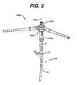
- FIG. 2is a perspective view of another embodiment of the present invention in the form of an assembly tool with a spiral cam and follower mechanism shown in engagement with a prosthesis;
- FIG. 3is a cross section view of FIG. 2 along the line 3 - 3 in the direction of the arrows;
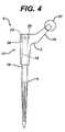
- FIG. 4is a plan view of a two pieced modular hip stem than may be assembled with the assembly tool of FIG. 2 ;
- FIG. 5is an exploded plan view of the modular hip stem of FIG. 4 ;
- FIG. 6is a partial plan view of a proximal body of another embodiment of a two pieced modular hip stem than may be assembled with the assembly tool of FIG. 2 without the counter bore for the assembly nut as in the hip stem of FIG. 5 ;
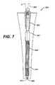
- FIG. 7is a lateral view partially in cross section of the modular hip stem of FIG. 4 ;
- FIG. 8is a plan view of a three piece modular hip stem with a nut that may be assembled with the assembly tool of FIG. 2 ;
- FIG. 9is an exploded plan view of three piece modular hip stem of FIG. 8 ;
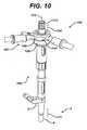
- FIG. 10is a perspective view of the assembly tool of FIG. 2 installed onto the two-piece modular stem of FIG. 4 ;
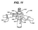
- FIG. 11is a partial perspective view of the assembly tool of FIG. 2 showing the inclined actuating area in greater detail;
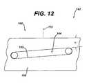
- FIG. 12is a partial unwound view of the inclined actuating area of the assembly tool of FIG. 2 showing the inclined actuating area in greater detail;
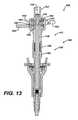
- FIG. 13is a cross-sectional plan view of the assembly tool of FIG. 2 showing the implant of FIG. 8 being disassembled;
- FIG. 14is a partial enlarged plan view of the assembly tool of FIG. 2 showing the ramp actuation mechanism in greater detail;
- FIG. 15is a partial enlarged perspective view of the assembly tool of FIG. 2 showing the ramp actuation mechanism in greater detail;
- FIG. 16is a partial perspective view of the assembly tool of FIG. 2 showing spiral cam portion of the ramp actuation mechanism in greater detail;
- FIG. 17is a partial top view of the assembly tool of FIG. 2 partially disassembled, showing the spool of the ramp actuation mechanism in greater detail;
- FIG. 18is a partial enlarged plan view of the assembly tool of FIG. 2 showing the connector for cooperation with the actuation arm in greater detail;
- FIG. 19is a partial enlarged plan view partially in cross section of the assembly tool of FIG. 2 showing the connector of the actuation arm in greater detail;
- FIG. 20is a plan view partially in cross section of the implant of FIG. 4 showing the implant in engagement with the assembly tool of FIG. 2 ;
- FIG. 21is a plan view partially in cross section of the implant of FIG. 8 showing the implant in engagement with the assembly tool of FIG. 2 ;
- FIG. 22is a partial enlarged view of the implant of FIG. 8 being assembled with the assembly tool of FIG. 2 ;
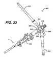
- FIG. 23is a perspective view of the implant of FIG. 4 being disassembled with the assembly tool of FIG. 2 ;
- FIG. 24is a partial enlarged perspective view of the assembly tool of FIG. 2 including the adaptor for use in disassembly;
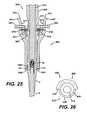
- FIG. 25is a partial cross-sectional plan view of the assembly tool of FIG. 2 showing the implant of FIG. 4 being disassembled and showing the removable disassembly component in position on the assembly tool;
- FIG. 26is a partial top view of the assembly tool of FIG. 2 showing the removable disassembly component in position on the assembly tool;
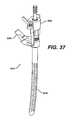
- FIG. 27is a partial enlarged plan view of the implant of FIG. 4 being disassembled with the assembly tool of FIG. 2 ;
- FIG. 28is a partial enlarged plan view of the implant of FIG. 8 being disassembled with the assembly tool of FIG. 2 ;
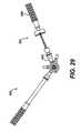
- FIG. 29is a plan view of another embodiment of the present invention in the form of an assembly tool including a torque wrench for measuring the torque applied to the modular implant;
- FIG. 30is a flow chart of a method of using the assembly tool of the present invention according to another embodiment of the present invention.
- FIG. 31is a perspective view of an assembly tool assembly tool with alignment feature according to another embodiment of the present invention.
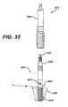
- FIG. 32is an exploded plan view of an articulating reamer and a counterbored reamer for use to prepare a cavity in a long bone for the insertion of an implant that may be assembled with the assembly tool of the present invention
- FIG. 33is a perspective view of a proximal body trial in position on the articulating reamer of FIG. 32 for use with an implant that may be assembled with the assembly tool of the present invention
- FIG. 34is a perspective view of the proximal body trial/articulating reamer assembly of FIG. 33 in cooperation with an alignment tool, the proximal body trial/articulating reamer assembly for use with an implant that may be assembled with the assembly tool of the present invention;
- FIG. 35is a plan view of a proximal body/arcuate distal stem trial assembly for use with an implant that may be assembled with the assembly tool of the present invention
- FIG. 36is a perspective view of the proximal body/arcuate distal stem trial assembly of FIG. 34 in cooperation with the alignment tool of FIG. 34 , proximal body/arcuate distal stem trial assembly for use with an implant that may be assembled with the assembly tool of the present invention;
- FIG. 37is a perspective view of a proximal body trial/arcuate distal stem implant assembly in cooperation with the alignment tool of FIG. 34 , the proximal body trial/arcuate distal stem implant assembly for use with an implant that may be assembled with the assembly tool of the present invention;
- FIG. 38is a plan view of a proximal body implant/arcuate distal stem implant assembly in cooperation with the assembly tool with alignment feature of FIG. 30 ;
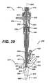
- FIG. 39is a plan view partially in cross section of the assembly tool of FIG. 30 in cooperation with the implant assembly of FIG. 38 ;
- FIG. 40is aside view partially in cross section of the assembly tool of FIG. 30 in cooperation with the implant assembly of FIG. 38 ;
- FIG. 41is a plan view of the assembly tool of FIG. 30 in cooperation with the implant assembly of FIG. 38 ;
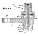
- FIG. 42is a partial plan view in cross section of the assembly tool of FIG. 30 showing the torque input end in greater detail;
- FIG. 43is a cross sectional view of FIG. 42 along the line 43 - 43 in the directions of the arrows;
- FIG. 44is a partial plan view in cross section of FIG. 37 showing a portion of the torque input end in greater detail;
- FIG. 45is a partial plan view in cross section of the assembly tool of FIG. 30 showing the inner force transmitting portion in greater detail;
- FIG. 46is a partial top view of the assembly tool of FIG. 30 showing the proximal body alignment portion in greater detail;
- FIG. 47is a partial end view of the proximal body alignment portion of the assembly tool of FIG. 30 ;
- FIG. 48is a plan view in cross section of the assembly tool of FIG. 30 ;
- FIG. 49is a partial top view of the assembly tool of FIG. 30 showing the distal stem alignment groove and the proximal body alignment indicia in greater detail;
- FIG. 50is a partial plan view in cross section of the assembly tool of FIG. 30 showing the upper portion in greater detail;
- FIG. 50Ais a cross sectional view of FIG. 50 along the line 50 A- 50 A in the directions of the arrows;
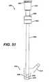
- FIG. 51is a partial plan view of the inner force transmitting portion of FIG. 45 in greater detail
- FIG. 52is a plan view of a unitary reamer for use to prepare a cavity in a long bone for the insertion of an implant that may be assembled with assembly tool of FIG. 37 ;
- FIG. 53is a plan view of a proximal body trial in position on the unitary reamer of FIG. 52 for use with an implant that may be assembled with the assembly tool of FIG. 37 ;
- FIG. 54is a perspective view of the proximal body/unitary reamer assembly of FIG. 53 in cooperation with the alignment tool of FIG. 33 , the proximal body/unitary reamer assembly for use with an implant that may be assembled with the assembly tool of FIG. 37 ;
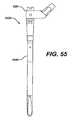
- FIG. 55is a plan view of a proximal body/straight distal stem trial assembly for use with an implant that may be assembled with the assembly tool of FIG. 37 ;
- FIG. 56is a perspective view of the proximal body/straight distal stem trial assembly of FIG. 55 in cooperation with the alignment tool of FIG. 33 , the proximal body/straight distal stem trial assembly for use with an implant that may be assembled with the assembly tool of FIG. 37 ;
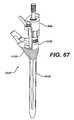
- FIG. 57is a perspective view of a proximal neck trial/straight distal stem implant assembly in cooperation with the alignment tool of FIG. 33 , the proximal body trial/arcuate distal stem implant assembly for use with an implant that may be assembled with the assembly tool of FIG. 37 ;
- FIG. 58is a plan view of a proximal body implant/straight distal stem implant assembly in cooperation with the assembly tool of FIG. 37 ;
- FIG. 59is a plan view of a proximal body trial with a proximal body sleeve in position on the articulating reamer of FIG. 31 for use with an implant that may be assembled with the assembly tool of FIG. 37 ;
- FIG. 60is a perspective view of the proximal neck trial with a proximal body sleeve/articulating reamer assembly of FIG. 59 in cooperation with the alignment tool of FIG. 33 , the proximal body trial with a proximal body sleeve/articulating reamer assembly for use with an implant that may be assembled with the assembly tool of FIG. 37 ;
- FIG. 61is a plan view of a proximal body with a proximal body sleeve/arcuate distal stem trial assembly for use with an implant that may be assembled with the assembly tool of FIG. 37 ;
- FIG. 62is a plan view of the proximal body with a proximal body sleeve/arcuate distal stem trial assembly of FIG. 61 in cooperation with the alignment tool of FIG. 33 , the proximal body with a proximal body sleeve/arcuate distal stem trial assembly for use with an implant that may be assembled with the assembly tool of FIG. 37 ;
- FIG. 63is a perspective view of a proximal body trial with a proximal body sleeve/arcuate distal stem implant assembly in cooperation with the alignment tool of FIG. 33 , the proximal body trial/arcuate distal stem implant assembly for use with an implant that may be assembled with the assembly tool of FIG. 37 ;
- FIG. 64is a plan view of a proximal body implant with a proximal body sleeve/arcuate distal stem implant assembly in cooperation with the assembly tool of FIG. 37 ;
- FIG. 65is a plan view of a proximal body trial with a proximal body sleeve in position on the unitary reamer of FIG. 52 for use with an implant that may be assembled with the assembly tool of FIG. 37 ;
- FIG. 66is a perspective view of the proximal body with a proximal body sleeve/unitary reamer assembly of FIG. 53 in cooperation with the alignment tool of FIG. 33 , the proximal body with a proximal body sleeve/straight reamer assembly for use with an implant that may be assembled with the assembly tool of FIG. 37 ;
- FIG. 67is a plan view of a proximal body with a proximal body sleeve/straight distal stem trial assembly for use with an implant that may be assembled with the assembly tool of FIG. 37 ;
- FIG. 68is a perspective view of the proximal body with a proximal body sleeve/straight distal stem trial assembly of FIG. 55 in cooperation with the alignment tool of FIG. 33 , the proximal body with a proximal body sleeve/straight distal stem trial assembly for use with an implant that may be assembled with the assembly tool of FIG. 37 ;
- FIG. 69is a perspective view of a proximal body trial with a proximal body sleeve/straight distal stem implant assembly in cooperation with the alignment tool of FIG. 33 , the proximal body trial with a proximal body sleeve/arcuate distal stem implant assembly for use with an implant that may be assembled with the assembly tool of FIG. 37 ;
- FIG. 70is a plan view of a proximal body implant with a proximal body sleeve/straight distal stem implant assembly in cooperation with the assembly tool of FIG. 37 ;
- FIG. 71is a flow chart of a method of using the assembly tool of the present invention according to yet another embodiment of the present invention.
- FIG. 72is a flow chart of another method of using the assembly tool of the present invention according to yet another embodiment of the present invention.
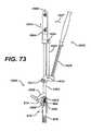
- FIG. 73is a plan view of a proximal body implant/arcuate distal stem implant assembly in cooperation with an assembly tool according to yet another embodiment of the present invention showing an assembly tool with a lever mechanism;
- FIG. 73Ais a partial plan view partially in cross section of FIG. 73 showing the actuation members in greater detail;
- FIG. 73Bis a top view of FIG. 73 showing an alignment feature in greater detail
- FIG. 73Cis a partial plan view partially in cross section of FIG. 73 showing the attachment to the distal stem of the prosthesis in greater detail;
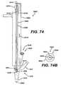
- FIG. 74is a plan view of a proximal body implant/arcuate distal stem implant assembly in cooperation with an assembly tool according to yet another embodiment of the present invention showing an assembly tool internally and externally threaded components;
- FIG. 74Ais a partial plan view partially in cross section of FIG. 74 showing the cooperation of the actuation members in greater detail;
- FIG. 74Bis a top view of FIG. 74 showing an alignment feature in greater detail
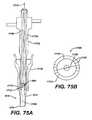
- FIG. 75is a plan view of a proximal body implant/arcuate distal stem implant assembly in cooperation with an assembly tool according to yet another embodiment of the present invention showing an assembly tool with a spiral engagement mechanism;
- FIG. 75Ais a partial plan view partially in cross section of FIG. 75 showing the actuation members in greater detail.
- FIG. 75Bis a top view of FIG. 75 showing an alignment feature in greater detail.
- the assembly tool 1is used for assembly of a first component 2 of a prosthesis 4 to a second component 6 of the prosthesis 4 for use in joint arthroplasty.
- the tool 1includes a first member 8 operably associated with the second component 6 .
- the first member 8defines a first member longitudinal axis 10 of the first member 8 .
- the tool 1also includes a second member 12 operably associated with the second component 6 .
- the second member 12defines a second member longitudinal axis 14 of the second member 12 .
- the second member 12is adapted to provide relative motion of the second member 12 with respect to the first member 8 when the second member 12 is rotated relative to the first member 8 about the second member longitudinal axis 14 .
- the assembly tool 1is suited for use with the prosthesis 4 when, for example, the prosthesis 4 includes the first component 2 and the second component 6 which are engaged and disengaged by relative motions along an axis.
- the assembly tool 1is suitable when the prosthesis 4 includes components, which are connected by a tapered connection.
- the first component 2includes an internal taper 16 that mates with an external taper 18 located on the second component 6 .
- the first component 2is engaged with the second component 6 when the first component 2 moves in the direction of arrow 20 and/or when the second component 6 moves in the direction of arrow 22 .
- the first member 8is operably associated with the first component 2 while the second member 12 is operably associated with the second component 6 .
- the first member 8includes a first member operating feature 24 which is operably associated with a first component operating feature 26 of the first component 2 .
- the second memberincludes a second member operating feature 28 which cooperates with a second component operating feature 30 of the second component 6 .
- the first member 8 and the first component 2are merely required to prevent motion of the two components toward each other, the first member 8 and the first component 2 may be designed such that the first member operating feature 24 may be in the form of a bottom and/or surface. Similarly, the first component operating feature 26 may be in the form of a top surface of the first component 2 .
- the second member operating feature 28 and the second component operating feature 30may be any features capable of urging the second component 6 upwardly in the direction of arrow 22 .
- the second member operating feature 28may be in the form of internal threads formed on the second component operating feature 26 , which may mate with external threads 30 formed on the second component 6 .
- the first member 8 and the second member 12may have any shape or configuration capable of providing relative motion along first member longitudinal axis 10 and second member longitudinal axis 14 .
- the first member 8may be in the form of a hollow component or tube.
- the second member 12may be in the form of a rod or cylinder, which may slidably fit within the first member 8 .
- the first member 8may include a longitudinal opening 32 .
- the second member 12In order to move the second component 6 into engagement with the first component 2 , it should be appreciated that the second member 12 must move in the direction of arrow 34 with respect to the first member 8 .
- the second member 12may include a rod portion 36 having a cylindrical periphery 38 thereof.
- the first member 8may, as shown in FIG. 1 , include a cylindrical tubular portion 40 that defines the opening 32 therein.
- the rod periphery 38 of the second member 12defines an outside diameter OD which is matingly fitted with dimension ID of the opening 32 of the tubular portion 40 .
- the relative motion of the first member 8 with respect to the second member 12may be controlled by, for example, a relative motion feature 42 .
- the relative motion feature 42may be in the form of a threaded connection.
- the threaded connection 42may, for example, as shown in FIG. 1 , include a first member relative motion feature 44 in the form, of for, example internal threads.
- the internal threads 44are formed on internal periphery 46 of the tubular portion 40 of the first member 8 .
- the relative motion feature 42may also include a second member relative motion feature 48 .
- Second member relative motion feature 48may be in the form of, for example, external threads formed on rod portion 36 of the second member 12 .
- the threads 44 and 48cooperate to provide the relative motion of the second member 12 in the direction of arrow 34 with respect to the first member 8 .
- the threads 44 and 48are matingly engaged and have a pitch selected to provide for the desired mechanical advantage.
- the amount of relative motion of the first member 8 with respect to the second member 12is limited.
- Such a limited relative motion of the first member 8 with respect to the second member 12correspondingly limits the motion of the first component with respect to the second component 6 thus preventing over-tightening of the prosthesis 4 .
- the motion of the first member 8 with respect to the second member 12may be accomplished in any suitable fashion.
- the external threads 48may have a thread length LE which is slightly greater than the thread length LI of the internal threads 44 of the first member 8 .
- the motion in the direction of arrows 34 and 38 of the component 12 with respect to component 8is limited by the difference of the thread lengths LE and LI.
- the threads 44 and 46may only limit the motion of the members 8 and 12 if the major diameters of the threads 44 and 48 provide interference with the first member 8 or the second member 12 . It should be appreciated that stops (not shown) may be utilized to limit the relative motion of the first member 8 with respect to the second member 12 .
- a cap 52 and a collar 54both secured to first meter 8 and both shown in phantom, may be utilized to limit the relative motion of the first member 8 with respect to the second member 12 .
- the second member 12in order to move the second member 12 in the direction of arrow 34 with respect to the first member 8 , the second member 12 must be rotated in the direction of arrow 56 with respect to first member 8 . This motion assembles the components 2 and 6 .
- the second member 12in order for the second member 12 to move in the direction of arrow 39 with respect to the first member 8 , the second member 12 must be rotated in the direction of arrow 60 with respect to the first member 8 . This motion disassembles the components 2 and 6 .
- the second member 12may include a second member handle 62 extending outwardly from the rod portion 36 of the second member 12 .
- the first member 8may similarly include a first member handle 64 extending outwardly from the tubular portion 40 of the first member 8 .
- the handles 62 and 64may have any suitable size and shape capable of receiving for example the hands of the surgeon or operator of the assembly tool 1 .
- the assembly tool 1may likewise be utilized to disassemble the first component 2 from the second component 6 . It should be appreciated that the assembly tool 1 may be adapted for use for the disassembly of the first component 2 from the second component 6 . It should be appreciated that one of the first member 8 and the second member 12 may be associated with one of the first component 2 and the second component 6 such that as the first member 8 is moved relative to the second member 12 , the first component 2 may be disassembled from the second component 6 . To accomplish this, one of the first member 8 and the second member 12 is operably associated with the first component 2 while the other of the first member 8 and the second member 12 is operably associated with the second component 6 .
- the second member 12may be operably associated with the second component 6 by, for example, utilizing the second member cooperating feature 28 in the form of internal threads to cooperate with the second component operating feature 30 in the form of external threads.
- the first member 8is similarly operably associated with the first component 2 .
- the first component 2In order that the second component 6 may be forced to move in the direction of arrow 63 while the first component 2 is required to move in the direction of arrow 65 , the first component 2 must be restrained by the first member 8 .
- the first component 2is held against the first member 8 by, for example, a third member 66 .
- the third member 66cooperates with the first member 8 and the first component 2 to hold the two components against each other.
- the third member 66may cooperate with the first member 8 and the first component 2 in any suitable fashion.
- the first member 8may include a first member disassembly operating feature 68 which cooperates with the third member 66 .
- the first component 2may include a first component disassembly operating feature 70 which cooperates with the third member 66 .
- the third member 66may have any suitable design or shape and may, for example, be in the form of first fork 72 and second fork 74 .
- the forks 72 and 74may be urged together by, for example, springs 76 .
- the first fork 72may include a first tine 78 which engages with the first member disassembly operating feature 68 in the form of, for example, a first member groove.
- the first fork 72may include a second tine 80 for cooperation with the first component operating disassembly feature 70 in the form of, for example, a second component groove.
- the second fork 74may include a first tine 82 for cooperation with the first member groove 68 as well as a second tine 84 for engagement with the second groove 70 .
- the third member 66is not used.
- the assembly tool 1is positioned with respect to the prosthesis 4 such that the internal threads 28 of the second member 12 engage the external threads 30 of the second component 6 .
- the internal threads 28 and the external threads 30are threaded into engagement with each other and the second member 12 is rotated with respect to the second component 6 until the bottom end surface 24 of the first member 8 is in contact with the top surface 26 of the first component 2 .
- the second member handle 62is rotated in the direction of arrow 56 until the second member handle has come to the stop created by the relative motion feature 42 .
- the third member 66When utilizing the assembly tool 1 to disassemble the first component 2 from the second component 6 the third member 66 is utilized and placed in position on the assembly tool 1 .
- the forks 72 and 74 of the third member 66are placed in position in the first member grooves 68 and the first component grooves 70 .
- the top surface 26 of the first component 2is thus in contact with the bottom end surface 24 of the first member 8 .
- the second component 6is then threadably engaged into the second member 12 .
- the second member handle 62is then rotated in the direction of arrow 60 until the relative motion feature 42 ends the movement of the second member handle 62 thereby disassembling the first component 2 from the second component 6 .
- the assembly tool 100is utilized for assembling the first component 2 of the prosthesis 4 to the second component 6 of the prosthesis 4 .
- the prosthesis 4may be used, for example, in joint arthroplasty.
- the tool 100is similar to the tool 1 of FIG. 1 and includes a first member 108 operably associated with the first component 2 .
- the first member 108defines a first member longitudinal axis 110 thereof.
- the assembly tool 100further includes a second member 112 which is operably associated with the second component 6 .
- the second member 112defines a second member longitudinal axis 114 thereof.
- the second member 112is similar to second member 2 of the assembly tool 1 of FIG. 1 .
- the second member 112is adapted to provide relative motion of the second member 112 with respect to the first member 108 when the second member 112 is rotated relative to the first member 108 about the second member longitudinal axis 114 .
- the assembly tool 100may be configured such that the relative motion of the second member 112 with respect to the first member 108 corresponds to the relative motion of the first component 2 with respect to the second component 6 to urge the second component 6 into engagement with the first component 2 .
- the second component 6includes a second component operating feature in the form of external threads 30 .
- the external threads 30are matingly fitted to, for example, internal threads 128 formed on second member 112 .
- the first component 2includes an operating feature in the form of, for example, a top surface 26 which mates with bottom surface 124 of the first member 108 of the tool 100 .
- the second member 112Since the first member 108 is in contact with the first component 2 as the first component moves in the direction of arrow 122 relative to the first component 2 , the second member 112 , which threadably secured to the second component 6 moves in the direction of arrow 134 relative to the first member 108 .
- the relative motion of the second member 112 with respect to the first member 108 in the direction of arrow 134corresponds to the relative motion of the second component 6 with respect to the first component 2 in the direction of arrow 122 .
- the prosthesis 4 as shown in FIG. 4includes a taper connection 17 .
- the taper connectionconsists of the external taper 18 formed on the distal stem 6 that engages with internal taper 16 formed on the first component in the form of the proximal body 2 .
- the prosthesis for use with the assembly tool 1 or 100 of FIGS. 1 and 2may include a proximal body 2 and a distal stem 6 which have an interference connection that is, for example, a interference connection of a cylindrical bore to a cylindrical stem, as well as, a splined non-uniform cross-section stem to a splined or non-uniform cross-section opening.
- proximal body and distal stem of the prosthesis 4 for use with the assembly tool of the present inventionmay include a taper connection in which the distal stem has an internal taper and the proximal body has an external taper.
- the prosthesis 4 as shownmay include external threads 30 formed on the distal stem 6 .
- the proximal body 2may include a neck 19 to which a head 21 may matingly be fitted.
- the prosthesis 4may further include a nut 23 which threadably engages the external threads 30 of the distal stem 6 .
- the prosthesis 4is shown with the proximal body 2 disassembled from the distal stem 6 .
- the external taper 18 of the distal stem 6is defined by an included angle ⁇ 1 .
- the proximal body 2includes the internal taper 16 defined by included angle ⁇ 2 .
- the angles ⁇ 1 and ⁇ 2may be generally the same. Alternatively the taper angle may be divergent.
- the angles ⁇ 1 and ⁇ 2should be chosen, such that the fit of the proximal body 2 to the distal stem 6 is secure.
- Prosthesis 204includes a proximal body 202 which does not include a counterbore.
- Prosthesis 204may include a nut 223 which mates with outer face 226 that is not recessed. The nut 223 threadably engages distal stem 206 .
- the prosthesis 304includes a proximal body 302 similar to the proximal body 2 of the prosthesis 4 of FIG. 4 .
- the prosthesis 304also includes a distal stem 306 that is different than the distal stem 6 of the prosthesis 4 of FIG. 4 .
- the distal stem 306is bent and has a proximal portion 307 having a longitudinal centerline 309 and a distal portion having a longitudinal centerline 313 .
- the centerlines 309 and 313form angle ⁇ therebetween.
- the distal stem 306may further include an elongated slot 329 extending axially from the end of the stem 306 .
- Prosthesis 404is similar to the prosthesis 304 of FIG. 7 .
- Prosthesis 404includes a proximal body 402 which is connected to a distal stem 406 .
- the proximal body 402includes a neck 419 to which a head 421 may be positioned.
- the prosthesis 404may further include a nut 423 to assist in connecting the proximal body 402 to the distal stem 406 .
- the prosthesis 404may further include an external sleeve 427 which is fitted to the proximal body 402 by means of an internal taper 429 which mates with an external taper 431 on the proximal body 402 .
- the stem 406may be bent in a continuous arc.
- the assembly tool 100is shown in position on the prosthesis 4 .
- the first member 108is in contact with the first component 2 and the second member 112 is threadably engaged to the second component 6 .
- the assembly tool 100is utilized to move the second component 6 in the direction of arrow 111 with respect to the first component 2 . This relative motion is accomplished by moving the second member 112 in the direction of arrow 134 in relation to the first member 108 .
- the relative motion of the first member 108 with respect to the second member 112may be accomplished by, for example, a relative motion feature 142 .
- the relative motion feature 142may include a first member relative location feature 144 in the form of slot 144 within which a second member relative motion feature 148 in the form of, for example, a pin is rollably restrained with the slot 144 .
- the relative motion feature 142is utilized to move the second member 112 about the second member longitudinal axis 114 with respect to the first member 108 .
- the slot 144extends from first centerline 151 to second centerline 153 .
- the centerlines 151 and 153represent the arcuate end portions of the slot 144 defined with a radius R′ equal to the slot width SW divided by two.
- the slot 144is defined by a first assembly load surface 155 and an opposed second disassembly load surface 157 .
- the load surfaces 155 and 157are parallel to each other and spaced apart a distance equal to SW or the slot width SW.
- a slot length angle ⁇defines the arcuate difference from first member centerline 110 along slot radius R of the first member 108 between the first centerline 151 and the second centerline 153 .
- the angle ⁇preferably selected to provide for the proper displacement of the assembly tool 100 .
- the proper displacement of the assembly tool 100may be predetermined by calculating the desired locking force on the joint of the prosthesis 2 .
- the assembly load surface 155is inclined relative to a surface perpendicular to the longitudinal axis 110 of the first member 108 at a ramp angle of ⁇ .
- the angle ⁇ , as well as, the radius R (see FIG. 16 )affect the displacement of the assembly tool 100 .
- Rthe slot 144 radius from centerline 110 in inches
- ⁇the ramp angle in degrees.
- the assembly tool 100may include a second pin 149 opposed to the first pin 148 which matingly fits within a second slot 145 opposed to the first slot 144 .
- First and second pins 148 and 149are preferably diametrically opposed and the first slot 144 and the second slot 145 are likewise preferably diametrically opposed.
- the second pin 149 and the second slot 145serve to balance the forces and loads upon the assembly tool 100 .
- the assembly tool 100may include an actuating arm 162 similar to arm 62 of tool 1 of FIG. 1 and a restraining arm 164 similar to arm 64 of tool 1 of FIG. 1 .
- the actuating arm 162 and the restraining arm 164may be, for example, modular.
- the arm 162may include an arm connecting base 159 and an arm extension 161 removably connectable to the arm connecting base 159 .
- the arm connecting base 159includes a base 163 including a bayonet-type groove 165 .
- a stem 167may extend from the base 163 .
- the arm extension 161may include a pair of pins 169 extending toward the opening 171 in the arm extension 161 .
- the opening 171receives the base 163 and the stem 167 of the arm connecting base 159 (see FIG. 18 ).
- the pins 148 and 149are shown in greater detail.
- the pins 148 and 149are preferably rotatably mounted on pin stems 173 .
- the pin stems 173may be threadably connected to the second member 112 . It should be appreciated that the pins 148 and 149 may be mounted to the pin stems 173 by means of needle bearings (not shown).
- the prosthesis 4is shown in engagement with the assembly tool 100 .
- Surface 124 of the first member 108 of the assembly tool 100is placed against top face 26 of the proximal body 2 of the prosthesis 4 .
- the internal threads 128 of the second member 112 of the assembly tool 100is threadably engaged with external threads 30 of the stem 6 of the prosthesis 4 .
- nut 23 shown in phantomis secured to the external threads of the stem 6 .
- the prosthesis 404is shown in connection with the assembly tool 100 .
- Outer surface 124 of the first member 108 of the assembly tool 100is placed against top surface 426 of the proximal body 402 of the prosthesis 404 .
- the internal threads 128 of the second member 108 of the assembly tool 100is threadably engaged with external threads 430 of the distal stem 406 .
- nut 423 shown in phantomis positioned on the external threads 430 of the distal stem 406 .
- first member 108 and the second member 112may be made of a one-piece or unitary construction, it should be appreciated that the first member 108 and the second member 112 may be made of multiple components or may be modular.
- the first member 108may include a sleeve portion 140 , having a lower sleeve 186 as well as an upper sleeve 188 .
- the lower sleeve 186may be connected to the upper sleeve 188 in any suitable manner, for example, by welding, by press fit, or as shown in FIG. 13 , by being threadably connected.
- the first member 108may also include a third component in the form of the first member handle 164 .
- the first member handle 164may be removably connected to the upper sleeve 188 by, for example, a bayonet connection such as that described in FIGS. 18 and 19 herein.
- the second member 112may be made of a modular or multi-piece construction.
- the second member 112may include a rod portion 136 removably connected to a cap 152 .
- the rod portion 136may be secured to the cap 152 in any suitable fashion.
- the cap 152may be welded to the rod portion 136 , or be press fitted thereto.
- the rod portion 136may be threadably connected to the cap 152 by means of a screw 190 threadably secured to the rod portion 136 and trapping the cap 152 therebetween.
- the cap 152 and the rod portion 136cooperate to form a spool 192 therebetween.
- the spool 192includes a first retaining portion 194 extending from the rod portion 136 and a spaced-apart and parallel second restraining portion 196 .
- a central portion 198is positioned between the first restraining portion 194 and the second restraining portion 196 .
- the second member 112 of the assembly tool 100further includes a ring 185 rotatably positioned about the central portion 198 of the rod portion 136 .
- the pin 148is retainably connected to the ring 185 .
- the handle 162is fixedly secured to the ring 185 by, for example, a press fit or fitted connection similar to the connection of FIGS. 18 and 19 .
- assembly tool 500is shown for use in disassembling the prosthesis 4 .
- the assembly tool 500is similar to the assembly tool 100 and in fact includes all the components of the assembly tool 100 plus a third member 566 for use in disassembling the prosthesis 4 .
- the assembly tool 500thus includes a first member 508 identical to the first member 108 as well as a second member 512 identical to the second member 112 of the assembly tool 100 (see FIG. 13 ).
- the assembly tool 500includes an actuating arm 562 identical to the actuating arm 162 of the tool assembly 100 .
- the assembly tool 500further includes a restraining arm 561 identical to the restraining arm 162 of assembly tool 100 , except that the arm extension 161 of the restraining arm 162 is moved from first arm stem 564 to second arm stem 563 .
- the assembly tool 500includes a slot 544 identical to the slot 144 of the assembly tool 100 .
- Pin 548identical to pin 148 of the assembly tool 100 , slidably fits within the slot 548 .
- the third member 566includes a collar 576 which is slidably fitted over the first member shoulder 568 .
- First arm 572 and second arm 574are pivotally mounted to the collar 576 by pivot pins 579 .
- the arms 572 and 574are urged in the direction of arrows 577 by springs 578 positioned between the arms 572 and 574 and the collar 576 .
- Screws 582are threadably secured to the arms 572 and 574 to limit the movement of the upper portion of the arms 572 and 574 toward the first member 508 .
- First location pin 580 and second location pin 584are positioned on the first arm 572 and the second arm 574 , respectively, for engagement with holes 70 in the proximal body 2 of the prosthesis 4 .
- the location pins 580 and 582are engaged in the holes 70 of the proximal body 2 of the prosthesis 4 .
- Internal threads 528 of the second member 508are then threadably engaged into the external threads 30 of the distal stem 6 of the prosthesis 4 .
- the second member 512is then continually tightened until the second member 512 is finger tight to the distal stem 6 .
- the pins 580 and 584are moved from the proximal body 2 by first moving the arms 572 and 574 in the direction of arrows 581 by means of the operator's fingers. When in position the arms 572 and 574 are released so that the pins 580 and 584 may be properly engaged in the holes 70 of the proximal body 2 of the prosthesis 4 .
- the collar 576 of the third member 566is shown in position on the first member 508 .
- the third member 566is assembled to the first member 508 by moving the third member 566 in the direction of arrow 575 .
- the assembly tool 500is shown for use with the prosthesis 4 to disassemble the proximal body 2 from the distal stem 6 .
- the pins 580 and 584 of the arms 572 and 574 of the third member 566are engaged in holes 70 of the proximal body 2 of the prosthesis 4 .
- the internal threads 528 of the second member 512are threadably engaged with the external threads 30 of the distal stem 6 .
- the second member 512is then moved downwardly in the direction of arrow 583 , thereby separating the distal stem 6 from the proximal body 2 .
- the assembly tool 500is shown in engagement with the prosthesis 404 to remove the distal stem 406 of the prosthesis 404 from the proximal body 402 .
- the pins 580 and 584 of the arms 572 and 574 of the third member 566are engaged in holes 470 of the proximal body 402 of the prosthesis 404 .
- the internal threads 528 of the second member 512are threadably engaged with the external threads 430 of the distal stem 406 of the prosthesis 404 .
- the second member 512is then moved in the direction of arrow 583 with respect to the proximal body 402 of the prosthesis 404 thereby separating the distal stem 406 from the proximal body 402 of the stem 404 .
- Assembly tool 600is similar to assembly tool 100 or assembly tool 500 of FIG. 2 and FIG. 24 , respectively, except that articulating arm 662 of the assembly tool 600 is different than the articulating arm 562 of the assembly tool 500 in that the articulating arm 662 includes a torque wrench 689 extending from the arm stem 663 .
- the torque wrench 689serves to provide a reading of the torque applied by the assembly tool 600 .
- the torque wrench 689may be of a type for recording or reading the applied torque or may be a torque wrench which has a break away or clicking torque at a particular value.
- Such a torque limiting wrenchmay provide for an accurate torque to be applied by the assembly tool 600 .
- a thrust washer or other force transducermay be positioned in the first member or the second member to monitor the force asserted by the assembly tool.
- Kit 700includes the assembly tool 100 as well as the prosthesis 4 .
- the assembly tool 100 and the prosthesis 4form a kit.
- the kitmay be provided with the prosthesis 4 assembled or with the prosthesis 4 disassembled including both the proximal body 2 and the distal stem 6 .
- Assembly tools 1 , 100 and 500 as shown in FIGS. 1 , 2 and 24 respectively,may be made of any suitable material and may, for example, be made of a metal. If made of metal, preferably the assembly tool is made of a sterilizable material.
- the assembly tools 100 and 500may be made of components of, for example, cobalt chromium alloy, stainless steel alloy, or a titanium alloy. Articulating surfaces of the assembly tool may be surface hardened by processes such as flame hardening.
- the method 800includes a first step 802 of providing a prosthesis including a first component and a second component removably attached to the first component.
- the surgical procedure 800also includes a second step 804 of providing an instrument having a first member and a second member rotatably movable with respect to the first member in a plane perpendicular with the first member, the first member cooperable with the second component and the second member cooperable with the second component.
- the method 800may further include a third step 806 of assembling the first component to the second component and a fourth step 808 of connecting the first member of the tool to the first component.
- the method 800may further include a fifth step 810 of connecting the second member of the tool to the second component and a sixth step 812 of rotating the first member of the tool with respect to the second member of the tool to secure the second component to the first component.
- assembly tool 900is shown for assembly of a first component 814 of a prosthesis 816 to the second component 818 of the prosthesis 816
- the prosthesis 816is for use in joint arthoplasty.
- the tool 900includes a first member 902 operably associated with the first component 814 and a second member 904 operably associated with the second component 818 .
- the first member 902 and the second member 904are adapted to provide for the assembly of first component 814 of the prosthesis 816 to the second component 818 of the prosthesis 816 .
- the second member 904is operably associated to the second member 902 to provide relative motion between the first member 902 and the second member 904 for assembly of the first component 814 to the second component 818 .
- the assembly tool 900further includes an angular orientor 906 , that cooperates with the first member 902 or the second member 904 for either replicating or measuring the relative angular orientation of the first component 814 with respect to the second component 818 .
- articulating reamer 820is shown for preparing a cavity 822 in a long bone 824 .
- the cavity 822provides for a position in the long bone 824 for the insertion of, for example, prosthesis 816 of FIG. 31 .
- Articulating reamer 820is particularly well suited for use in revision surgeries. In revision surgeries, the distal stem is placed more distally than a primary prosthesis so that the distal stem may engage undisturbed bone that has not previously supported a prosthesis.
- the long bone 824in particularly the femur for use in supporting the distal stem of a hip prosthesis is typically curved or arcuate.
- the long bone 824thus may have an arch or radius of curvature R defined by for example, a radius of curvature R.
- the position of the arch or curvature of long bone 824is a reasonable indicator of the anatomy of the patient.
- the position of the curvature of the long bone 824may be a relative indicator of the proper position of, for example the natural femoral head with respect of the position of the curvature of a long bone 824 .
- the position of the curvature of the long bone 824may thus provide an indication of the proper alignment of the first component 814 to the second component 818 of the prosthesis 816 of FIG. 31 .
- articulating reamer 820includes a distal portion 826 , that articulates with respect to the first or shaft portion 828 of the reamer 820 about pivot point 830 .
- a counterbore reamer 832may slideably fit over shaft portion 828 of the articulating reamer 820 for reaming the proximal portion of the long bone 824 for receiving the prosthesis 816 .
- the articulating reamer 820may include a connector 834 positioned on the proximal portion 828 of the articulating reamer 820 .
- the articulating reamer 820 and the counterbore reamer 832combine to form reamer assembly 812 and are well suited for use of long bones 824 , which are arcuate.
- a more complete description of use of articulating and counterbore reamers and their use with orthopaedic trials and implants for hip revision surgeriescan be more understood by reference to U.S. patent application Ser. No. 10/606,304 filed Jun. 25, 2003 entitled “NON-LINEAR REAMER FOR BONE PREPARATION AND ASSOCIATED METHOD” incorporated in its entirety by reference.
- a modular body trial 836is shown in position on the articulating reamer 820 .
- the modular body trial 836 and the articulating reamer 820may be used in revision hip arthoplasty with the prosthesis 816 and the alignment tool 900 of the present invention as shown in FIG. 31 .
- articulating reamer 820remains in the medullary canal of the long bone 824 after the reaming operation has been complete.
- the proximal body trial 836is thus assembled into the articulating reamer 820 while the reamer 820 is still in the canal of the long bone to form trial reamer assembly 837 .
- Thispermits the trialing of the prosthesis without the use of a modular trial and avoids the inaccuracy as well as the time involved in such an additional step of removing the articulating reamer and inserting the distal end of the proximal body trial.
- the proximal body trial 836may be rotated in the direction of arrows 838 along longitudinal axis 840 to properly position proximal trial body 836 in the patient.
- nut 842may be loosened and the proximal body trial 836 may be rotated in the direction of arrows 838 with teeth 834 being used to control by finite angular movements of, the trial 836 .
- teeth 834being used to control by finite angular movements of, the trial 836 .
- each toothrepresents 15 degrees of movement.
- an alignment tool 846may be utilized to measure the preferred anglar orientation of the proximal body trial 836 to the articulating reamer 820 .
- the alignment tool 846is shown in greater detail in U.S. patent application Ser. No. 10/327,196 entitled “ALIGNMENT DEVICE FOR MODULAR IMPLANTS AND METHODS” incorporated here in its entirety by reference.
- the proximal body trial 836is shown assembled with an arcuate distal trial assembly 848 to form the trial assembly 850 .
- the assembly 850may be utilized instead of the body trial articulating reamer assembly 837 of FIG. 33 .
- the trial assembly 850may be used in addition to the proximal body trial articulating reamer assembly 837 as an additional step to verify the appropriateness of the trial and corresponding prosthesis for the patient.
- the assembly 850is shown with the alignment tool 846 in position on the proximal body trial 836 .
- the alignment tool 846may be utilized to properly orient the proper body trial with respect to arcuate distal stem trial 848 or be used to record the relative position of the proximal body trial 836 to the arcuate distal stem trial 848 .
- Trial implant assembly 852includes proximal body trial 836 as well as acruate distal stem implant or second component 818 .
- the alignment tool 846is used to angularly orient proximal body trial 836 to acruate distal stem 818 in a position similar to that of the trial assembly 850 or the proximal body trial acruate reamer assembly 837 (see FIGS. 36 and 33 , respectively).
- the acruate distal stem trial 848 or the articulating reamer 820may be removed from the canal of the long bone and the arcuate distal stem implant 818 inserted in the long bone.
- the proximal body trial 836is positioned with respect to the acruate distal stem implant 818 by use of the alignment tool 846 utilizing in the measurements or settings obtained from trial assembly 850 or the reamer trial assembly 837 .
- the assembly tool with alignment feature 900 of the present inventionis shown in position on implant assembly or prosthesis 816 .
- Alignment informationmay be obtained from alignment tool 846 positioned on trial implant assembly 852 of FIG. 37 , from trial assembly 850 of FIG. 33 or from the proximal trial body articulating reamer assembly 837 of FIG. 33 .
- the alignment informationmay be used to determine the proper anglar orientation of the arcuate distal stem implant with respect to the proximal body implant 814 to provide for a properly assembled implant assembly 816 .
- the assembly tool 900may, as shown in FIG. 39 , be configured such that the first member 902 defines first member longitudinal 908 .
- the second member 904may define a second member longitudinal axis 910 .
- the second member 904may be adapted to provide relative motion of the second member 904 with respect to the first member 902 when the second member 904 is rotated relative to the first member 902 about the second member longitudinal axis 910 .
- the relative motion of the second member 904 with respect to the first member 902may be utilized to affect the relative motion of the proximal body 814 or the first component with respect to the distal stem or second component 818 to urge the distal stem 818 into engagement with the proximal body 814 .
- the assembly tool 900may be adapted as shown in FIG. 39 to provide for the first member 902 including a first member relative motion feature 914 .
- the first member relative motion featuremay be in the form of threads 914 formed on first member 902 .
- the second member 904may include a second member relative motion feature 916 .
- the second member relative motion feature 916may be in the form of, for example, threads formed on second member 904 .
- the first member relative motion feature 914 and the second member relative motion feature 916cooperate with each other to provide the relative motion of the first member 902 with respect to the second member 904 .
- the first member relative motion feature 914 or the second member relative motion feature 916may include, as discussed above, threads.
- the first member 902may include a body 918 defining a generally cylindrical opening 920 in the body 918 .
- the second member 904 of assembly tool 900may further include a portion 922 of the second member 904 , which is matingly fitted to transverse within the cylindrical longitudinal opening 920 of the first member 902 .
- the portion 922may be in the form of, for example, a translating member.
- the assembly tool 900may further include a cooperating member 924 for cooperating with the second component or distal stem 818 .
- the cooperating member 924cooperates with the angular orientation feature 906 to replicate and/or measure the angular orientation of the first component 814 with respect to the second component or distal stem 818 .
- the cooperating member 924may have any suitable size and shape and may for example, be in the form of a cylindrical rod extending longitudinally through assembly tool 900 .
- the cooperating member 924may include the second member relative motion feature or tang 912 .
- the assembly tool 900may be configured such that the first component or proximal body 814 of the implant assembly 816 includes an internal taper 854 .
- the distal stem or second component 818 of the implant assembly 816may include an external taper 856 .
- the second component 818may further an external thread 858 extending from the external taper 856 .
- the second member 904may include an internal thread 926 for making an engagement with external threads 858 of the second component 818 .
- the assembly tool 900may be configured such as the first member longitudinal axis 908 and the second member longitudinal axis 910 are coincident.
- the angular orientation feature 906 of the assembly tool 900may have any suitable size, shape, and configuration
- the angular orientation feature 906may for example, include first orientor 928 connected to the first member 902 .
- the first orientor 928cooperates with the first component or proximal body 814 of the implant assembly 816 .
- the first component 814includes a first timing feature 860 .
- the first orientor 928is operably associated with the first timing feature 860 .
- the first orientormay include a pair of pins 930 , which mate with openings 862 located on the first component 814 .
- the angular orientation feature 906may further include a second orientor in the form of, for example tang 912 .
- the tang 912is operably associated with the second member 904 for cooperation with the distal stem or second component 818 of the implant assembly 816 .
- the second component 818includes a second timing feature 864 in the form of, for example, a slot.
- the second orientor or tang 912is operably associated with the second timing feature 864 , for example, the slot.
- the assembly tool 900may further include a device for preventing or controlling over-tightening or securing of the first component 814 to the second component 818 of the implant assembly 816 .
- the assembly tool 900may include a displacement measuring device 930 or a force measuring device 932 , or both.
- the displacement measuring device 930may be utilized for measuring the displacement of the first component 814 relative to the second component 818 .
- the force measuring device 932may be utilized for the measuring of the force related to the relative motion of the first component 814 with respect to the second component 818 .
- the displacement measuring device 930may be for example, in the form of indicia 930 including a first mark 934 on for example, first member 902 and a second mark 936 moveable with, for example, second component 818 .
- the distance between the first mark 934 and the second mark 936may be representative of the displacement of the first component 814 with respect to the second component 818 .
- Force measuring device 932may be in the form of, for example thrust washer 932 . It should be appreciated that additional force measuring devices in the form of for example, a strain gage or similar devices may be utilized. Alternatively, the force measuring device 932 may be in the form of, for example, torque wrench 938 .
- the torque wrench 938may be a hand or power tool.
- the torque wrench 938may include a feature (not shown) to limit torque such as a clutch or power tool control.
- the assembly tool 900may be configured such that the first member 902 and or the second 904 include a handle 942 extending outwardly from the first member 902 or the second member 904 .
- the handle 942extends outwardly from handle stem 940 , which extends outwardly from first member 902 of the assembly tool 900 .
- the handle 942is utilized to assist in holding and stabilizing the assembly tool 900 and to provide resistance to the assembly tool 900 as it is utilized to remove or join the implant assembly 816 .
- the assembly tool 900may be configured such that the first member 902 defines a central cavity 920 in the first member 902 . Further the assembly tool 900 may be configured such that first member 902 also includes a translating member or translating portion 922 cooperable with the first member 902 .
- the translating member 922may be fitted at least partially in the central cavity or opening 920 .
- the translating member 922may define a translating member longitudinal axis 944 .
- the translating member 922may be adapted as shown in FIG. 42 , to translate along the translating member longitudinal axis 944 when the second member 904 is rotated.
- first orientor 928 of the angular orientation feature 906is shown in greater detail. While the first orientor 928 may have any suitable shape or configuration capable of orienting first component 814 , the first orientor 928 for example, may include a pair of spaced apart arms 946 , which rotate about pivot pins 948 . Engagement pins 930 are matingly fitted into the openings 862 formed in the proximal body 814 of the implant assembly 816 . The first orientor 928 , as shown in FIG. 47 , is thus pivotally connected to the first member 902 . The pins 948 , shown in FIG. 47 , are connected to first orientor body 950 .
- the body 950 of the first orientor 928is slideably fitted to body 918 of the assembly tool 900 .
- the ability of the first orientor 928 to slideably and pivotally be movable to respect to the assembly tool 900permits the pins 930 to engage the proximal body 814 of the implant 816 in many different positions permitting a variety of proximal body configurations to be compatible with assembly tool 900 .
- first member 902 and the second member 904may each have an integral or one-piece construction, it should be appreciated the first member 902 and the second member 904 may be made of two or more components.
- the assembly tool 900may include a modular first member 902 and a modular or multi-piece second member 904 .
- the first member 902may include the body 918 .
- Body cap 952may be for example, threadably secured to proximal end 954 of the body 918 of the first member 902 .
- a turnbuckle 956is threadably secured to the body 918 and an orientation sleeve 958 is threadably secured to the turn buckle 956 .
- the orientor housing 950slideably fits over the orientation sleeve 958 and axially extending key 960 positioned between the orientor housing 950 and the orientation sleeve 958 serves to prohibit rotation of the orientor housing 950 about the orientation sleeve 958 .
- the turn buckle 956permits the first member 902 to be adjustable along the first member longitudinal axis 908 .
- the first member 902may first include inner spool 962 .
- the inner spool 962is oriented angularly with the body 918 and the remaining portion of first member 902 .
- the inner spool 962is connected to the body 918 by being slideably connected and angularly oriented by means of keyway 964 to translating member 922 .
- the translating member 922is angularly connected to the body 918 by means of tabs 966 extending from the translating member 922 , which slideably cooperate with recesses 968 formed in body 918 of the first member 902 . (See FIG. 58 )
- the second member 904may also be modular or be made of more than one component.
- the second member 904includes a nut 970 .
- the nut 970may include external flats 972 (see FIG. 43 ) and may for example, and is shown in FIG. 43 include six flats 972 or be hexagonal.
- a drive shaft 974may be operably connected to 970 .
- the drive shaft 974may include flats 976 , which cooperate with the drive nut 970 .
- a pin 978may be utilized to secure the drive shaft 974 to the nut 970 .
- the second member 904further includes the translating member 922 .
- the translating member 922is slideably positioned within the opening 920 formed in the body 918 of the first member 902 .
- the translating member 922is threadably connected to the drive shaft 974 of the second member 904 .
- the translating member 922include internal threads 914 , which matingly engage with external threads 916 formed on the drive shaft 974 .
- the translating member 922translates along second member longitudinal axis 910 .
- Tabs 966 formed on translating member 922cooperate with recesses 968 formed on the body 918 of the first member 902 (see FIG. 58 ).
- the second member 904further includes a translator adaptor 980 , which may secured to the translating member 922 by any suitable means.
- the translator adaptor 980is secured to the translating member 922 by means of a threaded engagement.
- the second member 904further includes a thumb wheel sleeve 982 which, as shown in FIG. 45 , may be pivotally secured to the adaptor 980 by bearings 984 .
- a proximal body adaptor stem 986may be secured to thumb wheel sleeve 972 by any suitable method.
- the proximal body adaptor stem 986may be threadably secured to the thumb wheel sleeve 982 .
- the drive shaft 974 of the second member 904may be rotatably secured to the housing 918 of the first member 902 by means of second bearings 988 sandwiching the drive shaft 974 between body cap 952 and body 918 of the first member 902 .
- the angular orientation feature of the assembly tool 900further includes indicia 990 on the first member 902 or the second member 904 .
- indicia 990may include spool indicia 992 formed on inner spool 962 of the first member 902 .
- the spool indicia 992may include marks 944 extending from first member longitudinal axis 908 .
- Spool indicia 992may further include letters or numerals 996 adjacent radial marks 994 formed on the inner spool 962 .
- the indicia 990is shown in FIG. 49 may further include a radial mark 998 formed on central alignment stem 999 .
- the assembly 900may be configured as is shown in FIG. 50 with the second member 904 further including a rotatable member, for example thumb wheel sleeve 982 .
- the thumb wheel sleeve 982defines a thumb wheel longitudinal axis 983 of the thumb wheel sleeve 982 .
- the wheel sleeve 982is cooperable with the translating member 922 .
- the rotatable member or wheel sleeve 982is adapted to translate along the rotatable longitudinal axis 983 with the translating member 922 when the translating member 922 translates along the translating member longitudinal axis 923 .
- the rotatable member 982is adapted to be manually rotated about the rotatable member longitudinal axis 983 to advance the proximal body adaptor stem 986 in the direction of arrow 925 .
- the assembly tool 900is shown in use with the implant assembly 916 .
- the assembly tool 900may, as shown FIG. 39-51 , include numerous components which are assembled together.
- the assembly tool 900may be made of any suitable, durable material or materials.
- the assembly tool 900may be made of a durable plastic, a metal, or a composite material.
- the assembly tool 900is designed to be sterilizable by commercially available sterilization techniques, for example, by auto-claving.
- the assembly tool 900may be made a variation of metals.
- the assembly tool 900may for example, by made of a metal, such as a cobalt chromium alloy, a stainless steel alloy, or a titanium alloy.
- the assembly tool 900may use for assembly and disassembly 916 . It should be appreciated that the assembly tool 900 may be used to secure and release proximal body 814 from the distal stem 818 of the implant assembly 816 .
- Alignment tool 846may be utilized to measure or set the angle orientation of the first component 814 with respect to the second component 818 .
- a measurementmay be made with, for example, the alignment tool 846 of FIG. 34 , to determine the angular orientation preferred from example, trialing of the trial assembly 850 of FIG. 35 or the proximal body trial and articulating reamers assembly 837 of FIG. 34 to determine the appropriate angular orientation of the first component 814 to second component 818 .
- the angular orientation desiredmay be measured by utilizing the alignment tool 848 of FIG. 36 and the assembly tool 900 may be utilized to set or align the angular orientation of the component 814 to the second component 818 .
- the assembly tool 900is assembled onto the prosthesis 816 by advancing the assembly 900 along the second member longitudinal axis 908 of the assembly 900 . As shown in FIGS. 40 , 46 , and 47 the angular orientation feature 906 is adjustable to assist the assembly tool into engagement with the first component 814 of the implant 816 .
- the first orientor 928 of the angular orientation feature 906includes a spring 903 , which is used to move the arms 904 to second position or assembly position 905 as is shown in phantom.
- the pins 930are extending apart sufficiently to permit the pins 930 to clear sidewalls 863 of the proximal body 814 of the prosthesis 816 .
- the proximal body adaptor stem 986 of the second member 904engages the second component or distal stem 818 (see FIG. 48 ).
- internal threads 926 located on end 907 of the proximal body adaptor stem 986are next threadably engaged with external threads 858 located on the distal stem 818 of the implant 816 .
- the internal threads 926are engaged with the external threads 858 by rotating the proximal body adaptor stem 986 by using for example, thumb and index finger to rotate the thumb wheel sleeve 982 .
- the thumbs wheel sleeve 982may be reached for rotation by placing one's thumb and index finger against the thumb wheel sleeve 982 through first window 911 and second window 913 formed in the body 918 of the first member 902 of the assembly tool 900 .
- the proximal body adaptor stem 986is rotated until the internal threads 926 of the proximal body adaptor stem 986 are in complete engagement with the external threads 858 on the distal stem 818 .
- the assembly tool 900is advanced downward in the direction of the arrow 919 along the first member longitudinal axis 908 until the lower end 915 of orientor cap 917 of the orientor housing 950 contacts the proximal face 861 of the proximal body 814 of the prosthesis 816 .
- thumb screw 921is threadably secured to the orientor housing 950 of the first orientor 928 .
- the thumb screw 921is rotated to advance thumb screw stem 923 against the arms 946 of the first orientor 928 .
- the arms 946move from assembly position 905 as shown in phantom to the operating position 925 as shown in solid.
- Pins 930are fitted within the openings 862 in the proximal body 814 of the implant assembly 816 .
- the orientor housing 950may be slideably moved along the orientor sleeve 958 so that the pins 930 will engage in the openings 862 .
- the arms 946 of the first orientor 928 of the assembly tool 900are in the operating position 925 , the angular orientation of the proximal body 814 to the distal stem 818 may be verified.
- the radial mark 998 on the central aligning stem 999corresponds to the angular position of the distal stem 818 while the spool indicia 992 on the inner spool 962 of the first member 902 indicate the angular position of the proximal body 814 of the prosthesis 816 .
- the radial mark 998 of the central alignment stem 999shows that the alignment stem 999 or distal stem 818 are in position at a negative to 10 degree right position relative to the first member or proximal body 814 .
- the torque wrench 938is positioned on nut 970 and is rotated to secure the distal stem 818 into the proximal body 814 .
- the drive shaft 974which is secured to the nut 970 also rotates with the nut 970 .
- the drive shaft 970rotates, the external threads 916 on the drive shaft 974 engage with internal threads 914 formed on the translating member 922 .
- the translating member 922includes tabs 966 , which mate with the recesses 968 (see FIG. 50A ), the translating member 922 may not rotate about axis 983 .
- the translating member 922translates downwardly into the direction of arrow 925 .
- the translating member 922is fixably secured to the translating adaptor 980 .
- the translating adaptor 980is positioned between the thumb wheel sleeve 982 and the proximal body adaptor stem 986 .
- the thumb wheel sleeve 982 and the proximal body adaptor stem 986likewise move downwardly in the direction of arrow 925 .
- the torque wrench 938is used to limit the force placed upon the nut 970 and correspondingly on the distal body adaptor stem 986 , the torque wrench 938 eventually limits the force placed on the distal stem 818 of the prosthesis 816 .
- the fixed reamer 1020includes, as is shown in FIG. 52 , a reamer cutting portion 1026 which engages bone in the cavity 822 of the long bone or femur 824 .
- the fixed reamer 1020also includes a reamer stem 1028 extending from the reamer cutting portion 1026 .
- a reamer driver 1032engages the reamer stem 1028 and is used for connection to a driving device 1034 .
- the assembly 1037includes the proximal body trial 836 of FIG. 33 installed in position on the fixed reamer 1020 of FIG. 52 for use with an implant the may be assembled with the assembly tool of FIG. 31 .
- the angular orientation of the proximal body trial 836may be varied around longitudinal axis 1040 in the directions of arrows 1038 .
- a nut 842may be loosened on the proximal body trial 836 and the teeth 844 on trial 836 may be used to indicate a finite angular motion about the longitudinal axis 1040 .
- each toothmay represent a motion of for example, 15 degrees.
- the alignment tool 846 of FIG. 34may be positioned on the proximal body trial 836 of FIG. 33 to determine and record the proper alignment of the distal stem or fixed reamer 1020 with respect to the proximal body trial 836 .
- a trial assembly 1050is shown for use with an implant that may be assembled with assembly tool of FIG. 31 .
- the trial assembly 1050may include a straight distal trial 1048 secured to the proximal body trial 836 of FIG. 33 .
- the trial assembly 1050 of FIG. 55is shown with the alignment tool 846 of FIG. 34 positioned on the proximal body trial 836 . It should be appreciated that the use of the proximal body 836 may be eliminated and the trialing may be made solely from reamers and distal implants.
- a trial implant assembly 1052is shown for use with an implant that may be assembled with the assembly tool of the present invention.
- the trial implant assembly 1052includes a straight distal stem implant 1018 to which proximal body trial 836 of FIG. 33 may be assembled.
- the alignment tool 846 of FIG. 34may be utilized to determine the angle orientation of the proximal body trial 836 with respect to the straight distal implant 1018 .
- implant assembly 1016is shown for use with assembly tool with alignment feature 900 of FIG. 31 .
- the implant assembly 1016includes the straight distal stem implant 1018 of FIG. 57 secured to proximal body 814 of FIG. 38 .
- the angular orientor 928 of the assembly tool 900is secured to proximal body 814 of the implant assembly 1016 .
- the torque wrench 938is secured to nut 970 .
- the trial reamer assembly 1137 of FIG. 59includes the articulating reamer 820 of FIG. 32 to which, a proximal body trial 1136 is attached.
- the proximal body trial 1136includes a neck portion 1139 including an external taper 1141 to which internal taper 1143 of a proximal sleeve trial 1135 is matingly fitted forming trial assembly 1137 .
- the proximal sleeve trial 1135is used to provide additional proximal support for the trial 1136 .
- the angular orientation of the body portion 1139 of the assembly 1137may be angularly adjusted along longitudinal axis 1140 by rotating the neck portion 1139 about longitudinal axis 1140 in direction of the arrows 1138 .
- a nut 1142may be rotated to loosen the teeth 1144 of the body portion 1138 .
- the teeth 1144are allowed to disengage, one tooth spacing, the proximal body trial 1136 may rotate relative to the articulating reamer 840 .
- proximal body trial articulating reamer assembly 1137is shown with alignment tool 846 of FIG. 34 in position on proximal body trial 1136 .
- Alignment tool 846is utilized to measure the angular orientation of the proximal body trial 1146 with respect to the articulating reamer 820 .
- the trial assembly 1150include the arcuate distal trial 848 of FIG. 35 with the proximal body trial 1136 and proximal sleeve trial 1135 in position on the distal trial 848 . It should be appreciated that the use of distal trial 848 may be avoided.
- implant assembly 1152is shown for use with an implant that may be tightened by the assembly tool of the present invention.
- the trial implant assembly 1152includes the acruate distal implant 818 of FIG. 37 with the proximal body trial 1136 and the proximal sleeve trial 1135 in position on the acruate distal implant 818 .
- the alignment tool 846 of FIG. 34may be utilized to measure the angular orientation of the proximal body trial with respect to the acruate distal implant 818 .
- the assembly alignment tool 900 of the present inventionis shown in position on implant assembly 1116 .
- the implant assembly 1116includes the acruate distal stem implant 818 of FIG. 37 to which proximal body implant 1114 is secured.
- a proximal body sleeve 1115is positioned between the proximal body 1114 and the acruate distal stem 818 .
- the assembly/alignment tool 900may be used to align and tighten as well as to disassemble the proximal body implant to the distal stem implant 818 .
- FIG. 65yet another proximal body trial reamer assembly is shown which may be utilized with an implant that may be tightened with an assembly alignment tool of the present invention.
- a proximal body trial/straight reamer assembly 1237is shown.
- the assembly 1237includes the straight reamer 1020 of FIG. 52 to which proximal body trial 1136 and proximal sleeve trial 1135 of FIG. 59 is secured.
- the proximal body trial 1136may be rotated with respect to the straight reamer 1020 about longitudinal axis 1140 in the direction of arrows 1238 .
- FIG. 66the proximal body/trial straight reamer assembly 1237 of FIG. 65 is shown with alignment tool 846 of FIG. 34 in position on the proximal body trial 1136 of the trial straight reamer assembly 1237 .
- a trial implant assembly 1252is shown for use with an implant assembly that may be assembled with the assembly alignment tool of the present invention.
- the trial implant assembly 1252includes the straight distal implant 1118 of FIG. 57 to which proximal body trial 1136 of FIG. 59 is secured.
- Proximal sleeve 1135 of FIG. 59is positioned between the straight distal implant 1118 and the proximal body trial 1136 .
- Alignment tool 846 of FIG. 34may be utilized to angular orient or to measure the angle of orientation of the proximal body trial 1136 to the straight distal implant 1118 .
- trial assembly 1250is shown for use with an implant that may be assembled using the assembly and alignment tool of the present invention.
- the trial assembly 1250includes the straight distal trial 1048 of FIG. 55 to which body trial 1136 of FIG. 59 is secure.
- Proximal sleeve trial 1135 of FIG. 59may be positioned between the proximal body trial 1136 and the straight distal stem trial 1148 .
- alignment tool 846 of FIG. 34is shown in position on trial assembly 1250 of FIG. 68 .
- the trial assembly 1250includes a proximal body trial 1136 to which the straight distal stem trial 1048 is positioned. It should be appreciated that the distal trial 1048 may be avoided.
- implant assembly 1216is shown for use in assembly/alignment tool 900 of FIG. 31 .
- the implant assemblyincludes the implant straight distal stem 1018 of FIG. 58 to which implant proximal body 1114 of FIG. 64 is attached.
- the implant proximal sleeve 1115 of FIG. 64is positioned between the proximal body 1114 and the implant straight distal stem 1118 .
- the methodincludes a first step 1310 of providing a prosthesis including a first component and a second component removably attached to the first component.
- the methodincludes a second step 1312 of providing an instrument that has a first member operably associated with the first component.
- the first memberincludes a first member relative motion feature and a body defining a generally cylindrical longitudinal opening in the body.
- the instrumentalso includes a second member operably associated with the second component.
- the second memberis operably associated with the first member for relative motion between the first member and second member for assembly of the first component of the prosthesis to the second component.
- the instrumentfurther includes an angular orientation feature cooperating with the first member and the second member for replicating and or measuring the relative angular orientation of the first component with respect to the second component.
- the method 1300further includes a third step 1314 of assembling the first component to the second component.
- the method 1300further includes a fourth step 1316 of connecting the first member of the tool to the first component and a fifth step 1318 of connecting the second member of the tool to the second component.
- the method 1300further includes a sixth step 1320 of rotating the first member of the tool with respect to the second member of the tool to secure the first component to the second component.
- the method 1400includes a first step 1410 of providing a trial prosthesis including a stem trial portion for implantation at least partially into the femoral canal of a femur and a neck trial portion extending from the stem portion.
- the method 1400further includes a second step 1412 of positioning the stem trial portion in the femoral canal.
- the method 1400further includes a third step 1414 of positioning the neck trial portion relative to the stem trial portion and a fourth step 1416 of securing the neck trial portion to the stem trial portion.
- the method 1400also includes a fifth step 1418 of trialing the trial prosthesis and a sixth step 1420 of attaching an instrument to the trial stem portion and a neck trial portion.
- the method 1400further includes a seventh step 1422 of measuring the relative position of the stem trial portion to the neck trial portion.
- the method 1400further includes an eighth step 1424 of providing an implant prosthesis including a stem implant portion for implantation at least partially into the femoral canal of femur and a neck implant portion extending from the stem portion.
- the method 1400further includes a ninth step 1426 of providing an instrument to secure the stem implant portion to the neck implant portion while angularly orienting the stem implant portion to the neck implant portion.
- Assembly tool 1500is used for assembling the first component, for example, proximal body 814 of prosthesis 816 to a second component for example, distal stem 818 of the prosthesis 816 for use in joint arthoplasty.
- the tool 1500includes a first member 1502 in the form of, for example, a body having a cylindrical opening.
- First member 1502is operably associated with the proximal body 814 of the prosthesis 816 .
- a first orientor 1528 similar to the first orientor 928 of FIG. 48 of assembly tool 900may be utilized to orient the proximal body 814 to the first member 1502 of the assembly tool 1500 .
- the assembly tool 1500may further include a second member 1504 .
- the second member 1504is operably associated with the second component or distal stem 818 .
- the second member 1504is in the form of a tube or sleeve and is slidably fitted within the first member 1502 .
- the second member 1504may include internal threads 1526 , which engage with external threads 858 of the distal stem 818 .
- the first member 1502 and the second member 1504are adapted to provide for the assembly of the proximal body 814 of the prosthesis 816 to the distal stem 818 of the prosthesis 816 .
- the assembly tool 1500further includes an angle orientation feature 1506 .
- the angular orientation feature 1506cooperates with the first member 1502 and the second member 1504 for replicating and/or measuring of the relative angular orientation of the proximal body 814 with respect to the distal stem 818 .
- radial mark 1598 located on the central alignment stem 1599is used with marks 1592 formed on second member 1504 to combine as indicia 1590 to provide a visual representation of the angular orientation between the distal stem 818 and the proximal body 814 .
- lever arm 1525 of leveling mechanism 1515is rotated in the direction of arrow 1527 , the link 1521 urges second member 1504 in the direction of arrow 1513 to engage the distal stem 818 to the proximal body 814 .
- Assembly tool 1600is used to assemble first component for example, proximal body 814 of prosthesis 816 to second component 818 for example, distal stem 818 of the prosthesis 816 for use in joint arthoplasty.
- the assembly tool 1600includes a first member 1602 .
- the first member 1602is operably associated with the proximal body or first component 816 .
- the first member 1602is in the form of a cylindrical sleeve.
- An angular orientation feature 1606includes as shown in FIG. 74 , a first orientor 1628 .
- the first orientor 1628is similar to the orientor 928 of FIGS. 31-50 .
- the first orientor 1628physically angularly locks the proximal body 814 to the first member 1602 .
- the assembly tool 1600further includes a second member 1604 , that is operably associated with the second component 816 .
- the second member 1604is in the form of a tube, which is slidably fitted within the first member or sleeve 1602 .
- the second member 1604includes internal threads 1626 , which engage with external threads 858 located on the distal stem 818 .
- the first member 1602 and the second member 1604are adapted to provide for the assembly of the proximal body 814 to the distal stem 818 .
- the second member 1604is operably associated with the first member 1602 for relative motion within the first member 1602 and the second member 1604 .
- the second member 1604is slidably fitted within the first member 1602 .
- the assembly tool 1600further includes the angular orientation feature 1606 .
- the first member 1602defines a first member longitudinal axis 1608 and the second member 1604 defines a second member longitudinal axis 1610 .
- the second member 1604is adapted to provide relative motion of the second member 1604 with respect to the first member 1602 when the second member 1604 is rotated relative to the first member 1602 about the second longitudinal axis 1610 .
- the relative motion of the second member 1604 with respect to the first member 1602is utilized to affect the relative motion of the proximal body 814 with respect to the distal stem 818 to urge distal stem 818 into the engagement of the proximal body 814 .
- the first member 1602includes a first member relative motion feature in the form of, for example, internal threads 1614 .
- the second member 1604includes a second member relative motion feature in the form of, for example, external threads 1616 .
- the internal threads 1614 and the external threads 1616cooperate with each other to provide the relative motion of the second member 1604 with respect to the first member 1602 .
- the internal threads 1614 on the first member 1602extend a length L 1 , which is greater than the distance L 2 that external threads 1616 of the second member 1604 extend.
- the difference between the length L 2 and L 1represents L ⁇ or amount of motion along longitudinal axis 1608 that the second member 1604 may move relative to the first member 1602 .
- the relative angular position of the proximal body 814 with respect to the distal stem 818 about longitudinal axis 1608corresponds to the angular orientation of the first angular orientor 1628 with respect to the second angular orientor or tang 1612 .
- a spiral cam mechanism 1713is utilized to move the second member 1704 along longitudinal axis 1708 of assembly tool 1700 .
- Spiral cam mechanism 1713includes a spiral cam shaped opening 1715 formed in first member or body 1702 .
- the opening 1715exposes second member or tube 1704 .
- a follower 1717extends outwardly from the second member 1704 through cam shaped opening 1715 in first member 1702 .
- the follower 1717is attached to the actuator 1738 and is positioned in the opening 1715 for matingly engagement with the body 1702 .
- the actuator 1738is rotated in the direction of arrows 1719 the second member 1704 is caused to rotate to advance the second member 1704 in the direction of arrows 1719 along the longitudinal axis 1708 of the assembly tool 1700 .
- a first orientor actuator 1728 similar to the first orientor 928 of FIGS. 31-51is secured to the first member 1702 .
- a stem 1799slideably fits within the second member or tube 1704 and includes a second orientor or tang 1716 , which mates with slot 864 in the proximal body 814 of the prosthesis 816 .
- kit 1000includes an implant 816 as well as the assembly tool 900
Landscapes
- Health & Medical Sciences (AREA)
- Orthopedic Medicine & Surgery (AREA)
- Life Sciences & Earth Sciences (AREA)
- Animal Behavior & Ethology (AREA)
- Transplantation (AREA)
- Oral & Maxillofacial Surgery (AREA)
- Veterinary Medicine (AREA)
- Engineering & Computer Science (AREA)
- Biomedical Technology (AREA)
- Heart & Thoracic Surgery (AREA)
- Public Health (AREA)
- General Health & Medical Sciences (AREA)
- Surgery (AREA)
- Cardiology (AREA)
- Vascular Medicine (AREA)
- Molecular Biology (AREA)
- Medical Informatics (AREA)
- Nuclear Medicine, Radiotherapy & Molecular Imaging (AREA)
- Dentistry (AREA)
- Physical Education & Sports Medicine (AREA)
- Prostheses (AREA)
Abstract
Description
DI=(θ/360)×n×2R× Tan α
Claims (17)
Priority Applications (1)
| Application Number | Priority Date | Filing Date | Title |
|---|---|---|---|
| US12/548,037US8685036B2 (en) | 2003-06-25 | 2009-08-26 | Assembly tool for modular implants and associated method |
Applications Claiming Priority (3)
| Application Number | Priority Date | Filing Date | Title |
|---|---|---|---|
| US10/606,401US7297166B2 (en) | 2003-06-25 | 2003-06-25 | Assembly tool for modular implants and associated method |
| US10/878,292US7582092B2 (en) | 2003-06-25 | 2004-06-28 | Assembly tool for modular implants and associated method |
| US12/548,037US8685036B2 (en) | 2003-06-25 | 2009-08-26 | Assembly tool for modular implants and associated method |
Related Parent Applications (1)
| Application Number | Title | Priority Date | Filing Date |
|---|---|---|---|
| US10/878,292DivisionUS7582092B2 (en) | 2003-06-25 | 2004-06-28 | Assembly tool for modular implants and associated method |
Publications (2)
| Publication Number | Publication Date |
|---|---|
| US20090307887A1 US20090307887A1 (en) | 2009-12-17 |
| US8685036B2true US8685036B2 (en) | 2014-04-01 |
Family
ID=38016973
Family Applications (2)
| Application Number | Title | Priority Date | Filing Date |
|---|---|---|---|
| US10/878,292Expired - LifetimeUS7582092B2 (en) | 2003-06-25 | 2004-06-28 | Assembly tool for modular implants and associated method |
| US12/548,037Expired - LifetimeUS8685036B2 (en) | 2003-06-25 | 2009-08-26 | Assembly tool for modular implants and associated method |
Family Applications Before (1)
| Application Number | Title | Priority Date | Filing Date |
|---|---|---|---|
| US10/878,292Expired - LifetimeUS7582092B2 (en) | 2003-06-25 | 2004-06-28 | Assembly tool for modular implants and associated method |
Country Status (1)
| Country | Link |
|---|---|
| US (2) | US7582092B2 (en) |
Cited By (1)
| Publication number | Priority date | Publication date | Assignee | Title |
|---|---|---|---|---|
| US20130304075A1 (en)* | 2012-05-11 | 2013-11-14 | National Central University | Measuring and guiding device for reconstruction surgery |
Families Citing this family (30)
| Publication number | Priority date | Publication date | Assignee | Title |
|---|---|---|---|---|
| GB2370041C (en)* | 2000-12-15 | 2007-01-25 | Stanmore Implants Worldwide | A modular system for formation of a prosthesis |
| US7001392B2 (en)* | 2003-01-29 | 2006-02-21 | Howmedica Osteonics Corp. | Apparatus and method for preparing bone for antirotational implantation of an orthopedic endoprosthesis |
| US8998919B2 (en)* | 2003-06-25 | 2015-04-07 | DePuy Synthes Products, LLC | Assembly tool for modular implants, kit and associated method |
| US7582092B2 (en) | 2003-06-25 | 2009-09-01 | Depuy Products, Inc. | Assembly tool for modular implants and associated method |
| US7297166B2 (en)* | 2003-06-25 | 2007-11-20 | Depuy Products, Inc. | Assembly tool for modular implants and associated method |
| US7338497B2 (en)* | 2003-12-05 | 2008-03-04 | Mis-Tka Group, Llc | Femoral impactor-extractor |
| US8444698B2 (en)* | 2004-12-29 | 2013-05-21 | Depuy Products, Inc. | Joint prosthesis with infinitely positionable head |
| US20070149981A1 (en)* | 2005-12-09 | 2007-06-28 | Massachusetts General Hospital | Implant insertion device |
| US8579985B2 (en) | 2006-12-07 | 2013-11-12 | Ihip Surgical, Llc | Method and apparatus for hip replacement |
| EP2094197B8 (en)* | 2006-12-07 | 2016-03-09 | IHip Surgical, LLC | Apparatus for total hip replacement |
| US8974540B2 (en) | 2006-12-07 | 2015-03-10 | Ihip Surgical, Llc | Method and apparatus for attachment in a modular hip replacement or fracture fixation device |
| WO2009046121A2 (en)* | 2007-10-01 | 2009-04-09 | Smith & Nephew, Inc. | Method and apparatus for preparing bone for a prosthetic device |
| US8556912B2 (en)* | 2007-10-30 | 2013-10-15 | DePuy Synthes Products, LLC | Taper disengagement tool |
| US8518050B2 (en)* | 2007-10-31 | 2013-08-27 | DePuy Synthes Products, LLC | Modular taper assembly device |
| US8435241B2 (en)* | 2007-12-20 | 2013-05-07 | Depuy Products, Inc. | Keel punch impactor with connection device |
| AU326000S (en)* | 2009-05-04 | 2009-05-20 | Surgical tool | |
| US8444699B2 (en)* | 2010-02-18 | 2013-05-21 | Biomet Manufacturing Corp. | Method and apparatus for augmenting bone defects |
| US8679130B2 (en) | 2010-03-05 | 2014-03-25 | Biomet Manufacturing, Llc | Guide assembly for lateral implants and associated methods |
| US8419743B2 (en)* | 2010-03-05 | 2013-04-16 | Biomet Manufacturing Corp. | Assembly tool for modular implants and associated method |
| US8460393B2 (en) | 2010-03-05 | 2013-06-11 | Biomet Manufacturing Corp. | Modular lateral hip augments |
| US8221432B2 (en)* | 2010-03-05 | 2012-07-17 | Biomet Manufacturing Corp. | Method and apparatus for implanting a modular femoral hip |
| US8529569B2 (en) | 2010-03-05 | 2013-09-10 | Biomet Manufacturing, Llc | Method and apparatus for preparing a proximal femur |
| US8333807B2 (en)* | 2010-03-05 | 2012-12-18 | Biomet Manufacturing Corp. | Method and apparatus for trialing and implanting a modular femoral hip |
| US8533921B2 (en) | 2010-06-15 | 2013-09-17 | DePuy Synthes Products, LLC | Spiral assembly tool |
| US9095452B2 (en) | 2010-09-01 | 2015-08-04 | DePuy Synthes Products, Inc. | Disassembly tool |
| ES2635496T3 (en) | 2011-04-06 | 2017-10-04 | Depuy Synthes Products Llc | Modular Orthopedic Hip Prosthesis |
| US9603649B2 (en) | 2013-03-15 | 2017-03-28 | Depuy Ireland Unlimited Company | Instruments for use in disassembling implants |
| GB201705917D0 (en) | 2017-04-12 | 2017-05-24 | Davidson Craig | Femoral trialling kit and assembly |
| US12127955B2 (en) | 2021-04-29 | 2024-10-29 | Depuy Ireland Unlimited Company | Trial component and method |
| US12220136B2 (en)* | 2022-02-12 | 2025-02-11 | Conventus Orthopaedics, Inc. | Reamer device with integrated depth gauging |
Citations (477)
| Publication number | Priority date | Publication date | Assignee | Title |
|---|---|---|---|---|
| US650795A (en) | 1900-01-17 | 1900-05-29 | William T Maxwell | Boring implement. |
| US1029402A (en) | 1911-04-11 | 1912-06-11 | Richard H Ritter | Milling attachment for drill-presses. |
| US1383304A (en) | 1920-04-27 | 1921-07-05 | Thomas B Hughes | Feeding mechanism for plates and the like |
| US1423649A (en) | 1920-06-26 | 1922-07-25 | Sylvester Brown Shepherd | Fertilizer distributer |
| US1534692A (en) | 1924-06-14 | 1925-04-21 | Davis William Daniel | Hydro-auto-helicopter |
| US2631584A (en) | 1948-07-22 | 1953-03-17 | Alfred T Purificato | Fracture securing instrument |
| US2661033A (en) | 1952-03-05 | 1953-12-01 | United Engineering Company | Roll shifting means for resaw devices |
| US2711196A (en) | 1953-06-01 | 1955-06-21 | David M Daniel | Tilting arbor band saw |
| US2834382A (en) | 1953-07-13 | 1958-05-13 | Ernest Roe | Gripper for wire tying machine |
| US2856637A (en) | 1956-04-30 | 1958-10-21 | Nat Broach & Mach | Method of making a gear finishing tool |
| US2864282A (en) | 1954-11-08 | 1958-12-16 | Nat Broach & Mach | Method of crown finishing the teeth of internal gears |
| US2877936A (en) | 1954-06-04 | 1959-03-17 | Michel David Daniel | Valve and dispensing apparatus for pressure containers and the like |
| US2895154A (en) | 1955-02-09 | 1959-07-21 | Belcher David Daniel | Paint roller cleaner |
| US2902596A (en) | 1953-06-11 | 1959-09-01 | Bendix Aviat Corp | Transceiver for multi-channel radio communication systems |
| US2914224A (en) | 1956-08-09 | 1959-11-24 | Michel David Daniel | Valve assembly for pressure containers and the like |
| US2944373A (en) | 1958-03-03 | 1960-07-12 | Nat Broach & Mach | Grinder with compensating trimming mechanism |
| US2955905A (en) | 1955-07-27 | 1960-10-11 | Lever Brothers Ltd | Peroxide-ester bleaching process and compositions |
| US2957610A (en) | 1958-03-21 | 1960-10-25 | Michel David Daniel | Dispensing apparatus |
| US2974699A (en) | 1958-03-05 | 1961-03-14 | Basic Vegets Le Products Inc | Onion topper and slicer |
| US2975944A (en) | 1958-06-04 | 1961-03-21 | Michel David Daniel | Foam valve assembly |
| US2977726A (en) | 1957-04-22 | 1961-04-04 | Nat Broach & Mach | Gear honing tool |
| US2981035A (en) | 1958-11-24 | 1961-04-25 | Nat Broach & Mach | Grinder |
| US2994461A (en) | 1957-07-02 | 1961-08-01 | Michel David Daniel | Dispensing apparatus |
| US2994988A (en) | 1958-07-07 | 1961-08-08 | Nat Broach & Mach | Gear grinder guiding and incremental feeding means |
| US3048307A (en) | 1959-08-24 | 1962-08-07 | Michel David Daniel | Device for dispensing aerated products |
| US3059278A (en) | 1957-08-12 | 1962-10-23 | Nat Broach & Mach | Apparatus for making hones |
| US3071862A (en) | 1958-06-23 | 1963-01-08 | Nat Broach & Mach | Involute checker |
| US3077877A (en) | 1959-12-21 | 1963-02-19 | Nat Broach & Mach | Hone dressing apparatus |
| US3092935A (en) | 1960-09-06 | 1963-06-11 | Nat Broach & Mach | Method and apparatus for finishing gears |
| US3092934A (en) | 1960-07-01 | 1963-06-11 | Nat Broach & Mach | Method and apparatus for finishing gears |
| US3135136A (en) | 1960-10-03 | 1964-06-02 | Nat Broach & Mach | Indexing mechanism |
| US3177507A (en) | 1962-05-24 | 1965-04-13 | Buell Ind Inc | Bolt pointer |
| US3180532A (en) | 1964-06-18 | 1965-04-27 | Clayton Corp Of Delaware | Tamper-proof cover for a container |
| US3220311A (en) | 1965-01-11 | 1965-11-30 | Nat Broach & Mach | Relief shaving |
| US3250745A (en) | 1961-08-04 | 1966-05-10 | Nopco Chem Co | Alkylated bisphenol alkylene oxide adduct based polyurethane prepolymers |
| US3293987A (en) | 1965-06-01 | 1966-12-27 | Nat Broach & Mach | Method of gear shaving |
| US3295987A (en) | 1962-08-21 | 1967-01-03 | Kyowa Hakko Kogyo Kk | Method of producing alcoholic malt beverage |
| US3300833A (en) | 1965-01-11 | 1967-01-31 | Nat Broach & Mach | Serrated gear shaving tool |
| US3301134A (en) | 1965-03-24 | 1967-01-31 | Nat Broach & Mach | Incremental hob shift mechanism |
| US3319526A (en) | 1965-10-14 | 1967-05-16 | Nat Broach & Mach | Gear shaving machine |
| US3331115A (en) | 1965-09-13 | 1967-07-18 | Nat Broach & Mach | Pot broach |
| US3335639A (en) | 1966-11-14 | 1967-08-15 | Nat Broach & Mach | Method and apparatus for producing a shaving cutter |
| US3424783A (en) | 1966-05-06 | 1969-01-28 | Grace W R & Co | Aminonitrile synthesis |
| US3443478A (en) | 1967-02-08 | 1969-05-13 | Lear Siegler Inc | Gear shaving machine |
| US3451111A (en) | 1966-08-08 | 1969-06-24 | Lear Siegler Inc | Gear shaving cutter and the method of using the same |
| US3479388A (en) | 1967-12-26 | 1969-11-18 | Grace W R & Co | Process for preparing n-methylglycinonitrile |
| US3479387A (en) | 1967-09-26 | 1969-11-18 | Grace W R & Co | Process for preparing n-methylglycinonitrile |
| US3483175A (en) | 1968-01-05 | 1969-12-09 | Grace W R & Co | Polymers containing beta-haloisocyanate groups |
| US3494752A (en) | 1968-03-04 | 1970-02-10 | Lear Siegler Inc | Method of manufacturing metal bonded abrasive gear hones |
| US3499920A (en) | 1967-12-21 | 1970-03-10 | Grace W R & Co | Process for preparing n-methylglycinonitrile |
| US3541868A (en) | 1968-04-08 | 1970-11-24 | Robert M Hall | Surgical impactor-extractor appliance |
| US3580027A (en) | 1968-12-02 | 1971-05-25 | Lear Siegler Inc | Gear rolling |
| US3580029A (en) | 1968-12-05 | 1971-05-25 | Lear Siegler Inc | Rolling chamfers on gear teeth |
| US3604235A (en) | 1969-10-30 | 1971-09-14 | Lear Siegler Inc | Rolling of tapered gears |
| US3629981A (en) | 1969-10-06 | 1971-12-28 | Joseph S Mccaffery | Adjustable height structure cover for manholes and the like |
| US3631703A (en) | 1969-10-15 | 1972-01-04 | Lear Siegler Inc | Gear rolling die and method of use |
| US3633583A (en) | 1969-08-22 | 1972-01-11 | Meyer Fishbein | Orthopedic single-blade bone cutter |
| US3668139A (en) | 1968-12-10 | 1972-06-06 | Grace W R & Co | Catalyst and method of polyester polymerization |
| US3673887A (en) | 1970-09-23 | 1972-07-04 | Lear Siegler Inc | Indexable adjustable abutment |
| US3679728A (en) | 1968-08-13 | 1972-07-25 | Grace W R & Co | Process for preparing methylenebisiminodiacetonitrile |
| US3679729A (en) | 1968-08-13 | 1972-07-25 | Grace W R & Co | Continuous process for preparing methylenebisiminodiacetonitrile |
| US3691718A (en) | 1970-09-28 | 1972-09-19 | Gen Foods Corp | Pouch forming apparatus and method |
| US3700957A (en) | 1971-01-13 | 1972-10-24 | Grace W R & Co | Flame retardant polyester plasticizer containing 2,2-dibromomethylene-1,3-propanediol |
| US3705513A (en) | 1970-11-19 | 1972-12-12 | Lear Siegler Inc | Rolling high helix pinions |
| US3749365A (en) | 1972-01-26 | 1973-07-31 | Brammell Inc | Primary opening apparatus |
| US3754586A (en) | 1971-05-10 | 1973-08-28 | D Daniels | Process and apparatus for making shakes |
| US3810312A (en) | 1971-11-11 | 1974-05-14 | Const Supply Co | Alignment instrument |
| US3849322A (en) | 1973-05-22 | 1974-11-19 | Grace W R & Co | Alkylated tertiary amines as high-temperature antioxidants for ester base lubricants |
| US3869394A (en) | 1971-06-11 | 1975-03-04 | Grace W R & Co | Lubricant composition and method |
| US3889558A (en) | 1974-02-19 | 1975-06-17 | Gorden E Duncan | Shock absorber nut removing tool |
| US3912727A (en) | 1972-11-22 | 1975-10-14 | Grace W R & Co | Preparation of phenothiazines |
| US4004581A (en) | 1974-09-11 | 1977-01-25 | Friedrichsfeld Gmbh | Tool for forming a bed in a hip bone to receive an artificial acetabulum |
| US4009712A (en) | 1975-08-07 | 1977-03-01 | The Sampson Corporation | Fluted hip nail implant system for orthopaedic surgery |
| US4035988A (en) | 1976-06-04 | 1977-07-19 | General Foods Corporation | Vacuum pocket-opening turret |
| US4051559A (en) | 1974-12-27 | 1977-10-04 | Mahay & Cie | Total prosthesis of the hip |
| USD246507S (en) | 1976-03-01 | 1977-11-29 | International Business Machines Corporation | Container for liquids |
| US4116200A (en) | 1975-10-01 | 1978-09-26 | Aesculap-Werke Aktiengesellschaft Vormals Jetter & Scheerer | Milling tool for surgical purposes |
| US4115875A (en) | 1976-04-26 | 1978-09-26 | Andre Rambert | Hip prosthesis |
| US4150909A (en) | 1978-01-09 | 1979-04-24 | Daniel David W | Breakwater system |
| USD257533S (en) | 1978-05-22 | 1980-11-18 | Discovision Associates | Video disk player |
| USD258957S (en) | 1978-05-22 | 1981-04-21 | Discovision Associates | Keyboard housing |
| US4305394A (en)* | 1980-12-22 | 1981-12-15 | Bertuch Jr Charles J | Acetabular cup positioning instrument |
| DE3023942A1 (en) | 1980-06-26 | 1982-01-14 | Waldemar Link (Gmbh & Co), 2000 Hamburg | Spacer for vertebral prosthesis - has oval shaped, concentric, telescopic members rotated into locked position to engage threaded portions |
| USD266768S (en) | 1980-12-23 | 1982-11-02 | International Business Machines Corporation | Typewriter |
| USD267151S (en) | 1980-05-01 | 1982-12-07 | International Business Machines Corporation | Typewriter |
| US4398074A (en) | 1981-06-12 | 1983-08-09 | Oak Industries Inc. | Low profile switch having a sealed interior |
| US4457306A (en) | 1982-05-05 | 1984-07-03 | Howmedica, Inc. | Tool and method for engaging two members of a joint prosthesis |
| USD275006S (en) | 1983-01-05 | 1984-08-07 | AT&T Bell Telephone Laboratories | Telephone handset |
| US4473070A (en) | 1983-01-05 | 1984-09-25 | Regents Of The University Of Michigan | Intramedullary reamer |
| USD282246S (en) | 1983-01-21 | 1986-01-21 | British Gas Corporation | Portable transmitter unit for a metallic object detector |
| USD282350S (en) | 1983-01-21 | 1986-01-28 | British Gas Corporation | Portable receiver unit for a metallic object detector |
| US4601289A (en)* | 1985-04-02 | 1986-07-22 | Dow Corning Wright | Femoral trial prosthesis/rasp assembly |
| USD285073S (en) | 1984-04-09 | 1986-08-12 | At&T Bell Laboratories | Telephone handset |
| USD285198S (en) | 1984-04-09 | 1986-08-19 | At&T Technologies, Inc. | Telephone base |
| US4608055A (en) | 1984-01-12 | 1986-08-26 | Mayo Foundation | Femoral component for hip prosthesis |
| USD286198S (en) | 1985-08-02 | 1986-10-14 | Bancroft Joseph C | Vent latch jamb |
| USD286285S (en) | 1986-01-06 | 1986-10-21 | At&T Information Systems Inc. | Telephone stand |
| USD287494S (en) | 1986-01-06 | 1986-12-30 | At&T Information Systems | Telephone stand |
| EP0206777A2 (en) | 1985-06-26 | 1986-12-30 | Finsbury (Instruments) Limited | Surgical tool |
| USD289155S (en) | 1986-05-30 | 1987-04-07 | At&T Information Systems | Telephone answering device |
| US4658808A (en) | 1984-05-11 | 1987-04-21 | Waldemar Link Gmbh & Co. | Arrangement for preparing an anatomically measured endoprosthesis |
| DE3538654A1 (en) | 1985-10-28 | 1987-04-30 | Mecron Med Prod Gmbh | DRILLING SYSTEM CONTAINING A DRILL GUIDE FOR THE INSERTION OF AN ENDOPROTHESIS AND RELATED PROSTHESIS |
| US4670015A (en) | 1984-04-13 | 1987-06-02 | Finsbury (Instruments) Limited | Hip implant |
| USD290399S (en) | 1985-03-04 | 1987-06-16 | Zimmer, Inc. | Combined driver and extractor for intramedullary pins or the like |
| US4686971A (en) | 1984-11-19 | 1987-08-18 | Harris William H | Method and apparatus for extraction of prostheses |
| US4710946A (en) | 1985-08-06 | 1987-12-01 | Amoco Corporation | Method and apparatus for X-ray video fluoroscopic analysis of rock samples |
| US4716894A (en) | 1986-08-27 | 1988-01-05 | Zimmer, Inc. | Acetabular cup inserting instrument |
| FR2606628A1 (en) | 1986-11-13 | 1988-05-20 | Bataille Jacques | Hip joint prostheses in a plurality of parts |
| US4777942A (en) | 1986-10-02 | 1988-10-18 | Sulzer Brothers Limited | Bone milling instrument |
| US4830147A (en) | 1987-03-04 | 1989-05-16 | Sugiyasu Industries Co., Ltd. | Jacking device |
| USD303114S (en) | 1988-03-28 | 1989-08-29 | American Telephone And Telegraph Company, At&T Information Systems | Telephone set |
| USD304587S (en) | 1988-09-21 | 1989-11-14 | American Telephone And Telegraph Company | Telephone dialer adjunct |
| US4891545A (en) | 1988-04-06 | 1990-01-02 | Zenith Electronics Corporation | Faceplate front assembly with improved tension mask support structure |
| US4917530A (en) | 1989-08-31 | 1990-04-17 | Boehringer Mannheim Corporation | Structural joint |
| US4923422A (en) | 1988-04-06 | 1990-05-08 | Zenith Electronics Corporation | Process for an improved tension mask support structure |
| US4938773A (en) | 1989-01-18 | 1990-07-03 | Strand John A | Hip joint prosthesis |
| US4959066A (en)* | 1989-02-24 | 1990-09-25 | Zimmer, Inc. | Femoral osteotomy guide assembly |
| US4969911A (en) | 1989-02-17 | 1990-11-13 | United States Manufacturing Company | Adjustable prosthetic joint with alignment means |
| USD313233S (en) | 1987-11-02 | 1990-12-25 | At&T Bell Laboratories | Telephone answering set |
| US4997621A (en) | 1989-03-13 | 1991-03-05 | General Electric Company | Lower tie plate with stepped holes to control pressure drop and flow distribution |
| USD315343S (en) | 1989-08-11 | 1991-03-12 | At&T Bell Laboratories | Facsimile transceiver |
| US5002578A (en) | 1990-05-04 | 1991-03-26 | Venus Corporation | Modular hip stem prosthesis apparatus and method |
| US5002581A (en) | 1989-11-03 | 1991-03-26 | Dow Corning Wright Corporation | Modular hip joint prosthesis with adjustable anteversion |
| US5015255A (en) | 1989-05-10 | 1991-05-14 | Spine-Tech, Inc. | Spinal stabilization method |
| US5016858A (en) | 1989-01-24 | 1991-05-21 | Mitchell William D | Hydraulic lift mechanism for camper shells |
| US5020519A (en) | 1990-12-07 | 1991-06-04 | Zimmer, Inc. | Sagittal approximator |
| USD318051S (en) | 1990-04-23 | 1991-07-09 | At&T Bell Laboratories | Telephone stand |
| WO1991010408A1 (en) | 1990-01-08 | 1991-07-25 | Zimmer, Inc. | Methods and apparatus for arthroscopic prosthetic knee replacement |
| USD319439S (en) | 1990-04-19 | 1991-08-27 | At&T Bell Laboratories | Adjunct answering machine |
| US5047033A (en) | 1989-02-08 | 1991-09-10 | Smith & Nephew Richards Inc. | Mill and guide apparatus for preparation of a hip prosthesis |
| US5049150A (en) | 1990-12-27 | 1991-09-17 | Zimmer, Inc. | Tool for gripping a bone fragment |
| US5053037A (en) | 1991-03-07 | 1991-10-01 | Smith & Nephew Richards Inc. | Femoral instrumentation for long stem surgery |
| US5057112A (en) | 1990-01-04 | 1991-10-15 | Intermedics Orthopedics, Inc. | Pneumatically powered orthopedic broach |
| USD320985S (en) | 1990-04-19 | 1991-10-22 | At&T Bell Laboratories | Integrated answering machine |
| US5061271A (en) | 1989-02-27 | 1991-10-29 | Boehringer Mannheim Corporation | Tool for separating components of a modular joint prosthesis |
| US5060505A (en) | 1989-09-12 | 1991-10-29 | Sensors, Inc. | Non-dispersive infrared gas analyzer system |
| US5080685A (en) | 1986-08-15 | 1992-01-14 | Boehringer Mannheim Corporation | Modular hip prosthesis |
| USD323657S (en) | 1991-04-08 | 1992-02-04 | At&T Bell Laboratories | Telephone station having a touch-screen display |
| US5099714A (en) | 1991-06-14 | 1992-03-31 | Deere & Company | Rack and pinion steering mechanism |
| US5100407A (en) | 1990-09-04 | 1992-03-31 | Pfizer Hospital Products Group, Inc. | Modular trial hip replacement system |
| US5108452A (en) | 1989-02-08 | 1992-04-28 | Smith & Nephew Richards Inc. | Modular hip prosthesis |
| GB2250441A (en) | 1990-12-06 | 1992-06-10 | Jayantilal Mohanial Meswania | Surgical bone shaping instrument |
| US5133588A (en) | 1991-06-14 | 1992-07-28 | Deere & Company | Seat assembly with integral fuel tank |
| US5135529A (en) | 1989-11-03 | 1992-08-04 | Dow Corning Wright Corporation | Instrument for implanting modular hip joint prosthesis with adjustable anteversion and method of using said instrument |
| US5162626A (en) | 1991-06-14 | 1992-11-10 | Deere & Company | Seat switch mud flap activator integrally mounted to the seat |
| US5171055A (en) | 1991-06-14 | 1992-12-15 | Deere & Company | Vehicle seat mechanism |
| US5181928A (en) | 1986-08-15 | 1993-01-26 | Boehringer Mannheim Corporation | Modular hip prosthesis |
| US5184017A (en) | 1989-09-12 | 1993-02-02 | Sensors, Inc. | Method and apparatus for detecting a component gas in a sample |
| WO1993001769A1 (en) | 1991-07-23 | 1993-02-04 | Aktiebolaget Astra | Hip joint prosthesis |
| US5190550A (en) | 1990-08-02 | 1993-03-02 | Exactech, Inc. | Locking surgical tool handle system |
| US5192283A (en) | 1990-08-10 | 1993-03-09 | Ling Robin S M | System for performing hip prosthesis revision surgery |
| US5197989A (en) | 1987-09-03 | 1993-03-30 | Hinckfuss Bruce W | Two stage joint prosthesis |
| US5201882A (en) | 1989-11-03 | 1993-04-13 | Paxson Robert D | Modular hip joint prosthesis with adjustable anteversion |
| US5207680A (en) | 1992-05-11 | 1993-05-04 | Zimmer, Inc. | Front milling guide for use in orthopaedic surgery |
| US5218814A (en) | 1991-06-14 | 1993-06-15 | Deere & Company | Engine and transaxle module |
| USD337639S (en) | 1990-11-21 | 1993-07-20 | Zimmer, Inc. | Combined impactor and extractor for prosthetic implants |
| USD338473S (en) | 1991-06-14 | 1993-08-17 | Deere & Company | Vehicle structure |
| US5238267A (en) | 1991-06-14 | 1993-08-24 | Deere & Company | Vehicle structure |
| US5247171A (en) | 1992-04-17 | 1993-09-21 | Fiberoptic Sensor Technologies, Inc. | Drift correction for fiberoptic pressure sensors |
| USD340461S (en) | 1991-06-14 | 1993-10-19 | Deere & Company | Vehicle body |
| US5290313A (en) | 1992-11-23 | 1994-03-01 | Zimmer, Inc. | Offset prosthetic stem extension |
| USD346979S (en) | 1993-02-11 | 1994-05-17 | Zimmer, Inc. | Bone milling template |
| WO1994012123A1 (en) | 1992-11-20 | 1994-06-09 | Burke Dennis W | Improved femoral implant collar and installation apparatus |
| FR2699400A1 (en) | 1992-12-18 | 1994-06-24 | Medinov Sa | Artificial shoulder prosthesis |
| US5331124A (en) | 1992-07-20 | 1994-07-19 | Methode Electronics, Inc. | Wireless floating horn switch |
| US5336226A (en) | 1992-08-11 | 1994-08-09 | Chapman Lake Instruments, Inc. | Bone face cutter |
| US5342363A (en)* | 1992-11-30 | 1994-08-30 | Wright Medical Technology, Inc. | Medical instrument and procedure |
| US5345483A (en) | 1993-12-02 | 1994-09-06 | General Electric Company | Lower tie plate strainers having double plate with offset holes for boiling water reactors |
| US5344423A (en) | 1992-02-06 | 1994-09-06 | Zimmer, Inc. | Apparatus and method for milling bone |
| US5352231A (en) | 1992-11-23 | 1994-10-04 | Danek Medical, Inc. | Nut starter wrench for orthopedic fixation system |
| USD352521S (en) | 1993-03-10 | 1994-11-15 | M&R Marking Systems, Inc. | Pre-inked mount |
| WO1994027507A1 (en) | 1993-05-27 | 1994-12-08 | Howmedica Inc. | Flexible medullary reaming system |
| USD353394S (en) | 1993-03-02 | 1994-12-13 | M&R Marking Systems, Inc. | Dater hand stamp |
| US5372209A (en) | 1992-07-28 | 1994-12-13 | Dcd, Ltd. | Polycentric reamer |
| USD355186S (en) | 1993-03-04 | 1995-02-07 | At&T Corp. | Telephone answering machine |
| USD355187S (en) | 1993-03-04 | 1995-02-07 | At&T Corp. | Telephone answering machine |
| US5403320A (en) | 1993-01-07 | 1995-04-04 | Venus Corporation | Bone milling guide apparatus and method |
| US5405404A (en) | 1993-10-07 | 1995-04-11 | Intermedics Orthopedics, Inc. | Instrument for disassembling a bipolar hip prosthesis |
| USD357315S (en) | 1993-03-15 | 1995-04-11 | Zimmer, Inc. | Bone milling template |
| US5409492A (en)* | 1993-08-09 | 1995-04-25 | Stelkast Incorporated | System for coupling an implant to a tool for inserting and removing the implant |
| US5415659A (en) | 1993-12-01 | 1995-05-16 | Amei Technologies Inc. | Spinal fixation system and pedicle clamp |
| US5420910A (en) | 1993-06-29 | 1995-05-30 | Airtouch Communications | Mehtod and apparatus for fraud control in cellular telephone systems utilizing RF signature comparison |
| US5422478A (en) | 1992-04-17 | 1995-06-06 | Fiberoptic Sensor Technologies, Inc. | Fiberoptic pressure sensor having drift correction means for insitu calibration |
| USD359064S (en) | 1994-06-07 | 1995-06-06 | M&R Marking Systems, Inc. | Handle for a pre-inked mount |
| US5457100A (en) | 1991-12-02 | 1995-10-10 | Daniel; David G. | Method for treatment of recurrent paroxysmal neuropsychiatric |
| US5468243A (en) | 1993-10-27 | 1995-11-21 | Halpern; Alan A. | Femoral superior neck remodelling means and method |
| USD364621S (en) | 1994-12-05 | 1995-11-28 | At&T Corp. | Telephone stand |
| US5474559A (en) | 1993-07-06 | 1995-12-12 | Zimmer, Inc. | Femoral milling instrumentation for use in total knee arthroplasty with optional cutting guide attachment |
| US5476466A (en) | 1993-07-20 | 1995-12-19 | Zimmer, Inc. | Orthopaedic positioning instrument |
| USD365824S (en) | 1994-12-05 | 1996-01-02 | At&T Corp. | Cradle for a telephone handset |
| US5496324A (en) | 1994-06-20 | 1996-03-05 | Zimmer, Inc. | Proximal body milling apparatus |
| US5507833A (en) | 1992-02-10 | 1996-04-16 | Kim-Med, Inc. | Hip replacement system and method for implanting the same |
| US5507824A (en) | 1993-02-23 | 1996-04-16 | Lennox; Dennis W. | Adjustable prosthetic socket component, for articulating anatomical joints |
| US5507815A (en) | 1991-06-17 | 1996-04-16 | Cycam, Inc. | Random surface protrusions on an implantable device |
| WO1996015738A1 (en) | 1994-11-19 | 1996-05-30 | Merck Patent Gmbh | Modular artificial hip joint |
| US5527316A (en) | 1994-02-23 | 1996-06-18 | Stone; Kevin T. | Surgical reamer |
| US5528640A (en) | 1994-11-07 | 1996-06-18 | General Electric Company | Low pressure double offset plate catcher for a nuclear reactor |
| US5534005A (en) | 1994-10-05 | 1996-07-09 | Smith & Nephew Richards, Inc. | Surgical milling system |
| US5540694A (en) | 1993-06-01 | 1996-07-30 | Joint Medical Products Corporation | Instrument for cutting bone |
| US5540687A (en) | 1993-05-19 | 1996-07-30 | Fairley; Jeffrey D. | Device for the distraction of bones |
| EP0726063A1 (en) | 1995-02-13 | 1996-08-14 | Bristol-Myers Squibb Company | Orthopaedic milling guide with cutter lockout |
| USD376527S (en) | 1995-07-27 | 1996-12-17 | Wolfcraft, Inc. | Rip fence and cutting guide |
| US5591233A (en) | 1990-06-01 | 1997-01-07 | Depuy Dupont Orthopaedics | Metal/composite hybrid orthopedic implants |
| US5593411A (en) | 1995-03-13 | 1997-01-14 | Zimmer, Inc. | Orthopaedic milling guide for milling intersecting planes |
| FR2737107A1 (en) | 1995-07-26 | 1997-01-31 | Medinov Sa | Assembly connection for two parts of joint prosthesis component - has connecting screw with enlarged head secured in female component by threaded locking washer and threaded shaft securing male component |
| US5601567A (en) | 1994-06-30 | 1997-02-11 | Howmedica Inc. | Method of sizing a femoral canal using a modular femoral trial hip replacement system |
| US5601563A (en) | 1995-08-25 | 1997-02-11 | Zimmer, Inc. | Orthopaedic milling template with attachable cutting guide |
| US5600892A (en) | 1995-06-01 | 1997-02-11 | Peugh; Glenn H. | Dual side drywall panel cutter |
| US5607431A (en) | 1995-02-09 | 1997-03-04 | Howmedica Inc. | Prosthetic hip implantation method and apparatus |
| US5607269A (en) | 1995-11-21 | 1997-03-04 | Osteotech, Inc. | Bone milling apparatus |
| USD379578S (en) | 1995-07-19 | 1997-06-03 | Wolfcraft, Inc. | Drywall screw bit driver |
| US5643271A (en) | 1994-09-09 | 1997-07-01 | Sulzer Orthopedics Inc. | Angled orthopedic surfacer and guide |
| US5645607A (en) | 1995-03-02 | 1997-07-08 | Zimmer, Inc. | Hip stem provisional having adjustable neck offsets |
| US5653764A (en) | 1994-02-17 | 1997-08-05 | Murphy; Stephen B. | Modular hip prosthesis with discrete selectable angular orientation |
| US5653714A (en) | 1996-02-22 | 1997-08-05 | Zimmer, Inc. | Dual slide cutting guide |
| US5653765A (en) | 1994-07-01 | 1997-08-05 | Ortho Development Corporation | Modular prosthesis |
| US5658349A (en) | 1991-07-29 | 1997-08-19 | Joint Medical Products Corporation | Prosthetic joint system for bone replacement |
| US5663993A (en) | 1995-10-12 | 1997-09-02 | General Electric Company | Water rod flow metering within the water rod lower end plug |
| US5669812A (en) | 1996-02-21 | 1997-09-23 | Braden Manufacturing | Exhaust gas diffuser interface |
| US5683395A (en) | 1996-04-26 | 1997-11-04 | Mikhail; W. E. Michael | System for performing hip prothesis revision surgery |
| US5697932A (en) | 1994-11-09 | 1997-12-16 | Osteonics Corp. | Bone graft delivery system and method |
| USD387963S (en) | 1996-05-10 | 1997-12-23 | Stephen Clark | Nail cap attachment for nail gun |
| USD387962S (en) | 1995-08-11 | 1997-12-23 | Wolfcraft, Inc. | Corner sander attachment |
| US5702487A (en) | 1994-06-01 | 1997-12-30 | Implex Corporation | Prosthetic device |
| US5702480A (en) | 1992-10-13 | 1997-12-30 | Kropf; Philipp Rolf | Modular hip joint prosthesis |
| US5715672A (en) | 1996-04-01 | 1998-02-10 | Braden Manufacturing | Exhaust silencer panel for gas turbine |
| US5725592A (en) | 1996-10-29 | 1998-03-10 | Hayes Medical, Inc. | Modular prosthesis having neck component connected to stem component through cavity in body component |
| US5728128A (en) | 1997-02-11 | 1998-03-17 | Wright Medical Technology, Inc. | Femoral neck anteversion guide |
| USD392534S (en) | 1996-09-23 | 1998-03-24 | Wolfcraft Gmbh | Drill stand |
| USD392866S (en) | 1996-12-23 | 1998-03-31 | Wolfcraft Gmbh | Tool mounting base |
| US5735857A (en) | 1996-07-22 | 1998-04-07 | Bristol-Myers Squibb Co. | Prosthetic gripping instrument |
| WO1998015739A1 (en) | 1996-10-04 | 1998-04-16 | Future Sea Farms Inc. | Low head pumping system for fish farms |
| US5743915A (en) | 1993-07-06 | 1998-04-28 | Zimmer, Inc. | Femoral milling instrumentation for use in total knee arthoroplasty with optional cutting guide attachment |
| US5752972A (en) | 1995-11-09 | 1998-05-19 | Hoogeboom; Thomas J. | Modular endoscopic surgical instrument |
| EP0842639A2 (en) | 1996-11-13 | 1998-05-20 | Howmedica Inc. | Machining assembly and methods for preparing the medullary cavity of a femur in hip arthroplasty |
| US5755803A (en) | 1994-09-02 | 1998-05-26 | Hudson Surgical Design | Prosthetic implant |
| US5766261A (en) | 1996-02-01 | 1998-06-16 | Osteonics Corp. | Femoral revision broach with modular trial components and method |
| US5776200A (en) | 1995-02-15 | 1998-07-07 | Smith & Nephew, Inc. | Tibial trial prosthesis and bone preparation system |
| US5782921A (en) | 1996-07-23 | 1998-07-21 | Johnson & Johnson Professional, Inc. | Modular knee prosthesis |
| US5792143A (en) | 1997-04-21 | 1998-08-11 | Biomet, Inc | Neck length measuring device and method of using same for implanting a hip prosthesis |
| US5804886A (en) | 1996-11-12 | 1998-09-08 | Methode Electronics, Inc. | Electronic switch with insert molding and method of manufacturing same |
| US5810829A (en) | 1996-02-21 | 1998-09-22 | Smith & Nephew, Inc. | Posterior stabilized/constrained reamer guide |
| US5810827A (en) | 1994-09-02 | 1998-09-22 | Hudson Surgical Design, Inc. | Method and apparatus for bony material removal |
| US5824097A (en) | 1996-07-23 | 1998-10-20 | Johnson & Johnson Professional, Inc. | Medical fastening system |
| US5849015A (en) | 1997-09-11 | 1998-12-15 | Bristol-Myers Squibb Company | Orthopaedic stem inserter with quick release lever and ratchet |
| US5850162A (en) | 1997-02-20 | 1998-12-15 | Harris Corporation | Linearization of an amplifier employing modified feedforward correction |
| US5858020A (en) | 1995-12-05 | 1999-01-12 | Metagen, Llc | Modular prosthesis |
| US5858828A (en) | 1997-02-18 | 1999-01-12 | Symbios, Inc. | Use of MEV implantation to form vertically modulated N+ buried layer in an NPN bipolar transistor |
| US5860969A (en) | 1997-04-30 | 1999-01-19 | Biomet, Inc. | Version adjustment instrument for modular femoral components and method of using same |
| US5876459A (en) | 1996-08-30 | 1999-03-02 | Powell; Douglas Hunter | Adjustable modular orthopedic implant |
| US5879391A (en) | 1996-09-30 | 1999-03-09 | Johnson & Johnson Professional, Inc. | Modular prosthesis |
| US5906644A (en) | 1996-08-30 | 1999-05-25 | Powell; Douglas Hunter | Adjustable modular orthopedic implant |
| US5919195A (en) | 1998-01-20 | 1999-07-06 | Johnson & Johnson Professional, Inc. | Oblong acetabular component instrumentation |
| US5923422A (en) | 1997-02-07 | 1999-07-13 | Bruker Analtyik Gmbh | Method of obtaining an optical FT spectrum |
| US5935172A (en) | 1996-06-28 | 1999-08-10 | Johnson & Johnson Professional, Inc. | Prosthesis with variable fit and strain distribution |
| US5938701A (en) | 1996-11-15 | 1999-08-17 | Hiernard; Bruno | Extraction device |
| US5950121A (en) | 1993-06-29 | 1999-09-07 | Airtouch Communications, Inc. | Method and apparatus for fraud control in cellular telephone systems |
| US5951606A (en) | 1992-11-20 | 1999-09-14 | Burke; Dennis W. | Centering device for femoral implant and method and apparatus for implementation thereof |
| US5954460A (en) | 1997-12-08 | 1999-09-21 | Wolfcraft Gmbh | Drill stand |
| US5957925A (en) | 1998-05-20 | 1999-09-28 | Bristol-Myers Squibb Co. | Orthopaedic milling instrument |
| US5966599A (en) | 1996-05-21 | 1999-10-12 | Lsi Logic Corporation | Method for fabricating a low trigger voltage silicon controlled rectifier and thick field device |
| US5968049A (en) | 1997-05-22 | 1999-10-19 | Precifar S.A. | Milling cutter for medical purposes |
| US5973064A (en) | 1998-07-07 | 1999-10-26 | Miliken Research Corporation | Colored polyester thermoplastic materials comprised of poly(oxyalkylenated) compounds as colorants and specific surfactants as diluents |
| US5976147A (en) | 1997-07-11 | 1999-11-02 | Johnson & Johnson Professional, Inc | Modular instrumentation for bone preparation and implant trial reduction of orthopedic implants |
| US5976188A (en) | 1997-10-21 | 1999-11-02 | Johnson & Johnson Professional, Inc. | Modular prosthesis system with hybrid fixation |
| US5976145A (en) | 1998-06-01 | 1999-11-02 | Johnson & Johnson Professional, Inc. | Calcar milling guide and system |
| US5993455A (en) | 1996-11-13 | 1999-11-30 | Noble; Philip C. | Surgical broach and methods for preparing the medullary cavity of a femur in hip arthroplasty |
| US5996812A (en) | 1998-04-20 | 1999-12-07 | Seville Classics, Inc. | Organizer assembly |
| US5997419A (en) | 1998-06-04 | 1999-12-07 | Daniels; David | Ball hitting practice device |
| US6013082A (en) | 1996-06-07 | 2000-01-11 | Johnson & Johnson Professional, Inc. | Extraction device |
| US6045556A (en) | 1996-11-08 | 2000-04-04 | Depuy International, Ltd. | Broach for shaping a medullary cavity in a bone |
| US6048365A (en) | 1998-04-01 | 2000-04-11 | Sulzer Orthopedics Inc. | Implantable orthopedic prosthesis having keyed taper connector |
| US6054895A (en) | 1997-08-27 | 2000-04-25 | Harris Corporation | Apparatus and method for pre-distortion correction of a power amplifier stage |
| US6058301A (en) | 1996-11-27 | 2000-05-02 | Airtouch Communications, Inc. | Cellular fraud prevention using selective roaming |
| US6059528A (en) | 1996-11-22 | 2000-05-09 | United Technologies Corporation | Electronic propeller control system |
| US6063123A (en) | 1998-07-22 | 2000-05-16 | Sulzer Orthopedics Inc. | Acetabular insert extractor and method for use |
| EP1000595A1 (en) | 1998-11-11 | 2000-05-17 | Società per Azioni SAMO | Extractor for removing the bioceramic insert from the acetabular cup of a hip prosthesis |
| US6069048A (en) | 1998-09-30 | 2000-05-30 | Lsi Logic Corporation | Reduction of silicon defect induced failures as a result of implants in CMOS and other integrated circuits |
| US6071311A (en) | 1998-08-14 | 2000-06-06 | Johnson & Johnson Professional, Inc. | Cylindrical box femoral stem |
| US6077783A (en) | 1998-06-30 | 2000-06-20 | Lsi Logic Corporation | Method and apparatus for detecting a polishing endpoint based upon heat conducted through a semiconductor wafer |
| US6080162A (en) | 1998-09-28 | 2000-06-27 | Depuy Orthopaedics, Inc. | Modular orthopaedic clamping tool |
| US6090146A (en) | 1999-06-16 | 2000-07-18 | Bristol-Myers Squibb Company | Fastener for a modular implant |
| US6096625A (en) | 1996-09-30 | 2000-08-01 | Lsi Logic Corporation | Method for improved gate oxide integrity on bulk silicon |
| JP2000210314A (en) | 1998-12-22 | 2000-08-02 | Johnson & Johnson Professional Inc | Proximal femoral sleeve for repair lumbar prosthesis |
| US6110179A (en) | 1998-03-02 | 2000-08-29 | Benoist Girard Sas | Prosthesis inserter |
| US6117138A (en) | 1999-04-16 | 2000-09-12 | Sulzer Orthopedics Inc. | Instruments for forming bony cavity for implantable femoral, hip prosthesis |
| US6120507A (en) | 1999-01-29 | 2000-09-19 | Bristol-Myers Squibb Company | Instrument and method for seating prosthesis |
| US6121147A (en) | 1998-12-11 | 2000-09-19 | Lsi Logic Corporation | Apparatus and method of detecting a polishing endpoint layer of a semiconductor wafer which includes a metallic reporting substance |
| US6126694A (en) | 1999-03-05 | 2000-10-03 | Sulzer Orthopedics Inc. | Universal distal broach and stem trial |
| US6139581A (en) | 1997-06-06 | 2000-10-31 | Depuy Orthopaedics, Inc. | Posterior compensation tibial tray |
| US6159214A (en) | 1996-07-31 | 2000-12-12 | Michelson; Gary K. | Milling instrumentation and method for preparing a space between adjacent vertebral bodies |
| US6162226A (en) | 1998-09-25 | 2000-12-19 | Depuy Orthopaedics, Inc. | Long bone reamer with depth stop indicator |
| US6165177A (en)* | 1998-12-24 | 2000-12-26 | Depuy Orthopaedics, Inc. | Alignment guide for insertion of stem prosthesis |
| US6179116B1 (en) | 1999-01-25 | 2001-01-30 | Wolfcraft Gmbh | Bearing stand |
| US6181925B1 (en) | 1997-04-09 | 2001-01-30 | Cellco Partnership | Method and apparatus for fraud control in a cellular telephone switch |
| US6187012B1 (en) | 1999-07-08 | 2001-02-13 | Medidea, Llc | Prosthetic element removal apparatus and methods |
| US6193759B1 (en) | 1997-03-26 | 2001-02-27 | Depuy Orthopaedics, Inc. | Modular long stem hip trial |
| US6197065B1 (en) | 1993-11-01 | 2001-03-06 | Biomet, Inc. | Method and apparatus for segmental bone replacement |
| US6201253B1 (en) | 1998-10-22 | 2001-03-13 | Lsi Logic Corporation | Method and apparatus for detecting a planarized outer layer of a semiconductor wafer with a confocal optical system |
| US6206884B1 (en) | 1998-07-15 | 2001-03-27 | Medidea, Llc | Reduction-based joint replacement apparatus and methods |
| US6224605B1 (en) | 1999-11-24 | 2001-05-01 | Bristol-Myers Squibb Co. | Orthopaedic instrumentation assembly and method of using same |
| US20010001121A1 (en) | 1998-03-28 | 2001-05-10 | Alan Lombardo | Methods and tools for femoral intermedullary revision surgery |
| US6232721B1 (en) | 2000-06-19 | 2001-05-15 | Harris Corporation | Inductive output tube (IOT) amplifier system |
| US6235590B1 (en) | 1998-12-18 | 2001-05-22 | Lsi Logic Corporation | Fabrication of differential gate oxide thicknesses on a single integrated circuit chip |
| US6238435B1 (en) | 2000-03-10 | 2001-05-29 | Bristol-Myers Squibb Co | Assembly tool for prosthetic implant |
| US6242978B1 (en) | 1999-06-30 | 2001-06-05 | Harris Corporation | Method and apparatus for linearizing an amplifier |
| US6241847B1 (en) | 1998-06-30 | 2001-06-05 | Lsi Logic Corporation | Method and apparatus for detecting a polishing endpoint based upon infrared signals |
| USD443882S1 (en) | 2000-08-11 | 2001-06-19 | Wolfcraft Gmbh | Router table |
| DE10014401A1 (en) | 1999-11-25 | 2001-06-21 | Steinicke Maschinen Und Werkze | Puller for loosening individual parts of an endoprosthesis |
| US6258093B1 (en) | 1999-02-01 | 2001-07-10 | Garland U. Edwards | Surgical reamer cutter |
| US6258097B1 (en) | 2000-06-02 | 2001-07-10 | Bristol-Myers Squibb Co | Head center instrument and method of using the same |
| US6260279B1 (en) | 1999-02-25 | 2001-07-17 | Wolfcraft Gmbh | Device for cutting workpieces |
| EP1080701A3 (en) | 1999-09-01 | 2001-07-18 | Wright Medical Technology, Inc. | Radical head implant system including modular implants, sizers and instrumentation |
| US6264699B1 (en) | 1998-11-23 | 2001-07-24 | Depuy Orthopaedics, Inc. | Modular stem and sleeve prosthesis |
| US6263998B1 (en) | 1996-04-01 | 2001-07-24 | Braden Manufacturing, L.L.C. | Exhaust silencer panel |
| US6270502B1 (en) | 1998-12-11 | 2001-08-07 | Smith & Nephew, Inc. | Methods and instruments for performing radial impacting |
| US20010016779A1 (en) | 1997-03-20 | 2001-08-23 | Philipp Lubinus | Milling tool for emptying the femoral medullary space and hip prosthesis to be inserted in the space created |
| US6281935B1 (en) | 1997-04-04 | 2001-08-28 | Harris Corporation | System and method for controlling a transmitter frequency |
| US6287342B1 (en) | 1996-04-02 | 2001-09-11 | Franz Copf | Prosthesis part |
| WO2001067997A1 (en) | 2000-03-13 | 2001-09-20 | Exactech, Inc. | Modular hip prosthesis |
| US20010034526A1 (en) | 2000-02-15 | 2001-10-25 | Kuslich Stephen D. | Expandable reamer |
| US6310410B1 (en) | 1999-10-15 | 2001-10-30 | Texas Instruments Incorporated | Method and apparatus for reducing source voltage deviation in hot plug applications |
| USD450304S1 (en) | 2000-08-11 | 2001-11-13 | Wolfcraft Gmbh | Switch box |
| US6318651B1 (en) | 1997-02-11 | 2001-11-20 | Petrus Tarasius Josephus Spiering | Mill, in particular for milling of bone, as well as a drum, provided with cutting members, applicable in the mill |
| DE20114835U1 (en) | 2001-09-03 | 2001-12-06 | Merete Medical GmbH, 12247 Berlin | Adapter and puller for hip joints |
| US6330845B1 (en)* | 2000-05-17 | 2001-12-18 | Bristol-Myers Squibb | Wrench for an implant |
| US6332886B1 (en) | 1999-02-03 | 2001-12-25 | Synthes (Usa) | Surgical reamer and method of using same |
| US20020004684A1 (en) | 2000-07-07 | 2002-01-10 | Willi Thomas | Ball draw-off apparatus for shaft prostheses |
| US6355532B1 (en) | 1999-10-06 | 2002-03-12 | Lsi Logic Corporation | Subtractive oxidation method of fabricating a short-length and vertically-oriented channel, dual-gate, CMOS FET |
| US6355068B1 (en) | 2001-06-07 | 2002-03-12 | Hammill Manufacturing Co. | Sight gauge modular joint and method |
| US6366422B1 (en) | 1999-04-01 | 2002-04-02 | Storage Technology Corporation | Helical scan tape drive error recovery using track profile mapping |
| US6372520B1 (en) | 1998-07-10 | 2002-04-16 | Lsi Logic Corporation | Sonic assisted strengthening of gate oxides |
| US20020043296A1 (en) | 2000-08-11 | 2002-04-18 | Daniels David R. | Router tables |
| US6382276B1 (en) | 2001-05-22 | 2002-05-07 | Wolfcraft, Inc. | Router table adapter base plate |
| USD457176S1 (en) | 2001-06-18 | 2002-05-14 | Wolfcraft, Inc. | Router table |
| US20020059000A1 (en) | 2000-11-08 | 2002-05-16 | Dwyer Kimberly A. | Self-locking modular prosthesis having taper feature and associated method |
| JP2002153479A (en) | 2000-11-17 | 2002-05-28 | Takenaka:Kk | Bone screw |
| US6406217B1 (en) | 2001-08-10 | 2002-06-18 | Lee Masonry Products, Llc | Lifting and placing device for seabed mats |
| USD458947S1 (en) | 2001-09-28 | 2002-06-18 | S-B Power Tool Company | Table saw |
| US6419147B1 (en) | 2000-08-23 | 2002-07-16 | David L. Daniel | Method and apparatus for a combined mechanical and metallurgical connection |
| US6422816B1 (en) | 2001-05-21 | 2002-07-23 | Hamilton Sundstrand Corporation | Variable pitch propeller control system |
| US6422562B1 (en) | 2001-09-06 | 2002-07-23 | David D. Daniel | Word game |
| EP0728449B1 (en) | 1995-02-22 | 2002-07-24 | Francesco Caracciolo | Total anatomic hip prosthesis |
| US6428578B2 (en) | 1998-03-18 | 2002-08-06 | Sct Incorporated | Modular prosthesis and connector therefor |
| US6432110B1 (en) | 1992-02-20 | 2002-08-13 | Wright Medical Technology, Inc. | Modular trial instrument with interlock mechanism |
| US6432141B1 (en) | 1999-03-31 | 2002-08-13 | Gregory W. Stocks | Joint prosthesis assembly and method for installing same |
| US20020127115A1 (en) | 1996-09-30 | 2002-09-12 | Terumo Cardiovascular Systems Corporation | Dynamic brake with backlash control for peristaltic pump |
| US6488713B1 (en) | 2001-04-25 | 2002-12-03 | Biomet, Inc. | Hip joint prosthesis with integral bearing extraction member |
| US20020183758A1 (en) | 2001-06-01 | 2002-12-05 | Middleton Lance M. | Tissue cavitation device and method |
| US6491696B1 (en) | 1998-05-20 | 2002-12-10 | Medicon Chirurgiemechaniker-Genossenschaft | Device for distracting bone segments, especially in the area of a jaw |
| USD467485S1 (en) | 2001-05-22 | 2002-12-24 | Wolfcraft, Inc. | Router table adapter base plate |
| US20020195512A1 (en) | 2001-06-20 | 2002-12-26 | Benchmark Storage Innovations, Inc | Method of detecting and correcting for slippage of a tape media in a tape storage device |
| WO2002102254A2 (en) | 2001-06-14 | 2002-12-27 | Gerard Engh | Apparatus and method for sculpting the surface of a bone joint |
| US20030001551A1 (en) | 2001-06-28 | 2003-01-02 | Texas Instruments Incorporated | System and method for dynamically regulating a step down power supply |
| USD468180S1 (en) | 2001-11-15 | 2003-01-07 | S-B Power Tool Corporation | Electric powered rotary saw tool |
| US6506684B1 (en) | 2000-05-24 | 2003-01-14 | Lsi Logic Corporation | Anti-corrosion system |
| USD469671S1 (en) | 2001-11-15 | 2003-02-04 | S-B Power Tool Company | Cordless electric rotary hand tool |
| US6517581B2 (en) | 2001-01-25 | 2003-02-11 | Zimmer, Inc. | Method and apparatus for preparing a femur to receive a modular prosthetic femoral component |
| FR2828397A1 (en) | 2001-08-09 | 2003-02-14 | Jacques Afriat | Kit for fitting replacement hip comprises drill with shaft which fits into medullary canal of femur, distal conical bit and slanting proximal conical bit being used to widen top of canal |
| US20030050645A1 (en) | 2002-10-30 | 2003-03-13 | Parker Brad A. | Acetabular cup impactor |
| US20030048003A1 (en) | 2001-09-12 | 2003-03-13 | Daniels David G. | Method for simultaneous output ramp up of multiple regulators |
| USRE38058E1 (en) | 1989-02-08 | 2003-04-01 | Smith & Nephew, Inc. | Mill and guide apparatus for preparation of a hip prosthesis |
| US20030071329A1 (en) | 1999-10-21 | 2003-04-17 | International Business Machines Corporation | Wafer integrated rigid support ring |
| US20030093080A1 (en) | 2001-11-12 | 2003-05-15 | Brown Scott C. | Apparatus and method for bone positioning |
| US20030095368A1 (en) | 2001-11-20 | 2003-05-22 | Daniels David G. | Inrush current control method using a dual current limit power switch |
| US6568618B1 (en) | 2000-05-23 | 2003-05-27 | Quantum Corporation | Half-inch tape drive in half high form factor |
| US20030109882A1 (en) | 2001-08-01 | 2003-06-12 | Showa Ika Kohgyo Co., Ltd | Implant for bone connector |
| US20030114933A1 (en) | 1999-12-23 | 2003-06-19 | Denis Bouttens | Shoulder prosthesis assembly |
| EP1323395A2 (en) | 2001-12-31 | 2003-07-02 | Depuy Orthopaedics, Inc. | Augmented glenoid component having an interrupted surface |
| US6589285B2 (en) | 2001-11-20 | 2003-07-08 | Centerpulse Orthopedics Inc. | Apparatus for, and method of, providing hip prosthesis implantation |
| US6589284B1 (en) | 1999-06-14 | 2003-07-08 | Ceramtec Ag | Modular socket for a ball joint prosthesis |
| US6600516B1 (en) | 2000-04-21 | 2003-07-29 | Harris Corporation | Digital RF transmitter system employing both digital pre-correction and analog pre-correction |
| US20030149487A1 (en) | 2002-02-04 | 2003-08-07 | Doubler Robert L. | Skeletal fixation device with linear connection |
| WO2003065906A2 (en) | 2002-02-08 | 2003-08-14 | Gursharan Singh Chana | Device for holding and rotating an acetabulum reamer |
| US6613091B1 (en) | 1995-03-27 | 2003-09-02 | Sdgi Holdings, Inc. | Spinal fusion implants and tools for insertion and revision |
| US20030171816A1 (en) | 2002-03-06 | 2003-09-11 | Christopher Scifert | Intramedullary trial fixation device |
| US20030171756A1 (en) | 2002-02-12 | 2003-09-11 | Fallin T. Wade | Surgical milling instrument for shaping a bone cavity |
| US20030180146A1 (en) | 2002-03-19 | 2003-09-25 | Arel David V. | Actuation system for a controllable pitch propeller |
| EP1348384A2 (en) | 2002-03-29 | 2003-10-01 | Depuy Orthopaedics, Inc. | Medical instrument for milling bone along a curve |
| WO2003082159A1 (en) | 2002-03-29 | 2003-10-09 | Osteotech, Inc. | Method of making bone particles |
| US20030204269A1 (en) | 2002-04-25 | 2003-10-30 | Medicinelodge, Inc. | Triapartite attachment mechanism and method for a modular prosthesis |
| WO2003092513A1 (en) | 2002-04-30 | 2003-11-13 | Precimed S.A. | Reamer spindle for minimally invasive joint surgery |
| WO2003094803A1 (en) | 2002-05-09 | 2003-11-20 | Hayes Medical, Inc. | System for trial implantation of a femoral hip prosthesis |
| WO2003094698A2 (en) | 2002-05-09 | 2003-11-20 | Hayes Medical, Inc. | Bone milling instrument |
| US20030220698A1 (en) | 2000-04-26 | 2003-11-27 | Dana Mears | Method and apparatus for performing a minimally invasive total hip arthroplasty |
| US20030225417A1 (en) | 2002-05-30 | 2003-12-04 | Fischell Robert E. | Means and method for treating an intimal dissection after stent implantation |
| EP1369089A2 (en) | 2002-05-23 | 2003-12-10 | Zimmer Technology, Inc. | Apparatus for reducing femoral fractures |
| US20030228033A1 (en) | 2000-05-18 | 2003-12-11 | David Daniel | Method and apparatus for remote medical monitoring incorporating video processing and system of motor tasks |
| US6663616B1 (en) | 1997-02-24 | 2003-12-16 | Co.Don Aktiengesellschaft | Set of surgical instruments |
| US6676706B1 (en) | 2000-04-26 | 2004-01-13 | Zimmer Technology, Inc. | Method and apparatus for performing a minimally invasive total hip arthroplasty |
| US20040010262A1 (en) | 2002-07-12 | 2004-01-15 | Parkinson Fred W. | Tool for gripping and orthopedic implant |
| US20040015239A1 (en) | 2002-05-23 | 2004-01-22 | Beguec Pierre Le | Apparatus for the preparation of a femur bone for for the implantation of a prosthesis |
| US6682568B2 (en) | 2000-07-20 | 2004-01-27 | Depuy Products, Inc. | Modular femoral stem component for a hip joint prosthesis |
| US20040017085A1 (en) | 2001-07-16 | 2004-01-29 | David Daniels | Decorative necktie knot |
| US6692530B2 (en) | 2001-10-17 | 2004-02-17 | Hammill Manufacturing Co. | Split sleeve modular joint |
| US6702854B1 (en) | 1999-06-01 | 2004-03-09 | Apex Surgical, Llc | Implantable joint prosthesis |
| US20040054373A1 (en) | 2002-05-09 | 2004-03-18 | Serra Michael A. | Modular implant assembly tool |
| US20040058997A1 (en) | 2002-09-24 | 2004-03-25 | David Gordon Daniel | Method for treatment of disorders of personal attachment and deficient social interaction |
| US6712825B2 (en) | 1998-10-02 | 2004-03-30 | Max Aebi | Spinal disc space distractor |
| US20040064186A1 (en) | 2002-09-30 | 2004-04-01 | Mccleary Larry G. | Modular trial mechanism |
| US20040066217A1 (en) | 2002-10-02 | 2004-04-08 | Daniels David G. | Apparatus and method for providing a signal having a controlled transition characteristic |
| US20040073315A1 (en) | 2002-04-25 | 2004-04-15 | Justin Daniel F. | Modular bone implant, tools, and method |
| US6740090B1 (en) | 2000-02-16 | 2004-05-25 | Trans1 Inc. | Methods and apparatus for forming shaped axial bores through spinal vertebrae |
| US6743235B2 (en) | 2002-10-15 | 2004-06-01 | Goli V. Subba Rao | Modular instrument for positioning acetabular prosthetic socket |
| US20040111861A1 (en) | 2002-12-13 | 2004-06-17 | Barrette John J. | Apparatus for disassembling mating taper connections |
| US20040122440A1 (en) | 2002-12-20 | 2004-06-24 | Daniels David W. | Instrument and associated method of trialing for modular hip stems |
| US20040122437A1 (en)* | 2002-12-20 | 2004-06-24 | Dwyer Kimberly A. | Alignment device for modular implants and method |
| US20040122439A1 (en) | 2002-12-20 | 2004-06-24 | Dwyer Kimberly A. | Adjustable biomechanical templating & resection instrument and associated method |
| US20040122525A1 (en) | 2002-12-20 | 2004-06-24 | Daniels David W. | Modular hip stems and associated method of trialing |
| US6755841B2 (en) | 2000-05-08 | 2004-06-29 | Depuy Acromed, Inc. | Medical installation tool |
| US20040130394A1 (en) | 2003-01-02 | 2004-07-08 | Harris Corporation | Precorrection of a nonlinear amplifier |
| US20040147933A1 (en) | 2003-01-29 | 2004-07-29 | Mcgovern Michael A. | Apparatus and method for preparing bone for antirotational implantation of an orthopedic endoprosthesis |
| US6770100B2 (en) | 2000-07-29 | 2004-08-03 | Klaus Draenert | Modular revision prosthesis |
| US20040172138A1 (en) | 1993-11-01 | 2004-09-02 | May Brian M. | Compliant fixation of external prosthesis |
| JP2004251450A (en) | 2003-02-19 | 2004-09-09 | Spinal Innovations Llc | Transplanting device with threaded lock mechanism |
| US6793208B1 (en) | 2001-11-09 | 2004-09-21 | Charles W. Riddle, Jr. | Tool system for repairing eyeglasses |
| US20040210471A1 (en) | 2003-04-17 | 2004-10-21 | Targetrx,Inc. | Method and system for analyzing the effectiveness of marketing strategies |
| WO2004089224A2 (en) | 2003-03-31 | 2004-10-21 | Depuy Spine, Inc. | Method and apparatus for artificial disc insertion |
| USD497499S1 (en) | 2003-07-07 | 2004-10-26 | Henredron Furniture Industries, Inc. | Table base |
| US20040236342A1 (en) | 2002-04-23 | 2004-11-25 | Ferree Bret A. | Device to assess ADR motion |
| US6824552B2 (en) | 2002-04-03 | 2004-11-30 | Stryker Corporation | Surgical cutting accessory with nickel titanium alloy cutting head |
| US20040260297A1 (en) | 2001-03-22 | 2004-12-23 | Martin Padget | Tool for bone fixation device |
| US20040267267A1 (en) | 2003-06-25 | 2004-12-30 | Daniels David Wayne | Non-linear reamer for bone preparation and associated method |
| US20040267266A1 (en) | 2003-06-25 | 2004-12-30 | Daniels David Wayne | Modular tapered reamer for bone preparation and associated method |
| US20040267372A1 (en) | 2003-06-30 | 2004-12-30 | Vanasse Thomas M | Modular trial neck segment |
| US20040267373A1 (en) | 2003-06-25 | 2004-12-30 | Dwyer Kimberly Ann | Assembly tool for modular implants and associated method |
| EP1493407A2 (en) | 2003-07-03 | 2005-01-05 | Centerpulse Orthopedics Inc. | Modular hip prosthesis |
| US6840944B2 (en) | 2002-05-21 | 2005-01-11 | Loubert Suddaby | Vertebral body end plate cutter |
| US20050015049A1 (en) | 2003-07-16 | 2005-01-20 | Rioux Robert F. | Temporary tissue spacer and pretreatment balloon |
| US20050010992A1 (en) | 2003-07-18 | 2005-01-20 | Conrad Klotz | Head gear apparatus |
| US6846314B2 (en) | 1997-07-01 | 2005-01-25 | Ira L. Shapira | Method and apparatus for extracting bone marrow |
| US20050033444A1 (en) | 2003-06-25 | 2005-02-10 | Jones Michael C. | Assembly tool for modular implants and associated method |
| US6856029B1 (en) | 2001-06-22 | 2005-02-15 | Lsi Logic Corporation | Process independent alignment marks |
| US20050047239A1 (en) | 2001-12-27 | 2005-03-03 | Hiroyuki Takahashi | Semiconductor storage device and refresh control method thereof |
| US20050057239A1 (en) | 2003-09-15 | 2005-03-17 | Fowler Thomas Lane | Guaranteed bootstrap hold-up circuit for buck high side switch |
| US6870160B1 (en) | 2002-11-13 | 2005-03-22 | Lsi Logic Corporation | Method and apparatus for monitoring the condition of a lubricating medium |
| US6875218B2 (en) | 2002-06-10 | 2005-04-05 | Zimmer Austin, Inc. | Elongated driving bit attachable to a driving instrument and method of use for minimally invasive hip surgery |
| US20050085820A1 (en) | 2003-09-17 | 2005-04-21 | Corin Limited | Prosthetic cup |
| US20050081910A1 (en) | 2003-08-22 | 2005-04-21 | Danielson David T. | High efficiency tandem solar cells on silicon substrates using ultra thin germanium buffer layers |
| USD505611S1 (en) | 2003-07-07 | 2005-05-31 | Henredon Furniture Industries, Inc. | Drawer pull |
| US20050115391A1 (en) | 2003-10-14 | 2005-06-02 | Baker Ernest L. | Method and apparatus to improve perforating effectiveness using a unique multiple point initiated shaped charge perforator |
| US6905515B1 (en) | 2003-12-27 | 2005-06-14 | Zimmer Technology, Inc. | Junction for a modular implant |
| US20050154331A1 (en) | 2003-12-30 | 2005-07-14 | Christie Michael J. | Minimally invasive bone miller apparatus |
| US20050209597A1 (en) | 2004-03-05 | 2005-09-22 | Long Jack F | Surface replacement extractor device and associated method |
| EP1263334B1 (en) | 2000-03-15 | 2005-10-12 | SDGI Holdings, Inc. | Instruments for laparoscopic spinal surgery |
| US20050234559A1 (en) | 2000-03-13 | 2005-10-20 | Jose Fernandez | Modular hip prosthesis |
| US20050234461A1 (en) | 2001-05-25 | 2005-10-20 | Burdulis Albert G Jr | Surgical tools facilitating increased accuracy, speed and simplicity in performing joint arthroplasty |
| EP1591084A1 (en) | 2004-04-23 | 2005-11-02 | Calamel Serge | Implant glénoidien pour prothèse totale d'épaule inversée, et prothèse totale d'épaule inversée le comprenant. |
| US20050261702A1 (en) | 2004-03-09 | 2005-11-24 | Showa Ika Kohgyo Co., Ltd. | Auxiliary instrument for fixing rod |
| US20050267937A1 (en) | 2004-04-19 | 2005-12-01 | Daniels David L | Universal recallable, erasable, secure and timed delivery email |
| US20050288676A1 (en) | 2004-06-29 | 2005-12-29 | Barry Schnieders | Minimally invasive bone broach |
| US20060015110A1 (en) | 2004-07-15 | 2006-01-19 | Pepper John R | Cutting device |
| JP2006501917A (en) | 2002-10-11 | 2006-01-19 | デピュイ インターナショナル リミテッド | Reamer assembly |
| US7008420B2 (en) | 2002-12-12 | 2006-03-07 | Olympus Corporation | High frequency surgical instrument |
| US20060058810A1 (en) | 2004-09-13 | 2006-03-16 | Finsbury (Development) Limited | Tool |
| DE202006000845U1 (en) | 2006-01-17 | 2006-04-13 | Eska Implants Gmbh & Co. | Setting instrument for making conical joint between modular parts has casing, driving piston with piston rod, tensioning device and actuating device whereby at second end of driving piston, an impulse directing device is arranged |
| US7066042B2 (en) | 2004-01-07 | 2006-06-27 | Sanford L.P. | Advancing/retracting mechanism |
| US20060217737A1 (en) | 2003-03-24 | 2006-09-28 | Orthometer A/S | System, method and tool for ensuring correct insertion of an artificial hip joint |
| US20060260440A1 (en) | 2005-05-23 | 2006-11-23 | Custom Spine, Inc. | Ratcheting torque wrench |
| EP1738723A1 (en) | 2005-06-30 | 2007-01-03 | DePuy Products, Inc. | Acetabular liner extraction device and kit |
| US20070005144A1 (en) | 2005-06-30 | 2007-01-04 | Leisinger Steven R | Expandable acetabular liner extraction device, cup assembly and associated method |
| US7188556B1 (en) | 2004-10-12 | 2007-03-13 | Pilling Weck Incorporated | Rotatable hand tool with a torque controller and method |
| US7189242B2 (en) | 1998-04-09 | 2007-03-13 | Warsaw Orthopedic, Inc. | Method and instrumentation for vertebral interbody fusion |
| US7204851B2 (en) | 2000-08-30 | 2007-04-17 | Sdgi Holdings, Inc. | Method and apparatus for delivering an intervertebral disc implant |
| US20070123908A1 (en) | 2003-06-25 | 2007-05-31 | Depuy Products, Inc. | Assembly tool for modular implants, kit and associated method |
| WO2007098549A1 (en) | 2006-03-03 | 2007-09-07 | Portland Orthopaedics Limited | Multi function hammer |
| US20070260315A1 (en) | 2006-05-03 | 2007-11-08 | Foley Kevin T | Devices and methods for disc height restoration |
| US20080077156A1 (en) | 2006-09-25 | 2008-03-27 | Erik Emstad | Surgical distractor and delivery instrument |
| US20080114367A1 (en) | 2006-11-10 | 2008-05-15 | Syberspine Limited | Method and relaxable distracters for in-situ formation of intervertebral disc prosthesis |
| US7387635B2 (en) | 2001-01-12 | 2008-06-17 | Link Spine Group, Inc. | Surgical instrument for inserting an intervertebral endoprosthesis |
| US7431723B2 (en) | 2002-08-27 | 2008-10-07 | Depuy Products, Inc. | Device and method for separation of modular orthopaedic elements |
| US20080275457A1 (en) | 2007-05-02 | 2008-11-06 | Zimmer, Inc. | Orthopedic tool for altering the connection between orthopedic components |
| US20090112216A1 (en) | 2007-10-30 | 2009-04-30 | Leisinger Steven R | Taper disengagement tool |
| US20090112218A1 (en) | 2007-10-31 | 2009-04-30 | Mccleary Larry G | Modular taper assembly device |
| FR2926212A1 (en) | 2008-01-16 | 2009-07-17 | Evolutis Sa | Prosthetic articulation implant for bones, has hemispherical head with arrangements cooperating with extraction unit for extracting head with respect to collar from polar zone of head, where extraction unit is constituted by return spring |
| US7585329B2 (en) | 2006-11-28 | 2009-09-08 | Depuy Products, Inc. | Modular proximal body trial |
| US7641658B2 (en) | 2002-11-08 | 2010-01-05 | Warsaw Orthopedic, Inc. | Transpedicular intervertebral disk access methods and devices |
Family Cites Families (1)
| Publication number | Priority date | Publication date | Assignee | Title |
|---|---|---|---|---|
| DE4442204A1 (en) | 1994-11-19 | 1996-05-23 | Artos Med Produkte | Modular joint prosthesis |
- 2004
- 2004-06-28USUS10/878,292patent/US7582092B2/ennot_activeExpired - Lifetime
- 2009
- 2009-08-26USUS12/548,037patent/US8685036B2/ennot_activeExpired - Lifetime
Patent Citations (570)
| Publication number | Priority date | Publication date | Assignee | Title |
|---|---|---|---|---|
| US650795A (en) | 1900-01-17 | 1900-05-29 | William T Maxwell | Boring implement. |
| US1029402A (en) | 1911-04-11 | 1912-06-11 | Richard H Ritter | Milling attachment for drill-presses. |
| US1383304A (en) | 1920-04-27 | 1921-07-05 | Thomas B Hughes | Feeding mechanism for plates and the like |
| US1423649A (en) | 1920-06-26 | 1922-07-25 | Sylvester Brown Shepherd | Fertilizer distributer |
| US1534692A (en) | 1924-06-14 | 1925-04-21 | Davis William Daniel | Hydro-auto-helicopter |
| US2631584A (en) | 1948-07-22 | 1953-03-17 | Alfred T Purificato | Fracture securing instrument |
| US2661033A (en) | 1952-03-05 | 1953-12-01 | United Engineering Company | Roll shifting means for resaw devices |
| US2711196A (en) | 1953-06-01 | 1955-06-21 | David M Daniel | Tilting arbor band saw |
| US2902596A (en) | 1953-06-11 | 1959-09-01 | Bendix Aviat Corp | Transceiver for multi-channel radio communication systems |
| US2834382A (en) | 1953-07-13 | 1958-05-13 | Ernest Roe | Gripper for wire tying machine |
| US3101875A (en) | 1954-06-04 | 1963-08-27 | Michel David Daniel | Valve and dispensing apparatus for pressure containers and the like |
| US2877936A (en) | 1954-06-04 | 1959-03-17 | Michel David Daniel | Valve and dispensing apparatus for pressure containers and the like |
| US2864282A (en) | 1954-11-08 | 1958-12-16 | Nat Broach & Mach | Method of crown finishing the teeth of internal gears |
| US2895154A (en) | 1955-02-09 | 1959-07-21 | Belcher David Daniel | Paint roller cleaner |
| US2955905A (en) | 1955-07-27 | 1960-10-11 | Lever Brothers Ltd | Peroxide-ester bleaching process and compositions |
| US2856637A (en) | 1956-04-30 | 1958-10-21 | Nat Broach & Mach | Method of making a gear finishing tool |
| US2914224A (en) | 1956-08-09 | 1959-11-24 | Michel David Daniel | Valve assembly for pressure containers and the like |
| US2977726A (en) | 1957-04-22 | 1961-04-04 | Nat Broach & Mach | Gear honing tool |
| US2994461A (en) | 1957-07-02 | 1961-08-01 | Michel David Daniel | Dispensing apparatus |
| US3059278A (en) | 1957-08-12 | 1962-10-23 | Nat Broach & Mach | Apparatus for making hones |
| US2944373A (en) | 1958-03-03 | 1960-07-12 | Nat Broach & Mach | Grinder with compensating trimming mechanism |
| US2974699A (en) | 1958-03-05 | 1961-03-14 | Basic Vegets Le Products Inc | Onion topper and slicer |
| US2957610A (en) | 1958-03-21 | 1960-10-25 | Michel David Daniel | Dispensing apparatus |
| US2975944A (en) | 1958-06-04 | 1961-03-21 | Michel David Daniel | Foam valve assembly |
| US3071862A (en) | 1958-06-23 | 1963-01-08 | Nat Broach & Mach | Involute checker |
| US2994988A (en) | 1958-07-07 | 1961-08-08 | Nat Broach & Mach | Gear grinder guiding and incremental feeding means |
| US2981035A (en) | 1958-11-24 | 1961-04-25 | Nat Broach & Mach | Grinder |
| US3048307A (en) | 1959-08-24 | 1962-08-07 | Michel David Daniel | Device for dispensing aerated products |
| US3077877A (en) | 1959-12-21 | 1963-02-19 | Nat Broach & Mach | Hone dressing apparatus |
| US3092934A (en) | 1960-07-01 | 1963-06-11 | Nat Broach & Mach | Method and apparatus for finishing gears |
| US3092935A (en) | 1960-09-06 | 1963-06-11 | Nat Broach & Mach | Method and apparatus for finishing gears |
| US3135136A (en) | 1960-10-03 | 1964-06-02 | Nat Broach & Mach | Indexing mechanism |
| US3250745A (en) | 1961-08-04 | 1966-05-10 | Nopco Chem Co | Alkylated bisphenol alkylene oxide adduct based polyurethane prepolymers |
| US3177507A (en) | 1962-05-24 | 1965-04-13 | Buell Ind Inc | Bolt pointer |
| US3295987A (en) | 1962-08-21 | 1967-01-03 | Kyowa Hakko Kogyo Kk | Method of producing alcoholic malt beverage |
| US3180532A (en) | 1964-06-18 | 1965-04-27 | Clayton Corp Of Delaware | Tamper-proof cover for a container |
| US3220311A (en) | 1965-01-11 | 1965-11-30 | Nat Broach & Mach | Relief shaving |
| US3300833A (en) | 1965-01-11 | 1967-01-31 | Nat Broach & Mach | Serrated gear shaving tool |
| US3301134A (en) | 1965-03-24 | 1967-01-31 | Nat Broach & Mach | Incremental hob shift mechanism |
| US3293987A (en) | 1965-06-01 | 1966-12-27 | Nat Broach & Mach | Method of gear shaving |
| US3331115A (en) | 1965-09-13 | 1967-07-18 | Nat Broach & Mach | Pot broach |
| US3319526A (en) | 1965-10-14 | 1967-05-16 | Nat Broach & Mach | Gear shaving machine |
| US3424783A (en) | 1966-05-06 | 1969-01-28 | Grace W R & Co | Aminonitrile synthesis |
| US3451111A (en) | 1966-08-08 | 1969-06-24 | Lear Siegler Inc | Gear shaving cutter and the method of using the same |
| US3335639A (en) | 1966-11-14 | 1967-08-15 | Nat Broach & Mach | Method and apparatus for producing a shaving cutter |
| US3443478A (en) | 1967-02-08 | 1969-05-13 | Lear Siegler Inc | Gear shaving machine |
| US3479387A (en) | 1967-09-26 | 1969-11-18 | Grace W R & Co | Process for preparing n-methylglycinonitrile |
| US3499920A (en) | 1967-12-21 | 1970-03-10 | Grace W R & Co | Process for preparing n-methylglycinonitrile |
| US3479388A (en) | 1967-12-26 | 1969-11-18 | Grace W R & Co | Process for preparing n-methylglycinonitrile |
| US3483175A (en) | 1968-01-05 | 1969-12-09 | Grace W R & Co | Polymers containing beta-haloisocyanate groups |
| US3494752A (en) | 1968-03-04 | 1970-02-10 | Lear Siegler Inc | Method of manufacturing metal bonded abrasive gear hones |
| US3541868A (en) | 1968-04-08 | 1970-11-24 | Robert M Hall | Surgical impactor-extractor appliance |
| US3679729A (en) | 1968-08-13 | 1972-07-25 | Grace W R & Co | Continuous process for preparing methylenebisiminodiacetonitrile |
| US3679728A (en) | 1968-08-13 | 1972-07-25 | Grace W R & Co | Process for preparing methylenebisiminodiacetonitrile |
| US3580027A (en) | 1968-12-02 | 1971-05-25 | Lear Siegler Inc | Gear rolling |
| US3580029A (en) | 1968-12-05 | 1971-05-25 | Lear Siegler Inc | Rolling chamfers on gear teeth |
| US3668139A (en) | 1968-12-10 | 1972-06-06 | Grace W R & Co | Catalyst and method of polyester polymerization |
| US3633583A (en) | 1969-08-22 | 1972-01-11 | Meyer Fishbein | Orthopedic single-blade bone cutter |
| US3629981A (en) | 1969-10-06 | 1971-12-28 | Joseph S Mccaffery | Adjustable height structure cover for manholes and the like |
| US3631703A (en) | 1969-10-15 | 1972-01-04 | Lear Siegler Inc | Gear rolling die and method of use |
| US3604235A (en) | 1969-10-30 | 1971-09-14 | Lear Siegler Inc | Rolling of tapered gears |
| US3673887A (en) | 1970-09-23 | 1972-07-04 | Lear Siegler Inc | Indexable adjustable abutment |
| US3691718A (en) | 1970-09-28 | 1972-09-19 | Gen Foods Corp | Pouch forming apparatus and method |
| US3705513A (en) | 1970-11-19 | 1972-12-12 | Lear Siegler Inc | Rolling high helix pinions |
| US3700957A (en) | 1971-01-13 | 1972-10-24 | Grace W R & Co | Flame retardant polyester plasticizer containing 2,2-dibromomethylene-1,3-propanediol |
| US3754586A (en) | 1971-05-10 | 1973-08-28 | D Daniels | Process and apparatus for making shakes |
| US3869394A (en) | 1971-06-11 | 1975-03-04 | Grace W R & Co | Lubricant composition and method |
| US3810312A (en) | 1971-11-11 | 1974-05-14 | Const Supply Co | Alignment instrument |
| US3749365A (en) | 1972-01-26 | 1973-07-31 | Brammell Inc | Primary opening apparatus |
| US3912727A (en) | 1972-11-22 | 1975-10-14 | Grace W R & Co | Preparation of phenothiazines |
| US3849322A (en) | 1973-05-22 | 1974-11-19 | Grace W R & Co | Alkylated tertiary amines as high-temperature antioxidants for ester base lubricants |
| US3889558A (en) | 1974-02-19 | 1975-06-17 | Gorden E Duncan | Shock absorber nut removing tool |
| US4004581A (en) | 1974-09-11 | 1977-01-25 | Friedrichsfeld Gmbh | Tool for forming a bed in a hip bone to receive an artificial acetabulum |
| US4051559A (en) | 1974-12-27 | 1977-10-04 | Mahay & Cie | Total prosthesis of the hip |
| US4009712A (en) | 1975-08-07 | 1977-03-01 | The Sampson Corporation | Fluted hip nail implant system for orthopaedic surgery |
| US4116200A (en) | 1975-10-01 | 1978-09-26 | Aesculap-Werke Aktiengesellschaft Vormals Jetter & Scheerer | Milling tool for surgical purposes |
| USD246507S (en) | 1976-03-01 | 1977-11-29 | International Business Machines Corporation | Container for liquids |
| US4115875A (en) | 1976-04-26 | 1978-09-26 | Andre Rambert | Hip prosthesis |
| US4035988A (en) | 1976-06-04 | 1977-07-19 | General Foods Corporation | Vacuum pocket-opening turret |
| US4150909A (en) | 1978-01-09 | 1979-04-24 | Daniel David W | Breakwater system |
| USD257533S (en) | 1978-05-22 | 1980-11-18 | Discovision Associates | Video disk player |
| USD258957S (en) | 1978-05-22 | 1981-04-21 | Discovision Associates | Keyboard housing |
| USD267151S (en) | 1980-05-01 | 1982-12-07 | International Business Machines Corporation | Typewriter |
| DE3023942A1 (en) | 1980-06-26 | 1982-01-14 | Waldemar Link (Gmbh & Co), 2000 Hamburg | Spacer for vertebral prosthesis - has oval shaped, concentric, telescopic members rotated into locked position to engage threaded portions |
| US4305394A (en)* | 1980-12-22 | 1981-12-15 | Bertuch Jr Charles J | Acetabular cup positioning instrument |
| USD266768S (en) | 1980-12-23 | 1982-11-02 | International Business Machines Corporation | Typewriter |
| US4398074A (en) | 1981-06-12 | 1983-08-09 | Oak Industries Inc. | Low profile switch having a sealed interior |
| US4457306A (en) | 1982-05-05 | 1984-07-03 | Howmedica, Inc. | Tool and method for engaging two members of a joint prosthesis |
| USD275006S (en) | 1983-01-05 | 1984-08-07 | AT&T Bell Telephone Laboratories | Telephone handset |
| US4473070A (en) | 1983-01-05 | 1984-09-25 | Regents Of The University Of Michigan | Intramedullary reamer |
| USD282246S (en) | 1983-01-21 | 1986-01-21 | British Gas Corporation | Portable transmitter unit for a metallic object detector |
| USD282350S (en) | 1983-01-21 | 1986-01-28 | British Gas Corporation | Portable receiver unit for a metallic object detector |
| US4608055A (en) | 1984-01-12 | 1986-08-26 | Mayo Foundation | Femoral component for hip prosthesis |
| USD285073S (en) | 1984-04-09 | 1986-08-12 | At&T Bell Laboratories | Telephone handset |
| USD285198S (en) | 1984-04-09 | 1986-08-19 | At&T Technologies, Inc. | Telephone base |
| US4670015A (en) | 1984-04-13 | 1987-06-02 | Finsbury (Instruments) Limited | Hip implant |
| US4658808A (en) | 1984-05-11 | 1987-04-21 | Waldemar Link Gmbh & Co. | Arrangement for preparing an anatomically measured endoprosthesis |
| US4686971A (en) | 1984-11-19 | 1987-08-18 | Harris William H | Method and apparatus for extraction of prostheses |
| USD290399S (en) | 1985-03-04 | 1987-06-16 | Zimmer, Inc. | Combined driver and extractor for intramedullary pins or the like |
| US4601289A (en)* | 1985-04-02 | 1986-07-22 | Dow Corning Wright | Femoral trial prosthesis/rasp assembly |
| EP0206777A2 (en) | 1985-06-26 | 1986-12-30 | Finsbury (Instruments) Limited | Surgical tool |
| US4738256A (en) | 1985-06-26 | 1988-04-19 | Finsbury (Instruments) Limited | Surgical tool |
| USD286198S (en) | 1985-08-02 | 1986-10-14 | Bancroft Joseph C | Vent latch jamb |
| US4710946A (en) | 1985-08-06 | 1987-12-01 | Amoco Corporation | Method and apparatus for X-ray video fluoroscopic analysis of rock samples |
| DE3538654A1 (en) | 1985-10-28 | 1987-04-30 | Mecron Med Prod Gmbh | DRILLING SYSTEM CONTAINING A DRILL GUIDE FOR THE INSERTION OF AN ENDOPROTHESIS AND RELATED PROSTHESIS |
| USD286285S (en) | 1986-01-06 | 1986-10-21 | At&T Information Systems Inc. | Telephone stand |
| USD287494S (en) | 1986-01-06 | 1986-12-30 | At&T Information Systems | Telephone stand |
| USD289155S (en) | 1986-05-30 | 1987-04-07 | At&T Information Systems | Telephone answering device |
| US5080685A (en) | 1986-08-15 | 1992-01-14 | Boehringer Mannheim Corporation | Modular hip prosthesis |
| US5370706A (en) | 1986-08-15 | 1994-12-06 | Depuy Inc. | Modular hip prosthesis |
| US5181928A (en) | 1986-08-15 | 1993-01-26 | Boehringer Mannheim Corporation | Modular hip prosthesis |
| US4716894A (en) | 1986-08-27 | 1988-01-05 | Zimmer, Inc. | Acetabular cup inserting instrument |
| US4777942A (en) | 1986-10-02 | 1988-10-18 | Sulzer Brothers Limited | Bone milling instrument |
| FR2606628A1 (en) | 1986-11-13 | 1988-05-20 | Bataille Jacques | Hip joint prostheses in a plurality of parts |
| US4830147A (en) | 1987-03-04 | 1989-05-16 | Sugiyasu Industries Co., Ltd. | Jacking device |
| US5197989A (en) | 1987-09-03 | 1993-03-30 | Hinckfuss Bruce W | Two stage joint prosthesis |
| USD313233S (en) | 1987-11-02 | 1990-12-25 | At&T Bell Laboratories | Telephone answering set |
| USD303114S (en) | 1988-03-28 | 1989-08-29 | American Telephone And Telegraph Company, At&T Information Systems | Telephone set |
| US4923422A (en) | 1988-04-06 | 1990-05-08 | Zenith Electronics Corporation | Process for an improved tension mask support structure |
| US4891545A (en) | 1988-04-06 | 1990-01-02 | Zenith Electronics Corporation | Faceplate front assembly with improved tension mask support structure |
| USD304587S (en) | 1988-09-21 | 1989-11-14 | American Telephone And Telegraph Company | Telephone dialer adjunct |
| US4938773A (en) | 1989-01-18 | 1990-07-03 | Strand John A | Hip joint prosthesis |
| US5016858A (en) | 1989-01-24 | 1991-05-21 | Mitchell William D | Hydraulic lift mechanism for camper shells |
| USRE38058E1 (en) | 1989-02-08 | 2003-04-01 | Smith & Nephew, Inc. | Mill and guide apparatus for preparation of a hip prosthesis |
| US5507830A (en) | 1989-02-08 | 1996-04-16 | Smith & Nephew Richards Inc. | Modular hip prosthesis |
| US5108452A (en) | 1989-02-08 | 1992-04-28 | Smith & Nephew Richards Inc. | Modular hip prosthesis |
| US5047033A (en) | 1989-02-08 | 1991-09-10 | Smith & Nephew Richards Inc. | Mill and guide apparatus for preparation of a hip prosthesis |
| US4969911A (en) | 1989-02-17 | 1990-11-13 | United States Manufacturing Company | Adjustable prosthetic joint with alignment means |
| US4959066A (en)* | 1989-02-24 | 1990-09-25 | Zimmer, Inc. | Femoral osteotomy guide assembly |
| US5061271A (en) | 1989-02-27 | 1991-10-29 | Boehringer Mannheim Corporation | Tool for separating components of a modular joint prosthesis |
| US4997621A (en) | 1989-03-13 | 1991-03-05 | General Electric Company | Lower tie plate with stepped holes to control pressure drop and flow distribution |
| US5015255A (en) | 1989-05-10 | 1991-05-14 | Spine-Tech, Inc. | Spinal stabilization method |
| USD315343S (en) | 1989-08-11 | 1991-03-12 | At&T Bell Laboratories | Facsimile transceiver |
| US4917530A (en) | 1989-08-31 | 1990-04-17 | Boehringer Mannheim Corporation | Structural joint |
| US5184017A (en) | 1989-09-12 | 1993-02-02 | Sensors, Inc. | Method and apparatus for detecting a component gas in a sample |
| US5060505A (en) | 1989-09-12 | 1991-10-29 | Sensors, Inc. | Non-dispersive infrared gas analyzer system |
| US5002581A (en) | 1989-11-03 | 1991-03-26 | Dow Corning Wright Corporation | Modular hip joint prosthesis with adjustable anteversion |
| US5135529A (en) | 1989-11-03 | 1992-08-04 | Dow Corning Wright Corporation | Instrument for implanting modular hip joint prosthesis with adjustable anteversion and method of using said instrument |
| US5201882A (en) | 1989-11-03 | 1993-04-13 | Paxson Robert D | Modular hip joint prosthesis with adjustable anteversion |
| US5057112A (en) | 1990-01-04 | 1991-10-15 | Intermedics Orthopedics, Inc. | Pneumatically powered orthopedic broach |
| US5171244A (en) | 1990-01-08 | 1992-12-15 | Caspari Richard B | Methods and apparatus for arthroscopic prosthetic knee replacement |
| US5395376A (en) | 1990-01-08 | 1995-03-07 | Caspari; Richard B. | Method of implanting a prosthesis |
| US5228459A (en) | 1990-01-08 | 1993-07-20 | Caspari Richard B | Method of resecting bone |
| US5263498A (en) | 1990-01-08 | 1993-11-23 | Caspari Richard B | Method of arthroscopically preparing an articular bone surface |
| EP0511244B1 (en) | 1990-01-08 | 1998-10-21 | Zimmer, Inc. | Milling cutter for bone resection |
| US5304181A (en) | 1990-01-08 | 1994-04-19 | Caspari Richard B | Methods and apparatus for arthroscopic prosthetic knee replacement |
| WO1991010408A1 (en) | 1990-01-08 | 1991-07-25 | Zimmer, Inc. | Methods and apparatus for arthroscopic prosthetic knee replacement |
| USD320985S (en) | 1990-04-19 | 1991-10-22 | At&T Bell Laboratories | Integrated answering machine |
| USD319439S (en) | 1990-04-19 | 1991-08-27 | At&T Bell Laboratories | Adjunct answering machine |
| USD318051S (en) | 1990-04-23 | 1991-07-09 | At&T Bell Laboratories | Telephone stand |
| US5002578A (en) | 1990-05-04 | 1991-03-26 | Venus Corporation | Modular hip stem prosthesis apparatus and method |
| US5591233A (en) | 1990-06-01 | 1997-01-07 | Depuy Dupont Orthopaedics | Metal/composite hybrid orthopedic implants |
| US5190550A (en) | 1990-08-02 | 1993-03-02 | Exactech, Inc. | Locking surgical tool handle system |
| US5470336A (en) | 1990-08-10 | 1995-11-28 | Ling; Robin S. M. | System for performing hip prosthesis revision surgery |
| US5192283A (en) | 1990-08-10 | 1993-03-09 | Ling Robin S M | System for performing hip prosthesis revision surgery |
| EP0595956B1 (en) | 1990-08-10 | 1998-09-02 | MIKHAIL, Michael W.E. | System for performing hip prosthesis revision surgery |
| US5100407A (en) | 1990-09-04 | 1992-03-31 | Pfizer Hospital Products Group, Inc. | Modular trial hip replacement system |
| USD337639S (en) | 1990-11-21 | 1993-07-20 | Zimmer, Inc. | Combined impactor and extractor for prosthetic implants |
| WO1992010138A1 (en) | 1990-12-06 | 1992-06-25 | Meswania Jayantilal Mohanial | Surgical instrument |
| GB2250441A (en) | 1990-12-06 | 1992-06-10 | Jayantilal Mohanial Meswania | Surgical bone shaping instrument |
| US5387218A (en) | 1990-12-06 | 1995-02-07 | University College London | Surgical instrument for shaping a bone |
| US5020519A (en) | 1990-12-07 | 1991-06-04 | Zimmer, Inc. | Sagittal approximator |
| US5049150A (en) | 1990-12-27 | 1991-09-17 | Zimmer, Inc. | Tool for gripping a bone fragment |
| US5053037A (en) | 1991-03-07 | 1991-10-01 | Smith & Nephew Richards Inc. | Femoral instrumentation for long stem surgery |
| USD323657S (en) | 1991-04-08 | 1992-02-04 | At&T Bell Laboratories | Telephone station having a touch-screen display |
| USD340461S (en) | 1991-06-14 | 1993-10-19 | Deere & Company | Vehicle body |
| US5099714A (en) | 1991-06-14 | 1992-03-31 | Deere & Company | Rack and pinion steering mechanism |
| US5162626A (en) | 1991-06-14 | 1992-11-10 | Deere & Company | Seat switch mud flap activator integrally mounted to the seat |
| US5218814A (en) | 1991-06-14 | 1993-06-15 | Deere & Company | Engine and transaxle module |
| US5171055A (en) | 1991-06-14 | 1992-12-15 | Deere & Company | Vehicle seat mechanism |
| US5133588A (en) | 1991-06-14 | 1992-07-28 | Deere & Company | Seat assembly with integral fuel tank |
| USD338473S (en) | 1991-06-14 | 1993-08-17 | Deere & Company | Vehicle structure |
| US5238267A (en) | 1991-06-14 | 1993-08-24 | Deere & Company | Vehicle structure |
| US5507815A (en) | 1991-06-17 | 1996-04-16 | Cycam, Inc. | Random surface protrusions on an implantable device |
| WO1993001769A1 (en) | 1991-07-23 | 1993-02-04 | Aktiebolaget Astra | Hip joint prosthesis |
| US5658349A (en) | 1991-07-29 | 1997-08-19 | Joint Medical Products Corporation | Prosthetic joint system for bone replacement |
| US5457100A (en) | 1991-12-02 | 1995-10-10 | Daniel; David G. | Method for treatment of recurrent paroxysmal neuropsychiatric |
| US5344423A (en) | 1992-02-06 | 1994-09-06 | Zimmer, Inc. | Apparatus and method for milling bone |
| US5486180A (en) | 1992-02-06 | 1996-01-23 | Zimmer, Inc. | Apparatus for milling bone |
| US5507833A (en) | 1992-02-10 | 1996-04-16 | Kim-Med, Inc. | Hip replacement system and method for implanting the same |
| US6432110B1 (en) | 1992-02-20 | 2002-08-13 | Wright Medical Technology, Inc. | Modular trial instrument with interlock mechanism |
| US5247171A (en) | 1992-04-17 | 1993-09-21 | Fiberoptic Sensor Technologies, Inc. | Drift correction for fiberoptic pressure sensors |
| US5422478A (en) | 1992-04-17 | 1995-06-06 | Fiberoptic Sensor Technologies, Inc. | Fiberoptic pressure sensor having drift correction means for insitu calibration |
| US5207680A (en) | 1992-05-11 | 1993-05-04 | Zimmer, Inc. | Front milling guide for use in orthopaedic surgery |
| US5459294A (en) | 1992-07-20 | 1995-10-17 | Methode Electronics, Inc. | Wireless floating horn switch |
| US5331124A (en) | 1992-07-20 | 1994-07-19 | Methode Electronics, Inc. | Wireless floating horn switch |
| US5372209A (en) | 1992-07-28 | 1994-12-13 | Dcd, Ltd. | Polycentric reamer |
| US5336226A (en) | 1992-08-11 | 1994-08-09 | Chapman Lake Instruments, Inc. | Bone face cutter |
| US5702480A (en) | 1992-10-13 | 1997-12-30 | Kropf; Philipp Rolf | Modular hip joint prosthesis |
| WO1994012123A1 (en) | 1992-11-20 | 1994-06-09 | Burke Dennis W | Improved femoral implant collar and installation apparatus |
| US6179877B1 (en) | 1992-11-20 | 2001-01-30 | Dennis W. Burke | Centering device for femoral implant and method and apparatus for implementation thereof |
| US5569255A (en) | 1992-11-20 | 1996-10-29 | Burke; Dennis W. | Method for implanting a prosthetic device into a bone |
| US5951606A (en) | 1992-11-20 | 1999-09-14 | Burke; Dennis W. | Centering device for femoral implant and method and apparatus for implementation thereof |
| US5290313A (en) | 1992-11-23 | 1994-03-01 | Zimmer, Inc. | Offset prosthetic stem extension |
| US5352231A (en) | 1992-11-23 | 1994-10-04 | Danek Medical, Inc. | Nut starter wrench for orthopedic fixation system |
| US5342363A (en)* | 1992-11-30 | 1994-08-30 | Wright Medical Technology, Inc. | Medical instrument and procedure |
| FR2699400A1 (en) | 1992-12-18 | 1994-06-24 | Medinov Sa | Artificial shoulder prosthesis |
| US5403320A (en) | 1993-01-07 | 1995-04-04 | Venus Corporation | Bone milling guide apparatus and method |
| USD346979S (en) | 1993-02-11 | 1994-05-17 | Zimmer, Inc. | Bone milling template |
| US5507824A (en) | 1993-02-23 | 1996-04-16 | Lennox; Dennis W. | Adjustable prosthetic socket component, for articulating anatomical joints |
| USD353394S (en) | 1993-03-02 | 1994-12-13 | M&R Marking Systems, Inc. | Dater hand stamp |
| USD355187S (en) | 1993-03-04 | 1995-02-07 | At&T Corp. | Telephone answering machine |
| USD355186S (en) | 1993-03-04 | 1995-02-07 | At&T Corp. | Telephone answering machine |
| USD352521S (en) | 1993-03-10 | 1994-11-15 | M&R Marking Systems, Inc. | Pre-inked mount |
| USD357315S (en) | 1993-03-15 | 1995-04-11 | Zimmer, Inc. | Bone milling template |
| US5540687A (en) | 1993-05-19 | 1996-07-30 | Fairley; Jeffrey D. | Device for the distraction of bones |
| EP0861635B1 (en) | 1993-05-27 | 2002-07-17 | Stryker Technologies Corporation | Flexible medullary reaming system |
| EP1201191A1 (en) | 1993-05-27 | 2002-05-02 | Stryker Technologies Corporation | Flexible medullary reaming system |
| WO1994027507A1 (en) | 1993-05-27 | 1994-12-08 | Howmedica Inc. | Flexible medullary reaming system |
| US5908423A (en) | 1993-05-27 | 1999-06-01 | Howmedica, Inc. | Flexible medullary reaming system |
| US5540694A (en) | 1993-06-01 | 1996-07-30 | Joint Medical Products Corporation | Instrument for cutting bone |
| US5950121A (en) | 1993-06-29 | 1999-09-07 | Airtouch Communications, Inc. | Method and apparatus for fraud control in cellular telephone systems |
| US5420910B1 (en) | 1993-06-29 | 1998-02-17 | Airtouch Communications Inc | Method and apparatus for fraud control in cellular telephone systems utilizing rf signature comparison |
| US6219538B1 (en) | 1993-06-29 | 2001-04-17 | Cellco Partnership | Method and apparatus for fraud control in cellular telephone systems |
| US6185416B1 (en) | 1993-06-29 | 2001-02-06 | Cellco Partnership | Method and apparatus for fraud control in cellular telephone systems |
| US5555551A (en) | 1993-06-29 | 1996-09-10 | Airtouch Communications, Inc. | Method and apparatus for fraud control in cellular telephone systems |
| US5420910A (en) | 1993-06-29 | 1995-05-30 | Airtouch Communications | Mehtod and apparatus for fraud control in cellular telephone systems utilizing RF signature comparison |
| US5743915A (en) | 1993-07-06 | 1998-04-28 | Zimmer, Inc. | Femoral milling instrumentation for use in total knee arthoroplasty with optional cutting guide attachment |
| US5853415A (en) | 1993-07-06 | 1998-12-29 | Zimmer, Inc. | Femoral milling instrumentation for use in total knee arthroplasty with optional cutting guide attachment |
| US5474559A (en) | 1993-07-06 | 1995-12-12 | Zimmer, Inc. | Femoral milling instrumentation for use in total knee arthroplasty with optional cutting guide attachment |
| US5769855A (en) | 1993-07-06 | 1998-06-23 | Zimmer Inc. | Femoral milling instrumentation for use in total knee arthroplasty with optional cutting guide attachment |
| US5860981A (en) | 1993-07-06 | 1999-01-19 | Dennis W. Burke | Guide for femoral milling instrumention for use in total knee arthroplasty |
| US5476466A (en) | 1993-07-20 | 1995-12-19 | Zimmer, Inc. | Orthopaedic positioning instrument |
| US5409492A (en)* | 1993-08-09 | 1995-04-25 | Stelkast Incorporated | System for coupling an implant to a tool for inserting and removing the implant |
| US5405404A (en) | 1993-10-07 | 1995-04-11 | Intermedics Orthopedics, Inc. | Instrument for disassembling a bipolar hip prosthesis |
| US5468243A (en) | 1993-10-27 | 1995-11-21 | Halpern; Alan A. | Femoral superior neck remodelling means and method |
| US20040172138A1 (en) | 1993-11-01 | 2004-09-02 | May Brian M. | Compliant fixation of external prosthesis |
| US6197065B1 (en) | 1993-11-01 | 2001-03-06 | Biomet, Inc. | Method and apparatus for segmental bone replacement |
| US20010007957A1 (en) | 1993-11-01 | 2001-07-12 | Martin Daniel L. | Method and apparatus for segmental bone replacement |
| US6508841B2 (en) | 1993-11-01 | 2003-01-21 | Biomet, Inc. | Method and apparatus for segmental bone replacement |
| US5415659A (en) | 1993-12-01 | 1995-05-16 | Amei Technologies Inc. | Spinal fixation system and pedicle clamp |
| US5345483A (en) | 1993-12-02 | 1994-09-06 | General Electric Company | Lower tie plate strainers having double plate with offset holes for boiling water reactors |
| EP0661023B1 (en) | 1993-12-17 | 2001-08-22 | Bristol-Myers Squibb Company | Femoral milling instrumentation for use in total knee arthroplasty with optional cutting guide attachment |
| EP1084680A2 (en) | 1993-12-17 | 2001-03-21 | Bristol-Myers Squibb Company | Milling instrumentation for use in total knee arthroplasty |
| US5653764A (en) | 1994-02-17 | 1997-08-05 | Murphy; Stephen B. | Modular hip prosthesis with discrete selectable angular orientation |
| US5527316A (en) | 1994-02-23 | 1996-06-18 | Stone; Kevin T. | Surgical reamer |
| US5702487A (en) | 1994-06-01 | 1997-12-30 | Implex Corporation | Prosthetic device |
| USD359064S (en) | 1994-06-07 | 1995-06-06 | M&R Marking Systems, Inc. | Handle for a pre-inked mount |
| US5496324A (en) | 1994-06-20 | 1996-03-05 | Zimmer, Inc. | Proximal body milling apparatus |
| US5601567A (en) | 1994-06-30 | 1997-02-11 | Howmedica Inc. | Method of sizing a femoral canal using a modular femoral trial hip replacement system |
| US5653765A (en) | 1994-07-01 | 1997-08-05 | Ortho Development Corporation | Modular prosthesis |
| US5755803A (en) | 1994-09-02 | 1998-05-26 | Hudson Surgical Design | Prosthetic implant |
| US6197064B1 (en) | 1994-09-02 | 2001-03-06 | Hudson Surgical Design, Inc. | Prosthetic implant |
| US5879354A (en) | 1994-09-02 | 1999-03-09 | Hudson Surgical Design, Inc. | Prosthetic implant |
| US6056754A (en) | 1994-09-02 | 2000-05-02 | Hudson Surgical Design, Inc. | Method and apparatus for patella resection and guide handle |
| US5810827A (en) | 1994-09-02 | 1998-09-22 | Hudson Surgical Design, Inc. | Method and apparatus for bony material removal |
| US5643271A (en) | 1994-09-09 | 1997-07-01 | Sulzer Orthopedics Inc. | Angled orthopedic surfacer and guide |
| US5534005A (en) | 1994-10-05 | 1996-07-09 | Smith & Nephew Richards, Inc. | Surgical milling system |
| US5528640A (en) | 1994-11-07 | 1996-06-18 | General Electric Company | Low pressure double offset plate catcher for a nuclear reactor |
| US5697932A (en) | 1994-11-09 | 1997-12-16 | Osteonics Corp. | Bone graft delivery system and method |
| WO1996015738A1 (en) | 1994-11-19 | 1996-05-30 | Merck Patent Gmbh | Modular artificial hip joint |
| USD364621S (en) | 1994-12-05 | 1995-11-28 | At&T Corp. | Telephone stand |
| USD365824S (en) | 1994-12-05 | 1996-01-02 | At&T Corp. | Cradle for a telephone handset |
| US5607431A (en) | 1995-02-09 | 1997-03-04 | Howmedica Inc. | Prosthetic hip implantation method and apparatus |
| EP0726063A1 (en) | 1995-02-13 | 1996-08-14 | Bristol-Myers Squibb Company | Orthopaedic milling guide with cutter lockout |
| US5776200A (en) | 1995-02-15 | 1998-07-07 | Smith & Nephew, Inc. | Tibial trial prosthesis and bone preparation system |
| EP0728449B1 (en) | 1995-02-22 | 2002-07-24 | Francesco Caracciolo | Total anatomic hip prosthesis |
| US5645607A (en) | 1995-03-02 | 1997-07-08 | Zimmer, Inc. | Hip stem provisional having adjustable neck offsets |
| US5593411A (en) | 1995-03-13 | 1997-01-14 | Zimmer, Inc. | Orthopaedic milling guide for milling intersecting planes |
| US6613091B1 (en) | 1995-03-27 | 2003-09-02 | Sdgi Holdings, Inc. | Spinal fusion implants and tools for insertion and revision |
| US5600892A (en) | 1995-06-01 | 1997-02-11 | Peugh; Glenn H. | Dual side drywall panel cutter |
| USD379578S (en) | 1995-07-19 | 1997-06-03 | Wolfcraft, Inc. | Drywall screw bit driver |
| FR2737107A1 (en) | 1995-07-26 | 1997-01-31 | Medinov Sa | Assembly connection for two parts of joint prosthesis component - has connecting screw with enlarged head secured in female component by threaded locking washer and threaded shaft securing male component |
| USD376527S (en) | 1995-07-27 | 1996-12-17 | Wolfcraft, Inc. | Rip fence and cutting guide |
| USD387962S (en) | 1995-08-11 | 1997-12-23 | Wolfcraft, Inc. | Corner sander attachment |
| US5601563A (en) | 1995-08-25 | 1997-02-11 | Zimmer, Inc. | Orthopaedic milling template with attachable cutting guide |
| US5663993A (en) | 1995-10-12 | 1997-09-02 | General Electric Company | Water rod flow metering within the water rod lower end plug |
| US5752972A (en) | 1995-11-09 | 1998-05-19 | Hoogeboom; Thomas J. | Modular endoscopic surgical instrument |
| US5607269A (en) | 1995-11-21 | 1997-03-04 | Osteotech, Inc. | Bone milling apparatus |
| US5858020A (en) | 1995-12-05 | 1999-01-12 | Metagen, Llc | Modular prosthesis |
| US5766261A (en) | 1996-02-01 | 1998-06-16 | Osteonics Corp. | Femoral revision broach with modular trial components and method |
| US5957768A (en) | 1996-02-21 | 1999-09-28 | Braden Manufacturing, L.L.C. | Exhaust gas interface |
| US5810829A (en) | 1996-02-21 | 1998-09-22 | Smith & Nephew, Inc. | Posterior stabilized/constrained reamer guide |
| US5669812A (en) | 1996-02-21 | 1997-09-23 | Braden Manufacturing | Exhaust gas diffuser interface |
| US5653714A (en) | 1996-02-22 | 1997-08-05 | Zimmer, Inc. | Dual slide cutting guide |
| US5715672A (en) | 1996-04-01 | 1998-02-10 | Braden Manufacturing | Exhaust silencer panel for gas turbine |
| US6263998B1 (en) | 1996-04-01 | 2001-07-24 | Braden Manufacturing, L.L.C. | Exhaust silencer panel |
| US6056084A (en) | 1996-04-01 | 2000-05-02 | Braden Manufacturing | Exhaust silencer panel |
| US6287342B1 (en) | 1996-04-02 | 2001-09-11 | Franz Copf | Prosthesis part |
| US5683395A (en) | 1996-04-26 | 1997-11-04 | Mikhail; W. E. Michael | System for performing hip prothesis revision surgery |
| USD387963S (en) | 1996-05-10 | 1997-12-23 | Stephen Clark | Nail cap attachment for nail gun |
| US5966599A (en) | 1996-05-21 | 1999-10-12 | Lsi Logic Corporation | Method for fabricating a low trigger voltage silicon controlled rectifier and thick field device |
| US6013082A (en) | 1996-06-07 | 2000-01-11 | Johnson & Johnson Professional, Inc. | Extraction device |
| US5935172A (en) | 1996-06-28 | 1999-08-10 | Johnson & Johnson Professional, Inc. | Prosthesis with variable fit and strain distribution |
| US5735857A (en) | 1996-07-22 | 1998-04-07 | Bristol-Myers Squibb Co. | Prosthetic gripping instrument |
| US5782921A (en) | 1996-07-23 | 1998-07-21 | Johnson & Johnson Professional, Inc. | Modular knee prosthesis |
| US5824097A (en) | 1996-07-23 | 1998-10-20 | Johnson & Johnson Professional, Inc. | Medical fastening system |
| US6159214A (en) | 1996-07-31 | 2000-12-12 | Michelson; Gary K. | Milling instrumentation and method for preparing a space between adjacent vertebral bodies |
| US6440139B2 (en) | 1996-07-31 | 2002-08-27 | Gary K. Michelson | Milling instrumentation and method for preparing a space between adjacent vertebral bodies |
| US5876459A (en) | 1996-08-30 | 1999-03-02 | Powell; Douglas Hunter | Adjustable modular orthopedic implant |
| US5906644A (en) | 1996-08-30 | 1999-05-25 | Powell; Douglas Hunter | Adjustable modular orthopedic implant |
| USD392534S (en) | 1996-09-23 | 1998-03-24 | Wolfcraft Gmbh | Drill stand |
| US6096625A (en) | 1996-09-30 | 2000-08-01 | Lsi Logic Corporation | Method for improved gate oxide integrity on bulk silicon |
| US20020127115A1 (en) | 1996-09-30 | 2002-09-12 | Terumo Cardiovascular Systems Corporation | Dynamic brake with backlash control for peristaltic pump |
| US6609900B2 (en) | 1996-09-30 | 2003-08-26 | Terumo Cardiovascular Systems Corporation | Dynamic brake with backlash control for peristaltic pump |
| US5879391A (en) | 1996-09-30 | 1999-03-09 | Johnson & Johnson Professional, Inc. | Modular prosthesis |
| WO1998015739A1 (en) | 1996-10-04 | 1998-04-16 | Future Sea Farms Inc. | Low head pumping system for fish farms |
| US5902340A (en) | 1996-10-29 | 1999-05-11 | Hayes Medical, Inc. | Method of assembling a modular prosthesis used for bone replacement |
| US5725592A (en) | 1996-10-29 | 1998-03-10 | Hayes Medical, Inc. | Modular prosthesis having neck component connected to stem component through cavity in body component |
| US6045556A (en) | 1996-11-08 | 2000-04-04 | Depuy International, Ltd. | Broach for shaping a medullary cavity in a bone |
| US5804886A (en) | 1996-11-12 | 1998-09-08 | Methode Electronics, Inc. | Electronic switch with insert molding and method of manufacturing same |
| US5810830A (en) | 1996-11-13 | 1998-09-22 | Howmedica Inc. | Machining assembly and methods for preparing the medullary cavity of a femur in hip arthroplasty |
| US5993455A (en) | 1996-11-13 | 1999-11-30 | Noble; Philip C. | Surgical broach and methods for preparing the medullary cavity of a femur in hip arthroplasty |
| EP0842639A2 (en) | 1996-11-13 | 1998-05-20 | Howmedica Inc. | Machining assembly and methods for preparing the medullary cavity of a femur in hip arthroplasty |
| US5938701A (en) | 1996-11-15 | 1999-08-17 | Hiernard; Bruno | Extraction device |
| US6059528A (en) | 1996-11-22 | 2000-05-09 | United Technologies Corporation | Electronic propeller control system |
| US6285871B1 (en) | 1996-11-27 | 2001-09-04 | Cellco Partnership | Cellular fraud prevention using selective roaming |
| US6058301A (en) | 1996-11-27 | 2000-05-02 | Airtouch Communications, Inc. | Cellular fraud prevention using selective roaming |
| USD392866S (en) | 1996-12-23 | 1998-03-31 | Wolfcraft Gmbh | Tool mounting base |
| US5923422A (en) | 1997-02-07 | 1999-07-13 | Bruker Analtyik Gmbh | Method of obtaining an optical FT spectrum |
| US6318651B1 (en) | 1997-02-11 | 2001-11-20 | Petrus Tarasius Josephus Spiering | Mill, in particular for milling of bone, as well as a drum, provided with cutting members, applicable in the mill |
| US5728128A (en) | 1997-02-11 | 1998-03-17 | Wright Medical Technology, Inc. | Femoral neck anteversion guide |
| US6316817B1 (en) | 1997-02-18 | 2001-11-13 | Lsi Logic Corporation | MeV implantation to form vertically modulated N+ buried layer in an NPN bipolar transistor |
| US5858828A (en) | 1997-02-18 | 1999-01-12 | Symbios, Inc. | Use of MEV implantation to form vertically modulated N+ buried layer in an NPN bipolar transistor |
| US5850162A (en) | 1997-02-20 | 1998-12-15 | Harris Corporation | Linearization of an amplifier employing modified feedforward correction |
| US6663616B1 (en) | 1997-02-24 | 2003-12-16 | Co.Don Aktiengesellschaft | Set of surgical instruments |
| US20010016779A1 (en) | 1997-03-20 | 2001-08-23 | Philipp Lubinus | Milling tool for emptying the femoral medullary space and hip prosthesis to be inserted in the space created |
| US6193759B1 (en) | 1997-03-26 | 2001-02-27 | Depuy Orthopaedics, Inc. | Modular long stem hip trial |
| US6335766B1 (en) | 1997-04-04 | 2002-01-01 | Harris Corporation | System and method for transmitting advanced television signals |
| US6281935B1 (en) | 1997-04-04 | 2001-08-28 | Harris Corporation | System and method for controlling a transmitter frequency |
| US6400415B1 (en) | 1997-04-04 | 2002-06-04 | Harris Corporation | System and method for predistorting signals to be amplified |
| US6181925B1 (en) | 1997-04-09 | 2001-01-30 | Cellco Partnership | Method and apparatus for fraud control in a cellular telephone switch |
| US5792143A (en) | 1997-04-21 | 1998-08-11 | Biomet, Inc | Neck length measuring device and method of using same for implanting a hip prosthesis |
| US5860969A (en) | 1997-04-30 | 1999-01-19 | Biomet, Inc. | Version adjustment instrument for modular femoral components and method of using same |
| US5968049A (en) | 1997-05-22 | 1999-10-19 | Precifar S.A. | Milling cutter for medical purposes |
| US6139581A (en) | 1997-06-06 | 2000-10-31 | Depuy Orthopaedics, Inc. | Posterior compensation tibial tray |
| US6846314B2 (en) | 1997-07-01 | 2005-01-25 | Ira L. Shapira | Method and apparatus for extracting bone marrow |
| US5976147A (en) | 1997-07-11 | 1999-11-02 | Johnson & Johnson Professional, Inc | Modular instrumentation for bone preparation and implant trial reduction of orthopedic implants |
| US6054895A (en) | 1997-08-27 | 2000-04-25 | Harris Corporation | Apparatus and method for pre-distortion correction of a power amplifier stage |
| US5849015A (en) | 1997-09-11 | 1998-12-15 | Bristol-Myers Squibb Company | Orthopaedic stem inserter with quick release lever and ratchet |
| US5976188A (en) | 1997-10-21 | 1999-11-02 | Johnson & Johnson Professional, Inc. | Modular prosthesis system with hybrid fixation |
| US5954460A (en) | 1997-12-08 | 1999-09-21 | Wolfcraft Gmbh | Drill stand |
| US5919195A (en) | 1998-01-20 | 1999-07-06 | Johnson & Johnson Professional, Inc. | Oblong acetabular component instrumentation |
| US6110179A (en) | 1998-03-02 | 2000-08-29 | Benoist Girard Sas | Prosthesis inserter |
| US6428578B2 (en) | 1998-03-18 | 2002-08-06 | Sct Incorporated | Modular prosthesis and connector therefor |
| US20010001121A1 (en) | 1998-03-28 | 2001-05-10 | Alan Lombardo | Methods and tools for femoral intermedullary revision surgery |
| US6258095B1 (en) | 1998-03-28 | 2001-07-10 | Stryker Technologies Corporation | Methods and tools for femoral intermedullary revision surgery |
| US6048365A (en) | 1998-04-01 | 2000-04-11 | Sulzer Orthopedics Inc. | Implantable orthopedic prosthesis having keyed taper connector |
| US7189242B2 (en) | 1998-04-09 | 2007-03-13 | Warsaw Orthopedic, Inc. | Method and instrumentation for vertebral interbody fusion |
| US5996812A (en) | 1998-04-20 | 1999-12-07 | Seville Classics, Inc. | Organizer assembly |
| US5957925A (en) | 1998-05-20 | 1999-09-28 | Bristol-Myers Squibb Co. | Orthopaedic milling instrument |
| US6491696B1 (en) | 1998-05-20 | 2002-12-10 | Medicon Chirurgiemechaniker-Genossenschaft | Device for distracting bone segments, especially in the area of a jaw |
| US5976145A (en) | 1998-06-01 | 1999-11-02 | Johnson & Johnson Professional, Inc. | Calcar milling guide and system |
| US5997419A (en) | 1998-06-04 | 1999-12-07 | Daniels; David | Ball hitting practice device |
| US6077783A (en) | 1998-06-30 | 2000-06-20 | Lsi Logic Corporation | Method and apparatus for detecting a polishing endpoint based upon heat conducted through a semiconductor wafer |
| US6241847B1 (en) | 1998-06-30 | 2001-06-05 | Lsi Logic Corporation | Method and apparatus for detecting a polishing endpoint based upon infrared signals |
| US5973064A (en) | 1998-07-07 | 1999-10-26 | Miliken Research Corporation | Colored polyester thermoplastic materials comprised of poly(oxyalkylenated) compounds as colorants and specific surfactants as diluents |
| US6372520B1 (en) | 1998-07-10 | 2002-04-16 | Lsi Logic Corporation | Sonic assisted strengthening of gate oxides |
| US6206884B1 (en) | 1998-07-15 | 2001-03-27 | Medidea, Llc | Reduction-based joint replacement apparatus and methods |
| US6063123A (en) | 1998-07-22 | 2000-05-16 | Sulzer Orthopedics Inc. | Acetabular insert extractor and method for use |
| US6071311A (en) | 1998-08-14 | 2000-06-06 | Johnson & Johnson Professional, Inc. | Cylindrical box femoral stem |
| US6162226A (en) | 1998-09-25 | 2000-12-19 | Depuy Orthopaedics, Inc. | Long bone reamer with depth stop indicator |
| US6080162A (en) | 1998-09-28 | 2000-06-27 | Depuy Orthopaedics, Inc. | Modular orthopaedic clamping tool |
| US6069048A (en) | 1998-09-30 | 2000-05-30 | Lsi Logic Corporation | Reduction of silicon defect induced failures as a result of implants in CMOS and other integrated circuits |
| US6712825B2 (en) | 1998-10-02 | 2004-03-30 | Max Aebi | Spinal disc space distractor |
| US20010021622A1 (en) | 1998-10-22 | 2001-09-13 | Allman Derryl D.J. | Method and apparatus for detecting a planarized outer layer of a semiconductor wafer with a confocal optical system |
| US6354908B2 (en) | 1998-10-22 | 2002-03-12 | Lsi Logic Corp. | Method and apparatus for detecting a planarized outer layer of a semiconductor wafer with a confocal optical system |
| US6201253B1 (en) | 1998-10-22 | 2001-03-13 | Lsi Logic Corporation | Method and apparatus for detecting a planarized outer layer of a semiconductor wafer with a confocal optical system |
| EP1000595A1 (en) | 1998-11-11 | 2000-05-17 | Società per Azioni SAMO | Extractor for removing the bioceramic insert from the acetabular cup of a hip prosthesis |
| US6264699B1 (en) | 1998-11-23 | 2001-07-24 | Depuy Orthopaedics, Inc. | Modular stem and sleeve prosthesis |
| US6121147A (en) | 1998-12-11 | 2000-09-19 | Lsi Logic Corporation | Apparatus and method of detecting a polishing endpoint layer of a semiconductor wafer which includes a metallic reporting substance |
| US6270502B1 (en) | 1998-12-11 | 2001-08-07 | Smith & Nephew, Inc. | Methods and instruments for performing radial impacting |
| US6235590B1 (en) | 1998-12-18 | 2001-05-22 | Lsi Logic Corporation | Fabrication of differential gate oxide thicknesses on a single integrated circuit chip |
| JP2000210314A (en) | 1998-12-22 | 2000-08-02 | Johnson & Johnson Professional Inc | Proximal femoral sleeve for repair lumbar prosthesis |
| US6165177A (en)* | 1998-12-24 | 2000-12-26 | Depuy Orthopaedics, Inc. | Alignment guide for insertion of stem prosthesis |
| US6179116B1 (en) | 1999-01-25 | 2001-01-30 | Wolfcraft Gmbh | Bearing stand |
| US6120507A (en) | 1999-01-29 | 2000-09-19 | Bristol-Myers Squibb Company | Instrument and method for seating prosthesis |
| US6258093B1 (en) | 1999-02-01 | 2001-07-10 | Garland U. Edwards | Surgical reamer cutter |
| US6332886B1 (en) | 1999-02-03 | 2001-12-25 | Synthes (Usa) | Surgical reamer and method of using same |
| US6260279B1 (en) | 1999-02-25 | 2001-07-17 | Wolfcraft Gmbh | Device for cutting workpieces |
| US6126694A (en) | 1999-03-05 | 2000-10-03 | Sulzer Orthopedics Inc. | Universal distal broach and stem trial |
| US20030130740A1 (en) | 1999-03-31 | 2003-07-10 | Stocks Gregory W. | Joint prosthesis assembly and method for installing same |
| US6432141B1 (en) | 1999-03-31 | 2002-08-13 | Gregory W. Stocks | Joint prosthesis assembly and method for installing same |
| US6366422B1 (en) | 1999-04-01 | 2002-04-02 | Storage Technology Corporation | Helical scan tape drive error recovery using track profile mapping |
| US6117138A (en) | 1999-04-16 | 2000-09-12 | Sulzer Orthopedics Inc. | Instruments for forming bony cavity for implantable femoral, hip prosthesis |
| US6702854B1 (en) | 1999-06-01 | 2004-03-09 | Apex Surgical, Llc | Implantable joint prosthesis |
| US6589284B1 (en) | 1999-06-14 | 2003-07-08 | Ceramtec Ag | Modular socket for a ball joint prosthesis |
| US6090146A (en) | 1999-06-16 | 2000-07-18 | Bristol-Myers Squibb Company | Fastener for a modular implant |
| US6751266B1 (en) | 1999-06-30 | 2004-06-15 | Harris Corporation | RF transmitter employing linear and non-linear pre-correctors |
| US6242978B1 (en) | 1999-06-30 | 2001-06-05 | Harris Corporation | Method and apparatus for linearizing an amplifier |
| US6187012B1 (en) | 1999-07-08 | 2001-02-13 | Medidea, Llc | Prosthetic element removal apparatus and methods |
| EP1080701B1 (en) | 1999-09-01 | 2006-08-02 | Wright Medical Technology, Inc. | Radial head implant |
| EP1080701A3 (en) | 1999-09-01 | 2001-07-18 | Wright Medical Technology, Inc. | Radical head implant system including modular implants, sizers and instrumentation |
| US6361563B2 (en) | 1999-09-01 | 2002-03-26 | Wright Medical Technology, Inc. | Radial head implant system including modular implant and modular radial head locking instrument |
| US6355532B1 (en) | 1999-10-06 | 2002-03-12 | Lsi Logic Corporation | Subtractive oxidation method of fabricating a short-length and vertically-oriented channel, dual-gate, CMOS FET |
| US6310410B1 (en) | 1999-10-15 | 2001-10-30 | Texas Instruments Incorporated | Method and apparatus for reducing source voltage deviation in hot plug applications |
| US20040135233A1 (en) | 1999-10-21 | 2004-07-15 | Cox Harry D. | Wafer integrated rigid support ring |
| US6706621B2 (en) | 1999-10-21 | 2004-03-16 | International Business Machines Corporation | Wafer integrated rigid support ring |
| US20030071329A1 (en) | 1999-10-21 | 2003-04-17 | International Business Machines Corporation | Wafer integrated rigid support ring |
| US6224605B1 (en) | 1999-11-24 | 2001-05-01 | Bristol-Myers Squibb Co. | Orthopaedic instrumentation assembly and method of using same |
| DE10014401A1 (en) | 1999-11-25 | 2001-06-21 | Steinicke Maschinen Und Werkze | Puller for loosening individual parts of an endoprosthesis |
| US20030114933A1 (en) | 1999-12-23 | 2003-06-19 | Denis Bouttens | Shoulder prosthesis assembly |
| US20010034526A1 (en) | 2000-02-15 | 2001-10-25 | Kuslich Stephen D. | Expandable reamer |
| US6740090B1 (en) | 2000-02-16 | 2004-05-25 | Trans1 Inc. | Methods and apparatus for forming shaped axial bores through spinal vertebrae |
| US6238435B1 (en) | 2000-03-10 | 2001-05-29 | Bristol-Myers Squibb Co | Assembly tool for prosthetic implant |
| WO2001067997A1 (en) | 2000-03-13 | 2001-09-20 | Exactech, Inc. | Modular hip prosthesis |
| US6319286B1 (en) | 2000-03-13 | 2001-11-20 | Exactech, Inc | Modular hip prosthesis |
| US6911048B2 (en) | 2000-03-13 | 2005-06-28 | Exactech, Inc. | Modular hip prosthesis |
| EP1191906B1 (en) | 2000-03-13 | 2005-06-29 | Exactech, Inc. | Modular hip prosthesis |
| US20050234559A1 (en) | 2000-03-13 | 2005-10-20 | Jose Fernandez | Modular hip prosthesis |
| EP1263334B1 (en) | 2000-03-15 | 2005-10-12 | SDGI Holdings, Inc. | Instruments for laparoscopic spinal surgery |
| US6600516B1 (en) | 2000-04-21 | 2003-07-29 | Harris Corporation | Digital RF transmitter system employing both digital pre-correction and analog pre-correction |
| US20030220698A1 (en) | 2000-04-26 | 2003-11-27 | Dana Mears | Method and apparatus for performing a minimally invasive total hip arthroplasty |
| US6676706B1 (en) | 2000-04-26 | 2004-01-13 | Zimmer Technology, Inc. | Method and apparatus for performing a minimally invasive total hip arthroplasty |
| US6755841B2 (en) | 2000-05-08 | 2004-06-29 | Depuy Acromed, Inc. | Medical installation tool |
| US6330845B1 (en)* | 2000-05-17 | 2001-12-18 | Bristol-Myers Squibb | Wrench for an implant |
| US20030228033A1 (en) | 2000-05-18 | 2003-12-11 | David Daniel | Method and apparatus for remote medical monitoring incorporating video processing and system of motor tasks |
| US6568618B1 (en) | 2000-05-23 | 2003-05-27 | Quantum Corporation | Half-inch tape drive in half high form factor |
| US6506684B1 (en) | 2000-05-24 | 2003-01-14 | Lsi Logic Corporation | Anti-corrosion system |
| US6258097B1 (en) | 2000-06-02 | 2001-07-10 | Bristol-Myers Squibb Co | Head center instrument and method of using the same |
| US6232721B1 (en) | 2000-06-19 | 2001-05-15 | Harris Corporation | Inductive output tube (IOT) amplifier system |
| US20020004684A1 (en) | 2000-07-07 | 2002-01-10 | Willi Thomas | Ball draw-off apparatus for shaft prostheses |
| US6682568B2 (en) | 2000-07-20 | 2004-01-27 | Depuy Products, Inc. | Modular femoral stem component for a hip joint prosthesis |
| US6770100B2 (en) | 2000-07-29 | 2004-08-03 | Klaus Draenert | Modular revision prosthesis |
| USD443882S1 (en) | 2000-08-11 | 2001-06-19 | Wolfcraft Gmbh | Router table |
| US20020043296A1 (en) | 2000-08-11 | 2002-04-18 | Daniels David R. | Router tables |
| USD450304S1 (en) | 2000-08-11 | 2001-11-13 | Wolfcraft Gmbh | Switch box |
| US6419147B1 (en) | 2000-08-23 | 2002-07-16 | David L. Daniel | Method and apparatus for a combined mechanical and metallurgical connection |
| US7204851B2 (en) | 2000-08-30 | 2007-04-17 | Sdgi Holdings, Inc. | Method and apparatus for delivering an intervertebral disc implant |
| US20040172139A1 (en) | 2000-11-08 | 2004-09-02 | Dwyer Kimberly A. | Self-locking modular prosthesis |
| US6706072B2 (en) | 2000-11-08 | 2004-03-16 | Depuy Orthopaedics, Inc. | Modular prosthesis having a stem component with a counterbored cavity defined therein and associated method |
| US20020059000A1 (en) | 2000-11-08 | 2002-05-16 | Dwyer Kimberly A. | Self-locking modular prosthesis having taper feature and associated method |
| US6723129B2 (en) | 2000-11-08 | 2004-04-20 | Depuy Orthopaedics, Inc. | Self-locking modular prosthesis having taper feature and associated method |
| US20020058999A1 (en) | 2000-11-08 | 2002-05-16 | Dwyer Kimberly A. | Modular prosthesis having a stem component with a counterbored cavity defined therein and associated method |
| JP2002153479A (en) | 2000-11-17 | 2002-05-28 | Takenaka:Kk | Bone screw |
| US7387635B2 (en) | 2001-01-12 | 2008-06-17 | Link Spine Group, Inc. | Surgical instrument for inserting an intervertebral endoprosthesis |
| US6517581B2 (en) | 2001-01-25 | 2003-02-11 | Zimmer, Inc. | Method and apparatus for preparing a femur to receive a modular prosthetic femoral component |
| US20040260297A1 (en) | 2001-03-22 | 2004-12-23 | Martin Padget | Tool for bone fixation device |
| US6488713B1 (en) | 2001-04-25 | 2002-12-03 | Biomet, Inc. | Hip joint prosthesis with integral bearing extraction member |
| US6422816B1 (en) | 2001-05-21 | 2002-07-23 | Hamilton Sundstrand Corporation | Variable pitch propeller control system |
| USD467485S1 (en) | 2001-05-22 | 2002-12-24 | Wolfcraft, Inc. | Router table adapter base plate |
| US6382276B1 (en) | 2001-05-22 | 2002-05-07 | Wolfcraft, Inc. | Router table adapter base plate |
| US20050234461A1 (en) | 2001-05-25 | 2005-10-20 | Burdulis Albert G Jr | Surgical tools facilitating increased accuracy, speed and simplicity in performing joint arthroplasty |
| US20020183758A1 (en) | 2001-06-01 | 2002-12-05 | Middleton Lance M. | Tissue cavitation device and method |
| US6355068B1 (en) | 2001-06-07 | 2002-03-12 | Hammill Manufacturing Co. | Sight gauge modular joint and method |
| WO2002102254A2 (en) | 2001-06-14 | 2002-12-27 | Gerard Engh | Apparatus and method for sculpting the surface of a bone joint |
| USD457176S1 (en) | 2001-06-18 | 2002-05-14 | Wolfcraft, Inc. | Router table |
| US20020195512A1 (en) | 2001-06-20 | 2002-12-26 | Benchmark Storage Innovations, Inc | Method of detecting and correcting for slippage of a tape media in a tape storage device |
| US6565029B2 (en) | 2001-06-20 | 2003-05-20 | Quantum Corp. | Method of detecting and correcting for slippage of a tape media in a tape storage device |
| US20050078289A1 (en) | 2001-06-22 | 2005-04-14 | Lsi Logic Corporation | Process independent alignment marks |
| US6856029B1 (en) | 2001-06-22 | 2005-02-15 | Lsi Logic Corporation | Process independent alignment marks |
| US20030001551A1 (en) | 2001-06-28 | 2003-01-02 | Texas Instruments Incorporated | System and method for dynamically regulating a step down power supply |
| US6744243B2 (en) | 2001-06-28 | 2004-06-01 | Texas Instruments Incorporated | System and method for dynamically regulating a step down power supply |
| US20040017085A1 (en) | 2001-07-16 | 2004-01-29 | David Daniels | Decorative necktie knot |
| US20030109882A1 (en) | 2001-08-01 | 2003-06-12 | Showa Ika Kohgyo Co., Ltd | Implant for bone connector |
| FR2828397A1 (en) | 2001-08-09 | 2003-02-14 | Jacques Afriat | Kit for fitting replacement hip comprises drill with shaft which fits into medullary canal of femur, distal conical bit and slanting proximal conical bit being used to widen top of canal |
| WO2003015642A1 (en) | 2001-08-09 | 2003-02-27 | Jacques Afriat | Assembly for setting in place a hip prosthesis femoral implant on a femur |
| US6406217B1 (en) | 2001-08-10 | 2002-06-18 | Lee Masonry Products, Llc | Lifting and placing device for seabed mats |
| DE20114835U1 (en) | 2001-09-03 | 2001-12-06 | Merete Medical GmbH, 12247 Berlin | Adapter and puller for hip joints |
| US6422562B1 (en) | 2001-09-06 | 2002-07-23 | David D. Daniel | Word game |
| US6700359B2 (en) | 2001-09-12 | 2004-03-02 | Texas Instruments Incorporated | Method for simultaneous output ramp up of multiple regulators |
| US20030048003A1 (en) | 2001-09-12 | 2003-03-13 | Daniels David G. | Method for simultaneous output ramp up of multiple regulators |
| USD458947S1 (en) | 2001-09-28 | 2002-06-18 | S-B Power Tool Company | Table saw |
| US6692530B2 (en) | 2001-10-17 | 2004-02-17 | Hammill Manufacturing Co. | Split sleeve modular joint |
| US6793208B1 (en) | 2001-11-09 | 2004-09-21 | Charles W. Riddle, Jr. | Tool system for repairing eyeglasses |
| US20030093080A1 (en) | 2001-11-12 | 2003-05-15 | Brown Scott C. | Apparatus and method for bone positioning |
| USD468180S1 (en) | 2001-11-15 | 2003-01-07 | S-B Power Tool Corporation | Electric powered rotary saw tool |
| USD469671S1 (en) | 2001-11-15 | 2003-02-04 | S-B Power Tool Company | Cordless electric rotary hand tool |
| US20030095368A1 (en) | 2001-11-20 | 2003-05-22 | Daniels David G. | Inrush current control method using a dual current limit power switch |
| US6589285B2 (en) | 2001-11-20 | 2003-07-08 | Centerpulse Orthopedics Inc. | Apparatus for, and method of, providing hip prosthesis implantation |
| US20050047239A1 (en) | 2001-12-27 | 2005-03-03 | Hiroyuki Takahashi | Semiconductor storage device and refresh control method thereof |
| EP1323395A2 (en) | 2001-12-31 | 2003-07-02 | Depuy Orthopaedics, Inc. | Augmented glenoid component having an interrupted surface |
| US20030149487A1 (en) | 2002-02-04 | 2003-08-07 | Doubler Robert L. | Skeletal fixation device with linear connection |
| US20050222572A1 (en) | 2002-02-08 | 2005-10-06 | Gursharan Chana | Surgical devices and methods of use |
| WO2003065906A2 (en) | 2002-02-08 | 2003-08-14 | Gursharan Singh Chana | Device for holding and rotating an acetabulum reamer |
| US20030171756A1 (en) | 2002-02-12 | 2003-09-11 | Fallin T. Wade | Surgical milling instrument for shaping a bone cavity |
| US20030171816A1 (en) | 2002-03-06 | 2003-09-11 | Christopher Scifert | Intramedullary trial fixation device |
| US6811376B2 (en) | 2002-03-19 | 2004-11-02 | Hamilton Sundstrand | Actuation system for a controllable pitch propeller |
| US20030180146A1 (en) | 2002-03-19 | 2003-09-25 | Arel David V. | Actuation system for a controllable pitch propeller |
| WO2003082159A1 (en) | 2002-03-29 | 2003-10-09 | Osteotech, Inc. | Method of making bone particles |
| US20030187449A1 (en) | 2002-03-29 | 2003-10-02 | Mccleary Larry G. | Medical instrument for milling a curved path in bone and procedure |
| US6949101B2 (en) | 2002-03-29 | 2005-09-27 | Depuy Orthopaedics, Inc. | Medical instrument for milling a curved path in bone and procedure |
| JP2003339724A (en) | 2002-03-29 | 2003-12-02 | Depuy Orthopaedics Inc | Medical instrument for milling curved path in bone and procedure |
| EP1348384A2 (en) | 2002-03-29 | 2003-10-01 | Depuy Orthopaedics, Inc. | Medical instrument for milling bone along a curve |
| US6824552B2 (en) | 2002-04-03 | 2004-11-30 | Stryker Corporation | Surgical cutting accessory with nickel titanium alloy cutting head |
| US20040236342A1 (en) | 2002-04-23 | 2004-11-25 | Ferree Bret A. | Device to assess ADR motion |
| US20040073315A1 (en) | 2002-04-25 | 2004-04-15 | Justin Daniel F. | Modular bone implant, tools, and method |
| US20030204269A1 (en) | 2002-04-25 | 2003-10-30 | Medicinelodge, Inc. | Triapartite attachment mechanism and method for a modular prosthesis |
| US20090187251A1 (en) | 2002-04-25 | 2009-07-23 | Zimmer Technology, Inc. | Modular bone implant, tools, and method |
| WO2003092513A1 (en) | 2002-04-30 | 2003-11-13 | Precimed S.A. | Reamer spindle for minimally invasive joint surgery |
| WO2003094698A2 (en) | 2002-05-09 | 2003-11-20 | Hayes Medical, Inc. | Bone milling instrument |
| US20040092951A1 (en) | 2002-05-09 | 2004-05-13 | Serra Michael A. | Bone milling instrument |
| WO2003094803A1 (en) | 2002-05-09 | 2003-11-20 | Hayes Medical, Inc. | System for trial implantation of a femoral hip prosthesis |
| US20060027027A1 (en) | 2002-05-09 | 2006-02-09 | Serra Michael A | Modular implant assembly tool |
| US20040054419A1 (en) | 2002-05-09 | 2004-03-18 | Serra Michael A. | System for trial implantation of a femoral hip prosthesis |
| US20040054373A1 (en) | 2002-05-09 | 2004-03-18 | Serra Michael A. | Modular implant assembly tool |
| US6840944B2 (en) | 2002-05-21 | 2005-01-11 | Loubert Suddaby | Vertebral body end plate cutter |
| EP1369089A2 (en) | 2002-05-23 | 2003-12-10 | Zimmer Technology, Inc. | Apparatus for reducing femoral fractures |
| US20040015239A1 (en) | 2002-05-23 | 2004-01-22 | Beguec Pierre Le | Apparatus for the preparation of a femur bone for for the implantation of a prosthesis |
| US20030225417A1 (en) | 2002-05-30 | 2003-12-04 | Fischell Robert E. | Means and method for treating an intimal dissection after stent implantation |
| US6875218B2 (en) | 2002-06-10 | 2005-04-05 | Zimmer Austin, Inc. | Elongated driving bit attachable to a driving instrument and method of use for minimally invasive hip surgery |
| US20040010262A1 (en) | 2002-07-12 | 2004-01-15 | Parkinson Fred W. | Tool for gripping and orthopedic implant |
| US7431723B2 (en) | 2002-08-27 | 2008-10-07 | Depuy Products, Inc. | Device and method for separation of modular orthopaedic elements |
| US20040058997A1 (en) | 2002-09-24 | 2004-03-25 | David Gordon Daniel | Method for treatment of disorders of personal attachment and deficient social interaction |
| US20040064186A1 (en) | 2002-09-30 | 2004-04-01 | Mccleary Larry G. | Modular trial mechanism |
| US20040066217A1 (en) | 2002-10-02 | 2004-04-08 | Daniels David G. | Apparatus and method for providing a signal having a controlled transition characteristic |
| JP2006501917A (en) | 2002-10-11 | 2006-01-19 | デピュイ インターナショナル リミテッド | Reamer assembly |
| US6743235B2 (en) | 2002-10-15 | 2004-06-01 | Goli V. Subba Rao | Modular instrument for positioning acetabular prosthetic socket |
| US20030050645A1 (en) | 2002-10-30 | 2003-03-13 | Parker Brad A. | Acetabular cup impactor |
| US7641658B2 (en) | 2002-11-08 | 2010-01-05 | Warsaw Orthopedic, Inc. | Transpedicular intervertebral disk access methods and devices |
| US6870160B1 (en) | 2002-11-13 | 2005-03-22 | Lsi Logic Corporation | Method and apparatus for monitoring the condition of a lubricating medium |
| US7008420B2 (en) | 2002-12-12 | 2006-03-07 | Olympus Corporation | High frequency surgical instrument |
| US6883217B2 (en)* | 2002-12-13 | 2005-04-26 | Zimmer Technology, Inc. | Apparatus for disassembling mating taper connections |
| US20040111861A1 (en) | 2002-12-13 | 2004-06-17 | Barrette John J. | Apparatus for disassembling mating taper connections |
| US20040122439A1 (en) | 2002-12-20 | 2004-06-24 | Dwyer Kimberly A. | Adjustable biomechanical templating & resection instrument and associated method |
| EP1435223A1 (en) | 2002-12-20 | 2004-07-07 | DePuy Products, Inc. | Instrument for trialing for modular hip stems |
| US20040122440A1 (en) | 2002-12-20 | 2004-06-24 | Daniels David W. | Instrument and associated method of trialing for modular hip stems |
| US20040122437A1 (en)* | 2002-12-20 | 2004-06-24 | Dwyer Kimberly A. | Alignment device for modular implants and method |
| US7022141B2 (en) | 2002-12-20 | 2006-04-04 | Depuy Products, Inc. | Alignment device for modular implants and method |
| US20040122525A1 (en) | 2002-12-20 | 2004-06-24 | Daniels David W. | Modular hip stems and associated method of trialing |
| US6812792B2 (en) | 2003-01-02 | 2004-11-02 | Harris Corporation | Precorrection of a nonlinear amplifier |
| US20040130394A1 (en) | 2003-01-02 | 2004-07-08 | Harris Corporation | Precorrection of a nonlinear amplifier |
| US20040147933A1 (en) | 2003-01-29 | 2004-07-29 | Mcgovern Michael A. | Apparatus and method for preparing bone for antirotational implantation of an orthopedic endoprosthesis |
| US7001392B2 (en) | 2003-01-29 | 2006-02-21 | Howmedica Osteonics Corp. | Apparatus and method for preparing bone for antirotational implantation of an orthopedic endoprosthesis |
| JP2004251450A (en) | 2003-02-19 | 2004-09-09 | Spinal Innovations Llc | Transplanting device with threaded lock mechanism |
| US20060217737A1 (en) | 2003-03-24 | 2006-09-28 | Orthometer A/S | System, method and tool for ensuring correct insertion of an artificial hip joint |
| WO2004089224A2 (en) | 2003-03-31 | 2004-10-21 | Depuy Spine, Inc. | Method and apparatus for artificial disc insertion |
| US20040210471A1 (en) | 2003-04-17 | 2004-10-21 | Targetrx,Inc. | Method and system for analyzing the effectiveness of marketing strategies |
| US7297166B2 (en) | 2003-06-25 | 2007-11-20 | Depuy Products, Inc. | Assembly tool for modular implants and associated method |
| US20090307887A1 (en) | 2003-06-25 | 2009-12-17 | Depuy Products, Inc. | Assembly tool for modular implants and associated method |
| US7074224B2 (en) | 2003-06-25 | 2006-07-11 | Depuy Products, Inc. | Modular tapered reamer for bone preparation and associated method |
| US20080091212A1 (en) | 2003-06-25 | 2008-04-17 | Depuy Products, Inc. | Assembly tool for modular implants and associated method |
| US20040267267A1 (en) | 2003-06-25 | 2004-12-30 | Daniels David Wayne | Non-linear reamer for bone preparation and associated method |
| US20040267266A1 (en) | 2003-06-25 | 2004-12-30 | Daniels David Wayne | Modular tapered reamer for bone preparation and associated method |
| US20070123908A1 (en) | 2003-06-25 | 2007-05-31 | Depuy Products, Inc. | Assembly tool for modular implants, kit and associated method |
| US20040267373A1 (en) | 2003-06-25 | 2004-12-30 | Dwyer Kimberly Ann | Assembly tool for modular implants and associated method |
| US20050033444A1 (en) | 2003-06-25 | 2005-02-10 | Jones Michael C. | Assembly tool for modular implants and associated method |
| US7582092B2 (en)* | 2003-06-25 | 2009-09-01 | Depuy Products, Inc. | Assembly tool for modular implants and associated method |
| US20040267372A1 (en) | 2003-06-30 | 2004-12-30 | Vanasse Thomas M | Modular trial neck segment |
| EP1493407A2 (en) | 2003-07-03 | 2005-01-05 | Centerpulse Orthopedics Inc. | Modular hip prosthesis |
| US20050004679A1 (en) | 2003-07-03 | 2005-01-06 | Gary Sederholm | Modular hip prosthesis |
| USD505611S1 (en) | 2003-07-07 | 2005-05-31 | Henredon Furniture Industries, Inc. | Drawer pull |
| USD497499S1 (en) | 2003-07-07 | 2004-10-26 | Henredron Furniture Industries, Inc. | Table base |
| US20050015049A1 (en) | 2003-07-16 | 2005-01-20 | Rioux Robert F. | Temporary tissue spacer and pretreatment balloon |
| US6990691B2 (en) | 2003-07-18 | 2006-01-31 | Depuy Products, Inc. | Head gear apparatus |
| US20050010992A1 (en) | 2003-07-18 | 2005-01-20 | Conrad Klotz | Head gear apparatus |
| US20050081910A1 (en) | 2003-08-22 | 2005-04-21 | Danielson David T. | High efficiency tandem solar cells on silicon substrates using ultra thin germanium buffer layers |
| US20050057239A1 (en) | 2003-09-15 | 2005-03-17 | Fowler Thomas Lane | Guaranteed bootstrap hold-up circuit for buck high side switch |
| US20050085820A1 (en) | 2003-09-17 | 2005-04-21 | Corin Limited | Prosthetic cup |
| EP1522284A2 (en) | 2003-10-09 | 2005-04-13 | Zimmer Technology, Inc. | Modular bone implant and tools |
| US20050188878A1 (en) | 2003-10-14 | 2005-09-01 | Baker Ernest L. | Unique multiple point initiated shaped charge perforator and method for its use |
| US20050115391A1 (en) | 2003-10-14 | 2005-06-02 | Baker Ernest L. | Method and apparatus to improve perforating effectiveness using a unique multiple point initiated shaped charge perforator |
| US6905515B1 (en) | 2003-12-27 | 2005-06-14 | Zimmer Technology, Inc. | Junction for a modular implant |
| US20050154331A1 (en) | 2003-12-30 | 2005-07-14 | Christie Michael J. | Minimally invasive bone miller apparatus |
| US7066042B2 (en) | 2004-01-07 | 2006-06-27 | Sanford L.P. | Advancing/retracting mechanism |
| US20050209597A1 (en) | 2004-03-05 | 2005-09-22 | Long Jack F | Surface replacement extractor device and associated method |
| US20050261702A1 (en) | 2004-03-09 | 2005-11-24 | Showa Ika Kohgyo Co., Ltd. | Auxiliary instrument for fixing rod |
| US20050267937A1 (en) | 2004-04-19 | 2005-12-01 | Daniels David L | Universal recallable, erasable, secure and timed delivery email |
| EP1591084A1 (en) | 2004-04-23 | 2005-11-02 | Calamel Serge | Implant glénoidien pour prothèse totale d'épaule inversée, et prothèse totale d'épaule inversée le comprenant. |
| US20050288676A1 (en) | 2004-06-29 | 2005-12-29 | Barry Schnieders | Minimally invasive bone broach |
| US20060015110A1 (en) | 2004-07-15 | 2006-01-19 | Pepper John R | Cutting device |
| US20060058810A1 (en) | 2004-09-13 | 2006-03-16 | Finsbury (Development) Limited | Tool |
| US7188556B1 (en) | 2004-10-12 | 2007-03-13 | Pilling Weck Incorporated | Rotatable hand tool with a torque controller and method |
| US20060260440A1 (en) | 2005-05-23 | 2006-11-23 | Custom Spine, Inc. | Ratcheting torque wrench |
| US7363838B2 (en) | 2005-05-23 | 2008-04-29 | Custom Spine, Inc. | Ratcheting torque wrench |
| EP1738723A1 (en) | 2005-06-30 | 2007-01-03 | DePuy Products, Inc. | Acetabular liner extraction device and kit |
| US20070005144A1 (en) | 2005-06-30 | 2007-01-04 | Leisinger Steven R | Expandable acetabular liner extraction device, cup assembly and associated method |
| DE202006000845U1 (en) | 2006-01-17 | 2006-04-13 | Eska Implants Gmbh & Co. | Setting instrument for making conical joint between modular parts has casing, driving piston with piston rod, tensioning device and actuating device whereby at second end of driving piston, an impulse directing device is arranged |
| WO2007098549A1 (en) | 2006-03-03 | 2007-09-07 | Portland Orthopaedics Limited | Multi function hammer |
| US20070260315A1 (en) | 2006-05-03 | 2007-11-08 | Foley Kevin T | Devices and methods for disc height restoration |
| US20080077156A1 (en) | 2006-09-25 | 2008-03-27 | Erik Emstad | Surgical distractor and delivery instrument |
| EP1905396A1 (en) | 2006-09-29 | 2008-04-02 | DePuy Products, Inc. | Assembly tool for modular orthopaedic implants |
| US20080114367A1 (en) | 2006-11-10 | 2008-05-15 | Syberspine Limited | Method and relaxable distracters for in-situ formation of intervertebral disc prosthesis |
| US7585329B2 (en) | 2006-11-28 | 2009-09-08 | Depuy Products, Inc. | Modular proximal body trial |
| US20080275457A1 (en) | 2007-05-02 | 2008-11-06 | Zimmer, Inc. | Orthopedic tool for altering the connection between orthopedic components |
| EP2055273A1 (en) | 2007-10-30 | 2009-05-06 | DePuy Products, Inc. | Taper disengagement tool |
| US20090112216A1 (en) | 2007-10-30 | 2009-04-30 | Leisinger Steven R | Taper disengagement tool |
| EP2057969A2 (en) | 2007-10-31 | 2009-05-13 | Depuy Products, Inc. | Modular Taper Assembly Device |
| US20090112218A1 (en) | 2007-10-31 | 2009-04-30 | Mccleary Larry G | Modular taper assembly device |
| FR2926212A1 (en) | 2008-01-16 | 2009-07-17 | Evolutis Sa | Prosthetic articulation implant for bones, has hemispherical head with arrangements cooperating with extraction unit for extracting head with respect to collar from polar zone of head, where extraction unit is constituted by return spring |
Non-Patent Citations (14)
| Title |
|---|
| Chinese Office Action corresponding to Chinese patent application 200710185735.6, dated Feb. 11, 2011, 13 pages. |
| Depuy Orthopaedics, Inc., "S-ROM Modular Hip System, Minimally Invasive Calcar Miller Surgical Technique," 0612-04-503, 2004 (12 pages). |
| DePuy, S-ROM Modular Hip System, retrieved from Johnson & Johnson Gateway website on Sep. 26, 2005 (1 page). |
| English translation of Japanese Notification of Reasons for Refusal in corresponding Japanese patent application (i.e., JP 2007-254241), mailed Jun. 19, 2012 (2 pages). |
| European Search Report corresponding European patent application EP 11 15 1451, dated Feb. 16, 2011, 5 pages. |
| European Search Report corresponding to Application No. EP 11169798.3-2310, dated Aug. 10, 2011 (6 pages). |
| European Search Report corresponding to Application No. EP 11175823.1-2310, dated Nov. 25, 2011 (6 pages). |
| European Search Report corresponding to European Application No. 08167776.7, dated Feb. 22, 2010 (5 pages). |
| European Search Report corresponding to European Application No. 09168260.9, dated Jan. 13, 2010 (3 pages). |
| European Search Report corresponding to European patent application EP 08 16 7776, dated Feb. 11, 2010, 5 pages. |
| Gray, "Clinically-Oriented Geometry of the Femur," Thesis, Aug. 1995, Queen's University, Ontario, Canada (73 pages). |
| Paul, Howard A., et al, "Development of a Surgical Robot for Cementless Total Hip Arthroplasty," Clinical Orthopaedics and Related Research, No. 285, Dec. 1992, pp. 57-66 (10 pages). |
| Zimmer, "Metasul LDH Large Diameter Head," Surgical Technique, available at least as early as Sep. 28, 2006, (19 pages). |
| Zimmer, Fracture Equipment and Orthopedic Appliances, p. 51, published at least as early as Sep. 29, 2005 (1 page). |
Cited By (2)
| Publication number | Priority date | Publication date | Assignee | Title |
|---|---|---|---|---|
| US20130304075A1 (en)* | 2012-05-11 | 2013-11-14 | National Central University | Measuring and guiding device for reconstruction surgery |
| US8900247B2 (en)* | 2012-05-11 | 2014-12-02 | National Central University | Measuring and guiding device for reconstruction surgery |
Also Published As
| Publication number | Publication date |
|---|---|
| US7582092B2 (en) | 2009-09-01 |
| US20050033444A1 (en) | 2005-02-10 |
| US20090307887A1 (en) | 2009-12-17 |
Similar Documents
| Publication | Publication Date | Title |
|---|---|---|
| US8685036B2 (en) | Assembly tool for modular implants and associated method | |
| US9381097B2 (en) | Assembly tool for modular implants, kit and associated method | |
| US7297166B2 (en) | Assembly tool for modular implants and associated method | |
| EP1491149B1 (en) | Non-linear reamer for bone preparation | |
| EP2241292B1 (en) | Instrument for trialing for modular hip stems | |
| US7074224B2 (en) | Modular tapered reamer for bone preparation and associated method | |
| JP4425623B2 (en) | Modular hip stem and method for using it | |
| US8518050B2 (en) | Modular taper assembly device | |
| EP1570816B1 (en) | Punch and implant | |
| EP2561835B1 (en) | Straight cup impactor | |
| US7425214B1 (en) | Hip arthroplasty trialing apparatus with adjustable proximal trial and method |
Legal Events
| Date | Code | Title | Description |
|---|---|---|---|
| AS | Assignment | Owner name:DEPUY PRODUCTS, INC., INDIANA Free format text:ASSIGNMENT OF ASSIGNORS INTEREST;ASSIGNORS:JONES, MICHAEL C.;DANIELS, DAVID W.;REEL/FRAME:023256/0679 Effective date:20040628 | |
| AS | Assignment | Owner name:DEPUY SYNTHES PRODUCTS, LLC, MASSACHUSETTS Free format text:CHANGE OF NAME;ASSIGNOR:HAND INNOVATIONS LLC;REEL/FRAME:030352/0536 Effective date:20121231 Owner name:DEPUY SPINE, LLC, MASSACHUSETTS Free format text:ASSIGNMENT OF ASSIGNORS INTEREST;ASSIGNOR:DEPUY PRODUCTS, INC.;REEL/FRAME:030352/0370 Effective date:20121230 Owner name:HAND INNOVATIONS LLC, FLORIDA Free format text:ASSIGNMENT OF ASSIGNORS INTEREST;ASSIGNOR:DEPUY SPINE, LLC;REEL/FRAME:030352/0518 Effective date:20121230 | |
| STCF | Information on status: patent grant | Free format text:PATENTED CASE | |
| MAFP | Maintenance fee payment | Free format text:PAYMENT OF MAINTENANCE FEE, 4TH YEAR, LARGE ENTITY (ORIGINAL EVENT CODE: M1551) Year of fee payment:4 | |
| MAFP | Maintenance fee payment | Free format text:PAYMENT OF MAINTENANCE FEE, 8TH YEAR, LARGE ENTITY (ORIGINAL EVENT CODE: M1552); ENTITY STATUS OF PATENT OWNER: LARGE ENTITY Year of fee payment:8 |