US8684982B2 - Controlled evacuation ostomy appliance - Google Patents
Controlled evacuation ostomy applianceDownload PDFInfo
- Publication number
- US8684982B2 US8684982B2US13/282,015US201113282015AUS8684982B2US 8684982 B2US8684982 B2US 8684982B2US 201113282015 AUS201113282015 AUS 201113282015AUS 8684982 B2US8684982 B2US 8684982B2
- Authority
- US
- United States
- Prior art keywords
- stoma
- seal
- coupling member
- entrant
- ostomy appliance
- Prior art date
- Legal status (The legal status is an assumption and is not a legal conclusion. Google has not performed a legal analysis and makes no representation as to the accuracy of the status listed.)
- Active
Links
Images


Classifications
- A—HUMAN NECESSITIES
- A61—MEDICAL OR VETERINARY SCIENCE; HYGIENE
- A61F—FILTERS IMPLANTABLE INTO BLOOD VESSELS; PROSTHESES; DEVICES PROVIDING PATENCY TO, OR PREVENTING COLLAPSING OF, TUBULAR STRUCTURES OF THE BODY, e.g. STENTS; ORTHOPAEDIC, NURSING OR CONTRACEPTIVE DEVICES; FOMENTATION; TREATMENT OR PROTECTION OF EYES OR EARS; BANDAGES, DRESSINGS OR ABSORBENT PADS; FIRST-AID KITS
- A61F5/00—Orthopaedic methods or devices for non-surgical treatment of bones or joints; Nursing devices ; Anti-rape devices
- A61F5/44—Devices worn by the patient for reception of urine, faeces, catamenial or other discharge; Colostomy devices
- A61F5/441—Devices worn by the patient for reception of urine, faeces, catamenial or other discharge; Colostomy devices having venting or deodorant means, e.g. filters ; having antiseptic means, e.g. bacterial barriers
- A—HUMAN NECESSITIES
- A61—MEDICAL OR VETERINARY SCIENCE; HYGIENE
- A61F—FILTERS IMPLANTABLE INTO BLOOD VESSELS; PROSTHESES; DEVICES PROVIDING PATENCY TO, OR PREVENTING COLLAPSING OF, TUBULAR STRUCTURES OF THE BODY, e.g. STENTS; ORTHOPAEDIC, NURSING OR CONTRACEPTIVE DEVICES; FOMENTATION; TREATMENT OR PROTECTION OF EYES OR EARS; BANDAGES, DRESSINGS OR ABSORBENT PADS; FIRST-AID KITS
- A61F5/00—Orthopaedic methods or devices for non-surgical treatment of bones or joints; Nursing devices ; Anti-rape devices
- A61F5/44—Devices worn by the patient for reception of urine, faeces, catamenial or other discharge; Colostomy devices
- A61F5/443—Devices worn by the patient for reception of urine, faeces, catamenial or other discharge; Colostomy devices having adhesive seals for securing to the body, e.g. of hydrocolloid type seals, e.g. gels, starches, karaya gums
- A—HUMAN NECESSITIES
- A61—MEDICAL OR VETERINARY SCIENCE; HYGIENE
- A61F—FILTERS IMPLANTABLE INTO BLOOD VESSELS; PROSTHESES; DEVICES PROVIDING PATENCY TO, OR PREVENTING COLLAPSING OF, TUBULAR STRUCTURES OF THE BODY, e.g. STENTS; ORTHOPAEDIC, NURSING OR CONTRACEPTIVE DEVICES; FOMENTATION; TREATMENT OR PROTECTION OF EYES OR EARS; BANDAGES, DRESSINGS OR ABSORBENT PADS; FIRST-AID KITS
- A61F5/00—Orthopaedic methods or devices for non-surgical treatment of bones or joints; Nursing devices ; Anti-rape devices
- A61F5/44—Devices worn by the patient for reception of urine, faeces, catamenial or other discharge; Colostomy devices
- A61F5/445—Colostomy, ileostomy or urethrostomy devices
- A—HUMAN NECESSITIES
- A61—MEDICAL OR VETERINARY SCIENCE; HYGIENE
- A61F—FILTERS IMPLANTABLE INTO BLOOD VESSELS; PROSTHESES; DEVICES PROVIDING PATENCY TO, OR PREVENTING COLLAPSING OF, TUBULAR STRUCTURES OF THE BODY, e.g. STENTS; ORTHOPAEDIC, NURSING OR CONTRACEPTIVE DEVICES; FOMENTATION; TREATMENT OR PROTECTION OF EYES OR EARS; BANDAGES, DRESSINGS OR ABSORBENT PADS; FIRST-AID KITS
- A61F5/00—Orthopaedic methods or devices for non-surgical treatment of bones or joints; Nursing devices ; Anti-rape devices
- A61F5/44—Devices worn by the patient for reception of urine, faeces, catamenial or other discharge; Colostomy devices
- A61F5/4404—Details or parts
- A—HUMAN NECESSITIES
- A61—MEDICAL OR VETERINARY SCIENCE; HYGIENE
- A61F—FILTERS IMPLANTABLE INTO BLOOD VESSELS; PROSTHESES; DEVICES PROVIDING PATENCY TO, OR PREVENTING COLLAPSING OF, TUBULAR STRUCTURES OF THE BODY, e.g. STENTS; ORTHOPAEDIC, NURSING OR CONTRACEPTIVE DEVICES; FOMENTATION; TREATMENT OR PROTECTION OF EYES OR EARS; BANDAGES, DRESSINGS OR ABSORBENT PADS; FIRST-AID KITS
- A61F5/00—Orthopaedic methods or devices for non-surgical treatment of bones or joints; Nursing devices ; Anti-rape devices
- A61F5/44—Devices worn by the patient for reception of urine, faeces, catamenial or other discharge; Colostomy devices
- A61F5/445—Colostomy, ileostomy or urethrostomy devices
- A61F5/448—Means for attaching bag to seal ring
Definitions
- the present inventionrelates to an ostomy appliance for managing effluent from a stoma. Some aspects of the invention relate to a controlled discharge ostomy appliance. Some aspects of the invention relate to appliance with an external stoma seal. Some aspects of the invention relate to an appliance with an integral waste collector. Some aspects of the invention relate to a prosthetic ostomy appliance.
- WO-A-2008/141180(the content of which is incorporated herein by reference in its entirety) describes a controlled discharge ostomy appliance comprising a pouch having first and second walls, with an inlet aperture in the first wall.
- a stoma sealis carried by the second wall, and is disposed generally in register with the inlet aperture for sealing against a stoma in use.
- An outer coupling elementis coupled to the first wall and surrounds the inlet aperture.
- An inner coupling element for supporting the stoma sealis coupled to the second wall and/or to the stoma seal.
- the outer coupling membersurrounds a periphery of the inner coupling element.
- the stoma sealmay be of an inflatable type, or a foam based type, or a film based type, or an insertable type.
- Manipulation tabsmay be provided associated with the inner and outer coupling elements.
- the pouchincludes a rectangular tail that is distensible from a compact folded-up configuration to a distended configuration when a discharge of effluent into the pouch is desired.
- One feature of the above designis the presence of inner and outer coupling elements, that provide control of the position of the seal with respect to the inlet aperture.
- an external sealis contemplated, other illustrated embodiments include a seal that is insertable into the stoma and is, for example, inflated to achieve the desired sealing function.
- ostomy applianceappreciates that further improvements to the above design of ostomy appliance may enhance yet further the advantages and usefulness of the appliance for an ostomate.
- one aspect of the inventionprovides a controlled evacuation ostomy appliance comprising a stomal aperture, a non-entrant stoma seal, an inner coupling member coupled to support the stoma seal for retaining the stoma seal in an operative position with respect to the stoma aperture, and outer coupling member around the inner adhesive member for supporting the appliance on the body.
- Some embodimentsare directed to enhancing control over the seal applied to the external tissue of the stoma.
- the seal pressureshould be sufficiently great to achieve a reliable seal merely from the outside of the stoma.
- prolonged application of significant sealing pressureshould preferably be avoided, in order to avoid any perceived risk of reduced blood perfusion in the stoma tissue.
- the stoma sealis positioned relative to the stomal aperture such that, in use and with a stoma in a quiescent or rest state, the stoma seal just touches the stoma and/or exerts a seal pressure on the stoma of not more than about 1 psi (51.7 mm Hg).
- a seal pressure on the stomaof not more than about 1 psi (51.7 mm Hg).
- the stoma sealresists by applying a reaction pressure against the outwardly urged stoma.
- the stoma sealis supported in position by the inner coupling member.
- the stoma sealexerts a seal pressure on the stoma not more than about 2 psi (103.4 mm Hg) when the stoma becomes active.
- a seal pressure on the stomanot more than about 2 psi (103.4 mm Hg) when the stoma becomes active.
- the stoma sealhas little contact and/or seal pressure against the stoma, avoiding any concerns of prolonged application of significant sealing pressure applied to the stoma tissue.
- the stoma sealis supported by the inner coupling member, and is able to withstand outward challenges from the stoma by applying a reactive sealing pressure.
- the stoma sealcomprises a polymeric foam having a Shore A hardness of less than about 80, and optionally less than about 40.
- the plastics foammay directly contact the stoma (especially over the Shore A hardness range of up to about 40), or an additional seal membrane or panel may provide the seal contact surface (especially over the Shore A hardness range of up to about 80).
- the foammay be open cell or closed cell (or a mix of both).
- the stoma sealis resiliently deformable, and is configured to generate a reaction pressure of not more than about 2 psi (preferably not more than about 1 psi, preferably not more than about 0.8 psi) when the stoma seal is compressed or deflected.
- the amount of stoma seal compressioncould be at least 5%, or preferably, at least 10%.
- Such a relatively soft stoma sealcan provide excellent conformity to closely follow the contour of the stoma, without risk of exerting excessive force.
- the inner coupling memberis configured to transmit to a counterpart member or surface to which the inner coupling member couples, a reaction force borne by the stoma seal.
- the inner coupling memberis configured to release or separate from a coupled condition with the counterpart member or surface when the stoma seal reaction force exceeds a seal threshold.
- the seal thresholdmay, for example, be not greater than 1 psi (51.7 mm Hg), or preferably not greater than 0.8 psi (41 mm Hg). The use of such selective coupling strength for the inner coupling member can ensure that the seal force applied to the stoma by the stoma seal does not exceed a safe level.
- the seal threshold of outer coupling membermay be at least 10 N/in shear strength (i.e., 0 degree peel) or 5 psi such that the device will remain attached to the peristomal skin even though the inner coupling member is separated or released its contact against the stoma.
- the coupling membersmay of any suitable type, for example, adhesive, mechanical interference fit, or magnetic, or a combination of two or more of these.
- the coupling membersmay be of the same type or different types.
- the counterpart member/surfacemay optionally be the same member/surface for both the inner and outer coupling members.
- a counterpart surfacecould be a wearer's skin, or a plastics landing surface of a separate body fitment attachable to the body.
- the inner and outer coupling memberscouple to a body fitment providing the interface to the wearer's body.
- the body fitmentmay be separate from the appliance, or it may be captive to the appliance before engagement of the coupling members with the body fitment.
- the body fitmentmay be integrally coupled to the appliance by a flexible or pivoting link.
- the body fitmentmay include a region of skin adhesive that is manually moldable or shapeable to define a custom shaped fit around an individual's stoma.
- the first coupling membermay be for a substantially non-separable coupling with the body fitment once coupled together, such that the body fitment is not removable thereafter.
- a further aspect of the inventionprovides a controlled evacuation ostomy appliance comprising a pouch having first and second walls.
- the first wallincludes a first aperture for receiving a stoma.
- the appliancefurther comprises a seal for selectively blocking discharge from the stoma into the pouch.
- the pouchcomprises an upper portion in which the first aperture is located, and a lower portion. The lower portion is deployable, either automatically or manually, from a folded-up configuration to a distended configuration.
- lower portionWhen deployed to the distended configuration, lower portion is distended downwardly away from the upper portion, and the at least one side region of the lower portion unfolds to provide the full width.
- the appliancefurther comprises a flexible cover that substantially covers the second wall in the upper region of the pouch.
- the flexible coverincludes an integral retainer for retaining the lower portion of the pouch in the folded-up configuration.
- the flexible covermay optionally be made from a rubber or thermoplastic elastomer to provide a soft, comfortable and impact absorbing surface.
- the retainermay be manually releasable or displaceable to allow the folded-up lower portion of the pouch to deploy to its distended configuration.
- the retainermay, purely by way of example, be in the form of a clip, pocket, channel, or fastener.
- the flexible covermay cover all of the second face of the upper portion of the pouch such that no part of the second face of the upper portion is visible.
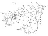
- FIG. 1is a schematic exploded view through a first embodiment of controlled discharge ostomy appliance in accordance with the invention.
- FIG. 3is a schematic rear perspective view of the first embodiment with the pouch in a stowed condition.
- FIG. 4is a schematic front perspective view of the first embodiment with the pouch deployed.
- FIG. 5is a schematic section through the first embodiment shown worn directly on the body in an operative sealing position.
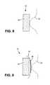
- FIG. 8is a schematic section showing in isolation a first example of stoma seal.
- FIG. 9is a schematic section showing in isolation a second example of stoma seal.
- FIG. 11is a schematic section showing in isolation a fourth example of stoma seal.
- FIG. 12is a schematic section showing a second embodiment of controlled discharge ostomy appliance.
- FIG. 13is a schematic front perspective view of the second embodiment.
- the appliancefurther comprises a stoma seal 22 .
- the stoma seal 22is a non-entrant seal that occludes a stoma 28 ( FIG. 5 ), in use, by contact with an external surface of the stoma 28 without substantially entering the stoma 28 .
- the stoma seal 22is carried within the pouch 12 by the second wall 16 .
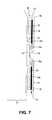
- the stoma seal 22is additionally supported at an operative sealing position ( FIGS. 3 , 5 and 7 ) at the first aperture 18 , by means of a second coupling member 24 .
- the second coupling member 24is disposed, or nests, radially within the first coupling member 20 .
- the first and second coupling members 20 and 24may optionally be coaxial, and further optionally concentric.
- the first and second coupling members 20 and 24may be separate items, or they may initially be integral with each other and coupled by one or more frangible bridges or connections 26 .
- the first and second coupling members 20 and 24are configured to couple to one or more counterpart coupling surfaces or elements (indicated in phantom).
- the second coupling member 24is separable from its counterpart surface or element without separating the first coupling member 20 , to allow the stoma seal 22 to be displaced to a non-sealing position ( FIG. 6 ), leaving the appliance attached via the first coupling member 20 .
- the stoma seal 22remains carried by the second wall 16 , as mentioned above.
- Such an arrangementenables the seal 22 to be manipulated through the second wall 16 without having to remove or open the pouch 12 to access the stoma seal 22 directly.
- the first and second coupling members 20 and 24may be selected from adhesive, mechanical (e.g. interference or interlock fit) or magnetic.
- the first and second coupling members 20 and 24may be of the same type, e.g. both adhesive, or they may be of different types.
- the coupling members 20 and 24may comprise skin-compatible adhesive for direct attachment to skin 30 as the counterpart surface for mounting the appliance at the stoma 28 ( FIG. 5 ).
- all types of coupling membermay be configured for attachment to a counterpart element 32 that is part of a body fitment 34 to which the coupling members 20 and 24 are configured to attach.
- the body fitment 34comprises, for example, a layer or pad of skin-compatible adhesive 36 facing towards the body, and the counterpart surface or element 32 facing towards the appliance 10 .
- FIG. 7illustrates a single or common counterpart element 32 for both coupling members 20 and 24 , although the body fitment 34 could, if desired, comprise respective different or distinct counterpart coupling elements/surfaces for the first and second coupling members 20 and 24 .
- the coupling member 20 or 24may comprise adhesive
- the counterpart element 32may comprise a non-adhesive landing surface; alternatively the adhesive may be provided on the counterpart element 32 and the coupling member 20 or 24 may comprise a non-adhesive landing surface; alternatively both the coupling member 20 or 24 and the counterpart element may be adhesive.
- the body fitment 34may be of a type that is separate or separable from the appliance 10 . Such a body fitment 34 may remain worn on the skin 30 allowing the appliance 10 to be removed and interchanged with a replacement appliance without removing the body fitment 34 from the skin. Such an arrangement may be referred to as “two-piece”.
- the body fitment 34may be intended to form a non-separable attachment to the first coupling member 20 at least after the first time that the body fitment is assembled to engage with the first coupling member 20 .
- Such an arrangementmay be referred to as “assemblable one-piece”.
- the term non-separablemay mean a connection sufficiently strong that the appliance 10 cannot easily be separated from the body fitment 34 (i) at least while worn on the body and/or (ii) without risk of damage to one or both components.
- the first coupling member 20may comprise an adhesive forming a bond that is stronger than the adhesive attachment between the adhesive pad 36 and the wearer's skin 30 .
- the bond for the first coupling member 20may be substantially permanent.
- the non-separable attachmentmay be mechanical, for example, formed by a strong non-separable interlock, e.g. stronger than the adhesive bond to the body.
- the second coupling member 24is (as mentioned above) configured to be separable from the body fitment 34 in order to allow the seal 22 to be moved to a non-sealing position.
- the body fitment 34may be wholly separate from the appliance prior to assembling the body fitment 34 to the appliance 10 .
- the body fitment 34may be captive to the appliance 10 , for example attached by a flexible or articulating link or joint 38 .
- the body fitment 34 and the first and second coupling members 20 and 24may comprise portions of an integral web that flexes at a region between the body fitment 34 and the first and second coupling members 20 and 24 .
- the webmay define or include the aforementioned frangible connections between the first and second coupling members 20 and 24 .
- the adhesive pad 36optionally includes a moldable zone 36 a around the stoma 28 , and a non-moldable zone 36 b circumscribing the moldable zone 36 a .
- the moldable zone 36 apermits a user to manually shape an aperture in the adhesive to form a custom fit to the unique shape of the individual ostomate's stoma 28 .
- the moldable and non-moldable zones 36 a and 36 bare integral portions of the same pad 36 .
- the moldable zone 36 amay be manually shaped by rolling or folding back the inner rim of adhesive towards the face of the adhesive pad 36 a facing away from the body.
- the face of adhesive facing towards away from the bodymay comprise exposed adhesive to facilitate adhesive anchoring of the rim in its rolled or folded back condition, and thereby hold the moldable zone 36 a in its molded shape.
- the provision of the moldable zone 36 a on a body fitment that is (at least initially) distinct from and/or uncoupled with respect to the coupling members 20 and 24 of the appliance 10facilitates access to and molding of the adhesive pad 36 from the non-body-facing side (i.e. the side normally facing the first and second coupling members 20 and 24 ).
- the body fitment 34 with a moldable zone 36 amay be used either as a body fitment that is separate and/or separable from the appliance, or captive to the appliance.
- stoma seal 22is envisaged.
- the stoma seal 22is of an external or non-entrant type that seals against the external tissue of the stoma, without penetrating or entering substantially the stoma lumen.
- a first example of stoma seal 22comprises a resilient member 40 .
- the resilient member 40may directly contact the stoma 28 in use ( FIG. 8 ), or the resilient member 40 may optionally be covered by a seal membrane 42 ( FIG. 9 ) that faces and contacts the stoma 28 in use.
- the seal membrane 42may be of material that is substantially impervious to liquid and gas, in order to prevent effluent and flatus from contacting the resilient member 40 . In that case, flatus exiting the stoma escapes along the interface between the membrane 42 and the stoma 28 to vent through a flatus vent (described later).
- the seal membrane 42may of substantially liquid impervious, gas permeable material, in order to allow flatus to pass through the seal membrane 42 to a flatus vent.
- the seal membrane 42may either be distinct and/or separate from the resilient member 40 , it may be attached integrally to the resilient member 40 , for example, by adhesive bonding or lamination.
- the seal membrane 42may optionally form part of a chamber 44 enclosing the resilient member 40 .
- the chamber 44may be substantially fluid-tight, except for fluid flow controlled through one or more ports 46 .
- the ports 46may be configured to provide a fluid-damped dynamic response to an increase and/or decrease in degree of stoma protrusion.
- the fluid-damped responsemay temporarily increase the seal contact pressure to resist a temporary challenge from the stoma, for example, caused by flatus discharge or peristomal action.
- the ports 46also allow pressure equalization over time to prevent excess pressure being applied for a prolonged period.
- the resilient member 40may be of polymeric foam.
- the foammay be open-cell foam, closed-cell foam, a memory foam, or a mix of both.
- the membrane 42may provide a smooth surface or skin for the cellular structure of the foam.
- the foammay have a Shore A hardness of less than 80, preferably less than 60, more preferably less than 50, or optionally less than 40 (especially if used with the seal membrane 42 ).
- the foammay optionally be of hydrophilic material, such that the foam absorbs moisture rapidly. The absorption results in expansion of the foam, causing the sealing effect to tighten against the stoma.
- hydrophilic materialmay be still be used if, for example, the membrane 42 (or at least a portion of the membrane surface) is liquid permeable to allow stomal fluid to reach the foam.
- resilient member 40can be selected from a hydrophobic foam.
- the stoma seal 22may optionally be coated with an adhesive ( 48 in FIG. 9 ) to enhance the seal effect against the stoma 28 .
- the adhesivecan be applied to a portion of the seal surface or the entire seal surface.
- Adhesivemay be selected from families comprising mucoadhesives and/or hydrocolloids which have been shown to be safe in providing the seal to mucosa membrane such as a stoma 28 .
- a further example of stoma seal 22comprises a gel or gel-forming material 50 .
- the gelcan be silicone gel, TPE gel, acrylic gel, hydrogel, hydrofiber (available from ConvaTec), etc.
- the gelprovides a soft, compliant, skin-friendly seal in contact directly with the surface of the stoma 28 . It is also envisaged that, in place of the adhesive 48 ( FIG. 9 ), a gel or gel-forming material be applied as a surface coating to the seal 22 .
- embodiments of the present inventionare engineered to enhance control of the sealing pressure exerted between the seal 22 and the stoma 28 .
- all of the sealing functionis focused at the external surface of the stoma 28 .
- effluentis already close to escaping from the stoma 28 .
- an internal seale.g. a plug or bung
- an external seal 22 used in the present embodimentsis preferred as it can avoid complications and risks of an indwelling device.
- the sealing pressureshould be sufficient to counter the pressure of effluent at the stoma mouth.
- the sealshould avoid prolonged application of excessive pressure, in order to avoid (i) any concerns over reduced blood flow in the stoma tissue, and/or (ii) any concerns regarding necrosis of stoma tissue.
- a first techniquepositions the stoma seal 22 relative to the aperture 18 such that, when the appliance 10 is fitted in an operative wear position at the stoma 28 , the stoma seal 22 does not touch, or does only slightly touch, the stoma 28 .
- the sealing forcemay be no more than 1 psi, or preferably no more than 0.8 psi.
- the sealing pressuremay be no more than 2 psi (103.4 mm Hg).
- the ability to avoid continuous application of sealing pressurecan reduce any impact that wearing a stoma seal may have on the stoma 28 itself.
- the appliance 10can benefit from controlled discharge capability, but with the stoma-friendliness nearly matching that of a conventional ostomy pouch. If instead it is desired to maintain some degree of continuous sealing contact, e.g. for effluent that has a high proportion of liquid, the stoma seal 22 may be disposed closer to the aperture 18 , for example, nearly flush with the surface of the first and second coupling members 20 and 24 (as indicated for example in FIG. 3 ).
- a second control techniqueis to configure the stoma seal 22 to be resilient yet soft and/or compliant.
- the stoma sealis resiliently deformable, and is configured to generate a resilience reaction pressure of not more than about 2 psi, optionally not more than about 1 psi, further optionally not more than about 0.8 psi, when the stoma seal is compressed.
- a relatively soft stoma sealcan provide excellent conformity to closely follow the contour of the stoma, while maintaining resilient contact with the contour.
- Such a soft characteristicis especially envisaged in combination with the use of foam for the resilient member 40 .
- a third control techniqueuses the seal pressure exerted between the stoma seal 22 and the stoma 28 being supported or transferred, at least partly, by the second coupling member 24 .
- the second coupling member 24bears at least a majority of the seal pressure, more preferably substantially all of the seal pressure (e.g. at least 90%).
- the second coupling member 24may be configured to release or separate from a coupled condition with the counterpart member or surface 30 or 32 when the reaction pressure (or force) transmitted through the second coupling member 24 exceeds a seal threshold.
- the seal threshold of outer coupling membermay be at least 10 N/in shear strength (i.e., 0 degree peel) or 5 psi such that the device will remain attached to the peristomal skin even though the inner coupling member is separated or released its contact against stoma.
- the use of such selective coupling strength for the inner and outer coupling membercan ensure that the seal pressure applied to the stoma 28 by the stoma seal 22 does not exceed a safe level. In the event of the reaction to the seal pressure exceeding the seal threshold, the inner coupling member 24 will begin to separate or release, thereby to relieve the seal pressure.
- the seal thresholdmay be less than 50%, more preferably less than 20% of a corresponding threshold at which the outer coupling member 20 releases from the counterpart member or surface 30 or 32 to which the outer coupling member 20 couples in use.
- the second coupling member 24may, for example, be sized or carry an adhesive configured to provide the desired coupling strength.
- the stoma seal 22is accommodated by a seal holder 60 .
- the stoma seal 22projects from the holder through a second aperture 62 in the front wall 16 towards the first aperture 18 in the rear wall 14 .
- the second aperture 62is smaller in diameter than the first aperture 18 .
- the second aperture 62is sized to enable at least a stoma engaging part of the stoma seal 22 to project therethrough.
- the holder 60comprises a mounting flange 64 from which depends a well or cup 66 for accommodating at least partly the seal 22 .
- the mounting flangemay be annular in shape, and sized to fit against the front wall 16 circumscribing the second aperture 62 .
- the holder 60may be substantially rigid, but it is preferred that the holder 60 have a self-supporting shape yet be deformable and/or flexible for the sake of comfort.
- the holdermay, for example, be thermoformed.
- the holder 60also comprises one or more wells or recesses 68 for accommodating a deodorizing filter 70 and, optionally, a filter protection member 72 .
- the filter protection member 72serves to obstruct any semi-solid stool that may have leaked past the seal 22 from reaching the filter 70 , while generally allowing flatus gas to pass relatively unhindered to the filter 70 .
- the filter protection member 72may comprise open-cell foam, the pores of which tend to trap semi-solid stool while allowing flatus gas to pass through.
- the recess 68may comprises one or more exit apertures communicating with the filter 70 for allowing deodorized gas to exit from the holder 60 .
- the holder 60comprises one or more radial castellations 74 .
- the castellations 74define radial channels through which flatus may pass between the surface of the holder 60 and the stoma seal 22 , in order to reach the filter 70 and/or protection member 72 .
- the castellations 74also provide upstands for bearing against the stoma seal 22 , in order to transmit the seal reaction pressure from the stoma seal 22 , through the holder 60 and ultimately to the second coupling member 24 .
- the holder 60is attached, for example, by adhesive or welding, to the front wall 16 around the second aperture 62 .
- the second coupling member 24is likewise attached, by adhesive or welding, to the opposite face of the front wall 16 to provide a connection between the holder 60 and the second coupling member 24 .
- the holdercould, if desired, be attached directly to the second coupling member 24 .
- the present constructionmay facilitate more straightforward manufacture.
- the holder 60may be attached to the front wall 16 after which the front wall 16 may be attached, by adhesive or welding, to the rear wall 14 .
- the stoma seal 22may be mounted to the holder 60 by inserting the stoma seal 22 through the first and second apertures 18 and 62 , and the first and second coupling members 20 and 24 (which may be formed as an integral piece) may be attached substantially simultaneously to the respective surfaces of the rear and front walls 14 and 16 .
- the appliance 10further comprises a front fascia or cover 80 .
- the cover 80may be of comfortable flexible material, such as rubber or silicone.
- the cover 80may be shaped to accommodate the projecting well or cup shape of the seal holder 60 .
- the cover 80comprises flatus vent apertures 76 through which the deodorized flatus, after exiting the holder, can vent externally of the appliance 10 (as indicated by the arrows in FIG. 5 ).
- the cover 80is dimensioned to cover substantially the entire upper portion 90 of the pouch 12 .
- the pouch 12comprises the upper portion 90 ( FIG. 1 ) and a lower portion 94 ( FIG. 1 ) that is movable, relative to the upper portion 90 , between a stowed and/or compact condition ( FIGS. 2 and 5 ), and a distended and/or deployed condition ( FIGS. 4 and 6 ).
- the upper portion 90provides the apertures 18 and 62 .
- the lower portion 94is folded or rolled upwardly towards the upper portion 90 to define a coil.
- the coilis held in its compact condition by any suitable means, such as by being received in a holding pocket 84 at the lower end 82 of the cover 80 .
- Other retention meansmay include: hook and loop (or hook-hook) material; a magnetic fastener; interlocking or mating fastener elements (such as interlocking lips); pressure sensitive peelable adhesive.
- the lower portion 94In its deployed condition, the lower portion 94 depends from the upper portion 90 to provide a collection volume for effluent.
- a prosthetic ostomy appliancecan be designed with a soft cover 80 and a compact device in a condition shown in FIGS. 2 and 5 .
- Such a designis shown to be functional, discreet, and aesthetically appealing to ostomy users.
- the lower portion 94is distended downwardly, and the one or more folded-in side regions 96 unfold laterally (about the broken lines in FIG. 4 ) to define the fully distended shape.
- the large width of the lower portion 94can provide a significant collection volume in a similar manner to a conventional ostomy pouch, yet fold to a smaller width compact form to be accommodated at the cover 80 .
- the pouch 10may be deployed either manually or automatically when the second coupling member 24 is disengaged to displace the stoma seal 22 and allow escape of stomal effluent into the pouch 10 .
- the action of manipulating the second coupling member 24 through the cover 80 bayreleases the lower portion 94 to distend.
- the weight of effluent collecting within the pouch 10may be sufficient to release the lower portion 94 to distend.
- the usermay manually release the lower portion 94 to distend, such that the appliance permits the user to decide and control the desired configuration of the appliance.
- a pulling tab 96( FIGS. 5 and 6 ) is added to facilitate a manual separation of the inner coupling member 24 .
- One end of such a pulling tabis connected to the front wall 16 or mounting flange 64 .
- the other endis extended out of the soft cover 80 in order for an easy manipulation by ostomates in use.
- the pulling tab extended outside of soft cover 80can be attached to the front cover by an adhesive, mechanical seal, or a magnetic seal.
- a peelable seal or a Velcrocan be used to fasten the free moving end of pulling tab 96 to the soft cover 80 .
- FIGS. 12 and 13illustrate a second example of controlled discharge ostomy appliance, and the same reference numerals denote equivalent features. Whether or not shown, the second embodiment may include any combination of features from the first embodiment (for example, the side expanding lower portion of the pouch, not shown explicitly in FIGS. 12 and 13 ; and/or the body fitment not shown explicitly in FIGS. 12 and 13 ).
- An annular foam member 102 circumscribing the seal 22acts as a phase separator allowing flatus to pass therethrough to the deodorizing filter 70 , while obstructing passage of any solid or semi-liquid stool that might accidentally leak past the stoma seal 22 .
- the foam member 102may be omitted, and the seal membrane 42 comprise, at least over a part of its surface, a gas-permeable liquid-impermeable membrane material to allow flatus to pass directly through the membrane 42 to the deodorizing filter 70 .
- manipulation tabs 104may be provided on, for example, the cover/holder 100 and the first (rear) pouch wall 14 to enable a user to apply a separation pressure to the second coupling member 24 through the appliance walls, without having to access the second coupling member 24 directly. Similar manipulation tabs may also be used with the first embodiment described herein.
Landscapes
- Health & Medical Sciences (AREA)
- Epidemiology (AREA)
- Nursing (AREA)
- Orthopedic Medicine & Surgery (AREA)
- Engineering & Computer Science (AREA)
- Biomedical Technology (AREA)
- Heart & Thoracic Surgery (AREA)
- Vascular Medicine (AREA)
- Life Sciences & Earth Sciences (AREA)
- Animal Behavior & Ethology (AREA)
- General Health & Medical Sciences (AREA)
- Public Health (AREA)
- Veterinary Medicine (AREA)
- Chemical & Material Sciences (AREA)
- Dispersion Chemistry (AREA)
- Orthopedics, Nursing, And Contraception (AREA)
Abstract
Description
Claims (32)
Priority Applications (13)
| Application Number | Priority Date | Filing Date | Title |
|---|---|---|---|
| US13/282,015US8684982B2 (en) | 2010-10-29 | 2011-10-26 | Controlled evacuation ostomy appliance |
| EP17179528.9AEP3295903A1 (en) | 2010-10-29 | 2011-10-27 | Controlled evacuation ostomy appliance |
| RU2013124805/14ARU2603429C2 (en) | 2010-10-29 | 2011-10-27 | Device for controlled release from stoma |
| AU2011319838AAU2011319838B2 (en) | 2010-10-29 | 2011-10-27 | Controlled evacuation ostomy appliance |
| PCT/US2011/058019WO2012058388A1 (en) | 2010-10-29 | 2011-10-27 | Controlled evacuation ostomy appliance |
| PL11837067TPL2632396T3 (en) | 2010-10-29 | 2011-10-27 | Controlled evacuation ostomy appliance |
| ES11837067.5TES2641066T3 (en) | 2010-10-29 | 2011-10-27 | Controlled evacuation ostomy device |
| CN201180063120.0ACN103281992B (en) | 2010-10-29 | 2011-10-27 | Controlled voiding ostomy appliances |
| CA2818747ACA2818747C (en) | 2010-10-29 | 2011-10-27 | Controlled evacuation ostomy appliance |
| CN201610999328.8ACN106901890B (en) | 2010-10-29 | 2011-10-27 | The ostomy appliance of controlled excretion |
| DK11837067.5TDK2632396T3 (en) | 2010-10-29 | 2011-10-27 | Controlled discharge stoma device |
| EP11837067.5AEP2632396B1 (en) | 2010-10-29 | 2011-10-27 | Controlled evacuation ostomy appliance |
| NZ611063ANZ611063A (en) | 2010-10-29 | 2011-10-27 | Controlled evacuation ostomy appliance |
Applications Claiming Priority (2)
| Application Number | Priority Date | Filing Date | Title |
|---|---|---|---|
| US40794310P | 2010-10-29 | 2010-10-29 | |
| US13/282,015US8684982B2 (en) | 2010-10-29 | 2011-10-26 | Controlled evacuation ostomy appliance |
Publications (2)
| Publication Number | Publication Date |
|---|---|
| US20120283678A1 US20120283678A1 (en) | 2012-11-08 |
| US8684982B2true US8684982B2 (en) | 2014-04-01 |
Family
ID=45994390
Family Applications (1)
| Application Number | Title | Priority Date | Filing Date |
|---|---|---|---|
| US13/282,015ActiveUS8684982B2 (en) | 2010-10-29 | 2011-10-26 | Controlled evacuation ostomy appliance |
Country Status (11)
| Country | Link |
|---|---|
| US (1) | US8684982B2 (en) |
| EP (2) | EP3295903A1 (en) |
| CN (2) | CN106901890B (en) |
| AU (1) | AU2011319838B2 (en) |
| CA (1) | CA2818747C (en) |
| DK (1) | DK2632396T3 (en) |
| ES (1) | ES2641066T3 (en) |
| NZ (1) | NZ611063A (en) |
| PL (1) | PL2632396T3 (en) |
| RU (1) | RU2603429C2 (en) |
| WO (1) | WO2012058388A1 (en) |
Cited By (51)
| Publication number | Priority date | Publication date | Assignee | Title |
|---|---|---|---|---|
| US20100241092A1 (en)* | 2007-05-11 | 2010-09-23 | Convatec Technologies Inc. | Ostomy appliance |
| USD754332S1 (en)* | 2012-08-13 | 2016-04-19 | Andreas Fahl Medizintechnik—Vertrieb GmbH | Plaster for tracheostoma |
| US20190175386A1 (en)* | 2016-06-07 | 2019-06-13 | Stephanie MONTY | Dressing for concealing a structure on a human body |
| US20200330258A1 (en)* | 2017-12-22 | 2020-10-22 | Coloplast A/S | Sensor assembly part and a base plate for a medical appliance and a method for manufacturing a sensor assembly part and a base plate |
| US20200383818A1 (en)* | 2017-12-22 | 2020-12-10 | Coloplast A/S | Base plate and a sensor assembly part for a medical appliance and a method for manufacturing a base plate and sensor assembly part |
| US20210015653A1 (en)* | 2017-12-22 | 2021-01-21 | Coloplast A/S | Base plate and a sensor assembly part for a medical appliance |
| US20210085511A1 (en)* | 2017-12-22 | 2021-03-25 | Coloplast A/S | Sensor assembly part and a base plate for a medical appliance and a method for manufacturing a base plate or a sensor assembly part |
| US11051971B2 (en)* | 2015-10-20 | 2021-07-06 | Coloplast A/S | Ostomy appliance |
| US20210361464A1 (en)* | 2017-12-22 | 2021-11-25 | Coloplast A/S | Coupling part with a hinge for a medical base plate and sensor assembly part |
| US20210369488A1 (en)* | 2017-12-22 | 2021-12-02 | Coloplast A/S | Medical appliance with angular leakage detection |
| US20210369489A1 (en)* | 2017-12-22 | 2021-12-02 | Coloplast A/S | Base plate for a medical appliance and a sensor assembly part for a base plate and a method for manufacturing a base plate and sensor assembly part |
| US20220054294A1 (en)* | 2010-09-30 | 2022-02-24 | Convatec Technologies Inc. | Ostomy pouch with filtering system |
| USD947373S1 (en)* | 2019-12-06 | 2022-03-29 | Hollister Incorporated | Convex insert for ostomy appliance |
| US20220304844A1 (en)* | 2019-06-14 | 2022-09-29 | Hollister Incorporated | Leakage detection system for ostomy appliance |
| US11534323B2 (en) | 2017-12-22 | 2022-12-27 | Coloplast A/S | Tools and methods for placing a medical appliance on a user |
| US11540937B2 (en) | 2017-12-22 | 2023-01-03 | Coloplast A/S | Base plate and sensor assembly of a medical system having a leakage sensor |
| US11547596B2 (en) | 2017-12-22 | 2023-01-10 | Coloplast A/S | Ostomy appliance with layered base plate |
| US11589811B2 (en) | 2017-12-22 | 2023-02-28 | Coloplast A/S | Monitor device of a medical system and associated method for operating a monitor device |
| US11607334B2 (en) | 2017-12-22 | 2023-03-21 | Coloplast A/S | Base plate for a medical appliance, a monitor device and a system for a medical appliance |
| US11612508B2 (en) | 2017-12-22 | 2023-03-28 | Coloplast A/S | Sensor assembly part for a medical appliance and a method for manufacturing a sensor assembly part |
| US11612512B2 (en) | 2019-01-31 | 2023-03-28 | Coloplast A/S | Moisture detecting base plate for an ostomy appliance and a system for determining moisture propagation in a base plate and/or a sensor assembly part |
| US11628084B2 (en) | 2017-12-22 | 2023-04-18 | Coloplast A/S | Sensor assembly part and a base plate for a medical appliance and a device for connecting to a base plate or a sensor assembly part |
| US11627891B2 (en) | 2017-12-22 | 2023-04-18 | Coloplast A/S | Calibration methods for medical appliance tools |
| US20230160771A1 (en)* | 2020-05-27 | 2023-05-25 | Hollister Incorporated | Ostomy leakage detection system |
| US11701248B2 (en) | 2017-12-22 | 2023-07-18 | Coloplast A/S | Accessory devices of a medical system, and related methods for communicating leakage state |
| US11786392B2 (en) | 2017-12-22 | 2023-10-17 | Coloplast A/S | Data collection schemes for an ostomy appliance and related methods |
| US11819443B2 (en) | 2017-12-22 | 2023-11-21 | Coloplast A/S | Moisture detecting base plate for a medical appliance and a system for determining moisture propagation in a base plate and/or a sensor assembly part |
| US11865029B2 (en) | 2017-12-22 | 2024-01-09 | Coloplast A/S | Monitor device of a medical system having a connector for coupling to both a base plate and an accessory device |
| US11872154B2 (en) | 2017-12-22 | 2024-01-16 | Coloplast A/S | Medical appliance system, monitor device, and method of monitoring a medical appliance |
| US11883317B2 (en)* | 2020-04-15 | 2024-01-30 | Convatec Limited | Ostomy appliance |
| US11890219B2 (en) | 2014-04-17 | 2024-02-06 | Coloplast A/S | Thermoresponsive skin barrier appliances |
| US11918506B2 (en) | 2017-12-22 | 2024-03-05 | Coloplast A/S | Medical appliance with selective sensor points and related methods |
| US11931285B2 (en) | 2018-02-20 | 2024-03-19 | Coloplast A/S | Sensor assembly part and a base plate for a medical appliance and a device for connecting to a base plate and/or a sensor assembly part |
| US11986418B2 (en) | 2017-12-22 | 2024-05-21 | Coloplast A/S | Medical system and monitor device with angular leakage detection |
| US11998474B2 (en) | 2018-03-15 | 2024-06-04 | Coloplast A/S | Apparatus and methods for navigating ostomy appliance user to changing room |
| US11998473B2 (en) | 2017-12-22 | 2024-06-04 | Coloplast A/S | Tools and methods for cutting holes in a medical appliance |
| US12029582B2 (en) | 2018-02-20 | 2024-07-09 | Coloplast A/S | Accessory devices of a medical system, and related methods for changing a medical appliance based on future operating state |
| US12064369B2 (en) | 2017-12-22 | 2024-08-20 | Coloplast A/S | Processing schemes for an ostomy system, monitor device for an ostomy appliance and related methods |
| US12064258B2 (en) | 2018-12-20 | 2024-08-20 | Coloplast A/S | Ostomy condition classification with image data transformation, devices and related methods |
| US12147357B2 (en) | 2020-04-14 | 2024-11-19 | Coloplast A/S | Personal care system with monitor device and related methods |
| US12165312B2 (en) | 2018-12-20 | 2024-12-10 | Coloplast A/S | Ostomy condition classification with masking, devices and related methods |
| US12171572B2 (en) | 2017-12-22 | 2024-12-24 | Coloplast A/S | Accessory devices of a medical system, and related methods for communicating operating state |
| US12208029B2 (en) | 2018-02-20 | 2025-01-28 | Coloplast A/S | Base plate having a mechanical and electrical connector |
| US12226229B2 (en) | 2018-03-15 | 2025-02-18 | Coloplast A/S | Methods of configuring ostomy notifications and related accessory devices |
| US12232998B2 (en) | 2019-01-31 | 2025-02-25 | Coloplast A/S | Application of a stomal sensor patch |
| US12232997B2 (en) | 2018-08-15 | 2025-02-25 | Coloplast A/S | Accessory device of a medical system and related methods for issue identification |
| US12257172B2 (en) | 2019-02-28 | 2025-03-25 | Coloplast A/S | Sensor patch for attachment to a base plate |
| US12272449B2 (en) | 2017-12-22 | 2025-04-08 | Coloplast A/S | Data transmission schemes for a medical system, monitor device for a medical appliance and related methods |
| US12310877B2 (en) | 2019-01-31 | 2025-05-27 | Coloplast A/S | Sensor patch for an ostomy appliance |
| US12376984B2 (en) | 2019-01-31 | 2025-08-05 | Coloplast A/S | Stomal sensor patch |
| US12440369B2 (en)* | 2020-04-15 | 2025-10-14 | Convatec Limited | Ostomy appliance |
Families Citing this family (29)
| Publication number | Priority date | Publication date | Assignee | Title |
|---|---|---|---|---|
| CA2916746C (en) | 2006-10-17 | 2018-11-27 | C.R. Bard, Inc. | Waste management system |
| US8777912B2 (en) | 2007-07-22 | 2014-07-15 | C. R. Bard, Inc. | Waste management system |
| US10285847B2 (en)* | 2011-09-29 | 2019-05-14 | Convatec Technologies Inc. | Ostomy pouch with filtering system |
| NO334400B1 (en)* | 2010-11-25 | 2014-02-24 | Erland As | Stomach leakage collection device, mounting plate and assembly thereof |
| JP6783519B2 (en)* | 2012-11-20 | 2020-11-11 | コンバテック・テクノロジーズ・インコーポレイテッドConvatec Technologies Inc | Improvement of One Piece Ostomy Pouch |
| GB2512655B (en)* | 2013-04-05 | 2017-10-25 | Salts Healthcare Ltd | Ostomy appliance |
| BR112015032821B1 (en) | 2013-07-18 | 2021-12-14 | Coloplast A/S | PRESSURE MONITORING METHOD, AND, OSTOMY UTENSIL |
| IES86559B2 (en)* | 2014-02-20 | 2015-07-01 | Brendan Magee | Apparatus to protect abdominal stoma and prevent ostomy pouch from leaking |
| DK3134040T3 (en) | 2014-04-24 | 2021-05-25 | Convatec Technologies Inc | Ostomy bag filter system |
| US9907689B2 (en)* | 2014-11-14 | 2018-03-06 | Michael Thomas Persichina | Stoma protection guard for ostomy pouch |
| KR101961742B1 (en)* | 2014-12-12 | 2019-03-25 | 가부시키가이샤 후지나미 | Defecation bag and method for manufacturing same |
| CN107206118A (en)* | 2015-01-28 | 2017-09-26 | 霍利斯特股份有限公司 | For the stoma edge device for moistening the adhesive of tissue and being made using the adhesive |
| DK178391B1 (en) | 2015-03-18 | 2016-10-17 | Multi-Lock Aps | An ostomy appliance |
| BR112018006211A2 (en)* | 2015-10-08 | 2018-10-09 | Coloplast A/S | lateral body member of an ostomy apparatus. |
| RU2724410C2 (en)* | 2015-10-08 | 2020-06-23 | Колопласт А/С | Body-facing stoma adapter element |
| GB2566721B (en)* | 2017-09-22 | 2020-07-15 | Salts Healthcare Ltd | An ostomy appliance |
| RU2020126922A (en)* | 2018-01-19 | 2022-02-21 | Колопласт А/С | STOMA COVER SYSTEM |
| US12178738B2 (en) | 2018-01-19 | 2024-12-31 | Ostovalve Llc | Regulating flow from a stoma on a patient |
| US11771585B2 (en) | 2018-01-19 | 2023-10-03 | Ostovalve, Llc | Devices, systems and methods for regulating flow from a stoma on a patient |
| EP3773368B1 (en) | 2018-04-10 | 2022-08-31 | Association for the Advancement of Tissue Engineering and Cell Based Technologies & Therapies (A4TEC) - Associacão | Medical device for controlling the release of waste content from a subject |
| US11517469B2 (en) | 2019-01-31 | 2022-12-06 | Coloplast A/S | Base plate and sensor assembly part of an ostomy system having a moisture sensor |
| CA3140906A1 (en)* | 2019-06-11 | 2020-12-17 | Convatec Technologies Inc. | Urine collection bags for use with catheter products, kits incorporating the same, and methods therefor |
| WO2021064407A1 (en)* | 2019-10-04 | 2021-04-08 | Convatec Limited | Ostomy appliance |
| CN114502113B (en)* | 2019-10-04 | 2024-07-02 | 康沃特克有限公司 | Ostomy appliance |
| AU2020358811A1 (en) | 2019-10-04 | 2022-03-31 | Convatec Limited | Ostomy appliance |
| US12303423B2 (en) | 2019-10-04 | 2025-05-20 | Convatec Limited | Ostomy appliance |
| EP4146128B1 (en)* | 2020-05-08 | 2025-06-04 | Hollister Incorporated | Ostomy appliance with fold-over filter |
| GB202008258D0 (en)* | 2020-06-02 | 2020-07-15 | Convatec Ltd | An ostomy pounch |
| US20210369484A1 (en)* | 2020-06-02 | 2021-12-02 | Convatec Limited | Ostomy Pouch |
Citations (8)
| Publication number | Priority date | Publication date | Assignee | Title |
|---|---|---|---|---|
| US4411659A (en)* | 1982-03-16 | 1983-10-25 | Hollister Incorporated | Drainable collection pouch and filter assembly therefor |
| US4889534A (en)* | 1986-12-04 | 1989-12-26 | Hollister Incorporated | Ostomy appliance with three-lement coupling ring assembly |
| US6312415B1 (en)* | 1997-05-26 | 2001-11-06 | Coloplast A/S | Ostomy appliance |
| US6572588B1 (en)* | 2000-03-10 | 2003-06-03 | Venetec International, Inc. | Medical anchoring system |
| US20040181197A1 (en)* | 2002-03-27 | 2004-09-16 | Cline John B. | Controlled evacuation ostomy device with external seal |
| US20040267198A1 (en)* | 2001-10-12 | 2004-12-30 | Jan Torstensen | Sealing device |
| US20060058576A1 (en)* | 2004-09-13 | 2006-03-16 | Geraint Davies | Stoma plug |
| WO2008141180A1 (en)* | 2007-05-11 | 2008-11-20 | Bristol-Myers Squibb Company | Ostomy appliance |
Family Cites Families (13)
| Publication number | Priority date | Publication date | Assignee | Title |
|---|---|---|---|---|
| US3817893A (en)* | 1972-12-22 | 1974-06-18 | Du Pont | Thermoplastic elastomeric compositions |
| US5618276A (en)* | 1996-02-14 | 1997-04-08 | Hollister Incorporated | Ostomy appliance with convex pressure ring |
| US5607413A (en)* | 1996-03-12 | 1997-03-04 | Dansac A/S | Convex ostomy faceplate with floating flange and finger recess |
| DK173680B1 (en)* | 1999-02-10 | 2001-06-11 | Coloplast As | ostomy Prop |
| DK173962B1 (en)* | 1999-05-06 | 2002-03-18 | Coloplast As | An ostomy siting device |
| DK174693B1 (en)* | 2001-06-15 | 2003-09-15 | Coloplast As | Storm interior |
| US7564871B2 (en)* | 2002-10-25 | 2009-07-21 | At&T Corp. | Network routing method and system utilizing label-switching traffic engineering queues |
| DK1652497T3 (en)* | 2004-10-27 | 2008-06-23 | Ostomycure As | Adapter, cover and connector for ostomy bags |
| NZ551481A (en)* | 2005-11-30 | 2008-08-29 | Bristol Myers Squibb Co | Controlled evacuation ostomy appliance |
| US8070737B2 (en)* | 2006-01-06 | 2011-12-06 | Convatec Technologies Inc. | Seal for controlled evacuation ostomy appliance |
| WO2008124716A2 (en)* | 2007-04-09 | 2008-10-16 | Bristol-Myers Squibb Company | Ostomy pouch appliance |
| US20100114044A1 (en)* | 2007-04-09 | 2010-05-06 | Cramer Kathryn E | Adhesive body fitment for ostomy appliane |
| CA2737221C (en)* | 2008-09-15 | 2014-12-23 | Hollister Incorporated | Ostomy pouch |
- 2011
- 2011-10-26USUS13/282,015patent/US8684982B2/enactiveActive
- 2011-10-27EPEP17179528.9Apatent/EP3295903A1/ennot_activeWithdrawn
- 2011-10-27AUAU2011319838Apatent/AU2011319838B2/ennot_activeCeased
- 2011-10-27RURU2013124805/14Apatent/RU2603429C2/enactive
- 2011-10-27CNCN201610999328.8Apatent/CN106901890B/ennot_activeExpired - Fee Related
- 2011-10-27CNCN201180063120.0Apatent/CN103281992B/enactiveActive
- 2011-10-27DKDK11837067.5Tpatent/DK2632396T3/enactive
- 2011-10-27CACA2818747Apatent/CA2818747C/enactiveActive
- 2011-10-27ESES11837067.5Tpatent/ES2641066T3/enactiveActive
- 2011-10-27EPEP11837067.5Apatent/EP2632396B1/enactiveActive
- 2011-10-27WOPCT/US2011/058019patent/WO2012058388A1/enactiveApplication Filing
- 2011-10-27PLPL11837067Tpatent/PL2632396T3/enunknown
- 2011-10-27NZNZ611063Apatent/NZ611063A/ennot_activeIP Right Cessation
Patent Citations (8)
| Publication number | Priority date | Publication date | Assignee | Title |
|---|---|---|---|---|
| US4411659A (en)* | 1982-03-16 | 1983-10-25 | Hollister Incorporated | Drainable collection pouch and filter assembly therefor |
| US4889534A (en)* | 1986-12-04 | 1989-12-26 | Hollister Incorporated | Ostomy appliance with three-lement coupling ring assembly |
| US6312415B1 (en)* | 1997-05-26 | 2001-11-06 | Coloplast A/S | Ostomy appliance |
| US6572588B1 (en)* | 2000-03-10 | 2003-06-03 | Venetec International, Inc. | Medical anchoring system |
| US20040267198A1 (en)* | 2001-10-12 | 2004-12-30 | Jan Torstensen | Sealing device |
| US20040181197A1 (en)* | 2002-03-27 | 2004-09-16 | Cline John B. | Controlled evacuation ostomy device with external seal |
| US20060058576A1 (en)* | 2004-09-13 | 2006-03-16 | Geraint Davies | Stoma plug |
| WO2008141180A1 (en)* | 2007-05-11 | 2008-11-20 | Bristol-Myers Squibb Company | Ostomy appliance |
Cited By (90)
| Publication number | Priority date | Publication date | Assignee | Title |
|---|---|---|---|---|
| US9707120B2 (en)* | 2007-05-11 | 2017-07-18 | Convatec Technologies Inc. | Ostomy appliance |
| US20100241092A1 (en)* | 2007-05-11 | 2010-09-23 | Convatec Technologies Inc. | Ostomy appliance |
| US20220054294A1 (en)* | 2010-09-30 | 2022-02-24 | Convatec Technologies Inc. | Ostomy pouch with filtering system |
| USD754332S1 (en)* | 2012-08-13 | 2016-04-19 | Andreas Fahl Medizintechnik—Vertrieb GmbH | Plaster for tracheostoma |
| USD786424S1 (en) | 2012-08-13 | 2017-05-09 | Andreas Fahl Medizintechnik-Vertrieb Gmbh | Plaster for tracheostoma |
| USD786425S1 (en) | 2012-08-13 | 2017-05-09 | Andreas Fahl Medizintechnik - Vertrieb Gmbh | Plaster for tracheostoma |
| US11890219B2 (en) | 2014-04-17 | 2024-02-06 | Coloplast A/S | Thermoresponsive skin barrier appliances |
| US11219547B2 (en) | 2015-10-20 | 2022-01-11 | Coloplast A/S | Ostomy appliance |
| US11051971B2 (en)* | 2015-10-20 | 2021-07-06 | Coloplast A/S | Ostomy appliance |
| US20190175386A1 (en)* | 2016-06-07 | 2019-06-13 | Stephanie MONTY | Dressing for concealing a structure on a human body |
| US11793663B2 (en)* | 2016-06-07 | 2023-10-24 | Ostique Limited | Dressing for concealing a structure on a human body |
| US11786392B2 (en) | 2017-12-22 | 2023-10-17 | Coloplast A/S | Data collection schemes for an ostomy appliance and related methods |
| US20200330258A1 (en)* | 2017-12-22 | 2020-10-22 | Coloplast A/S | Sensor assembly part and a base plate for a medical appliance and a method for manufacturing a sensor assembly part and a base plate |
| US20210369489A1 (en)* | 2017-12-22 | 2021-12-02 | Coloplast A/S | Base plate for a medical appliance and a sensor assembly part for a base plate and a method for manufacturing a base plate and sensor assembly part |
| US20210361464A1 (en)* | 2017-12-22 | 2021-11-25 | Coloplast A/S | Coupling part with a hinge for a medical base plate and sensor assembly part |
| US20210085511A1 (en)* | 2017-12-22 | 2021-03-25 | Coloplast A/S | Sensor assembly part and a base plate for a medical appliance and a method for manufacturing a base plate or a sensor assembly part |
| US12433781B2 (en) | 2017-12-22 | 2025-10-07 | Coloplast A/S | Tools and methods for placing an ostomy appliance on a user |
| US12433782B2 (en) | 2017-12-22 | 2025-10-07 | Coloplast A/S | Ostomy appliance with selective sensor points and related methods |
| US11534323B2 (en) | 2017-12-22 | 2022-12-27 | Coloplast A/S | Tools and methods for placing a medical appliance on a user |
| US11540937B2 (en) | 2017-12-22 | 2023-01-03 | Coloplast A/S | Base plate and sensor assembly of a medical system having a leakage sensor |
| US11547595B2 (en)* | 2017-12-22 | 2023-01-10 | Coloplast A/S | Base plate and a sensor assembly part for a medical appliance |
| US11547596B2 (en) | 2017-12-22 | 2023-01-10 | Coloplast A/S | Ostomy appliance with layered base plate |
| US11590015B2 (en)* | 2017-12-22 | 2023-02-28 | Coloplast A/S | Sensor assembly part and a base plate for a medical appliance and a method for manufacturing a sensor assembly part and a base plate |
| US11589811B2 (en) | 2017-12-22 | 2023-02-28 | Coloplast A/S | Monitor device of a medical system and associated method for operating a monitor device |
| US11607334B2 (en) | 2017-12-22 | 2023-03-21 | Coloplast A/S | Base plate for a medical appliance, a monitor device and a system for a medical appliance |
| US11612509B2 (en) | 2017-12-22 | 2023-03-28 | Coloplast A/S | Base plate and a sensor assembly part for an ostomy appliance |
| US11612508B2 (en) | 2017-12-22 | 2023-03-28 | Coloplast A/S | Sensor assembly part for a medical appliance and a method for manufacturing a sensor assembly part |
| US12364621B2 (en) | 2017-12-22 | 2025-07-22 | Coloplast A/S | Ostomy system operable to inform an ostomate of an ostomy device condition useful in preventing leakage relative to the ostomy device |
| US11622719B2 (en) | 2017-12-22 | 2023-04-11 | Coloplast A/S | Sensor assembly part, base plate and monitor device of a medical system and associated method |
| US11628084B2 (en) | 2017-12-22 | 2023-04-18 | Coloplast A/S | Sensor assembly part and a base plate for a medical appliance and a device for connecting to a base plate or a sensor assembly part |
| US11627891B2 (en) | 2017-12-22 | 2023-04-18 | Coloplast A/S | Calibration methods for medical appliance tools |
| US11654043B2 (en)* | 2017-12-22 | 2023-05-23 | Coloplast A/S | Sensor assembly part and a base plate for a medical appliance and a method for manufacturing a base plate or a sensor assembly part |
| US12290466B2 (en) | 2017-12-22 | 2025-05-06 | Coloplast A/S | Accessory devices of an ostomy system, and related methods for communicating leakage state |
| US11679021B2 (en)* | 2017-12-22 | 2023-06-20 | Coloplast A/S | Base plate and a sensor assembly part for a medical appliance and a method for manufacturing a base plate and sensor assembly part |
| US20230210682A1 (en)* | 2017-12-22 | 2023-07-06 | Coloplast A/S | Base plate and a sensor assembly part for an ostomy appliance |
| US11701248B2 (en) | 2017-12-22 | 2023-07-18 | Coloplast A/S | Accessory devices of a medical system, and related methods for communicating leakage state |
| US11707376B2 (en)* | 2017-12-22 | 2023-07-25 | Coloplast A/S | Base plate for a medical appliance and a sensor assembly part for a base plate and a method for manufacturing a base plate and sensor assembly part |
| US11707377B2 (en)* | 2017-12-22 | 2023-07-25 | Coloplast A/S | Coupling part with a hinge for a medical base plate and sensor assembly part |
| US11717433B2 (en)* | 2017-12-22 | 2023-08-08 | Coloplast A/S | Medical appliance with angular leakage detection |
| US11730622B2 (en) | 2017-12-22 | 2023-08-22 | Coloplast A/S | Medical appliance with layered base plate and/or sensor assembly part and related methods |
| US12272449B2 (en) | 2017-12-22 | 2025-04-08 | Coloplast A/S | Data transmission schemes for a medical system, monitor device for a medical appliance and related methods |
| US20230301818A1 (en)* | 2017-12-22 | 2023-09-28 | Coloplast A/S | Leakage detection in an ostomy device |
| US20230310201A1 (en)* | 2017-12-22 | 2023-10-05 | Coloplast A/S | Adhesive ostomy base plate having a sensor assembly adapted to monitor a condition of the adhesive |
| US20210015653A1 (en)* | 2017-12-22 | 2021-01-21 | Coloplast A/S | Base plate and a sensor assembly part for a medical appliance |
| US20200383818A1 (en)* | 2017-12-22 | 2020-12-10 | Coloplast A/S | Base plate and a sensor assembly part for a medical appliance and a method for manufacturing a base plate and sensor assembly part |
| US11819443B2 (en) | 2017-12-22 | 2023-11-21 | Coloplast A/S | Moisture detecting base plate for a medical appliance and a system for determining moisture propagation in a base plate and/or a sensor assembly part |
| US11844718B2 (en) | 2017-12-22 | 2023-12-19 | Coloplast A/S | Medical device having a monitor mechanically and electrically attachable to a medical appliance |
| US11865029B2 (en) | 2017-12-22 | 2024-01-09 | Coloplast A/S | Monitor device of a medical system having a connector for coupling to both a base plate and an accessory device |
| US20240009020A1 (en)* | 2017-12-22 | 2024-01-11 | Coloplast A/S | Ostomy appliance with leakage detection |
| US11872154B2 (en) | 2017-12-22 | 2024-01-16 | Coloplast A/S | Medical appliance system, monitor device, and method of monitoring a medical appliance |
| US12232999B2 (en)* | 2017-12-22 | 2025-02-25 | Coloplast A/S | Base plate and a sensor assembly part for an ostomy appliance |
| US20210369488A1 (en)* | 2017-12-22 | 2021-12-02 | Coloplast A/S | Medical appliance with angular leakage detection |
| US11918506B2 (en) | 2017-12-22 | 2024-03-05 | Coloplast A/S | Medical appliance with selective sensor points and related methods |
| US12208030B2 (en) | 2017-12-22 | 2025-01-28 | Coloplast A/S | Ostomy appliance system, monitor device, and method of monitoring an ostomy appliance |
| US11974938B2 (en) | 2017-12-22 | 2024-05-07 | Coloplast A/S | Ostomy system having an ostomy appliance, a monitor device, and a docking station for the monitor device |
| US11986418B2 (en) | 2017-12-22 | 2024-05-21 | Coloplast A/S | Medical system and monitor device with angular leakage detection |
| US12178736B2 (en) | 2017-12-22 | 2024-12-31 | Coloplast A/S | Ostomy system base plate including electrical terminals and a coupling part attachable to a monitor device |
| US11998473B2 (en) | 2017-12-22 | 2024-06-04 | Coloplast A/S | Tools and methods for cutting holes in a medical appliance |
| US12004990B2 (en) | 2017-12-22 | 2024-06-11 | Coloplast A/S | Ostomy base plate having a monitor interface provided with a lock to hold a data monitor in mechanical and electrical connection with electrodes of the base plate |
| US12178740B2 (en)* | 2017-12-22 | 2024-12-31 | Coloplast A/S | Leakage detection in an ostomy device |
| US12064369B2 (en) | 2017-12-22 | 2024-08-20 | Coloplast A/S | Processing schemes for an ostomy system, monitor device for an ostomy appliance and related methods |
| US12178737B2 (en)* | 2017-12-22 | 2024-12-31 | Coloplast A/S | Adhesive ostomy base plate having a sensor assembly adapted to monitor a condition of the adhesive |
| US12097141B2 (en) | 2017-12-22 | 2024-09-24 | Coloplast A/S | Medical system having a monitor attachable to an ostomy appliance and to a docking station |
| US12127966B2 (en) | 2017-12-22 | 2024-10-29 | Coloplast A/S | Base plate and sensor assembly of an ostomy system having a leakage sensor |
| US12138074B2 (en) | 2017-12-22 | 2024-11-12 | Coloplast A/S | Monitor device of an ostomy system and associated method for operating a monitor device |
| US12178739B2 (en) | 2017-12-22 | 2024-12-31 | Coloplast A/S | Ostomy appliance having an electrical connector |
| US12161581B2 (en) | 2017-12-22 | 2024-12-10 | Coloplast A/S | Method of monitoring performance of an ostomy device with a monitor device attachable to both an ostomy appliance and an accessory device |
| US12171572B2 (en) | 2017-12-22 | 2024-12-24 | Coloplast A/S | Accessory devices of a medical system, and related methods for communicating operating state |
| US12029582B2 (en) | 2018-02-20 | 2024-07-09 | Coloplast A/S | Accessory devices of a medical system, and related methods for changing a medical appliance based on future operating state |
| US11931285B2 (en) | 2018-02-20 | 2024-03-19 | Coloplast A/S | Sensor assembly part and a base plate for a medical appliance and a device for connecting to a base plate and/or a sensor assembly part |
| US12208029B2 (en) | 2018-02-20 | 2025-01-28 | Coloplast A/S | Base plate having a mechanical and electrical connector |
| US12226229B2 (en) | 2018-03-15 | 2025-02-18 | Coloplast A/S | Methods of configuring ostomy notifications and related accessory devices |
| US11998474B2 (en) | 2018-03-15 | 2024-06-04 | Coloplast A/S | Apparatus and methods for navigating ostomy appliance user to changing room |
| US12232997B2 (en) | 2018-08-15 | 2025-02-25 | Coloplast A/S | Accessory device of a medical system and related methods for issue identification |
| US12064258B2 (en) | 2018-12-20 | 2024-08-20 | Coloplast A/S | Ostomy condition classification with image data transformation, devices and related methods |
| US12165312B2 (en) | 2018-12-20 | 2024-12-10 | Coloplast A/S | Ostomy condition classification with masking, devices and related methods |
| US11737907B2 (en) | 2019-01-31 | 2023-08-29 | Coloplast A/S | Moisture detecting base plate for an ostomy appliance and a system for determining moisture propagation in a base plate and/or a sensor assembly part |
| US12232998B2 (en) | 2019-01-31 | 2025-02-25 | Coloplast A/S | Application of a stomal sensor patch |
| US12376984B2 (en) | 2019-01-31 | 2025-08-05 | Coloplast A/S | Stomal sensor patch |
| US12310877B2 (en) | 2019-01-31 | 2025-05-27 | Coloplast A/S | Sensor patch for an ostomy appliance |
| US11612512B2 (en) | 2019-01-31 | 2023-03-28 | Coloplast A/S | Moisture detecting base plate for an ostomy appliance and a system for determining moisture propagation in a base plate and/or a sensor assembly part |
| US12257172B2 (en) | 2019-02-28 | 2025-03-25 | Coloplast A/S | Sensor patch for attachment to a base plate |
| US12161578B2 (en)* | 2019-06-14 | 2024-12-10 | Hollister Incorporated | Leakage detection system for ostomy appliance |
| US20220304844A1 (en)* | 2019-06-14 | 2022-09-29 | Hollister Incorporated | Leakage detection system for ostomy appliance |
| USD947373S1 (en)* | 2019-12-06 | 2022-03-29 | Hollister Incorporated | Convex insert for ostomy appliance |
| US12147357B2 (en) | 2020-04-14 | 2024-11-19 | Coloplast A/S | Personal care system with monitor device and related methods |
| US11883317B2 (en)* | 2020-04-15 | 2024-01-30 | Convatec Limited | Ostomy appliance |
| US12440369B2 (en)* | 2020-04-15 | 2025-10-14 | Convatec Limited | Ostomy appliance |
| US12292355B2 (en)* | 2020-05-27 | 2025-05-06 | Hollister Incorporated | Ostomy leakage detection system |
| US20230160771A1 (en)* | 2020-05-27 | 2023-05-25 | Hollister Incorporated | Ostomy leakage detection system |
Also Published As
| Publication number | Publication date |
|---|---|
| CN103281992B (en) | 2016-12-14 |
| RU2603429C2 (en) | 2016-11-27 |
| EP2632396A4 (en) | 2014-07-02 |
| EP2632396B1 (en) | 2017-07-05 |
| US20120283678A1 (en) | 2012-11-08 |
| RU2013124805A (en) | 2014-12-10 |
| CA2818747A1 (en) | 2012-05-03 |
| NZ611063A (en) | 2014-11-28 |
| AU2011319838A1 (en) | 2013-06-13 |
| CN106901890A (en) | 2017-06-30 |
| AU2011319838B2 (en) | 2016-12-22 |
| PL2632396T3 (en) | 2017-12-29 |
| EP3295903A1 (en) | 2018-03-21 |
| CN106901890B (en) | 2019-08-23 |
| WO2012058388A1 (en) | 2012-05-03 |
| CA2818747C (en) | 2019-09-17 |
| DK2632396T3 (en) | 2017-10-09 |
| CN103281992A (en) | 2013-09-04 |
| EP2632396A1 (en) | 2013-09-04 |
| ES2641066T3 (en) | 2017-11-07 |
Similar Documents
| Publication | Publication Date | Title |
|---|---|---|
| US8684982B2 (en) | Controlled evacuation ostomy appliance | |
| JP5330272B2 (en) | Seal for stoma orthosis | |
| US8217221B2 (en) | Controlled evacuation ostomy appliance | |
| CA2816861C (en) | Controlled discharge ostomy appliance and moldable adhesive wafer | |
| JP4309687B2 (en) | Excretion control ostomy device | |
| JP5474766B2 (en) | Ostomy equipment |
Legal Events
| Date | Code | Title | Description |
|---|---|---|---|
| AS | Assignment | Owner name:CONVATEC TECHNOLOGIES INC., NEVADA Free format text:ASSIGNMENT OF ASSIGNORS INTEREST;ASSIGNORS:NGUYEN-DEMARY, TIHN;TSAI, MINGLIANG LAWRENCE;REEL/FRAME:027533/0740 Effective date:20101209 | |
| STCF | Information on status: patent grant | Free format text:PATENTED CASE | |
| AS | Assignment | Owner name:WILMINGTON TRUST (LONDON) LIMITED, AS COLLATERAL AGENT, UNITED KINGDOM Free format text:SECURITY AGREEMENT;ASSIGNORS:CONVATEC INC.;CONVATEC TECHNOLOGIES INC.;180 MEDICAL, INC.;AND OTHERS;REEL/FRAME:040552/0227 Effective date:20161031 Owner name:WILMINGTON TRUST (LONDON) LIMITED, AS COLLATERAL A Free format text:SECURITY AGREEMENT;ASSIGNORS:CONVATEC INC.;CONVATEC TECHNOLOGIES INC.;180 MEDICAL, INC.;AND OTHERS;REEL/FRAME:040552/0227 Effective date:20161031 | |
| MAFP | Maintenance fee payment | Free format text:PAYMENT OF MAINTENANCE FEE, 4TH YEAR, LARGE ENTITY (ORIGINAL EVENT CODE: M1551) Year of fee payment:4 | |
| AS | Assignment | Owner name:CONVATEC TECHNOLOGIES INC., NEVADA Free format text:RELEASE BY SECURED PARTY;ASSIGNOR:WILMINGTON TRUST (LONDON) LIMITED;REEL/FRAME:050831/0001 Effective date:20191024 | |
| FEPP | Fee payment procedure | Free format text:MAINTENANCE FEE REMINDER MAILED (ORIGINAL EVENT CODE: REM.); ENTITY STATUS OF PATENT OWNER: LARGE ENTITY | |
| FEPP | Fee payment procedure | Free format text:7.5 YR SURCHARGE - LATE PMT W/IN 6 MO, LARGE ENTITY (ORIGINAL EVENT CODE: M1555); ENTITY STATUS OF PATENT OWNER: LARGE ENTITY | |
| MAFP | Maintenance fee payment | Free format text:PAYMENT OF MAINTENANCE FEE, 8TH YEAR, LARGE ENTITY (ORIGINAL EVENT CODE: M1552); ENTITY STATUS OF PATENT OWNER: LARGE ENTITY Year of fee payment:8 | |
| MAFP | Maintenance fee payment | Free format text:PAYMENT OF MAINTENANCE FEE, 12TH YEAR, LARGE ENTITY (ORIGINAL EVENT CODE: M1553); ENTITY STATUS OF PATENT OWNER: LARGE ENTITY Year of fee payment:12 |