US8684949B2 - Analysis apparatus and analysis method for body fluids - Google Patents
Analysis apparatus and analysis method for body fluidsDownload PDFInfo
- Publication number
- US8684949B2 US8684949B2US11/333,666US33366606AUS8684949B2US 8684949 B2US8684949 B2US 8684949B2US 33366606 AUS33366606 AUS 33366606AUS 8684949 B2US8684949 B2US 8684949B2
- Authority
- US
- United States
- Prior art keywords
- lancing
- unit
- abutment
- test tape
- tape
- Prior art date
- Legal status (The legal status is an assumption and is not a legal conclusion. Google has not performed a legal analysis and makes no representation as to the accuracy of the status listed.)
- Expired - Fee Related
Links
Images


Classifications
- G—PHYSICS
- G01—MEASURING; TESTING
- G01N—INVESTIGATING OR ANALYSING MATERIALS BY DETERMINING THEIR CHEMICAL OR PHYSICAL PROPERTIES
- G01N33/00—Investigating or analysing materials by specific methods not covered by groups G01N1/00 - G01N31/00
- G01N33/48—Biological material, e.g. blood, urine; Haemocytometers
- G01N33/483—Physical analysis of biological material
- G01N33/487—Physical analysis of biological material of liquid biological material
- G01N33/4875—Details of handling test elements, e.g. dispensing or storage, not specific to a particular test method
- G01N33/48764—Test tape taken off a spool
- A—HUMAN NECESSITIES
- A61—MEDICAL OR VETERINARY SCIENCE; HYGIENE
- A61B—DIAGNOSIS; SURGERY; IDENTIFICATION
- A61B5/00—Measuring for diagnostic purposes; Identification of persons
- A61B5/145—Measuring characteristics of blood in vivo, e.g. gas concentration or pH-value ; Measuring characteristics of body fluids or tissues, e.g. interstitial fluid or cerebral tissue
- A61B5/14532—Measuring characteristics of blood in vivo, e.g. gas concentration or pH-value ; Measuring characteristics of body fluids or tissues, e.g. interstitial fluid or cerebral tissue for measuring glucose, e.g. by tissue impedance measurement
- A—HUMAN NECESSITIES
- A61—MEDICAL OR VETERINARY SCIENCE; HYGIENE
- A61B—DIAGNOSIS; SURGERY; IDENTIFICATION
- A61B5/00—Measuring for diagnostic purposes; Identification of persons
- A61B5/15—Devices for taking samples of blood
- A61B5/150007—Details
- A61B5/150015—Source of blood
- A61B5/150022—Source of blood for capillary blood or interstitial fluid
- A—HUMAN NECESSITIES
- A61—MEDICAL OR VETERINARY SCIENCE; HYGIENE
- A61B—DIAGNOSIS; SURGERY; IDENTIFICATION
- A61B5/00—Measuring for diagnostic purposes; Identification of persons
- A61B5/15—Devices for taking samples of blood
- A61B5/150007—Details
- A61B5/150053—Details for enhanced collection of blood or interstitial fluid at the sample site, e.g. by applying compression, heat, vibration, ultrasound, suction or vacuum to tissue; for reduction of pain or discomfort; Skin piercing elements, e.g. blades, needles, lancets or canulas, with adjustable piercing speed
- A61B5/150061—Means for enhancing collection
- A61B5/150068—Means for enhancing collection by tissue compression, e.g. with specially designed surface of device contacting the skin area to be pierced
- A—HUMAN NECESSITIES
- A61—MEDICAL OR VETERINARY SCIENCE; HYGIENE
- A61B—DIAGNOSIS; SURGERY; IDENTIFICATION
- A61B5/00—Measuring for diagnostic purposes; Identification of persons
- A61B5/15—Devices for taking samples of blood
- A61B5/150007—Details
- A61B5/150175—Adjustment of penetration depth
- A61B5/150198—Depth adjustment mechanism at the proximal end of the carrier of the piercing element
- A—HUMAN NECESSITIES
- A61—MEDICAL OR VETERINARY SCIENCE; HYGIENE
- A61B—DIAGNOSIS; SURGERY; IDENTIFICATION
- A61B5/00—Measuring for diagnostic purposes; Identification of persons
- A61B5/15—Devices for taking samples of blood
- A61B5/150007—Details
- A61B5/150358—Strips for collecting blood, e.g. absorbent
- A—HUMAN NECESSITIES
- A61—MEDICAL OR VETERINARY SCIENCE; HYGIENE
- A61B—DIAGNOSIS; SURGERY; IDENTIFICATION
- A61B5/00—Measuring for diagnostic purposes; Identification of persons
- A61B5/15—Devices for taking samples of blood
- A61B5/150007—Details
- A61B5/150374—Details of piercing elements or protective means for preventing accidental injuries by such piercing elements
- A61B5/150381—Design of piercing elements
- A61B5/150412—Pointed piercing elements, e.g. needles, lancets for piercing the skin
- A—HUMAN NECESSITIES
- A61—MEDICAL OR VETERINARY SCIENCE; HYGIENE
- A61B—DIAGNOSIS; SURGERY; IDENTIFICATION
- A61B5/00—Measuring for diagnostic purposes; Identification of persons
- A61B5/15—Devices for taking samples of blood
- A61B5/150007—Details
- A61B5/150374—Details of piercing elements or protective means for preventing accidental injuries by such piercing elements
- A61B5/150381—Design of piercing elements
- A61B5/150503—Single-ended needles
- A—HUMAN NECESSITIES
- A61—MEDICAL OR VETERINARY SCIENCE; HYGIENE
- A61B—DIAGNOSIS; SURGERY; IDENTIFICATION
- A61B5/00—Measuring for diagnostic purposes; Identification of persons
- A61B5/15—Devices for taking samples of blood
- A61B5/151—Devices specially adapted for taking samples of capillary blood, e.g. by lancets, needles or blades
- A61B5/15101—Details
- A61B5/15103—Piercing procedure
- A61B5/15107—Piercing being assisted by a triggering mechanism
- A61B5/15113—Manually triggered, i.e. the triggering requires a deliberate action by the user such as pressing a drive button
- A—HUMAN NECESSITIES
- A61—MEDICAL OR VETERINARY SCIENCE; HYGIENE
- A61B—DIAGNOSIS; SURGERY; IDENTIFICATION
- A61B5/00—Measuring for diagnostic purposes; Identification of persons
- A61B5/15—Devices for taking samples of blood
- A61B5/151—Devices specially adapted for taking samples of capillary blood, e.g. by lancets, needles or blades
- A61B5/15146—Devices loaded with multiple lancets simultaneously, e.g. for serial firing without reloading, for example by use of stocking means.
- A61B5/15148—Constructional features of stocking means, e.g. strip, roll, disc, cartridge, belt or tube
- A61B5/15157—Geometry of stocking means or arrangement of piercing elements therein
- A61B5/15159—Piercing elements stocked in or on a disc
- A61B5/15163—Characterized by propelling the piercing element in an axial direction relative to the disc
- A—HUMAN NECESSITIES
- A61—MEDICAL OR VETERINARY SCIENCE; HYGIENE
- A61B—DIAGNOSIS; SURGERY; IDENTIFICATION
- A61B5/00—Measuring for diagnostic purposes; Identification of persons
- A61B5/15—Devices for taking samples of blood
- A61B5/157—Devices characterised by integrated means for measuring characteristics of blood
- G—PHYSICS
- G01—MEASURING; TESTING
- G01N—INVESTIGATING OR ANALYSING MATERIALS BY DETERMINING THEIR CHEMICAL OR PHYSICAL PROPERTIES
- G01N35/00—Automatic analysis not limited to methods or materials provided for in any single one of groups G01N1/00 - G01N33/00; Handling materials therefor
- G01N35/00009—Automatic analysis not limited to methods or materials provided for in any single one of groups G01N1/00 - G01N33/00; Handling materials therefor provided with a sample supporting tape, e.g. with absorbent zones
- G01N2035/00019—Automatic analysis not limited to methods or materials provided for in any single one of groups G01N1/00 - G01N33/00; Handling materials therefor provided with a sample supporting tape, e.g. with absorbent zones cassette structures
Definitions
- the inventionconcerns an analyzer for body fluids and in particular a portable blood sugar measuring instrument or device and a corresponding analytical method.
- the object of the inventionis to avoid the disadvantages occurring in the prior art and to improve an instrument or method of the aforementioned type such that a substantially automated measuring process can be achieved with simple handling and optimized collection of the body fluid.
- itshould enable puncturing for blood collection to be achieved with less piercing pain and under hygienic conditions.
- a housingprovided with a receiving element for engaging a body part, preferably a fingertip of a test person,
- a lancing unithaving a lancing element that can pierce the body part resting against the abutment in a linear lancing stroke
- test tape unithaving a test tape for receiving body fluids emerging from the body part
- a detecting unitfor examining the body fluid applied to a section of the test tape.
- test tape unitenables the hygienic processing of a large number of test elements in the form of tape sections and also simplifies the manufacturing process and handling by the apparatus. It should be noted that although it would be more complicated to control the puncture depth without an abutment, it is basically possible for example by monitoring the lancing force during the lancing process.
- the section of test tape that is to be loaded with body fluidcan advantageously be transported into the area of the receiving element when the abutment is in the release position so that body fluid can be specifically taken up at the puncture site.
- the lancing unit and the test tape unitcan be alternately moved into an functional position relative to the receiving element by means of a positioning device.
- Another improvementprovides that the abutment is formed by a front surface of the lancing unit which faces the receiving element in the operating position. This also minimizes the total distance of the lancing body movement.
- the lancing unit and the test tape unitcan be moved as a common assembly relative to the housing while having a defined position relative to one another.
- the assembly comprising the lancing unit and test tape unitcan be moved linearly in a linear guide.
- the said assemblycan be moved on a curved path which is preferably U-shaped. This can be advantageously achieved by arranging a linkage between the housing and a common support structure for the lancing unit and test tape unit.
- the lancing unit and test tape unitcan be moved alternately into the area of the receiving element on separate paths by means of specially dedicated delivery means that are preferably coupled to one another.
- the delivery meansare advantageously formed by a rack-and-pinion drive or rotary lever drive.
- the abutmentis formed by a movable tape guide for the test tape. In this manner the moved masses can be kept low and the space required is further reduced.
- the abutmentcan advantageously be moved to a limited extent in the lancing direction by means of a curve control device which is typically a switchable cam disk.
- the structure of the instrumentcan be further optimized due to the fact that the tape guide distally spans the lancing unit preferably in an arched manner towards the receiving element.
- test tape unithas a reciprocating deflecting head to form a tape loop in the area of the receiving unit.
- the deflecting headis tapered in a convex or angled manner towards the receiving unit.
- the lancing processcan be optimized by the fact that the abutment in the operating position forms a reference means for determining the magnitude of the lancing stroke. Another improvement provides that the abutment and/or the test tape are provided with a piercing opening for the lancing body.
- the lancing unitadvantageously has an adjusting device which can be preferably operated from outside the housing for adjusting the lancing stroke relative to the abutment. It is also advantageous when the lancing unit has a trigger preferably arranged on the outside of the housing for manually actuating the lancing stroke.
- test tape unitis formed by a tape cassette for transporting the test tape in sections preferably by means of winding spools.
- the tape cassettepreserves the integrity of the tape store and the test elements in the form of tape sections can be processed by the instrument in a technically simple and hygienic manner.
- a plurality of lancetscan be advantageously stored as a lancing element in a preferably exchangeable lancet magazine.
- the test tapecan have at least 15 and preferably more than 50 sections of test tape that can be positioned relative to the receiving unit by advancing the tape for successive examinations of body fluid. In this connection it is advantageous when the ratio of stored lancing elements to test tape sections is between 1:1 and 1:50.
- the receiving elementhas a compression element for increasing the internal pressure of the body fluid in the pressed body part in order to thus obtain sufficient fluid even with a low puncture depth.
- the compression elementis formed by a preferably conical press ring for bulging the body part against the lancing element.
- a section of the test tape that is clamped in the area of the receiving elementacts as an abutment to form a reference position for the lancing stroke.
- a possible kinematic reversalprovides that the abutment can be moved into the release and operating position relative to the receiving element by a displacement or compression movement of the receiving element.
- the detection unithas several measuring points located next to one another on a section of the test tape.
- a tape deflecting unitis advantageous which allows a loop of the test tape to be pulled out away from the tape guide in the area of the receiving element.
- the tape deflecting unitis a deflecting roller which guides the test tape and can move backwards and forwards or a spring elastic deflecting tongue which guides the test tape.
- a simple constructional embodimentprovides that the tape deflecting unit has a drive which is capable of reciprocating movement and preferably a pivoting lever drive for a backwards and forwards movement to pull out and retract the tape loop.
- At least two of the instrument componentscan be moved alternately into their respective operating positions relative to the receiving element where the instrument components are preferably arranged on a common support structure and the support structure can be moved in order to position the instrument components into their respective operating position relative to the housing.
- a body partpreferably a finger pad of a test person is engaged with a receiving element of an instrument housing whereby an abutment is contacted by the body part
- a lancing memberis lanced in a linear lancing stroke into the body part resting against the abutment
- body fluid escaping from the body partis applied to a section of a test tape that is moved into the area of the receiving element and analyzed by a detection unit.
- FIG. 1shows a portable blood sugar measuring instrument for diabetics with a lancing and test tape unit in a sectional view
- FIG. 2 a to dshow various steps for collecting blood at a blood collection cone of the blood sugar measuring instrument according to FIG. 1 in a partial enlargement
- FIGS. 3 a and bshow an embodiment of a blood sugar measuring instrument with a lancing and tape unit assembly that can be moved linearly;
- FIG. 4 a to cshow another embodiment with a swivel-mounted lancing and tape unit assembly
- FIGS. 5 a and bshow another embodiment with a lancing unit and tape unit which each can be moved separately;
- FIG. 6shows a rack-and-pinion drive for alternately moving the lancing unit and tape unit in a coupled manner
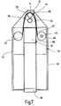
- FIG. 7shows an embodiment of a blood sugar measuring instrument in cross-section with a tape guide that can be moved backwards and forwards;
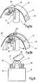
- FIG. 8 a to cshow a tape guide that can be moved between an instrument housing and an inner shell in a partial perspective diagram
- FIGS. 9 a and bshow an illustrative diagram of the lancing action through the test tape and the subsequent optical detection
- FIG. 10shows a spring-mounted finger cone in a very simplified section
- FIGS. 11 and 12show other embodiments with a pivoted lever mechanism to draw out a tape loop from a cassette in two different views;
- FIGS. 13 a, b, cshow embodiments of a platform for attaching several instrument components
- FIG. 14shows two instrument components for fitting onto a platform in conjunction with a positioning drive in a simplified illustrative view
- FIGS. 15 a, bshow the embodiment according to FIG. 14 in an instrument housing in two different operating positions.
- the blood sugar measuring instrument shown in FIG. 1comprises a housing 10 , a blood collection cone 12 attached thereto as a receiving element for a finger of a test person, an abutment 14 inside the housing which interacts with the blood collection cone 12 , a lancing unit 16 with a lancing member 18 for piercing the finger, a tape unit 20 containing a test tape 22 for applying the blood emerging from the finger puncture and a detection unit for examining the blood on the test tape 22 .
- the abutment 14can be moved between a release position and an operating position relative to the blood collection cone 12 .
- In the operating positionit is possible by contacting the body part to be punctured, to determine a reference position for a defined puncture depth whereas in the release position the blood can emerge unhindered from the generated skin opening and a free space is created for receiving a drop of blood on the test tape 22 .
- the lancing process and the blood applicationtake place at the same site in the area of the blood collection cone 12 so that the user does not have to carry out a movement to change the position and the measurement process can be carried out completely automatically.
- the abutment 14is formed by a front surface 26 facing towards the blood collection cone 12 of a front cap 30 of the lancing unit 16 which can be moved in the lancing axis 28 in the direction of the double arrow 29 .
- the front surface 26is provided with a piercing opening 32 through which the lancing member 18 can pierce in a linear lancing stroke (double arrow 33 ).
- the lancing unit 16has a lancing drive 34 which can be coupled to a lancing member 18 formed by a lancet.
- a plurality of lancets 18can be stored in a magazine 36 .
- the lancing unit 16In order to adjust the lancing stroke relative to the abutment 14 , the lancing unit 16 has an adjustment device 38 that can be operated from outside of the housing. As a further external operating element the lancing unit 16 has a trigger 40 which allows a manual triggering of the lancing stroke of the lancing drive 34 by the user.
- the tape unit 20comprises a cassette 43 in which the test tape 22 can be pulled from a supply spool 44 and reeled onto a take-up spool 48 by means of a tape advance drive 46 .
- the test tape 22has a plurality of tape sections 50 which are coated with dry chemicals that react with the blood fluid that is applied thereto resulting in an optically detectable color change that corresponds to the blood sugar concentration.
- a deflecting head 52is provided to form a tape loop that can be positioned in the area of the blood collection cone 12 .
- the said deflecting head with its convex guide surface 56can be moved in the direction of a double arrow 58 backwards and forwards relative to the exposed section of tape 50 between deflecting rollers 54 so that a drop of blood can be taken up onto the tape section 50 in the area of the blood collection cone 12 even when the constructional space is confined.
- the deflecting head 52is also equipped as a detection unit 24 with a reflection photometric measuring device 60 in order to carry out an optical detection measurement on the section of tape 50 that is loaded with blood.
- the blood collection cone 12increases the internal pressure in the pressed body part. This allows sufficient amounts of capillary blood to be already obtained with very small puncture depths and correspondingly less puncture pain.
- a ring lip 64 with a double conical taper towards an engagement opening 62 that is made of an elastomeric materialis provided for adaptation to different finger contours. This results in a ring-shaped lateral compression when it is pressure deformed by an engaging finger which results in a bulging of the finger tip towards the abutment 14 and towards the lancing member 18 .
- Such a finger coneis known from German patent application DE-A 100 26 172 for forming a dammed-up volume of blood in the finger tip in combination with a test strip system.
- receiving elements adapted to the anatomy of other parts of the bodyare also conceivable instead of the ring lip 64 .
- the housing 10 or the engagement opening 62can be formed over a large rigid cone which can be placed on the lower arm.
- the palm of the hand or earlobecan also be used as further alternative puncture sites.
- FIG. 2 ashows the abutment 14 in an operating position relative to the blood collection cone 12 where the end face 26 of the engagement opening 62 faces the inner side of the housing.
- the userpresses a finger 66 against the elastically deformable blood collection cone 12 until the finger pad 68 makes contact with the end face 26 .
- the lancet 18is then advanced and retracted by an exactly adjustable stroke travel through the piercing opening 32 to beyond the end face 26 ( FIG. 2 c ).
- the abutment 14 together with the lancet 18is then withdrawn away from the blood collection cone 12 into the release position in order to create a free space for blood to escape.
- a drop of blood 68 which has emergedcan be applied to the loop-shaped exposed section of tape 50 by an advancing motion of the deflecting head 52 . Afterwards the user can lift his finger 66 from the blood collection cone 12 . After the detection measurement has been carried out by the measuring device 60 , the result is displayed on a display that is not shown. Finally the used section of tape 50 is reeled on so that the instrument is again ready for measurement.
- the lancing unit 16 and the tape unit 20can be alternately brought into an operating position relative to the blood collection cone 12 by means of a positioning device 70 .
- the units 16 and 20can be moved in a fixed position 72 relative to one another as an assembly in a straight line in a linear guide 74 by means of a rigid support structure 72 .
- the test tape 22can be activated for blood application by means of the deflecting or measuring head 24 that tapers at an acute angle.
- the support structure 72 for the lancing and tape unitis guided on a U-shaped path curve.
- the support structure 72is connected via four pivot arms 76 with rigid hinged joints on the housing.
- the lancing unit 16is positioned opposite to the blood collection cone 12 .
- the middle pivot position according to FIG. 4 bthe blood collection cone 12 is released for blood to escape.
- the tape unit 20is positioned in the pivot position according to FIG. 4 c in which a loop-shaped section of tape 50 engages in the area of the blood collection cone 12 .
- the lancing unit 16 and the tape unit 20are rigidly arranged in the instrument whereas the abutment 14 is formed by a movable tape guide 90 for the test tape 22 whose movement is limited in the lancing direction.
- the tape guide 90has a support element 94 supported in the head piece 92 of the lancing unit 16 which can be displaced towards and away from the blood collection cone 12 by turning a cam disk 96 .
- the supporting element 94In the initial state before the lancing movement, the supporting element 94 is in the upper position on a cam of the cam disk 96 shown in FIG. 7 .
- the usercompresses the blood collection cone 12 slightly until his finger touches the abutment 14 .
- the support element 94is subsequently lowered slightly by rotating the cam disk 96 into an intermediate position between the cams.
- a tape section 50 to be loadedis positioned on the support element 94 by the feed drive 46 and kept in abutment.
- the cam disk 96is then rotated further until the support element 94 again rests on a cam and the lifted section of tape 50 collects the drop of blood on the finger.
- a shell-shaped guide frame 100can also be used as a tape guide 90 ( FIG. 8 b ) which is arranged between an outer housing shell 102 ( FIG. 8 a ) and an inner housing shell 104 ( FIG. 8 c ) and has a limited amount of movement in the lancing direction.
- the outer shell 102carries the blood collection cone 12
- a guide shaft 106 for the lancets and an optical detection unit 24are attached to the inner shell 104 .
- the guide frame 100that arches in a curved manner towards the blood collection cone 12 is only movable at one end 110 by a predetermined swinging stroke whereas the other end of the frame 108 is located in a fixed position on the tape cassette 42 .
- the lancing processcan take place directly through a thin support foil 114 of the test tape 22 where it is expedient that a pilot hole 116 positioned in the lancing axis prevents unintentional damage to the lancet tip 118 .
- Sections of the support foil 114are coated with a test field 118 which, after the lancing process, is advanced with the tape into the blood collection and measuring position shown in FIG. 9 b by suitable control devices such as a light barrier or a mechanical aperture mask guide.
- the optical detection unit 24 used for a contactless detectioncomprises a measuring circuit board 120 with three light sources (LEDs 122 ) and a photosensor 124 as well as collection optics (lens 126 ).
- the LEDs 122are arranged in a row and correspondingly generate a row of three light spots 128 in the direction of tape transport by means of the lens 126 .
- the said light spotsare located on the test field 118 in the area of the lancing axis above the transparent support foil 114 .
- the LEDs 122are actuated successively.
- the middle LEDis used for the actual detection measurement whereas the two outer LEDs enable a control of the dosage.
- An erroneous dosingis detected when there is an asymmetric signal distribution.
- the test field 118contains dry chemicals that respond to the analyte (glucose) in the applied blood fluid and result in a change in the reflected light radiation.
- FIG. 10shows a blood collection cone 12 which is supported by spring elements 130 relative to the housing 10 in such a manner that a movement is possible relative to the test tape 22 or its guide 90 under the pressure of the finger 66 .
- the spring elements 130can be designed to be similar to a corrugated bellows and should become harder in a non-linear manner with increasing deformation.
- the abutment 14is formed by the stretched support foil 114 and can be brought into the operating or release position relative to the receiving element by a backwards and forwards movement of the blood collection cone 12 .
- the tape cassette 42has a clearance 132 at a suitable position in which a deflecting roller 134 engages when the cassette is inserted.
- This roller 134is supported at the free end of a pivoted lever 136 which can execute a reciprocating swivel movement in the direction of the arrow 138 . If, after the skin has been punctured, the lancing unit 16 or at least the front part thereof is moved back (arrow 29 ), the roller 134 can swing out and thus pull a tape loop 140 out of the cassette 42 and move it to the site of blood collection.
- the distance over which the lancing device has to be movedis essentially defined by the diameter of the roller 134 which can be relatively small (e.g. 3 mm).
- Two additional guide rollers 142are provided to prevent the test tape 22 from exerting adverse forces for example on a seal of the cassette 42 during this movement and, on the other hand, to prevent it rubbing against other instrument structures.
- the lever 136 with the roller 134pulls out fresh tape 22 from the supply spool which is not driven but only braked. This ensures that after the swivel movement a test field 50 provided with detection chemicals lies under the cone 12 .
- the roller 134On its swivel movement the roller 134 is specifically guided in a curve from below to the punctured skin so that it (viewed from the cassette 42 ) arrives at the finger across from the puncture site.
- the tape loop 140is not only quasi rolled out onto the skin but is gently moved from below to the site where blood escapes. This is carried out by the motor force of a pivot drive 144 .
- the tape 22is reeled in from the take-up roller to such an extent that the site wetted with blood comes to rest in front of the detection unit 24 .
- the tape 22With a suitable arrangement of cone 12 , cassette 42 and pivot point of the lever 136 , the tape 22 nestles at this moment over the tip of the cassette which positions it precisely in front of the optics of the detection unit 24 .
- the roller 134is hauled in on its lever 136 which is now only spring-loaded like a pulley.
- the spring loadingin this case ensures that the tape never becomes slack.
- a special advantageis that a clean tape movement occurs without contaminating instrument structures with blood even in those cases in which the body part to be lanced cannot be exposed very far into the instrument.
- a preferred embodiment according to FIG. 12consists in the fact that the roller 134 is clipped into the recess 132 of the cassette 42 .
- the rolleris automatically attached to the bearing pin 146 on the lever arm 136 ′ without the user having to take care of it.
- the rolleris again clipped by a motor drive into the arrestment so that when the cassette 42 is removed from the housing 10 , it can be hygienically disposed as a component of the cassette.
- the roller 134In order that the roller 134 cannot become detached from the pin 146 by the force of gravity or knocks, it has to be guided axially. This can be achieved by guide ribs (not shown) that run along the path of movement of the roller 134 which restrict the freedom of movement in the axial direction and optionally additionally act as an auxiliary guide for the tape.
- the lever 136is in two parts ( 136 ′ and 136 ′′). One lever arm 136 ′ with the bearing pin 146 is driven in a pivoted manner whereas the second lever arm 136 ′′ is pressed towards the cassette under a slight spring load but is stopped there at a solid stop. If the first lever 136 ′ with the roller 134 now pivots away from the cassette 42 , it takes along the second lever 136 ′′ with the protruding end of the bearing pin 146 which thus provides an axial stop for the roller 134 .
- the two levers 136 ′, 136 ′′are pivoted on both sides of the lancing unit 16 and the bearings are in alignment.
- a special embodimentallows a movement of the bearing axes towards the finger cone 12 against the restoring force of the springs 148 .
- the roller 134is exactly under the cone 12 but does not yet touch the finger pad.
- the test field on the test tape 22wraps around at least the upper hemisphere of the roller 134 . Once this state has been reached, the lancing unit 16 moves upwards and in doing so buts against the spring-mounted double lever 136 whereupon it is taken along by it.
- Another embodiment that is not shownuses a simple tongue made of metal sheet instead of a roller 134 which draws out the tape 22 in its (rigid) longitudinal direction but bears it resiliently against the skin in its transverse direction in which it is flexible. It is also conceivable that the cassette 42 , the detection unit 24 and the lancing unit 136 do not lie in one plane. The flexibility of the tape 22 would then allow it to move towards a lancing site at an angle to the cassette plane with a lateral excursion at right angles to the tape loop.
- a loop of tapecan be transported to the site of blood application by a detection unit designed as a deflecting head 56 as described above for FIG. 1 .
- a detection unitdesigned as a deflecting head 56 as described above for FIG. 1 .
- This clampingcan be achieved by means of a fork which is arranged in the traverse path of the deflecting head and is taken along to the site of blood application by the deflecting head against a spring load. In this process the deflecting head engages between the arms of the fork such that the test tape is firmly and immovably clamped.
- the pulling out of a tape loopcan also be used to advantage when not only the test tape together with the detection unit are transported to the site of blood application but also when additionally the lancing unit is moved with them in close proximity.
- the lancingoccurs through a section of support tape located between the test fields.
- the bloodis taken up by a forwards movement and after another retraction the test field is spooled over the detection unit.
- a separate lateral movement of a section of tape in the form of a tape loopis helpful in addition to the mere rewinding of the tape from the supply spool to the take-up spool.
- a movable platform 150is envisaged as a core piece on which the instrument components required to carry out blood collection and analysis or other instrument functions can be attached.
- Any possible embodiment of a support structure for components that are to be attached theretocan come into consideration as a platform.
- FIG. 13 aillustrates a platform 150 with clamping devices 152 mounted thereon
- FIG. 13 bshows a base 150 with assembly plates 154 mounted thereon
- FIG. 13 cshows a base 150 in the form of a grid construction with variable attachment points 156 .
- the platform 150is movable within the housing 10 in order to position the components attached thereto for obtaining blood, blood collection or other functions.
- the target positionis defined in particular with reference to the finger receiving element 12 of the housing 10 .
- the platform 150should if possible be moved such that the components attached thereto can be moved to their corresponding target positions in a distal direction.
- An arc-shaped (semi circular) movementis preferably selected for this. If there are more than two components, the arc-shaped movement can be executed successively for a corresponding number of times.
- the width of the arc of the individual movementscan also be adapted to the required dimensions of the components that are used i.e. arcs of different width are executed.
- the movable platform 150can either be adjusted as a unit or the individual attachment points of the attached components can be adjusted.
- the direction of movement of the adjustment motionpreferably runs axially to the receiving element 12 so that the height of all the units or of the individual components can be adjusted.
- the adjustmentis either carried out manually e.g. during assembly or automatically during the measurement operation. An individual adaptation to the respective user is also conceivable.
- a simple electromechanical positioning device 158can move the platform 150 to position the lancing unit and test means unit 20 ′ attached thereto. In this case the movement occurs by rotating a pin 160 on disk 162 in a slotted link 164 . It is for example also possible to transfer the movement by translating the rotational movement of a lever or directly by rotating a gear wheel in a slotted link on the movable platform 150 (not shown). In this connection it is important that the respective end positions are stable.
- Attachment areas 164 for the components 16 , 20 ′ to be movedare provided on the movable platform 150 . It is obvious that any suitable attachment elements meeting the requirements of the respective instrument components can be used and do not therefore have to be described in more detail. What is specially shown is the modular platform combination of individual components 16 , 20 ′ which are already well-known and commercialized under the trademark Accu-Chek® Compact blood glucose monitoring system.
- the lancing aid 16enables a lancing movement of a lancet to be triggered while the module 20 ′ comprises a drum magazine 166 with an output and push rod for automatic blood collection onto individual test strips and measuring optics as a detection unit for blood glucose analysis.
- FIG. 15shows the assembled instrument.
- the end of the lancing aid 16protrudes from the housing ( FIG. 15 a ).
- the button 168can still be operated by the user to tension the lancing aid and lancets can be changed as usual when required by removing the lower cap 170 .
- the wheel 162 located behind the movable platform 150rotates and moves the lancing aid 16 in an arc shape by means of the pin 160 and the slotted link 164 into the lancing position above the receiving member 12 ( FIG. 15 b ). Then the lancing operation can be triggered either manually by the user or by an automated function.
- the movable platform 150 with the components 16 , 20 ′ attached theretocan be moved back into the initial position by rotating the positioning device 158 in the opposite direction.
- the component 20 ′ with the drum 166is now located above the receiving element 12 .
- a test stripcan be pushed out of the drum 166 which takes up the sample volume by means of a capillary and transports it to a test field.
- the measuring optics located below the drumcan then carry out the measurement. Subsequently the used test strips are pulled back into the drum for disposal.
- the handlingis considerably simplified for the user and the entire measurement process can take place in a substantially automated manner.
- the term “substantially”is utilized herein to represent the inherent degree of uncertainty that may be attributed to any quantitative comparison, value, measurement, or other representation.
- the term “substantially”is also utilized herein to represent the degree by which a quantitative representation may vary from a stated reference without resulting in a change in the basic function of the subject matter at issue.
Landscapes
- Health & Medical Sciences (AREA)
- Life Sciences & Earth Sciences (AREA)
- Physics & Mathematics (AREA)
- Engineering & Computer Science (AREA)
- Biomedical Technology (AREA)
- General Health & Medical Sciences (AREA)
- Pathology (AREA)
- Biophysics (AREA)
- Molecular Biology (AREA)
- Public Health (AREA)
- Veterinary Medicine (AREA)
- Animal Behavior & Ethology (AREA)
- Surgery (AREA)
- Medical Informatics (AREA)
- Heart & Thoracic Surgery (AREA)
- Hematology (AREA)
- Chemical & Material Sciences (AREA)
- Dermatology (AREA)
- Optics & Photonics (AREA)
- General Physics & Mathematics (AREA)
- Biochemistry (AREA)
- Analytical Chemistry (AREA)
- Immunology (AREA)
- Urology & Nephrology (AREA)
- Food Science & Technology (AREA)
- Emergency Medicine (AREA)
- Medicinal Chemistry (AREA)
- Pain & Pain Management (AREA)
- Geometry (AREA)
- Measurement Of The Respiration, Hearing Ability, Form, And Blood Characteristics Of Living Organisms (AREA)
- Investigating Or Analysing Biological Materials (AREA)
- Sampling And Sample Adjustment (AREA)
- Automatic Analysis And Handling Materials Therefor (AREA)
Abstract
Description
- the support structure can be moved into the respective end position of the instrument components by means of a positioning device and preferably on a curved path;
- the support structure consists of a platform provided with attachment elements for the instrument components;
- the support structure has clamping, screwing or locking members to locate the instrument components preferably in a detachable manner;
- the support structure has attachment points for the instrument components that are preferably arranged in a grid shape;
- the unit for the test means has a magazine for processing and in particular for the provision and disposal of a plurality of test strips.
Claims (49)
Applications Claiming Priority (4)
| Application Number | Priority Date | Filing Date | Title |
|---|---|---|---|
| DE10332488ADE10332488A1 (en) | 2003-07-16 | 2003-07-16 | Analyzer and analysis method for body fluids |
| DE10332488.7 | 2003-07-16 | ||
| DE10332488 | 2003-07-16 | ||
| PCT/EP2004/007785WO2005006985A2 (en) | 2003-07-16 | 2004-07-14 | Analysis apparatus and analysis method for body fluids |
Related Parent Applications (1)
| Application Number | Title | Priority Date | Filing Date |
|---|---|---|---|
| PCT/EP2004/007785ContinuationWO2005006985A2 (en) | 2003-07-16 | 2004-07-14 | Analysis apparatus and analysis method for body fluids |
Publications (2)
| Publication Number | Publication Date |
|---|---|
| US20060173380A1 US20060173380A1 (en) | 2006-08-03 |
| US8684949B2true US8684949B2 (en) | 2014-04-01 |
Family
ID=34071728
Family Applications (1)
| Application Number | Title | Priority Date | Filing Date |
|---|---|---|---|
| US11/333,666Expired - Fee RelatedUS8684949B2 (en) | 2003-07-16 | 2006-01-17 | Analysis apparatus and analysis method for body fluids |
Country Status (7)
| Country | Link |
|---|---|
| US (1) | US8684949B2 (en) |
| EP (1) | EP1643909B1 (en) |
| JP (1) | JP4578472B2 (en) |
| CN (1) | CN1822792B (en) |
| CA (1) | CA2532441C (en) |
| DE (1) | DE10332488A1 (en) |
| WO (1) | WO2005006985A2 (en) |
Cited By (3)
| Publication number | Priority date | Publication date | Assignee | Title |
|---|---|---|---|---|
| US20160025638A1 (en)* | 2013-03-12 | 2016-01-28 | Bayer Healthcare Llc | Test strip meter with a mechanism for pushing the test strip against an optical reader |
| US9335333B2 (en) | 2011-09-16 | 2016-05-10 | Roche Diabetes Care, Inc. | Test tape cassette and analytical test tape therefor |
| US11399755B2 (en) | 2016-08-24 | 2022-08-02 | Becton, Dickinson And Company | Device for obtaining a blood sample |
Families Citing this family (110)
| Publication number | Priority date | Publication date | Assignee | Title |
|---|---|---|---|---|
| US6036924A (en) | 1997-12-04 | 2000-03-14 | Hewlett-Packard Company | Cassette of lancet cartridges for sampling blood |
| US6391005B1 (en) | 1998-03-30 | 2002-05-21 | Agilent Technologies, Inc. | Apparatus and method for penetration with shaft having a sensor for sensing penetration depth |
| DE10057832C1 (en) | 2000-11-21 | 2002-02-21 | Hartmann Paul Ag | Blood analysis device has syringe mounted in casing, annular mounting carrying needles mounted behind test strip and being swiveled so that needle can be pushed through strip and aperture in casing to take blood sample |
| US8641644B2 (en) | 2000-11-21 | 2014-02-04 | Sanofi-Aventis Deutschland Gmbh | Blood testing apparatus having a rotatable cartridge with multiple lancing elements and testing means |
| AU2002344825A1 (en) | 2001-06-12 | 2002-12-23 | Pelikan Technologies, Inc. | Method and apparatus for improving success rate of blood yield from a fingerstick |
| US9427532B2 (en) | 2001-06-12 | 2016-08-30 | Sanofi-Aventis Deutschland Gmbh | Tissue penetration device |
| EP1395185B1 (en) | 2001-06-12 | 2010-10-27 | Pelikan Technologies Inc. | Electric lancet actuator |
| JP4209767B2 (en) | 2001-06-12 | 2009-01-14 | ペリカン テクノロジーズ インコーポレイテッド | Self-optimized cutting instrument with adaptive means for temporary changes in skin properties |
| US9226699B2 (en) | 2002-04-19 | 2016-01-05 | Sanofi-Aventis Deutschland Gmbh | Body fluid sampling module with a continuous compression tissue interface surface |
| US9795747B2 (en) | 2010-06-02 | 2017-10-24 | Sanofi-Aventis Deutschland Gmbh | Methods and apparatus for lancet actuation |
| US7749174B2 (en) | 2001-06-12 | 2010-07-06 | Pelikan Technologies, Inc. | Method and apparatus for lancet launching device intergrated onto a blood-sampling cartridge |
| US7041068B2 (en) | 2001-06-12 | 2006-05-09 | Pelikan Technologies, Inc. | Sampling module device and method |
| US7981056B2 (en) | 2002-04-19 | 2011-07-19 | Pelikan Technologies, Inc. | Methods and apparatus for lancet actuation |
| US8337419B2 (en) | 2002-04-19 | 2012-12-25 | Sanofi-Aventis Deutschland Gmbh | Tissue penetration device |
| JP4272051B2 (en) | 2001-06-12 | 2009-06-03 | ペリカン テクノロジーズ インコーポレイテッド | Blood sampling apparatus and method |
| WO2002101359A2 (en) | 2001-06-12 | 2002-12-19 | Pelikan Technologies, Inc. | Integrated blood sampling analysis system with multi-use sampling module |
| US7344507B2 (en) | 2002-04-19 | 2008-03-18 | Pelikan Technologies, Inc. | Method and apparatus for lancet actuation |
| US7344894B2 (en) | 2001-10-16 | 2008-03-18 | Agilent Technologies, Inc. | Thermal regulation of fluidic samples within a diagnostic cartridge |
| US7708701B2 (en) | 2002-04-19 | 2010-05-04 | Pelikan Technologies, Inc. | Method and apparatus for a multi-use body fluid sampling device |
| US7232451B2 (en) | 2002-04-19 | 2007-06-19 | Pelikan Technologies, Inc. | Method and apparatus for penetrating tissue |
| US9795334B2 (en) | 2002-04-19 | 2017-10-24 | Sanofi-Aventis Deutschland Gmbh | Method and apparatus for penetrating tissue |
| US9248267B2 (en) | 2002-04-19 | 2016-02-02 | Sanofi-Aventis Deustchland Gmbh | Tissue penetration device |
| US9314194B2 (en) | 2002-04-19 | 2016-04-19 | Sanofi-Aventis Deutschland Gmbh | Tissue penetration device |
| US8579831B2 (en) | 2002-04-19 | 2013-11-12 | Sanofi-Aventis Deutschland Gmbh | Method and apparatus for penetrating tissue |
| US7297122B2 (en) | 2002-04-19 | 2007-11-20 | Pelikan Technologies, Inc. | Method and apparatus for penetrating tissue |
| US8784335B2 (en) | 2002-04-19 | 2014-07-22 | Sanofi-Aventis Deutschland Gmbh | Body fluid sampling device with a capacitive sensor |
| US7331931B2 (en) | 2002-04-19 | 2008-02-19 | Pelikan Technologies, Inc. | Method and apparatus for penetrating tissue |
| US7481776B2 (en) | 2002-04-19 | 2009-01-27 | Pelikan Technologies, Inc. | Method and apparatus for penetrating tissue |
| US7648468B2 (en) | 2002-04-19 | 2010-01-19 | Pelikon Technologies, Inc. | Method and apparatus for penetrating tissue |
| US7976476B2 (en) | 2002-04-19 | 2011-07-12 | Pelikan Technologies, Inc. | Device and method for variable speed lancet |
| US7491178B2 (en) | 2002-04-19 | 2009-02-17 | Pelikan Technologies, Inc. | Method and apparatus for penetrating tissue |
| US7141058B2 (en) | 2002-04-19 | 2006-11-28 | Pelikan Technologies, Inc. | Method and apparatus for a body fluid sampling device using illumination |
| US8267870B2 (en) | 2002-04-19 | 2012-09-18 | Sanofi-Aventis Deutschland Gmbh | Method and apparatus for body fluid sampling with hybrid actuation |
| US7582099B2 (en) | 2002-04-19 | 2009-09-01 | Pelikan Technologies, Inc | Method and apparatus for penetrating tissue |
| US7674232B2 (en) | 2002-04-19 | 2010-03-09 | Pelikan Technologies, Inc. | Method and apparatus for penetrating tissue |
| US7892183B2 (en) | 2002-04-19 | 2011-02-22 | Pelikan Technologies, Inc. | Method and apparatus for body fluid sampling and analyte sensing |
| US7291117B2 (en) | 2002-04-19 | 2007-11-06 | Pelikan Technologies, Inc. | Method and apparatus for penetrating tissue |
| US8702624B2 (en) | 2006-09-29 | 2014-04-22 | Sanofi-Aventis Deutschland Gmbh | Analyte measurement device with a single shot actuator |
| US7909778B2 (en) | 2002-04-19 | 2011-03-22 | Pelikan Technologies, Inc. | Method and apparatus for penetrating tissue |
| US7524293B2 (en) | 2002-04-19 | 2009-04-28 | Pelikan Technologies, Inc. | Method and apparatus for penetrating tissue |
| US7371247B2 (en) | 2002-04-19 | 2008-05-13 | Pelikan Technologies, Inc | Method and apparatus for penetrating tissue |
| US7547287B2 (en) | 2002-04-19 | 2009-06-16 | Pelikan Technologies, Inc. | Method and apparatus for penetrating tissue |
| US7563232B2 (en) | 2002-04-19 | 2009-07-21 | Pelikan Technologies, Inc. | Method and apparatus for penetrating tissue |
| US7410468B2 (en) | 2002-04-19 | 2008-08-12 | Pelikan Technologies, Inc. | Method and apparatus for penetrating tissue |
| US7229458B2 (en) | 2002-04-19 | 2007-06-12 | Pelikan Technologies, Inc. | Method and apparatus for penetrating tissue |
| US7374544B2 (en) | 2002-04-19 | 2008-05-20 | Pelikan Technologies, Inc. | Method and apparatus for penetrating tissue |
| US7717863B2 (en) | 2002-04-19 | 2010-05-18 | Pelikan Technologies, Inc. | Method and apparatus for penetrating tissue |
| US8221334B2 (en) | 2002-04-19 | 2012-07-17 | Sanofi-Aventis Deutschland Gmbh | Method and apparatus for penetrating tissue |
| US7901362B2 (en) | 2002-04-19 | 2011-03-08 | Pelikan Technologies, Inc. | Method and apparatus for penetrating tissue |
| US8574895B2 (en) | 2002-12-30 | 2013-11-05 | Sanofi-Aventis Deutschland Gmbh | Method and apparatus using optical techniques to measure analyte levels |
| US7850621B2 (en) | 2003-06-06 | 2010-12-14 | Pelikan Technologies, Inc. | Method and apparatus for body fluid sampling and analyte sensing |
| WO2006001797A1 (en) | 2004-06-14 | 2006-01-05 | Pelikan Technologies, Inc. | Low pain penetrating |
| EP1635700B1 (en) | 2003-06-13 | 2016-03-09 | Sanofi-Aventis Deutschland GmbH | Apparatus for a point of care device |
| US8282576B2 (en) | 2003-09-29 | 2012-10-09 | Sanofi-Aventis Deutschland Gmbh | Method and apparatus for an improved sample capture device |
| EP1680014A4 (en) | 2003-10-14 | 2009-01-21 | Pelikan Technologies Inc | METHOD AND DEVICE FOR A VARIABLE USER INTERFACE |
| US7822454B1 (en) | 2005-01-03 | 2010-10-26 | Pelikan Technologies, Inc. | Fluid sampling device with improved analyte detecting member configuration |
| US8668656B2 (en) | 2003-12-31 | 2014-03-11 | Sanofi-Aventis Deutschland Gmbh | Method and apparatus for improving fluidic flow and sample capture |
| WO2006011062A2 (en) | 2004-05-20 | 2006-02-02 | Albatros Technologies Gmbh & Co. Kg | Printable hydrogel for biosensors |
| DE102004024970A1 (en)* | 2004-05-21 | 2005-12-08 | Roche Diagnostics Gmbh | Device and method for positioning a body part |
| WO2005120365A1 (en) | 2004-06-03 | 2005-12-22 | Pelikan Technologies, Inc. | Method and apparatus for a fluid sampling device |
| US8652831B2 (en) | 2004-12-30 | 2014-02-18 | Sanofi-Aventis Deutschland Gmbh | Method and apparatus for analyte measurement test time |
| DE102005013685A1 (en)* | 2005-03-18 | 2006-09-28 | Roche Diagnostics Gmbh | Tape magazine for a hand-held device for examining a body fluid, as well as a hand-held device |
| EP1743577A1 (en)* | 2005-06-23 | 2007-01-17 | Roche Diagnostics GmbH | Hand-held apparatus for the analysis of bodily fluids |
| FI121698B (en) | 2005-07-19 | 2011-03-15 | Ihq Innovation Headquarters Oy | Health monitoring device and sensor cassette for the health monitoring device |
| EP1801584A1 (en)* | 2005-12-24 | 2007-06-27 | F.Hoffmann-La Roche Ag | Analysis system for body fluids |
| ES2401692T3 (en) | 2006-03-14 | 2013-04-23 | F. Hoffmann-La Roche Ag | Method for preparing a multilayer analytical element |
| EP1873521B1 (en)* | 2006-06-27 | 2011-09-21 | F. Hoffmann-La Roche AG | Diagnostic test band cassette |
| JP2008007004A (en)* | 2006-06-30 | 2008-01-17 | Fuji Heavy Ind Ltd | Control device for hybrid vehicle |
| KR20090031763A (en)* | 2006-07-06 | 2009-03-27 | 라피딕스 리미티드. | Integrated blood sampling and testing device and method |
| EP1878379B1 (en)* | 2006-07-11 | 2019-10-16 | F. Hoffmann-La Roche AG | Test tape system, in particular for blood sugar analysis |
| EP1881322B8 (en)* | 2006-07-18 | 2011-09-28 | Roche Diagnostics GmbH | Space-optimised portable measuring system |
| ES2421781T3 (en) | 2006-09-04 | 2013-09-05 | Hoffmann La Roche | Puncture system to extract a body fluid |
| EP1917909A1 (en) | 2006-10-12 | 2008-05-07 | Roche Diagnostics GmbH | Sampling system and method to obtain liquid samples |
| ATE462135T1 (en)* | 2007-02-03 | 2010-04-15 | Hoffmann La Roche | DIAGNOSTIC TEST TAPE UNIT, IN PARTICULAR TEST TAPE CASSETTE |
| EP2363062B1 (en) | 2007-04-21 | 2017-11-22 | Roche Diabetes Care GmbH | Analytical system for detecting an analyte in a body fluid |
| EP1988394A1 (en) | 2007-05-04 | 2008-11-05 | F. Hoffmann-La Roche AG | Measuring system with distributed functions |
| ES2354912T3 (en) | 2007-05-16 | 2011-03-21 | Roche Diagnostics Gmbh | PUNCTURE SYSTEM |
| WO2008154710A1 (en)* | 2007-06-18 | 2008-12-24 | União Brasileira De Educacão E Assistência | Blood collector device and blood analysis process |
| EP2011630A1 (en) | 2007-07-03 | 2009-01-07 | F. Hoffmann-La Roche AG | Method for manufacturing an analytical element |
| EP2039293A1 (en) | 2007-09-19 | 2009-03-25 | F. Hoffman-la Roche AG | Combination drive for a sample extraction system for obtaining a liquid sample |
| DE502007005368D1 (en) | 2007-10-29 | 2010-11-25 | Roche Diagnostics Gmbh | Method of making tape with diagnostic aids |
| WO2009081405A2 (en)* | 2007-12-25 | 2009-07-02 | Rapidx Ltd. | Devices and methods for reduced-pain blood sampling |
| AU2009219678A1 (en)* | 2008-02-27 | 2009-09-03 | Mon4D Ltd. | Device, system and method for modular analyte monitoring |
| EP2265324B1 (en) | 2008-04-11 | 2015-01-28 | Sanofi-Aventis Deutschland GmbH | Integrated analyte measurement system |
| EP2138842A1 (en)* | 2008-06-25 | 2009-12-30 | F. Hoffmann-Roche AG | Analysis handheld device for investigating a bodily fluid and control method for same |
| EP2151686A1 (en) | 2008-08-04 | 2010-02-10 | Roche Diagnostics GmbH | Analysis system with encryption detection |
| US8956308B2 (en)* | 2008-09-29 | 2015-02-17 | Bayer Healthcare Llc | Integrated-testing system |
| EP2208995A1 (en) | 2009-01-15 | 2010-07-21 | Roche Diagnostics GmbH | Folded carrier belt with consumption elements |
| EP2208459A1 (en)* | 2009-01-16 | 2010-07-21 | F. Hoffmann-Roche AG | System and method for analysing a body fluid |
| US20100198107A1 (en)* | 2009-01-30 | 2010-08-05 | Roche Diagnostics Operations, Inc. | Integrated blood glucose meter and lancing device |
| US9375169B2 (en) | 2009-01-30 | 2016-06-28 | Sanofi-Aventis Deutschland Gmbh | Cam drive for managing disposable penetrating member actions with a single motor and motor and control system |
| EP2236082B1 (en) | 2009-04-03 | 2011-11-30 | Roche Diagnostics GmbH | Device to obtain and analyse a blood sample |
| PL2243711T3 (en) | 2009-04-22 | 2012-12-31 | Hoffmann La Roche | Manufacturing tape products with diagnostic item |
| PL2322095T3 (en) | 2009-11-17 | 2018-10-31 | Beurer Gmbh | Measuring device for blood parameters |
| PL2503938T3 (en)* | 2009-11-24 | 2014-03-31 | Hoffmann La Roche | Belt magazine with backing block and integrated belt release |
| CN101846686A (en)* | 2009-12-10 | 2010-09-29 | 金薇 | Automatic correction and continuous testing magazine-type glucometer and matched test strip |
| US8965476B2 (en) | 2010-04-16 | 2015-02-24 | Sanofi-Aventis Deutschland Gmbh | Tissue penetration device |
| EP2417910B1 (en)* | 2010-08-11 | 2013-06-26 | Roche Diagnostics GmbH | Analytical test unit and test system |
| DE102011005254B4 (en)* | 2011-03-08 | 2013-04-11 | Bst Bio Sensor Technologie Gmbh | Apparatus and method for assaying sample liquids |
| US9357961B2 (en)* | 2013-02-22 | 2016-06-07 | Thuban, Inc. | Device for enabling patient self testing and treatment self- administration and system using the device for managing the patient's health care |
| CN103149363A (en)* | 2013-03-06 | 2013-06-12 | 江苏岱洛医疗科技有限公司 | Integrated glucose meter |
| DE102014201076B3 (en)* | 2014-01-22 | 2015-03-05 | Bruker Biospin Ag | Transport container for an NMR MAS rotor |
| CN103829953B (en)* | 2014-03-06 | 2017-01-11 | 上海移宇科技股份有限公司 | One-step type integrated blood glucose meter |
| WO2016025709A1 (en)* | 2014-08-13 | 2016-02-18 | Oregon Health & Science University | Dried blood spot collection device |
| CN104546021B (en)* | 2015-01-13 | 2017-08-25 | 何宏 | Clinical laboratory's humor collecting feeding device for inspection |
| US10136848B2 (en)* | 2016-05-20 | 2018-11-27 | Winnoz Technology, Inc. | Device and system of blood collection, and method thereof |
| CN106405134B (en)* | 2016-08-26 | 2018-01-26 | 山丹县天马科技有限责任公司 | A blood cell analyzer |
| DE102017212192B3 (en)* | 2017-07-17 | 2018-10-18 | Bruker Biospin Ag | Transport device for an NMR MAS rotor into a probe head ("MAS Shuttle") |
| EP3477287A1 (en)* | 2017-10-26 | 2019-05-01 | Roche Diabetes Care GmbH | Analyte measuring system and method |
| US11707297B2 (en) | 2019-08-20 | 2023-07-25 | Ascensia Diabetes Care Holdings Ag | Continuous analyte monitor inserter apparatus and methods |
Citations (23)
| Publication number | Priority date | Publication date | Assignee | Title |
|---|---|---|---|---|
| US4577630A (en)* | 1984-02-14 | 1986-03-25 | Becton, Dickinson And Co. | Reusable breach loading target pressure activated lancet firing device |
| US5096828A (en)* | 1987-12-25 | 1992-03-17 | Fuji Photo Film Co., Ltd. | Biochemical analysis method |
| US5686829A (en)* | 1994-06-03 | 1997-11-11 | Metrohm Ag | Voltammetric method and apparatus |
| US5741288A (en)* | 1996-06-27 | 1998-04-21 | Chemtrak, Inc. | Re-armable single-user safety finger stick device having reset for multiple use by a single patient |
| US6036924A (en) | 1997-12-04 | 2000-03-14 | Hewlett-Packard Company | Cassette of lancet cartridges for sampling blood |
| JP2000217804A (en) | 1999-01-29 | 2000-08-08 | Kdk Corp | Lancet integrated measuring device |
| US6306152B1 (en)* | 1999-03-08 | 2001-10-23 | Agilent Technologies, Inc. | Lancet device with skin movement control and ballistic preload |
| US20020052618A1 (en)* | 2000-10-31 | 2002-05-02 | Hans-Peter Haar | Analytical device with integrated lancet |
| EP1238632A1 (en) | 1999-12-13 | 2002-09-11 | ARKRAY, Inc. | Body fluid measuring apparatus with lancet and lancet holder used for the measuring apparatus |
| WO2002078533A2 (en) | 2001-03-29 | 2002-10-10 | Inverness Medical Limited | Integrated sample testing meter |
| US20020177761A1 (en)* | 2001-04-26 | 2002-11-28 | Phoenix Bioscience | Integrated lancing and analytic device |
| US20020188224A1 (en)* | 2001-06-08 | 2002-12-12 | Roe Jeffrey N. | Test media cassette for bodily fluid testing device |
| US20030109777A1 (en)* | 2001-12-07 | 2003-06-12 | Kloepfer Hans G. | Consolidated body fluid testing device and method |
| US6589260B1 (en)* | 2000-05-26 | 2003-07-08 | Roche Diagnostics Corporation | System for withdrawing body fluid |
| US20030144608A1 (en)* | 2001-01-19 | 2003-07-31 | Shinichi Kojima | Lancet-integrated sensor, measurer for lancet-integrated sensor, and catridge |
| US20030211619A1 (en)* | 2002-05-09 | 2003-11-13 | Lorin Olson | Continuous strip of fluid sampling and testing devices and methods of making, packaging and using the same |
| EP1424040A1 (en) | 2002-11-26 | 2004-06-02 | Roche Diagnostics GmbH | Body fluid testing device |
| US20040127818A1 (en)* | 2002-12-27 | 2004-07-01 | Roe Steven N. | Precision depth control lancing tip |
| US20040225312A1 (en)* | 2003-05-09 | 2004-11-11 | Phoenix Bioscience | Linearly lancing integrated pivot disposable |
| US20040249406A1 (en)* | 2003-03-20 | 2004-12-09 | Griffin Carl E. | Lancing device with decoupled lancet |
| US6929650B2 (en)* | 2001-01-12 | 2005-08-16 | Arkray, Inc. | Lancing device |
| US20050201897A1 (en) | 2002-11-26 | 2005-09-15 | Volker Zimmer | Body fluid testing device |
| US20050232815A1 (en) | 2002-12-23 | 2005-10-20 | Werner Ruhl | Body fluid testing device |
- 2003
- 2003-07-16DEDE10332488Apatent/DE10332488A1/ennot_activeWithdrawn
- 2004
- 2004-07-14WOPCT/EP2004/007785patent/WO2005006985A2/enactiveApplication Filing
- 2004-07-14CNCN2004800204249Apatent/CN1822792B/ennot_activeExpired - Fee Related
- 2004-07-14JPJP2006519868Apatent/JP4578472B2/ennot_activeExpired - Fee Related
- 2004-07-14EPEP04763213.8Apatent/EP1643909B1/ennot_activeExpired - Lifetime
- 2004-07-14CACA2532441Apatent/CA2532441C/ennot_activeExpired - Fee Related
- 2006
- 2006-01-17USUS11/333,666patent/US8684949B2/ennot_activeExpired - Fee Related
Patent Citations (26)
| Publication number | Priority date | Publication date | Assignee | Title |
|---|---|---|---|---|
| US4577630A (en)* | 1984-02-14 | 1986-03-25 | Becton, Dickinson And Co. | Reusable breach loading target pressure activated lancet firing device |
| US5096828A (en)* | 1987-12-25 | 1992-03-17 | Fuji Photo Film Co., Ltd. | Biochemical analysis method |
| US5686829A (en)* | 1994-06-03 | 1997-11-11 | Metrohm Ag | Voltammetric method and apparatus |
| US5741288A (en)* | 1996-06-27 | 1998-04-21 | Chemtrak, Inc. | Re-armable single-user safety finger stick device having reset for multiple use by a single patient |
| US6036924A (en) | 1997-12-04 | 2000-03-14 | Hewlett-Packard Company | Cassette of lancet cartridges for sampling blood |
| JP2000217804A (en) | 1999-01-29 | 2000-08-08 | Kdk Corp | Lancet integrated measuring device |
| US6306152B1 (en)* | 1999-03-08 | 2001-10-23 | Agilent Technologies, Inc. | Lancet device with skin movement control and ballistic preload |
| EP1238632A1 (en) | 1999-12-13 | 2002-09-11 | ARKRAY, Inc. | Body fluid measuring apparatus with lancet and lancet holder used for the measuring apparatus |
| US6589260B1 (en)* | 2000-05-26 | 2003-07-08 | Roche Diagnostics Corporation | System for withdrawing body fluid |
| US20020052618A1 (en)* | 2000-10-31 | 2002-05-02 | Hans-Peter Haar | Analytical device with integrated lancet |
| US6929650B2 (en)* | 2001-01-12 | 2005-08-16 | Arkray, Inc. | Lancing device |
| US20030144608A1 (en)* | 2001-01-19 | 2003-07-31 | Shinichi Kojima | Lancet-integrated sensor, measurer for lancet-integrated sensor, and catridge |
| WO2002078533A2 (en) | 2001-03-29 | 2002-10-10 | Inverness Medical Limited | Integrated sample testing meter |
| WO2002078533A3 (en) | 2001-03-29 | 2003-05-22 | Inverness Medical Ltd | Integrated sample testing meter |
| US20030191415A1 (en)* | 2001-03-29 | 2003-10-09 | Piet Moerman | Integrated sample testing meter |
| US20020177761A1 (en)* | 2001-04-26 | 2002-11-28 | Phoenix Bioscience | Integrated lancing and analytic device |
| WO2002100274A1 (en) | 2001-06-08 | 2002-12-19 | Hoffmann-La Roche Ag | Bodily fluid sampling device and test media cassette to be used with such a device |
| US20020188224A1 (en)* | 2001-06-08 | 2002-12-12 | Roe Jeffrey N. | Test media cassette for bodily fluid testing device |
| US20030109777A1 (en)* | 2001-12-07 | 2003-06-12 | Kloepfer Hans G. | Consolidated body fluid testing device and method |
| US20030211619A1 (en)* | 2002-05-09 | 2003-11-13 | Lorin Olson | Continuous strip of fluid sampling and testing devices and methods of making, packaging and using the same |
| EP1424040A1 (en) | 2002-11-26 | 2004-06-02 | Roche Diagnostics GmbH | Body fluid testing device |
| US20050201897A1 (en) | 2002-11-26 | 2005-09-15 | Volker Zimmer | Body fluid testing device |
| US20050232815A1 (en) | 2002-12-23 | 2005-10-20 | Werner Ruhl | Body fluid testing device |
| US20040127818A1 (en)* | 2002-12-27 | 2004-07-01 | Roe Steven N. | Precision depth control lancing tip |
| US20040249406A1 (en)* | 2003-03-20 | 2004-12-09 | Griffin Carl E. | Lancing device with decoupled lancet |
| US20040225312A1 (en)* | 2003-05-09 | 2004-11-11 | Phoenix Bioscience | Linearly lancing integrated pivot disposable |
Cited By (5)
| Publication number | Priority date | Publication date | Assignee | Title |
|---|---|---|---|---|
| US9335333B2 (en) | 2011-09-16 | 2016-05-10 | Roche Diabetes Care, Inc. | Test tape cassette and analytical test tape therefor |
| US20160025638A1 (en)* | 2013-03-12 | 2016-01-28 | Bayer Healthcare Llc | Test strip meter with a mechanism for pushing the test strip against an optical reader |
| US11399755B2 (en) | 2016-08-24 | 2022-08-02 | Becton, Dickinson And Company | Device for obtaining a blood sample |
| US11771352B2 (en) | 2016-08-24 | 2023-10-03 | Becton, Dickinson And Company | Device for the attached flow of blood |
| US12082932B2 (en) | 2016-08-24 | 2024-09-10 | Becton, Dickinson And Company | Device for obtaining a blood sample |
Also Published As
| Publication number | Publication date |
|---|---|
| CN1822792A (en) | 2006-08-23 |
| CN1822792B (en) | 2010-04-28 |
| WO2005006985A3 (en) | 2005-05-12 |
| JP4578472B2 (en) | 2010-11-10 |
| DE10332488A1 (en) | 2005-02-24 |
| JP2009513179A (en) | 2009-04-02 |
| WO2005006985A2 (en) | 2005-01-27 |
| CA2532441C (en) | 2013-06-25 |
| CA2532441A1 (en) | 2005-01-27 |
| EP1643909A2 (en) | 2006-04-12 |
| EP1643909B1 (en) | 2016-08-24 |
| US20060173380A1 (en) | 2006-08-03 |
Similar Documents
| Publication | Publication Date | Title |
|---|---|---|
| US8684949B2 (en) | Analysis apparatus and analysis method for body fluids | |
| CA2696219C (en) | Lancets for bodily fluid sampling supplied on a tape | |
| US8591436B2 (en) | Lancets for bodily fluid sampling supplied on a tape | |
| CA2837991C (en) | Body fluid sampling device | |
| US7819822B2 (en) | Body fluid sampling device | |
| CA2583563C (en) | Diagnostic system for determining substance concentrations in liquid samples | |
| US7771367B2 (en) | Lancet wheel |
Legal Events
| Date | Code | Title | Description |
|---|---|---|---|
| AS | Assignment | Owner name:ROCHE DIAGNOSTICS OPERATIONS, INC., INDIANA Free format text:ASSIGNMENT OF ASSIGNORS INTEREST;ASSIGNOR:ROCHE DIAGNOSTICS GMBH;REEL/FRAME:017460/0639 Effective date:20060317 Owner name:ROCHE DIAGNOSTICS GMBH, GERMANY Free format text:ASSIGNMENT OF ASSIGNORS INTEREST;ASSIGNORS:HOENES, JOACHIM;LIST, HANS;KRAEMER, UWE;AND OTHERS;REEL/FRAME:017462/0056 Effective date:20060316 | |
| STCF | Information on status: patent grant | Free format text:PATENTED CASE | |
| AS | Assignment | Owner name:ROCHE DIABETES CARE, INC., INDIANA Free format text:ASSIGNMENT OF ASSIGNORS INTEREST;ASSIGNOR:ROCHE DIAGNOSTICS OPERATIONS, INC.;REEL/FRAME:036008/0670 Effective date:20150302 | |
| MAFP | Maintenance fee payment | Free format text:PAYMENT OF MAINTENANCE FEE, 4TH YEAR, LARGE ENTITY (ORIGINAL EVENT CODE: M1551) Year of fee payment:4 | |
| FEPP | Fee payment procedure | Free format text:MAINTENANCE FEE REMINDER MAILED (ORIGINAL EVENT CODE: REM.); ENTITY STATUS OF PATENT OWNER: LARGE ENTITY | |
| LAPS | Lapse for failure to pay maintenance fees | Free format text:PATENT EXPIRED FOR FAILURE TO PAY MAINTENANCE FEES (ORIGINAL EVENT CODE: EXP.); ENTITY STATUS OF PATENT OWNER: LARGE ENTITY | |
| STCH | Information on status: patent discontinuation | Free format text:PATENT EXPIRED DUE TO NONPAYMENT OF MAINTENANCE FEES UNDER 37 CFR 1.362 | |
| FP | Lapsed due to failure to pay maintenance fee | Effective date:20220401 |