US8684705B2 - Method and system for controlling operation of a pump based on filter information in a filter information tag - Google Patents
Method and system for controlling operation of a pump based on filter information in a filter information tagDownload PDFInfo
- Publication number
- US8684705B2 US8684705B2US12/714,126US71412610AUS8684705B2US 8684705 B2US8684705 B2US 8684705B2US 71412610 AUS71412610 AUS 71412610AUS 8684705 B2US8684705 B2US 8684705B2
- Authority
- US
- United States
- Prior art keywords
- pump
- filter
- removable
- information
- electronic tag
- Prior art date
- Legal status (The legal status is an assumption and is not a legal conclusion. Google has not performed a legal analysis and makes no representation as to the accuracy of the status listed.)
- Active, expires
Links
Images


Classifications
- F—MECHANICAL ENGINEERING; LIGHTING; HEATING; WEAPONS; BLASTING
- F04—POSITIVE - DISPLACEMENT MACHINES FOR LIQUIDS; PUMPS FOR LIQUIDS OR ELASTIC FLUIDS
- F04B—POSITIVE-DISPLACEMENT MACHINES FOR LIQUIDS; PUMPS
- F04B39/00—Component parts, details, or accessories, of pumps or pumping systems specially adapted for elastic fluids, not otherwise provided for in, or of interest apart from, groups F04B25/00 - F04B37/00
- F04B39/16—Filtration; Moisture separation
- F—MECHANICAL ENGINEERING; LIGHTING; HEATING; WEAPONS; BLASTING
- F04—POSITIVE - DISPLACEMENT MACHINES FOR LIQUIDS; PUMPS FOR LIQUIDS OR ELASTIC FLUIDS
- F04B—POSITIVE-DISPLACEMENT MACHINES FOR LIQUIDS; PUMPS
- F04B49/00—Control, e.g. of pump delivery, or pump pressure of, or safety measures for, machines, pumps, or pumping installations, not otherwise provided for, or of interest apart from, groups F04B1/00 - F04B47/00
- F04B49/06—Control using electricity
- F04B49/065—Control using electricity and making use of computers
- F—MECHANICAL ENGINEERING; LIGHTING; HEATING; WEAPONS; BLASTING
- F04—POSITIVE - DISPLACEMENT MACHINES FOR LIQUIDS; PUMPS FOR LIQUIDS OR ELASTIC FLUIDS
- F04B—POSITIVE-DISPLACEMENT MACHINES FOR LIQUIDS; PUMPS
- F04B53/00—Component parts, details or accessories not provided for in, or of interest apart from, groups F04B1/00 - F04B23/00 or F04B39/00 - F04B47/00
- F04B53/20—Filtering
- G—PHYSICS
- G05—CONTROLLING; REGULATING
- G05D—SYSTEMS FOR CONTROLLING OR REGULATING NON-ELECTRIC VARIABLES
- G05D7/00—Control of flow
- G05D7/06—Control of flow characterised by the use of electric means
- G05D7/0617—Control of flow characterised by the use of electric means specially adapted for fluid materials
Definitions
- the disclosuredescribes systems and methods relating generally to filtration. Even more particularly, this disclosure relates to controlling the operation of a pump using filter information.
- Embodiments described hereinprovide systems and methods for controlling the operation of a pump using information about the filter connected to the pump.
- One embodiment described hereincan include a pump having one or more motors to draw fluid into an inlet of the pump and dispense fluid from an outlet of the pump.
- the pumpcan further include a connection for a removable filter so that the removable filter can be placed in a fluid flow path between the pump inlet and pump outlet.
- the pumpcan further comprise an electronic tag reader positioned and configured to read filter information from an electronic tag on a removable filter when the removable filter is connected to the pump.
- the pumpcan further include a pump controller configured to receive filter information from the electronic tag reader and apply one or more rules to the filter information to determine further operation of the pump.
- Another embodimentcan comprise a pump having one or more motors to draw fluid into an inlet of the pump and dispense fluid from an outlet of the pump.
- the pumpcan also include a removable filter in a fluid flow path between the pump inlet and pump outlet.
- the filtercan have an electronic tag storing filter information for the removable filter.
- the pumpcan include an electronic tag reader positioned and configured to read the filter information from the electronic tag.
- a pump controllercan be coupled to the electronic tag reader and configured to receive filter information from the electronic tag reader and apply one or more rules to the filter information to determine further operation of the pump.
- Another embodimentcan include a method of determining operation of a pump.
- the methodcan include connecting a filter having an electronic tag storing filter information to a pump, reading the filter information from the electronic tag with an electronic tag reader, communicating the filter information from the electronic tag reader to a pump controller coupled to the electronic tag reader and applying one or more rules to the filter information to determine further operation of the pump.
- filter informationcan be stored in an RFID tag and read by an RFID tag reader.
- FIG. 1is a diagrammatic representation of one embodiment of a portion of a semiconductor manufacturing system
- FIG. 2is a diagrammatic representation of a multiple stage pump (“multi-stage pump”) according to one embodiment
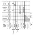
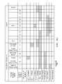
- FIGS. 3 and 4 A- 4 Gare diagrammatic representations of valve and motor timings for various embodiments of dispense cycles
- FIG. 5is a flow chart illustrating one embodiment of a priming routine
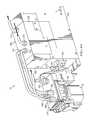
- FIGS. 6A and 6Bare diagrammatic representations of one embodiment of a pump
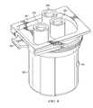
- FIG. 7is a diagrammatic representation of one embodiment of a filter and a manifold
- FIG. 8is a diagrammatic representation of one embodiment of a filter
- FIG. 9is a diagrammatic representation of one embodiment of a valve assembly
- FIG. 10is a diagrammatic representation of one embodiment of a pump and connections
- FIG. 11is a diagrammatic representation of one embodiment of a system for controlling operation of a pump
- FIG. 12is a flow chart illustrating of one embodiment of a method for affecting the operation of a pump using a filter information tag.
- Various embodiments described hereinare related to a pumping system that utilizes filter information to ensure proper operation of a pump.
- the filter informationis stored in an electronically readable tag that can be read by an appropriate tag reader.
- the filter informationcan be analyzed to determine proper operation of the pump.
- FIG. 1is a diagrammatic representation of one embodiment of a portion of a semiconductor manufacturing system 10 for dispensing fluid from a fluid reservoir 15 onto a wafer 17 .
- System 10can also include a pump controller 20 and pump 25 .
- Pump controller 20can be onboard pump 25 or connected to pump 25 via a one or more communications links for communicating control signals, data or other information.
- Pump controller 20controls pump 25 to dispense fluid onto wafer 17 .
- System 10can also include external valves such as a stop/suckback valve 27 that can prevent dripping at the dispense nozzle.
- Pump 25includes a removable filter 35 that has electronically readable filter information tag 40 containing filter information 45 .
- Filter information 45can include any information about filter 35 and other information that can be stored in an electronically readable tag.
- a tag reader 50to read filter information 45 from filter information tag 40 and provide the information to pump controller 20 , a system management computer or other computer.
- filter information tag 40can be an active or passive RFID tag and tag reader 50 can be an RFID tag reader.
- filter information tag 40can be a bar code or other optically readable code and tag reader 50 can be a bar code scanner or other scanner capable of reading tag 40 .
- filter information 45examples include, but are not limited to, part number, design style, membrane type, retention rating, generation of the filter, configuration of the filter membrane, lot number, serial number, a device flow, membrane thickness, membrane bubble point, particle quality, filter manufacturer quality information or other information.
- the design styleindicates the type of pump for which the filter is designed, the capacity/size of the filter, amount of membrane material in the filter or other information about the design of the filter.
- the membrane typeindicates the material and/or thickness of the membrane.
- the retention ratingindicates the size of particles that can be removed with a particular efficiency by the membrane.
- the generation of the filterindicates whether the filter is a first, second, third or other generation of the filter design.
- the configuration of the filter membraneindicates whether the filter is pleated, the type of pleating or other information regarding the design of the membrane.
- the serial numberprovides the serial number of the individual filter.
- the lot numbercan specify the manufacturing lot of the filter or membrane.
- the device flowindicates the flow rate the filter can handle while still producing good dispenses.
- the device flowcan be determined during manufacture for the individual filter.
- the membrane bubble pointprovides another measure of the flow rates/pressure the filter can handle and still produce good dispenses.
- the membrane bubble pointcan also be determined during manufacture for the individual filter.
- Filter information 45can include a part number that conveys a variety of information. For example, each letter in the example part number format “Aabcdefg” can convey a different piece of information. Table 1 below provides an example of information conveyed by the part number:
- the part number A2AT2RMR1 for an Impact pump filterwould indicate that the connectology of the filter, the filter is designed for an IntelliGen2 Pump (Impact and IntelliGen are trademarks of Entegris, Inc. of Chaska, Minn.), the membrane is thin UPE, has a retention rating of 10 nm, the filter is a version 2 filter, the filter includes an RFID tag, the filter membrane has an M-pleat, the filter is O-ringless and there is one filter per box.
- the use of a part number to convey informationis provided by way of example and filter information can be conveyed in other manners.
- filter 35can be coupled to pump 25 .
- Tag reader 50reads filter information 45 from tag 40 and communicates the filter information 45 to pump controller 20 .
- Pump controller 20processes filter information 45 or passes the filter information 45 on to a pump management system (discussed below). Pump controller 20 can apply rules to filter information 45 to determine whether and how to operate pump 25 . Additionally, pump controller 20 can adjust the operation of pump 25 during a dispense cycle based on filter information 45 .
- FIG. 2is a diagrammatic representation of one embodiment of a multi-stage pump 25 .
- Multi-stage pump 25includes a feed stage portion 105 and a separate dispense stage portion 110 .
- filter 35Located between feed stage portion 105 and dispense stage portion 110 , from a fluid flow perspective, is filter 35 to filter impurities from the process fluid.
- a number of valvescan control fluid flow through multi-stage pump 25 including, for example, inlet valve 125 , isolation valve 130 , barrier valve 135 , purge valve 140 , vent valve 145 and outlet valve 147 .
- Dispense stage portion 110can further include a pressure sensor 112 that determines the pressure of fluid at dispense stage 110 .
- the pressure determined by pressure sensor 112can be used to control the speed of the various pumps as described below.
- Example pressure sensorsinclude ceramic and polymer piezoresistive and capacitive pressure sensors, including those manufactured by Metallux AG, of Korb, Germany. According to one embodiment, the face of pressure sensor 112 that contacts the process fluid is a perfluoropolymer.
- Pump 25can include additional pressure sensors, such as a pressure sensor to read pressure in feed chamber 155 , temperature sensors and other sensors.
- Feed stage 105 and dispense stage 110can include rolling diaphragm pumps to pump fluid in multi-stage pump 25 .
- Feed-stage pump 150(“feed pump 150 ”), for example, includes a feed chamber 155 to collect fluid, a feed stage diaphragm 160 to move within feed chamber 155 and displace fluid, a piston 165 to move feed stage diaphragm 160 , a lead screw 170 and a stepper motor 175 .
- Lead screw 170couples to stepper motor 175 through a nut, gear or other mechanism for imparting energy from the motor to lead screw 170 .
- feed motor 170rotates a nut that, in turn, rotates lead screw 170 , causing piston 165 to actuate.
- Dispense-stage pump 180(“dispense pump 180 ”) can similarly include a dispense chamber 185 , a dispense stage diaphragm 190 , a piston 192 , a lead screw 195 , and a dispense motor 200 .
- Dispense motor 200can drive lead screw 195 through a threaded nut (e.g., a Torlon or other material nut).
- feed stage 105 and dispense stage 110can be a variety of other pumps including pneumatically or hydraulically actuated pumps, hydraulic pumps or other pumps.
- feed stage 105 and dispense stage 110can be a variety of other pumps including pneumatically or hydraulically actuated pumps, hydraulic pumps or other pumps.
- pneumatically actuated pumpfor the feed stage and a stepper motor driven hydraulic pump.
- a multi-stage pump using a pneumatically actuated pump for the feed stage and a stepper motor driven hydraulic pumpis described in U.S. patent application Ser. No. 11/051,576 entitled “PUMP CONTROLLER FOR PRECISION PUMPING APPARATUS” by inventors Zagars et al., filed Feb. 4, 2005, now issued as U.S. Pat. No. 7,476,087 on Jan. 13, 2009, hereby incorporated by reference.
- Feed motor 175 and dispense motor 200can be any suitable motor.
- dispense motor 200is a Permanent-Magnet Synchronous Motor (“PMSM”).
- the PMSMcan be controlled by a digital signal processor (“DSP”) utilizing Field-Oriented Control (“FOC”) or other type of position/speed control known in the art at motor 200 , a controller onboard multi-stage pump 25 or a separate pump controller (e.g. as shown in FIG. 1 ).
- PMSM 200can further include an encoder (e.g., a fine line rotary position encoder) for real time feedback of dispense motor 200 's position.
- an encodere.g., a fine line rotary position encoder
- a position sensorgives accurate and repeatable control of the position of piston 192 , which leads to accurate and repeatable control over fluid movements in dispense chamber 185 .
- a PMSMcan run at low velocities with little or no vibration.
- Feed motor 175can also be a PMSM or a stepper motor. It should also be noted that the feed pump can include a home sensor to indicate when the feed pump is in its home position.
- valves of multi-stage pump 25are opened or closed to allow or restrict fluid flow to various portions of multi-stage pump 25 .
- these valvescan be pneumatically actuated (i.e., gas driven) diaphragm valves that open or close depending on whether pressure or a vacuum is asserted. All or some of the valves can also be other types of valves.
- multi-stage pump 25can be controlled according to a variety of control schemes including, but not limited to those described in U.S. Provisional Patent Application No. 60/741,682 entitled “SYSTEM AND METHOD FOR PRESSURE COMPENSATION IN A PUMP” by Inventors Cedrone et al., filed Dec. 2, 2005; U.S. patent application Ser. No. 11/502,729 entitled “SYSTEMS AND METHODS FOR FLUID FLOW CONTROL IN AN IMMERSION LITHOGRAPHY SYSTEM” by Inventors Clarke et al., filed Aug. 11, 2006, now issued as U.S. Pat. No.
- multi-stage pump 25can include a ready segment, dispense segment, fill segment, pre-filtration segment, filtration segment, vent segment, purge segment and static purge segment.
- inlet valve 125is opened and feed stage pump 150 moves (e.g., pulls) feed stage diaphragm 160 to draw fluid into feed chamber 155 .
- feed stage pump 150moves feed stage diaphragm 160 to displace fluid from feed chamber 155 .
- Isolation valve 130 and barrier valve 135are opened to allow fluid to flow through filter 35 to dispense chamber 185 .
- Isolation valve 130can be opened first (e.g., in the “pre-filtration segment”) to allow pressure to build in filter 35 and then barrier valve 135 opened to allow fluid flow into dispense chamber 185 .
- both isolation valve 130 and barrier valve 135can be opened and the feed pump moved to build pressure on the dispense side of the filter.
- dispense pump 180can be brought to its home position.
- the home position of the dispense pumpcan be a position that gives the greatest available volume at the dispense pump for the dispense cycle, but is less than the maximum available volume that the dispense pump could provide.
- the home positionis selected based on various parameters for the dispense cycle to reduce unused hold up volume of multi-stage pump 25 .
- Feed pump 150can similarly be brought to a home position that provides a volume that is less than its maximum available volume.
- isolation valve 130is opened, barrier valve 135 closed and vent valve 145 opened.
- barrier valve 135can remain open during the vent segment and close at the end of the vent segment.
- the pressurecan be understood by the controller because the pressure in the dispense chamber, which can be measured by pressure sensor 112 , will be affected by the pressure in filter 35 .
- Feed-stage pump 150applies pressure to the fluid to remove air bubbles from filter 35 through open vent valve 145 .
- Feed-stage pump 150can be controlled to cause venting to occur at a predefined rate, allowing for longer vent times and lower vent rates, thereby allowing for accurate control of the amount of vent waste.
- feed pumpis a pneumatic style pump
- a fluid flow restrictioncan be placed in the vent fluid path, and the pneumatic pressure applied to feed pump can be increased or decreased in order to maintain a “venting” set point pressure, giving some control of an otherwise un-controlled method.
- isolation valve 130is closed, barrier valve 135 , if it is open in the vent segment, is closed, vent valve 145 closed, and purge valve 140 opened and inlet valve 125 opened.
- Dispense pump 180applies pressure to the fluid in dispense chamber 185 to vent air bubbles through purge valve 140 .
- purge valve 140remains open to continue to vent air. Any excess fluid removed during the purge or static purge segments can be routed out of multi-stage pump 25 (e.g., returned to the fluid source or discarded) or recycled to feed-stage pump 150 .
- inlet valve 125 , isolation valve 130 and barrier valve 135can be opened and purge valve 140 closed so that feed-stage pump 150 can reach ambient pressure of the source (e.g., the source bottle). According to other embodiments, all the valves can be closed at the ready segment.
- outlet valve 147opens and dispense pump 180 applies pressure to the fluid in dispense chamber 185 . Because outlet valve 147 may react to controls more slowly than dispense pump 180 , outlet valve 147 can be opened first and some predetermined period of time later dispense motor 200 started. This prevents dispense pump 180 from pushing fluid through a partially opened outlet valve 147 . Moreover, this prevents fluid moving up the dispense nozzle caused by the valve opening, followed by forward fluid motion caused by motor action. In other embodiments, outlet valve 147 can be opened and dispense begun by dispense pump 180 simultaneously.
- An additional suckback segmentcan be performed in which excess fluid in the dispense nozzle is removed.
- outlet valve 147can close and a secondary motor or vacuum can be used to suck excess fluid out of the outlet nozzle.
- outlet valve 147can remain open and dispense motor 200 can be reversed to such fluid back into the dispense chamber.
- the suckback segmenthelps prevent dripping of excess fluid onto the wafer.
- FIG. 3this figure provides a diagrammatic representation of valve and dispense motor timings for various segments of the operation of multi-stage pump 25 of FIG. 2 .
- Other sequencesare shown in FIGS. 4A-G . While several valves are shown as closing simultaneously during segment changes, the closing of valves can be timed slightly apart (e.g., 100 milliseconds) to reduce pressure spikes. For example, between the vent and purge segment, isolation valve 130 can be closed shortly before vent valve 145 . It should be noted, however, other valve timings can be utilized in various embodiments.
- the fill/dispense stagescan be performed at the same time, in which case both the inlet and outlet valves can be open in the dispense/fill segment.
- specific segmentsdo not have to be repeated for each cycle.
- the purge and static purge segmentsmay not be performed every cycle.
- the vent segmentmay not be performed every cycle.
- valvescan cause pressure spikes in the fluid within multi-stage pump 25 .
- outlet valve 147is closed during the static purge segment
- closing of purge valve 140 at the end of the static purge segmentcan cause a pressure increase in dispense chamber 185 .
- each valvemay displace a small volume of fluid when it closes. More particularly, in many cases before a fluid is dispensed from chamber 185 a purge cycle and/or a static purge cycle is used to purge air from dispense chamber 185 in order to prevent sputtering or other perturbations in the dispense of the fluid from multi-stage pump 25 .
- purge valve 140closes in order to seal dispense chamber 185 in preparation for the start of the dispense.
- purge valve 140forces a volume of extra fluid (approximately equal to the hold-up volume of purge valve 140 ) into dispense chamber 185 , which, in turn, causes an increase in pressure of the fluid in dispense chamber 185 above the baseline pressure intended for the dispense of the fluid.
- This excess pressure(above the baseline) may cause problems with a subsequent dispense of fluid.
- Various embodimentsaccount for the pressure increase due to various valve closings within the system to achieve a desirable starting pressure for the beginning of the dispense segment, account for differing head pressures and other differences in equipment from system to system by allowing almost any baseline pressure to be achieved in dispense chamber 185 before a dispense.
- dispense motor 200may be reversed to back out piston 192 a predetermined distance to compensate for any pressure increase caused by the closure of barrier valve 135 , purge valve 140 and/or any other sources which may cause a pressure increase in dispense chamber 185 .
- embodiments described hereinprovide a multi-stage pump with gentle fluid handling characteristics. By compensating for pressure fluctuations in a dispense chamber before a dispense segment, potentially damaging pressure spikes can be avoided or mitigated.
- Embodiments of a multi-stage pumpcan also employ other pump control mechanisms and valve timings to help reduce deleterious effects of pressure on a process fluid.
- pump 25may perform other operations.
- the filtershould be primed so that the filter membrane is fully wetted prior to running a dispense cycle.
- FIG. 5provides an illustrative example of steps for a priming routine, however other priming routines can be used as would be understood by those of ordinary skill in the art.
- step 205fluid is introduced into the dispense chamber.
- the filtercan be vented as described above for a period of time to remove air from the upstream portion of the filter (step 210 ).
- a purge-to-vent segmentcan occur (step 215 ). In this segment, the isolate and purge valves are opened and the barrier valve is closed.
- the dispense motoris run so that fluid flows out of the dispense chamber and through the vent. This can be followed by a filtration segment (step 216 ), a vent segment (step 217 ) and a purge segment (step 218 ).
- the filtercan be pressurized (step 220 ).
- the barrier valve and vent valvecan be closed, while the isolate valve is opened and the feed stage motor moved to pressurize the fluid.
- a forward flush segmentcan occur in which fluid is run through the filter to the dispense chamber and purged out the purge valve (step 225 ).
- a purge-to-vent segmentcan occur again (step 230 ).
- the priming routinecan be repeated as needed or desired.
- the priming routinecan involve any number of different steps and to ensure that the filter membrane is fully wetted.
- Some non-limiting examples of sequences of segments that can be used in a priming routineinclude, but are not limited to: i) a fill segment, a vent segment; ii) a fill segment, a purge to vent segment, a filtration segment, a vent segment, a purge to inlet segment; iii) a dispense segment, a fill segment, a filtration segment and a purge segment. Additional or alternative segments can be used in priming routines as needed or desired.
- FIG. 6Ais a diagrammatic representation of one embodiment of pump 25 having a pump main body 300 and a manifold 325 .
- Pump 25can include a dispense block 305 that at least partially defines the fill chamber, dispense chamber and portions of flow passages described above in conjunction with FIG. 2 .
- Dispense block 305can be a unitary block of PTFE, modified PTFE or other material. Because these materials do not react with or are minimally reactive with many process fluids, the use of these materials allows flow passages and pump chambers to be machined directly into dispense block 305 with a minimum of additional hardware.
- Dispense block 305can include various external inlets and outlets including, for example, inlet 310 through which the fluid is received and dispense outlet 315 through which fluid is dispensed during the dispense segment. Dispense block 305 , in the example of FIG. 6A , does not include an external purge outlet as purged fluid can be routed back to the feed chamber. In other embodiments, however, fluid can be purged externally.
- a valve plate 320can work in cooperation with dispense block 305 to form some or all of the valves of pump 25 .
- One embodiment of a valve plateis illustrated in FIG. 8 below. In other embodiments, some or all of the valves can be external.
- a cover 322provides protection for various components of pump 25 , including feed motor 175 and dispense motor 200 .
- Cover 322can also provide protection for pistons, pump controller 20 , fluid lines, pneumatic lines and other components.
- a manifold 325provides a connection for filter 35 .
- Filter 35can connect to manifold 325 using any suitable mechanism, including, but not limited to the filter connections described in U.S. Provisional Patent Application No. 60/741,667, entitled “O-RING-LESS LOW PROFILE FITTING AND ASSEMBLY THEREOF” by Inventor Gashgaee, filed Dec. 2, 2005; and U.S. patent application Ser. No. 11/602,513, entitled “O-RING-LESS LOW PROFILE FITTINGS AND FITTING ASSEMBLIES” by Inventor Gashgaee, filed Nov. 20, 2006 now issued as U.S. Pat. No. 7,547,049 on Jun.
- Manifold 325can connect internally or externally to flow passages in dispense block 305 .
- Manifold 325can include an integrated tag reader 50 that is positioned to read a filter information tag on the filter.
- an outlet 330 from dispense block 305can be in fluid communication with an inlet 335 on manifold 325 and an outlet 340 from manifold 325 can be in fluid communication with an inlet 345 on dispense block 305 to complete a flow path for filter 35 connected to manifold 325 .
- manifold 325can include a vent outlet 350 that can be in fluid communication with an external vent valve.
- Manifold 325 and the pump main body 300can include connections 355 and 360 to allow integrated tag reader 50 to electrically connect to the pump controller.
- Pump 25can also include inlet 365 and outlet 370 that can connect to vacuum and pressure sources. According to one embodiment, selective application of vacuum or pressure can be used to open and close various valves defined by valve plate 320 .
- FIG. 6Billustrates that pump 25 can include connections 375 for various communications links and power. Connections 375 , according to one embodiment, can be configured so that pump 25 can hook into existing electrical tracks for pumps.
- FIG. 7is a diagrammatic representation of one embodiment of filter 35 connected to manifold 325 .
- Manifold 325can include a quick change mechanism 377 for filters to allow filters to be easily connected to or removed from manifold 325 .
- Any quick change mechanism or other mechanism known or developed in the art for connecting a filter 35 to manifold 325 or to otherwise connect filter 35 to the pumpcan be used.
- One embodiment of a connection mechanism for a filteris described in PCT Patent Applicant No. PCT/US2008/082289 (Publication No. 2009/059324), filed Nov. 3, 2008, entitled “O-Ringless Seal Couplings”, by Towle et al. which claims priority to United States Provisional Application No.
- filter 35can include a bowl 380 and head 387 .
- Bowl 380can be shaped to accommodate a filter cartridge and head 387 can be shaped to accommodate a quick change mechanism of manifold 325 .
- Tag reader 50is positioned to read a filter information tag attached to or embedded in filter 35 .
- FIG. 8illustrates one embodiment of filter 35 .
- Head 387can include an outlet port 389 , vent port 390 and inlet port 392 that are sized and shaped to complement ports on manifold 325 . O-rings can be disposed in outlet port 389 , vent port 390 and inlet port 392 to prevent leaks.
- head 387can include a filter information tag 40 .
- a RFID, Bluetooth, IR, other wireless protocol or other identification devicecan be placed on filter 35 .
- the identification devicecan include manufacturer information about the filter (type of filter, retention rating, protocol for running the filter (by way of example, but not limitation, recipe variables, parameters, equations, curves for operations using the filter), priming/filling sequence for the filter pressure drop characteristics, flow rate, pore size or other information).
- Head 387can be shaped and sized to allow insertion into a quick change out device of a pump. For ease of installation, head 387 can include a handle portion 395 that can include features to ease gripping by a robot or human.
- filter information tag 40is illustrated as attached to the side of filter 35 , filter information tag 40 can also be coupled to filter 35 in other manners. For example, filter information tag 40 can be press fit in a tag receiving portion of bowl 380 or head 387 . In other embodiment, filter information tag 40 can be embedded in material that forms head 387 or bowl 387 . Filter information tag can be otherwise coupled to filter 35 .
- FIG. 9is a diagrammatic representation of one embodiment of a valve assembly comprising dispense block 305 and valve plate 320 to form a valve 400 .
- Valve plate 320can provide a valve housing for a system of valves including one or more of inlet valve 125 , isolation valve 130 , barrier valve 135 and purge valve 140 .
- each valveis at least partially integrated into valve plate 320 and is a diaphragm valve that is either opened or closed depending on whether pressure or vacuum is applied to the corresponding diaphragm.
- some of the valvesmay be external to dispense block 305 , arranged in additional valve plates or otherwise provided.
- a sheet of material 405is sandwiched between valve plate 320 and dispense block 305 to form the diaphragms of the various valves.
- material 305can be a sheet of PTFE or other flexible material.
- Valve plate 320forms a valve seat 410 into which material 405 can move.
- valve seat 410has a shape to which material 405 can contour without leaving dead space.
- An O-ring 415can be disposed in an annular groove 420 around the edge of each valve. O-ring 415 can be disposed on the valve plate side, dispense block side or O-rings can be disposed on both sides. Fluid can flow into and out of valve 400 through fluid flow passage 425 and 430 .
- valve plate 320can be configured to reduce the hold-up volume of the valve, eliminate volume variations due to vacuum fluctuations, reduce vacuum requirements and reduce stress on the valve diaphragm.
- Example valve configurationsare described in U.S. patent application Ser. No. 11/602,464 entitled “SYSTEM AND METHOD FOR A PUMP WITH REDUCED FORM FACTOR” by inventors Cedrone et al, filed Nov. 20, 2006; and U.S. patent application Ser. No. 12/218,325 entitled “METHOD AND SYSTEM FOR HIGH VISCOSITY PUMP” by inventors Cedrone et al, filed Jul. 14, 2008; which are hereby fully incorporated by reference herein
- Valve plate 320can include a valve control inlet 435 for each valve to apply pressure or vacuum to the corresponding diaphragm or portion of a diaphragm.
- a valve control inlet 435for each valve to apply pressure or vacuum to the corresponding diaphragm or portion of a diaphragm.
- the corresponding valvesare opened and closed so that fluid flow from inlet 425 to outlet 430 is restricted or allowed.
- the application of pressure or vacuumcan be regulated by a solenoid valve 440 that either opens valve control supply line 445 to pressure from a pressure source 450 or vacuum from a vacuum source 455 .
- FIG. 10is a diagrammatic representation of one embodiment of pump 25 and connections to other components.
- pump 25includes an on-board pump controller that can be connected to pump track 460 .
- Pump track 460can allow multiple pumps to be set up in a compact space and can provide connections for I/O signals (represented at 465 ), serial communications (represented at 470 ) and electrical connections (represented at 475 ).
- Track 460can also provide pneumatic connections for pressure/vacuum used to open and close valves (represented at 480 ).
- the inlet of pump 25can be connected to a fluid supply, such as resist bottle or other fluid supply 15 .
- the output of pump 25can be connected to a stop and suckback valve between the outlet of pump 25 and the wafer.
- Pump 25can include internal or external fluid connections (represented at 495 ) between manifold 325 and other portions of pump 25 . Additionally, pump 25 can include electrical connections (represented at 497 ) between the tag reader of manifold 325 and the pump controller or other electronics of pump 25 .
- FIG. 11is a diagrammatic representation of one embodiment of a system for controlling the operation of pump 25 .
- Pump controller 20can be onboard pump 25 or connected to pump 25 via one or more communications links for communicating control signals, data or other information.
- Pump controller 20can be implemented as an onboard PCB board, remote controller or in other suitable manner. Additionally, the functionality of pump controller 20 can be distributed between an onboard controller and another controller.
- pump controller 20can include a computer readable medium 55 (e.g., RAM, ROM, Flash memory, optical disk, magnetic drive or other computer readable medium) containing a set of control instructions 60 for controlling the operation of multi-stage pump 20 .
- a processor 65e.g., CPU, ASIC, RISC, DSP or other processor
- processors 65can execute the instructions.
- One example of a processoris the Texas Instruments TMS320F2812PGFA 16-bit DSP (Texas Instruments is Dallas, Tex. based company).
- instructions 60can be implemented as hardware.
- pump controller 20can include a variety of computer components known in the art including additional processors, memories, interfaces, display devices, peripherals or other computer components not shown for the sake of simplicity.
- a set of interfaces 70can allow pump controller 20 to communicate serial, parallel or analog data/signals to motors, valves or other components and receive data/signals from sensors, tag reader 50 , controllers or other components of pump 25 .
- pump controller 20can send signals to feed motor 175 (see FIG. 2 ), dispense motor 200 (see FIG. 2 ), solenoids to control solenoid valves 840 (see FIG. 9 ) and other components of pump 25 .
- Pump controller 20can generate signals to directly control components or can generate signals that are interpreted by valve, motor or other controllers to operate components of pump 25 .
- Pump controller 20can also receive analog or digital signals from sensors, such as pressure sensor 112 (see FIG. 2 ), tag reader 50 and other components of pump 25 .
- Interfaces 70can include analog and digital interfaces as needed and there may be additional components between interfaces 70 and processor 65 , such as, but not limited to, analog to digital converters, filters and other signal processing components.
- pump controller 20can also include an interface 80 to connect to a pump management system.
- Interface 80can allow pump controller 20 to connect to a network (e.g., Ethernet, wireless network, global area network, DeviceNet network or other network known or developed in the art), a bus (e.g., SCSI bus) or other communications link.
- An I/O interface connectorcan be used to connect pump controller 20 to a variety of interfaces and manufacturing tools.
- Example I/O interface connectorscan be found in United States Provisional Patent Application No. 60/741,657, entitled “I/O INTERFACE SYSTEM AND METHOD FOR A PUMP,” by Cedrone et al., filed Dec. 2, 2005; and U.S. patent application Ser. No.
- Pump controller 20can connect to a pump management system 85 that can provide instructions to pump controller 20 on the operation of pump 25 .
- Pump management system 85can be a computer or network of computers that connect to pump controller 20 to provide dispense recipes or other information to pump controller 20 .
- Pump management system 85can also collect operational data from pump controller 20 .
- Pump management system 85can connect to multiple pumps to provide centralized control and data collection.
- pump management system 85can maintain a data repository 90 of operational data 97 collected from a number of pumps.
- Data repositorycan be a database, file system or other data storage system.
- pump controller 20can receive filter information 45 from tag reader 50 .
- Pump controller 20can execute instructions 60 to analyze information 45 and determine whether or how to operate pump 25 .
- pump controller 20can apply rules to information 45 .
- pump controller 20can compare information 45 to stored information 95 to determine whether to operate the pump. By way of example, but not limitation, this can include comparing a part number to an expected part number to determine if the filter is acceptable to be used with pump 25 . Additionally, if the filter is acceptable, pump controller 20 can determine how to operate pump 25 based on filter information 45 .
- pump controller 20can send filter information 45 to pump management system 85 and pump management system 85 can apply rules to determine whether or how to operate pump 25 .
- Stored information 95can be provided to pump controller 20 through a user interface, by pump management system 85 or other can be otherwise provided.
- pump controller 20can store information 95 from a particular filter. If, for example, it is known that the first filter used with pump 25 is the proper filter, pump controller 20 can store filter information 45 from this filter as stored information 95 .
- Pump controller 20can also store operational data 97 and correlate the operational data 97 to filter information 45 .
- pump controller 20can forward operational data 97 to pump management system 85 and pump management system 85 can correlate the operational data 97 to filter information 45 .
- Pump controller 20may initially apply a rule such that a filter having a particular part number is acceptable. However, if over time it is discovered that filters having that part number and a first range of membrane bubble points resulted in good dispenses, but filters having the same part number and a second range of membrane bubble points resulted in an increased number of bad dispenses, the pump controller 20 or pump management system 85 can update the rules such that pump controller 20 will not operate with a filter having a membrane bubble point in the second range of membrane bubble points, even if the filter has an acceptable part number. Thus, analysis of data can be used to update the decision making of pump controller 20 or pump management system 85 .
- FIG. 12is a diagrammatic representation of one embodiment of a method for controlling the operation of a pump based on filter information.
- Various processing steps in FIG. 12can be performed by pump controller 20 , pump management system 85 or other device.
- an electronic tag readercan read a set of filter information from the tag (step 510 ).
- a set of rulescan be applied to the filter information to determine if the filter is appropriate (step 515 ).
- the rules for determining whether a filter is appropriatecan depend on the filter information and other factors, such as the process fluid, environmental properties, required cycle time or other factors.
- a rulemay be applied such that, if the process fluid has a certain viscosity, a filter will only be considered appropriate if it has a specific part number or certain part number and bubble point.
- the rules appliedcan depend on multiple pieces of filter information and other information. If the filter is not an appropriate filter, a corresponding action can be taken (step 520 ). Otherwise, operation of the pump can proceed (step 525 ).
- a filter part numbercan be compared to an expected or allowable part number to determine if the part number matches (step 515 ). If the part number matches, operation of the pump can proceed (step 525 ). If the part number does not match, the pump controller (or other device) can determine that operation of the pump should not proceed (step 520 ). An alarm or notification can be generated to notify a pump management system or human user that the filter connected to the pump is not appropriate. The steps of FIG. 12 can be repeated as needed or desired. If the filter is appropriate for a dispense operation, the filter information can be used to determine the operating routine of the pump.
- the terms “comprises,” “comprising,” “includes,” “including,” “has,” “having” or any other variation thereof,are intended to cover a non-exclusive inclusion.
- a process, product, article, or apparatus that comprises a list of elementsis not necessarily limited to only those elements but may include other elements not expressly listed or inherent to such process, article, or apparatus.
- “or”refers to an inclusive or and not to an exclusive or. For example, a condition A or B is satisfied by any one of the following: A is true (or present) and B is false (or not present), A is false (or not present) and B is true (or present), and both A and B are true (or present).
- any examples or illustrations given hereinare not to be regarded in any way as restrictions on, limits to, or express definitions of, any term or terms with which they are utilized. Instead these examples or illustrations are to be regarded as being described with respect to one particular embodiment and as illustrative only. Those of ordinary skill in the art will appreciate that any term or terms with which these examples or illustrations are utilized encompass other embodiments as well as implementations and adaptations thereof which may or may not be given therewith or elsewhere in the specification and all such embodiments are intended to be included within the scope of that term or terms. Language designating such non-limiting examples and illustrations includes, but is not limited to: “for example,” “for instance,” “e.g.,” “in one embodiment,” and the like.
Landscapes
- Engineering & Computer Science (AREA)
- Mechanical Engineering (AREA)
- General Engineering & Computer Science (AREA)
- Computer Hardware Design (AREA)
- Physics & Mathematics (AREA)
- General Physics & Mathematics (AREA)
- Automation & Control Theory (AREA)
- Reciprocating Pumps (AREA)
- Details Of Reciprocating Pumps (AREA)
- Control Of Positive-Displacement Pumps (AREA)
- Separation Using Semi-Permeable Membranes (AREA)
- Exposure Of Semiconductors, Excluding Electron Or Ion Beam Exposure (AREA)
Abstract
Description
| TABLE 1 | ||
| Letter | Information | Examples |
| A | Connectology | |
| a | Design Style --Indicates the | For IntelliGen Pump Filters: |
| type of pump for which the | P = wide body pump | |
| filter is designed. | (IntelliGen1 or IntelliGen2) | |
| 2 or M = IntelliGen3 or | ||
| IntelliGen Mini Pump | ||
| b | Membrane Type-Type of | A = thin UPE |
| Membrane Used in Filter | U = thick UPE | |
| S = asymmetric | ||
| D = Duo (nylon and UPE or | ||
| other combination) | ||
| M = PCM (chemically | ||
| modified UPE) | ||
| N = nylon | ||
| c | Retention Rating of | G = 0.2 um |
| membrane | V = 0.1 um | |
| Z = 0.05 um | ||
| Y = 30 nm | ||
| X = 20 nm | ||
| T = 10 nm | ||
| F = 5 nm | ||
| K = 3 nm | ||
| d | Generation-generation of | 0 = |
| filter | ||
| 2 = V2 | ||
| e | RFID | R = RFID |
| f | Pleat-Type of Pleating | 0 = Standard |
| Used in Filter | M = M pleat | |
| g | Where O-Ring is Located | 0 = OM |
| K = Karlez | ||
| E = EPDM | ||
| R = O-ringless | ||
| h | How Many Filters in a | 1 = 1 per |
| 3 = 3 per box | ||
Claims (17)
Priority Applications (9)
| Application Number | Priority Date | Filing Date | Title |
|---|---|---|---|
| US12/714,126US8684705B2 (en) | 2010-02-26 | 2010-02-26 | Method and system for controlling operation of a pump based on filter information in a filter information tag |
| KR1020127025136AKR101829078B1 (en) | 2010-02-26 | 2011-02-18 | Apparatus and method for controlling operation of a pump based on filter information in a filter information tag |
| EP11712362.0AEP2539589B1 (en) | 2010-02-26 | 2011-02-18 | Apparatus and method for controlling operation of a pump based on filter information in a filter information tag |
| CN201180010852.3ACN102770667B (en) | 2010-02-26 | 2011-02-18 | Apparatus and method for controlling operation of a pump based on filter information in a filter information tag |
| JP2012555054AJP5781549B2 (en) | 2010-02-26 | 2011-02-18 | Method and system for controlling pump operation based on filter information in filter information tag |
| PCT/US2011/025402WO2011106253A1 (en) | 2010-02-26 | 2011-02-18 | Apparatus and method for controlling operation of a pump based on filter information in a filter information tag |
| TW104136080ATWI595157B (en) | 2010-02-26 | 2011-02-25 | Method and system for controlling operation of a pump based on filter information in a filter information tag |
| TW100106550ATWI515368B (en) | 2010-02-26 | 2011-02-25 | Method and system for controlling operation of a pump based on filter information in a filter information tag |
| US14/175,573US9354637B2 (en) | 2010-02-26 | 2014-02-07 | Method and system for controlling operation of a pump based on filter information in a filter information tag |
Applications Claiming Priority (1)
| Application Number | Priority Date | Filing Date | Title |
|---|---|---|---|
| US12/714,126US8684705B2 (en) | 2010-02-26 | 2010-02-26 | Method and system for controlling operation of a pump based on filter information in a filter information tag |
Related Child Applications (1)
| Application Number | Title | Priority Date | Filing Date |
|---|---|---|---|
| US14/175,573ContinuationUS9354637B2 (en) | 2010-02-26 | 2014-02-07 | Method and system for controlling operation of a pump based on filter information in a filter information tag |
Publications (2)
| Publication Number | Publication Date |
|---|---|
| US20110211975A1 US20110211975A1 (en) | 2011-09-01 |
| US8684705B2true US8684705B2 (en) | 2014-04-01 |
Family
ID=44145770
Family Applications (2)
| Application Number | Title | Priority Date | Filing Date |
|---|---|---|---|
| US12/714,126Active2031-05-26US8684705B2 (en) | 2010-02-26 | 2010-02-26 | Method and system for controlling operation of a pump based on filter information in a filter information tag |
| US14/175,573Active2030-04-02US9354637B2 (en) | 2010-02-26 | 2014-02-07 | Method and system for controlling operation of a pump based on filter information in a filter information tag |
Family Applications After (1)
| Application Number | Title | Priority Date | Filing Date |
|---|---|---|---|
| US14/175,573Active2030-04-02US9354637B2 (en) | 2010-02-26 | 2014-02-07 | Method and system for controlling operation of a pump based on filter information in a filter information tag |
Country Status (7)
| Country | Link |
|---|---|
| US (2) | US8684705B2 (en) |
| EP (1) | EP2539589B1 (en) |
| JP (1) | JP5781549B2 (en) |
| KR (1) | KR101829078B1 (en) |
| CN (1) | CN102770667B (en) |
| TW (2) | TWI515368B (en) |
| WO (1) | WO2011106253A1 (en) |
Cited By (14)
| Publication number | Priority date | Publication date | Assignee | Title |
|---|---|---|---|---|
| US20120128505A1 (en)* | 2010-10-20 | 2012-05-24 | Entegris, Inc. | Method and System for Pump Priming |
| US20140306797A1 (en)* | 2013-02-12 | 2014-10-16 | Bofa International Limited | Filter assemblies |
| US9354637B2 (en) | 2010-02-26 | 2016-05-31 | Entegris, Inc. | Method and system for controlling operation of a pump based on filter information in a filter information tag |
| USD868287S1 (en) | 2017-11-29 | 2019-11-26 | Megadyne Medical Products, Inc. | Remote activation clip |
| USD868236S1 (en) | 2017-11-29 | 2019-11-26 | Megadyne Medical Products, Inc. | Smoke evacuation device control panel |
| US10631916B2 (en) | 2017-11-29 | 2020-04-28 | Megadyne Medical Products, Inc. | Filter connection for a smoke evacuation device |
| USD886976S1 (en) | 2017-11-29 | 2020-06-09 | Megadyne Medical Products, Inc. | Filter cartridge |
| US10758856B2 (en) | 2017-11-29 | 2020-09-01 | Megadyne Medical Products, Inc. | Filter medium compression system for smoke evacuation |
| US10758855B2 (en) | 2017-11-29 | 2020-09-01 | Megadyne Medical Products, Inc. | Smoke evacuation system fluid trap |
| US10758293B2 (en) | 2017-11-29 | 2020-09-01 | Megadyne Medical Products, Inc. | Smoke evacuation device inlet and outlet manifolds |
| USD912762S1 (en) | 2017-11-29 | 2021-03-09 | Megadyne Medical Products, Inc. | Fluid trap |
| US11234754B2 (en) | 2017-11-29 | 2022-02-01 | Megadyne Medical Products, Inc. | Smoke evacuation device |
| US11389225B2 (en) | 2017-11-29 | 2022-07-19 | Megadyne Medical Products, Inc. | Smoke evacuation device remote activation system |
| US11725664B2 (en) | 2017-11-29 | 2023-08-15 | Megadyne Medical Products, Inc. | Noise and vibration management for smoke evacuation system |
Families Citing this family (12)
| Publication number | Priority date | Publication date | Assignee | Title |
|---|---|---|---|---|
| US6879876B2 (en) | 2001-06-13 | 2005-04-12 | Advanced Technology Materials, Inc. | Liquid handling system with electronic information storage |
| KR101422303B1 (en) | 2006-07-10 | 2014-08-13 | 어드밴스드 테크놀러지 머티리얼즈, 인코포레이티드 | Systems and methods for managing material storage vessels having information storage elements |
| US8727744B2 (en)* | 2010-02-26 | 2014-05-20 | Entegris, Inc. | Method and system for optimizing operation of a pump |
| EP2745310B1 (en)* | 2011-08-19 | 2020-05-06 | Entegris, Inc. | System and method for detecting air in a fluid |
| IN2013CH05498A (en)* | 2013-11-28 | 2015-06-12 | Bosch Ltd | |
| JP5925371B1 (en)* | 2015-09-18 | 2016-05-25 | 三菱日立パワーシステムズ株式会社 | Water quality management device, water treatment system, water quality management method, and water treatment system optimization program |
| US10286343B2 (en) | 2016-10-28 | 2019-05-14 | Pall Corporation | Filter including RFID tag |
| US20180209890A1 (en)* | 2017-01-23 | 2018-07-26 | Exhaust Filter Inspections, Llc | Diesel particulate filter inspection machine |
| WO2018165146A1 (en) | 2017-03-06 | 2018-09-13 | Cummins Filtration Ip, Inc. | Genuine filter recognition with filter monitoring system |
| DE112018004801T5 (en) | 2017-08-30 | 2020-06-18 | Cummins Filtration Ip, Inc. | LOCKING DEVICE FOR DETECTING ORIGINAL FILTERS |
| US11007526B2 (en)* | 2018-07-06 | 2021-05-18 | Qorvo Us, Inc. | Capless sample well port for a cartridge |
| JP2023155677A (en)* | 2022-04-11 | 2023-10-23 | マクセル株式会社 | Water purifier |
Citations (113)
| Publication number | Priority date | Publication date | Assignee | Title |
|---|---|---|---|---|
| US3660200A (en) | 1969-07-09 | 1972-05-02 | Robert E Anderson | Process for bonding preheated thermoplastic film to a dissimilar substrate |
| US4605591A (en) | 1983-10-27 | 1986-08-12 | Toyo Boseki Kabushiki Kaisha | Thermoplastic resin film laminate and production thereof |
| US4699298A (en) | 1985-03-20 | 1987-10-13 | Fsi Corporation | Bung connection |
| US4827110A (en) | 1987-06-11 | 1989-05-02 | Fluoroware, Inc. | Method and apparatus for monitoring the location of wafer disks |
| US4891254A (en) | 1988-06-17 | 1990-01-02 | Bianco James S | Article with embedded optically-readable identification means and method for making same |
| US4965933A (en) | 1989-05-22 | 1990-10-30 | The Cherry Corporation | Process for making insert molded circuit |
| US5108015A (en) | 1990-07-06 | 1992-04-28 | Fluoroware, Inc. | Multiple tube to bung coupling |
| US5152057A (en) | 1987-11-17 | 1992-10-06 | Mold-Pac Corporation | Molded integrated circuit package |
| US5194327A (en) | 1990-04-20 | 1993-03-16 | Teijin Limited | Antistatic polyester film |
| US5203060A (en) | 1989-05-22 | 1993-04-20 | Mraz James E | Apparatus for making insert molded circuitry |
| WO1994018700A1 (en) | 1993-02-11 | 1994-08-18 | Indala Corporation | Method of producing a radio frequency transponder with a molded environmentally sealed package |
| US5344703A (en) | 1991-06-25 | 1994-09-06 | The United States Of America As Represented By The Secretary Of The Air Force | Ordered polymer/sol-gel microcomposite laminates with peek resin adhesive |
| US5389769A (en) | 1992-03-27 | 1995-02-14 | Shinko Electric Co., Ltd. | ID recognizing system in semiconductor manufacturing system |
| US5448110A (en) | 1992-06-17 | 1995-09-05 | Micron Communications, Inc. | Enclosed transceiver |
| US5528222A (en) | 1994-09-09 | 1996-06-18 | International Business Machines Corporation | Radio frequency circuit and memory in thin flexible package |
| US5526956A (en) | 1992-09-11 | 1996-06-18 | Now Technologies, Inc. | Liquid chemical dispensing and recirculating system |
| US5779839A (en) | 1992-06-17 | 1998-07-14 | Micron Communications, Inc. | Method of manufacturing an enclosed transceiver |
| US5811197A (en) | 1996-03-21 | 1998-09-22 | Teijin Limited | Polyester film having low electrostatic and high adhesion properties |
| US5953682A (en) | 1997-02-14 | 1999-09-14 | Millipore Corporation | Automated gas cylinder tracking system |
| US5957328A (en) | 1992-09-11 | 1999-09-28 | Now Technologies, Inc. | Liquid chemical dispensing and recirculating system |
| US5973600A (en) | 1997-09-11 | 1999-10-26 | Precision Dynamics Corporation | Laminated radio frequency identification device |
| US5986569A (en) | 1997-03-20 | 1999-11-16 | Micron Communications, Inc. | Radio frequency identification system, radio frequency identification device package, and method of use of radio frequency identification device |
| US6013949A (en) | 1992-08-12 | 2000-01-11 | Micron Technology, Inc. | Miniature Radio Frequency Transceiver |
| WO2000002236A2 (en) | 1998-07-07 | 2000-01-13 | Memc Electronic Materials, Inc. | Radio frequency identification system and method for tracking silicon wafers |
| US6015068A (en) | 1998-02-04 | 2000-01-18 | Now Technologies, Inc. | Liquid chemical dispensing system with a key code ring for connecting the proper chemical to the proper attachment |
| US6025054A (en) | 1997-09-08 | 2000-02-15 | Cardxx, Inc. | Smart cards having glue-positioned electronic components |
| US6027027A (en) | 1996-05-31 | 2000-02-22 | Lucent Technologies Inc. | Luggage tag assembly |
| US6045000A (en) | 1997-12-02 | 2000-04-04 | Rauworth; Barry Lee | Blow molded drum |
| WO2000021030A1 (en) | 1998-10-06 | 2000-04-13 | Intermec Ip Corp. | Rfid transponder having improved rf characteristics |
| WO2000043952A1 (en) | 1999-01-22 | 2000-07-27 | Intermec Ip Corp. | Rfid transponder |
| US6100804A (en) | 1998-10-29 | 2000-08-08 | Intecmec Ip Corp. | Radio frequency identification system |
| US6147662A (en) | 1999-09-10 | 2000-11-14 | Moore North America, Inc. | Radio frequency identification tags and labels |
| US6164530A (en) | 1994-04-08 | 2000-12-26 | Fluoroware, Inc. | Disk carrier with transponder |
| US6177859B1 (en) | 1997-10-21 | 2001-01-23 | Micron Technology, Inc. | Radio frequency communication apparatus and methods of forming a radio frequency communication apparatus |
| US6190565B1 (en)* | 1993-05-17 | 2001-02-20 | David C. Bailey | Dual stage pump system with pre-stressed diaphragms and reservoir |
| US6195007B1 (en) | 1998-09-04 | 2001-02-27 | Sony Corporation | Recording medium handling apparatus |
| US6206282B1 (en) | 1998-03-03 | 2001-03-27 | Pyper Products Corporation | RF embedded identification device |
| US6209592B1 (en) | 1998-05-11 | 2001-04-03 | On Track Innovations Ltd. | Self-closing cap for the filling neck of a container |
| WO2001040646A2 (en) | 1999-11-30 | 2001-06-07 | Mykrolis Corporation | Vertically oriented pump for high viscosity fluids |
| US6248199B1 (en) | 1999-04-26 | 2001-06-19 | Soundcraft, Inc. | Method for the continuous fabrication of access control and identification cards with embedded electronics or other elements |
| US6255949B1 (en) | 1997-10-15 | 2001-07-03 | Escort Memory Systems | High temperature RFID tag |
| US6259367B1 (en) | 1999-09-28 | 2001-07-10 | Elliot S. Klein | Lost and found system and method |
| US6303036B1 (en)* | 1998-07-31 | 2001-10-16 | Nephros, Inc. | Method and apparatus for efficient hemodiafiltration |
| US6302461B1 (en) | 1997-09-22 | 2001-10-16 | Compagnie Plastic Omnium | Transport and/or collection device made of molded plastics material and including an identity device, and a method of manufacture |
| US6325294B2 (en) | 1992-06-17 | 2001-12-04 | Micron Technology, Inc. | Method of manufacturing an enclosed transceiver |
| US6340932B1 (en) | 1998-06-02 | 2002-01-22 | Rf Code, Inc. | Carrier with antenna for radio frequency identification |
| JP2002024783A (en) | 2000-07-03 | 2002-01-25 | Kobayashi Kirokushi Co Ltd | Rf tag |
| JP2002183695A (en) | 2000-12-18 | 2002-06-28 | Hanex Co Ltd | Rfid tag structure and installing structure therefor |
| WO2002056344A2 (en) | 2001-01-10 | 2002-07-18 | Entegris Cayman Ltd. | Transportable container including an internal environment monitor |
| US20020124945A1 (en) | 2000-02-11 | 2002-09-12 | Ron Muir | In-mold label with perforations |
| US6451154B1 (en) | 2000-02-18 | 2002-09-17 | Moore North America, Inc. | RFID manufacturing concepts |
| JP2002298116A (en) | 2001-03-30 | 2002-10-11 | Mitsubishi Materials Corp | Tag for use in rfid |
| US6483434B1 (en) | 1999-10-20 | 2002-11-19 | Ifco System Europe Gmbh | Container tracking system |
| US20030010387A1 (en) | 2001-07-12 | 2003-01-16 | Entegris, Inc. | High volume dispense head with seal verification and low foam return line |
| US6522549B2 (en) | 2000-09-29 | 2003-02-18 | Sony Corporation | Non-contacting type IC card and method for fabricating the same |
| US20030135388A1 (en) | 2002-01-11 | 2003-07-17 | James Martucci | Medication delivery system |
| WO2003060818A2 (en) | 2002-01-09 | 2003-07-24 | Alcoa Closure Systems International, Inc. | Method of making a closure for a package containing a rfid circuit |
| US6609041B1 (en) | 1999-05-05 | 2003-08-19 | Johnson & Johnson Vision Care, Inc. | Method and system for SKU tracking and changeover |
| US6661339B2 (en) | 2000-01-24 | 2003-12-09 | Nextreme, L.L.C. | High performance fuel tank |
| US20040041709A1 (en) | 2002-05-23 | 2004-03-04 | Forster Ian J. | Device and method for identifying a containers |
| US6718888B2 (en) | 2000-04-11 | 2004-04-13 | Nextreme, Llc | Thermoformed platform |
| US6720877B2 (en) | 2001-03-29 | 2004-04-13 | Sensormatic Electronics Corporation | Manufacturing methods for magnetomechanical electronic article surveillance markers |
| US6720865B1 (en) | 2000-02-11 | 2004-04-13 | Marconi Intellectual Property (Us) | Resilient member with wireless communication device |
| US20040094949A1 (en) | 2002-11-14 | 2004-05-20 | Savagian Michael D. | In-mold radio frequency identification device label |
| US6758000B2 (en) | 2001-01-10 | 2004-07-06 | Avery Dennison Corporation | Livestock security tag assembly |
| US6771981B1 (en) | 2000-08-02 | 2004-08-03 | Nokia Mobile Phones Ltd. | Electronic device cover with embedded radio frequency (RF) transponder and methods of using same |
| US6778089B2 (en) | 1999-05-17 | 2004-08-17 | Avid Identification Systems, Inc. | Overmolded transponder |
| US6816076B2 (en) | 2001-11-09 | 2004-11-09 | Allibert Equipement | Article adapted to be tracked by an electronic identifier |
| US20040238623A1 (en) | 2003-05-09 | 2004-12-02 | Wayne Asp | Component handling device having a film insert molded RFID tag |
| US20040262404A1 (en) | 2001-09-03 | 2004-12-30 | Yasutake Fujiki | Baggage tag and method for using baggage tag |
| US20050068182A1 (en) | 2003-09-30 | 2005-03-31 | Dunlap Richard L. | Application of radio frequency identification |
| US20050066563A1 (en) | 1997-03-12 | 2005-03-31 | Dodge Juhan | Identification device having reusable transponder |
| US6879876B2 (en) | 2001-06-13 | 2005-04-12 | Advanced Technology Materials, Inc. | Liquid handling system with electronic information storage |
| US6886246B2 (en) | 1998-10-15 | 2005-05-03 | Amerasia International Technology, Inc. | Method for making an article having an embedded electronic device |
| US20050099303A1 (en) | 2003-11-11 | 2005-05-12 | Zuckerman Andrew M. | Injection molded garment hanger |
| US6900536B1 (en) | 2002-04-26 | 2005-05-31 | Celis Semiconductor Corporation | Method for producing an electrical circuit |
| US20050128086A1 (en) | 2003-12-08 | 2005-06-16 | 3M Innovative Properties Company | Durable radio frequency indentification label and methods of manufacturing the same |
| US20050184087A1 (en) | 1998-11-23 | 2005-08-25 | Zagars Raymond A. | Pump controller for precision pumping apparatus |
| WO2005081182A2 (en) | 2004-02-12 | 2005-09-01 | Avery Dennison Corporation | Rfid tag and method of manufacturing the same |
| US6943678B2 (en) | 2000-01-24 | 2005-09-13 | Nextreme, L.L.C. | Thermoformed apparatus having a communications device |
| US20050199700A1 (en) | 2004-03-02 | 2005-09-15 | Newage Industries, Inc. | Method of attaching an RF ID tag to a hose and tracking system |
| US20050205658A1 (en) | 2004-03-16 | 2005-09-22 | Newage Industries, Inc. | Process equipment tracking system |
| US20050237195A1 (en) | 2004-04-27 | 2005-10-27 | Urban Brian J | Method and apparatus for placing ID tags in molded articles |
| US20050237184A1 (en) | 2000-01-24 | 2005-10-27 | Scott Muirhead | RF-enabled pallet |
| US20050280542A1 (en) | 2004-06-22 | 2005-12-22 | Yeng-Bao Shieh | Method for embedding RFID tag in object |
| US20050285735A1 (en) | 2004-04-28 | 2005-12-29 | Mamoru Imura | Tag assembly for radio frequency identification controlled heatable objects |
| US20060060512A1 (en) | 2002-02-15 | 2006-03-23 | 3M Innovative Properties | System for monitoring the performance of fluid treatment cartridges |
| DE10156927B4 (en) | 2001-11-21 | 2006-06-08 | Netzsch-Mohnopumpen Gmbh | Pump controller with part identification |
| GB2424928A (en) | 2005-04-05 | 2006-10-11 | Boc Group Plc | Vacuum pumping control arrangement |
| US20060283932A1 (en) | 2005-04-08 | 2006-12-21 | Wayne Asp | Identification tag for fluid containment drum |
| US7152781B2 (en) | 2003-12-01 | 2006-12-26 | Advanced Technology Materials, Inc. | Manufacturing system with intrinsically safe electric information storage |
| US20070104586A1 (en) | 1998-11-23 | 2007-05-10 | James Cedrone | System and method for correcting for pressure variations using a motor |
| US20070128050A1 (en) | 2005-11-21 | 2007-06-07 | James Cedrone | System and method for a pump with reduced form factor |
| US20070128048A1 (en) | 2005-12-02 | 2007-06-07 | George Gonnella | System and method for position control of a mechanical piston in a pump |
| US20070125797A1 (en) | 2005-12-02 | 2007-06-07 | James Cedrone | System and method for pressure compensation in a pump |
| US20070128046A1 (en) | 2005-12-02 | 2007-06-07 | George Gonnella | System and method for control of fluid pressure |
| US7273172B2 (en) | 2004-07-14 | 2007-09-25 | United Parcel Service Of America, Inc. | Methods and systems for automating inventory and dispatch procedures at a staging area |
| US20080131290A1 (en) | 2006-11-30 | 2008-06-05 | Entegris, Inc. | System and method for operation of a pump |
| US20080135498A1 (en) | 2006-12-11 | 2008-06-12 | International Business Machines Corporation | Method and apparatus for filter conditioning |
| US20080175719A1 (en)* | 2006-04-14 | 2008-07-24 | Deka Products Limited Partnership | Fluid pumping systems, devices and methods |
| US7456418B1 (en) | 2004-11-15 | 2008-11-25 | Visible Assets, Inc | RF-enablement of auditable storage for hazardous materials |
| JP2009018308A (en) | 2008-09-17 | 2009-01-29 | Entegris Inc | Connector device for filter cartridge |
| US20090045140A1 (en) | 2005-04-25 | 2009-02-19 | Joseph Zahka | Method and apparatus for treating fluids to reduce microbubbles |
| US20090047143A1 (en) | 2005-11-21 | 2009-02-19 | Entegris, Inc. | Method and system for high viscosity pump |
| WO2009059324A2 (en) | 2007-11-02 | 2009-05-07 | Entegris, Inc. | O-ringless seal couplings |
| US20090132094A1 (en) | 2004-11-23 | 2009-05-21 | Entegris, Inc. | System and Method for a Variable Home Position Dispense System |
| US7547049B2 (en) | 2005-12-02 | 2009-06-16 | Entegris, Inc. | O-ring-less low profile fittings and fitting assemblies |
| US20100247775A1 (en) | 2009-03-31 | 2010-09-30 | Abbott Diabetes Care Inc. | Precise Fluid Dispensing Method and Device |
| US20100262304A1 (en) | 2005-12-02 | 2010-10-14 | George Gonnella | System and method for valve sequencing in a pump |
| US7878765B2 (en) | 2005-12-02 | 2011-02-01 | Entegris, Inc. | System and method for monitoring operation of a pump |
| US7897196B2 (en) | 2005-12-05 | 2011-03-01 | Entegris, Inc. | Error volume system and method for a pump |
| US20110211976A1 (en) | 2010-02-26 | 2011-09-01 | Entegris, Inc. | Method and system for optimizing operation of a pump |
| US20120128505A1 (en) | 2010-10-20 | 2012-05-24 | Entegris, Inc. | Method and System for Pump Priming |
Family Cites Families (26)
| Publication number | Priority date | Publication date | Assignee | Title |
|---|---|---|---|---|
| US5222867A (en) | 1986-08-29 | 1993-06-29 | Walker Sr Frank J | Method and system for controlling a mechanical pump to monitor and optimize both reservoir and equipment performance |
| US5157605A (en) | 1987-04-27 | 1992-10-20 | Schlumberger Technology Corporation | Induction logging method and apparatus including means for combining on-phase and quadrature components of signals received at varying frequencies and including use of multiple receiver means associated with a single transmitter |
| JP2803859B2 (en) | 1989-09-29 | 1998-09-24 | 株式会社日立製作所 | Fluid supply device and control method thereof |
| JPH03114565U (en) | 1990-03-12 | 1991-11-25 | ||
| NL9300554A (en)* | 1993-03-29 | 1994-10-17 | Doctro A V V | Assembly of filter device and a replaceable filter; as well as filter device and filter for use therein. |
| US5490765A (en) | 1993-05-17 | 1996-02-13 | Cybor Corporation | Dual stage pump system with pre-stressed diaphragms and reservoir |
| US5443369A (en) | 1993-06-09 | 1995-08-22 | Ingersoll-Rand Company | Self-contained instrument and seal air system for a centrifugal compressor |
| US5482441A (en) | 1994-04-18 | 1996-01-09 | Permar; Clark | Liquid flow control system |
| JP3364155B2 (en) | 1998-06-05 | 2003-01-08 | 東京エレクトロン株式会社 | Coating film forming apparatus and method |
| GB9826671D0 (en) | 1998-12-03 | 1999-01-27 | Process Scient Innovations | Filters and active devices |
| KR100304703B1 (en) | 1999-02-09 | 2001-09-26 | 윤종용 | Semiconductor fabrication apparatus having controller sensing function of filter |
| JP2001082407A (en) | 1999-09-16 | 2001-03-27 | Kawatetsu Engineering Kk | Automatic changeover device and filter device using it |
| JP2001353640A (en) | 2000-06-16 | 2001-12-25 | Koike Engineering & Service Kk | Filtering device having back washing function |
| DE10042636C1 (en)* | 2000-08-30 | 2002-04-11 | Epcos Ag | Electrical component and method for its production |
| TW504400B (en) | 2001-01-31 | 2002-10-01 | Toshiba Corp | Filtering apparatus, back wash method therefor, filtering device and power plant |
| JP3832269B2 (en) | 2001-04-13 | 2006-10-11 | 住友化学株式会社 | Photoresist liquid product manufacturing method |
| US6848625B2 (en) | 2002-03-19 | 2005-02-01 | Tokyo Electron Limited | Process liquid supply mechanism and process liquid supply method |
| JP3862596B2 (en) | 2002-05-01 | 2006-12-27 | 東京エレクトロン株式会社 | Substrate processing method |
| US7481917B2 (en) | 2004-03-05 | 2009-01-27 | Hydranautics | Filtration devices with embedded radio frequency identification (RFID) tags |
| JP3969413B2 (en)* | 2004-09-29 | 2007-09-05 | 富士フイルム株式会社 | Liquid ejection device |
| CN102705213A (en)* | 2005-12-02 | 2012-10-03 | 恩特格里公司 | System and method for correcting for pressure variations using a motor |
| US20070240578A1 (en)* | 2006-04-12 | 2007-10-18 | Dileo Anthony | Filter with memory, communication and temperature sensor |
| US20070272327A1 (en) | 2006-04-27 | 2007-11-29 | Applied Materials, Inc. | Chemical dispense system |
| JP4983137B2 (en)* | 2006-08-03 | 2012-07-25 | 凸版印刷株式会社 | Filtration device and coating device using the same |
| US7443483B2 (en) | 2006-08-11 | 2008-10-28 | Entegris, Inc. | Systems and methods for fluid flow control in an immersion lithography system |
| US8684705B2 (en) | 2010-02-26 | 2014-04-01 | Entegris, Inc. | Method and system for controlling operation of a pump based on filter information in a filter information tag |
- 2010
- 2010-02-26USUS12/714,126patent/US8684705B2/enactiveActive
- 2011
- 2011-02-18JPJP2012555054Apatent/JP5781549B2/enactiveActive
- 2011-02-18KRKR1020127025136Apatent/KR101829078B1/enactiveActive
- 2011-02-18EPEP11712362.0Apatent/EP2539589B1/enactiveActive
- 2011-02-18WOPCT/US2011/025402patent/WO2011106253A1/enactiveApplication Filing
- 2011-02-18CNCN201180010852.3Apatent/CN102770667B/enactiveActive
- 2011-02-25TWTW100106550Apatent/TWI515368B/enactive
- 2011-02-25TWTW104136080Apatent/TWI595157B/enactive
- 2014
- 2014-02-07USUS14/175,573patent/US9354637B2/enactiveActive
Patent Citations (127)
| Publication number | Priority date | Publication date | Assignee | Title |
|---|---|---|---|---|
| US3660200A (en) | 1969-07-09 | 1972-05-02 | Robert E Anderson | Process for bonding preheated thermoplastic film to a dissimilar substrate |
| US4605591A (en) | 1983-10-27 | 1986-08-12 | Toyo Boseki Kabushiki Kaisha | Thermoplastic resin film laminate and production thereof |
| US4699298A (en) | 1985-03-20 | 1987-10-13 | Fsi Corporation | Bung connection |
| US4827110A (en) | 1987-06-11 | 1989-05-02 | Fluoroware, Inc. | Method and apparatus for monitoring the location of wafer disks |
| US5152057A (en) | 1987-11-17 | 1992-10-06 | Mold-Pac Corporation | Molded integrated circuit package |
| US4891254A (en) | 1988-06-17 | 1990-01-02 | Bianco James S | Article with embedded optically-readable identification means and method for making same |
| US4965933A (en) | 1989-05-22 | 1990-10-30 | The Cherry Corporation | Process for making insert molded circuit |
| US5203060A (en) | 1989-05-22 | 1993-04-20 | Mraz James E | Apparatus for making insert molded circuitry |
| US5194327A (en) | 1990-04-20 | 1993-03-16 | Teijin Limited | Antistatic polyester film |
| US5108015A (en) | 1990-07-06 | 1992-04-28 | Fluoroware, Inc. | Multiple tube to bung coupling |
| US5344703A (en) | 1991-06-25 | 1994-09-06 | The United States Of America As Represented By The Secretary Of The Air Force | Ordered polymer/sol-gel microcomposite laminates with peek resin adhesive |
| US5389769A (en) | 1992-03-27 | 1995-02-14 | Shinko Electric Co., Ltd. | ID recognizing system in semiconductor manufacturing system |
| US5448110A (en) | 1992-06-17 | 1995-09-05 | Micron Communications, Inc. | Enclosed transceiver |
| US5779839A (en) | 1992-06-17 | 1998-07-14 | Micron Communications, Inc. | Method of manufacturing an enclosed transceiver |
| US6325294B2 (en) | 1992-06-17 | 2001-12-04 | Micron Technology, Inc. | Method of manufacturing an enclosed transceiver |
| US6013949A (en) | 1992-08-12 | 2000-01-11 | Micron Technology, Inc. | Miniature Radio Frequency Transceiver |
| US5957328A (en) | 1992-09-11 | 1999-09-28 | Now Technologies, Inc. | Liquid chemical dispensing and recirculating system |
| US5526956A (en) | 1992-09-11 | 1996-06-18 | Now Technologies, Inc. | Liquid chemical dispensing and recirculating system |
| US5420757A (en) | 1993-02-11 | 1995-05-30 | Indala Corporation | Method of producing a radio frequency transponder with a molded environmentally sealed package |
| WO1994018700A1 (en) | 1993-02-11 | 1994-08-18 | Indala Corporation | Method of producing a radio frequency transponder with a molded environmentally sealed package |
| US6190565B1 (en)* | 1993-05-17 | 2001-02-20 | David C. Bailey | Dual stage pump system with pre-stressed diaphragms and reservoir |
| US6164530A (en) | 1994-04-08 | 2000-12-26 | Fluoroware, Inc. | Disk carrier with transponder |
| EP0855675A2 (en) | 1994-09-09 | 1998-07-29 | International Business Machines Corporation | Radio frequency circuit and memory in thin flexible package |
| US5528222A (en) | 1994-09-09 | 1996-06-18 | International Business Machines Corporation | Radio frequency circuit and memory in thin flexible package |
| US5811197A (en) | 1996-03-21 | 1998-09-22 | Teijin Limited | Polyester film having low electrostatic and high adhesion properties |
| US6027027A (en) | 1996-05-31 | 2000-02-22 | Lucent Technologies Inc. | Luggage tag assembly |
| US5953682A (en) | 1997-02-14 | 1999-09-14 | Millipore Corporation | Automated gas cylinder tracking system |
| US20050066563A1 (en) | 1997-03-12 | 2005-03-31 | Dodge Juhan | Identification device having reusable transponder |
| US5986569A (en) | 1997-03-20 | 1999-11-16 | Micron Communications, Inc. | Radio frequency identification system, radio frequency identification device package, and method of use of radio frequency identification device |
| US6025054A (en) | 1997-09-08 | 2000-02-15 | Cardxx, Inc. | Smart cards having glue-positioned electronic components |
| US5973600A (en) | 1997-09-11 | 1999-10-26 | Precision Dynamics Corporation | Laminated radio frequency identification device |
| US6302461B1 (en) | 1997-09-22 | 2001-10-16 | Compagnie Plastic Omnium | Transport and/or collection device made of molded plastics material and including an identity device, and a method of manufacture |
| US6255949B1 (en) | 1997-10-15 | 2001-07-03 | Escort Memory Systems | High temperature RFID tag |
| US6177859B1 (en) | 1997-10-21 | 2001-01-23 | Micron Technology, Inc. | Radio frequency communication apparatus and methods of forming a radio frequency communication apparatus |
| US6045000A (en) | 1997-12-02 | 2000-04-04 | Rauworth; Barry Lee | Blow molded drum |
| US6015068A (en) | 1998-02-04 | 2000-01-18 | Now Technologies, Inc. | Liquid chemical dispensing system with a key code ring for connecting the proper chemical to the proper attachment |
| US6206282B1 (en) | 1998-03-03 | 2001-03-27 | Pyper Products Corporation | RF embedded identification device |
| US6209592B1 (en) | 1998-05-11 | 2001-04-03 | On Track Innovations Ltd. | Self-closing cap for the filling neck of a container |
| US6340932B1 (en) | 1998-06-02 | 2002-01-22 | Rf Code, Inc. | Carrier with antenna for radio frequency identification |
| WO2000002236A2 (en) | 1998-07-07 | 2000-01-13 | Memc Electronic Materials, Inc. | Radio frequency identification system and method for tracking silicon wafers |
| US6330971B1 (en) | 1998-07-07 | 2001-12-18 | Memc Electronic Materials, Inc. | Radio frequency identification system and method for tracking silicon wafers |
| US6303036B1 (en)* | 1998-07-31 | 2001-10-16 | Nephros, Inc. | Method and apparatus for efficient hemodiafiltration |
| US6195007B1 (en) | 1998-09-04 | 2001-02-27 | Sony Corporation | Recording medium handling apparatus |
| WO2000021030A1 (en) | 1998-10-06 | 2000-04-13 | Intermec Ip Corp. | Rfid transponder having improved rf characteristics |
| US6886246B2 (en) | 1998-10-15 | 2005-05-03 | Amerasia International Technology, Inc. | Method for making an article having an embedded electronic device |
| US6100804A (en) | 1998-10-29 | 2000-08-08 | Intecmec Ip Corp. | Radio frequency identification system |
| US20050184087A1 (en) | 1998-11-23 | 2005-08-25 | Zagars Raymond A. | Pump controller for precision pumping apparatus |
| US7476087B2 (en) | 1998-11-23 | 2009-01-13 | Entegris, Inc. | Pump controller for precision pumping apparatus |
| US20070104586A1 (en) | 1998-11-23 | 2007-05-10 | James Cedrone | System and method for correcting for pressure variations using a motor |
| US7029238B1 (en) | 1998-11-23 | 2006-04-18 | Mykrolis Corporation | Pump controller for precision pumping apparatus |
| WO2000043952A1 (en) | 1999-01-22 | 2000-07-27 | Intermec Ip Corp. | Rfid transponder |
| US6248199B1 (en) | 1999-04-26 | 2001-06-19 | Soundcraft, Inc. | Method for the continuous fabrication of access control and identification cards with embedded electronics or other elements |
| US6609041B1 (en) | 1999-05-05 | 2003-08-19 | Johnson & Johnson Vision Care, Inc. | Method and system for SKU tracking and changeover |
| US20050012620A1 (en) | 1999-05-17 | 2005-01-20 | Jay Yoakum | Unitary core transponder |
| US6778089B2 (en) | 1999-05-17 | 2004-08-17 | Avid Identification Systems, Inc. | Overmolded transponder |
| US6147662A (en) | 1999-09-10 | 2000-11-14 | Moore North America, Inc. | Radio frequency identification tags and labels |
| US6259367B1 (en) | 1999-09-28 | 2001-07-10 | Elliot S. Klein | Lost and found system and method |
| US6483434B1 (en) | 1999-10-20 | 2002-11-19 | Ifco System Europe Gmbh | Container tracking system |
| WO2001040646A2 (en) | 1999-11-30 | 2001-06-07 | Mykrolis Corporation | Vertically oriented pump for high viscosity fluids |
| US6661339B2 (en) | 2000-01-24 | 2003-12-09 | Nextreme, L.L.C. | High performance fuel tank |
| US6943678B2 (en) | 2000-01-24 | 2005-09-13 | Nextreme, L.L.C. | Thermoformed apparatus having a communications device |
| US20050237184A1 (en) | 2000-01-24 | 2005-10-27 | Scott Muirhead | RF-enabled pallet |
| US20050241548A1 (en) | 2000-01-24 | 2005-11-03 | Muirhead Scott A W | Thermoformed platform having a communications device |
| US6720865B1 (en) | 2000-02-11 | 2004-04-13 | Marconi Intellectual Property (Us) | Resilient member with wireless communication device |
| US20020124945A1 (en) | 2000-02-11 | 2002-09-12 | Ron Muir | In-mold label with perforations |
| US6451154B1 (en) | 2000-02-18 | 2002-09-17 | Moore North America, Inc. | RFID manufacturing concepts |
| US20040168618A1 (en) | 2000-04-11 | 2004-09-02 | Muirhead Scott Arthur William | Thermoformed platform |
| US6718888B2 (en) | 2000-04-11 | 2004-04-13 | Nextreme, Llc | Thermoformed platform |
| JP2002024783A (en) | 2000-07-03 | 2002-01-25 | Kobayashi Kirokushi Co Ltd | Rf tag |
| US6771981B1 (en) | 2000-08-02 | 2004-08-03 | Nokia Mobile Phones Ltd. | Electronic device cover with embedded radio frequency (RF) transponder and methods of using same |
| US6522549B2 (en) | 2000-09-29 | 2003-02-18 | Sony Corporation | Non-contacting type IC card and method for fabricating the same |
| JP2002183695A (en) | 2000-12-18 | 2002-06-28 | Hanex Co Ltd | Rfid tag structure and installing structure therefor |
| US6758000B2 (en) | 2001-01-10 | 2004-07-06 | Avery Dennison Corporation | Livestock security tag assembly |
| WO2002056344A2 (en) | 2001-01-10 | 2002-07-18 | Entegris Cayman Ltd. | Transportable container including an internal environment monitor |
| US20020187025A1 (en) | 2001-01-10 | 2002-12-12 | Speasl Jerry A. | Transportable container including an internal environment monitor |
| US6720877B2 (en) | 2001-03-29 | 2004-04-13 | Sensormatic Electronics Corporation | Manufacturing methods for magnetomechanical electronic article surveillance markers |
| JP2002298116A (en) | 2001-03-30 | 2002-10-11 | Mitsubishi Materials Corp | Tag for use in rfid |
| US6879876B2 (en) | 2001-06-13 | 2005-04-12 | Advanced Technology Materials, Inc. | Liquid handling system with electronic information storage |
| US20030010387A1 (en) | 2001-07-12 | 2003-01-16 | Entegris, Inc. | High volume dispense head with seal verification and low foam return line |
| US20040262404A1 (en) | 2001-09-03 | 2004-12-30 | Yasutake Fujiki | Baggage tag and method for using baggage tag |
| US6816076B2 (en) | 2001-11-09 | 2004-11-09 | Allibert Equipement | Article adapted to be tracked by an electronic identifier |
| DE10156927B4 (en) | 2001-11-21 | 2006-06-08 | Netzsch-Mohnopumpen Gmbh | Pump controller with part identification |
| US20030235027A1 (en) | 2002-01-09 | 2003-12-25 | Larry Smeyak | Method of making interactive information closure and package |
| WO2003060818A2 (en) | 2002-01-09 | 2003-07-24 | Alcoa Closure Systems International, Inc. | Method of making a closure for a package containing a rfid circuit |
| US20030135388A1 (en) | 2002-01-11 | 2003-07-17 | James Martucci | Medication delivery system |
| US20060060512A1 (en) | 2002-02-15 | 2006-03-23 | 3M Innovative Properties | System for monitoring the performance of fluid treatment cartridges |
| US6900536B1 (en) | 2002-04-26 | 2005-05-31 | Celis Semiconductor Corporation | Method for producing an electrical circuit |
| US20040041709A1 (en) | 2002-05-23 | 2004-03-04 | Forster Ian J. | Device and method for identifying a containers |
| US20040094949A1 (en) | 2002-11-14 | 2004-05-20 | Savagian Michael D. | In-mold radio frequency identification device label |
| US20040238623A1 (en) | 2003-05-09 | 2004-12-02 | Wayne Asp | Component handling device having a film insert molded RFID tag |
| US20050068182A1 (en) | 2003-09-30 | 2005-03-31 | Dunlap Richard L. | Application of radio frequency identification |
| US20050099303A1 (en) | 2003-11-11 | 2005-05-12 | Zuckerman Andrew M. | Injection molded garment hanger |
| US7152781B2 (en) | 2003-12-01 | 2006-12-26 | Advanced Technology Materials, Inc. | Manufacturing system with intrinsically safe electric information storage |
| US7370791B2 (en) | 2003-12-01 | 2008-05-13 | Advanced Technology Materials, Inc. | Manufacturing system with intrinsically safe electric information storage |
| US20050128086A1 (en) | 2003-12-08 | 2005-06-16 | 3M Innovative Properties Company | Durable radio frequency indentification label and methods of manufacturing the same |
| US20050197074A1 (en) | 2004-02-12 | 2005-09-08 | Cullen James M. | RFID tag and method of manufacturing the same |
| WO2005081182A2 (en) | 2004-02-12 | 2005-09-01 | Avery Dennison Corporation | Rfid tag and method of manufacturing the same |
| US20050199700A1 (en) | 2004-03-02 | 2005-09-15 | Newage Industries, Inc. | Method of attaching an RF ID tag to a hose and tracking system |
| US20050205658A1 (en) | 2004-03-16 | 2005-09-22 | Newage Industries, Inc. | Process equipment tracking system |
| US20050237195A1 (en) | 2004-04-27 | 2005-10-27 | Urban Brian J | Method and apparatus for placing ID tags in molded articles |
| US20050285735A1 (en) | 2004-04-28 | 2005-12-29 | Mamoru Imura | Tag assembly for radio frequency identification controlled heatable objects |
| US20050280542A1 (en) | 2004-06-22 | 2005-12-22 | Yeng-Bao Shieh | Method for embedding RFID tag in object |
| US7273172B2 (en) | 2004-07-14 | 2007-09-25 | United Parcel Service Of America, Inc. | Methods and systems for automating inventory and dispatch procedures at a staging area |
| US7456418B1 (en) | 2004-11-15 | 2008-11-25 | Visible Assets, Inc | RF-enablement of auditable storage for hazardous materials |
| US20090132094A1 (en) | 2004-11-23 | 2009-05-21 | Entegris, Inc. | System and Method for a Variable Home Position Dispense System |
| GB2424928A (en) | 2005-04-05 | 2006-10-11 | Boc Group Plc | Vacuum pumping control arrangement |
| US20060283932A1 (en) | 2005-04-08 | 2006-12-21 | Wayne Asp | Identification tag for fluid containment drum |
| US20090045140A1 (en) | 2005-04-25 | 2009-02-19 | Joseph Zahka | Method and apparatus for treating fluids to reduce microbubbles |
| US20070128050A1 (en) | 2005-11-21 | 2007-06-07 | James Cedrone | System and method for a pump with reduced form factor |
| US20090047143A1 (en) | 2005-11-21 | 2009-02-19 | Entegris, Inc. | Method and system for high viscosity pump |
| US7850431B2 (en) | 2005-12-02 | 2010-12-14 | Entegris, Inc. | System and method for control of fluid pressure |
| US7547049B2 (en) | 2005-12-02 | 2009-06-16 | Entegris, Inc. | O-ring-less low profile fittings and fitting assemblies |
| US20070128046A1 (en) | 2005-12-02 | 2007-06-07 | George Gonnella | System and method for control of fluid pressure |
| US20110098864A1 (en) | 2005-12-02 | 2011-04-28 | George Gonnella | System and method for monitoring operation of a pump |
| US20070125797A1 (en) | 2005-12-02 | 2007-06-07 | James Cedrone | System and method for pressure compensation in a pump |
| US20100262304A1 (en) | 2005-12-02 | 2010-10-14 | George Gonnella | System and method for valve sequencing in a pump |
| US20070128048A1 (en) | 2005-12-02 | 2007-06-07 | George Gonnella | System and method for position control of a mechanical piston in a pump |
| US7878765B2 (en) | 2005-12-02 | 2011-02-01 | Entegris, Inc. | System and method for monitoring operation of a pump |
| US7897196B2 (en) | 2005-12-05 | 2011-03-01 | Entegris, Inc. | Error volume system and method for a pump |
| US20080175719A1 (en)* | 2006-04-14 | 2008-07-24 | Deka Products Limited Partnership | Fluid pumping systems, devices and methods |
| US20080131290A1 (en) | 2006-11-30 | 2008-06-05 | Entegris, Inc. | System and method for operation of a pump |
| US20080135498A1 (en) | 2006-12-11 | 2008-06-12 | International Business Machines Corporation | Method and apparatus for filter conditioning |
| WO2009059324A2 (en) | 2007-11-02 | 2009-05-07 | Entegris, Inc. | O-ringless seal couplings |
| JP2009018308A (en) | 2008-09-17 | 2009-01-29 | Entegris Inc | Connector device for filter cartridge |
| US20100247775A1 (en) | 2009-03-31 | 2010-09-30 | Abbott Diabetes Care Inc. | Precise Fluid Dispensing Method and Device |
| US20110211976A1 (en) | 2010-02-26 | 2011-09-01 | Entegris, Inc. | Method and system for optimizing operation of a pump |
| US20120128505A1 (en) | 2010-10-20 | 2012-05-24 | Entegris, Inc. | Method and System for Pump Priming |
Non-Patent Citations (15)
| Title |
|---|
| Final Office Action issued for U.S. Appl. No. 12/714,148, mailed Nov. 21, 2012, 10 pages. |
| International Preliminary Report on Patentability issued for PCT Application No. PCT/US2011/025402, mailed Sep. 7, 2012, 8 pages. |
| International Preliminary Report on Patentability issued for PCT Application No. PCT/US2011/025403, mailed Sep. 7, 2012, 9 pages. |
| International Preliminary Report on Patentability issued for PCT Application No. PCT/US2011/057061, mailed May 2, 2012, 5 pages. |
| International Search Report and Written Opinion for PCT Patent Application No. PCT/US2011/025402, mailed Jul. 14, 2011, 10 pgs. |
| International Search Report and Written Opinion for PCT Patent Application No. PCT/US2011/025403, mailed Jun. 14, 2011, 11 pages. |
| International Search Report and Written Opinion issued for PCT Application No. PCT/US2011/057061, mailed May 11, 2012, 8 Pages. |
| LG International Identification Technologies, "Our FIM system is setting the standard for the rest of the industry" two-page printout from website, Copyright, 2001. |
| LG International Identification Technologies, The FIM Process Illustrated two-page printout from website, Copyright 2001. |
| Modern Plastics, "RFID is here-is it time for you to worry?," Dec. 2004, p. 66-67. |
| Modern Plastics, "RFID is here—is it time for you to worry?," Dec. 2004, p. 66-67. |
| Mykrolis; Optimizer II ST Manifold; "The Solution for Rapid Filter Changeout", Product Profile, 2004, 2 pgs. |
| Notice of Allowance issued in U.S. Appl. No. 12/714,148, mailed Nov. 8, 2013, 5 pages. |
| Office Action for U.S. Appl. No. 12/714,148, mailed Apr. 5, 2012, 10 Pages. |
| Wu, A., and Chow, W., "A technique for rapid elimination of microbubbles for photochemical filter startup", SPIE vol. 7140, 110, 2008, 9 pgs. |
Cited By (22)
| Publication number | Priority date | Publication date | Assignee | Title |
|---|---|---|---|---|
| US9354637B2 (en) | 2010-02-26 | 2016-05-31 | Entegris, Inc. | Method and system for controlling operation of a pump based on filter information in a filter information tag |
| US20120128505A1 (en)* | 2010-10-20 | 2012-05-24 | Entegris, Inc. | Method and System for Pump Priming |
| US9297374B2 (en)* | 2010-10-20 | 2016-03-29 | Entegris, Inc. | Method and system for pump priming |
| US20140306797A1 (en)* | 2013-02-12 | 2014-10-16 | Bofa International Limited | Filter assemblies |
| US9734305B2 (en)* | 2013-02-12 | 2017-08-15 | Bofa International Limited | Fume extraction device having system for validating credentialed filters |
| US10758855B2 (en) | 2017-11-29 | 2020-09-01 | Megadyne Medical Products, Inc. | Smoke evacuation system fluid trap |
| US11234754B2 (en) | 2017-11-29 | 2022-02-01 | Megadyne Medical Products, Inc. | Smoke evacuation device |
| US10631916B2 (en) | 2017-11-29 | 2020-04-28 | Megadyne Medical Products, Inc. | Filter connection for a smoke evacuation device |
| USD886976S1 (en) | 2017-11-29 | 2020-06-09 | Megadyne Medical Products, Inc. | Filter cartridge |
| US10758856B2 (en) | 2017-11-29 | 2020-09-01 | Megadyne Medical Products, Inc. | Filter medium compression system for smoke evacuation |
| USD868287S1 (en) | 2017-11-29 | 2019-11-26 | Megadyne Medical Products, Inc. | Remote activation clip |
| US10758293B2 (en) | 2017-11-29 | 2020-09-01 | Megadyne Medical Products, Inc. | Smoke evacuation device inlet and outlet manifolds |
| USD912762S1 (en) | 2017-11-29 | 2021-03-09 | Megadyne Medical Products, Inc. | Fluid trap |
| US11185363B2 (en) | 2017-11-29 | 2021-11-30 | Megadyne Medical Products, Inc. | Filter connection for a smoke evacuation device |
| USD868236S1 (en) | 2017-11-29 | 2019-11-26 | Megadyne Medical Products, Inc. | Smoke evacuation device control panel |
| USD943058S1 (en) | 2017-11-29 | 2022-02-08 | Megadyne Medical Products, Inc. | Filter cartridge |
| US11305223B2 (en) | 2017-11-29 | 2022-04-19 | Megadyne Medical Products, Inc. | Smoke evacuation system fluid trap |
| US11389225B2 (en) | 2017-11-29 | 2022-07-19 | Megadyne Medical Products, Inc. | Smoke evacuation device remote activation system |
| USD967384S1 (en) | 2017-11-29 | 2022-10-18 | Megadyne Medical Products, Inc. | Fluid trap |
| US11725664B2 (en) | 2017-11-29 | 2023-08-15 | Megadyne Medical Products, Inc. | Noise and vibration management for smoke evacuation system |
| US12331748B2 (en) | 2017-11-29 | 2025-06-17 | Megadyne Medical Products, Inc. | Noise and vibration management for smoke evacuation system |
| US12408968B2 (en) | 2017-11-29 | 2025-09-09 | Megadyne Medical Products, Inc. | Smoke evacuation device |
Also Published As
| Publication number | Publication date |
|---|---|
| US20140222222A1 (en) | 2014-08-07 |
| JP5781549B2 (en) | 2015-09-24 |
| TWI595157B (en) | 2017-08-11 |
| CN102770667B (en) | 2015-04-22 |
| TW201604404A (en) | 2016-02-01 |
| WO2011106253A1 (en) | 2011-09-01 |
| JP2013528926A (en) | 2013-07-11 |
| US9354637B2 (en) | 2016-05-31 |
| CN102770667A (en) | 2012-11-07 |
| US20110211975A1 (en) | 2011-09-01 |
| TWI515368B (en) | 2016-01-01 |
| KR101829078B1 (en) | 2018-02-13 |
| EP2539589B1 (en) | 2015-10-21 |
| KR20130025373A (en) | 2013-03-11 |
| TW201204931A (en) | 2012-02-01 |
| EP2539589A1 (en) | 2013-01-02 |
Similar Documents
| Publication | Publication Date | Title |
|---|---|---|
| US8684705B2 (en) | Method and system for controlling operation of a pump based on filter information in a filter information tag | |
| US8727744B2 (en) | Method and system for optimizing operation of a pump | |
| US9297374B2 (en) | Method and system for pump priming | |
| KR101810719B1 (en) | Customizable dispense system with smart controller | |
| US8662859B2 (en) | System and method for monitoring operation of a pump |
Legal Events
| Date | Code | Title | Description |
|---|---|---|---|
| AS | Assignment | Owner name:ENTEGRIS, INC., MASSACHUSETTS Free format text:ASSIGNMENT OF ASSIGNORS INTEREST;ASSIGNORS:MAGOON, PAUL J.;RAMIREZ, RAUL A.;BATCHELDER, TRACI L.;SIGNING DATES FROM 20100421 TO 20100428;REEL/FRAME:024391/0449 | |
| STCF | Information on status: patent grant | Free format text:PATENTED CASE | |
| AS | Assignment | Owner name:GOLDMAN SACHS BANK USA, AS COLLATERAL AGENT, NEW YORK Free format text:SECURITY INTEREST;ASSIGNORS:ENTEGRIS, INC.;POCO GRAPHITE, INC.;ATMI, INC.;AND OTHERS;REEL/FRAME:032815/0852 Effective date:20140430 Owner name:GOLDMAN SACHS BANK USA, AS COLLATERAL AGENT, NEW Y Free format text:SECURITY INTEREST;ASSIGNORS:ENTEGRIS, INC.;POCO GRAPHITE, INC.;ATMI, INC.;AND OTHERS;REEL/FRAME:032815/0852 Effective date:20140430 | |
| AS | Assignment | Owner name:GOLDMAN SACHS BANK USA, AS COLLATERAL AGENT, NEW YORK Free format text:SECURITY INTEREST;ASSIGNORS:ENTEGRIS, INC.;POCO GRAPHITE, INC.;ATMI, INC.;AND OTHERS;REEL/FRAME:032812/0192 Effective date:20140430 Owner name:GOLDMAN SACHS BANK USA, AS COLLATERAL AGENT, NEW Y Free format text:SECURITY INTEREST;ASSIGNORS:ENTEGRIS, INC.;POCO GRAPHITE, INC.;ATMI, INC.;AND OTHERS;REEL/FRAME:032812/0192 Effective date:20140430 | |
| CC | Certificate of correction | ||
| MAFP | Maintenance fee payment | Free format text:PAYMENT OF MAINTENANCE FEE, 4TH YEAR, LARGE ENTITY (ORIGINAL EVENT CODE: M1551) Year of fee payment:4 | |
| AS | Assignment | Owner name:POCO GRAPHITE, INC., MASSACHUSETTS Free format text:RELEASE BY SECURED PARTY;ASSIGNOR:GOLDMAN SACHS BANK USA, AS COLLATERAL AGENT;REEL/FRAME:047477/0151 Effective date:20181106 Owner name:ENTEGRIS, INC., MASSACHUSETTS Free format text:RELEASE BY SECURED PARTY;ASSIGNOR:GOLDMAN SACHS BANK USA, AS COLLATERAL AGENT;REEL/FRAME:047477/0151 Effective date:20181106 Owner name:ATMI, INC., CONNECTICUT Free format text:RELEASE BY SECURED PARTY;ASSIGNOR:GOLDMAN SACHS BANK USA, AS COLLATERAL AGENT;REEL/FRAME:047477/0151 Effective date:20181106 Owner name:ADVANCED TECHNOLOGY MATERIALS, INC., CONNECTICUT Free format text:RELEASE BY SECURED PARTY;ASSIGNOR:GOLDMAN SACHS BANK USA, AS COLLATERAL AGENT;REEL/FRAME:047477/0151 Effective date:20181106 Owner name:ATMI PACKAGING, INC., CONNECTICUT Free format text:RELEASE BY SECURED PARTY;ASSIGNOR:GOLDMAN SACHS BANK USA, AS COLLATERAL AGENT;REEL/FRAME:047477/0151 Effective date:20181106 Owner name:ATMI, INC., CONNECTICUT Free format text:RELEASE BY SECURED PARTY;ASSIGNOR:GOLDMAN SACHS BANK USA, AS COLLATERAL AGENT;REEL/FRAME:047477/0032 Effective date:20181106 Owner name:ENTEGRIS, INC., MASSACHUSETTS Free format text:RELEASE BY SECURED PARTY;ASSIGNOR:GOLDMAN SACHS BANK USA, AS COLLATERAL AGENT;REEL/FRAME:047477/0032 Effective date:20181106 Owner name:ADVANCED TECHNOLOGY MATERIALS, INC., CONNECTICUT Free format text:RELEASE BY SECURED PARTY;ASSIGNOR:GOLDMAN SACHS BANK USA, AS COLLATERAL AGENT;REEL/FRAME:047477/0032 Effective date:20181106 Owner name:POCO GRAPHITE, INC., MASSACHUSETTS Free format text:RELEASE BY SECURED PARTY;ASSIGNOR:GOLDMAN SACHS BANK USA, AS COLLATERAL AGENT;REEL/FRAME:047477/0032 Effective date:20181106 Owner name:ATMI PACKAGING, INC., CONNECTICUT Free format text:RELEASE BY SECURED PARTY;ASSIGNOR:GOLDMAN SACHS BANK USA, AS COLLATERAL AGENT;REEL/FRAME:047477/0032 Effective date:20181106 | |
| AS | Assignment | Owner name:GOLDMAN SACHS BANK USA, NEW YORK Free format text:SECURITY INTEREST;ASSIGNORS:ENTEGRIS, INC.;SAES PURE GAS, INC.;REEL/FRAME:048811/0679 Effective date:20181106 | |
| AS | Assignment | Owner name:MORGAN STANLEY SENIOR FUNDING, INC., MARYLAND Free format text:ASSIGNMENT OF PATENT SECURITY INTEREST RECORDED AT REEL/FRAME 048811/0679;ASSIGNOR:GOLDMAN SACHS BANK USA;REEL/FRAME:050965/0035 Effective date:20191031 | |
| MAFP | Maintenance fee payment | Free format text:PAYMENT OF MAINTENANCE FEE, 8TH YEAR, LARGE ENTITY (ORIGINAL EVENT CODE: M1552); ENTITY STATUS OF PATENT OWNER: LARGE ENTITY Year of fee payment:8 | |
| AS | Assignment | Owner name:TRUIST BANK, AS NOTES COLLATERAL AGENT, NORTH CAROLINA Free format text:SECURITY INTEREST;ASSIGNORS:ENTEGRIS, INC.;ENTEGRIS GP, INC.;POCO GRAPHITE, INC.;AND OTHERS;REEL/FRAME:060613/0072 Effective date:20220706 | |
| MAFP | Maintenance fee payment | Free format text:PAYMENT OF MAINTENANCE FEE, 12TH YEAR, LARGE ENTITY (ORIGINAL EVENT CODE: M1553); ENTITY STATUS OF PATENT OWNER: LARGE ENTITY Year of fee payment:12 |