US8684212B2 - Tamper-evident container that indicates when the container has been tampered with or opened - Google Patents
Tamper-evident container that indicates when the container has been tampered with or openedDownload PDFInfo
- Publication number
- US8684212B2 US8684212B2US13/545,179US201213545179AUS8684212B2US 8684212 B2US8684212 B2US 8684212B2US 201213545179 AUS201213545179 AUS 201213545179AUS 8684212 B2US8684212 B2US 8684212B2
- Authority
- US
- United States
- Prior art keywords
- lid
- tamper
- corner
- container
- evident
- Prior art date
- Legal status (The legal status is an assumption and is not a legal conclusion. Google has not performed a legal analysis and makes no representation as to the accuracy of the status listed.)
- Active - Reinstated
Links
Images


Classifications
- B—PERFORMING OPERATIONS; TRANSPORTING
- B65—CONVEYING; PACKING; STORING; HANDLING THIN OR FILAMENTARY MATERIAL
- B65D—CONTAINERS FOR STORAGE OR TRANSPORT OF ARTICLES OR MATERIALS, e.g. BAGS, BARRELS, BOTTLES, BOXES, CANS, CARTONS, CRATES, DRUMS, JARS, TANKS, HOPPERS, FORWARDING CONTAINERS; ACCESSORIES, CLOSURES, OR FITTINGS THEREFOR; PACKAGING ELEMENTS; PACKAGES
- B65D43/00—Lids or covers for rigid or semi-rigid containers
- B65D43/02—Removable lids or covers
- B65D43/0235—Removable lids or covers with integral tamper element
- B65D43/0264—Removable lids or covers with integral tamper element secured only by friction or gravity before removal of the tamper element
- B65D43/0268—Removable lids or covers with integral tamper element secured only by friction or gravity before removal of the tamper element on both the inside and the outside of the mouth of the container
- B—PERFORMING OPERATIONS; TRANSPORTING
- B65—CONVEYING; PACKING; STORING; HANDLING THIN OR FILAMENTARY MATERIAL
- B65D—CONTAINERS FOR STORAGE OR TRANSPORT OF ARTICLES OR MATERIALS, e.g. BAGS, BARRELS, BOTTLES, BOXES, CANS, CARTONS, CRATES, DRUMS, JARS, TANKS, HOPPERS, FORWARDING CONTAINERS; ACCESSORIES, CLOSURES, OR FITTINGS THEREFOR; PACKAGING ELEMENTS; PACKAGES
- B65D2543/00—Lids or covers essentially for box-like containers
- B65D2543/00009—Details of lids or covers for rigid or semi-rigid containers
- B65D2543/00018—Overall construction of the lid
- B65D2543/00064—Shape of the outer periphery
- B65D2543/0012—Shape of the outer periphery having straight sides, e.g. with curved corners
- B65D2543/00175—Shape of the outer periphery having straight sides, e.g. with curved corners four straight sides, e.g. trapezium or diamond
- B65D2543/00194—Shape of the outer periphery having straight sides, e.g. with curved corners four straight sides, e.g. trapezium or diamond square or rectangular
- B—PERFORMING OPERATIONS; TRANSPORTING
- B65—CONVEYING; PACKING; STORING; HANDLING THIN OR FILAMENTARY MATERIAL
- B65D—CONTAINERS FOR STORAGE OR TRANSPORT OF ARTICLES OR MATERIALS, e.g. BAGS, BARRELS, BOTTLES, BOXES, CANS, CARTONS, CRATES, DRUMS, JARS, TANKS, HOPPERS, FORWARDING CONTAINERS; ACCESSORIES, CLOSURES, OR FITTINGS THEREFOR; PACKAGING ELEMENTS; PACKAGES
- B65D2543/00—Lids or covers essentially for box-like containers
- B65D2543/00009—Details of lids or covers for rigid or semi-rigid containers
- B65D2543/00018—Overall construction of the lid
- B65D2543/00259—Materials used
- B65D2543/00296—Plastic
- B—PERFORMING OPERATIONS; TRANSPORTING
- B65—CONVEYING; PACKING; STORING; HANDLING THIN OR FILAMENTARY MATERIAL
- B65D—CONTAINERS FOR STORAGE OR TRANSPORT OF ARTICLES OR MATERIALS, e.g. BAGS, BARRELS, BOTTLES, BOXES, CANS, CARTONS, CRATES, DRUMS, JARS, TANKS, HOPPERS, FORWARDING CONTAINERS; ACCESSORIES, CLOSURES, OR FITTINGS THEREFOR; PACKAGING ELEMENTS; PACKAGES
- B65D2543/00—Lids or covers essentially for box-like containers
- B65D2543/00009—Details of lids or covers for rigid or semi-rigid containers
- B65D2543/00444—Contact between the container and the lid
- B65D2543/00481—Contact between the container and the lid on the inside or the outside of the container
- B65D2543/00555—Contact between the container and the lid on the inside or the outside of the container on both the inside and the outside
- B—PERFORMING OPERATIONS; TRANSPORTING
- B65—CONVEYING; PACKING; STORING; HANDLING THIN OR FILAMENTARY MATERIAL
- B65D—CONTAINERS FOR STORAGE OR TRANSPORT OF ARTICLES OR MATERIALS, e.g. BAGS, BARRELS, BOTTLES, BOXES, CANS, CARTONS, CRATES, DRUMS, JARS, TANKS, HOPPERS, FORWARDING CONTAINERS; ACCESSORIES, CLOSURES, OR FITTINGS THEREFOR; PACKAGING ELEMENTS; PACKAGES
- B65D2543/00—Lids or covers essentially for box-like containers
- B65D2543/00009—Details of lids or covers for rigid or semi-rigid containers
- B65D2543/00824—Means for facilitating removing of the closure
- B65D2543/00833—Integral tabs, tongues, handles or similar
- B65D2543/00842—Integral tabs, tongues, handles or similar outside of the lid
Definitions
- the present inventionrelates to tamper-evident containers. More particularly, the present invention relates to a tamper-evident container having a corner adapted to be partially broken upon a user opening the container, thereby providing a visual indication of tampering.
- Plastic containersare a well-known form of housing objects, especially perishable foods that can spoil.
- Such containerscome in different shapes and sizes, and can store consumable items such as fruits, vegetables, or other food items.
- Containers for storing food itemscan have tamper-evident qualities such that the container visually depicts whether the container was previously opened, thus providing an indication that the contents were tampered with. In this manner, a buyer can be assured that the container has not been opened, and that the contents of the container have not been altered since the container was initially closed.
- tamper-evident structuresare insufficient for many reasons. For example, typical tamper-evident structures create an opening in the container that exposes the container contents, leading to possible spoiling of the contents. Also, some tamper-evident containers are flexible and allow a user to open the container without activating the tamper-evident structure. In addition, many tamper-evident structures include removable features that do not allow the container to be reused. Moreover, these tamper-evident structures do not clearly indicate that the container has been opened because the absence of the structure, rather than the presence of an altered tamper-evident structure, indicates to the user that the container has been opened. Therefore, if the user does not know that a tamper-evident structure should be present, and the tamper-evident structure is missing, the user may be unaware that the tamper-evident structure was activated.
- the present applicationrelates to tamper-evident containers having a tamper-evident structure that visually indicates that the container was previously opened, but further does not allow opening of the container without activation of the tamper-evident structure.
- the tamper-evident containercan include a lid releasably coupled to a body defining a cavity, where the lid is snap-fit into the body. In an embodiment, the lid cannot be removed from the body without pulling a corner of the container and thereby activating the tamper-evident structure. The tamper-evident structure remains partially attached to the lid or body to thereby provide a visual indication that the container has been opened or otherwise tampered with.
- the present applicationdiscloses a container with a tamper-evident structure indicating that the container has been opened, including a body having a body corner, and a lid adapted to be removably coupled to the body and having a lid corner, the lid being coupled to the body unless a force is exerted around one of the body corner and the lid corner, wherein the body corner and the lid corner are adapted to matingly engage with each other, and at least one of the body corner and the lid corner is coupled to the body or the lid, respectively, by at least a partial perforated edge.
- FIG. 1 ais a perspective side view of an embodiment of a container incorporating the present invention where the tamper-evident structure does not indicate that the container has been tampered with.
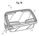
- FIG. 1 bis a perspective side view of an embodiment of a container incorporating the present invention where the tamper-evident structure indicates that the container has been opened or otherwise tampered with.
- FIG. 2is a top perspective view of the container of FIG. 1 a or 1 b with the container lid removed.
- FIG. 3is a bottom perspective view of the container of FIG. 1 a or 1 b.
- FIG. 4is an enlarged perspective view of the tamper-evident structure of the container of FIG. 1 a or 1 b.
- FIG. 5is a top perspective view of the lid of the container of FIG. 1 a or 1 b.
- FIG. 6is an enlarged perspective view of the tamper-evident structure of the lid of the container of FIG. 1 a or 1 b.
- FIG. 7is an enlarged perspective view of a tamper-evident structure according to an embodiment of the present application.
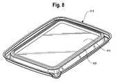
- FIG. 8is a perspective view of a lid according to an embodiment of the present application.
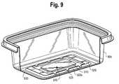
- FIG. 9is a broken perspective view of a body according to an embodiment of the present application.
- the present inventionis described as being a container food or other perishable items, it will be appreciates that the container and tamper-evident structure of the present invention can be used to store any type of item without departing from the spirit and scope of the present application.
- the present inventionrelates to a container having a tamper-evident structure adapted to indicate whether the container was previously opened or otherwise tampered with.
- the containercan include a lid releasably coupled to a body, wherein the lid is snap-it into a recess of the body. Based on the structure of the body and lid, the lid cannot be removed from the body without activating the tamper-evident structure.
- the tamper-evident structurecan remain partially attached to the lid or body to indicate whether the container was opened or otherwise tampered with.
- a container 100having a body 105 and a lid 110 adapted to be releasably coupled to the body 105 .
- a tamper-evident structure 115is provided on a corner of the body 105 and lid 110 , which allows the lid 110 to be removed from the body 105 subsequent to activation of the tamper-evident structure 115 .
- the container 100 shown in FIG. 1 ahas not been opened or otherwise tampered with wherein the lid 110 is releasably coupled to the body 105 , and thus the tamper-evident structure 115 is fully attached to the body 105 and has not been activated.
- the container 100 of FIG. 1 bshows the tamper-evident structure of the present invention activated to indicate that the container 100 has been opened or otherwise tampered with.
- FIG. 2shows a body 105 of the container 100 with the lid 110 decoupled from the body 105 .
- the body 105includes four upstanding walls 205 , e.g. one at its front, rear, left and right sides, and a bottom 210 , thereby defining a cavity 215 where contents can be placed.
- any shape containercan be used, such as, for example, square or circular, without departing from the scope and sprint of the present application.
- the bottom 210is shown as being substantially perpendicular to the walls 205 at rounded transitions thereof. However, the bottom 210 can engage the wall 205 at an angle, can be rounded relative to the walls 205 , or can engage the wall 205 at sharp corners, rather than the rounded corner shown in FIGS. 2 and 3 .
- a peripheral lip 220can be provided on the peripheral edge of the body 105 and is adapted to cooperate with the lid 110 to releasably couple the lid 110 to the body 105 .
- a ledge 225extends outwardly from the lip 220 to provide additional structural stability.
- the lip 220is adapted to matingly engage the lid 110 , such as in a snap-lock fashion, to substantially enclose the cavity 215 .
- the lid 110is not placed over the lip 220 , but the lid 110 is placed inside the cavity 215 and engages with an engagement lip 243 that extends inwardly relative to the walls 205 and extends around the periphery of the body 105 .
- the lid 110can thus releasably engage the body 105 by elastically deforming and being pushed across the engagement lip 243 , as discussed below, thereby sealing the contents in the container 100 .
- a body corner 230can be provided to matingly engage with a corner of the lid 110 to thereby define a tamper-evident structure 115 , as described below.
- the body corner 230can be attached to one or more grips 235 by way of perforated or scored edge 250 that is adapted to be broken upon partial or full decoupling of the lid 110 from the body 105 .
- the body cornercan extend from a first peripheral edge to a second peripheral edge, and can have a body corner perimeter extending around a perimeter of the body corner 230 .
- the lid 110can snap-fit into the body 105 and is recessed within the body 105 when coupled thereto. In this fashion, the lid 110 can be difficult, if not impossible, to remove from the body 105 without first lifting upward on some portion of the lid 110 . Accordingly, a user is forced to first break the tamper-evident structure 115 along edge 250 in order to access the corner of the lid 110 to partially or fully decouple the lid 110 from the body 105 for the first time. Such breakage indicates that the container 100 has previously been opened or otherwise tampered with.
- the lid 110can still be releasably coupled to the body 105 for continued use. So, for example, if a user purchases strawberries in the container 100 , the user can ensure that the strawberries were not tampered with via the tamper-evident structure 115 .
- the userUpon first opening the container 100 by removing the lid 110 from the body 105 , the user must activate the tamper-evident structure 115 to access the corner of the lid 110 . After activation, the user can still continue to releasably couple the lid 110 to the body 105 for continued use.
- the walls 205are four in number so that the container 100 forms a rectangular cavity.
- the number of walls 205is not limited, and the body 105 may include three walls 205 to provide a triangular shape, or may include six walls 205 to provide a hexagonal shape.
- the body 105could also be circular, oval, or otherwise round. Additional walls can also be included internal to the cavity to provide compartments therein. Any other number of walls 205 or shape of body 105 can be used without departing from the spirit and scope of the present application.
- the bottom 210is shown as being substantially perpendicular to the walls 205 at rounded transitions thereof. However, the bottom 210 can engage the wall 205 at an angle, can be rounded relative to the walls 205 , or can engage the wall 205 at sharp corners, rather than the rounded corner shown in FIGS. 2 and 3 .
- the lip 220is adapted to matingly engage the lid 110 , such as in a snap-lock fashion, to substantially enclose the cavity 215 .
- the lid 110is not placed over the lip 220 , but the lid 110 is placed inside the cavity 215 and engages with an engagement lip 243 that extends inwardly relative to the walls 205 and extends around the periphery of the body 105 .
- the lid 110can thus releasably engage the body 105 by elastically deforming and being pushed across the engagement lip 243 , as discussed below, thereby sealing the contents in the container 100 .
- the container 100includes vents 244 on the lid 110 and/or body 105 to allow air into and out of the container 100 .
- the vents 244are advantageous for foods that emit gasses after being stored in a container or otherwise require a “breathable” container. Gas can also be trapped in the container 100 when closing the lid 110 to the body 105 .
- the vents 244allow such gas to escape without creating excessive internal pressure in the container 100 .
- the number, size and shape of vents 244can vary within the spirit and scope of the invention.
- the ledge 225is an outwardly extending portion of the lip 220 , where the user can insert underneath the lip 220 to better grip the lid 110 . As shown, the ledge 225 extends circumferentially around the lip 220 , except for portions adjacent the body corner 230 . However, the length and distribution of the ledge 225 can be more or less than that shown in the figures, or can be non-uniformly distributed around the lip 220 , without departing from the spirit and scope of the present application.
- the outside of the bottom 210can include protrusions 240 , such as feet, outwardly extending from the bottom 210 of the container 100 to provide an elevated surface of the bottom 210 relative to a ground plane.
- the protrusions 240help raise the container 100 above the ground plane by providing objects on the bottom 210 of the body 105 .
- any variation of the protrusions 240can be used to raise the container 100 from the ground plane.
- the protrusions 240can be a continuous rail that extends adjacent an outer periphery of the container 100 rather than having discontinuous protrusions 240 , as shown in FIG. 3 .
- a center protrusioncan be provided to raise the container 100 from the ground plane, either independently from or in combination with the feet 240 .
- the center protrusioncan also be applied in combination with a rail that extends around the periphery of the bottom 210 of the container 100 .
- the protrusions 240allow stacking of a plurality of containers 100 .
- protrusions 240can be omitted.
- FIG. 4illustrates a body corner 230 including an embodiment of the tamper-evident structure 115 of the present invention.
- the body corner 230includes a deformable tab 245 that is adapted to be gripped with fingers to pull the tamper-evident structure 115 downwardly and activate it by breaking the tamper-evident structure 115 along perforated edges 250 , allowing a user to access the corner of the lid 110 to remove, either partially or completely, the lid 110 from the body 105 to access the contents in the container 100 .
- the lid 110is difficult or impossible to remove without first activating the tamper-evident structure 115 .
- the tab 245may be substantially L-shaped, with a rounded corner connecting two straight portions.
- the tab 245can be circular, rectangular, or can be any other shape that allows a user to grip the tamper-evident structure 115 and activate it.
- the body corner 230is coupled to the grip 235 by way of partially perforated edges 250 .
- the perforated edges 250allow the user to decouple the body corner 230 from the remainder of the body 105 with relative ease to allow access to a corner of the lid 110 , while still connecting the grip 235 to the corner 230 after activation of the tamper-evident structure 115 .
- the perforated edges 250connect the body corner 230 to two grips 235 , and can also connect the body corner 230 to the body 105 adjacent the hinge 255 .
- the location of the perforated edges 250can be helpful in achieving the goal of disallowing user entry into the container 100 without activating the tamper-evident structure 115 .
- the perforated edges 250can include two discrete connections between the body corner 230 and the grips 235 , the connections being at the most outward peripheral points of the container 100 , i.e., between the “GRIP” and “PULL DOWN” labels in FIGS. 2 and 4 . In this manner, the perforated edges 250 must be broken to pull downwardly on the body corner 230 to release the lid 110 from the body 105 .
- the hinge 255is a portion that couples the body corner 230 to the body 105 .
- the hinge 255can include an elastomeric or deformable interface and may include perforated edges surrounding the interface that couple the body corner 230 to the remainder of the body 105 .
- the hinge 255includes one or more smooth, discontinuous edges adjacent the hinge 255 . As shown, the hinge 255 allows the tamper-evident structure 115 to be activated, but the body corner 230 still remains coupled to the body 105 at the hinge 255 .
- the tamper-evident structure 115is activated, because although the contents of the container 100 can be obtained after the tamper-evident structure 115 is activated, the body corner 230 remains partially coupled to the body 105 by way of the hinge 255 , to alert the user that the tamper-evident structure 115 has been activated.
- the body corner 230may include a ramp 260 aligned in the direction of the user-applied diagonal and downward force to activate the tamper-evident structure 115 .
- the ramp 260is angled in substantially the same direction that a user is likely to apply a force to activate the tamper-evident structure 115 .
- the lid 110includes a peripheral flange 305 extending around the outer peripheral edge of the lid 110 , and a trough 310 extending from the flange 305 and coupled to a stiffening ledge 315 provided at an inward peripheral portion of the lid 110 .
- the lid 110also includes raised portions 320 adapted to allow the user to grip the lid 110 when the lid 110 has been removed from the body 105 .
- the lid 110also includes a lid corner 325 that can rest in or engage the body corner 230 to collectively form the tamper-evident structure 115 with the body corner 230 .
- the trough 310 of the lid 110extends downwardly and can engage the engagement lip 243 of the body 105 so that the lid 110 is removably coupled to the body 105 .
- the trough 310can elastically deform by way of an open space inside the trough 310 so that the engagement lip 243 of the body 105 pinches the trough 310 when the lid 110 engages with the engagement lip 243 .
- the flange 305prevents the lid 110 from being inserted too far into the body 105 by providing an extending surface that rests on top of the engagement lip 243 and resists movement of the lid 110 into the body 105 .
- the trough 310can include a peripheral groove adapted to matingly engage the engagement lip 243 and better secure the lid 110 to the body 105 .
- the stiffening ledge 315can be a rounded peripheral extending portion that provides additional stiffness to the lid 110 and suppresses flexing of the lid 110 .
- the stiffening ledge 315can extend around the periphery of the lid 110 slightly inwardly from the trough 310 , and can form an inner boundary of the trough 310 .
- the stiffening ledge 315is rounded at its boundary with the trough 310 , and in combination with the trough 310 , makes removing the lid 110 difficult or nearly impossible without first activating the tamper-evident structure 115 and pulling on the lid corner 325 .
- the stiffening ledge 315resists the inward force of fingers (or other gripping means) on the lid 110 to disallow flexing of the lid 110 and removal of the lid 110 from the body 105 without activating the tamper-evident structure 115 .
- the lid corner 325includes a perimeter 330 that allows a user to grip the tamper-evident structure 115 , similar to the tab 245 of the body corner 230 .
- the lid corner 325is coupled to the lid 110 by interface 335 .
- the lid corner 325includes ribs 340 that provide additional structural support for the lid corner 325 and suppress bending of the lid corner 325 .
- the perimeter 330can be any shape that allows a user to grip the lid corner 325 and activate the tamper-evident structure 115 .
- the perimeter 330is semicircular or semielliptical.
- the perimeter 330can be partially or fully rectangular, triangular, circular, or any other shape that allows a user to grip the lid corner 325 and activate the tamper-evident structure 115 .
- the perimeter 330is a shape similar to that of the tab 245 to allow better fitting between the lid corner 325 and the body corner 230 .
- the perimeter 330can be placed above the tab 245 and can be received within the tab 245 such that pulling downwardly on perimeter 330 also pulls downwardly on the tab 245 .
- the interface 335can be a rigid structure that couples the lid corner 325 to the remainder of the lid 110 .
- the interface 335can be a rigid connection to require a force to pull down on the lid corner 325 and break the perforated edges 250 of the body corner 230 .
- the ribs 340also strengthen the interface 335 between the lid corner 325 and the remainder of the lid 110 to require additional force to activate the tamper-evident structure 115 . Based on this additional strength, a user is not likely to accidentally activate the tamper-evident structure 115 , because a purposeful amount of force is required to activate the tamper-evident structure 115 .
- the additional strength of the interface 335is also helpful for when a user wishes to remove the lid 110 after activating the tamper-evident structure 115 .
- the useris required to pull upwardly on the lid corner 325 and disengage the trough 310 from the engagement lip 243 .
- the lid corner 325it is helpful for the lid corner 325 to have a substantial amount of strength for the purposes of durability, knowing that a user is likely to apply stress on the lid corner 325 upon each removal of the lid 110 .
- the shape of the lid corner 325can be any shape that allows a user to lift the lid 110 and remove it from the body 105 .
- the lid corner 325is coupled to or integral with the trough 310 and helps cover the cavity 215 of the body 105 to protect the contents therein. In this manner, even though the tamper-evident structure 115 is activated, the container 100 can be reused and the lid 110 can be releasably coupled to the body 105 and the contents of the container 100 can still be protected from outside elements.
- FIG. 7illustrates a tamper-evident structure 715 according to another embodiment of the present application.
- the tamper-evident structure 715can include a ledge 225 , body corner 730 , grip 735 , tab 745 , perforated edges 750 , and ramp portion 760 , similar to the tamper-evident structure shown in FIG. 4 .
- the tamper-evident structure 715 of FIG. 7differs from that shown in FIG. 4 by reducing the width of the ledge 725 located on the periphery of the container 100 , or increasing the width of the ledge 725 in areas other than the tamper-evident structure 715 .
- the ledge 225is generally uniform around the container 100 and does not increase in width at the tamper-evident structure 715 , like the structure 115 shown in FIG. 4 .
- the term “PULL DOWN”can be located on a vertical face of the body corner 730 rather than the grip 735 .
- Other modifications similar to those discussed abovecan be implemented without departing from the spirit and scope of the present application.
- FIG. 8illustrates a lid 810 according to another embodiment of the present application.
- the lid 810includes structure that allows stacking of one or more containers 100 .
- the lid 810includes a stacking surface 815 with a perimeter 820 .
- the stacking surface 815 and perimeter 820are sized such that a bottom of a container 100 can be placed on the stacking surface 815 and within the interior of the perimeter 820 .
- the perimeter 820may be raised to inhibit lateral movement of a stacked container 100 .
- FIG. 9illustrates another embodiment of the body 905 with a liquid-retaining reservoir 910 provided on a bottom surface of the body 905 .
- the liquid-retaining reservoir 910can retain liquids, such as juices or water from produce, in the bottom of the body 905 and keep the contents of the container 100 from being submerged in the liquid. For example, if strawberries are held in the container 100 , the liquid-retaining reservoir 910 can prevent the strawberries from soaking in their own juices and better preserve the strawberries.
- the liquid-retaining reservoir 910includes a platform 915 with a perimeter 920 .
- the perimeter 920can be continuous or, if discontinuous, can include segments 920 A separated by gaps 925 .
- a channel 930is disposed lower than the raised platform 915 and perimeter 920 to collect any liquids that may be in the container 100 .
- the container 100is a closed container with no holes or vents provided in any of the components.
- the container 100can include holes or cavities provided in any of the components, for example, the body 105 or the lid 110 , to provide ventilation for the contents of the container 100 , without departing from the spirit and scope of the present application.
- the container 100is made of a plastic.
- the container 100 or individual componentscan be made of any material.
- a process for activating the tamper-evident structure 115 and removing the lid 110 from the body 105will now be discussed.
- a usercan grip with their fingers the perimeter 330 of the lid 110 and pull downwardly on the perimeter 330 to break the perforated edges 250 of the body corner 230 , thereby activating the tamper-evident structure 115 .
- the body corner 230remains coupled to the body 105 by way of the hinge 255 .
- a usercan be aware that the tamper-evident structure 115 has been activated and the container 100 was previously opened.
- a usercan remove the lid 110 , partially or fully, from body 105 by pulling upwardly on, for example, the lid corner 325 , which is rigidly coupled to or integrally formed with the remainder of the lid 110 by way of interface 335 .
- the intersection between the raised portion 320 and the trough 310can provide a gripping portion for the user to grip and move the lid 110 away from or towards the body 105 after the tamper-evident structure 115 is activated and the lid 110 disengaged from the body 105 .
- the tamper-evident structure 115is located on a corner of the container 100 .
- the tamper-evident structure 115can be located at any portion of the container 100 , for example, around the periphery of a circular container, or along an edge of a polygonal container. Any location of the tamper-evident structure 115 can be implemented without departing from the spirit and scope of the present invention.
Landscapes
- Engineering & Computer Science (AREA)
- Mechanical Engineering (AREA)
- Closures For Containers (AREA)
Abstract
Description
Claims (11)
Priority Applications (4)
| Application Number | Priority Date | Filing Date | Title |
|---|---|---|---|
| US13/545,179US8684212B2 (en) | 2011-07-18 | 2012-07-10 | Tamper-evident container that indicates when the container has been tampered with or opened |
| CA2840442ACA2840442A1 (en) | 2011-07-18 | 2012-07-11 | Tamper-evident container |
| PCT/US2012/046184WO2013012630A1 (en) | 2011-07-18 | 2012-07-11 | Tamper-evident container |
| US14/230,754US9315302B2 (en) | 2011-07-18 | 2014-03-31 | Tamper-evident container that indicates when the container has been tampered with or opened |
Applications Claiming Priority (2)
| Application Number | Priority Date | Filing Date | Title |
|---|---|---|---|
| US201161508933P | 2011-07-18 | 2011-07-18 | |
| US13/545,179US8684212B2 (en) | 2011-07-18 | 2012-07-10 | Tamper-evident container that indicates when the container has been tampered with or opened |
Related Child Applications (1)
| Application Number | Title | Priority Date | Filing Date |
|---|---|---|---|
| US14/230,754ContinuationUS9315302B2 (en) | 2011-07-18 | 2014-03-31 | Tamper-evident container that indicates when the container has been tampered with or opened |
Publications (2)
| Publication Number | Publication Date |
|---|---|
| US20130020325A1 US20130020325A1 (en) | 2013-01-24 |
| US8684212B2true US8684212B2 (en) | 2014-04-01 |
Family
ID=47555076
Family Applications (2)
| Application Number | Title | Priority Date | Filing Date |
|---|---|---|---|
| US13/545,179Active - ReinstatedUS8684212B2 (en) | 2011-07-18 | 2012-07-10 | Tamper-evident container that indicates when the container has been tampered with or opened |
| US14/230,754ActiveUS9315302B2 (en) | 2011-07-18 | 2014-03-31 | Tamper-evident container that indicates when the container has been tampered with or opened |
Family Applications After (1)
| Application Number | Title | Priority Date | Filing Date |
|---|---|---|---|
| US14/230,754ActiveUS9315302B2 (en) | 2011-07-18 | 2014-03-31 | Tamper-evident container that indicates when the container has been tampered with or opened |
Country Status (3)
| Country | Link |
|---|---|
| US (2) | US8684212B2 (en) |
| CA (1) | CA2840442A1 (en) |
| WO (1) | WO2013012630A1 (en) |
Cited By (9)
| Publication number | Priority date | Publication date | Assignee | Title |
|---|---|---|---|---|
| US20150136777A1 (en)* | 2013-11-21 | 2015-05-21 | Placon Corporation | Trapped Element Security Container |
| US9278786B2 (en) | 2011-03-22 | 2016-03-08 | Smart-Tab, Llc | Containers with tamper-evident features |
| US9333289B1 (en) | 2015-01-16 | 2016-05-10 | Plas-Tech Engineering, Inc. | Tamper evident closure container |
| US9527640B2 (en) | 2003-07-21 | 2016-12-27 | Inline Plastics Corp. | Methods of manufacturing tamper-resistant and tamper evident containers |
| US9643761B1 (en) | 2015-12-08 | 2017-05-09 | Inline Plastics Corp. | Child-resistant containers |
| USD786666S1 (en) | 2013-09-13 | 2017-05-16 | State Garden, Inc. | Container with butterfly lid closure |
| US9926118B2 (en) | 2015-12-08 | 2018-03-27 | Inline Plastics Corp. | Child-resistant containers |
| US10384843B2 (en) | 2017-01-31 | 2019-08-20 | Smart-Tab, Llc | Pull-tab tamper evident container |
| US11505373B2 (en) | 2020-01-31 | 2022-11-22 | Greener Shapes Inc. | Receptacle having a tamper resistant locking mechanism for produce and foodstuff |
Families Citing this family (24)
| Publication number | Priority date | Publication date | Assignee | Title |
|---|---|---|---|---|
| CA2748798C (en)* | 2011-08-16 | 2018-09-25 | Bn Progressive Products Ltd. | Tamper-evident container |
| AU2013354828A1 (en)* | 2012-12-07 | 2015-07-09 | 2266170 Ontario Inc. | Container with removable portion |
| US9187209B1 (en)* | 2013-07-05 | 2015-11-17 | Highland Packaging Solutions, Inc. | Tamper evident container having tear tab and hinged lid |
| US9561885B1 (en)* | 2013-09-27 | 2017-02-07 | Plastic Ingenuity, Inc. | Tamper resistant container |
| JP6198318B2 (en)* | 2013-10-30 | 2017-09-20 | 株式会社エフピコ | Inner mating packaging container with tamper-proof structure |
| USD742222S1 (en) | 2013-11-27 | 2015-11-03 | Scott P. Liu | Packaging device |
| USD742218S1 (en)* | 2014-03-20 | 2015-11-03 | Peninsula Packaging Company, Llc | Container |
| US20160101907A1 (en)* | 2014-10-09 | 2016-04-14 | Display Pack, Inc. | Tamper-evident tab thermoformed packaging |
| US9981782B2 (en) | 2015-06-04 | 2018-05-29 | Sabert Corporation | Tamper-evident container and method |
| US9944436B2 (en) | 2015-12-14 | 2018-04-17 | Sabert Corporation | Tamper-evident container and method |
| US10669078B2 (en) | 2015-12-14 | 2020-06-02 | Sabert Corporation | Tamper-evident container and method |
| JP6573247B2 (en)* | 2016-03-10 | 2019-09-11 | パナソニックIpマネジメント株式会社 | Flying object |
| USD854380S1 (en)* | 2016-05-11 | 2019-07-23 | Zhejiang Xueli Commodity Co., Ltd | Container |
| US10906709B2 (en)* | 2016-12-21 | 2021-02-02 | Pactiv LLC | Systems and methods for containers with locking lug and recess |
| US10723523B2 (en) | 2017-01-10 | 2020-07-28 | Fabri-Kal Corporation | Tamper evident container having bonded tab |
| USD934635S1 (en)* | 2017-02-09 | 2021-11-02 | The Decor Corporation Pty Ltd. | Container base |
| US10279962B2 (en) | 2017-03-21 | 2019-05-07 | Display Pack, Inc. | Tamper-evident thermoformed packaging |
| USD901255S1 (en)* | 2017-12-07 | 2020-11-10 | The Decor Corporation Pty Ltd. | Container base |
| USD949684S1 (en) | 2019-01-11 | 2022-04-26 | Genpak, Llc | Tamper-evident hinge for a food container |
| US11628981B2 (en) | 2020-01-24 | 2023-04-18 | Pianca Packaging Llc | Tamper evident container |
| USD983669S1 (en)* | 2020-06-23 | 2023-04-18 | Carla Morrison Fine Jewelry | Wipe container |
| US11535428B2 (en) | 2020-07-16 | 2022-12-27 | Placon Corporation | Tamper evident reclosable container |
| US11794966B2 (en) | 2021-12-06 | 2023-10-24 | Tekni-Plex, Inc. | Food container with tamper-proof hinged closure |
| US20250083877A1 (en)* | 2023-09-12 | 2025-03-13 | D&W Fine Pack | Food Container with Access Tab |
Citations (15)
| Publication number | Priority date | Publication date | Assignee | Title |
|---|---|---|---|---|
| US3580473A (en) | 1969-02-06 | 1971-05-25 | Lester D Gill | Paper board container with platform style bottom |
| US6032827A (en)* | 1998-06-25 | 2000-03-07 | S. C. Johnson Home Storage, Inc. | Container having a selectively detachable lid including a rigid tab member |
| USD448991S1 (en)* | 2000-08-10 | 2001-10-09 | S. C. Johnson Home Storage, Inc. | Container |
| US6971539B1 (en) | 2001-04-27 | 2005-12-06 | Saber-Com, Inc. | Apparatus for storing food |
| US20070045317A1 (en)* | 2005-08-31 | 2007-03-01 | Rosender Adam K | Tamper evident thermoformed containers |
| US20070138180A1 (en)* | 2005-12-21 | 2007-06-21 | Terry Vovan | Enhanced tamper evident bowl with blocked tab |
| US20090120937A1 (en)* | 2007-11-10 | 2009-05-14 | Terry Vovan | Double ribbed secure container |
| US20090206082A1 (en)* | 2008-02-14 | 2009-08-20 | Pwp Industries | Tamper-evident packaging system |
| US20100051620A1 (en)* | 2008-08-29 | 2010-03-04 | Parikh Samir R | Tamper-evident container |
| US20100084401A1 (en)* | 2008-01-08 | 2010-04-08 | Golota George A | Tamper evident container |
| US20100276422A1 (en)* | 2009-04-29 | 2010-11-04 | Terry Vovan | Enhanced secure container |
| US20110031246A1 (en) | 2009-08-07 | 2011-02-10 | Massey Jr Raymond C | Tamper-Resistant Storage Container |
| US7913870B2 (en) | 2005-05-10 | 2011-03-29 | Pactiv Corporation | Tamper evident container |
| US20120005994A1 (en)* | 2010-07-09 | 2012-01-12 | Display Pack, Inc. | Thermoformed package with tamper evident seal |
| US20120292322A1 (en)* | 2011-05-19 | 2012-11-22 | Display Pack, Inc. | Tamper-evident tab arrangement for thermoformed package |
- 2012
- 2012-07-10USUS13/545,179patent/US8684212B2/enactiveActive - Reinstated
- 2012-07-11CACA2840442Apatent/CA2840442A1/ennot_activeAbandoned
- 2012-07-11WOPCT/US2012/046184patent/WO2013012630A1/enactiveApplication Filing
- 2014
- 2014-03-31USUS14/230,754patent/US9315302B2/enactiveActive
Patent Citations (15)
| Publication number | Priority date | Publication date | Assignee | Title |
|---|---|---|---|---|
| US3580473A (en) | 1969-02-06 | 1971-05-25 | Lester D Gill | Paper board container with platform style bottom |
| US6032827A (en)* | 1998-06-25 | 2000-03-07 | S. C. Johnson Home Storage, Inc. | Container having a selectively detachable lid including a rigid tab member |
| USD448991S1 (en)* | 2000-08-10 | 2001-10-09 | S. C. Johnson Home Storage, Inc. | Container |
| US6971539B1 (en) | 2001-04-27 | 2005-12-06 | Saber-Com, Inc. | Apparatus for storing food |
| US7913870B2 (en) | 2005-05-10 | 2011-03-29 | Pactiv Corporation | Tamper evident container |
| US20070045317A1 (en)* | 2005-08-31 | 2007-03-01 | Rosender Adam K | Tamper evident thermoformed containers |
| US20070138180A1 (en)* | 2005-12-21 | 2007-06-21 | Terry Vovan | Enhanced tamper evident bowl with blocked tab |
| US20090120937A1 (en)* | 2007-11-10 | 2009-05-14 | Terry Vovan | Double ribbed secure container |
| US20100084401A1 (en)* | 2008-01-08 | 2010-04-08 | Golota George A | Tamper evident container |
| US20090206082A1 (en)* | 2008-02-14 | 2009-08-20 | Pwp Industries | Tamper-evident packaging system |
| US20100051620A1 (en)* | 2008-08-29 | 2010-03-04 | Parikh Samir R | Tamper-evident container |
| US20100276422A1 (en)* | 2009-04-29 | 2010-11-04 | Terry Vovan | Enhanced secure container |
| US20110031246A1 (en) | 2009-08-07 | 2011-02-10 | Massey Jr Raymond C | Tamper-Resistant Storage Container |
| US20120005994A1 (en)* | 2010-07-09 | 2012-01-12 | Display Pack, Inc. | Thermoformed package with tamper evident seal |
| US20120292322A1 (en)* | 2011-05-19 | 2012-11-22 | Display Pack, Inc. | Tamper-evident tab arrangement for thermoformed package |
Non-Patent Citations (2)
| Title |
|---|
| International Search Report, Int'l Application No. PCT/US2012/046184, dated Sep. 14, 2012; 2 pages. |
| Written Opinion of the International Search Authority, Int'l Application No. PCT/US2012/046184, dated Sep. 14, 2012; 19 pages. |
Cited By (18)
| Publication number | Priority date | Publication date | Assignee | Title |
|---|---|---|---|---|
| US11530079B2 (en) | 2003-07-21 | 2022-12-20 | Inline Plastics Corp. | Tamper-resistant and tamper-evident containers |
| US9527640B2 (en) | 2003-07-21 | 2016-12-27 | Inline Plastics Corp. | Methods of manufacturing tamper-resistant and tamper evident containers |
| US9630756B2 (en) | 2003-07-21 | 2017-04-25 | Inline Plastics Corp. | Tamper-resistant and tamper evident containers |
| US9278786B2 (en) | 2011-03-22 | 2016-03-08 | Smart-Tab, Llc | Containers with tamper-evident features |
| USD786666S1 (en) | 2013-09-13 | 2017-05-16 | State Garden, Inc. | Container with butterfly lid closure |
| US9352886B2 (en)* | 2013-11-21 | 2016-05-31 | Placon Corporation | Trapped element security container |
| US20150136777A1 (en)* | 2013-11-21 | 2015-05-21 | Placon Corporation | Trapped Element Security Container |
| US11357908B2 (en) | 2015-01-16 | 2022-06-14 | Plas-Tech Engineering, Inc. | Tamper evident closure container |
| US10342914B2 (en) | 2015-01-16 | 2019-07-09 | Plas-Tech Engineering, Inc. | Tamper evident closure container |
| US9333289B1 (en) | 2015-01-16 | 2016-05-10 | Plas-Tech Engineering, Inc. | Tamper evident closure container |
| US11541164B2 (en) | 2015-01-16 | 2023-01-03 | Plas-Tech Engineering, Inc. | Tamper evident closure container |
| US11857754B2 (en) | 2015-01-16 | 2024-01-02 | Plas-Tech Engineering, Inc. | Tamper evident closure container |
| US12121694B2 (en) | 2015-01-16 | 2024-10-22 | Plas-Tech Engineering, Inc. | Tamper evident closure container |
| US9926118B2 (en) | 2015-12-08 | 2018-03-27 | Inline Plastics Corp. | Child-resistant containers |
| US10543967B2 (en) | 2015-12-08 | 2020-01-28 | Inline Plastics Corp. | Child-resistant containers |
| US9643761B1 (en) | 2015-12-08 | 2017-05-09 | Inline Plastics Corp. | Child-resistant containers |
| US10384843B2 (en) | 2017-01-31 | 2019-08-20 | Smart-Tab, Llc | Pull-tab tamper evident container |
| US11505373B2 (en) | 2020-01-31 | 2022-11-22 | Greener Shapes Inc. | Receptacle having a tamper resistant locking mechanism for produce and foodstuff |
Also Published As
| Publication number | Publication date |
|---|---|
| WO2013012630A1 (en) | 2013-01-24 |
| US20130020325A1 (en) | 2013-01-24 |
| US9315302B2 (en) | 2016-04-19 |
| CA2840442A1 (en) | 2013-01-24 |
| US20140209609A1 (en) | 2014-07-31 |
Similar Documents
| Publication | Publication Date | Title |
|---|---|---|
| US9315302B2 (en) | Tamper-evident container that indicates when the container has been tampered with or opened | |
| CA2565256C (en) | Enhanced tamper evident bowl with blocked tab | |
| US7938286B2 (en) | Container system | |
| US7694845B2 (en) | Removable and reclosable lid for jar for a food product | |
| US8157123B2 (en) | Container | |
| US10597193B2 (en) | Container with removable tray | |
| KR102411101B1 (en) | Anti-opening vent box | |
| US12227350B2 (en) | Ventilated container for produce | |
| US20120292323A1 (en) | Tamper evident lid for a container | |
| US20090039051A1 (en) | Molded Plastic Container Assembly With Tear Strip | |
| US10759571B2 (en) | Container for produce storage, packing and transport | |
| AU2020200458B2 (en) | Ventilated container for produce | |
| US20200172300A1 (en) | Tray with re-closeable lid | |
| EP1736417B1 (en) | Tamper evident bowl with blocked tab | |
| CA2961309C (en) | Cover for a container | |
| EP3494067B1 (en) | Ventilated container for produce |
Legal Events
| Date | Code | Title | Description |
|---|---|---|---|
| AS | Assignment | Owner name:WELLS FARGO BANK, NATIONAL ASSOCIATION, ILLINOIS Free format text:SECURITY INTEREST;ASSIGNORS:D&W FINE PACK HOLDINGS LLC;D&W FINE PACK LLC;REEL/FRAME:034861/0938 Effective date:20150115 | |
| AS | Assignment | Owner name:D&W FINE PACK, INDIANA Free format text:ASSIGNMENT OF ASSIGNORS INTEREST;ASSIGNORS:D&W FINE PACK;STONE, JOSEPH;JIMENEZ, GREGORY;AND OTHERS;SIGNING DATES FROM 20060714 TO 20140702;REEL/FRAME:035200/0005 | |
| FEPP | Fee payment procedure | Free format text:MAINTENANCE FEE REMINDER MAILED (ORIGINAL EVENT CODE: REM.) | |
| LAPS | Lapse for failure to pay maintenance fees | Free format text:PATENT EXPIRED FOR FAILURE TO PAY MAINTENANCE FEES (ORIGINAL EVENT CODE: EXP.) | |
| PRDP | Patent reinstated due to the acceptance of a late maintenance fee | Effective date:20180515 | |
| FEPP | Fee payment procedure | Free format text:PETITION RELATED TO MAINTENANCE FEES GRANTED (ORIGINAL EVENT CODE: PMFG) Free format text:PETITION RELATED TO MAINTENANCE FEES FILED (ORIGINAL EVENT CODE: PMFP) Free format text:SURCHARGE, PETITION TO ACCEPT PYMT AFTER EXP, UNINTENTIONAL (ORIGINAL EVENT CODE: M1558) | |
| MAFP | Maintenance fee payment | Free format text:PAYMENT OF MAINTENANCE FEE, 4TH YEAR, LARGE ENTITY (ORIGINAL EVENT CODE: M1551) Year of fee payment:4 | |
| STCF | Information on status: patent grant | Free format text:PATENTED CASE | |
| FP | Lapsed due to failure to pay maintenance fee | Effective date:20180401 | |
| AS | Assignment | Owner name:CALLODINE COMMERCIAL FINANCE, LLC, AS AGENT, MASSACHUSETTS Free format text:SECURITY INTEREST;ASSIGNOR:D&W FINE PACK LLC;REEL/FRAME:054884/0185 Effective date:20201231 | |
| AS | Assignment | Owner name:D&W FINE PACK LLC, ILLINOIS Free format text:RELEASE BY SECURED PARTY;ASSIGNOR:WELLS FARGO BANK, NATIONAL ASSOCIATION;REEL/FRAME:054888/0309 Effective date:20201231 Owner name:D&W FINE PACK HOLDINGS LLC, ILLINOIS Free format text:RELEASE BY SECURED PARTY;ASSIGNOR:WELLS FARGO BANK, NATIONAL ASSOCIATION;REEL/FRAME:054888/0309 Effective date:20201231 | |
| AS | Assignment | Owner name:ENCINA BUSINESS CREDIT, LLC, ILLINOIS Free format text:SECURITY INTEREST;ASSIGNOR:D&W FINE PACK LLC;REEL/FRAME:055307/0681 Effective date:20201231 | |
| FEPP | Fee payment procedure | Free format text:MAINTENANCE FEE REMINDER MAILED (ORIGINAL EVENT CODE: REM.); ENTITY STATUS OF PATENT OWNER: LARGE ENTITY | |
| LAPS | Lapse for failure to pay maintenance fees | Free format text:PATENT EXPIRED FOR FAILURE TO PAY MAINTENANCE FEES (ORIGINAL EVENT CODE: EXP.); ENTITY STATUS OF PATENT OWNER: LARGE ENTITY | |
| STCH | Information on status: patent discontinuation | Free format text:PATENT EXPIRED DUE TO NONPAYMENT OF MAINTENANCE FEES UNDER 37 CFR 1.362 | |
| PRDP | Patent reinstated due to the acceptance of a late maintenance fee | Effective date:20220519 | |
| FEPP | Fee payment procedure | Free format text:PETITION RELATED TO MAINTENANCE FEES FILED (ORIGINAL EVENT CODE: PMFP); ENTITY STATUS OF PATENT OWNER: LARGE ENTITY Free format text:PETITION RELATED TO MAINTENANCE FEES GRANTED (ORIGINAL EVENT CODE: PMFG); ENTITY STATUS OF PATENT OWNER: LARGE ENTITY Free format text:SURCHARGE, PETITION TO ACCEPT PYMT AFTER EXP, UNINTENTIONAL (ORIGINAL EVENT CODE: M1558); ENTITY STATUS OF PATENT OWNER: LARGE ENTITY | |
| MAFP | Maintenance fee payment | Free format text:PAYMENT OF MAINTENANCE FEE, 8TH YEAR, LARGE ENTITY (ORIGINAL EVENT CODE: M1552); ENTITY STATUS OF PATENT OWNER: LARGE ENTITY Year of fee payment:8 | |
| STCF | Information on status: patent grant | Free format text:PATENTED CASE | |
| FP | Lapsed due to failure to pay maintenance fee | Effective date:20220401 | |
| AS | Assignment | Owner name:PNC BANK, NATIONAL ASSOCIATION, PENNSYLVANIA Free format text:SECURITY INTEREST;ASSIGNOR:D&W FINE PACK LLC;REEL/FRAME:061894/0568 Effective date:20221107 | |
| MAFP | Maintenance fee payment | Free format text:PAYMENT OF MAINTENANCE FEE, 12TH YEAR, LARGE ENTITY (ORIGINAL EVENT CODE: M1553); ENTITY STATUS OF PATENT OWNER: LARGE ENTITY Year of fee payment:12 |