US8684112B2 - Cutting elements for earth-boring tools, earth-boring tools including such cutting elements and related methods - Google Patents
Cutting elements for earth-boring tools, earth-boring tools including such cutting elements and related methodsDownload PDFInfo
- Publication number
- US8684112B2 US8684112B2US13/092,396US201113092396AUS8684112B2US 8684112 B2US8684112 B2US 8684112B2US 201113092396 AUS201113092396 AUS 201113092396AUS 8684112 B2US8684112 B2US 8684112B2
- Authority
- US
- United States
- Prior art keywords
- indentation
- diamond table
- cutting element
- cutting
- sacrificial structure
- Prior art date
- Legal status (The legal status is an assumption and is not a legal conclusion. Google has not performed a legal analysis and makes no representation as to the accuracy of the status listed.)
- Active, expires
Links
Images


Classifications
- E—FIXED CONSTRUCTIONS
- E21—EARTH OR ROCK DRILLING; MINING
- E21B—EARTH OR ROCK DRILLING; OBTAINING OIL, GAS, WATER, SOLUBLE OR MELTABLE MATERIALS OR A SLURRY OF MINERALS FROM WELLS
- E21B10/00—Drill bits
- E21B10/46—Drill bits characterised by wear resisting parts, e.g. diamond inserts
- E21B10/56—Button-type inserts
- E21B10/567—Button-type inserts with preformed cutting elements mounted on a distinct support, e.g. polycrystalline inserts
- E21B10/5673—Button-type inserts with preformed cutting elements mounted on a distinct support, e.g. polycrystalline inserts having a non planar or non circular cutting face
- B—PERFORMING OPERATIONS; TRANSPORTING
- B24—GRINDING; POLISHING
- B24D—TOOLS FOR GRINDING, BUFFING OR SHARPENING
- B24D18/00—Manufacture of grinding tools or other grinding devices, e.g. wheels, not otherwise provided for
- B—PERFORMING OPERATIONS; TRANSPORTING
- B24—GRINDING; POLISHING
- B24D—TOOLS FOR GRINDING, BUFFING OR SHARPENING
- B24D99/00—Subject matter not provided for in other groups of this subclass
- B24D99/005—Segments of abrasive wheels
- E—FIXED CONSTRUCTIONS
- E21—EARTH OR ROCK DRILLING; MINING
- E21B—EARTH OR ROCK DRILLING; OBTAINING OIL, GAS, WATER, SOLUBLE OR MELTABLE MATERIALS OR A SLURRY OF MINERALS FROM WELLS
- E21B10/00—Drill bits
- E21B10/46—Drill bits characterised by wear resisting parts, e.g. diamond inserts
- E21B10/54—Drill bits characterised by wear resisting parts, e.g. diamond inserts the bit being of the rotary drag type, e.g. fork-type bits
- E21B10/55—Drill bits characterised by wear resisting parts, e.g. diamond inserts the bit being of the rotary drag type, e.g. fork-type bits with preformed cutting elements
- E—FIXED CONSTRUCTIONS
- E21—EARTH OR ROCK DRILLING; MINING
- E21B—EARTH OR ROCK DRILLING; OBTAINING OIL, GAS, WATER, SOLUBLE OR MELTABLE MATERIALS OR A SLURRY OF MINERALS FROM WELLS
- E21B10/00—Drill bits
- E21B10/46—Drill bits characterised by wear resisting parts, e.g. diamond inserts
- E21B10/56—Button-type inserts
- E21B10/567—Button-type inserts with preformed cutting elements mounted on a distinct support, e.g. polycrystalline inserts
- E21B10/573—Button-type inserts with preformed cutting elements mounted on a distinct support, e.g. polycrystalline inserts characterised by support details, e.g. the substrate construction or the interface between the substrate and the cutting element
- E21B10/5735—Interface between the substrate and the cutting element
- Y—GENERAL TAGGING OF NEW TECHNOLOGICAL DEVELOPMENTS; GENERAL TAGGING OF CROSS-SECTIONAL TECHNOLOGIES SPANNING OVER SEVERAL SECTIONS OF THE IPC; TECHNICAL SUBJECTS COVERED BY FORMER USPC CROSS-REFERENCE ART COLLECTIONS [XRACs] AND DIGESTS
- Y02—TECHNOLOGIES OR APPLICATIONS FOR MITIGATION OR ADAPTATION AGAINST CLIMATE CHANGE
- Y02E—REDUCTION OF GREENHOUSE GAS [GHG] EMISSIONS, RELATED TO ENERGY GENERATION, TRANSMISSION OR DISTRIBUTION
- Y02E10/00—Energy generation through renewable energy sources
- Y02E10/10—Geothermal energy
Definitions
- Embodiments of the present inventionrelate to earth-boring tools, cutting elements for such earth-boring tools, and related methods.
- Wellboresare formed in subterranean formations for various purposes including, for example, extraction of oil and gas from the subterranean formation and extraction of geothermal heat from the subterranean formation.
- Wellboresmay be formed in a subterranean formation using a drill bit such as, for example, an earth-boring rotary drill bit.
- a drill bitsuch as, for example, an earth-boring rotary drill bit.
- Different types of earth-boring rotary drill bitsare known in the art including, for example, fixed-cutter bits (which are often referred to in the art as “drag” bits), rolling-cutter bits (which are often referred to in the art as “rock” bits), diamond-impregnated bits, and hybrid bits (which may include, for example, both fixed cutters and rolling cutters).
- the drill bitis rotated and advanced into the subterranean formation. As the drill bit rotates, the cutters or abrasive structures thereof cut, crush, shear, and/or abrade away the formation material to form the wellbore.
- a diameter of the wellbore drilled by the drill bitmay be defined by the cutting structures disposed at the largest outer diameter of the drill bit.
- the drill bitis coupled, either directly or indirectly, to an end of what is referred to in the art as a “drill string,” which comprises a series of elongated tubular segments connected end-to-end that extends into the wellbore from the surface of the formation.
- a drill stringwhich comprises a series of elongated tubular segments connected end-to-end that extends into the wellbore from the surface of the formation.
- various tools and components, including the drill bitmay be coupled together at the distal end of the drill string at the bottom of the wellbore being drilled.
- This assembly of tools and componentsis referred to in the art as a “bottom-hole assembly” (BHA).
- the drill bitmay be rotated within the wellbore by rotating the drill string from the surface of the formation, or the drill bit may be rotated by coupling the drill bit to a downhole motor, which is also coupled to the drill string and disposed proximate the bottom of the wellbore.
- the downhole motormay comprise, for example, a hydraulic Moineau-type motor having a shaft, to which the drill bit is mounted, that may be caused to rotate by pumping fluid (e.g., drilling mud or fluid) from the surface of the formation down through the center of the drill string, through the hydraulic motor, out from nozzles in the drill bit, and back up to the surface of the formation through the annular space between the outer surface of the drill string and the exposed surface of the formation within the wellbore.
- fluide.g., drilling mud or fluid
- a cutting element for an earth-boring toolmay include a diamond table positioned on a substrate, the diamond table having an indentation in a cutting face thereof. Additionally, the cutting element may include a shaped feature in the substrate at an interface between the diamond table and the substrate corresponding to the indentation in the cutting face of the diamond table.
- a cutting element for an earth-boring toolmay include a diamond table positioned on a substrate, an indentation in a cutting face of the diamond table, and a sacrificial structure positioned within the indentation.
- a method of forming a cutting elementmay include positioning a sacrificial structure in a mold and positioning a powdered precursor material over the sacrificial structure. The method may further include pressing and sintering the powdered precursor material to form a diamond table having an indentation in a cutting face formed by the sacrificial structure.
- an earth-boring toolmay include at least one cutting element including a diamond table positioned on a substrate, an indentation in a cutting face of the diamond table, and a shaped feature in the substrate at an interface between the diamond table and the substrate corresponding to the indentation in the cutting face of the diamond table.
- an earth-boring toolmay comprise at least one cutting element and a depth-of-cut limiting feature.
- the at least one cutting elementmay comprise a diamond table positioned on a substrate and an indentation in a cutting face of the diamond table.
- the depth-of-cut limiting featuremay be positioned on the earth-boring tool to facilitate interaction between uncut earth formation and the indentation in the cutting face of the diamond table during earth-boring operations.
- a method of forming a cutting elementmay include positioning a powder preform adjacent a shaped mold, and pressing and sintering the powder preform to form a diamond table having an indentation in a cutting face formed by the shaped mold.
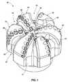
- FIG. 1is a perspective view of an earth-boring drill bit including cutting elements, according to an embodiment of the present invention.
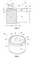
- FIG. 2is a partially cut-away side view of a cutting element having an indentation in a cutting face according to an embodiment of the present invention.
- FIG. 3is a perspective view of the cutting element of FIG. 2 .
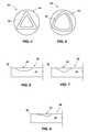
- FIG. 4is a top view of a cutting element showing a cutting face having an indentation extending along a path configured as a polygon, according to an embodiment of the present invention.
- FIG. 5is a top view of a cutting element showing a cutting face having an indentation extending along a path configured as a Reuleaux polygon, according to an embodiment of the present invention.
- FIG. 6is a cross-sectional view of a portion of a diamond table of a cutting element having an indentation with a cross-sectional shape generally defined as an elliptical arc, according to an embodiment of the present invention.
- FIG. 7is a cross-sectional view of a portion of a diamond table of a cutting element having an indentation with a cross-sectional shape generally defined as a symmetric V-shape, according to an embodiment of the present invention.
- FIG. 8is a cross-sectional view of a portion of a diamond table of a cutting element having an indentation with a cross-sectional shape generally defined as an asymmetric V-shape, according to an embodiment of the present invention.
- FIG. 9is a cross-sectional view of a portion of a diamond table of a cutting element having an indentation substantially filled with a sacrificial structure, according to an embodiment of the present invention.
- FIG. 10is a cross-sectional view of a portion of a diamond table of a cutting element with a relatively thin sacrificial structure positioned over a surface of an indentation, according to an embodiment of the present invention.
- FIG. 11is a cross-sectional view of a portion of a cutting element with a shaped region at an interface between a diamond table and a substrate corresponding to a shape of an indentation in a cutting face of the diamond table, according to an embodiment of the present invention.
- FIG. 12is a cross-sectional view of a portion of a cutting element with a shaped region at an interface between a diamond table and a substrate corresponding to a shape of an indentation in a cutting face of the diamond table positioned radially outward of the indentation, according to an embodiment of the present invention.
- FIG. 13is a schematic view of a cutting element having an indentation in a cutting face of a diamond table interacting with a formation during drilling operations, according to an embodiment of the present invention.
- earth-boring toolmeans and includes any tool used to remove formation material and form a bore (e.g., a wellbore) through the formation by way of the removal of the formation material.
- Earth-boring toolsinclude, for example, rotary drill bits (e.g., fixed-cutter or “drag” bits and roller cone or “rock” bits), hybrid bits including both fixed cutters and roller elements, coring bits, percussion bits, bi-center bits, reamers (including expandable reamers and fixed-wing reamers), and other so-called “hole-opening” tools.
- cutting elementmeans and includes any element of an earth-boring tool that is used to cut or otherwise disintegrate formation material when the earth-boring tool is used to form or enlarge a bore in the formation.
- FIG. 1illustrates an embodiment of an earth-boring tool of the present invention.
- the earth-boring tool of FIG. 1is a fixed-cutter rotary drill bit 10 having a bit body 11 that includes a plurality of blades 12 that project outwardly from the bit body 11 and are separated from one another by fluid courses 13 .
- the portions of the fluid courses 13 that extend along the radial sides (the “gage” areas of the drill bit 10 )are often referred to in the art as “junk slots.”
- the bit body 11further includes a generally cylindrical internal fluid plenum, and fluid passageways that extend through the bit body 11 to the exterior surface of the bit body 11 .
- Nozzles 18may be secured within the fluid passageways proximate the exterior surface of the bit body 11 for controlling the hydraulics of the drill bit 10 during drilling.
- a plurality of cutting elements 20is mounted to each of the blades 12 .
- the drill bit 10may be coupled to a drill string (not shown). As the drill bit 10 is rotated within the wellbore, drilling fluid may be pumped down the drill string, through the internal fluid plenum and fluid passageways within the bit body 11 of the drill bit 10 , and out from the drill bit 10 through the nozzles 18 . Formation cuttings generated by the cutting elements 20 of the drill bit 10 may be carried with the drilling fluid through the fluid courses 13 , around the drill bit 10 , and back up the wellbore through the annular space within the wellbore outside the drill string.
- FIG. 2is a side view of a partially cut-away cutting element 20 of the drill bit 10 of FIG. 1 .
- the cutting element 20includes a cutting element substrate 22 having a diamond table 24 thereon.
- the diamond table 24may comprise a polycrystalline diamond (PCD) material, having a cutting face 26 defined thereon. Additionally, an interface 28 may be defined between the cutting element substrate 22 and diamond table 24 .
- the diamond table 24may have a chamfered edge 30 . The chamfered edge 30 of the diamond table 24 shown in FIG.
- the cutting element substrate 22may have a generally cylindrical shape, as shown in FIG. 2 .
- One or more arcuate, or “radiused” edges or edge portionsmay be employed in lieu of, or in addition to, one or more chamfered surfaces at a peripheral edge of the diamond table, as known to those of ordinary skill in the art.
- the diamond table 24may be formed on the cutting element substrate 22 , or the diamond table 24 and the cutting element substrate 22 may be separately formed and subsequently attached together.
- the cutting element substrate 22may be formed from a material that is relatively hard and resistant to wear.
- the cutting element substrate 22may be formed from and include a ceramic-metal composite material (which is often referred to as a “cermet” material).
- the cutting element substrate 22may include a cemented carbide material, such as a cemented tungsten carbide material, in which tungsten carbide particles are cemented together in a metallic binder material.
- the metallic binder materialmay include, for example, cobalt, nickel, iron, or alloys and mixtures thereof.
- cutting element substrate 22may comprise two pieces, the piece immediately supporting diamond table 24 and on which may be formed and bonded to another, longer piece of like diameter.
- the cutting elements 20may be secured in pockets on blades 12 as depicted in FIG. 1 , such as by brazing.
- a circumferentially extending indentation 34may be defined in the cutting face 26 of the cutting element 20 .
- a generally annular, arcuate indentation 34may be defined in the cutting face 26 of the cutting element 20 , as shown in FIGS. 2 and 3 .
- the indentation 34may be positioned proximate to an edge of the cutting element 20 , such as proximate to the chamfer surface 32 .
- the indentation 34may be defined by an arcuate cross-section having a primary surface with a cross-sectional dimension defined by a radius R 1 .
- the indentationmay be an arcuate groove defined by a radius R 1 of about 0.25 inch (about 6.35 mm) and having a depth D of about 0.012 inch (about 0.30 mm) relative to substantially planar surfaces 36 of the cutting face 26 .
- the radially outer edge of the indentation 34may be positioned a distance X of about 0.031 inch (about 0.79 mm) from the chamfer surface 32 , and the chamfer edge 30 may have a width of about a about 0.010 inch (about 0.30 mm).
- the overall dimension of the cutting element 20may be defined by a radius R 2 of about 0.315 inch (about 8 mm).
- a radially inward edge 38 and radially outward edge 40 of the indentation 34may be radiused, or otherwise smoothed, to provide a relatively smooth transition between the indentation 34 and substantially planar surfaces 36 of the cutting face 26 of the cutting element 20 .
- the path that the indentation 34 extends alongmay be defined by other shapes, rather than a path configured as an annulus or a circle.
- the indentation 34may extend along a path shaped generally as a polygon, such as a generally triangular path, as shown in FIG. 4 .
- the indentation 34may extend along a path generally shaped as a regular n-sided polygon, where n may have any value from 3 to infinity, whereby n equal to infinity is equivalent to the aforementioned circular embodiment.
- the path that the indentation 34 extends alongmay be generally shaped as a Reuleaux polygon (i.e., a curvilinear polygon built up of circular arcs), such as a path shaped generally as a Reuleaux triangle, as shown in FIG. 5 .
- the indentation 34may be segmented, comprising a plurality of separate indentations that do not follow a single continuous path.
- a transverse cross-sectional shape of the indentation 34 taken across a segment thereofmay be defined by other shapes, in addition to a circular arc.
- a cross-section of the indentation 34may be generally defined as one or more of an elliptical arc ( FIG. 6 ), a symmetric curved shape, an asymmetric curved shape, a symmetric V-shape ( FIG. 7 ), and an asymmetric V-shape ( FIG. 8 ).
- the indentation 34may be formed in the diamond table 24 after the diamond table 24 has been formed, such as by using electrical discharge machining (EDM), whereby a desired shape is achieved by using electrical discharges from an electrode (not shown).
- EDMelectrical discharge machining
- the diamond table 24may be moved relative an electrode having a shape of a desired cross-section of the indentation 34 (and/or the electrode may be moved along a desired path relative to the diamond table 24 ) to form the indentation 34 .
- an electrode having an arcuate shapemay be lowered into the cutting face 26 of the diamond table 24 , and then the diamond table 24 may be rotated to form an indentation 34 comprising an arcuate groove following an annular path.
- an electrode die having a negative shape of the desired indentation 34i.e., a protrusion
- the indentation 34 in the diamond table 24may include a sacrificial structure 42 positioned therein.
- the sacrificial structure 42may substantially fill the indentation 34 in the diamond table 24 , such that a surface 44 of the sacrificial structure 42 may be substantially aligned and coplanar with the adjacent, substantially planar surfaces 36 of the cutting face 26 of the diamond table 24 , as shown in FIG. 9 .
- the sacrificial structure 42may be a relatively thin material layer positioned over a surface 46 of the indentation 34 , as shown in FIG. 10 .
- the sacrificial structure 42may be comprised of a material that is softer than the diamond table 24 , or that is otherwise more susceptible to wear than the diamond table 24 , such as one or more of a ceramic, a cermet and a refractory metal.
- the material of the sacrificial structure 42may be one or more of tungsten carbide, aluminum oxide, tungsten, niobium, tantalum, hafnium, molybdenum, and carbides formed therefrom.
- the indentation 34may be formed into the diamond table 24 during the formation of the diamond table 24 .
- the sacrificial structure 42may be positioned within a mold (not shown) and powdered precursor material comprising diamond particles may be positioned over (e.g., around) the sacrificial structure 42 . Then the powdered precursor material may be compacted and sintered in the presence of a catalyst mixed with the diamond particles or swept from an adjacent substrate as known in the art to form the diamond table 24 , with the sacrificial structure 42 forming the indentation 34 in the diamond table 24 .
- the entire sacrificial structure 42 , or a portion thereof,may then be removed, such as by sandblasting, machining, acid leaching or another process, or the entire sacrificial structure 31 structure 42 , or a portion thereof, may remain positioned in the indentation 34 to be removed by the formation during drilling operations. Additionally, for embodiments wherein the entire sacrificial structure 42 , or a portion thereof, may then be removed, such as by sandblasting, machining, acid leaching or another process, the diamond table 24 may be machined, such as by an EDM process, to a final geometry.
- the sacrificial structure 42may be positioned within the indentation 34 in the diamond table after the indentation 34 is formed therein, such as after a high-pressure/high-temperature (HPHT) process.
- a sacrificial structure 42may comprise one or more of a polymer, a glass, a ceramic, a cermet, a refractory metal, and a combination thereof that may be positioned within the indentation 34 of the diamond table 24 .
- the cutting face 26 of the cutting element 20may appear substantially planar in an unused state, with the sacrificial structure 42 positioned therein.
- the sacrificial structure 42may wear away and the indentation 34 may become exposed for engagement with a formation during drilling operations.
- a powder performsuch as a diamond comprising powder contained in a cylindrical niobium cup
- a shaped moldsuch as a mold having a shaped protrusion
- the powder performmay be positioned adjacent the shaped mold (not shown) during a high-pressure/high-temperature (HPHT) process and a shape imparted by the shaped mold may be retained throughout a sintering cycle to form the indentation 34 in the diamond table 24 .
- the shape imparted by the moldmay be near a desired net shape of the indentation 34 , and the final shape of the indentation 34 may be machined, such as by an EDM process, to a final geometry.
- the catalyst materialmay be removed from the hard polycrystalline material of the diamond table 24 after the HPHT process, as known in the art.
- a leaching processmay be used to remove catalyst material from interstitial spaces between the inter-bonded grains of the hard polycrystalline material of the diamond table 24 .
- the hard polycrystalline materialmay be leached using a leaching agent and process such as those described more fully in, for example, U.S. Pat. No. 5,127,923 to Bunting et al., (issued Jul. 7, 1992), and U.S. Pat. No. 4,224,380 to Bovenkerk et al. (issued Sep. 23, 1980), the disclosure of each of which patent is incorporated herein in its entirety by this reference.
- aqua regiaa mixture of concentrated nitric acid (HNO 3 ) and concentrated hydrochloric acid (HCl)
- HNO 3concentrated nitric acid
- HClconcentrated hydrochloric acid
- HFboiling hydrofluoric acid
- One particularly suitable leaching agentis hydrochloric acid (HCl) at a temperature of above 110° C., which may be provided in contact with the hard polycrystalline material of the diamond table 24 for a period of about two hours to about 60 hours, depending upon the size of the body comprising the hard polycrystalline material.
- the interstitial spaces between the inter-bonded grains within the hard polycrystalline materialmay be at least substantially free of catalyst material used to catalyze formation of inter-granular bonds between the grains in the hard polycrystalline material.
- leachingmay be selectively applied to specific regions of the diamond table table 24 , and not to other regions.
- a maskmay be applied to a region of the diamond table 24 , such as the indentation 34 or a region of the indentation 34 in the diamond table 24 , and only the unmasked regions may be leached.
- an outer surface of the diamond table 24may be physically modified, such as by polishing to a smooth or mirrored finish.
- an outer surface of the diamond table 24may have a reduced surface roughness, such as described in U.S. Pat. No. 6,145,608, which issued on Nov. 14, 2000 to Lund et al., and is assigned to the assignee of the present application; U.S. Pat. No. 5,653,300, which issued Aug. 5, 1997 to Lund et al., and is assigned to the assignee of the present application; and U.S. Pat. No. 5,447,208, which issued Sep. 5, 1995 to Lund et al., and is assigned to the assignee of the present application, the disclosure of each of which is incorporated herein in its entirety by this reference.
- a cutting face or leading face of PDCmight be lapped to a surface finish of 20 ⁇ in. (about 0.508 ⁇ m) to 40 ⁇ in. (about 1.02 ⁇ m) root mean square RMS (all surface finishes referenced herein being RMS), which is relatively smooth to the touch and visually planar (if the cutting face is itself flat), but which includes a number of surface anomalies and exhibits a degree of roughness which is readily visible to one even under very low power magnification, such as a 10 ⁇ jeweler's loupe.
- an exterior surface of the diamond table 24may be treated to have a greatly reduced surface roughness.
- an exterior surface of the diamond table 24may be polished a surface roughness of about 0.5 ⁇ in. (about 0.0127 ⁇ m) RMS.
- the surface roughness of a surface of the diamond table 24may be reduced by lapping of the cutting face 26 on conventional cast iron laps known in the art by using progressively smaller diamond grit suspended in a glycol, glycerine or other suitable carrier liquid.
- the lappingmay be conducted as a three-step process commencing with a 70 micron grit, progressing to a 40 micron grit and then to a grit of about 1 to 3 microns in size.
- standard lapping techniques for a PDC cutting elementwhich may follow an initial electrodischarge grinding of the cutting face, finish lapping in one step with 70 micron grit.
- 70 micron gritis of the consistency of fine sand or crystalline material, while 1 to 3 micron grit is similar in consistency to powdered sugar.
- the surface roughness of a surface of the diamond table 24may be reduced by placing the surface in contact with a dry, rotating diamond wheel.
- a dry, rotating diamond wheelFor example, the Winter RB778 resin bonded diamond wheel, offered by Ernst Winter & Sons, Inc. of Travelers Rest, S.C., may be utilized. It may be important that the wheel be cooled as the diamond wheel is of resin bonded construction. Elevated temperatures may result in the destruction of the wheel. The nature of the polishing process may require that the abrasive surface be kept dry. However, the wheel may be moistened with water at the start of the polishing process to reduce drag and facilitate proper orientation of the diamond table 24 against the wheel. In addition, a temperature range wherein polishing may be effected may be between about 140° F.
- polishers employedmay rotate at about 3500 RPM, it is believed that a range between about 3000 RPM and about 5000 RPM would likely be adequate.
- About 2 lb. force (about 0.9 Kg) to about 8 lb. force (about 3.6 Kg)may be applied to the diamond table 24 against the wheel.
- the finish of an exterior surface of the diamond table 24may be smoothed to about 0.5 ⁇ in. (about 0.0127 ⁇ m) RMS or less surface finish roughness approaching a true “mirror” finish.
- the cutting element cutting surfacesmay be polished by other methods, such as ion beams or chemicals, although the inherently inert chemical nature of diamond may make the latter approach somewhat difficult for diamond.
- an industry-standard PDC or other superhard cutting elementmay have a lapped surface finish on the cutting face with irregularities or roughness (measured vertically from the surface) on the order of 20 ⁇ in. (about 0.508 ⁇ m) to 40 ⁇ in. (about 1.02 ⁇ m) RMS, as a result of the above-described polishing, some embodiments may have a diamond table 24 surface roughness between about 0.3 ⁇ in. RMS and about 0.5 ⁇ in. (about 0.0127 ⁇ m) RMS. Additional embodiments may have a diamond table 24 surface roughness between about 0.4 ⁇ in. (about 0.0102 ⁇ m) RMS and about 0.6 ⁇ in. (about 0.0152 ⁇ m) RMS.
- the diamond table 24may have a surface roughness less than about 10 ⁇ in. (about 0.254 ⁇ m) RMS. In further embodiments, the diamond table 24 may have a surface roughness less than about 2 ⁇ in. (about 0.0508 ⁇ m) RMS. In yet further embodiments, the diamond table 24 may have a surface roughness less than about 0.5 ⁇ in. (about 0.0127 ⁇ m) RMS, approaching a true “mirror” finish. The foregoing surface roughness measurements of the diamond table 24 may be measured using a calibrated HOMMEL® America Model T-4000 diamond stylus profilometer contacting the surface of the diamond table 24 .
- selected surfaces of the diamond table 24may be polished or otherwise smoothed to have a reduced surface roughness.
- the substantially planar surfaces 36 of the cutting face 26may have a reduced surface roughness.
- the surface of the indentation 34may have a reduced surface roughness.
- the entire cutting face 26 of the diamond table 24may have a reduced surface roughness.
- the chamfer 32 and/or other side surfaces of the diamond table 24may have a reduced surface roughness.
- all of the exposed surfaces of the diamond table 24may have a reduced surface roughness.
- a shape of the interface 28 between the diamond table 24 and the substrate 22 of the cutting element 20may be configured to effectively distribute stresses caused by cutting forces in and around the indentation 34 in the diamond table 24 , to improve the structural integrity of the cutting element 20 .
- a shaped region 48 corresponding to a shape of the indentation 34 in the cutting face 26 of diamond table 24may define a region of the interface 28 , such as shown in FIG. 11 .
- the shaped region 48 of the interface 28may be defined by an indentation 50 in the substrate 22 and a protrusion 52 ( FIGS. 11 and 12 ) of the diamond table 24 at the interface 28 .
- the shaped region 48 of the interface 28may provide a generally uniform thickness of the diamond table 24 .
- the shaped region 48 of the interface 28 corresponding to the indentation 34 in the diamond table 24may be positioned directly, longitudinally, below the indentation 34 in the diamond table 24 .
- At least a portion of the shaped region 48 of the interface 28 corresponding to the indentation 34 in the diamond table 24may underlie the indentation 34 at a position radially inward of the indentation 34 relative to a longitudinal axis 54 ( FIG. 2 ) of the cutting element 20 .
- at least a portion of the shaped region 48 of the interface 28 corresponding to the indentation 34 in the diamond table 24may underlie the indentation 34 at a position radially outward of the indentation 34 relative to a longitudinal axis 54 ( FIG. 2 ) of the cutting element 20 , as shown in FIG. 12 .
- Such a configurationmay account for a projected direction of travel of the cutting element 20 relative to a formation (as indicated by the dashed lines in FIG. 12 ), as this may correspond to a primary general direction of cutting forces applied to the cutting element 20 during drilling operations.
- the shaped region of the interface 28may be sized, shaped and positioned to reduce stress concentrations, and/or to provide sufficient structural strength to withstand anticipated stress concentrations, that may result from drilling operations.
- the diamond layering composition of the diamond table 24may be tailored in the shaped region to compensate for residual stresses and provide a tailored material property of the diamond table 24 , such as a tailored strength and toughness, in the shaped region.
- the geometry of the cutting element 20may provide improved aggressiveness for a given depth-of-cut (DOC).
- DOCdepth-of-cut
- a DOC up to about 0.15 inch (about 3.8 mm)may be targeted in a drilling operation such as shown in FIG. 13 .
- the region of the formation 56 that contacts the indentation 34 in the cutting face 26 of the diamond table 24 of the cutting element 20may contact the cutting element 20 at an angle ⁇ different than an angle ⁇ of the substantially planar surfaces 36 of the cutting face 26 .
- the effective rake angle ⁇ of the cutting element 20may be less than the backrake angle ⁇ of the cutting element 20 , thus resulting in increased aggressivity.
- a single bit body 11 designmay be combined with different cutting element 20 designs to provide fixed-cutter rotary drill bits 10 having the same bit body 11 design, yet having various effective rake angles ⁇ .
- a first earth-boring drill bit having a first bit bodymay include cutting elements having a substantially planar cutting element face with no indentation formed therein and have a first effective rake angle ⁇ .
- a second earth-boring drill bit having a second bit body, having the same design as the first bit body,may include cutting elements having indentations in the face of the cutting element, as described herein, and may have a second effective rake angle ⁇ , different than the first effective rake angle of the first bit.
- the effective rake angle ⁇ and aggressiveness of a cutting element 20may be varied, without a change in bit body 11 design.
- a depth-of-cut limiting feature on an earth-boring toolmay be positioned to facilitate interaction between an uncut earth formation and an indentation 34 in the cutting face 26 of the diamond table 24 during earth-boring operations.
- the depth-of-cut limiting feature on an earth-boring toolmay be one or more of an outer surface of a blade 12 of the drill bit 10 shown in FIG. 1 and a bearing block feature as described in U.S. patent application Ser. No. 12/766,988, filed Apr. 26, 2010, for “BEARING BLOCKS FOR DRILL BITS, DRILL BIT ASSEMBLIES INCLUDING BEARING BLOCKS AND RELATED METHODS,” the disclosure of which is incorporated herein in its entirety by this reference.
- the depth-of-cut limiting featuremay be positioned to be aligned with the deepest portion of the indentation 34 in the cutting face 26 of the diamond table 24 .
- the cutting element 20may have a generally cylindrical shape and the indentation 34 may have a generally annular shape, it may be the deepest portion of the indentation 34 that extends the furthest from the body of the earth-boring tool (i.e., the portion that extends furthest from the blade 12 of the drill bit 10 ) that is aligned with the depth-of-cut limiting feature.
- the uncut formationmay contact the cutting face 26 of the diamond table 24 well into the indentation 34 during drilling operations, such that the curved or angled surface of the indentation 34 positioned radially outward (relative to a primary axis of the cutting element 20 ) of the deepest portion of the indentation 34 may interact with the uncut formation 56 and provide a desired effective rake angle ⁇ .
Landscapes
- Engineering & Computer Science (AREA)
- Life Sciences & Earth Sciences (AREA)
- Mining & Mineral Resources (AREA)
- Geology (AREA)
- Mechanical Engineering (AREA)
- Geochemistry & Mineralogy (AREA)
- Physics & Mathematics (AREA)
- Environmental & Geological Engineering (AREA)
- Fluid Mechanics (AREA)
- General Life Sciences & Earth Sciences (AREA)
- Crystallography & Structural Chemistry (AREA)
- Chemical & Material Sciences (AREA)
- Manufacturing & Machinery (AREA)
- Earth Drilling (AREA)
- Cutting Tools, Boring Holders, And Turrets (AREA)
- Polishing Bodies And Polishing Tools (AREA)
Abstract
Description
Claims (23)
Priority Applications (8)
| Application Number | Priority Date | Filing Date | Title |
|---|---|---|---|
| US13/092,396US8684112B2 (en) | 2010-04-23 | 2011-04-22 | Cutting elements for earth-boring tools, earth-boring tools including such cutting elements and related methods |
| US13/477,905US9243452B2 (en) | 2011-04-22 | 2012-05-22 | Cutting elements for earth-boring tools, earth-boring tools including such cutting elements, and related methods |
| US13/609,575US9103174B2 (en) | 2011-04-22 | 2012-09-11 | Cutting elements for earth-boring tools, earth-boring tools including such cutting elements and related methods |
| US14/063,909US8919462B2 (en) | 2010-04-23 | 2013-10-25 | Cutting elements for earth-boring tools, earth-boring tools including such cutting elements and related methods |
| US14/480,293US9650837B2 (en) | 2011-04-22 | 2014-09-08 | Multi-chamfer cutting elements having a shaped cutting face and earth-boring tools including such cutting elements |
| US14/534,365US10006253B2 (en) | 2010-04-23 | 2014-11-06 | Cutting elements for earth-boring tools and earth-boring tools including such cutting elements |
| US14/980,653US10337255B2 (en) | 2011-04-22 | 2015-12-28 | Cutting elements for earth-boring tools, earth-boring tools including such cutting elements, and related methods |
| US15/585,373US10428591B2 (en) | 2011-04-22 | 2017-05-03 | Structures for drilling a subterranean formation |
Applications Claiming Priority (2)
| Application Number | Priority Date | Filing Date | Title |
|---|---|---|---|
| US32748410P | 2010-04-23 | 2010-04-23 | |
| US13/092,396US8684112B2 (en) | 2010-04-23 | 2011-04-22 | Cutting elements for earth-boring tools, earth-boring tools including such cutting elements and related methods |
Related Child Applications (1)
| Application Number | Title | Priority Date | Filing Date |
|---|---|---|---|
| US14/063,909ContinuationUS8919462B2 (en) | 2010-04-23 | 2013-10-25 | Cutting elements for earth-boring tools, earth-boring tools including such cutting elements and related methods |
Publications (2)
| Publication Number | Publication Date |
|---|---|
| US20110259642A1 US20110259642A1 (en) | 2011-10-27 |
| US8684112B2true US8684112B2 (en) | 2014-04-01 |
Family
ID=44814827
Family Applications (3)
| Application Number | Title | Priority Date | Filing Date |
|---|---|---|---|
| US13/092,396Active2032-04-16US8684112B2 (en) | 2010-04-23 | 2011-04-22 | Cutting elements for earth-boring tools, earth-boring tools including such cutting elements and related methods |
| US14/063,909ActiveUS8919462B2 (en) | 2010-04-23 | 2013-10-25 | Cutting elements for earth-boring tools, earth-boring tools including such cutting elements and related methods |
| US14/534,365Active2032-02-16US10006253B2 (en) | 2010-04-23 | 2014-11-06 | Cutting elements for earth-boring tools and earth-boring tools including such cutting elements |
Family Applications After (2)
| Application Number | Title | Priority Date | Filing Date |
|---|---|---|---|
| US14/063,909ActiveUS8919462B2 (en) | 2010-04-23 | 2013-10-25 | Cutting elements for earth-boring tools, earth-boring tools including such cutting elements and related methods |
| US14/534,365Active2032-02-16US10006253B2 (en) | 2010-04-23 | 2014-11-06 | Cutting elements for earth-boring tools and earth-boring tools including such cutting elements |
Country Status (9)
| Country | Link |
|---|---|
| US (3) | US8684112B2 (en) |
| EP (1) | EP2561171B1 (en) |
| CN (1) | CN102933785B (en) |
| BR (1) | BR112012027211A2 (en) |
| CA (1) | CA2797137C (en) |
| MX (1) | MX2012012226A (en) |
| NO (1) | NO2561171T3 (en) |
| RU (1) | RU2577342C2 (en) |
| WO (1) | WO2011133850A2 (en) |
Cited By (21)
| Publication number | Priority date | Publication date | Assignee | Title |
|---|---|---|---|---|
| US9103174B2 (en) | 2011-04-22 | 2015-08-11 | Baker Hughes Incorporated | Cutting elements for earth-boring tools, earth-boring tools including such cutting elements and related methods |
| US9243452B2 (en) | 2011-04-22 | 2016-01-26 | Baker Hughes Incorporated | Cutting elements for earth-boring tools, earth-boring tools including such cutting elements, and related methods |
| US9376867B2 (en) | 2011-09-16 | 2016-06-28 | Baker Hughes Incorporated | Methods of drilling a subterranean bore hole |
| US9428966B2 (en) | 2012-05-01 | 2016-08-30 | Baker Hughes Incorporated | Cutting elements for earth-boring tools, earth-boring tools including such cutting elements, and related methods |
| US9650837B2 (en) | 2011-04-22 | 2017-05-16 | Baker Hughes Incorporated | Multi-chamfer cutting elements having a shaped cutting face and earth-boring tools including such cutting elements |
| US9821437B2 (en) | 2012-05-01 | 2017-11-21 | Baker Hughes Incorporated | Earth-boring tools having cutting elements with cutting faces exhibiting multiple coefficients of friction, and related methods |
| US9920576B2 (en) | 2015-10-02 | 2018-03-20 | Baker Hughes, A Ge Company, Llc | Cutting elements for earth-boring tools, earth-boring tools including such cutting elements, and related methods |
| US9931714B2 (en) | 2015-09-11 | 2018-04-03 | Baker Hughes, A Ge Company, Llc | Methods and systems for removing interstitial material from superabrasive materials of cutting elements using energy beams |
| US10006253B2 (en) | 2010-04-23 | 2018-06-26 | Baker Hughes Incorporated | Cutting elements for earth-boring tools and earth-boring tools including such cutting elements |
| US10016876B2 (en) | 2007-11-05 | 2018-07-10 | Baker Hughes, A Ge Company, Llc | Methods of forming polycrystalline compacts and earth-boring tools including polycrystalline compacts |
| US10329843B2 (en) | 2016-05-23 | 2019-06-25 | Varel Europe S.A.S. | Fixed cutter drill bit having core receptacle with concave core cutter |
| US10400517B2 (en) | 2017-05-02 | 2019-09-03 | Baker Hughes, A Ge Company, Llc | Cutting elements configured to reduce impact damage and related tools and methods |
| US10465447B2 (en) | 2015-03-12 | 2019-11-05 | Baker Hughes, A Ge Company, Llc | Cutting elements configured to mitigate diamond table failure, earth-boring tools including such cutting elements, and related methods |
| US10570668B2 (en) | 2018-07-27 | 2020-02-25 | Baker Hughes, A Ge Company, Llc | Cutting elements configured to reduce impact damage and mitigate polycrystalline, superabrasive material failure earth-boring tools including such cutting elements, and related methods |
| US10577870B2 (en) | 2018-07-27 | 2020-03-03 | Baker Hughes, A Ge Company, Llc | Cutting elements configured to reduce impact damage related tools and methods—alternate configurations |
| US10697248B2 (en) | 2017-10-04 | 2020-06-30 | Baker Hughes, A Ge Company, Llc | Earth-boring tools and related methods |
| US10954721B2 (en) | 2018-06-11 | 2021-03-23 | Baker Hughes Holdings Llc | Earth-boring tools and related methods |
| US11578538B2 (en) | 2020-01-09 | 2023-02-14 | Schlumberger Technology Corporation | Cutting element with nonplanar face to improve cutting efficiency and durability |
| US20230219185A1 (en)* | 2022-01-11 | 2023-07-13 | Baker Hughes Oilfield Operations Llc | Polycrystalline diamond compact cutting elements, methods of forming same and earth-boring tools |
| US11920409B2 (en) | 2022-07-05 | 2024-03-05 | Baker Hughes Oilfield Operations Llc | Cutting elements, earth-boring tools including the cutting elements, and methods of forming the earth-boring tools |
| US12134938B2 (en) | 2021-02-05 | 2024-11-05 | Baker Hughes Oilfield Operations Llc | Cutting elements for earth-boring tools, methods of manufacturing earth-boring tools, and related earth-boring tools |
Families Citing this family (38)
| Publication number | Priority date | Publication date | Assignee | Title |
|---|---|---|---|---|
| SA111320374B1 (en) | 2010-04-14 | 2015-08-10 | بيكر هوغيس انكوبوريتد | Method Of Forming Polycrystalline Diamond From Derivatized Nanodiamond |
| US9062505B2 (en) | 2011-06-22 | 2015-06-23 | Us Synthetic Corporation | Method for laser cutting polycrystalline diamond structures |
| US9212546B2 (en) | 2012-04-11 | 2015-12-15 | Baker Hughes Incorporated | Apparatuses and methods for obtaining at-bit measurements for an earth-boring drilling tool |
| US9605487B2 (en) | 2012-04-11 | 2017-03-28 | Baker Hughes Incorporated | Methods for forming instrumented cutting elements of an earth-boring drilling tool |
| US9394782B2 (en) | 2012-04-11 | 2016-07-19 | Baker Hughes Incorporated | Apparatuses and methods for at-bit resistivity measurements for an earth-boring drilling tool |
| GB201210876D0 (en)* | 2012-06-20 | 2012-08-01 | Element Six Abrasives Sa | Inserts and method for making same |
| US9388639B2 (en) | 2012-10-26 | 2016-07-12 | Baker Hughes Incorporated | Rotatable cutting elements and related earth-boring tools and methods |
| US9303461B2 (en) | 2012-10-26 | 2016-04-05 | Baker Hughes Incorporated | Cutting elements having curved or annular configurations for earth-boring tools, earth-boring tools including such cutting elements, and related methods |
| US20140183798A1 (en)* | 2012-12-28 | 2014-07-03 | Smith International, Inc. | Manufacture of cutting elements having lobes |
| US9140072B2 (en) | 2013-02-28 | 2015-09-22 | Baker Hughes Incorporated | Cutting elements including non-planar interfaces, earth-boring tools including such cutting elements, and methods of forming cutting elements |
| CN103089154B (en)* | 2013-02-28 | 2015-07-08 | 西南石油大学 | a hybrid drill |
| US9644430B2 (en)* | 2013-03-15 | 2017-05-09 | Baker Hughes Incorporated | Cutting elements for earth-boring tools, earth-boring tools including such cutting elements, and related methods |
| US9534450B2 (en) | 2013-07-22 | 2017-01-03 | Baker Hughes Incorporated | Thermally stable polycrystalline compacts for reduced spalling, earth-boring tools including such compacts, and related methods |
| US9845642B2 (en) | 2014-03-17 | 2017-12-19 | Baker Hughes Incorporated | Cutting elements having non-planar cutting faces with selectively leached regions, earth-boring tools including such cutting elements, and related methods |
| US9714545B2 (en) | 2014-04-08 | 2017-07-25 | Baker Hughes Incorporated | Cutting elements having a non-uniform annulus leach depth, earth-boring tools including such cutting elements, and related methods |
| US9605488B2 (en) | 2014-04-08 | 2017-03-28 | Baker Hughes Incorporated | Cutting elements including undulating boundaries between catalyst-containing and catalyst-free regions of polycrystalline superabrasive materials and related earth-boring tools and methods |
| CN110130833A (en)* | 2014-06-18 | 2019-08-16 | 哈利伯顿能源服务公司 | Boring method |
| US9863189B2 (en) | 2014-07-11 | 2018-01-09 | Baker Hughes Incorporated | Cutting elements comprising partially leached polycrystalline material, tools comprising such cutting elements, and methods of forming wellbores using such cutting elements |
| US10502000B2 (en)* | 2014-11-05 | 2019-12-10 | Duane Shotwell | Reamer cutting insert for use in drilling operations |
| US10036209B2 (en)* | 2014-11-11 | 2018-07-31 | Schlumberger Technology Corporation | Cutting elements and bits for sidetracking |
| GB2549051A (en)* | 2015-01-29 | 2017-10-04 | Nat Oilwell Dht Lp | Anti-balling drill bit and method of making same |
| CN104832101B (en)* | 2015-05-15 | 2018-07-03 | 中国水利水电第十工程局有限公司 | Bi base material type cutting element and the down-hole hammer drilling with the cutting element |
| US10392868B2 (en)* | 2015-09-30 | 2019-08-27 | Schlumberger Technology Corporation | Milling wellbore casing |
| AU2017207510B9 (en)* | 2016-01-14 | 2021-03-25 | Huwais IP Holding LLC | Autografting tool with enhanced flute profile and methods of use |
| US10458189B2 (en) | 2017-01-27 | 2019-10-29 | Baker Hughes, A Ge Company, Llc | Earth-boring tools utilizing selective placement of polished and non-polished cutting elements, and related methods |
| US10619422B2 (en)* | 2017-02-16 | 2020-04-14 | Baker Hughes, A Ge Company, Llc | Cutting tables including rhenium-containing structures, and related cutting elements, earth-boring tools, and methods |
| CN107288551B (en)* | 2017-08-15 | 2018-04-10 | 吉林大学 | A kind of polar region deep ice layer drilling uses ice auger drill bit |
| US11098532B2 (en) | 2017-09-05 | 2021-08-24 | Schlumberger Technology Corporation | Cutting elements having non-planar surfaces and tools incorporating the same |
| US10584581B2 (en) | 2018-07-03 | 2020-03-10 | Baker Hughes, A Ge Company, Llc | Apparatuses and method for attaching an instrumented cutting element to an earth-boring drilling tool |
| US11180989B2 (en) | 2018-07-03 | 2021-11-23 | Baker Hughes Holdings Llc | Apparatuses and methods for forming an instrumented cutting for an earth-boring drilling tool |
| CA3115839A1 (en) | 2018-11-06 | 2020-05-14 | Huwais IP Holding LLC | Autografting tool for deep reach applications |
| US11920408B2 (en) | 2019-10-21 | 2024-03-05 | Schlumberger Technology Corporation | Cutter with geometric cutting edges |
| WO2021158215A1 (en)* | 2020-02-05 | 2021-08-12 | Baker Hughes Oilfield Operations Llc | Cutter geometry utilizing spherical cutouts |
| EP4508299A1 (en)* | 2022-04-13 | 2025-02-19 | National Oilwell Varco, L.P. | Drill bit cutter elements with multiple surface finishes |
| JP1749454S (en)* | 2022-09-28 | 2023-07-27 | cutting insert | |
| US12320199B1 (en) | 2022-11-22 | 2025-06-03 | Baker Hughes Oilfield Operations Llc | Cutting elements and geometries for reduced vibrations, earth-boring tools, and related methods |
| GB2638116A (en)* | 2023-11-01 | 2025-08-20 | Element Six Tech Ltd | CVD single crystal diamond material |
| US20250179877A1 (en)* | 2023-12-01 | 2025-06-05 | Halliburton Energy Services, Inc. | Cutting element including one or more asymmetric relief surfaces |
Citations (58)
| Publication number | Priority date | Publication date | Assignee | Title |
|---|---|---|---|---|
| US4224380A (en) | 1978-03-28 | 1980-09-23 | General Electric Company | Temperature resistant abrasive compact and method for making same |
| EP0079699A1 (en) | 1981-11-12 | 1983-05-25 | Minnesota Mining And Manufacturing Company | Apparatus for removing toner from and applying offset preventive liquid to a fixing roller |
| US4538690A (en) | 1983-02-22 | 1985-09-03 | Nl Industries, Inc. | PDC cutter and bit |
| US4539018A (en) | 1984-05-07 | 1985-09-03 | Hughes Tool Company--USA | Method of manufacturing cutter elements for drill bits |
| US4558753A (en) | 1983-02-22 | 1985-12-17 | Nl Industries, Inc. | Drag bit and cutters |
| US4593777A (en) | 1983-02-22 | 1986-06-10 | Nl Industries, Inc. | Drag bit and cutters |
| US4629373A (en) | 1983-06-22 | 1986-12-16 | Megadiamond Industries, Inc. | Polycrystalline diamond body with enhanced surface irregularities |
| US4858707A (en) | 1988-07-19 | 1989-08-22 | Smith International, Inc. | Convex shaped diamond cutting elements |
| US4872520A (en) | 1987-01-16 | 1989-10-10 | Triton Engineering Services Company | Flat bottom drilling bit with polycrystalline cutters |
| US4984642A (en) | 1989-05-17 | 1991-01-15 | Societe Industrielle De Combustible Nucleaire | Composite tool comprising a polycrystalline diamond active part |
| US4997049A (en) | 1988-08-15 | 1991-03-05 | Klaus Tank | Tool insert |
| US5007207A (en) | 1987-12-22 | 1991-04-16 | Cornelius Phaal | Abrasive product |
| US5054246A (en) | 1988-09-09 | 1991-10-08 | Cornelius Phaal | Abrasive compacts |
| US5078219A (en) | 1990-07-16 | 1992-01-07 | The United States Of America As Represented By The Secretary Of The Interior | Concave drag bit cutter device and method |
| US5127923A (en) | 1985-01-10 | 1992-07-07 | U.S. Synthetic Corporation | Composite abrasive compact having high thermal stability |
| EP0546725A1 (en) | 1991-11-30 | 1993-06-16 | Camco Drilling Group Limited | Improvents in or relating to cutting elements for rotary drill bits |
| WO1994015058A1 (en) | 1992-12-23 | 1994-07-07 | Baroid Technology, Inc. | Drill bit having chip breaker polycrystalline diamond compact and hard metal insert at gauge surface |
| US5333699A (en) | 1992-12-23 | 1994-08-02 | Baroid Technology, Inc. | Drill bit having polycrystalline diamond compact cutter with spherical first end opposite cutting end |
| US5355969A (en) | 1993-03-22 | 1994-10-18 | U.S. Synthetic Corporation | Composite polycrystalline cutting element with improved fracture and delamination resistance |
| WO1994027769A1 (en) | 1993-05-27 | 1994-12-08 | Sandvik Ab | Chip breaking insert provided with at least one body of diamond or cubic boron nitride, and a method of making the insert |
| US5377773A (en) | 1992-02-18 | 1995-01-03 | Baker Hughes Incorporated | Drill bit having combined positive and negative or neutral rake cutters |
| US5447208A (en) | 1993-11-22 | 1995-09-05 | Baker Hughes Incorporated | Superhard cutting element having reduced surface roughness and method of modifying |
| US5533582A (en) | 1994-12-19 | 1996-07-09 | Baker Hughes, Inc. | Drill bit cutting element |
| US5549171A (en) | 1994-08-10 | 1996-08-27 | Smith International, Inc. | Drill bit with performance-improving cutting structure |
| US5607024A (en) | 1995-03-07 | 1997-03-04 | Smith International, Inc. | Stability enhanced drill bit and cutting structure having zones of varying wear resistance |
| EP0835981A2 (en) | 1996-10-11 | 1998-04-15 | Camco Drilling Group Limited | Cutting structure for rotary drill bits |
| US5984005A (en) | 1995-09-22 | 1999-11-16 | Weatherford/Lamb, Inc. | Wellbore milling inserts and mills |
| US6045440A (en) | 1997-11-20 | 2000-04-04 | General Electric Company | Polycrystalline diamond compact PDC cutter with improved cutting capability |
| US6059054A (en) | 1996-06-21 | 2000-05-09 | Smith International, Inc. | Non-symmetrical stress-resistant rotary drill bit cutter element |
| US6065554A (en) | 1996-10-11 | 2000-05-23 | Camco Drilling Group Limited | Preform cutting elements for rotary drill bits |
| US6068071A (en) | 1996-05-23 | 2000-05-30 | U.S. Synthetic Corporation | Cutter with polycrystalline diamond layer and conic section profile |
| WO2000048789A1 (en) | 1999-02-19 | 2000-08-24 | U.S. Synthetic Corporation | Method for forming a superabrasive polycrystalline cutting tool with an integral chipbreaker feature |
| US6164394A (en) | 1996-09-25 | 2000-12-26 | Smith International, Inc. | Drill bit with rows of cutters mounted to present a serrated cutting edge |
| US6196910B1 (en) | 1998-08-10 | 2001-03-06 | General Electric Company | Polycrystalline diamond compact cutter with improved cutting by preventing chip build up |
| US6202771B1 (en)* | 1997-09-23 | 2001-03-20 | Baker Hughes Incorporated | Cutting element with controlled superabrasive contact area, drill bits so equipped |
| WO2001060554A1 (en) | 2000-02-14 | 2001-08-23 | U.S. Synthetic Corporation | Chip breaker design using polycrystalline diamond |
| US6328117B1 (en) | 2000-04-06 | 2001-12-11 | Baker Hughes Incorporated | Drill bit having a fluid course with chip breaker |
| US6527065B1 (en) | 2000-08-30 | 2003-03-04 | Baker Hughes Incorporated | Superabrasive cutting elements for rotary drag bits configured for scooping a formation |
| US6550556B2 (en) | 2000-12-07 | 2003-04-22 | Smith International, Inc | Ultra hard material cutter with shaped cutting surface |
| US20050247492A1 (en) | 2004-04-30 | 2005-11-10 | Smith International, Inc. | Cutter having shaped working surface with varying edge chamber |
| US20050269139A1 (en) | 2004-04-30 | 2005-12-08 | Smith International, Inc. | Shaped cutter surface |
| US7000715B2 (en) | 1997-09-08 | 2006-02-21 | Baker Hughes Incorporated | Rotary drill bits exhibiting cutting element placement for optimizing bit torque and cutter life |
| US20070235230A1 (en) | 2005-12-20 | 2007-10-11 | Bruno Cuillier | PDC cutter for high compressive strength and highly abrasive formations |
| US20080006448A1 (en) | 2004-04-30 | 2008-01-10 | Smith International, Inc. | Modified Cutters |
| WO2008006010A2 (en) | 2006-07-07 | 2008-01-10 | Baker Hughes Incorporated | Cutters for downhole cutting devices |
| US7373998B2 (en) | 2004-04-01 | 2008-05-20 | Smith International, Inc. | Cutting element with improved cutter to blade transition |
| US20080264696A1 (en) | 2005-12-20 | 2008-10-30 | Varel International, Ind., L.P. | Auto adaptable cutting structure |
| US20080308321A1 (en) | 2007-06-14 | 2008-12-18 | Enis Aliko | Interchangeable bearing blocks for drill bits, and drill bits including same |
| US20090114628A1 (en) | 2007-11-05 | 2009-05-07 | Digiovanni Anthony A | Methods and apparatuses for forming cutting elements having a chamfered edge for earth-boring tools |
| US7533740B2 (en) | 2005-02-08 | 2009-05-19 | Smith International Inc. | Thermally stable polycrystalline diamond cutting elements and bits incorporating the same |
| US20100084198A1 (en) | 2008-10-08 | 2010-04-08 | Smith International, Inc. | Cutters for fixed cutter bits |
| US7740090B2 (en) | 2005-04-04 | 2010-06-22 | Smith International, Inc. | Stress relief feature on PDC cutter |
| US20100276200A1 (en) | 2009-04-30 | 2010-11-04 | Baker Hughes Incorporated | Bearing blocks for drill bits, drill bit assemblies including bearing blocks and related methods |
| US8210288B2 (en) | 2007-01-31 | 2012-07-03 | Halliburton Energy Services, Inc. | Rotary drill bits with protected cutting elements and methods |
| US20120205162A1 (en) | 2010-01-18 | 2012-08-16 | Baker Hughes Incorporated | Downhole tools having features for reducing balling, methods of forming such tools, and methods of repairing such tools |
| US20130068537A1 (en)* | 2011-04-22 | 2013-03-21 | Baker Hughes Incorporated | Cutting elements for earth-boring tools, earth-boring tools including such cutting elements and related methods |
| US20130068534A1 (en) | 2011-09-16 | 2013-03-21 | Baker Hughes Incorporated | Cutting elements for earth-boring tools, earth-boring tools including such cutting elements and related methods |
| US20130068538A1 (en) | 2011-04-22 | 2013-03-21 | Element Six Limited | Cutting elements for earth-boring tools, earth-boring tools including such cutting elements, and related methods |
Family Cites Families (32)
| Publication number | Priority date | Publication date | Assignee | Title |
|---|---|---|---|---|
| US5172778A (en) | 1991-11-14 | 1992-12-22 | Baker-Hughes, Inc. | Drill bit cutter and method for reducing pressure loading of cutters |
| CN2131968Y (en) | 1992-05-08 | 1993-05-05 | 江汉石油管理局制造处 | Diamond bit for petroleum drilling in super-soft stratum |
| US5437343A (en) | 1992-06-05 | 1995-08-01 | Baker Hughes Incorporated | Diamond cutters having modified cutting edge geometry and drill bit mounting arrangement therefor |
| US5351772A (en) | 1993-02-10 | 1994-10-04 | Baker Hughes, Incorporated | Polycrystalline diamond cutting element |
| US5706906A (en) | 1996-02-15 | 1998-01-13 | Baker Hughes Incorporated | Superabrasive cutting element with enhanced durability and increased wear life, and apparatus so equipped |
| CN2278759Y (en) | 1996-09-01 | 1998-04-15 | 中国地质大学(武汉) | Concave type drill bit |
| US6006846A (en) | 1997-09-19 | 1999-12-28 | Baker Hughes Incorporated | Cutting element, drill bit, system and method for drilling soft plastic formations |
| US6196340B1 (en) | 1997-11-28 | 2001-03-06 | U.S. Synthetic Corporation | Surface geometry for non-planar drill inserts |
| JP2000054007A (en)* | 1998-07-31 | 2000-02-22 | Sumitomo Electric Ind Ltd | Diamond sintered body and method for producing the same |
| SE9803997L (en) | 1998-11-20 | 2000-05-21 | Sandvik Ab | A drill bit and a pin |
| US6436204B1 (en)* | 1998-11-20 | 2002-08-20 | Kennametal Pc Inc. | Diamond coated cutting tools and method of manufacture |
| US6933049B2 (en) | 2002-07-10 | 2005-08-23 | Diamond Innovations, Inc. | Abrasive tool inserts with diminished residual tensile stresses and their production |
| CA2504523C (en) | 2002-10-30 | 2011-03-01 | Element Six (Proprietary) Limited | Composite tool insert |
| CN2579580Y (en)* | 2002-11-21 | 2003-10-15 | 大庆石油管理局 | Embedding type composite cutting tooth sleeve milling drill bit |
| US6935444B2 (en) | 2003-02-24 | 2005-08-30 | Baker Hughes Incorporated | Superabrasive cutting elements with cutting edge geometry having enhanced durability, method of producing same, and drill bits so equipped |
| DE602004007797T2 (en) | 2003-05-27 | 2008-04-30 | Element Six (Pty) Ltd. | POLYCRYSTALLINE ABRASIVE DIAMOND SEGMENTS |
| US6962218B2 (en) | 2003-06-03 | 2005-11-08 | Smith International, Inc. | Cutting elements with improved cutting element interface design and bits incorporating the same |
| US7861808B2 (en) | 2005-03-11 | 2011-01-04 | Smith International, Inc. | Cutter for maintaining edge sharpness |
| US8622155B2 (en) | 2006-08-11 | 2014-01-07 | Schlumberger Technology Corporation | Pointed diamond working ends on a shear bit |
| CN201024900Y (en)* | 2006-11-27 | 2008-02-20 | 深圳市海明润实业有限公司 | Gear-coated diamond compound sheet |
| US20090321146A1 (en) | 2007-07-13 | 2009-12-31 | Baker Hughes Incorporated | Earth Boring Bit with DLC Coated Bearing and Seal |
| CN201202408Y (en) | 2008-06-04 | 2009-03-04 | 河南四方达超硬材料股份有限公司 | Polycrystalline diamond hard alloy composite sheet grooving on surface |
| US8087478B2 (en) | 2009-06-05 | 2012-01-03 | Baker Hughes Incorporated | Cutting elements including cutting tables with shaped faces configured to provide continuous effective positive back rake angles, drill bits so equipped and methods of drilling |
| US8739904B2 (en) | 2009-08-07 | 2014-06-03 | Baker Hughes Incorporated | Superabrasive cutters with grooves on the cutting face, and drill bits and drilling tools so equipped |
| US8783386B2 (en) | 2009-07-01 | 2014-07-22 | Smith International, Inc. | Stabilizing members for fixed cutter drill bit |
| US8800692B2 (en) | 2009-10-02 | 2014-08-12 | Baker Hughes Incorporated | Cutting elements configured to generate shear lips during use in cutting, earth-boring tools including such cutting elements, and methods of forming and using such cutting elements and earth-boring tools |
| US20110171414A1 (en) | 2010-01-14 | 2011-07-14 | National Oilwell DHT, L.P. | Sacrificial Catalyst Polycrystalline Diamond Element |
| MX2012012226A (en) | 2010-04-23 | 2013-04-03 | Element Six Production Pty Ltd | Cutting elements for earth-boring tools, earth-boring tools including such cutting elements and related methods. |
| US9428966B2 (en) | 2012-05-01 | 2016-08-30 | Baker Hughes Incorporated | Cutting elements for earth-boring tools, earth-boring tools including such cutting elements, and related methods |
| US8991525B2 (en) | 2012-05-01 | 2015-03-31 | Baker Hughes Incorporated | Earth-boring tools having cutting elements with cutting faces exhibiting multiple coefficients of friction, and related methods |
| USD712941S1 (en) | 2012-06-27 | 2014-09-09 | Mingzhong Mo | Diamond cutter |
| US9140072B2 (en) | 2013-02-28 | 2015-09-22 | Baker Hughes Incorporated | Cutting elements including non-planar interfaces, earth-boring tools including such cutting elements, and methods of forming cutting elements |
- 2011
- 2011-04-22MXMX2012012226Apatent/MX2012012226A/enactiveIP Right Grant
- 2011-04-22USUS13/092,396patent/US8684112B2/enactiveActive
- 2011-04-22EPEP11772757.8Apatent/EP2561171B1/enactiveActive
- 2011-04-22WOPCT/US2011/033559patent/WO2011133850A2/enactiveApplication Filing
- 2011-04-22NONO11772757Apatent/NO2561171T3/nounknown
- 2011-04-22CACA2797137Apatent/CA2797137C/ennot_activeExpired - Fee Related
- 2011-04-22RURU2012149794/03Apatent/RU2577342C2/enactive
- 2011-04-22CNCN201180026366.0Apatent/CN102933785B/enactiveActive
- 2011-04-22BRBR112012027211Apatent/BR112012027211A2/ennot_activeApplication Discontinuation
- 2013
- 2013-10-25USUS14/063,909patent/US8919462B2/enactiveActive
- 2014
- 2014-11-06USUS14/534,365patent/US10006253B2/enactiveActive
Patent Citations (66)
| Publication number | Priority date | Publication date | Assignee | Title |
|---|---|---|---|---|
| US4224380A (en) | 1978-03-28 | 1980-09-23 | General Electric Company | Temperature resistant abrasive compact and method for making same |
| EP0079699A1 (en) | 1981-11-12 | 1983-05-25 | Minnesota Mining And Manufacturing Company | Apparatus for removing toner from and applying offset preventive liquid to a fixing roller |
| US4538690A (en) | 1983-02-22 | 1985-09-03 | Nl Industries, Inc. | PDC cutter and bit |
| US4558753A (en) | 1983-02-22 | 1985-12-17 | Nl Industries, Inc. | Drag bit and cutters |
| US4593777A (en) | 1983-02-22 | 1986-06-10 | Nl Industries, Inc. | Drag bit and cutters |
| US4629373A (en) | 1983-06-22 | 1986-12-16 | Megadiamond Industries, Inc. | Polycrystalline diamond body with enhanced surface irregularities |
| US4539018A (en) | 1984-05-07 | 1985-09-03 | Hughes Tool Company--USA | Method of manufacturing cutter elements for drill bits |
| US5127923A (en) | 1985-01-10 | 1992-07-07 | U.S. Synthetic Corporation | Composite abrasive compact having high thermal stability |
| US4872520A (en) | 1987-01-16 | 1989-10-10 | Triton Engineering Services Company | Flat bottom drilling bit with polycrystalline cutters |
| US5007207A (en) | 1987-12-22 | 1991-04-16 | Cornelius Phaal | Abrasive product |
| US4858707A (en) | 1988-07-19 | 1989-08-22 | Smith International, Inc. | Convex shaped diamond cutting elements |
| US4997049A (en) | 1988-08-15 | 1991-03-05 | Klaus Tank | Tool insert |
| US5054246A (en) | 1988-09-09 | 1991-10-08 | Cornelius Phaal | Abrasive compacts |
| US4984642A (en) | 1989-05-17 | 1991-01-15 | Societe Industrielle De Combustible Nucleaire | Composite tool comprising a polycrystalline diamond active part |
| US5078219A (en) | 1990-07-16 | 1992-01-07 | The United States Of America As Represented By The Secretary Of The Interior | Concave drag bit cutter device and method |
| EP0546725A1 (en) | 1991-11-30 | 1993-06-16 | Camco Drilling Group Limited | Improvents in or relating to cutting elements for rotary drill bits |
| US5377773A (en) | 1992-02-18 | 1995-01-03 | Baker Hughes Incorporated | Drill bit having combined positive and negative or neutral rake cutters |
| WO1994015058A1 (en) | 1992-12-23 | 1994-07-07 | Baroid Technology, Inc. | Drill bit having chip breaker polycrystalline diamond compact and hard metal insert at gauge surface |
| US5333699A (en) | 1992-12-23 | 1994-08-02 | Baroid Technology, Inc. | Drill bit having polycrystalline diamond compact cutter with spherical first end opposite cutting end |
| US5449048A (en) | 1992-12-23 | 1995-09-12 | Baroid Technology, Inc. | Drill bit having chip breaker polycrystalline diamond compact and hard metal insert at gauge surface |
| US5355969A (en) | 1993-03-22 | 1994-10-18 | U.S. Synthetic Corporation | Composite polycrystalline cutting element with improved fracture and delamination resistance |
| US5569000A (en) | 1993-05-27 | 1996-10-29 | Sandvik Ab | Cutting insert adjacent chip breakers having sintered hard bodies disposed in corners |
| WO1994027769A1 (en) | 1993-05-27 | 1994-12-08 | Sandvik Ab | Chip breaking insert provided with at least one body of diamond or cubic boron nitride, and a method of making the insert |
| US5447208A (en) | 1993-11-22 | 1995-09-05 | Baker Hughes Incorporated | Superhard cutting element having reduced surface roughness and method of modifying |
| US5653300A (en) | 1993-11-22 | 1997-08-05 | Baker Hughes Incorporated | Modified superhard cutting elements having reduced surface roughness method of modifying, drill bits equipped with such cutting elements, and methods of drilling therewith |
| US6145608A (en) | 1993-11-22 | 2000-11-14 | Baker Hughes Incorporated | Superhard cutting structure having reduced surface roughness and bit for subterranean drilling so equipped |
| US5549171A (en) | 1994-08-10 | 1996-08-27 | Smith International, Inc. | Drill bit with performance-improving cutting structure |
| US5533582A (en) | 1994-12-19 | 1996-07-09 | Baker Hughes, Inc. | Drill bit cutting element |
| US5607024A (en) | 1995-03-07 | 1997-03-04 | Smith International, Inc. | Stability enhanced drill bit and cutting structure having zones of varying wear resistance |
| US5984005A (en) | 1995-09-22 | 1999-11-16 | Weatherford/Lamb, Inc. | Wellbore milling inserts and mills |
| US6068071A (en) | 1996-05-23 | 2000-05-30 | U.S. Synthetic Corporation | Cutter with polycrystalline diamond layer and conic section profile |
| US6059054A (en) | 1996-06-21 | 2000-05-09 | Smith International, Inc. | Non-symmetrical stress-resistant rotary drill bit cutter element |
| US6164394A (en) | 1996-09-25 | 2000-12-26 | Smith International, Inc. | Drill bit with rows of cutters mounted to present a serrated cutting edge |
| EP0835981A2 (en) | 1996-10-11 | 1998-04-15 | Camco Drilling Group Limited | Cutting structure for rotary drill bits |
| US6065554A (en) | 1996-10-11 | 2000-05-23 | Camco Drilling Group Limited | Preform cutting elements for rotary drill bits |
| US7000715B2 (en) | 1997-09-08 | 2006-02-21 | Baker Hughes Incorporated | Rotary drill bits exhibiting cutting element placement for optimizing bit torque and cutter life |
| US6202771B1 (en)* | 1997-09-23 | 2001-03-20 | Baker Hughes Incorporated | Cutting element with controlled superabrasive contact area, drill bits so equipped |
| US6045440A (en) | 1997-11-20 | 2000-04-04 | General Electric Company | Polycrystalline diamond compact PDC cutter with improved cutting capability |
| US6196910B1 (en) | 1998-08-10 | 2001-03-06 | General Electric Company | Polycrystalline diamond compact cutter with improved cutting by preventing chip build up |
| WO2000048789A1 (en) | 1999-02-19 | 2000-08-24 | U.S. Synthetic Corporation | Method for forming a superabrasive polycrystalline cutting tool with an integral chipbreaker feature |
| WO2001060554A1 (en) | 2000-02-14 | 2001-08-23 | U.S. Synthetic Corporation | Chip breaker design using polycrystalline diamond |
| US6328117B1 (en) | 2000-04-06 | 2001-12-11 | Baker Hughes Incorporated | Drill bit having a fluid course with chip breaker |
| US6527065B1 (en) | 2000-08-30 | 2003-03-04 | Baker Hughes Incorporated | Superabrasive cutting elements for rotary drag bits configured for scooping a formation |
| US6550556B2 (en) | 2000-12-07 | 2003-04-22 | Smith International, Inc | Ultra hard material cutter with shaped cutting surface |
| US7373998B2 (en) | 2004-04-01 | 2008-05-20 | Smith International, Inc. | Cutting element with improved cutter to blade transition |
| US20050269139A1 (en) | 2004-04-30 | 2005-12-08 | Smith International, Inc. | Shaped cutter surface |
| US20050247492A1 (en) | 2004-04-30 | 2005-11-10 | Smith International, Inc. | Cutter having shaped working surface with varying edge chamber |
| US20080006448A1 (en) | 2004-04-30 | 2008-01-10 | Smith International, Inc. | Modified Cutters |
| US20110031030A1 (en) | 2004-04-30 | 2011-02-10 | Smith International, Inc. | Cutter having shaped working surface with varying edge chamfer |
| US7533740B2 (en) | 2005-02-08 | 2009-05-19 | Smith International Inc. | Thermally stable polycrystalline diamond cutting elements and bits incorporating the same |
| US7740090B2 (en) | 2005-04-04 | 2010-06-22 | Smith International, Inc. | Stress relief feature on PDC cutter |
| US20070235230A1 (en) | 2005-12-20 | 2007-10-11 | Bruno Cuillier | PDC cutter for high compressive strength and highly abrasive formations |
| US8191656B2 (en) | 2005-12-20 | 2012-06-05 | Varel International, Ind., L.P. | Auto adaptable cutting structure |
| US20080264696A1 (en) | 2005-12-20 | 2008-10-30 | Varel International, Ind., L.P. | Auto adaptable cutting structure |
| WO2008006010A2 (en) | 2006-07-07 | 2008-01-10 | Baker Hughes Incorporated | Cutters for downhole cutting devices |
| WO2008006010A3 (en) | 2006-07-07 | 2008-05-08 | Baker Hughes Inc | Cutters for downhole cutting devices |
| US7363992B2 (en) | 2006-07-07 | 2008-04-29 | Baker Hughes Incorporated | Cutters for downhole cutting devices |
| US8210288B2 (en) | 2007-01-31 | 2012-07-03 | Halliburton Energy Services, Inc. | Rotary drill bits with protected cutting elements and methods |
| US20080308321A1 (en) | 2007-06-14 | 2008-12-18 | Enis Aliko | Interchangeable bearing blocks for drill bits, and drill bits including same |
| US20090114628A1 (en) | 2007-11-05 | 2009-05-07 | Digiovanni Anthony A | Methods and apparatuses for forming cutting elements having a chamfered edge for earth-boring tools |
| US20100084198A1 (en) | 2008-10-08 | 2010-04-08 | Smith International, Inc. | Cutters for fixed cutter bits |
| US20100276200A1 (en) | 2009-04-30 | 2010-11-04 | Baker Hughes Incorporated | Bearing blocks for drill bits, drill bit assemblies including bearing blocks and related methods |
| US20120205162A1 (en) | 2010-01-18 | 2012-08-16 | Baker Hughes Incorporated | Downhole tools having features for reducing balling, methods of forming such tools, and methods of repairing such tools |
| US20130068537A1 (en)* | 2011-04-22 | 2013-03-21 | Baker Hughes Incorporated | Cutting elements for earth-boring tools, earth-boring tools including such cutting elements and related methods |
| US20130068538A1 (en) | 2011-04-22 | 2013-03-21 | Element Six Limited | Cutting elements for earth-boring tools, earth-boring tools including such cutting elements, and related methods |
| US20130068534A1 (en) | 2011-09-16 | 2013-03-21 | Baker Hughes Incorporated | Cutting elements for earth-boring tools, earth-boring tools including such cutting elements and related methods |
Non-Patent Citations (11)
| Title |
|---|
| Bilen et al., U.S. Appl. No. 13/461,388 entitled Earth-Boring Tools Having Cutting Elements with Cutting Faces Exhibiting Multiple Coefficients of Friction, and Related Methods, filed May 1, 2012. |
| Digiovanni et al, U.S. Appl. No. 13/472,377 entitled, Cutting Elements for Earth-Boring Tools, EarthBoring Tools Including Such Cutting Elements and Related Methods, filed May 15, 2012. |
| Digiovanni et al., U.S. Appl. No. 13/477,905 entitled, Cutting Elements for Earth-Boring Tools, EarthBoring Tools Including Such Cutting Elemeents, and Related Methods, filed May 22, 2012. |
| Digiovanni, U.S. Appl. No. 61/535,772 entitled, Cutting Elements for Earth-Boring Tools, Earth-Boring Tools Including Such Cutting Elements and Related Methods, filed Sep. 16, 2011. |
| Guilin Color Engineered Diamond Technology (EDT) Co. Ltd., Brochure, Offshore Technology Conference Apr. 30-May 3, 2012. |
| Guilin Star Diamond Superhard Material Co. Ltd., Brochure, Offshore Technology Conference Apr. 30-May 3, 2012. |
| International Preliminary Report on Patentability for International Application No. PCT/US2011/033559 dated Oct. 23, 2012, 5 pages. |
| International Search Report for International Application No. PCT/US2011/033559 mailed Oct. 25, 2011, 3 pages. |
| International Written Opinion for International Application No. PCT/US2011/033559 mailed Oct. 25, 2011, 4 pages. |
| Patel et al., U.S. Appl. No. 13/840,195 entitled Cutting Elements for Earth-Boring Tools, Earth-Boring Tools Including Such Cutting Elements, and Related Methods, filed Mar. 15, 2013. |
| Pilkey in Peterson's Stress Concentration Factors (2d ed., Wiley Interscience 1997), on pp. XVII-XXIX, (1997). |
Cited By (35)
| Publication number | Priority date | Publication date | Assignee | Title |
|---|---|---|---|---|
| US10029350B2 (en) | 2007-11-05 | 2018-07-24 | Baker Hughes Incorporated | Methods of forming polycrystalline compacts and earth-boring tools including polycrystalline compacts |
| US10016876B2 (en) | 2007-11-05 | 2018-07-10 | Baker Hughes, A Ge Company, Llc | Methods of forming polycrystalline compacts and earth-boring tools including polycrystalline compacts |
| US10006253B2 (en) | 2010-04-23 | 2018-06-26 | Baker Hughes Incorporated | Cutting elements for earth-boring tools and earth-boring tools including such cutting elements |
| US9103174B2 (en) | 2011-04-22 | 2015-08-11 | Baker Hughes Incorporated | Cutting elements for earth-boring tools, earth-boring tools including such cutting elements and related methods |
| US9243452B2 (en) | 2011-04-22 | 2016-01-26 | Baker Hughes Incorporated | Cutting elements for earth-boring tools, earth-boring tools including such cutting elements, and related methods |
| US10337255B2 (en) | 2011-04-22 | 2019-07-02 | Baker Hughes Incorporated | Cutting elements for earth-boring tools, earth-boring tools including such cutting elements, and related methods |
| US10428591B2 (en) | 2011-04-22 | 2019-10-01 | Baker Hughes Incorporated | Structures for drilling a subterranean formation |
| US9650837B2 (en) | 2011-04-22 | 2017-05-16 | Baker Hughes Incorporated | Multi-chamfer cutting elements having a shaped cutting face and earth-boring tools including such cutting elements |
| US9482057B2 (en) | 2011-09-16 | 2016-11-01 | Baker Hughes Incorporated | Cutting elements for earth-boring tools, earth-boring tools including such cutting elements and related methods |
| US9617792B2 (en) | 2011-09-16 | 2017-04-11 | Baker Hughes Incorporated | Cutting elements for earth-boring tools, earth-boring tools including such cutting elements and related methods |
| US10428590B2 (en) | 2011-09-16 | 2019-10-01 | Baker Hughes, A Ge Company, Llc | Cutting elements for earth-boring tools and earth-boring tools including such cutting elements |
| US9376867B2 (en) | 2011-09-16 | 2016-06-28 | Baker Hughes Incorporated | Methods of drilling a subterranean bore hole |
| US10385623B2 (en) | 2011-09-16 | 2019-08-20 | Baker Hughes, A Ge Company, Llc | Cutting elements for earth-boring tools and earth-boring tools including such cutting elements |
| US11229989B2 (en) | 2012-05-01 | 2022-01-25 | Baker Hughes Holdings Llc | Methods of forming cutting elements with cutting faces exhibiting multiple coefficients of friction, and related methods |
| US9821437B2 (en) | 2012-05-01 | 2017-11-21 | Baker Hughes Incorporated | Earth-boring tools having cutting elements with cutting faces exhibiting multiple coefficients of friction, and related methods |
| US9428966B2 (en) | 2012-05-01 | 2016-08-30 | Baker Hughes Incorporated | Cutting elements for earth-boring tools, earth-boring tools including such cutting elements, and related methods |
| US10066442B2 (en) | 2012-05-01 | 2018-09-04 | Baker Hughes Incorporated | Cutting elements for earth-boring tools, earth-boring tools including such cutting elements, and related methods |
| EP3696367A1 (en) | 2014-09-08 | 2020-08-19 | Baker Hughes, A Ge Company, Llc | Multi-chamfer cutting elements having a shaped cutting face, earth-boring tools including such cutting elements, and related methods |
| US10465447B2 (en) | 2015-03-12 | 2019-11-05 | Baker Hughes, A Ge Company, Llc | Cutting elements configured to mitigate diamond table failure, earth-boring tools including such cutting elements, and related methods |
| US11548098B2 (en) | 2015-09-11 | 2023-01-10 | Baker Hughes Holdings Llc | Methods for removing interstitial material from superabrasive materials of cutting elements using energy beams |
| US9931714B2 (en) | 2015-09-11 | 2018-04-03 | Baker Hughes, A Ge Company, Llc | Methods and systems for removing interstitial material from superabrasive materials of cutting elements using energy beams |
| US9920576B2 (en) | 2015-10-02 | 2018-03-20 | Baker Hughes, A Ge Company, Llc | Cutting elements for earth-boring tools, earth-boring tools including such cutting elements, and related methods |
| US10329843B2 (en) | 2016-05-23 | 2019-06-25 | Varel Europe S.A.S. | Fixed cutter drill bit having core receptacle with concave core cutter |
| US10400517B2 (en) | 2017-05-02 | 2019-09-03 | Baker Hughes, A Ge Company, Llc | Cutting elements configured to reduce impact damage and related tools and methods |
| US10914124B2 (en) | 2017-05-02 | 2021-02-09 | Baker Hughes, A Ge Company, Llc | Cutting elements comprising waveforms and related tools and methods |
| US10697248B2 (en) | 2017-10-04 | 2020-06-30 | Baker Hughes, A Ge Company, Llc | Earth-boring tools and related methods |
| US10954721B2 (en) | 2018-06-11 | 2021-03-23 | Baker Hughes Holdings Llc | Earth-boring tools and related methods |
| US10577870B2 (en) | 2018-07-27 | 2020-03-03 | Baker Hughes, A Ge Company, Llc | Cutting elements configured to reduce impact damage related tools and methods—alternate configurations |
| US10570668B2 (en) | 2018-07-27 | 2020-02-25 | Baker Hughes, A Ge Company, Llc | Cutting elements configured to reduce impact damage and mitigate polycrystalline, superabrasive material failure earth-boring tools including such cutting elements, and related methods |
| US11578538B2 (en) | 2020-01-09 | 2023-02-14 | Schlumberger Technology Corporation | Cutting element with nonplanar face to improve cutting efficiency and durability |
| US12078016B2 (en) | 2020-01-09 | 2024-09-03 | Schlumberger Technology Corporation | Downhole cutting tool having cutting element with nonplanar face to improve cutting efficiency and durability |
| US12134938B2 (en) | 2021-02-05 | 2024-11-05 | Baker Hughes Oilfield Operations Llc | Cutting elements for earth-boring tools, methods of manufacturing earth-boring tools, and related earth-boring tools |
| US20230219185A1 (en)* | 2022-01-11 | 2023-07-13 | Baker Hughes Oilfield Operations Llc | Polycrystalline diamond compact cutting elements, methods of forming same and earth-boring tools |
| US12168281B2 (en)* | 2022-01-11 | 2024-12-17 | Baker Hughes Oilfield Operations Llc | Polycrystalline diamond compact cutting elements, methods of forming same and earth-boring tools |
| US11920409B2 (en) | 2022-07-05 | 2024-03-05 | Baker Hughes Oilfield Operations Llc | Cutting elements, earth-boring tools including the cutting elements, and methods of forming the earth-boring tools |
Also Published As
| Publication number | Publication date |
|---|---|
| CA2797137C (en) | 2015-06-30 |
| WO2011133850A3 (en) | 2011-12-29 |
| RU2012149794A (en) | 2014-05-27 |
| EP2561171A2 (en) | 2013-02-27 |
| MX2012012226A (en) | 2013-04-03 |
| BR112012027211A2 (en) | 2017-07-18 |
| CN102933785A (en) | 2013-02-13 |
| CA2797137A1 (en) | 2011-10-27 |
| EP2561171B1 (en) | 2018-01-10 |
| NO2561171T3 (en) | 2018-06-09 |
| US20110259642A1 (en) | 2011-10-27 |
| US10006253B2 (en) | 2018-06-26 |
| RU2577342C2 (en) | 2016-03-20 |
| EP2561171A4 (en) | 2016-04-13 |
| US8919462B2 (en) | 2014-12-30 |
| CN102933785B (en) | 2016-01-13 |
| US20140048339A1 (en) | 2014-02-20 |
| US20150060152A1 (en) | 2015-03-05 |
| WO2011133850A2 (en) | 2011-10-27 |
Similar Documents
| Publication | Publication Date | Title |
|---|---|---|
| US8684112B2 (en) | Cutting elements for earth-boring tools, earth-boring tools including such cutting elements and related methods | |
| US10385623B2 (en) | Cutting elements for earth-boring tools and earth-boring tools including such cutting elements | |
| US9103174B2 (en) | Cutting elements for earth-boring tools, earth-boring tools including such cutting elements and related methods | |
| US10337255B2 (en) | Cutting elements for earth-boring tools, earth-boring tools including such cutting elements, and related methods | |
| US9458674B2 (en) | Earth-boring tools including shaped cutting elements, and related methods | |
| US20160356093A1 (en) | Cutting elements for earth-boring tools, earth-boring tools including such cutting elements, and related methods | |
| US10047569B2 (en) | Cutting elements having laterally elongated shapes for use with earth-boring tools, earth-boring tools including such cutting elements, and related methods | |
| WO2014144082A1 (en) | Cutting elements for earth-boring tools, earth-boring tools including such cutting elements, and related methods |
Legal Events
| Date | Code | Title | Description |
|---|---|---|---|
| AS | Assignment | Owner name:BAKER HUGHES INCORPORATED, TEXAS Free format text:ASSIGNMENT OF ASSIGNORS INTEREST;ASSIGNORS:DIGIOVANNI, ANTHONY A.;LYONS, NICHOLAS J.;HALE, MATTHEW S.;SIGNING DATES FROM 20110425 TO 20110427;REEL/FRAME:026495/0529 Owner name:ELEMENT SIX (PRODUCTION) (PTY) LTD, SOUTH AFRICA Free format text:ASSIGNMENT OF ASSIGNORS INTEREST;ASSIGNOR:LIVERSAGE, JOHN HEWITT;REEL/FRAME:026495/0523 Effective date:20110523 | |
| AS | Assignment | Owner name:ELEMENT SIX LTD, IRELAND Free format text:ASSIGNMENT OF ASSIGNORS INTEREST;ASSIGNOR:ELEMENT SIX (PRODUCTION) (PTY) LTD;REEL/FRAME:028077/0023 Effective date:20110628 | |
| FEPP | Fee payment procedure | Free format text:PAYOR NUMBER ASSIGNED (ORIGINAL EVENT CODE: ASPN); ENTITY STATUS OF PATENT OWNER: LARGE ENTITY | |
| STCF | Information on status: patent grant | Free format text:PATENTED CASE | |
| CC | Certificate of correction | ||
| MAFP | Maintenance fee payment | Free format text:PAYMENT OF MAINTENANCE FEE, 4TH YEAR, LARGE ENTITY (ORIGINAL EVENT CODE: M1551) Year of fee payment:4 | |
| MAFP | Maintenance fee payment | Free format text:PAYMENT OF MAINTENANCE FEE, 8TH YEAR, LARGE ENTITY (ORIGINAL EVENT CODE: M1552); ENTITY STATUS OF PATENT OWNER: LARGE ENTITY Year of fee payment:8 | |
| AS | Assignment | Owner name:BAKER HUGHES, A GE COMPANY, LLC, TEXAS Free format text:CHANGE OF NAME;ASSIGNOR:BAKER HUGHES INCORPORATED;REEL/FRAME:062019/0504 Effective date:20170703 | |
| AS | Assignment | Owner name:BAKER HUGHES HOLDINGS LLC, TEXAS Free format text:CHANGE OF NAME;ASSIGNOR:BAKER HUGHES, A GE COMPANY, LLC;REEL/FRAME:062266/0006 Effective date:20200413 | |
| MAFP | Maintenance fee payment | Free format text:PAYMENT OF MAINTENANCE FEE, 12TH YEAR, LARGE ENTITY (ORIGINAL EVENT CODE: M1553); ENTITY STATUS OF PATENT OWNER: LARGE ENTITY Year of fee payment:12 |