US8683988B2 - Systems and methods for improved engine cooling and energy generation - Google Patents
Systems and methods for improved engine cooling and energy generationDownload PDFInfo
- Publication number
- US8683988B2 US8683988B2US13/584,775US201213584775AUS8683988B2US 8683988 B2US8683988 B2US 8683988B2US 201213584775 AUS201213584775 AUS 201213584775AUS 8683988 B2US8683988 B2US 8683988B2
- Authority
- US
- United States
- Prior art keywords
- engine
- combustion chamber
- fuel
- working fluid
- combustion
- Prior art date
- Legal status (The legal status is an assumption and is not a legal conclusion. Google has not performed a legal analysis and makes no representation as to the accuracy of the status listed.)
- Expired - Fee Related
Links
- 238000001816coolingMethods0.000titleclaimsabstractdescription51
- 238000000034methodMethods0.000titleclaimsdescription56
- 230000001976improved effectEffects0.000titleabstractdescription5
- 238000002485combustion reactionMethods0.000claimsabstractdescription206
- 239000012530fluidSubstances0.000claimsabstractdescription167
- 238000012544monitoring processMethods0.000claimsabstractdescription7
- 239000000446fuelSubstances0.000claimsdescription103
- 239000002826coolantSubstances0.000claimsdescription30
- 238000007906compressionMethods0.000claimsdescription16
- 230000006835compressionEffects0.000claimsdescription16
- 238000012546transferMethods0.000claimsdescription4
- 230000001133accelerationEffects0.000claims1
- 238000004519manufacturing processMethods0.000abstractdescription11
- 239000000203mixtureSubstances0.000abstractdescription8
- 239000000126substanceSubstances0.000description22
- 238000002347injectionMethods0.000description18
- 239000007924injectionSubstances0.000description18
- OKKJLVBELUTLKV-UHFFFAOYSA-NMethanolChemical compoundOCOKKJLVBELUTLKV-UHFFFAOYSA-N0.000description14
- 239000007788liquidSubstances0.000description14
- 230000008569processEffects0.000description14
- QGZKDVFQNNGYKY-UHFFFAOYSA-NAmmoniaChemical compoundNQGZKDVFQNNGYKY-UHFFFAOYSA-N0.000description13
- 239000001257hydrogenSubstances0.000description13
- 229910052739hydrogenInorganic materials0.000description13
- VNWKTOKETHGBQD-UHFFFAOYSA-NmethaneNatural productsCVNWKTOKETHGBQD-UHFFFAOYSA-N0.000description12
- XLYOFNOQVPJJNP-UHFFFAOYSA-NwaterSubstancesOXLYOFNOQVPJJNP-UHFFFAOYSA-N0.000description12
- UFHFLCQGNIYNRP-UHFFFAOYSA-NHydrogenChemical class[H][H]UFHFLCQGNIYNRP-UHFFFAOYSA-N0.000description10
- 230000008901benefitEffects0.000description9
- 238000005516engineering processMethods0.000description9
- 239000007789gasSubstances0.000description9
- 230000008859changeEffects0.000description8
- 239000007800oxidant agentSubstances0.000description8
- 230000001590oxidative effectEffects0.000description8
- 238000012423maintenanceMethods0.000description7
- 229910021529ammoniaInorganic materials0.000description6
- 239000000463materialSubstances0.000description6
- 238000005259measurementMethods0.000description6
- LFQSCWFLJHTTHZ-UHFFFAOYSA-NEthanolChemical compoundCCOLFQSCWFLJHTTHZ-UHFFFAOYSA-N0.000description5
- 238000006243chemical reactionMethods0.000description4
- 239000003502gasolineSubstances0.000description4
- 239000003153chemical reaction reagentSubstances0.000description3
- 238000010438heat treatmentMethods0.000description3
- 150000002431hydrogenChemical class0.000description3
- 230000000153supplemental effectEffects0.000description3
- LYCAIKOWRPUZTN-UHFFFAOYSA-NEthylene glycolChemical compoundOCCOLYCAIKOWRPUZTN-UHFFFAOYSA-N0.000description2
- ATUOYWHBWRKTHZ-UHFFFAOYSA-NPropaneChemical compoundCCCATUOYWHBWRKTHZ-UHFFFAOYSA-N0.000description2
- 238000001311chemical methods and processMethods0.000description2
- 125000004122cyclic groupChemical group0.000description2
- 238000013461designMethods0.000description2
- 238000010586diagramMethods0.000description2
- 239000000284extractSubstances0.000description2
- 230000006872improvementEffects0.000description2
- 230000003137locomotive effectEffects0.000description2
- 230000007246mechanismEffects0.000description2
- 239000003345natural gasSubstances0.000description2
- 230000003071parasitic effectEffects0.000description2
- 238000002360preparation methodMethods0.000description2
- 239000000047productSubstances0.000description2
- 230000009467reductionEffects0.000description2
- 230000008929regenerationEffects0.000description2
- 238000011069regeneration methodMethods0.000description2
- 230000004044responseEffects0.000description2
- 238000005070samplingMethods0.000description2
- 239000002699waste materialSubstances0.000description2
- VHUUQVKOLVNVRT-UHFFFAOYSA-NAmmonium hydroxideChemical compound[NH4+].[OH-]VHUUQVKOLVNVRT-UHFFFAOYSA-N0.000description1
- UGFAIRIUMAVXCW-UHFFFAOYSA-NCarbon monoxideChemical compound[O+]#[C-]UGFAIRIUMAVXCW-UHFFFAOYSA-N0.000description1
- OTMSDBZUPAUEDD-UHFFFAOYSA-NEthaneChemical compoundCCOTMSDBZUPAUEDD-UHFFFAOYSA-N0.000description1
- 241000005139Lycium andersoniiSpecies0.000description1
- 230000003044adaptive effectEffects0.000description1
- 239000003570airSubstances0.000description1
- 238000004378air conditioningMethods0.000description1
- 239000000908ammonium hydroxideSubstances0.000description1
- 230000000712assemblyEffects0.000description1
- 238000000429assemblyMethods0.000description1
- QVGXLLKOCUKJST-UHFFFAOYSA-Natomic oxygenChemical compound[O]QVGXLLKOCUKJST-UHFFFAOYSA-N0.000description1
- 238000009529body temperature measurementMethods0.000description1
- 239000001273butaneSubstances0.000description1
- 239000006227byproductSubstances0.000description1
- 229910002091carbon monoxideInorganic materials0.000description1
- 230000015556catabolic processEffects0.000description1
- 239000000567combustion gasSubstances0.000description1
- 238000009833condensationMethods0.000description1
- 230000005494condensationEffects0.000description1
- 239000000470constituentSubstances0.000description1
- 230000007797corrosionEffects0.000description1
- 238000005260corrosionMethods0.000description1
- 238000006731degradation reactionMethods0.000description1
- 230000003111delayed effectEffects0.000description1
- 238000011143downstream manufacturingMethods0.000description1
- 230000005611electricityEffects0.000description1
- 230000008030eliminationEffects0.000description1
- 238000003379elimination reactionMethods0.000description1
- 238000000605extractionMethods0.000description1
- 230000002349favourable effectEffects0.000description1
- 230000006870functionEffects0.000description1
- 239000005431greenhouse gasSubstances0.000description1
- 239000008236heating waterSubstances0.000description1
- WGCNASOHLSPBMP-UHFFFAOYSA-NhydroxyacetaldehydeNatural productsOCC=OWGCNASOHLSPBMP-UHFFFAOYSA-N0.000description1
- 230000001939inductive effectEffects0.000description1
- 230000000977initiatory effectEffects0.000description1
- 238000009434installationMethods0.000description1
- 238000007726management methodMethods0.000description1
- 238000012986modificationMethods0.000description1
- 230000004048modificationEffects0.000description1
- IJDNQMDRQITEOD-UHFFFAOYSA-Nn-butaneChemical compoundCCCCIJDNQMDRQITEOD-UHFFFAOYSA-N0.000description1
- OFBQJSOFQDEBGM-UHFFFAOYSA-Nn-pentaneNatural productsCCCCCOFBQJSOFQDEBGM-UHFFFAOYSA-N0.000description1
- 230000003287optical effectEffects0.000description1
- 238000013021overheatingMethods0.000description1
- 239000001301oxygenSubstances0.000description1
- 229910052760oxygenInorganic materials0.000description1
- 230000037361pathwayEffects0.000description1
- 238000005381potential energyMethods0.000description1
- 239000001294propaneSubstances0.000description1
- 238000011084recoveryMethods0.000description1
- 230000000630rising effectEffects0.000description1
- 241000894007speciesSpecies0.000description1
- 238000003860storageMethods0.000description1
- 238000005382thermal cyclingMethods0.000description1
- 239000013585weight reducing agentSubstances0.000description1
Images


Classifications
- F—MECHANICAL ENGINEERING; LIGHTING; HEATING; WEAPONS; BLASTING
- F01—MACHINES OR ENGINES IN GENERAL; ENGINE PLANTS IN GENERAL; STEAM ENGINES
- F01P—COOLING OF MACHINES OR ENGINES IN GENERAL; COOLING OF INTERNAL-COMBUSTION ENGINES
- F01P7/00—Controlling of coolant flow
- F01P7/14—Controlling of coolant flow the coolant being liquid
- F—MECHANICAL ENGINEERING; LIGHTING; HEATING; WEAPONS; BLASTING
- F02—COMBUSTION ENGINES; HOT-GAS OR COMBUSTION-PRODUCT ENGINE PLANTS
- F02B—INTERNAL-COMBUSTION PISTON ENGINES; COMBUSTION ENGINES IN GENERAL
- F02B47/00—Methods of operating engines involving adding non-fuel substances or anti-knock agents to combustion air, fuel, or fuel-air mixtures of engines
- F02B47/04—Methods of operating engines involving adding non-fuel substances or anti-knock agents to combustion air, fuel, or fuel-air mixtures of engines the substances being other than water or steam only
- F02B47/08—Methods of operating engines involving adding non-fuel substances or anti-knock agents to combustion air, fuel, or fuel-air mixtures of engines the substances being other than water or steam only the substances including exhaust gas
- F—MECHANICAL ENGINEERING; LIGHTING; HEATING; WEAPONS; BLASTING
- F02—COMBUSTION ENGINES; HOT-GAS OR COMBUSTION-PRODUCT ENGINE PLANTS
- F02B—INTERNAL-COMBUSTION PISTON ENGINES; COMBUSTION ENGINES IN GENERAL
- F02B73/00—Combinations of two or more engines, not otherwise provided for
- F—MECHANICAL ENGINEERING; LIGHTING; HEATING; WEAPONS; BLASTING
- F02—COMBUSTION ENGINES; HOT-GAS OR COMBUSTION-PRODUCT ENGINE PLANTS
- F02D—CONTROLLING COMBUSTION ENGINES
- F02D19/00—Controlling engines characterised by their use of non-liquid fuels, pluralities of fuels, or non-fuel substances added to the combustible mixtures
- F02D19/06—Controlling engines characterised by their use of non-liquid fuels, pluralities of fuels, or non-fuel substances added to the combustible mixtures peculiar to engines working with pluralities of fuels, e.g. alternatively with light and heavy fuel oil, other than engines indifferent to the fuel consumed
- F02D19/0639—Controlling engines characterised by their use of non-liquid fuels, pluralities of fuels, or non-fuel substances added to the combustible mixtures peculiar to engines working with pluralities of fuels, e.g. alternatively with light and heavy fuel oil, other than engines indifferent to the fuel consumed characterised by the type of fuels
- F02D19/0642—Controlling engines characterised by their use of non-liquid fuels, pluralities of fuels, or non-fuel substances added to the combustible mixtures peculiar to engines working with pluralities of fuels, e.g. alternatively with light and heavy fuel oil, other than engines indifferent to the fuel consumed characterised by the type of fuels at least one fuel being gaseous, the other fuels being gaseous or liquid at standard conditions
- F02D19/0644—Controlling engines characterised by their use of non-liquid fuels, pluralities of fuels, or non-fuel substances added to the combustible mixtures peculiar to engines working with pluralities of fuels, e.g. alternatively with light and heavy fuel oil, other than engines indifferent to the fuel consumed characterised by the type of fuels at least one fuel being gaseous, the other fuels being gaseous or liquid at standard conditions the gaseous fuel being hydrogen, ammonia or carbon monoxide
- F—MECHANICAL ENGINEERING; LIGHTING; HEATING; WEAPONS; BLASTING
- F02—COMBUSTION ENGINES; HOT-GAS OR COMBUSTION-PRODUCT ENGINE PLANTS
- F02D—CONTROLLING COMBUSTION ENGINES
- F02D19/00—Controlling engines characterised by their use of non-liquid fuels, pluralities of fuels, or non-fuel substances added to the combustible mixtures
- F02D19/06—Controlling engines characterised by their use of non-liquid fuels, pluralities of fuels, or non-fuel substances added to the combustible mixtures peculiar to engines working with pluralities of fuels, e.g. alternatively with light and heavy fuel oil, other than engines indifferent to the fuel consumed
- F02D19/0639—Controlling engines characterised by their use of non-liquid fuels, pluralities of fuels, or non-fuel substances added to the combustible mixtures peculiar to engines working with pluralities of fuels, e.g. alternatively with light and heavy fuel oil, other than engines indifferent to the fuel consumed characterised by the type of fuels
- F02D19/0649—Liquid fuels having different boiling temperatures, volatilities, densities, viscosities, cetane or octane numbers
- F02D19/0652—Biofuels, e.g. plant oils
- F02D19/0655—Biofuels, e.g. plant oils at least one fuel being an alcohol, e.g. ethanol
- F—MECHANICAL ENGINEERING; LIGHTING; HEATING; WEAPONS; BLASTING
- F02—COMBUSTION ENGINES; HOT-GAS OR COMBUSTION-PRODUCT ENGINE PLANTS
- F02D—CONTROLLING COMBUSTION ENGINES
- F02D19/00—Controlling engines characterised by their use of non-liquid fuels, pluralities of fuels, or non-fuel substances added to the combustible mixtures
- F02D19/06—Controlling engines characterised by their use of non-liquid fuels, pluralities of fuels, or non-fuel substances added to the combustible mixtures peculiar to engines working with pluralities of fuels, e.g. alternatively with light and heavy fuel oil, other than engines indifferent to the fuel consumed
- F02D19/0663—Details on the fuel supply system, e.g. tanks, valves, pipes, pumps, rails, injectors or mixers
- F02D19/0686—Injectors
- F02D19/0689—Injectors for in-cylinder direct injection
- F—MECHANICAL ENGINEERING; LIGHTING; HEATING; WEAPONS; BLASTING
- F02—COMBUSTION ENGINES; HOT-GAS OR COMBUSTION-PRODUCT ENGINE PLANTS
- F02D—CONTROLLING COMBUSTION ENGINES
- F02D41/00—Electrical control of supply of combustible mixture or its constituents
- F02D41/0025—Controlling engines characterised by use of non-liquid fuels, pluralities of fuels, or non-fuel substances added to the combustible mixtures
- F—MECHANICAL ENGINEERING; LIGHTING; HEATING; WEAPONS; BLASTING
- F02—COMBUSTION ENGINES; HOT-GAS OR COMBUSTION-PRODUCT ENGINE PLANTS
- F02M—SUPPLYING COMBUSTION ENGINES IN GENERAL WITH COMBUSTIBLE MIXTURES OR CONSTITUENTS THEREOF
- F02M25/00—Engine-pertinent apparatus for adding non-fuel substances or small quantities of secondary fuel to combustion-air, main fuel or fuel-air mixture
- F02M25/022—Adding fuel and water emulsion, water or steam
- F02M25/0227—Control aspects; Arrangement of sensors; Diagnostics; Actuators
- F—MECHANICAL ENGINEERING; LIGHTING; HEATING; WEAPONS; BLASTING
- F02—COMBUSTION ENGINES; HOT-GAS OR COMBUSTION-PRODUCT ENGINE PLANTS
- F02M—SUPPLYING COMBUSTION ENGINES IN GENERAL WITH COMBUSTIBLE MIXTURES OR CONSTITUENTS THEREOF
- F02M25/00—Engine-pertinent apparatus for adding non-fuel substances or small quantities of secondary fuel to combustion-air, main fuel or fuel-air mixture
- F02M25/022—Adding fuel and water emulsion, water or steam
- F02M25/025—Adding water
- F02M25/03—Adding water into the cylinder or the pre-combustion chamber
- F—MECHANICAL ENGINEERING; LIGHTING; HEATING; WEAPONS; BLASTING
- F02—COMBUSTION ENGINES; HOT-GAS OR COMBUSTION-PRODUCT ENGINE PLANTS
- F02D—CONTROLLING COMBUSTION ENGINES
- F02D2200/00—Input parameters for engine control
- F02D2200/02—Input parameters for engine control the parameters being related to the engine
- F02D2200/021—Engine temperature
- Y—GENERAL TAGGING OF NEW TECHNOLOGICAL DEVELOPMENTS; GENERAL TAGGING OF CROSS-SECTIONAL TECHNOLOGIES SPANNING OVER SEVERAL SECTIONS OF THE IPC; TECHNICAL SUBJECTS COVERED BY FORMER USPC CROSS-REFERENCE ART COLLECTIONS [XRACs] AND DIGESTS
- Y02—TECHNOLOGIES OR APPLICATIONS FOR MITIGATION OR ADAPTATION AGAINST CLIMATE CHANGE
- Y02T—CLIMATE CHANGE MITIGATION TECHNOLOGIES RELATED TO TRANSPORTATION
- Y02T10/00—Road transport of goods or passengers
- Y02T10/10—Internal combustion engine [ICE] based vehicles
- Y02T10/30—Use of alternative fuels, e.g. biofuels
Definitions
- the following disclosurerelates generally to systems and methods for operating a combustion engine at higher efficiencies by injecting a working fluid into a combustion chamber to cool the combustion chamber enabling weight reduction and maintenance reduction of a conventional internal combustion engine cooling system and enabling the ability to generate energy in a subsequent engine.
- FIG. 1is a schematic illustration of a combustion engine and a series of secondary engines configured in accordance with embodiments of the present disclosure.
- FIG. 2is a schematic illustration of an engine and a gate for directing a working fluid and exhaust to one or more secondary engines configured in accordance with embodiments of the present disclosure.
- FIG. 3is a flowchart of a method for monitoring a process within a combustion engine and delivering a working fluid to the combustion engine according to embodiments of the present disclosure.
- FIG. 4is a flowchart of a method for monitoring a process within a primary combustion engine and delivering a working fluid as needed in a secondary engine according to embodiments of the present disclosure.
- FIG. 5is a partially schematic illustration of an engine having multiple cylinders, multiple sensors, and a controller configured in accordance with embodiments of the present disclosure.
- FIG. 6is a schematic block diagram of a four stroke combustion cycle and working fluid injection timing configured in accordance with embodiments of the present disclosure.
- the systems and methodsinclude a combustion engine having one or more combustion chambers in which fuel and air are burned to produce energy.
- the operation of the combustion chamberscan include an Otto cycle, a diesel cycle, or any other suitable energy cycle.
- these energy cyclesinclude a piston and a crankshaft in a cylinder of an engine. The combustion of fuel and air produces hot combustion gases that expand and as the piston moves and generates torque on the crankshaft.
- a working fluidis injected into the combustion chamber during any portion of the combustion cycle to cool the combustion chamber and also to produce work.
- the working fluidcan generally be any type of fluid. Examples include water, methanol, ammonia, and any other suitable fluid including gaseous fuels.
- Cooling the combustion chamber using a working fluid inside the combustion chambercan replace other cooling structures, such as fins or cooling jackets, or other bulkier, heavier cooling structures that are conventionally used to cool engine chambers externally. Cooling the engine from the interior can be superior to cooling from the exterior at least because the heat is produced inside the combustion chamber, so the heat does not need to be transferred through the material of the combustion chamber before being removed.
- the systems and methods of the present technologyallow an engine to be lighter and smaller than a comparable engine with conventional exterior cooling structures, at least for the simple benefit that the vehicle carries less engine weight and requires less engine space by eliminating such structures.
- the enginecan include one or more combustion chambers.
- an automobile enginegenerally includes 4, 6, or 8 cylinders, each comprising a self-contained combustion chamber.
- each individual combustion chambercan be monitored, and a controller can introduce the working fluid into individual chambers as needed to control the temperature of critical components of individual combustion chambers substantially independently of the remaining chambers.
- the working fluidcan also be used to generate useful work in the engine, for example, by gaining heat energy to perform expansive work including selections of working fluid that change phase from a liquid to a gas and thereby exerts pressure on the piston in the chamber.
- the working fluidcan include water that will vaporize upon gaining heat in the hot combustion chamber, and the hot steam can move the piston to produce work.
- the working fluidcan also produce work in a subsequent engine after passing through the combustion chamber.
- the working fluidcan be fuel that is not fully consumed in the combustion chamber and is passed to a subsequent engine for expansion and/or combustion and energy production in the subsequent engine.
- Combustioncan be prevented by injecting large quantities of fuel e.g., more than for a combustion event and/or by recirculation of exhaust gases or by other methods for withholding oxygen from the combustion chamber.
- the fuelwill be heated by cooling critical components of the combustion chamber and can be activated for combustion and/or other useful consumption in the subsequent engine.
- the working fluidcan contain a reagent that can be mixed with fuel, air, and other substances introduced into the combustion chamber. For example, ammonia, glycol, or other substances can be used to facilitate ignition, combustion and/or cooling of the engine chamber.
- the reagentcan be used to pilot the combustion, assist a diesel cycle, or assist a plasma generation system.
- FIGS. 1-6Certain details are set forth in the following description and in FIGS. 1-6 to provide a thorough understanding of various embodiments of the disclosure. However, other details describing well-known structures and systems often associated with internal combustion engines, injectors, igniters, and/or other aspects of combustion systems are not set forth below to avoid unnecessarily obscuring the description of various embodiments of the disclosure. Thus, it will be appreciated that several of the details set forth below are provided to describe the following embodiments in a manner sufficient to enable a person skilled in the relevant art to make and use the disclosed embodiments. Several of the details and advantages described below, however, may not be necessary to practice certain embodiments of the disclosure.
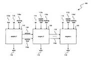
- FIG. 1is a schematic illustration of a working fluid delivery system 100 according to the present technology.
- the system 100includes a first engine 110 , a second engine 120 , and a third engine 130 .
- the third engine 130is labeled as “Engine n” because the system 100 can include any number of engines.
- a first engine 110 , second engine 120 and third engine 130are shown.
- the first engine 110can include an internal combustion engine that receives fuel 112 a , air 114 and a working fluid 116 a into a combustion chamber. As with conventional combustion chambers, the first engine 110 can burn the fuel 112 a and the air 114 to produce a combustion event.
- the engine 110can operate with fuel 112 a and air 114 under normal conditions until the temperature, pressure, or another variable causes a need for an injection of working fluid 116 a .
- a working fluid 116 acan be injected into a combustion chamber of the first engine 110 to cool the engine 110 and also to produce useful work 115 .
- the work 115can come from the combustion event, or from the working fluid 116 a , or a combination of the two.
- the working fluid 116 acan be a coolant fluid such as water, or a combustible substance such as ammonia, ethanol, methanol, gasoline, or any suitable fluid in any suitable mixture.
- the first engine 110can output an exhaust 118 from the engine which can be sent into the atmosphere, and/or passed forward into the second engine 120 .
- the working fluid 116 bnow hot from the combustion event and possibly in a different phase (e.g., gas), can be passed forward into the second engine 120 .
- the working fluid 116 bmay be altered chemically or otherwise as a result of passing through the first engine 110 .
- the working fluid 116 bis chosen according to how passing through the hot combustion chamber of the first engine 110 will affect the working fluid 116 b .
- different temperatures, pressures, and chemical constituencies within the combustion chambermay call for a selection from among various possible working fluids, or for some appropriate mixture of two or more working fluids, as suitable for use in the second engine 120 .
- the second engine 120can also receive air 114 , supplemental fuel 112 b , and additional working fluid 116 c .
- the working fluid 116 ccan be similar to the working fluid 116 a first injected into the first engine 110 , or the working fluid 116 b produced in the first engine 110 , or it can be a new species of working fluid.
- the second engine 120may be generally similar to the first engine 110 and can expand the fluid it receives and/or burn fuel, air and/or other substances in a series of combustion events to produce useful work 115 .
- the second engine 120is provided with another type of fuel generation system, including a thermo-chemical regeneration (“TCR”) system as described more fully in U.S.
- the second enginecan also be a turbine, can be a fuel cell, or an auxiliary system of the vehicle such an air conditioning system or an electricity generation system or any other auxiliary system.
- the third engine 130can similarly receive exhaust and/or working fluid 116 c from the second engine 120 , supplemental air 114 , fuel 112 c , and/or working fluid 116 d , and so on in a cascading series of engines.
- Each of the engines 110 , 120 , or 130can produce useful work from expansion of a working fluid and/or a combustion event, the working fluid expanding and/or changing phase, or any combination of such energy conversion events.
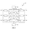
- FIG. 2is a schematic illustration of a further working fluid delivery system 200 according to embodiments of the present technology.
- the system 200can include in a first or primary engine 210 , a gate 250 a , a second engine 220 , a third engine 230 , and a fourth engine 240 ; each having respective gates, 250 b , 250 c , and 250 d .
- the engines 220 , 230 , and 240can be any type of engine, including a fuel cell, turbine, TCR unit or any suitable energy conversion system.
- the engines 220 , 230 , and 240are collectively referred to herein as secondary engines. It is to be appreciated that the system 200 can include any number of engines (primary or secondary) and gates in any suitable combination or series.
- the engine 210can receive fuel 212 , air 214 , and a working fluid 216 a and can combine these components and in a combustion cycle, can produce useful work 215 .
- the gate 250 acan receive the working fluid 216 b and the exhaust 218 from the engine 210 , and can adaptively direct the exhaust 218 and the working fluid 216 b to the second engine 220 , third engine 230 , fourth engine 240 , or as exhaust to the atmosphere. It is to be appreciated that any number of engines can be included in the system 200 .
- the system 200can also include a controller 252 operably coupled to the gate 250 a that can direct the fluids adaptively between the various engines as needed by the system 200 .
- the controller 252can monitor conditions in the various engines and distribute the working fluid 216 b among the engines as appropriate.
- the controller 252can include a predetermined delivery schedule.
- the controller 252can operate reactively based on sensed conditions within various combustion chambers and as needed by a given secondary engine under a given load.
- the engine 210may be used in various different environments and at different operating levels, and will produce varying amounts of working fluid, different temperatures and pressures, and different characteristics within the combustion chambers of the engine 210 .
- the working fluid 216 b and exhaust produced at differing loadscan be adaptively distributed advantageously to the secondary engines.
- the second engine 220may operate more efficiently on cooler working fluid 216 b that is produced when the engine 210 operates at a relatively low level.
- the third engine 230may run more efficiently on the type of working fluid 216 b and exhaust 218 produced by the first engine 210 when the first engine 210 operates at a very high level.
- the load on any of the secondary enginesmay dictate the type and/or quantity of working fluid 216 b delivered by the gate 250 a .
- the controller 252can include a priority listing of the engines 210 to resolve competing demands for resources.
- FIG. 3is a flowchart describing a method 300 of monitoring a process within a combustion engine and delivering a working fluid according to embodiments of the present technology.
- the method 300can be practiced with a sensing system for a combustion event as described more fully in U.S. patent application Ser. No. 13/027,170 entitled, “METHODS AND SYSTEMS FOR ADAPTIVELY COOLING COMBUSTION CHAMBERS IN ENGINES,” filed Feb. 14, 2011, which is incorporated herein by reference in its entirety.
- the sensing systemcan monitor many variables such as pressure, temperature, acoustic energy, optical measurements, and chemical conditions can be monitored within a combustion chamber.
- Step 330includes delivering working fluid to the combustion chamber to cool the combustion chamber.
- the type, amount, and timing of the working fluid deliverycan vary adaptively to optimize heat to work energy conversion purposes depending on other measured factors and design preferences.
- Step 340includes preparing subsequent engines to receive the working fluid as it flows downstream from a primary engine to a secondary engine. There is a slight lag between delivery to the primary engine and when the working fluid arrives at the secondary engine(s). In some embodiments, the status of the secondary engines can also be monitored. If there is an event requiring immediate delivery of working fluid or any other fluid where the lag is unacceptable, the working fluid can be delivered directly to the secondary engine as capabilities of a given configuration permit.
- the sampling rate of the measurementscan be sufficiently high that the conditions in the primary and secondary engines are monitored substantially in real time.
- an enginecan monitor temperature within individual combustion chambers, and using a controller or other control techniques, can carefully control the temperature of the engine and prevent each individual combustion chamber from exceeding a predetermined temperature limit, pressure limit, or another measured characteristic having a safe or desirable limit. Two or more measured characteristics can be measured together in step 320 . For example, temperature and pressure are generally related phenomena, as excessively high temperatures at high pressure are generally more concerning than high temperatures alone. Other combinations of variables can also trigger a delivery of working fluid to diffuse a situation.
- the decisioncan be based on a rate of temperature change as well as a value of temperature change. For example, if the difference between any two samplings of the temperature is greater than a threshold value, the method 300 can include inferring that the temperature is rising quickly and is likely to continue to rise. Accordingly, in some embodiments, even if the temperature is lower and is still within the acceptable range, if based on the current trend in the temperature and the engine it is likely that the temperature will exceed the threshold, the working fluid can be introduced into the chamber to cool the engine.
- the result of combusting a fuel in a conventional engineis that air or liquid is cooled by conduction of heat from the combustion chamber to exterior subsystems such as cooling fins, liquid coolants circulated by pumps to a fan cooled radiator, etc.
- the overall efficiency of converting the heat released by combustion into work delivered by the output shaftis typically about 28%.
- the traditional cooling system and exhaust systemsreject 72% of the heat released by combustion of which about 35 to 40% is removed by the air and/or liquid cooling system.
- the energy which is wasted from the combustion chamber by air and/or liquid cooling circulated in circuits outside of the combustion chamberis reduced or eliminated.
- Thisis accomplished by engine operation with a working fluid such as water that is injected during the power stroke or work-producing cycle of operation.
- the working fluidremoves heat from the combustion chamber to provide desired cooling and performs expansive work to replace the combustion of fuel as provided in each of the preceding five complete engine cycles.
- an average of one in six complete engine cyclesproduces the same amount of power without fuel combustion.
- Reduction in fuel consumptionis gained from expansion of a working fluid that cools the combustion chamber and performs work on an average of one cycle out of six.
- Another embodimentreduces or eliminates the energy removed from the combustion chamber by air and/or liquid cooling by operation with a working fluid selected from options such as water, a mixture of water and fuel or un-ignited and/or surplus fuel that removes heat from the combustion chamber and performs work by expansion.
- a working fluidselected from options such as water, a mixture of water and fuel or un-ignited and/or surplus fuel that removes heat from the combustion chamber and performs work by expansion.
- fuel potentialis exhausted from the first engine, it may be combusted to provide heat that is utilized by another engine that operates in conjunction with the first engine and/or such heat may drive endothermic reactions in a TCR system.
- a piston or rotary combustion primary engineis combined with a second engine such as a piston, rotary, or turbine expander or engine.
- a coolantselected from the group including water, a mixture of fuel and water, and non-aqueous liquids is injected by injector-igniter and/or into the combustion chamber during the power and/or exhaust cycles of a complete cycle that includes intake, compression, power and exhaust events. Ignition is eliminated or ignition timing is delayed to provide unburned fluid that performs the desired cooling of the first engine as it produces work and such fluid enters the second engine.
- the second enginehas the advantage of the coolant flow from the first engine through conduit to produce a higher mass flow rate and injection-igniter ignites any fuel that arrives from engine and may receive and combust additional fuel to boost power production as provided by controller. Operation according to this operational permutation provides much higher mass flow and/or temperature to TCR.
- FIG. 4illustrates a method 400 according to further embodiments of the present technology.
- a decisionis made whether working fluid is needed at a primary or a secondary engine.
- the needcan be based on a need for cooling, or to produce work based on the working fluid.
- the enginescan be operatively arranged in a cascading series and the working fluid can be designed to cool any one or more of the engines, and to produce useful work at any one or more of the engines.
- the working fluidincludes a hydrogen-rich substance that is to provide hydrogen to a process in a secondary engine. If the secondary engine needs hydrogen from the working fluid, the method 400 can continue at step 430 .
- FIG. 5is a partially schematic illustration of an engine and sensor system configured according to embodiments of the present technology.
- the system 500can include an engine 510 having a plurality of combustion chambers or cylinders 520 .
- a fluid delivery source 530can be configured to deliver fuel, air, and working fluid 550 through one or more pathways 532 to each of the combustion chambers or cylinders 520 .
- the system 500can also include a plurality of sensors 530 which can in some embodiments be individually coupled to combustion chambers 520 , and connected to a controller 540 .
- the individual combustion chambers 520can be equipped with sensing mechanisms that can monitor conditions within the combustion chambers 520 such as temperature, pressure, chemical constituents, light, acoustic energy, oxidant and/or fuel introduction and combustion event timing and patterns and virtually any other measurable characteristic.
- fuel, air and a working fluidcan be introduced into the combustion chambers through direct injection or through indirect injection.
- the sensors 530 , and the controller 540can monitor the combustion chambers 520 independently such that information such as the temperature and/or pressure etc., of each individual cylinder 520 can be monitored and the temperature and/or pressure can be controlled independent of other combustion chambers.
- differing amounts of working fluid, fuel, air and other substancescan be delivered to individual combustion chambers according to the temperature and/or pressure within each individual combustion chamber 520 . Accordingly the heat production and the combustion event within the individual combustion chambers can be individually monitored which leads to a more efficient use of working fluid, including better control of temperature and/or pressure within the engine 510 as compared to conventional combustion control in engine operations.
- FIG. 6is a schematic block diagram of a four stroke combustion cycle and working fluid injection routine 600 configured in accordance with embodiments of the present disclosure.
- the description of the injection routine 600includes many alternative methods and timings of injecting working fluid and other materials into the combustion chamber. It is to be appreciated that any suitable combination of these alternatives can be used according to the needs of a particular engine.
- the injection routine 600can be performed in a single combustion chamber, or in several cooperative combustion chambers forming a single engine.
- the injection routine 600can be performed generally independently in individual chambers of an engine.
- the engine of the present disclosurecan operate with a four-stroke combustion engine including an intake stroke 610 , a compression stroke 620 , a combustion stroke 630 and an exhaust stroke 640 .
- a combustion chamber having one or more intake and one or more exhaust valves and a pistongenerally involves a piston moving away from top dead center (“TDC”) and toward bottom dead center (“BDC”) so as to provide the maximum space for oxidant 612 (e.g., air) entry into the interior volume of the combustion chamber.
- Oxidant entrymay be below, at, or above the ambient pressure of the atmosphere depending upon factors such as the impedance to air flow and application of oxidant inducing or pressurizing subsystems such as a blower or turbocharger (not shown).
- other substancessuch as fuel 614 and/or another working fluid 616 a are introduced along with the oxidant into the chamber.
- one or more fuel injectorscan indirectly or directly inject fuel and/or other substances into the combustion chamber during the intake stroke 610 .
- the compression stroke 620is generally when the piston moves from BDC back toward TDC so as to reduce the volume of the combustion chamber and increase pressure in the combustion chamber in preparation for a combustion event.
- one or more fuel injectorscan inject fuel and/or other substances into the combustion chamber in the compression stroke 620 .
- one or more fuel injectorscan inject fuel and/or other substances into the combustion chamber in the combustion stroke 630 .
- the pistonagain moves from TDC back toward BDC to enlarge the volume of the combustion chamber under the pressure caused by one or more combustion events.
- the exhaust strokeis similar to the compression stroke in that the piston moves from BDC to TDC so as to reduce the volume of the combustion chamber.
- one or more fuel injectorscan inject fuel and/or other substances into the combustion chamber. In this stroke the residual combustion fluids and substances are removed from the chamber. The process can repeat continuously.
- a fuel and/or another working fluidcan be injected into the combustion chamber according to the injection routine 600 at any point in the four-stroke cycle as will be described herein in more detail.
- the individual working fluids 616 a - 616 m referred to belowgenerally relate to similar working fluids, altered in some way such as by heating, phase change, and/or phase change and/or respeciation such as (CH3OH+ ⁇ CO+2H2).
- a single quantity of working fluidmay be described as working fluid 616 a in one portion of the disclosure, but after passing through a process within the combustion chamber, the working fluid 616 a has changed in some way and accordingly is now referred to as working fluid 616 b , 616 c , etc.
- the working fluids 616 a - 616 mcan be similar to the working fluids described above, including coolants or fuels or any other type of working fluid.
- the fuel, working fluids, and other substancescan be introduced into the combustion chamber by a fuel injector, such as an indirect injector or a direct injector.
- a fuel injectorsuch as an indirect injector or a direct injector.
- An indirect injectoris one that injects fuel into an oxidant intake manifold or passageway or other port just outside the combustion chamber, and relies on positive pressure in the manifold or negative pressure in the chamber to draw the oxidant and fuel into the combustion chamber.
- a direct injectorgenerally injects fuel and/or other substances into the combustion chamber directly, through a path independent from an air manifold or any other access point to the chamber.
- one or more fuel injectorscan include multiple independent paths through which different fluids and/or fluid mixtures can be injected into the combustion chamber independently. Examples of such fuel injectors are given in U.S.
- oxidantsuch as air 612 , fuel 614 , and a working fluid 616 a can be introduced into the combustion chamber.
- Introducing the working fluid 616 a into the combustion chamber at this stage of the processcan be performed using indirect injection or direct injection. Accordingly, this portion of the routine 600 can be used in a retrofit installation using an existing combustion engine without a direct injection system as well as in an engine specifically designed for such a routine 600 .
- Injecting working fluid during other portions of the energy cycle, such as the compression stroke 620 , combustion stroke 630 or exhaust stroke 640is preferably performed with a direct injector.
- the working fluidcan cool components of the combustion chamber of an engine at any time such as during the intake stroke 610 , compression stroke 620 , power stroke 630 , or exhaust stroke 640 and commensurately or subsequently (later) perform useful work as will be described below.
- the fuel 614 that has been introduced and/or working fluid 616 bremain in the chamber into the compression stroke 620 .
- the working fluid 616 bmay now be heated due to exposure to elevated temperature components and/or compression induced heating within the combustion chamber.
- the working fluid 616 bcan be changed chemically or otherwise by exposure to the heated combustion chamber, such as by releasing or preparing to release fuel components such as hydrogen, or by changing phase from a liquid to a gas.
- Additional fuel and/or working fluid 616 ccan be introduced during the compression cycle 620 .
- the working fluid 616 ccan be generally similar to the working fluid 616 a , or it can have a different phase or chemical makeup. Due to exposure to heat in the combustion chamber, at least a portion of any liquid fuel and/or working fluid 616 b has changed phase to a vapor or gas to perform work in the power cycle operation.
- controller 540provides for maintenance of the temperature of critical components within a desired temperature range by injection of working fluid for performing such work producing and cooling events and benefits on a certain frequency such as every 3rd, 4th, 5th, . . . or Nth cyclic event such as in the power stroke.
- controller 540provides for maintenance of the temperature of critical combustion chamber components within a desired temperature range by injection of fuel and/or working fluid for performing such cooling events and benefits on a certain frequency such as every 3rd, 4th, 5th, . . . or Nth cyclic event such as in the intake, compression, power and/or exhaust strokes.
- fuel 614 and/or the working fluid 616 ais introduced during the intake cycle including operation with restricted air intake that is normally delivered, to perform cooling and work production.
- fuel 614 and/or working fluid 616 hcan be introduced to perform cooling and work production functions 632 .
- the routine 600can direct one or more combustion chambers in the engine to change at least temporarily to this two-stroke pattern, and when heat levels are again lowered to desirable levels, the routine 600 can restore the four-stroke pattern of intake, compression, combustion, and exhaust.
- some combination of fuel 614 , working fluid 616 f , and vaporized working fluid 616 gcan remain in the combustion chamber.
- the mixtureis ignited and burned to produce useful work 632 .
- a portion of the work 632can come from burning the fuel; another portion of the work 634 can come from the vaporized working fluid 616 g exerting pressure on the piston in the chamber.
- Additional working fluid 616 hcan be injected into the chamber before the combustion event, during the combustion event, or after the combustion event.
- working fluid 616 i and vaporized working fluid 616 jare carried from in the combustion chamber to perform in other valuable events.
- the amount of vaporized working fluid 616 j and liquid working fluid 616 ican be varied according to the temperature in the engine, the characteristics of the working fluid, the combustion event, the fuel, and virtually any other variable in the engine cycle.
- Working fluid 616 kcan also be injected during the exhaust stroke 640 to further cool the engine, or in preparation for a downstream process in a secondary engine.
- a portion of the working fluid 616 l and optionally exhaustcan be delivered to a TCR unit 622 to develop and/or increase the chemical fuel potential energy of the fuel and/or the working fluid 616 l and exhaust.
- a portion of the working fluid 616 mcan be delivered to a secondary engine 650 as described above, such as a turbine, a fuel cell, another combustion engine, or any other suitable engine that can extract energy from the working fluid 616 m.
- the injection routine 600can be used with virtually any suitable fuel type, such as diesel, gasoline, methanol, ethanol, ethane, propane, butane, natural gas, ammonia or cryogenic fuels such as liquid hydrogen or methane, etc.
- diesel and/or gasoline fuelsit is generally preferable to inject the working fluid during the power stroke 620 or the exhaust stroke 640 .
- a gaseous fuelsuch as hydrogen, methane, ammonia, or natural gas
- the working fluidcan be injected at any portion of the cycle: the intake stroke 610 , the compression stroke 620 , the combustion stroke 630 , or the exhaust stroke 640 .
- cryogenic fuelssuch as liquid hydrogen or methane it is preferable to inject during the combustion stroke 630 , or the exhaust stroke 640 depending upon the type and number of events the exhaust will be directed to perform.
- the type of fuel and/or working fluidcan be chosen based on its ability to carry heat or other components that may be formed downstream to the secondary engine 650 or TCR 622 .
- Working fluidshave different heat capacities and, accordingly, are more or less able to absorb and carry heat or process energy forward to another process. For example, where it is desired to quickly absorb low amounts of heat, a working fluid with a relatively low specific heat can be used to quickly absorb heat. Otherwise, if there is a greater amount of heat to be carried forward, a working fluid with a higher specific heat can be used.
- the working fluidcan also be chosen based on the amount of heat and other energy that may be needed downstream in the secondary engine(s) 650 or in the TCR units 622 .
- a secondary engine 650may operate a certain process for which a working fluid 616 m is expected to yield hydrogen or other components for the process.
- the type of working fluid used in the injection routine 600 in the primary enginecan be chosen such that the working fluid 616 m can cool the primary engine and/or perform work in the primary engine without yielding the hydrogen, but in the process of the secondary engine 650 , the working fluid 616 m can release the hydrogen due to favorable conditions in the secondary engine 650 (e.g., temperature, pressure, or chemical environment within the secondary engine 650 ).
- a feed stock or working fluid comprising wet-black methanolcan initially be converted to hydrogen and carbon monoxide by endothermic heat from the exhaust and by an electric resistance supplemental heater.
- liquid feed stockcan be switched directly to the injector to gain the benefit of the phase change and higher heat removal capacity.
- Another feedstockcan be ammonia and/or ammonium hydroxide mixtures: 2NH3+HEAT-->N2+3H2
- liquid ammoniacan be switched directly to the injector to gain the benefit of the phase change for higher heat removal capacity.
- any number of primary engines and secondary enginescan be used in a cascading series.
- any single enginecan be considered a primary engine or a secondary engine depending on how they exchange fluids according to a given configuration.
- the working fluidcan be any suitable fluid and is not limited to specific examples listed herein.
- the engine systemsmay include alternative configurations than those shown and described and still be within the spirit of the disclosure.
Landscapes
- Engineering & Computer Science (AREA)
- Chemical & Material Sciences (AREA)
- Combustion & Propulsion (AREA)
- Mechanical Engineering (AREA)
- General Engineering & Computer Science (AREA)
- Oil, Petroleum & Natural Gas (AREA)
- Biodiversity & Conservation Biology (AREA)
- Biotechnology (AREA)
- Botany (AREA)
- Sustainable Development (AREA)
- Sustainable Energy (AREA)
- Life Sciences & Earth Sciences (AREA)
- Output Control And Ontrol Of Special Type Engine (AREA)
- Engine Equipment That Uses Special Cycles (AREA)
- Combustion Methods Of Internal-Combustion Engines (AREA)
Abstract
Description
- cooling fan operation
- water pump drive
- propulsion of the additional masses including cooling jacket and/or fin materials, inventory of coolant, coolant overflow tank, coolant overflow tank filter system, coolant hoses to and from the cooling jacket of the engine, coolant hose connectors and fittings, thermostat housing, thermostat, water pump, water pump drive belt idler-tensioner assembly, radiator, radiator shroud, air fan, fan drive belt, fan belt idler-tensioner assembly, etc.;
- drag caused by frontal area required (or equivalent fan energy required) to dissipate 35 to 40% of the heat released by the fuel combustion as required by conventional subsystems to minimize the thermal cycling degradation of the combustion chamber materials.
- Larger potential turn-down ratio by various selections of operational permutations to meet a larger variety of power requirements
- Additional mass flow of expansive working fluid coolant from first engine to the second engine enables greater work capacity and higher efficiency by the second engine.
- Much faster response provided by direct injection of non-combustible coolant working fluid and/or by operation with a fuel selection without ignition and/or operation of the first engine with a cooling cycle based on incomplete combustion resulting from adaptive ignition timing control and/or the use of surplus fuel enables much greater power production than allowed by conventional cooling systems.
CH3OH+H2O+C+HEAT-->2CO+3H2
2NH3+HEAT-->N2+3H2
- 1) Conventional cooling systems including air and liquid cooling systems such as systems with temperature limitations based on rubber hoses, water-pump seals, coolants, thermostats, gaskets, radiators etc., require sacrifice of high temperature heat from the combustion chamber and consequently assured waste of energy by reducing the thermodynamic quality to the range of about 160 F to 240 F (virtually eliminating the availability for doing useful work). The current cycle of operation utilizes the highest temperature available from the surface materials of the combustion chamber and extracts heat from these surfaces to produce working fluid temperatures of 500 F to 1200 F to enable faster and more effective maintenance of desired operating temperatures by intermittent cooling to provide highly desirable power-stroke expansions of hot working fluid gases and production of as much or more torque as combustion of fuel.
- 2) Steam engines powering ships, heavy locomotives, steam-shovels, pile-drivers, automobiles etc., have a long service lives for producing highly desirable torque and operational capabilities by heating water in a boiler to form steam which is taken to one or more drivers with piston and cylinder assemblies to produce thrust that is converted into rotary motion at the desired torque. A typical temperature and pressure of the steam from heavy coal-fired locomotive boilers is 190 PSI at 383 F to produce 8,000 horsepower to pull 100 heavily loaded freight cars at speeds up to 100 MPH or as permitted by track design and maintenance. In 1906 the Land Speed Record was established by a Stanley steam car as it achieved 127 mph at Ormond Beach, Fla. In comparison the current cycle using water as a working fluid can readily utilize a diesel or gasoline engine's existing system including cylinders, pistons, crankshafts etc to produce and expand steam from temperatures of 400 F to 600 F and pressures of 200 to 500 PSI and provide highly desirable torque and power along with maintenance of the combustion chamber component temperatures within the same range as provided by conventional cooling systems.
- 3) It is desirable to operate current system in conjunction with thermochemical regeneration (TCR) and/or turbochargers, turbogenerators, gas-combustion turbines, and/or working fluid recovery systems. Thus work production and/or extraction of heat to drive endothermic chemical processes reduces the temperature of the working fluid to greatly increase the density and reduce the vapor pressure to cause condensation for convenient storage and/or immediate reuse in the current cycle.
Claims (14)
Priority Applications (2)
| Application Number | Priority Date | Filing Date | Title |
|---|---|---|---|
| US13/584,775US8683988B2 (en) | 2011-08-12 | 2012-08-13 | Systems and methods for improved engine cooling and energy generation |
| US13/766,710US20130291826A1 (en) | 2011-08-12 | 2013-02-13 | Systems and vehicles incorporating improved engine cooling and energy generation |
Applications Claiming Priority (2)
| Application Number | Priority Date | Filing Date | Title |
|---|---|---|---|
| US201161523157P | 2011-08-12 | 2011-08-12 | |
| US13/584,775US8683988B2 (en) | 2011-08-12 | 2012-08-13 | Systems and methods for improved engine cooling and energy generation |
Related Child Applications (1)
| Application Number | Title | Priority Date | Filing Date |
|---|---|---|---|
| US13/766,710Continuation-In-PartUS20130291826A1 (en) | 2011-08-12 | 2013-02-13 | Systems and vehicles incorporating improved engine cooling and energy generation |
Publications (2)
| Publication Number | Publication Date |
|---|---|
| US20130206082A1 US20130206082A1 (en) | 2013-08-15 |
| US8683988B2true US8683988B2 (en) | 2014-04-01 |
Family
ID=47715670
Family Applications (1)
| Application Number | Title | Priority Date | Filing Date |
|---|---|---|---|
| US13/584,775Expired - Fee RelatedUS8683988B2 (en) | 2011-08-12 | 2012-08-13 | Systems and methods for improved engine cooling and energy generation |
Country Status (4)
| Country | Link |
|---|---|
| US (1) | US8683988B2 (en) |
| EP (1) | EP2742218A4 (en) |
| CN (1) | CN103890343B (en) |
| WO (1) | WO2013025657A2 (en) |
Cited By (1)
| Publication number | Priority date | Publication date | Assignee | Title |
|---|---|---|---|---|
| US9410474B2 (en) | 2010-12-06 | 2016-08-09 | Mcalister Technologies, Llc | Integrated fuel injector igniters configured to inject multiple fuels and/or coolants and associated methods of use and manufacture |
Families Citing this family (3)
| Publication number | Priority date | Publication date | Assignee | Title |
|---|---|---|---|---|
| CN113188851A (en)* | 2021-01-07 | 2021-07-30 | 中国航发沈阳发动机研究所 | Ultra-high temperature high pressure gas sampler |
| CN113982788A (en)* | 2021-11-02 | 2022-01-28 | 厦门大学 | Ammonia liquid supply system of ammonia-mixed diesel engine |
| CN114577463B (en)* | 2022-05-05 | 2022-08-12 | 西安航天动力研究所 | Reliability evaluation method of bolt injector |
Citations (385)
| Publication number | Priority date | Publication date | Assignee | Title |
|---|---|---|---|---|
| US1451384A (en) | 1920-04-19 | 1923-04-10 | Whyte John | Solenoid-controlled fuel injection and ignition valve |
| US1765237A (en) | 1928-02-17 | 1930-06-17 | Fred H King | Triple-cam-drive gasoline engine |
| US2068038A (en) | 1933-08-16 | 1937-01-19 | Floyd S Prothero | Internal combustion engine |
| US2215793A (en) | 1938-11-29 | 1940-09-24 | Mayes Graham | Internal combustion engine |
| US2255203A (en) | 1940-02-28 | 1941-09-09 | Wright Aeronautical Corp | Fuel injection spark plug |
| US2441277A (en) | 1945-10-13 | 1948-05-11 | American Bosch Corp | Combined injector nozzle and spark plug |
| US2721100A (en) | 1951-11-13 | 1955-10-18 | Jr Albert G Bodine | High frequency injector valve |
| US3058453A (en) | 1960-02-15 | 1962-10-16 | Walker Mfg Co | Fuel injector-igniter |
| US3060912A (en) | 1960-02-15 | 1962-10-30 | Walker Mfg Co | Fuel injector-igniter |
| US3081758A (en) | 1960-05-02 | 1963-03-19 | Walker Mfg Co | Pressure actuated fuel injector |
| US3243335A (en) | 1963-03-13 | 1966-03-29 | Samuel P Faile | Ceramic product and process of producing it |
| GB1038490A (en) | 1963-02-18 | 1966-08-10 | Papst Hermann | Fuel injection nozzles for internal combustion engines |
| US3286164A (en) | 1962-05-18 | 1966-11-15 | Mobil Oil Corp | Systems for detection and automatic registration of preignition ionization potentials in internal combustion engines |
| US3373724A (en) | 1964-02-10 | 1968-03-19 | Papst Hermann | Fuel injection and ignition device for internal combustion engines |
| US3391680A (en) | 1965-09-01 | 1968-07-09 | Physics Internat Company | Fuel injector-ignitor system for internal combustion engines |
| US3520961A (en) | 1967-05-12 | 1970-07-21 | Yuken Ind Co Ltd | Method for manufacturing ceramic articles |
| US3594877A (en) | 1969-10-24 | 1971-07-27 | Yuken Kogyo Co Ltd | Apparatus for manufacturing ceramic articles |
| US3608050A (en) | 1969-09-12 | 1971-09-21 | Union Carbide Corp | Production of single crystal sapphire by carefully controlled cooling from a melt of alumina |
| US3689293A (en) | 1970-07-08 | 1972-09-05 | Corning Glass Works | Mica glass-ceramics |
| US3745887A (en) | 1971-03-31 | 1973-07-17 | Temco Contact Ltd | Engine power unit |
| US3926169A (en) | 1974-06-21 | 1975-12-16 | Fuel Injection Dev Corp | Combined fuel vapor injector and igniter system for internal combustion engines |
| US3931438A (en) | 1971-11-08 | 1976-01-06 | Corning Glass Works | Differential densification strengthening of glass-ceramics |
| US3960995A (en) | 1970-05-13 | 1976-06-01 | Kourkene Jacques P | Method for prestressing a body of ceramic material |
| US3976039A (en)* | 1973-06-06 | 1976-08-24 | Regie Nationale Des Usines Renault | Internal combustion engine with stratified charge |
| US3997352A (en) | 1975-09-29 | 1976-12-14 | Corning Glass Works | Mica-spodumene glass-ceramic articles |
| US4020803A (en) | 1975-10-30 | 1977-05-03 | The Bendix Corporation | Combined fuel injection and intake valve for electronic fuel injection engine systems |
| US4041910A (en) | 1975-04-02 | 1977-08-16 | The United States Of America As Represented By The Administrator Of The National Aeronautics And Space Administration | Combustion engine |
| US4062338A (en) | 1976-04-16 | 1977-12-13 | Energiagazdalkodasi Intezet | Steam cooling system for internal combustion engines |
| US4066046A (en) | 1974-07-29 | 1978-01-03 | Mcalister Roy E | Method and apparatus for fuel injection-spark ignition system for an internal combustion engine |
| US4095580A (en) | 1976-10-22 | 1978-06-20 | The United States Of America As Represented By The United States Department Of Energy | Pulse-actuated fuel-injection spark plug |
| US4105004A (en) | 1975-11-04 | 1978-08-08 | Kabushiki Kaisha Toyota Chuo Kenkyusho | Ultrasonic wave fuel injection and supply device |
| US4116389A (en) | 1976-12-27 | 1978-09-26 | Essex Group, Inc. | Electromagnetic fuel injection valve |
| US4122816A (en) | 1976-04-01 | 1978-10-31 | The United States Of America As Represented By The Administrator Of The National Aeronautics And Space Administration | Plasma igniter for internal combustion engine |
| US4135481A (en)* | 1976-11-26 | 1979-01-23 | Cornell Research Foundation, Inc. | Exhaust gas recirculation pre-stratified charge |
| US4172921A (en) | 1974-05-17 | 1979-10-30 | Jenaer Glaswerk Schott & Gen. | Fireproof glass |
| US4183467A (en) | 1977-06-22 | 1980-01-15 | Lucas Industries Limited | Fluid control valves |
| US4203393A (en) | 1979-01-04 | 1980-05-20 | Ford Motor Company | Plasma jet ignition engine and method |
| US4293188A (en) | 1980-03-24 | 1981-10-06 | Sperry Corporation | Fiber optic small displacement sensor |
| US4330732A (en) | 1980-03-14 | 1982-05-18 | Purification Sciences Inc. | Plasma ceramic coating to supply uniform sparking action in combustion engines |
| US4332223A (en) | 1980-08-29 | 1982-06-01 | Dalton James M | Plasma fuel ignitors |
| US4364342A (en) | 1980-10-01 | 1982-12-21 | Ford Motor Company | Ignition system employing plasma spray |
| US4364363A (en) | 1980-01-18 | 1982-12-21 | Toyota Jidosha Kogyo Kabushiki Kaisha | Electronically controlling, fuel injection method for internal combustion engine |
| US4368707A (en) | 1976-11-22 | 1983-01-18 | Fuel Injection Development Corporation | Adaptive charge forming system for controlling the air/fuel mixture supplied to an internal combustion engine |
| US4377455A (en) | 1981-07-22 | 1983-03-22 | Olin Corporation | V-Shaped sandwich-type cell with reticulate electodes |
| US4382189A (en) | 1979-05-25 | 1983-05-03 | Wilson John B | Hydrogen supplemented diesel electric locomotive |
| US4381740A (en) | 1980-05-05 | 1983-05-03 | Crocker Alfred J | Reciprocating engine |
| US4391914A (en) | 1982-06-14 | 1983-07-05 | Corning Glass Works | Strengthened glass-ceramic article and method |
| US4413474A (en) | 1982-07-09 | 1983-11-08 | Moscrip William M | Mechanical arrangements for Stirling-cycle, reciprocating thermal machines |
| US4432310A (en) | 1979-05-03 | 1984-02-21 | Leonard J. E. Waller | Parallel cylinder internal combustion engine |
| US4448160A (en) | 1982-03-15 | 1984-05-15 | Vosper George W | Fuel injector |
| US4469160A (en) | 1981-12-23 | 1984-09-04 | United Technologies Corporation | Single crystal solidification using multiple seeds |
| US4483485A (en) | 1981-12-11 | 1984-11-20 | Aisan Kogyo kabuskiki Kaisha | Electromagnetic fuel injector |
| US4511612A (en) | 1981-08-21 | 1985-04-16 | Motoren-Und Turbinen-Union Munchen Gmbh | Multiple-layer wall for a hollow body and method for manufacturing same |
| US4528270A (en) | 1982-11-02 | 1985-07-09 | Kabushiki Kaisya Advance Kaihatsu Kenkyujo | Electrochemical method for detection and classification of microbial cell |
| US4536452A (en) | 1983-10-24 | 1985-08-20 | Corning Glass Works | Spontaneously-formed machinable glass-ceramics |
| US4553508A (en) | 1981-04-27 | 1985-11-19 | Stinebaugh Donald E | Internal combustion engine |
| US4567857A (en) | 1980-02-26 | 1986-02-04 | The United States Of America As Represented By The Administrator Of The National Aeronautics And Space Administration | Combustion engine system |
| US4574037A (en) | 1983-04-12 | 1986-03-04 | Kanegafuchi Kagaku Kogyo Kabushiki Kaisha | Vertical type electrolytic cell and electrolytic process using the same |
| DE3443022A1 (en) | 1984-11-26 | 1986-05-28 | Walter Neumarkt am Wallersee Dolzer | Transistor ignition system |
| US4677960A (en) | 1984-12-31 | 1987-07-07 | Combustion Electromagnetics, Inc. | High efficiency voltage doubling ignition coil for CD system producing pulsed plasma type ignition |
| US4684211A (en) | 1985-03-01 | 1987-08-04 | Amp Incorporated | Fiber optic cable puller |
| US4688538A (en) | 1984-12-31 | 1987-08-25 | Combustion Electromagnetics, Inc. | Rapid pulsed multiple pulse ignition and high efficiency power inverter with controlled output characteristics |
| US4700891A (en) | 1985-10-02 | 1987-10-20 | Robert Bosch Gmbh | Electromagnetically actuatable fuel injection valve |
| US4716874A (en) | 1985-09-27 | 1988-01-05 | Champion Spark Plug Company | Control for spark ignited internal combustion engine |
| US4733646A (en) | 1986-04-30 | 1988-03-29 | Aisin Seiki Kabushiki Kaisha | Automotive ignition systems |
| US4736718A (en) | 1987-03-19 | 1988-04-12 | Linder Henry C | Combustion control system for internal combustion engines |
| US4742265A (en) | 1986-11-12 | 1988-05-03 | Ford Motor Company | Spark plug center electrode of alloy material including aluminum and chromium |
| US4760818A (en) | 1986-12-16 | 1988-08-02 | Allied Corporation | Vapor phase injector |
| US4760820A (en) | 1983-07-20 | 1988-08-02 | Luigi Tozzi | Plasma jet ignition apparatus |
| US4774919A (en) | 1986-09-08 | 1988-10-04 | Yamaha Hatsudoki Kabushiki Kaisha | Combustion chamber importing system for two-cycle diesel engine |
| US4774914A (en) | 1985-09-24 | 1988-10-04 | Combustion Electromagnetics, Inc. | Electromagnetic ignition--an ignition system producing a large size and intense capacitive and inductive spark with an intense electromagnetic field feeding the spark |
| US4777925A (en) | 1988-02-22 | 1988-10-18 | Lasota Lawrence | Combined fuel injection-spark ignition apparatus |
| US4834033A (en) | 1986-10-31 | 1989-05-30 | Larsen Melvin J | Apparatus and method for a balanced internal combustion engine coupled to a drive shaft |
| US4841925A (en) | 1986-12-22 | 1989-06-27 | Combustion Electromagnetics, Inc. | Enhanced flame ignition for hydrocarbon fuels |
| US4884533A (en) | 1986-06-04 | 1989-12-05 | Antonio Risitano | Method of and an arrangement for burning a liquid or gaseous fuel in a combustion chamber of an internal combustion engine |
| US4922883A (en) | 1987-10-29 | 1990-05-08 | Aisin Seiki Kabushiki Kaisha | Multi spark ignition system |
| US4932263A (en) | 1989-06-26 | 1990-06-12 | General Motors Corporation | Temperature compensated fiber optic pressure sensor |
| US4967708A (en) | 1987-09-17 | 1990-11-06 | Robert Bosch Gmbh | Fuel injection valve |
| US4977873A (en) | 1989-06-08 | 1990-12-18 | Clifford L. Elmore | Timing chamber ignition method and apparatus |
| US4979406A (en) | 1979-05-03 | 1990-12-25 | Walter J. Monacelli | Cam with sinusoidal cam lobe surfaces |
| US4982708A (en) | 1989-06-22 | 1991-01-08 | Robert Bosch Gmbh | Fuel injection nozzle for internal combustion engines |
| US5034852A (en) | 1989-11-06 | 1991-07-23 | Raytheon Company | Gasket for a hollow core module |
| US5035360A (en) | 1990-07-02 | 1991-07-30 | The University Of Toronto Innovations Foundation | Electrically actuated gaseous fuel timing and metering device |
| US5036669A (en) | 1989-12-26 | 1991-08-06 | Caterpillar Inc. | Apparatus and method for controlling the air/fuel ratio of an internal combustion engine |
| US5055435A (en) | 1987-03-24 | 1991-10-08 | Ngk Insulators, Ltd. | Ceramic materials to be insert-cast |
| US5056496A (en) | 1989-03-14 | 1991-10-15 | Nippondenso Co., Ltd. | Ignition system of multispark type |
| US5069189A (en) | 1989-06-27 | 1991-12-03 | Sanshin Kogyo Kabushiki Kaisha | Fuel injector system for internal combustion engine |
| US5072617A (en) | 1990-10-30 | 1991-12-17 | The United States Of America As Represented By The United States Department Of Energy | Fiber-optic liquid level sensor |
| US5076223A (en) | 1990-03-30 | 1991-12-31 | Board Of Regents, The University Of Texas System | Miniature railgun engine ignitor |
| US5095742A (en) | 1990-08-24 | 1992-03-17 | Ford Motor Company | Determining crankshaft acceleration in an internal combustion engine |
| US5107673A (en) | 1988-08-09 | 1992-04-28 | Hitachi, Ltd. | Method for detecting combustion conditions in combustors |
| US5109817A (en) | 1990-11-13 | 1992-05-05 | Altronic, Inc. | Catalytic-compression timed ignition |
| US5125366A (en)* | 1990-10-11 | 1992-06-30 | Hobbs Cletus L | Water introduction in internal combustion engines |
| US5131376A (en) | 1991-04-12 | 1992-07-21 | Combustion Electronics, Inc. | Distributorless capacitive discharge ignition system |
| US5150682A (en) | 1990-09-26 | 1992-09-29 | S.E.M.T. Pielstick | Method of monitoring emission of nitrogen oxides by an internal combustion engine |
| US5193515A (en) | 1991-03-12 | 1993-03-16 | Aisin Seiki Kabushiki Kaisha | Ignition system for an engine |
| US5207208A (en) | 1991-09-06 | 1993-05-04 | Combustion Electromagnetics Inc. | Integrated converter high power CD ignition |
| US5211142A (en) | 1990-03-30 | 1993-05-18 | Board Of Regents, The University Of Texas System | Miniature railgun engine ignitor |
| US5220901A (en) | 1991-10-09 | 1993-06-22 | Mitsubishi Denki Kabushiki Kaisha | Capacitor discharge ignition system with inductively extended discharge time |
| US5222481A (en) | 1991-06-26 | 1993-06-29 | Fuji Jukogyo Kabushiki Kaisha | Fuel injection control system for an internal combustion engine |
| US5267601A (en) | 1988-11-10 | 1993-12-07 | Lanxide Technology Company, Lp | Method for forming a metal matrix composite body by an outside-in spontaneous infiltration process, and products produced thereby |
| US5297518A (en) | 1992-08-10 | 1994-03-29 | Cherry Mark A | Mass controlled compression timed ignition method and igniter |
| US5305360A (en) | 1993-02-16 | 1994-04-19 | Westinghouse Electric Corp. | Process for decontaminating a nuclear reactor coolant system |
| US5329606A (en) | 1992-02-06 | 1994-07-12 | Alcatel Kabel Norge As | Fiber optic cable |
| US5328094A (en) | 1993-02-11 | 1994-07-12 | General Motors Corporation | Fuel injector and check valve |
| US5343699A (en) | 1989-06-12 | 1994-09-06 | Mcalister Roy E | Method and apparatus for improved operation of internal combustion engines |
| US5377633A (en) | 1993-07-12 | 1995-01-03 | Siemens Automotive L.P. | Railplug direct injector/ignitor assembly |
| US5390546A (en) | 1993-07-01 | 1995-02-21 | Wlodarczyk; Marek T. | Fiber optic diaphragm sensors for engine knock and misfire detection |
| US5392745A (en) | 1987-02-20 | 1995-02-28 | Servojet Electric Systems, Ltd. | Expanding cloud fuel injecting system |
| US5394838A (en) | 1992-07-24 | 1995-03-07 | American Fuel Systems, Inc. | Vaporized fuel injection system |
| US5394852A (en) | 1989-06-12 | 1995-03-07 | Mcalister; Roy E. | Method and apparatus for improved combustion engine |
| US5421195A (en) | 1993-07-01 | 1995-06-06 | Wlodarczyk; Marek T. | Fiber optic microbend sensor for engine knock and misfire detection |
| US5421299A (en) | 1992-08-10 | 1995-06-06 | Cherry; Mark A. | Compression timed pre-chamber flame distributing igniter for internal combustion engines |
| US5435286A (en) | 1994-05-02 | 1995-07-25 | Cummins Engine Company, Inc. | Ball link assembly for vehicle engine drive trains |
| US5439532A (en) | 1992-06-30 | 1995-08-08 | Jx Crystals, Inc. | Cylindrical electric power generator using low bandgap thermophotovolatic cells and a regenerative hydrocarbon gas burner |
| US5456241A (en) | 1993-05-25 | 1995-10-10 | Combustion Electromagnetics, Inc. | Optimized high power high energy ignition system |
| US5475772A (en) | 1994-06-02 | 1995-12-12 | Honeywell Inc. | Spatial filter for improving polarization extinction ratio in a proton exchange wave guide device |
| US5497744A (en) | 1993-11-29 | 1996-03-12 | Toyota Jidosha Kabushiki Kaisha | Fuel injector with an integrated spark plug for a direct injection type engine |
| US5517961A (en) | 1995-02-27 | 1996-05-21 | Combustion Electromagnetics, Inc. | Engine with flow coupled spark discharge |
| US5531199A (en) | 1992-05-11 | 1996-07-02 | United Fuels Limited | Internal combustion engines |
| US5549746A (en) | 1993-09-24 | 1996-08-27 | General Electric Company | Solid state thermal conversion of polycrystalline alumina to sapphire using a seed crystal |
| US5568801A (en) | 1994-05-20 | 1996-10-29 | Ortech Corporation | Plasma arc ignition system |
| US5584490A (en) | 1994-08-04 | 1996-12-17 | Nippon Gasket Co., Ltd. | Metal gasket with coolant contact areas |
| US5588299A (en) | 1993-05-26 | 1996-12-31 | Simmonds Precision Engine Systems, Inc. | Electrostatic fuel injector body with igniter electrodes formed in the housing |
| US5605125A (en) | 1994-11-18 | 1997-02-25 | Yaoita; Yasuhito | Direct fuel injection stratified charge engine |
| US5608832A (en) | 1993-04-14 | 1997-03-04 | Siemens Aktiengesellschaft | Optical cable having a plurality of light waveguides arranged in a prescribed structure and having different mechanical sensitivies |
| US5607106A (en) | 1994-08-10 | 1997-03-04 | Cummins Engine Company | Low inertia, wear-resistant valve for engine fuel injection systems |
| US5662389A (en) | 1996-09-10 | 1997-09-02 | New York Air Brake Corporation | Variable load EP brake control system |
| US5676026A (en) | 1994-09-20 | 1997-10-14 | Honda Giken Kogyo Kabushiki Kaisha | Hydraulic pressure control system |
| US5694761A (en) | 1993-07-07 | 1997-12-09 | Griffin, Jr.; Arthur T. | Combustor cooling for gas turbine engines |
| US5699253A (en) | 1995-04-05 | 1997-12-16 | Ford Global Technologies, Inc. | Nonlinear dynamic transform for correction of crankshaft acceleration having torsional oscillations |
| US5702761A (en) | 1994-04-29 | 1997-12-30 | Mcdonnell Douglas Corporation | Surface protection of porous ceramic bodies |
| US5704553A (en) | 1995-10-30 | 1998-01-06 | Wieczorek; David P. | Compact injector armature valve assembly |
| US5704321A (en) | 1996-05-29 | 1998-01-06 | The Trustees Of Princeton University | Traveling spark ignition system |
| RU2101526C1 (en) | 1995-03-31 | 1998-01-10 | Иван Иванович Попков | Two-stroke multicylinder rotary-piston engine |
| US5714680A (en) | 1993-11-04 | 1998-02-03 | The Texas A&M University System | Method and apparatus for measuring pressure with fiber optics |
| US5715788A (en) | 1996-07-29 | 1998-02-10 | Cummins Engine Company, Inc. | Integrated fuel injector and ignitor assembly |
| US5733105A (en) | 1995-03-20 | 1998-03-31 | Micropump, Inc. | Axial cam driven valve arrangement for an axial cam driven parallel piston pump system |
| US5738818A (en) | 1996-08-28 | 1998-04-14 | Northrop Grumman Corporation | Compression/injection molding of polymer-derived fiber reinforced ceramic matrix composite materials |
| US5745615A (en) | 1996-10-11 | 1998-04-28 | Lucent Technologies Inc. | Method of making an optical fiber grating, and article made by the method |
| US5746171A (en) | 1995-02-06 | 1998-05-05 | Yaoita; Yasuhito | Direct fuel injection stratified charge engine |
| US5767026A (en) | 1994-10-04 | 1998-06-16 | Agency Of Industrial Science And Technology | Silicon nitride ceramic and process for forming the same |
| US5797427A (en) | 1996-10-11 | 1998-08-25 | Buescher; Alfred J. | Fuel injector check valve |
| US5806581A (en) | 1995-12-21 | 1998-09-15 | Modine Manufacturing Company | Oil cooler with a retained, blow-out proof, and extrusion resistant gasket configuration |
| US5816217A (en) | 1996-11-25 | 1998-10-06 | Wong; Ping Lun | Diesel engine air/fuel ratio controller for black smoke reduction |
| US5853175A (en) | 1996-09-30 | 1998-12-29 | Ishikawa Gasket Co., Ltd. | Cylinder head gasket with fluid flow path |
| US5863326A (en) | 1996-07-03 | 1999-01-26 | Cermet, Inc. | Pressurized skull crucible for crystal growth using the Czochralski technique |
| US5876659A (en) | 1993-06-25 | 1999-03-02 | Hitachi, Ltd. | Process for producing fiber reinforced composite |
| US5915272A (en) | 1993-08-02 | 1999-06-22 | Motorola Inc. | Method of detecting low compression pressure responsive to crankshaft acceleration measurement and apparatus therefor |
| US5930420A (en) | 1997-08-15 | 1999-07-27 | Lucent Technologies, Inc. | Method for producing photo induced grating devices by UV irradiation of heat-activated hydrogenated glass |
| US5941207A (en)* | 1997-09-08 | 1999-08-24 | Ford Global Technologies, Inc. | Direct injection spark ignition engine |
| US5947091A (en) | 1995-11-14 | 1999-09-07 | Robert Bosch Gmbh | Fuel injection device for an internal combustion engine |
| US5975032A (en) | 1996-06-07 | 1999-11-02 | Sanshin Kogyo Kabushiki Kaisha | Engine cooling system |
| US5983855A (en) | 1996-09-18 | 1999-11-16 | Robert Bosch Gmbh | Fuel injection valve with integrated spark plug |
| US6000628A (en) | 1998-04-06 | 1999-12-14 | Siemens Automotive Corporation | Fuel injector having differential piston for pressurizing fuel |
| US6015065A (en) | 1997-08-29 | 2000-01-18 | Mcalister; Roy E. | Compact fluid storage system |
| US6017390A (en) | 1996-07-24 | 2000-01-25 | The Regents Of The University Of California | Growth of oriented crystals at polymerized membranes |
| US6021573A (en) | 1997-05-15 | 2000-02-08 | Ryobi North America, Inc. | In-line oscillating cam assembly |
| US6026568A (en) | 1995-08-16 | 2000-02-22 | Northrop Grumman | High efficiency low-pollution engine |
| US6029627A (en) | 1997-02-20 | 2000-02-29 | Adrenaline Research, Inc. | Apparatus and method for controlling air/fuel ratio using ionization measurements |
| US6042028A (en) | 1999-02-18 | 2000-03-28 | General Motors Corporation | Direct injection fuel injector spray nozzle and method |
| US6062498A (en) | 1998-04-27 | 2000-05-16 | Stanadyne Automotive Corp. | Fuel injector with at least one movable needle-guide |
| US6081183A (en) | 1998-04-24 | 2000-06-27 | Eaton Corporation | Resistor adapted for use in forced ventilation dynamic braking applications |
| US6085990A (en) | 1997-01-22 | 2000-07-11 | Daimlerchrysler Ag | Piezoelectric injector for fuel-injection systems of internal combustion engines |
| US6093338A (en) | 1997-08-21 | 2000-07-25 | Kabushiki Kaisha Toyota Chuo Kenkyusho | Crystal-oriented ceramics, piezoelectric ceramics using the same, and methods for producing the same |
| US6092501A (en) | 1997-05-20 | 2000-07-25 | Nissan Motor Co., Ltd. | Direct injection gasoline engine with stratified charge combustion and homogeneous charge combustion |
| US6092507A (en)* | 1996-08-08 | 2000-07-25 | Robert Bosch Gmbh | Control arrangement for a direct-injecting internal combustion engine |
| US6102303A (en) | 1996-03-29 | 2000-08-15 | Siemens Automotive Corporation | Fuel injector with internal heater |
| US6131607A (en) | 1994-08-19 | 2000-10-17 | Lucas Industries Public Limited Corporation | Delivery valve |
| US6138639A (en) | 1998-01-07 | 2000-10-31 | Nissan Motor Co., Ltd. | In-cylinder direct-injection spark-ignition engine |
| US6155212A (en) | 1989-06-12 | 2000-12-05 | Mcalister; Roy E. | Method and apparatus for operation of combustion engines |
| US6157011A (en) | 2000-05-19 | 2000-12-05 | Lai; Hui-Wen | Electromagnetic stove structure |
| US6173913B1 (en) | 1999-08-25 | 2001-01-16 | Caterpillar Inc. | Ceramic check for a fuel injector |
| US6176075B1 (en) | 1993-07-07 | 2001-01-23 | Arthur T. Griffin, Jr. | Combustor cooling for gas turbine engines |
| US6185355B1 (en) | 1998-09-01 | 2001-02-06 | Henry H. Hung | Process for making high yield, DC stable proton exchanged waveguide for active integrated optic devices |
| US6189522B1 (en) | 1998-02-12 | 2001-02-20 | Ngk Spark Plug Co., Ltd. | Waste-spark engine ignition |
| US6267307B1 (en) | 1997-12-12 | 2001-07-31 | Magneti Marelli France | Fuel injector with anti-scale ceramic coating for direct injection |
| US6281976B1 (en) | 1997-04-09 | 2001-08-28 | The Texas A&M University System | Fiber optic fiber Fabry-Perot interferometer diaphragm sensor and method of measurement |
| US6318306B1 (en) | 1999-04-06 | 2001-11-20 | Nissan Motor Co., Ltd. | Internal combustion engine equipped with fuel reforming system |
| US6335065B1 (en) | 1994-11-14 | 2002-01-01 | Purdue Research Foundation | Process for slip casting textured tubular structures |
| US6338445B1 (en) | 1999-10-06 | 2002-01-15 | Delphi Technologies, Inc. | Fuel injector |
| US6340015B1 (en) | 1998-06-27 | 2002-01-22 | Robert Bosch Gmbh | Fuel injection valve with integrated spark plug |
| US20020017573A1 (en) | 1994-06-06 | 2002-02-14 | Sturman Oded E. | Fuel injector with hydraulically controlled check valve |
| US6360721B1 (en) | 2000-05-23 | 2002-03-26 | Caterpillar Inc. | Fuel injector with independent control of check valve and fuel pressurization |
| US20020046729A1 (en) | 2000-10-19 | 2002-04-25 | Takahide Kyuuma | Fuel injection control apparatus and fuel injection control method for direct injection engine |
| US6378485B2 (en) | 1997-09-12 | 2002-04-30 | George D. Elliott | Electromagnetic fuel ram-injector and improved ignitor |
| US6386178B1 (en) | 2000-07-05 | 2002-05-14 | Visteon Global Technologies, Inc. | Electronic throttle control mechanism with gear alignment and mesh maintenance system |
| US20020070267A1 (en) | 2000-12-07 | 2002-06-13 | Yushin System Co., Ltd | Foldable distribution container for conveying perishable foods |
| US20020084793A1 (en) | 2000-12-29 | 2002-07-04 | Hung Henry H. | Simultaneous testing of multiple optical circuits in substrate |
| US6446597B1 (en) | 2000-11-20 | 2002-09-10 | Mcalister Roy E. | Fuel delivery and ignition system for operation of energy conversion systems |
| US20020131706A1 (en) | 2001-03-17 | 2002-09-19 | Micro Photonix Integration Corporation | Plural wavelength optical filter apparatus and method of manufacture |
| US20020131686A1 (en) | 2001-03-17 | 2002-09-19 | Micro Photonix Integration Corporation | Switched filter for optical applications |
| US20020131673A1 (en) | 2001-03-17 | 2002-09-19 | Micro Photonix Integration Corporation | Dynamic optical wavelength balancer |
| US20020131171A1 (en) | 2000-10-16 | 2002-09-19 | Henry Hung | Optical fiber polarization independent non-reciprocal phase shifter |
| US20020131666A1 (en) | 2001-03-19 | 2002-09-19 | Henry Hung | Non-reciprocal phase shifter |
| US20020131756A1 (en) | 2000-10-16 | 2002-09-19 | Henry Hung | Variable optical attenuator |
| US20020131674A1 (en) | 2001-03-17 | 2002-09-19 | Micro Photonix Integration Corporation | Optical wavelength encoded multiple access arrangement |
| US6453660B1 (en) | 2001-01-18 | 2002-09-24 | General Electric Company | Combustor mixer having plasma generating nozzle |
| US6455173B1 (en) | 1997-12-09 | 2002-09-24 | Gillion Herman Marijnissen | Thermal barrier coating ceramic structure |
| US6455451B1 (en) | 1998-12-11 | 2002-09-24 | Jeneric/Pentron, Inc. | Pressable lithium disilicate glass ceramics |
| US20020141692A1 (en) | 2000-10-16 | 2002-10-03 | Henry Hung | Optical network with dynamic balancing |
| US20020151113A1 (en) | 2001-04-13 | 2002-10-17 | Hung Henry H. | Apparatus and method for suppressing false resonances in fiber optic modulators |
| US20020150375A1 (en) | 2001-04-13 | 2002-10-17 | Hung Henry H. | Crimp for providing hermetic seal for optical fiber |
| US6478007B2 (en) | 2000-11-24 | 2002-11-12 | Toyota Jidosha Kabushiki Kaisha | In-cylinder-injection internal combustion engine and method of controlling in-cylinder-injection internal combustion engine |
| US20020166536A1 (en) | 2001-02-14 | 2002-11-14 | Mazda Motor Corporation | Automotive four-cycle engine |
| US6483311B1 (en) | 1999-04-01 | 2002-11-19 | Robert Bosch Gmbh | Method and device for evaluating ionic current signals for assessing combustion processes |
| US6487858B2 (en) | 2000-09-27 | 2002-12-03 | Charles H. Cammack | Method and apparatus for diminishing the consumption of fuel and converting reciprocal piston motion into rotary motion |
| US6490391B1 (en) | 2000-07-12 | 2002-12-03 | Oluma, Inc. | Devices based on fibers engaged to substrates with grooves |
| US6501875B2 (en) | 2000-06-27 | 2002-12-31 | Oluma, Inc. | Mach-Zehnder inteferometers and applications based on evanescent coupling through side-polished fiber coupling ports |
| US6503584B1 (en) | 1997-08-29 | 2003-01-07 | Mcalister Roy E. | Compact fluid storage system |
| US6506336B1 (en) | 1999-09-01 | 2003-01-14 | Corning Incorporated | Fabrication of ultra-thinwall cordierite structures |
| US20030012985A1 (en) | 1998-08-03 | 2003-01-16 | Mcalister Roy E. | Pressure energy conversion systems |
| US6516114B2 (en) | 2000-06-27 | 2003-02-04 | Oluma, Inc. | Integration of fibers on substrates fabricated with grooves |
| US6517011B1 (en) | 2000-06-13 | 2003-02-11 | Caterpillar Inc | Fuel injector with pressurized fuel reverse flow check valve |
| US6517623B1 (en) | 1998-12-11 | 2003-02-11 | Jeneric/Pentron, Inc. | Lithium disilicate glass ceramics |
| US20030042325A1 (en) | 2001-08-31 | 2003-03-06 | Siemens Automotive Corporation | Twin tube hydraulic compesator for a fuel injector |
| US6532315B1 (en) | 2000-10-06 | 2003-03-11 | Donald J. Lenkszus | Variable chirp optical modulator having different length electrodes |
| US6536405B1 (en) | 1998-06-27 | 2003-03-25 | Robert Bosch Gmbh | Fuel injection valve with integrated spark plug |
| US6542663B1 (en) | 2000-09-07 | 2003-04-01 | Oluma, Inc. | Coupling control in side-polished fiber devices |
| US6543700B2 (en) | 2000-12-11 | 2003-04-08 | Kimberly-Clark Worldwide, Inc. | Ultrasonic unitized fuel injector with ceramic valve body |
| US6549713B1 (en) | 2000-06-27 | 2003-04-15 | Oluma, Inc. | Stabilized and integrated fiber devices |
| US6550458B2 (en) | 1998-12-25 | 2003-04-22 | Hitachi, Ltd | Electromagnetic fuel injection apparatus, an internal combustion engine having an electromagnetic fuel injection apparatus, and a drive circuit of an electromagnetic fuel injection apparatus |
| US6561168B2 (en) | 2001-03-29 | 2003-05-13 | Denso Corporation | Fuel injection device having heater |
| US6571035B1 (en) | 2000-08-10 | 2003-05-27 | Oluma, Inc. | Fiber optical switches based on optical evanescent coupling between two fibers |
| US6578775B2 (en) | 2001-03-30 | 2003-06-17 | Denso Corporation | Fuel injector |
| US6583901B1 (en) | 2000-02-23 | 2003-06-24 | Henry Hung | Optical communications system with dynamic channel allocation |
| US6587239B1 (en) | 2000-02-23 | 2003-07-01 | Henry Hung | Optical fiber network having increased channel capacity |
| US6585171B1 (en) | 1998-09-23 | 2003-07-01 | Robert Bosch Gmbh | Fuel injection valve |
| US20030127531A1 (en) | 2000-02-04 | 2003-07-10 | Guenther Hohl | Fuel injection valve and a method for operating the same |
| US6615899B1 (en) | 2002-07-12 | 2003-09-09 | Honeywell International Inc. | Method of casting a metal article having a thinwall |
| US6615810B2 (en) | 2001-04-23 | 2003-09-09 | Nology Engineering, Inc. | Apparatus and method for combustion initiation |
| US6621964B2 (en) | 2001-05-21 | 2003-09-16 | Corning Cable Systems Llc | Non-stranded high strength fiber optic cable |
| US6619269B1 (en) | 1999-11-27 | 2003-09-16 | Robert Bosch Gmbh | Fuel injector |
| US6663027B2 (en) | 2000-12-11 | 2003-12-16 | Kimberly-Clark Worldwide, Inc. | Unitized injector modified for ultrasonically stimulated operation |
| US6672277B2 (en) | 2000-03-29 | 2004-01-06 | Mazda Motor Corporation | Direct-injection spark ignition engine |
| US6700306B2 (en) | 2001-02-27 | 2004-03-02 | Kyocera Corporation | Laminated piezo-electric device |
| US6705274B2 (en) | 2001-06-26 | 2004-03-16 | Nissan Motor Co., Ltd. | In-cylinder direct injection spark-ignition internal combustion engine |
| US6719224B2 (en) | 2001-12-18 | 2004-04-13 | Nippon Soken, Inc. | Fuel injector and fuel injection system |
| US6722840B2 (en) | 2001-05-08 | 2004-04-20 | Kabushiki Kaisha Shinkawa | Wafer ring supplying and returning apparatus |
| US6722340B1 (en) | 1999-06-11 | 2004-04-20 | Hitachi, Ltd. | Cylinder injection engine and fuel injection nozzle used for the engine |
| US6725826B2 (en) | 2000-09-01 | 2004-04-27 | Robert Bosch Gmbh | Mixture adaptation method for internal combustion engines with direct gasoline injection |
| US6745744B2 (en) | 2000-06-08 | 2004-06-08 | Szymon Suckewer | Combustion enhancement system and method |
| US6749043B2 (en) | 2001-10-22 | 2004-06-15 | General Electric Company | Locomotive brake resistor cooling apparatus |
| US6755175B1 (en) | 1999-10-18 | 2004-06-29 | Orbital Engine Company (Australia) Pty Limited | Direct injection of fuels in internal combustion engines |
| US6756140B1 (en)* | 1989-06-12 | 2004-06-29 | Mcalister Roy E. | Energy conversion system |
| US6763811B1 (en) | 2003-01-10 | 2004-07-20 | Ronnell Company, Inc. | Method and apparatus to enhance combustion of a fuel |
| US6776352B2 (en) | 2001-11-26 | 2004-08-17 | Kimberly-Clark Worldwide, Inc. | Apparatus for controllably focusing ultrasonic acoustical energy within a liquid stream |
| US6779513B2 (en) | 2002-03-22 | 2004-08-24 | Chrysalis Technologies Incorporated | Fuel injector for an internal combustion engine |
| US6796516B2 (en) | 2000-11-11 | 2004-09-28 | Robert Bosch Gmbh | Fuel injection valve |
| US6796284B1 (en) | 2003-05-15 | 2004-09-28 | Wilhelm Von Wielligh | Single revolution cam engine |
| US6799513B2 (en) | 2000-03-27 | 2004-10-05 | Koenig & Bauer Aktiengesellschaft | Method and device for supplying hydraulic fluid |
| US6802894B2 (en) | 1998-12-11 | 2004-10-12 | Jeneric/Pentron Incorporated | Lithium disilicate glass-ceramics |
| US6811103B2 (en) | 2000-01-18 | 2004-11-02 | Fev Motorentechnik Gmbh | Directly controlled fuel injection device for a reciprocating internal combustion engine |
| US6814313B2 (en) | 2002-06-07 | 2004-11-09 | Magneti Marelli Powertrain S.P.A. | Fuel injector for an internal combustion engine with multihole atomizer |
| JP2004324613A (en) | 2003-04-28 | 2004-11-18 | Nissan Motor Co Ltd | Prime mover temperature controller |
| US6832588B2 (en) | 2001-12-06 | 2004-12-21 | Robert Bosch Gmbh | Fuel injector-spark plug combination |
| US6832472B2 (en) | 2002-06-17 | 2004-12-21 | Southwest Research Institute | Method and apparatus for controlling exhausted gas emissions during cold-start of an internal combustion engine |
| US20040256495A1 (en) | 1998-09-16 | 2004-12-23 | Baker S. Michael | Dual fuel injection valve and method of operating a dual fuel injection valve |
| US6845920B2 (en) | 2001-04-19 | 2005-01-25 | Denso Corporation | Piezoelectric element and injector using the same |
| US6851413B1 (en) | 2003-01-10 | 2005-02-08 | Ronnell Company, Inc. | Method and apparatus to increase combustion efficiency and to reduce exhaust gas pollutants from combustion of a fuel |
| US6854438B2 (en) | 2000-10-22 | 2005-02-15 | Westport Germany Gmbh | Internal combustion engine with injection of gaseous fuel |
| US20050045148A1 (en) | 2003-08-29 | 2005-03-03 | Honda Motor Co., Ltd. | Throttle device for multipurpose engine |
| US6871630B2 (en) | 2001-12-06 | 2005-03-29 | Robert Bosch Gmbh | Combined fuel injection valve/ignition plug |
| US20050081805A1 (en) | 2001-12-18 | 2005-04-21 | Mechanical Innovation, Inc., A Florida Corporation | Internal combustion engine using opposed pistons |
| US6883490B2 (en) | 2000-02-11 | 2005-04-26 | Michael E. Jayne | Plasma ignition for direct injected internal combustion engines |
| US20050098663A1 (en) | 2003-10-03 | 2005-05-12 | Hitachi, Ltd. | Fuel injector |
| US6892971B2 (en) | 2001-07-27 | 2005-05-17 | Robert Bosch Gmbh | Fuel injection valve |
| US6898355B2 (en) | 2001-07-30 | 2005-05-24 | Alcatel | Functionally strained optical fibers |
| US6899076B2 (en) | 2002-09-27 | 2005-05-31 | Kubota Corporation | Swirl chamber used in association with a combustion chamber for diesel engines |
| US6904893B2 (en) | 2002-07-11 | 2005-06-14 | Toyota Jidosha Kabushiki Kaisha | Fuel injection method in fuel injector |
| US6912998B1 (en) | 2004-03-10 | 2005-07-05 | Cummins Inc. | Piezoelectric fuel injection system with rate shape control and method of controlling same |
| US6925983B2 (en) | 2001-12-06 | 2005-08-09 | Robert Bosch Gmbh | Fuel injection valve spark plug combination |
| US6940213B1 (en) | 1999-03-04 | 2005-09-06 | Robert Bosch Gmbh | Piezoelectric actuator |
| US6954074B2 (en) | 2002-11-01 | 2005-10-11 | Visteon Global Technologies, Inc. | Circuit for measuring ionization current in a combustion chamber of an internal combustion engine |
| US6955165B2 (en) | 2003-03-13 | 2005-10-18 | International Engine Intellectual Property Company, Llc | Three-reentrancy combustion chamber |
| US6955154B1 (en) | 2004-08-26 | 2005-10-18 | Denis Douglas | Fuel injector spark plug |
| US6959693B2 (en) | 2003-11-26 | 2005-11-01 | Toyota Jidosha Kabushiki Kaisha | Fuel injection system and method |
| US20050255011A1 (en) | 2004-05-12 | 2005-11-17 | Greathouse Michael W | Plasma fuel reformer with one-piece body |
| US20050257776A1 (en) | 2002-11-04 | 2005-11-24 | Bonutti Peter M | Active drag and thrust modulation system and methods |
| US6976683B2 (en) | 2003-08-25 | 2005-12-20 | Elring Klinger Ag | Cylinder head gasket |
| US6984305B2 (en) | 2001-10-01 | 2006-01-10 | Mcalister Roy E | Method and apparatus for sustainable energy and materials |
| US20060005739A1 (en) | 2001-03-27 | 2006-01-12 | Kumar Ajith K | Railroad system comprising railroad vehicle with energy regeneration |
| US20060005738A1 (en) | 2001-03-27 | 2006-01-12 | Kumar Ajith K | Railroad vehicle with energy regeneration |
| US20060016916A1 (en) | 2004-07-23 | 2006-01-26 | Magnetti Marelli Powertrain S S.P.A. | Fuel injector provided with a high flexibility plunger |
| US6993960B2 (en) | 2002-12-26 | 2006-02-07 | Woodward Governor Company | Method and apparatus for detecting combustion instability in continuous combustion systems |
| US6994073B2 (en) | 2003-10-31 | 2006-02-07 | Woodward Governor Company | Method and apparatus for detecting ionization signal in diesel and dual mode engines with plasma discharge system |
| US20060037563A1 (en) | 2002-04-03 | 2006-02-23 | Alois Raab | Internal combustion engine with auto ignition |
| US7007661B2 (en) | 2004-01-27 | 2006-03-07 | Woodward Governor Company | Method and apparatus for controlling micro pilot fuel injection to minimize NOx and UHC emissions |
| US7007658B1 (en) | 2002-06-21 | 2006-03-07 | Smartplugs Corporation | Vacuum shutdown system |
| US7013863B2 (en) | 1998-06-22 | 2006-03-21 | Hitachi, Ltd. | Cylinder injection type internal combustion engine, control method for internal combustion engine, and fuel injection valve |
| US7025358B2 (en) | 2002-04-04 | 2006-04-11 | Japan Metal Gasket Co., Ltd. | Metallic gasket |
| US7032845B2 (en) | 2002-02-26 | 2006-04-25 | Robert Bosch Gmbh | Fuel injection valve |
| US20060102140A1 (en) | 2004-11-15 | 2006-05-18 | Yoshihiro Sukegawa | Spark ignition device and internal combustion engine with the same |
| US20060108452A1 (en) | 2004-11-04 | 2006-05-25 | Claus Anzinger | Valve for injecting fuel |
| US7070126B2 (en) | 2001-05-09 | 2006-07-04 | Caterpillar Inc. | Fuel injector with non-metallic tip insulator |
| US7073480B2 (en) | 2004-10-13 | 2006-07-11 | Nissan Motor Co., Ltd. | Exhaust emission control apparatus and method for internal combustion engine |
| US7077100B2 (en) | 2002-03-28 | 2006-07-18 | Robert Bosch Gmbh | Combined fuel injection valve-ignition plug |
| US7077108B2 (en) | 2004-09-27 | 2006-07-18 | Delphi Technologies, Inc. | Fuel injection apparatus |
| US7077379B1 (en) | 2004-05-07 | 2006-07-18 | Brunswick Corporation | Fuel injector using two piezoelectric devices |
| US20060169244A1 (en) | 2003-03-22 | 2006-08-03 | Jeffrey Allen | Fluid injector |
| US7086376B2 (en) | 2000-02-28 | 2006-08-08 | Orbital Engine Company (Australia) Pty Limited | Combined fuel injection and ignition means |
| US7104250B1 (en) | 2005-09-02 | 2006-09-12 | Ford Global Technologies, Llc | Injection spray pattern for direct injection spark ignition engines |
| US7104246B1 (en) | 2005-04-07 | 2006-09-12 | Smart Plug, Inc. | Spark ignition modifier module and method |
| US7131426B2 (en) | 2001-11-27 | 2006-11-07 | Bosch Corporation | Fluid flow rate control valve, anchor for mover and fuel injection system |
| US7137382B2 (en) | 2002-11-01 | 2006-11-21 | Visteon Global Technologies, Inc. | Optimal wide open throttle air/fuel ratio control |
| US7138046B2 (en) | 1996-06-06 | 2006-11-21 | World Hydrogen Energy Llc | Process for production of hydrogen from anaerobically decomposed organic materials |
| US7140353B1 (en) | 2005-06-28 | 2006-11-28 | Cummins Inc. | Fuel injector with piezoelectric actuator preload |
| US7140562B2 (en) | 2001-10-24 | 2006-11-28 | Robert Bosch Gmbh | Fuel injection valve |
| US7140347B2 (en) | 2004-03-04 | 2006-11-28 | Kawasaki Jukogyo Kabushiki Kaisha | Swirl forming device in combustion engine |
| US20070034175A1 (en) | 2004-01-02 | 2007-02-15 | Higgins Darrell G | Slide body internal combustion engine |
| KR20070026296A (en) | 2003-08-26 | 2007-03-08 | 쿄세라 코포레이션 | Silicon nitride sintered body, a manufacturing method thereof, and a member for molten metal using the same, a member for wear resistance |
| US20070142204A1 (en) | 2005-12-20 | 2007-06-21 | General Electric Company | Crystalline composition, device, and associated method |
| US7249578B2 (en) | 2004-10-30 | 2007-07-31 | Volkswagen Ag | Cylinder head gasket for use in an internal combustion engine and internal combustion engine equipped therewith |
| US7255290B2 (en) | 2004-06-14 | 2007-08-14 | Charles B. Bright | Very high speed rate shaping fuel injector |
| US20070189114A1 (en) | 2004-04-16 | 2007-08-16 | Crenano Gmbh | Multi-chamber supercavitation reactor |
| US7272487B2 (en) | 2005-07-14 | 2007-09-18 | Ford Global Technologies, Llc | Method for monitoring combustion stability of an internal combustion engine |
| US7278392B2 (en) | 2005-01-07 | 2007-10-09 | Volkswagen Ag | Method for operating a hybrid vehicle and hybrid vehicle with a multi-cylinder internal combustion engine coupled to an electric motor |
| US20070277775A1 (en) | 2006-05-30 | 2007-12-06 | James Robert Orlosky | Combustion-steam engine |
| US7305971B2 (en) | 2005-01-21 | 2007-12-11 | Denso Corporation | Fuel injection system ensuring operation in event of unusual condition |
| US20070283927A1 (en) | 2006-06-12 | 2007-12-13 | Nissan Motor Co., Ltd. | Fuel injection system of internal combustion engine, and fuel injection method of the internal combustion engine |
| US7309029B2 (en) | 2003-11-24 | 2007-12-18 | Robert Bosch Gmbh | Fuel injection device for an internal combustion engine with direct fuel injection, and method for producing it the device |
| WO2008017576A1 (en) | 2006-08-08 | 2008-02-14 | Siemens Aktiengesellschaft | Fuel injection valve with ignition |
| US7340118B2 (en) | 1997-02-06 | 2008-03-04 | Wlodarczyk Marek T | Fuel injectors with integral fiber optic pressure sensors and associated compensation and status monitoring devices |
| US20080072871A1 (en) | 2004-05-18 | 2008-03-27 | Robert Bosch Gmbh | Fuel Injector Having an Integrated Ignition Device |
| US20080081120A1 (en) | 2004-12-22 | 2008-04-03 | Van Ooij Wim J | Superprimer |
| US7357108B2 (en) | 2005-12-15 | 2008-04-15 | Briggs & Stratton Corporation | Valve-operating mechanism |
| US20080103672A1 (en) | 2005-03-30 | 2008-05-01 | Toyota Jidosha Kabushiki Kaisha | Fuel Injection Control Apparatus for Internal Combustion Engine |
| US20080098984A1 (en) | 2006-10-25 | 2008-05-01 | Toyo Denso Co., Ltd. | Multifunction ignition device integrated with spark plug |
| US7367319B2 (en) | 2005-11-16 | 2008-05-06 | Gm Global Technology Operations, Inc. | Method and apparatus to determine magnitude of combustion chamber deposits |
| US7386982B2 (en) | 2004-10-26 | 2008-06-17 | General Electric Company | Method and system for detecting ignition failure in a gas turbine engine |
| US7404395B2 (en) | 2005-05-18 | 2008-07-29 | Hitoshi Yoshimoto | Devices and methods for conditioning or vaporizing liquid fuel in an intermittent combustion engine |
| KR20080073635A (en) | 2005-04-28 | 2008-08-11 | 히타치 긴조쿠 가부시키가이샤 | Silicon nitride substrate, its manufacturing method, silicon nitride wiring board and semiconductor module using same |
| US7409929B2 (en) | 2005-07-29 | 2008-08-12 | Toyota Jidosha Kabushiki Kaisha | Cooling apparatus for internal combustion engine |
| US7418940B1 (en) | 2007-08-30 | 2008-09-02 | Ford Global Technologies, Llc | Fuel injector spray pattern for direct injection spark ignition engines |
| EP1972606A1 (en) | 2007-02-26 | 2008-09-24 | Ngk Insulators, Ltd. | Crystallographically-oriented ceramic |
| US20080289606A1 (en) | 2005-09-30 | 2008-11-27 | Boyan Kirilov Bahnev | Piston Cam Engine |
| US7481043B2 (en) | 2003-12-18 | 2009-01-27 | Toyota Jidosha Kabushiki Kaisha | Plasma injector, exhaust gas purifying system and method for injecting reducing agent |
| US7484369B2 (en) | 2004-05-07 | 2009-02-03 | Rosemount Aerospace Inc. | Apparatus for observing combustion conditions in a gas turbine engine |
| US20090078798A1 (en) | 2007-09-20 | 2009-03-26 | Andreas Gruendl | Fluid Injection Valve |
| US20090093951A1 (en) | 2007-10-05 | 2009-04-09 | Mckay Daniel L | Method for determination of Covariance of Indicated Mean Effective Pressure from crankshaft misfire acceleration |
| US7527041B2 (en) | 2005-07-08 | 2009-05-05 | Westport Power Inc. | Fuel injection valve |
| US7540271B2 (en) | 2007-04-25 | 2009-06-02 | Advanced Global Equities And Intellectual Properties, Inc. | Fuel injection lubrication mechanism for continuous self lubrication of a fuel injector |
| US7554250B2 (en) | 2005-12-19 | 2009-06-30 | Denso Corporation | Laminate-type piezoelectric element and method of producing the same |
| US20090204306A1 (en) | 2008-02-12 | 2009-08-13 | Delavan Inc | Methods and systems for modulating fuel flow for gas turbine engines |
| US7574983B2 (en) | 2006-12-01 | 2009-08-18 | Gm Global Technology Operations, Inc. | Method and apparatus for extending high load operation in a homogeneous charge compression ignition engine |
| US20090223480A1 (en) | 2005-11-23 | 2009-09-10 | Korona Group, Ltd. | Internal Combustion Engine |
| US7588012B2 (en) | 2005-11-09 | 2009-09-15 | Caterpillar Inc. | Fuel system having variable injection pressure |
| US7625531B1 (en) | 2005-09-01 | 2009-12-01 | Los Alamos National Security, Llc | Fuel injector utilizing non-thermal plasma activation |
| US7624569B2 (en)* | 2005-10-03 | 2009-12-01 | Caterpillar Inc. | Engine system including multipe engines and method of operating same |
| US7626315B2 (en) | 2005-06-10 | 2009-12-01 | Denso Corporation | Piezo-injector driving apparatus |
| US7628137B1 (en) | 2008-01-07 | 2009-12-08 | Mcalister Roy E | Multifuel storage, metering and ignition system |
| US7650873B2 (en) | 2006-07-05 | 2010-01-26 | Advanced Propulsion Technologies, Inc. | Spark ignition and fuel injector system for an internal combustion engine |
| US20100020518A1 (en) | 2008-07-28 | 2010-01-28 | Anadigics, Inc. | RF shielding arrangement for semiconductor packages |
| US20100024381A1 (en)* | 2008-07-30 | 2010-02-04 | John Frederick Ackermann | System and method of operating a power generation system with an alternative working fluid |
| US20100043758A1 (en) | 2006-02-06 | 2010-02-25 | Caley David J | Fuel injection apparatus |
| US20100077986A1 (en) | 2008-09-28 | 2010-04-01 | Jack Yajie Chen | Steam Combustion Engine |
| US7703775B2 (en) | 2004-10-29 | 2010-04-27 | Nippon Leakless Industry Co., Ltd | Metal gasket for cylinder head |
| US7707832B2 (en) | 2005-12-05 | 2010-05-04 | Snecma | Device for injecting a mixture of air and fuel, and a combustion chamber and turbomachine provided with such a device |
| US7714483B2 (en) | 2008-03-20 | 2010-05-11 | Caterpillar Inc. | Fuel injector having piezoelectric actuator with preload control element and method |
| US7728489B2 (en) | 2006-09-27 | 2010-06-01 | Robert Bosch Gmbh | Piezoelectric actuator with a sheath, for disposition in a piezoelectric injector |
| US7753659B2 (en) | 2006-04-10 | 2010-07-13 | The Boeing Company | Axial cam air motor |
| US20100183993A1 (en) | 2008-01-07 | 2010-07-22 | Mcalister Roy E | Integrated fuel injectors and igniters and associated methods of use and manufacture |
| US7849833B2 (en) | 2008-02-28 | 2010-12-14 | Denso Corporation | Engine head structure |
| US7880193B2 (en) | 2005-12-22 | 2011-02-01 | Atmel Corporation | Method for forming an integral electromagnetic radiation shield in an electronic package |
| US7886993B2 (en) | 2002-04-04 | 2011-02-15 | Siemens Aktiengesellschaft | Injection valve |
| US20110036309A1 (en) | 2008-01-07 | 2011-02-17 | Mcalister Technologies, Llc | Method and system of thermochemical regeneration to provide oxygenated fuel, for example, with fuel-cooled fuel injectors |
| US7898258B2 (en) | 2008-04-22 | 2011-03-01 | Bruker Biospin Gmbh | Compact superconducting magnet configuration with active shielding having a shielding coil contributing to field formation |
| US20110048371A1 (en) | 2008-01-07 | 2011-03-03 | Mcalister Technologies, Llc | Ceramic insulator and methods of use and manufacture thereof |
| US20110048374A1 (en) | 2008-01-07 | 2011-03-03 | Mcalister Technologies, Llc | Methods and systems for reducing the formation of oxides of nitrogen during combustion in engines |
| US20110048381A1 (en) | 2008-01-07 | 2011-03-03 | Mcalister Technologies Llc | Fuel injector actuator assemblies and associated methods of use and manufacture |
| US20110057058A1 (en) | 2008-01-07 | 2011-03-10 | Mcalister Technologies, Llc | Integrated fuel injector igniters with conductive cable assemblies |
| US20110056458A1 (en) | 2008-01-07 | 2011-03-10 | Mcalister Roy E | Shaping a fuel charge in a combustion chamber with multiple drivers and/or ionization control |
| US7918212B2 (en) | 2008-10-08 | 2011-04-05 | GM Global Technology Operations LLC | Method and control system for controlling an engine function based on crankshaft acceleration |
| US7938102B2 (en) | 2006-11-08 | 2011-05-10 | William Sherry | Method and system for conserving fuel in a diesel engine |
| US7942136B2 (en) | 2005-06-06 | 2011-05-17 | Fernando Lepsch | Fuel-heating assembly and method for the pre-heating of fuel an internal combustion engine |
| US20110134049A1 (en) | 2009-12-09 | 2011-06-09 | High Tech Computer (Htc) Corporation | Method and system for handling multiple touch input on a computing device |
| US20110132319A1 (en) | 2010-12-06 | 2011-06-09 | Mcalister Technologies, Llc | Integrated fuel injector igniters having force generating assemblies for injecting and igniting fuel and associated methods of use and manufacture |
| US20110146619A1 (en) | 2008-01-07 | 2011-06-23 | Mcalister Technologies, Llc | Adaptive control system for fuel injectors and igniters |
| US20110210182A1 (en) | 2010-02-13 | 2011-09-01 | Mcalister Roy E | Fuel injector assemblies having acoustical force modifiers and associated methods of use and manufacture |
| US20110233308A1 (en) | 2008-01-07 | 2011-09-29 | Mcalister Technologies, Llc | Integrated fuel injector igniters suitable for large engine applications and associated methods of use and manufacture |
| US20110253104A1 (en) | 2009-08-27 | 2011-10-20 | Mcalister Technologies, Llc | Shaping a fuel charge in a combustion chamber with multiple drivers and/or ionization control |
| US8069836B2 (en) | 2009-03-11 | 2011-12-06 | Point-Man Aeronautics, Llc | Fuel injection stream parallel opposed multiple electrode spark gap for fuel injector |
| US20120037100A1 (en)* | 2010-02-13 | 2012-02-16 | Mcalister Technologies, Llc | Methods and systems for adaptively cooling combustion chambers in engines |
| US20120097138A1 (en)* | 2010-10-20 | 2012-04-26 | Gm Global Technology Operations, Inc. | Engine assembly including rotary engine providing exhaust gas recirculation to primary engine |
| US8301358B2 (en)* | 2011-06-21 | 2012-10-30 | Ford Global Technologies, Llc | Method of engine starting |
Family Cites Families (5)
| Publication number | Priority date | Publication date | Assignee | Title |
|---|---|---|---|---|
| US3958540A (en)* | 1974-07-05 | 1976-05-25 | General Motors Corporation | Staged internal combustion engine with interstage temperature control |
| JPS5683516A (en)* | 1980-01-14 | 1981-07-08 | Toyota Motor Corp | Air feed cooling device of internal combustion engine with supercharger |
| US5178119A (en)* | 1991-12-11 | 1993-01-12 | Southwest Research Institute | Combustion process and fuel supply system for engines |
| US20090145398A1 (en)* | 2007-11-08 | 2009-06-11 | Kemeny Zoltan A | Internal combustion engines with surcharging and supraignition systems |
| US8851025B2 (en)* | 2008-09-26 | 2014-10-07 | Ronald D. Voisin | Powering an internal combustion engine |
- 2012
- 2012-08-13EPEP12823848.2Apatent/EP2742218A4/ennot_activeWithdrawn
- 2012-08-13USUS13/584,775patent/US8683988B2/ennot_activeExpired - Fee Related
- 2012-08-13WOPCT/US2012/050669patent/WO2013025657A2/enactiveApplication Filing
- 2012-08-13CNCN201280050346.1Apatent/CN103890343B/ennot_activeExpired - Fee Related
Patent Citations (407)
| Publication number | Priority date | Publication date | Assignee | Title |
|---|---|---|---|---|
| US1451384A (en) | 1920-04-19 | 1923-04-10 | Whyte John | Solenoid-controlled fuel injection and ignition valve |
| US1765237A (en) | 1928-02-17 | 1930-06-17 | Fred H King | Triple-cam-drive gasoline engine |
| US2068038A (en) | 1933-08-16 | 1937-01-19 | Floyd S Prothero | Internal combustion engine |
| US2215793A (en) | 1938-11-29 | 1940-09-24 | Mayes Graham | Internal combustion engine |
| US2255203A (en) | 1940-02-28 | 1941-09-09 | Wright Aeronautical Corp | Fuel injection spark plug |
| US2441277A (en) | 1945-10-13 | 1948-05-11 | American Bosch Corp | Combined injector nozzle and spark plug |
| US2721100A (en) | 1951-11-13 | 1955-10-18 | Jr Albert G Bodine | High frequency injector valve |
| US3060912A (en) | 1960-02-15 | 1962-10-30 | Walker Mfg Co | Fuel injector-igniter |
| US3058453A (en) | 1960-02-15 | 1962-10-16 | Walker Mfg Co | Fuel injector-igniter |
| US3081758A (en) | 1960-05-02 | 1963-03-19 | Walker Mfg Co | Pressure actuated fuel injector |
| US3286164A (en) | 1962-05-18 | 1966-11-15 | Mobil Oil Corp | Systems for detection and automatic registration of preignition ionization potentials in internal combustion engines |
| GB1038490A (en) | 1963-02-18 | 1966-08-10 | Papst Hermann | Fuel injection nozzles for internal combustion engines |
| US3243335A (en) | 1963-03-13 | 1966-03-29 | Samuel P Faile | Ceramic product and process of producing it |
| US3373724A (en) | 1964-02-10 | 1968-03-19 | Papst Hermann | Fuel injection and ignition device for internal combustion engines |
| US3391680A (en) | 1965-09-01 | 1968-07-09 | Physics Internat Company | Fuel injector-ignitor system for internal combustion engines |
| US3520961A (en) | 1967-05-12 | 1970-07-21 | Yuken Ind Co Ltd | Method for manufacturing ceramic articles |
| US3608050A (en) | 1969-09-12 | 1971-09-21 | Union Carbide Corp | Production of single crystal sapphire by carefully controlled cooling from a melt of alumina |
| US3594877A (en) | 1969-10-24 | 1971-07-27 | Yuken Kogyo Co Ltd | Apparatus for manufacturing ceramic articles |
| US3960995A (en) | 1970-05-13 | 1976-06-01 | Kourkene Jacques P | Method for prestressing a body of ceramic material |
| US3689293A (en) | 1970-07-08 | 1972-09-05 | Corning Glass Works | Mica glass-ceramics |
| US3745887A (en) | 1971-03-31 | 1973-07-17 | Temco Contact Ltd | Engine power unit |
| US3931438A (en) | 1971-11-08 | 1976-01-06 | Corning Glass Works | Differential densification strengthening of glass-ceramics |
| US3976039A (en)* | 1973-06-06 | 1976-08-24 | Regie Nationale Des Usines Renault | Internal combustion engine with stratified charge |
| US4172921A (en) | 1974-05-17 | 1979-10-30 | Jenaer Glaswerk Schott & Gen. | Fireproof glass |
| US3926169A (en) | 1974-06-21 | 1975-12-16 | Fuel Injection Dev Corp | Combined fuel vapor injector and igniter system for internal combustion engines |
| US4066046A (en) | 1974-07-29 | 1978-01-03 | Mcalister Roy E | Method and apparatus for fuel injection-spark ignition system for an internal combustion engine |
| US4041910A (en) | 1975-04-02 | 1977-08-16 | The United States Of America As Represented By The Administrator Of The National Aeronautics And Space Administration | Combustion engine |
| US3997352A (en) | 1975-09-29 | 1976-12-14 | Corning Glass Works | Mica-spodumene glass-ceramic articles |
| US4020803A (en) | 1975-10-30 | 1977-05-03 | The Bendix Corporation | Combined fuel injection and intake valve for electronic fuel injection engine systems |
| US4105004A (en) | 1975-11-04 | 1978-08-08 | Kabushiki Kaisha Toyota Chuo Kenkyusho | Ultrasonic wave fuel injection and supply device |
| US4122816A (en) | 1976-04-01 | 1978-10-31 | The United States Of America As Represented By The Administrator Of The National Aeronautics And Space Administration | Plasma igniter for internal combustion engine |
| US4062338A (en) | 1976-04-16 | 1977-12-13 | Energiagazdalkodasi Intezet | Steam cooling system for internal combustion engines |
| US4095580A (en) | 1976-10-22 | 1978-06-20 | The United States Of America As Represented By The United States Department Of Energy | Pulse-actuated fuel-injection spark plug |
| US4368707A (en) | 1976-11-22 | 1983-01-18 | Fuel Injection Development Corporation | Adaptive charge forming system for controlling the air/fuel mixture supplied to an internal combustion engine |
| US4135481A (en)* | 1976-11-26 | 1979-01-23 | Cornell Research Foundation, Inc. | Exhaust gas recirculation pre-stratified charge |
| US4116389A (en) | 1976-12-27 | 1978-09-26 | Essex Group, Inc. | Electromagnetic fuel injection valve |
| US4183467A (en) | 1977-06-22 | 1980-01-15 | Lucas Industries Limited | Fluid control valves |
| US4203393A (en) | 1979-01-04 | 1980-05-20 | Ford Motor Company | Plasma jet ignition engine and method |
| US4432310A (en) | 1979-05-03 | 1984-02-21 | Leonard J. E. Waller | Parallel cylinder internal combustion engine |
| US4979406A (en) | 1979-05-03 | 1990-12-25 | Walter J. Monacelli | Cam with sinusoidal cam lobe surfaces |
| US4382189A (en) | 1979-05-25 | 1983-05-03 | Wilson John B | Hydrogen supplemented diesel electric locomotive |
| US4364363A (en) | 1980-01-18 | 1982-12-21 | Toyota Jidosha Kogyo Kabushiki Kaisha | Electronically controlling, fuel injection method for internal combustion engine |
| US4567857A (en) | 1980-02-26 | 1986-02-04 | The United States Of America As Represented By The Administrator Of The National Aeronautics And Space Administration | Combustion engine system |
| US4330732A (en) | 1980-03-14 | 1982-05-18 | Purification Sciences Inc. | Plasma ceramic coating to supply uniform sparking action in combustion engines |
| US4293188A (en) | 1980-03-24 | 1981-10-06 | Sperry Corporation | Fiber optic small displacement sensor |
| US4381740A (en) | 1980-05-05 | 1983-05-03 | Crocker Alfred J | Reciprocating engine |
| US4332223A (en) | 1980-08-29 | 1982-06-01 | Dalton James M | Plasma fuel ignitors |
| US4364342A (en) | 1980-10-01 | 1982-12-21 | Ford Motor Company | Ignition system employing plasma spray |
| US4553508A (en) | 1981-04-27 | 1985-11-19 | Stinebaugh Donald E | Internal combustion engine |
| US4377455A (en) | 1981-07-22 | 1983-03-22 | Olin Corporation | V-Shaped sandwich-type cell with reticulate electodes |
| US4511612A (en) | 1981-08-21 | 1985-04-16 | Motoren-Und Turbinen-Union Munchen Gmbh | Multiple-layer wall for a hollow body and method for manufacturing same |
| US4483485A (en) | 1981-12-11 | 1984-11-20 | Aisan Kogyo kabuskiki Kaisha | Electromagnetic fuel injector |
| US4469160A (en) | 1981-12-23 | 1984-09-04 | United Technologies Corporation | Single crystal solidification using multiple seeds |
| US4448160A (en) | 1982-03-15 | 1984-05-15 | Vosper George W | Fuel injector |
| US4391914A (en) | 1982-06-14 | 1983-07-05 | Corning Glass Works | Strengthened glass-ceramic article and method |
| US4413474A (en) | 1982-07-09 | 1983-11-08 | Moscrip William M | Mechanical arrangements for Stirling-cycle, reciprocating thermal machines |
| US4528270A (en) | 1982-11-02 | 1985-07-09 | Kabushiki Kaisya Advance Kaihatsu Kenkyujo | Electrochemical method for detection and classification of microbial cell |
| US4574037A (en) | 1983-04-12 | 1986-03-04 | Kanegafuchi Kagaku Kogyo Kabushiki Kaisha | Vertical type electrolytic cell and electrolytic process using the same |
| US4760820A (en) | 1983-07-20 | 1988-08-02 | Luigi Tozzi | Plasma jet ignition apparatus |
| US4536452A (en) | 1983-10-24 | 1985-08-20 | Corning Glass Works | Spontaneously-formed machinable glass-ceramics |
| DE3443022A1 (en) | 1984-11-26 | 1986-05-28 | Walter Neumarkt am Wallersee Dolzer | Transistor ignition system |
| US4677960A (en) | 1984-12-31 | 1987-07-07 | Combustion Electromagnetics, Inc. | High efficiency voltage doubling ignition coil for CD system producing pulsed plasma type ignition |
| US4688538A (en) | 1984-12-31 | 1987-08-25 | Combustion Electromagnetics, Inc. | Rapid pulsed multiple pulse ignition and high efficiency power inverter with controlled output characteristics |
| US4684211A (en) | 1985-03-01 | 1987-08-04 | Amp Incorporated | Fiber optic cable puller |
| US4774914A (en) | 1985-09-24 | 1988-10-04 | Combustion Electromagnetics, Inc. | Electromagnetic ignition--an ignition system producing a large size and intense capacitive and inductive spark with an intense electromagnetic field feeding the spark |
| US4716874A (en) | 1985-09-27 | 1988-01-05 | Champion Spark Plug Company | Control for spark ignited internal combustion engine |
| US4700891A (en) | 1985-10-02 | 1987-10-20 | Robert Bosch Gmbh | Electromagnetically actuatable fuel injection valve |
| US4733646A (en) | 1986-04-30 | 1988-03-29 | Aisin Seiki Kabushiki Kaisha | Automotive ignition systems |
| US4884533A (en) | 1986-06-04 | 1989-12-05 | Antonio Risitano | Method of and an arrangement for burning a liquid or gaseous fuel in a combustion chamber of an internal combustion engine |
| US4774919A (en) | 1986-09-08 | 1988-10-04 | Yamaha Hatsudoki Kabushiki Kaisha | Combustion chamber importing system for two-cycle diesel engine |
| US4834033A (en) | 1986-10-31 | 1989-05-30 | Larsen Melvin J | Apparatus and method for a balanced internal combustion engine coupled to a drive shaft |
| US4742265A (en) | 1986-11-12 | 1988-05-03 | Ford Motor Company | Spark plug center electrode of alloy material including aluminum and chromium |
| US4760818A (en) | 1986-12-16 | 1988-08-02 | Allied Corporation | Vapor phase injector |
| US4841925A (en) | 1986-12-22 | 1989-06-27 | Combustion Electromagnetics, Inc. | Enhanced flame ignition for hydrocarbon fuels |
| US5392745A (en) | 1987-02-20 | 1995-02-28 | Servojet Electric Systems, Ltd. | Expanding cloud fuel injecting system |
| US4736718A (en) | 1987-03-19 | 1988-04-12 | Linder Henry C | Combustion control system for internal combustion engines |
| US5055435A (en) | 1987-03-24 | 1991-10-08 | Ngk Insulators, Ltd. | Ceramic materials to be insert-cast |
| US4967708A (en) | 1987-09-17 | 1990-11-06 | Robert Bosch Gmbh | Fuel injection valve |
| US4922883A (en) | 1987-10-29 | 1990-05-08 | Aisin Seiki Kabushiki Kaisha | Multi spark ignition system |
| US4777925A (en) | 1988-02-22 | 1988-10-18 | Lasota Lawrence | Combined fuel injection-spark ignition apparatus |
| US5107673A (en) | 1988-08-09 | 1992-04-28 | Hitachi, Ltd. | Method for detecting combustion conditions in combustors |
| US5267601A (en) | 1988-11-10 | 1993-12-07 | Lanxide Technology Company, Lp | Method for forming a metal matrix composite body by an outside-in spontaneous infiltration process, and products produced thereby |
| US5056496A (en) | 1989-03-14 | 1991-10-15 | Nippondenso Co., Ltd. | Ignition system of multispark type |
| US4977873A (en) | 1989-06-08 | 1990-12-18 | Clifford L. Elmore | Timing chamber ignition method and apparatus |
| US5343699A (en) | 1989-06-12 | 1994-09-06 | Mcalister Roy E | Method and apparatus for improved operation of internal combustion engines |
| US5394852A (en) | 1989-06-12 | 1995-03-07 | Mcalister; Roy E. | Method and apparatus for improved combustion engine |
| US6756140B1 (en)* | 1989-06-12 | 2004-06-29 | Mcalister Roy E. | Energy conversion system |
| US6155212A (en) | 1989-06-12 | 2000-12-05 | Mcalister; Roy E. | Method and apparatus for operation of combustion engines |
| US4982708A (en) | 1989-06-22 | 1991-01-08 | Robert Bosch Gmbh | Fuel injection nozzle for internal combustion engines |
| US4932263A (en) | 1989-06-26 | 1990-06-12 | General Motors Corporation | Temperature compensated fiber optic pressure sensor |
| US5069189A (en) | 1989-06-27 | 1991-12-03 | Sanshin Kogyo Kabushiki Kaisha | Fuel injector system for internal combustion engine |
| US5034852A (en) | 1989-11-06 | 1991-07-23 | Raytheon Company | Gasket for a hollow core module |
| US5036669A (en) | 1989-12-26 | 1991-08-06 | Caterpillar Inc. | Apparatus and method for controlling the air/fuel ratio of an internal combustion engine |
| US5076223A (en) | 1990-03-30 | 1991-12-31 | Board Of Regents, The University Of Texas System | Miniature railgun engine ignitor |
| US5211142A (en) | 1990-03-30 | 1993-05-18 | Board Of Regents, The University Of Texas System | Miniature railgun engine ignitor |
| US5035360A (en) | 1990-07-02 | 1991-07-30 | The University Of Toronto Innovations Foundation | Electrically actuated gaseous fuel timing and metering device |
| US5095742A (en) | 1990-08-24 | 1992-03-17 | Ford Motor Company | Determining crankshaft acceleration in an internal combustion engine |
| US5150682A (en) | 1990-09-26 | 1992-09-29 | S.E.M.T. Pielstick | Method of monitoring emission of nitrogen oxides by an internal combustion engine |
| US5125366A (en)* | 1990-10-11 | 1992-06-30 | Hobbs Cletus L | Water introduction in internal combustion engines |
| US5072617A (en) | 1990-10-30 | 1991-12-17 | The United States Of America As Represented By The United States Department Of Energy | Fiber-optic liquid level sensor |
| US5109817A (en) | 1990-11-13 | 1992-05-05 | Altronic, Inc. | Catalytic-compression timed ignition |
| US5193515A (en) | 1991-03-12 | 1993-03-16 | Aisin Seiki Kabushiki Kaisha | Ignition system for an engine |
| US5131376A (en) | 1991-04-12 | 1992-07-21 | Combustion Electronics, Inc. | Distributorless capacitive discharge ignition system |
| US5222481A (en) | 1991-06-26 | 1993-06-29 | Fuji Jukogyo Kabushiki Kaisha | Fuel injection control system for an internal combustion engine |
| US5207208A (en) | 1991-09-06 | 1993-05-04 | Combustion Electromagnetics Inc. | Integrated converter high power CD ignition |
| US5220901A (en) | 1991-10-09 | 1993-06-22 | Mitsubishi Denki Kabushiki Kaisha | Capacitor discharge ignition system with inductively extended discharge time |
| US5329606A (en) | 1992-02-06 | 1994-07-12 | Alcatel Kabel Norge As | Fiber optic cable |
| US5531199A (en) | 1992-05-11 | 1996-07-02 | United Fuels Limited | Internal combustion engines |
| US5439532A (en) | 1992-06-30 | 1995-08-08 | Jx Crystals, Inc. | Cylindrical electric power generator using low bandgap thermophotovolatic cells and a regenerative hydrocarbon gas burner |
| US5394838A (en) | 1992-07-24 | 1995-03-07 | American Fuel Systems, Inc. | Vaporized fuel injection system |
| US5297518A (en) | 1992-08-10 | 1994-03-29 | Cherry Mark A | Mass controlled compression timed ignition method and igniter |
| US5421299A (en) | 1992-08-10 | 1995-06-06 | Cherry; Mark A. | Compression timed pre-chamber flame distributing igniter for internal combustion engines |
| US5328094A (en) | 1993-02-11 | 1994-07-12 | General Motors Corporation | Fuel injector and check valve |
| US5305360A (en) | 1993-02-16 | 1994-04-19 | Westinghouse Electric Corp. | Process for decontaminating a nuclear reactor coolant system |
| US5608832A (en) | 1993-04-14 | 1997-03-04 | Siemens Aktiengesellschaft | Optical cable having a plurality of light waveguides arranged in a prescribed structure and having different mechanical sensitivies |
| US5456241A (en) | 1993-05-25 | 1995-10-10 | Combustion Electromagnetics, Inc. | Optimized high power high energy ignition system |
| US5588299A (en) | 1993-05-26 | 1996-12-31 | Simmonds Precision Engine Systems, Inc. | Electrostatic fuel injector body with igniter electrodes formed in the housing |
| US5876659A (en) | 1993-06-25 | 1999-03-02 | Hitachi, Ltd. | Process for producing fiber reinforced composite |
| US5421195A (en) | 1993-07-01 | 1995-06-06 | Wlodarczyk; Marek T. | Fiber optic microbend sensor for engine knock and misfire detection |
| US5390546A (en) | 1993-07-01 | 1995-02-21 | Wlodarczyk; Marek T. | Fiber optic diaphragm sensors for engine knock and misfire detection |
| US6176075B1 (en) | 1993-07-07 | 2001-01-23 | Arthur T. Griffin, Jr. | Combustor cooling for gas turbine engines |
| US5694761A (en) | 1993-07-07 | 1997-12-09 | Griffin, Jr.; Arthur T. | Combustor cooling for gas turbine engines |
| US5377633A (en) | 1993-07-12 | 1995-01-03 | Siemens Automotive L.P. | Railplug direct injector/ignitor assembly |
| US5915272A (en) | 1993-08-02 | 1999-06-22 | Motorola Inc. | Method of detecting low compression pressure responsive to crankshaft acceleration measurement and apparatus therefor |
| US5549746A (en) | 1993-09-24 | 1996-08-27 | General Electric Company | Solid state thermal conversion of polycrystalline alumina to sapphire using a seed crystal |
| US5714680A (en) | 1993-11-04 | 1998-02-03 | The Texas A&M University System | Method and apparatus for measuring pressure with fiber optics |
| US5497744A (en) | 1993-11-29 | 1996-03-12 | Toyota Jidosha Kabushiki Kaisha | Fuel injector with an integrated spark plug for a direct injection type engine |
| US5702761A (en) | 1994-04-29 | 1997-12-30 | Mcdonnell Douglas Corporation | Surface protection of porous ceramic bodies |
| US5435286A (en) | 1994-05-02 | 1995-07-25 | Cummins Engine Company, Inc. | Ball link assembly for vehicle engine drive trains |
| US5568801A (en) | 1994-05-20 | 1996-10-29 | Ortech Corporation | Plasma arc ignition system |
| US5475772A (en) | 1994-06-02 | 1995-12-12 | Honeywell Inc. | Spatial filter for improving polarization extinction ratio in a proton exchange wave guide device |
| US20020017573A1 (en) | 1994-06-06 | 2002-02-14 | Sturman Oded E. | Fuel injector with hydraulically controlled check valve |
| US5584490A (en) | 1994-08-04 | 1996-12-17 | Nippon Gasket Co., Ltd. | Metal gasket with coolant contact areas |
| US5607106A (en) | 1994-08-10 | 1997-03-04 | Cummins Engine Company | Low inertia, wear-resistant valve for engine fuel injection systems |
| US6131607A (en) | 1994-08-19 | 2000-10-17 | Lucas Industries Public Limited Corporation | Delivery valve |
| US5676026A (en) | 1994-09-20 | 1997-10-14 | Honda Giken Kogyo Kabushiki Kaisha | Hydraulic pressure control system |
| US5767026A (en) | 1994-10-04 | 1998-06-16 | Agency Of Industrial Science And Technology | Silicon nitride ceramic and process for forming the same |
| US6335065B1 (en) | 1994-11-14 | 2002-01-01 | Purdue Research Foundation | Process for slip casting textured tubular structures |
| US5605125A (en) | 1994-11-18 | 1997-02-25 | Yaoita; Yasuhito | Direct fuel injection stratified charge engine |
| US5746171A (en) | 1995-02-06 | 1998-05-05 | Yaoita; Yasuhito | Direct fuel injection stratified charge engine |
| US5517961A (en) | 1995-02-27 | 1996-05-21 | Combustion Electromagnetics, Inc. | Engine with flow coupled spark discharge |
| US5733105A (en) | 1995-03-20 | 1998-03-31 | Micropump, Inc. | Axial cam driven valve arrangement for an axial cam driven parallel piston pump system |
| RU2101526C1 (en) | 1995-03-31 | 1998-01-10 | Иван Иванович Попков | Two-stroke multicylinder rotary-piston engine |
| US5699253A (en) | 1995-04-05 | 1997-12-16 | Ford Global Technologies, Inc. | Nonlinear dynamic transform for correction of crankshaft acceleration having torsional oscillations |
| US6026568A (en) | 1995-08-16 | 2000-02-22 | Northrop Grumman | High efficiency low-pollution engine |
| US5704553A (en) | 1995-10-30 | 1998-01-06 | Wieczorek; David P. | Compact injector armature valve assembly |
| US5947091A (en) | 1995-11-14 | 1999-09-07 | Robert Bosch Gmbh | Fuel injection device for an internal combustion engine |
| US5806581A (en) | 1995-12-21 | 1998-09-15 | Modine Manufacturing Company | Oil cooler with a retained, blow-out proof, and extrusion resistant gasket configuration |
| US6102303A (en) | 1996-03-29 | 2000-08-15 | Siemens Automotive Corporation | Fuel injector with internal heater |
| US5704321A (en) | 1996-05-29 | 1998-01-06 | The Trustees Of Princeton University | Traveling spark ignition system |
| US7138046B2 (en) | 1996-06-06 | 2006-11-21 | World Hydrogen Energy Llc | Process for production of hydrogen from anaerobically decomposed organic materials |
| US5975032A (en) | 1996-06-07 | 1999-11-02 | Sanshin Kogyo Kabushiki Kaisha | Engine cooling system |
| US5863326A (en) | 1996-07-03 | 1999-01-26 | Cermet, Inc. | Pressurized skull crucible for crystal growth using the Czochralski technique |
| US6017390A (en) | 1996-07-24 | 2000-01-25 | The Regents Of The University Of California | Growth of oriented crystals at polymerized membranes |
| US5715788A (en) | 1996-07-29 | 1998-02-10 | Cummins Engine Company, Inc. | Integrated fuel injector and ignitor assembly |
| US6092507A (en)* | 1996-08-08 | 2000-07-25 | Robert Bosch Gmbh | Control arrangement for a direct-injecting internal combustion engine |
| US5738818A (en) | 1996-08-28 | 1998-04-14 | Northrop Grumman Corporation | Compression/injection molding of polymer-derived fiber reinforced ceramic matrix composite materials |
| US5662389A (en) | 1996-09-10 | 1997-09-02 | New York Air Brake Corporation | Variable load EP brake control system |
| US5983855A (en) | 1996-09-18 | 1999-11-16 | Robert Bosch Gmbh | Fuel injection valve with integrated spark plug |
| US5853175A (en) | 1996-09-30 | 1998-12-29 | Ishikawa Gasket Co., Ltd. | Cylinder head gasket with fluid flow path |
| US5797427A (en) | 1996-10-11 | 1998-08-25 | Buescher; Alfred J. | Fuel injector check valve |
| US5745615A (en) | 1996-10-11 | 1998-04-28 | Lucent Technologies Inc. | Method of making an optical fiber grating, and article made by the method |
| US5816217A (en) | 1996-11-25 | 1998-10-06 | Wong; Ping Lun | Diesel engine air/fuel ratio controller for black smoke reduction |
| US6085990A (en) | 1997-01-22 | 2000-07-11 | Daimlerchrysler Ag | Piezoelectric injector for fuel-injection systems of internal combustion engines |
| US7340118B2 (en) | 1997-02-06 | 2008-03-04 | Wlodarczyk Marek T | Fuel injectors with integral fiber optic pressure sensors and associated compensation and status monitoring devices |
| US6029627A (en) | 1997-02-20 | 2000-02-29 | Adrenaline Research, Inc. | Apparatus and method for controlling air/fuel ratio using ionization measurements |
| US6281976B1 (en) | 1997-04-09 | 2001-08-28 | The Texas A&M University System | Fiber optic fiber Fabry-Perot interferometer diaphragm sensor and method of measurement |
| US6021573A (en) | 1997-05-15 | 2000-02-08 | Ryobi North America, Inc. | In-line oscillating cam assembly |
| US6092501A (en) | 1997-05-20 | 2000-07-25 | Nissan Motor Co., Ltd. | Direct injection gasoline engine with stratified charge combustion and homogeneous charge combustion |
| US6253728B1 (en) | 1997-05-20 | 2001-07-03 | Nissan Motor Co., Ltd. | Direct injection gasoline engine with stratified charge combustion and homogeneous charge combustion |
| US5930420A (en) | 1997-08-15 | 1999-07-27 | Lucent Technologies, Inc. | Method for producing photo induced grating devices by UV irradiation of heat-activated hydrogenated glass |
| US6093338A (en) | 1997-08-21 | 2000-07-25 | Kabushiki Kaisha Toyota Chuo Kenkyusho | Crystal-oriented ceramics, piezoelectric ceramics using the same, and methods for producing the same |
| US6015065A (en) | 1997-08-29 | 2000-01-18 | Mcalister; Roy E. | Compact fluid storage system |
| US6503584B1 (en) | 1997-08-29 | 2003-01-07 | Mcalister Roy E. | Compact fluid storage system |
| US5941207A (en)* | 1997-09-08 | 1999-08-24 | Ford Global Technologies, Inc. | Direct injection spark ignition engine |
| US6722339B2 (en) | 1997-09-12 | 2004-04-20 | George D. Elliott | Electromagnetic fuel ram-injector and improved ignitor |
| US6378485B2 (en) | 1997-09-12 | 2002-04-30 | George D. Elliott | Electromagnetic fuel ram-injector and improved ignitor |
| US6455173B1 (en) | 1997-12-09 | 2002-09-24 | Gillion Herman Marijnissen | Thermal barrier coating ceramic structure |
| US6267307B1 (en) | 1997-12-12 | 2001-07-31 | Magneti Marelli France | Fuel injector with anti-scale ceramic coating for direct injection |
| US6138639A (en) | 1998-01-07 | 2000-10-31 | Nissan Motor Co., Ltd. | In-cylinder direct-injection spark-ignition engine |
| US6189522B1 (en) | 1998-02-12 | 2001-02-20 | Ngk Spark Plug Co., Ltd. | Waste-spark engine ignition |
| US6000628A (en) | 1998-04-06 | 1999-12-14 | Siemens Automotive Corporation | Fuel injector having differential piston for pressurizing fuel |
| US6081183A (en) | 1998-04-24 | 2000-06-27 | Eaton Corporation | Resistor adapted for use in forced ventilation dynamic braking applications |
| US6062498A (en) | 1998-04-27 | 2000-05-16 | Stanadyne Automotive Corp. | Fuel injector with at least one movable needle-guide |
| US7013863B2 (en) | 1998-06-22 | 2006-03-21 | Hitachi, Ltd. | Cylinder injection type internal combustion engine, control method for internal combustion engine, and fuel injection valve |
| US7121253B2 (en) | 1998-06-22 | 2006-10-17 | Hitachi, Ltd. | Cylinder injection type internal combustion engine, control method for internal combustion engine, and fuel injection valve |
| US6748918B2 (en) | 1998-06-27 | 2004-06-15 | Robert Bosch Gmbh | Fuel injector having integrated spark plug |
| US6536405B1 (en) | 1998-06-27 | 2003-03-25 | Robert Bosch Gmbh | Fuel injection valve with integrated spark plug |
| US6340015B1 (en) | 1998-06-27 | 2002-01-22 | Robert Bosch Gmbh | Fuel injection valve with integrated spark plug |
| US20030012985A1 (en) | 1998-08-03 | 2003-01-16 | Mcalister Roy E. | Pressure energy conversion systems |
| US6567599B2 (en) | 1998-09-01 | 2003-05-20 | Donald J. Lenkszus | Integrated optic device manufacture by cyclically annealed proton exchange process |
| US6185355B1 (en) | 1998-09-01 | 2001-02-06 | Henry H. Hung | Process for making high yield, DC stable proton exchanged waveguide for active integrated optic devices |
| US20040256495A1 (en) | 1998-09-16 | 2004-12-23 | Baker S. Michael | Dual fuel injection valve and method of operating a dual fuel injection valve |
| US6585171B1 (en) | 1998-09-23 | 2003-07-01 | Robert Bosch Gmbh | Fuel injection valve |
| US6517623B1 (en) | 1998-12-11 | 2003-02-11 | Jeneric/Pentron, Inc. | Lithium disilicate glass ceramics |
| US6802894B2 (en) | 1998-12-11 | 2004-10-12 | Jeneric/Pentron Incorporated | Lithium disilicate glass-ceramics |
| US6455451B1 (en) | 1998-12-11 | 2002-09-24 | Jeneric/Pentron, Inc. | Pressable lithium disilicate glass ceramics |
| US6550458B2 (en) | 1998-12-25 | 2003-04-22 | Hitachi, Ltd | Electromagnetic fuel injection apparatus, an internal combustion engine having an electromagnetic fuel injection apparatus, and a drive circuit of an electromagnetic fuel injection apparatus |
| US6042028A (en) | 1999-02-18 | 2000-03-28 | General Motors Corporation | Direct injection fuel injector spray nozzle and method |
| US6940213B1 (en) | 1999-03-04 | 2005-09-06 | Robert Bosch Gmbh | Piezoelectric actuator |
| US6483311B1 (en) | 1999-04-01 | 2002-11-19 | Robert Bosch Gmbh | Method and device for evaluating ionic current signals for assessing combustion processes |
| US6318306B1 (en) | 1999-04-06 | 2001-11-20 | Nissan Motor Co., Ltd. | Internal combustion engine equipped with fuel reforming system |
| US6722340B1 (en) | 1999-06-11 | 2004-04-20 | Hitachi, Ltd. | Cylinder injection engine and fuel injection nozzle used for the engine |
| US6173913B1 (en) | 1999-08-25 | 2001-01-16 | Caterpillar Inc. | Ceramic check for a fuel injector |
| US6506336B1 (en) | 1999-09-01 | 2003-01-14 | Corning Incorporated | Fabrication of ultra-thinwall cordierite structures |
| US6338445B1 (en) | 1999-10-06 | 2002-01-15 | Delphi Technologies, Inc. | Fuel injector |
| US7201136B2 (en) | 1999-10-18 | 2007-04-10 | Orbital Engine Company (Australia) Pty Limited | Direct injection of fuels in internal combustion engines |
| US20050045146A1 (en) | 1999-10-18 | 2005-03-03 | Mckay Michael Leonard | Direct injection of fuels in internal combustion engines |
| US6755175B1 (en) | 1999-10-18 | 2004-06-29 | Orbital Engine Company (Australia) Pty Limited | Direct injection of fuels in internal combustion engines |
| US6619269B1 (en) | 1999-11-27 | 2003-09-16 | Robert Bosch Gmbh | Fuel injector |
| US6811103B2 (en) | 2000-01-18 | 2004-11-02 | Fev Motorentechnik Gmbh | Directly controlled fuel injection device for a reciprocating internal combustion engine |
| US20030127531A1 (en) | 2000-02-04 | 2003-07-10 | Guenther Hohl | Fuel injection valve and a method for operating the same |
| US6883490B2 (en) | 2000-02-11 | 2005-04-26 | Michael E. Jayne | Plasma ignition for direct injected internal combustion engines |
| US6587239B1 (en) | 2000-02-23 | 2003-07-01 | Henry Hung | Optical fiber network having increased channel capacity |
| US6583901B1 (en) | 2000-02-23 | 2003-06-24 | Henry Hung | Optical communications system with dynamic channel allocation |
| US20040008989A1 (en) | 2000-02-23 | 2004-01-15 | Henry Hung | Optical fiber network having increased channel capacity |
| US7086376B2 (en) | 2000-02-28 | 2006-08-08 | Orbital Engine Company (Australia) Pty Limited | Combined fuel injection and ignition means |
| US6799513B2 (en) | 2000-03-27 | 2004-10-05 | Koenig & Bauer Aktiengesellschaft | Method and device for supplying hydraulic fluid |
| US6672277B2 (en) | 2000-03-29 | 2004-01-06 | Mazda Motor Corporation | Direct-injection spark ignition engine |
| US6157011A (en) | 2000-05-19 | 2000-12-05 | Lai; Hui-Wen | Electromagnetic stove structure |
| US6360721B1 (en) | 2000-05-23 | 2002-03-26 | Caterpillar Inc. | Fuel injector with independent control of check valve and fuel pressurization |
| US6745744B2 (en) | 2000-06-08 | 2004-06-08 | Szymon Suckewer | Combustion enhancement system and method |
| US6517011B1 (en) | 2000-06-13 | 2003-02-11 | Caterpillar Inc | Fuel injector with pressurized fuel reverse flow check valve |
| US6501875B2 (en) | 2000-06-27 | 2002-12-31 | Oluma, Inc. | Mach-Zehnder inteferometers and applications based on evanescent coupling through side-polished fiber coupling ports |
| US6556746B1 (en) | 2000-06-27 | 2003-04-29 | Oluma, Inc. | Integrated fiber devices based on Mach-Zehnder interferometers and evanescent optical coupling |
| US6549713B1 (en) | 2000-06-27 | 2003-04-15 | Oluma, Inc. | Stabilized and integrated fiber devices |
| US6516114B2 (en) | 2000-06-27 | 2003-02-04 | Oluma, Inc. | Integration of fibers on substrates fabricated with grooves |
| US6386178B1 (en) | 2000-07-05 | 2002-05-14 | Visteon Global Technologies, Inc. | Electronic throttle control mechanism with gear alignment and mesh maintenance system |
| US6490391B1 (en) | 2000-07-12 | 2002-12-03 | Oluma, Inc. | Devices based on fibers engaged to substrates with grooves |
| US6571035B1 (en) | 2000-08-10 | 2003-05-27 | Oluma, Inc. | Fiber optical switches based on optical evanescent coupling between two fibers |
| US6725826B2 (en) | 2000-09-01 | 2004-04-27 | Robert Bosch Gmbh | Mixture adaptation method for internal combustion engines with direct gasoline injection |
| US6542663B1 (en) | 2000-09-07 | 2003-04-01 | Oluma, Inc. | Coupling control in side-polished fiber devices |
| US6487858B2 (en) | 2000-09-27 | 2002-12-03 | Charles H. Cammack | Method and apparatus for diminishing the consumption of fuel and converting reciprocal piston motion into rotary motion |
| US6532315B1 (en) | 2000-10-06 | 2003-03-11 | Donald J. Lenkszus | Variable chirp optical modulator having different length electrodes |
| US20020141692A1 (en) | 2000-10-16 | 2002-10-03 | Henry Hung | Optical network with dynamic balancing |
| US20020131756A1 (en) | 2000-10-16 | 2002-09-19 | Henry Hung | Variable optical attenuator |
| US20020131171A1 (en) | 2000-10-16 | 2002-09-19 | Henry Hung | Optical fiber polarization independent non-reciprocal phase shifter |
| US20020046729A1 (en) | 2000-10-19 | 2002-04-25 | Takahide Kyuuma | Fuel injection control apparatus and fuel injection control method for direct injection engine |
| US6647948B2 (en) | 2000-10-19 | 2003-11-18 | Toyota Jidosha Kabushiki Kaisha | Fuel injection control apparatus and fuel injection control method for direct injection engine |
| US6854438B2 (en) | 2000-10-22 | 2005-02-15 | Westport Germany Gmbh | Internal combustion engine with injection of gaseous fuel |
| US6796516B2 (en) | 2000-11-11 | 2004-09-28 | Robert Bosch Gmbh | Fuel injection valve |
| US6446597B1 (en) | 2000-11-20 | 2002-09-10 | Mcalister Roy E. | Fuel delivery and ignition system for operation of energy conversion systems |
| US6478007B2 (en) | 2000-11-24 | 2002-11-12 | Toyota Jidosha Kabushiki Kaisha | In-cylinder-injection internal combustion engine and method of controlling in-cylinder-injection internal combustion engine |
| US20020070267A1 (en) | 2000-12-07 | 2002-06-13 | Yushin System Co., Ltd | Foldable distribution container for conveying perishable foods |
| US6663027B2 (en) | 2000-12-11 | 2003-12-16 | Kimberly-Clark Worldwide, Inc. | Unitized injector modified for ultrasonically stimulated operation |
| US6543700B2 (en) | 2000-12-11 | 2003-04-08 | Kimberly-Clark Worldwide, Inc. | Ultrasonic unitized fuel injector with ceramic valve body |
| US20020084793A1 (en) | 2000-12-29 | 2002-07-04 | Hung Henry H. | Simultaneous testing of multiple optical circuits in substrate |
| US6453660B1 (en) | 2001-01-18 | 2002-09-24 | General Electric Company | Combustor mixer having plasma generating nozzle |
| US20020166536A1 (en) | 2001-02-14 | 2002-11-14 | Mazda Motor Corporation | Automotive four-cycle engine |
| US6700306B2 (en) | 2001-02-27 | 2004-03-02 | Kyocera Corporation | Laminated piezo-electric device |
| US20020131673A1 (en) | 2001-03-17 | 2002-09-19 | Micro Photonix Integration Corporation | Dynamic optical wavelength balancer |
| US6584244B2 (en) | 2001-03-17 | 2003-06-24 | Donald J. Lenkszus | Switched filter for optical applications |
| US20020131686A1 (en) | 2001-03-17 | 2002-09-19 | Micro Photonix Integration Corporation | Switched filter for optical applications |
| US20020131706A1 (en) | 2001-03-17 | 2002-09-19 | Micro Photonix Integration Corporation | Plural wavelength optical filter apparatus and method of manufacture |
| US20020131674A1 (en) | 2001-03-17 | 2002-09-19 | Micro Photonix Integration Corporation | Optical wavelength encoded multiple access arrangement |
| US20020131666A1 (en) | 2001-03-19 | 2002-09-19 | Henry Hung | Non-reciprocal phase shifter |
| US20060005739A1 (en) | 2001-03-27 | 2006-01-12 | Kumar Ajith K | Railroad system comprising railroad vehicle with energy regeneration |
| US20060005738A1 (en) | 2001-03-27 | 2006-01-12 | Kumar Ajith K | Railroad vehicle with energy regeneration |
| US6561168B2 (en) | 2001-03-29 | 2003-05-13 | Denso Corporation | Fuel injection device having heater |
| US6578775B2 (en) | 2001-03-30 | 2003-06-17 | Denso Corporation | Fuel injector |
| US20020151113A1 (en) | 2001-04-13 | 2002-10-17 | Hung Henry H. | Apparatus and method for suppressing false resonances in fiber optic modulators |
| US20020150375A1 (en) | 2001-04-13 | 2002-10-17 | Hung Henry H. | Crimp for providing hermetic seal for optical fiber |
| US6845920B2 (en) | 2001-04-19 | 2005-01-25 | Denso Corporation | Piezoelectric element and injector using the same |
| US6615810B2 (en) | 2001-04-23 | 2003-09-09 | Nology Engineering, Inc. | Apparatus and method for combustion initiation |
| US6722840B2 (en) | 2001-05-08 | 2004-04-20 | Kabushiki Kaisha Shinkawa | Wafer ring supplying and returning apparatus |
| US7070126B2 (en) | 2001-05-09 | 2006-07-04 | Caterpillar Inc. | Fuel injector with non-metallic tip insulator |
| US6621964B2 (en) | 2001-05-21 | 2003-09-16 | Corning Cable Systems Llc | Non-stranded high strength fiber optic cable |
| US6705274B2 (en) | 2001-06-26 | 2004-03-16 | Nissan Motor Co., Ltd. | In-cylinder direct injection spark-ignition internal combustion engine |
| US6892971B2 (en) | 2001-07-27 | 2005-05-17 | Robert Bosch Gmbh | Fuel injection valve |
| US6898355B2 (en) | 2001-07-30 | 2005-05-24 | Alcatel | Functionally strained optical fibers |
| US20030042325A1 (en) | 2001-08-31 | 2003-03-06 | Siemens Automotive Corporation | Twin tube hydraulic compesator for a fuel injector |
| US6984305B2 (en) | 2001-10-01 | 2006-01-10 | Mcalister Roy E | Method and apparatus for sustainable energy and materials |
| US6749043B2 (en) | 2001-10-22 | 2004-06-15 | General Electric Company | Locomotive brake resistor cooling apparatus |
| US7140562B2 (en) | 2001-10-24 | 2006-11-28 | Robert Bosch Gmbh | Fuel injection valve |
| US6776352B2 (en) | 2001-11-26 | 2004-08-17 | Kimberly-Clark Worldwide, Inc. | Apparatus for controllably focusing ultrasonic acoustical energy within a liquid stream |
| US7131426B2 (en) | 2001-11-27 | 2006-11-07 | Bosch Corporation | Fluid flow rate control valve, anchor for mover and fuel injection system |
| US6871630B2 (en) | 2001-12-06 | 2005-03-29 | Robert Bosch Gmbh | Combined fuel injection valve/ignition plug |
| US6925983B2 (en) | 2001-12-06 | 2005-08-09 | Robert Bosch Gmbh | Fuel injection valve spark plug combination |
| US6832588B2 (en) | 2001-12-06 | 2004-12-21 | Robert Bosch Gmbh | Fuel injector-spark plug combination |
| US20050081805A1 (en) | 2001-12-18 | 2005-04-21 | Mechanical Innovation, Inc., A Florida Corporation | Internal combustion engine using opposed pistons |
| US6719224B2 (en) | 2001-12-18 | 2004-04-13 | Nippon Soken, Inc. | Fuel injector and fuel injection system |
| US7032845B2 (en) | 2002-02-26 | 2006-04-25 | Robert Bosch Gmbh | Fuel injection valve |
| US6779513B2 (en) | 2002-03-22 | 2004-08-24 | Chrysalis Technologies Incorporated | Fuel injector for an internal combustion engine |
| US7077100B2 (en) | 2002-03-28 | 2006-07-18 | Robert Bosch Gmbh | Combined fuel injection valve-ignition plug |
| US20060037563A1 (en) | 2002-04-03 | 2006-02-23 | Alois Raab | Internal combustion engine with auto ignition |
| US7025358B2 (en) | 2002-04-04 | 2006-04-11 | Japan Metal Gasket Co., Ltd. | Metallic gasket |
| US7886993B2 (en) | 2002-04-04 | 2011-02-15 | Siemens Aktiengesellschaft | Injection valve |
| US6814313B2 (en) | 2002-06-07 | 2004-11-09 | Magneti Marelli Powertrain S.P.A. | Fuel injector for an internal combustion engine with multihole atomizer |
| US6832472B2 (en) | 2002-06-17 | 2004-12-21 | Southwest Research Institute | Method and apparatus for controlling exhausted gas emissions during cold-start of an internal combustion engine |
| US7007658B1 (en) | 2002-06-21 | 2006-03-07 | Smartplugs Corporation | Vacuum shutdown system |
| US6904893B2 (en) | 2002-07-11 | 2005-06-14 | Toyota Jidosha Kabushiki Kaisha | Fuel injection method in fuel injector |
| US6615899B1 (en) | 2002-07-12 | 2003-09-09 | Honeywell International Inc. | Method of casting a metal article having a thinwall |
| US6899076B2 (en) | 2002-09-27 | 2005-05-31 | Kubota Corporation | Swirl chamber used in association with a combustion chamber for diesel engines |
| US7137382B2 (en) | 2002-11-01 | 2006-11-21 | Visteon Global Technologies, Inc. | Optimal wide open throttle air/fuel ratio control |
| US6954074B2 (en) | 2002-11-01 | 2005-10-11 | Visteon Global Technologies, Inc. | Circuit for measuring ionization current in a combustion chamber of an internal combustion engine |
| US20050257776A1 (en) | 2002-11-04 | 2005-11-24 | Bonutti Peter M | Active drag and thrust modulation system and methods |
| US6993960B2 (en) | 2002-12-26 | 2006-02-07 | Woodward Governor Company | Method and apparatus for detecting combustion instability in continuous combustion systems |
| US7204133B2 (en) | 2002-12-26 | 2007-04-17 | Woodward Governor Company | Method and apparatus for detecting combustion instability in continuous combustion systems |
| US6851413B1 (en) | 2003-01-10 | 2005-02-08 | Ronnell Company, Inc. | Method and apparatus to increase combustion efficiency and to reduce exhaust gas pollutants from combustion of a fuel |
| US6763811B1 (en) | 2003-01-10 | 2004-07-20 | Ronnell Company, Inc. | Method and apparatus to enhance combustion of a fuel |
| US6955165B2 (en) | 2003-03-13 | 2005-10-18 | International Engine Intellectual Property Company, Llc | Three-reentrancy combustion chamber |
| US20060169244A1 (en) | 2003-03-22 | 2006-08-03 | Jeffrey Allen | Fluid injector |
| JP2004324613A (en) | 2003-04-28 | 2004-11-18 | Nissan Motor Co Ltd | Prime mover temperature controller |
| US6796284B1 (en) | 2003-05-15 | 2004-09-28 | Wilhelm Von Wielligh | Single revolution cam engine |
| US6976683B2 (en) | 2003-08-25 | 2005-12-20 | Elring Klinger Ag | Cylinder head gasket |
| KR20070026296A (en) | 2003-08-26 | 2007-03-08 | 쿄세라 코포레이션 | Silicon nitride sintered body, a manufacturing method thereof, and a member for molten metal using the same, a member for wear resistance |
| US20050045148A1 (en) | 2003-08-29 | 2005-03-03 | Honda Motor Co., Ltd. | Throttle device for multipurpose engine |
| US20050098663A1 (en) | 2003-10-03 | 2005-05-12 | Hitachi, Ltd. | Fuel injector |
| US6994073B2 (en) | 2003-10-31 | 2006-02-07 | Woodward Governor Company | Method and apparatus for detecting ionization signal in diesel and dual mode engines with plasma discharge system |
| US7309029B2 (en) | 2003-11-24 | 2007-12-18 | Robert Bosch Gmbh | Fuel injection device for an internal combustion engine with direct fuel injection, and method for producing it the device |
| US6959693B2 (en) | 2003-11-26 | 2005-11-01 | Toyota Jidosha Kabushiki Kaisha | Fuel injection system and method |
| US7481043B2 (en) | 2003-12-18 | 2009-01-27 | Toyota Jidosha Kabushiki Kaisha | Plasma injector, exhaust gas purifying system and method for injecting reducing agent |
| US7334558B2 (en) | 2004-01-02 | 2008-02-26 | Darrell Grayson Higgins | Slide body internal combustion engine |
| US20070034175A1 (en) | 2004-01-02 | 2007-02-15 | Higgins Darrell G | Slide body internal combustion engine |
| US7007661B2 (en) | 2004-01-27 | 2006-03-07 | Woodward Governor Company | Method and apparatus for controlling micro pilot fuel injection to minimize NOx and UHC emissions |
| US7140347B2 (en) | 2004-03-04 | 2006-11-28 | Kawasaki Jukogyo Kabushiki Kaisha | Swirl forming device in combustion engine |
| US6912998B1 (en) | 2004-03-10 | 2005-07-05 | Cummins Inc. | Piezoelectric fuel injection system with rate shape control and method of controlling same |
| US20070189114A1 (en) | 2004-04-16 | 2007-08-16 | Crenano Gmbh | Multi-chamber supercavitation reactor |
| US7077379B1 (en) | 2004-05-07 | 2006-07-18 | Brunswick Corporation | Fuel injector using two piezoelectric devices |
| US7484369B2 (en) | 2004-05-07 | 2009-02-03 | Rosemount Aerospace Inc. | Apparatus for observing combustion conditions in a gas turbine engine |
| US20050255011A1 (en) | 2004-05-12 | 2005-11-17 | Greathouse Michael W | Plasma fuel reformer with one-piece body |
| US20080072871A1 (en) | 2004-05-18 | 2008-03-27 | Robert Bosch Gmbh | Fuel Injector Having an Integrated Ignition Device |
| US7255290B2 (en) | 2004-06-14 | 2007-08-14 | Charles B. Bright | Very high speed rate shaping fuel injector |
| US20060016916A1 (en) | 2004-07-23 | 2006-01-26 | Magnetti Marelli Powertrain S S.P.A. | Fuel injector provided with a high flexibility plunger |
| US6955154B1 (en) | 2004-08-26 | 2005-10-18 | Denis Douglas | Fuel injector spark plug |
| US7077108B2 (en) | 2004-09-27 | 2006-07-18 | Delphi Technologies, Inc. | Fuel injection apparatus |
| US7073480B2 (en) | 2004-10-13 | 2006-07-11 | Nissan Motor Co., Ltd. | Exhaust emission control apparatus and method for internal combustion engine |
| US7386982B2 (en) | 2004-10-26 | 2008-06-17 | General Electric Company | Method and system for detecting ignition failure in a gas turbine engine |
| US7703775B2 (en) | 2004-10-29 | 2010-04-27 | Nippon Leakless Industry Co., Ltd | Metal gasket for cylinder head |
| US7249578B2 (en) | 2004-10-30 | 2007-07-31 | Volkswagen Ag | Cylinder head gasket for use in an internal combustion engine and internal combustion engine equipped therewith |
| US20060108452A1 (en) | 2004-11-04 | 2006-05-25 | Claus Anzinger | Valve for injecting fuel |
| US7228840B2 (en) | 2004-11-15 | 2007-06-12 | Hitachi, Ltd. | Spark ignition device and internal combustion engine with the same |
| US20060102140A1 (en) | 2004-11-15 | 2006-05-18 | Yoshihiro Sukegawa | Spark ignition device and internal combustion engine with the same |
| US20090264574A1 (en) | 2004-12-22 | 2009-10-22 | Wim Johan Van Ooij | Superprimer |
| US20080081120A1 (en) | 2004-12-22 | 2008-04-03 | Van Ooij Wim J | Superprimer |
| US7278392B2 (en) | 2005-01-07 | 2007-10-09 | Volkswagen Ag | Method for operating a hybrid vehicle and hybrid vehicle with a multi-cylinder internal combustion engine coupled to an electric motor |
| US7305971B2 (en) | 2005-01-21 | 2007-12-11 | Denso Corporation | Fuel injection system ensuring operation in event of unusual condition |
| US20080103672A1 (en) | 2005-03-30 | 2008-05-01 | Toyota Jidosha Kabushiki Kaisha | Fuel Injection Control Apparatus for Internal Combustion Engine |
| US7104246B1 (en) | 2005-04-07 | 2006-09-12 | Smart Plug, Inc. | Spark ignition modifier module and method |
| KR20080073635A (en) | 2005-04-28 | 2008-08-11 | 히타치 긴조쿠 가부시키가이샤 | Silicon nitride substrate, its manufacturing method, silicon nitride wiring board and semiconductor module using same |
| US7404395B2 (en) | 2005-05-18 | 2008-07-29 | Hitoshi Yoshimoto | Devices and methods for conditioning or vaporizing liquid fuel in an intermittent combustion engine |
| US7942136B2 (en) | 2005-06-06 | 2011-05-17 | Fernando Lepsch | Fuel-heating assembly and method for the pre-heating of fuel an internal combustion engine |
| US7626315B2 (en) | 2005-06-10 | 2009-12-01 | Denso Corporation | Piezo-injector driving apparatus |
| US7140353B1 (en) | 2005-06-28 | 2006-11-28 | Cummins Inc. | Fuel injector with piezoelectric actuator preload |
| US7527041B2 (en) | 2005-07-08 | 2009-05-05 | Westport Power Inc. | Fuel injection valve |
| US7272487B2 (en) | 2005-07-14 | 2007-09-18 | Ford Global Technologies, Llc | Method for monitoring combustion stability of an internal combustion engine |
| US7409929B2 (en) | 2005-07-29 | 2008-08-12 | Toyota Jidosha Kabushiki Kaisha | Cooling apparatus for internal combustion engine |
| US7625531B1 (en) | 2005-09-01 | 2009-12-01 | Los Alamos National Security, Llc | Fuel injector utilizing non-thermal plasma activation |
| US7104250B1 (en) | 2005-09-02 | 2006-09-12 | Ford Global Technologies, Llc | Injection spray pattern for direct injection spark ignition engines |
| US20080289606A1 (en) | 2005-09-30 | 2008-11-27 | Boyan Kirilov Bahnev | Piston Cam Engine |
| US7624569B2 (en)* | 2005-10-03 | 2009-12-01 | Caterpillar Inc. | Engine system including multipe engines and method of operating same |
| US7588012B2 (en) | 2005-11-09 | 2009-09-15 | Caterpillar Inc. | Fuel system having variable injection pressure |
| US7367319B2 (en) | 2005-11-16 | 2008-05-06 | Gm Global Technology Operations, Inc. | Method and apparatus to determine magnitude of combustion chamber deposits |
| US20090223480A1 (en) | 2005-11-23 | 2009-09-10 | Korona Group, Ltd. | Internal Combustion Engine |
| US7707832B2 (en) | 2005-12-05 | 2010-05-04 | Snecma | Device for injecting a mixture of air and fuel, and a combustion chamber and turbomachine provided with such a device |
| US7357108B2 (en) | 2005-12-15 | 2008-04-15 | Briggs & Stratton Corporation | Valve-operating mechanism |
| US7554250B2 (en) | 2005-12-19 | 2009-06-30 | Denso Corporation | Laminate-type piezoelectric element and method of producing the same |
| US20070142204A1 (en) | 2005-12-20 | 2007-06-21 | General Electric Company | Crystalline composition, device, and associated method |
| US7880193B2 (en) | 2005-12-22 | 2011-02-01 | Atmel Corporation | Method for forming an integral electromagnetic radiation shield in an electronic package |
| US20100043758A1 (en) | 2006-02-06 | 2010-02-25 | Caley David J | Fuel injection apparatus |
| US7753659B2 (en) | 2006-04-10 | 2010-07-13 | The Boeing Company | Axial cam air motor |
| US7513222B2 (en) | 2006-05-30 | 2009-04-07 | James Robert Orlosky | Combustion-steam engine |
| US20070277775A1 (en) | 2006-05-30 | 2007-12-06 | James Robert Orlosky | Combustion-steam engine |
| US20070283927A1 (en) | 2006-06-12 | 2007-12-13 | Nissan Motor Co., Ltd. | Fuel injection system of internal combustion engine, and fuel injection method of the internal combustion engine |
| US7650873B2 (en) | 2006-07-05 | 2010-01-26 | Advanced Propulsion Technologies, Inc. | Spark ignition and fuel injector system for an internal combustion engine |
| WO2008017576A1 (en) | 2006-08-08 | 2008-02-14 | Siemens Aktiengesellschaft | Fuel injection valve with ignition |
| US7728489B2 (en) | 2006-09-27 | 2010-06-01 | Robert Bosch Gmbh | Piezoelectric actuator with a sheath, for disposition in a piezoelectric injector |
| US20080098984A1 (en) | 2006-10-25 | 2008-05-01 | Toyo Denso Co., Ltd. | Multifunction ignition device integrated with spark plug |
| US7938102B2 (en) | 2006-11-08 | 2011-05-10 | William Sherry | Method and system for conserving fuel in a diesel engine |
| US7574983B2 (en) | 2006-12-01 | 2009-08-18 | Gm Global Technology Operations, Inc. | Method and apparatus for extending high load operation in a homogeneous charge compression ignition engine |
| EP1972606A1 (en) | 2007-02-26 | 2008-09-24 | Ngk Insulators, Ltd. | Crystallographically-oriented ceramic |
| US7540271B2 (en) | 2007-04-25 | 2009-06-02 | Advanced Global Equities And Intellectual Properties, Inc. | Fuel injection lubrication mechanism for continuous self lubrication of a fuel injector |
| US7418940B1 (en) | 2007-08-30 | 2008-09-02 | Ford Global Technologies, Llc | Fuel injector spray pattern for direct injection spark ignition engines |
| US20090078798A1 (en) | 2007-09-20 | 2009-03-26 | Andreas Gruendl | Fluid Injection Valve |
| US20090093951A1 (en) | 2007-10-05 | 2009-04-09 | Mckay Daniel L | Method for determination of Covariance of Indicated Mean Effective Pressure from crankshaft misfire acceleration |
| US20110146619A1 (en) | 2008-01-07 | 2011-06-23 | Mcalister Technologies, Llc | Adaptive control system for fuel injectors and igniters |
| US20110048371A1 (en) | 2008-01-07 | 2011-03-03 | Mcalister Technologies, Llc | Ceramic insulator and methods of use and manufacture thereof |
| US20110233308A1 (en) | 2008-01-07 | 2011-09-29 | Mcalister Technologies, Llc | Integrated fuel injector igniters suitable for large engine applications and associated methods of use and manufacture |
| US20100183993A1 (en) | 2008-01-07 | 2010-07-22 | Mcalister Roy E | Integrated fuel injectors and igniters and associated methods of use and manufacture |
| US20110056458A1 (en) | 2008-01-07 | 2011-03-10 | Mcalister Roy E | Shaping a fuel charge in a combustion chamber with multiple drivers and/or ionization control |
| US20100108023A1 (en) | 2008-01-07 | 2010-05-06 | Mcalister Roy E | Multifuel storage, metering and ignition system |
| US8387599B2 (en)* | 2008-01-07 | 2013-03-05 | Mcalister Technologies, Llc | Methods and systems for reducing the formation of oxides of nitrogen during combustion in engines |
| US20110036309A1 (en) | 2008-01-07 | 2011-02-17 | Mcalister Technologies, Llc | Method and system of thermochemical regeneration to provide oxygenated fuel, for example, with fuel-cooled fuel injectors |
| US20110042476A1 (en) | 2008-01-07 | 2011-02-24 | Mcalister Technologies, Llc | Integrated fuel injectors and igniters and associated methods of use and manufacture |
| US7628137B1 (en) | 2008-01-07 | 2009-12-08 | Mcalister Roy E | Multifuel storage, metering and ignition system |
| US20110057058A1 (en) | 2008-01-07 | 2011-03-10 | Mcalister Technologies, Llc | Integrated fuel injector igniters with conductive cable assemblies |
| US20110048374A1 (en) | 2008-01-07 | 2011-03-03 | Mcalister Technologies, Llc | Methods and systems for reducing the formation of oxides of nitrogen during combustion in engines |
| US20110048381A1 (en) | 2008-01-07 | 2011-03-03 | Mcalister Technologies Llc | Fuel injector actuator assemblies and associated methods of use and manufacture |
| US20090204306A1 (en) | 2008-02-12 | 2009-08-13 | Delavan Inc | Methods and systems for modulating fuel flow for gas turbine engines |
| US7849833B2 (en) | 2008-02-28 | 2010-12-14 | Denso Corporation | Engine head structure |
| US7714483B2 (en) | 2008-03-20 | 2010-05-11 | Caterpillar Inc. | Fuel injector having piezoelectric actuator with preload control element and method |
| US7898258B2 (en) | 2008-04-22 | 2011-03-01 | Bruker Biospin Gmbh | Compact superconducting magnet configuration with active shielding having a shielding coil contributing to field formation |
| US20100020518A1 (en) | 2008-07-28 | 2010-01-28 | Anadigics, Inc. | RF shielding arrangement for semiconductor packages |
| US20100024381A1 (en)* | 2008-07-30 | 2010-02-04 | John Frederick Ackermann | System and method of operating a power generation system with an alternative working fluid |
| US20100077986A1 (en) | 2008-09-28 | 2010-04-01 | Jack Yajie Chen | Steam Combustion Engine |
| US7918212B2 (en) | 2008-10-08 | 2011-04-05 | GM Global Technology Operations LLC | Method and control system for controlling an engine function based on crankshaft acceleration |
| US8069836B2 (en) | 2009-03-11 | 2011-12-06 | Point-Man Aeronautics, Llc | Fuel injection stream parallel opposed multiple electrode spark gap for fuel injector |
| US20110253104A1 (en) | 2009-08-27 | 2011-10-20 | Mcalister Technologies, Llc | Shaping a fuel charge in a combustion chamber with multiple drivers and/or ionization control |
| US20110134049A1 (en) | 2009-12-09 | 2011-06-09 | High Tech Computer (Htc) Corporation | Method and system for handling multiple touch input on a computing device |
| US20110210182A1 (en) | 2010-02-13 | 2011-09-01 | Mcalister Roy E | Fuel injector assemblies having acoustical force modifiers and associated methods of use and manufacture |
| US20120037100A1 (en)* | 2010-02-13 | 2012-02-16 | Mcalister Technologies, Llc | Methods and systems for adaptively cooling combustion chambers in engines |
| US8297265B2 (en)* | 2010-02-13 | 2012-10-30 | Mcalister Technologies, Llc | Methods and systems for adaptively cooling combustion chambers in engines |
| US20120097138A1 (en)* | 2010-10-20 | 2012-04-26 | Gm Global Technology Operations, Inc. | Engine assembly including rotary engine providing exhaust gas recirculation to primary engine |
| US20110132319A1 (en) | 2010-12-06 | 2011-06-09 | Mcalister Technologies, Llc | Integrated fuel injector igniters having force generating assemblies for injecting and igniting fuel and associated methods of use and manufacture |
| US8091528B2 (en) | 2010-12-06 | 2012-01-10 | Mcalister Technologies, Llc | Integrated fuel injector igniters having force generating assemblies for injecting and igniting fuel and associated methods of use and manufacture |
| US8301358B2 (en)* | 2011-06-21 | 2012-10-30 | Ford Global Technologies, Llc | Method of engine starting |
| US8412442B2 (en)* | 2011-06-21 | 2013-04-02 | Ford Global Technologies, Llc | Method of engine starting |
Non-Patent Citations (29)
| Title |
|---|
| "Ford DIS/EDIS "Waste Spark" Ignition System." Accessed: Jul. 15, 2010. Printed: Jun. 8, 2011. . pp. 1-4. |
| "Ford DIS/EDIS "Waste Spark" Ignition System." Accessed: Jul. 15, 2010. Printed: Jun. 8, 2011. <http://rockledge.home.comcast.net/˜rockledge/RangerPictureGallery/DIS—EDIS.htm>. pp. 1-4. |
| "P dV's Custom Data Acquisition Systems Capabilities." PdV Consulting. Accessed: Jun. 28, 2010. Printed: May 16, 2011. . pp. 1-10. |
| "P dV's Custom Data Acquisition Systems Capabilities." PdV Consulting. Accessed: Jun. 28, 2010. Printed: May 16, 2011. <http://www.pdvconsult.com/capabilities%20-%20daqsys.html>. pp. 1-10. |
| "Piston motion equations." Wikipedia, the Free Encyclopedia. Published: Jul. 4, 2010. Accessed: Aug. 7, 2010. Printed: Aug. 7, 2010. . pp. 1-6. |
| "Piston motion equations." Wikipedia, the Free Encyclopedia. Published: Jul. 4, 2010. Accessed: Aug. 7, 2010. Printed: Aug. 7, 2010. <http://en.wikipedia.org/wiki/Dopant>. pp. 1-6. |
| "Piston Velocity and Acceleration." EPI, Inc. Accessed: Jun. 28, 2010. Printed: May 16, 2011. <http://www.epi-eng.com/piston-engine-technology/piston-velocity-and-acceleration.htm>. pp. 1-3. |
| "SmartPlugs-Aviation." SmartPlugs.com. Published: Sep. 2000. Accessed: May 31, 2011. . pp. 1-3. |
| "SmartPlugs—Aviation." SmartPlugs.com. Published: Sep. 2000. Accessed: May 31, 2011. <http://www.smartplugs.com/news/aeronews0900.htm>. pp. 1-3. |
| Bell et al. "A Super Solar Flare." NASA Science. Published: May 6, 2008. Accessed: May 17, 2011. . pp. 1-5. |
| Bell et al. "A Super Solar Flare." NASA Science. Published: May 6, 2008. Accessed: May 17, 2011. <http://science.nasa.gov/science-news/science-at-nasa/2008/06may—carringtonflare/>. pp. 1-5. |
| Birchenough, Arthur G. "A Sustained-arc Ignition System for Internal Combustion Engines." Nasa Technical Memorandum (NASA TM-73833). Lewis Research Center. Nov. 1977. pp. 1-15. |
| Britt, Robert Roy. "Powerful Solar Storm Could Shut Down U.S. for Months-Science News | Science & Technology | Technology News-FOXNews.com." FoxNews.com, Published: Jan. 9, 2009. Accessed: May 17, 2011. . pp. 1-2. |
| Britt, Robert Roy. "Powerful Solar Storm Could Shut Down U.S. for Months—Science News | Science & Technology | Technology News—FOXNews.com." FoxNews.com, Published: Jan. 9, 2009. Accessed: May 17, 2011. <http://www.foxnews.com/story/0,2933,478024,00.html>. pp. 1-2. |
| Brooks, Michael. "Space Storm Alert: 90 Seconds from Catastrophe." NewScientist. Mar. 23, 2009. pp. 1-7. |
| Doggett, William. "Measuring Internal Combustion Engine In-Cylinder Pressure with LabVIEW." National Instruments. Accessed: Jun. 28, 2010. Printed: May 16, 2011. . pp. 1-2. |
| Doggett, William. "Measuring Internal Combustion Engine In-Cylinder Pressure with LabVIEW." National Instruments. Accessed: Jun. 28, 2010. Printed: May 16, 2011. <http://sine.ni.com/cs/app/doc/p/id/cs-217>. pp. 1-2. |
| Erjavec, Jack. "Automotive Technology: a Systems Approach, vol. 2." Thomson Delmar Learning. Clifton Park, NY. 2005. p. 845. |
| Hodgin, Rick. "NASA Studies Solar Flare Dangers to Earth-based Technology." TG Daily. Published: Jan. 6, 2009. Accessed: May 17, 2011. . pp. 1-2. |
| Hodgin, Rick. "NASA Studies Solar Flare Dangers to Earth-based Technology." TG Daily. Published: Jan. 6, 2009. Accessed: May 17, 2011. <http://www.tgdaily.com/trendwatch/40830-nasa-studies-solar-flare-dangers-to-earthbased-technology>. pp. 1-2. |
| Hollembeak, Barry. "Automotive Fuels & Emissions." Thomson Delmar Learning. Clifton Park, NY. 2005. p. 298. |
| InfraTec GmbH. "Evaluation Kit for FPI Detectors | Datasheet-Detector Accessory." 2009. pp. 1-2. |
| International Search Report and Written Opinion for PCT Application No. PCT/US2012/050669; Applicant: McAlister Technologies, LLC; Date of Mailing: Feb. 28, 2013; 10 pages. |
| Lewis Research Center. "Fabry-Perot Fiber-Optic Temperature Sensor." NASA Tech Briefs. Published: Jan. 1, 2009. Accessed: May 16, 2011. . |
| Lewis Research Center. "Fabry-Perot Fiber-Optic Temperature Sensor." NASA Tech Briefs. Published: Jan. 1, 2009. Accessed: May 16, 2011. <http://www.techbriefs.com/content/view/2114/32/>. |
| Pall Corporation, Pall Industrial Hydraulics. "Increase Power Output and Reduce Fugitive Emissions by Upgrading Hydrogen Seal Oil System Filtration." 2000. pp. 1-4. |
| Riza et al. "All-Silicon Carbide Hybrid Wireless-Wired Optics Temperature Sensor Network Basic Design Engineering for Power Plant Gas Turbines." International Journal of Optomechatronics, vol. 4, Issue 1. Jan. 2010. pp. 83-91. |
| Riza et al. "Hybrid Wireless-Wired Optical Sensor for Extreme Temperature Measurement in Next Generation Energy Efficient Gas Turbines." Journal of Engineering for Gas Turbines and Power, vol. 132, Issue 5. May 2010. pp. 051601-1-51601-11. |
| Salib et al. "Role of Parallel Reformable Bonds in the Self-Healing of Cross-Linked Nanogel Particles." Langmuir, vol. 27, Issue 7. 2011. pp. 3991-4003. |
Cited By (1)
| Publication number | Priority date | Publication date | Assignee | Title |
|---|---|---|---|---|
| US9410474B2 (en) | 2010-12-06 | 2016-08-09 | Mcalister Technologies, Llc | Integrated fuel injector igniters configured to inject multiple fuels and/or coolants and associated methods of use and manufacture |
Also Published As
| Publication number | Publication date |
|---|---|
| WO2013025657A2 (en) | 2013-02-21 |
| EP2742218A4 (en) | 2015-03-25 |
| US20130206082A1 (en) | 2013-08-15 |
| CN103890343B (en) | 2015-07-15 |
| EP2742218A2 (en) | 2014-06-18 |
| CN103890343A (en) | 2014-06-25 |
| WO2013025657A3 (en) | 2013-07-11 |
Similar Documents
| Publication | Publication Date | Title |
|---|---|---|
| Wang et al. | Energy and exergy analysis of a turbocharged hydrogen internal combustion engine | |
| US8297265B2 (en) | Methods and systems for adaptively cooling combustion chambers in engines | |
| US7975485B2 (en) | High efficiency integrated heat engine (HEIHE) | |
| US20120060493A1 (en) | Hybrid combustion energy conversion engines | |
| WO2010036097A1 (en) | Internal combustion engine | |
| JP2017194065A (en) | Internally cooled high compression lean-burning internal combustion engine | |
| EP1375875A1 (en) | Method of operating reciprocating internal combustion engines, and system therefor | |
| MA30591B1 (en) | CRYOGENIC MOTOR WITH AMBIENT THERMAL ENERGY AND CONSTANT PRESSURE | |
| JP2017078426A (en) | High-pressure stratification and spark ignition device for internal combustion engine | |
| KR20100074269A (en) | Internal combustion engines | |
| US20130291826A1 (en) | Systems and vehicles incorporating improved engine cooling and energy generation | |
| WO2018012306A1 (en) | Control device for internal combustion engine and control method for internal combustion engine | |
| US8683988B2 (en) | Systems and methods for improved engine cooling and energy generation | |
| US8006654B1 (en) | High efficiency eight stroke internal combustion engine | |
| CN105863764B (en) | Method for combining thermodynamic cycle system | |
| Li et al. | Energy analysis during cold start and warm up period of a methanol engine hybrid power system under several novel energy conversion strategies | |
| Vishwakarma et al. | Internal combustion engine | |
| WO2014127146A1 (en) | Systems and methods for improved engine cooling and energy generation | |
| EP4211337B1 (en) | A mono-block ice/orc power plant with a reciprocating piston assembly | |
| US20220298955A1 (en) | Power plant and method for operating a power plant | |
| WO2015034448A1 (en) | A combustion system with a heat recovery unit | |
| CN1934336A (en) | Gas-steam boiler engine | |
| WO2019068146A1 (en) | Method of a controlled engine, engine and variants |
Legal Events
| Date | Code | Title | Description |
|---|---|---|---|
| AS | Assignment | Owner name:MCALISTER TECHNOLOGIES, LLC, ARIZONA Free format text:ASSIGNMENT OF ASSIGNORS INTEREST;ASSIGNOR:MCALISTER, ROY EDWARD;REEL/FRAME:029246/0814 Effective date:20120911 | |
| CC | Certificate of correction | ||
| AS | Assignment | Owner name:ADVANCED GREEN TECHNOLOGIES, LLC, ARIZONA Free format text:AGREEMENT;ASSIGNORS:MCALISTER, ROY E., MR;MCALISTER TECHNOLOGIES, LLC;REEL/FRAME:036103/0923 Effective date:20091009 | |
| AS | Assignment | Owner name:MCALISTER TECHNOLOGIES, LLC, ARIZONA Free format text:TERMINATION OF LICENSE AGREEMENT;ASSIGNOR:MCALISTER, ROY EDWARD;REEL/FRAME:036176/0117 Effective date:20150629 | |
| AS | Assignment | Owner name:ADVANCED GREEN INNOVATIONS, LLC, ARIZONA Free format text:ASSIGNMENT OF ASSIGNORS INTEREST;ASSIGNOR:ADVANCED GREEN TECHNOLOGIES, LLC.;REEL/FRAME:036827/0530 Effective date:20151008 | |
| FEPP | Fee payment procedure | Free format text:MAINTENANCE FEE REMINDER MAILED (ORIGINAL EVENT CODE: REM.) | |
| LAPS | Lapse for failure to pay maintenance fees | Free format text:PATENT EXPIRED FOR FAILURE TO PAY MAINTENANCE FEES (ORIGINAL EVENT CODE: EXP.) | |
| STCH | Information on status: patent discontinuation | Free format text:PATENT EXPIRED DUE TO NONPAYMENT OF MAINTENANCE FEES UNDER 37 CFR 1.362 | |
| FP | Lapsed due to failure to pay maintenance fee | Effective date:20180401 | |
| AS | Assignment | Owner name:PERKINS COIE LLP, WASHINGTON Free format text:SECURITY INTEREST;ASSIGNOR:MCALISTER TECHNOLOGIES, LLC;REEL/FRAME:049509/0721 Effective date:20170711 | |
| AS | Assignment | Owner name:PERKINS COIE LLP, WASHINGTON Free format text:SECURITY INTEREST;ASSIGNOR:MCALISTER TECHNOLOGIES, LLC;REEL/FRAME:049738/0001 Effective date:20170711 |