US8683814B2 - Gas turbine engine component with impingement and lobed cooling hole - Google Patents
Gas turbine engine component with impingement and lobed cooling holeDownload PDFInfo
- Publication number
- US8683814B2 US8683814B2US13/544,257US201213544257AUS8683814B2US 8683814 B2US8683814 B2US 8683814B2US 201213544257 AUS201213544257 AUS 201213544257AUS 8683814 B2US8683814 B2US 8683814B2
- Authority
- US
- United States
- Prior art keywords
- cooling hole
- cooling
- transition
- outlet
- impingement
- Prior art date
- Legal status (The legal status is an assumption and is not a legal conclusion. Google has not performed a legal analysis and makes no representation as to the accuracy of the status listed.)
- Active
Links
Images


Classifications
- F—MECHANICAL ENGINEERING; LIGHTING; HEATING; WEAPONS; BLASTING
- F01—MACHINES OR ENGINES IN GENERAL; ENGINE PLANTS IN GENERAL; STEAM ENGINES
- F01D—NON-POSITIVE DISPLACEMENT MACHINES OR ENGINES, e.g. STEAM TURBINES
- F01D5/00—Blades; Blade-carrying members; Heating, heat-insulating, cooling or antivibration means on the blades or the members
- F01D5/12—Blades
- F01D5/14—Form or construction
- F01D5/18—Hollow blades, i.e. blades with cooling or heating channels or cavities; Heating, heat-insulating or cooling means on blades
- F01D5/186—Film cooling
- F—MECHANICAL ENGINEERING; LIGHTING; HEATING; WEAPONS; BLASTING
- F01—MACHINES OR ENGINES IN GENERAL; ENGINE PLANTS IN GENERAL; STEAM ENGINES
- F01D—NON-POSITIVE DISPLACEMENT MACHINES OR ENGINES, e.g. STEAM TURBINES
- F01D9/00—Stators
- F01D9/06—Fluid supply conduits to nozzles or the like
- F01D9/065—Fluid supply or removal conduits traversing the working fluid flow, e.g. for lubrication-, cooling-, or sealing fluids
- F—MECHANICAL ENGINEERING; LIGHTING; HEATING; WEAPONS; BLASTING
- F23—COMBUSTION APPARATUS; COMBUSTION PROCESSES
- F23R—GENERATING COMBUSTION PRODUCTS OF HIGH PRESSURE OR HIGH VELOCITY, e.g. GAS-TURBINE COMBUSTION CHAMBERS
- F23R3/00—Continuous combustion chambers using liquid or gaseous fuel
- F23R3/02—Continuous combustion chambers using liquid or gaseous fuel characterised by the air-flow or gas-flow configuration
- F23R3/04—Air inlet arrangements
- F23R3/06—Arrangement of apertures along the flame tube
- F—MECHANICAL ENGINEERING; LIGHTING; HEATING; WEAPONS; BLASTING
- F05—INDEXING SCHEMES RELATING TO ENGINES OR PUMPS IN VARIOUS SUBCLASSES OF CLASSES F01-F04
- F05D—INDEXING SCHEME FOR ASPECTS RELATING TO NON-POSITIVE-DISPLACEMENT MACHINES OR ENGINES, GAS-TURBINES OR JET-PROPULSION PLANTS
- F05D2240/00—Components
- F05D2240/80—Platforms for stationary or moving blades
- F05D2240/81—Cooled platforms
- F—MECHANICAL ENGINEERING; LIGHTING; HEATING; WEAPONS; BLASTING
- F05—INDEXING SCHEMES RELATING TO ENGINES OR PUMPS IN VARIOUS SUBCLASSES OF CLASSES F01-F04
- F05D—INDEXING SCHEME FOR ASPECTS RELATING TO NON-POSITIVE-DISPLACEMENT MACHINES OR ENGINES, GAS-TURBINES OR JET-PROPULSION PLANTS
- F05D2260/00—Function
- F05D2260/20—Heat transfer, e.g. cooling
- F05D2260/201—Heat transfer, e.g. cooling by impingement of a fluid
- F—MECHANICAL ENGINEERING; LIGHTING; HEATING; WEAPONS; BLASTING
- F05—INDEXING SCHEMES RELATING TO ENGINES OR PUMPS IN VARIOUS SUBCLASSES OF CLASSES F01-F04
- F05D—INDEXING SCHEME FOR ASPECTS RELATING TO NON-POSITIVE-DISPLACEMENT MACHINES OR ENGINES, GAS-TURBINES OR JET-PROPULSION PLANTS
- F05D2260/00—Function
- F05D2260/20—Heat transfer, e.g. cooling
- F05D2260/202—Heat transfer, e.g. cooling by film cooling
- F—MECHANICAL ENGINEERING; LIGHTING; HEATING; WEAPONS; BLASTING
- F23—COMBUSTION APPARATUS; COMBUSTION PROCESSES
- F23R—GENERATING COMBUSTION PRODUCTS OF HIGH PRESSURE OR HIGH VELOCITY, e.g. GAS-TURBINE COMBUSTION CHAMBERS
- F23R2900/00—Special features of, or arrangements for continuous combustion chambers; Combustion processes therefor
- F23R2900/03042—Film cooled combustion chamber walls or domes
- Y—GENERAL TAGGING OF NEW TECHNOLOGICAL DEVELOPMENTS; GENERAL TAGGING OF CROSS-SECTIONAL TECHNOLOGIES SPANNING OVER SEVERAL SECTIONS OF THE IPC; TECHNICAL SUBJECTS COVERED BY FORMER USPC CROSS-REFERENCE ART COLLECTIONS [XRACs] AND DIGESTS
- Y02—TECHNOLOGIES OR APPLICATIONS FOR MITIGATION OR ADAPTATION AGAINST CLIMATE CHANGE
- Y02T—CLIMATE CHANGE MITIGATION TECHNOLOGIES RELATED TO TRANSPORTATION
- Y02T50/00—Aeronautics or air transport
- Y02T50/60—Efficient propulsion technologies, e.g. for aircraft
Definitions
- This inventionrelates generally to turbomachinery, and specifically to turbine flow path components for gas turbine engines.
- the inventionrelates to cooling techniques for airfoils and other gas turbine engine components exposed to hot working fluid flow, including, but not limited to, rotor blades and stator vane airfoils, endwall surfaces including platforms, shrouds and compressor and turbine casings, combustor liners, turbine exhaust assemblies, thrust augmentors and exhaust nozzles.
- Gas turbine enginesare rotary-type combustion turbine engines built around a power core made up of a compressor, combustor and turbine, arranged in flow series with an upstream inlet and downstream exhaust.
- the compressor sectioncompresses air from the inlet, which is mixed with fuel in the combustor and ignited to generate hot combustion gas.
- the turbine sectionextracts energy from the expanding combustion gas, and drives the compressor section via a common shaft. Expanded combustion products are exhausted downstream, and energy is delivered in the form of rotational energy in the shaft, reactive thrust from the exhaust, or both.
- Gas turbine enginesprovide efficient, reliable power for a wide range of applications in aviation, transportation and industrial power generation.
- Small-scale gas turbine enginestypically utilize a one-spool design, with co-rotating compressor and turbine sections.
- Larger-scale combustion turbines including jet engines and industrial gas turbines (IGTs)are generally arranged into a number of coaxially nested spools. The spools operate at different pressures, temperatures and spool speeds, and may rotate in different directions.
- Individual compressor and turbine sections in each spoolmay also be subdivided into a number of stages, formed of alternating rows of rotor blade and stator vane airfoils.
- the airfoilsare shaped to turn, accelerate and compress the working fluid flow, or to generate lift for conversion to rotational energy in the turbine.
- Industrial gas turbinesoften utilize complex nested spool configurations, and deliver power via an output shaft coupled to an electrical generator or other load, typically using an external gearbox.
- CCGTscombined cycle gas turbines
- a steam turbine or other secondary systemis used to extract additional energy from the exhaust, improving thermodynamic efficiency.
- Gas turbine enginesare also used in marine and land-based applications, including naval vessels, trains and armored vehicles, and in smaller-scale applications such as auxiliary power units.
- turbojet enginesthrust is generated primarily from the exhaust.
- Modern fixed-wing aircraftgenerally employ turbofan and turboprop configurations, in which the low pressure spool is coupled to a propulsion fan or propeller.
- Turboshaft enginesare employed on rotary-wing aircraft, including helicopters, typically using a reduction gearbox to control blade speed.
- Unducted (open rotor) turbofans and ducted propeller enginesalso known, in a variety of single-rotor and contra-rotating designs with both forward and aft mounting configurations.
- Aviation turbinesgenerally utilize two and three-spool configurations, with a corresponding number of coaxially rotating turbine and compressor sections.
- the high pressure turbinedrives a high pressure compressor, forming the high pressure spool or high spool.
- the low-pressure turbinedrives the low spool and fan section, or a shaft for a rotor or propeller.
- three-spool enginesthere is also an intermediate pressure spool.
- Aviation turbinesare also used to power auxiliary devices including electrical generators, hydraulic pumps and elements of the environmental control system, for example using bleed air from the compressor or via an accessory gearbox.
- Additional turbine engine applications and turbine engine typesinclude intercooled, regenerated or recuperated and variable cycle gas turbine engines, and combinations thereof.
- these applicationsinclude intercooled turbine engines, for example with a relatively higher pressure ratio, regenerated or recuperated gas turbine engines, for example with a relatively lower pressure ratio or for smaller-scale applications, and variable cycle gas turbine engines, for example for operation under a range of flight conditions including subsonic, transonic and supersonic speeds.
- Combined intercooled and regenerated/recuperated enginesare also known, in a variety of spool configurations with traditional and variable cycle modes of operation.
- Turbofan enginesare commonly divided into high and low bypass configurations.
- High bypass turbofansgenerate thrust primarily from the fan, which accelerates airflow through a bypass duct oriented around the engine core. This design is common on commercial aircraft and transports, where noise and fuel efficiency are primary concerns.
- the fan rotormay also operate as a first stage compressor, or as a pre-compressor stage for the low-pressure compressor or booster module.
- Variable-area nozzle surfacescan also be deployed to regulate the bypass pressure and improve fan performance, for example during takeoff and landing.
- Advanced turbofan enginesmay also utilize a geared fan drive mechanism to provide greater speed control, reducing noise and increasing engine efficiency, or to increase or decrease specific thrust.
- Low bypass turbofansproduce proportionally more thrust from the exhaust flow, generating greater specific thrust for use in high-performance applications including supersonic jet aircraft.
- Low bypass turbofan enginesmay also include variable-area exhaust nozzles and afterburner or augmentor assemblies for flow regulation and short-term thrust enhancement.
- Specialized high-speed applicationsinclude continuously afterburning engines and hybrid turbojet/ramjet configurations.
- turbine performancedepends on the balance between higher pressure ratios and core gas path temperatures, which tend to increase efficiency, and the related effects on service life and reliability due to increased stress and wear. This balance is particularly relevant to gas turbine engine components in the hot sections of the compressor, combustor, turbine and exhaust sections, where active cooling is required to prevent damage due to high gas path temperatures and pressures.
- This inventionconcerns a gas turbine engine component including a gas path wall having a first and second opposing surfaces and a baffle positioned along the gas path wall.
- the bafflehas impingement holes for directing cooling fluid onto the first surface of the gas path wall.
- a cooling holeis formed in the gas path wall and extends from a metering section having an inlet in the first surface through a transition to a diffusing section having an outlet in the second surface.
- a longitudinal ridgeextends along the cooling hole between the transition and the outlet. The longitudinal ridge divides the diffusing section of the cooling hole into first and second lobes.
- the liner assemblyincludes an impingement baffle having impingement holes and a liner wall having a first surface extending along the impingement baffle and a second surface extending opposite the first surface.
- a cooling holeis formed in the liner wall.
- the cooling holeincludes a metering section having an inlet in the first surface, a diffusing section having an outlet in the second surface, and a transition between the metering section and the diffusing section.
- a longitudinal ridgeextends between the transition and the outlet. The longitudinal ridge divides the diffusing section of the cooling hole into first and second lobes.
- FIG. 1is a cross-sectional view of a gas turbine engine.
- FIG. 2Ais a perspective view of an airfoil for the gas turbine engine, in a rotor blade configuration.
- FIG. 2Bis a perspective view of an airfoil for the gas turbine engine, in a stator vane configuration.
- FIG. 2Cis a cross-sectional view of an impingement film and film cooling assembly for the gas turbine engine.
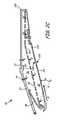
- FIG. 3Ais a cross-sectional view of a gas path wall for the cooling assembly, taken in a longitudinal direction.
- FIG. 3Bis a cross-sectional view of the gas path wall, showing the outlet portion of the cooling hole with a ridge configuration.
- FIG. 3Cis a cross-sectional view of the gas path wall, taken in a transverse direction.
- FIG. 3Dis a perspective view one embodiment of a cooling hole.
- FIG. 4Ais a schematic view of the gas path wall, illustrating a lobed cooling hole geometry in the outlet region.
- FIG. 4Bis a schematic view of the gas path wall, illustrating a cusped cooling hole geometry in the inlet region.
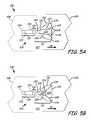
- FIG. 5Ais a schematic view of the gas path wall, illustrating a three-lobe cooling hole geometry in the outlet region.
- FIG. 5Bis a schematic view of the gas path wall, illustrating a buried ridge cooling hole geometry in the outlet region.
- FIG. 6is a block diagram of a method for forming a cooling hole in a gas turbine engine component.
- FIG. 1is a cross-sectional view of gas turbine engine 10 .
- Gas turbine engine (or turbine engine) 10includes a power core with compressor section 12 , combustor 14 and turbine section 16 arranged in flow series between upstream inlet 18 and downstream exhaust 20 .
- Compressor section 12 and turbine section 16are arranged into a number of alternating stages of rotor airfoils (or blades) 22 and stator airfoils (or vanes) 24 .
- propulsion fan 26is positioned in bypass duct 28 , which is coaxially oriented about the engine core along centerline (or turbine axis) C L .
- An open-rotor propulsion stage 26may also provided, with turbine engine 10 operating as a turboprop or unducted turbofan engine.
- fan rotor 26 and bypass duct 28may be absent, with turbine engine 10 configured as a turbojet or turboshaft engine, or an industrial gas turbine.
- components of gas turbine engine 10are provided with an improved cooling configuration, as described below.
- Suitable components for the cooling configurationinclude rotor airfoils 22 , stator airfoils 24 and other gas turbine engine components exposed to hot gas flow, including, but not limited to, platforms, shrouds, casings and other endwall surfaces in hot sections of compressor 12 and turbine 16 , and liners, nozzles, afterburners, augmentors and other gas wall components in combustor 14 and exhaust section 20 .
- compressor section 12includes low pressure compressor (LPC) 30 and high pressure compressor (HPC) 32
- turbine section 16includes high pressure turbine (HPT) 34 and low pressure turbine (LPT) 36
- Low pressure compressor 30is rotationally coupled to low pressure turbine 36 via low pressure (LP) shaft 38 , forming the LP spool or low spool.
- High pressure compressor 32is rotationally coupled to high pressure turbine 34 via high pressure (HP) shaft 40 , forming the HP spool or high spool.
- Flow F at inlet 18divides into primary (core) flow F P and secondary (bypass) flow F S downstream of fan rotor 26 .
- Fan rotor 26accelerates secondary flow F S through bypass duct 28 , with fan exit guide vanes (FEGVs) 42 to reduce swirl and improve thrust performance.
- FEGVsfan exit guide vanes
- structural guide vanes (SGVs) 42are used, providing combined flow turning and load bearing capabilities.
- Primary flow F Pis compressed in low pressure compressor 30 and high pressure compressor 32 , then mixed with fuel in combustor 14 and ignited to generate hot combustion gas.
- the combustion gasexpands to provide rotational energy in high pressure turbine 34 and low pressure turbine 36 , driving high pressure compressor 32 and low pressure compressor 30 , respectively.
- Expanded combustion gasesexit through exhaust section (or exhaust nozzle) 20 , which can be shaped or actuated to regulate the exhaust flow and improve thrust performance.
- Low pressure shaft 38 and high pressure shaft 40are mounted coaxially about centerline C L , and rotate at different speeds.
- Fan rotor (or other propulsion stage) 26is rotationally coupled to low pressure shaft 38 .
- fan drive gear system 44is provided for additional fan speed control, improving thrust performance and efficiency with reduced noise output.
- Fan rotor 26may also function as a first-stage compressor for gas turbine engine 10 , and LPC 30 may be configured as an intermediate compressor or booster.
- propulsion stage 26has an open rotor design, or is absent, as described above.
- Gas turbine engine 10thus encompasses a wide range of different shaft, spool and turbine engine configurations, including one, two and three-spool turboprop and (high or low bypass) turbofan engines, turboshaft engines, turbojet engines, and multi-spool industrial gas turbines.
- turbine efficiency and performancedepend on the overall pressure ratio, defined by the total pressure at inlet 18 as compared to the exit pressure of compressor section 12 , for example at the outlet of high pressure compressor 32 , entering combustor 14 .
- Higher pressure ratiosalso result in greater gas path temperatures, increasing the cooling loads on rotor airfoils 22 , stator airfoils 24 and other components of gas turbine engine 10 .
- Suitable componentsinclude, but are not limited to, cooled gas turbine engine components in compressor sections 30 and 32 , combustor 14 , turbine sections 34 and 36 , and exhaust section 20 of gas turbine engine 10 .
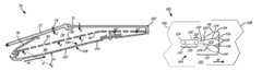
- FIG. 2Ais a perspective view of rotor airfoil (or blade) 22 for gas turbine engine 10 , as shown in FIG. 1 , or for another turbomachine.
- Rotor airfoil 22extends axially from leading edge 51 to trailing edge 52 , defining pressure surface 53 (front) and suction surface 54 (back) therebetween.
- Pressure and suction surfaces 53 and 54form the major opposing surfaces or walls of airfoil 22 , extending axially between leading edge 51 and trailing edge 52 , and radially from root section 55 , adjacent inner diameter (ID) platform 56 , to tip section 57 , opposite ID platform 56 .
- tip section 57is shrouded.
- Cooling holes or outlets 60are provided on one or more surfaces of airfoil 22 , for example along leading edge 51 , trailing edge 52 , pressure (or concave) surface 53 , or suction (or convex) surface 54 , or a combination thereof. Cooling holes or passages 60 may also be provided on the endwall surfaces of airfoil 22 , for example along ID platform 56 , or on a shroud or engine casing adjacent tip section 57 .
- FIG. 2Aalso shows impingement baffle 80 (also called float wall or splash plate) in cutaway view, with impingement holes 82 , as described below with respect to FIG. 2C , for impingement cooling of the inner surface of the hot gas wall of turbine engine component 22 .
- impingement baffle 80also called float wall or splash plate
- impingement holes 82as described below with respect to FIG. 2C , for impingement cooling of the inner surface of the hot gas wall of turbine engine component 22 .
- the inset imageis not to scale.
- film cooling holes 60are formed as cooling holes 104 in the hot gas path wall formed by any one of leading edge 51 , trailing edge 52 , pressure surface 53 , suction surface 54 or platform surface 56 .
- Impingement baffle 80can also be utilized with other inner and outer hot gas path walls 102 and surfaces 106 and 108 of other turbine components, including, but not limited to, combustors, turbine exhaust assemblies, nozzle components, turbine blades, blade outer air seals, and stator airfoil 24 of FIG. 2B .
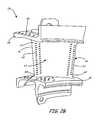
- FIG. 2Bis a perspective view of stator airfoil 24 for gas turbine engine 10 , as shown in FIG. 1 , or for another turbomachine.
- Stator airfoil 24extends axially from leading edge 61 to trailing edge 62 , defining pressure surface 63 (front) and suction surface 64 (back) therebetween.
- Pressure and suction surfaces 63 and 64extend from inner (or root) section 65 , adjacent ID platform 66 , to outer (or tip) section 67 , adjacent outer diameter (OD) platform 68 .
- Cooling holes or outlets 60are provided along one or more surfaces of airfoil 24 , for example leading or trailing edge 61 or 62 , pressure (concave) or suction (convex) surface 63 or 64 , or a combination thereof. Cooling holes or passages 60 may also be provided on the endwall surfaces of airfoil 24 , for example along ID platform 66 and OD platform 68 .
- Rotor airfoils 22 ( FIG. 2A ) and stator airfoils 24 ( FIG. 2B )are formed of high strength, heat resistant materials such as high temperature alloys and superalloys, and are provided with thermal and erosion-resistant coatings.
- Airfoils 22 and 24are also provided with internal cooling passages and cooling holes 60 to reduce thermal fatigue and wear, and to prevent melting when exposed to hot gas flow in the higher temperature regions of a gas turbine engine or other turbomachine.
- Cooling holes 60deliver cooling fluid (e.g., steam or air from a compressor) through the outer walls and platform structures of airfoils 22 and 24 , creating a thin layer (or film) of cooling fluid to protect the outer (gas path) surfaces from high temperature flow.
- cooling fluide.g., steam or air from a compressor
- Cooling holes 60are thus provided with improved metering and inlet geometry to reduce jets and blow off, and improved diffusion and exit geometry to reduce flow separation and corner effects. Cooling holes 60 reduce flow requirements and improve the spread of cooling fluid across the hot surfaces of airfoils 22 and 24 , and other gas turbine engine components, so that less flow is needed for cooling and efficiency is maintained or increased.
- FIG. 2Cis a cross-sectional view of impingement and film cooling assembly 70 .
- Assembly 70includes outer case 72 with cooling fluid apertures 74 for directing cooling fluid flow C into cooling fluid plenum 76 , with seal 78 and float impingement baffle 80 having impingement holes 82 for impingement cooling of turbine component 100 along gas gas path wall 102 .
- gas path wall 102extends along impingement baffle 80 , across impingement plenum 84 .
- First surface 106 of gas path wall 102is exposed to impingement flow of cooling fluid C from cooling fluid plenum 76 , through impingement holes 82 in impingement baffle 80 .
- Second surface 108extends opposite first surface 106 , and is exposed to hot gas flow H, for example combustion gas or exhaust gas.
- Cooling holes 104extend from impingement plenum 84 at first surface 106 through gas path wall 102 to second surface 108 .
- Cooling fluid Cis supplied to cooling plenum 76 via cooling holes 74 in an outer turbine case or other plenum boundary 72 . Cooling fluid C from cooling plenum 76 is supplied to impingement plenum 84 via impingement holes 82 in impingement baffle 80 , where impingement holes 82 are sized to produce jets of cooling fluid flow C impinging onto first surface 106 of gas path wall 102 .
- impingement holes 82are pointed at first surface 106 of gas path wall 102 between cooling holes 104 .
- the spacing between baffle wall (impingement plenum) 84 and gas path wall 102may be equal to or less than about three times the inlet diameter of cooling holes 104 .
- Cooling holes 104extend through gas path wall 102 from first (relatively cool) surface 106 to second (relatively hot) surface 108 .
- Axis Ais an approximate longitudinal axis of flow of cooling holes 104 .
- Axis Ais inclined in a downstream sense at angle ⁇ with respect to the direction of hot gas flow H, in order to encourage attached flow along second surface 108 of gas path wall 102 .
- cooling holes 104also have a circumferential component, in order to encourage tangential film flow.
- cooling assembly 70may be configured for use with a turbine exhaust assembly or similar gas turbine engine component 100 in low pressure turbine 36 or exhaust section 20 of gas turbine engine 10 , as shown in FIG. 1 , or with a combustor liner assembly or similar gas turbine engine component 100 for combustor 14 .
- cooling assembly 70may be configured for use with a cooled turbine liner or casing component 100 in high pressure turbine 34 or low pressure turbine 36 , a hot section compressor liner or casing component 100 for high pressure compressor 32 , or an exhaust nozzle liner or augmentor component 100 for exhaust section 20 .
- cooling assembly 70is configured for use with rotor airfoil 22 , stator airfoil 24 or other airfoil component 100 , with cooling hole 104 forming cooling hole 60 in a pressure surface, suction surface or platform surface, as shown in FIGS. 2A and 2B .
- Impingement baffle 80extends within airfoil component 100 , adjacent first surface 106 of gas path wall 102 , where first surface 106 is an inner surface of the airfoil, and second surface 108 is an outer surface exposed to hot working fluid flow.
- cooling assembly 70are typically manufactured from durable heat-resistant materials such as high-temperature metal alloys or superalloys, in order to protect from hot gas flow H.
- thermal barrier coatings and other protective coatingsmay be used, as described above for airfoils 22 and 24 .
- cooling holes 104are configured with improved metering and diffusive flow geometries, as described below.
- FIG. 3Ais a cross-sectional view of gas turbine engine component (turbine or turbomachinery component) 100 with gas path wall 102 , taken in a longitudinal direction and that carries a cool first surface 106 and an opposite, hot second surface 108 .
- Cooling hole 104extends through gas path wall 102 from first surface 106 to second surface 108 .
- FIG. 3Aalso shows impingement baffle 80 with impingement holes 82 , forming an impingement and film cooling assembly 70 , as described above (see also FIGS. 3B , 3 C, below).
- Cooling fluid Cflows through impingement hole 82 to first surface 106 to provide impingement cooling on first surface 106 . Cooling fluid C then flows along first surface 106 to and through cooling hole 104 .
- first surface 106includes bump 107 substantially aligned with impingement hole 82 such that cooling fluid c flowing through impingement hole 82 flows over bump 107 .
- Bump 107is a structure with a convex surface extending from first surface 106 toward impingement baffle 80 . Bump 107 can increase heat transfer surface area of a portion of first surface 106 exposed to impingement cooling from impingement hole 82 as cooling fluid C flows over bump 107 .
- Bump 107can have an aerodynamic shape that has a relatively steep slope in a longitudinally upstream direction and a relatively gradual slope in a longitudinally downstream direction toward inlet 114 of cooling hole 104 .
- bump 107can have a shape other than as illustrated, such as a hemisphere. In further alternative embodiments, bump 107 can be omitted.
- Gas path wall 102 of component 100is exposed to cooling fluid C on first surface 106 , with longitudinal hot gas flow H along second surface 108 .
- first surface 106is an inner surface and second surface 108 is an outer surface.
- first surface 106is an outer surface
- second surface 108is an inner surface. More generally, the terms inner and outer are merely representative, and may be interchanged.
- Metering section 110 of cooling hole 104extends from inlet 114 at first surface 106 of gas path wall 102 to transition 118 .
- Diffusing section 112extends from transition 118 to outlet 116 at second surface 108 .
- Transition 118is defined between metering section 110 and diffusing section 112 , including any region of overlap.
- Cooling hole 104delivers cooling fluid C from first surface 106 of wall 102 to second surface 108 , for example to provide diffusive flow and film cooling. Cooling hole 104 is inclined along axis A in a downstream direction with respect to hot gas flow H, in order to improve cooling fluid coverage over second surface 108 , with less separation and reduced flow mixing.
- Impingement baffle 80is spaced from first surface 106 of gas path wall 102 by distance D 1 .
- Impingement hole 82has a distance D 2 from its upstream surface 121 to its downstream surface 123 .
- Cooling hole 104has a distance D 4 from its upstream surface 120 to its downstream surface 122 at inlet 114 .
- Distance D 3is a distance in a longitudinal direction from downstream surface 123 of impingement hole 82 to upstream surface 120 of cooling hole 104 .
- distance D 1can be less than or equal to four times distance D 2 .
- Distance D 3can be equal to between one times distance D 2 and ten times distance D 2 .
- distance D 2can be equal to, less than, or greater than distance D 4 .
- a flow area of impingement hole 82can be equal to, less than, or greater than a flow area of inlet 114 .
- impingement hole 82need not be cylindrical.
- impingement hole 82could be an elongated slot. In that embodiment, there can be a substantially greater number of cooling holes 104 than impingement holes 82 .
- impingement holes 82could be micro-holes through impingement baffle 80 , with a quantity that is substantially greater than that of cooling hole 104 .
- metering section 110 of cooling hole 104has substantially constant or decreasing cross-sectional area between inlet 114 and transition 118 , with upstream and downstream surfaces 120 and 122 converging or extending generally parallel to one another along axis A. This maintains or decreases the longitudinal dimension (along hot gas flow H) of cooling hole 104 from inlet 114 through metering section 110 to transition 118 , in order to regulate the cooling fluid flow from inlet 114 .
- Diffusing section 112 of cooling hole 104diverges between transition 118 and outlet 116 . That is, upstream and downstream surfaces 120 and 122 diverge from one another and away from axis A in the longitudinal direction, in the region from transition 118 through diffusing section 112 to outlet 116 . This increases the cross sectional flow area of diffusing section 112 , in order to provide diffusive flow between transition 118 and outlet 116 .
- Transition 118is defined in the region between metering section 110 and diffusing section 112 , where cooling hole 104 becomes divergent (increasing flow area), and where the cooling fluid flow becomes diffusive. Transition 118 may be relatively abrupt, or may encompass an extended region or section of cooling hole 104 , for example in a flow transition region between metering section 110 and diffusing section 112 , or over a region of overlap between metering section 110 and diffusing section 112 .
- Longitudinal ridge 124projects out (toward axis A) from downstream surface 122 of cooling hole 104 , discouraging vortex flow and dividing cooling hole 104 into lobes along diffusing section 112 , in order to reduce swirl and mixing at outlet 116 .
- longitudinal ridge 124extends along transition region 128 to trailing edge 126 of outlet 116 , in order to discourage detachment and improve flow uniformity along second surface 108 of gas path wall 102 , downstream of cooling hole 104 at outlet 116 (see also, e.g., FIGS. 4A , 4 B, 5 A, 5 B).
- transition region 128can be flat or planar.
- transition region 128can be non-flat and non-planar, such as curved (e.g. convex) longitudinally and/or laterally.
- FIG. 3Bis a cross-sectional view of gas turbine engine component 100 with gas path wall 102 , showing cooling hole 104 with longitudinal ridge 124 .
- longitudinal ridge 124extends through transition 118 and along metering section 110 to cusp 125 on inlet 114 .
- Cusp 125co-extends with ridge 124 , from inlet 114 and along metering section 110 to transition 118 . Like longitudinal ridge 124 , cusp 125 extends outward (toward axis A) from downstream surface 122 of cooling hole 104 , discouraging lateral flow components to reduce swirl in metering section 110 .
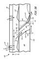
- FIG. 3Cis a transverse cross sectional view of gas path wall 102 , taken along axis A and looking in a downstream direction, in a plane perpendicular or transverse to the longitudinal cross sections of FIGS. 3A and 3B .
- hot gas flow His directed into the page, and lateral side surfaces 130 and 132 are separated in the transverse direction across axis A, perpendicular to hot gas flow H.
- first and second side surfaces 130 and 132 of cooling hole 104are substantially parallel along axis A in metering section 110 between inlet 114 and transition 118 .
- side surfaces 130 and 132converge toward one another through metering section 110 , so that the flow area of cooling hole 104 decreases or remains constant (i.e., does not increase) between inlet 114 and transition 118 .
- metering section 110restricts flow from inlet 114 through transition 118 , reducing the flow rate and improving efficiency by providing only the desired level of cooling fluid flow to diffusing section 112 .
- This metering designprovides more efficient cooling flow from outlet 116 , with greater coverage along second surface 108 of gas path wall 102 .
- diffusing section 112In diffusing section 112 , side surfaces 130 and 132 diverge laterally from one another (and from axis A) between transition 118 and outlet 116 . Thus, diffusing section 112 is divergent both in the longitudinal direction as shown in FIGS. 3A and 3B , and in the transverse direction as shown in FIG. 3C . This configuration improves diffusive flow between transition 118 and outlet 116 , discouraging flow separation at trailing edge 126 and improving cooling performance along second surface 108 of gas path wall 102 .
- cooling hole 104The cross-sectional geometry of cooling hole 104 varies, as described above, and as shown in the figures. Moreover, the design of cooling hole 104 is not limited to these particular examples, but also encompasses different combinations and variations of the features that are described, including different metering sections 110 with parallel or converging surfaces 120 , 122 , 130 and 132 , different diffusing sections 112 with diverging surfaces 120 , 122 , 130 and 132 , and different transitions 118 as defined between metering section 110 and diffusing section 112 .
- FIG. 3Dis a perspective view one embodiment of cooling hole 104 , showing only the surfaces that define cooling hole 104 (with gas path wall 102 omitted for clarity).
- FIG. 3Dillustrates surfaces 120 , 122 , 130 and 132 being substantially parallel at metering section 110 , and surfaces 120 , 122 , 130 and 132 substantially diverging at diffusing section 112 .
- Longitudinal ridge 124extends along cooling hole 104 between transition 118 and outlet 116 , dividing cooling hole 104 into two lobes 134 along diffusing section 112 .
- FIG. 4Ais a schematic view of gas path wall 102 , illustrating a lobed configuration for cooling hole 104 in diffusing section 112 .
- one longitudinal ridge 124extends along cooling hole 104 between transition 118 and outlet 116 , dividing cooling hole 104 into two lobes 134 along diffusing section 112 .
- Lobes 134are surfaces of wall 102 which define distinct channel-like portions of the void of cooling hole 104 .
- Diffusing section 112 of cooling hole 104diverges (widens) in a lateral direction and/or in a longitudinal direction, as described above. This configuration promotes diffusive flow through cooling hole 104 , from transition 118 through diffusing section 112 to outlet 116 , for more uniform coverage with less detachment along second surface 108 of gas path wall 102 .
- outlet 116is also selected to improve cooling performance.
- outlet 116is formed as a delta, with arcuate upstream surface 120 intersecting second surface 108 of gas path wall 102 and extending to substantially linear or straight trailing edge 126 , transverse or perpendicular to hot gas flow H in order to reduce separation along second surface 108 of gas path wall 102 .
- Transition region 128extends laterally between arcuate extensions 136 from longitudinal ridges 124 , where arcuate extensions 136 are defined along boundaries with adjacent lobes 134 .
- longitudinal ridge 124splits or bifurcates into two arcuate extensions 136 , which extend longitudinally and transversely along diffusing section 112 to trailing edge 126 of outlet 116 .
- cooling hole 104thus has a single transition region 128 , extending along substantially the entire length of trailing edge 126 of outlet 116 .
- FIG. 4Bis a schematic view of gas path wall 102 , illustrating a cusped configuration for cooling hole 104 in metering section 110 .
- longitudinal ridge 124extends through transition 118 and along metering section 110 to cusp 125 on inlet 114 .
- Outlet 116has a general delta convex configuration, intersecting second surface 108 of gas path wall 102 at arcuate upstream surface 120 , and extending downstream to convex trailing edge 126 .
- the size, length and other geometric properties of cusp 125are selected to discourage swirl (vortex) flow in cooling hole 104 or near second surface 108 , for example by introducing a canceling vortex pair into the cooling fluid to weaken kidney-shaped vortices formed at outlet 116 .
- Lobes 134can have arcuate or curved surfaces along downstream surface 122 of diffusing section 112 , forming longitudinal ridge 124 as a cusped ridge or rib structure similar to cusp 125 .
- longitudinal ridge 124 and cusp 125may be congruently formed as extensions of one another, with ridge 124 and cusp 125 having similar geometry along downstream surface 122 of cooling hole 104 .
- longitudinal ridge 124may extend independently of cusp 125 , for example from an oval or circular transition 118 as shown in FIG. 4A .
- longitudinal ridge 124 and cusp 125also vary.
- one or both of longitudinal ridge 124 and cusp 125may be formed as long, narrow processes extending along the wall of cooling hole 104 , either where the sloping surfaces of adjacent lobes 134 meet, or as a narrow raised band or rib structure between adjacent lobes 134 .
- Longitudinal ridge 124 and cusp 125may also form either substantially pointed or more rounded features along adjacent lobes 134 , or where the direction of curvature reverses along surfaces 120 , 122 , 130 or 132 of cooling hole 104 .
- Longitudinal ridge 124 and cusp 125may also be formed as arched or cone-shape features between adjacent lobes 134 .
- FIG. 5Ais a schematic view of gas path wall 102 , illustrating a three lobe configuration for cooling hole 104 in diffusing section 112 .
- two longitudinal ridges 124extend from transition 118 toward outlet 116 , dividing cooling hole 104 into three lobes 134 along diffusing section 112 .
- diffusing section 112can include more than three lobes, such as four lobes, five lobes, or six lobes.
- Transition regions 128extend from longitudinal ridges 124 to trailing edge 126 of outlet 116 , between adjacent lobes 134 .
- the mutual boundaries of transition regions 128 and adjacent lobes 134are defined along arcuate extensions 136 , as described above.
- Transition regions 128extend across substantially all of trailing edge 126 , eliminating cusps and other irregularities to provide more uniform flow coverage for better cooling performance along second surface 108 of gas path wall 102 , downstream of outlet 116 . Transition regions 128 can also eliminate sharp corners and reduce thermal mechanical fatigue.
- FIG. 5Bis a schematic view of gas turbine engine component 100 with gas path wall 102 , illustrating a “flushed” divider or ridge configuration for diffusing section 112 of cooling hole 104 .
- longitudinal ridges 124extend from transition 118 toward outlet 116 , dividing diffusing section 112 into two lobes 134 as described above. In this configuration, however, longitudinal ridge 124 is smoothed out and terminates at transition region 128 , as bounded between intersections 142 along adjacent (outer) lobes 134 .
- intersections 142do not extend above downstream surface 122 toward axis A of cooling hole 104 . Instead, transition region 128 is defined along downstream surface 122 , and adjacent lobes 134 curve up from intersections 142 toward second (upper) surface 108 of gas path wall 102 . Transition region 128 extends across substantially all of trailing edge 126 , as descried above, eliminating cusps and other irregularities for more uniform flow.
- cooling hole 104thus varies, as described above, and as shown in the figures.
- the design of inlet 114 and outlet 116may also vary, including various circular, oblate, oval, trapezoidal, triangular, cusped and delta shaped profiles with arcuate or piecewise linear upstream surfaces 120 and straight or convex trailing edges 126 .
- cooling hole 104is not limited to these particular examples, moreover, but also encompasses different combinations of the various features that are shown, including metering section 110 with a variety of different cusps 125 ; transitions 118 with different circular, elliptical, oblong and cusped cross sections; and diffusing sections 112 with one, two or three lobes 134 , in combination with different transition regions 128 bordered by various arcuate extensions 136 and intersections 142 .
- FIG. 6is a block diagram illustrating method 200 for forming an impingement and film (float wall) cooling assembly for a gas turbine engine component.
- method 200may be used to form cooling assembly 70 with impingement baffle 80 and gas path wall 102 for a combustor liner, turbine exhaust assembly, exhaust nozzle, augmentor or other gas turbine engine component 100 , as described above.
- method 200may be used to form cooling assembly 70 with cooling holes 104 configured as cooling holes 60 in rotor airfoil 22 or stator airfoil 24 , as shown in FIGS. 2A and 2B , or in another airfoil component 100 .
- Method 200includes forming a gas path wall (step 202 ) for the component, forming an impingement baffle (step 204 ) spaced from the gas path wall, and forming a cooling hole (step 206 ) in the gas path wall.
- forming a cooling hole (step 206 )may include forming an inlet in a first (e.g., cool) surface of the gas path wall (step 208 ), forming an outlet in a second (e.g., hot) surface of the gas path wall (step 210 ), and forming a cooling hole (step 212 ) between the inlet and the outlet.
- the cooling hole (step 212 )extends from the first surface of the gas path wall to the second surface.
- Forming the cooling hole (step 212 )includes forming a metering section extending from the inlet along the cooling hole to a transition, and forming a diffusing section extending from the transition along the cooling hole to the outlet.
- the cross sectional flow area of the metering sectionis constant or deceasing from the inlet to the transition, in order to regulate the flow of cooling fluid through the cooling hole.
- the cross sectional flow area of the diffusing sectionincreases from the transition to the outlet, in order to provide diffusive flow for improved cooling fluid coverage.
- One or more longitudinal ridgesmay be formed along the cooling hole to divide the diffusing section of the cooling hole into lobes.
- the longitudinal ridgesare formed as rib, ridge or cusps, as described above, for example along a downstream wall of the cooling hole.
- the longitudinal ridgesextend out from the wall toward the axis of the cooling hole, in order to discourage swirl and reduce losses at the outlet.
- a longitudinal ridgeextends from the transition and along the metering section of the cooling hole to a cusp on the inlet. In other designs, a ridge extends along the metering section from a ridge terminus located between the inlet and the outlet, for example at the transition. In further designs, a transition region (step 216 ) extends from a longitudinal ridge to the trailing edge of the outlet.
- the gas turbine engine components, gas path walls and cooling holes described hereincan thus be manufactured using one or more of a variety of different processes. These techniques provide each cooling hole with its own particular configuration and features, including, but not limited to, inlet, metering, transition, diffusion, outlet, upstream surface, downstream surface, lateral surface, longitudinal, lobe and downstream edge features, as described above. In some cases, multiple techniques can be combined to improve overall cooling performance or reproducibility, or to reduce manufacturing costs.
- Suitable manufacturing techniques for forming the cooling configurations described hereinclude, but are not limited to, electrical discharge machining (EDM), laser drilling, laser machining, electrical chemical machining (ECM), water jet machining, casting, conventional machining and combinations thereof.
- Electrical discharge machiningincludes both machining using a shaped electrode as well as multiple pass methods using a hollow spindle or similar electrode component.
- Laser machining methodsinclude, but are not limited to, material removal by ablation, trepanning and percussion laser machining.
- Conventional machining methodsinclude, but are not limited to, milling, drilling and grinding.
- the gas path walls and outer surfaces of some gas turbine engine componentsinclude one or more coatings, such as bond coats, thermal barrier coatings, abrasive coatings, abradable coatings and erosion or erosion-resistant coatings.
- coatingssuch as bond coats, thermal barrier coatings, abrasive coatings, abradable coatings and erosion or erosion-resistant coatings.
- the inlet, metering section, transition, diffusing section and outlet cooling featuresmay be formed prior to a coating application, after a first coating (e.g., a bond coat) is applied, or after a second or third (e.g., interlayer) coating process, or a final coating (e.g., environmental or thermal barrier) process.
- the diffusing section and outlet featuresmay be located within a wall or substrate, within a thermal barrier coating or other coating layer applied to a wall or substrate, or combinations thereof.
- the cooling geometry and other featuresmay remain as described above, regardless of position relative to the wall and coating materials or airfoil materials.
- cooling featuresmay affect selection of manufacturing techniques, including techniques used in forming the inlet, metering section, transition, outlet, diffusing section and other cooling features.
- manufacturing techniquesincluding techniques used in forming the inlet, metering section, transition, outlet, diffusing section and other cooling features.
- thermal barrier coat or other coatingis applied to the outer surface of a gas path wall before the cooling hole is produced.
- laser ablation or laser drillingmay be used.
- either laser drilling or water jet machiningmay be used on a surface without a thermal barrier coat.
- different machining methodsmay be more or less suitable for forming different features of the cooling hole, for example, different EDM, laser machining and other machining techniques may be used for forming the outlet and diffusion features, and for forming the transition, metering and inlet features.
- a gas turbine engine componentcan include a gas path wall having a first and second opposing surfaces and a baffle positioned along the gas path wall.
- the bafflecan have impingement holes for directing cooling fluid onto the first surface of the gas path wall.
- a cooling holecan be formed in the gas path wall and extends from a metering section having an inlet in the first surface through a transition to a diffusing section having an outlet in the second surface.
- a longitudinal ridgecan extend along the cooling hole between the transition and the outlet. The longitudinal ridge can divide the diffusing section of the cooling hole into first and second lobes.
- the component of the preceding paragraphcan optionally include, additionally and/or alternatively any, one or more of the following features, configurations and/or additional components:
- the longitudinal ridgecan be a first longitudinal ridge
- the componentcan further include a second longitudinal ridge and a third lobe
- the first and second longitudinal ridgescan divide the cooling hole into the first, second, and third lobes
- the longitudinal ridgecan extend through the transition and along the metering section of the cooling hole to a cusp on the inlet;
- the outletcan have an arcuate upstream wall extending downstream to a substantially straight trailing edge
- the cooling holecan be one of a plurality of cooling holes and each of the impingement holes can be paired with and positioned upstream of one of the cooling holes;
- the impingement holescan be are substantially cylindrical
- bumpscan extend from the first surface toward the baffle and be substantially aligned with the impingement holes
- the bumpscan have a convex surface with a relatively steep slope in a longitudinally upstream direction and a relatively gradual slope in a longitudinally downstream direction;
- a transition regioncan extend from the longitudinal ridge to a trailing edge of the outlet, and the longitudinal ridge can terminate at the transition region;
- a combustor assemblycan include the component.
- a liner assembly for a gas turbine enginecan include an impingement baffle having impingement holes and a liner wall having a first surface extending along the impingement baffle and a second surface extending opposite the first surface.
- a cooling holecan be formed in the liner wall.
- the cooling holecan include a metering section having an inlet in the first surface, a diffusing section having an outlet in the second surface, and a transition between the metering section and the diffusing section.
- a longitudinal ridgecan extend between the transition and the outlet. The longitudinal ridge can divide the diffusing section of the cooling hole into first and second lobes.
- the liner assembly of the preceding paragraphcan optionally include, additionally and/or alternatively any, one or more of the following features, configurations and/or additional components:
- cross sectional area of the cooling holecan not increase from the inlet through the metering section to the transition;
- cross sectional area of the cooling holecan increase from the transition through the diffusing section to the outlet.
- the longitudinal ridgecan be a first longitudinal ridge
- the cooling holecan include a second longitudinal ridge and a third lobe
- the first and second longitudinal ridgescan divide the cooling hole into the first, second, and third lobes
- the longitudinal ridgecan extend through the transition and along the metering section of the cooling hole to a cusp on the inlet;
- the cooling holecan be one of a plurality of cooling holes and each of the impingement holes can be paired with and positioned upstream of one of the cooling holes;
- the impingement holescan be substantially elongated slots
- bumpscan extend from the first surface toward the impingement baffle and be substantially aligned with the impingement holes
- the bumpscan have a convex surface with a relatively steep slope in a longitudinally upstream direction and a relatively gradual slope in a longitudinally downstream direction;
- a gas turbine engine componentcan include the liner assembly.
Landscapes
- Engineering & Computer Science (AREA)
- Mechanical Engineering (AREA)
- General Engineering & Computer Science (AREA)
- Chemical & Material Sciences (AREA)
- Combustion & Propulsion (AREA)
- Physics & Mathematics (AREA)
- Fluid Mechanics (AREA)
- Turbine Rotor Nozzle Sealing (AREA)
Abstract
Description
Claims (20)
Priority Applications (3)
| Application Number | Priority Date | Filing Date | Title |
|---|---|---|---|
| US13/544,257US8683814B2 (en) | 2012-02-15 | 2012-07-09 | Gas turbine engine component with impingement and lobed cooling hole |
| PCT/US2013/026040WO2013123120A1 (en) | 2012-02-15 | 2013-02-14 | Gas turbine engine component with impingement and lobed cooling hole |
| EP13749061.1AEP2815078B1 (en) | 2012-02-15 | 2013-02-14 | Gas turbine engine component and corresponding combustor assembly |
Applications Claiming Priority (2)
| Application Number | Priority Date | Filing Date | Title |
|---|---|---|---|
| US201261599315P | 2012-02-15 | 2012-02-15 | |
| US13/544,257US8683814B2 (en) | 2012-02-15 | 2012-07-09 | Gas turbine engine component with impingement and lobed cooling hole |
Publications (2)
| Publication Number | Publication Date |
|---|---|
| US20130205794A1 US20130205794A1 (en) | 2013-08-15 |
| US8683814B2true US8683814B2 (en) | 2014-04-01 |
Family
ID=48944503
Family Applications (1)
| Application Number | Title | Priority Date | Filing Date |
|---|---|---|---|
| US13/544,257ActiveUS8683814B2 (en) | 2012-02-15 | 2012-07-09 | Gas turbine engine component with impingement and lobed cooling hole |
Country Status (3)
| Country | Link |
|---|---|
| US (1) | US8683814B2 (en) |
| EP (1) | EP2815078B1 (en) |
| WO (1) | WO2013123120A1 (en) |
Cited By (12)
| Publication number | Priority date | Publication date | Assignee | Title |
|---|---|---|---|---|
| US20160090843A1 (en)* | 2014-09-30 | 2016-03-31 | General Electric Company | Turbine components with stepped apertures |
| US20160273771A1 (en)* | 2013-11-25 | 2016-09-22 | United Technologies Corporation | Film cooled multi-walled structure with one or more indentations |
| DE102015210385A1 (en)* | 2015-06-05 | 2016-12-08 | Rolls-Royce Deutschland Ltd & Co Kg | Device for cooling a wall of a component of a gas turbine |
| US20170067699A1 (en)* | 2015-09-08 | 2017-03-09 | General Electric Company | Article, component, and method of forming an article |
| US20190072033A1 (en)* | 2017-09-06 | 2019-03-07 | United Technologies Corporation | Dirt collector system |
| US10400607B2 (en) | 2014-12-30 | 2019-09-03 | United Technologies Corporation | Large-footprint turbine cooling hole |
| US10443396B2 (en) | 2016-06-13 | 2019-10-15 | General Electric Company | Turbine component cooling holes |
| US10619488B2 (en)* | 2014-10-31 | 2020-04-14 | General Electric Company | Engine component assembly |
| US10731857B2 (en) | 2014-09-09 | 2020-08-04 | Raytheon Technologies Corporation | Film cooling circuit for a combustor liner |
| US10788210B2 (en) | 2014-09-09 | 2020-09-29 | Raytheon Technologies Corporation | Single-walled combustor for a gas turbine engine and method of manufacture |
| US10951095B2 (en) | 2018-08-01 | 2021-03-16 | General Electric Company | Electric machine arc path protection |
| US11371386B2 (en) | 2012-02-15 | 2022-06-28 | Raytheon Technologies Corporation | Manufacturing methods for multi-lobed cooling holes |
Families Citing this family (24)
| Publication number | Priority date | Publication date | Assignee | Title |
|---|---|---|---|---|
| US9175569B2 (en) | 2012-03-30 | 2015-11-03 | General Electric Company | Turbine airfoil trailing edge cooling slots |
| US9145773B2 (en) | 2012-05-09 | 2015-09-29 | General Electric Company | Asymmetrically shaped trailing edge cooling holes |
| EP2861909A2 (en) | 2012-06-13 | 2015-04-22 | General Electric Company | Gas turbine engine wall |
| US20160169004A1 (en)* | 2014-12-15 | 2016-06-16 | United Technologies Corporation | Cooling passages for gas turbine engine component |
| US10590774B2 (en)* | 2015-01-22 | 2020-03-17 | General Electric Company | Turbine bucket for control of wheelspace purge air |
| CA2933884A1 (en)* | 2015-06-30 | 2016-12-30 | Rolls-Royce Corporation | Combustor tile |
| EP3124744A1 (en)* | 2015-07-29 | 2017-02-01 | Siemens Aktiengesellschaft | Vane with impingement cooled platform |
| FR3040439B1 (en)* | 2015-08-31 | 2020-06-05 | Safran Aircraft Engines | DOUBLE-FLOW TURBOREACTOR WITH CONFLUENCE WALL |
| EP3141702A1 (en)* | 2015-09-14 | 2017-03-15 | Siemens Aktiengesellschaft | Gas turbine guide vane segment and method of manufacturing |
| US10495309B2 (en)* | 2016-02-12 | 2019-12-03 | General Electric Company | Surface contouring of a flowpath wall of a gas turbine engine |
| US11021965B2 (en)* | 2016-05-19 | 2021-06-01 | Honeywell International Inc. | Engine components with cooling holes having tailored metering and diffuser portions |
| EP3354849A1 (en) | 2017-01-31 | 2018-08-01 | Siemens Aktiengesellschaft | Wall of a hot gas part and corresponding hot gas part for a gas turbine |
| US10876407B2 (en)* | 2017-02-16 | 2020-12-29 | General Electric Company | Thermal structure for outer diameter mounted turbine blades |
| US10644630B2 (en)* | 2017-11-28 | 2020-05-05 | General Electric Company | Turbomachine with an electric machine assembly and method for operation |
| US10502093B2 (en)* | 2017-12-13 | 2019-12-10 | Pratt & Whitney Canada Corp. | Turbine shroud cooling |
| US10648342B2 (en)* | 2017-12-18 | 2020-05-12 | General Electric Company | Engine component with cooling hole |
| US10837314B2 (en) | 2018-07-06 | 2020-11-17 | Rolls-Royce Corporation | Hot section dual wall component anti-blockage system |
| US11248790B2 (en) | 2019-04-18 | 2022-02-15 | Rolls-Royce Corporation | Impingement cooling dust pocket |
| US11112114B2 (en)* | 2019-07-23 | 2021-09-07 | Raytheon Technologies Corporation | Combustor panels for gas turbine engines |
| US11428171B2 (en) | 2019-12-06 | 2022-08-30 | General Electric Company | Electric machine assistance for multi-spool turbomachine operation and control |
| FR3106157B1 (en)* | 2020-01-10 | 2023-04-28 | Safran Aircraft Engines | TURBOMACHINE COMPONENT FEATURING ENHANCED COOLING HOLES |
| CN111578310A (en)* | 2020-04-30 | 2020-08-25 | 南京理工大学 | A film cooling hole structure for turboshaft engine |
| US11459898B2 (en)* | 2020-07-19 | 2022-10-04 | Raytheon Technologies Corporation | Airfoil cooling holes |
| US11674686B2 (en) | 2021-05-11 | 2023-06-13 | Honeywell International Inc. | Coating occlusion resistant effusion cooling holes for gas turbine engine |
Citations (68)
| Publication number | Priority date | Publication date | Assignee | Title |
|---|---|---|---|---|
| US4153386A (en) | 1974-12-11 | 1979-05-08 | United Technologies Corporation | Air cooled turbine vanes |
| US4197443A (en) | 1977-09-19 | 1980-04-08 | General Electric Company | Method and apparatus for forming diffused cooling holes in an airfoil |
| US4529358A (en) | 1984-02-15 | 1985-07-16 | The United States Of America As Represented By The Administrator Of The National Aeronautics And Space Administration | Vortex generating flow passage design for increased film cooling effectiveness |
| US4622821A (en) | 1985-01-07 | 1986-11-18 | United Technologies Corporation | Combustion liner for a gas turbine engine |
| US4653983A (en) | 1985-12-23 | 1987-03-31 | United Technologies Corporation | Cross-flow film cooling passages |
| US4653279A (en) | 1985-01-07 | 1987-03-31 | United Technologies Corporation | Integral refilmer lip for floatwall panels |
| US4672727A (en) | 1985-12-23 | 1987-06-16 | United Technologies Corporation | Method of fabricating film cooling slot in a hollow airfoil |
| US4684323A (en) | 1985-12-23 | 1987-08-04 | United Technologies Corporation | Film cooling passages with curved corners |
| US4700544A (en) | 1985-01-07 | 1987-10-20 | United Technologies Corporation | Combustors |
| US4738588A (en) | 1985-12-23 | 1988-04-19 | Field Robert E | Film cooling passages with step diffuser |
| US5062768A (en) | 1988-12-23 | 1991-11-05 | Rolls-Royce Plc | Cooled turbomachinery components |
| US5096379A (en) | 1988-10-12 | 1992-03-17 | Rolls-Royce Plc | Film cooled components |
| US5129231A (en) | 1990-03-12 | 1992-07-14 | United Technologies Corporation | Cooled combustor dome heatshield |
| US5252026A (en) | 1993-01-12 | 1993-10-12 | General Electric Company | Gas turbine engine nozzle |
| US5326224A (en) | 1991-03-01 | 1994-07-05 | General Electric Company | Cooling hole arrangements in jet engine components exposed to hot gas flow |
| US5358374A (en) | 1993-07-21 | 1994-10-25 | General Electric Company | Turbine nozzle backflow inhibitor |
| US5382133A (en) | 1993-10-15 | 1995-01-17 | United Technologies Corporation | High coverage shaped diffuser film hole for thin walls |
| US5418345A (en) | 1994-02-28 | 1995-05-23 | United Technologies Corporation | Method for forming shaped passages |
| US5419681A (en) | 1993-01-25 | 1995-05-30 | General Electric Company | Film cooled wall |
| US5609779A (en) | 1996-05-15 | 1997-03-11 | General Electric Company | Laser drilling of non-circular apertures |
| US5651662A (en) | 1992-10-29 | 1997-07-29 | General Electric Company | Film cooled wall |
| US5660525A (en) | 1992-10-29 | 1997-08-26 | General Electric Company | Film cooled slotted wall |
| US5683600A (en) | 1993-03-17 | 1997-11-04 | General Electric Company | Gas turbine engine component with compound cooling holes and method for making the same |
| US5813836A (en) | 1996-12-24 | 1998-09-29 | General Electric Company | Turbine blade |
| US6139258A (en) | 1987-03-30 | 2000-10-31 | United Technologies Corporation | Airfoils with leading edge pockets for reduced heat transfer |
| US6183199B1 (en) | 1998-03-23 | 2001-02-06 | Abb Research Ltd. | Cooling-air bore |
| US6241468B1 (en) | 1998-10-06 | 2001-06-05 | Rolls-Royce Plc | Coolant passages for gas turbine components |
| US6243948B1 (en) | 1999-11-18 | 2001-06-12 | General Electric Company | Modification and repair of film cooling holes in gas turbine engine components |
| US6287075B1 (en) | 1997-10-22 | 2001-09-11 | General Electric Company | Spanwise fan diffusion hole airfoil |
| US6307175B1 (en) | 1998-03-23 | 2001-10-23 | Abb Research Ltd. | Method of producing a noncircular cooling bore |
| US20010036401A1 (en) | 2000-01-22 | 2001-11-01 | Harvey Neil W. | Aerofoil for an axial flow turbomachine |
| US20020159888A1 (en) | 2001-04-27 | 2002-10-31 | Rinck Gerard Anthony | Methods and systems for cooling gas turbine engine airfoils |
| US6494678B1 (en) | 2001-05-31 | 2002-12-17 | General Electric Company | Film cooled blade tip |
| US6547524B2 (en) | 2001-05-21 | 2003-04-15 | United Technologies Corporation | Film cooled article with improved temperature tolerance |
| US6572335B2 (en) | 2000-03-08 | 2003-06-03 | Mitsubishi Heavy Industries, Ltd. | Gas turbine cooled stationary blade |
| EP1326007A2 (en) | 1996-05-28 | 2003-07-09 | Kabushiki Kaisha Toshiba | Cooling of a structure for use as a turbine blade |
| US6744010B1 (en) | 1991-08-22 | 2004-06-01 | United Technologies Corporation | Laser drilled holes for film cooling |
| US20050106020A1 (en) | 2003-11-19 | 2005-05-19 | General Electric Company | Hot gas path component with mesh and turbulated cooling |
| US6944580B1 (en) | 2000-06-30 | 2005-09-13 | United Technologies Corporation | Method and system for designing frames and cases |
| US6973419B1 (en) | 2000-03-02 | 2005-12-06 | United Technologies Corporation | Method and system for designing an impingement film floatwall panel system |
| US6979176B2 (en) | 2003-12-19 | 2005-12-27 | Ishikawajima-Harima Heavy Industries Co., Ltd. | Cooled turbine component and cooled turbine blade |
| EP1609949A1 (en) | 2004-06-23 | 2005-12-28 | General Electric Company | Film cooled wall with chevron-shaped cooling holes |
| US7186085B2 (en) | 2004-11-18 | 2007-03-06 | General Electric Company | Multiform film cooling holes |
| US7273351B2 (en) | 2004-11-06 | 2007-09-25 | Rolls-Royce, Plc | Component having a film cooling arrangement |
| US20080003096A1 (en) | 2006-06-29 | 2008-01-03 | United Technologies Corporation | High coverage cooling hole shape |
| US7374401B2 (en) | 2005-03-01 | 2008-05-20 | General Electric Company | Bell-shaped fan cooling holes for turbine airfoil |
| US20080145208A1 (en) | 2006-12-19 | 2008-06-19 | General Electric Company | Bullnose seal turbine stage |
| US20090013695A1 (en) | 2007-07-10 | 2009-01-15 | United Technologies Corp. | Floatwell Panel Assemblies and Related Systems |
| US20090074575A1 (en) | 2007-01-11 | 2009-03-19 | United Technologies Corporation | Cooling circuit flow path for a turbine section airfoil |
| US7578653B2 (en) | 2006-12-19 | 2009-08-25 | General Electric Company | Ovate band turbine stage |
| US20090304499A1 (en) | 2008-06-06 | 2009-12-10 | United Technologies Corporation | Counter-Vortex film cooling hole design |
| US20100068032A1 (en) | 2008-09-16 | 2010-03-18 | Siemens Energy, Inc. | Turbine Airfoil Cooling System with Diffusion Film Cooling Hole |
| US20100068068A1 (en) | 2008-09-16 | 2010-03-18 | Siemens Energy, Inc. | Turbine Airfoil Cooling System with Diffusion Film Cooling Hole Having Flow Restriction Rib |
| US7726131B2 (en) | 2006-12-19 | 2010-06-01 | Pratt & Whitney Canada Corp. | Floatwall dilution hole cooling |
| US7766609B1 (en) | 2007-05-24 | 2010-08-03 | Florida Turbine Technologies, Inc. | Turbine vane endwall with float wall heat shield |
| US20100282721A1 (en) | 2009-05-05 | 2010-11-11 | General Electric Company | System and method for improved film cooling |
| US7887294B1 (en) | 2006-10-13 | 2011-02-15 | Florida Turbine Technologies, Inc. | Turbine airfoil with continuous curved diffusion film holes |
| US20110097191A1 (en) | 2009-10-28 | 2011-04-28 | General Electric Company | Method and structure for cooling airfoil surfaces using asymmetric chevron film holes |
| US20110185572A1 (en) | 2010-01-29 | 2011-08-04 | General Electric Company | Process and system for forming shaped air holes |
| US7997868B1 (en) | 2008-11-18 | 2011-08-16 | Florida Turbine Technologies, Inc. | Film cooling hole for turbine airfoil |
| US8038399B1 (en) | 2008-11-22 | 2011-10-18 | Florida Turbine Technologies, Inc. | Turbine rim cavity sealing |
| US8057181B1 (en) | 2008-11-07 | 2011-11-15 | Florida Turbine Technologies, Inc. | Multiple expansion film cooling hole for turbine airfoil |
| US20110293423A1 (en) | 2010-05-28 | 2011-12-01 | General Electric Company | Articles which include chevron film cooling holes, and related processes |
| US8079812B2 (en)* | 2005-11-01 | 2011-12-20 | Ihi Corporation | Turbine component |
| US20120051941A1 (en) | 2010-08-31 | 2012-03-01 | General Electric Company | Components with conformal curved film holes and methods of manufacture |
| US20120167389A1 (en) | 2011-01-04 | 2012-07-05 | General Electric Company | Method for providing a film cooled article |
| US8245519B1 (en)* | 2008-11-25 | 2012-08-21 | Florida Turbine Technologies, Inc. | Laser shaped film cooling hole |
| US20130115103A1 (en)* | 2011-11-09 | 2013-05-09 | General Electric Company | Film hole trench |
Family Cites Families (6)
| Publication number | Priority date | Publication date | Assignee | Title |
|---|---|---|---|---|
| DE69309437T2 (en) | 1992-11-24 | 1997-11-06 | United Technologies Corp | COOLABLE SEAL FOR A TURBINE |
| DE19612570C2 (en) | 1996-03-29 | 2003-08-28 | Bosch Rexroth Ag | Device for damping the vibrations of a rope-mass system |
| DE19612840A1 (en)* | 1996-03-30 | 1997-10-02 | Abb Research Ltd | Device and method for cooling a wall surrounded by hot gas on one side |
| JP2810023B2 (en) | 1996-09-18 | 1998-10-15 | 株式会社東芝 | High temperature member cooling device |
| US7246992B2 (en) | 2005-01-28 | 2007-07-24 | General Electric Company | High efficiency fan cooling holes for turbine airfoil |
| JP4941891B2 (en)* | 2006-11-13 | 2012-05-30 | 株式会社Ihi | Film cooling structure |
- 2012
- 2012-07-09USUS13/544,257patent/US8683814B2/enactiveActive
- 2013
- 2013-02-14EPEP13749061.1Apatent/EP2815078B1/enactiveActive
- 2013-02-14WOPCT/US2013/026040patent/WO2013123120A1/enactiveApplication Filing
Patent Citations (69)
| Publication number | Priority date | Publication date | Assignee | Title |
|---|---|---|---|---|
| US4153386A (en) | 1974-12-11 | 1979-05-08 | United Technologies Corporation | Air cooled turbine vanes |
| US4197443A (en) | 1977-09-19 | 1980-04-08 | General Electric Company | Method and apparatus for forming diffused cooling holes in an airfoil |
| US4529358A (en) | 1984-02-15 | 1985-07-16 | The United States Of America As Represented By The Administrator Of The National Aeronautics And Space Administration | Vortex generating flow passage design for increased film cooling effectiveness |
| US4622821A (en) | 1985-01-07 | 1986-11-18 | United Technologies Corporation | Combustion liner for a gas turbine engine |
| US4653279A (en) | 1985-01-07 | 1987-03-31 | United Technologies Corporation | Integral refilmer lip for floatwall panels |
| US4700544A (en) | 1985-01-07 | 1987-10-20 | United Technologies Corporation | Combustors |
| US4653983A (en) | 1985-12-23 | 1987-03-31 | United Technologies Corporation | Cross-flow film cooling passages |
| US4672727A (en) | 1985-12-23 | 1987-06-16 | United Technologies Corporation | Method of fabricating film cooling slot in a hollow airfoil |
| US4684323A (en) | 1985-12-23 | 1987-08-04 | United Technologies Corporation | Film cooling passages with curved corners |
| US4738588A (en) | 1985-12-23 | 1988-04-19 | Field Robert E | Film cooling passages with step diffuser |
| US6139258A (en) | 1987-03-30 | 2000-10-31 | United Technologies Corporation | Airfoils with leading edge pockets for reduced heat transfer |
| US5096379A (en) | 1988-10-12 | 1992-03-17 | Rolls-Royce Plc | Film cooled components |
| US5062768A (en) | 1988-12-23 | 1991-11-05 | Rolls-Royce Plc | Cooled turbomachinery components |
| US5129231A (en) | 1990-03-12 | 1992-07-14 | United Technologies Corporation | Cooled combustor dome heatshield |
| US5326224A (en) | 1991-03-01 | 1994-07-05 | General Electric Company | Cooling hole arrangements in jet engine components exposed to hot gas flow |
| US6744010B1 (en) | 1991-08-22 | 2004-06-01 | United Technologies Corporation | Laser drilled holes for film cooling |
| US5651662A (en) | 1992-10-29 | 1997-07-29 | General Electric Company | Film cooled wall |
| US5660525A (en) | 1992-10-29 | 1997-08-26 | General Electric Company | Film cooled slotted wall |
| US5252026A (en) | 1993-01-12 | 1993-10-12 | General Electric Company | Gas turbine engine nozzle |
| US5419681A (en) | 1993-01-25 | 1995-05-30 | General Electric Company | Film cooled wall |
| US5683600A (en) | 1993-03-17 | 1997-11-04 | General Electric Company | Gas turbine engine component with compound cooling holes and method for making the same |
| US5358374A (en) | 1993-07-21 | 1994-10-25 | General Electric Company | Turbine nozzle backflow inhibitor |
| US5382133A (en) | 1993-10-15 | 1995-01-17 | United Technologies Corporation | High coverage shaped diffuser film hole for thin walls |
| US5418345A (en) | 1994-02-28 | 1995-05-23 | United Technologies Corporation | Method for forming shaped passages |
| US5609779A (en) | 1996-05-15 | 1997-03-11 | General Electric Company | Laser drilling of non-circular apertures |
| EP1326007A2 (en) | 1996-05-28 | 2003-07-09 | Kabushiki Kaisha Toshiba | Cooling of a structure for use as a turbine blade |
| US5813836A (en) | 1996-12-24 | 1998-09-29 | General Electric Company | Turbine blade |
| US6287075B1 (en) | 1997-10-22 | 2001-09-11 | General Electric Company | Spanwise fan diffusion hole airfoil |
| US6183199B1 (en) | 1998-03-23 | 2001-02-06 | Abb Research Ltd. | Cooling-air bore |
| US6307175B1 (en) | 1998-03-23 | 2001-10-23 | Abb Research Ltd. | Method of producing a noncircular cooling bore |
| US6241468B1 (en) | 1998-10-06 | 2001-06-05 | Rolls-Royce Plc | Coolant passages for gas turbine components |
| US6243948B1 (en) | 1999-11-18 | 2001-06-12 | General Electric Company | Modification and repair of film cooling holes in gas turbine engine components |
| US20010036401A1 (en) | 2000-01-22 | 2001-11-01 | Harvey Neil W. | Aerofoil for an axial flow turbomachine |
| US6973419B1 (en) | 2000-03-02 | 2005-12-06 | United Technologies Corporation | Method and system for designing an impingement film floatwall panel system |
| US6572335B2 (en) | 2000-03-08 | 2003-06-03 | Mitsubishi Heavy Industries, Ltd. | Gas turbine cooled stationary blade |
| US6944580B1 (en) | 2000-06-30 | 2005-09-13 | United Technologies Corporation | Method and system for designing frames and cases |
| US20020159888A1 (en) | 2001-04-27 | 2002-10-31 | Rinck Gerard Anthony | Methods and systems for cooling gas turbine engine airfoils |
| US6547524B2 (en) | 2001-05-21 | 2003-04-15 | United Technologies Corporation | Film cooled article with improved temperature tolerance |
| US6494678B1 (en) | 2001-05-31 | 2002-12-17 | General Electric Company | Film cooled blade tip |
| US20050106020A1 (en) | 2003-11-19 | 2005-05-19 | General Electric Company | Hot gas path component with mesh and turbulated cooling |
| US6979176B2 (en) | 2003-12-19 | 2005-12-27 | Ishikawajima-Harima Heavy Industries Co., Ltd. | Cooled turbine component and cooled turbine blade |
| US7328580B2 (en) | 2004-06-23 | 2008-02-12 | General Electric Company | Chevron film cooled wall |
| EP1609949A1 (en) | 2004-06-23 | 2005-12-28 | General Electric Company | Film cooled wall with chevron-shaped cooling holes |
| US7273351B2 (en) | 2004-11-06 | 2007-09-25 | Rolls-Royce, Plc | Component having a film cooling arrangement |
| US7186085B2 (en) | 2004-11-18 | 2007-03-06 | General Electric Company | Multiform film cooling holes |
| US7374401B2 (en) | 2005-03-01 | 2008-05-20 | General Electric Company | Bell-shaped fan cooling holes for turbine airfoil |
| US8079812B2 (en)* | 2005-11-01 | 2011-12-20 | Ihi Corporation | Turbine component |
| US20080003096A1 (en) | 2006-06-29 | 2008-01-03 | United Technologies Corporation | High coverage cooling hole shape |
| US7887294B1 (en) | 2006-10-13 | 2011-02-15 | Florida Turbine Technologies, Inc. | Turbine airfoil with continuous curved diffusion film holes |
| US20080145208A1 (en) | 2006-12-19 | 2008-06-19 | General Electric Company | Bullnose seal turbine stage |
| US7726131B2 (en) | 2006-12-19 | 2010-06-01 | Pratt & Whitney Canada Corp. | Floatwall dilution hole cooling |
| US7578653B2 (en) | 2006-12-19 | 2009-08-25 | General Electric Company | Ovate band turbine stage |
| US20090074575A1 (en) | 2007-01-11 | 2009-03-19 | United Technologies Corporation | Cooling circuit flow path for a turbine section airfoil |
| US7766609B1 (en) | 2007-05-24 | 2010-08-03 | Florida Turbine Technologies, Inc. | Turbine vane endwall with float wall heat shield |
| US20090013695A1 (en) | 2007-07-10 | 2009-01-15 | United Technologies Corp. | Floatwell Panel Assemblies and Related Systems |
| US20090304499A1 (en) | 2008-06-06 | 2009-12-10 | United Technologies Corporation | Counter-Vortex film cooling hole design |
| US20100068032A1 (en) | 2008-09-16 | 2010-03-18 | Siemens Energy, Inc. | Turbine Airfoil Cooling System with Diffusion Film Cooling Hole |
| US20100068068A1 (en) | 2008-09-16 | 2010-03-18 | Siemens Energy, Inc. | Turbine Airfoil Cooling System with Diffusion Film Cooling Hole Having Flow Restriction Rib |
| US8057181B1 (en) | 2008-11-07 | 2011-11-15 | Florida Turbine Technologies, Inc. | Multiple expansion film cooling hole for turbine airfoil |
| US7997868B1 (en) | 2008-11-18 | 2011-08-16 | Florida Turbine Technologies, Inc. | Film cooling hole for turbine airfoil |
| US8038399B1 (en) | 2008-11-22 | 2011-10-18 | Florida Turbine Technologies, Inc. | Turbine rim cavity sealing |
| US8245519B1 (en)* | 2008-11-25 | 2012-08-21 | Florida Turbine Technologies, Inc. | Laser shaped film cooling hole |
| US20100282721A1 (en) | 2009-05-05 | 2010-11-11 | General Electric Company | System and method for improved film cooling |
| US20110097191A1 (en) | 2009-10-28 | 2011-04-28 | General Electric Company | Method and structure for cooling airfoil surfaces using asymmetric chevron film holes |
| US20110185572A1 (en) | 2010-01-29 | 2011-08-04 | General Electric Company | Process and system for forming shaped air holes |
| US20110293423A1 (en) | 2010-05-28 | 2011-12-01 | General Electric Company | Articles which include chevron film cooling holes, and related processes |
| US20120051941A1 (en) | 2010-08-31 | 2012-03-01 | General Electric Company | Components with conformal curved film holes and methods of manufacture |
| US20120167389A1 (en) | 2011-01-04 | 2012-07-05 | General Electric Company | Method for providing a film cooled article |
| US20130115103A1 (en)* | 2011-11-09 | 2013-05-09 | General Electric Company | Film hole trench |
Non-Patent Citations (2)
| Title |
|---|
| Kusterer, K. et al. "The Nekomimi Cooling Technology: Cooling Holes with Ears for High-Efficient Film Cooling" Proceedings of ASME Turbo Expo 2011, Jun. 6-10, 2011. 11 pages. |
| The PCT International Search Report mailed May 29, 2013 for the International Application No. PCT/US2013/026040. |
Cited By (18)
| Publication number | Priority date | Publication date | Assignee | Title |
|---|---|---|---|---|
| US11982196B2 (en) | 2012-02-15 | 2024-05-14 | Rtx Corporation | Manufacturing methods for multi-lobed cooling holes |
| US11371386B2 (en) | 2012-02-15 | 2022-06-28 | Raytheon Technologies Corporation | Manufacturing methods for multi-lobed cooling holes |
| US10598379B2 (en)* | 2013-11-25 | 2020-03-24 | United Technologies Corporation | Film cooled multi-walled structure with one or more indentations |
| US20160273771A1 (en)* | 2013-11-25 | 2016-09-22 | United Technologies Corporation | Film cooled multi-walled structure with one or more indentations |
| US11226098B2 (en)* | 2013-11-25 | 2022-01-18 | Raytheon Technologies Corporation | Film-cooled multi-walled structure with one or more indentations |
| US10788210B2 (en) | 2014-09-09 | 2020-09-29 | Raytheon Technologies Corporation | Single-walled combustor for a gas turbine engine and method of manufacture |
| US10731857B2 (en) | 2014-09-09 | 2020-08-04 | Raytheon Technologies Corporation | Film cooling circuit for a combustor liner |
| US20160090843A1 (en)* | 2014-09-30 | 2016-03-31 | General Electric Company | Turbine components with stepped apertures |
| US10619488B2 (en)* | 2014-10-31 | 2020-04-14 | General Electric Company | Engine component assembly |
| US10400607B2 (en) | 2014-12-30 | 2019-09-03 | United Technologies Corporation | Large-footprint turbine cooling hole |
| US10401029B2 (en) | 2015-06-05 | 2019-09-03 | Rolls-Royce Deutschland Ltd & Co Kg | Device for cooling a wall of a component of a gas turbine |
| DE102015210385A1 (en)* | 2015-06-05 | 2016-12-08 | Rolls-Royce Deutschland Ltd & Co Kg | Device for cooling a wall of a component of a gas turbine |
| US10739087B2 (en)* | 2015-09-08 | 2020-08-11 | General Electric Company | Article, component, and method of forming an article |
| US20170067699A1 (en)* | 2015-09-08 | 2017-03-09 | General Electric Company | Article, component, and method of forming an article |
| US10443396B2 (en) | 2016-06-13 | 2019-10-15 | General Electric Company | Turbine component cooling holes |
| US11187413B2 (en)* | 2017-09-06 | 2021-11-30 | Raytheon Technologies Corporation | Dirt collector system |
| US20190072033A1 (en)* | 2017-09-06 | 2019-03-07 | United Technologies Corporation | Dirt collector system |
| US10951095B2 (en) | 2018-08-01 | 2021-03-16 | General Electric Company | Electric machine arc path protection |
Also Published As
| Publication number | Publication date |
|---|---|
| US20130205794A1 (en) | 2013-08-15 |
| EP2815078A4 (en) | 2015-12-30 |
| WO2013123120A1 (en) | 2013-08-22 |
| EP2815078B1 (en) | 2021-03-31 |
| EP2815078A1 (en) | 2014-12-24 |
Similar Documents
| Publication | Publication Date | Title |
|---|---|---|
| US8683814B2 (en) | Gas turbine engine component with impingement and lobed cooling hole | |
| US9869186B2 (en) | Gas turbine engine component with compound cusp cooling configuration | |
| US8572983B2 (en) | Gas turbine engine component with impingement and diffusive cooling | |
| US10519778B2 (en) | Gas turbine engine component with converging/diverging cooling passage | |
| US10323522B2 (en) | Gas turbine engine component with diffusive cooling hole | |
| US9273560B2 (en) | Gas turbine engine component with multi-lobed cooling hole | |
| US8733111B2 (en) | Cooling hole with asymmetric diffuser | |
| US9284844B2 (en) | Gas turbine engine component with cusped cooling hole | |
| US20130205803A1 (en) | Multi-lobed cooling hole array | |
| EP2815105B1 (en) | Component and corresponding turbofan engine |
Legal Events
| Date | Code | Title | Description |
|---|---|---|---|
| AS | Assignment | Owner name:UNITED TECHNOLOGIES CORPORATION, CONNECTICUT Free format text:ASSIGNMENT OF ASSIGNORS INTEREST;ASSIGNOR:XU, JINQUAN;REEL/FRAME:028514/0289 Effective date:20120611 | |
| STCF | Information on status: patent grant | Free format text:PATENTED CASE | |
| MAFP | Maintenance fee payment | Free format text:PAYMENT OF MAINTENANCE FEE, 4TH YEAR, LARGE ENTITY (ORIGINAL EVENT CODE: M1551) Year of fee payment:4 | |
| AS | Assignment | Owner name:RAYTHEON TECHNOLOGIES CORPORATION, MASSACHUSETTS Free format text:CHANGE OF NAME;ASSIGNOR:UNITED TECHNOLOGIES CORPORATION;REEL/FRAME:054062/0001 Effective date:20200403 | |
| AS | Assignment | Owner name:RAYTHEON TECHNOLOGIES CORPORATION, CONNECTICUT Free format text:CORRECTIVE ASSIGNMENT TO CORRECT THE AND REMOVE PATENT APPLICATION NUMBER 11886281 AND ADD PATENT APPLICATION NUMBER 14846874. TO CORRECT THE RECEIVING PARTY ADDRESS PREVIOUSLY RECORDED AT REEL: 054062 FRAME: 0001. ASSIGNOR(S) HEREBY CONFIRMS THE CHANGE OF ADDRESS;ASSIGNOR:UNITED TECHNOLOGIES CORPORATION;REEL/FRAME:055659/0001 Effective date:20200403 | |
| MAFP | Maintenance fee payment | Free format text:PAYMENT OF MAINTENANCE FEE, 8TH YEAR, LARGE ENTITY (ORIGINAL EVENT CODE: M1552); ENTITY STATUS OF PATENT OWNER: LARGE ENTITY Year of fee payment:8 | |
| AS | Assignment | Owner name:RTX CORPORATION, CONNECTICUT Free format text:CHANGE OF NAME;ASSIGNOR:RAYTHEON TECHNOLOGIES CORPORATION;REEL/FRAME:064714/0001 Effective date:20230714 | |
| MAFP | Maintenance fee payment | Free format text:PAYMENT OF MAINTENANCE FEE, 12TH YEAR, LARGE ENTITY (ORIGINAL EVENT CODE: M1553); ENTITY STATUS OF PATENT OWNER: LARGE ENTITY Year of fee payment:12 |