US8683751B2 - Roof mount having built-in failure - Google Patents
Roof mount having built-in failureDownload PDFInfo
- Publication number
- US8683751B2 US8683751B2US13/272,604US201113272604AUS8683751B2US 8683751 B2US8683751 B2US 8683751B2US 201113272604 AUS201113272604 AUS 201113272604AUS 8683751 B2US8683751 B2US 8683751B2
- Authority
- US
- United States
- Prior art keywords
- membrane
- roof
- fastener
- plate
- aperture
- Prior art date
- Legal status (The legal status is an assumption and is not a legal conclusion. Google has not performed a legal analysis and makes no representation as to the accuracy of the status listed.)
- Active
Links
Images


Classifications
- E—FIXED CONSTRUCTIONS
- E04—BUILDING
- E04D—ROOF COVERINGS; SKY-LIGHTS; GUTTERS; ROOF-WORKING TOOLS
- E04D13/00—Special arrangements or devices in connection with roof coverings; Protection against birds; Roof drainage ; Sky-lights
- E04D13/10—Snow traps ; Removing snow from roofs; Snow melters
- F—MECHANICAL ENGINEERING; LIGHTING; HEATING; WEAPONS; BLASTING
- F24—HEATING; RANGES; VENTILATING
- F24S—SOLAR HEAT COLLECTORS; SOLAR HEAT SYSTEMS
- F24S25/00—Arrangement of stationary mountings or supports for solar heat collector modules
- F24S25/60—Fixation means, e.g. fasteners, specially adapted for supporting solar heat collector modules
- F24S25/61—Fixation means, e.g. fasteners, specially adapted for supporting solar heat collector modules for fixing to the ground or to building structures
- G—PHYSICS
- G09—EDUCATION; CRYPTOGRAPHY; DISPLAY; ADVERTISING; SEALS
- G09F—DISPLAYING; ADVERTISING; SIGNS; LABELS OR NAME-PLATES; SEALS
- G09F7/00—Signs, name or number plates, letters, numerals, or symbols; Panels or boards
- G09F7/18—Means for attaching signs, plates, panels, or boards to a supporting structure
- H—ELECTRICITY
- H01—ELECTRIC ELEMENTS
- H01Q—ANTENNAS, i.e. RADIO AERIALS
- H01Q1/00—Details of, or arrangements associated with, antennas
- H01Q1/12—Supports; Mounting means
- H01Q1/1207—Supports; Mounting means for fastening a rigid aerial element
- H01Q1/1221—Supports; Mounting means for fastening a rigid aerial element onto a wall
- G—PHYSICS
- G09—EDUCATION; CRYPTOGRAPHY; DISPLAY; ADVERTISING; SEALS
- G09F—DISPLAYING; ADVERTISING; SIGNS; LABELS OR NAME-PLATES; SEALS
- G09F7/00—Signs, name or number plates, letters, numerals, or symbols; Panels or boards
- G09F7/18—Means for attaching signs, plates, panels, or boards to a supporting structure
- G09F2007/1856—Means for attaching signs, plates, panels, or boards to a supporting structure characterised by the supporting structure
- G09F2007/186—Means for attaching signs, plates, panels, or boards to a supporting structure characterised by the supporting structure suspended, e.g. secured to the ceiling
- Y—GENERAL TAGGING OF NEW TECHNOLOGICAL DEVELOPMENTS; GENERAL TAGGING OF CROSS-SECTIONAL TECHNOLOGIES SPANNING OVER SEVERAL SECTIONS OF THE IPC; TECHNICAL SUBJECTS COVERED BY FORMER USPC CROSS-REFERENCE ART COLLECTIONS [XRACs] AND DIGESTS
- Y02—TECHNOLOGIES OR APPLICATIONS FOR MITIGATION OR ADAPTATION AGAINST CLIMATE CHANGE
- Y02B—CLIMATE CHANGE MITIGATION TECHNOLOGIES RELATED TO BUILDINGS, e.g. HOUSING, HOUSE APPLIANCES OR RELATED END-USER APPLICATIONS
- Y02B10/00—Integration of renewable energy sources in buildings
- Y02B10/20—Solar thermal
- Y—GENERAL TAGGING OF NEW TECHNOLOGICAL DEVELOPMENTS; GENERAL TAGGING OF CROSS-SECTIONAL TECHNOLOGIES SPANNING OVER SEVERAL SECTIONS OF THE IPC; TECHNICAL SUBJECTS COVERED BY FORMER USPC CROSS-REFERENCE ART COLLECTIONS [XRACs] AND DIGESTS
- Y02—TECHNOLOGIES OR APPLICATIONS FOR MITIGATION OR ADAPTATION AGAINST CLIMATE CHANGE
- Y02E—REDUCTION OF GREENHOUSE GAS [GHG] EMISSIONS, RELATED TO ENERGY GENERATION, TRANSMISSION OR DISTRIBUTION
- Y02E10/00—Energy generation through renewable energy sources
- Y02E10/40—Solar thermal energy, e.g. solar towers
- Y02E10/47—Mountings or tracking
Definitions
- the present inventionrelates to roof mounting structures and methods of designing and installing the same.
- the inventionprovides a roof attachment assembly to be mounted on a roof substrate.
- the roof attachment assemblycomprises a plate having a substantially frustoconical protrusion, the plate defining a first surface and a second surface and including an aperture extending through the frustoconical protrusion between the first and second surfaces, the first surface facing the roof substrate and the second surface spaced from the roof substrate.
- the roof attachment assemblyfurther comprises a first membrane positioned adjacent to the first surface of the plate, a second membrane positioned adjacent to the second surface of the plate, a bracket positioned proximate the second membrane and the second surface of the plate, the bracket operable to support one or more roof-mounted fixtures, and a fastener extending through the bracket, the membranes, and the plate, the fastener operable to couple the bracket, the membranes and the plate.
- the roof attachment assemblyalso comprises a second fastener that substantially mates with the bracket, wherein at least one of the fastener, the plate, the first membrane, and the second fastener includes at least one pre-determined breaking point.
- the inventionprovides a roof attachment assembly to be mounted on a roof substrate.
- the roof attachment assemblycomprises a first plate having a substantially frustoconical protrusion defining an aperture extending therethrough, the plate defining a first surface and a second surface, the first surface facing the roof substrate and the second surface spaced from the roof substrate.
- the roof attachment assemblyalso comprises a membrane positioned adjacent one of the first surface and the second surface of the first plate, a second plate positioned adjacent to the roof substrate and having a recess defining a second aperture, the second plate defining a top surface spaced from the roof substrate, a second membrane positioned adjacent to the top surface of the second plate, a bracket positioned proximate to the membrane and the second surface of the first plate, the bracket operable to support one or more roof mounted fixtures, and a fastener extending through and coupling the bracket, the membrane, and the first plate.
- the roof attachment assemblyfurther comprises a second fastener that substantially mates with the bracket, and a third fastener extending through and coupling the second plate and the roof substrate, wherein at least one of the fastener, the first plate, the membrane, and the second fastener includes at least one pre-determined breaking point.
- the inventionprovides a roof attachment assembly to be mounted on a roof substrate.
- the roof attachment assemblycomprises a base member having a substantially frustoconical protrusion extending away from the roof substrate along an axis and defining an aperture extending along the axis, the base member defining a first surface and a second surface, the first surface facing the roof substrate and the second surface spaced from the roof substrate.
- the roof attachment assemblyalso comprises a membrane positioned adjacent one of the first surface and the second surface of the base member, the membrane defining a second aperture substantially aligned with the first aperture, such that the second aperture extends along the axis.
- the roof attachment assemblyfurther comprises a bracket positioned proximate the membrane and the second surface of the base member, the bracket defining a first recess, a second recess, and a bracket aperture extending between the first recess and the second recess, the bracket operable to support at least one roof-mounted assembly, the bracket aperture substantially aligned with the first aperture and the second aperture, such the bracket aperture extends along the axis.
- the roof attachment assemblyfurther comprises a fastener extending through the bracket, the membrane, and the base member, the fastener operable to couple the bracket, the membranes and the base member, and a second fastener that substantially mates with the bracket, wherein at least one of the fastener, the base member, the membrane, and the second fastener includes at least one pre-determined breaking point.
- the inventionprovides a roof attachment assembly to be mounted on a roof substrate.
- the roof attachment assemblycomprises a first membrane supportable on the roof substrate, a base member that defines a first surface positioned substantially adjacent the first membrane and a second surface spaced from the roof substrate and the first membrane, the base member defining a surface area, the base member including a frustoconical protrusion extending away from the roof substrate along an axis.
- the first surfaceforms a frustoconical recess and the second surface forms the frustoconical protrusion
- the base memberdefines a first aperture extending along the axis from the first surface to the second surface, the first aperture substantially centrally positioned in the frustoconical protrusion.
- the roof attachment assemblyalso comprises a second membrane coupled to the first membrane and coupled to the base member, the second membrane positioned substantially adjacent the base member second surface, the second membrane defining a surface area, wherein the second membrane surface area is greater than the surface area of the base member.
- the second membraneis deformable to substantially conform to the frustoconical protrusion of the base member, the second membrane defining a second aperture extending therethrough, the second aperture being substantially aligned with the first aperture, such that the second aperture extends along the axis.
- the roof attachment assemblyfurther comprises a fastener oriented along the axis, the fastener extending through the first aperture and the second aperture to couple the base member to the second membrane, wherein at least one of the fastener, the base member, and the second membrane includes at least one pre-determined breaking point.
- the inventionprovides a roof attachment assembly to be mounted on a roof substrate.
- the roof attachment assemblycomprises a base member supportable on the roof substrate, the base member defines a first surface positioned substantially adjacent the roof substrate and a second surface spaced from the roof substrate.
- the base memberdefines a surface area and includes a frustoconical protrusion extending away from the roof substrate along an axis, the first surface forms a frustoconical recess and the second surface forms the frustoconical protrusion.
- the base memberdefines a first aperture extending along the axis from the first surface to the second surface, the first aperture substantially centrally positioned in the frustoconical protrusion.
- the roof attachment assemblyalso comprises a membrane positioned substantially adjacent the base member second surface, the membrane defining a surface area, wherein the membrane surface area is greater than the surface area of the base member.
- the membraneis deformable to substantially conform to the frustoconical protrusion of the base member, the membrane defining a second aperture extending therethrough, the second aperture being substantially aligned with the first aperture, such that the second aperture extends along the axis.
- the roof attachment assemblyfurther comprises a fastener oriented along the axis, the fastener extending through the first aperture and the second aperture to couple the base member to the membrane, wherein at least one of the fastener, the base member, and the membrane includes at least one pre-determined breaking point.
- the inventionprovides a roof attachment assembly to be mounted on a roof substrate.
- the roof attachment assemblycomprises a first membrane supportable on the roof substrate, and a base member that defines a first surface positioned substantially adjacent the first membrane and a second surface spaced from the roof substrate and the first membrane.
- the base memberdefines a surface area and includes a frustoconical protrusion extending away from the roof substrate along an axis.
- the first surfaceforms a frustoconical recess and the second surface forms the frustoconical protrusion
- the base memberdefines a first aperture extending along the axis from the first surface to the second surface, the first aperture substantially centrally positioned in the frustoconical protrusion.
- the roof attachment assemblyalso comprises a second membrane coupled to the first membrane and coupled to the base member, the second membrane positioned substantially adjacent the base member second surface.
- the second membranedefines a surface area, wherein the second membrane surface area is greater than the surface area of the base member.
- the second membraneis deformable to substantially conform to the frustoconical protrusion of the base member, the second membrane defining a second aperture extending therethrough, the second aperture being substantially aligned with the first aperture, such that the second aperture extends along the axis.
- the roof attachment assemblyfurther comprises a bracket coupled to the second membrane, the bracket defining a first surface spaced from the second membrane and a second surface positioned substantially adjacent the second membrane, the bracket defining an aperture extending from the first surface to the second surface.
- the bracketis operable to support a roof-mounted assembly, and the bracket aperture is substantially aligned with the first aperture and the second aperture, such the bracket aperture extends along the axis.
- the roof attachment assemblyfurther comprises a fastener oriented along the axis, the fastener extending through the first aperture, the second aperture and the bracket aperture to couple the base member to the second membrane and to the bracket, wherein at least one of the fastener, the base member, and the second membrane includes at least one pre-determined breaking point.
- the inventionprovides a roof attachment assembly to be mounted on a roof substrate.
- the roof attachment assemblycomprises a base member positioned adjacent to the roof substrate, the base member having a substantially frustoconical protrusion extending away from the roof substrate and defining an aperture, the base member defining a first surface and a second surface, the first surface facing the roof substrate and the second surface spaced from the roof substrate.
- the roof attachment assemblyalso comprises a first membrane positioned adjacent the second surface of the base member, the membrane defining a second aperture substantially aligned with the first aperture, and a second membrane positioned adjacent the first membrane, the second membrane defining a third aperture substantially aligned with the first aperture and the second aperture.
- the roof attachment assemblyfurther comprises a fastener extending through the base member and the first membrane, the fastener operable to engage a supporting element extending through the third aperture, wherein at least one of the fastener, the base member, and the first membrane includes at least one pre-determined breaking point.
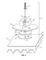
- FIG. 1is an exploded view of a roofing system with a roof attachment assembly according to an embodiment of the present invention.
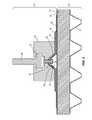
- FIG. 2is a cross-sectional view the roofing system and the roof attachment assembly of FIG. 1 .
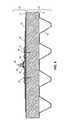
- FIG. 3is an exploded view of an alternative embodiment of the roof attachment assembly of FIG. 1 .
- FIG. 4is an exploded view of a roofing system with a roof attachment assembly according to another embodiment of the present invention.
- FIG. 5is an exploded view of an alternative embodiment of the roofing system with the roof attachment assembly of FIG. 4 .
- FIG. 6is a cross-sectional view the roofing system and the roof attachment assembly of FIG. 4 .
- FIGS. 7-9illustrate an alternative embodiment of a roofing system and a roof attachment assembly according to some embodiments of the present invention.
- FIG. 10illustrates the roof attachment assembly of FIGS. 7-9 .
- phraseology and terminology used herein with reference to device or element orientationare only used to simplify description of embodiments of the present invention and do not alone indicate or imply that the device or element referred to must have a particular orientation.
- terms such as “first” and “second”are used herein for purposes of description and are not intended to indicate or imply relative importance or significance.
- FIGS. 1 and 2illustrate a roofing system 10 including a metal roof deck 12 , a roof substrate 14 (e.g., insulation, tarpaper, plywood or other decking material, and the like) supported on the roof deck 12 , a membrane 16 extending across the substrate 14 (i.e., placed immediately adjacent an upper surface of the substrate 14 or supported on one or more intermediate layers of roofing or sealing material, which in turn are placed on the substrate 14 ).
- the roofing system 10can be utilized on any of a variety of roof types, such as slate roofs, membrane roofs, aluminum roofs, standing seam roofs, tile roofs, shingle roofs, and the like.
- the roofing system 10is operable to support any of a variety of roof-mounted fixtures, such as, for example, snow fences, solar panels, conduit for solar panels, cables for lighting rods, an antenna, signs, billboards, or any of a number of other roof-mountable assemblies.
- roof-mounted fixturessuch as, for example, snow fences, solar panels, conduit for solar panels, cables for lighting rods, an antenna, signs, billboards, or any of a number of other roof-mountable assemblies.
- the roofing system 10can include any of a variety of flashing, seal and bracket arrangements, as will be discussed below.
- a roof attachment assembly 18can be coupled to the roofing system 10 with few or no fasteners extending through the membrane 16 .
- One such roof attachment assembly 18is illustrated in FIGS. 1 and 2 and includes a first membrane pad 20 , a plate 22 having a substantially frustoconical protrusion 24 , a second membrane pad 26 , a bracket 28 having a first recess 30 , a second recess 31 and an aperture 32 extending between the first recess 30 and the second recess 31 , a rivet 34 , and a bolt 36 .
- the rivet 34extends through the first membrane pad 20 , the frustoconical protrusion 24 of the plate 22 , the second membrane pad 26 , and into the aperture 32 of the bracket 28 .
- the bolt 36has a head that substantially mates with the second recess 31 of the bracket 28 .
- roof attachment assembly 18is substantially circular, other shapes are possible.
- the roof attachment assembly 18can be square, ovular, round, rectangular, triangular, pentagonal or other regular or non-regular shape.
- the plate 22can include one or more stiffening ribs or flanges to increase rigidity.
- the plate 22has a top surface 22 A facing the second membrane pad 26 and a bottom surface 22 B facing the first membrane pad 20 .
- the bottom surface 22 B of the platefaces the roof substrate and the top surface 22 A is spaced from the roof substrate.
- the top surface 22 A and/or the bottom surface 22 Bis coated with a material similar to the roof material, such as a membranous material. Embodiments in which both the top surface 22 A and the bottom surface 22 B are coated can omit one or more of the first membrane pad 20 and the second membrane pad 26 .
- the illustrated plate 22is substantially circular, but the plate can be other regular or non-regular shapes.
- the illustrated plate 22is metallic, but is other embodiments the plate is polymeric. In some embodiments, the plate 22 is frangible at a pre-determined force.
- the plate 22extends substantially along a plane.
- the frustoconical protrusion 24 of the plate 22extends away from the roof substrate 14 and defines an aperture 25 extending along an axis 27 .
- the aperture 25is circular, but in other embodiments, can have other regular or irregular shapes.
- the illustrated aperture 25is substantially centered on the upwardly extending protrusion 24 , but other, non-centered embodiments are possible.
- the frustoconical protrusion 24has a diameter in the plane, and the aperture 25 has diameter in a second plane that is substantially parallel to but spaced from the plane.
- the diameter of the aperture 25is less than the diameter of the protrusion 24 , to form a truncated cone or frustoconical shape.
- the protrusion 24can have other shapes and configurations, corresponding to the shape of an underside of the associated bracket 28 .
- the protrusion 24defines a concave interior side 37 , an exterior side 38 and a frustoconical end 39 .
- frustoconicalincludes cones with rounded, flat, non-flat or nearly flat upper portions and truncated cones with rounded, flat, non-flat or nearly flat upper portions.
- the illustrated upwardly extending protrusion 24is circular, but in other embodiments, can be square, D-shaped, triangular, pentagonal, hexagonal, ovular, or other regular or irregular shapes.
- the concave interior side 37 of the protrusion 24may have a number of different shapes and configurations, including but not limited to configurations in which the arch provided by the interior side 37 does not include a uniform radius.
- the first membrane 20 and the second membrane 26have substantially circular shapes, but other shapes of these membranes are possible. In the illustrated embodiment, the diameter of the second membrane 26 is larger than the diameter of the first membrane 20 , but in other embodiments the membranes 20 and 26 can have different diameters.
- the first membrane 20is positioned adjacent to the bottom surface 22 B of the plate 20
- the second membrane 26is positioned adjacent to the top surface 22 A of the plate 22 .
- the first membrane 20 and the second membrane 26include corresponding apertures 29 A and 29 B.
- the apertures 29 A and 29 B of the membranes 20 and 29are substantially aligned with the aperture 25 of the plate 22 , such that that the apertures 29 A and 29 B extend along the axis 27 .
- the bracket aperture 32is substantially aligned with the plate aperture 25 and the apertures 29 A and 29 B of the membranes 20 and 29 , such that that the bracket apertures 32 also extends along the axis 27 .
- the bracket 28is configured to be coupled to the second membrane 26 and is operable to support one or more roof mounted fixtures.
- the bracket 28 illustrated in FIGS. 1-3 .is substantially rectangular, but a square, a circle, or other shaped and sized bracket having a frustoconical aperture can be utilized.
- the illustrated first recess 30 of the bracket 28is substantially frustoconical and matingly receives the frustoconical protrusion 24 at least partially therein.
- the frustoconical protrusion 24can substantially match the shape of the first recess 30 .
- the second recess 31 of the bracket 28is sized to engage the head of the bolt 36 to inhibit rotation of the bolt 36 within the second recess 31 .
- the bracket aperture 32is substantially circular, but other shapes, such as ovular, square, rectangular, hexagonal, and the like are possible.
- the aperture 32is sized to receive the rivet 34 or any fastener, protrusion, or the like therethrough.
- the circular shape of the aperture 32permits flexibility and slight relative movement between the bracket 28 and the rivet 34 , fastener, projection or the like, when installed.
- the plate 22 and the rivet 34are connected to inhibit rotation of the rivet 34 with respect to the plate 22 .
- the plate 22 and the rivet 34can be connected by spot welding, heat welding, forging, indenting the threads with pins or other projections, double-sided tape or other adhesive, or other permanent or semi-permanent connection.
- the bracket 28 and the bolt 36are connected to inhibit rotation of the bolt 36 with respect to the bracket 28 .
- the bracket 28 and the bolt 36can be connected by spot welding, heat welding, forging, indenting the threads with pins or other projections, double-sided tape or other adhesive, or other permanent or semi-permanent connection.
- the roof attachment assembly 18can be coupled to the roofing system 10 with any suitable non-penetrating fastening method, such as welding, adhering, gluing, bonding, and the like.
- the roof attachment assembly 18can be coupled directly to the roof membrane 16 (as shown in FIGS. 1 and 2 ) or can be coupled to a target patch T positioned on the roof membrane 16 of the roof substrate 14 (as shown in FIG. 3 ).
- the roof attachment assembly 18can be coupled to the roofing system above the target patch T (also known as a membrane or a flashing) and a plate P that is secured by a roof-penetrating fastener F.
- the plate Pis substantially circular, but the plate P can be other regular or non-regular shapes.
- the plate Pdefines a counterbore or recess 40 that is configured to accept the fastener F.
- the plate Pdefines a top surface 41 spaced from the roof membrane 16 and the roof substrate 14 .
- One of the sides of the target patch Tis adjacent to the top surface 41 of the plate P, and the other side of the target patch T is adjacent to the first membrane 20 .
- the illustrated embodimentincludes a RhinoBond® plate P and fastener F, but other plates, fasteners and other roof mounting structures can be utilized.
- the diameter of the target patch Tis substantially larger than the diameter of the plate P.
- the target patch T and the plate Pcan have different diameters.
- the fastener Fcan be a bolt, a screw, or any other suitable fastener that allows that plate P to be securely coupled to the roof substrate 14 .
- the target patch Tseals any penetrations caused by the fastener F.
- the roof attachment assembly 18is operable to support any of a variety of roof-mounted fixtures, such as snow guards, snow fences, solar panels, conduit for solar panels, cables for lighting rods, an antenna, signs, billboards, or any other assembly mountable to a roof.
- roof-mounted fixturesare described in detail in commonly-assigned U.S. Pat. No. 5,609,326, filed Jun. 16, 1995, and U.S. Pat. No. 6,526,701, filed Dec. 6, 2000, the contents of both of which are herein incorporated by reference.
- Some suitable brackets that are coupleable to the roof attachment assembly 18are described in detail in commonly-assigned U.S. Patent Application Publication 2011/0120047, filed Oct. 28, 2010, the contents of which are herein incorporated by reference.
- the second membrane pad 26is welded, glued or otherwise adhered to the membrane 16 only around a perimeter of the first membrane pad 20 .
- the plate 22is coated on the top surface 22 A and/or the bottom surface 22 B with a membranous material, an adhesive.
- an adhesivesuch as double-sided tape or a double-sided RhinoBond® plate is connected to the bottom surface 22 B, to adhere the plate 22 directly to the membrane 16 .
- any suitable frangible fastenerother than the rivet 34 can be utilized in the roof attachment assembly 18 .
- frangible fasteneris used herein to describe any fastener having a reasonably predictable and controllable failure load and/or location with respect to the fastener and the fastening system. These fasteners may or may not be threaded.
- pins or other protrusionscan be used to fix the bracket 28 to the fastener.
- the roof attachment assembly 18is separable from the roofing system 10 if a significant separation force and/or torque is applied to the roof attachment assembly 18 .
- the roofingis often damaged. Therefore, it is desirable to design a roof attachment assembly that includes at least one designed built-in failure (i.e., one or more pre-determined breaking points).
- the at least one built-in failureis designed to fail prior to damaging the roofing system 10 .
- Many prior art systemsdesign the roof mount to be as unbreakable as possible. However, roof manufacturers must approve of these roof mount assemblies otherwise, the roof warrantee is voided. Therefore, the present invention provides at least one built-in failure including at least one component of the roof attachment assembly 18 . This component of the roof attachment assembly 18 is designed to fail prior to a failure that may damage the roofing system 10 .
- a first built-in failure in the roof attachment assembly 18is a frangible fastener, such as the illustrated rivet 34 .
- the rivet 34is a blind rivet, such as a POP® rivet manufactured by Emhart® Teknologies. Such rivets can be installed by a user having access to only one side of the pieces to be joined and have predictable failure ratings (i.e., they fail under predetermined levels of force or torque applied to the rivet).
- the rivet 34can be configured to fail under less or significantly less force than is required to tear and/or separate the membranes 16 and 26 .
- the rivet 34can be configured to fail in one or more points of the body of the rivet. In that situation, the rivet 34 of the roof attachment assembly 18 will fail prior to a failure of the membranes 16 or 26 that can damage the roofing system 10 .
- other frangible fastenerscan be utilized in place of the illustrated rivet 34 .
- a second built-in failure in the roof attachment assembly 18is the plate 22 .
- the illustrated plate 22is metallic, so that failure of the illustrated plate 22 would include deformation of the plate 22 adjacent to the aperture 25 to permit the rivet 34 to separate from the plate 22 . Therefore, in that embodiment, the pre-determined breaking point of the plate 22 is at the aperture 25 .
- the plate 22is polymeric, so the plate 22 can also include one or more predetermined breaking points around a perimeter of the plate 22 . Therefore, failure of the plate 22 could include cracking and/or other breaking of the plate 22 to permit the rivet 34 to separate from the plate 22 .
- a third built-in failure in the roof attachment assembly 18is the second membrane 26 .
- the membrane 26is positioned between the plate 22 and the bracket 28 .
- the membrane 26defines a perimeter that is larger than the perimeter of the plate 22 .
- the membrane 26can tear (and thus, fail) if subjected to sufficient force by the plate 22 pulling against the membrane 26 .
- the membrane 26can tear at the central aperture 29 B and/or around the perimeter of the plate 22 . Therefore, the membrane 22 includes one or more predetermined breaking points at the aperture 29 B and/or around the perimeter of the plate 22 .
- a fourth built-in failure in the roof attachment assembly 18is the bolt 36 .
- the bolt 36includes a predetermined breaking point between the head and the shaft of the bolt 36 .
- the bolt 36can include more predetermined breaking points.
- the bolt 36can include a weakening or notch that is designed to fail if subjected to a sufficient force by the roof mounted apparatus pulling off of the bracket 28 .
- only one of the above-identified built-in failures of the roof attachment assembly 18fails at least one the pre-determined breaking point when a force or a torque upon these built-in failures exceeds a pre-determined force. In other embodiments, more than one of the built-in failures of the roof attachment assembly 18 fails. In further embodiments, all of the first, second, third and fourth built-in failures are designed to fail prior to failure of the weld.
- the built-in failures of the roof attachment assembly 18can each have a different failure mode, such that one of the built-in failures fails from a pre-determined torque, another of the built-in failures fails from a pre-determined linear force, and still another of the built-in failures fails from a pre-determined shear force. In other words, the pre-determined force or torque required to fail each of the rivet 34 , the plate 22 , the membrane 26 , and the bolt 26 is different.
- FIGS. 4-6illustrate another construction of a roof attachment assembly 50 having a built-in failure.
- the roof attachment assembly 50can be coupled to a roofing system 10 , which is similar to the previously described roofing system 10 in FIGS. 1-3 .
- the roof attachment assembly 50can be attached to a roofing substrate 14 .
- the roof attachment assembly 50includes a first membrane pad 52 supported on the roof substrate 16 , a plate or a base member 54 having a substantially frustoconical protrusion 56 , a second membrane pad 58 , a bracket 60 , and a fastener 60 (e.g., a bolt).
- a fastener 60e.g., a bolt
- the fastener 62extends through the plate 54 , the second membrane 58 , and the bracket 60 to couple the plate 54 , the second membrane 58 and the bracket 60 .
- the fastener 62can also extend through the roof substrate 16 .
- the first membrane 52is supported on the roof substrate 16 .
- the first membrane 52defines a perimeter that is larger than the perimeter defined by the plate 54 and the second membrane 58 .
- the first membrane 52 and the roof substrate 16can be connected by spot welding, heat welding, forging, indenting the threads with pins or other projections, double-sided tape or other adhesive, by fasteners, or other permanent or semi-permanent connection.
- the length of the first membraneis approximately sixteen inches, but the length can be larger or smaller.
- the illustrated plate 54 of the roof attachment assembly 50is substantially circular, but the plate can be other regular or non-regular shapes.
- the 54is metallic, but is other embodiments the plate is polymeric.
- the plate 54defines a first surface 54 A positioned substantially adjacent the first membrane 52 , and a second surface 55 B spaced from the roof substrate and the first membrane.
- the frustoconical protrusion 56 of the plate 54extends away from the roof substrate 16 along an axis 64 . Further, the first surface 54 A of the plate 54 forms a frustoconical recess 64 and the second surface 54 B forms the frustoconical protrusion 56 .
- the frustoconical protrusion 56 of the plate 54defines an aperture 66 extending along the axis 64 from the first surface 54 A to the second surface 54 B.
- the first aperture 66is substantially centrally positioned in the frustoconical protrusion 56 .
- the plate 54includes a plurality of openings 67 extending from the first surface 54 A through the second surface 54 B.
- the openings 67are configured to accept fasteners 68 (e.g., bolts, screws, etc.) that couple the plate 54 to the first membrane 52 and to the roof substrate 16 of the roofing system 10 .
- the plate 54does not use fasteners 68 , but is coupled to the roof substrate 16 via other suitable non-penetrating methods or mechanisms (e.g., via adhesive, heat welding, forging, etc.).
- the second membrane 58is positioned substantially adjacent the second surface 54 B of the plate 54 and is coupled to the first membrane 52 .
- the second membrane 58defines a surface area or a perimeter that is greater than the surface area of the plate 54 .
- the second membrane 58is deformable to substantially conform to the frustoconical protrusion 56 of the plate 54 when the second membrane 58 attaches to the plate 54 .
- the second membrane 58defines an aperture 70 extending through the second membrane 58 , where the aperture 70 is substantially aligned with the aperture 66 of the plate 54 , such that the aperture 70 extends along the axis 64 .
- the bracket 60 of the roof attachment assembly 50is coupled to the second membrane 58 via the fastener 62 .
- the bracket 60is operable to support at least one roof-mounted assembly.
- the bracket 60defines a first surface 60 A spaced from the second membrane 58 and a second surface 60 B positioned substantially adjacent the second membrane 58 .
- the bracket 60further defines an aperture 72 extending from the first surface 60 A to the second surface 60 B.
- the frustoconical protrusion 56extends at least partially into the bracket aperture 72 . Because the second membrane 58 is deformed by the frustoconical protrusion 56 , the second membrane 58 also extends into the bracket aperture 72 .
- the bracket aperture 72is substantially aligned with the aperture 66 of the plate 54 and the aperture 70 of the second membrane 58 such the bracket aperture 72 extends along the axis 64 .
- the fastener 62 of the roof attachment assembly 50is oriented along the axis 64 and extends through the aperture 66 of the plate 54 , the aperture 70 of the second membrane 58 , and the bracket aperture 72 to couple the plate 54 to the second membrane 58 and to the bracket 60 .
- the diameter defined by the plate 54is greater than the diameter defined by the aperture 66 of the plate 54 and the diameter defined by the aperture 70 of the second membrane 58 .
- the roof attachment assembly 50is constructed without the bracket 60 or the first membrane 52 (see FIG. 4 ).
- the plate 54is directly positioned on the roof substrate 16 of the roofing system 10 .
- the plate 54can be heat welded, or otherwise coupled, to the second membrane 58 .
- the plate 54can be attached to the roof substrate 16 via the fasteners 68 or by any other reasonable means.
- the fastener 62extends through the aperture 66 of the plate 54 and the aperture 70 of the second membrane 58 to couple the plate to the second membrane 58 .
- the fastener 62 of the roof attachment assembly 50is configured to accept a compression fitting 74 (see FIG. 6 ).
- the fastener 74further defines an attachment point 76 exposed for mechanical fastening.
- the roof attachment assembly 50also includes at least one designed built-in failure (i.e., one or more pre-determined breaking points) that is designed to fail prior to damaging the roofing system 10 .
- a first built-in failure in the roof attachment assembly 50is the plate 54 . Failure of the illustrated plate 54 would include deformation of the plate 54 adjacent to the aperture 66 to permit the fastener 62 to separate from the plate 54 (i.e., when the plate is metal). Therefore, in that embodiment, the pre-determined breaking point of the plate 54 is at the aperture 66 .
- the plate 54can also include one or more predetermined breaking points around a perimeter of the plate 54 .
- failure of the plate 54could include cracking and/or other breaking of the plate 54 to permit the plate 54 to separate from the first membrane 52 .
- the plate 64When the plate 64 is coupled to the roof substrate 16 via fasteners 68 , the plate may not include any pre-determined breaking points because breaking the plate 64 at the fasteners 68 may damage the roofing system 10 .
- a second built-in failure in the roof attachment assembly 50is the second membrane 58 .
- the membrane 58is coupled to the plate 22 and the bracket 60 .
- the second membrane 58can tear and fail if subjected to sufficient force by the plate 54 pulling against the membrane 58 .
- the second membrane 58can tear at the central aperture 70 and/or around the perimeter of the plate 54 . Therefore, the second membrane 58 includes one or more predetermined breaking points at the aperture 70 and/or around the perimeter of the plate 54 .
- a third built-in failure in the roof attachment assembly 50is the fastener 62 .
- the fastener 62includes a predetermined breaking point between the head and the shaft of the fastener 62 . In other embodiments, the fastener 62 can include more predetermined breaking points.
- the roof attachment assembly 50is constructed such that more than one or all of the built-in failures fail prior to failure of the weld.
- each of the built-in failures of the roof attachment assembly 50can have a different failure mode. For example, one of the built-in failures fails from a pre-determined torque, another of the built-in failures fails from a pre-determined linear force, and still another of the built-in failures fails from a pre-determined shear force.
- FIGS. 7-10illustrate another construction of a roofing system 110 including a metal roof deck 112 , a roof substrate 114 (e.g., insulation, tarpaper, plywood or other decking material, and the like) supported on the roof deck 112 , a membrane 116 extending across the substrate 114 (i.e., placed immediately adjacent an upper surface of the substrate 114 or supported on one or more intermediate layers of roofing or sealing material, which in turn are placed on the substrate 114 ).
- the roofing system 110can be utilized on any of a variety of roof types, such as slate roofs, membrane roofs, aluminum roofs, standing seam roofs, tile roofs, shingle roofs, and the like. Further, the roofing system 110 possesses all characteristics of the previously described roofing systems 10 shown in FIGS. 1-6 .
- a roof attachment assembly 118can be coupled to the roofing system 110 with few or no fasteners extending through the membrane 116 .
- the roof attachment assembly 118includes a plate (also called a base member) 120 having an upwardly extending fastener 122 , a membrane pad 124 , a compression washer 126 having a substantially frustoconical aperture 128 , a spacer 130 , a flashing 132 and a hose clamp 134 .
- the roof attachment assembly 118can be coupled to the roofing system 110 with any suitable non-penetrating fastening method, such as welding, adhering, gluing, bonding, and the like.
- the roof attachment assembly 118is operable to support any of a variety of roof-mounted fixtures.
- the illustrated roof attachment assembly 118is substantially square, other shapes are possible.
- the roof attachment assembly 118can be round, ovular, rectangular, triangular, pentagonal or other regular or non-regular shape.
- the plate 120 of the roof attachment assembly 118can include a substantially frustoconical protrusion 136 defining an aperture 137 .
- the fastener 122extends through the frustoconical protrusion 136 and the aperture 137 of the plate 120 .
- the frustoconical protrusion 136extends at least partially into the frustoconical aperture 128 of the washer 126 .
- the washer 126can be circular, square, ovular, pentagonal or any other suitable size and shape. In some embodiments, the washer 126 can be omitted.
- the plate 120 and the upwardly extending fastener 122are formed as a single unitary piece. In some embodiments, the plate 120 and the upwardly extending fastener 122 are formed as separate pieces and joined during installation.
- the plate 120can include one or more stiffening ribs or flanges to increase rigidity. Other type of plates can be utilized in place of plate 120 and the roof attachment assembly 118 can include more than one plate 120 .
- the plate 120has a top surface 120 A facing the membrane pad 124 and a bottom surface 120 B facing the roof membrane 116 .
- the top surface 120 A and/or the bottom surface 120 Bis coated with a material similar to the roof material, such as a membranous material. Embodiments in which both the top surface 120 A and the bottom surface 120 B are coated can omit the membrane pad 124 .
- the plate 120is coupled to the roof by any non-penetrating fastening method, such as welding, adhering, gluing, bonding, and the like. In other embodiments, the plate 120 can be coupled to the roof by using fasteners (not shown).
- the plate 120is coupled to the roof membrane 116 by any suitable non-penetrating method, and then the membrane pad 124 is coupled to the plate 120 .
- the plate 120is coupled to the membrane pad 124 to form a single unit, and the single unit is coupled to the roof membrane 116 by any suitable non-penetrating method.
- the membrane 124has a substantially rectangular form, but other shapes of the membrane 124 are also possible.
- the membrane 124is positioned adjacent to the top surface 120 A of the plate 120 , and defines an aperture 125 that substantially aligns with the aperture 137 of the plate 120 and the frustoconical aperture 128 of the washer 126 .
- the membrane 124defines a top surface 124 A and a bottom surface 124 B.
- the pipe flashing 132is positioned adjacent to the top surface 124 A of the membrane 124 .
- the illustrated pipe flashing 132comprises metal, but in other embodiments, other material(s) can also be.
- the pipe flashing 132can include a coating on top surface 132 A and/or a bottom surface 132 B. In embodiments that include a coating on the bottom surface 132 B, the coating can be adhered or otherwise coupled to the membrane 124 .
- the pipe flashing 132defines a projection area 133 that is configured to accept at least a portion of the frustoconical protrusion 136 and the washer 126 .
- the pipe flashing 132further defines a flashing aperture 138 that substantially aligns with the aperture 125 of the membrane 124 , the aperture 137 of the plate 120 , and the frustoconical aperture 128 of the washer 126 .
- the flashing aperture 138has a diameter that is larger than the diameter of apertures 125 , 137 , and 125 , such that it allows the spacer 130 to pass through the aperture 138 .
- the perimeters of the membrane 124 and the pipe flashing 132are substantially equal, and both perimeters are larger than the perimeter of the plate 120 . In other embodiment, these elements of the roof attachment assembly 118 can have different perimeters.
- the fastener 122extends through the aperture 137 of the frustoconical protrusion 136 , the frustoconical aperture 128 of the washer 126 , and engages the spacer 130 .
- the spacer 130extends through the aperture 138 of the flashing 132 .
- other fastening apparatuses and methods, or combinations of fastening apparatusesare utilized in place of washer 126 , spacer 130 , flashing 132 and hose clamp 134 .
- One suitable non-penetrating fastening methodincludes providing an adhesive on any of the roof membrane 116 , the plate 120 , the membrane 124 and the flashing 132 .
- one or more of the roof membrane 116 , the plate 120 , the membrane 124 and the flashing 132comprises a meltable material that can be construed as an adhesive.
- a separate adhesiveis applied to the top 120 A and/or the bottom 120 B of the plate 120 .
- the roof attachment assembly 118is positioned on the roof membrane 116 , and is then heated by a heat source, such as by an induction coil. The adhesive at least partially melts in response to the heat source. Once solidified, the adhesive can couple the roof attachment assembly 118 to the roof membrane 116 .
- Other suitable attachment methodsare possible, such as welding, gluing, adhering, bonding and the like, and the present method is given by way of example only.
- the membrane 124is adhered to the roof membrane 116 to couple the roof attachment assembly 118 to the roof 110 .
- the plate 120is adhered to the roof membrane 116 to couple the roof attachment assembly 118 to the roof 110 .
- the membrane 124is adhered to the plate 120 and the plate 120 is adhered to the roof membrane 116 to couple the roof attachment assembly 118 to the roof 110 .
- the membrane 124is adhered to the plate 120 , and the membrane 124 is adhered to the roof membrane 116 to couple the roof attachment assembly 118 to the roof 110 .
- both the plate 120 and the membrane 124are adhered to the roof membrane 116 to couple the roof attachment assembly 118 to the roof 110 .
- the roof attachment assembly 118also includes at least one designed built-in failure (i.e., one or more pre-determined breaking points) that is designed to fail prior to damaging the roofing system 110 .
- a first built-in failure in the roof attachment assembly 118is the plate 120 . Failure of the plate 120 would include deformation of the plate 120 adjacent to the aperture 137 to permit the fastener 122 to separate from the plate 120 (i.e., when the plate is metal). Therefore, in that embodiment, the pre-determined breaking point of the plate 120 is at the aperture 137 .
- the plate 120can also include one or more predetermined breaking points around a perimeter of the plate 120 . Therefore, failure of the plate 120 could include cracking and/or other breaking of the plate 54 to permit the plate 120 to separate from the roof membrane 116 .
- a second built-in failure in the roof attachment assembly 118is the membrane 124 .
- the membrane 124is coupled to the plate 120 and the pipe flashing 132 .
- the membrane 124can tear and fail if subjected to sufficient force by the plate 120 pulling against the membrane 124 .
- the membrane 124can tear at the central aperture 125 and/or around the perimeter of the plate 120 . Therefore, the membrane 124 includes one or more predetermined breaking points at the aperture 125 and/or around the perimeter of the plate 120 .
- a third built-in failure in the roof attachment assembly 118is the fastener 122 .
- the fastener 122includes a predetermined breaking point between the head and the shaft of the fastener 122 .
- the fastener 122can include more predetermined breaking points.
- the fastener 122can include a predetermined breaking point at the area where the fastener 122 engages the spacer 130 .
- a fourth built-in failure in the roof attachment assembly 118is the spacer 130 .
- the spacercan be configured to fail under less or significantly less force than is required to tear and/or separate the membrane 124 or the plate 120 .
- the spacer 130can be configured to fail at the attachment point with the fastener 122 or at other portions of the spacer 130 . In that situation, the spacer will fail prior to a failure of the membrane 124 or the plate 120 to prevent damage the roofing system 110 .
- the roof attachment assembly 118can include more built-in failures.
- the washer 126 and the flashing 132can also include predetermined breaking points that allow the washer 126 and the flashing 132 to fail prior to failure of the membrane 124 or the plate 120 to protect the roofing system 110 from damage.
- the roof attachment assembly 118is constructed such that more than one or all of the built-in failures fail prior to failure of the connection between the roof attachment assembly 118 and the roofing system 110 .
- each of the built-in failures of the roof attachment assembly 118can have a different failure mode. For example, one of the built-in failures fails from a pre-determined torque, another of the built-in failures fail from a pre-determined linear force, and still another of the built-in failures fail from a pre-determined shear force.
Landscapes
- Engineering & Computer Science (AREA)
- Physics & Mathematics (AREA)
- Sustainable Development (AREA)
- Sustainable Energy (AREA)
- Architecture (AREA)
- Civil Engineering (AREA)
- Structural Engineering (AREA)
- Life Sciences & Earth Sciences (AREA)
- General Physics & Mathematics (AREA)
- Theoretical Computer Science (AREA)
- Thermal Sciences (AREA)
- Chemical & Material Sciences (AREA)
- Combustion & Propulsion (AREA)
- Mechanical Engineering (AREA)
- General Engineering & Computer Science (AREA)
- Roof Covering Using Slabs Or Stiff Sheets (AREA)
Abstract
Description
Claims (35)
Priority Applications (3)
| Application Number | Priority Date | Filing Date | Title |
|---|---|---|---|
| US13/272,604US8683751B2 (en) | 2011-07-08 | 2011-10-13 | Roof mount having built-in failure |
| PCT/US2012/033764WO2013009375A1 (en) | 2011-07-08 | 2012-04-16 | Roof mount having built-in failure |
| DE112012002882.1TDE112012002882T5 (en) | 2011-07-08 | 2012-04-16 | Roof attachment with integrated break point |
Applications Claiming Priority (2)
| Application Number | Priority Date | Filing Date | Title |
|---|---|---|---|
| US201161505670P | 2011-07-08 | 2011-07-08 | |
| US13/272,604US8683751B2 (en) | 2011-07-08 | 2011-10-13 | Roof mount having built-in failure |
Publications (2)
| Publication Number | Publication Date |
|---|---|
| US20130009025A1 US20130009025A1 (en) | 2013-01-10 |
| US8683751B2true US8683751B2 (en) | 2014-04-01 |
Family
ID=47438045
Family Applications (1)
| Application Number | Title | Priority Date | Filing Date |
|---|---|---|---|
| US13/272,604ActiveUS8683751B2 (en) | 2011-07-08 | 2011-10-13 | Roof mount having built-in failure |
Country Status (3)
| Country | Link |
|---|---|
| US (1) | US8683751B2 (en) |
| DE (1) | DE112012002882T5 (en) |
| WO (1) | WO2013009375A1 (en) |
Cited By (27)
| Publication number | Priority date | Publication date | Assignee | Title |
|---|---|---|---|---|
| US20130186014A1 (en)* | 2012-01-25 | 2013-07-25 | Steven James Wall | Raised flooring apparatus and system |
| US8938932B1 (en)* | 2013-12-13 | 2015-01-27 | Quality Product Llc | Rail-less roof mounting system |
| US20150326171A1 (en)* | 2008-05-08 | 2015-11-12 | Sustainable Technologies, Llc | Roof Mounted Installation Solar Power System |
| US9416541B2 (en)* | 2014-04-29 | 2016-08-16 | Renewable Elements, Llc | Fixture support for membrane roof |
| US9515599B2 (en) | 2013-09-17 | 2016-12-06 | Lumos Lsx, Llc | Photovoltaic panel mounting rail with integrated electronics |
| US20170096836A1 (en)* | 2015-10-01 | 2017-04-06 | Long Fence | Anti-scale fence systems |
| US9935356B2 (en)* | 2016-05-31 | 2018-04-03 | Imagineering Plus Plus, LLC | Satellite dish mount device |
| US9985579B2 (en) | 2016-04-12 | 2018-05-29 | Preformed Line Products Co. | Mounting assembly for mounting a solar panel |
| US10097133B2 (en) | 2016-04-14 | 2018-10-09 | Shahriar Shamloo Aliabadi | Racking system for installing solar panels |
| US20190169856A1 (en)* | 2011-02-25 | 2019-06-06 | Dustin M.M. Haddock | Mounting device for building surfaces having elongated mounting slot |
| US10601360B2 (en) | 2017-09-08 | 2020-03-24 | Unirac Inc. | Replacement tile mount for mounting solar panels on tile roofs |
| US10640980B2 (en) | 2016-10-31 | 2020-05-05 | Rmh Tech Llc | Metal panel electrical bonding clip |
| US20200248457A1 (en)* | 2019-02-04 | 2020-08-06 | Omg, Inc. | Roof Mount Assembly with Stabilized Fastener Matrix |
| US10859292B2 (en) | 2016-07-29 | 2020-12-08 | Rmh Tech Llc | Trapezoidal rib mounting bracket with flexible legs |
| US10903785B2 (en) | 2018-03-21 | 2021-01-26 | Rmh Tech Llc | PV module mounting assembly with clamp/standoff arrangement |
| US10948002B2 (en) | 2018-12-14 | 2021-03-16 | Rmh Tech Llc | Mounting device for nail strip panels |
| US11041310B1 (en) | 2020-03-17 | 2021-06-22 | Rmh Tech Llc | Mounting device for controlling uplift of a metal roof |
| US11085484B2 (en)* | 2016-09-23 | 2021-08-10 | Sunpower Corporation | Water sealing surface attachment |
| US11333179B2 (en) | 2011-12-29 | 2022-05-17 | Rmh Tech Llc | Mounting device for nail strip panels |
| US11352793B2 (en) | 2020-03-16 | 2022-06-07 | Rmh Tech Llc | Mounting device for a metal roof |
| US11774143B2 (en) | 2017-10-09 | 2023-10-03 | Rmh Tech Llc | Rail assembly with invertible side-mount adapter for direct and indirect mounting applications |
| US11859870B2 (en) | 2019-06-19 | 2024-01-02 | Patton Engineering, Inc. | Methods and systems for rigidly attaching components to roof structures |
| US11996802B2 (en) | 2019-06-10 | 2024-05-28 | Origami Solar, Inc. | Methods and systems for folded frame solar panels |
| USD1053698S1 (en)* | 2020-07-17 | 2024-12-10 | Voidform Products, Llc | Spacer bracket |
| US12203496B2 (en) | 2020-07-09 | 2025-01-21 | Rmh Tech Llc | Mounting system, device, and method |
| USD1075493S1 (en) | 2022-07-06 | 2025-05-20 | Rmh Tech Llc | Clamp for a photovoltaic module mounting assembly |
| US20250223995A1 (en)* | 2015-07-29 | 2025-07-10 | Ironridge, Inc. | Bracket Mount for Securing Solar Panel Rail Guides on a Roof |
Families Citing this family (30)
| Publication number | Priority date | Publication date | Assignee | Title |
|---|---|---|---|---|
| US9447988B2 (en) | 2010-01-25 | 2016-09-20 | Rillito Rive Solar, LLC | Roof mount assembly |
| US10054336B2 (en) | 2010-03-03 | 2018-08-21 | Robert M. M. Haddock | Photovoltaic module mounting assembly |
| US9309911B1 (en)* | 2012-01-23 | 2016-04-12 | K & R Industries Inc. | Cap nail |
| US9175478B2 (en) | 2012-05-29 | 2015-11-03 | Vermont Slate & Copper Services, Inc. | Snow fence for a solar panel |
| AT513027B1 (en)* | 2012-08-24 | 2014-01-15 | Traxler Manfred | Device for fastening objects |
| US9163861B2 (en) | 2012-10-01 | 2015-10-20 | Georgia Tech Research Corporation | Solar panel truss mounting systems and methods |
| GB2511340A (en) | 2013-02-28 | 2014-09-03 | Latchways Plc | Membrane bonded anchor arrangement |
| US9973142B2 (en) | 2013-03-06 | 2018-05-15 | Vermont Slate and Copper Services, Inc. | Snow fence for a solar panel |
| US8776456B1 (en) | 2013-10-21 | 2014-07-15 | Sunmodo Corporation | Solar panel tile roof mounting device |
| US20150179848A1 (en)* | 2013-12-24 | 2015-06-25 | General Electric Company | Deployable solar panel system |
| MX375846B (en)* | 2014-01-16 | 2025-03-06 | Jonathan Port | APPARATUS AND METHODS FOR FIXING ROOF BRACES AND STRUCTURAL MEMBERS FOR ROOFS. |
| US9551509B2 (en) | 2014-01-16 | 2017-01-24 | Jonathan Port | Apparatuses and methods for fastening roofing strapsand structural members to roofs |
| US11012023B2 (en)* | 2014-04-07 | 2021-05-18 | EcoFasten Solar, LLC | Solar panel coupling stabilization system |
| US9431953B2 (en) | 2014-10-31 | 2016-08-30 | Rillito River Solar, Llc | Height adjustment bracket for roof applications |
| US9985575B2 (en) | 2014-04-07 | 2018-05-29 | Rillito River Solar, Llc | Height adjustment bracket for roof applications |
| US12107530B2 (en) | 2014-04-07 | 2024-10-01 | EcoFasten Solar, LLC | Height adjustment bracket for roof applications |
| US9422720B2 (en)* | 2014-07-31 | 2016-08-23 | Renewable Elements, Llc | Non-penetrating roof mount for a membrane roof |
| JP6633916B2 (en)* | 2015-01-29 | 2020-01-22 | 三ツ星ベルト株式会社 | Snow stopper support bracket and waterproof structure for roof with snow stopper structure |
| US9874021B2 (en)* | 2015-08-28 | 2018-01-23 | Solarcity Corporation | Tile and slate roof flashing systems |
| US10277162B1 (en)* | 2016-08-16 | 2019-04-30 | Moti Atia | Mounting apparatus to secure a solar panel rail to stone-coated metal tile roofs |
| US10469023B2 (en) | 2016-09-12 | 2019-11-05 | EcoFasten Solar, LLC | Roof mounting system |
| US10781587B2 (en) | 2016-12-14 | 2020-09-22 | Solsera, Inc. | Structural attachment sealing system |
| US11035130B1 (en)* | 2019-02-01 | 2021-06-15 | Daniel Efrain Arguelles | Synthetic mechanically attached roof underlayment system |
| JP2020165141A (en)* | 2019-03-28 | 2020-10-08 | 出光興産株式会社 | Fixtures for panel modules |
| US11746821B2 (en) | 2019-04-26 | 2023-09-05 | Solsera, Inc. | Flat roof mounting device |
| US10767684B1 (en) | 2019-04-26 | 2020-09-08 | Solsera, Inc. | Flat roof mounting device |
| FR3096998B1 (en)* | 2019-06-05 | 2021-10-22 | Smac | Fastening system for panels on a sealed roof, installation process |
| US11962137B2 (en) | 2020-04-21 | 2024-04-16 | Unirac Inc. | Electric junction box mount apparatus |
| US11695369B1 (en)* | 2022-09-16 | 2023-07-04 | Sunrun Inc. | Surface mount assemblies for a solar panel system |
| EP4582649A1 (en)* | 2024-01-02 | 2025-07-09 | CWL Patent AB | Fastening plate for fastening roof equipment at a roof surface |
Citations (123)
| Publication number | Priority date | Publication date | Assignee | Title |
|---|---|---|---|---|
| US473512A (en) | 1892-04-26 | Snow-iron for roofs | ||
| US756884A (en) | 1903-07-07 | 1904-04-12 | William W Parry | Snow-guard for roofs. |
| US1646923A (en) | 1926-04-07 | 1927-10-25 | William E Martens | Shingle-scaffold bracket |
| US1925263A (en) | 1931-08-22 | 1933-09-05 | Levow David | Snowguard |
| US2079768A (en) | 1935-06-27 | 1937-05-11 | Levow David | Snow guard |
| CH204783A (en) | 1939-01-16 | 1939-05-31 | Oppliger Leon | Snow guard for metal roofs. |
| US2349467A (en) | 1943-05-19 | 1944-05-23 | Thomas L Scott | Gutter hanger |
| GB666147A (en) | 1949-02-07 | 1952-02-06 | Ernest James Sutton | Improvements in roof snow guard brackets |
| US2890664A (en) | 1951-08-02 | 1959-06-16 | Pollock Helen | Gutter and gutter support |
| US2925976A (en) | 1958-11-25 | 1960-02-23 | Russell S Martin | Adjustable eaves trough supports |
| US3141532A (en) | 1960-07-21 | 1964-07-21 | Inland Steel Products Company | Structural supports for mounting sheet metal panels |
| US3182762A (en) | 1963-03-18 | 1965-05-11 | Trumbull Dev Corp | Post for a bridge railing |
| US3633862A (en) | 1970-05-28 | 1972-01-11 | Hubert Ind Ltd | Safety rail |
| US3880405A (en) | 1974-01-18 | 1975-04-29 | Butler Manufacturing Co | Portable, personnel guard rail |
| US3937121A (en) | 1975-04-14 | 1976-02-10 | Pitney-Bowes, Inc. | Double break-off screw |
| US3998019A (en) | 1975-08-18 | 1976-12-21 | Illinois Tool Works Inc. | Roof panel fastener and joint construction |
| US4226058A (en) | 1978-11-06 | 1980-10-07 | Goettl Air Conditioning, Inc. | Anchor for roof mounted equipment |
| US4269012A (en) | 1979-02-01 | 1981-05-26 | The Binkley Company | Standing seam roof, panel therefor, and method of installation |
| US4321745A (en) | 1980-04-28 | 1982-03-30 | Energy Design Corp. | Sealing method |
| US4325178A (en) | 1980-06-05 | 1982-04-20 | General Electric Company | Screw anchoring device and method |
| US4348846A (en) | 1980-10-02 | 1982-09-14 | Butler Manufacturing Company | Insulated roof |
| US4367864A (en) | 1980-02-22 | 1983-01-11 | Eldeen Gene H | Newel post assembly |
| US4404962A (en) | 1982-02-11 | 1983-09-20 | Raybend Associates | Large format film glazed solar collector |
| US4554773A (en) | 1984-04-30 | 1985-11-26 | Conley John L | Device and method for securing overlapping corrugated sheets |
| USD293203S (en) | 1985-09-09 | 1987-12-15 | Hertensteiner Thomas J | Stud mount, pipe support bracket |
| USD294904S (en) | 1986-03-03 | 1988-03-29 | Bleskachek Gerald N | Disposable razor holder |
| US4744187A (en) | 1987-01-27 | 1988-05-17 | The Firestone Tire & Rubber Company | Mechanical roof fastener |
| US4763456A (en) | 1987-08-03 | 1988-08-16 | Giannuzzi Louis | Roof anchor and stress plate assembly |
| US4778702A (en) | 1985-09-04 | 1988-10-18 | Physical Systems, Inc. | Adhesive attachment and mounting fixture |
| DE3716491A1 (en) | 1987-05-16 | 1988-12-01 | Siegfried Wittwer | Snow trap |
| US4796403A (en) | 1987-08-28 | 1989-01-10 | Metal Building Components Incorporated | Articulating roofing panel clip |
| DE3723020A1 (en) | 1987-07-11 | 1989-01-19 | Siegfried Wittwer | Snow stop for profiled-sheet-metal roof |
| CH671063A5 (en) | 1988-03-08 | 1989-07-31 | Kuenzle Apparatebau Ag | Building roof snow trap - accommodates tubes in holder with recesses open towards ridge |
| US4892429A (en) | 1987-08-03 | 1990-01-09 | Giannuzzi Louis | Roof anchor and stress plate assembly |
| US4903997A (en) | 1981-04-27 | 1990-02-27 | Oatey Co. | Roof flashing |
| US4927305A (en) | 1988-09-02 | 1990-05-22 | Peterson Charles D | Tightening device for threaded connectors |
| US5082412A (en) | 1990-12-03 | 1992-01-21 | Illinois Tool Works Inc. | Roofing washer |
| US5127205A (en) | 1990-11-05 | 1992-07-07 | Eidson Carson J | Support clip for roofing panels and associated system |
| US5207043A (en) | 1988-11-07 | 1993-05-04 | Mcgee Brian P | Masonry connector |
| US5217191A (en) | 1992-07-21 | 1993-06-08 | Smith Robert L | Pipe hangers or the like |
| US5228248A (en) | 1992-07-13 | 1993-07-20 | Haddock Robert M M | Mounting device for building structures |
| US5353473A (en) | 1993-04-12 | 1994-10-11 | Sherick Thomas G | Bottom fixture for overhead garage doors |
| US5431372A (en) | 1993-10-04 | 1995-07-11 | Denpak Building Products, Inc. | Safety post assembly |
| USD368648S (en) | 1994-08-16 | 1996-04-09 | Losier Richard J | Bracket for optical and carrier cables |
| US5528872A (en) | 1994-04-26 | 1996-06-25 | Rotter; Martin J. | Nail |
| US5547226A (en) | 1995-06-26 | 1996-08-20 | Wentworth; Claudia H. | Household filing system |
| US5557903A (en) | 1994-08-01 | 1996-09-24 | Haddock; Robert M. M. | Mounting clip for paneled roof |
| US5609326A (en) | 1995-06-16 | 1997-03-11 | Stearns; Brian C. | Impervious membranous roof snow fence system |
| US5613328A (en) | 1995-02-21 | 1997-03-25 | Alley; F. William | Snow guard for a metal roof |
| US5685508A (en) | 1994-01-18 | 1997-11-11 | Portable Pipe Hangers, Inc. | Pipe hanging and rooftop load supporting system |
| US5687936A (en) | 1995-06-07 | 1997-11-18 | Wilson; Dennis E. | Gutter bracket |
| US5692352A (en) | 1984-01-04 | 1997-12-02 | Harold Simpson, Inc. | Roof panel standing seam assemblies |
| USD388136S (en) | 1994-12-05 | 1997-12-23 | Meccano, S.A. | Construction toy element |
| US5715640A (en) | 1992-07-13 | 1998-02-10 | Haddock; Robert M. M. | Mounting device for controlling uplift of a metal roof |
| US5797232A (en) | 1996-08-15 | 1998-08-25 | Illinois Tool Works Inc. | Gripping plate for attaching roofing membrane |
| US5813649A (en) | 1996-03-13 | 1998-09-29 | Simula, Inc. | Energy-absorbing deformable bracket |
| US5873201A (en) | 1997-10-22 | 1999-02-23 | Lonnie Naefke | Roof structure support device |
| US5882043A (en) | 1997-10-14 | 1999-03-16 | Exterior Research & Design, Llc | Roof drain adapter |
| USD409078S (en) | 1998-05-01 | 1999-05-04 | Bolt Stanley E | Decorative joist hanger |
| USD426453S (en) | 1999-02-22 | 2000-06-13 | Stearns Brian C | Roof bracket basestand |
| USD428799S (en) | 1999-08-24 | 2000-08-01 | Stearns Brian C | Roof bracket brace component |
| USD430005S (en) | 1999-08-24 | 2000-08-29 | Pipeholding unit | |
| US6193455B1 (en) | 1999-09-28 | 2001-02-27 | Illinois Tool Works Inc. | Blind screw anchor and system |
| US6354046B1 (en) | 2000-07-29 | 2002-03-12 | Michael R Swearingen | Skylight membrane with diverter |
| US6360491B1 (en) | 2000-01-14 | 2002-03-26 | Stanley A. Ullman | Roof support system for a solar panel |
| US20020035811A1 (en) | 2000-05-30 | 2002-03-28 | Thomas Heuel | Fastening device for fastening roof components to a connecting area of two adjacent roof sections of an aluminum roof |
| US6414237B1 (en) | 2000-07-14 | 2002-07-02 | Astropower, Inc. | Solar collectors, articles for mounting solar modules, and methods of mounting solar modules |
| US20020088196A1 (en) | 2001-01-11 | 2002-07-11 | Haddock Robert M. M. | Multi-piece clamp for standing seams |
| US20020131842A1 (en) | 1998-12-11 | 2002-09-19 | Novator Ab | Fastening assembly and method for fastening a multi-layered laminate together |
| US6453623B1 (en) | 2000-01-24 | 2002-09-24 | Roofers - Annex Inc. | Roof snow barrier |
| US6470629B1 (en) | 1999-05-17 | 2002-10-29 | Robert M. Haddock | Mounting system and adaptor clip |
| US6514005B2 (en) | 2000-02-14 | 2003-02-04 | Hitachi, Ltd. | Apparatus for installing a material which is processed by using chemicals |
| US6526701B2 (en) | 2000-07-03 | 2003-03-04 | Vermont Slate & Copper Services, Inc. | Roof mount |
| US6536729B1 (en) | 1999-05-17 | 2003-03-25 | Robert M. M. Haddock | Bracket assembly including a reservoir |
| US20030101662A1 (en) | 2000-01-14 | 2003-06-05 | Ullman Stanley A. | Mounting system for supporting objects |
| US20030177706A1 (en) | 2000-01-14 | 2003-09-25 | Ullman Stanley A. | Mounting system for supporting objects |
| US20040173373A1 (en) | 2003-03-07 | 2004-09-09 | Wentworth Stuart Hazard | Locking device for male/female electrical cable connectors |
| US6868647B2 (en) | 2000-08-15 | 2005-03-22 | Arvo Poldmaa | Roof anchor method and apparatus |
| US20060010786A1 (en) | 2004-07-13 | 2006-01-19 | Rogers Craig C | Roof snow stop |
| US7069698B2 (en) | 2002-04-29 | 2006-07-04 | Nee Stephen F | Method and apparatus for coupling structures to roofing |
| US7174677B1 (en) | 2003-09-17 | 2007-02-13 | Amerimax Home Products, Inc. | Snow guard for shingled roofs |
| US7260918B2 (en) | 2001-07-20 | 2007-08-28 | Unirac, Inc. | Apparatus and method for positioning a module on an object |
| US20070245636A1 (en) | 2006-04-25 | 2007-10-25 | Ayer Sydney L | Snow guard for roofs |
| US20070266672A1 (en) | 2006-05-19 | 2007-11-22 | Solar Century Holdings Limited | Solar panel roof mounting system |
| US20070289233A1 (en) | 2006-06-20 | 2007-12-20 | Haddock Robert M M | Crowning panel assembly |
| US20080000173A1 (en) | 2006-03-09 | 2008-01-03 | Sunpower Corporation | PV Module Mounting Method and Mounting Assembly |
| US20080087275A1 (en) | 2006-10-16 | 2008-04-17 | Rovshan Sade | Solar Installation System |
| US20080190047A1 (en) | 2007-02-08 | 2008-08-14 | Allen Gary E | Solar Panel Roof Kit |
| US20080245404A1 (en) | 2007-04-05 | 2008-10-09 | Deliddo Jack P | Apparatus and method for attaching solar panels to roof system surfaces |
| US20080313976A1 (en) | 2007-02-08 | 2008-12-25 | Luma Resources, Llc | Solar Panel Roof Kit |
| US7600349B2 (en) | 2003-02-26 | 2009-10-13 | Unirac, Inc. | Low profile mounting system |
| US20090309388A1 (en) | 2008-06-12 | 2009-12-17 | Terrie Ellison | Mounting arrangement for mounting cladding to vehicle body |
| US7686268B2 (en) | 2005-05-19 | 2010-03-30 | Sharp Kabushiki Kaisha | Structure fixing apparatus including support device |
| US7703256B2 (en) | 2004-04-05 | 2010-04-27 | Haddock Robert M M | Multi-piece attachment mounting clamp for trapezoidal rib profile panels |
| USD617174S1 (en) | 2009-01-21 | 2010-06-08 | D Three Enterprises, Llc | Interlocking support post |
| US7730901B2 (en) | 2005-11-01 | 2010-06-08 | Wcm Industries, Inc. | Hydrant roof mount |
| US7758011B2 (en) | 2007-06-06 | 2010-07-20 | Robert M. M. Haddock | Adjustable mounting assembly for standing seam panels |
| US7762027B1 (en) | 2006-09-28 | 2010-07-27 | Wentworth Stuart H | System for attaching an article to a roof and method of use |
| US20100192505A1 (en) | 2009-02-05 | 2010-08-05 | D Three Enterprises, Llc | Interlocking Shape For Use in Construction Members |
| US7789365B2 (en) | 2005-07-12 | 2010-09-07 | Hilti Aktiengesellschaft | Grid-holding element |
| US20100236155A1 (en) | 2009-03-21 | 2010-09-23 | Carlo John Lanza | Protective covering for roof mounted systems |
| US20100307074A1 (en) | 2010-03-19 | 2010-12-09 | Brian Cecil Stearns | Roofing system and method |
| US7857269B2 (en) | 2006-11-29 | 2010-12-28 | Pvt Solar, Inc. | Mounting assembly for arrays and other surface-mounted equipment |
| US7861485B1 (en)* | 2007-06-26 | 2011-01-04 | Wentworth Stuart H | Method for installing a stanchion on a tile roof and system therefor |
| US7866099B2 (en) | 2005-04-07 | 2011-01-11 | Sharp Kabushiki Kaisha | Mounting structure of solar cell module |
| US7900413B2 (en) | 2009-04-22 | 2011-03-08 | Joel Stanley | Method of securing flexible solar panel to PVC roofing membrane |
| WO2011032134A2 (en) | 2009-09-14 | 2011-03-17 | Stanley Joel A | System for mounting objects to polymeric membranes |
| US7946082B2 (en) | 2006-09-01 | 2011-05-24 | Sharp Kabushiki Kaisha | Structure support apparatus and structure installation method |
| US20110120047A1 (en) | 2010-01-25 | 2011-05-26 | Brian Cecil Stearns | Roofing grommet forming a seal between a roof-mounted structure and a roof |
| US7956280B2 (en) | 2007-06-11 | 2011-06-07 | Yanegijutsukenkyujo Co., Ltd. | Solar cell module retaining structure, frame for solar cell module, and holding member for solar cell module |
| US20110135882A1 (en) | 2009-09-14 | 2011-06-09 | Stanley Joel A | System for Mounting Objects to Polymeric Membranes |
| US20110138602A1 (en) | 2009-09-14 | 2011-06-16 | Stanley Joel A | System for Mounting Objects to Polymeric Membranes |
| US20110162779A1 (en) | 2009-09-14 | 2011-07-07 | Stanley Joel A | System for Mounting Objects to Polymeric Membranes |
| US7987641B2 (en) | 2004-05-18 | 2011-08-02 | Andalay Solar, Inc. | Mounting system for a solar panel |
| US20110204195A1 (en) | 2009-09-14 | 2011-08-25 | Stanley Joel A | System for Mounting Objects to Polymeric Membranes |
| US20110240207A1 (en) | 2009-09-14 | 2011-10-06 | Stanley Joel A | System for Mounting Objects to Polymeric Membranes |
| US20120017529A1 (en) | 2010-07-20 | 2012-01-26 | Shadwell Peter J | Roof Insulation Fastening System |
| US8122648B1 (en) | 2010-02-02 | 2012-02-28 | Jun Liu | Roof mounting system |
| US8136311B2 (en)* | 2011-04-01 | 2012-03-20 | Jun Liu | Solar panel and equipment mounting apparatus for roofs |
| US8166720B2 (en)* | 2008-01-09 | 2012-05-01 | Talan Products | Roofing membrane retainer |
| US8448405B2 (en) | 2009-02-05 | 2013-05-28 | D Three Enterprises, Llc | Roof mount sealing assembly |
| US20130298494A1 (en) | 2012-05-10 | 2013-11-14 | Peter A. CORSI | Non-invasive roof mounting adaptor and method for installing same |
| JP5346055B2 (en) | 2011-04-05 | 2013-11-20 | 株式会社エヌ・ティ・ティ・ドコモ | User apparatus and method in mobile communication system |
- 2011
- 2011-10-13USUS13/272,604patent/US8683751B2/enactiveActive
- 2012
- 2012-04-16WOPCT/US2012/033764patent/WO2013009375A1/enactiveApplication Filing
- 2012-04-16DEDE112012002882.1Tpatent/DE112012002882T5/ennot_activeWithdrawn
Patent Citations (139)
| Publication number | Priority date | Publication date | Assignee | Title |
|---|---|---|---|---|
| US473512A (en) | 1892-04-26 | Snow-iron for roofs | ||
| US756884A (en) | 1903-07-07 | 1904-04-12 | William W Parry | Snow-guard for roofs. |
| US1646923A (en) | 1926-04-07 | 1927-10-25 | William E Martens | Shingle-scaffold bracket |
| US1925263A (en) | 1931-08-22 | 1933-09-05 | Levow David | Snowguard |
| US2079768A (en) | 1935-06-27 | 1937-05-11 | Levow David | Snow guard |
| CH204783A (en) | 1939-01-16 | 1939-05-31 | Oppliger Leon | Snow guard for metal roofs. |
| US2349467A (en) | 1943-05-19 | 1944-05-23 | Thomas L Scott | Gutter hanger |
| GB666147A (en) | 1949-02-07 | 1952-02-06 | Ernest James Sutton | Improvements in roof snow guard brackets |
| US2890664A (en) | 1951-08-02 | 1959-06-16 | Pollock Helen | Gutter and gutter support |
| US2925976A (en) | 1958-11-25 | 1960-02-23 | Russell S Martin | Adjustable eaves trough supports |
| US3141532A (en) | 1960-07-21 | 1964-07-21 | Inland Steel Products Company | Structural supports for mounting sheet metal panels |
| US3182762A (en) | 1963-03-18 | 1965-05-11 | Trumbull Dev Corp | Post for a bridge railing |
| US3633862A (en) | 1970-05-28 | 1972-01-11 | Hubert Ind Ltd | Safety rail |
| US3880405A (en) | 1974-01-18 | 1975-04-29 | Butler Manufacturing Co | Portable, personnel guard rail |
| US3937121A (en) | 1975-04-14 | 1976-02-10 | Pitney-Bowes, Inc. | Double break-off screw |
| US3998019A (en) | 1975-08-18 | 1976-12-21 | Illinois Tool Works Inc. | Roof panel fastener and joint construction |
| US4226058A (en) | 1978-11-06 | 1980-10-07 | Goettl Air Conditioning, Inc. | Anchor for roof mounted equipment |
| US4269012A (en) | 1979-02-01 | 1981-05-26 | The Binkley Company | Standing seam roof, panel therefor, and method of installation |
| US4367864A (en) | 1980-02-22 | 1983-01-11 | Eldeen Gene H | Newel post assembly |
| US4321745A (en) | 1980-04-28 | 1982-03-30 | Energy Design Corp. | Sealing method |
| US4325178A (en) | 1980-06-05 | 1982-04-20 | General Electric Company | Screw anchoring device and method |
| US4348846A (en) | 1980-10-02 | 1982-09-14 | Butler Manufacturing Company | Insulated roof |
| US4903997A (en) | 1981-04-27 | 1990-02-27 | Oatey Co. | Roof flashing |
| US4404962A (en) | 1982-02-11 | 1983-09-20 | Raybend Associates | Large format film glazed solar collector |
| US5692352A (en) | 1984-01-04 | 1997-12-02 | Harold Simpson, Inc. | Roof panel standing seam assemblies |
| US4554773A (en) | 1984-04-30 | 1985-11-26 | Conley John L | Device and method for securing overlapping corrugated sheets |
| US4778702A (en) | 1985-09-04 | 1988-10-18 | Physical Systems, Inc. | Adhesive attachment and mounting fixture |
| USD293203S (en) | 1985-09-09 | 1987-12-15 | Hertensteiner Thomas J | Stud mount, pipe support bracket |
| USD294904S (en) | 1986-03-03 | 1988-03-29 | Bleskachek Gerald N | Disposable razor holder |
| US4744187A (en) | 1987-01-27 | 1988-05-17 | The Firestone Tire & Rubber Company | Mechanical roof fastener |
| DE3716491A1 (en) | 1987-05-16 | 1988-12-01 | Siegfried Wittwer | Snow trap |
| DE3723020A1 (en) | 1987-07-11 | 1989-01-19 | Siegfried Wittwer | Snow stop for profiled-sheet-metal roof |
| US4763456A (en) | 1987-08-03 | 1988-08-16 | Giannuzzi Louis | Roof anchor and stress plate assembly |
| US4892429A (en) | 1987-08-03 | 1990-01-09 | Giannuzzi Louis | Roof anchor and stress plate assembly |
| US4796403A (en) | 1987-08-28 | 1989-01-10 | Metal Building Components Incorporated | Articulating roofing panel clip |
| CH671063A5 (en) | 1988-03-08 | 1989-07-31 | Kuenzle Apparatebau Ag | Building roof snow trap - accommodates tubes in holder with recesses open towards ridge |
| US4927305A (en) | 1988-09-02 | 1990-05-22 | Peterson Charles D | Tightening device for threaded connectors |
| US5207043A (en) | 1988-11-07 | 1993-05-04 | Mcgee Brian P | Masonry connector |
| US5127205A (en) | 1990-11-05 | 1992-07-07 | Eidson Carson J | Support clip for roofing panels and associated system |
| US5082412A (en) | 1990-12-03 | 1992-01-21 | Illinois Tool Works Inc. | Roofing washer |
| US5694721A (en) | 1992-07-13 | 1997-12-09 | Haddock; Robert M.M. | Mounting assembly for building surfaces |
| US6718718B2 (en) | 1992-07-13 | 2004-04-13 | Robert M. M. Haddock | Building assembly having standing seams with mounting devices disposed thereon |
| US6164033A (en) | 1992-07-13 | 2000-12-26 | Haddock; Robert M. M. | Clamp for securing assemblies other than snow retention devices to a raised metal seam roof |
| US5483772A (en) | 1992-07-13 | 1996-01-16 | Haddock; Robert M. M. | Mounting device for building surfaces |
| US5491931A (en) | 1992-07-13 | 1996-02-20 | Haddock; Robert M. M. | Mounting device for building surfaces |
| US5228248A (en) | 1992-07-13 | 1993-07-20 | Haddock Robert M M | Mounting device for building structures |
| US5715640A (en) | 1992-07-13 | 1998-02-10 | Haddock; Robert M. M. | Mounting device for controlling uplift of a metal roof |
| US5983588A (en) | 1992-07-13 | 1999-11-16 | Haddock; Robert M. M. | Mounting device for building surfaces |
| US5217191A (en) | 1992-07-21 | 1993-06-08 | Smith Robert L | Pipe hangers or the like |
| US5353473A (en) | 1993-04-12 | 1994-10-11 | Sherick Thomas G | Bottom fixture for overhead garage doors |
| US5431372A (en) | 1993-10-04 | 1995-07-11 | Denpak Building Products, Inc. | Safety post assembly |
| US5685508A (en) | 1994-01-18 | 1997-11-11 | Portable Pipe Hangers, Inc. | Pipe hanging and rooftop load supporting system |
| US5528872A (en) | 1994-04-26 | 1996-06-25 | Rotter; Martin J. | Nail |
| US5557903A (en) | 1994-08-01 | 1996-09-24 | Haddock; Robert M. M. | Mounting clip for paneled roof |
| USD368648S (en) | 1994-08-16 | 1996-04-09 | Losier Richard J | Bracket for optical and carrier cables |
| USD388136S (en) | 1994-12-05 | 1997-12-23 | Meccano, S.A. | Construction toy element |
| US5613328A (en) | 1995-02-21 | 1997-03-25 | Alley; F. William | Snow guard for a metal roof |
| US5687936A (en) | 1995-06-07 | 1997-11-18 | Wilson; Dennis E. | Gutter bracket |
| US7100338B2 (en) | 1995-06-07 | 2006-09-05 | Caught Fish Enterprises, Llc | Multi-piece clamp for standing seams |
| US5609326A (en) | 1995-06-16 | 1997-03-11 | Stearns; Brian C. | Impervious membranous roof snow fence system |
| US5547226A (en) | 1995-06-26 | 1996-08-20 | Wentworth; Claudia H. | Household filing system |
| US5813649A (en) | 1996-03-13 | 1998-09-29 | Simula, Inc. | Energy-absorbing deformable bracket |
| US5797232A (en) | 1996-08-15 | 1998-08-25 | Illinois Tool Works Inc. | Gripping plate for attaching roofing membrane |
| US5882043A (en) | 1997-10-14 | 1999-03-16 | Exterior Research & Design, Llc | Roof drain adapter |
| US5873201A (en) | 1997-10-22 | 1999-02-23 | Lonnie Naefke | Roof structure support device |
| USD409078S (en) | 1998-05-01 | 1999-05-04 | Bolt Stanley E | Decorative joist hanger |
| US20020131842A1 (en) | 1998-12-11 | 2002-09-19 | Novator Ab | Fastening assembly and method for fastening a multi-layered laminate together |
| US6918724B2 (en) | 1998-12-11 | 2005-07-19 | Novator Ab | Fastening assembly and method for fastening a multi-layered laminate together |
| USD426453S (en) | 1999-02-22 | 2000-06-13 | Stearns Brian C | Roof bracket basestand |
| US6470629B1 (en) | 1999-05-17 | 2002-10-29 | Robert M. Haddock | Mounting system and adaptor clip |
| US6536729B1 (en) | 1999-05-17 | 2003-03-25 | Robert M. M. Haddock | Bracket assembly including a reservoir |
| USD428799S (en) | 1999-08-24 | 2000-08-01 | Stearns Brian C | Roof bracket brace component |
| USD430005S (en) | 1999-08-24 | 2000-08-29 | Pipeholding unit | |
| US6193455B1 (en) | 1999-09-28 | 2001-02-27 | Illinois Tool Works Inc. | Blind screw anchor and system |
| US6360491B1 (en) | 2000-01-14 | 2002-03-26 | Stanley A. Ullman | Roof support system for a solar panel |
| US20030101662A1 (en) | 2000-01-14 | 2003-06-05 | Ullman Stanley A. | Mounting system for supporting objects |
| US20030177706A1 (en) | 2000-01-14 | 2003-09-25 | Ullman Stanley A. | Mounting system for supporting objects |
| US20020046506A1 (en) | 2000-01-14 | 2002-04-25 | Ullman Stanley A. | Roof support system for a solar panel |
| US6453623B1 (en) | 2000-01-24 | 2002-09-24 | Roofers - Annex Inc. | Roof snow barrier |
| US6514005B2 (en) | 2000-02-14 | 2003-02-04 | Hitachi, Ltd. | Apparatus for installing a material which is processed by using chemicals |
| US20020035811A1 (en) | 2000-05-30 | 2002-03-28 | Thomas Heuel | Fastening device for fastening roof components to a connecting area of two adjacent roof sections of an aluminum roof |
| US6526701B2 (en) | 2000-07-03 | 2003-03-04 | Vermont Slate & Copper Services, Inc. | Roof mount |
| US6414237B1 (en) | 2000-07-14 | 2002-07-02 | Astropower, Inc. | Solar collectors, articles for mounting solar modules, and methods of mounting solar modules |
| US6354046B1 (en) | 2000-07-29 | 2002-03-12 | Michael R Swearingen | Skylight membrane with diverter |
| US6868647B2 (en) | 2000-08-15 | 2005-03-22 | Arvo Poldmaa | Roof anchor method and apparatus |
| US20020088196A1 (en) | 2001-01-11 | 2002-07-11 | Haddock Robert M. M. | Multi-piece clamp for standing seams |
| US7013612B2 (en) | 2001-01-11 | 2006-03-21 | Haddock Robert M M | Multi-piece clamp for standing seams |
| US7434362B2 (en) | 2001-07-20 | 2008-10-14 | Unirac, Inc. | System for removably and adjustably mounting a device on a surface |
| US7260918B2 (en) | 2001-07-20 | 2007-08-28 | Unirac, Inc. | Apparatus and method for positioning a module on an object |
| US7069698B2 (en) | 2002-04-29 | 2006-07-04 | Nee Stephen F | Method and apparatus for coupling structures to roofing |
| US7600349B2 (en) | 2003-02-26 | 2009-10-13 | Unirac, Inc. | Low profile mounting system |
| US20040173373A1 (en) | 2003-03-07 | 2004-09-09 | Wentworth Stuart Hazard | Locking device for male/female electrical cable connectors |
| US7174677B1 (en) | 2003-09-17 | 2007-02-13 | Amerimax Home Products, Inc. | Snow guard for shingled roofs |
| US7703256B2 (en) | 2004-04-05 | 2010-04-27 | Haddock Robert M M | Multi-piece attachment mounting clamp for trapezoidal rib profile panels |
| US7987641B2 (en) | 2004-05-18 | 2011-08-02 | Andalay Solar, Inc. | Mounting system for a solar panel |
| US20060010786A1 (en) | 2004-07-13 | 2006-01-19 | Rogers Craig C | Roof snow stop |
| US7866099B2 (en) | 2005-04-07 | 2011-01-11 | Sharp Kabushiki Kaisha | Mounting structure of solar cell module |
| US7686268B2 (en) | 2005-05-19 | 2010-03-30 | Sharp Kabushiki Kaisha | Structure fixing apparatus including support device |
| US7789365B2 (en) | 2005-07-12 | 2010-09-07 | Hilti Aktiengesellschaft | Grid-holding element |
| US7730901B2 (en) | 2005-11-01 | 2010-06-08 | Wcm Industries, Inc. | Hydrant roof mount |
| US20080000173A1 (en) | 2006-03-09 | 2008-01-03 | Sunpower Corporation | PV Module Mounting Method and Mounting Assembly |
| US20070245636A1 (en) | 2006-04-25 | 2007-10-25 | Ayer Sydney L | Snow guard for roofs |
| US20070266672A1 (en) | 2006-05-19 | 2007-11-22 | Solar Century Holdings Limited | Solar panel roof mounting system |
| US20070289233A1 (en) | 2006-06-20 | 2007-12-20 | Haddock Robert M M | Crowning panel assembly |
| US7946082B2 (en) | 2006-09-01 | 2011-05-24 | Sharp Kabushiki Kaisha | Structure support apparatus and structure installation method |
| US7762027B1 (en) | 2006-09-28 | 2010-07-27 | Wentworth Stuart H | System for attaching an article to a roof and method of use |
| US7905064B1 (en) | 2006-09-28 | 2011-03-15 | Wentworth Stuart H | System for attaching an article to a roof and method of use |
| US7895808B1 (en) | 2006-09-28 | 2011-03-01 | Wentworth Stuart H | System for attaching an article to a roof and method of use |
| US20080087275A1 (en) | 2006-10-16 | 2008-04-17 | Rovshan Sade | Solar Installation System |
| US7857269B2 (en) | 2006-11-29 | 2010-12-28 | Pvt Solar, Inc. | Mounting assembly for arrays and other surface-mounted equipment |
| US20080313976A1 (en) | 2007-02-08 | 2008-12-25 | Luma Resources, Llc | Solar Panel Roof Kit |
| US20080190047A1 (en) | 2007-02-08 | 2008-08-14 | Allen Gary E | Solar Panel Roof Kit |
| US20080245404A1 (en) | 2007-04-05 | 2008-10-09 | Deliddo Jack P | Apparatus and method for attaching solar panels to roof system surfaces |
| US7758011B2 (en) | 2007-06-06 | 2010-07-20 | Robert M. M. Haddock | Adjustable mounting assembly for standing seam panels |
| US7956280B2 (en) | 2007-06-11 | 2011-06-07 | Yanegijutsukenkyujo Co., Ltd. | Solar cell module retaining structure, frame for solar cell module, and holding member for solar cell module |
| US7861485B1 (en)* | 2007-06-26 | 2011-01-04 | Wentworth Stuart H | Method for installing a stanchion on a tile roof and system therefor |
| US8166720B2 (en)* | 2008-01-09 | 2012-05-01 | Talan Products | Roofing membrane retainer |
| US20090309388A1 (en) | 2008-06-12 | 2009-12-17 | Terrie Ellison | Mounting arrangement for mounting cladding to vehicle body |
| USD617174S1 (en) | 2009-01-21 | 2010-06-08 | D Three Enterprises, Llc | Interlocking support post |
| US8448405B2 (en) | 2009-02-05 | 2013-05-28 | D Three Enterprises, Llc | Roof mount sealing assembly |
| US20100192505A1 (en) | 2009-02-05 | 2010-08-05 | D Three Enterprises, Llc | Interlocking Shape For Use in Construction Members |
| US20100236155A1 (en) | 2009-03-21 | 2010-09-23 | Carlo John Lanza | Protective covering for roof mounted systems |
| US7900413B2 (en) | 2009-04-22 | 2011-03-08 | Joel Stanley | Method of securing flexible solar panel to PVC roofing membrane |
| US7935202B2 (en) | 2009-09-14 | 2011-05-03 | Stanley Joel A | System for mounting objects to polymeric membranes |
| WO2011032134A2 (en) | 2009-09-14 | 2011-03-17 | Stanley Joel A | System for mounting objects to polymeric membranes |
| US20110135882A1 (en) | 2009-09-14 | 2011-06-09 | Stanley Joel A | System for Mounting Objects to Polymeric Membranes |
| US20110138602A1 (en) | 2009-09-14 | 2011-06-16 | Stanley Joel A | System for Mounting Objects to Polymeric Membranes |
| US20110162779A1 (en) | 2009-09-14 | 2011-07-07 | Stanley Joel A | System for Mounting Objects to Polymeric Membranes |
| US20110204195A1 (en) | 2009-09-14 | 2011-08-25 | Stanley Joel A | System for Mounting Objects to Polymeric Membranes |
| US20110240207A1 (en) | 2009-09-14 | 2011-10-06 | Stanley Joel A | System for Mounting Objects to Polymeric Membranes |
| US20110120047A1 (en) | 2010-01-25 | 2011-05-26 | Brian Cecil Stearns | Roofing grommet forming a seal between a roof-mounted structure and a roof |
| US20110247295A1 (en) | 2010-01-25 | 2011-10-13 | Brian Cecil Stearns | Roofing grommet forming a seal between a roof-mounted structure and a roof |
| US8122648B1 (en) | 2010-02-02 | 2012-02-28 | Jun Liu | Roof mounting system |
| US20110247279A1 (en) | 2010-03-19 | 2011-10-13 | Brian Cecil Stearns | Roofing system and method |
| US20100307074A1 (en) | 2010-03-19 | 2010-12-09 | Brian Cecil Stearns | Roofing system and method |
| US20120017529A1 (en) | 2010-07-20 | 2012-01-26 | Shadwell Peter J | Roof Insulation Fastening System |
| US8136311B2 (en)* | 2011-04-01 | 2012-03-20 | Jun Liu | Solar panel and equipment mounting apparatus for roofs |
| JP5346055B2 (en) | 2011-04-05 | 2013-11-20 | 株式会社エヌ・ティ・ティ・ドコモ | User apparatus and method in mobile communication system |
| US20130298494A1 (en) | 2012-05-10 | 2013-11-14 | Peter A. CORSI | Non-invasive roof mounting adaptor and method for installing same |
Non-Patent Citations (92)
| Title |
|---|
| "Advanced Roof Protection" PANELCLAW, (available at least as early as Feb. 16, 2012), 2 pages. |
| "AET T6 Pitched Roof PV Rail System" Brochure, Applied Energy Technologies (Available at least as early as Oct. 20, 2011). |
| "CENIQ, Mounting instructions" Instruction Manual, CENTROSOLAR AG, (Oct. 2011), 28 pages. |
| "Dura-Blok(TM) , A Complete Rooftop Support Solution" brochure, Cooper Industries, PLC, (2010), 16 pages. |
| "Dura-Blok™ , A Complete Rooftop Support Solution" brochure, Cooper Industries, PLC, (2010), 16 pages. |
| "E-Ton Solar" Brochure,E-Ton Solar Tech. Co., Ltd. (Available at least as early as Oct. 20, 2011). |
| "Fall Protection in Contruction", OSHA Laws 3146; 1995. |
| "Genmounts Solar Racking Systems" Brochure (Available at least as early as Oct. 20, 2011). |
| "Lightning Rod at Deck Level With SecurTape" drawing sheet, Thermoplastic Universal, (2011), 1 page. |
| "Lightning Rod at Deck Level" drawing sheet, Thermoplastic Universal, (2012), 1 page. |
| "Lightning Rod at Parapet (Vertical Attachment)" drawing sheet, Thermoplastic Universal, (2012), 1 page. |
| "Lightning Rod Detail" drawing sheet, Duro-Last, (1998), 1 page. |
| "Lightning Rod" drawing sheet, Sika Corporation, (Apr. 2010), 1 page. |
| "Mage Powertec Kits" Brochure, Mage Solar Projects, Inc. (Available at least as early as Oct. 20, 2011). |
| "Nobody Covers You Better" drawing sheets, Firestone Building Products, (Jan. 1, 2006), 6 pages. |
| "Orion Solar Racking Jupiter Series Ground Mount System" Brochure, Orion Solar Racking (Available at least as early as Oct. 20, 2011). |
| "Phono Solar Tigo Energy Smart Module" Brochure, Phono Solar Technology Co., Ltd. (Available at least as early as Oct. 20, 2011). |
| "Polar Racking PolaRail Flush Mount Racking System" Brochure, Polar Racking Inc. Brochure, Schletter Inc. (Available at least as early as Oct. 20, 2011). |
| "PowAR Grip Product Sheet", A Raymond Tinnerman Industrial, Inc. (Available at least as early as Oct. 20, 2011). |
| "Prysmian Cables & Systems Photovoltaic (PV) System Products" Product Sample and Brochure, Prysmian Power Cables and Systems USA, LLC (Available at least as early as Oct. 20, 2011). |
| "Quick Mount PV" Brochure (Available at least as early as Oct. 20, 2011). |
| "Rapid2+ Clamp Product Sheet", Schletter Inc. (Available at least as early as Oct. 20, 2011). |
| "Rooftop Mount" Daetwyler Clean Energy ECO-Top(TM), (2011-2012), 3 pages. |
| "Rooftop Mount" Daetwyler Clean Energy ECO-Top™, (2011-2012), 3 pages. |
| "S-5! CorruBracket" Brochure, Metal Roof Innovations, Ltd. (Available at least as early as Oct. 20, 2011). |
| "S-5! S-5-U and S-5-U Mini" Brochure, Metal Roof Innovations, Ltd. (Available at least as early as Oct. 20, 2011). |
| "S-5! VersaBracket" Brochure, Metal Roof Innovations, Ltd. (Available at least as early as Oct. 20, 2011). |
| "Schletter Professional Solar Mounting Systems Mounting and Project Planning" Brochure, Schletter Inc. (Available at least as early as Oct. 20, 2011). |
| "Scirocco-an innovative solution for low impact and low ballast flat-roof PV installation" brochure, Sloar Canada Inc. (2010-2011), 2 pages. |
| "Solar Power International 11 SPI Daily News-Thursday, Oct. 20, 2011" Solar Power International 2011 (Oct. 20, 2011). |
| "Solar Security Fasteners" Brochure, Duncan Solar (Available at least as early as Oct. 20, 2011). |
| "Solar" borchure, Lauren Manufacturing, (available at least as early as Feb. 16, 2012), 2 pages. |
| "Sunmodo EZ Mount Standoff for Metal Roofs" Brochure (Available at least as early as Oct. 20, 2011). |
| "Sunmodo EZ Roof Mount Installation Guide" (Available at least as early as Oct. 20, 2011). |
| "Sunmodo EZ Roof Mount L Foot for Shingle Roofs" Brochure (Available at least as early as Oct. 20, 2011). |
| "Sunmodo EZ Roof Mount Standoff for Shingle Roofs" Brochure (Available at least as early as Oct. 20, 2011). |
| "Sunmodo Solar Mounting System" Brochure (Available at least as early as Oct. 20, 2011). |
| "Sunrail Flat Roof Mounting System" brochure, Opsun Technologies, Inc. (2011), 2 pages. |
| "Tecsun (UL) PV-Wire" Brochure, Prysmian Cables and Systems USA, LLC Brochure, Schletter Inc. (Available at least as early as Oct. 20, 2011). |
| "TileTrac Tile Roof Structural Attachment" Brochure, Professional Solar Products, Inc., Copyright Mar. 2011. |
| "Zilla Racking & Mounting Components" Zilla Corporation, (available at least as early as Jun. 8, 2009), 4 pages. |
| "Zilla Racking & Mounting Components" Zilla Corporation, Copyright 2011. |
| "Zilla The King of Racking Racking Systems" Brochure, Zilla Corporation (Available at least as early as Oct. 20, 2011). |
| "Zilla Zip Flashing Assembly Instructions" Zilla Corporation, Copyright 2011. |
| "Zilla Zip Single-Bolt Flashing Assembly" Brochure, Zilla Corporation, Copyright 2011. |
| "Zilla Zip Single-Bolt Flashing Assembly" Zilla Corporation, Copyright 2011. |
| Affordable Solar, Solar Panel Mounts & Solar Trackers for Solar Power Systems, available at least as early as Jan. 9, 2009. |
| Affordable Solar, UniRac PRO-PAK Standard Rail 204, available at least as early as Jan. 9, 2009. |
| International Preliminary Report on Patentability for Application No. PCT/US2012/027798 dated Sep. 26, 2013 (7 pages). |
| International Search Report and Written Opinion for Application No. PCT/US2012/027798 dated Sep. 27, 2012 (8 pages). |
| International Search Report and Written Opinion for Application No. PCT/US2012/033764 dated Oct. 10, 2012 (8 pages). |
| MacDonald, "Inspecting the Scaffold" and Protective Roofing Products Ltd. advertisement, (available at least as early as Oct. 20, 2011), Roofing Contractor 6.00. |
| Non-Final Office Action, U.S. Appl. No. 12/727,726, mailed Sep. 16, 2011. |
| Non-Final Office Action, U.S. Appl. No. 12/914,209, mailed Sep. 20, 2011. |
| Non-Final Office Action, U.S. Appl. No. 13/166,378, mailed Sep. 19, 2011. |
| Non-Final Office Action, U.S. Appl. No. 13/166,542, mailed Sep. 16, 2011. |
| Office Action from the United States Patent and Trademark Office for U.S. Appl. No. 13/270,385 dated Mar. 26, 2012 (7 pages). |
| Office Action from the United States Patent and Trademark Office for U.S. Appl. No. 13/270,792 dated Apr. 16, 2012 (10 pages). |
| Office Action from the United States Patent and Trademark Office for U.S. Appl. No. 13/271,650 dated Apr. 23, 2012 (13 pages). |
| Office Action from the United States Patent and Trademark Office for U.S. Appl. No. 13/271,650 dated Jul. 25, 2012 (12 pages). |
| Office Action from the United States Patent and Trademark Office for U.S. Appl. No. 13/272,005 dated Nov. 14, 2012 (24 pages). |
| Office Action from the United States Patent and Trademark Office for U.S. Appl. No. 13/272,938 dated Apr. 23, 2012 (11 pages). |
| Office Action from the United States Trademark and Patent Office for U.S. Appl. No. 13/272,938 dated Jul. 26, 2012 (8 pages). |
| Office Action from United States Patent and Trademark Office for U.S. Appl. No. 12/727,726 dated Jan. 4, 2012, 5 pages. |
| Office Action from United States Patent and Trademark Office for U.S. Appl. No. 12/914,209 dated Jan. 27, 2012, 5 pages. |
| Office Action from United States Patent and Trademark Office for U.S. Appl. No. 13/270,385 dated Dec. 23, 2011, 7 pages. |
| Office Action from United States Patent and Trademark Office for U.S. Appl. No. 13/270,419 dated Dec. 22, 2011, 7 pages. |
| Office Action from United States Patent and Trademark Office for U.S. Appl. No. 13/271,633 dated Dec. 5, 2011, 7 pages. |
| Office Action from United States Patent and Trademark Office for U.S. Appl. No. 13/272,938 dated Dec. 22, 2011, 9 pages. |
| Omco Solar Brochure (Available at least as early as Oct. 20, 2011). |
| Product Advertisement, "Alpine Snowguards/Setting the Industry Standard/Snow Guards for Every Roof Type" Mar. 27, 2000. |
| Product Advertisement, "Speedstand", Contractors Guide, Jun. 2000. |
| Product Advertisement-Sarna, Sarnafil Division (available at least as early as Oct. 20, 2011). |
| Product Description-"An Innovative Approach to Zero Roof Penetrations", Portable, Pipe Hangers, Inc., printed Jul. 2000. |
| Product Description-"Flat Roof Safety System", POHL Roof and Safety Systems,Securant (available at least as early as Oct. 20, 2011). |
| Product Description-"Gecko-An Introduction", Gecko Safety Systems, Fall Arrest Protection, printed Jul. 2000. |
| Product Description-"Instruction and Specification Manual, Super Anchor: Fall Arrest Anchor. ARS-2.times.8 and ARS-2.times.12", 1993. |
| Product Description-"Super Anchor: Instruction/Specification Manual: Stainless Steel Fall Arrest Anchors ARS 2. times.8, ARS 2.times.12, I-Joist, Moveable ARS, Vertical Wall Anchor, and Custom Anchor", Mar. 2000. |
| Product Description-Anchor Guardrails, printed Aug. 2000. |
| Product Description-FLUX-Boy (available at least as early as Oct. 20, 2011). |
| Product Description-Gecko-An Introduction, Gecko Safety Systems, Ltd., printed Mar. 2000. |
| Product Description-Portable Pipe Hangers, Inc., Inter517face, Jun. 2000. |
| Product Description-Portable Pipe Hangers, printed Aug. 2000. |
| Professional Solar Products Inc., Fast Jack, available at least as early as Jan. 9, 2009. |
| Professional Solar Products Inc., FastJack Commercial Fast Jack, Commercial Leveling Kit, Comparison Chart for the Fast Jack, available at least as early as Jan. 9, 2009. |
| Professional Solar Products Inc., FastJack Installation Manual, modified Sep. 10, 2007. |
| Professional Solar Products Inc., FastJack Leveling Kits, available at least as early as Jan. 9, 2009. |
| Quickscrews International Corporation brochure (Available at least as early as Jun. 29, 2011). |
| S-5! Dirimak Brochure (Available at least as early as Jul. 18, 2011). |
| S-5! Dirimak Product Photographs (Available at least as early as Jul. 18, 2011). |
| TileTrac Product Photograph (Available at least as early as Jun. 8, 2011). |
| UFD (Universal Fastening Disc) Installation Instructions and Design Drawings (Available at least as early as Jul. 14, 2011). |
Cited By (53)
| Publication number | Priority date | Publication date | Assignee | Title |
|---|---|---|---|---|
| US9647607B2 (en)* | 2008-05-08 | 2017-05-09 | Sustainable Technologies, Llc | Roof mounted installation system |
| US20150326171A1 (en)* | 2008-05-08 | 2015-11-12 | Sustainable Technologies, Llc | Roof Mounted Installation Solar Power System |
| US20160020722A1 (en)* | 2008-05-08 | 2016-01-21 | Sustainable Technologies, Llc | Roof Mounted Installation Solar Power System |
| US9479110B2 (en)* | 2008-05-08 | 2016-10-25 | Sustainable Technologies, Llc | Roof mounted installation solar power system |
| US11035126B2 (en) | 2011-02-25 | 2021-06-15 | Rmh Tech Llc | Mounting device for building surfaces having elongated mounting slot |
| US11885139B2 (en) | 2011-02-25 | 2024-01-30 | Rmh Tech Llc | Mounting device for building surfaces having elongated mounting slot |
| US10731355B2 (en)* | 2011-02-25 | 2020-08-04 | Rmh Tech Llc | Mounting device for building surfaces having elongated mounting slot |
| US20190169856A1 (en)* | 2011-02-25 | 2019-06-06 | Dustin M.M. Haddock | Mounting device for building surfaces having elongated mounting slot |
| US12018861B2 (en) | 2011-12-29 | 2024-06-25 | Rmh Tech Llc | Mounting device for nail strip panels |
| US11333179B2 (en) | 2011-12-29 | 2022-05-17 | Rmh Tech Llc | Mounting device for nail strip panels |
| US8955276B2 (en)* | 2012-01-25 | 2015-02-17 | Steven James Wall | Raised flooring apparatus and system |
| US20130186014A1 (en)* | 2012-01-25 | 2013-07-25 | Steven James Wall | Raised flooring apparatus and system |
| US9515599B2 (en) | 2013-09-17 | 2016-12-06 | Lumos Lsx, Llc | Photovoltaic panel mounting rail with integrated electronics |
| US8938932B1 (en)* | 2013-12-13 | 2015-01-27 | Quality Product Llc | Rail-less roof mounting system |
| US9416541B2 (en)* | 2014-04-29 | 2016-08-16 | Renewable Elements, Llc | Fixture support for membrane roof |
| US20250223995A1 (en)* | 2015-07-29 | 2025-07-10 | Ironridge, Inc. | Bracket Mount for Securing Solar Panel Rail Guides on a Roof |
| US20170096836A1 (en)* | 2015-10-01 | 2017-04-06 | Long Fence | Anti-scale fence systems |
| US9985579B2 (en) | 2016-04-12 | 2018-05-29 | Preformed Line Products Co. | Mounting assembly for mounting a solar panel |
| US10097133B2 (en) | 2016-04-14 | 2018-10-09 | Shahriar Shamloo Aliabadi | Racking system for installing solar panels |
| US10044090B1 (en)* | 2016-05-31 | 2018-08-07 | Imagineering Plus Plus, LLC | Satellite dish mount device |
| US9935356B2 (en)* | 2016-05-31 | 2018-04-03 | Imagineering Plus Plus, LLC | Satellite dish mount device |
| US12044443B2 (en) | 2016-07-29 | 2024-07-23 | Rmh Tech Llc | Trapezoidal rib mounting bracket with flexible legs |
| US10859292B2 (en) | 2016-07-29 | 2020-12-08 | Rmh Tech Llc | Trapezoidal rib mounting bracket with flexible legs |
| US11573033B2 (en) | 2016-07-29 | 2023-02-07 | Rmh Tech Llc | Trapezoidal rib mounting bracket with flexible legs |
| US11085484B2 (en)* | 2016-09-23 | 2021-08-10 | Sunpower Corporation | Water sealing surface attachment |
| US12000428B2 (en) | 2016-09-23 | 2024-06-04 | Sunpower Corporation | Water sealing surface attachment |
| US10640980B2 (en) | 2016-10-31 | 2020-05-05 | Rmh Tech Llc | Metal panel electrical bonding clip |
| US11085188B2 (en) | 2016-10-31 | 2021-08-10 | Rmh Tech Llc | Metal panel electrical bonding clip |
| US11808043B2 (en) | 2016-10-31 | 2023-11-07 | Rmh Tech Llc | Metal panel electrical bonding clip |
| US11205989B2 (en) | 2017-09-08 | 2021-12-21 | Unirac Inc. | Replacement tile mount for mounting solar panels on tile roofs |
| US10601360B2 (en) | 2017-09-08 | 2020-03-24 | Unirac Inc. | Replacement tile mount for mounting solar panels on tile roofs |
| US11774143B2 (en) | 2017-10-09 | 2023-10-03 | Rmh Tech Llc | Rail assembly with invertible side-mount adapter for direct and indirect mounting applications |
| US10903785B2 (en) | 2018-03-21 | 2021-01-26 | Rmh Tech Llc | PV module mounting assembly with clamp/standoff arrangement |
| US11616468B2 (en) | 2018-03-21 | 2023-03-28 | Rmh Tech Llc | PV module mounting assembly with clamp/standoff arrangement |
| US12231081B2 (en) | 2018-03-21 | 2025-02-18 | Rmh Tech Llc | PV module mounting assembly with clamp/standoff arrangement |
| US10948002B2 (en) | 2018-12-14 | 2021-03-16 | Rmh Tech Llc | Mounting device for nail strip panels |
| US12320375B2 (en) | 2018-12-14 | 2025-06-03 | Rmh Tech Llc | Mounting device for nail strip panels |
| US11668332B2 (en) | 2018-12-14 | 2023-06-06 | Rmh Tech Llc | Mounting device for nail strip panels |
| US20200248457A1 (en)* | 2019-02-04 | 2020-08-06 | Omg, Inc. | Roof Mount Assembly with Stabilized Fastener Matrix |
| US11598098B2 (en)* | 2019-02-04 | 2023-03-07 | Omg, Inc. | Roof mount assembly with stabilized fastener matrix |
| US12152391B2 (en) | 2019-02-04 | 2024-11-26 | Omg, Inc. | Roof mount assembly with stabilized fastener matrix |
| US11996802B2 (en) | 2019-06-10 | 2024-05-28 | Origami Solar, Inc. | Methods and systems for folded frame solar panels |
| US11859870B2 (en) | 2019-06-19 | 2024-01-02 | Patton Engineering, Inc. | Methods and systems for rigidly attaching components to roof structures |
| US11512474B2 (en) | 2020-03-16 | 2022-11-29 | Rmh Tech Llc | Mounting device for a metal roof |
| US11352793B2 (en) | 2020-03-16 | 2022-06-07 | Rmh Tech Llc | Mounting device for a metal roof |
| US11965337B2 (en) | 2020-03-16 | 2024-04-23 | Rmh Tech Llc | Mounting device for a metal roof |
| US12305397B2 (en) | 2020-03-16 | 2025-05-20 | Rmh Tech Llc | Mounting device for a metal roof |
| US11739529B2 (en) | 2020-03-16 | 2023-08-29 | Rmh Tech Llc | Mounting device for a metal roof |
| US11788291B2 (en) | 2020-03-17 | 2023-10-17 | Rmh Tech Llc | Mounting device for controlling uplift of a metal roof |
| US11041310B1 (en) | 2020-03-17 | 2021-06-22 | Rmh Tech Llc | Mounting device for controlling uplift of a metal roof |
| US12203496B2 (en) | 2020-07-09 | 2025-01-21 | Rmh Tech Llc | Mounting system, device, and method |
| USD1053698S1 (en)* | 2020-07-17 | 2024-12-10 | Voidform Products, Llc | Spacer bracket |
| USD1075493S1 (en) | 2022-07-06 | 2025-05-20 | Rmh Tech Llc | Clamp for a photovoltaic module mounting assembly |
Also Published As
| Publication number | Publication date |
|---|---|
| WO2013009375A1 (en) | 2013-01-17 |
| DE112012002882T5 (en) | 2014-08-21 |
| US20130009025A1 (en) | 2013-01-10 |
Similar Documents
| Publication | Publication Date | Title |
|---|---|---|
| US8683751B2 (en) | Roof mount having built-in failure | |
| US8826618B2 (en) | Roof mount assembly | |
| US8782983B2 (en) | Roof mount assembly and method of mounting same | |
| US9212833B2 (en) | Power grip button | |
| US12312812B2 (en) | Roof mounting system | |
| US10594251B2 (en) | Roof mounting system | |
| US10060133B2 (en) | Roof mount assembly | |
| US9134044B2 (en) | Roof mount assembly | |
| US20190106885A1 (en) | Roof mount assembly | |
| US20140099157A1 (en) | System for Mounting Objects to Polymeric Membranes | |
| JP5130277B2 (en) | Roof mounting fixture | |
| CN220291926U (en) | A photovoltaic support for TPO roofing | |
| JP2014005682A (en) | Appliance anchor |
Legal Events
| Date | Code | Title | Description |
|---|---|---|---|
| AS | Assignment | Owner name:VERMONT SLATE & COOPER SERVICES, INC., VERMONT Free format text:ASSIGNMENT OF ASSIGNORS INTEREST;ASSIGNOR:STEARNS, BRIAN CECIL;REEL/FRAME:027608/0410 Effective date:20111020 | |
| AS | Assignment | Owner name:VERMONT SLATE & COPPER SERVICES, INC., VERMONT Free format text:CORRECTIVE ASSIGNMENT TO CORRECT THE ASSIGNEE NAME PREVIOUSLY RECORDED ON REEL 027608 FRAME 0410. ASSIGNOR(S) HEREBY CONFIRMS THE CORRECTION OF THE ASSIGNEE NAME FROM "VERMONT SLATE & COOPER SERVICES, INC." TO --VERMONT SLATE & COPPER SERVICES, INC.--;ASSIGNOR:STEARNS, BRIAN CECIL;REEL/FRAME:027831/0790 Effective date:20111020 | |
| STCF | Information on status: patent grant | Free format text:PATENTED CASE | |
| AS | Assignment | Owner name:RILLITO RIVER SOLAR, LLC, ARIZONA Free format text:ASSIGNMENT OF ASSIGNORS INTEREST;ASSIGNOR:VERMONT SLATE & COPPER SERVICES, INC.;REEL/FRAME:039844/0026 Effective date:20160801 | |
| FEPP | Fee payment procedure | Free format text:PAT HOLDER NO LONGER CLAIMS SMALL ENTITY STATUS, ENTITY STATUS SET TO UNDISCOUNTED (ORIGINAL EVENT CODE: STOL); ENTITY STATUS OF PATENT OWNER: LARGE ENTITY | |
| MAFP | Maintenance fee payment | Free format text:PAYMENT OF MAINTENANCE FEE, 4TH YEAR, LARGE ENTITY (ORIGINAL EVENT CODE: M1551) Year of fee payment:4 | |
| AS | Assignment | Owner name:ECOFASTEN SOLAR, LLC, ARIZONA Free format text:CHANGE OF NAME;ASSIGNOR:RILLITO RIVER SOLAR, LLC;REEL/FRAME:051146/0854 Effective date:20181220 Owner name:RILLITO RIVER SOLAR, LLC, ARIZONA Free format text:MERGER;ASSIGNOR:RILLITO RIVER SOLAR, LLC;REEL/FRAME:051146/0295 Effective date:20191030 | |
| AS | Assignment | Owner name:WILMINGTON TRUST, NATIONAL ASSOCIATION, DELAWARE Free format text:SECURITY INTEREST;ASSIGNORS:ECOFASTEN SOLAR, LLC;IRONRIDGE, INC.;PANELCLAW, INC.;AND OTHERS;REEL/FRAME:057365/0001 Effective date:20210830 | |
| MAFP | Maintenance fee payment | Free format text:PAYMENT OF MAINTENANCE FEE, 8TH YEAR, LARGE ENTITY (ORIGINAL EVENT CODE: M1552); ENTITY STATUS OF PATENT OWNER: LARGE ENTITY Year of fee payment:8 |