US8681594B1 - Method and system for improving laser alignment and optical transmission efficiency of an energy assisted magnetic recording head - Google Patents
Method and system for improving laser alignment and optical transmission efficiency of an energy assisted magnetic recording headDownload PDFInfo
- Publication number
- US8681594B1 US8681594B1US13/631,641US201213631641AUS8681594B1US 8681594 B1US8681594 B1US 8681594B1US 201213631641 AUS201213631641 AUS 201213631641AUS 8681594 B1US8681594 B1US 8681594B1
- Authority
- US
- United States
- Prior art keywords
- laser
- waveguide
- arc layer
- input side
- layer
- Prior art date
- Legal status (The legal status is an assumption and is not a legal conclusion. Google has not performed a legal analysis and makes no representation as to the accuracy of the status listed.)
- Active
Links
Images


Classifications
- G—PHYSICS
- G11—INFORMATION STORAGE
- G11B—INFORMATION STORAGE BASED ON RELATIVE MOVEMENT BETWEEN RECORD CARRIER AND TRANSDUCER
- G11B5/00—Recording by magnetisation or demagnetisation of a record carrier; Reproducing by magnetic means; Record carriers therefor
- G11B5/48—Disposition or mounting of heads or head supports relative to record carriers ; arrangements of heads, e.g. for scanning the record carrier to increase the relative speed
- G11B5/58—Disposition or mounting of heads or head supports relative to record carriers ; arrangements of heads, e.g. for scanning the record carrier to increase the relative speed with provision for moving the head for the purpose of maintaining alignment of the head relative to the record carrier during transducing operation, e.g. to compensate for surface irregularities of the latter or for track following
- G11B5/60—Fluid-dynamic spacing of heads from record-carriers
- G11B5/6005—Specially adapted for spacing from a rotating disc using a fluid cushion
- G11B5/6088—Optical waveguide in or on flying head
- G—PHYSICS
- G11—INFORMATION STORAGE
- G11B—INFORMATION STORAGE BASED ON RELATIVE MOVEMENT BETWEEN RECORD CARRIER AND TRANSDUCER
- G11B5/00—Recording by magnetisation or demagnetisation of a record carrier; Reproducing by magnetic means; Record carriers therefor
- G11B2005/0002—Special dispositions or recording techniques
- G11B2005/0005—Arrangements, methods or circuits
- G11B2005/0021—Thermally assisted recording using an auxiliary energy source for heating the recording layer locally to assist the magnetization reversal
Definitions
- EAMRenergy assisted magnetic recording
- a laserprovides energy used to heat the media for magnetic recording.
- the lasertypically takes the form of a laser diode.
- the laser diodemay be desired to be aligned with a waveguide on the slider and bonded with the slider.
- FIG. 1depicts a conventional method 10 for aligning a conventional laser diode (or substrate on which the laser diode resides) and a slider.
- FIG. 2depicts a conventional EAMR head 50 during fabrication using the conventional method 10 .
- FIG. 2depicts a plan view of the slider 60 and laser 70 .
- the slider 60 and laser 70include conventional alignment marks 62 and 72 , respectively. Also shown are the laser output 74 on the laser and the corresponding laser spot 76 on the slider once alignment has been completed.
- the sliderincludes a waveguide 64 which is to be aligned to the laser spot 76 .
- the slider 60 and laser 70are aligned using alignment marks 62 and 72 as well as the laser output 66 from the slider, via step 12 .
- this processincludes aligning the alignment marks 62 on the laser 60 with the alignment marks 72 on the slider substrate 72 .
- a coarse alignmentmay be achieved.
- this coarse alignmentis typically insufficient to align the laser spot 76 with the waveguide 64 .
- the laser output 66is monitored.
- the laser output 66outputs light from the laser 60 that has traversed the waveguide 64 to the ABS and returned to the back side of the slider 60 . When the energy from the laser output 66 is a maximum, alignment in step 12 is completed.
- step 14includes heating the laser 70 and/or slider 60 to reflow the solder pads (not shown in FIG. 2 ). Mechanical and electrical connection is made between the substrates 60 and 70 by solder pads, which have been reflowed together.
- the conventional method 10may function, the method 10 may be problematic. Alignment between the laser spot 76 and the waveguide 64 may be difficult and time consuming to achieve. Thus, production and/or yield of the conventional EAMR head 50 may be adversely affected. In addition, back reflections from the waveguide 64 to the output 74 of the laser may damage the laser 70 . Thus, performance and reliability of the conventional EAMR head 50 may suffer. Some conventional EAMR heads 50 cover the surface of the conventional slider 60 that faces the conventional laser 70 with an antireflective coating (ARC) layer. Although this may mitigate issues due to back reflections, manufacturability of such a conventional EAMR head 50 may still suffer
- An EAMR disk driveincludes a media, a laser, and a slider coupled with the laser.
- the laserfor provides energy.
- the sliderhas an air-bearing surface, a laser input side, an EAMR transducer and an antireflective coating (ARC) layer occupying a portion of the laser input side.
- the ARC layeris configured to reduce back reflections of the energy.
- the EAMR transducerincludes a write pole, a waveguide optically coupled with the laser and at least one coil.
- the waveguidehas a waveguide input.
- a portion of the ARC layerresides between the laser and the waveguide input.
- a methodaligns the laser to the ARC layer, and then aligns the laser to the waveguide input.
- the lasermay then be coupled to the slider.
- FIG. 1is a flow chart depicting a conventional method for bonding a conventional laser diode and a conventional slider.
- FIG. 2depicts plan views of the conventional laser diode and slider during bonding.
- FIGS. 3-6depict views of an exemplary embodiment of an EAMR disk drive.
- FIG. 7depicts another exemplary embodiment of a portion of a slider for an EAMR disk drive.
- FIG. 8depicts another exemplary embodiment of a portion of a slider for an EAMR disk drive.
- FIG. 9depicts another exemplary embodiment of an ARC layer for use on a portion of the laser-facing surface of a slider for an EAMR disk drive.
- FIG. 10is a flow chart depicting an exemplary embodiment of a method for aligning a laser to a slider.
- FIGS. 3-6depict an exemplary embodiment of an EAMR disk drive 100 .
- FIGS. 3-6are not to scale. For simplicity not all portions of the EAMR disk drive 100 are shown.
- the EAMR disk drive 100is depicted in the context of particular components other and/or different components may be used. Further, the arrangement of components may vary in different embodiments.
- FIGS. 3 and 6are side views of the EAMR disk drive 100 during and after, respectively, alignment of components.
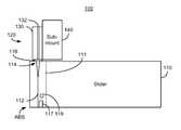
- the EAMR disk drive 100includes a slider 110 , a media (not shown) such as a disk and a laser assembly 120 .
- the laser assembly 120is separated from the slider by a certain distance.
- the laser assembly 120has been affixed to the slider 110 .
- the laser assembly 120includes a laser diode 130 and a laser sub-mount 140 .
- the laser diode 130includes a laser cavity 132 and emission exit 134 .
- Laser lightis generated in the laser cavity 132 and is output via the emission exit 134 .
- Emitted laser light 136is also shown.
- the submount 140may be used to provide mechanical stability for the laser diode 130 and to mount the laser diode 130 to the slider 120 . In another embodiment, the submount 140 may be omitted and/or another type of laser 130 used.
- the emitted laser light 136forms a laser spot 136 on the slider 110 .
- the slider 110includes an air-bearing surface (ABS), a laser input side 113 , an EAMR transducer 111 and an antireflective coating (ARC) layer 116 .
- the laser input side 113faces the laser 130 .
- the laser input side 113is opposite to the ABS.
- the laser input side 113could have another relationship to the ABS.
- the EAMR transducer 111includes a waveguide 112 , a write pole 117 and coil(s) 119 .
- the write pole 117 and coil(s) 119are simply shown as blocks in the EAMR transducer 111 .
- FIG. 4depicts a portion of the laser input side 113 of the slider 100 .
- the ARC layer 116is on the laser input side 113 and resides between the laser 130 and the input 114 of the waveguide 112 .
- the slider 110may optionally include alignment marks 118 used in aligning the slider 110 with the laser assembly 120 .
- the laser assembly 120may also include alignment marks (not shown) corresponding to the alignment marks 118 on the slider 110 .
- the laser lightforms a spot 136 on the laser input side 113 of the slider 110 .
- FIG. 5depicts a portion of the EAMR disk drive 100 that includes the waveguide 112 and the ARC layer 116 .
- the waveguide 112includes the input 114 as well as an output 115 .
- the waveguide 112thus directs laser light 136 from the input 114 to the ABS.
- a significant portion of the laser lightis coupled out to the media, for example using a near-field transducer (not shown).
- a portion of the lightis also directed to the output 115 .
- the light emitted from the output 115may be used in aligning the laser 130 to the waveguide input 114 as described below.
- the ARC layer 116resides between the laser 130 and the input 114 of the waveguide 112 .
- the ARC layer 116may include at least one of a MgF 2 layer, a Ta 2 O 5 layer, a SiO 2 layer and a Si 3 N 4 layer.
- the ARC layer 116is a single layer.
- the ARC layer 116is a multilayer.
- the total thickness of the ARC layer 116is generally one-fourth of the wavelength of the light emitted by the laser 130 .
- the ARC layer 116thus can reduce back reflections for the laser light 136 incident on the waveguide input 114 .
- the ARC layer 116also occupies only a portion of the laser input side 113 of the slider 110 .
- the area of the laser input side 113 occupied by the ARC layer 116is larger than the waveguide input 114 but significantly smaller than the total area of the laser input side 113 of the slider 110 .
- the portion of the laser input side 113 occupied by the ARC layer 116is larger than the laser spot size 136 .
- the ARC layer 116is at least twice the laser spot size 136 .
- the region of the laser input side 113 occupied by the ARC layer 116terminates within a laser spot diameter of the edges of the input 114 of the waveguide.
- the ARC layer 116has edges that are not more than one micron from the edges of the waveguide input 114 .
- the ARC layer 116is rectangular in shape. In some embodiments, the rectangle is least eight microns long and eight microns wide. In some such embodiments, the rectangle is least ten microns long and ten microns wide. However, in other embodiments, the ARC layer 116 may have another shape and/or another size. For example, the ARC layer 116 may be a square, an ellipse, a circle or have another shape. In some embodiments, the shape of the ARC layer 116 is substantially the same as the shape as the laser spot 116 .
- the ARC layer 116may facilitate alignment of the laser 130 and the waveguide 112 of the EAMR transducer 111 .
- the laser spot 136 from the lasermay be aligned with the ARC layer 116 .
- the ARC layer 116covers a small portion of the laser input side 113 of the slider 110 that includes the waveguide input 114 . Aligning the laser spot 136 with the ARC layer 116 thus performs a coarse alignment. A fine alignment may then be carried out, for example by monitoring the light at the waveguide output 115 . A maximum in the signal at the waveguide output 115 corresponds to the laser spot 136 being aligned with the waveguide input 114 .
- the laser assembly 120may then be affixed to the slider 110 . Such a situation is depicted in FIG. 6 .
- the EAMR disk drive 100may function as desired.
- the laser 130provides energy to the input 114 of the waveguide 112 in the form of laser light/the laser spot 136 .
- the waveguide 112directs the energy from the laser 130 to the ABS.
- the energyis directed to a near-field transducer (not shown).
- the energy from the laseris focused onto a region of the media (not shown), which is heated.
- the write pole 117is energized by the coils 119 and writes to the heated region of the media.
- the manufacturability, performance and reliability of the EAMR disk drive 100may be improved.
- Use of the ARC layer 116may reduce back reflections. Consequently, the laser 130 may be less subject to damage. Reliability of the EAMR disk drive 100 may thus be improved.
- the reduction in back reflectionsalso corresponds to a larger percentage of light from the laser 130 being coupled into the waveguide 112 . Thus, the coupling efficiency of the laser 130 may be improved. Performance of the laser 130 and, therefore, the EAMR disk drive 100 may thus be improved.
- the ARC layer 116may also be used in aligning the laser 130 to the waveguide input 114 . A coarse alignment may thus be more easily and rapidly performed. Consequently, fabrication of the EAMR disk drive 100 may be facilitated.
- FIG. 7is a diagram depicting a laser input side of an exemplary embodiment of a slider 110 ′ for an EAMR disk drive 100 ′.
- the EAMR disk drive 100 ′is analogous to the EAMR disk drive 100 .
- the EAMR disk drive 100 ′thus includes a slider 110 ′, EAMR transducer 111 ′, waveguide input 114 ′, waveguide output 115 ′, ARC layer 116 ′ and, optionally, alignment marks 118 ′ that correspond to the slider 110 , EAMR transducer 111 , waveguide input 114 , waveguide output 115 , ARC layer 116 and alignment marks 118 , respectively.
- the ARC layer 116 ′is on the laser input side 113 ′ and resides between the laser (not shown in FIG. 7 ) and the input 114 ′ of the waveguide 112 ′.
- the ARC layer 116 ′has an elliptical shape that corresponds to the shape of the laser spot 136 ′.
- the waveguide input 114 ′is not centered in the ARC layer 116 .
- the ARC layer 116still covers the waveguide input 114 ′.
- the waveguide input 114 ′is centered in the ARC layer 116 ′.
- the EAMR disk drive 100 ′shares the benefits of the EAMR disk drive 100 .
- the ARC layer 116 ′may reduce back reflections and facilitate alignment of the laser 130 ′ and waveguide input 114 ′.
- reliability, performance and manufacturability of the EAMR disk drive 100 ′may be improved.
- FIGS. 8-9depicting a laser input side of an exemplary embodiment of a slider 110 ′′ and a side view of an ARC layer 116 ′′ for an EAMR disk drive 100 ′′.
- FIGS. 8-9are not to scale.
- the EAMR disk drive 100 ′′is analogous to the EAMR disk drives 100 and 100 ′.
- the EAMR disk drive 100 ′′thus includes a slider 110 ′′, EAMR transducer 111 ′′, waveguide input 114 ′′, waveguide output 115 ′′, ARC layer 116 ′′ and, optionally, alignment marks 118 ′′ that correspond to the slider 110 / 110 ′, EAMR transducer 111 / 111 ′, waveguide input 114 / 114 ′, waveguide output 115 / 115 ′, ARC layer 116 / 116 ′ and alignment marks 118 / 118 ′, respectively.
- the ARC layer 116 ′′is on the laser input side 113 ′′ and resides between the laser (not shown in FIGS. 8-9 ) and the input 114 ′′ of the waveguide 112 ′′.
- the ARC layer 116 ′′includes two layers 116 A and 116 B. In another embodiment, additional layers may also be included.
- the ARC layer 116 ′′is thus a multilayer.
- Each of the layers 116 A and 116 Bmay be an MgF 2 layer, a Ta 2 O 5 layer, a SiO 2 layer and/or a Si 3 N 4 layer. In other embodiments, other antireflective materials and/or another number of layers may be used.
- the ARC layer 116 ′′may include four sublayers.
- the EAMR disk drive 100 ′′may share the benefits of the EAMR disk drives 100 and 100 ′.
- the ARC layer 116 ′′may reduce back reflections and facilitate alignment of the laser and waveguide input 114 ′′.
- reliability, coupling efficiency and fabrication of the EAMR disk drive 100 ′′may be improved.
- use of the multilayer ARC layer 116 ′may enhance the ability of the ARC layer 116 ′′ in reducing back reflections. Fluctuations in the coupling efficiency with distance between the laser and waveguide input 114 ′′ may also be reduced.
- performance and manufacturability of the EAMR disk drive 100 ′′may be further improved.
- FIG. 10is a flow chart depicting an exemplary embodiment of a method 200 for aligning a laser with a waveguide in fabrication of an EAMR head. For simplicity, only some steps are shown. Further, the steps may include one or more substeps. Steps may also be combined, interleaved, and/or performed in another order.
- the method 200is described in the context of fabricating the EAMR disk drive 100 of FIGS. 3-6 . However, the method 200 may be used to form another device including but not limited to the EAMR disk drives 100 ′ and 100 ′′.
- the method 200may start after the alignment marks 118 have been used to roughly align the laser 130 to the ARC layer 116 .
- the laser spot 136may still be far from the waveguide input 114 .
- the laser spot 136may overlap the ARC layer 116 .
- the use of alignment marksmay be omitted.
- Step 202may include monitoring back reflections for the laser 130 . As the alignment between the laser spot 136 and the ARC layer 116 is improved, back reflections are reduced. A minimum in the back reflections may correspond to the laser 130 being aligned with the ARC layer 116 . Thus, the laser spot 136 completely overlaps the ARC layer 116 . In embodiments in which the ARC layer 116 extends less than the laser spot diameter from the waveguide input 114 , step 202 also ensures that the laser spot at least partially overlaps the waveguide input 114 . Thus, a coarse alignment has been performed in step 202 .
- Step 204may include monitoring the energy output by the waveguide output 115 . A maximum in this energy corresponds to the laser spot 136 being aligned with the waveguide input 114 . Thus, step 204 performs a fine alignment and may determine the final position of the laser 130 /laser spot 136 with respect to the waveguide input 114 .
- Step 206includes bonding the laser assembly 120 to the slider 110 , for example the laser assembly 120 may be epoxied to the slider 110 .
- the slider 110 and laser assembly 120are heated to reflow solder pads (not shown). Mechanical and electrical connection is made between the laser 120 and slider 110 .
- fabrication of the EAMR disk drivemay be completed.
- the method 200alignment of the laser 130 to the waveguide 112 may be facilitated.
- the laser spot 136may be more quickly and easily brought to a position that is close to the desired alignment with the waveguide input 114 .
- use of the ARC layer 116may also reduce back reflections. Consequently, manufacturability, reliability, and performance of the EAMR disk drive 100 / 100 ′/ 100 ′′ may be improved.
Landscapes
- Optical Head (AREA)
- Recording Or Reproducing By Magnetic Means (AREA)
Abstract
Description
Claims (20)
Priority Applications (2)
| Application Number | Priority Date | Filing Date | Title |
|---|---|---|---|
| US13/631,641US8681594B1 (en) | 2012-09-28 | 2012-09-28 | Method and system for improving laser alignment and optical transmission efficiency of an energy assisted magnetic recording head |
| CN201310455119.3ACN103714829B (en) | 2012-09-28 | 2013-09-29 | The system and method for improving the laser alignment and optical delivery efficiency of energy assisted magnetic recording head |
Applications Claiming Priority (1)
| Application Number | Priority Date | Filing Date | Title |
|---|---|---|---|
| US13/631,641US8681594B1 (en) | 2012-09-28 | 2012-09-28 | Method and system for improving laser alignment and optical transmission efficiency of an energy assisted magnetic recording head |
Publications (2)
| Publication Number | Publication Date |
|---|---|
| US8681594B1true US8681594B1 (en) | 2014-03-25 |
| US20140092715A1 US20140092715A1 (en) | 2014-04-03 |
Family
ID=50288877
Family Applications (1)
| Application Number | Title | Priority Date | Filing Date |
|---|---|---|---|
| US13/631,641ActiveUS8681594B1 (en) | 2012-09-28 | 2012-09-28 | Method and system for improving laser alignment and optical transmission efficiency of an energy assisted magnetic recording head |
Country Status (2)
| Country | Link |
|---|---|
| US (1) | US8681594B1 (en) |
| CN (1) | CN103714829B (en) |
Cited By (138)
| Publication number | Priority date | Publication date | Assignee | Title |
|---|---|---|---|---|
| US20130279310A1 (en)* | 2012-04-24 | 2013-10-24 | Seagate Technology Llc | Antireflection coating for slider |
| US8830628B1 (en) | 2009-02-23 | 2014-09-09 | Western Digital (Fremont), Llc | Method and system for providing a perpendicular magnetic recording head |
| US8879207B1 (en) | 2011-12-20 | 2014-11-04 | Western Digital (Fremont), Llc | Method for providing a side shield for a magnetic recording transducer using an air bridge |
| US8883017B1 (en) | 2013-03-12 | 2014-11-11 | Western Digital (Fremont), Llc | Method and system for providing a read transducer having seamless interfaces |
| US8917581B1 (en) | 2013-12-18 | 2014-12-23 | Western Digital Technologies, Inc. | Self-anneal process for a near field transducer and chimney in a hard disk drive assembly |
| US8923102B1 (en) | 2013-07-16 | 2014-12-30 | Western Digital (Fremont), Llc | Optical grating coupling for interferometric waveguides in heat assisted magnetic recording heads |
| US8947985B1 (en) | 2013-07-16 | 2015-02-03 | Western Digital (Fremont), Llc | Heat assisted magnetic recording transducers having a recessed pole |
| US8953422B1 (en) | 2014-06-10 | 2015-02-10 | Western Digital (Fremont), Llc | Near field transducer using dielectric waveguide core with fine ridge feature |
| US8958272B1 (en) | 2014-06-10 | 2015-02-17 | Western Digital (Fremont), Llc | Interfering near field transducer for energy assisted magnetic recording |
| US8970988B1 (en) | 2013-12-31 | 2015-03-03 | Western Digital (Fremont), Llc | Electric gaps and method for making electric gaps for multiple sensor arrays |
| US8971160B1 (en) | 2013-12-19 | 2015-03-03 | Western Digital (Fremont), Llc | Near field transducer with high refractive index pin for heat assisted magnetic recording |
| US8976635B1 (en) | 2014-06-10 | 2015-03-10 | Western Digital (Fremont), Llc | Near field transducer driven by a transverse electric waveguide for energy assisted magnetic recording |
| US8982508B1 (en) | 2011-10-31 | 2015-03-17 | Western Digital (Fremont), Llc | Method for providing a side shield for a magnetic recording transducer |
| US8980109B1 (en) | 2012-12-11 | 2015-03-17 | Western Digital (Fremont), Llc | Method for providing a magnetic recording transducer using a combined main pole and side shield CMP for a wraparound shield scheme |
| US8984740B1 (en) | 2012-11-30 | 2015-03-24 | Western Digital (Fremont), Llc | Process for providing a magnetic recording transducer having a smooth magnetic seed layer |
| US8988825B1 (en) | 2014-02-28 | 2015-03-24 | Western Digital (Fremont, LLC | Method for fabricating a magnetic writer having half-side shields |
| US8988812B1 (en) | 2013-11-27 | 2015-03-24 | Western Digital (Fremont), Llc | Multi-sensor array configuration for a two-dimensional magnetic recording (TDMR) operation |
| US8993217B1 (en) | 2013-04-04 | 2015-03-31 | Western Digital (Fremont), Llc | Double exposure technique for high resolution disk imaging |
| US8995087B1 (en) | 2006-11-29 | 2015-03-31 | Western Digital (Fremont), Llc | Perpendicular magnetic recording write head having a wrap around shield |
| US8997832B1 (en) | 2010-11-23 | 2015-04-07 | Western Digital (Fremont), Llc | Method of fabricating micrometer scale components |
| US9001628B1 (en) | 2013-12-16 | 2015-04-07 | Western Digital (Fremont), Llc | Assistant waveguides for evaluating main waveguide coupling efficiency and diode laser alignment tolerances for hard disk |
| US9001467B1 (en) | 2014-03-05 | 2015-04-07 | Western Digital (Fremont), Llc | Method for fabricating side shields in a magnetic writer |
| US9007719B1 (en) | 2013-10-23 | 2015-04-14 | Western Digital (Fremont), Llc | Systems and methods for using double mask techniques to achieve very small features |
| US9007725B1 (en) | 2014-10-07 | 2015-04-14 | Western Digital (Fremont), Llc | Sensor with positive coupling between dual ferromagnetic free layer laminates |
| US9007879B1 (en) | 2014-06-10 | 2015-04-14 | Western Digital (Fremont), Llc | Interfering near field transducer having a wide metal bar feature for energy assisted magnetic recording |
| US9013836B1 (en) | 2013-04-02 | 2015-04-21 | Western Digital (Fremont), Llc | Method and system for providing an antiferromagnetically coupled return pole |
| US9018737B2 (en)* | 2013-03-06 | 2015-04-28 | Seagate Technology Llc | Submount assembly integration |
| US9025423B1 (en)* | 2014-07-14 | 2015-05-05 | HGST Netherlands B.V. | Thermally conductive features for a heat-assisted magnetic recording head |
| US9042058B1 (en) | 2013-10-17 | 2015-05-26 | Western Digital Technologies, Inc. | Shield designed for middle shields in a multiple sensor array |
| US9042052B1 (en) | 2014-06-23 | 2015-05-26 | Western Digital (Fremont), Llc | Magnetic writer having a partially shunted coil |
| US9042208B1 (en) | 2013-03-11 | 2015-05-26 | Western Digital Technologies, Inc. | Disk drive measuring fly height by applying a bias voltage to an electrically insulated write component of a head |
| US9042057B1 (en) | 2013-01-09 | 2015-05-26 | Western Digital (Fremont), Llc | Methods for providing magnetic storage elements with high magneto-resistance using Heusler alloys |
| US9042051B2 (en) | 2013-08-15 | 2015-05-26 | Western Digital (Fremont), Llc | Gradient write gap for perpendicular magnetic recording writer |
| US9053735B1 (en) | 2014-06-20 | 2015-06-09 | Western Digital (Fremont), Llc | Method for fabricating a magnetic writer using a full-film metal planarization |
| US9064507B1 (en) | 2009-07-31 | 2015-06-23 | Western Digital (Fremont), Llc | Magnetic etch-stop layer for magnetoresistive read heads |
| US9065043B1 (en) | 2012-06-29 | 2015-06-23 | Western Digital (Fremont), Llc | Tunnel magnetoresistance read head with narrow shield-to-shield spacing |
| US9064527B1 (en) | 2013-04-12 | 2015-06-23 | Western Digital (Fremont), Llc | High order tapered waveguide for use in a heat assisted magnetic recording head |
| US9064528B1 (en) | 2013-05-17 | 2015-06-23 | Western Digital Technologies, Inc. | Interferometric waveguide usable in shingled heat assisted magnetic recording in the absence of a near-field transducer |
| US9070381B1 (en) | 2013-04-12 | 2015-06-30 | Western Digital (Fremont), Llc | Magnetic recording read transducer having a laminated free layer |
| US9082423B1 (en) | 2013-12-18 | 2015-07-14 | Western Digital (Fremont), Llc | Magnetic recording write transducer having an improved trailing surface profile |
| US9087527B1 (en) | 2014-10-28 | 2015-07-21 | Western Digital (Fremont), Llc | Apparatus and method for middle shield connection in magnetic recording transducers |
| US9087534B1 (en) | 2011-12-20 | 2015-07-21 | Western Digital (Fremont), Llc | Method and system for providing a read transducer having soft and hard magnetic bias structures |
| US9093639B2 (en) | 2012-02-21 | 2015-07-28 | Western Digital (Fremont), Llc | Methods for manufacturing a magnetoresistive structure utilizing heating and cooling |
| US9104107B1 (en) | 2013-04-03 | 2015-08-11 | Western Digital (Fremont), Llc | DUV photoresist process |
| US9111564B1 (en) | 2013-04-02 | 2015-08-18 | Western Digital (Fremont), Llc | Magnetic recording writer having a main pole with multiple flare angles |
| US9111558B1 (en) | 2014-03-14 | 2015-08-18 | Western Digital (Fremont), Llc | System and method of diffractive focusing of light in a waveguide |
| US9111550B1 (en) | 2014-12-04 | 2015-08-18 | Western Digital (Fremont), Llc | Write transducer having a magnetic buffer layer spaced between a side shield and a write pole by non-magnetic layers |
| US9123359B1 (en) | 2010-12-22 | 2015-09-01 | Western Digital (Fremont), Llc | Magnetic recording transducer with sputtered antiferromagnetic coupling trilayer between plated ferromagnetic shields and method of fabrication |
| US9123362B1 (en) | 2011-03-22 | 2015-09-01 | Western Digital (Fremont), Llc | Methods for assembling an electrically assisted magnetic recording (EAMR) head |
| US9123358B1 (en) | 2012-06-11 | 2015-09-01 | Western Digital (Fremont), Llc | Conformal high moment side shield seed layer for perpendicular magnetic recording writer |
| US9123374B1 (en) | 2015-02-12 | 2015-09-01 | Western Digital (Fremont), Llc | Heat assisted magnetic recording writer having an integrated polarization rotation plate |
| US9135937B1 (en) | 2014-05-09 | 2015-09-15 | Western Digital (Fremont), Llc | Current modulation on laser diode for energy assisted magnetic recording transducer |
| US9135930B1 (en) | 2014-03-06 | 2015-09-15 | Western Digital (Fremont), Llc | Method for fabricating a magnetic write pole using vacuum deposition |
| US9142233B1 (en) | 2014-02-28 | 2015-09-22 | Western Digital (Fremont), Llc | Heat assisted magnetic recording writer having a recessed pole |
| US9147404B1 (en) | 2015-03-31 | 2015-09-29 | Western Digital (Fremont), Llc | Method and system for providing a read transducer having a dual free layer |
| US9147408B1 (en) | 2013-12-19 | 2015-09-29 | Western Digital (Fremont), Llc | Heated AFM layer deposition and cooling process for TMR magnetic recording sensor with high pinning field |
| US9153255B1 (en) | 2014-03-05 | 2015-10-06 | Western Digital (Fremont), Llc | Method for fabricating a magnetic writer having an asymmetric gap and shields |
| US9183854B2 (en) | 2014-02-24 | 2015-11-10 | Western Digital (Fremont), Llc | Method to make interferometric taper waveguide for HAMR light delivery |
| US9190085B1 (en) | 2014-03-12 | 2015-11-17 | Western Digital (Fremont), Llc | Waveguide with reflective grating for localized energy intensity |
| US9190079B1 (en) | 2014-09-22 | 2015-11-17 | Western Digital (Fremont), Llc | Magnetic write pole having engineered radius of curvature and chisel angle profiles |
| US9194692B1 (en) | 2013-12-06 | 2015-11-24 | Western Digital (Fremont), Llc | Systems and methods for using white light interferometry to measure undercut of a bi-layer structure |
| US9202480B2 (en) | 2009-10-14 | 2015-12-01 | Western Digital (Fremont), LLC. | Double patterning hard mask for damascene perpendicular magnetic recording (PMR) writer |
| US9202493B1 (en) | 2014-02-28 | 2015-12-01 | Western Digital (Fremont), Llc | Method of making an ultra-sharp tip mode converter for a HAMR head |
| US9213322B1 (en) | 2012-08-16 | 2015-12-15 | Western Digital (Fremont), Llc | Methods for providing run to run process control using a dynamic tuner |
| US9214172B2 (en) | 2013-10-23 | 2015-12-15 | Western Digital (Fremont), Llc | Method of manufacturing a magnetic read head |
| US9214169B1 (en) | 2014-06-20 | 2015-12-15 | Western Digital (Fremont), Llc | Magnetic recording read transducer having a laminated free layer |
| US9214165B1 (en) | 2014-12-18 | 2015-12-15 | Western Digital (Fremont), Llc | Magnetic writer having a gradient in saturation magnetization of the shields |
| US20150364899A1 (en)* | 2014-06-12 | 2015-12-17 | Seagate Technology Llc | Bragg grating external cavity laser |
| US9230565B1 (en) | 2014-06-24 | 2016-01-05 | Western Digital (Fremont), Llc | Magnetic shield for magnetic recording head |
| US9236560B1 (en) | 2014-12-08 | 2016-01-12 | Western Digital (Fremont), Llc | Spin transfer torque tunneling magnetoresistive device having a laminated free layer with perpendicular magnetic anisotropy |
| US9245545B1 (en) | 2013-04-12 | 2016-01-26 | Wester Digital (Fremont), Llc | Short yoke length coils for magnetic heads in disk drives |
| US9245562B1 (en) | 2015-03-30 | 2016-01-26 | Western Digital (Fremont), Llc | Magnetic recording writer with a composite main pole |
| US9245543B1 (en) | 2010-06-25 | 2016-01-26 | Western Digital (Fremont), Llc | Method for providing an energy assisted magnetic recording head having a laser integrally mounted to the slider |
| US9251813B1 (en) | 2009-04-19 | 2016-02-02 | Western Digital (Fremont), Llc | Method of making a magnetic recording head |
| US9263067B1 (en) | 2013-05-29 | 2016-02-16 | Western Digital (Fremont), Llc | Process for making PMR writer with constant side wall angle |
| US9263071B1 (en) | 2015-03-31 | 2016-02-16 | Western Digital (Fremont), Llc | Flat NFT for heat assisted magnetic recording |
| US9269382B1 (en) | 2012-06-29 | 2016-02-23 | Western Digital (Fremont), Llc | Method and system for providing a read transducer having improved pinning of the pinned layer at higher recording densities |
| US9275657B1 (en) | 2013-08-14 | 2016-03-01 | Western Digital (Fremont), Llc | Process for making PMR writer with non-conformal side gaps |
| US9280990B1 (en) | 2013-12-11 | 2016-03-08 | Western Digital (Fremont), Llc | Method for fabricating a magnetic writer using multiple etches |
| US9286919B1 (en) | 2014-12-17 | 2016-03-15 | Western Digital (Fremont), Llc | Magnetic writer having a dual side gap |
| US9287494B1 (en) | 2013-06-28 | 2016-03-15 | Western Digital (Fremont), Llc | Magnetic tunnel junction (MTJ) with a magnesium oxide tunnel barrier |
| US9305583B1 (en) | 2014-02-18 | 2016-04-05 | Western Digital (Fremont), Llc | Method for fabricating a magnetic writer using multiple etches of damascene materials |
| US9312064B1 (en) | 2015-03-02 | 2016-04-12 | Western Digital (Fremont), Llc | Method to fabricate a magnetic head including ion milling of read gap using dual layer hard mask |
| US9318130B1 (en) | 2013-07-02 | 2016-04-19 | Western Digital (Fremont), Llc | Method to fabricate tunneling magnetic recording heads with extended pinned layer |
| US9336814B1 (en) | 2013-03-12 | 2016-05-10 | Western Digital (Fremont), Llc | Inverse tapered waveguide for use in a heat assisted magnetic recording head |
| US9343087B1 (en) | 2014-12-21 | 2016-05-17 | Western Digital (Fremont), Llc | Method for fabricating a magnetic writer having half shields |
| US9343086B1 (en) | 2013-09-11 | 2016-05-17 | Western Digital (Fremont), Llc | Magnetic recording write transducer having an improved sidewall angle profile |
| US9343098B1 (en) | 2013-08-23 | 2016-05-17 | Western Digital (Fremont), Llc | Method for providing a heat assisted magnetic recording transducer having protective pads |
| US9349394B1 (en) | 2013-10-18 | 2016-05-24 | Western Digital (Fremont), Llc | Method for fabricating a magnetic writer having a gradient side gap |
| US9349392B1 (en) | 2012-05-24 | 2016-05-24 | Western Digital (Fremont), Llc | Methods for improving adhesion on dielectric substrates |
| US9361914B1 (en) | 2014-06-18 | 2016-06-07 | Western Digital (Fremont), Llc | Magnetic sensor with thin capping layer |
| US9361913B1 (en) | 2013-06-03 | 2016-06-07 | Western Digital (Fremont), Llc | Recording read heads with a multi-layer AFM layer methods and apparatuses |
| US9368134B1 (en) | 2010-12-16 | 2016-06-14 | Western Digital (Fremont), Llc | Method and system for providing an antiferromagnetically coupled writer |
| US9384765B1 (en) | 2015-09-24 | 2016-07-05 | Western Digital (Fremont), Llc | Method and system for providing a HAMR writer having improved optical efficiency |
| US9384763B1 (en) | 2015-03-26 | 2016-07-05 | Western Digital (Fremont), Llc | Dual free layer magnetic reader having a rear bias structure including a soft bias layer |
| US9396743B1 (en) | 2014-02-28 | 2016-07-19 | Western Digital (Fremont), Llc | Systems and methods for controlling soft bias thickness for tunnel magnetoresistance readers |
| US9396742B1 (en) | 2012-11-30 | 2016-07-19 | Western Digital (Fremont), Llc | Magnetoresistive sensor for a magnetic storage system read head, and fabrication method thereof |
| US9406331B1 (en) | 2013-06-17 | 2016-08-02 | Western Digital (Fremont), Llc | Method for making ultra-narrow read sensor and read transducer device resulting therefrom |
| US9424866B1 (en) | 2015-09-24 | 2016-08-23 | Western Digital (Fremont), Llc | Heat assisted magnetic recording write apparatus having a dielectric gap |
| US9431038B1 (en) | 2015-06-29 | 2016-08-30 | Western Digital (Fremont), Llc | Method for fabricating a magnetic write pole having an improved sidewall angle profile |
| US9431031B1 (en) | 2015-03-24 | 2016-08-30 | Western Digital (Fremont), Llc | System and method for magnetic transducers having multiple sensors and AFC shields |
| US9431032B1 (en) | 2013-08-14 | 2016-08-30 | Western Digital (Fremont), Llc | Electrical connection arrangement for a multiple sensor array usable in two-dimensional magnetic recording |
| US9431039B1 (en) | 2013-05-21 | 2016-08-30 | Western Digital (Fremont), Llc | Multiple sensor array usable in two-dimensional magnetic recording |
| US9431047B1 (en) | 2013-05-01 | 2016-08-30 | Western Digital (Fremont), Llc | Method for providing an improved AFM reader shield |
| US9437251B1 (en) | 2014-12-22 | 2016-09-06 | Western Digital (Fremont), Llc | Apparatus and method having TDMR reader to reader shunts |
| US9443541B1 (en) | 2015-03-24 | 2016-09-13 | Western Digital (Fremont), Llc | Magnetic writer having a gradient in saturation magnetization of the shields and return pole |
| US9441938B1 (en) | 2013-10-08 | 2016-09-13 | Western Digital (Fremont), Llc | Test structures for measuring near field transducer disc length |
| US9449621B1 (en) | 2015-03-26 | 2016-09-20 | Western Digital (Fremont), Llc | Dual free layer magnetic reader having a rear bias structure having a high aspect ratio |
| US9449625B1 (en) | 2014-12-24 | 2016-09-20 | Western Digital (Fremont), Llc | Heat assisted magnetic recording head having a plurality of diffusion barrier layers |
| US9472216B1 (en) | 2015-09-23 | 2016-10-18 | Western Digital (Fremont), Llc | Differential dual free layer magnetic reader |
| US20160314810A1 (en)* | 2014-10-01 | 2016-10-27 | Seagate Technology Llc | Writer pole formation |
| US9484051B1 (en) | 2015-11-09 | 2016-11-01 | The Provost, Fellows, Foundation Scholars and the other members of Board, of the College of the Holy and Undivided Trinity of Queen Elizabeth near Dublin | Method and system for reducing undesirable reflections in a HAMR write apparatus |
| US9508365B1 (en) | 2015-06-24 | 2016-11-29 | Western Digital (Fremont), LLC. | Magnetic reader having a crystal decoupling structure |
| US9508372B1 (en) | 2015-06-03 | 2016-11-29 | Western Digital (Fremont), Llc | Shingle magnetic writer having a low sidewall angle pole |
| US9508363B1 (en) | 2014-06-17 | 2016-11-29 | Western Digital (Fremont), Llc | Method for fabricating a magnetic write pole having a leading edge bevel |
| US9530443B1 (en) | 2015-06-25 | 2016-12-27 | Western Digital (Fremont), Llc | Method for fabricating a magnetic recording device having a high aspect ratio structure |
| US9564150B1 (en) | 2015-11-24 | 2017-02-07 | Western Digital (Fremont), Llc | Magnetic read apparatus having an improved read sensor isolation circuit |
| US9595273B1 (en) | 2015-09-30 | 2017-03-14 | Western Digital (Fremont), Llc | Shingle magnetic writer having nonconformal shields |
| US9646639B2 (en) | 2015-06-26 | 2017-05-09 | Western Digital (Fremont), Llc | Heat assisted magnetic recording writer having integrated polarization rotation waveguides |
| US9666214B1 (en) | 2015-09-23 | 2017-05-30 | Western Digital (Fremont), Llc | Free layer magnetic reader that may have a reduced shield-to-shield spacing |
| US9666218B1 (en)* | 2016-07-28 | 2017-05-30 | Sae Magnetics (H.K.) Ltd. | Thermal assisted magnetic head provided with light detector that detects reflected light |
| US9721595B1 (en) | 2014-12-04 | 2017-08-01 | Western Digital (Fremont), Llc | Method for providing a storage device |
| US9740805B1 (en) | 2015-12-01 | 2017-08-22 | Western Digital (Fremont), Llc | Method and system for detecting hotspots for photolithographically-defined devices |
| US9741366B1 (en) | 2014-12-18 | 2017-08-22 | Western Digital (Fremont), Llc | Method for fabricating a magnetic writer having a gradient in saturation magnetization of the shields |
| US9754611B1 (en) | 2015-11-30 | 2017-09-05 | Western Digital (Fremont), Llc | Magnetic recording write apparatus having a stepped conformal trailing shield |
| US9767831B1 (en) | 2015-12-01 | 2017-09-19 | Western Digital (Fremont), Llc | Magnetic writer having convex trailing surface pole and conformal write gap |
| US9786301B1 (en) | 2014-12-02 | 2017-10-10 | Western Digital (Fremont), Llc | Apparatuses and methods for providing thin shields in a multiple sensor array |
| US9799351B1 (en) | 2015-11-30 | 2017-10-24 | Western Digital (Fremont), Llc | Short yoke length writer having assist coils |
| US9812155B1 (en) | 2015-11-23 | 2017-11-07 | Western Digital (Fremont), Llc | Method and system for fabricating high junction angle read sensors |
| US9842615B1 (en) | 2015-06-26 | 2017-12-12 | Western Digital (Fremont), Llc | Magnetic reader having a nonmagnetic insertion layer for the pinning layer |
| US9858951B1 (en) | 2015-12-01 | 2018-01-02 | Western Digital (Fremont), Llc | Method for providing a multilayer AFM layer in a read sensor |
| US9881638B1 (en) | 2014-12-17 | 2018-01-30 | Western Digital (Fremont), Llc | Method for providing a near-field transducer (NFT) for a heat assisted magnetic recording (HAMR) device |
| US9934811B1 (en) | 2014-03-07 | 2018-04-03 | Western Digital (Fremont), Llc | Methods for controlling stray fields of magnetic features using magneto-elastic anisotropy |
| US9953670B1 (en) | 2015-11-10 | 2018-04-24 | Western Digital (Fremont), Llc | Method and system for providing a HAMR writer including a multi-mode interference device |
| US10037770B1 (en) | 2015-11-12 | 2018-07-31 | Western Digital (Fremont), Llc | Method for providing a magnetic recording write apparatus having a seamless pole |
| US10074387B1 (en) | 2014-12-21 | 2018-09-11 | Western Digital (Fremont), Llc | Method and system for providing a read transducer having symmetric antiferromagnetically coupled shields |
| US10614841B1 (en)* | 2018-11-30 | 2020-04-07 | Sae Magnetics (H.K.) Ltd. | Thermally assisted magnetic head, method for reducing reflected light, head gimbal assembly, and hard disk drive |
| US20250104732A1 (en)* | 2023-09-26 | 2025-03-27 | Western Digital Technologies, Inc. | Hard disk drive slider coating for suspension mechanical improvement |
Families Citing this family (1)
| Publication number | Priority date | Publication date | Assignee | Title |
|---|---|---|---|---|
| US9558775B2 (en)* | 2015-02-19 | 2017-01-31 | Seagate Technology Llc | Laser diode submount/slider interface with reduced thermal resistance |
Citations (9)
| Publication number | Priority date | Publication date | Assignee | Title |
|---|---|---|---|---|
| US20030179426A1 (en) | 2002-01-31 | 2003-09-25 | Citizen Watch Co., Ltd. | Optical deflection apparatus and optical deflection method |
| US6694076B2 (en) | 2001-03-30 | 2004-02-17 | Intel Corporation | Method for centering a core of a waveguide amplifier |
| US6873638B2 (en) | 2001-06-29 | 2005-03-29 | 3M Innovative Properties Company | Laser diode chip with waveguide |
| US7184625B2 (en) | 2003-02-11 | 2007-02-27 | Luxtera, Inc | Optical waveguide grating coupler incorporating reflective optical elements and anti-reflection elements |
| US7483229B2 (en) | 2004-12-08 | 2009-01-27 | Seagate Technology Llc | Optical coupling to data recording transducer |
| US20110090770A1 (en)* | 2009-10-15 | 2011-04-21 | Hitachi, Ltd. | Thermal-assisted-magnetic-recording head and magnetic recording system using the thermal-assisted-magnetic-recoring head |
| US20110216635A1 (en) | 2010-03-05 | 2011-09-08 | Hitachi, Ltd. | Head for thermal assisted magnetic recording device, and thermal assisted magnetic recording device |
| US20120051195A1 (en)* | 2010-08-30 | 2012-03-01 | Hitachi, Ltd. | Thermally-assisted recording head and magnetic recording system |
| US20120201491A1 (en)* | 2011-02-03 | 2012-08-09 | Seagate Technology Llc | Grating Assisted Surface Emitter Laser Coupling For Heat Assisted Magnetic Recording |
Family Cites Families (1)
| Publication number | Priority date | Publication date | Assignee | Title |
|---|---|---|---|---|
| US8593914B2 (en)* | 2010-12-22 | 2013-11-26 | Western Digital (Fremont), Llc | Method and system for optically coupling a laser with a transducer in an energy assisted magnetic recording disk drive |
- 2012
- 2012-09-28USUS13/631,641patent/US8681594B1/enactiveActive
- 2013
- 2013-09-29CNCN201310455119.3Apatent/CN103714829B/enactiveActive
Patent Citations (9)
| Publication number | Priority date | Publication date | Assignee | Title |
|---|---|---|---|---|
| US6694076B2 (en) | 2001-03-30 | 2004-02-17 | Intel Corporation | Method for centering a core of a waveguide amplifier |
| US6873638B2 (en) | 2001-06-29 | 2005-03-29 | 3M Innovative Properties Company | Laser diode chip with waveguide |
| US20030179426A1 (en) | 2002-01-31 | 2003-09-25 | Citizen Watch Co., Ltd. | Optical deflection apparatus and optical deflection method |
| US7184625B2 (en) | 2003-02-11 | 2007-02-27 | Luxtera, Inc | Optical waveguide grating coupler incorporating reflective optical elements and anti-reflection elements |
| US7483229B2 (en) | 2004-12-08 | 2009-01-27 | Seagate Technology Llc | Optical coupling to data recording transducer |
| US20110090770A1 (en)* | 2009-10-15 | 2011-04-21 | Hitachi, Ltd. | Thermal-assisted-magnetic-recording head and magnetic recording system using the thermal-assisted-magnetic-recoring head |
| US20110216635A1 (en) | 2010-03-05 | 2011-09-08 | Hitachi, Ltd. | Head for thermal assisted magnetic recording device, and thermal assisted magnetic recording device |
| US20120051195A1 (en)* | 2010-08-30 | 2012-03-01 | Hitachi, Ltd. | Thermally-assisted recording head and magnetic recording system |
| US20120201491A1 (en)* | 2011-02-03 | 2012-08-09 | Seagate Technology Llc | Grating Assisted Surface Emitter Laser Coupling For Heat Assisted Magnetic Recording |
Cited By (160)
| Publication number | Priority date | Publication date | Assignee | Title |
|---|---|---|---|---|
| US8995087B1 (en) | 2006-11-29 | 2015-03-31 | Western Digital (Fremont), Llc | Perpendicular magnetic recording write head having a wrap around shield |
| US8830628B1 (en) | 2009-02-23 | 2014-09-09 | Western Digital (Fremont), Llc | Method and system for providing a perpendicular magnetic recording head |
| US9251813B1 (en) | 2009-04-19 | 2016-02-02 | Western Digital (Fremont), Llc | Method of making a magnetic recording head |
| US9064507B1 (en) | 2009-07-31 | 2015-06-23 | Western Digital (Fremont), Llc | Magnetic etch-stop layer for magnetoresistive read heads |
| US9202480B2 (en) | 2009-10-14 | 2015-12-01 | Western Digital (Fremont), LLC. | Double patterning hard mask for damascene perpendicular magnetic recording (PMR) writer |
| US9245543B1 (en) | 2010-06-25 | 2016-01-26 | Western Digital (Fremont), Llc | Method for providing an energy assisted magnetic recording head having a laser integrally mounted to the slider |
| US8997832B1 (en) | 2010-11-23 | 2015-04-07 | Western Digital (Fremont), Llc | Method of fabricating micrometer scale components |
| US9672847B2 (en) | 2010-11-23 | 2017-06-06 | Western Digital (Fremont), Llc | Micrometer scale components |
| US9159345B1 (en) | 2010-11-23 | 2015-10-13 | Western Digital (Fremont), Llc | Micrometer scale components |
| US9368134B1 (en) | 2010-12-16 | 2016-06-14 | Western Digital (Fremont), Llc | Method and system for providing an antiferromagnetically coupled writer |
| US9123359B1 (en) | 2010-12-22 | 2015-09-01 | Western Digital (Fremont), Llc | Magnetic recording transducer with sputtered antiferromagnetic coupling trilayer between plated ferromagnetic shields and method of fabrication |
| US9123362B1 (en) | 2011-03-22 | 2015-09-01 | Western Digital (Fremont), Llc | Methods for assembling an electrically assisted magnetic recording (EAMR) head |
| US8982508B1 (en) | 2011-10-31 | 2015-03-17 | Western Digital (Fremont), Llc | Method for providing a side shield for a magnetic recording transducer |
| US9087534B1 (en) | 2011-12-20 | 2015-07-21 | Western Digital (Fremont), Llc | Method and system for providing a read transducer having soft and hard magnetic bias structures |
| US8879207B1 (en) | 2011-12-20 | 2014-11-04 | Western Digital (Fremont), Llc | Method for providing a side shield for a magnetic recording transducer using an air bridge |
| US9093639B2 (en) | 2012-02-21 | 2015-07-28 | Western Digital (Fremont), Llc | Methods for manufacturing a magnetoresistive structure utilizing heating and cooling |
| US20130279310A1 (en)* | 2012-04-24 | 2013-10-24 | Seagate Technology Llc | Antireflection coating for slider |
| US9940950B2 (en) | 2012-05-24 | 2018-04-10 | Western Digital (Fremont), Llc | Methods for improving adhesion on dielectric substrates |
| US9349392B1 (en) | 2012-05-24 | 2016-05-24 | Western Digital (Fremont), Llc | Methods for improving adhesion on dielectric substrates |
| US9123358B1 (en) | 2012-06-11 | 2015-09-01 | Western Digital (Fremont), Llc | Conformal high moment side shield seed layer for perpendicular magnetic recording writer |
| US9269382B1 (en) | 2012-06-29 | 2016-02-23 | Western Digital (Fremont), Llc | Method and system for providing a read transducer having improved pinning of the pinned layer at higher recording densities |
| US9412400B2 (en) | 2012-06-29 | 2016-08-09 | Western Digital (Fremont), Llc | Tunnel magnetoresistance read head with narrow shield-to-shield spacing |
| US9065043B1 (en) | 2012-06-29 | 2015-06-23 | Western Digital (Fremont), Llc | Tunnel magnetoresistance read head with narrow shield-to-shield spacing |
| US9213322B1 (en) | 2012-08-16 | 2015-12-15 | Western Digital (Fremont), Llc | Methods for providing run to run process control using a dynamic tuner |
| US8984740B1 (en) | 2012-11-30 | 2015-03-24 | Western Digital (Fremont), Llc | Process for providing a magnetic recording transducer having a smooth magnetic seed layer |
| US9396742B1 (en) | 2012-11-30 | 2016-07-19 | Western Digital (Fremont), Llc | Magnetoresistive sensor for a magnetic storage system read head, and fabrication method thereof |
| US8980109B1 (en) | 2012-12-11 | 2015-03-17 | Western Digital (Fremont), Llc | Method for providing a magnetic recording transducer using a combined main pole and side shield CMP for a wraparound shield scheme |
| US9042057B1 (en) | 2013-01-09 | 2015-05-26 | Western Digital (Fremont), Llc | Methods for providing magnetic storage elements with high magneto-resistance using Heusler alloys |
| US9018737B2 (en)* | 2013-03-06 | 2015-04-28 | Seagate Technology Llc | Submount assembly integration |
| US9042208B1 (en) | 2013-03-11 | 2015-05-26 | Western Digital Technologies, Inc. | Disk drive measuring fly height by applying a bias voltage to an electrically insulated write component of a head |
| US9336814B1 (en) | 2013-03-12 | 2016-05-10 | Western Digital (Fremont), Llc | Inverse tapered waveguide for use in a heat assisted magnetic recording head |
| US8883017B1 (en) | 2013-03-12 | 2014-11-11 | Western Digital (Fremont), Llc | Method and system for providing a read transducer having seamless interfaces |
| US9111564B1 (en) | 2013-04-02 | 2015-08-18 | Western Digital (Fremont), Llc | Magnetic recording writer having a main pole with multiple flare angles |
| US9013836B1 (en) | 2013-04-02 | 2015-04-21 | Western Digital (Fremont), Llc | Method and system for providing an antiferromagnetically coupled return pole |
| US9104107B1 (en) | 2013-04-03 | 2015-08-11 | Western Digital (Fremont), Llc | DUV photoresist process |
| US8993217B1 (en) | 2013-04-04 | 2015-03-31 | Western Digital (Fremont), Llc | Double exposure technique for high resolution disk imaging |
| US9064527B1 (en) | 2013-04-12 | 2015-06-23 | Western Digital (Fremont), Llc | High order tapered waveguide for use in a heat assisted magnetic recording head |
| US9070381B1 (en) | 2013-04-12 | 2015-06-30 | Western Digital (Fremont), Llc | Magnetic recording read transducer having a laminated free layer |
| US9245545B1 (en) | 2013-04-12 | 2016-01-26 | Wester Digital (Fremont), Llc | Short yoke length coils for magnetic heads in disk drives |
| US9431047B1 (en) | 2013-05-01 | 2016-08-30 | Western Digital (Fremont), Llc | Method for providing an improved AFM reader shield |
| US9064528B1 (en) | 2013-05-17 | 2015-06-23 | Western Digital Technologies, Inc. | Interferometric waveguide usable in shingled heat assisted magnetic recording in the absence of a near-field transducer |
| US9431039B1 (en) | 2013-05-21 | 2016-08-30 | Western Digital (Fremont), Llc | Multiple sensor array usable in two-dimensional magnetic recording |
| US9263067B1 (en) | 2013-05-29 | 2016-02-16 | Western Digital (Fremont), Llc | Process for making PMR writer with constant side wall angle |
| US9361913B1 (en) | 2013-06-03 | 2016-06-07 | Western Digital (Fremont), Llc | Recording read heads with a multi-layer AFM layer methods and apparatuses |
| US9406331B1 (en) | 2013-06-17 | 2016-08-02 | Western Digital (Fremont), Llc | Method for making ultra-narrow read sensor and read transducer device resulting therefrom |
| US9287494B1 (en) | 2013-06-28 | 2016-03-15 | Western Digital (Fremont), Llc | Magnetic tunnel junction (MTJ) with a magnesium oxide tunnel barrier |
| US9318130B1 (en) | 2013-07-02 | 2016-04-19 | Western Digital (Fremont), Llc | Method to fabricate tunneling magnetic recording heads with extended pinned layer |
| US8923102B1 (en) | 2013-07-16 | 2014-12-30 | Western Digital (Fremont), Llc | Optical grating coupling for interferometric waveguides in heat assisted magnetic recording heads |
| US8947985B1 (en) | 2013-07-16 | 2015-02-03 | Western Digital (Fremont), Llc | Heat assisted magnetic recording transducers having a recessed pole |
| US9275657B1 (en) | 2013-08-14 | 2016-03-01 | Western Digital (Fremont), Llc | Process for making PMR writer with non-conformal side gaps |
| US9940951B2 (en) | 2013-08-14 | 2018-04-10 | Western Digital (Fremont), Llc | PMR writer with non-conformal side gaps |
| US9431032B1 (en) | 2013-08-14 | 2016-08-30 | Western Digital (Fremont), Llc | Electrical connection arrangement for a multiple sensor array usable in two-dimensional magnetic recording |
| US9042051B2 (en) | 2013-08-15 | 2015-05-26 | Western Digital (Fremont), Llc | Gradient write gap for perpendicular magnetic recording writer |
| US9343098B1 (en) | 2013-08-23 | 2016-05-17 | Western Digital (Fremont), Llc | Method for providing a heat assisted magnetic recording transducer having protective pads |
| US9343086B1 (en) | 2013-09-11 | 2016-05-17 | Western Digital (Fremont), Llc | Magnetic recording write transducer having an improved sidewall angle profile |
| US9441938B1 (en) | 2013-10-08 | 2016-09-13 | Western Digital (Fremont), Llc | Test structures for measuring near field transducer disc length |
| US9042058B1 (en) | 2013-10-17 | 2015-05-26 | Western Digital Technologies, Inc. | Shield designed for middle shields in a multiple sensor array |
| US9349394B1 (en) | 2013-10-18 | 2016-05-24 | Western Digital (Fremont), Llc | Method for fabricating a magnetic writer having a gradient side gap |
| US9830936B2 (en) | 2013-10-23 | 2017-11-28 | Western Digital (Fremont), Llc | Magnetic read head with antiferromagentic layer |
| US9007719B1 (en) | 2013-10-23 | 2015-04-14 | Western Digital (Fremont), Llc | Systems and methods for using double mask techniques to achieve very small features |
| US9214172B2 (en) | 2013-10-23 | 2015-12-15 | Western Digital (Fremont), Llc | Method of manufacturing a magnetic read head |
| US8988812B1 (en) | 2013-11-27 | 2015-03-24 | Western Digital (Fremont), Llc | Multi-sensor array configuration for a two-dimensional magnetic recording (TDMR) operation |
| US9194692B1 (en) | 2013-12-06 | 2015-11-24 | Western Digital (Fremont), Llc | Systems and methods for using white light interferometry to measure undercut of a bi-layer structure |
| US9280990B1 (en) | 2013-12-11 | 2016-03-08 | Western Digital (Fremont), Llc | Method for fabricating a magnetic writer using multiple etches |
| US9001628B1 (en) | 2013-12-16 | 2015-04-07 | Western Digital (Fremont), Llc | Assistant waveguides for evaluating main waveguide coupling efficiency and diode laser alignment tolerances for hard disk |
| US9082423B1 (en) | 2013-12-18 | 2015-07-14 | Western Digital (Fremont), Llc | Magnetic recording write transducer having an improved trailing surface profile |
| US8917581B1 (en) | 2013-12-18 | 2014-12-23 | Western Digital Technologies, Inc. | Self-anneal process for a near field transducer and chimney in a hard disk drive assembly |
| US8971160B1 (en) | 2013-12-19 | 2015-03-03 | Western Digital (Fremont), Llc | Near field transducer with high refractive index pin for heat assisted magnetic recording |
| US9147408B1 (en) | 2013-12-19 | 2015-09-29 | Western Digital (Fremont), Llc | Heated AFM layer deposition and cooling process for TMR magnetic recording sensor with high pinning field |
| US8970988B1 (en) | 2013-12-31 | 2015-03-03 | Western Digital (Fremont), Llc | Electric gaps and method for making electric gaps for multiple sensor arrays |
| US9305583B1 (en) | 2014-02-18 | 2016-04-05 | Western Digital (Fremont), Llc | Method for fabricating a magnetic writer using multiple etches of damascene materials |
| US9183854B2 (en) | 2014-02-24 | 2015-11-10 | Western Digital (Fremont), Llc | Method to make interferometric taper waveguide for HAMR light delivery |
| US9202493B1 (en) | 2014-02-28 | 2015-12-01 | Western Digital (Fremont), Llc | Method of making an ultra-sharp tip mode converter for a HAMR head |
| US8988825B1 (en) | 2014-02-28 | 2015-03-24 | Western Digital (Fremont, LLC | Method for fabricating a magnetic writer having half-side shields |
| US9142233B1 (en) | 2014-02-28 | 2015-09-22 | Western Digital (Fremont), Llc | Heat assisted magnetic recording writer having a recessed pole |
| US9396743B1 (en) | 2014-02-28 | 2016-07-19 | Western Digital (Fremont), Llc | Systems and methods for controlling soft bias thickness for tunnel magnetoresistance readers |
| US9153255B1 (en) | 2014-03-05 | 2015-10-06 | Western Digital (Fremont), Llc | Method for fabricating a magnetic writer having an asymmetric gap and shields |
| US9349393B2 (en) | 2014-03-05 | 2016-05-24 | Western Digital (Fremont), Llc | Magnetic writer having an asymmetric gap and shields |
| US9001467B1 (en) | 2014-03-05 | 2015-04-07 | Western Digital (Fremont), Llc | Method for fabricating side shields in a magnetic writer |
| US9135930B1 (en) | 2014-03-06 | 2015-09-15 | Western Digital (Fremont), Llc | Method for fabricating a magnetic write pole using vacuum deposition |
| US9934811B1 (en) | 2014-03-07 | 2018-04-03 | Western Digital (Fremont), Llc | Methods for controlling stray fields of magnetic features using magneto-elastic anisotropy |
| US9495984B2 (en) | 2014-03-12 | 2016-11-15 | Western Digital (Fremont), Llc | Waveguide with reflective grating for localized energy intensity |
| US9190085B1 (en) | 2014-03-12 | 2015-11-17 | Western Digital (Fremont), Llc | Waveguide with reflective grating for localized energy intensity |
| US9111558B1 (en) | 2014-03-14 | 2015-08-18 | Western Digital (Fremont), Llc | System and method of diffractive focusing of light in a waveguide |
| US9135937B1 (en) | 2014-05-09 | 2015-09-15 | Western Digital (Fremont), Llc | Current modulation on laser diode for energy assisted magnetic recording transducer |
| US8976635B1 (en) | 2014-06-10 | 2015-03-10 | Western Digital (Fremont), Llc | Near field transducer driven by a transverse electric waveguide for energy assisted magnetic recording |
| US9311952B2 (en) | 2014-06-10 | 2016-04-12 | Western Digital (Fremont), Llc | Interfering near field transducer for energy assisted magnetic recording |
| US8958272B1 (en) | 2014-06-10 | 2015-02-17 | Western Digital (Fremont), Llc | Interfering near field transducer for energy assisted magnetic recording |
| US9159346B1 (en) | 2014-06-10 | 2015-10-13 | Western Digital (Fremont), Llc | Near field transducer using dielectric waveguide core with fine ridge feature |
| US9007879B1 (en) | 2014-06-10 | 2015-04-14 | Western Digital (Fremont), Llc | Interfering near field transducer having a wide metal bar feature for energy assisted magnetic recording |
| US8953422B1 (en) | 2014-06-10 | 2015-02-10 | Western Digital (Fremont), Llc | Near field transducer using dielectric waveguide core with fine ridge feature |
| US20150364899A1 (en)* | 2014-06-12 | 2015-12-17 | Seagate Technology Llc | Bragg grating external cavity laser |
| US9508363B1 (en) | 2014-06-17 | 2016-11-29 | Western Digital (Fremont), Llc | Method for fabricating a magnetic write pole having a leading edge bevel |
| US9361914B1 (en) | 2014-06-18 | 2016-06-07 | Western Digital (Fremont), Llc | Magnetic sensor with thin capping layer |
| US9214169B1 (en) | 2014-06-20 | 2015-12-15 | Western Digital (Fremont), Llc | Magnetic recording read transducer having a laminated free layer |
| US9053735B1 (en) | 2014-06-20 | 2015-06-09 | Western Digital (Fremont), Llc | Method for fabricating a magnetic writer using a full-film metal planarization |
| US9042052B1 (en) | 2014-06-23 | 2015-05-26 | Western Digital (Fremont), Llc | Magnetic writer having a partially shunted coil |
| US9230565B1 (en) | 2014-06-24 | 2016-01-05 | Western Digital (Fremont), Llc | Magnetic shield for magnetic recording head |
| US9025423B1 (en)* | 2014-07-14 | 2015-05-05 | HGST Netherlands B.V. | Thermally conductive features for a heat-assisted magnetic recording head |
| US9190079B1 (en) | 2014-09-22 | 2015-11-17 | Western Digital (Fremont), Llc | Magnetic write pole having engineered radius of curvature and chisel angle profiles |
| US20160314810A1 (en)* | 2014-10-01 | 2016-10-27 | Seagate Technology Llc | Writer pole formation |
| US9805756B2 (en)* | 2014-10-01 | 2017-10-31 | Seagate Technology Llc | Writer pole formation |
| US9007725B1 (en) | 2014-10-07 | 2015-04-14 | Western Digital (Fremont), Llc | Sensor with positive coupling between dual ferromagnetic free layer laminates |
| US9087527B1 (en) | 2014-10-28 | 2015-07-21 | Western Digital (Fremont), Llc | Apparatus and method for middle shield connection in magnetic recording transducers |
| US9786301B1 (en) | 2014-12-02 | 2017-10-10 | Western Digital (Fremont), Llc | Apparatuses and methods for providing thin shields in a multiple sensor array |
| US9721595B1 (en) | 2014-12-04 | 2017-08-01 | Western Digital (Fremont), Llc | Method for providing a storage device |
| US9111550B1 (en) | 2014-12-04 | 2015-08-18 | Western Digital (Fremont), Llc | Write transducer having a magnetic buffer layer spaced between a side shield and a write pole by non-magnetic layers |
| US9705072B2 (en) | 2014-12-08 | 2017-07-11 | Western Digital (Fremont), Llc | Spin transfer torque tunneling magnetoresistive device having a laminated free layer with perpendicular magnetic anisotropy |
| US9236560B1 (en) | 2014-12-08 | 2016-01-12 | Western Digital (Fremont), Llc | Spin transfer torque tunneling magnetoresistive device having a laminated free layer with perpendicular magnetic anisotropy |
| US10553241B2 (en) | 2014-12-17 | 2020-02-04 | Western Digital Technologies, Inc. | Near-field transducer (NFT) for a heat assisted magnetic recording (HAMR) device |
| US9881638B1 (en) | 2014-12-17 | 2018-01-30 | Western Digital (Fremont), Llc | Method for providing a near-field transducer (NFT) for a heat assisted magnetic recording (HAMR) device |
| US9286919B1 (en) | 2014-12-17 | 2016-03-15 | Western Digital (Fremont), Llc | Magnetic writer having a dual side gap |
| US9741366B1 (en) | 2014-12-18 | 2017-08-22 | Western Digital (Fremont), Llc | Method for fabricating a magnetic writer having a gradient in saturation magnetization of the shields |
| US9214165B1 (en) | 2014-12-18 | 2015-12-15 | Western Digital (Fremont), Llc | Magnetic writer having a gradient in saturation magnetization of the shields |
| US10074387B1 (en) | 2014-12-21 | 2018-09-11 | Western Digital (Fremont), Llc | Method and system for providing a read transducer having symmetric antiferromagnetically coupled shields |
| US9343087B1 (en) | 2014-12-21 | 2016-05-17 | Western Digital (Fremont), Llc | Method for fabricating a magnetic writer having half shields |
| US9437251B1 (en) | 2014-12-22 | 2016-09-06 | Western Digital (Fremont), Llc | Apparatus and method having TDMR reader to reader shunts |
| US9449625B1 (en) | 2014-12-24 | 2016-09-20 | Western Digital (Fremont), Llc | Heat assisted magnetic recording head having a plurality of diffusion barrier layers |
| US9123374B1 (en) | 2015-02-12 | 2015-09-01 | Western Digital (Fremont), Llc | Heat assisted magnetic recording writer having an integrated polarization rotation plate |
| US9312064B1 (en) | 2015-03-02 | 2016-04-12 | Western Digital (Fremont), Llc | Method to fabricate a magnetic head including ion milling of read gap using dual layer hard mask |
| US9443541B1 (en) | 2015-03-24 | 2016-09-13 | Western Digital (Fremont), Llc | Magnetic writer having a gradient in saturation magnetization of the shields and return pole |
| US9754613B2 (en) | 2015-03-24 | 2017-09-05 | Western Digital (Fremont), Llc | Method for AFC shields for multiple sensor magnetic transducers and magnetic transducers having multiple sensors and AFC shields |
| US10115419B2 (en) | 2015-03-24 | 2018-10-30 | Western Digital (Fremont), Llc | Method for AFC shields for multiple sensor magnetic transducers and magnetic transducers having multiple sensors and AFC shields |
| US9431031B1 (en) | 2015-03-24 | 2016-08-30 | Western Digital (Fremont), Llc | System and method for magnetic transducers having multiple sensors and AFC shields |
| US9384763B1 (en) | 2015-03-26 | 2016-07-05 | Western Digital (Fremont), Llc | Dual free layer magnetic reader having a rear bias structure including a soft bias layer |
| US9449621B1 (en) | 2015-03-26 | 2016-09-20 | Western Digital (Fremont), Llc | Dual free layer magnetic reader having a rear bias structure having a high aspect ratio |
| US9922672B1 (en) | 2015-03-26 | 2018-03-20 | Western Digital (Fremont), Llc | Dual free layer magnetic reader having a rear bias structure having a high aspect ratio |
| US9245562B1 (en) | 2015-03-30 | 2016-01-26 | Western Digital (Fremont), Llc | Magnetic recording writer with a composite main pole |
| US9147404B1 (en) | 2015-03-31 | 2015-09-29 | Western Digital (Fremont), Llc | Method and system for providing a read transducer having a dual free layer |
| US9263071B1 (en) | 2015-03-31 | 2016-02-16 | Western Digital (Fremont), Llc | Flat NFT for heat assisted magnetic recording |
| US9508372B1 (en) | 2015-06-03 | 2016-11-29 | Western Digital (Fremont), Llc | Shingle magnetic writer having a low sidewall angle pole |
| US9508365B1 (en) | 2015-06-24 | 2016-11-29 | Western Digital (Fremont), LLC. | Magnetic reader having a crystal decoupling structure |
| US9530443B1 (en) | 2015-06-25 | 2016-12-27 | Western Digital (Fremont), Llc | Method for fabricating a magnetic recording device having a high aspect ratio structure |
| US9842615B1 (en) | 2015-06-26 | 2017-12-12 | Western Digital (Fremont), Llc | Magnetic reader having a nonmagnetic insertion layer for the pinning layer |
| US10242700B2 (en) | 2015-06-26 | 2019-03-26 | Western Digital (Fremont), Llc | Magnetic reader having a nonmagnetic insertion layer for the pinning layer |
| US9646639B2 (en) | 2015-06-26 | 2017-05-09 | Western Digital (Fremont), Llc | Heat assisted magnetic recording writer having integrated polarization rotation waveguides |
| US10037773B2 (en) | 2015-06-26 | 2018-07-31 | Western Digital (Fremont), Llc | Heat assisted magnetic recording writer having integrated polarization rotation waveguides |
| US9431038B1 (en) | 2015-06-29 | 2016-08-30 | Western Digital (Fremont), Llc | Method for fabricating a magnetic write pole having an improved sidewall angle profile |
| US9666214B1 (en) | 2015-09-23 | 2017-05-30 | Western Digital (Fremont), Llc | Free layer magnetic reader that may have a reduced shield-to-shield spacing |
| US9472216B1 (en) | 2015-09-23 | 2016-10-18 | Western Digital (Fremont), Llc | Differential dual free layer magnetic reader |
| US9424866B1 (en) | 2015-09-24 | 2016-08-23 | Western Digital (Fremont), Llc | Heat assisted magnetic recording write apparatus having a dielectric gap |
| US9384765B1 (en) | 2015-09-24 | 2016-07-05 | Western Digital (Fremont), Llc | Method and system for providing a HAMR writer having improved optical efficiency |
| US9595273B1 (en) | 2015-09-30 | 2017-03-14 | Western Digital (Fremont), Llc | Shingle magnetic writer having nonconformal shields |
| US9484051B1 (en) | 2015-11-09 | 2016-11-01 | The Provost, Fellows, Foundation Scholars and the other members of Board, of the College of the Holy and Undivided Trinity of Queen Elizabeth near Dublin | Method and system for reducing undesirable reflections in a HAMR write apparatus |
| US9953670B1 (en) | 2015-11-10 | 2018-04-24 | Western Digital (Fremont), Llc | Method and system for providing a HAMR writer including a multi-mode interference device |
| US10381029B2 (en) | 2015-11-10 | 2019-08-13 | Western Digital (Fremont), Llc | Method and system for providing a HAMR writer including a multi-mode interference device |
| US10037770B1 (en) | 2015-11-12 | 2018-07-31 | Western Digital (Fremont), Llc | Method for providing a magnetic recording write apparatus having a seamless pole |
| US9812155B1 (en) | 2015-11-23 | 2017-11-07 | Western Digital (Fremont), Llc | Method and system for fabricating high junction angle read sensors |
| US9564150B1 (en) | 2015-11-24 | 2017-02-07 | Western Digital (Fremont), Llc | Magnetic read apparatus having an improved read sensor isolation circuit |
| US9799351B1 (en) | 2015-11-30 | 2017-10-24 | Western Digital (Fremont), Llc | Short yoke length writer having assist coils |
| US9754611B1 (en) | 2015-11-30 | 2017-09-05 | Western Digital (Fremont), Llc | Magnetic recording write apparatus having a stepped conformal trailing shield |
| US10121495B2 (en) | 2015-11-30 | 2018-11-06 | Western Digital (Fremont), Llc | Magnetic recording write apparatus having a stepped conformal trailing shield |
| US9997177B2 (en) | 2015-12-01 | 2018-06-12 | Western Digital (Fremont), Llc | Magnetic writer having convex trailing surface pole and conformal write gap |
| US9858951B1 (en) | 2015-12-01 | 2018-01-02 | Western Digital (Fremont), Llc | Method for providing a multilayer AFM layer in a read sensor |
| US9767831B1 (en) | 2015-12-01 | 2017-09-19 | Western Digital (Fremont), Llc | Magnetic writer having convex trailing surface pole and conformal write gap |
| US9740805B1 (en) | 2015-12-01 | 2017-08-22 | Western Digital (Fremont), Llc | Method and system for detecting hotspots for photolithographically-defined devices |
| US9666218B1 (en)* | 2016-07-28 | 2017-05-30 | Sae Magnetics (H.K.) Ltd. | Thermal assisted magnetic head provided with light detector that detects reflected light |
| US10614841B1 (en)* | 2018-11-30 | 2020-04-07 | Sae Magnetics (H.K.) Ltd. | Thermally assisted magnetic head, method for reducing reflected light, head gimbal assembly, and hard disk drive |
| US20250104732A1 (en)* | 2023-09-26 | 2025-03-27 | Western Digital Technologies, Inc. | Hard disk drive slider coating for suspension mechanical improvement |
| US12340826B2 (en)* | 2023-09-26 | 2025-06-24 | Western Digital Technologies, Inc. | Hard disk drive slider coating for suspension mechanical improvement |
Also Published As
| Publication number | Publication date |
|---|---|
| CN103714829B (en) | 2018-03-23 |
| US20140092715A1 (en) | 2014-04-03 |
| CN103714829A (en) | 2014-04-09 |
Similar Documents
| Publication | Publication Date | Title |
|---|---|---|
| US8681594B1 (en) | Method and system for improving laser alignment and optical transmission efficiency of an energy assisted magnetic recording head | |
| US8422342B1 (en) | Energy assisted magnetic recording disk drive using a distributed feedback laser | |
| JP5668965B2 (en) | Thermally assisted magnetic recording device and method for making an integrated thermally assisted magnetic recording device | |
| US8607439B1 (en) | Method for providing an energy assisted magnetic recording (EAMR) head | |
| US8456963B1 (en) | Method and system for an energy assisted magnetic recording head having a suspension-mounted laser | |
| US8259539B1 (en) | Integration of a vertical cavity surface emitting laser (VCSEL) on an energy-assisted magnetic recording (EAMR) head | |
| US8248897B2 (en) | Method for manufacturing thermally-assisted magnetic recording head comprising light source unit and slider | |
| US8418353B1 (en) | Method for providing a plurality of energy assisted magnetic recording EAMR heads | |
| US8279719B1 (en) | Method and system for coupling a laser with a slider in an energy assisted magnetic recording disk drive | |
| US8395972B2 (en) | Thermally assisted magnetic head, head gimbal assembly, and hard disk drive | |
| US8274867B2 (en) | Method for aligning the light source unit and the slider of thermally-assisted magnetic recording head | |
| US8125856B1 (en) | Method and system for optically coupling a laser with a transducer in an energy assisted magnetic recording disk drive | |
| US8194512B2 (en) | Head structure for thermally-assisted recording (TAR) disk drive | |
| US8588039B1 (en) | Energy-assisted magnetic recording head having multiple cores of different lengths | |
| US8024748B1 (en) | Method and system for coupling a laser with a slider in an energy assisted magnetic recording disk drive | |
| US8254214B2 (en) | Light source unit for thermally-assisted magnetic recording including dual electrode layers connected to a unit electrode | |
| US8488435B2 (en) | Transducer bonded to a laser module for heat assisted magnetic recording | |
| US8107326B1 (en) | Slider with integrated thermally-assisted recording (TAR) head and integrated long laser diode | |
| US8248895B2 (en) | Method for manufacturing thermally-assisted magnetic recording head comprising light source unit and slider | |
| US8184507B1 (en) | Slider with integrated thermally-assisted recording (TAR) head and long laser diode with optical body for directing laser radiation | |
| US20090244778A1 (en) | Head suspension assembly and carriage assembly | |
| JP2011159374A (en) | Heat-assisted magnetic recording head with convergent lens | |
| US8861317B1 (en) | Heat assisted magnetic recording transducer having protective pads | |
| US8139448B1 (en) | Slider with integrated thermally-assisted recording (TAR) head and vertical-cavity surface-emitting laser (VCSEL) with angled external cavity | |
| US9336814B1 (en) | Inverse tapered waveguide for use in a heat assisted magnetic recording head |
Legal Events
| Date | Code | Title | Description |
|---|---|---|---|
| AS | Assignment | Owner name:WESTERN DIGITAL (FREMONT), LLC, CALIFORNIA Free format text:ASSIGNMENT OF ASSIGNORS INTEREST;ASSIGNORS:SHI, ZHONG;GOULAKOV, ARKADI B.;DEMTCHOUK, ALEXANDRE V.;AND OTHERS;SIGNING DATES FROM 20120927 TO 20121004;REEL/FRAME:029105/0472 | |
| STCF | Information on status: patent grant | Free format text:PATENTED CASE | |
| AS | Assignment | Owner name:JPMORGAN CHASE BANK, N.A., AS COLLATERAL AGENT, IL Free format text:SECURITY AGREEMENT;ASSIGNOR:WESTERN DIGITAL (FREMONT), LLC;REEL/FRAME:038710/0845 Effective date:20160512 Owner name:U.S. BANK NATIONAL ASSOCIATION, AS COLLATERAL AGEN Free format text:SECURITY AGREEMENT;ASSIGNOR:WESTERN DIGITAL (FREMONT), LLC;REEL/FRAME:038744/0675 Effective date:20160512 Owner name:JPMORGAN CHASE BANK, N.A., AS COLLATERAL AGENT, IL Free format text:SECURITY AGREEMENT;ASSIGNOR:WESTERN DIGITAL (FREMONT), LLC;REEL/FRAME:038744/0755 Effective date:20160512 | |
| MAFP | Maintenance fee payment | Free format text:PAYMENT OF MAINTENANCE FEE, 4TH YEAR, LARGE ENTITY (ORIGINAL EVENT CODE: M1551) Year of fee payment:4 | |
| AS | Assignment | Owner name:WESTERN DIGITAL (FREMONT), LLC, CALIFORNIA Free format text:RELEASE BY SECURED PARTY;ASSIGNOR:U.S. BANK NATIONAL ASSOCIATION, AS COLLATERAL AGENT;REEL/FRAME:045501/0158 Effective date:20180227 | |
| AS | Assignment | Owner name:WESTERN DIGITAL TECHNOLOGIES, INC., CALIFORNIA Free format text:ASSIGNMENT OF ASSIGNORS INTEREST;ASSIGNOR:WESTERN DIGITAL (FREMONT), LLC;REEL/FRAME:050450/0582 Effective date:20190508 | |
| MAFP | Maintenance fee payment | Free format text:PAYMENT OF MAINTENANCE FEE, 8TH YEAR, LARGE ENTITY (ORIGINAL EVENT CODE: M1552); ENTITY STATUS OF PATENT OWNER: LARGE ENTITY Year of fee payment:8 | |
| AS | Assignment | Owner name:WESTERN DIGITAL TECHNOLOGIES, INC., CALIFORNIA Free format text:RELEASE OF SECURITY INTEREST AT REEL 038710 FRAME 0845;ASSIGNOR:JPMORGAN CHASE BANK, N.A.;REEL/FRAME:058965/0445 Effective date:20220203 Owner name:WESTERN DIGITAL (FREMONT), LLC, CALIFORNIA Free format text:RELEASE OF SECURITY INTEREST AT REEL 038710 FRAME 0845;ASSIGNOR:JPMORGAN CHASE BANK, N.A.;REEL/FRAME:058965/0445 Effective date:20220203 | |
| AS | Assignment | Owner name:JPMORGAN CHASE BANK, N.A., ILLINOIS Free format text:PATENT COLLATERAL AGREEMENT - A&R LOAN AGREEMENT;ASSIGNOR:WESTERN DIGITAL TECHNOLOGIES, INC.;REEL/FRAME:064715/0001 Effective date:20230818 Owner name:JPMORGAN CHASE BANK, N.A., ILLINOIS Free format text:PATENT COLLATERAL AGREEMENT - DDTL LOAN AGREEMENT;ASSIGNOR:WESTERN DIGITAL TECHNOLOGIES, INC.;REEL/FRAME:067045/0156 Effective date:20230818 | |
| MAFP | Maintenance fee payment | Free format text:PAYMENT OF MAINTENANCE FEE, 12TH YEAR, LARGE ENTITY (ORIGINAL EVENT CODE: M1553); ENTITY STATUS OF PATENT OWNER: LARGE ENTITY Year of fee payment:12 |