US8681501B2 - Heat dissipation unit for a wireless network device - Google Patents
Heat dissipation unit for a wireless network deviceDownload PDFInfo
- Publication number
- US8681501B2 US8681501B2US12/971,962US97196210AUS8681501B2US 8681501 B2US8681501 B2US 8681501B2US 97196210 AUS97196210 AUS 97196210AUS 8681501 B2US8681501 B2US 8681501B2
- Authority
- US
- United States
- Prior art keywords
- heat
- holes
- dissipation unit
- section
- heat dissipation
- Prior art date
- Legal status (The legal status is an assumption and is not a legal conclusion. Google has not performed a legal analysis and makes no representation as to the accuracy of the status listed.)
- Active, expires
Links
Images


Classifications
- G—PHYSICS
- G06—COMPUTING OR CALCULATING; COUNTING
- G06F—ELECTRIC DIGITAL DATA PROCESSING
- G06F1/00—Details not covered by groups G06F3/00 - G06F13/00 and G06F21/00
- G06F1/16—Constructional details or arrangements
- G06F1/20—Cooling means
- G06F1/203—Cooling means for portable computers, e.g. for laptops
- H—ELECTRICITY
- H01—ELECTRIC ELEMENTS
- H01L—SEMICONDUCTOR DEVICES NOT COVERED BY CLASS H10
- H01L23/00—Details of semiconductor or other solid state devices
- H01L23/34—Arrangements for cooling, heating, ventilating or temperature compensation ; Temperature sensing arrangements
- H01L23/36—Selection of materials, or shaping, to facilitate cooling or heating, e.g. heatsinks
- H—ELECTRICITY
- H01—ELECTRIC ELEMENTS
- H01L—SEMICONDUCTOR DEVICES NOT COVERED BY CLASS H10
- H01L2924/00—Indexing scheme for arrangements or methods for connecting or disconnecting semiconductor or solid-state bodies as covered by H01L24/00
- H01L2924/0001—Technical content checked by a classifier
- H01L2924/0002—Not covered by any one of groups H01L24/00, H01L24/00 and H01L2224/00
Definitions
- Embodiments of the inventionrelate to the field of communications, and in particular, to a heat dissipation unit for a wireless network device.
- heat sinksare one means for cooling such circuitry.
- a heat sinkis a device that is directly attached to a semiconductor chip to keep it from overheating by convecting the heat generated from the chip to an ambient environment (e.g., air).
- Basic components of a heat sinkinclude (i) a heat spreader which makes thermal contact with the chip normally through a thermally conductive adhesive and (ii) a set of fins connected to the heat spreader and oriented upward to provide for convection of heat from the chip to the ambient environment.
- the purpose of the heat spreaderis to provide good thermal conduction of heat emanating from the chip to the plurality of fins.
- the finsprovide greater surface area for convection cooling.
- FIG. 1is an exemplary embodiment of a wireless network including a wireless network device deploying a heat dissipation unit.
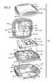
- FIG. 2is an exploded view of an exemplary embodiment of the wireless network device of FIG. 1 , which includes wireless logic encased by a heat dissipation unit that, in turn, is surrounded by a casing.
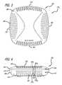
- FIG. 3is an overhead view of an exemplary embodiment of the wireless network device of FIG. 2 .
- FIG. 4is a front side view of an exemplary embodiment of the wireless network device of FIG. 3 .
- FIG. 5is a bottom view of an exemplary embodiment of the wireless network device of FIG. 3 .
- FIG. 6is a perspective view of an exemplary embodiment of the heat dissipation unit for the wireless network device of FIG. 2 .
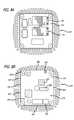
- FIGS. 7A & 7Bare exemplary embodiments of a top and bottom surface of a first section of the heat dissipation unit of FIG. 6 .
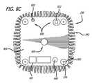
- FIGS. 8A , 8 B and 8 Care exemplary embodiments of a top and bottom surface of a second section of the heat dissipation unit of FIG. 6 .
- FIG. 9is an exemplary embodiment of a method of formulating the access point of FIG. 1 .
- Embodiments of the inventionrelate to a wireless network device comprising a casing and a heat dissipation unit which encases wireless logic and operates in concert with the casing to dissipate heat generated by the wireless logic by convection.
- the heat dissipation unitfeatures a plurality of sections that (i) collectively form a cavity into which wireless logic is placed and (ii) provide a heat path to a plurality of heat-radiating elements that are adapted to minimize the size of the casing but strive to increase the unit's surface area for effective cooling by convection.
- the heat-radiating elementsare elements positioned along a periphery of the unit and may have any of a number of form factors such as fins, pins or any geometric shape.
- the casingfeatures slots predominantly aligned with the spacing areas between the heat-radiating elements.
- Both the casing and the heat dissipation unitfeature apertures that, among other things, provide access to connectors in electrical communication with the wireless logic.
- logicis generally defined as hardware and/or software.
- logicmay include circuitry such as processing circuitry (e.g., a microprocessor, a programmable gate array, a controller, an application specific integrated circuit, etc.), wireless chipset with receiver and/or transmitter circuitry, semiconductor memory, combinatorial logic, or the like.
- processing circuitrye.g., a microprocessor, a programmable gate array, a controller, an application specific integrated circuit, etc.
- wireless chipsetwith receiver and/or transmitter circuitry
- semiconductor memorycombinatorial logic, or the like.
- the logicmay be one or more software modules, which are executable code such as an application, an applet, a routine, or one or more instructions.
- Software modulesmay be stored in any type of memory, namely suitable storage medium such as a programmable electronic circuit, a semiconductor memory device including a volatile memory (e.g., random access memory, etc.), any type of non-volatile memory (e.g., read-only memory, flash memory, a hard drive, etc.), a portable memory device (e.g., an optical disk, a Universal Serial Bus “USB” flash drive), or the like.
- suitable storage mediumsuch as a programmable electronic circuit, a semiconductor memory device including a volatile memory (e.g., random access memory, etc.), any type of non-volatile memory (e.g., read-only memory, flash memory, a hard drive, etc.), a portable memory device (e.g., an optical disk, a Universal Serial Bus “USB” flash drive), or the like.
- suitable storage mediumsuch as a programmable electronic circuit, a semiconductor memory device including a volatile memory (e.g., random access memory, etc.), any type of non-
- a “wireless network device”generally represents electronics with wireless capabilities or that support wireless communications such as an Access Point (AP), a station (e.g., any data processing equipment that is operable by a user such as a computer, cellular phone, personal digital assistant, tablet computer, etc.), a data transfer device (e.g., network switch), or the like.
- An “interconnect”is generally defined as a communication pathway established over an information-carrying medium.
- This information-carrying mediummay be a physical medium (e.g., electrical wire, optical fiber, cable, bus traces, etc.), a wireless medium (e.g., air in combination with wireless signaling technology) or a combination thereof.
- enterprise network 100includes at least one local area network 110 .
- Local area network 110may be adapted with an enhancement that allows wireless access, thereby operating as a wireless local area network (WLAN).
- WLANwireless local area network
- Interconnect 140may be established using a wired and/or wireless information-carrying medium and provides either a direct or indirect communication path between APs 130 1 - 130 X and network switch 120 .
- one or more wireless stationsmay be in communication with APs 130 1 - 130 X over wireless interconnects 160 .
- Wireless logicmay be implemented as a wireless chipset within STA 150 1 - 150 Y or as a removable, wireless network interface card (NIC).
- each AP 130 1 or 130 2supports bi-directional communications by receiving wireless messages from any or all of the STAs 150 1 - 150 Y within its coverage area and transferring information extracted from the wireless messages over interconnect 140 to which network switch 120 is coupled.
- STAs 150 1 - 150 Yare adapted to communicate with and provide information to any associated AP 130 1 , . . . , or 130 X .
- STAs 150 1 - 150 2may be associated with AP 130 1 and communicates over the air in accordance with a selected wireless communications protocol.
- AP 130 1may be adapted to operate as a transparent bridge connecting together a wireless and wired network.
- STA 150 3may be associated with AP 130 2 .
- AP 130 1may only support uni-directional transmissions thereby featuring only receive (RX) or transmit (TX) functionality.
- interconnect 140further provides connectivity for network resources such as servers for data storage, web servers or the like. These network resources are available for users of network 100 of FIG. 1 , albeit access may be restricted.
- network switch 120comprises logic that supports bi-directional communications with APs 130 1 - 130 X over interconnect 140 . Namely, network switch 120 receives messages from and transmitting messages to one or more targeted APs 130 1 , . . . , or 130 X over interconnect 140 .
- interconnect 140may be part of any type of wired network, including but not limited or restricted to Ethernet, Token Ring, Asynchronous Transfer Mode (ATM), or the like.
- ATMAsynchronous Transfer Mode
- an APe.g., AP 130 1
- wireless network device 130 1comprises wireless logic 200 encased by a heat dissipation unit 210 (e.g., a heat sink) that, in turn, is surrounded by a casing 250 .
- wireless logic 200is contained within a cavity 215 formed when one section 220 of heat dissipation unit 210 is placed over and mates with another section 230 .
- Both first section 220 and second section 230 of heat dissipation unit 210include heat-radiating elements 240 (e.g., fins 240 ) positioned around their peripheries in order to dissipate heat by convection.
- heat-radiating elements 240are represented as a first set of fins 242 and a second set of fins 244 according to this embodiment of the invention.
- wireless logic 200comprises a circuit board 202 that is sized for placement within a polygon-shaped body 232 of second section 230 .
- circuit board 202is positioned below a top surface of a first flange 234 that extends laterally from two or more inner sidewalls of body 232 to create a recessed groove.
- the first set of fins 242extends laterally from the outer sidewalls of body 232 .
- first section 220 of heat dissipation unit 210comprises a body 222 that is sized similarly to body 232 .
- a second flange 224extends vertically from at least two inner sidewalls of body 222 so that second flange 224 rests in the recessed groove formed by first flange 234 .
- a sufficient amount of spacingis created between an inner top surface of body 222 and wireless logic 200 that is mounted on circuit board 202 .
- the outer sidewalls of body 222feature the second set of fins 244 , which are aligned with first set of fins 242 .
- a heat transfer pathis provided by thermal pads 245 and 825 , which are positioned to be in thermal contact with wireless logic 200 when body 222 is situated over circuit board 222 and when circuit board 202 is situated in second section 230 .
- Heat radiating componentse.g., fins 240 ) provide thermal dissipation through convection.
- casing 250comprises an upper cover 260 and a lower cover 280 .
- Upper cover 260features a plurality of slots 265 that are oriented in an acutely angled (but generally horizontal) direction. Slots 265 are located near an edge portion of upper cover 260 in order to be aligned with the spacing areas formed between first and second sets of heat-radiating elements 242 & 244 (e.g., fins).
- LEDlight emitting diode
- casing 250comprises an upper cover 260 and a lower cover 280 .
- LEDlight emitting diode
- upper cover 260also features multiple bosses 275 , which are partially illustrated in FIG. 2 . These bosses 275 are sized for insertion into recesses 228 located along a corner area of body 222 .
- Lower cover 280features a plurality of slots 285 that are (i) arc-shaped (but vertically oriented), (ii) located around its periphery, and (iii) aligned with spacing areas formed between both first and second sets of heat-radiating elements 242 and 244 .
- lower cover 280comprises a plurality of openings that include one or more of the following:
- Brackets 295are positioned near the center of the outer surface of lower cover 280 . Brackets 295 are used to secure wireless network device 130 1 to a substantially flat surface such as a wall or a ceiling.
- an interior surface of lower cover 280comprises a plurality of bosses 296 that are adapted to protrude into recesses 236 located along a corner area of body 232 .
- fastening memberse.g., screw, bolt, etc.
- apertures 297 located behind bosses 296can be inserted through apertures 297 located behind bosses 296 , through apertures in bosses 296 of lower cover 280 , through apertures in recesses 236 of second section 230 , through apertures in circuit board 202 , through apertures in recesses 228 of first section 220 , and attached to bosses 275 of upper cover 260 .
- wireless device 130 1comprises casing 250 that includes upper cover 260 .
- upper cover 260comprises slots 265 located proximate to its periphery, namely slots located along each side 300 , 305 , 310 and 315 of upper cover 260 .
- slots 265may vary in size.
- slots 265 along sides 300 and 310are generally uniform and substantially aligned with the spacing areas between heat-radiating fins 244 of FIG. 2 .
- Slots along sides 305 and 315vary in size with a portion of these slots aligned downwardly with the spacing areas between heat-radiating fins 244 of FIG. 2 while the remaining portion of these slots are situated above body 222 of first section 220 of heat dissipation unit 210 .
- wireless device 130 1comprises casing 250 that includes edges 400 of upper cover 260 corresponding in shape to edges 410 of lower cover 280 .
- casing 250completely surrounds and covers heat dissipation unit 210 .
- casing 250includes slots 265 in upper cover 260 aligned in a generally downward direction with spacing area between heat-radiating fins 242 & 244 and slots 285 in lower cover 280 that are aligned in an upward facing and lateral directions with spacing area between heat-radiating fins 242 & 244 .
- Slots 265 and 285correspond in number and position in order to encourage air flow through these slots and through the spacing areas between heat-radiating fins 242 and 244 .
- lower cover 280comprises slots 285 located around its periphery, namely slots 420 located along a front side 430 of wireless device 130 1 , which may be similar to those slots (not shown) located along the other sides 435 , 440 and 445 of lower cover 280 .
- slots 420may vary in size based on differences in the length of each corresponding set of heat-radiating elements (e.g. fins) 242 and 244 .
- a lower portion 422 of slot 420 1is aligned with a spacing area between two neighboring heat-radiating fins 242 1 and 242 2 of second section 230 for heat dissipating unit 210 .
- An upper portion 424 of slot 420 1is aligned with a spacing area between two neighboring heat-radiating fins 244 1 and 244 2 of first section 220 for heat dissipating unit 210 , which are aligned with neighboring heat-radiating fins 242 1 and 242 2 , respectively.
- Differences in fin sizeswarrant differences in slot sizes as the area between the fins will be different as well.
- wireless device 130 1comprises casing 250 that includes lower cover 280 having a bottom surface 500 .
- Mounting brackets 295positioned along a mid-section of bottom surface 500 , are used to secure wireless network device 130 1 to a wall, a ceiling or another substantially flat surface.
- bottom surface 500 of wireless device 130 1is adapted with a plurality of openings 290 to allow for wired connectivity, a supply of power, and fastening.
- openings 290may include opening 291 that is sized to allow for insertion of one or more connectors into one or more corresponding inputs (e.g. any registered jack “RJ-xx” such as RJ-11, RJ-14, RJ-21, RJ-45, RJ-48, RJ-49, RJ-61; Universal Serial Bus “USB” port, etc.).
- RJ-xxregistered jack “RJ-xx” such as RJ-11, RJ-14, RJ-21, RJ-45, RJ-48, RJ-49, RJ-61; Universal Serial Bus “USB” port, etc.
- another opening 292may be placed within bottom surface 500 of lower cover 280 to allow for insertion and coupling of a female direct current (DC) power connector (e.g., direct current “DC” connector) to a male DC connector located within a cylindrical aperture within body 232 of second section 230 shown in FIG. 2 .
- DCdirect current
- Thisenables a supply of external power to wireless logic 200 within wireless network device 130 1 .
- other power connectorsmay be used in lieu of the DC power connector as illustrated.
- another opening 293may be placed within bottom surface 500 of lower cover 280 to enable second section 230 of heat dissipation unit 210 to be secured to lower cover 280 .
- heat dissipation unit 210is secured to that portion of wireless network device 130 1 secured to a surface, thereby preventing a situation where heat dissipation unit 210 becomes dislodged from casing 250 .
- Thismay be accomplished by implementing a locking mechanism that is positioned within casing 250 near an inner surface of bottom surface 500 or externally from casing 250 .
- Another opening 294may be placed within bottom surface 500 of lower cover 280 to enable access to a reset button. This provides a mechanism for an administrator or user to reset the functionality of wireless network device 130 1 .
- FIG. 6is a perspective view of an exemplary embodiment of heat dissipation unit 210 for wireless network device 130 1 of FIG. 2 .
- heat dissipation unit 210is configured as a heat sink that radiates (by convection) heat generated by wireless logic (not shown) encased by the heat sink.
- Heat dissipation unit 210comprises first section 220 that is placed over and mates with second section 230 . Both sections 220 and 230 are made of a material supporting thermal conductivity, such as an aluminum alloy or another metal alloy.
- second section 230includes body 232 with the first set of fins 242 positioned around its periphery and extending laterally therefrom. Second section 230 is configured for allowing connectivity to a wired network.
- first section 220includes body 222 with the second set of fins 244 positioned around its periphery. Both sets of fins 242 and 244 are configured to dissipate heat by convection.
- First section 220is configured for allowing connectivity to a wireless network as described below.
- first section 220includes body 222 that partially encases wireless logic with fins 244 extending laterally from sidewalls 700 , 705 , 710 and 715 of body 222 .
- Body 222comprises apertures 226 that operate as conduits for light emitted by light emitting diodes (LEDs) that are situated near one end of a conduit.
- Body 222further comprises recesses 228 placed within a top exterior surface 720 of first section 220 , which are located within corner areas of body 222 according to this embodiment.
- Recesses 228are adapted to receive bosses (not shown) projecting from the interior surface of the upper cover and attached together by fastening elements.
- a plurality of antennae 730are positioned on a top exterior surface 720 to receive wireless signaling and transmit such signaling to wireless logic 200 .
- a first plurality of antennae 732are coupled to a first chipset 740 and a second plurality of antennae 734 are coupled to a second chipset 745 .
- Chipsets 740 and 745form part of wireless logic 200 .
- first section 220includes body 222 that partially encases wireless logic with fins 244 extending laterally from sidewalls 700 , 705 , 710 and 715 of body 222 .
- a bottom interior surface 750 of body 222is concave in shape to provide sufficient spacing between surface 750 and the encased wireless logic.
- second flange 224is situated along all of an inner region of sidewalls 700 , 705 , 710 and 715 for insertion into the recessed groove formed within an interior region of second section 230 .
- Heat transfer element(s) 245such as a thermal pad(s), is coupled to an interior surface of body 222 (e.g., bottom surface 750 ) and transfers heat from the wireless logic. This creates a thermal dissipation path from the wireless logic to heat-radiating elements 244 .
- second section 230includes body 232 that partially encases wireless logic with fins 242 extending laterally from sidewalls 800 , 805 , 810 and 815 of body 232 .
- Circuit board 202rests within an interior surface 820 of body 232 below second flange 234 that forms a recessed groove along sidewall 800 , 805 , 810 and 815 .
- circuit board 202is supported and maintained level by supportive thermal members 825 positioned along interior surface 820 .
- Support membersprovide sufficient spacing between interior surface 820 and circuit board 202 to allow RJ-connectors and other circuitry and mechanisms to be substantially contained within heat dissipation unit 210 and provide a thermal heat path from the wireless logic to second section 230 .
- second section 230features a plurality of openings 830 that correspond to some or all of openings 290 in casing 250 of FIG. 5 .
- opening 831corresponds to opening 291 and also is sized to allow for insertion of one or more connectors therethrough (e.g. RJ-xx jacks, USB ports, etc.).
- another opening 832may be placed within second section 230 to expose a direct current (DC) power connector (e.g., direct current “DC” connector).
- DCdirect current
- opening 833may be placed within second section 230 to expose a reset button. This reset button provides a mechanism to reset the functionality of wireless network device 130 1 .
- recesses 236 and 840may be placed within an exterior bottom surface 850 of second section 230 .
- recesses 236are located along a corner area of body 232 although other locations may be used.
- Apertures 855are in the recesses to allow for fastening members (e.g., screw, bolt, etc.) to be inserted there through for securing heat dissipation unit 210 and casing 250 together.
- Recess 840may be a location within which a locking mechanism (not shown) is deployed to avoid the casing (not shown) from being separated from the heat dissipation unit.
- one section (e.g., second section) of a heat dissipation unite.g., heat sink
- a circuit board with wireless logicis positioned within the second section of the heat sink and subsequently encased by another section of the heat sink (e.g., first section) as illustrated in blocks 910 and 920 .
- antenna(e)are positioned on a top surface of the first section of the heat sink (block 930 ).
- the antenna(e)may be positioned on a bottom surface of the second section.
- Interconnectsare used to connect the antenna(e) to the wireless logic through feed areas within the first section (block 940 ). Thereafter, an upper cover of the casing is placed over the first section of the heat sink so that the casing encases the heat sink, which encases the wireless logic (block 950 ). Fastening elements are inserted through areas within at least the casing and the heat sink to secure these elements together (block 960 ).
Landscapes
- Engineering & Computer Science (AREA)
- Theoretical Computer Science (AREA)
- Physics & Mathematics (AREA)
- General Physics & Mathematics (AREA)
- Computer Hardware Design (AREA)
- Human Computer Interaction (AREA)
- General Engineering & Computer Science (AREA)
- Chemical & Material Sciences (AREA)
- Materials Engineering (AREA)
- Condensed Matter Physics & Semiconductors (AREA)
- Microelectronics & Electronic Packaging (AREA)
- Power Engineering (AREA)
- Cooling Or The Like Of Electrical Apparatus (AREA)
Abstract
Description
- (1) one or
more openings 291 that are adapted to provide access to predefined aperture(s) inheat dissipation unit 210 through which connectors are accessible. These connectors enable electrical communications between wireless logic200 (encased by heat dissipation unit210) and an external device (e.g., network switch); - (2) an
opening 292 for receipt of a power connector; - (3) an
opening 293 for a locking mechanism that is used to secureheat dissipation unit 210 tolower cover 280; and - (4) an
opening 294 for access to a reset button.
- (1) one or
Claims (26)
Priority Applications (2)
| Application Number | Priority Date | Filing Date | Title |
|---|---|---|---|
| US12/971,962US8681501B2 (en) | 2010-12-17 | 2010-12-17 | Heat dissipation unit for a wireless network device |
| PCT/US2011/041001WO2012082181A1 (en) | 2010-12-17 | 2011-06-17 | Heat dissipation unit for a wireless network device |
Applications Claiming Priority (1)
| Application Number | Priority Date | Filing Date | Title |
|---|---|---|---|
| US12/971,962US8681501B2 (en) | 2010-12-17 | 2010-12-17 | Heat dissipation unit for a wireless network device |
Publications (2)
| Publication Number | Publication Date |
|---|---|
| US20120155015A1 US20120155015A1 (en) | 2012-06-21 |
| US8681501B2true US8681501B2 (en) | 2014-03-25 |
Family
ID=46234129
Family Applications (1)
| Application Number | Title | Priority Date | Filing Date |
|---|---|---|---|
| US12/971,962Active2032-01-10US8681501B2 (en) | 2010-12-17 | 2010-12-17 | Heat dissipation unit for a wireless network device |
Country Status (2)
| Country | Link |
|---|---|
| US (1) | US8681501B2 (en) |
| WO (1) | WO2012082181A1 (en) |
Cited By (20)
| Publication number | Priority date | Publication date | Assignee | Title |
|---|---|---|---|---|
| US20130050942A1 (en)* | 2011-08-30 | 2013-02-28 | Sony Corporation | Electronic apparatus |
| US20140118920A1 (en)* | 2012-10-31 | 2014-05-01 | Hewlett-Packard Development Company, L.P. | Multi-function module for insertion into a networking chassis slot |
| US20160144233A1 (en)* | 2014-11-24 | 2016-05-26 | Adidas Ag | Activity monitoring base station |
| US20170150650A1 (en)* | 2015-11-24 | 2017-05-25 | Cisco Technology, Inc. | Dual purpose wireless device packaging |
| US9775257B2 (en)* | 2014-01-16 | 2017-09-26 | Mitsubishi Electric Corporation | Electronic device unit and electronic device |
| US20170301375A1 (en)* | 2014-09-25 | 2017-10-19 | Evtron, Inc. | Heat and flow management in a computing device |
| US20180095503A1 (en)* | 2016-09-30 | 2018-04-05 | Intel Corporation | Compartment for magnet placement |
| US20200093034A1 (en)* | 2017-05-19 | 2020-03-19 | Commscope Technologies Llc | Telecommunications enclosure with separate heat sink assembly |
| US20200214131A1 (en)* | 2019-01-02 | 2020-07-02 | The Boeing Company | Multi-embedded radio frequency board and mobile device including the same |
| US11122707B2 (en)* | 2018-07-12 | 2021-09-14 | Arris Enterprises Llc | Raised pathway heat sink |
| US11129309B2 (en)* | 2018-03-27 | 2021-09-21 | Mitsubishi Electric Corporation | Cooling device, lid-equipped cooling device, case with cooling device, and inverter |
| US20210303038A1 (en)* | 2020-03-27 | 2021-09-30 | Sony Interactive Entertainment Inc. | Electronic apparatus and exterior panel thereof |
| US11184998B2 (en)* | 2014-12-03 | 2021-11-23 | Sagemcom Broadband Sas | Electronic device provided with an antenna integrated into a heatsink |
| US20220078941A1 (en)* | 2019-10-15 | 2022-03-10 | Cisco Technology, Inc. | Corrosion preventive heatsink for network device |
| US20220127013A1 (en)* | 2020-10-23 | 2022-04-28 | CCX Technologies | Secure avioncs wireless access point device with heat sink enclosure |
| US20220142010A1 (en)* | 2019-08-30 | 2022-05-05 | Huawei Technologies Co., Ltd. | Vehicle-mounted device and vehicle |
| US11349187B1 (en)* | 2020-08-25 | 2022-05-31 | Waymo Llc | Modular telematics control unit with directional Bluetooth low energy |
| US20240179881A1 (en)* | 2021-08-17 | 2024-05-30 | Mornsun Guangzhou Science & Technology Co., Ltd. | Switching power supply structure |
| US20240397670A1 (en)* | 2023-05-24 | 2024-11-28 | Alpha Networks Inc. | Heat dissipation structure and electronic device using same |
| US12298823B2 (en) | 2020-03-27 | 2025-05-13 | Sony Interactive Entertainment Inc. | Electronic apparatus and exterior panel thereof |
Families Citing this family (53)
| Publication number | Priority date | Publication date | Assignee | Title |
|---|---|---|---|---|
| US9354748B2 (en) | 2012-02-13 | 2016-05-31 | Microsoft Technology Licensing, Llc | Optical stylus interaction |
| US9298236B2 (en) | 2012-03-02 | 2016-03-29 | Microsoft Technology Licensing, Llc | Multi-stage power adapter configured to provide a first power level upon initial connection of the power adapter to the host device and a second power level thereafter upon notification from the host device to the power adapter |
| USRE48963E1 (en) | 2012-03-02 | 2022-03-08 | Microsoft Technology Licensing, Llc | Connection device for computing devices |
| US9075566B2 (en) | 2012-03-02 | 2015-07-07 | Microsoft Technoogy Licensing, LLC | Flexible hinge spine |
| US8873227B2 (en) | 2012-03-02 | 2014-10-28 | Microsoft Corporation | Flexible hinge support layer |
| US9870066B2 (en) | 2012-03-02 | 2018-01-16 | Microsoft Technology Licensing, Llc | Method of manufacturing an input device |
| US9064654B2 (en) | 2012-03-02 | 2015-06-23 | Microsoft Technology Licensing, Llc | Method of manufacturing an input device |
| US9426905B2 (en) | 2012-03-02 | 2016-08-23 | Microsoft Technology Licensing, Llc | Connection device for computing devices |
| US9460029B2 (en) | 2012-03-02 | 2016-10-04 | Microsoft Technology Licensing, Llc | Pressure sensitive keys |
| US9360893B2 (en) | 2012-03-02 | 2016-06-07 | Microsoft Technology Licensing, Llc | Input device writing surface |
| US9063693B2 (en) | 2012-06-13 | 2015-06-23 | Microsoft Technology Licensing, Llc | Peripheral device storage |
| US9073123B2 (en)* | 2012-06-13 | 2015-07-07 | Microsoft Technology Licensing, Llc | Housing vents |
| US9459160B2 (en) | 2012-06-13 | 2016-10-04 | Microsoft Technology Licensing, Llc | Input device sensor configuration |
| US9684382B2 (en) | 2012-06-13 | 2017-06-20 | Microsoft Technology Licensing, Llc | Input device configuration having capacitive and pressure sensors |
| US8964379B2 (en) | 2012-08-20 | 2015-02-24 | Microsoft Corporation | Switchable magnetic lock |
| US8654030B1 (en) | 2012-10-16 | 2014-02-18 | Microsoft Corporation | Antenna placement |
| WO2014059625A1 (en) | 2012-10-17 | 2014-04-24 | Microsoft Corporation | Metal alloy injection molding overflows |
| WO2014059618A1 (en) | 2012-10-17 | 2014-04-24 | Microsoft Corporation | Graphic formation via material ablation |
| EP2908970B1 (en) | 2012-10-17 | 2018-01-03 | Microsoft Technology Licensing, LLC | Metal alloy injection molding protrusions |
| US9385416B2 (en)* | 2013-01-15 | 2016-07-05 | Aruba Networks, Inc. | Three dimensional antenna dome array |
| US10578499B2 (en) | 2013-02-17 | 2020-03-03 | Microsoft Technology Licensing, Llc | Piezo-actuated virtual buttons for touch surfaces |
| EP2978293A4 (en)* | 2013-03-19 | 2017-02-15 | Fuji Electric Co., Ltd. | Cooling device and power converter provided with same |
| EP2978291A4 (en)* | 2013-03-19 | 2016-11-02 | Fuji Electric Co Ltd | ELECTRONIC DEVICE COOLING APPARATUS AND POWER CONVERTING APPARATUS HAVING THE SAME |
| US9230878B2 (en)* | 2013-04-12 | 2016-01-05 | Lenovo Enterprise Solutions (Singapore) Pte. Ltd. | Integrated circuit package for heat dissipation |
| WO2015023447A2 (en)* | 2013-08-16 | 2015-02-19 | Technicolor Usa, Inc. | Multi-layer heat spreader assembly with isolated convective fins |
| US9448631B2 (en) | 2013-12-31 | 2016-09-20 | Microsoft Technology Licensing, Llc | Input device haptics and pressure sensing |
| US10120420B2 (en) | 2014-03-21 | 2018-11-06 | Microsoft Technology Licensing, Llc | Lockable display and techniques enabling use of lockable displays |
| US10324733B2 (en) | 2014-07-30 | 2019-06-18 | Microsoft Technology Licensing, Llc | Shutdown notifications |
| US9424048B2 (en) | 2014-09-15 | 2016-08-23 | Microsoft Technology Licensing, Llc | Inductive peripheral retention device |
| US20160095252A1 (en)* | 2014-09-25 | 2016-03-31 | Thomson Licensing | Vertical electronic device with curved top surface design |
| US10222889B2 (en) | 2015-06-03 | 2019-03-05 | Microsoft Technology Licensing, Llc | Force inputs and cursor control |
| US10416799B2 (en) | 2015-06-03 | 2019-09-17 | Microsoft Technology Licensing, Llc | Force sensing and inadvertent input control of an input device |
| US10061385B2 (en) | 2016-01-22 | 2018-08-28 | Microsoft Technology Licensing, Llc | Haptic feedback for a touch input device |
| US9913411B2 (en)* | 2016-04-27 | 2018-03-06 | General Electric Company | Thermal capacitance system |
| CN106449563B (en)* | 2016-11-29 | 2018-11-13 | 卡姆丹克太阳能(江苏)有限公司 | A kind of wafer level packaging with fin structure |
| CN106449443B (en)* | 2016-11-29 | 2019-01-01 | 海安浩驰科技有限公司 | A kind of wafer packaging method with fin structure |
| JP6743221B1 (en)* | 2019-03-18 | 2020-08-19 | Necプラットフォームズ株式会社 | Heat dissipation structure |
| KR102290036B1 (en)* | 2019-05-15 | 2021-08-18 | 주식회사 케이엠더블유 | Antenna apparatus |
| KR20200132041A (en)* | 2019-05-15 | 2020-11-25 | 삼성전자주식회사 | Electronic device including heat radiating structure |
| US11260976B2 (en) | 2019-11-15 | 2022-03-01 | General Electric Company | System for reducing thermal stresses in a leading edge of a high speed vehicle |
| US11427330B2 (en) | 2019-11-15 | 2022-08-30 | General Electric Company | System and method for cooling a leading edge of a high speed vehicle |
| US11260953B2 (en) | 2019-11-15 | 2022-03-01 | General Electric Company | System and method for cooling a leading edge of a high speed vehicle |
| US11352120B2 (en) | 2019-11-15 | 2022-06-07 | General Electric Company | System and method for cooling a leading edge of a high speed vehicle |
| US11267551B2 (en) | 2019-11-15 | 2022-03-08 | General Electric Company | System and method for cooling a leading edge of a high speed vehicle |
| US11695438B2 (en)* | 2019-12-23 | 2023-07-04 | Veea Inc. | Expandable architecture and bus for consumer gateway |
| US12075593B2 (en) | 2020-03-27 | 2024-08-27 | Sony Interactive Entertainment Inc. | Electronic apparatus |
| DE102020207574B3 (en) | 2020-06-18 | 2021-09-09 | Continental Automotive Gmbh | Antenna module |
| US11516883B2 (en)* | 2020-08-03 | 2022-11-29 | Inseego Corp. | Modular 5G fixed wireless access device |
| US11606882B2 (en)* | 2020-11-05 | 2023-03-14 | Bae Systems Information And Electronic Systems Integration Inc. | Aerothermal ring structures providing RF isolation |
| US11745847B2 (en) | 2020-12-08 | 2023-09-05 | General Electric Company | System and method for cooling a leading edge of a high speed vehicle |
| US11407488B2 (en) | 2020-12-14 | 2022-08-09 | General Electric Company | System and method for cooling a leading edge of a high speed vehicle |
| US11577817B2 (en) | 2021-02-11 | 2023-02-14 | General Electric Company | System and method for cooling a leading edge of a high speed vehicle |
| CN118312019A (en)* | 2024-03-29 | 2024-07-09 | 比特小鹿半导体科技有限公司 | Power calculating host and server |
Citations (19)
| Publication number | Priority date | Publication date | Assignee | Title |
|---|---|---|---|---|
| US5353191A (en) | 1993-03-08 | 1994-10-04 | The Whitaker Corporation | Combination heat sink and housing for flexible electrical connector used in an electrical or electronic assembly |
| US5842514A (en) | 1997-03-05 | 1998-12-01 | Northern Telecom Limited | Electronic unit |
| US6147859A (en)* | 1999-08-18 | 2000-11-14 | Ops, Inc. | Modular external peripheral housing |
| US6510226B1 (en) | 1997-11-24 | 2003-01-21 | Lucent Technologies Inc. | Dual network housing device |
| US6864573B2 (en) | 2003-05-06 | 2005-03-08 | Daimlerchrysler Corporation | Two piece heat sink and device package |
| US6934150B2 (en)* | 2001-08-10 | 2005-08-23 | Sun Microsystems, Inc. | Computer module housing |
| US7019974B2 (en) | 2004-07-16 | 2006-03-28 | Hon Hai Precision Industry Co., Ltd. | Heat dissipation device |
| US20060082973A1 (en)* | 2004-10-14 | 2006-04-20 | Egbert David K | Wireless router |
| US20060133033A1 (en)* | 2004-12-20 | 2006-06-22 | Harris Corporation | Heat exchanger system for circuit card assemblies |
| US7423875B2 (en)* | 2006-06-26 | 2008-09-09 | Silver-Stone Technology Co., Ltd. | Liquid-cooling heat dissipating device for dissipating heat by a casing |
| US7747272B2 (en) | 2006-05-01 | 2010-06-29 | Ortronics, Inc. | Wireless access point with temperature control system |
| US7817428B2 (en)* | 2008-06-27 | 2010-10-19 | Greer Jr David Randall | Enclosure with integrated heat wick |
| US7848105B2 (en)* | 2004-01-08 | 2010-12-07 | Apple Inc. | Apparatus for air cooling of an electronic device |
| US7859837B2 (en)* | 2005-05-24 | 2010-12-28 | Thales | Modular electronic device operating in difficult environments |
| US7898810B2 (en)* | 2008-12-19 | 2011-03-01 | Raytheon Company | Air cooling for a phased array radar |
| US7903412B2 (en)* | 2009-01-14 | 2011-03-08 | Cisco Technology, Inc. | Mounting socket that dissipates heat from a network device |
| US7990726B2 (en)* | 2007-07-02 | 2011-08-02 | Fujitsu Limited | Tray-type structure device |
| US8279604B2 (en)* | 2010-08-05 | 2012-10-02 | Raytheon Company | Cooling system for cylindrical antenna |
| US8422232B2 (en)* | 2008-08-13 | 2013-04-16 | Electronics And Telecommunications Research Institute | System for controlling temperature of antenna module |
- 2010
- 2010-12-17USUS12/971,962patent/US8681501B2/enactiveActive
- 2011
- 2011-06-17WOPCT/US2011/041001patent/WO2012082181A1/enactiveApplication Filing
Patent Citations (19)
| Publication number | Priority date | Publication date | Assignee | Title |
|---|---|---|---|---|
| US5353191A (en) | 1993-03-08 | 1994-10-04 | The Whitaker Corporation | Combination heat sink and housing for flexible electrical connector used in an electrical or electronic assembly |
| US5842514A (en) | 1997-03-05 | 1998-12-01 | Northern Telecom Limited | Electronic unit |
| US6510226B1 (en) | 1997-11-24 | 2003-01-21 | Lucent Technologies Inc. | Dual network housing device |
| US6147859A (en)* | 1999-08-18 | 2000-11-14 | Ops, Inc. | Modular external peripheral housing |
| US6934150B2 (en)* | 2001-08-10 | 2005-08-23 | Sun Microsystems, Inc. | Computer module housing |
| US6864573B2 (en) | 2003-05-06 | 2005-03-08 | Daimlerchrysler Corporation | Two piece heat sink and device package |
| US7848105B2 (en)* | 2004-01-08 | 2010-12-07 | Apple Inc. | Apparatus for air cooling of an electronic device |
| US7019974B2 (en) | 2004-07-16 | 2006-03-28 | Hon Hai Precision Industry Co., Ltd. | Heat dissipation device |
| US20060082973A1 (en)* | 2004-10-14 | 2006-04-20 | Egbert David K | Wireless router |
| US20060133033A1 (en)* | 2004-12-20 | 2006-06-22 | Harris Corporation | Heat exchanger system for circuit card assemblies |
| US7859837B2 (en)* | 2005-05-24 | 2010-12-28 | Thales | Modular electronic device operating in difficult environments |
| US7747272B2 (en) | 2006-05-01 | 2010-06-29 | Ortronics, Inc. | Wireless access point with temperature control system |
| US7423875B2 (en)* | 2006-06-26 | 2008-09-09 | Silver-Stone Technology Co., Ltd. | Liquid-cooling heat dissipating device for dissipating heat by a casing |
| US7990726B2 (en)* | 2007-07-02 | 2011-08-02 | Fujitsu Limited | Tray-type structure device |
| US7817428B2 (en)* | 2008-06-27 | 2010-10-19 | Greer Jr David Randall | Enclosure with integrated heat wick |
| US8422232B2 (en)* | 2008-08-13 | 2013-04-16 | Electronics And Telecommunications Research Institute | System for controlling temperature of antenna module |
| US7898810B2 (en)* | 2008-12-19 | 2011-03-01 | Raytheon Company | Air cooling for a phased array radar |
| US7903412B2 (en)* | 2009-01-14 | 2011-03-08 | Cisco Technology, Inc. | Mounting socket that dissipates heat from a network device |
| US8279604B2 (en)* | 2010-08-05 | 2012-10-02 | Raytheon Company | Cooling system for cylindrical antenna |
Non-Patent Citations (1)
| Title |
|---|
| International Patent Application No. PCT/US2011/04001, The International Search Report and the Written Opinion of the International Searching Authority, mailed Oct. 20, 2011. |
Cited By (37)
| Publication number | Priority date | Publication date | Assignee | Title |
|---|---|---|---|---|
| US20130050942A1 (en)* | 2011-08-30 | 2013-02-28 | Sony Corporation | Electronic apparatus |
| US20140118920A1 (en)* | 2012-10-31 | 2014-05-01 | Hewlett-Packard Development Company, L.P. | Multi-function module for insertion into a networking chassis slot |
| US9161475B2 (en)* | 2012-10-31 | 2015-10-13 | Hewlett-Packard Development Company, L.P. | Multi-function module for insertion into a networking chassis slot |
| US9775257B2 (en)* | 2014-01-16 | 2017-09-26 | Mitsubishi Electric Corporation | Electronic device unit and electronic device |
| US20170301375A1 (en)* | 2014-09-25 | 2017-10-19 | Evtron, Inc. | Heat and flow management in a computing device |
| US10127949B2 (en)* | 2014-09-25 | 2018-11-13 | Evtron, Inc. | Heat and flow management in a computing device |
| US10478668B2 (en)* | 2014-11-24 | 2019-11-19 | Adidas Ag | Activity monitoring base station |
| US20160144233A1 (en)* | 2014-11-24 | 2016-05-26 | Adidas Ag | Activity monitoring base station |
| US11184998B2 (en)* | 2014-12-03 | 2021-11-23 | Sagemcom Broadband Sas | Electronic device provided with an antenna integrated into a heatsink |
| US20170150650A1 (en)* | 2015-11-24 | 2017-05-25 | Cisco Technology, Inc. | Dual purpose wireless device packaging |
| US9674985B1 (en)* | 2015-11-24 | 2017-06-06 | Cisco Technology, Inc. | Dual purpose wireless device packaging |
| US10317952B2 (en)* | 2016-09-30 | 2019-06-11 | Intel Corporation | Compartment for magnet placement |
| US20180095503A1 (en)* | 2016-09-30 | 2018-04-05 | Intel Corporation | Compartment for magnet placement |
| US20200093034A1 (en)* | 2017-05-19 | 2020-03-19 | Commscope Technologies Llc | Telecommunications enclosure with separate heat sink assembly |
| US11026349B2 (en)* | 2017-05-19 | 2021-06-01 | Commscope Technologies Llc | Telecommunications enclosure with separate heat sink assembly |
| US11129309B2 (en)* | 2018-03-27 | 2021-09-21 | Mitsubishi Electric Corporation | Cooling device, lid-equipped cooling device, case with cooling device, and inverter |
| US11122707B2 (en)* | 2018-07-12 | 2021-09-14 | Arris Enterprises Llc | Raised pathway heat sink |
| US11800685B2 (en) | 2018-07-12 | 2023-10-24 | Arris Enterprises Llc | Raised pathway heat sink |
| US20200214131A1 (en)* | 2019-01-02 | 2020-07-02 | The Boeing Company | Multi-embedded radio frequency board and mobile device including the same |
| US10912195B2 (en)* | 2019-01-02 | 2021-02-02 | The Boeing Company | Multi-embedded radio frequency board and mobile device including the same |
| US11375616B2 (en)* | 2019-01-02 | 2022-06-28 | The Boeing Company | Multi-embedded radio frequency board and mobile device including the same |
| US11839065B2 (en)* | 2019-08-30 | 2023-12-05 | Huawei Technologies Co., Ltd. | Temperature equalizing vehicle-mountable device |
| US20220142010A1 (en)* | 2019-08-30 | 2022-05-05 | Huawei Technologies Co., Ltd. | Vehicle-mounted device and vehicle |
| US20240215196A1 (en)* | 2019-10-15 | 2024-06-27 | Cisco Technology, Inc. | Corrosion preventive heatsink for network device |
| US20220078941A1 (en)* | 2019-10-15 | 2022-03-10 | Cisco Technology, Inc. | Corrosion preventive heatsink for network device |
| US11980005B2 (en)* | 2019-10-15 | 2024-05-07 | Cisco Technology, Inc. | Corrosion preventive heatsink for network device |
| US12298823B2 (en) | 2020-03-27 | 2025-05-13 | Sony Interactive Entertainment Inc. | Electronic apparatus and exterior panel thereof |
| US12253890B2 (en) | 2020-03-27 | 2025-03-18 | Sony Interactive Entertainment Inc. | Electronic apparatus and exterior panel thereof |
| US20210303038A1 (en)* | 2020-03-27 | 2021-09-30 | Sony Interactive Entertainment Inc. | Electronic apparatus and exterior panel thereof |
| US12066874B2 (en)* | 2020-03-27 | 2024-08-20 | Sony Interactive Entertainment Inc. | Electronic apparatus and exterior panel thereof |
| US20220278436A1 (en)* | 2020-08-25 | 2022-09-01 | Waymo Llc | Modular Telematics Control Unit with Directional Bluetooth Low Energy |
| US11848487B2 (en)* | 2020-08-25 | 2023-12-19 | Waymo Llc | Modular telematics control unit with directional Bluetooth low energy |
| US11349187B1 (en)* | 2020-08-25 | 2022-05-31 | Waymo Llc | Modular telematics control unit with directional Bluetooth low energy |
| US20220127013A1 (en)* | 2020-10-23 | 2022-04-28 | CCX Technologies | Secure avioncs wireless access point device with heat sink enclosure |
| US20240179881A1 (en)* | 2021-08-17 | 2024-05-30 | Mornsun Guangzhou Science & Technology Co., Ltd. | Switching power supply structure |
| US20240397670A1 (en)* | 2023-05-24 | 2024-11-28 | Alpha Networks Inc. | Heat dissipation structure and electronic device using same |
| US12408305B2 (en)* | 2023-05-24 | 2025-09-02 | Alpha Networks Inc. | Heat dissipation structure and electronic device using same |
Also Published As
| Publication number | Publication date |
|---|---|
| WO2012082181A1 (en) | 2012-06-21 |
| US20120155015A1 (en) | 2012-06-21 |
Similar Documents
| Publication | Publication Date | Title |
|---|---|---|
| US8681501B2 (en) | Heat dissipation unit for a wireless network device | |
| US10777877B2 (en) | Compact, direct plugged, and high-performance Wi-Fi access point | |
| US11800685B2 (en) | Raised pathway heat sink | |
| CN110880803B (en) | Wireless charging device | |
| JP6905136B2 (en) | Heat dissipation structure | |
| CN114503795B (en) | Thermal control system for mesh network devices and associated mesh network devices | |
| CN107210512B (en) | Radio unit housing and base station antenna module | |
| WO2023020554A1 (en) | Double-layer optical module apparatus and communication network device board | |
| CN112262507B (en) | Compact, direct-insertion, and high-performance Wi-Fi access point | |
| CN214852404U (en) | Control equipment | |
| JP2008243999A (en) | Heat dissipation parts and electronic equipment | |
| TWI495423B (en) | Thermal module and electronic device incorporating the same | |
| US7817424B2 (en) | Heat sink assembly including a heat pipe and a duct | |
| JP3225738U (en) | Electronics | |
| US7209353B2 (en) | Hermetically sealed access point for a wireless network | |
| KR102401788B1 (en) | Power over Ethernet access point with heat sink | |
| JP2018182149A (en) | Heat radiator | |
| JP6937409B2 (en) | Heat dissipation structure and Ethernet power access point including it | |
| CN216700838U (en) | Shell assembly of electronic equipment and electronic equipment | |
| CN223141954U (en) | Router | |
| JP7093384B2 (en) | Information communication equipment | |
| CN217240947U (en) | POE wireless access panel equipment and network communication system | |
| CN215454154U (en) | a plant lamp | |
| KR200409819Y1 (en) | Heat shield | |
| CN108366484A (en) | A kind of PCB and electronic equipment |
Legal Events
| Date | Code | Title | Description |
|---|---|---|---|
| AS | Assignment | Owner name:ARUBA NETWORKS, INC., CALIFORNIA Free format text:ASSIGNMENT OF ASSIGNORS INTEREST;ASSIGNORS:GOVINDASAMY, GURURAJ;NGUYEN, THOMAS;LEW, HOGAN;AND OTHERS;SIGNING DATES FROM 20110425 TO 20110426;REEL/FRAME:027861/0730 | |
| STCF | Information on status: patent grant | Free format text:PATENTED CASE | |
| AS | Assignment | Owner name:HEWLETT-PACKARD DEVELOPMENT COMPANY, L.P., TEXAS Free format text:ASSIGNMENT OF ASSIGNORS INTEREST;ASSIGNOR:ARUBA NETWORKS, INC.;REEL/FRAME:035814/0518 Effective date:20150529 | |
| AS | Assignment | Owner name:ARUBA NETWORKS, INC., CALIFORNIA Free format text:ASSIGNMENT OF ASSIGNORS INTEREST;ASSIGNOR:HEWLETT-PACKARD DEVELOPMENT COMPANY, L.P.;REEL/FRAME:036379/0274 Effective date:20150807 | |
| MAFP | Maintenance fee payment | Free format text:PAYMENT OF MAINTENANCE FEE, 4TH YEAR, LARGE ENTITY (ORIGINAL EVENT CODE: M1551) Year of fee payment:4 | |
| AS | Assignment | Owner name:HEWLETT PACKARD ENTERPRISE DEVELOPMENT LP, TEXAS Free format text:ASSIGNMENT OF ASSIGNORS INTEREST;ASSIGNOR:ARUBA NETWORKS, INC.;REEL/FRAME:045921/0055 Effective date:20171115 | |
| MAFP | Maintenance fee payment | Free format text:PAYMENT OF MAINTENANCE FEE, 8TH YEAR, LARGE ENTITY (ORIGINAL EVENT CODE: M1552); ENTITY STATUS OF PATENT OWNER: LARGE ENTITY Year of fee payment:8 |