US8680803B2 - Substrate processing apparatus with motors integral to chamber walls - Google Patents
Substrate processing apparatus with motors integral to chamber wallsDownload PDFInfo
- Publication number
- US8680803B2 US8680803B2US13/567,812US201213567812AUS8680803B2US 8680803 B2US8680803 B2US 8680803B2US 201213567812 AUS201213567812 AUS 201213567812AUS 8680803 B2US8680803 B2US 8680803B2
- Authority
- US
- United States
- Prior art keywords
- chamber
- stator
- rotor
- transport
- processing apparatus
- Prior art date
- Legal status (The legal status is an assumption and is not a legal conclusion. Google has not performed a legal analysis and makes no representation as to the accuracy of the status listed.)
- Active
Links
Images


Classifications
- H—ELECTRICITY
- H02—GENERATION; CONVERSION OR DISTRIBUTION OF ELECTRIC POWER
- H02K—DYNAMO-ELECTRIC MACHINES
- H02K41/00—Propulsion systems in which a rigid body is moved along a path due to dynamo-electric interaction between the body and a magnetic field travelling along the path
- H02K41/02—Linear motors; Sectional motors
- H02K41/03—Synchronous motors; Motors moving step by step; Reluctance motors
- B—PERFORMING OPERATIONS; TRANSPORTING
- B25—HAND TOOLS; PORTABLE POWER-DRIVEN TOOLS; MANIPULATORS
- B25J—MANIPULATORS; CHAMBERS PROVIDED WITH MANIPULATION DEVICES
- B25J11/00—Manipulators not otherwise provided for
- B25J11/0095—Manipulators transporting wafers
- B—PERFORMING OPERATIONS; TRANSPORTING
- B25—HAND TOOLS; PORTABLE POWER-DRIVEN TOOLS; MANIPULATORS
- B25J—MANIPULATORS; CHAMBERS PROVIDED WITH MANIPULATION DEVICES
- B25J9/00—Programme-controlled manipulators
- B25J9/0084—Programme-controlled manipulators comprising a plurality of manipulators
- B25J9/0087—Dual arms
- H—ELECTRICITY
- H01—ELECTRIC ELEMENTS
- H01L—SEMICONDUCTOR DEVICES NOT COVERED BY CLASS H10
- H01L21/00—Processes or apparatus adapted for the manufacture or treatment of semiconductor or solid state devices or of parts thereof
- H01L21/67—Apparatus specially adapted for handling semiconductor or electric solid state devices during manufacture or treatment thereof; Apparatus specially adapted for handling wafers during manufacture or treatment of semiconductor or electric solid state devices or components ; Apparatus not specifically provided for elsewhere
- H01L21/67005—Apparatus not specifically provided for elsewhere
- H01L21/67011—Apparatus for manufacture or treatment
- H01L21/67155—Apparatus for manufacturing or treating in a plurality of work-stations
- H01L21/67196—Apparatus for manufacturing or treating in a plurality of work-stations characterized by the construction of the transfer chamber
- H—ELECTRICITY
- H01—ELECTRIC ELEMENTS
- H01L—SEMICONDUCTOR DEVICES NOT COVERED BY CLASS H10
- H01L21/00—Processes or apparatus adapted for the manufacture or treatment of semiconductor or solid state devices or of parts thereof
- H01L21/67—Apparatus specially adapted for handling semiconductor or electric solid state devices during manufacture or treatment thereof; Apparatus specially adapted for handling wafers during manufacture or treatment of semiconductor or electric solid state devices or components ; Apparatus not specifically provided for elsewhere
- H01L21/677—Apparatus specially adapted for handling semiconductor or electric solid state devices during manufacture or treatment thereof; Apparatus specially adapted for handling wafers during manufacture or treatment of semiconductor or electric solid state devices or components ; Apparatus not specifically provided for elsewhere for conveying, e.g. between different workstations
- H01L21/67739—Apparatus specially adapted for handling semiconductor or electric solid state devices during manufacture or treatment thereof; Apparatus specially adapted for handling wafers during manufacture or treatment of semiconductor or electric solid state devices or components ; Apparatus not specifically provided for elsewhere for conveying, e.g. between different workstations into and out of processing chamber
- H01L21/67742—Mechanical parts of transfer devices
- H—ELECTRICITY
- H01—ELECTRIC ELEMENTS
- H01L—SEMICONDUCTOR DEVICES NOT COVERED BY CLASS H10
- H01L21/00—Processes or apparatus adapted for the manufacture or treatment of semiconductor or solid state devices or of parts thereof
- H01L21/67—Apparatus specially adapted for handling semiconductor or electric solid state devices during manufacture or treatment thereof; Apparatus specially adapted for handling wafers during manufacture or treatment of semiconductor or electric solid state devices or components ; Apparatus not specifically provided for elsewhere
- H01L21/677—Apparatus specially adapted for handling semiconductor or electric solid state devices during manufacture or treatment thereof; Apparatus specially adapted for handling wafers during manufacture or treatment of semiconductor or electric solid state devices or components ; Apparatus not specifically provided for elsewhere for conveying, e.g. between different workstations
- H01L21/67739—Apparatus specially adapted for handling semiconductor or electric solid state devices during manufacture or treatment thereof; Apparatus specially adapted for handling wafers during manufacture or treatment of semiconductor or electric solid state devices or components ; Apparatus not specifically provided for elsewhere for conveying, e.g. between different workstations into and out of processing chamber
- H01L21/67745—Apparatus specially adapted for handling semiconductor or electric solid state devices during manufacture or treatment thereof; Apparatus specially adapted for handling wafers during manufacture or treatment of semiconductor or electric solid state devices or components ; Apparatus not specifically provided for elsewhere for conveying, e.g. between different workstations into and out of processing chamber characterized by movements or sequence of movements of transfer devices
- H—ELECTRICITY
- H01—ELECTRIC ELEMENTS
- H01L—SEMICONDUCTOR DEVICES NOT COVERED BY CLASS H10
- H01L21/00—Processes or apparatus adapted for the manufacture or treatment of semiconductor or solid state devices or of parts thereof
- H01L21/67—Apparatus specially adapted for handling semiconductor or electric solid state devices during manufacture or treatment thereof; Apparatus specially adapted for handling wafers during manufacture or treatment of semiconductor or electric solid state devices or components ; Apparatus not specifically provided for elsewhere
- H01L21/677—Apparatus specially adapted for handling semiconductor or electric solid state devices during manufacture or treatment thereof; Apparatus specially adapted for handling wafers during manufacture or treatment of semiconductor or electric solid state devices or components ; Apparatus not specifically provided for elsewhere for conveying, e.g. between different workstations
- H01L21/67739—Apparatus specially adapted for handling semiconductor or electric solid state devices during manufacture or treatment thereof; Apparatus specially adapted for handling wafers during manufacture or treatment of semiconductor or electric solid state devices or components ; Apparatus not specifically provided for elsewhere for conveying, e.g. between different workstations into and out of processing chamber
- H01L21/67748—Apparatus specially adapted for handling semiconductor or electric solid state devices during manufacture or treatment thereof; Apparatus specially adapted for handling wafers during manufacture or treatment of semiconductor or electric solid state devices or components ; Apparatus not specifically provided for elsewhere for conveying, e.g. between different workstations into and out of processing chamber horizontal transfer of a single workpiece
- H—ELECTRICITY
- H01—ELECTRIC ELEMENTS
- H01L—SEMICONDUCTOR DEVICES NOT COVERED BY CLASS H10
- H01L21/00—Processes or apparatus adapted for the manufacture or treatment of semiconductor or solid state devices or of parts thereof
- H01L21/67—Apparatus specially adapted for handling semiconductor or electric solid state devices during manufacture or treatment thereof; Apparatus specially adapted for handling wafers during manufacture or treatment of semiconductor or electric solid state devices or components ; Apparatus not specifically provided for elsewhere
- H01L21/683—Apparatus specially adapted for handling semiconductor or electric solid state devices during manufacture or treatment thereof; Apparatus specially adapted for handling wafers during manufacture or treatment of semiconductor or electric solid state devices or components ; Apparatus not specifically provided for elsewhere for supporting or gripping
- H01L21/687—Apparatus specially adapted for handling semiconductor or electric solid state devices during manufacture or treatment thereof; Apparatus specially adapted for handling wafers during manufacture or treatment of semiconductor or electric solid state devices or components ; Apparatus not specifically provided for elsewhere for supporting or gripping using mechanical means, e.g. chucks, clamps or pinches
- H01L21/68707—Apparatus specially adapted for handling semiconductor or electric solid state devices during manufacture or treatment thereof; Apparatus specially adapted for handling wafers during manufacture or treatment of semiconductor or electric solid state devices or components ; Apparatus not specifically provided for elsewhere for supporting or gripping using mechanical means, e.g. chucks, clamps or pinches the wafers being placed on a robot blade, or gripped by a gripper for conveyance
- H—ELECTRICITY
- H02—GENERATION; CONVERSION OR DISTRIBUTION OF ELECTRIC POWER
- H02K—DYNAMO-ELECTRIC MACHINES
- H02K2201/00—Specific aspects not provided for in the other groups of this subclass relating to the magnetic circuits
- H02K2201/18—Machines moving with multiple degrees of freedom
Definitions
- the exemplary embodimentsgenerally relate to substrate transfer systems and, more particularly, to substrate transfer robots.
- Conventional substrate processing apparatusmay include one or more sections having chambers with an isolated atmosphere (e.g. vacuum or inert gas).
- Conventional process apparatusmay also include a substrate transport system disposed within the isolated atmosphere chambers to transport substrates between the various stations of the processing apparatus.
- the conventional transport systemmay include one or more arms and the drive section with motors powering the arms.
- the motors or parts thereofmay be located in the isolated atmosphere, and the conventional drive section may have conventional bearings supporting shafts that power the arms.
- the conventional bearingsmay pose a concern for introducing undesired contamination into the isolated atmosphere such as from bearing contact and from the use of lubricants that may off gas for example at vacuum.
- conventional drive sectionsmay be located exterior to the walls of the isolated atmosphere or vacuum chambers, with the isolated portion of the drive section in communication with the chambers to effect connection to the arms inside the chambers.
- the drive sectionmay contribute an additional volume to the isolated atmosphere or vacuum chamber, and corresponding resultant increase in the time for pumping the isolated atmosphere or vacuum in the chamber.
- the arm sections of conventional transport systemmay be centrally positioned, in order to effect transport throughout the processing apparatus.
- the drive section in conventional systemsmay be centrally positioned under the bottom of the isolated atmosphere or vacuum chambers thereby restricting or limiting access for connections of other systems to the bottom of the isolated atmosphere chambers.
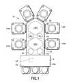
- FIG. 1illustrates a schematic plan view of a substrate processing apparatus in accordance with an exemplary embodiment
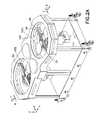
- FIGS. 2A-2Crespectively illustrate a schematic top perspective view, a side cross-sectional view and a schematic bottom perspective view of a transport chamber section in accordance with an exemplary embodiment
- FIGS. 3A-3Crespectively show a schematic perspective view, a schematic partial perspective view and a side cross-sectional view of a transport apparatus in accordance with an exemplary embodiment
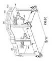
- FIGS. 4A-4Crespectively illustrate a schematic perspective view, a schematic partial perspective view and a side cross-sectional view of a transport apparatus in accordance with an exemplary embodiment
- FIG. 5shows a schematic perspective view of a drive section in accordance with an exemplary embodiment
- FIG. 6illustrates a partial perspective view of a stator segment and rotors of the drive section of FIG. 5 ;
- FIGS. 7A-7Crespectively illustrate a schematic top perspective view, a side cross-sectional view and a schematic bottom perspective view of a transport chamber section in accordance with an exemplary embodiment
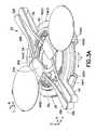
- FIGS. 8A-8Crespectively show a schematic perspective view, a schematic partial perspective view and a side cross-sectional view of a transport apparatus in accordance with an exemplary embodiment
- FIG. 9illustrates a cross section of a representative rotor of the transport apparatus of FIG. 8A ;
- FIG. 10shows a portion of a motor in accordance with an exemplary embodiment
- FIG. 11illustrates a transport apparatus, a portion of which is shown in FIG. 9 , in accordance with an exemplary embodiment
- FIGS. 12A-12Crespectively show a schematic top perspective view, a side cross-sectional view and a bottom perspective view of a transport apparatus in accordance with an exemplary embodiment
- FIGS. 13A-13Crespectively show a schematic perspective view, a schematic partial perspective view and a side cross-sectional view of a transport apparatus in accordance with an exemplary embodiment
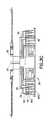
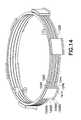
- FIG. 14shows a schematic perspective view of a drive section in accordance with an exemplary embodiment
- FIG. 15is a schematic plan view of a substrate processing tool and carriers connected thereto in accordance with other exemplary embodiments.
- FIG. 16is a schematic plan view of a substrate processing tool and carriers connected thereto in accordance with other exemplary embodiments.
- FIG. 1there is shown a schematic plan view of a substrate processing apparatus incorporating features in accordance with an exemplary embodiment.
- a substrate processing apparatusincorporating features in accordance with an exemplary embodiment.
- the exemplary embodimentswill be described with reference to the embodiments shown in the drawings, it should be understood that the exemplary embodiments can be embodied in many alternate forms.
- any suitable size, shape or type of elements or materialscould be used.
- the processing apparatus 10in the exemplary embodiment illustrated in FIG. 1 , has a representative configuration, and in alternate embodiments, the apparatus may have any other desired configuration.
- the process apparatusis shown as a cluster tool for exemplary purposes only. It should be realized that that the exemplary embodiments apply equally well to any other suitable type of substrate processing system having transport apparatus including, but not limited to, linear processing systems. Examples of suitable processing systems in which the exemplary embodiments can be incorporated include but are not limited to U.S. patent application Ser. No. 11/442,511, entitled “Linearly distributed Semiconductor Workpiece Processing Tool,” filed May 26, 2006, the disclosure of which is incorporated by reference herein in its entirety.
- the exemplary processing apparatus 10 shown in FIG. 1may generally have an interface section 12 , that for example may be referred to as a front end module (as may be realized the reference frame used for this description is exemplary, and in alternate embodiments any desired reference frame may be used, for example the interface section may be located at the back, or sides of the apparatus).
- the apparatus 10may include a processing section 14 , that is connected to the interface section 12 .
- the interface section 12may be arranged (for example may have one or more load ports 12 L, and suitable transfer system 12 T, such as may be located in a suitably environmentally controlled module 12 M) to allow substrates, or other desired workpieces, to be loaded and unloaded from the apparatus 10 .
- the transfer system 12 T, of the interface section 12may transfer substrates for example between cassettes at the loading stations of the interface section and the processing section 14 , within the suitably controlled environment of the module 12 M.
- the processing section 14 in the exemplary embodimentmay generally have a number of transport chambers 14 T 1 , 14 T 2 (two transport chambers are shown in FIG. 1 for example purposes, though in alternate embodiments there may be more or less than two chambers), and a number of processing modules 14 M communicably connected to the transport chambers 14 T 1 , 14 T 2 .
- the processing modules 14 Mmay be configured to perform any desired processes on the substrates, such as for example, thin film processes that use a vacuum such as plasma etch or other etching processes, chemical vapor deposition (CVD), plasma vapor deposition (PVD), implantation such as ion implantation, metrology, rapid thermal processing (RTP), dry strip atomic layer deposition (ALD), oxidation/diffusion, forming of nitrides, vacuum lithography, epitaxy (EPI), wire bonder and evaporation or other thin film processes that use vacuum pressures or any other desired processes.
- the transport chambers 14 T 1 , 14 T 2may be arranged to hold an isolatable atmosphere capable of being isolated from the exterior atmosphere.
- the transport chambers 14 T 1 , 14 T 2may be capable of holding a vacuum atmosphere (though in alternate embodiments the transport chamber may hold any other desired isolated atmosphere such as an inert gas N2, Ar, etc.).
- the transport chambers 14 T 1 , 14 T 2in the exemplary embodiment may thus include suitable vacuum pumping system and vent system as will be described further below.
- the transport chamber(s) 14 T 1 , 14 T 2of the processing section 14 , may communicate with the interface section 12 via loadlocks(s) 16 .
- the process module(s) 14 Mmay be isolated from the transport chamber(s) 14 T 1 , 14 T 2 by suitable slot valves.
- the transport chambers 14 T 1 , 14 T 2may be capable of being isolated from each other.
- the transport chambers 14 T 1 , 14 T 2may be serially arranged, relative to the front or interface section 12 of the apparatus, and intermediate loadlocks 14 LL may be disposed as shown in FIG. 1 between the transport chambers 14 T 1 , 14 T 2 .
- the transport chambers 14 T 1 , 14 T 2may be capable of holding different isolated atmospheres, such as different levels of vacuum, and hence the process modules 14 M connected to the respective transport chambers 14 T 1 , 14 T 2 may be capable of performing different processes having different base pressures.
- the transport chambers 14 T 1 , 14 T 2may not have different atmospheres.
- the intermediate chambers 14 LL, between transfer chambers 14 T 1 , 14 T 2may also be configured as substrate buffers, aligners or metrology sections.
- each transport chamber 14 T 1 , 14 T 2may have a transport apparatus 20 , 22 mounted respectively therein.
- transport apparatus 20located in chamber 14 T 1 , is capable of transporting substrates between loadlocks 16 and processing modules 14 M, or intermediate loadlocks 14 LL connected to transport chamber 14 T 1
- transport apparatus 22is capable of transporting substrates between the intermediate loadlocks 14 LL and processing modules connected to the transport chamber 14 T 2 .
- the transport chamber(s) 14 T 1 , 14 T 2 of the processing sectionmay have more or fewer transport apparatus.
- the substrate processing apparatus 10 and its subsectionse.g.
- interface section 12 , processing section 14 , transport apparatus 20 , 22may be suitably configured to process any desired substrate including, but not limited to, 200 mm, 300 mm, 450 mm or any other desired diameter substrate (such as may be used in semiconductor manufacture), reticle or pellicle, and flat panels (such as may be used in flat panel display manufacture).
- any desired substrateincluding, but not limited to, 200 mm, 300 mm, 450 mm or any other desired diameter substrate (such as may be used in semiconductor manufacture), reticle or pellicle, and flat panels (such as may be used in flat panel display manufacture).
- FIGS. 2A-2Cthere is shown respectively schematic top and bottom perspective and side cross-sectional views of the transport chamber section 14 T (in FIG. 2A closure elements are omitted so that chamber interior details are visible).
- the transport chamber 14 T 1 , 14 T 2 sectionmay include a transport system, in the exemplary embodiment, apparatus 20 , 22 , to transport substrates through the transport chambers 14 T 1 , 14 T 2 to and from loadlocks 16 (see also FIG. 1 ) and the processing modules 14 M of the processing section 14 .
- the transport apparatus 20 , 22are generally articulated, or movably jointed arms powered by rotary drives with a number of independent axes of rotation to generate desired radial (R) and rotational (T) motion (for example indicated respectively by arrows R, T in FIG. 2A ) of transport apparatus end effector(s) as will be described in greater detail below.
- the rotary driveshave, what may be referred to for purposes of the description as ring motors with coils that may be incorporated within the walls defining their respective transport chambers 14 T 1 , 14 T 2 , thereby isolating the coils from chamber atmosphere as will also be described further below.
- the arrangement of the drive section motorsenables the bottom surface of the transport chamber to be free or otherwise accessible for mounting and interface of for example a vacuum pumping system 100 (see FIGS. 2B , 2 C) or other desired systems.
- the arms and drive of the transport apparatus armsmay be magnetically levitated, and centered for example with self bearing motors eliminating or substantially reducing potential for particle generation within the chamber atmosphere.
- the transport apparatus 20 , 22 in the respective transport chambers 14 T 1 , 14 T 2may be different from each other.
- transport apparatus 20may have what may be referred to, for description purposes, as a bi-symmetric arm arrangement, and transport apparatus 22 may have a symmetric arm arrangement.
- the substrate transport apparatusmay have any other desired arrangement, such as for example a scara arrangement.
- the transport apparatus in the transport chambersmay be similar. Suitable examples of transport arms can be found in U.S. patent application Ser. No. 12/117,355, entitled “Substrate Transport Apparatus” filed on May 8, 2008, the disclosure of which is incorporated by reference herein in its entirety.
- transport apparatus 20may have a bi-symmetric arm arrangement, having for example two arm assemblies 24 , 26 (though in alternate embodiments there may be more or fewer arm assemblies).
- the arm assemblies 24 , 26may be substantially similar to each other, and are arranged in the exemplary embodiment generally opposing each other as seen best in FIG. 3A so that the arms extend and retract in substantially opposite directions.
- Arm 24may have one (or more) end effectors 24 E (capable of holding a desired number of substrates thereon) and a pair of arm links 30 R, 30 L on which the end effector 24 E is movably mounted (arm assembly 26 is similar and hence, the arm assemblies will be described below with specific reference to arm assembly 24 for illustrative purposes except where noted).
- arm assembly 26is similar and hence, the arm assemblies will be described below with specific reference to arm assembly 24 for illustrative purposes except where noted).
- the bent shape of the arm links 30 R, 30 Lis exemplary and in alternate embodiments the arm links may have any suitable shape including, but not limited to, straight and arcuate.
- One end of the arm links 30 R, 30 Lmay be pivotally mounted at pivots 32 L, 32 R to respective base members 34 , 36 , in any suitable manner.
- the other opposite end of the arm links 30 R, 30 Lmay be pivotally joined to the end effector 24 E at wrist joint(s) 35 R, 35 L.
- the arm links 30 R, 30 Lmay be pivotally joined to the base members and end effector at any suitable point along the arm links.
- both arm assemblies 24 , 26are mounted or otherwise joined to common base members 34 , 36 , and via the base members 34 , 36 to the drive section 28 .
- the drive section 28may have nested motor(s) providing two independent axes of rotation (T 1 , T 2 ) and hence two degrees of freedom motion of the arm assemblies 24 , 26 (R, T).
- the bi-symmetric geometry of the arm links of the arm assemblies 24 , 26effects general decoupling of R motion between arm assemblies (e.g. extension and retraction (R movement) of one arm assembly, such as effected by counter rotation of axes of rotation T 1 , T 2 , from a battery or retracted position causes little corresponding R movement of the other arm assembly at the battery position).
- the arm assembliesmay be independently coupled to the drive section so each arm assembly may be individually moveable in the R direction.
- the base members 34 , 36may have any desired shape capable of coupling the outer pivot joints 32 L, 32 R of the arm links 30 L, 30 R to the rotors of the drive section motors (the configuration of the base members 34 , 36 shown in FIGS. 3A-3B is merely exemplary and in alternate embodiments, the base members may have any other suitable configuration).
- the drive section 28may have nested ring motors 40 , 42 (defining independent axes of rotation T 1 , T 2 ), and the base members 34 , 36 may be respectively connected to the corresponding drive motors 40 , 42 in a substantially shaftless or hubless manner.
- each base member 34 , 36may have a general hoop section 34 R, 36 R and extensions 34 E, 36 E depending therefrom to the corresponding pivot joints 32 L, 32 R of the arm assemblies 24 , 26 .
- the base membersmay be substantially flat, such as a sheet metal stamping, though in alternate embodiments, the base member may be formed in any other desired manner from any suitable materials.
- the hoop sections 34 R, 36 Rwhich may be closed or open, are respectively joined to the corresponding ring rotors of motors 40 , 42 .
- the hoop sections of the base membersmay be fastened to the motor rotors in any desired manner (e.g. mechanical fasteners, chemical bonding, etc.).
- the motor rotorsmay be otherwise integrated to the base members (for example the base member may have an integrally formed ring of magnetic material configured so as to be capable of operating as a motor rotor).
- the hoop sections of the base membersmay extend around and be fastened to as long a section of the rotor circumference as desired.
- the nested motors 40 , 42may be located concentrically (their respective axes of rotation T 1 , T 2 being coaxial) so that one of the motors surrounds the other one of the motors, and the base members 34 , 36 are configured to allow rotation thereof without interference with each other.
- the base members and coupling between base members and drive section T 1 and T 2 motorsmay be configured in any other desired manner and may include one or more shaft(s) or hub(s).
- the motors 40 , 42 of drive section 28are integrated into the bottom wall 14 B defining the transport chamber(s) 14 T 1 , 14 T 2 .
- the drive section motorsmay be integrated into any other walls bounding the transport chambers, such as side wall(s) or top wall(s).
- the ring motors 40 , 42 of the drive sectionmay be arranged to define a clean or substantially free space 44 (unencumbered with drive system components) interior to the motors for locating or housing other components such as a vacuum pump system 100 (see for example FIGS. 2B and 3B ) and associated components for atmosphere control (e.g.
- FIG. 5there is shown a schematic perspective view of a drive section 128 substantially similar to drive section 28 (drive section 128 in the exemplary embodiment illustrated may have motors to define four independent axes of rotation T 1 -T 4 , and drive section 28 , as noted before, may have two independent axes of rotation).
- the concentrically positioned motors 40 , 42 (T 1 , T 2 ) of drive section 28may be substantially similar.
- the drive sectionmay include different types of motors.
- the motors 40 , 42may be synchronous motors such as brushless DC motors. Suitable examples of brushless DC motors are described in U.S. patent application Ser. No. 11/769,688, filed Jun. 27, 2007, U.S. patent application Ser. No. 11/769,651, filed Jun. 27, 2007, and U.S. patent application Ser. No. 12/163,996, filed Jun. 27, 2008 all incorporated by reference herein in their entirety. As noted before, in the exemplary embodiment motors 40 , 42 may be similar and hence will be described below with specific reference to motor 40 , except as otherwise noted.
- the motor windingsmay be disposed in the stator 40 S, and the rotor 40 R may have permanent magnets arranged circumferentially in an alternating pole sequence at a desired pitch.
- the rotor 40 Rmay have ferromagnetic backing (or backing of any other suitable magnetic materials) for the permanent magnets.
- the stator 40 Smay be arranged in stator segments 40 S 1 - 40 S 4 , such as for example four stator segments as can be seen best in FIG. 3A (see also FIG. 5 , reference numerals 140 S 1 - 140 S 4 ), though in alternate embodiments there may be more or fewer stator segments.
- the stator segments 40 S 1 - 40 S 4may be geometrically offset (e.g.
- stator windings and rotor magnetsmay be capable of generating tangential forces, in the direction of arrow T in FIGS. 3A and 5 , and/or radial forces (r) (see FIG. 5 ) to provide substantially independently controllable torque (T 1 , T 2 ) and self bearing centering forces.
- the windings of one or more of the stator segments 40 S 1 - 40 S 4may be coupled to each other to form winding set(s) independently controllable and in the exemplary embodiment the motor 40 may have at least two independently controllable winding sets (though in alternate embodiments there may be more or fewer winding sets).
- Commutation of the windings in segments 40 S 1 - 40 S 4 to provide the desired torque and independent rotor centeringmay be controlled via suitable algorithms in a controller (not shown). Examples of suitable commutation programs for commutating the windings in stator segments 40 S 1 - 40 S 4 are described in U.S. patent application Ser. Nos. 11/769,688 and 11/769,651 previously incorporated by reference.
- rotor centering forcese.g. radial and or tangential forces may be controlled to effect rotor 40 R, 42 R, and hence arm assembly 24 , 26 , motion in the X, Y directions (e.g.
- the rotormay have suitable passive centering such as for example, mechanical contact (e.g. shafts, bearings, etc.) or magnetic non-contact centering.
- the motors 40 , 42which may be concentrically adjoining, may be configured to use or share common or combined stator segments located for example between the rotors.
- FIG. 6which illustrates a partial perspective view of a stator segment, such as for example, stator segment 140 S 1 , and rotors 142 R, 140 R of drive section 128 .
- Stator segment 140 S 1 and rotor sections 140 R, 142 Rare representative of a suitable stator segment.
- Rotors 40 R, 42 R and stator segments 40 S 1 of drive section 28are similar. As seen in FIG.
- the stator segment 140 S 1may have a core section 140 C, made for example of suitable magnetic material.
- the configuration of the core section 140 C shown in FIG. 6is exemplary, and in alternate embodiments, the core section may have any desired configuration.
- the core section 140 Cmay include winding slots or teeth, for both windings 140 W, 142 W of both motors 140 , 142 which are similar to motors 40 , 42 (see FIG. 3B ).
- the core section 140 Cmay be of unitary construction, though in alternate embodiments, the core section may be a combined assembly.
- the winding slots 140 W, 142 Wmay be disposed respectively on opposite sides of the core 140 C to face their corresponding motor rotors 140 R, 142 R.
- the winding slots 140 W, 142 W in the core 140 Care illustrated as being substantially symmetrical for example purposes only, and in alternate embodiments, the winding slots in the core for each motor stator may be different (such as corresponding to the configuration and operating parameters of the given motor). In other alternate embodiments, one or more slots or gaps (for example extending concentrically with the faces of the core) may be formed in the core section in order to provide a desired magnetic configuration to the core. Suitable examples of stator segments are described in U.S. patent application Ser. No. 12/163,993, filed Jun. 27, 2008 incorporated by reference herein in its entirety. As may be realized, and seen in FIG. 6 , the rotors 140 R, 142 R (similar to rotor 40 R, 42 R shown in FIG.
- the rotors 140 R, 142 Rmay have the permanent magnets positioned to face the corresponding windings on the combined core section 140 C located in between the rotors 140 R, 142 R.
- the permanent magnets on the respective rotors 140 R, 142 Rmay be facing each other (as may be realized, the gap between rotors may be sized and/or suitable materials may be positioned within the chamber wall to avoid magnetic influence between rotors).
- the permanent magnetsmay have any suitable orientations with respect to each other.
- the motor stators and rotorsmay have any other suitable configuration.
- the motors 40 , 42may be capable of generating lift forces without contact (e.g. Z forces, see FIG. 3A ).
- the rotor magnets and stator coremay be so positioned to generate passive lift, stably holding the rotor, and hence the arm assemblies in the Z direction via, for example, magnetic levitation.
- the configuration of the stator segments 40 S 1 - 40 S 4 and rotors 40 R, 42 R of motors 40 , 42may be established to generate desired stiffness of the rotor(s) 40 R, 42 R in the Z direction and rotor stiffness for pitch and roll (respectively rotation of the rotor about Y and Z axes).
- the drive sectionsuch as drive section 28
- the drive sectionmay be capable of providing Z axes motion to the arm assemblies.
- the stator segments 40 S 1 - 40 S 4may be positioned on an actuable platform or carriage (not shown) having controllable Z travel. As maybe realized the actuable platform or carriage may be driven by any suitable motor including, but not limited to, self bearing actuators and screw drives.
- a suitable sealmay be provided between the actuable platform and the internal volume of the transport chamber to prevent particulates that may be generated from the Z-drive from entering the transport chamber.
- the motor rotor and/or statormay be configured to generate active Z forces enabling Z travel of the rotor(s) 40 R, 42 R, relative to the stator(s) 40 S 1 - 40 S 4 , and hence of the arm assemblies 24 , 26 within the transport chamber(s) 14 T 1 , 14 T 2 .
- the drive section 28may not be capable of generating Z-travel of the arm assemblies.
- stator segments 140 S 1may have anti-cogging features 140 G 1 , 140 G 2 , 142 G 1 , 142 G 2 .
- the combined stator segment 140 S 1may have anti-cogging features for both rotors 140 R, 142 R of motors 140 , 142 .
- each stator segmentsuch as segments 40 S 1 - 40 S 4
- the combined or collective effect of the anti-cogging featuressimilar to features 140 G 1 , 140 G 2 , 142 G 1 , 142 G 2 ) of some or all the stator segments 40 S 1 - 40 S 4 eliminates or reduces motor cogging to pre-determined levels, for accurate substrate positioning with the transport apparatus, in at least the Z direction, the radial (r) direction and rotationally (for the T 1 , T 2 axes) during motor operation.
- a suitable example of anti-cogging features on motor stator segmentsis described in U.S. patent application Ser. No. 12/163,993 previously incorporated by reference.
- the motors 40 , 42may have suitable position feedback systems 50 , 52 .
- the position feedback systems 50 , 52may be non-invasive with respect to the isolated atmosphere in the transport chamber, as will be described below.
- the feedback system 50 , 52 for motors 40 , 42may be generally similar to the feedback system 150 , 152 shown in FIG. 6 .
- the feedback systems 150 , 152 for each rotormay be similar to each other and may generally incorporate sensors 150 A, 150 G, 1501 and target indexing to establish absolute and incremental rotational position, as well as radial or centered position of the rotor 140 R, 142 R.
- the sensors 150 A, 150 G, 1051may provide feedback information for any one or more of the absolute and incremental rotational position and the radial position.
- the sensors 150 A, 150 G, 1501may be electromagnetic sensors such as Hall effect sensor, or may be optical or other beam sensors.
- the sensorsmay be any suitable sensors, including but not limited to inductive sensors.
- the sensorsmay be located outside the chamber as will be described further below.
- the sensorsmay be located in any suitable position relative to the motors 40 , 42 .
- the rotor backingmay have target indexing or any other suitable positional scale located thereon, that is sensed or otherwise read by the corresponding sensors 150 A, 150 G, 150 I to establish the rotor position as noted above.
- sensors 150 Amay sense a corresponding target index track on the rotor backing indexed to establish absolute rotational position of the rotor 140 R.
- Sensors 150 Imay sense a corresponding target index track on the rotor backing indexed to establish incremental rotational position of the rotor
- sensor 150 Gmay sense a corresponding target track on the rotor backing to sense the radial gap position, and hence centering position of the rotor 140 R.
- sensorsthere may be more or fewer sensors (for example sensor data from one or more sensors may be used to establish more than one position parameter of the rotor).
- sensor datafrom one or more sensors may be used to establish more than one position parameter of the rotor.
- a suitable example of a position feedback sensor system 50 , 52is described in U.S. application Ser. No. 12/163,984, filed Jun. 27, 2008 incorporated by reference herein in its entirety.
- Sensors similar to sensors 150 A, 150 I, 150 Gmay be positioned as desired in predetermined locations with respect to the rotor(s) as will be described further below.
- the drive section 28may be integrated within the bottom wall 14 B of the transport chamber (see for example FIG. 2B ). As seen in FIGS. 2B-2C , the lower or exterior surface of the bottom wall is substantially free of drive section components.
- the motor stator 40 S, 42 S and feedback position system 50 , 52may be isolated from the interior atmosphere of the transport chamber 14 T 1 .
- the isolated motor stators 40 S, 42 S and feedback systems 50 , 52(as well as the rotors 40 R, 42 R within the isolated atmosphere) may be located, at least in part, within the SEMI specified height of the transport chamber. As seen best in FIGS.
- the stators and feedback system sensorsmay be located inside an isolation casing or cover 14 H that is mounted to the bottom wall 14 B of the chamber and has a wall 14 P that isolates the stators and feedback sensors within the cover 14 H from interior of the transport chamber 14 T 1 , 14 T 2 .
- the cover 14 Hmay be configured with housing channels for the stators and grooves for the rotors of the respective motors (for example, as shown in FIGS. 3B , 4 B) so that the stators and rotors are embedded at least impart in what may be referred to for description purposes, as the peripheral wall of the transport chamber.
- the cover 14 Hmay be segmented into cover segments 14 H 1 - 14 H 4 (see FIG. 3A and also FIG. 5 ) generally conforming to the stator segments 40 S 1 - 40 S 4 .
- the cover segmentsmay be similar to each other, and will be described further below with specific reference to cover segment 14 H 1 .
- the cover segment 14 H 1may be of unitary construction and be made of any suitable material (such as aluminum or other non-magnetic material). In alternate embodiments the cover segment 14 H 1 may not have a unitary construction.
- the cover segment 14 H 1may be shaped to form a flange 14 F (see e.g. FIG.
- the cover segment 14 Hin the exemplary embodiment shown in FIG. 5 , may have recess sections 14 SO, 14 SI for the motor stator segments (e.g. stator segments 40 S 1 - 40 S 4 may be located inside recess 14 SO of the cover segment).
- FIG. 5illustrates a portion of cover segment 14 H 1 , which shows stator segment 140 S 1 (similar to stator segment 40 S 1 ) located inside cover recess 14 SO.
- the wall 14 P of the coveris located between the stator and interior of the transport chamber and thus isolates the stator from the isolated atmosphere inside the transport chamber.
- the cover segmentmay also include recess sections 14 FI, 14 FN, 14 FO as shown for sensors, such as sensors 150 A, 105 G, 150 I of the feedback systems 50 , 52 (see also FIG. 6 which shows sensor portions of feedback systems 150 , 152 respectively located inside corresponding recess sections 14 FN, 14 FO of the cover segment.
- recess sections of the cover segment 14 Hposition the stator segments and position feedback systems, located therein, within the bottom wall of the transport chamber yet isolated (by the cover segment wall located in between) from the atmosphere of the transport chamber.
- Sensors 150 A, 150 I, 150 Gmay be capable of sensing the target indexes through the cover wall 14 P.
- the cover wall 14 Pmay include transparent sections or windows allowing sensor reading while maintaining isolation between chamber interior and sensor.
- the stator segments 14 S 1 - 14 S 4 and feedback system sensors 50 , 52may be mounted to their respective cover segment 14 H 1 - 14 H 4 so that the covered stator segment and corresponding feedback system portion may be installed and removed from the transport chamber as a unit module.
- each of the stator cover, stators and feedback system sensorsmay be individually installed and removed.
- the bottom wall 14 B of the transport chamber(s) 14 T 1 , 14 T 2may have openings 200 for admitting installation of the cover segments 14 H 1 - 14 H 4 into the bottom wall 14 B.
- the openingsmay be located on any suitable side of the transport chamber(s) 14 T 1 , 14 T 2 for the installation of the cover segments 14 H 1 - 14 H 4 .
- the vacuum pump (and/or vent) system 100may be mounted to the exterior surface of the bottom wall 14 B. The pump system 100 may access the chamber interior through the access space 44 defined within the drive section as described before.
- apparatus 22may have a symmetric arm arrangement with, in the example shown, two symmetrical arm assemblies 22 U, 22 L facing substantially the same direction.
- the arm assemblies 22 U, 22 Lmay be coupled to a drive section 128 with motor arranged to generate four rotation axes (T 1 , T 2 , T 3 , T 4 ) as shown for example in FIG. 5 .
- motion of the arm assemblies 22 U, 22 Lmay be independently controlled. In other exemplary embodiments the motion of the arm assemblies may be controlled in any suitable manner.
- Arm assemblies 22 U, 22 Lare substantially similar to each other, and to arm assemblies 24 , 26 described previously.
- the arm assemblies 22 U, 22 Lmay not be similar to each other. In this example, similar features are similarly numbered.
- the lower arm assembly 22 Lmay have symmetric arm links 130 LR, 130 LL linking the respective end effector 124 E to base members 134 , 136 .
- the base members 134 , 136may be coupled motors 140 , 142 of drive section 128 which generate rotation axes T 1 , T 2 (for T and R motion of arm 22 L).
- Motors 140 , 142 , 144 , 146may be substantially similar to each other, and to motors of drive section 28 as noted before. In alternate embodiments, one or more of the motors 140 , 142 , 144 , 146 may be different from each other.
- the upper arm assemblymay have symmetric arm links 130 UL, 130 UR linking the respective end effector 124 E to base arms 122 L, 122 R.
- the base arm links 122 L, 122 Rmay be fixed respectively to base members 164 , 166 that in turn are respectively coupled to corresponding motors 144 , 146 generating rotation axes T 3 , T 4 (for T and R motion of arm 22 U).
- Base members 164 , 166may be generally similar to base members 34 , 36 , but may have extension members 164 E, 166 E extending generally upwards to mate with the base arms 122 R, 122 L.
- the extension members 164 E, 166 Emay be coaxial, and may be offset vertically from the motor rotors as desired to maintain a substantially open area within the drive section 128 similar to access area 44 shown in FIG. 3B .
- the base membersmay include rotors 144 R, 146 R as can be seen in FIG. 4B .
- the rotors 144 R, 146 Rmay be mounted to the base members 164 , 166 in substantially the same manner and be substantially similar to rotors 140 R, 142 R described above with respect to FIG. 6 .
- the arm assemblies 22 U, 22 L and drive section 128may be mated to, for example, the bottom wall 14 B of the transport chamber in a manner substantially similar to that of arm assembly 24 , 26 and drive section 28 described before. In alternate embodiments, the arm assemblies 22 U, 22 L and drive section 128 maybe mated to any suitable wall of the transport chamber in any suitable manner.
- Transport apparatus 722 , 723 in the transport chamber 714 T 1 , 714 T 2may include bi-symmetric arm assemblies 724 , 726 and symmetric arm assemblies 722 U, 722 L.
- the arm assemblies 724 , 726 , 722 U, 722 Lare powered by their respective drive sections 728 , 728 U, 728 L which may be incorporated into the peripheral side walls 714 W of the transport chamber.
- drive sections 728 , 728 U, 728 Lmay be embedded within the wall 714 W or mounted on a surface of the wall 714 W and may or may not be isolated from an internal atmosphere of the transport chamber(s) 714 T 1 , 714 T 2 .
- bi-symmetric transport apparatus 723is shown.
- the transport apparatus 723may be substantially similar to transport 20 described above with respect to, for example, FIGS. 2A-2C except as otherwise noted.
- the arm links 730 L, 730 R of arm assemblies 724 , 726may be pivotally linked to base members 734 , 736 respectively.
- the base members 734 , 736may be coupled to rotor hoops 740 R, 742 R, of motors of drive section 728 (for generating T 1 , T 2 rotation).
- the rotor hoops 740 R, 742 Rmay extend exterior of the pivots 732 L, 732 R of the arm links 730 L, 730 R, such that the base members 734 , 736 may depend from the interior face of the rotor hoops.
- the base membersmay depend from any suitable face (e.g. including top, bottom and exterior face) of the rotor hoops.
- the rotor hoops 740 R, 742 Rmay be arranged in a general stacked configuration. In alternate embodiments the rotor hoops may have any suitable spatial relationship with respect to each other.
- the bi-symmetric geometry of the arm links of the arm assemblies 724 , 726effects general decoupling of R motion between arm assemblies (e.g. extension and retraction (R movement) of one arm assembly, such as effected by counter rotation of axes of rotation T 1 , T 2 , from a battery or retracted position causes little corresponding R movement of the other arm assembly at the battery position).
- each of the arm links of the two arms 724 , 726may be independently coupled to its own respective motor so each arm assembly may be individually moveable in the R direction.
- the rotor hoops 740 R, 742 Rmay be generally similar to rotors 40 R, 42 R described previously.
- FIG. 9a cross section of a representative rotor hoop 742 R is shown in greater detail.
- the rotor hoop 742 Rmay generally include permanent magnets 742 M mounted on ferromagnetic backing ring 742 B, and sensor target tracks 742 T suitably indexed for rotor position determination.
- the permanent magnets 742 M and sensor tracks 742 Tare located to face outwards. In alternate embodiments the permanent magnets and sensor tracks may face in any suitable direction relative to the rotor hoop.
- the rotor hoop 742 Rmay be an assembly, with the rotor backing 742 B and permanent magnets 742 M mounted on a hoop support section 742 H 1 , and the sensor track 742 T mounted on hoop support section 742 H 2 that are connected to form motor hoop 742 R using suitable fasteners.
- the hoop support sections 742 H 1 , 742 H 2may be joined together in any suitable manner including but not limited to any suitable mechanical or chemical fasteners.
- the hoop support sections 741 H 1 , 742 H 2may be formed from any suitable material such as non-magnetic metal including, but not limited to, for example, aluminum alloys. As seen best in FIG.
- the motor stators 740 S, 742 Smay be arranged in any suitable number of stator segments (six are shown for example purposes) similar to those described before (with respect to e.g. FIGS. 5 and 6 ), that may be housed in isolating casings 714 HU, 714 HL in combination for example with sensors of the position feedback system. It is noted that in FIG. 10 two sets of motor stators 710 S 1 , 740 S 2 are shown for exemplary purposes only. As may be realized from FIG. 10 , the transport may have any suitable number of stator sets arranged in, for example, a generally stacked configuration.
- FIG. 11shows transport apparatus 722 with symmetric arm assemblies 722 U, 722 L connected to respective rotor hoops 740 R, 742 R, 744 R, 746 R (for generating axes of rotation T 1 , T 2 , T 3 , T 4 ) of drive section 728 U, 728 L.
- the drive section 728 L, 728 Umay be arranged with motors 740 , 742 located under the transport arm assemblies 722 L, 722 U, and motors 744 , 746 located above the arm assemblies so that as the arms are extended and retracted they pass between the motors 740 , 742 and 744 , 746 .
- the motors 744 , 746 of the upper drive section 728 U, (T 3 , T 4 rotation)may power the upper arm assembly 722 U
- the motors 740 , 742 of the lower drive section 728 L (T 1 , T 2 rotation)may power the lower arm assembly 722 L
- the upper rotor hoops 744 R, 746 Rmay also be driven by stators 740 S as shown in FIG. 10 .
- Each of the stators 740 Smay be modular units capable of being separately installed or removed from the transport chamber 714 T. In alternate embodiments multiple stators may be joined to or have a unitary construction with each other, such as for example, stators that are arranged adjacent each other (e.g.
- stators 740 S 1 , 740 S 2may be joined so they can be removed or installed as a unit.
- access slots 714 SU, 714 SLmay be formed into the upper and/or lower surfaces of the peripheral chamber walls 714 W for installation of the respective stator casings 714 HU, 714 HL for the upper and lower drive sections 728 U, 728 L.
- Transport chamber section 1114 Tmay be similar to transport chamber section 714 T except as otherwise noted.
- Section 1114 Tmay include transport apparatus with arm assemblies 1122 U, 1122 L and 1124 , 1126 .
- Arm assemblies 1124 and 1126are substantially similar to arm assemblies 724 , 726 , described before and shown in FIG. 7A , and are coupled to drive section 1128 , substantially similar to drive section 728 described previously.
- arm assemblies 1122 U, 1122 Lare generally similar to arm assemblies 722 U, 722 L and are connected to drive section 1228 that has motors 1240 , 1242 , 1244 , 1246 to generate rotation about axes T 1 , T 2 , T 3 , T 4 ; see also FIG. 12D ).
- the motors 1240 , 1242 , 1244 , 1246 of the drive section 1228are in a generally stacked configuration and are all located on one side of (e.g. under) the arm assemblies 1122 U, 1122 L.
- arm assembly 1122 Umay be coupled to rotor hoops 1244 R, 1246 R by articulated bridge section 1123 as seen best in FIG. 13A .
- the articulated bridge section 1123includes a first bridge section 1131 and a second bridge section 1130 .
- the first bridge sectionincludes an upper base member extension 1132 EU and lower base member extension 1132 EL joined together by shaft 1131 S.
- the second base member section 1130includes an upper base member extension 1134 EU and a lower base member extension 1134 EL joined together by shaft 1130 S.
- the bridge sections 1131 , 1130are pivotally joined to each other by their respective shaft sections 1131 S, 1130 S.
- the shaft sections 1131 S, 1130 Sare concentrically located such that shaft 1131 S passes through or within shaft 1130 S.
- the articulated bridge sections 1131 , 1130may be joined to each such that they are axially fixed (relative movement of the shafts) with respect to each other.
- arm assembly 1122 Lmay be coupled to rotor hoops 1240 R, 1242 R while arm assembly 1122 U is coupled to rotor hoops 1244 R, 1246 R.
- arm link 1122 LR of arm 1122 Lmay be pivotally coupled to a respective end effector 24 E at one end and pivotally coupled to base member 1132 BU of rotor 1240 R at the other opposite end.
- the other arm link 1122 LL of arm 1122 Lmay be pivotally coupled to the respective end effector 24 E at one end and pivotally coupled to base member 1134 BU of rotor 1242 R at the other opposite end.
- the arm link 1122 UR of arm 1122 Umay be pivotally coupled to a respective end effector at one end and pivotally coupled at the other opposite end to the base member extension 1132 EU of the bridge section 1123 .
- the other arm link 1122 UL of arm 1122 Uis pivotally coupled to the respective end effector at one end and pivotally coupled at the other end to the base member extension 1134 EU of the bridge section 1130 .
- the arm assembliesmay be connected to the rotor hoops in any other desired manner.
- the end effectorsare extended and retracted above the rotor hoops but in alternate embodiments the transport arms can be configured so that the end effectors pass below the rotor hoops during extension and retraction.
- stators 1240 S, 1242 S, 1244 S, 1246 Sare provided and may be arranged in stator segments (six are shown for example purposes) similar to those described before (with respect to e.g. FIGS. 5 and 6 ) for driving their respective rotors 1240 R, 1242 R, 1244 R, 1246 R.
- the stators 1240 S, 1242 S, 1244 S, 1246 Smay be substantially similar to each other and to those described above with respect to, for example, FIG. 10 .
- the statorsmay be housed in isolating casings 1414 in combination for example with sensors of the position feedback system in a manner substantially similar to that described above.
- access slots 1414 Smay be formed into the lower surfaces of the peripheral chamber walls for installation of the respective stator casings 1414 in a manner substantially similar to that described above with respect to e.g. FIG. 7C .
- the tool 2002may have processing modules 2006 , 2006 A, and front end module (FEM) 2004 with a desired controlled atmosphere (e.g. inert gas or very clean air).
- FEMfront end module
- One or more of the process modules 2006may be connected to the FEM so that the FEM transport robot 2004 R may pick/place substrates in the process module.
- Process modules 2006 , 2006 A(though one process module is shown in alternate embodiments a stack of process modules may be joined to the FEM or to each of the one or more transfer modules) may share a common atmosphere with the FEM 2004 .
- FEM 2004may have a loading interface or load port, for loading and interfacing a carrier 2100 to the tool in an integral manner similar to that described previously.
- the FEM transport robot 2004 R in the exemplary embodimentis shown as a SCARA robot that may pick/place substrates directly between carrier 2100 and one or more process module(s) 2006 through a clean tunnel substantially similar to that described in U.S. patent application Ser. No. 12/123,391 filed on May 19, 2008, the disclosure of which is incorporated herein by reference in its entirety.
- the SCARA robot 2004 Rmay have an upper arm 2004 RU, a forearm 2004 RF and an end effector 2004 RE rotatably connected to each other in series and nested drive motors substantially similar to those shown above with respect to, for exemplary purposes only, FIGS. 4A and 13A .
- the upper arm 2004 RU of the robot 2004 Rmay be connected to or be integral with a bridge spanning one of the rotors of the nested drive.
- the forearm 2004 RF and end effector 2004 REmay be slaved to the upper arm.
- the forearm 2004 RFmay be driven by one of the nested motors and the forearm 2004 RE may be slaved accordingly so that as the arm extends the forearm 2004 RE remains substantially longitudinally aligned with the path of extension.
- the drivemay have three nested motors such that each of the upper arm, forearm and end effector of the robot 2004 R are individually driven by a respective motor any suitable transmission members connecting the robot arm links to a respective one of the nested motors.
- the robot 2004 Rmay be configured with multiple arms, as described above with respect to FIGS. 4A and 13A so that the multiple arms provide multiple transport paths that are vertically stacked one above the other.
- the stacked transport pathsallow substrates to be fed into and removed from processing modules and/or carrier or transported through the tunnel 2005 while passing over each other in the same or different directions of transport.
- the vertically stacked transport pathsmay run from transport module 2008 to transport module 2008 A along the tunnel 2005 and/or from the transport modules to respective ones of the process modules 2006 and carrier(s) 2100 .
- the clean tunnel 2005 that is defined through the FEM interface 2010 into the carrier interior, and extends into the process modules 2006 , 2006 Amay be varied in length or configuration (for example in a manner similar to U.S. application Ser. No. 11/422,511, filed May 26, 2006; U.S. application Ser. No. 10/624,987, filed Jul. 22, 2003; U.S. application Ser. No. 10/962,787, filed Oct. 9, 2004; U.S. application Ser. No. 11/442,509, filed May 26, 2006 and U.S. application Ser. No. 11/441,711, filed May 26, 2006 all incorporated by reference herein in their entirety).
- transfer module(s) 2008may be connected to the FEM, so that the FEM robot may pick/place substrates into the transfer module.
- the location of the transfer module(s)is merely exemplary.
- the clean tunnelmay continue to extend from the FEM through the transfer module.
- More or fewer transfer module(s) 2008 , 2008 Amay be connected to each other (for example serially, such as shown in phantom in FIG. 15 ) to vary the length and configuration of the clean tunnel as desired.
- Process modules(similar to modules 2006 , 2006 A) may be joined to the clean tunnel so that substrates may be transferred through the clean tunnel, for example to/from the carrier 2010 and any desired process module, or between any desired process modules.
- the transfer module 2008may have a transport robot inside the module, for example to transport substrates to/from process modules 2006 A, or to an adjoining transfer module/chamber 2006 A.
- the transfer modulemay have no internal robot, the substrates being placed/picked there from by robots inside adjoining modules of the clean tunnel 2005 .
- the transfer modulemay have any suitable length and include any suitable substrate transfer apparatus.
- the transfer module(s) 2008 , 2008 A of the clean tunnel in tool 2002may share the common controlled (e.g. inert gas, very clean air) of the FEM.
- one or more of the transfer module(s) 2008 , 2008 Amay be configured as a load lock so that portions of the clean tunnel may hold different atmospheres (for example the clean tunnel portion defined within the FEM may have a N2 environment, and the portion within the module 2008 A may have a vacuum environment, transfer module 2008 may be a load lock capable of cycling substrates between the inert gas atmosphere in the FEM, and the vacuum atmosphere in module 2008 A).
- the carriermay be interfaced directly with a vacuum portion of a process tool as described in U.S. patent application Ser. No. 12/123,391.
- FIG. 16there is shown a plan view of another process tool 4002 in accordance with another exemplary embodiment.
- the tool 4002 in the exemplary embodiment shown in FIG. 16may have processing modules 4006 , 4006 A, and FEM 4004 with for example a vacuum atmosphere (or in alternate embodiments inert gas or very clean dry air).
- One or more of the process modules 4006(such as for example in vertically stacked or offset arrangement) may be connected to the vacuum FEM so that the vacuum transport robot 4004 R may pick/place substrate in the process module as shown in FIG. 16 and similar to embodiment shown in FIG. 15 .
- Process modules 4006 , 4006 amay share a common process vacuum with the loading section 4004 .
- FEM 4004may have a loading interface or load port, for loading and interfacing a carrier 4100 to the tool in an integral manner similar to that described previously.
- the vacuum transport robot 4004 R in the exemplary embodimentmay be substantially similar to that described above with respect to FIG. 15 and be configured to pick/place substrates directly between carrier 4100 and one or more process module(s) 4006 , 4006 A through a clean tunnel similar to that described in U.S. patent application Ser. No. 12/123,391, previously incorporated by reference.
- the clean tunnel 4005that is defined through the FEM interface 4010 , 4012 into the carrier interior and extends into the process modules 4006 , 4006 A may be varied in length or configuration.
- a substrate transport apparatusin a first aspect of the disclosed embodiment, includes a frame defining a chamber, at least one stator module embedded at least partly into a peripheral wall of the chamber, the at least one stator module defining an axis of rotation.
- the substrate transport apparatusfurther includes at least one rotor substantially concentrically disposed relative to the at least one stator module about the axis of rotation, the at least one rotor being configured to interface with the at least one stator module and being suspended by a respective one of the at least one stator module substantially without contact within the chamber.
- the substrate transport apparatusfurther includes at least one substrate transport arm connected to the at least one rotor and having at least one end effector configured to hold at least one substrate.
- the at least one rotoris magnetically suspended.
- the at least one rotormay be further configured to interface with the at least one stator module to generate movement along a linear axis perpendicular to a plane of the at least one stator module.
- the at least one stator moduleis at least two stator modules embedded at least partly into a peripheral wall of the chamber, the at least two stator modules being further arranged in a substantially nested configuration.
- the chamberis configured to hold an isolated atmosphere.
- the at least one stator moduleis located within a side or bottom of the peripheral wall.
- the at least one substrate transport armcomprises at least two individually rotatable transport arms, each being rotatable about a center of rotation of a respective one of the at least one rotor.
- the at least one substrate transport armcomprises two transport arms extendable in substantially opposite directions.
- the at least one substrate transport armcomprises two transport arms extendable in substantially the same direction.
- the substrate transport apparatusfurther includes a position feedback system comprising at least one sensor located within the at least one stator module and a sensor track located on the at least one rotor.
- a substrate transport apparatusin a second aspect of the disclosed embodiment, includes a housing having a peripheral wall and being configured to hold an isolated atmosphere, at least one stator module disposed within the peripheral wall so as to be sealed from the isolated atmosphere within the housing, at least one rotor disposed within the housing where each of the at least one rotor is suspended within the housing substantially without contact by a respective one of the at least one stator module, and at least one substrate transport arm connected to the at least one rotor.
- the at least one rotoris magnetically suspended.
- the at least one rotoris further configured to generate movement along a linear axis perpendicular to a plane of the at least one stator module.
- the at least one substrate transport armcomprises at least two transport arms extendable in substantially opposite directions.
- the at least one substrate transport armcomprises at least two transport arms extendable in substantially the same direction.
- the at least one stator moduleis located within a side or bottom of the peripheral wall.
- the at least one substrate transport armcomprises at least two individually rotatable transport arms, each being rotatable about a center of rotation of a respective one of the at least one rotor.
- the substrate transport apparatusfurther including a position feedback system comprising at least one sensor located within the at least one stator module and a sensor track located on the at least one rotor.
- a substrate transport apparatusin a third aspect of the disclosed embodiment, includes a frame forming a chamber having a peripheral wall, at least one stator module set at least partially disposed within the peripheral wall, at least one rotor suspended within the chamber by a respective one of the at least one stator module set substantially without contact, and at least one substrate transport arm connected to the at least one rotor.
- the chamberis configured to hold an isolated atmosphere.
- the at least one rotoris magnetically suspended.
- the at least one rotoris further configured to generate movement along a linear axis perpendicular to a plane of the at least one stator module.
- the at least one stator moduleis set at least disposed within a side or bottom of the peripheral wall.
- the at least one substrate transport armcomprises at least two substrate transport arms extendable in substantially opposite directions.
- the at least one substrate transport armcomprises at least two substrate transport arms extendable in substantially the same direction.
- the at least one substrate transport armcomprises at least two substrate transport arms, each being rotatable about a center of rotation of a respective one of the at least one rotor.
- the substrate transport apparatusfurther includes a position feedback system comprising at least one sensor located within the at least one stator module and a sensor track located on the at least one rotor.
Landscapes
- Engineering & Computer Science (AREA)
- Power Engineering (AREA)
- Physics & Mathematics (AREA)
- General Physics & Mathematics (AREA)
- Microelectronics & Electronic Packaging (AREA)
- Computer Hardware Design (AREA)
- Manufacturing & Machinery (AREA)
- Condensed Matter Physics & Semiconductors (AREA)
- Robotics (AREA)
- Mechanical Engineering (AREA)
- Electromagnetism (AREA)
- Combustion & Propulsion (AREA)
- Chemical & Material Sciences (AREA)
- Container, Conveyance, Adherence, Positioning, Of Wafer (AREA)
Abstract
Description
Claims (19)
Priority Applications (1)
| Application Number | Priority Date | Filing Date | Title |
|---|---|---|---|
| US13/567,812US8680803B2 (en) | 2007-07-17 | 2012-08-06 | Substrate processing apparatus with motors integral to chamber walls |
Applications Claiming Priority (4)
| Application Number | Priority Date | Filing Date | Title |
|---|---|---|---|
| US95033107P | 2007-07-17 | 2007-07-17 | |
| US12/175,278US8008884B2 (en) | 2007-07-17 | 2008-07-17 | Substrate processing apparatus with motors integral to chamber walls |
| US13/219,267US8237391B2 (en) | 2007-07-17 | 2011-08-26 | Substrate processing apparatus with motors integral to chamber walls |
| US13/567,812US8680803B2 (en) | 2007-07-17 | 2012-08-06 | Substrate processing apparatus with motors integral to chamber walls |
Related Parent Applications (1)
| Application Number | Title | Priority Date | Filing Date |
|---|---|---|---|
| US13/219,267ContinuationUS8237391B2 (en) | 2007-07-17 | 2011-08-26 | Substrate processing apparatus with motors integral to chamber walls |
Publications (2)
| Publication Number | Publication Date |
|---|---|
| US20120301261A1 US20120301261A1 (en) | 2012-11-29 |
| US8680803B2true US8680803B2 (en) | 2014-03-25 |
Family
ID=40260379
Family Applications (3)
| Application Number | Title | Priority Date | Filing Date |
|---|---|---|---|
| US12/175,278Active2029-06-08US8008884B2 (en) | 2007-07-17 | 2008-07-17 | Substrate processing apparatus with motors integral to chamber walls |
| US13/219,267ActiveUS8237391B2 (en) | 2007-07-17 | 2011-08-26 | Substrate processing apparatus with motors integral to chamber walls |
| US13/567,812ActiveUS8680803B2 (en) | 2007-07-17 | 2012-08-06 | Substrate processing apparatus with motors integral to chamber walls |
Family Applications Before (2)
| Application Number | Title | Priority Date | Filing Date |
|---|---|---|---|
| US12/175,278Active2029-06-08US8008884B2 (en) | 2007-07-17 | 2008-07-17 | Substrate processing apparatus with motors integral to chamber walls |
| US13/219,267ActiveUS8237391B2 (en) | 2007-07-17 | 2011-08-26 | Substrate processing apparatus with motors integral to chamber walls |
Country Status (5)
| Country | Link |
|---|---|
| US (3) | US8008884B2 (en) |
| JP (3) | JP2011514652A (en) |
| KR (6) | KR101825595B1 (en) |
| CN (1) | CN101801817B (en) |
| WO (1) | WO2009012396A2 (en) |
Cited By (4)
| Publication number | Priority date | Publication date | Assignee | Title |
|---|---|---|---|---|
| US10734912B2 (en)* | 2016-08-24 | 2020-08-04 | Beckhoff Automation Gmbh | Stator device for a linear motor, linear drive system, and method for operating a stator device |
| US20210305076A1 (en)* | 2015-07-13 | 2021-09-30 | Brooks Automation, Inc. | On the fly automatic wafer centering method and apparatus |
| US11649855B1 (en) | 2022-04-28 | 2023-05-16 | Skf Canada Limited | Contaminant-free work piece processing system |
| US20240058945A1 (en)* | 2021-01-27 | 2024-02-22 | Fanuc Corporation | Scara robot |
Families Citing this family (36)
| Publication number | Priority date | Publication date | Assignee | Title |
|---|---|---|---|---|
| KR101825595B1 (en)* | 2007-07-17 | 2018-02-05 | 브룩스 오토메이션 인코퍼레이티드 | Substrate processing apparatus with motors integral to chamber walls |
| US9117870B2 (en)* | 2008-03-27 | 2015-08-25 | Lam Research Corporation | High throughput cleaner chamber |
| CH699897A2 (en)* | 2008-11-10 | 2010-05-14 | Etel Sa | SCARA-type parallel robot. |
| US8562272B2 (en) | 2010-02-16 | 2013-10-22 | Lam Research Corporation | Substrate load and unload mechanisms for high throughput |
| US8893642B2 (en) | 2010-03-24 | 2014-11-25 | Lam Research Corporation | Airflow management for low particulate count in a process tool |
| US8282698B2 (en)* | 2010-03-24 | 2012-10-09 | Lam Research Corporation | Reduction of particle contamination produced by moving mechanisms in a process tool |
| DE102010031252A1 (en)* | 2010-07-12 | 2012-01-12 | Von Ardenne Anlagentechnik Gmbh | Substrate treatment facility |
| DE102010031245B4 (en)* | 2010-07-12 | 2013-04-11 | Von Ardenne Anlagentechnik Gmbh | Substrate treatment plant |
| JP2013544034A (en)* | 2010-11-10 | 2013-12-09 | ブルックス オートメーション インコーポレイテッド | Double arm robot |
| US8610323B2 (en)* | 2011-02-04 | 2013-12-17 | Hamilton Sundstrand Corporation | Bearingless machine |
| US10476354B2 (en) | 2011-09-16 | 2019-11-12 | Persimmon Technologies Corp. | Robot drive with isolated optical encoder |
| KR102179267B1 (en) | 2011-09-16 | 2020-11-16 | 퍼시몬 테크놀로지스 코포레이션 | Robot Drive With Passive Rotor |
| TWI719331B (en) | 2011-10-26 | 2021-02-21 | 美商布魯克斯自動機械公司 | Substrate processing system |
| BR112015004409A2 (en)* | 2012-10-05 | 2017-07-04 | Koninklijke Philips Nv | rotary positioning device |
| JP5663638B2 (en)* | 2012-10-11 | 2015-02-04 | 株式会社ティーイーエス | Substrate transfer device |
| JP6063716B2 (en)* | 2012-11-14 | 2017-01-18 | 東京エレクトロン株式会社 | Substrate processing apparatus and substrate transfer method |
| US20140234057A1 (en)* | 2013-02-15 | 2014-08-21 | Jacob Newman | Apparatus And Methods For Moving Wafers |
| TWI709185B (en) | 2013-08-26 | 2020-11-01 | 美商布魯克斯自動機械公司 | Substrate transport apparatus |
| KR102224756B1 (en)* | 2013-11-13 | 2021-03-08 | 브룩스 오토메이션 인코퍼레이티드 | Sealed robot drive |
| JP2016537948A (en) | 2013-11-13 | 2016-12-01 | ブルックス オートメーション インコーポレイテッド | Sealed switched reluctance motor |
| TWI793401B (en) | 2013-11-13 | 2023-02-21 | 美商布魯克斯自動機械美國公司 | Transport apparatus |
| TWI695447B (en) | 2013-11-13 | 2020-06-01 | 布魯克斯自動機械公司 | Transport apparatus |
| KR102383699B1 (en) | 2013-11-13 | 2022-04-06 | 브룩스 오토메이션 인코퍼레이티드 | Method and apparatus for brushless electrical machine control |
| JP6378595B2 (en)* | 2014-09-19 | 2018-08-22 | 東京エレクトロン株式会社 | Substrate transfer device |
| US10141827B2 (en)* | 2015-04-03 | 2018-11-27 | Benjamin Ishak | Electromagnetic toroidal motor |
| EP3341959B8 (en)* | 2015-07-13 | 2022-06-08 | Brooks Automation US, LLC | Substrate transport apparatus |
| CN105196539A (en)* | 2015-08-19 | 2015-12-30 | 深圳市克洛普斯科技有限公司 | FDM 3D printer based on selective compliance assembly robot arm (SCARA) |
| CN105883441A (en)* | 2016-01-07 | 2016-08-24 | 襄阳忠良工程机械有限责任公司 | Rotating plate type transition conveying machine |
| USD803283S1 (en)* | 2016-05-16 | 2017-11-21 | Veeco Instruments Inc. | Wafer handling assembly |
| US11270904B2 (en) | 2016-07-12 | 2022-03-08 | Brooks Automation Us, Llc | Substrate processing apparatus |
| US10186449B2 (en)* | 2016-12-31 | 2019-01-22 | Applied Materials, Inc. | Apparatus and methods for wafer rotation to improve spatial ALD process uniformity |
| CN107309442A (en)* | 2017-07-21 | 2017-11-03 | 中信戴卡股份有限公司 | One kind removes front face of wheel burr device automatically |
| US10453725B2 (en)* | 2017-09-19 | 2019-10-22 | Applied Materials, Inc. | Dual-blade robot including vertically offset horizontally overlapping frog-leg linkages and systems and methods including same |
| TWI815869B (en) | 2018-03-16 | 2023-09-21 | 美商布魯克斯自動機械美國公司 | Substrate transport apparauts and method therefor |
| US20200411342A1 (en)* | 2019-06-27 | 2020-12-31 | Applied Materials, Inc. | Beamline architecture with integrated plasma processing |
| CN114823444A (en)* | 2022-03-11 | 2022-07-29 | 中国电子科技集团公司第四十八研究所 | Semiconductor equipment conveying platform |
Citations (268)
| Publication number | Priority date | Publication date | Assignee | Title |
|---|---|---|---|---|
| US2564221A (en) | 1948-01-22 | 1951-08-14 | Bailey Meter Co | Electromagnetic motion responsive device |
| US3205485A (en) | 1960-10-21 | 1965-09-07 | Ti Group Services Ltd | Screening vane electro-mechanical transducer |
| US3560774A (en) | 1968-12-16 | 1971-02-02 | Raymond R Reeves | Rotary stepping motor with eccentric rotor |
| US3697992A (en) | 1970-07-09 | 1972-10-10 | Us Navy | Servo compensation for inertia change |
| US3750151A (en) | 1971-08-25 | 1973-07-31 | H Dill | Three-phase rotating ring display |
| US3860843A (en) | 1970-06-26 | 1975-01-14 | Matsushita Electric Industrial Co Ltd | Rotating electric machine with reduced cogging |
| US4144110A (en) | 1969-06-05 | 1979-03-13 | Jane Luc | Dynamic friction bonding process |
| GB1552874A (en) | 1976-02-02 | 1979-09-19 | Maschf Augsburg Nuernberg Ag | High-speed rotary system |
| US4210865A (en) | 1977-12-12 | 1980-07-01 | Chaika Leopold I | Position sensor of linearly moving bodies |
| US4360753A (en) | 1980-05-08 | 1982-11-23 | Shannon E Paul | Motor having concentric ring rotor |
| GB2035622B (en) | 1978-11-04 | 1983-06-15 | Teldix Gmbh | Magnetic bearing device |
| US4547678A (en) | 1980-01-11 | 1985-10-15 | Califone International, Inc. | Hybrid electric vehicle control methods and devices |
| US4556886A (en) | 1981-02-20 | 1985-12-03 | Kabushiki Kaisha S G | Phase shift type linear position detection device |
| US4609332A (en) | 1982-11-19 | 1986-09-02 | Seiko Seiki Kabushiki Kaisha | Turbo-molecular pump |
| US4628499A (en) | 1984-06-01 | 1986-12-09 | Scientific-Atlanta, Inc. | Linear servoactuator with integrated transformer position sensor |
| US4689945A (en) | 1983-05-20 | 1987-09-01 | Rieter Machine Works, Ltd. | Open-end yarn piecer |
| US4717874A (en) | 1984-02-10 | 1988-01-05 | Kabushiki Kaisha Sg | Reluctance type linear position detection device |
| US4774465A (en) | 1986-03-27 | 1988-09-27 | Vacuumschmelze Gmbh | Position sensor for generating a voltage changing proportionally to the position of a magnet |
| EP0121084B1 (en) | 1983-03-31 | 1989-01-04 | NDT Technologies, Inc. | Magnetic inspection device |
| US4874998A (en) | 1987-06-11 | 1989-10-17 | International Business Machines Corporation | Magnetically levitated fine motion robot wrist with programmable compliance |
| WO1989012907A1 (en) | 1988-06-17 | 1989-12-28 | Epsilon Technology, Inc. | Wafer handling system with bernoulli pick-up |
| US4922197A (en) | 1988-08-01 | 1990-05-01 | Eaton Corporation | High resolution proximity detector employing magnetoresistive sensor disposed within a pressure resistant enclosure |
| US4956945A (en) | 1988-03-18 | 1990-09-18 | Seiko Seiki Kabushiki Kaisha | Internal grinder |
| US4992733A (en) | 1989-11-17 | 1991-02-12 | Visi-Trak Corporation | Position sensing transducer having a circular magnet with an integral flux distorting member and two magnetic field sensors |
| US5003260A (en) | 1987-05-28 | 1991-03-26 | Auchterlonie Richard C | Inductive position sensor having plural phase windings on a support and a displaceable phase sensing element returning a phase indicating signal by electromagnetic induction to eliminate wire connections |
| US5015998A (en) | 1989-08-09 | 1991-05-14 | Kollmorgen Corporation | Null seeking position sensor |
| US5092453A (en) | 1988-11-10 | 1992-03-03 | Spirac Engineering Ab | Helical conveyor |
| US5105113A (en) | 1989-08-14 | 1992-04-14 | Hitachi, Ltd. | Permanent-magnetic motor having anti-cogging structure |
| US5120034A (en) | 1989-10-05 | 1992-06-09 | U.S. Philips Corp. | Two-step positioning device using lorentz forces and a static gas bearing |
| US5124863A (en) | 1989-06-27 | 1992-06-23 | Canon Denshi Kabushiki Kaisha | Disk drive device having reduced thickness |
| US5126610A (en) | 1988-03-12 | 1992-06-30 | Kernforschungsanlage Julich Gesellschaft Mit Beschrankter Haftung | Axially stabilized magnetic bearing having a permanently magnetized radial bearing |
| US5202695A (en) | 1990-09-27 | 1993-04-13 | Sperry Marine Inc. | Orientation stabilization by software simulated stabilized platform |
| US5204621A (en) | 1990-02-08 | 1993-04-20 | Papst-Motoren Gmbh & Co. Kg | Position sensor employing a soft magnetic core |
| US5210490A (en) | 1989-01-11 | 1993-05-11 | Nartron Corporation | Linear position sensor having coaxial or parallel primary and secondary windings |
| US5270600A (en) | 1991-05-08 | 1993-12-14 | Koyo Seiko Co. Ltd. | Magnetic drive device |
| US5285154A (en) | 1991-10-15 | 1994-02-08 | Eldec Corporation | Saturable core proximity sensor aligned perpendicular to a magnet target having a plate and a non-magnetic metal housing |
| US5324155A (en) | 1987-05-11 | 1994-06-28 | Advanced Semiconductor Materials America, Inc. | Wafer handling system with bernoulli pick-up |
| US5334892A (en) | 1992-12-22 | 1994-08-02 | Anorad Corporation | Positioning device for planar positioning |
| US5351004A (en) | 1991-10-15 | 1994-09-27 | Eldec Corporation | Saturable core proximity sensor including a flux director and a magnetic target element |
| US5386738A (en) | 1992-12-22 | 1995-02-07 | Honeywell Inc. | Direct torque control moment gyroscope |
| US5444368A (en) | 1994-01-10 | 1995-08-22 | H. Magnetic Corp. | Differential reactance permanent magnet position transducer |
| US5450009A (en) | 1990-12-28 | 1995-09-12 | Kabushiki Kaisha Komatsu Seisakusho | Magnetic sensor and structure of its mounting |
| US5469053A (en) | 1992-11-02 | 1995-11-21 | A - Tech Corporation | E/U core linear variable differential transformer for precise displacement measurement |
| US5530306A (en) | 1993-04-14 | 1996-06-25 | Koyo Seiko Co., Ltd. | Magnetic bearing apparatus |
| US5532531A (en) | 1993-11-01 | 1996-07-02 | Japan Servo Co., Ltd. | Permanent magnet type brushless motor |
| US5550413A (en) | 1992-09-22 | 1996-08-27 | Aerospatiale Societe Nationale Industrielle | Elongate torque motor and angular displacement control device incorporating it |
| US5555715A (en) | 1993-12-14 | 1996-09-17 | Skf Textilmaschinen-Komponenten Gmbh | Shaftless spinning rotor of an open-end spinning machine |
| EP0565746B1 (en) | 1991-03-01 | 1996-09-18 | Sarcos, Inc. | Magnetic eccentric motion motor |
| US5568048A (en) | 1994-12-14 | 1996-10-22 | General Motors Corporation | Three sensor rotational position and displacement detection apparatus with common mode noise rejection |
| US5574364A (en) | 1993-02-19 | 1996-11-12 | Nippondenso Co., Ltd. | Position detector including a reference position wherein the sensor is saturating the MR sensor for preventing hysteresis and in a bridge circuit |
| US5589769A (en) | 1994-09-30 | 1996-12-31 | Honeywell Inc. | Position detection apparatus including a circuit for receiving a plurality of output signal values and fitting the output signal values to a curve |
| US5606256A (en) | 1992-06-08 | 1997-02-25 | Nippon Thompson Co., Ltd. | Linear encoder and a guide unit on which it is equipped |
| US5625240A (en) | 1992-09-22 | 1997-04-29 | Aerospatiale Societe Nationale Industrielle | Magnetic bearing and mechanical thrust bearing device for positioning a body rotating relative to a stator body |
| US5633545A (en) | 1995-12-06 | 1997-05-27 | International Business Machines Corporation | Disk drive in-hub radial-gap spindle motor with coils generating axial fields |
| US5642298A (en) | 1994-02-16 | 1997-06-24 | Ade Corporation | Wafer testing and self-calibration system |
| US5656902A (en) | 1989-10-20 | 1997-08-12 | Applied Materials, Inc. | Two-axis magnetically coupled robot |
| US5670876A (en) | 1995-11-14 | 1997-09-23 | Fisher Controls International, Inc. | Magnetic displacement sensor including first and second flux paths wherein the first path has a fixed reluctance and a sensor disposed therein |
| US5741113A (en) | 1995-07-10 | 1998-04-21 | Kensington Laboratories, Inc. | Continuously rotatable multiple link robot arm mechanism |
| US5753991A (en) | 1994-12-02 | 1998-05-19 | Hydro-Quebec | Multiphase brushless AC electric machine |
| US5801721A (en) | 1994-09-09 | 1998-09-01 | Signtech U.S.A. Ltd. | Apparatus for producing an image on a first side of a substrate and a mirror image on a second side of the substrate |
| US5808437A (en) | 1994-12-02 | 1998-09-15 | Sulzer Electronics Ag | Method for compensation of periodic shaking forces in an electrical rotating field machine |
| US5808389A (en) | 1995-09-05 | 1998-09-15 | Switched Reluctance Drives, Ltd. | Apparatus and method for starting a single-phase variable reluctance motor |
| US5818137A (en) | 1995-10-26 | 1998-10-06 | Satcon Technology, Inc. | Integrated magnetic levitation and rotation system |
| US5838121A (en) | 1996-11-18 | 1998-11-17 | Applied Materials, Inc. | Dual blade robot |
| US5886432A (en) | 1997-04-28 | 1999-03-23 | Ultratech Stepper, Inc. | Magnetically-positioned X-Y stage having six-degrees of freedom |
| US5899658A (en) | 1993-04-16 | 1999-05-04 | Brooks Automation Inc. | Articulated arm transfer device |
| US5914548A (en) | 1995-12-28 | 1999-06-22 | Nsk Ltd. | Sealed actuator |
| US5924975A (en) | 1995-08-30 | 1999-07-20 | International Business Machines Corporation | Linear pump |
| US5932947A (en) | 1997-09-23 | 1999-08-03 | Samsung Electronics Co., Ltd. | Concentricity control apparatus for active magnetic journal bearing of induction motor |
| US5955882A (en) | 1993-11-17 | 1999-09-21 | Amo Gmbh | Magnetic position measuring device using a plurality of sensors and a scale |
| US5961291A (en) | 1996-08-30 | 1999-10-05 | Hitachi, Ltd. | Turbo vacuum pump with a magnetically levitated rotor and a control unit for displacing the rotator at various angles to scrape deposits from the inside of the pump |
| US6015272A (en) | 1996-06-26 | 2000-01-18 | University Of Pittsburgh | Magnetically suspended miniature fluid pump and method of designing the same |
| US6018881A (en) | 1996-12-17 | 2000-02-01 | Dr. Johannes Heidenhain Gmbh | Position measuring system |
| US6054851A (en) | 1997-01-29 | 2000-04-25 | Mitutoyo Corporation | Induced current absolute position transducer method using a code-track-type scale and read head |
| US6058760A (en) | 1998-08-18 | 2000-05-09 | Kvh Industries, Inc. | Apparatus and method for sensing angular displacement |
| JP2000131006A (en) | 1998-10-28 | 2000-05-12 | Koninkl Philips Electronics Nv | Relative straight line position measuring device |
| US6078119A (en) | 1997-11-26 | 2000-06-20 | Ebara Corporation | Bearingless rotary machine |
| US6086362A (en) | 1998-05-20 | 2000-07-11 | Applied Komatsu Technology, Inc. | Multi-function chamber for a substrate processing system |
| US6085760A (en) | 1997-12-31 | 2000-07-11 | Placontrol, Inc. | Animate form dental flossing device |
| US6096231A (en) | 1992-10-06 | 2000-08-01 | Balzers Aktiengesellschaft | Chamber, at least for the transport of workpieces, a chamber combination, a vacuum treatment facility as well as a transport method |
| US6097183A (en) | 1998-04-14 | 2000-08-01 | Honeywell International Inc. | Position detection apparatus with correction for non-linear sensor regions |
| US6100618A (en) | 1995-04-03 | 2000-08-08 | Sulzer Electronics Ag | Rotary machine with an electromagnetic rotary drive |
| US6100681A (en) | 1997-08-06 | 2000-08-08 | Nippon Thompson Co. Ltd. | Linear encoding device with staggered detectors |
| US6127749A (en) | 1999-02-10 | 2000-10-03 | Nikon Corporation Of Japan | Two-dimensional electric motor |
| US6144132A (en) | 1998-08-03 | 2000-11-07 | Okuma Corporation | Permanent magnet motor |
| US6147421A (en) | 1998-11-16 | 2000-11-14 | Nikon Corporation | Platform positionable in at least three degrees of freedom by interaction with coils |
| EP1052761A2 (en) | 1999-05-06 | 2000-11-15 | Yukio Kinoshita | A rotary electric machine |
| JP3125212B2 (en) | 1991-08-23 | 2001-01-15 | 武田薬品工業株式会社 | 2-Piperazinone derivatives and uses thereof |
| US6175174B1 (en) | 1996-12-25 | 2001-01-16 | Fuji Xerox Co., Ltd. | Axial load carrying magnetic bearing for a rotatable body |
| US6176668B1 (en) | 1998-05-20 | 2001-01-23 | Applied Komatsu Technology, Inc. | In-situ substrate transfer shuttle |
| US6189404B1 (en)* | 1997-02-20 | 2001-02-20 | Komatsu Ltd. | Robot for handling |
| US6191415B1 (en) | 1994-06-01 | 2001-02-20 | Stridsberg Innovation Ab | Position transducer |
| JP3147568B2 (en) | 1993-03-05 | 2001-03-19 | アイシン精機株式会社 | Structure for fixing actuator to shock absorber |
| US6208045B1 (en) | 1998-11-16 | 2001-03-27 | Nikon Corporation | Electric motors and positioning devices having moving magnet arrays and six degrees of freedom |
| US6206176B1 (en) | 1998-05-20 | 2001-03-27 | Applied Komatsu Technology, Inc. | Substrate transfer shuttle having a magnetic drive |
| US6209045B1 (en) | 1996-05-31 | 2001-03-27 | Hitachi, Ltd. | Data processor and data processing system |
| US6227817B1 (en) | 1999-09-03 | 2001-05-08 | Magnetic Moments, Llc | Magnetically-suspended centrifugal blood pump |
| US6235172B1 (en) | 1995-11-07 | 2001-05-22 | Applied Science & Technology | System for and method of providing a controlled deposition on wafers |
| JP2001156150A (en) | 1999-11-30 | 2001-06-08 | Anelva Corp | Substrate transfer robot and substrate transfer method |
| US6246233B1 (en) | 1994-12-30 | 2001-06-12 | Northstar Technologies Inc. | Magnetoresistive sensor with reduced output signal jitter and temperature compensation |
| US6244835B1 (en) | 1996-06-26 | 2001-06-12 | James F. Antaki | Blood pump having a magnetically suspended rotor |
| JP3178747B2 (en) | 1992-10-30 | 2001-06-25 | キヤノン株式会社 | Eye gaze detection device |
| US6261247B1 (en) | 1998-12-31 | 2001-07-17 | Ball Semiconductor, Inc. | Position sensing system |
| US6269552B1 (en) | 1997-11-18 | 2001-08-07 | Tokyo Electron Limited | Method of drying substrates and drying apparatus |
| JP2001224154A (en) | 2000-02-10 | 2001-08-17 | Japan Science & Technology Corp | Multipole magnetic levitation rotation method and apparatus |
| US6285107B1 (en) | 1999-05-17 | 2001-09-04 | Fanuc Ltd. | Stator structure of motor |
| US6285097B1 (en) | 1999-05-11 | 2001-09-04 | Nikon Corporation | Planar electric motor and positioning device having transverse magnets |
| US6299404B1 (en) | 1995-10-27 | 2001-10-09 | Brooks Automation Inc. | Substrate transport apparatus with double substrate holders |
| US20010036398A1 (en) | 1998-12-30 | 2001-11-01 | Christopher A. Hofmeister | Substrate transport apparatus with multiple arms on a common axis of rotation |
| US20010044266A1 (en) | 2000-05-16 | 2001-11-22 | Seiji Katsuoka | Polishing apparatus |
| US6324134B1 (en) | 1998-08-05 | 2001-11-27 | Seiko Instruments Inc. | Disk recording and reproducing apparatus |
| US6326750B1 (en) | 1999-06-17 | 2001-12-04 | Emerson Electric Co. | Active reduction of torque irregularities in rotating machines |
| JP2001351874A (en) | 2000-06-09 | 2001-12-21 | Ebara Corp | Substrate rotating apparatus |
| US20020041168A1 (en) | 2000-08-18 | 2002-04-11 | Switched Reluctance Drives Limited | Apparatus and method for controlling an electric machine |
| JP3276317B2 (en) | 1996-08-29 | 2002-04-22 | イーライ・リリー・アンド・カンパニー | Benzo [B] thiophene compounds, intermediates, processes, compositions and methods |
| US6384500B1 (en) | 1999-08-09 | 2002-05-07 | Alcatel | Magnetic centering bearing with high-amplitude tilt control |
| US20020060548A1 (en) | 2000-08-30 | 2002-05-23 | Yoshitaka Iwaji | Driving system of AC motor |
| US20020070617A1 (en) | 2000-10-10 | 2002-06-13 | Hideki Kanebako | Bearing apparatus |
| US6414742B1 (en) | 1997-12-26 | 2002-07-02 | Canon Kabushiki Kaisha | Stage apparatus, and exposure apparatus and device manufacturing method using the same |
| US6416215B1 (en) | 1999-12-14 | 2002-07-09 | University Of Kentucky Research Foundation | Pumping or mixing system using a levitating magnetic element |
| CN1360536A (en) | 1999-05-19 | 2002-07-24 | 布鲁克斯自动化公司 | Robotic arm linkage with corrosion-resistant exoskeleton |
| US6431011B1 (en) | 2000-11-02 | 2002-08-13 | Murray F. Feller | Magnetic flow sensor and method |
| US6445093B1 (en) | 2000-06-26 | 2002-09-03 | Nikon Corporation | Planar motor with linear coil arrays |
| US6448760B1 (en) | 1996-11-14 | 2002-09-10 | Brose Fahrzeugteile Gmbh & Co. Kg, Coburg | Arrangements for detecting rotational or translatory movement and the direction thereof |
| US20020135358A1 (en) | 2001-02-16 | 2002-09-26 | Sager Ronald E. | Method and apparatus for detection and measurement of accumulations of magnetic particles |
| US20020149270A1 (en) | 2001-04-12 | 2002-10-17 | Hazelton Andrew J. | Planar electric motor with two sided magnet array |
| US6485531B1 (en) | 1998-09-15 | 2002-11-26 | Levitronix Llc | Process chamber |
| US20030011338A1 (en) | 2001-07-13 | 2003-01-16 | Ulysses Gilchrist | Substrate transport apparatus with multiple independent end effectors |
| US6509732B1 (en) | 2000-05-01 | 2003-01-21 | Honeywell International Inc. | Enhanced methods for sensing positions of an actuator moving longitudinally |
| US6522130B1 (en) | 1998-07-20 | 2003-02-18 | Uqm Technologies, Inc. | Accurate rotor position sensor and method using magnet and sensors mounted adjacent to the magnet and motor |
| US6532791B2 (en) | 2000-10-04 | 2003-03-18 | Nti Ag | Method for increasing the positioning accuracy of an element which is movably arranged relative to a stator |
| US6537011B1 (en) | 2000-03-10 | 2003-03-25 | Applied Materials, Inc. | Method and apparatus for transferring and supporting a substrate |
| US6559637B2 (en) | 2001-01-10 | 2003-05-06 | Hitachi, Ltd. | Non-contact rotational position sensor and throttle valve assembly including non-contact rotational position sensor |
| US6559567B2 (en) | 2000-05-12 | 2003-05-06 | Levitronix Llc | Electromagnetic rotary drive |
| US6557957B2 (en) | 2000-03-31 | 2003-05-06 | Mitsumi Electric Co., Ltd | Shield case for electronic equipment |
| US20030085676A1 (en) | 2001-06-28 | 2003-05-08 | Michael Binnard | Six degree of freedom control of planar motors |
| US6563306B2 (en) | 2000-07-13 | 2003-05-13 | Tokyo Keiso Kabushiki-Kaisha | Method and apparatus for detecting displacement of a magnet moved in response to variation of a physical characteristic of a fluid |
| US6573088B2 (en) | 2001-08-08 | 2003-06-03 | Dade Microscan Inc. | Automated random access microbiological analyzer |
| US20030102721A1 (en) | 2001-12-04 | 2003-06-05 | Toshio Ueta | Moving coil type planar motor control |
| US20030102748A1 (en) | 2000-03-28 | 2003-06-05 | Ibiden Co., Ltd. | Motor and pressure generating apparatus incorporating the motor |
| US6580190B2 (en) | 2001-08-06 | 2003-06-17 | Sankyo Seiki Mfg. Co., Ltd. | Circumferential confronting type motor |
| US6621245B2 (en) | 1997-07-16 | 2003-09-16 | Thales Nederland B.V. | System for the stabilization of an object mounted on a moving platform |
| US6625517B1 (en) | 1999-04-26 | 2003-09-23 | Emil D. Bogdanov | Position feedback system and method for use thereof |
| EP0897476B1 (en) | 1996-05-03 | 2003-10-15 | University Of Utah Research Foundation | Hybrid magnetically suspended and rotated centrifugal pumping apparatus and method |
| US6642711B2 (en) | 2001-01-24 | 2003-11-04 | Texas Instruments Incorporated | Digital inductive position sensor |
| US6646721B2 (en) | 2001-03-20 | 2003-11-11 | Asml Netherlands B.V. | Lithographic projection apparatus positioning system, method of manufacturing, device manufactured thereby and computer program |
| US6650079B2 (en) | 2001-06-01 | 2003-11-18 | Nikon Corporation | System and method to control planar motors |
| US20030223853A1 (en) | 2002-05-29 | 2003-12-04 | Caveney Robert T. | Dual arm substrate transport apparatus |
| US6661220B1 (en) | 1998-04-16 | 2003-12-09 | Siemens Aktiengesellschaft | Antenna transponder configuration for angle measurement and data transmission |
| US20030236644A1 (en) | 2002-06-24 | 2003-12-25 | Lara John M. | Methods and systems for enhanced automated system testing |
| US20040021437A1 (en) | 2002-07-31 | 2004-02-05 | Maslov Boris A. | Adaptive electric motors and generators providing improved performance and efficiency |
| US6691074B1 (en) | 2001-02-08 | 2004-02-10 | Netmore Ltd. | System for three dimensional positioning and tracking |
| US6690159B2 (en) | 2000-09-28 | 2004-02-10 | Eldec Corporation | Position indicating system |
| US6698737B1 (en) | 2002-12-14 | 2004-03-02 | Ronald Lee Blessing | Clamping jig |
| US6707200B2 (en) | 2000-11-14 | 2004-03-16 | Airex Corporation | Integrated magnetic bearing |
| US20040070300A1 (en) | 2002-10-10 | 2004-04-15 | Fu Zhenxing (Zack) | Low torque ripple surface mounted magnet synchronous motors for electric power assisted steering |
| US20040072499A1 (en) | 2002-09-17 | 2004-04-15 | Satoshi Wakabayashi | Polishing apparatus |
| US20040151562A1 (en) | 2002-07-22 | 2004-08-05 | Christopher Hofmeister | Substrate processing apparatus |
| US6781524B1 (en) | 2000-03-17 | 2004-08-24 | Magnemotion, Inc. | Passive position-sensing and communications for vehicles on a pathway |
| JP2004245703A (en) | 2003-02-14 | 2004-09-02 | Mitsuba Corp | Rotational angle detection device |
| US6800833B2 (en) | 2002-03-29 | 2004-10-05 | Mariusch Gregor | Electromagnetically levitated substrate support |
| US6803758B1 (en) | 2003-04-25 | 2004-10-12 | Delphi Technologies, Inc. | Non-contact magnetically variable differential transformer |
| US6809450B1 (en) | 2002-03-14 | 2004-10-26 | The United States Of America As Represented By The Administrator Of The National Aeronautics And Space Administration | Software for system for controlling a magnetically levitated rotor |
| US6813543B2 (en) | 2002-10-08 | 2004-11-02 | Brooks-Pri Automation, Inc. | Substrate handling system for aligning and orienting substrates during a transfer operation |
| US6810754B2 (en) | 2002-02-22 | 2004-11-02 | Abas, Incorporated | Magnetic-based transducer for measuring displacement |
| US20040217667A1 (en) | 2003-02-18 | 2004-11-04 | Popov Vladimir Vladimirovich | Rotor assembly and stator assembly for an electrical machine |
| WO2004098677A1 (en) | 2003-05-09 | 2004-11-18 | Queensland University Of Technology | Fluid pump |
| US20040261944A1 (en) | 2002-04-15 | 2004-12-30 | Satoshi Wakabayashi | Polishing device and substrate processing device |
| US20040261550A1 (en)* | 2003-06-13 | 2004-12-30 | Dainippon Screen Mfg. Co., Ltd. | Substrate detecting apparatus and method, substrate transporting apparatus and method, and substrate processing apparatus and method |
| US20050002743A1 (en) | 2003-04-14 | 2005-01-06 | Daifuku Co., Ltd. | Apparatus for transporting plate-shaped work piece |
| WO2005003565A1 (en) | 2003-07-04 | 2005-01-13 | Jostra Ag | Centrifugal pump |
| US6864955B2 (en) | 1997-03-25 | 2005-03-08 | Nikon Corporation | Stage apparatus, exposure apparatus and method for exposing substrate plate |
| EP1081390B1 (en) | 1999-09-03 | 2005-03-30 | Amiteq Co., Ltd. | Self-induction-type stroke sensor |
| US6876896B1 (en) | 1999-04-26 | 2005-04-05 | Ab Tetrapak | Variable motion system and method |
| US6878044B2 (en) | 1999-03-05 | 2005-04-12 | Ebara Corporation | Polishing apparatus |
| US6879126B2 (en) | 2001-06-29 | 2005-04-12 | Medquest Products, Inc | Method and system for positioning a movable body in a magnetic bearing system |
| US6877963B2 (en) | 2000-09-02 | 2005-04-12 | Leybold Vakuum Gmbh | Vacuum pump |
| US6879076B2 (en) | 2002-12-09 | 2005-04-12 | Johnny D. Long | Ellipsoid generator |
| US6879063B2 (en) | 1999-09-02 | 2005-04-12 | Asml Netherlands B.V. | Displacement device |
| US20050089422A1 (en) | 2003-10-23 | 2005-04-28 | Ntn Corporation | Magnetically levitated pump utilizing magnetic bearings |
| JP2005158826A (en) | 2003-11-20 | 2005-06-16 | Anelva Corp | Multi-arm substrate transfer robot and substrate transfer method |
| US6909281B2 (en) | 2002-07-03 | 2005-06-21 | Fisher Controls International Llc | Position sensor using a compound magnetic flux source |
| US20050135942A1 (en) | 2003-09-25 | 2005-06-23 | Medforte Research Foundation | Streamlined unobstructed one-pass axial-flow pump |
| US20050136694A1 (en) | 2003-10-29 | 2005-06-23 | Kabushiki Kaisha Kobe Seiko Sho | Method and apparatus for forming thin film |
| WO2005030296A3 (en) | 2003-09-25 | 2005-06-23 | Medforte Res Foundation | Axial-flow blood pump with magnetically suspended, radially and axially stabilized impeller |
| US6917136B2 (en) | 2001-10-01 | 2005-07-12 | Magnemotion, Inc. | Synchronous machine design and manufacturing |
| US20050151544A1 (en) | 2003-08-14 | 2005-07-14 | Advanced Energy Industries, Inc. | Sensor array for measuring plasma characteristics in plasma processing environments |
| US6927505B2 (en) | 2001-12-19 | 2005-08-09 | Nikon Corporation | Following stage planar motor |
| JP2005223997A (en) | 2004-02-04 | 2005-08-18 | Sanyo Denki Co Ltd | Linear motor |
| US20050188798A1 (en) | 2004-02-26 | 2005-09-01 | Bischof Kenneth R. | Magnetically levitated high-speed spindle for shaping irregular surfaces |
| US6940274B2 (en) | 2002-05-08 | 2005-09-06 | Matsushita Electric Industrial Co., Ltd. | Magnetic position detecting device |
| EP1176999B8 (en) | 1999-04-23 | 2005-09-28 | Ventrassist Pty Ltd | A rotary blood pump and control system therefor |
| US6952086B1 (en) | 2003-10-10 | 2005-10-04 | Curtiss-Wright Electro-Mechanical Corporation | Linear position sensing system and coil switching methods for closed-loop control of large linear induction motor systems |
| WO2005114848A1 (en) | 2004-05-18 | 2005-12-01 | Ricardo Uk Limited | Data processing |
| US20050265814A1 (en) | 2003-09-10 | 2005-12-01 | Coady Matthew W | Substrate handling system for aligning and orienting substrates during a transfer operation |
| US20050264119A1 (en) | 2004-05-10 | 2005-12-01 | David Carroll | Magnetic bearing using displacement winding techniques |
| US20050269892A1 (en) | 2004-05-18 | 2005-12-08 | Duff William B Jr | Induction machine rotors with improved frequency response |
| JP2006013371A (en) | 2004-06-29 | 2006-01-12 | Ulvac Japan Ltd | Conveying apparatus, control method therefor, and vacuum processing apparatus |
| US6989647B1 (en) | 1994-04-01 | 2006-01-24 | Nikon Corporation | Positioning device having dynamically isolated frame, and lithographic device provided with such a positioning device |
| US20060017340A1 (en) | 2004-05-17 | 2006-01-26 | Shimadzu Corporation | Magnetic bearing control device |
| US6991710B2 (en) | 2002-02-22 | 2006-01-31 | Semitool, Inc. | Apparatus for manually and automatically processing microelectronic workpieces |
| WO2006010285A1 (en) | 2004-07-30 | 2006-02-02 | Mecos Traxler Ag | Method and apparatus for controlling a magnetic bearing device |
| US6995534B2 (en) | 2001-08-10 | 2006-02-07 | Ebm-Papst St. Georgen Gmbh & Co. Kg | Method of controlling the commutation in an electronically commutated motor, and an electronically commutated motor for carrying out said method |
| US7030528B2 (en) | 2003-02-06 | 2006-04-18 | General Motors Corporation | Dual concentric AC motor |
| US20060099063A1 (en) | 2004-06-09 | 2006-05-11 | Pietrantonio Antonio F | Dual scara arm |
| WO2006053384A1 (en) | 2004-11-17 | 2006-05-26 | Queensland University Of Technology | Fluid pump |
| US7053582B2 (en) | 2002-09-18 | 2006-05-30 | Koyo Seiko Co., Ltd. | Control magnetic bearing device |
| US20060113949A1 (en) | 2004-01-30 | 2006-06-01 | Shinji Nishimura | Method for detecting/adjusting synchronous motor rotor position |
| US20060131967A1 (en) | 2004-12-21 | 2006-06-22 | Huai Lin | Linear hybrid brushless servo motor |
| US7067952B2 (en) | 2001-03-02 | 2006-06-27 | Encap Motor Corporation | Stator assembly made from a molded web of core segments and motor using same |
| US7070398B2 (en) | 2003-09-25 | 2006-07-04 | Medforte Research Foundation | Axial-flow blood pump with magnetically suspended, radially and axially stabilized impeller |
| US7073521B2 (en) | 2001-09-26 | 2006-07-11 | Dainippon Screen Mfg. Co., Ltd. | Substrate processing apparatus comprising ring-shaped motor |
| US7075197B2 (en) | 2004-03-03 | 2006-07-11 | Canon Kabushiki Kaisha | Aligning apparatus, exposure apparatus, and device manufacturing method |
| US7087143B1 (en) | 1996-07-15 | 2006-08-08 | Semitool, Inc. | Plating system for semiconductor materials |
| US7115066B1 (en) | 2002-02-11 | 2006-10-03 | Lee Paul Z | Continuously variable ratio transmission |
| US20060219275A1 (en) | 2003-07-09 | 2006-10-05 | Rena Sondermaschinen Gmbh | Device for cleaning wafers after a cmp process |
| US20060238053A1 (en) | 2004-03-01 | 2006-10-26 | The University Of Toledo | Conical bearingless motor/generator |
| US7135855B2 (en) | 2004-05-17 | 2006-11-14 | David Scott Nyce | Simplified inductive position sensor and circuit configuration |
| US20060275155A1 (en) | 2005-01-28 | 2006-12-07 | Robert Thibodeau | Rotational apparatus |
| EP1732011A1 (en) | 2005-11-23 | 2006-12-13 | Mecos Traxler AG | Compact magnetic bearing device and method of operating the device with calculation of distribution of currents in the windings |
| US20060279149A1 (en) | 2002-05-16 | 2006-12-14 | Silphenix Gmbh | Passive dynamically stabilizing magnetic bearing and drive unit |
| US7164120B2 (en) | 2002-09-23 | 2007-01-16 | Dr. Johannes Heidenhain Gmbh | Position measuring instrument |
| JP2007019216A (en) | 2005-07-07 | 2007-01-25 | Rorze Corp | Substrate transfer robot |
| US20070020081A1 (en) | 2005-07-11 | 2007-01-25 | Ulysses Gilchrist | Substrate transport apparatus |
| US20070024138A1 (en) | 2003-09-17 | 2007-02-01 | Mecos Traxler Ag | Magnetic bearing device and vacuum pump |
| JP2007024694A (en) | 2005-07-15 | 2007-02-01 | Hitachi Cable Ltd | Torque sensor |
| US7187143B2 (en) | 2003-02-21 | 2007-03-06 | Sumitomo Eaton Nova, Corporation | Mover device and semiconductor manufacturing apparatus and method |
| WO2007029623A1 (en) | 2005-09-05 | 2007-03-15 | Tokyo Institute Of Technology | Disposable magnetic levitation blood pump |
| US20070065144A1 (en) | 2005-07-11 | 2007-03-22 | Christopher Hofmeister | Substrate transport apparatus with automated alignment |
| US7196604B2 (en) | 2001-05-30 | 2007-03-27 | Tt Electronics Technology Limited | Sensing apparatus and method |
| US7205741B2 (en) | 2004-06-24 | 2007-04-17 | Asml Netherlands B.V. | Planar motor initialization method, planar motor, lithographic apparatus and device manufacturing method |
| US7208945B2 (en) | 2001-10-30 | 2007-04-24 | Tt Electronics Technology Limited | Sensing apparatus and method |
| US7211918B2 (en) | 2004-10-28 | 2007-05-01 | Nidec Corporation | Motor and armature manufacturing method |
| US20070120556A1 (en) | 2005-11-29 | 2007-05-31 | Electricfil Automotive | Magnetic position sensor for a mobile object with limited linear travel |
| US20070126304A1 (en) | 2005-12-01 | 2007-06-07 | Aichi Elec Co. | Permanent magnet rotating machine |
| WO2007068496A1 (en) | 2005-12-15 | 2007-06-21 | Nctengineering Gmbh | Sensor |
| US7245047B2 (en) | 2003-05-01 | 2007-07-17 | Asml Netherlands B.V. | Lithographic apparatus and device manufacturing method |
| US7248037B2 (en) | 2004-05-20 | 2007-07-24 | Konica Minolta Photo Imaging, Inc. | Position sensing device for determining a relative position of a magnet with respect to a magnetic field sensing element pair |
| US7246985B2 (en) | 2004-04-16 | 2007-07-24 | Axcelis Technologies, Inc. | Work-piece processing system |
| JP2006014592A5 (en) | 2005-06-23 | 2007-08-02 | ||
| US20070269986A1 (en) | 2004-07-02 | 2007-11-22 | Strasbaugh | Method, apparatus and system for use in processing wafers |
| US7315164B2 (en) | 2005-02-01 | 2008-01-01 | Konica Minolta Opto, Inc. | Drive unit provided with position detecting device |
| US20080011334A1 (en) | 2006-02-22 | 2008-01-17 | Rye Jason A | Single side workpiece processing |
| US7325559B2 (en) | 2004-04-15 | 2008-02-05 | Gaz De France | Method for connecting a branch pipe to a main pipeline and underground network for distributing fluid |
| US20080067968A1 (en) | 2006-09-12 | 2008-03-20 | Nikon Corporation | Identifying and compensating force-ripple and side-forces produced by linear actuators |
| WO2008039943A2 (en) | 2006-09-27 | 2008-04-03 | Vserv Tech | Wafer processing system with dual wafer robots capable of asynchronous motion |
| US7359032B2 (en) | 2003-08-29 | 2008-04-15 | Asml Netherlands B.V. | Lithographic apparatus and device manufacturing method |
| US7371306B2 (en) | 2003-06-06 | 2008-05-13 | Semitool, Inc. | Integrated tool with interchangeable wet processing components for processing microfeature workpieces |
| JP2008516457A (en) | 2004-10-09 | 2008-05-15 | ブルックス オートメーション インコーポレイテッド | Substrate processing equipment |
| US20080116881A1 (en) | 2004-08-02 | 2008-05-22 | Lutz May | Sensor |
| US20080121064A1 (en) | 2006-06-28 | 2008-05-29 | Genmark Automation, Inc. | Robot with belt-drive system |
| US7400141B2 (en) | 2004-06-24 | 2008-07-15 | Fanuc Ltd | Magnetic type angle sensor |
| JP2008196894A (en) | 2007-02-09 | 2008-08-28 | Toshiba Corp | Control panel test terminal block, control panel automatic test device, and temporary control device |
| US7468589B2 (en) | 2006-01-13 | 2008-12-23 | Asml Netherlands B.V. | Lithographic apparatus having a controlled motor, and motor control system and method |
| WO2009003186A1 (en) | 2007-06-27 | 2008-12-31 | Brooks Automation, Inc. | Multiple dimension position sensor |
| JP4209996B2 (en) | 1999-04-16 | 2009-01-14 | スタンレー電気株式会社 | Projector type vehicle lamp |
| US7508099B2 (en) | 2006-05-18 | 2009-03-24 | Canon Kabushiki Kaisha | Driving apparatus, exposure apparatus, and device manufacturing method |
| US7518273B2 (en) | 2004-12-13 | 2009-04-14 | Nidec Corporation | Motor |
| JP4308823B2 (en) | 2003-03-03 | 2009-08-05 | ローベルト ボツシユ ゲゼルシヤフト ミツト ベシユレンクテル ハフツング | Pressure regulator |
| JP4333421B2 (en) | 2004-03-16 | 2009-09-16 | セイコーエプソン株式会社 | Video display device |
| US20090243413A1 (en)* | 2007-06-27 | 2009-10-01 | Brooks Automation, Inc. | Robot drive with magnetic spindle bearings |
| US7642773B2 (en) | 2006-02-23 | 2010-01-05 | Nec Corporation | Magnetic sensor, production method thereof, rotation detection device, and position detection device |
| US20100178135A1 (en) | 2009-01-11 | 2010-07-15 | Applied Materials, Inc. | Systems, apparatus and methods for making an electrical connection |
| US7795861B2 (en) | 2006-05-02 | 2010-09-14 | Cairos Technologies Ag | Method and apparatus for controlling a movable object for localization within a positioning area |
| US7868610B2 (en) | 2006-06-09 | 2011-01-11 | The Regents Of The University Of California | Angular motion tracking sensor |
| US20110025310A1 (en) | 2007-06-27 | 2011-02-03 | Brooks Automation, Inc. | Position feedback for self bearing motor |
| US7906959B2 (en) | 2002-10-07 | 2011-03-15 | Moving Magnet Technologies | Variable-reluctance position sensor |
| JP5130762B2 (en) | 2007-03-26 | 2013-01-30 | 住友電気工業株式会社 | Broadband light source device |
Family Cites Families (43)
| Publication number | Priority date | Publication date | Assignee | Title |
|---|---|---|---|---|
| US874998A (en)* | 1906-08-02 | 1907-12-31 | William Schumacher | Reversible sign for automobiles and like purposes. |
| US956945A (en)* | 1910-01-15 | 1910-05-03 | William F Cremean | Supporting-saddle for running-boards. |
| EP0129731A1 (en) | 1983-06-15 | 1985-01-02 | The Perkin-Elmer Corporation | Wafer handling system |
| JPS6056493U (en)* | 1983-09-27 | 1985-04-19 | 横河電機株式会社 | direct drive robot |
| JPS61152304A (en) | 1984-12-26 | 1986-07-11 | Hitachi Ltd | Spindle device |
| JPS6423468A (en) | 1987-07-17 | 1989-01-26 | Nippon Denki Home Electronics | Optical head support mechanism |
| JPH01240268A (en) | 1988-03-17 | 1989-09-25 | Seiko Seiki Co Ltd | Dressing method for grinder |
| JPH0648845Y2 (en)* | 1988-04-04 | 1994-12-12 | 日新電機株式会社 | Wafer transfer device |
| JPH024024U (en)* | 1988-06-20 | 1990-01-11 | ||
| DE3931661A1 (en) | 1989-08-25 | 1991-04-04 | Leybold Ag | MAGNETIC BEARING VACUUM PUMP |
| JPH03276317A (en) | 1990-03-27 | 1991-12-06 | Toshiba Corp | Magnetic bearing control device |
| JPH04209996A (en) | 1990-11-30 | 1992-07-31 | Daikin Ind Ltd | Magnetic bearing for high speed rotary vacuum pump |
| JPH04308823A (en) | 1991-04-05 | 1992-10-30 | Ricoh Co Ltd | Camera provided with jiggle correction function |
| US5180276A (en)* | 1991-04-18 | 1993-01-19 | Brooks Automation, Inc. | Articulated arm transfer device |
| US5113102A (en)* | 1991-05-09 | 1992-05-12 | Huntington Mechanical Laboratories, Inc. | Rotary motion transmitter and heat treatment method for sealed chamber |
| US5314868A (en) | 1991-08-06 | 1994-05-24 | Koyo Seiko Co., Ltd. | Bearing device |
| WO1994001354A1 (en)* | 1992-07-07 | 1994-01-20 | Ebara Corporation | Magnetically levitated carrying apparatus |
| JPH0674234A (en)* | 1992-08-24 | 1994-03-15 | Mitsui Eng & Shipbuild Co Ltd | Repulsion magnetic levitation type rotation device |
| JP3312218B2 (en) | 1993-01-21 | 2002-08-05 | 光洋精工株式会社 | Magnetic bearing device |
| JPH0712091A (en) | 1993-09-24 | 1995-01-17 | Ebara Corp | Magnetic bearing device |
| JP3874430B2 (en)* | 1994-05-25 | 2007-01-31 | 株式会社荏原製作所 | Screw fluid machinery |
| JPH081475A (en)* | 1994-06-22 | 1996-01-09 | Nippon Seiko Kk | Turntable equipment |
| JPH08323505A (en) | 1995-06-01 | 1996-12-10 | Koyo Seiko Co Ltd | Machine tool |
| DE19529038A1 (en) | 1995-08-08 | 1997-02-13 | Pfeiffer Vacuum Gmbh | Magnetic bearing for a rotor |
| US5647724A (en)* | 1995-10-27 | 1997-07-15 | Brooks Automation Inc. | Substrate transport apparatus with dual substrate holders |
| JPH10581A (en)* | 1996-06-07 | 1998-01-06 | Daikin Ind Ltd | Work transfer robot |
| JPH1023781A (en) | 1996-07-04 | 1998-01-23 | Ebara Corp | Magnetic bearing power supply |
| FR2750748B1 (en) | 1996-07-05 | 1998-11-20 | Aerospatiale | MAGNETIC BEARING LONGITUDINALLY AND TRANSVERSELY ACTIVE |
| NL1005344C2 (en) | 1997-02-21 | 1998-08-24 | Stichting Tech Wetenschapp | Driven magnetic bearing. |
| JP3885217B2 (en)* | 1997-05-19 | 2007-02-21 | 株式会社安川電機 | Wafer transfer device |
| JP3911333B2 (en)* | 1997-12-26 | 2007-05-09 | ローツェ株式会社 | Handling robot |
| JP2000138275A (en)* | 1998-10-29 | 2000-05-16 | Seiko Epson Corp | Semiconductor manufacturing equipment |
| JP2001009770A (en)* | 1999-07-01 | 2001-01-16 | Tamagawa Seiki Co Ltd | DD robot with concentric shaft type motor |
| JP3777272B2 (en) | 1999-07-05 | 2006-05-24 | 本田技研工業株式会社 | Engine start / stop device for vehicle |
| JP3923696B2 (en)* | 1999-07-19 | 2007-06-06 | 株式会社荏原製作所 | Substrate rotating device |
| US6758593B1 (en) | 2000-10-09 | 2004-07-06 | Levtech, Inc. | Pumping or mixing system using a levitating magnetic element, related system components, and related methods |
| JP2002026105A (en)* | 2000-07-05 | 2002-01-25 | Daikin Ind Ltd | Vacuum transfer module |
| JP2003068620A (en)* | 2001-08-28 | 2003-03-07 | Sendai Nikon:Kk | Exposure equipment |
| JP2004122253A (en)* | 2002-09-30 | 2004-04-22 | Tokyo Electron Ltd | Carrier device |
| CN1730947A (en)* | 2004-08-04 | 2006-02-08 | 李国坤 | Magnetic pump |
| JP4733405B2 (en)* | 2005-02-22 | 2011-07-27 | 株式会社国際電気セミコンダクターサービス | Heat treatment apparatus and heat treatment method |
| CA2656287A1 (en) | 2006-07-03 | 2008-01-10 | Zapaloid Limited | Inhibition of alpha-synuclein aggregation |
| KR101825595B1 (en)* | 2007-07-17 | 2018-02-05 | 브룩스 오토메이션 인코퍼레이티드 | Substrate processing apparatus with motors integral to chamber walls |
- 2008
- 2008-07-17KRKR1020157033830Apatent/KR101825595B1/enactiveActive
- 2008-07-17WOPCT/US2008/070346patent/WO2009012396A2/enactiveApplication Filing
- 2008-07-17JPJP2010517162Apatent/JP2011514652A/enactivePending
- 2008-07-17KRKR1020197018398Apatent/KR20190077134A/ennot_activeCeased
- 2008-07-17KRKR1020217030740Apatent/KR102617936B1/enactiveActive
- 2008-07-17KRKR1020237018304Apatent/KR20230079518A/ennot_activeWithdrawn
- 2008-07-17USUS12/175,278patent/US8008884B2/enactiveActive
- 2008-07-17CNCN200880108254.8Apatent/CN101801817B/enactiveActive
- 2008-07-17KRKR1020187002939Apatent/KR20180014247A/ennot_activeCeased
- 2008-07-17KRKR1020107003353Apatent/KR20100056468A/ennot_activeCeased
- 2011
- 2011-08-26USUS13/219,267patent/US8237391B2/enactiveActive
- 2012
- 2012-08-06USUS13/567,812patent/US8680803B2/enactiveActive
- 2014
- 2014-02-17JPJP2014027707Apatent/JP6040182B2/enactiveActive
- 2016
- 2016-11-04JPJP2016216382Apatent/JP6466386B2/enactiveActive
Patent Citations (282)
| Publication number | Priority date | Publication date | Assignee | Title |
|---|---|---|---|---|
| US2564221A (en) | 1948-01-22 | 1951-08-14 | Bailey Meter Co | Electromagnetic motion responsive device |
| US3205485A (en) | 1960-10-21 | 1965-09-07 | Ti Group Services Ltd | Screening vane electro-mechanical transducer |
| US3560774A (en) | 1968-12-16 | 1971-02-02 | Raymond R Reeves | Rotary stepping motor with eccentric rotor |
| US4144110A (en) | 1969-06-05 | 1979-03-13 | Jane Luc | Dynamic friction bonding process |
| US3860843A (en) | 1970-06-26 | 1975-01-14 | Matsushita Electric Industrial Co Ltd | Rotating electric machine with reduced cogging |
| US3697992A (en) | 1970-07-09 | 1972-10-10 | Us Navy | Servo compensation for inertia change |
| US3750151A (en) | 1971-08-25 | 1973-07-31 | H Dill | Three-phase rotating ring display |
| GB1552874A (en) | 1976-02-02 | 1979-09-19 | Maschf Augsburg Nuernberg Ag | High-speed rotary system |
| US4210865A (en) | 1977-12-12 | 1980-07-01 | Chaika Leopold I | Position sensor of linearly moving bodies |
| GB2035622B (en) | 1978-11-04 | 1983-06-15 | Teldix Gmbh | Magnetic bearing device |
| US4547678A (en) | 1980-01-11 | 1985-10-15 | Califone International, Inc. | Hybrid electric vehicle control methods and devices |
| US4360753A (en) | 1980-05-08 | 1982-11-23 | Shannon E Paul | Motor having concentric ring rotor |
| US4556886A (en) | 1981-02-20 | 1985-12-03 | Kabushiki Kaisha S G | Phase shift type linear position detection device |
| US4609332A (en) | 1982-11-19 | 1986-09-02 | Seiko Seiki Kabushiki Kaisha | Turbo-molecular pump |
| EP0121084B1 (en) | 1983-03-31 | 1989-01-04 | NDT Technologies, Inc. | Magnetic inspection device |
| US4689945A (en) | 1983-05-20 | 1987-09-01 | Rieter Machine Works, Ltd. | Open-end yarn piecer |
| US4717874A (en) | 1984-02-10 | 1988-01-05 | Kabushiki Kaisha Sg | Reluctance type linear position detection device |
| US4628499A (en) | 1984-06-01 | 1986-12-09 | Scientific-Atlanta, Inc. | Linear servoactuator with integrated transformer position sensor |
| US4774465A (en) | 1986-03-27 | 1988-09-27 | Vacuumschmelze Gmbh | Position sensor for generating a voltage changing proportionally to the position of a magnet |
| US5324155A (en) | 1987-05-11 | 1994-06-28 | Advanced Semiconductor Materials America, Inc. | Wafer handling system with bernoulli pick-up |
| US5003260A (en) | 1987-05-28 | 1991-03-26 | Auchterlonie Richard C | Inductive position sensor having plural phase windings on a support and a displaceable phase sensing element returning a phase indicating signal by electromagnetic induction to eliminate wire connections |
| US4874998A (en) | 1987-06-11 | 1989-10-17 | International Business Machines Corporation | Magnetically levitated fine motion robot wrist with programmable compliance |
| US5126610A (en) | 1988-03-12 | 1992-06-30 | Kernforschungsanlage Julich Gesellschaft Mit Beschrankter Haftung | Axially stabilized magnetic bearing having a permanently magnetized radial bearing |
| US4956945A (en) | 1988-03-18 | 1990-09-18 | Seiko Seiki Kabushiki Kaisha | Internal grinder |
| WO1989012907A1 (en) | 1988-06-17 | 1989-12-28 | Epsilon Technology, Inc. | Wafer handling system with bernoulli pick-up |
| US4922197A (en) | 1988-08-01 | 1990-05-01 | Eaton Corporation | High resolution proximity detector employing magnetoresistive sensor disposed within a pressure resistant enclosure |
| US5092453A (en) | 1988-11-10 | 1992-03-03 | Spirac Engineering Ab | Helical conveyor |
| US5210490A (en) | 1989-01-11 | 1993-05-11 | Nartron Corporation | Linear position sensor having coaxial or parallel primary and secondary windings |
| US5124863A (en) | 1989-06-27 | 1992-06-23 | Canon Denshi Kabushiki Kaisha | Disk drive device having reduced thickness |
| US5015998A (en) | 1989-08-09 | 1991-05-14 | Kollmorgen Corporation | Null seeking position sensor |
| US5105113A (en) | 1989-08-14 | 1992-04-14 | Hitachi, Ltd. | Permanent-magnetic motor having anti-cogging structure |
| US5120034A (en) | 1989-10-05 | 1992-06-09 | U.S. Philips Corp. | Two-step positioning device using lorentz forces and a static gas bearing |
| US5656902A (en) | 1989-10-20 | 1997-08-12 | Applied Materials, Inc. | Two-axis magnetically coupled robot |
| US4992733A (en) | 1989-11-17 | 1991-02-12 | Visi-Trak Corporation | Position sensing transducer having a circular magnet with an integral flux distorting member and two magnetic field sensors |
| US5204621A (en) | 1990-02-08 | 1993-04-20 | Papst-Motoren Gmbh & Co. Kg | Position sensor employing a soft magnetic core |
| US5202695A (en) | 1990-09-27 | 1993-04-13 | Sperry Marine Inc. | Orientation stabilization by software simulated stabilized platform |
| US5450009A (en) | 1990-12-28 | 1995-09-12 | Kabushiki Kaisha Komatsu Seisakusho | Magnetic sensor and structure of its mounting |
| EP0565746B1 (en) | 1991-03-01 | 1996-09-18 | Sarcos, Inc. | Magnetic eccentric motion motor |
| US5270600A (en) | 1991-05-08 | 1993-12-14 | Koyo Seiko Co. Ltd. | Magnetic drive device |
| JP3125212B2 (en) | 1991-08-23 | 2001-01-15 | 武田薬品工業株式会社 | 2-Piperazinone derivatives and uses thereof |
| US5351004A (en) | 1991-10-15 | 1994-09-27 | Eldec Corporation | Saturable core proximity sensor including a flux director and a magnetic target element |
| US5285154A (en) | 1991-10-15 | 1994-02-08 | Eldec Corporation | Saturable core proximity sensor aligned perpendicular to a magnet target having a plate and a non-magnetic metal housing |
| US5606256A (en) | 1992-06-08 | 1997-02-25 | Nippon Thompson Co., Ltd. | Linear encoder and a guide unit on which it is equipped |
| US5550413A (en) | 1992-09-22 | 1996-08-27 | Aerospatiale Societe Nationale Industrielle | Elongate torque motor and angular displacement control device incorporating it |
| US5625240A (en) | 1992-09-22 | 1997-04-29 | Aerospatiale Societe Nationale Industrielle | Magnetic bearing and mechanical thrust bearing device for positioning a body rotating relative to a stator body |
| US6096231A (en) | 1992-10-06 | 2000-08-01 | Balzers Aktiengesellschaft | Chamber, at least for the transport of workpieces, a chamber combination, a vacuum treatment facility as well as a transport method |
| JP3178747B2 (en) | 1992-10-30 | 2001-06-25 | キヤノン株式会社 | Eye gaze detection device |
| US5469053A (en) | 1992-11-02 | 1995-11-21 | A - Tech Corporation | E/U core linear variable differential transformer for precise displacement measurement |
| US5386738A (en) | 1992-12-22 | 1995-02-07 | Honeywell Inc. | Direct torque control moment gyroscope |
| US5334892A (en) | 1992-12-22 | 1994-08-02 | Anorad Corporation | Positioning device for planar positioning |
| US5574364A (en) | 1993-02-19 | 1996-11-12 | Nippondenso Co., Ltd. | Position detector including a reference position wherein the sensor is saturating the MR sensor for preventing hysteresis and in a bridge circuit |
| JP3147568B2 (en) | 1993-03-05 | 2001-03-19 | アイシン精機株式会社 | Structure for fixing actuator to shock absorber |
| US5530306A (en) | 1993-04-14 | 1996-06-25 | Koyo Seiko Co., Ltd. | Magnetic bearing apparatus |
| US5899658A (en) | 1993-04-16 | 1999-05-04 | Brooks Automation Inc. | Articulated arm transfer device |
| US5532531A (en) | 1993-11-01 | 1996-07-02 | Japan Servo Co., Ltd. | Permanent magnet type brushless motor |
| US5955882A (en) | 1993-11-17 | 1999-09-21 | Amo Gmbh | Magnetic position measuring device using a plurality of sensors and a scale |
| US5555715A (en) | 1993-12-14 | 1996-09-17 | Skf Textilmaschinen-Komponenten Gmbh | Shaftless spinning rotor of an open-end spinning machine |
| US5444368A (en) | 1994-01-10 | 1995-08-22 | H. Magnetic Corp. | Differential reactance permanent magnet position transducer |
| US5642298A (en) | 1994-02-16 | 1997-06-24 | Ade Corporation | Wafer testing and self-calibration system |
| US6989647B1 (en) | 1994-04-01 | 2006-01-24 | Nikon Corporation | Positioning device having dynamically isolated frame, and lithographic device provided with such a positioning device |
| US6191415B1 (en) | 1994-06-01 | 2001-02-20 | Stridsberg Innovation Ab | Position transducer |
| US5801721A (en) | 1994-09-09 | 1998-09-01 | Signtech U.S.A. Ltd. | Apparatus for producing an image on a first side of a substrate and a mirror image on a second side of the substrate |
| US5589769A (en) | 1994-09-30 | 1996-12-31 | Honeywell Inc. | Position detection apparatus including a circuit for receiving a plurality of output signal values and fitting the output signal values to a curve |
| US5808437A (en) | 1994-12-02 | 1998-09-15 | Sulzer Electronics Ag | Method for compensation of periodic shaking forces in an electrical rotating field machine |
| US5753991A (en) | 1994-12-02 | 1998-05-19 | Hydro-Quebec | Multiphase brushless AC electric machine |
| US5568048A (en) | 1994-12-14 | 1996-10-22 | General Motors Corporation | Three sensor rotational position and displacement detection apparatus with common mode noise rejection |
| US6246233B1 (en) | 1994-12-30 | 2001-06-12 | Northstar Technologies Inc. | Magnetoresistive sensor with reduced output signal jitter and temperature compensation |
| US6100618A (en) | 1995-04-03 | 2000-08-08 | Sulzer Electronics Ag | Rotary machine with an electromagnetic rotary drive |
| US5741113A (en) | 1995-07-10 | 1998-04-21 | Kensington Laboratories, Inc. | Continuously rotatable multiple link robot arm mechanism |
| US5924975A (en) | 1995-08-30 | 1999-07-20 | International Business Machines Corporation | Linear pump |
| US5808389A (en) | 1995-09-05 | 1998-09-15 | Switched Reluctance Drives, Ltd. | Apparatus and method for starting a single-phase variable reluctance motor |
| US6049148A (en) | 1995-10-26 | 2000-04-11 | Satcon Technology Corporation | Integrated magnetic levitation and rotation system |
| US5818137A (en) | 1995-10-26 | 1998-10-06 | Satcon Technology, Inc. | Integrated magnetic levitation and rotation system |
| US6299404B1 (en) | 1995-10-27 | 2001-10-09 | Brooks Automation Inc. | Substrate transport apparatus with double substrate holders |
| US6235172B1 (en) | 1995-11-07 | 2001-05-22 | Applied Science & Technology | System for and method of providing a controlled deposition on wafers |
| US5670876A (en) | 1995-11-14 | 1997-09-23 | Fisher Controls International, Inc. | Magnetic displacement sensor including first and second flux paths wherein the first path has a fixed reluctance and a sensor disposed therein |
| US5633545A (en) | 1995-12-06 | 1997-05-27 | International Business Machines Corporation | Disk drive in-hub radial-gap spindle motor with coils generating axial fields |
| USRE39748E1 (en) | 1995-12-28 | 2007-07-31 | Nsk, Ltd. | Sealed actuator |
| US5914548A (en) | 1995-12-28 | 1999-06-22 | Nsk Ltd. | Sealed actuator |
| EP0897476B1 (en) | 1996-05-03 | 2003-10-15 | University Of Utah Research Foundation | Hybrid magnetically suspended and rotated centrifugal pumping apparatus and method |
| US6209045B1 (en) | 1996-05-31 | 2001-03-27 | Hitachi, Ltd. | Data processor and data processing system |
| US6447265B1 (en) | 1996-06-26 | 2002-09-10 | The University Of Pittsburgh | Magnetically suspended miniature fluid pump and method of designing the same |
| US6447266B2 (en) | 1996-06-26 | 2002-09-10 | University Of Pittsburgh | Blood pump having a magnetically suspended rotor |
| US6244835B1 (en) | 1996-06-26 | 2001-06-12 | James F. Antaki | Blood pump having a magnetically suspended rotor |
| EP1114648B1 (en) | 1996-06-26 | 2005-09-07 | University Of Pittsburgh | Fluid pump |
| US6015272A (en) | 1996-06-26 | 2000-01-18 | University Of Pittsburgh | Magnetically suspended miniature fluid pump and method of designing the same |
| US7087143B1 (en) | 1996-07-15 | 2006-08-08 | Semitool, Inc. | Plating system for semiconductor materials |
| JP3276317B2 (en) | 1996-08-29 | 2002-04-22 | イーライ・リリー・アンド・カンパニー | Benzo [B] thiophene compounds, intermediates, processes, compositions and methods |
| US5961291A (en) | 1996-08-30 | 1999-10-05 | Hitachi, Ltd. | Turbo vacuum pump with a magnetically levitated rotor and a control unit for displacing the rotator at various angles to scrape deposits from the inside of the pump |
| US6448760B1 (en) | 1996-11-14 | 2002-09-10 | Brose Fahrzeugteile Gmbh & Co. Kg, Coburg | Arrangements for detecting rotational or translatory movement and the direction thereof |
| US5838121A (en) | 1996-11-18 | 1998-11-17 | Applied Materials, Inc. | Dual blade robot |
| US6018881A (en) | 1996-12-17 | 2000-02-01 | Dr. Johannes Heidenhain Gmbh | Position measuring system |
| US6175174B1 (en) | 1996-12-25 | 2001-01-16 | Fuji Xerox Co., Ltd. | Axial load carrying magnetic bearing for a rotatable body |
| US6054851A (en) | 1997-01-29 | 2000-04-25 | Mitutoyo Corporation | Induced current absolute position transducer method using a code-track-type scale and read head |
| US6189404B1 (en)* | 1997-02-20 | 2001-02-20 | Komatsu Ltd. | Robot for handling |
| US6864955B2 (en) | 1997-03-25 | 2005-03-08 | Nikon Corporation | Stage apparatus, exposure apparatus and method for exposing substrate plate |
| US5886432A (en) | 1997-04-28 | 1999-03-23 | Ultratech Stepper, Inc. | Magnetically-positioned X-Y stage having six-degrees of freedom |
| US6621245B2 (en) | 1997-07-16 | 2003-09-16 | Thales Nederland B.V. | System for the stabilization of an object mounted on a moving platform |
| US6100681A (en) | 1997-08-06 | 2000-08-08 | Nippon Thompson Co. Ltd. | Linear encoding device with staggered detectors |
| US5932947A (en) | 1997-09-23 | 1999-08-03 | Samsung Electronics Co., Ltd. | Concentricity control apparatus for active magnetic journal bearing of induction motor |
| US6269552B1 (en) | 1997-11-18 | 2001-08-07 | Tokyo Electron Limited | Method of drying substrates and drying apparatus |
| US6078119A (en) | 1997-11-26 | 2000-06-20 | Ebara Corporation | Bearingless rotary machine |
| US6414742B1 (en) | 1997-12-26 | 2002-07-02 | Canon Kabushiki Kaisha | Stage apparatus, and exposure apparatus and device manufacturing method using the same |
| US6085760A (en) | 1997-12-31 | 2000-07-11 | Placontrol, Inc. | Animate form dental flossing device |
| US6097183A (en) | 1998-04-14 | 2000-08-01 | Honeywell International Inc. | Position detection apparatus with correction for non-linear sensor regions |
| US6661220B1 (en) | 1998-04-16 | 2003-12-09 | Siemens Aktiengesellschaft | Antenna transponder configuration for angle measurement and data transmission |
| US6086362A (en) | 1998-05-20 | 2000-07-11 | Applied Komatsu Technology, Inc. | Multi-function chamber for a substrate processing system |
| US6471459B2 (en) | 1998-05-20 | 2002-10-29 | Applied Komatsu Technology, Inc. | Substrate transfer shuttle having a magnetic drive |
| US6206176B1 (en) | 1998-05-20 | 2001-03-27 | Applied Komatsu Technology, Inc. | Substrate transfer shuttle having a magnetic drive |
| US6176668B1 (en) | 1998-05-20 | 2001-01-23 | Applied Komatsu Technology, Inc. | In-situ substrate transfer shuttle |
| US6522130B1 (en) | 1998-07-20 | 2003-02-18 | Uqm Technologies, Inc. | Accurate rotor position sensor and method using magnet and sensors mounted adjacent to the magnet and motor |
| US6144132A (en) | 1998-08-03 | 2000-11-07 | Okuma Corporation | Permanent magnet motor |
| US6324134B1 (en) | 1998-08-05 | 2001-11-27 | Seiko Instruments Inc. | Disk recording and reproducing apparatus |
| US6058760A (en) | 1998-08-18 | 2000-05-09 | Kvh Industries, Inc. | Apparatus and method for sensing angular displacement |
| US6485531B1 (en) | 1998-09-15 | 2002-11-26 | Levitronix Llc | Process chamber |
| JP2000131006A (en) | 1998-10-28 | 2000-05-12 | Koninkl Philips Electronics Nv | Relative straight line position measuring device |
| US6147421A (en) | 1998-11-16 | 2000-11-14 | Nikon Corporation | Platform positionable in at least three degrees of freedom by interaction with coils |
| US6208045B1 (en) | 1998-11-16 | 2001-03-27 | Nikon Corporation | Electric motors and positioning devices having moving magnet arrays and six degrees of freedom |
| US20010036398A1 (en) | 1998-12-30 | 2001-11-01 | Christopher A. Hofmeister | Substrate transport apparatus with multiple arms on a common axis of rotation |
| US6261247B1 (en) | 1998-12-31 | 2001-07-17 | Ball Semiconductor, Inc. | Position sensing system |
| US6127749A (en) | 1999-02-10 | 2000-10-03 | Nikon Corporation Of Japan | Two-dimensional electric motor |
| US6878044B2 (en) | 1999-03-05 | 2005-04-12 | Ebara Corporation | Polishing apparatus |
| JP4209996B2 (en) | 1999-04-16 | 2009-01-14 | スタンレー電気株式会社 | Projector type vehicle lamp |
| EP1176999B8 (en) | 1999-04-23 | 2005-09-28 | Ventrassist Pty Ltd | A rotary blood pump and control system therefor |
| US6876896B1 (en) | 1999-04-26 | 2005-04-05 | Ab Tetrapak | Variable motion system and method |
| US6625517B1 (en) | 1999-04-26 | 2003-09-23 | Emil D. Bogdanov | Position feedback system and method for use thereof |
| US6617739B1 (en) | 1999-05-06 | 2003-09-09 | Yukio Kinoshita | Rotary electric machine |
| EP1052761A2 (en) | 1999-05-06 | 2000-11-15 | Yukio Kinoshita | A rotary electric machine |
| US6285097B1 (en) | 1999-05-11 | 2001-09-04 | Nikon Corporation | Planar electric motor and positioning device having transverse magnets |
| US6285107B1 (en) | 1999-05-17 | 2001-09-04 | Fanuc Ltd. | Stator structure of motor |
| EP1054498B1 (en) | 1999-05-17 | 2006-10-11 | Fanuc Ltd | Stator structure of motor |
| CN1360536A (en) | 1999-05-19 | 2002-07-24 | 布鲁克斯自动化公司 | Robotic arm linkage with corrosion-resistant exoskeleton |
| US6326750B1 (en) | 1999-06-17 | 2001-12-04 | Emerson Electric Co. | Active reduction of torque irregularities in rotating machines |
| US6384500B1 (en) | 1999-08-09 | 2002-05-07 | Alcatel | Magnetic centering bearing with high-amplitude tilt control |
| US6879063B2 (en) | 1999-09-02 | 2005-04-12 | Asml Netherlands B.V. | Displacement device |
| EP1081390B1 (en) | 1999-09-03 | 2005-03-30 | Amiteq Co., Ltd. | Self-induction-type stroke sensor |
| US6227817B1 (en) | 1999-09-03 | 2001-05-08 | Magnetic Moments, Llc | Magnetically-suspended centrifugal blood pump |
| JP2001156150A (en) | 1999-11-30 | 2001-06-08 | Anelva Corp | Substrate transfer robot and substrate transfer method |
| US6416215B1 (en) | 1999-12-14 | 2002-07-09 | University Of Kentucky Research Foundation | Pumping or mixing system using a levitating magnetic element |
| JP2001224154A (en) | 2000-02-10 | 2001-08-17 | Japan Science & Technology Corp | Multipole magnetic levitation rotation method and apparatus |
| US6537011B1 (en) | 2000-03-10 | 2003-03-25 | Applied Materials, Inc. | Method and apparatus for transferring and supporting a substrate |
| US6781524B1 (en) | 2000-03-17 | 2004-08-24 | Magnemotion, Inc. | Passive position-sensing and communications for vehicles on a pathway |
| US20030102748A1 (en) | 2000-03-28 | 2003-06-05 | Ibiden Co., Ltd. | Motor and pressure generating apparatus incorporating the motor |
| US6557957B2 (en) | 2000-03-31 | 2003-05-06 | Mitsumi Electric Co., Ltd | Shield case for electronic equipment |
| US6509732B1 (en) | 2000-05-01 | 2003-01-21 | Honeywell International Inc. | Enhanced methods for sensing positions of an actuator moving longitudinally |
| US6559567B2 (en) | 2000-05-12 | 2003-05-06 | Levitronix Llc | Electromagnetic rotary drive |
| US6629883B2 (en) | 2000-05-16 | 2003-10-07 | Ebara Corporation | Polishing apparatus |
| US20010044266A1 (en) | 2000-05-16 | 2001-11-22 | Seiji Katsuoka | Polishing apparatus |
| JP2001351874A (en) | 2000-06-09 | 2001-12-21 | Ebara Corp | Substrate rotating apparatus |
| US6445093B1 (en) | 2000-06-26 | 2002-09-03 | Nikon Corporation | Planar motor with linear coil arrays |
| US6563306B2 (en) | 2000-07-13 | 2003-05-13 | Tokyo Keiso Kabushiki-Kaisha | Method and apparatus for detecting displacement of a magnet moved in response to variation of a physical characteristic of a fluid |
| US20020041168A1 (en) | 2000-08-18 | 2002-04-11 | Switched Reluctance Drives Limited | Apparatus and method for controlling an electric machine |
| US20020060548A1 (en) | 2000-08-30 | 2002-05-23 | Yoshitaka Iwaji | Driving system of AC motor |
| US6877963B2 (en) | 2000-09-02 | 2005-04-12 | Leybold Vakuum Gmbh | Vacuum pump |
| US6690159B2 (en) | 2000-09-28 | 2004-02-10 | Eldec Corporation | Position indicating system |
| US6532791B2 (en) | 2000-10-04 | 2003-03-18 | Nti Ag | Method for increasing the positioning accuracy of an element which is movably arranged relative to a stator |
| US20020070617A1 (en) | 2000-10-10 | 2002-06-13 | Hideki Kanebako | Bearing apparatus |
| US6431011B1 (en) | 2000-11-02 | 2002-08-13 | Murray F. Feller | Magnetic flow sensor and method |
| US6707200B2 (en) | 2000-11-14 | 2004-03-16 | Airex Corporation | Integrated magnetic bearing |
| US6559637B2 (en) | 2001-01-10 | 2003-05-06 | Hitachi, Ltd. | Non-contact rotational position sensor and throttle valve assembly including non-contact rotational position sensor |
| US6642711B2 (en) | 2001-01-24 | 2003-11-04 | Texas Instruments Incorporated | Digital inductive position sensor |
| US6691074B1 (en) | 2001-02-08 | 2004-02-10 | Netmore Ltd. | System for three dimensional positioning and tracking |
| US20020135358A1 (en) | 2001-02-16 | 2002-09-26 | Sager Ronald E. | Method and apparatus for detection and measurement of accumulations of magnetic particles |
| US7067952B2 (en) | 2001-03-02 | 2006-06-27 | Encap Motor Corporation | Stator assembly made from a molded web of core segments and motor using same |
| US6646721B2 (en) | 2001-03-20 | 2003-11-11 | Asml Netherlands B.V. | Lithographic projection apparatus positioning system, method of manufacturing, device manufactured thereby and computer program |
| US20020149270A1 (en) | 2001-04-12 | 2002-10-17 | Hazelton Andrew J. | Planar electric motor with two sided magnet array |
| US7196604B2 (en) | 2001-05-30 | 2007-03-27 | Tt Electronics Technology Limited | Sensing apparatus and method |
| US6650079B2 (en) | 2001-06-01 | 2003-11-18 | Nikon Corporation | System and method to control planar motors |
| US20030085676A1 (en) | 2001-06-28 | 2003-05-08 | Michael Binnard | Six degree of freedom control of planar motors |
| US6879126B2 (en) | 2001-06-29 | 2005-04-12 | Medquest Products, Inc | Method and system for positioning a movable body in a magnetic bearing system |
| US20030011338A1 (en) | 2001-07-13 | 2003-01-16 | Ulysses Gilchrist | Substrate transport apparatus with multiple independent end effectors |
| US6580190B2 (en) | 2001-08-06 | 2003-06-17 | Sankyo Seiki Mfg. Co., Ltd. | Circumferential confronting type motor |
| US6573088B2 (en) | 2001-08-08 | 2003-06-03 | Dade Microscan Inc. | Automated random access microbiological analyzer |
| US6995534B2 (en) | 2001-08-10 | 2006-02-07 | Ebm-Papst St. Georgen Gmbh & Co. Kg | Method of controlling the commutation in an electronically commutated motor, and an electronically commutated motor for carrying out said method |
| US7073521B2 (en) | 2001-09-26 | 2006-07-11 | Dainippon Screen Mfg. Co., Ltd. | Substrate processing apparatus comprising ring-shaped motor |
| US6917136B2 (en) | 2001-10-01 | 2005-07-12 | Magnemotion, Inc. | Synchronous machine design and manufacturing |
| US7208945B2 (en) | 2001-10-30 | 2007-04-24 | Tt Electronics Technology Limited | Sensing apparatus and method |
| US20030102721A1 (en) | 2001-12-04 | 2003-06-05 | Toshio Ueta | Moving coil type planar motor control |
| US6927505B2 (en) | 2001-12-19 | 2005-08-09 | Nikon Corporation | Following stage planar motor |
| US7115066B1 (en) | 2002-02-11 | 2006-10-03 | Lee Paul Z | Continuously variable ratio transmission |
| US6810754B2 (en) | 2002-02-22 | 2004-11-02 | Abas, Incorporated | Magnetic-based transducer for measuring displacement |
| US6991710B2 (en) | 2002-02-22 | 2006-01-31 | Semitool, Inc. | Apparatus for manually and automatically processing microelectronic workpieces |
| US7023118B1 (en) | 2002-03-14 | 2006-04-04 | The United States Of America As Represented By The Administrator Of National Aeronautics And Space Administration | System for controlling a magnetically levitated rotor |
| US6809450B1 (en) | 2002-03-14 | 2004-10-26 | The United States Of America As Represented By The Administrator Of The National Aeronautics And Space Administration | Software for system for controlling a magnetically levitated rotor |
| US6800833B2 (en) | 2002-03-29 | 2004-10-05 | Mariusch Gregor | Electromagnetically levitated substrate support |
| US20040261944A1 (en) | 2002-04-15 | 2004-12-30 | Satoshi Wakabayashi | Polishing device and substrate processing device |
| US6940274B2 (en) | 2002-05-08 | 2005-09-06 | Matsushita Electric Industrial Co., Ltd. | Magnetic position detecting device |
| US20060279149A1 (en) | 2002-05-16 | 2006-12-14 | Silphenix Gmbh | Passive dynamically stabilizing magnetic bearing and drive unit |
| US20030223853A1 (en) | 2002-05-29 | 2003-12-04 | Caveney Robert T. | Dual arm substrate transport apparatus |
| US20030236644A1 (en) | 2002-06-24 | 2003-12-25 | Lara John M. | Methods and systems for enhanced automated system testing |
| US6909281B2 (en) | 2002-07-03 | 2005-06-21 | Fisher Controls International Llc | Position sensor using a compound magnetic flux source |
| US20040151562A1 (en) | 2002-07-22 | 2004-08-05 | Christopher Hofmeister | Substrate processing apparatus |
| US20040021437A1 (en) | 2002-07-31 | 2004-02-05 | Maslov Boris A. | Adaptive electric motors and generators providing improved performance and efficiency |
| US6916231B2 (en) | 2002-09-17 | 2005-07-12 | Ebara Corporation | Polishing apparatus |
| US20040072499A1 (en) | 2002-09-17 | 2004-04-15 | Satoshi Wakabayashi | Polishing apparatus |
| US7053582B2 (en) | 2002-09-18 | 2006-05-30 | Koyo Seiko Co., Ltd. | Control magnetic bearing device |
| US7164120B2 (en) | 2002-09-23 | 2007-01-16 | Dr. Johannes Heidenhain Gmbh | Position measuring instrument |
| US7906959B2 (en) | 2002-10-07 | 2011-03-15 | Moving Magnet Technologies | Variable-reluctance position sensor |
| US6813543B2 (en) | 2002-10-08 | 2004-11-02 | Brooks-Pri Automation, Inc. | Substrate handling system for aligning and orienting substrates during a transfer operation |
| US20040070300A1 (en) | 2002-10-10 | 2004-04-15 | Fu Zhenxing (Zack) | Low torque ripple surface mounted magnet synchronous motors for electric power assisted steering |
| US6879076B2 (en) | 2002-12-09 | 2005-04-12 | Johnny D. Long | Ellipsoid generator |
| US6698737B1 (en) | 2002-12-14 | 2004-03-02 | Ronald Lee Blessing | Clamping jig |
| US7030528B2 (en) | 2003-02-06 | 2006-04-18 | General Motors Corporation | Dual concentric AC motor |
| JP2004245703A (en) | 2003-02-14 | 2004-09-02 | Mitsuba Corp | Rotational angle detection device |
| US20040217667A1 (en) | 2003-02-18 | 2004-11-04 | Popov Vladimir Vladimirovich | Rotor assembly and stator assembly for an electrical machine |
| US7187143B2 (en) | 2003-02-21 | 2007-03-06 | Sumitomo Eaton Nova, Corporation | Mover device and semiconductor manufacturing apparatus and method |
| JP4308823B2 (en) | 2003-03-03 | 2009-08-05 | ローベルト ボツシユ ゲゼルシヤフト ミツト ベシユレンクテル ハフツング | Pressure regulator |
| US20050002743A1 (en) | 2003-04-14 | 2005-01-06 | Daifuku Co., Ltd. | Apparatus for transporting plate-shaped work piece |
| US6803758B1 (en) | 2003-04-25 | 2004-10-12 | Delphi Technologies, Inc. | Non-contact magnetically variable differential transformer |
| US7245047B2 (en) | 2003-05-01 | 2007-07-17 | Asml Netherlands B.V. | Lithographic apparatus and device manufacturing method |
| WO2004098677A1 (en) | 2003-05-09 | 2004-11-18 | Queensland University Of Technology | Fluid pump |
| US7371306B2 (en) | 2003-06-06 | 2008-05-13 | Semitool, Inc. | Integrated tool with interchangeable wet processing components for processing microfeature workpieces |
| US7596425B2 (en)* | 2003-06-13 | 2009-09-29 | Dainippon Screen Mfg. Co., Ltd. | Substrate detecting apparatus and method, substrate transporting apparatus and method, and substrate processing apparatus and method |
| US20040261550A1 (en)* | 2003-06-13 | 2004-12-30 | Dainippon Screen Mfg. Co., Ltd. | Substrate detecting apparatus and method, substrate transporting apparatus and method, and substrate processing apparatus and method |
| WO2005003565A1 (en) | 2003-07-04 | 2005-01-13 | Jostra Ag | Centrifugal pump |
| US20060219275A1 (en) | 2003-07-09 | 2006-10-05 | Rena Sondermaschinen Gmbh | Device for cleaning wafers after a cmp process |
| US20050151544A1 (en) | 2003-08-14 | 2005-07-14 | Advanced Energy Industries, Inc. | Sensor array for measuring plasma characteristics in plasma processing environments |
| US7359032B2 (en) | 2003-08-29 | 2008-04-15 | Asml Netherlands B.V. | Lithographic apparatus and device manufacturing method |
| US20050265814A1 (en) | 2003-09-10 | 2005-12-01 | Coady Matthew W | Substrate handling system for aligning and orienting substrates during a transfer operation |
| US20070024138A1 (en) | 2003-09-17 | 2007-02-01 | Mecos Traxler Ag | Magnetic bearing device and vacuum pump |
| US7633201B2 (en) | 2003-09-17 | 2009-12-15 | Mecos Traxler Ag | Magnetic bearing device and vacuum pump |
| WO2005030296A3 (en) | 2003-09-25 | 2005-06-23 | Medforte Res Foundation | Axial-flow blood pump with magnetically suspended, radially and axially stabilized impeller |
| US7070398B2 (en) | 2003-09-25 | 2006-07-04 | Medforte Research Foundation | Axial-flow blood pump with magnetically suspended, radially and axially stabilized impeller |
| US20050135942A1 (en) | 2003-09-25 | 2005-06-23 | Medforte Research Foundation | Streamlined unobstructed one-pass axial-flow pump |
| US6952086B1 (en) | 2003-10-10 | 2005-10-04 | Curtiss-Wright Electro-Mechanical Corporation | Linear position sensing system and coil switching methods for closed-loop control of large linear induction motor systems |
| US20050089422A1 (en) | 2003-10-23 | 2005-04-28 | Ntn Corporation | Magnetically levitated pump utilizing magnetic bearings |
| US20050136694A1 (en) | 2003-10-29 | 2005-06-23 | Kabushiki Kaisha Kobe Seiko Sho | Method and apparatus for forming thin film |
| JP2005158826A (en) | 2003-11-20 | 2005-06-16 | Anelva Corp | Multi-arm substrate transfer robot and substrate transfer method |
| US20060113949A1 (en) | 2004-01-30 | 2006-06-01 | Shinji Nishimura | Method for detecting/adjusting synchronous motor rotor position |
| JP2005223997A (en) | 2004-02-04 | 2005-08-18 | Sanyo Denki Co Ltd | Linear motor |
| US20050188798A1 (en) | 2004-02-26 | 2005-09-01 | Bischof Kenneth R. | Magnetically levitated high-speed spindle for shaping irregular surfaces |
| US20060238053A1 (en) | 2004-03-01 | 2006-10-26 | The University Of Toledo | Conical bearingless motor/generator |
| US7075197B2 (en) | 2004-03-03 | 2006-07-11 | Canon Kabushiki Kaisha | Aligning apparatus, exposure apparatus, and device manufacturing method |
| JP4333421B2 (en) | 2004-03-16 | 2009-09-16 | セイコーエプソン株式会社 | Video display device |
| US7325559B2 (en) | 2004-04-15 | 2008-02-05 | Gaz De France | Method for connecting a branch pipe to a main pipeline and underground network for distributing fluid |
| US7246985B2 (en) | 2004-04-16 | 2007-07-24 | Axcelis Technologies, Inc. | Work-piece processing system |
| US20050264119A1 (en) | 2004-05-10 | 2005-12-01 | David Carroll | Magnetic bearing using displacement winding techniques |
| US20060017340A1 (en) | 2004-05-17 | 2006-01-26 | Shimadzu Corporation | Magnetic bearing control device |
| US7135855B2 (en) | 2004-05-17 | 2006-11-14 | David Scott Nyce | Simplified inductive position sensor and circuit configuration |
| WO2005114848A1 (en) | 2004-05-18 | 2005-12-01 | Ricardo Uk Limited | Data processing |
| US20050269892A1 (en) | 2004-05-18 | 2005-12-08 | Duff William B Jr | Induction machine rotors with improved frequency response |
| US7248037B2 (en) | 2004-05-20 | 2007-07-24 | Konica Minolta Photo Imaging, Inc. | Position sensing device for determining a relative position of a magnet with respect to a magnetic field sensing element pair |
| US20060099063A1 (en) | 2004-06-09 | 2006-05-11 | Pietrantonio Antonio F | Dual scara arm |
| US7400141B2 (en) | 2004-06-24 | 2008-07-15 | Fanuc Ltd | Magnetic type angle sensor |
| US7205741B2 (en) | 2004-06-24 | 2007-04-17 | Asml Netherlands B.V. | Planar motor initialization method, planar motor, lithographic apparatus and device manufacturing method |
| JP2006013371A (en) | 2004-06-29 | 2006-01-12 | Ulvac Japan Ltd | Conveying apparatus, control method therefor, and vacuum processing apparatus |
| US20070269986A1 (en) | 2004-07-02 | 2007-11-22 | Strasbaugh | Method, apparatus and system for use in processing wafers |
| WO2006010285A1 (en) | 2004-07-30 | 2006-02-02 | Mecos Traxler Ag | Method and apparatus for controlling a magnetic bearing device |
| US20080116881A1 (en) | 2004-08-02 | 2008-05-22 | Lutz May | Sensor |
| JP2008516457A (en) | 2004-10-09 | 2008-05-15 | ブルックス オートメーション インコーポレイテッド | Substrate processing equipment |
| US7211918B2 (en) | 2004-10-28 | 2007-05-01 | Nidec Corporation | Motor and armature manufacturing method |
| WO2006053384A1 (en) | 2004-11-17 | 2006-05-26 | Queensland University Of Technology | Fluid pump |
| US7518273B2 (en) | 2004-12-13 | 2009-04-14 | Nidec Corporation | Motor |
| US20060131967A1 (en) | 2004-12-21 | 2006-06-22 | Huai Lin | Linear hybrid brushless servo motor |
| US20060275155A1 (en) | 2005-01-28 | 2006-12-07 | Robert Thibodeau | Rotational apparatus |
| US7315164B2 (en) | 2005-02-01 | 2008-01-01 | Konica Minolta Opto, Inc. | Drive unit provided with position detecting device |
| JP2006014592A5 (en) | 2005-06-23 | 2007-08-02 | ||
| JP2007019216A (en) | 2005-07-07 | 2007-01-25 | Rorze Corp | Substrate transfer robot |
| US20070065144A1 (en) | 2005-07-11 | 2007-03-22 | Christopher Hofmeister | Substrate transport apparatus with automated alignment |
| US20070020081A1 (en) | 2005-07-11 | 2007-01-25 | Ulysses Gilchrist | Substrate transport apparatus |
| US7424830B2 (en) | 2005-07-15 | 2008-09-16 | Hitachi Cable, Ltd. | Torque sensor |
| JP2007024694A (en) | 2005-07-15 | 2007-02-01 | Hitachi Cable Ltd | Torque sensor |
| WO2007029623A1 (en) | 2005-09-05 | 2007-03-15 | Tokyo Institute Of Technology | Disposable magnetic levitation blood pump |
| EP1732011A1 (en) | 2005-11-23 | 2006-12-13 | Mecos Traxler AG | Compact magnetic bearing device and method of operating the device with calculation of distribution of currents in the windings |
| US20070120556A1 (en) | 2005-11-29 | 2007-05-31 | Electricfil Automotive | Magnetic position sensor for a mobile object with limited linear travel |
| US20070126304A1 (en) | 2005-12-01 | 2007-06-07 | Aichi Elec Co. | Permanent magnet rotating machine |
| WO2007068496A1 (en) | 2005-12-15 | 2007-06-21 | Nctengineering Gmbh | Sensor |
| US7468589B2 (en) | 2006-01-13 | 2008-12-23 | Asml Netherlands B.V. | Lithographic apparatus having a controlled motor, and motor control system and method |
| US20080011334A1 (en) | 2006-02-22 | 2008-01-17 | Rye Jason A | Single side workpiece processing |
| US7642773B2 (en) | 2006-02-23 | 2010-01-05 | Nec Corporation | Magnetic sensor, production method thereof, rotation detection device, and position detection device |
| US7795861B2 (en) | 2006-05-02 | 2010-09-14 | Cairos Technologies Ag | Method and apparatus for controlling a movable object for localization within a positioning area |
| US7508099B2 (en) | 2006-05-18 | 2009-03-24 | Canon Kabushiki Kaisha | Driving apparatus, exposure apparatus, and device manufacturing method |
| US7868610B2 (en) | 2006-06-09 | 2011-01-11 | The Regents Of The University Of California | Angular motion tracking sensor |
| US20080121064A1 (en) | 2006-06-28 | 2008-05-29 | Genmark Automation, Inc. | Robot with belt-drive system |
| US20080067968A1 (en) | 2006-09-12 | 2008-03-20 | Nikon Corporation | Identifying and compensating force-ripple and side-forces produced by linear actuators |
| WO2008039943A2 (en) | 2006-09-27 | 2008-04-03 | Vserv Tech | Wafer processing system with dual wafer robots capable of asynchronous motion |
| JP2008196894A (en) | 2007-02-09 | 2008-08-28 | Toshiba Corp | Control panel test terminal block, control panel automatic test device, and temporary control device |
| JP5130762B2 (en) | 2007-03-26 | 2013-01-30 | 住友電気工業株式会社 | Broadband light source device |
| WO2009003186A1 (en) | 2007-06-27 | 2008-12-31 | Brooks Automation, Inc. | Multiple dimension position sensor |
| US20110025310A1 (en) | 2007-06-27 | 2011-02-03 | Brooks Automation, Inc. | Position feedback for self bearing motor |
| US20090243413A1 (en)* | 2007-06-27 | 2009-10-01 | Brooks Automation, Inc. | Robot drive with magnetic spindle bearings |
| US20100178135A1 (en) | 2009-01-11 | 2010-07-15 | Applied Materials, Inc. | Systems, apparatus and methods for making an electrical connection |
Non-Patent Citations (40)
| Title |
|---|
| Arreola, Rafael Becerril, Nonlinear Control design for a Magnetic Leviatation System, Thesis for Master of Applied Science, 2003, http://www.control.utoronto.ca/lab/references/Rafael-Becerril-03.pdf, 2003. |
| Arreola, Rafael Becerril, Output feedback nonlinear control for a linear motor in suspension mode, Automatica, 2004, Elsevier, 2004. |
| Benarous et al., Sinusodial Shaft Position Encoder, 31 March-2 April 3 2004, IEEE Conference Publication 2004, No. 498, pp. 132-136, IEEE International Conference on Power Electronics, Machines and Drives. |
| Carpenter, C.J. Electromagnetic induction in terms of Maxwell force instead of magnetic flux, Science, Measurement and Technology, Lee Proceedings, July 199, vol. 146, Issue 4, pp. 182-193. (abstract) IEEE [online], Jul. 1999. |
| Cho et al. Analysis and design of synchronous permanent magnet planar motors, Cho et al., Power Engineering Review, Jul. 2002, vol. 22, pp. 52-52, IEEE. |
| Duan et al., Analysis and comparison of two-dimensional permanent magnet array for planar motor, Magnetics, IEEE Transactions, Nov. 2004, vol. 40, pp. 3490-3494. |
| Etxaniz et al., Design of Magnetically levitated 2D drive, COMPEL, 2006, vol. 25, pp. 732-740, Emerald Group Publishing Ltd., 2006. |
| Gallo, C.A., Halbach Magnetic Rotor Development, NASA Glenn Research Center, Report Number: NASA1TM-2008-215056; E-16281, Feb. 2008, p. 27, CAS!. |
| Goa et al., A surface motor-drive planar motion stage integrated with an XYO(z) surface encoder for precision positioning, Precision Engineering Journal of International Societies for Precision Engineering and Nanotechnology, 2004, vol. 28, pp. 329-337, 2004. |
| International Preliminary Report of Patentability dated Aug. 12, 2009; Application PCT/US08/68682. |
| International Preliminary Report of Patentability dated Dec. 10, 2009; Application PCT/US08/68680. |
| International Preliminary Report of Patentability dated Jan. 19, 2010; Application PCT/US08/070346. |
| International Preliminary Report of Patentability dated Jan. 25, 2011; Application PCT/US08/68661. |
| International Preliminary Report of Patentability dated Jan. 5, 2010; Application PCT/US08/68684. |
| International Preliminary Report of Patentability dated Sep. 11, 2009; Application PCT/US08/68160. |
| International Preliminary Report of Patentability dated Sep. 22, 2009; Application PCT/US08/68167. |
| International Search Report, PCT/US/2008/070346, Oct. 7, 2008. |
| International Search Report, PCT/US08/68160, Sep. 11, 2008, 1 page. |
| International Search Report, PCT/US08/68167, Sep. 11, 2008, 1 page. |
| International Search Report, PCT/US08/68661, Oct. 22, 2008, 1 page. |
| International Search Report, PCT/US08/68684, Oct. 9, 2008, 1 page. |
| International Search Report, PCT/US2008/068670, Sep. 2, 2008, 1 page. |
| International Search Report, PCT/US2008/068680, Sep. 3, 2008, 2 pages. |
| International Search Report, PCT/US2008/068682, Sep. 3, 2008, 1 page. |
| Jang et al., Design and analysis of helical motion permanent magnet motor with cylindrical Halbach array, IEEE Transactions, Sep. 2003, vol. 39, pp. 3007-3009. |
| Jansen et al., Magnetically levitated planar actuator with moving magnets, Ieee International Electric Machines and Drives Conference, 2007, pp. 272-278, IEEE, 2007. |
| Kawato et al. A Novel Multi-DOF Precision Positioning Methodology Using Two-Axis Hall-Effect Sensors, 2005 American Control Conference, 1996, vol. 1, pp. 471-478, San Diego, CA, IEEE, 1996. |
| Kim et al., Analysis and implementation of a tubular motor with Halbach magnetarray, Industry Application Conference, 1996, vol. 1, pp. 471-478, San Diego, CA, IEEE, 1996. |
| Kim et al., Design and Control of a 6-DOF High-Precision Integrated Positioner, Proceeding of the 2004 American Control Conference, Boston, Massachusetts, Jun. 30-Jul. 2, 2004, pp. 2493-2498, 2004, AACC. |
| Konkola et al., Electromagnetic design of a low-fringing-field magnetic bearing stage for electron beam lithography: Special issue on magnetic bearing, JSME international journal, Series C, Mechanical Systems, 2003, vol. 46, pp. 370-377, 2003. |
| Park et al. Analysis and Control of 2-D OF Magnetic Levitation Stage Using Force Decoupling Theorem, SICE-ICASE 2006, pp. 1091-1095, 2006. |
| Popovic et al., A New CMOS Hall Angular Position Sensor, Technisches Messen, 2001, pp. 286-291, vol. 68, No. 6, June, Swiss Fed. Institute Tech., Lausanne, Switzerland, 2001. |
| Precision Engineering, The Long-Range Scanning Stage: A Novel Platform for Scanned-Probe Microscopy, Journal of the International Societies for Precision Engineering and Nanotechnology, 2000, pp. 191-209, vol. 24, Elsevier Science, Inc., United States, 2000. |
| Rajagopal et al., Static Torque Profiles of a Hybrid Stepper Motor Having Eccentricity Between Stator and Rotor Axes, May 15, 2003, pp. 8701-8703, vol. 93, No. 10, A.I.P., Journal of Applied Physics, United States. |
| Schott et al., A New Two-Axis Magnetic Position Sensor, 2002, pp. 911-915, IEEE. |
| Thornton et al., The MangeMotion Maglev System M3, TRB 2003 Annual Meeting CD-ROM, pp. 1-15, 2003. |
| TW IPO Search Report dtd May 19, 2013 (App #97124040). |
| Wereb, J.A., Sine-Cosine Rotation Sensor for 360 Degree Angle Measurement Sensors, 995, pp. 40-41, vol. 122, pp. 573-576, ASME. |
| Yan et al., Coding of Shared Track Grey Encoder, Journal of Dynamic Systems, Measurement and Control, vol. 122, p. 573-576, ASME. |
| Zhang et al., A Study of the Rotor Eccentricity Compensation of Bearingless Induction Motor, Jun. 2004, pp. 148-150, 164 and 201, vol. 8, No. 2, Editorial Board of Electric Machines & Control, China. |
Cited By (5)
| Publication number | Priority date | Publication date | Assignee | Title |
|---|---|---|---|---|
| US20210305076A1 (en)* | 2015-07-13 | 2021-09-30 | Brooks Automation, Inc. | On the fly automatic wafer centering method and apparatus |
| US11776834B2 (en)* | 2015-07-13 | 2023-10-03 | Brooks Automation Us, Llc | On the fly automatic wafer centering method and apparatus |
| US10734912B2 (en)* | 2016-08-24 | 2020-08-04 | Beckhoff Automation Gmbh | Stator device for a linear motor, linear drive system, and method for operating a stator device |
| US20240058945A1 (en)* | 2021-01-27 | 2024-02-22 | Fanuc Corporation | Scara robot |
| US11649855B1 (en) | 2022-04-28 | 2023-05-16 | Skf Canada Limited | Contaminant-free work piece processing system |
Also Published As
| Publication number | Publication date |
|---|---|
| KR20210119580A (en) | 2021-10-05 |
| CN101801817A (en) | 2010-08-11 |
| JP6040182B2 (en) | 2016-12-07 |
| JP6466386B2 (en) | 2019-02-06 |
| US20110316370A1 (en) | 2011-12-29 |
| KR20230079518A (en) | 2023-06-07 |
| JP2014123761A (en) | 2014-07-03 |
| US8008884B2 (en) | 2011-08-30 |
| KR102617936B1 (en) | 2023-12-27 |
| US20090022571A1 (en) | 2009-01-22 |
| WO2009012396A2 (en) | 2009-01-22 |
| US20120301261A1 (en) | 2012-11-29 |
| JP2017022426A (en) | 2017-01-26 |
| KR20150140401A (en) | 2015-12-15 |
| KR20190077134A (en) | 2019-07-02 |
| KR20100056468A (en) | 2010-05-27 |
| WO2009012396A3 (en) | 2009-03-05 |
| KR20180014247A (en) | 2018-02-07 |
| US8237391B2 (en) | 2012-08-07 |
| WO2009012396A9 (en) | 2009-04-23 |
| KR101825595B1 (en) | 2018-02-05 |
| CN101801817B (en) | 2015-07-22 |
| JP2011514652A (en) | 2011-05-06 |
Similar Documents
| Publication | Publication Date | Title |
|---|---|---|
| US8680803B2 (en) | Substrate processing apparatus with motors integral to chamber walls | |
| US11772261B2 (en) | Compact direct drive spindle | |
| US20240063682A1 (en) | Sealed robot drive | |
| WO2006088757A1 (en) | Multi-axis vacuum motor assembly | |
| TWI853292B (en) | Variable reluctance motor assembly |
Legal Events
| Date | Code | Title | Description |
|---|---|---|---|
| STCF | Information on status: patent grant | Free format text:PATENTED CASE | |
| AS | Assignment | Owner name:WELLS FARGO BANK, NATIONAL ASSOCIATION, MASSACHUSETTS Free format text:SECURITY AGREEMENT;ASSIGNORS:BROOKS AUTOMATION, INC.;BIOSTORAGE TECHNOLOGIES;REEL/FRAME:038891/0765 Effective date:20160526 Owner name:WELLS FARGO BANK, NATIONAL ASSOCIATION, MASSACHUSE Free format text:SECURITY AGREEMENT;ASSIGNORS:BROOKS AUTOMATION, INC.;BIOSTORAGE TECHNOLOGIES;REEL/FRAME:038891/0765 Effective date:20160526 | |
| MAFP | Maintenance fee payment | Free format text:PAYMENT OF MAINTENANCE FEE, 4TH YEAR, LARGE ENTITY (ORIGINAL EVENT CODE: M1551) Year of fee payment:4 | |
| AS | Assignment | Owner name:MORGAN STANLEY SENIOR FUNDING, INC., MARYLAND Free format text:SECURITY INTEREST;ASSIGNORS:BROOKS AUTOMATION, INC.;BIOSTORAGE TECHNOLOGIES, INC.;REEL/FRAME:044142/0258 Effective date:20171004 | |
| MAFP | Maintenance fee payment | Free format text:PAYMENT OF MAINTENANCE FEE, 8TH YEAR, LARGE ENTITY (ORIGINAL EVENT CODE: M1552); ENTITY STATUS OF PATENT OWNER: LARGE ENTITY Year of fee payment:8 | |
| AS | Assignment | Owner name:BROOKS AUTOMATION US, LLC, MASSACHUSETTS Free format text:ASSIGNMENT OF ASSIGNORS INTEREST;ASSIGNOR:BROOKS AUTOMATION HOLDING, LLC;REEL/FRAME:058482/0001 Effective date:20211001 Owner name:BROOKS AUTOMATION HOLDING, LLC, MASSACHUSETTS Free format text:ASSIGNMENT OF ASSIGNORS INTEREST;ASSIGNOR:BROOKS AUTOMATION,INC;REEL/FRAME:058481/0740 Effective date:20211001 | |
| AS | Assignment | Owner name:GOLDMAN SACHS BANK USA, NEW YORK Free format text:SECOND LIEN PATENT SECURITY AGREEMENT;ASSIGNOR:BROOKS AUTOMATION US, LLC;REEL/FRAME:058945/0748 Effective date:20220201 Owner name:BARCLAYS BANK PLC, UNITED KINGDOM Free format text:FIRST LIEN PATENT SECURITY AGREEMENT;ASSIGNOR:BROOKS AUTOMATION US, LLC;REEL/FRAME:058950/0146 Effective date:20220201 | |
| MAFP | Maintenance fee payment | Free format text:PAYMENT OF MAINTENANCE FEE, 12TH YEAR, LARGE ENTITY (ORIGINAL EVENT CODE: M1553); ENTITY STATUS OF PATENT OWNER: LARGE ENTITY Year of fee payment:12 |