US8679927B2 - Integration of non-volatile charge trap memory devices and logic CMOS devices - Google Patents
Integration of non-volatile charge trap memory devices and logic CMOS devicesDownload PDFInfo
- Publication number
- US8679927B2 US8679927B2US12/185,751US18575108AUS8679927B2US 8679927 B2US8679927 B2US 8679927B2US 18575108 AUS18575108 AUS 18575108AUS 8679927 B2US8679927 B2US 8679927B2
- Authority
- US
- United States
- Prior art keywords
- layer
- gate insulator
- region
- semiconductor substrate
- charge trapping
- Prior art date
- Legal status (The legal status is an assumption and is not a legal conclusion. Google has not performed a legal analysis and makes no representation as to the accuracy of the status listed.)
- Active, expires
Links
Images


Classifications
- H—ELECTRICITY
- H10—SEMICONDUCTOR DEVICES; ELECTRIC SOLID-STATE DEVICES NOT OTHERWISE PROVIDED FOR
- H10D—INORGANIC ELECTRIC SEMICONDUCTOR DEVICES
- H10D30/00—Field-effect transistors [FET]
- H10D30/60—Insulated-gate field-effect transistors [IGFET]
- H10D30/601—Insulated-gate field-effect transistors [IGFET] having lightly-doped drain or source extensions, e.g. LDD IGFETs or DDD IGFETs
- H—ELECTRICITY
- H10—SEMICONDUCTOR DEVICES; ELECTRIC SOLID-STATE DEVICES NOT OTHERWISE PROVIDED FOR
- H10B—ELECTRONIC MEMORY DEVICES
- H10B43/00—EEPROM devices comprising charge-trapping gate insulators
- H10B43/30—EEPROM devices comprising charge-trapping gate insulators characterised by the memory core region
- H—ELECTRICITY
- H10—SEMICONDUCTOR DEVICES; ELECTRIC SOLID-STATE DEVICES NOT OTHERWISE PROVIDED FOR
- H10B—ELECTRONIC MEMORY DEVICES
- H10B43/00—EEPROM devices comprising charge-trapping gate insulators
- H10B43/40—EEPROM devices comprising charge-trapping gate insulators characterised by the peripheral circuit region
- H—ELECTRICITY
- H10—SEMICONDUCTOR DEVICES; ELECTRIC SOLID-STATE DEVICES NOT OTHERWISE PROVIDED FOR
- H10D—INORGANIC ELECTRIC SEMICONDUCTOR DEVICES
- H10D30/00—Field-effect transistors [FET]
- H10D30/01—Manufacture or treatment
- H10D30/021—Manufacture or treatment of FETs having insulated gates [IGFET]
- H10D30/0223—Manufacture or treatment of FETs having insulated gates [IGFET] having source and drain regions or source and drain extensions self-aligned to sides of the gate
- H10D30/0227—Manufacture or treatment of FETs having insulated gates [IGFET] having source and drain regions or source and drain extensions self-aligned to sides of the gate having both lightly-doped source and drain extensions and source and drain regions self-aligned to the sides of the gate, e.g. lightly-doped drain [LDD] MOSFET or double-diffused drain [DDD] MOSFET
- H—ELECTRICITY
- H10—SEMICONDUCTOR DEVICES; ELECTRIC SOLID-STATE DEVICES NOT OTHERWISE PROVIDED FOR
- H10D—INORGANIC ELECTRIC SEMICONDUCTOR DEVICES
- H10D30/00—Field-effect transistors [FET]
- H10D30/60—Insulated-gate field-effect transistors [IGFET]
- H10D30/601—Insulated-gate field-effect transistors [IGFET] having lightly-doped drain or source extensions, e.g. LDD IGFETs or DDD IGFETs
- H10D30/605—Insulated-gate field-effect transistors [IGFET] having lightly-doped drain or source extensions, e.g. LDD IGFETs or DDD IGFETs having significant overlap between the lightly-doped extensions and the gate electrode
- H—ELECTRICITY
- H10—SEMICONDUCTOR DEVICES; ELECTRIC SOLID-STATE DEVICES NOT OTHERWISE PROVIDED FOR
- H10D—INORGANIC ELECTRIC SEMICONDUCTOR DEVICES
- H10D30/00—Field-effect transistors [FET]
- H10D30/60—Insulated-gate field-effect transistors [IGFET]
- H10D30/791—Arrangements for exerting mechanical stress on the crystal lattice of the channel regions
- H10D30/792—Arrangements for exerting mechanical stress on the crystal lattice of the channel regions comprising applied insulating layers, e.g. stress liners
- H—ELECTRICITY
- H10—SEMICONDUCTOR DEVICES; ELECTRIC SOLID-STATE DEVICES NOT OTHERWISE PROVIDED FOR
- H10D—INORGANIC ELECTRIC SEMICONDUCTOR DEVICES
- H10D84/00—Integrated devices formed in or on semiconductor substrates that comprise only semiconducting layers, e.g. on Si wafers or on GaAs-on-Si wafers
- H10D84/01—Manufacture or treatment
- H10D84/0123—Integrating together multiple components covered by H10D12/00 or H10D30/00, e.g. integrating multiple IGBTs
- H10D84/0126—Integrating together multiple components covered by H10D12/00 or H10D30/00, e.g. integrating multiple IGBTs the components including insulated gates, e.g. IGFETs
- H10D84/0128—Manufacturing their channels
- H—ELECTRICITY
- H10—SEMICONDUCTOR DEVICES; ELECTRIC SOLID-STATE DEVICES NOT OTHERWISE PROVIDED FOR
- H10D—INORGANIC ELECTRIC SEMICONDUCTOR DEVICES
- H10D84/00—Integrated devices formed in or on semiconductor substrates that comprise only semiconducting layers, e.g. on Si wafers or on GaAs-on-Si wafers
- H10D84/01—Manufacture or treatment
- H10D84/0123—Integrating together multiple components covered by H10D12/00 or H10D30/00, e.g. integrating multiple IGBTs
- H10D84/0126—Integrating together multiple components covered by H10D12/00 or H10D30/00, e.g. integrating multiple IGBTs the components including insulated gates, e.g. IGFETs
- H10D84/013—Manufacturing their source or drain regions, e.g. silicided source or drain regions
- H10D84/0133—Manufacturing common source or drain regions between multiple IGFETs
- H—ELECTRICITY
- H10—SEMICONDUCTOR DEVICES; ELECTRIC SOLID-STATE DEVICES NOT OTHERWISE PROVIDED FOR
- H10D—INORGANIC ELECTRIC SEMICONDUCTOR DEVICES
- H10D84/00—Integrated devices formed in or on semiconductor substrates that comprise only semiconducting layers, e.g. on Si wafers or on GaAs-on-Si wafers
- H10D84/01—Manufacture or treatment
- H10D84/0123—Integrating together multiple components covered by H10D12/00 or H10D30/00, e.g. integrating multiple IGBTs
- H10D84/0126—Integrating together multiple components covered by H10D12/00 or H10D30/00, e.g. integrating multiple IGBTs the components including insulated gates, e.g. IGFETs
- H10D84/0144—Manufacturing their gate insulating layers
- H—ELECTRICITY
- H10—SEMICONDUCTOR DEVICES; ELECTRIC SOLID-STATE DEVICES NOT OTHERWISE PROVIDED FOR
- H10D—INORGANIC ELECTRIC SEMICONDUCTOR DEVICES
- H10D84/00—Integrated devices formed in or on semiconductor substrates that comprise only semiconducting layers, e.g. on Si wafers or on GaAs-on-Si wafers
- H10D84/01—Manufacture or treatment
- H10D84/02—Manufacture or treatment characterised by using material-based technologies
- H10D84/03—Manufacture or treatment characterised by using material-based technologies using Group IV technology, e.g. silicon technology or silicon-carbide [SiC] technology
- H10D84/038—Manufacture or treatment characterised by using material-based technologies using Group IV technology, e.g. silicon technology or silicon-carbide [SiC] technology using silicon technology, e.g. SiGe
- H—ELECTRICITY
- H10—SEMICONDUCTOR DEVICES; ELECTRIC SOLID-STATE DEVICES NOT OTHERWISE PROVIDED FOR
- H10D—INORGANIC ELECTRIC SEMICONDUCTOR DEVICES
- H10D30/00—Field-effect transistors [FET]
- H10D30/01—Manufacture or treatment
- H10D30/021—Manufacture or treatment of FETs having insulated gates [IGFET]
- H10D30/0212—Manufacture or treatment of FETs having insulated gates [IGFET] using self-aligned silicidation
- H—ELECTRICITY
- H10—SEMICONDUCTOR DEVICES; ELECTRIC SOLID-STATE DEVICES NOT OTHERWISE PROVIDED FOR
- H10D—INORGANIC ELECTRIC SEMICONDUCTOR DEVICES
- H10D64/00—Electrodes of devices having potential barriers
- H10D64/01—Manufacture or treatment
- H10D64/021—Manufacture or treatment using multiple gate spacer layers, e.g. bilayered sidewall spacers
Definitions
- the inventionis in the field of semiconductor devices, more specifically pertaining to non-volatile charge trap memory devices integrated with logic CMOS devices.
- Feature scaling in integrated circuitsis an enabler of more capable electronic devices. Scaling to smaller features increases densities of functional units in a given form factor as well as increasing device processing speeds. Device scaling, however, is not without issue. For example, optimizing the performance of smaller devices becomes increasingly difficult. This is particularly true for the scaling of non-volatile charge trap memory devices, in which data retention and sensing becomes increasingly difficult as the devices are scaled.
- system-on-a-chip type architecturealso increases electronic device functionality.
- Such architecturemay incorporate, for example, a memory device on the same substrate as a logic device to reduce the cost of fabrication as well as increase communication bandwidth between the memory and logic devices.
- non-volatile memory devicemay require application of relatively high voltages (HV), typically of at least 10 V.
- HVhigh voltages
- the conventional processes employed in fabrication of a scaled logic deviceare typically optimized for device operation at 5 V or less.
- Such low voltage devicesmay lack a sufficiently high breakdown voltage to interface directly with a memory device.
- FIG. 1illustrates a flow diagram depicting sequences of particular modules employed in the fabrication process of a non-volatile charge trap memory device integrated with a logic MOS fabrication process, in accordance with particular embodiments of the present invention
- FIGS. 2A and 2Billustrate flow diagrams depicting sequences of particular operations in the integration of logic MOS gate fabrication with a non-volatile charge-trapping dielectric stack for implementing certain modules illustrated in FIG. 1 , in accordance with particular embodiments of the present invention.
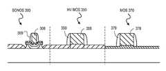
- FIG. 3Aillustrates a cross-sectional view representing operations in the formation of a semiconductor structure in which a SONOS channel implant is performed while a screening oxide is over the MOS and HV MOS regions of a substrate, in accordance with an embodiment of the present invention
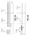
- FIG. 3Billustrates a cross-sectional view representing operations in the formation of a semiconductor structure in which a SONOS charge trapping dielectric stack is formed and the MOS and HV MOS regions are cleaned in preparation for forming a first gate insulator layer, in accordance with an embodiment of the present invention
- FIG. 3Cillustrates a cross-sectional view representing operations in the formation of a semiconductor structure in which a first gate insulator layer is formed over the MOS and HV MOS regions, in accordance with an embodiment of the present invention
- FIG. 3Dillustrates a cross-sectional view representing operations wherein SONOS and HV MOS device regions are masked while the first gate insulator layer in the MOS region is opened in a third region of the substrate to form a second gate insulator layer, in accordance with an embodiment of the present invention
- FIG. 3Eillustrates a cross-sectional view representing operations in the formation of a semiconductor structure in which a second gate insulator layer is formed in the MOS region, in accordance with an embodiment of the present invention
- FIG. 3Fillustrates a cross-sectional view representing operations in the formation of a semiconductor structure in which the SONOS oxide blocking layer, the HV MOS gate insulator layer and the MOS gate insulator layer are nitrided, in accordance with an embodiment of the present invention
- FIG. 3Gillustrates a cross-sectional view representing operations in the formation of a semiconductor structure in which a gate layer is deposited, in accordance with an embodiment of the present invention
- FIG. 3Hillustrates a cross-sectional view representing operations in the formation of a semiconductor structure in which a gate electrode is formed in accordance with an embodiment of the present invention
- FIG. 3Iillustrates a cross-sectional view representing operations in the formation of a semiconductor structure in which a sidewall spacer is formed in accordance with an embodiment of the present invention.
- FIG. 3Jillustrates a cross-sectional view representing operations in the formation of a semiconductor structure in which charge trap dielectric and gate dielectric is removed adjacent to sidewall spacers to complete definition of gate stacks, in accordance with an embodiment of the present invention.
- FIG. 4Aillustrates a cross-sectional view representing operations in the formation of a semiconductor structure having a SONOS gate stack with adjacent sidewall spacers as wells as HV MOS and MOS device gate stacks with adjacent sidewall spacers on a single substrate, in accordance with an embodiment of the present invention
- FIG. 4Billustrates a cross-sectional view representing operations in the formation of a semiconductor structure in which a multi-layered liner is deposited over the SONOS and logic devices, in accordance with an embodiment of the present invention
- FIG. 4Cillustrates a cross-sectional view representing operations in the formation of a semiconductor structure in which the top layer of the multi-layered liner is etched to form a disposable spacer, in accordance with an embodiment of the present invention
- FIG. 4Dillustrates a cross-sectional view representing operations in the formation of a semiconductor structure in which a HV MOS device receives a source and drain implant while the SONOS and MOS devices are masked, in accordance with an embodiment of the present invention
- FIG. 4Eillustrates a cross-sectional view representing operations in the formation of a semiconductor structure in which the disposable spacer is removed from the SONOS and logic devices, in accordance with an embodiment of the present invention
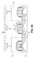
- FIG. 4Fillustrates a cross-sectional view representing operations in the formation of a semiconductor structure in which the bottom layer of the multi-layered liner is removed from the MOS device but retained over the SONOS and HV MOS devices, in accordance with an embodiment of the present invention
- FIG. 4Gillustrates a cross-sectional view representing operations in the formation of a semiconductor structure in which a silicide is formed on the MOS device but blocked by the bottom layer of the multi-layered liner over the SONOS and MOS devices, in accordance with an embodiment of the present invention
- FIG. 5illustrates a cross-sectional view representing operations in the formation of a semiconductor structure in which an interlayer dielectric (ILD) layer is formed on the sidewalls of the sidewall spacers adjacent to the MOS SONOS and HV MOS gate stacks, in accordance with an embodiment of the present invention
- ILDinterlayer dielectric
- FIG. 6Aillustrates a cross-sectional view representing operations in the formation of a semiconductor structure in which a stress inducing ILD layer is formed on the sidewall spacers adjacent to the MOS gate stack and formed on a bottom layer of the multi-layered liner over the SONOS and HV MOS gate stacks, in accordance with an embodiment of the present invention
- FIG. 6Billustrates a cross-sectional view representing operations in the formation of a semiconductor structure in which a low-stress ILD layer is formed on a bottom layer of the multi-layered liner covering the sidewall spacers adjacent to the SONOS and HV MOS gate stacks and formed on a stress inducing ILD layer over the MOS device, in accordance with an embodiment of the present invention.
- Embodiments of a non-volatile charge trap memory device integrated with logic devicesare described herein with reference to figures. However, particular embodiments may be practiced without one or more of these specific details, or in combination with other known methods, materials, and apparatuses. In the following description, numerous specific details are set forth, such as specific materials, dimensions and processes parameters etc. to provide a thorough understanding of the present invention. In other instances, well-known semiconductor design and fabrication techniques have not been described in particular detail to avoid unnecessarily obscuring the present invention.
- Reference throughout this specification to “an embodiment”means that a particular feature, structure, material, or characteristic described in connection with the embodiment is included in at least one embodiment of the invention. Thus, the appearances of the phrase “in an embodiment” in various places throughout this specification are not necessarily referring to the same embodiment of the invention. Furthermore, the particular features, structures, materials, or characteristics may be combined in any suitable manner in one or more embodiments.
- the terms “over,” “under,” “between,” and “on” as used hereinrefer to a relative position of one layer with respect to other layers.
- one layer deposited or disposed over or under another layermay be directly in contact with the other layer or may have one or more intervening layers.
- one layer deposited or disposed between layersmay be directly in contact with the layers or may have one or more intervening layers.
- a first layer “on” a second layeris in contact with that second layer.
- the relative position of one layer with respect to other layersis provided assuming operations deposit, modify and remove films relative to a starting substrate without consideration of the absolute orientation of the substrate.
- a nonvolatile charge trap dielectric stacksuch as a SONOS stack, is formed in a first region of a substrate after at least some of the well and channel implants of logic MOS devices are formed in a second region of the substrate.
- a nonvolatile charge trap dielectric stackis formed prior to any logic MOS gate oxidation processing.
- a SONOS stackis removed from the second region of the substrate, and a thermal oxidation forms a first gate insulator layer over the second region of the semiconductor substrate and thermally reoxidizes a blocking layer of the SONOS stack.
- a nitridation processnitridizes the first gate insulator layer and the blocking layer simultaneously.
- a nonvolatile charge trap memory device without silicide contactsis integrated with a logic device having silicide contacts. Such an embodiment may advantageously improve the reliability of the nonvolatile charge trap memory device by reducing silicide-related stress in the memory device.
- At least one of the logic deviceshas a longer lightly doped source and drain (i.e. offset source and drain) than at least another one of the logic devices to allow for HV operation (e.g. breakdown voltage greater than 10 V).
- the logic devicesinclude a HV PMOS device and a n-type MOS (NMOS) device
- the NMOS devicehas a smaller source and drain offset than does the HV PMOS device.
- the logic devicesinclude a HV PMOS device and a PMOS device
- the PMOS devicehas a smaller source and drain offset than does the HV PMOS.
- the lightly doped source and drain of the HV MOS deviceis a length greater than the thickness of a sidewall spacer adjacent to a sidewall of a gate stack of the MOS device.
- a multi-layered lineris employed to offset the HV MOS source and drain and also protect the nonvolatile charge trap memory device from silicidation.
- the multi-layered linerincludes at least a top and bottom layer
- a top layeris formed into a disposable spacer to offset the HV MOS source and drain and the bottom layer is used to mask the nonvolatile charge trap memory device during a silicidation of one or more of the logic devices.
- the bottom layeris additionally used to mask the HV MOS device during silicidation of one or more of the logic devices.
- the disposable spaceris removed selectively to the bottom layer of the multi-layered liner after the HV MOS source and drain are implanted.
- the bottom layer of the multi-layered lineris retained over the nonvolatile charge trap memory device as an ILD layer, covered with another ILD layer and then etched through during contact formation.
- the bottom layer of the multi-layered lineris retained over the nonvolatile charge trap memory device and the HV MOS device as an ILD layer.
- the stress in the bottom layer of the multi-layered lineris of opposite sign than that of a stress inducing ILD layer deposited over the bottom liner layer.
- the bottom layer of the multi-layered linerinduces compressive stress on the underlying device while the stress inducing ILD layer induces tensile stress on the underlying device.
- FIG. 1illustrates a flow diagram depicting sequences of particular modules employed in the fabrication process 100 of a non-volatile charge trap memory device integrated with a logic MOS device, in accordance with particular embodiments of the present invention.
- the methodsbegin with formation of isolation regions at module 101 .
- Isolation regionsmay be formed by any conventional technique, such as, but no limited to shallow trench isolation (STI) or local oxidation of silicon (LOCOS).
- STIshallow trench isolation
- LOCSlocal oxidation of silicon
- the process flowmay either proceed with well and/or channel implants at module 105 or delay the formation of the wells and/or channels until after formation of the non-volatile charge trapping dielectric stack and/or gate layer deposition.
- a non-volatile charge trapping dielectric stackis formed on a first region of a substrate at module 110 after at least some of the well and channel implants for the logic MOS transistors are formed at module 105 . It has been found that approximately 0.5 nm of silicon dioxide may be removed during a conventional post-implant resist strip process. The amount removed is greater if the silicon dioxide is a deposited oxide rather than a thermally grown oxide or if the silicon dioxide received an implant (e.g. 1.0 nm of silicon dioxide removed/strip process).
- the well and channel implant stripsmay also etch a non-volatile charge trapping dielectric stack (which may include silicon dioxide). While the nominal etch rate of the implant strip processes is quite small, it has also been found to form pin holes, or localized defects in the non-volatile charge trapping dielectric stack which may reduce the charge retention of a SONOS-type memory device. Thus, inserting the module forming the non-volatile charge trapping dielectric stack after the well and channel implant modules of a logic CMOS flow results in the least disruption to the non-volatile charge trapping dielectric stack.
- a gate insulator layeris formed on the second region of the substrate at module 120 .
- this sequence of forming the non-volatile charge trapping dielectric layer prior to forming the MOS gate insulator layeradvantageously utilizes the subsequent thermal treatments forming the MOS gate insulator layer to improve the quality of the non-volatile charge trapping dielectric stack, particularly a blocking layer.
- Logic MOS transistor degradation from thermal processing associated with formation of the non-volatile charge trapping dielectric layersis also avoided by forming the non-volatile charge trapping dielectric stack prior to forming the logic MOS gate insulator layer.
- a gate layeris deposited over both the MOS gate insulator layer and over the non-volatile charge trapping dielectric stack at module 130 .
- the well and/or channel implantsmay be performed at module 140 , after module 130 .
- the well and channel implantsmay advantageously dope the gate layer formed at module 130 in addition to forming the wells and/or channels.
- the gate layermay be then be patterned into gate electrodes at module 150 . Gate electrode patterning may occur simultaneously for both a non-volatile charge trap memory device in the first region of the substrate and a MOS device in the second region of the substrate.
- tip and/or HALO implantsmay be formed for all devices at module 155 and sidewall spacers formed for all devices at module 160 .
- Source and drain implantsmay then be formed for all devices at operation 165 .
- a multi-layered liner and disposable spacer processmay be performed at these operations to provide a high voltage CMOS transistor.
- a silicide processmay be performed to substantially complete the front end device fabrication.
- a multi-layered linermay be utilized to provide silicidation of logic CMOS without silicidation of the non-volatile charge trap memory device (i.e. selective silicidation).
- Backend metallizationas is conventional in the art, may then be performed to fabricate an integrated semiconductor structure comprising a non-volatile charge trap memory device and a MOS device on a single substrate.
- FIG. 2Aillustrates a flow diagram depicting fabrication process 200 including particular modules integrating formation of a charge-trapping dielectric stack with logic MOS gate insulator formation, in accordance with particular embodiments of the present invention.
- FIG. 2Adepicts particular process modules employed in certain implementations of the modules 105 , 110 , 120 and 130 of FIG. 1 .
- FIGS. 3A through 3Jfurther illustrate a cross-section of a SONOS memory device, a high voltage MOS device and a low voltage MOS device as the modules in the process flow of FIG. 2A are implemented.
- FIG. 2Billustrates a flow diagram depicting fabrication process 201 including particular modules integrating formation of a charge-trapping dielectric stack with a high voltage MOS transistor and with selective contact silicidation, in accordance with particular embodiments of the present invention.
- FIG. 2Bdepicts particular modules employed in certain implementations of the modules 155 , 160 , 165 and 170 of FIG. 1 .
- FIGS. 4A through 6Bfurther illustrate a cross-section of the non-volatile charge trap memory device, a high voltage MOS device and a low voltage MOS device as the modules in the process flow of FIG. 2B are implemented.
- process 200begins with STI formed in a substrate.
- the substratemay be a bulk substrate comprised of a single crystal of a material which may include, but is not limited to, silicon, germanium, silicon/germanium or a III-V compound semiconductor material.
- the substrateis comprised of a bulk layer with a top epitaxial layer.
- the bulk layeris comprised of a single crystal of a material which may include, but is not limited to, silicon, germanium, silicon/germanium, a III-V compound semiconductor material and quartz
- the top epitaxial layeris comprised of a single crystal layer which may include, but is not limited to, silicon, germanium, silicon/germanium and a III-V compound semiconductor material.
- the substrateis comprised of a top epitaxial layer on a middle insulator layer which is above a lower bulk layer.
- the top epitaxial layeris comprised of a single crystal layer which may include, but is not limited to, silicon (i.e. to form a silicon-on-insulator (SOI) semiconductor substrate), germanium, silicon/germanium and a III-V compound semiconductor material.
- the insulator layeris comprised of a material which may include, but is not limited to, silicon dioxide, silicon nitride and silicon oxy-nitride.
- the lower bulk layeris comprised of a single crystal which may include, but is not limited to, silicon, germanium, silicon/germanium, a III-V compound semiconductor material and quartz.
- a first well implantsuch an n-well implant is performed.
- Module 205will typically include forming a patterned photomask on a screening sacrificial dielectric layer, such as a silicon dioxide layer.
- the n-well implantis then performed in a region of the substrate, such as the region for MOS transistor 370 .
- the n-well implantincludes implanting a phosphorus species at concentrations and energies conventional for MOS devices.
- a single n-well implantmay be performed for PMOS transistors, PMOS HV transistors and p-type SONOS devices.
- a dry and/or wet stripis performed to remove the well implant photomask.
- Conventional plasma stripssuch as oxygen, forming gas, and the like may be employed.
- conventional wet stripssuch as piranha clean and ozone clean may be used. Because the charge trapping dielectric stack of the non-volatile memory device has not yet been formed, the silicon dioxide etch rate of the strip module 206 is of little concern.
- a module 207a p-well implant is performed.
- conventional implant speciessuch as boron, may be employed at typical doses and energies.
- the p-well implantmay be, but is not necessarily, a patterned implant such as the n-well implant of module 205 . If patterned, any of those strip processes of module 206 may be repeated.
- the p-well implantis performed in another area of the substrate, adjacent to an n-well region in preparation for an NMOS transistor.
- the p-well implantis an unmasked implant.
- any number of channel implantsmay also be performed at module 207 to adjust threshold voltages for specific device applications.
- an n-channel implantmay be performed in a region of the substrate where a NMOS transistor channel will be located, thereby setting a threshold voltage.
- the n-channel implantmay be of any conventional species (e.g. BF 2 ), dose and energy for a particular device type.
- a channel implant for a non-volatile charge trap memory devicemay also be performed in a first region of the substrate 302 , such as the region for SONOS device 300 of FIG. 3A .
- a channel implant for a high voltage MOS transistormay be performed in the substrate region of HV MOS transistor 350 .
- a p-channel implantmay likewise be performed, for example in the substrate region of MOS transistor 370 .
- a window 305 defined by photoresist 307is formed in the sacrificial dielectric layer 303 .
- the window 305may be of sub-micron dimension, for example, approximately 0.2 um in length and width.
- an oxygen plasma cleanis performed to descum photoresist residue from the corners of window 305 .
- a sacrificial silicon oxide layerwhich in one exemplary implementation is between 10 and 30 nm thick, may then be removed with a buffered oxide etchant (BOE) containing a surfactant, again to ensure window 305 is opened completely.
- BOEbuffered oxide etchant
- the isotropic etch of the screening sacrificial dielectric layer 303can be expected to undercut the photoresist 307 by an amount D 1 .
- the undercut amount D 1is important when window 305 is proximate to a logic device, such as in the region for HV MOS transistor 350 because logic device implants performed through the screening sacrificial dielectric layer 303 may have a different implant profile within the undercut region. Therefore, certain embodiments downsize the dimensions of window 305 . For example a 0.2 um drawn size may be downsized to 0.18 um to compensate for an undercut of 0.01 um on a side. In further embodiments, because the undercut of window 305 may become very close to an adjacent logic device, critical layer lithography tools are employed to reduce misregistration tolerances.
- the channel implantmay be performed and the photoresist 307 may be stripped.
- an annealmay be performed to complete module 207 .
- a rapid thermal annealis performed after implanting both the n-well and p-well.
- the rapid thermal annealmay be any known in the art to be suitable for MOS transistor applications.
- a non-volatile charge trapping dielectric stackis formed at module 210 .
- a non-volatile charge trapping dielectric stacksuch as an ONO charge trapping dielectric stack is then formed and patterned to remain only in memory cell areas at module 210 .
- a ONO charge trapping dielectric stack 306is comprised of a tunneling layer 304 A, a charge trapping layer 304 B and a blocking layer 304 C.
- the tunneling layer 304 Amay be any material and have any thickness allowing charge carriers to tunnel into the charge-trapping layer under a high gate bias condition while maintaining a suitable barrier to leakage under conditions of low gate bias.
- tunneling layer 304 Ais a commonly known dielectric layer, such as silicon dioxide (SiO 2 ), a silicon oxynitride (SiO x N y (H z )), a silicon dioxide that is subsequently nitridized, or a stack dielectric made of silicon dioxide and silicon nitride (Si 3 N 4 ) or silicon oxynitride, having a physical thickness of between about 1.5 nm and 3.0 nm.
- silicon dioxideSiO 2
- SiO x N y (H z )silicon oxynitride
- Si 3 N 4silicon nitride
- tunneling layer 304 Ais comprised of a dielectric layer having a dielectric constant greater than that of silicon nitride which may include, but is not limited to, hafnium oxide, zirconium oxide, hafnium silicate, hafnium oxy-nitride, hafnium zirconium oxide and lanthanum oxide.
- the charge trapping layer 304 B of the SONOS device 300may further include any commonly known charge trapping material and have any thickness suitable to store charge and, modulate the threshold voltage of the devices.
- charge trapping layer 304 Bis silicon nitride, silicon-rich silicon nitride, or silicon oxynitride.
- the trapping layer 304 Bhas a non-uniform stoichiometry across the thickness of trapping layer.
- the charge trapping layer 304 Bmay further include at least two silicon oxynitride layers having differing compositions of silicon, oxygen and nitrogen.
- a bottom oxynitride within charge trapping layer 304 Bhas a first composition with a high silicon concentration, a high oxygen concentration and a low nitrogen concentration to provide an oxygen-rich oxynitride.
- oxygen-rich and “silicon-rich”are relative to a stoichiometric silicon nitride, or “nitride,” commonly employed in the art having a composition of (Si 3 N 4 ) and with a refractive index (RI) of approximately 2.0.
- nitridecommonly employed in the art having a composition of (Si 3 N 4 ) and with a refractive index (RI) of approximately 2.0.
- RIrefractive index
- films described herein as “silicon-rich”entail a shift from stoichiometric silicon nitride toward a higher wt % of silicon with less oxygen than an “oxygen-rich” film.
- a silicon-rich silicon oxynitride filmis therefore more like silicon and the RI is increased toward the 3.5 RI of pure silicon.
- the bottom silicon oxynitridemay have a physical thickness between 2.5 nm and 4.0 nm corresponding to an EOT of between 1.5 nm and 5.0 nm.
- the charge trapping layer 304 Bmay further include a top silicon oxynitride with a high silicon concentration, a high nitrogen concentration and a low oxygen concentration to produce a silicon-rich silicon oxynitride.
- This second silicon oxynitridemay have a physical thickness of 4.0 to 6.0 nm for a charge trapping layer 304 B with a net physical thickness of 9 to 11 nm.
- the oxygen-rich stoichiometry of the first silicon oxynitrideprovides a good quality interface with tunneling layer 304 A.
- the composition of the oxygen-rich oxynitrideresults in an RI in the range of 1.7 and 1.9 and preferably about 1.8.
- the composition of the silicon-rich oxynitrideresults in an RI in the range of 1.8 and 2.0 and preferably about 1.9.
- multiple silicon nitride or silicon oxynitride charge trapping layersare formed in a low pressure CVD process using a silicon source, such as silane (SiH 4 ), dichlorosilane (SiH 2 Cl 2 ), tetrachlorosilane (SiCl 4 ) or Bis-TertiaryButylAmino Silane (BTBAS), a nitrogen source, such as N 2 , NH 3 , N 2 O or nitrogen trioxide (NO 3 ), and an oxygen-containing gas, such as O 2 or N 2 O.
- a silicon sourcesuch as silane (SiH 4 ), dichlorosilane (SiH 2 Cl 2 ), tetrachlorosilane (SiCl 4 ) or Bis-TertiaryButylAmino Silane (BTBAS)
- a nitrogen sourcesuch as N 2 , NH 3 , N 2 O or nitrogen trioxide (NO 3
- an oxygen-containing gassuch as O
- a silicon oxynitride charge trapping layercan be deposited over a tunneling layer by placing the substrate in a deposition chamber and the flow rate of ammonia (NH 3 ) gas and nitrous oxide (N 2 O) as mixed with a silicon precursor, such as dichlorosilane (SiH 2 Cl 2 ), to provide the desired gas ratios to form first an oxygen-rich oxynitride film and then a silicon-rich oxynitride film.
- NH 3ammonia
- N 2 Onitrous oxide
- Si precursorsuch as dichlorosilane (SiH 2 Cl 2 )
- oxygen-rich and silicon-rich filmsare relative to a stoichiometric Si 3 N 4 film
- formation of these filmsmay also be characterized based on the 3:1 volumetric flow rate ratio, SiH 2 Cl 2 :NH 3 , commonly employed to produce a stoichiometric (Si 3 N 4 ) with a CVD method.
- the oxygen-rich oxynitride filmis therefore formed with a relatively higher volumetric flow rate of oxidizer (e.g. N 2 O) than used for the silicon-rich oxynitride film while the both the oxygen-rich and silicon-rich oxynitride films are formed with a relatively higher volumetric flow rate of silicon precursor (e.g. SiH 2 Cl 2 ).
- an oxygen-rich oxynitride filmis formed by introducing a process gas mixture including N 2 O, NH 3 and SiH 2 Cl 2 , while maintaining the chamber at a pressure approximately in the range of 5-500 mTorr, and maintaining substrate 400 at a temperature approximately in the range of 700-850° C., for a period approximately in the range of 2.5-20 minutes.
- the process gas mixtureincludes N 2 O and NH 3 at a high volumetric flow rate ratio of about 1:1 to about 3:1 N 2 O:NH 3 while the SiH 2 Cl 2 to NH 3 is also at a high volumetric flow rate ratio from about 3.5:1 to 8:1 SiH 2 Cl 2 :NH 3 .
- the N 2 O:NH 3 ratiois about 2:1. while the SiH 2 Cl 2 :NH 3 is at a ratio of about 6:1.
- the gasesare introduced at a flow rate approximately in the range of 5-200 standard cubic centimeters per minute (sccm).
- a silicon-rich oxynitride filmis then formed by introducing a process gas mixture including N 2 O, NH 3 and SiH 2 Cl 2 , while maintaining the chamber at a pressure approximately in the range of 5-500 mTorr, and maintaining substrate 400 at a temperature approximately in the range of 700-850° C., for a period approximately in the range of 2.5-20 minutes in a batch furnace.
- the process gas mixtureincludes N 2 O and NH 3 at a volumetric flow rate ratio from about 1:8 to about 1:4 (N 2 O:NH 3 ) with SiH 2 Cl 2 and NH 3 at a volumetric flow rate ratio from about 3.5:1 to 5:1 (SiH 2 Cl 2 :NH 3 ).
- the N 2 O and NH 3are provided at a volumetric flow rate ratio of about 1:5 (N 2 O:NH 3 ) while the SiH 2 Cl 2 and NH 3 are at a volumetric flow rate ratio of about 4:1 (SiH 2 Cl 2 :NH 3 ).
- the gasesare introduced at a flow rate approximately in the range of 5 to 200 sccm.
- the blocking layer 304 C of the SONOS device 300may be any commonly known material with any thickness suitable to maintain a barrier to charge leakage without significantly decreasing the capacitance of the gate stack.
- blocking layer 304 Ccomprises a dielectric layer having a higher dielectric constant than silicon nitride which may include, but is not limited to, hafnium oxide, zirconium oxide, hafnium silicate, hafnium oxy-nitride, hafnium zirconium oxide and lanthanum oxide.
- the blocking layer 304 Cis silicon dioxide layer, silicon oxynitride layer, or a silicon dioxide and silicon nitride stack, with a physical thickness between about 3.0 nm and about 5.0 nm.
- Blocking layer 304 Ccan be formed by any suitable means including, for example, thermal oxidation or deposition with CVD techniques.
- the blocking layeris a deposited film formed with a high-temperature CVD process.
- the deposition processinvolves providing a silicon source, such as SiH 4 , SiH 2 Cl 2 , or SiCl 4 and an oxygen-containing gas, such as O 2 or N 2 O in a deposition chamber at a pressure of from about 50 mT to about 1000 mT, for a period of from about 10 minutes to about 120 minutes while maintaining the substrate at a temperature of from about 650° C. to about 850° C.
- the blocking layeris deposited sequentially in the same processing tool employed to form the charge trapping layer(s) 304 B. More preferably, the blocking layer is formed in the same processing tool as is both the charge trapping layer(s) 304 B and the tunneling layer 304 A without removing the substrate between operations.
- ONO charge trapping dielectric layers 304 A, 304 B and 304 Care then patterned into the ONO charge trapping dielectric stack 306 in the SONOS device 300 , as depicted in FIG. 3B .
- Conventional lithography and etching techniquesmay be employed to remove the charge trapping dielectric layers from other regions of the substrate, such as the HV MOS region 350 and MOS region 370 .
- a combination of dry and wet etchis performed to achieve a good stack sidewall profile.
- an inorganic spin-on anti-reflective coating (ARC), the blocking layer 304 C, and the dielectric layers 304 A and 304 Bare dry etched, with the dry etch process stopping on the sacrificial dielectric layer 303 .
- an etchantsuch as BOE, is employed to clear sacrificial dielectric layer 303 .
- the isotropic wet etchmay undercut the masked region. In this instance, undercutting the ONO charge trapping dielectric stack 306 , as denoted by the dashed line in FIG.
- module 212includes a non-HF gate insulator pre-clean. Hydrofluoric acid (HF) cleans, while conventionally performed in logic CMOS processes to remove any native or chemical oxides from the substrate 302 prior to forming a gate insulator, are disadvantageous when non-volatile charge trapping dielectric layers have already been formed and remain substantially unprotected.
- HFHydrofluoric acid
- module 212includes cleaning operations which are substantially free of HF.
- the substrate 302may retain a native or chemical oxide after the cleaning operations employed in the module 212 . It should be appreciated, that this concern of HF-based cleans attacking thin and critical dielectric layers is not present for standard logic MOS processes and is also not to be found in flash memory processes that protect such layers (e.g. tunnel oxide layer of flash memory device), with a polysilicon floating gate layer prior to the HF-based MOS gate insulator pre-clean.
- the non-HF pre-clean of module 212may include cleaning regimes known in the art to remove organic residues, such as, but not limited to piranha cleans, ozone cleans, and plasma cleans comprising O 2 or forming gas.
- the non-HF pre-cleanmay also include a RCA Standard Clean 1 (SC1) clean comprising a mixture of water, hydrogen peroxide and ammonium hydroxide (H 2 O:H 2 O 2 :NH 4 OH).
- SC1RCA Standard Clean 1
- a blocking layer 304 C formed by CVDmay be particularly susceptible to dielectric etchants because, for example, a deposited oxide blocking layer is typically of poorer quality than a thermally formed oxide layer. The poorer quality, be it from film stress, porosity, stoichiometry or otherwise, is associated with elevated etch rates relative to thermally grown dielectric layers. Therefore, the processes employed in the pre-clean module 212 should not be too aggressive.
- SC1 mixtures in logic CMOSare typically employed at a ratio of 5:1:1 H 2 O:H 2 O 2 :NH 4 OH, however it has been found that this chemistry may etch a CVD silicon dioxide blocking layer 304 C at an average rate of approximately 0.2 to 0.3 nm/minute. Perhaps more of a concern than this nominal etch rate, is the capacity for the SC1 chemistry to roughen the blocking layer 304 C. This roughness may be characterized with RMS roughness measurements. Also a concern associated with the SC1 chemistry is formation of pinhole defects in the top oxide which may be found at a low enough density to remain undetectable with RMS roughness measurements but nonetheless decrease the quality of the blocking layer 304 C.
- An ultra-dilute SC1is substantially more dilute than 5:1:1.
- the ultra-dilute SC1comprises approximately 0.001% NH4OH, and 0.1% H 2 O 2 in H 2 O.
- the non-HF pre-clean depicted in module 212may further include an RCA Standard Clean 2 (SC2) clean comprising a mixture of H 2 O:H 2 O 2 :HCl in a ratios known in the art.
- SC2RCA Standard Clean 2
- the non-HF pre-clean of module 212may include an ozonated water cleaning regime.
- the SC1 cleanmay be replaced by the ozonated water to remove the organics and etch residues. With elimination of the SC1 clean, few metals will be left on the substrate surface and the SC2 is therefore unnecessary.
- a logic MOS gate insulator layermay be formed on the substrate 302 .
- the logic MOS gate insulator layermay comprise any of the dielectric materials described elsewhere herein for any of the charge trapping dielectric layers 304 A, 304 B and 304 C, but in a particular embodiment, includes a thermally grown oxide as the gate insulator layer 314 of FIG. 3C .
- the gate insulator layer 314thermally grown, comprises silicon oxygen bonds.
- Reoxidation of the blocking layer 304 Cmay have the effect of densifying a CVD formed blocking oxide layer and improving the quality of the blocking oxide and thereby improving non-volatile charge trap memory device performance (e.g. reduced back injection).
- the reoxidation of the blocking layer 304 Cis depicted by the addition of field lines in FIG. 3C .
- formation of the gate insulator layer 314may further oxidize or reoxidize a portion or all of the charge trapping layer, such as a portion or all of the charge trapping layer 304 B shown in FIG. 3C , to achieve a graded band gap in the charge trapping layer 304 B.
- a graded band gapmay further improved non-volatile charge trap memory device performance. Reoxidation for this purpose after the deposition of the blocking layer 304 C may enable a more controlled diffusion of oxidizer to controllably oxidize or reoxidize the thin charge trapping layer 304 B.
- the formation of the gate insulator layer 314may include any conventional gate oxidation process whereby the substrate 302 is heated in the presence of an oxidizing gas such as, oxygen (O 2 ), nitrous oxide (N 2 O), nitric oxide (NO), ozone (O 3 ), and steam (H 2 O).
- an oxidizing gassuch as, oxygen (O 2 ), nitrous oxide (N 2 O), nitric oxide (NO), ozone (O 3 ), and steam (H 2 O).
- the gate oxidation processis performed at a higher temperature than the temperature at which the blocking layer 304 C is deposited.
- a dilute wet oxidationis employed to form the gate insulator layer 314 .
- the dilute wet oxidationis distinct from a conventional wet oxidation in that the H 2 :O 2 ratio is between 1 and 1.3.
- a dilute oxidation with an H 2 :O 2 ratio of approximately 1.2is performed at a temperature of between 800° C. and 900° C.
- the duration of the dilute oxidationis sufficient to grow between 5.0 nm and 15.0 nm of silicon dioxide where substrate 302 is silicon. In one such embodiment, the duration is sufficient to for an approximately 10 nm to 1.1 nm silicon dioxide layer to be formed on a silicon substrate.
- Such a dilute wet oxidation processadvantageously reoxidizes a deposited blocking layer 304 C and may further oxidize or reoxidize a portion of the charge trapping layer 304 B.
- a thermal oxidationforms a gate insulator layer 314 comprising silicon dioxide by consuming some of the silicon below the native or chemical oxide in the substrate 302 . Therefore, where multiple MOS gate insulator layer thicknesses are to be employed, for example one thickness in the region for HV MOS transistor 350 and a second thickness in the region of MOS transistor 370 , it may be advantageous to form the thickest gate insulator layer at module 214 of FIG.
- a photoresist layer 318 of FIG. 3Dis deposited and patterned to have an opening 319 formed over a region of the substrate 302 that is to have the next insulator material and/or insulator layer thickness.
- any previously formed gate insulator layerssuch as gate insulator layer 314 , depicted in FIG. 3D , are selectively removed to expose the substrate 302 .
- Conventional lithography and etch techniquesmay be employed at modules 218 and 222 , such as those described in reference to module 205 .
- a pre-cleanmay be performed on the substrate 302 .
- the photoresist layer 318protects the ONO charge trapping dielectric stack 306 a clean which would be detrimental to the ONO charge trapping dielectric stack 306 if it were not protected by the photoresist layer 318 may be performed at this time. While in certain embodiments the clean in module 224 is not performed, in either case, the photoresist layer 318 is stripped at module 226 , for example with conventional piranha clean and/or plasma ash operations, subsequent to the selective removal of the gate insulator layer(s).
- the non-HF pre-clean module 212may then be repeated in preparation of forming another gate insulator layer. Any of the processes described elsewhere herein for module 212 , such as an ultra-dilute SC1 clean, may be performed at this time to clean the substrate 302 in preparation for formation of an additional gate insulator layer in the opening 319 .
- another gate insulator layermay be formed at module 214 , such as gate insulator layer 320 .
- Gate insulator layer 320may be any of the materials described in reference to gate insulator layer 314 and not necessarily the same material as gate insulator layer 314 .
- gate insulator layer 320is a thermally grown layer comprising silicon dioxide.
- the gate insulator layer 320is formed over a third region of the substrate 302 , such for MOS transistor 370 , and is thinner than the gate insulator layer 314 formed over a second region of the substrate 302 , such as for HV MOS transistor 350 .
- the gate insulator layer 320 comprising silicon dioxideis formed to a thickness between approximately 3.0 nm and 8.0 nm while the gate insulator layer 314 is between 5 and 15 nm. Any of the processes described elsewhere herein for module 214 in reference to the formation of gate insulator layer 314 may also be employed to form the gate insulator layer 320 .
- the blocking layer 304 C and charge trapping layer 304 Bmay be reoxidized during the formation of the gate insulator layer 320 , much as described in reference to the formation of the gate insulator layer 314 . It should be appreciated such as reoxidation may be to a lesser extent than what occurs during the formation of the gate insulator layer 314 , particularly where the gate insulator layer 320 is formed thinner than the gate insulator layer 314 or where the gate insulator layer 320 is formed with a process other than the dilute steam oxidation described for one embodiment of the gate insulator layer 314 .
- modules 218 , 222 , 224 , 226 , 212 and 214may be repeated any number of times to provide more than the two gate insulator layer thicknesses described in the embodiment depicted in FIGS. 3C-3E .
- successively thinner gate insulator layersmay be formed with each iteration.
- a third gate insulator layermay be formed to between 2.0 nm and 3.5 nm, thinner than the gate insulator layer 314 and thinner than the gate insulator layer 320 .
- the embodiment depicted in FIG. 2Aproceeds to module 228 .
- the gate insulator layer 314 and the ONO charge trapping dielectric stack 306are nitrided or nitridized. Beyond nitriding the MOS gate insulator, this nitridation process serves to incorporate nitrogen into the ONO charge trapping dielectric stack 306 and improve the quality of the interfaces in the stack (e.g. between the dielectric layers 304 C and 304 B). This nitriding process, in certain embodiments, may incorporate approximately 4-10 wt % nitrogen into the blocking layer 304 C. In a particular embodiment, the nitridation process includes heating substrate 302 in an atmosphere including nitrogen at a temperature approximately in the range of 900-1100° C.
- nitridation of the ONO charge trapping dielectric stack 306is performed as part of forming the gate insulator layer (e.g. gate insulator layer 314 or gate insulator layer 320 ).
- the gate insulator layere.g. gate insulator layer 314 or gate insulator layer 320 .
- modules 214 and 228 of FIG. 2Aneed not be performed in separate process equipment, but rather merely a separate step of a single process recipe.
- This nitriding processmay incorporate approximately 4-10 wt % nitrogen into the blocking layer 304 C and approximately 4-10 wt % nitrogen into the gate insulator layer 314 and/or gate insulator layer 320 .
- a CVD furnaceis employed for the nitridation of module 228 and the duration of the nitridation may be for between 5 minutes and 10 minutes.
- a single wafer toolmay be employed for the nitridation of module 228 , exposing the gate insulator layer(s) and ONO charge trapping dielectric stack 306 to a nitrogen-containing environment for a duration in the range of approximately 30 seconds to approximately 60 seconds.
- the atmosphere including nitrogenis composed of a gas such as, but not limited to nitrogen (N 2 ), nitrous oxide (N 2 O), nitrogen dioxide (NO 2 ), nitric oxide (NO) and ammonia (NH 3 ).
- the nitrogen environmentfurther includes deuterium through an introduction of gases in which hydrogen has been replaced by deuterium, including, for example, the substitution of ND 3 for NH 3 .
- the substitution of deuterium for hydrogenmay advantageously passivate Si dangling bonds at the substrate interface, thereby increasing non-volatile charge trap memory device parametrics, such as NBTI (Negative Bias Temperature Instability) lifetime.
- NBTINegative Bias Temperature Instability
- nitridation in module 228is performed only once after the last gate insulator layer is formed, for example, after gate insulator layer 314 and gate insulator layer 320 have been formed.
- the single nitridation processtherefore nitridizes the ONO charge trapping dielectric stack 306 , the gate insulator layer 314 and the gate insulator layer 320 , as depicted by the field lines of FIG. 3F .
- the single nitridationprovides the benefits described herein while minimizing the thermal budget of the integrated process 200 .
- the nitridation process of module 228is performed only once after the first gate insulator is formed, for example, after gate insulator layer 314 .
- the ONO charge trapping dielectric stack 306is nitrided along with the gate insulator layer 314 .
- Nitridation only after the first gate insulatormay allow for some of the logic MOS devices fabricated on substrate 302 , such as in the region for HV MOS transistor 350 , to have a nitrided gate insulator layer while others do not, such as in the region for MOS transistor 370 .
- Embodiments employing nitridation immediately after the first gate insulator is formedmay also improve the ability of the ONO charge trapping dielectric stack 306 to withstand exposure to a subsequent HF-based clean performed prior to forming a subsequent gate insulator layer, such as gate insulator layer 320 .
- a silicon dioxide gate insulator layer 314is formed to a thickness of approximately 5.0 nm to 15.0 nm (consuming silicon below a native oxide on the substrate 302 ), the nitridation of module 228 is performed, a dilute HF-based clean is performed with the nitrided ONO charge trapping dielectric stack 306 exposed and then a silicon dioxide gate insulator layer 320 of a thickness between 2.0 and 8.0 nm is formed without consuming any significant thickness of native or chemical oxide on the substrate 302 .
- each successive gate insulator formedincludes the nitridation process of module 228 such that the ONO charge trapping dielectric stack 306 is exposed to a plurality of nitrogen anneals.
- a gate layer 330is deposited on both the ONO charge trapping dielectric stack 306 and on the gate insulator layers 314 and 320 , as depicted in FIG. 3G .
- the gate layermay be formed with any process conventionally known in the art.
- the gate layermay be any conductor or semiconductor material employed for gate layers in the art.
- the gate layer 330contains a metal, such as, but not limited to, hafnium, zirconium, titanium, tantalum, aluminum, ruthenium, palladium, platinum, cobalt and nickel, their silicides, their nitrides and their carbides.
- the gate layer 330is poly-silicon (p-silicon).
- the poly-silicon gate layer 330may be dual-doped to have N+ conductivity over a first portion of the first and/or second gate insulator layer ( 314 , 320 ) to form a HV NMOS and/or NMOS transistor, respectively, while having P+ conductivity over a second portion of the first and/or second gate insulator layer ( 314 , 320 ) to form a HV PMOS and/or PMOS transistor, respectively.
- the poly-silicon gate layer 330may be doped to have either N+ or P+ conductivity in the SONOS device 300 .
- the dual-doped poly-siliconmay form a P+ poly-silicon gate on an N-type SONOS memory device. Because the P+ poly-silicon gate has a Fermi level approximately 1 eV higher that an N+ poly-silicon gate, the larger workfunction of a P+ poly-silicon gate on an N-type SONOS device channel may improve reliability by reducing the number of charge carriers entering the ONO charge trapping dielectric stack 306 relative to an N-type SONOS device having an N+ poly-silicon gate.
- a SONOS gate electrodeis patterned over the substrate region of SONOS device 300 , while a HV MOS gate electrode 358 and MOS gate electrode 378 are patterned over the HV MOS transistor 350 and MOS transistor 370 substrate regions, respectively.
- the patterning of SONOS gate electrodeis performed with a dry etch stopping on the ONO charge trapping dielectric stack to protect the substrate semiconductor of the SONOS device 300 .
- Conventional tip and/or HALO implant processmay then be performed at module 255 of FIG. 2A to form lightly doped drains (not pictured).
- a sidewall spacer 309is then formed adjacent to a sidewall of the SONOS gate electrode 308 and on the ONO charge trapping dielectric stack 306 .
- Sidewall spacer 309may be comprised of silicon dioxide, silicon oxynitride, or silicon nitride and may also be patterned selectively to the ONO charge trapping dielectric stack 306 .
- the ONO charge trapping dielectric stack 306may then be subsequently etched to be self-aligned with sidewall spacer 309 to complete the formation of a SONOS gate stack 301 as depicted in FIG. 3J . Similar processes may also form spacers 359 and 379 adjacent to HV MOS gate stack 351 and a MOS gate stack 371 , respectively.
- FIG. 4Aillustrates a cross-sectional side view of devices following the source/drain implant module 263 of FIG. 2B .
- Illustration of gate stacks 301 , 351 and 371is simplified relative to those of FIG. 3J merely for clarity.
- SONOS device 300now includes source and drain 410 in substrate 302 having a conductivity opposite to the channel region.
- source and drain 410are N-type doped while channel region of substrate 302 is P-type doped.
- substrate 302is comprised of boron-doped single-crystal silicon having a boron concentration in the range of 1 ⁇ 10 15 -1 ⁇ 10 19 atoms/cm 3 .
- source and drain 410are comprised of phosphorous- or arsenic-doped regions having a concentration of N-type dopants in the range of 5 ⁇ 10 16 -1 ⁇ 10 20 atoms/cm 3 .
- source and drain 410have a depth in substrate 302 in the range of 80-200 nanometers.
- source and drain 410are P-type doped while the channel region of substrate 302 is N-type doped.
- lightly doped source and drain (LDD) 411formed at module 255 of FIG. 2A , extend under sidewall spacer 309 .
- Both the HV MOS transistor 350 and MOS transistor 370also include an LDD 461 and 481 , respectively.
- MOS transistor 370further includes a source and drain 480 adjacent to the sidewall spacer 379 and a distance T 1 away from below the sidewall of the gate stack 371 .
- the source and drain 480has an n-type conductivity and may, in certain embodiments, have substantially the same dopant concentration as that of the source and drain 410 .
- the HV MOS transistor 350lacks a source and drain analogous to the source and drain 410 and 480 .
- the HV MOS transistor 350may be masked with a photosensitive mask or with a commonly known non-photosensitive hardmask, such as, but not limited to, amorphous carbon, that was previously patterned.
- a multi-layered lineris then formed at module 264 of FIG. 2B .
- a liner 485is formed over the substrate 302 , covering the SONOS device 300 , the HV MOS transistor 350 and MOS transistor 370 .
- the liner 485is a multi-layered liner comprising a bottom liner layer 485 A and a top liner layer 485 B.
- the bottom liner layer 485 A and top liner layer 485 Bmay be any commonly employed materials.
- the top liner layer 485 Bmay be anisotropically etched selectively to the bottom liner layer 485 A.
- the bottom liner layer 485 Ais silicon dioxide while the top liner layer 485 B is a silicon nitride.
- the bottom liner layer 485 Ais a silicon nitride while the top liner layer 485 B is silicon dioxide.
- Other embodimentsmay include a top or bottom layer of silicon oxy-nitride, carbon-doped silicon nitride or boron-doped silicon nitride. While the multi-layered liner 485 has particular integration advantages discussed elsewhere herein, certain embodiments may also utilize a single layer liner comprised of, for example, a silicon dioxide layer or a silicon nitride layer.
- a thin bottom liner layer 485 Aadvantageously reduces the lateral thickness deposited on the sidewalls of the sidewall spacer 309 , 359 and 379 , which may be in close proximity to sidewalls of other devices.
- a thin bottom liner layer 485 Amay further reduce the amount of thickness variation in the film across different regions of the substrate 302 , the advantage of which is discussed elsewhere herein.
- a silicon nitride bottom liner layer 485 Ais formed to a thickness of between about 2 nm about 15 nm, preferably between about 5 nm and about 8 nm.
- the thickness of the top liner layer 485 Bmay be selected to provide the multi-layered liner with a desired thickness on the sidewall of the spacer 359 , as discussed further elsewhere herein.
- a silicon dioxide top liner layer 485 Bis formed to a thickness of between about 10 nm and 40 nm, preferably between about 20 nm and 30 nm.
- the layers of the multi-layered liner 485may be deposited with any commonly known techniques, such as, but not limited to, thermal oxidation, low pressure CVD (LPCVD) plasma enhanced CVD (PECVD) and ALD processes known to those of skill in the art.
- LPCVDlow pressure CVD
- PECVDplasma enhanced CVD
- a nitride bottom liner layer 485 Amay be deposited with a nitrogen precursor, such as NH 3
- a silicon precursorsuch as silane (SiH 4 ), dichlorosilane (SiH 2 Cl 2 ), or bis(tertiary-butylamino)silane (BTBAS).
- the depositionmay be performed at a substrate temperature, for example between approximately 550° C. and approximately 850° C., and at a deposition chamber pressure between approximately 100 millitorr (mT) and approximately 700 mT, to form a film having a thickness anywhere within the ranges previously described.
- An oxide layer top liner layer 485 Bmay be similarly formed by thermal or chemical oxidation of the bottom liner layer 485 A or a deposition process, such as an LPCVD employing any commonly known precursors, to form a film having a thickness anywhere within the ranges previously described.
- a deposition processsuch as an LPCVD employing any commonly known precursors
- either or both of the bottom liner layer 485 A and top liner layer 485 Bmay be deposited with techniques known to result in highly stressed films. Such stressed-film embodiments may make subsequent removal of either liner layer significantly faster and/or more selective to each other or underlying layers.
- the top liner layer 485 Bis anisotropically etched to form disposable sidewall spacer 486 along sidewalls of topography present under the multi-layered liner 485 .
- the top liner layer 485 Bis etched selectively to the bottom liner layer 485 A (i.e. the bottom liner layer 485 A provides an etch stop).
- the bottom liner layer 485 Aremains a substantially continuous film over the substrate 302 after the top liner layer 485 B is formed in to discrete disposable sidewall spacer 486 .
- the process selected to anisotropically etch the top liner layer 485 B to form disposable sidewall spacer 486is dependent on the materials chosen.
- a commonly known plasma etch processmay be used, such as one with a fluorine chemistry like carbon tetrafluoride (CF 4 ), having a high enough selectivity to silicon nitride to stop prior to etching through the bottom liner layer 485 A.
- CF 4carbon tetrafluoride
- any commonly known plasma etch processmay be used, such as one utilizing a fluorine-based chemistry, like nitrogen trifluoride (NF 3 ), or one utilizing a chlorine-based chemistry.
- NF 3nitrogen trifluoride
- a source and drainmay be formed for the HV MOS transistor at module 267 .
- the source and drain 460is formed with a p-type implant after a mask 498 is formed over the SONOS device 300 and MOS transistor 370 .
- Mask 498may be any commonly known photosensitive mask material (i.e. photoresist) or non-photosensitive mask, such as amorphous carbon, that was previously patterned.
- the p-type dopantmay be any commonly employed in the art, such as a Boron species.
- Other embodimentsinclude n-type dopants for HV NMOS transistors.
- the implantationis self-aligned to the gate stack 351 and offset from a sidewall of the gate stack 351 by a distance T 2 .
- the distance T 2is approximately equal to the sidewall thickness of the sidewall spacer 359 added to the sidewall thickness of the bottom liner layer 485 A added to the sidewall thickness of the disposable sidewall spacer 486 .
- the distance T 2 for the HV MOS transistor 350is greater than the distance T 1 for the MOS transistor 370 .
- the source and drain 460is offset by the distance T 2 , greater than T 1 , to increase the length of the LDD 461 .
- the thickness of the top liner layer 485 B deposited in the operation depicted in FIG. 4Bmay be predetermined to provide a disposable sidewall spacer 486 with the appropriate lateral width (thickness).
- the relatively greater offset represented by T 2may increase the breakdown voltage by reducing the encroachment of p-type dopant diffusion from the source and drain 460 into the channel region of the HV MOS transistor 350 during subsequent thermal processing.
- the p-type implantis made through the bottom liner layer 485 A.
- particular embodimentsemploy an advantageously thin bottom liner layer 485 A to improve the uniformity of the implant profile across the substrate 302 .
- the mask 498may be removed to expose the bottom liner layer 485 A covering the SONOS device 300 and MOS transistor 370 .
- the disposable sidewall spacer 486may then be removed. Removal of the disposable sidewall spacer 486 may advantageously increase the space between adjacent logic and nonvolatile charge trap memory devices to enable a higher packing density of devices (i.e. smaller device pitch). This is particularly advantageous for SONOS device 300 which may be part of a closely spaced array of SONOS devices, such as in a memory cell array. Removal of the disposable sidewall spacer 486 may also improve the step coverage of subsequently deposited ILD layers over high density SONOS and logic devices.
- Removal of the disposable sidewall spacer 486may be with a masked process, whereby the disposable sidewall spacer 486 is removed, for example, from the SONOS device 300 , but retained on the HV MOS transistor 350 .
- the disposable sidewall spacer 486is removed from the entire substrate 302 with an unmasked etch process.
- the etch processis selective to the bottom liner layer 485 A (i.e. the bottom liner layer 485 A acts as an etch stop for the etch process employed to remove the disposable sidewall spacer 486 .
- bottom liner layer 485 Asubstrate semiconductor and substrate insulator layers, such as shallow trench isolation (STI) are protected from the process employed to remove the disposable sidewall spacer 486 . Because it has been found that processing of the corner (not pictured, but is out of the plane of FIG. 4E ) formed where the STI meets the width of the gate stack 301 can greatly effect the performance of the SONOS device 300 , it is advantageous not to expose this region to the process employed for disposable spacer removal.
- STIshallow trench isolation
- the substrate 302 , the SONOS gate electrode 308 , the HV PMOS gate layer 358 and the NMOS gate layer 378 , as well as the sidewall spacers 309 , 359 and 379remain protected during the removal of the disposable sidewall spacer 486 .
- the material composition of the disposable sidewall spacer 486i.e. top liner layer 485 B is independent of the materials in the gate electrodes 308 , 358 and 378 and the sidewall spacers 309 , 359 and 379 .
- Disposable sidewall spacer 486may be removed with commonly known wet chemical or dry etch processes, depending on the materials employed in the particular implementation.
- the disposable sidewall spacer 486comprises silicon dioxide (i.e. a silicon dioxide top liner layer 485 B)
- a hydrofluoric acid (HF) based wet chemical etchmay be performed to remove the disposable sidewall spacer 486 selectively to a silicon nitride bottom liner layer 485 A.
- HFhydrofluoric acid
- an isotropic dry etch processsuch as one commonly known to have a high selectivity over the silicon nitride bottom liner layer 485 A may be employed.
- the disposable sidewall spacer 486comprises silicon nitride (i.e.
- a silicon nitride top liner layer 485 Ba hot phosphoric acid (H 3 PO 4 ) based wet chemical etch may be performed to remove the disposable sidewall spacer 486 selectively to a silicon dioxide bottom liner layer 485 A.
- a hot phosphoric acid (H 3 PO 4 ) based wet chemical etchmay be performed to remove the disposable sidewall spacer 486 selectively to a silicon dioxide bottom liner layer 485 A.
- an isotropic dry etch processsuch as one commonly known to have a high selectivity over the silicon dioxide bottom liner layer 485 A may be employed.
- the bottom liner layer 485 Amay be removed at module 269 to expose the source and drain regions of either or both of the SONOS and logic devices in preparation for a silicidation or salicidation (self-aligned silicidation) process at module 270 .
- a blanket strip of the bottom liner layer 485 Amay be performed to expose the source and drain regions of all devices.
- the strip processis preferably selective to the STI corner, the gate electrodes 308 , 358 and 378 and the sidewall spacers 309 , 359 and 379 .
- FIG. 4Fdepicts an alternate embodiment utilizing a patterned etch of the bottom liner layer 485 A.
- the patterned etchexposes only the source and drains of those devices for which silicide is desired.
- the bottom liner layer 485 Amay thereby further provide for device-dependent silicidation.
- a device-dependent silicidation processmay be advantageous for integrating a logic device, such as MOS transistor 370 , having silicide contacts with a non-volatile charge trap memory device, such as SONOS device 300 , having silicide-free contacts.
- a HV MOS devicesuch as HV MOS transistor 350 , may include either silicide or silicide-free contacts.
- the LDD region 461extends beyond the sidewall spacer 359 and bottom liner 485 A (i.e. below where the disposable sidewall spacer 486 was removed) and formation of silicide over this exposed LDD region may not be desirable.
- a mask 499is formed over the SONOS device 300 and HV MOS transistor 350 .
- Mask 499may be any commonly known photosensitive mask material (i.e. photoresist) or non-photosensitive mask, such as amorphous carbon, which is first patterned.
- the bottom liner layer 485 Amay then be etched to expose the regions of the MOS transistor 370 for subsequent silicidation. Removal of the bottom liner layer 485 A may be done by any commonly known means dependent on the material composition.
- the removal processshould be selective to the semiconductor substrate 302 and the STI (not shown). It may further be advantageously selective to the gate layer 378 , and the sidewall spacer 379 .
- a phosphoric acid-based wet chemical etchis utilized.
- an HF-based wet chemical etchmay be used. Because the thickness of bottom liner layer 485 A is relatively small, the etch and overetch time may be kept short to avoid eroding underlayers. Furthermore, a wet chemical etch rate may be greatly enhanced for those embodiments previously described having a highly stressed bottom liner layer 485 A.
- a dry plasma etchemploying commonly known process parameters may also be used to remove the unmasked portion of the bottom liner layer 485 A. Mask 499 may then be removed.
- a silicide processmay then be performed on those areas with exposed silicon.
- the silicide processmay be any commonly employed in the art, typically including a pre-clean etch, cobalt or nickel metal deposition, anneal and wet strip.
- silicide region 482may be formed on the exposed gate layer 378 and exposed source and drain region while blocked by the bottom liner layer 485 A from the SONOS device 300 and HV device (e.g. MOS transistor 350 ) regions.
- processingproceeds, as shown in FIG. 5 , with a removal of the bottom liner layer 485 A and deposition of ILD 504 .
- Such an embodimenthas the advantage of simplifying a subsequent contact etch because etching of ILD 504 will expose the source and drain 410 , the source and drain 460 and the silicide region 482 of the MOS transistor 370 .
- the devices with silicidemay be masked with any commonly known photosensitive mask material (i.e. photoresist) or non-photosensitive mask, such as amorphous carbon, which is first patterned. Masking of the silicided devices (e.g.
- MOS transistor 370is advantageous if the process employed to remove the bottom liner layer 485 A is nonselective to the silicide. Otherwise, a blanket strip of the bottom liner layer 485 A may be performed. A backend interconnect process may then begin with a deposition of ILD 504 over non-silicided SONOS device 300 , non-silicided HV MOS transistor 350 and silicided MOS transistor 370 .
- processingproceeds with deposition of an ILD over the bottom liner layer 485 A and over the silicide region 482 .
- the bottom liner layer 485 Ais incorporated as part of the backend ILD and subsequently removed during contact etch with an etch step selective over the silicide region 482 .
- the bottom liner layer 485 Amay be further utilized in a self-aligned contact (SAC) etch.
- SACself-aligned contact
- the SAC etchemploying an etch recipe highly selective to silicon nitride may reduce the contact dimension from that lithographically printed to the physical space between adjacent devices covered with the bottom liner layer 485 A.
- the ILD layer deposited over the bottom liner layer 485 A and silicide region 482may include a stress-inducing layer 504 A.
- Stress-inducing layer 504 Amay be composed of any material and have any thickness suitable to exert a stress on channel region of a logic device. Stress-inducing layer 504 A may advantageously increase the carrier mobility and drive currents of a logic device, such as MOS transistor 370 . In accordance with an embodiment of the present invention, stress-inducing layer 504 A is disposed directly on MOS transistor 370 .
- stress-inducing layer 504 Ais deposited to a thickness approximately in the range of 20-100 nanometers and is composed of a material such as, but not limited to, silicon nitride, silicon oxy-nitride, carbon-doped silicon nitride or boron-doped silicon nitride. In a specific embodiment, stress-inducing layer 504 A is a tensile stress-inducing layer.
- the bottom liner layer 485 Amay have been deposited under conditions to induce a stress opposing that of stress inducing layer 504 A.
- the bottom liner layer 485 Amay induce a compressive stress opposing a tensile stress in the stress inducing layer 504 A.
- the stress of the bottom liner layer 485 Areduces the cumulative stress on the SONOS device 300 to an amount less than half that induced by the stress inducing layer 504 A in absence of the bottom liner layer 485 A.
- the bottom liner layer 485 Amay therefore provide both selective silicidation and selective stress induction for integration of the SONOS device 300 and a logic device, such as MOS transistor 370 .
- ILD layer 504 Bmay then be deposited over stress inducing layer 504 A and planarized as part of a conventional backend interconnect process.
- the bottom liner layer 485 Amay provide an etch stop for removal of the stress-inducing layer 504 A from over the SONOS device 300 and HV MOS transistor 350 .
- the portion of stress-inducing layer 504 A above a nonvolatile charge trap memory device(e.g. SONOS device 300 ) may be removed through a lithography and etch process selective to the bottom liner layer 485 A.
- the portion of stress-inducing layer 504 A above MOS transistor 370is first masked with a patterned photo-resist layer and the portion of stress-inducing layer 504 A above SONOS device 300 is then removed by a technique such as, but not limited to, a wet etch process using hot phosphoric acid or a conventional dry etch process.
- the stress inducing layer 504 Amay be removed with high selectively to the bottom liner layer 485 A.
- the higher stress of the stress inducing layer 504 Amay provide selectivity to the bottom liner layer 485 A.
- the bottom liner layer 485 Atherefore may provide protection to the underlying structures during patterning of the stress inducing layer 504 A.
- removal of the stress inducing layer 504 Aalso removes the bottom liner layer 485 A.
- the ILD layer 504 Bmay then be deposited over both the bottom liner layer 485 A and over the stress inducing layer 504 A in preparation for further backend interconnect processing.
Landscapes
- Semiconductor Memories (AREA)
- Non-Volatile Memory (AREA)
Abstract
Description
Claims (16)
Priority Applications (2)
| Application Number | Priority Date | Filing Date | Title |
|---|---|---|---|
| US12/185,751US8679927B2 (en) | 2007-05-25 | 2008-08-04 | Integration of non-volatile charge trap memory devices and logic CMOS devices |
| US13/436,878US8871595B2 (en) | 2007-05-25 | 2012-03-31 | Integration of non-volatile charge trap memory devices and logic CMOS devices |
Applications Claiming Priority (4)
| Application Number | Priority Date | Filing Date | Title |
|---|---|---|---|
| US94014807P | 2007-05-25 | 2007-05-25 | |
| US94013707P | 2007-05-25 | 2007-05-25 | |
| US12/125,864US8093128B2 (en) | 2007-05-25 | 2008-05-22 | Integration of non-volatile charge trap memory devices and logic CMOS devices |
| US12/185,751US8679927B2 (en) | 2007-05-25 | 2008-08-04 | Integration of non-volatile charge trap memory devices and logic CMOS devices |
Related Parent Applications (1)
| Application Number | Title | Priority Date | Filing Date |
|---|---|---|---|
| US12/125,864ContinuationUS8093128B2 (en) | 2007-05-25 | 2008-05-22 | Integration of non-volatile charge trap memory devices and logic CMOS devices |
Related Child Applications (1)
| Application Number | Title | Priority Date | Filing Date |
|---|---|---|---|
| US13/436,878Continuation-In-PartUS8871595B2 (en) | 2007-05-25 | 2012-03-31 | Integration of non-volatile charge trap memory devices and logic CMOS devices |
Publications (2)
| Publication Number | Publication Date |
|---|---|
| US20080296664A1 US20080296664A1 (en) | 2008-12-04 |
| US8679927B2true US8679927B2 (en) | 2014-03-25 |
Family
ID=40072804
Family Applications (3)
| Application Number | Title | Priority Date | Filing Date |
|---|---|---|---|
| US12/125,864ActiveUS8093128B2 (en) | 2007-05-25 | 2008-05-22 | Integration of non-volatile charge trap memory devices and logic CMOS devices |
| US12/185,751Active2028-10-22US8679927B2 (en) | 2007-05-25 | 2008-08-04 | Integration of non-volatile charge trap memory devices and logic CMOS devices |
| US12/185,747Active2028-06-27US8143129B2 (en) | 2007-05-25 | 2008-08-04 | Integration of non-volatile charge trap memory devices and logic CMOS devices |
Family Applications Before (1)
| Application Number | Title | Priority Date | Filing Date |
|---|---|---|---|
| US12/125,864ActiveUS8093128B2 (en) | 2007-05-25 | 2008-05-22 | Integration of non-volatile charge trap memory devices and logic CMOS devices |
Family Applications After (1)
| Application Number | Title | Priority Date | Filing Date |
|---|---|---|---|
| US12/185,747Active2028-06-27US8143129B2 (en) | 2007-05-25 | 2008-08-04 | Integration of non-volatile charge trap memory devices and logic CMOS devices |
Country Status (3)
| Country | Link |
|---|---|
| US (3) | US8093128B2 (en) |
| CN (1) | CN101606236B (en) |
| WO (1) | WO2008147529A1 (en) |
Cited By (27)
| Publication number | Priority date | Publication date | Assignee | Title |
|---|---|---|---|---|
| US8871598B1 (en) | 2013-07-31 | 2014-10-28 | Freescale Semiconductor, Inc. | Non-volatile memory (NVM) and high-k and metal gate integration using gate-first methodology |
| US8877585B1 (en)* | 2013-08-16 | 2014-11-04 | Freescale Semiconductor, Inc. | Non-volatile memory (NVM) cell, high voltage transistor, and high-K and metal gate transistor integration |
| US8877568B2 (en) | 2010-10-29 | 2014-11-04 | Freescale Semiconductor, Inc. | Methods of making logic transistors and non-volatile memory cells |
| US8901632B1 (en) | 2013-09-30 | 2014-12-02 | Freescale Semiconductor, Inc. | Non-volatile memory (NVM) and high-K and metal gate integration using gate-last methodology |
| US8906764B2 (en) | 2012-01-04 | 2014-12-09 | Freescale Semiconductor, Inc. | Non-volatile memory (NVM) and logic integration |
| US8916432B1 (en)* | 2014-01-21 | 2014-12-23 | Cypress Semiconductor Corporation | Methods to integrate SONOS into CMOS flow |
| US8932925B1 (en) | 2013-08-22 | 2015-01-13 | Freescale Semiconductor, Inc. | Split-gate non-volatile memory (NVM) cell and device structure integration |
| US8951863B2 (en) | 2012-04-06 | 2015-02-10 | Freescale Semiconductor, Inc. | Non-volatile memory (NVM) and logic integration |
| US9006093B2 (en) | 2013-06-27 | 2015-04-14 | Freescale Semiconductor, Inc. | Non-volatile memory (NVM) and high voltage transistor integration |
| US9082650B2 (en) | 2013-08-21 | 2015-07-14 | Freescale Semiconductor, Inc. | Integrated split gate non-volatile memory cell and logic structure |
| US9082837B2 (en) | 2013-08-08 | 2015-07-14 | Freescale Semiconductor, Inc. | Nonvolatile memory bitcell with inlaid high k metal select gate |
| US9087913B2 (en) | 2012-04-09 | 2015-07-21 | Freescale Semiconductor, Inc. | Integration technique using thermal oxide select gate dielectric for select gate and apartial replacement gate for logic |
| US9112056B1 (en) | 2014-03-28 | 2015-08-18 | Freescale Semiconductor, Inc. | Method for forming a split-gate device |
| US9111865B2 (en) | 2012-10-26 | 2015-08-18 | Freescale Semiconductor, Inc. | Method of making a logic transistor and a non-volatile memory (NVM) cell |
| US9129855B2 (en) | 2013-09-30 | 2015-09-08 | Freescale Semiconductor, Inc. | Non-volatile memory (NVM) and high-k and metal gate integration using gate-first methodology |
| US9129996B2 (en) | 2013-07-31 | 2015-09-08 | Freescale Semiconductor, Inc. | Non-volatile memory (NVM) cell and high-K and metal gate transistor integration |
| US9136129B2 (en) | 2013-09-30 | 2015-09-15 | Freescale Semiconductor, Inc. | Non-volatile memory (NVM) and high-k and metal gate integration using gate-last methodology |
| US9231077B2 (en) | 2014-03-03 | 2016-01-05 | Freescale Semiconductor, Inc. | Method of making a logic transistor and non-volatile memory (NVM) cell |
| US9252246B2 (en) | 2013-08-21 | 2016-02-02 | Freescale Semiconductor, Inc. | Integrated split gate non-volatile memory cell and logic device |
| US9257445B2 (en) | 2014-05-30 | 2016-02-09 | Freescale Semiconductor, Inc. | Method of making a split gate non-volatile memory (NVM) cell and a logic transistor |
| US9275864B2 (en) | 2013-08-22 | 2016-03-01 | Freescale Semiconductor,Inc. | Method to form a polysilicon nanocrystal thin film storage bitcell within a high k metal gate platform technology using a gate last process to form transistor gates |
| US9343314B2 (en) | 2014-05-30 | 2016-05-17 | Freescale Semiconductor, Inc. | Split gate nanocrystal memory integration |
| US9379222B2 (en) | 2014-05-30 | 2016-06-28 | Freescale Semiconductor, Inc. | Method of making a split gate non-volatile memory (NVM) cell |
| US9472418B2 (en) | 2014-03-28 | 2016-10-18 | Freescale Semiconductor, Inc. | Method for forming a split-gate device |
| US10446401B2 (en)* | 2017-11-29 | 2019-10-15 | Renesas Electronics Corporation | Method of manufacturing semiconductor device |
| US10714486B2 (en) | 2018-09-13 | 2020-07-14 | Sandisk Technologies Llc | Static random access memory cell employing n-doped PFET gate electrodes and methods of manufacturing the same |
| US11049946B2 (en) | 2015-08-31 | 2021-06-29 | Semiconductor Energy Laboratory Co., Ltd. | Semiconductor device |
Families Citing this family (64)
| Publication number | Priority date | Publication date | Assignee | Title |
|---|---|---|---|---|
| US7642152B2 (en)* | 2005-09-07 | 2010-01-05 | United Microelectronics Corp. | Method of fabricating spacers and cleaning method of post-etching and semiconductor device |
| US7563702B2 (en)* | 2006-04-28 | 2009-07-21 | Hynix Semiconductor Inc. | Method for fabricating semiconductor device |
| US8643124B2 (en) | 2007-05-25 | 2014-02-04 | Cypress Semiconductor Corporation | Oxide-nitride-oxide stack having multiple oxynitride layers |
| US9449831B2 (en) | 2007-05-25 | 2016-09-20 | Cypress Semiconductor Corporation | Oxide-nitride-oxide stack having multiple oxynitride layers |
| US8940645B2 (en) | 2007-05-25 | 2015-01-27 | Cypress Semiconductor Corporation | Radical oxidation process for fabricating a nonvolatile charge trap memory device |
| US8614124B2 (en)* | 2007-05-25 | 2013-12-24 | Cypress Semiconductor Corporation | SONOS ONO stack scaling |
| US8633537B2 (en) | 2007-05-25 | 2014-01-21 | Cypress Semiconductor Corporation | Memory transistor with multiple charge storing layers and a high work function gate electrode |
| US9299568B2 (en) | 2007-05-25 | 2016-03-29 | Cypress Semiconductor Corporation | SONOS ONO stack scaling |
| US20090179253A1 (en) | 2007-05-25 | 2009-07-16 | Cypress Semiconductor Corporation | Oxide-nitride-oxide stack having multiple oxynitride layers |
| US8093128B2 (en)* | 2007-05-25 | 2012-01-10 | Cypress Semiconductor Corporation | Integration of non-volatile charge trap memory devices and logic CMOS devices |
| US8063434B1 (en) | 2007-05-25 | 2011-11-22 | Cypress Semiconductor Corporation | Memory transistor with multiple charge storing layers and a high work function gate electrode |
| US7633125B2 (en)* | 2007-08-31 | 2009-12-15 | Intel Corporation | Integration of silicon boron nitride in high voltage and small pitch semiconductors |
| US20090065841A1 (en)* | 2007-09-06 | 2009-03-12 | Assaf Shappir | SILICON OXY-NITRIDE (SiON) LINER, SUCH AS OPTIONALLY FOR NON-VOLATILE MEMORY CELLS |
| KR100884344B1 (en)* | 2007-10-10 | 2009-02-18 | 주식회사 하이닉스반도체 | Nonvolatile memory device having an asymmetric source / drain junction and method for manufacturing the same |
| US9431549B2 (en) | 2007-12-12 | 2016-08-30 | Cypress Semiconductor Corporation | Nonvolatile charge trap memory device having a high dielectric constant blocking region |
| US7947606B2 (en)* | 2008-05-29 | 2011-05-24 | Infineon Technologies Ag | Methods of forming conductive features and structures thereof |
| JP2010205908A (en)* | 2009-03-03 | 2010-09-16 | Toshiba Corp | Semiconductor device, and method of manufacturing the same |
| US8071453B1 (en) | 2009-04-24 | 2011-12-06 | Cypress Semiconductor Corporation | Method of ONO integration into MOS flow |
| US9102522B2 (en) | 2009-04-24 | 2015-08-11 | Cypress Semiconductor Corporation | Method of ONO integration into logic CMOS flow |
| US20110101442A1 (en) | 2009-11-02 | 2011-05-05 | Applied Materials, Inc. | Multi-Layer Charge Trap Silicon Nitride/Oxynitride Layer Engineering with Interface Region Control |
| US8288811B2 (en)* | 2010-03-22 | 2012-10-16 | Micron Technology, Inc. | Fortification of charge-storing material in high-K dielectric environments and resulting apparatuses |
| US8637916B2 (en)* | 2010-04-12 | 2014-01-28 | United Microelectronics Corp. | Semiconductor device with mini SONOS cell |
| US8409950B1 (en)* | 2010-11-08 | 2013-04-02 | Northrop Grumman Systems Corporation | Method for integrating SONOS non-volatile memory into a sub-90 nm standard CMOS foundry process flow |
| US9257292B2 (en) | 2011-03-30 | 2016-02-09 | Tokyo Electron Limited | Etch system and method for single substrate processing |
| CN102820301A (en)* | 2011-06-09 | 2012-12-12 | 华东师范大学 | TN (tunnel nitrate)-SONOS (silicon oxide nitrate oxide silicon) memory with composite nitrogen-based dielectric tunneling layer |
| TWI489528B (en)* | 2011-07-12 | 2015-06-21 | Winbond Electronics Corp | Method of fabricating memory |
| US8685813B2 (en) | 2012-02-15 | 2014-04-01 | Cypress Semiconductor Corporation | Method of integrating a charge-trapping gate stack into a CMOS flow |
| CN102543887A (en)* | 2012-02-28 | 2012-07-04 | 上海华力微电子有限公司 | Method for improving operating speed of SONOS (Silicon Oxide Nitride Oxide Silicon) device by changing channel stress |
| CN102569408A (en)* | 2012-02-28 | 2012-07-11 | 上海华力微电子有限公司 | SONOS (Silicon Oxide Nitride Oxide Silicon) unit transistor with high erasing speed and manufacturing method thereof |
| EP3229276A1 (en)* | 2012-03-31 | 2017-10-11 | Cypress Semiconductor Corporation | Integration of non-volatile charge trap memory devices and logic cmos devices |
| CN102709178B (en)* | 2012-05-22 | 2015-08-19 | 上海华力微电子有限公司 | A kind of method forming dual stressed layers silicon nitride film |
| KR102078611B1 (en)* | 2012-07-01 | 2020-04-08 | 롱지튜드 플래쉬 메모리 솔루션즈 리미티드 | Memory transistor with multiple charge storing layers |
| US8994006B2 (en) | 2012-10-02 | 2015-03-31 | International Business Machines Corporation | Non-volatile memory device employing semiconductor nanoparticles |
| US9026719B2 (en) | 2012-11-15 | 2015-05-05 | Elwha, Llc | Intelligent monitoring for computation in memory |
| US8796098B1 (en)* | 2013-02-26 | 2014-08-05 | Cypress Semiconductor Corporation | Embedded SONOS based memory cells |
| US9406565B2 (en)* | 2013-03-15 | 2016-08-02 | GlobalFoundries, Inc. | Methods for fabricating integrated circuits with semiconductor substrate protection |
| US8883624B1 (en) | 2013-09-27 | 2014-11-11 | Cypress Semiconductor Corporation | Integration of a memory transistor into high-K, metal gate CMOS process flow |
| CN104576522B (en)* | 2013-10-16 | 2017-10-24 | 上海华虹宏力半导体制造有限公司 | The integrated approach of surface channel CMOS logic device and SONOS devices |
| US10084016B2 (en) | 2013-11-21 | 2018-09-25 | Micron Technology, Inc. | Cross-point memory and methods for fabrication of same |
| US20150171104A1 (en) | 2013-12-12 | 2015-06-18 | Cypress Semiconductor Corporation | Complementary sonos integration into cmos flow |
| US9484196B2 (en) | 2014-02-25 | 2016-11-01 | Micron Technology, Inc. | Semiconductor structures including liners comprising alucone and related methods |
| US9577010B2 (en) | 2014-02-25 | 2017-02-21 | Micron Technology, Inc. | Cross-point memory and methods for fabrication of same |
| US9806129B2 (en) | 2014-02-25 | 2017-10-31 | Micron Technology, Inc. | Cross-point memory and methods for fabrication of same |
| US11223014B2 (en) | 2014-02-25 | 2022-01-11 | Micron Technology, Inc. | Semiconductor structures including liners comprising alucone and related methods |
| US10249819B2 (en) | 2014-04-03 | 2019-04-02 | Micron Technology, Inc. | Methods of forming semiconductor structures including multi-portion liners |
| US9768378B2 (en) | 2014-08-25 | 2017-09-19 | Micron Technology, Inc. | Cross-point memory and methods for fabrication of same |
| JP6407644B2 (en) | 2014-09-24 | 2018-10-17 | ルネサスエレクトロニクス株式会社 | Manufacturing method of semiconductor device |
| CN104332443A (en)* | 2014-10-30 | 2015-02-04 | 上海华虹宏力半导体制造有限公司 | Technical method of SONOS (Silicon Oxide Nitride Oxide Semiconductor) device |
| CN106298671A (en)* | 2015-05-11 | 2017-01-04 | 联华电子股份有限公司 | Method for manufacturing non-volatile memory with SONOS memory unit |
| US9767407B2 (en)* | 2015-09-18 | 2017-09-19 | Samsung Electronics Co., Ltd. | Weighting device, neural network, and operating method of the weighting device |
| US9537016B1 (en)* | 2016-02-03 | 2017-01-03 | Taiwan Semiconductor Manufacturing Company Ltd. | Memory device, gate stack and method for manufacturing the same |
| JP6880595B2 (en)* | 2016-08-10 | 2021-06-02 | セイコーエプソン株式会社 | Semiconductor devices and their manufacturing methods |
| JP2017028307A (en)* | 2016-10-05 | 2017-02-02 | ルネサスエレクトロニクス株式会社 | Semiconductor device manufacturing method |
| JP2017224864A (en)* | 2017-09-21 | 2017-12-21 | ルネサスエレクトロニクス株式会社 | Semiconductor device manufacturing method |
| JP2019079845A (en)* | 2017-10-20 | 2019-05-23 | ルネサスエレクトロニクス株式会社 | Method for manufacturing semiconductor device |
| US10699960B2 (en) | 2018-06-27 | 2020-06-30 | Taiwan Semiconductor Manufacturing Co., Ltd. | Methods for improving interlayer dielectric layer topography |
| US11527625B1 (en)* | 2019-07-02 | 2022-12-13 | Marvell Asia Pte Ltd | Electrical performance and reliability of a semiconductor device comprising continuous diffusion structures |
| US11615979B2 (en)* | 2019-12-18 | 2023-03-28 | Disco Corporation | Method of processing wafer |
| US11799006B2 (en)* | 2021-05-13 | 2023-10-24 | Taiwan Semiconductor Manufacturing Company, Ltd. | Mask-free process for improving drain to gate breakdown voltage in semiconductor devices |
| CN113257663A (en)* | 2021-07-15 | 2021-08-13 | 广州粤芯半导体技术有限公司 | Method for forming cobalt silicide film layer |
| CN114496798B (en)* | 2022-01-27 | 2024-12-20 | 上海华力集成电路制造有限公司 | Method for manufacturing semiconductor device |
| US12336264B2 (en)* | 2022-06-21 | 2025-06-17 | Nanya Technology Corporation | Semiconductor device having gate electrodes with dopant of different conductive types |
| TWI847564B (en)* | 2022-06-21 | 2024-07-01 | 南亞科技股份有限公司 | Semiconductor device having gate electrodes with dopant of different conductive types |
| WO2024025896A2 (en)* | 2022-07-25 | 2024-02-01 | Evommune, Inc. | Protein kinase c (pkc) theta inhibitor compounds |
Citations (58)
| Publication number | Priority date | Publication date | Assignee | Title |
|---|---|---|---|---|
| US4843023A (en) | 1985-09-25 | 1989-06-27 | Hewlett-Packard Company | Process for forming lightly-doped-drain (LDD) without extra masking steps |
| US5405791A (en) | 1994-10-04 | 1995-04-11 | Micron Semiconductor, Inc. | Process for fabricating ULSI CMOS circuits using a single polysilicon gate layer and disposable spacers |
| US5404791A (en) | 1991-10-31 | 1995-04-11 | Alliedsignal Europe Services Techniques | Pressure regulation device for a hydraulic system |
| US5573963A (en) | 1995-05-03 | 1996-11-12 | Vanguard International Semiconductor Corporation | Method of forming self-aligned twin tub CMOS devices |
| US5773343A (en) | 1995-05-12 | 1998-06-30 | Lg Semicon Co., Ltd. | Semiconductor device having a recessed channel structure and method for fabricating the same |
| US5793089A (en) | 1997-01-10 | 1998-08-11 | Advanced Micro Devices, Inc. | Graded MOS transistor junction formed by aligning a sequence of implants to a selectively removable polysilicon sidewall space and oxide thermally grown thereon |
| US5861347A (en)* | 1997-07-03 | 1999-01-19 | Motorola Inc. | Method for forming a high voltage gate dielectric for use in integrated circuit |
| US6025267A (en) | 1998-07-15 | 2000-02-15 | Chartered Semiconductor Manufacturing, Ltd. | Silicon nitride--TEOS oxide, salicide blocking layer for deep sub-micron devices |
| US6074915A (en)* | 1998-08-17 | 2000-06-13 | Taiwan Semiconductor Manufacturing Company | Method of making embedded flash memory with salicide and sac structure |
| US6153543A (en) | 1999-08-09 | 2000-11-28 | Lucent Technologies Inc. | High density plasma passivation layer and method of application |
| US6174774B1 (en) | 1997-03-12 | 2001-01-16 | Lg Semicon Co., Ltd. | Method of fabricating semiconductor device |
| US6277683B1 (en) | 2000-02-28 | 2001-08-21 | Chartered Semiconductor Manufacturing Ltd. | Method of forming a sidewall spacer and a salicide blocking shape, using only one silicon nitride layer |
| US6429081B1 (en) | 2001-05-17 | 2002-08-06 | Taiwan Semiconductor Manufacturing Company | Parasitic surface transfer transistor cell (PASTT cell) for bi-level and multi-level NAND flash memory |
| US6518113B1 (en) | 2001-02-06 | 2003-02-11 | Advanced Micro Devices, Inc. | Doping of thin amorphous silicon work function control layers of MOS gate electrodes |
| US6599795B2 (en) | 2000-08-07 | 2003-07-29 | Mitsubishi Denki Kabushiki Kaisha | Method of manufacturing semiconductor device including a step of forming a silicide layer, and semiconductor device manufactured thereby |
| US20030227049A1 (en) | 2002-06-11 | 2003-12-11 | Mitsubishi Denki Kabushiki Kaisha | Non-volatile semiconductor memory device |
| US20040067619A1 (en)* | 2002-10-04 | 2004-04-08 | Hiroaki Niimi | Method for non-thermally nitrided gate formation for high voltage devices |
| US20040071030A1 (en) | 2002-07-03 | 2004-04-15 | Kabushiki Kaisha Toshiba | Semiconductor integrated circuits, fabrication method for the same and semiconductor integrated circuit systems |
| US20040129986A1 (en)* | 2002-11-28 | 2004-07-08 | Renesas Technology Corp. | Nonvolatile semiconductor memory device and manufacturing method thereof |
| US6787419B2 (en) | 2003-01-14 | 2004-09-07 | Ememory Technology Inc. | Method of forming an embedded memory including forming three silicon or polysilicon layers |
| US20040207002A1 (en) | 2003-01-09 | 2004-10-21 | Samsung Electronics Co., Ltd. | SONOS memory device having side gate stacks and method of manufacturing the same |
| US6818558B1 (en) | 2001-07-31 | 2004-11-16 | Cypress Semiconductor Corporation | Method of manufacturing a dielectric layer for a silicon-oxide-nitride-oxide-silicon (SONOS) type devices |
| US20040227196A1 (en)* | 2003-04-08 | 2004-11-18 | Matsushita Electric Industrial Co., Ltd. | Method for fabricating semiconductor device and semiconductor device |
| US20050056892A1 (en) | 2003-09-15 | 2005-03-17 | Seliskar John J. | Fully-depleted castellated gate MOSFET device and method of manufacture thereof |
| US20050116279A1 (en) | 2003-10-06 | 2005-06-02 | Koh Kwan J. | Flash memory devices and methods of fabricating the same |
| US20050186741A1 (en) | 2004-02-20 | 2005-08-25 | Tower Semiconductor Ltd. | SONOS embedded memory with CVD dielectric |
| US6946349B1 (en) | 2004-08-09 | 2005-09-20 | Chartered Semiconductor Manufacturing Ltd. | Method for integrating a SONOS gate oxide transistor into a logic/analog integrated circuit having several gate oxide thicknesses |
| US20050224866A1 (en) | 2002-08-30 | 2005-10-13 | Fasl Llc | Semiconductor memory device and manufacturing method thereof |
| US20050266637A1 (en) | 2004-06-01 | 2005-12-01 | Macronix International Co., Ltd. | Tunnel oxynitride in flash memories |
| US20050275010A1 (en) | 2004-06-10 | 2005-12-15 | Hung-Wei Chen | Semiconductor nano-wire devices and methods of fabrication |
| US7015100B1 (en) | 2004-12-23 | 2006-03-21 | United Microelectronics Corp. | Method of fabricating one-time programmable read only memory |
| US20060081331A1 (en) | 2003-10-15 | 2006-04-20 | Campian Jonathon R | Apparatus and method for holding materials for the forming and joining thereof |
| US7045424B2 (en) | 2003-08-14 | 2006-05-16 | Samsung Electronics Co., Ltd. | Method of fabricating local SONOS type gate structure and method of fabricating nonvolatile memory cell having the same |
| US20060202263A1 (en)* | 2005-03-14 | 2006-09-14 | Chang-Hyun Lee | Nonvolatile semiconductor memory device and method of fabricating the same |
| US20060226490A1 (en) | 2005-04-06 | 2006-10-12 | Burnett James D | Interlayer dielectric under stress for an integrated circuit |
| US20060281331A1 (en) | 2004-11-29 | 2006-12-14 | Macronix International Co., Ltd. | Charge trapping dielectric structure for non-volatile memory |
| US7172940B1 (en) | 2005-09-15 | 2007-02-06 | Ememory Technology Inc. | Method of fabricating an embedded non-volatile memory device |
| US20070066087A1 (en) | 2005-09-20 | 2007-03-22 | Dongbuanam Semiconductors Inc. | Method of manufacturing a semiconductor device |
| US7250654B2 (en) | 2005-11-07 | 2007-07-31 | Ememory Technology Inc. | Non-volatile memory device |
| US7262457B2 (en) | 2004-01-05 | 2007-08-28 | Ememory Technology Inc. | Non-volatile memory cell |
| US20070215940A1 (en) | 2006-03-16 | 2007-09-20 | Spansion Llc | Vertical semiconductor device |
| US20070272971A1 (en) | 2003-05-28 | 2007-11-29 | Chang-Hyun Lee | Non-Volatile Memory Device and Method of Fabricating the Same |
| US20080048237A1 (en) | 2006-07-26 | 2008-02-28 | Kabushiki Kaisha Toshiba | Nonvolatile semiconductor memory device |
| US20080057644A1 (en)* | 2006-08-31 | 2008-03-06 | Dong-Hwa Kwak | Semiconductor devices having a convex active region and methods of forming the same |
| US20080087942A1 (en) | 2006-10-11 | 2008-04-17 | Macronix International Co., Ltd. | Vertical channel memory and manufacturing method thereof and operating method using the same |
| US20080290398A1 (en) | 2007-05-25 | 2008-11-27 | Igor Polishchuk | Nonvolatile charge trap memory device having <100> crystal plane channel orientation |
| US20080293255A1 (en) | 2007-05-25 | 2008-11-27 | Krishnaswamy Ramkumar | Radical oxidation process for fabricating a nonvolatile charge trap memory device |
| US20080293207A1 (en) | 2007-05-25 | 2008-11-27 | Koutny Jr William W C | Integration of non-volatile charge trap memory devices and logic cmos devices |
| US20090179253A1 (en) | 2007-05-25 | 2009-07-16 | Cypress Semiconductor Corporation | Oxide-nitride-oxide stack having multiple oxynitride layers |
| US20090206385A1 (en) | 2008-02-15 | 2009-08-20 | Samsung Electronics Co., Ltd. | Non-volatile memory device and method of operating the same |
| US7646041B2 (en) | 2006-12-04 | 2010-01-12 | Samsung Electronics Co., Ltd. | Non-volatile memory devices including vertical channels, methods of operating, and methods of fabricating the same |
| US7692246B2 (en) | 2006-01-12 | 2010-04-06 | Infineon Technologies Ag | Production method for a FinFET transistor arrangement, and corresponding FinFET transistor arrangement |
| US7723789B2 (en) | 2007-09-11 | 2010-05-25 | National Chiao Tung University | Nonvolatile memory device with nanowire channel and method for fabricating the same |
| US20100252877A1 (en) | 2009-04-06 | 2010-10-07 | Toshiro Nakanishi | Non-Volatile Semiconductor Memory Devices Having Charge Trap Layers Between Word Lines and Active Regions Thereof |
| US7999295B2 (en) | 2005-12-09 | 2011-08-16 | Macronix International Co., Ltd. | Stacked thin film transistor, non-volatile memory devices and methods for fabricating the same |
| US8008713B2 (en) | 2005-11-28 | 2011-08-30 | International Business Machines Corporation | Vertical SOI trench SONOS cell |
| US20110248332A1 (en) | 2007-05-25 | 2011-10-13 | Sagy Levy | Oxide-Nitride-Oxide Stack Having Multiple Oxynitride Layers |
| WO2011162725A1 (en) | 2010-06-25 | 2011-12-29 | Agency For Science, Technology And Research | Nanowire transistor and method for manufacturing a nanowire transistor |
- 2008
- 2008-05-22USUS12/125,864patent/US8093128B2/enactiveActive
- 2008-05-23CNCN200880000919.3Apatent/CN101606236B/enactiveActive
- 2008-05-23WOPCT/US2008/006597patent/WO2008147529A1/enactiveApplication Filing
- 2008-08-04USUS12/185,751patent/US8679927B2/enactiveActive
- 2008-08-04USUS12/185,747patent/US8143129B2/enactiveActive
Patent Citations (71)
| Publication number | Priority date | Publication date | Assignee | Title |
|---|---|---|---|---|
| US4843023A (en) | 1985-09-25 | 1989-06-27 | Hewlett-Packard Company | Process for forming lightly-doped-drain (LDD) without extra masking steps |
| US5404791A (en) | 1991-10-31 | 1995-04-11 | Alliedsignal Europe Services Techniques | Pressure regulation device for a hydraulic system |
| US5405791A (en) | 1994-10-04 | 1995-04-11 | Micron Semiconductor, Inc. | Process for fabricating ULSI CMOS circuits using a single polysilicon gate layer and disposable spacers |
| US5573963A (en) | 1995-05-03 | 1996-11-12 | Vanguard International Semiconductor Corporation | Method of forming self-aligned twin tub CMOS devices |
| US5773343A (en) | 1995-05-12 | 1998-06-30 | Lg Semicon Co., Ltd. | Semiconductor device having a recessed channel structure and method for fabricating the same |
| US5793089A (en) | 1997-01-10 | 1998-08-11 | Advanced Micro Devices, Inc. | Graded MOS transistor junction formed by aligning a sequence of implants to a selectively removable polysilicon sidewall space and oxide thermally grown thereon |
| US6174774B1 (en) | 1997-03-12 | 2001-01-16 | Lg Semicon Co., Ltd. | Method of fabricating semiconductor device |
| US5861347A (en)* | 1997-07-03 | 1999-01-19 | Motorola Inc. | Method for forming a high voltage gate dielectric for use in integrated circuit |
| US6025267A (en) | 1998-07-15 | 2000-02-15 | Chartered Semiconductor Manufacturing, Ltd. | Silicon nitride--TEOS oxide, salicide blocking layer for deep sub-micron devices |
| US6074915A (en)* | 1998-08-17 | 2000-06-13 | Taiwan Semiconductor Manufacturing Company | Method of making embedded flash memory with salicide and sac structure |
| US6153543A (en) | 1999-08-09 | 2000-11-28 | Lucent Technologies Inc. | High density plasma passivation layer and method of application |
| US6277683B1 (en) | 2000-02-28 | 2001-08-21 | Chartered Semiconductor Manufacturing Ltd. | Method of forming a sidewall spacer and a salicide blocking shape, using only one silicon nitride layer |
| US6599795B2 (en) | 2000-08-07 | 2003-07-29 | Mitsubishi Denki Kabushiki Kaisha | Method of manufacturing semiconductor device including a step of forming a silicide layer, and semiconductor device manufactured thereby |
| US6518113B1 (en) | 2001-02-06 | 2003-02-11 | Advanced Micro Devices, Inc. | Doping of thin amorphous silicon work function control layers of MOS gate electrodes |
| US6429081B1 (en) | 2001-05-17 | 2002-08-06 | Taiwan Semiconductor Manufacturing Company | Parasitic surface transfer transistor cell (PASTT cell) for bi-level and multi-level NAND flash memory |
| US6818558B1 (en) | 2001-07-31 | 2004-11-16 | Cypress Semiconductor Corporation | Method of manufacturing a dielectric layer for a silicon-oxide-nitride-oxide-silicon (SONOS) type devices |
| US20030227049A1 (en) | 2002-06-11 | 2003-12-11 | Mitsubishi Denki Kabushiki Kaisha | Non-volatile semiconductor memory device |
| US6903422B2 (en) | 2002-07-03 | 2005-06-07 | Kabushiki Kaisha Toshiba | Semiconductor integrated circuits, fabrication method for the same and semiconductor integrated circuit systems |
| US20040071030A1 (en) | 2002-07-03 | 2004-04-15 | Kabushiki Kaisha Toshiba | Semiconductor integrated circuits, fabrication method for the same and semiconductor integrated circuit systems |
| US7253046B2 (en) | 2002-08-30 | 2007-08-07 | Spansion Llc. | Semiconductor memory device and manufacturing method thereof |
| US20050224866A1 (en) | 2002-08-30 | 2005-10-13 | Fasl Llc | Semiconductor memory device and manufacturing method thereof |
| US6730566B2 (en) | 2002-10-04 | 2004-05-04 | Texas Instruments Incorporated | Method for non-thermally nitrided gate formation for high voltage devices |
| US20040067619A1 (en)* | 2002-10-04 | 2004-04-08 | Hiroaki Niimi | Method for non-thermally nitrided gate formation for high voltage devices |
| US20040129986A1 (en)* | 2002-11-28 | 2004-07-08 | Renesas Technology Corp. | Nonvolatile semiconductor memory device and manufacturing method thereof |
| US20040207002A1 (en) | 2003-01-09 | 2004-10-21 | Samsung Electronics Co., Ltd. | SONOS memory device having side gate stacks and method of manufacturing the same |
| US6787419B2 (en) | 2003-01-14 | 2004-09-07 | Ememory Technology Inc. | Method of forming an embedded memory including forming three silicon or polysilicon layers |
| US20040227196A1 (en)* | 2003-04-08 | 2004-11-18 | Matsushita Electric Industrial Co., Ltd. | Method for fabricating semiconductor device and semiconductor device |
| US7098154B2 (en) | 2003-04-08 | 2006-08-29 | Matsushita Electric Industrial Co., Ltd. | Method for fabricating semiconductor device and semiconductor device |
| US20070272971A1 (en) | 2003-05-28 | 2007-11-29 | Chang-Hyun Lee | Non-Volatile Memory Device and Method of Fabricating the Same |
| US7045424B2 (en) | 2003-08-14 | 2006-05-16 | Samsung Electronics Co., Ltd. | Method of fabricating local SONOS type gate structure and method of fabricating nonvolatile memory cell having the same |
| US20050056892A1 (en) | 2003-09-15 | 2005-03-17 | Seliskar John J. | Fully-depleted castellated gate MOSFET device and method of manufacture thereof |
| US20050116279A1 (en) | 2003-10-06 | 2005-06-02 | Koh Kwan J. | Flash memory devices and methods of fabricating the same |
| US20060081331A1 (en) | 2003-10-15 | 2006-04-20 | Campian Jonathon R | Apparatus and method for holding materials for the forming and joining thereof |
| US7262457B2 (en) | 2004-01-05 | 2007-08-28 | Ememory Technology Inc. | Non-volatile memory cell |
| US20050186741A1 (en) | 2004-02-20 | 2005-08-25 | Tower Semiconductor Ltd. | SONOS embedded memory with CVD dielectric |
| US20050266637A1 (en) | 2004-06-01 | 2005-12-01 | Macronix International Co., Ltd. | Tunnel oxynitride in flash memories |
| US20050275010A1 (en) | 2004-06-10 | 2005-12-15 | Hung-Wei Chen | Semiconductor nano-wire devices and methods of fabrication |
| US6946349B1 (en) | 2004-08-09 | 2005-09-20 | Chartered Semiconductor Manufacturing Ltd. | Method for integrating a SONOS gate oxide transistor into a logic/analog integrated circuit having several gate oxide thicknesses |
| US20060281331A1 (en) | 2004-11-29 | 2006-12-14 | Macronix International Co., Ltd. | Charge trapping dielectric structure for non-volatile memory |
| US7879738B2 (en) | 2004-11-29 | 2011-02-01 | Macronix International Co., Ltd. | Charge trapping dielectric structure for non-volatile memory |
| US7015100B1 (en) | 2004-12-23 | 2006-03-21 | United Microelectronics Corp. | Method of fabricating one-time programmable read only memory |
| US20060202263A1 (en)* | 2005-03-14 | 2006-09-14 | Chang-Hyun Lee | Nonvolatile semiconductor memory device and method of fabricating the same |
| US7714379B2 (en) | 2005-03-14 | 2010-05-11 | Samsung Electronics Co., Ltd. | SONOS floating trap memory device formed in recess with the lower surface of the conductive gate formed higher that the upper surface of the active region |
| US20060226490A1 (en) | 2005-04-06 | 2006-10-12 | Burnett James D | Interlayer dielectric under stress for an integrated circuit |
| US7238990B2 (en) | 2005-04-06 | 2007-07-03 | Freescale Semiconductor, Inc. | Interlayer dielectric under stress for an integrated circuit |
| US7172940B1 (en) | 2005-09-15 | 2007-02-06 | Ememory Technology Inc. | Method of fabricating an embedded non-volatile memory device |
| US20070066087A1 (en) | 2005-09-20 | 2007-03-22 | Dongbuanam Semiconductors Inc. | Method of manufacturing a semiconductor device |
| US7588986B2 (en) | 2005-09-20 | 2009-09-15 | Dongbu Electronics Co., Ltd. | Method of manufacturing a semiconductor device |
| US7250654B2 (en) | 2005-11-07 | 2007-07-31 | Ememory Technology Inc. | Non-volatile memory device |
| US8008713B2 (en) | 2005-11-28 | 2011-08-30 | International Business Machines Corporation | Vertical SOI trench SONOS cell |
| US7999295B2 (en) | 2005-12-09 | 2011-08-16 | Macronix International Co., Ltd. | Stacked thin film transistor, non-volatile memory devices and methods for fabricating the same |
| US7692246B2 (en) | 2006-01-12 | 2010-04-06 | Infineon Technologies Ag | Production method for a FinFET transistor arrangement, and corresponding FinFET transistor arrangement |
| US20070215940A1 (en) | 2006-03-16 | 2007-09-20 | Spansion Llc | Vertical semiconductor device |
| US20080048237A1 (en) | 2006-07-26 | 2008-02-28 | Kabushiki Kaisha Toshiba | Nonvolatile semiconductor memory device |
| US20080057644A1 (en)* | 2006-08-31 | 2008-03-06 | Dong-Hwa Kwak | Semiconductor devices having a convex active region and methods of forming the same |
| US7544565B2 (en) | 2006-08-31 | 2009-06-09 | Samsung Electronics Co., Ltd. | Semiconductor devices having a convex active region and methods of forming the same |
| US20080087942A1 (en) | 2006-10-11 | 2008-04-17 | Macronix International Co., Ltd. | Vertical channel memory and manufacturing method thereof and operating method using the same |
| US7646041B2 (en) | 2006-12-04 | 2010-01-12 | Samsung Electronics Co., Ltd. | Non-volatile memory devices including vertical channels, methods of operating, and methods of fabricating the same |
| US20090179253A1 (en) | 2007-05-25 | 2009-07-16 | Cypress Semiconductor Corporation | Oxide-nitride-oxide stack having multiple oxynitride layers |
| US20080293255A1 (en) | 2007-05-25 | 2008-11-27 | Krishnaswamy Ramkumar | Radical oxidation process for fabricating a nonvolatile charge trap memory device |
| US20080293207A1 (en) | 2007-05-25 | 2008-11-27 | Koutny Jr William W C | Integration of non-volatile charge trap memory devices and logic cmos devices |
| US8318608B2 (en) | 2007-05-25 | 2012-11-27 | Cypress Semiconductor Corporation | Method of fabricating a nonvolatile charge trap memory device |
| US20080290398A1 (en) | 2007-05-25 | 2008-11-27 | Igor Polishchuk | Nonvolatile charge trap memory device having <100> crystal plane channel orientation |
| US8283261B2 (en) | 2007-05-25 | 2012-10-09 | Cypress Semiconductor Corporation | Radical oxidation process for fabricating a nonvolatile charge trap memory device |
| US20110248332A1 (en) | 2007-05-25 | 2011-10-13 | Sagy Levy | Oxide-Nitride-Oxide Stack Having Multiple Oxynitride Layers |
| US20090011609A1 (en) | 2007-05-25 | 2009-01-08 | Krishnaswamy Ramkumar | Radical oxidation process for fabricating a nonvolatile charge trap memory device |
| US7723789B2 (en) | 2007-09-11 | 2010-05-25 | National Chiao Tung University | Nonvolatile memory device with nanowire channel and method for fabricating the same |
| US20090206385A1 (en) | 2008-02-15 | 2009-08-20 | Samsung Electronics Co., Ltd. | Non-volatile memory device and method of operating the same |
| US7927951B2 (en) | 2008-02-15 | 2011-04-19 | Samsung Electronics Co., Ltd. | Non-volatile memory device and method of operating the same |
| US20100252877A1 (en) | 2009-04-06 | 2010-10-07 | Toshiro Nakanishi | Non-Volatile Semiconductor Memory Devices Having Charge Trap Layers Between Word Lines and Active Regions Thereof |
| WO2011162725A1 (en) | 2010-06-25 | 2011-12-29 | Agency For Science, Technology And Research | Nanowire transistor and method for manufacturing a nanowire transistor |
Non-Patent Citations (33)
| Title |
|---|
| Chinese Patent Office Rejection for Application No. 200880000919.3 dated Feb. 23, 2011; 10 pages. |
| Foreign Office Action for Application No. 200880000919.3; dated Feb. 23, 2011; 20 pages. |
| Foreign Office Action for Application No. 200880000919.3; dated Feb. 28, 2012; 19 pages. |
| International Search Report for International Application No. PCT/US08/06597 dated Aug. 19, 2008; 2 pages. |
| International Search Report for International Application No. PCT/US13/32777 dated Jun. 20, 2013; 2 pages. |
| International Search Report, PCT/US08/06597 filed May 23, 2008, mailed Aug. 19, 2008. |
| SIPO 2 month Office Action for Application No. 200880000919.3 dated Feb. 28, 2012; 9 pages. |
| SIPO 2 month Office Action for Application No. 200880000919.3 dated Oct. 9, 2012; 6 pages. |
| SIPO Office Action for Application No. 200880000919.3 dated Apr. 16, 2011; 10 pages. |
| The Written Opinion of the International Searching Authority for International Application No. PCT/US08/06597 mailed Aug. 19, 2008; 5 pages. |
| U.S. Appl. No. 12/125,864 "Integration of Non-Volatile Charge Trap Memory Devices and Logic CMOS Devices" William W.C. Koutny Jr et al., filed May 22, 2008; 65 pages. |
| U.S. Appl. No. 12/185,747 "Integration of Non-Volatile Charge Trap Memory Devices and Logic CMOS Devices," Krishnaswamy Ramkumar et al., filed Aug. 4, 2008; 66 pages. |
| U.S. Appl. No. 13/436,878: "Integration of Non-Volatile Charge Trap Memory Devices And Logic CMOS Devices" Krishnaswamy Ramkumar et al., filed Mar. 31, 2012; 90 pages. |
| USPTO Final Rejection for U.S. Appl. No. 12/125,864 dated Jul. 1, 2010; 18 pages. |
| USPTO Final Rejection for U.S. Appl. No. 12/185,747 dated Feb. 25, 2010; 12 pages. |
| USPTO Non Final Rejection for U.S. Appl. No. 12/125,864 dated Nov. 17, 2010; 19 pages. |
| USPTO Non Final Rejection for U.S. Appl. No. 12/185,747 dated Aug. 6, 2009; 15 pages. |
| USPTO Non Final Rejection for U.S. Appl. No. 13/436,878 dated Jul. 24, 2013; 12 pages. |
| USPTO Non-Final Rejection for U.S. Appl. No. 12/125,864 dated Apr. 27, 2009; 17 pages. |
| USPTO Non-Final Rejection for U.S. Appl. No. 12/125,864 dated Nov. 13, 2009; 19 pages. |
| USPTO Non-Final Rejection for U.S. Appl. No. 12/125,864 dated Nov. 17, 2010; 19 pages. |
| USPTO Non-Final Rejection for U.S. Appl. No. 12/185,747 dated Aug. 6, 2009; 15 pages. |
| USPTO Non-Final Rejection for U.S. Appl. No. 12/185,747 dated Jul. 1, 2010; 12 pages. |
| USPTO Notice of Allowance for U.S. Appl. No. 12/125,864 dated Apr. 19, 2011; 11 pages. |
| USPTO Notice of Allowance for U.S. Appl. No. 12/125,864 dated Oct. 31, 2011; 6 pages. |
| USPTO Notice of Allowance for U.S. Appl. No. 12/185,747 dated Feb. 13, 2012; 6 pages. |
| USPTO Notice of Allowance for U.S. Appl. No. 12/185,747 dated Jul. 11, 2011; 6 pages. |
| USPTO Notice of Allowance for U.S. Appl. No. 12/185,747 dated Nov. 17, 2010; 8 pages. |
| USPTO Notice of Allowance for U.S. Appl. No. 12/185,747 dated Nov. 7, 2010; 8 pages. |
| USPTO Notice of Allowance for U.S. Appl. No. 13/436,878 dated Nov. 14, 2013; 9 pages. |
| USPTO Requirement for Restriction for U.S. Appl. No. 13/436,878 dated Apr. 15, 2013; 5 pages. |
| USPTO Requirement for Restriction/Election for U.S. Appl. No. 12/185,747 dated Apr. 20, 2009; 7 pages. |
| Written Opinion of the International Searching Authority for International Application No. PCT/13US/32777 dated Jun. 20, 2013; 7 pages. |
Cited By (31)
| Publication number | Priority date | Publication date | Assignee | Title |
|---|---|---|---|---|
| US8877568B2 (en) | 2010-10-29 | 2014-11-04 | Freescale Semiconductor, Inc. | Methods of making logic transistors and non-volatile memory cells |
| US8906764B2 (en) | 2012-01-04 | 2014-12-09 | Freescale Semiconductor, Inc. | Non-volatile memory (NVM) and logic integration |
| US8951863B2 (en) | 2012-04-06 | 2015-02-10 | Freescale Semiconductor, Inc. | Non-volatile memory (NVM) and logic integration |
| US9087913B2 (en) | 2012-04-09 | 2015-07-21 | Freescale Semiconductor, Inc. | Integration technique using thermal oxide select gate dielectric for select gate and apartial replacement gate for logic |
| US9111865B2 (en) | 2012-10-26 | 2015-08-18 | Freescale Semiconductor, Inc. | Method of making a logic transistor and a non-volatile memory (NVM) cell |
| US9006093B2 (en) | 2013-06-27 | 2015-04-14 | Freescale Semiconductor, Inc. | Non-volatile memory (NVM) and high voltage transistor integration |
| US9129996B2 (en) | 2013-07-31 | 2015-09-08 | Freescale Semiconductor, Inc. | Non-volatile memory (NVM) cell and high-K and metal gate transistor integration |
| US8871598B1 (en) | 2013-07-31 | 2014-10-28 | Freescale Semiconductor, Inc. | Non-volatile memory (NVM) and high-k and metal gate integration using gate-first methodology |
| US9082837B2 (en) | 2013-08-08 | 2015-07-14 | Freescale Semiconductor, Inc. | Nonvolatile memory bitcell with inlaid high k metal select gate |
| US8877585B1 (en)* | 2013-08-16 | 2014-11-04 | Freescale Semiconductor, Inc. | Non-volatile memory (NVM) cell, high voltage transistor, and high-K and metal gate transistor integration |
| US9252246B2 (en) | 2013-08-21 | 2016-02-02 | Freescale Semiconductor, Inc. | Integrated split gate non-volatile memory cell and logic device |
| US9082650B2 (en) | 2013-08-21 | 2015-07-14 | Freescale Semiconductor, Inc. | Integrated split gate non-volatile memory cell and logic structure |
| US9275864B2 (en) | 2013-08-22 | 2016-03-01 | Freescale Semiconductor,Inc. | Method to form a polysilicon nanocrystal thin film storage bitcell within a high k metal gate platform technology using a gate last process to form transistor gates |
| US8932925B1 (en) | 2013-08-22 | 2015-01-13 | Freescale Semiconductor, Inc. | Split-gate non-volatile memory (NVM) cell and device structure integration |
| US9129855B2 (en) | 2013-09-30 | 2015-09-08 | Freescale Semiconductor, Inc. | Non-volatile memory (NVM) and high-k and metal gate integration using gate-first methodology |
| US9136129B2 (en) | 2013-09-30 | 2015-09-15 | Freescale Semiconductor, Inc. | Non-volatile memory (NVM) and high-k and metal gate integration using gate-last methodology |
| US8901632B1 (en) | 2013-09-30 | 2014-12-02 | Freescale Semiconductor, Inc. | Non-volatile memory (NVM) and high-K and metal gate integration using gate-last methodology |
| US8916432B1 (en)* | 2014-01-21 | 2014-12-23 | Cypress Semiconductor Corporation | Methods to integrate SONOS into CMOS flow |
| US9893172B2 (en) | 2014-01-21 | 2018-02-13 | Cypress Semiconductor Corporation | Methods to integrate SONOS into CMOS flow |
| US9231077B2 (en) | 2014-03-03 | 2016-01-05 | Freescale Semiconductor, Inc. | Method of making a logic transistor and non-volatile memory (NVM) cell |
| US9472418B2 (en) | 2014-03-28 | 2016-10-18 | Freescale Semiconductor, Inc. | Method for forming a split-gate device |
| US9112056B1 (en) | 2014-03-28 | 2015-08-18 | Freescale Semiconductor, Inc. | Method for forming a split-gate device |
| US9257445B2 (en) | 2014-05-30 | 2016-02-09 | Freescale Semiconductor, Inc. | Method of making a split gate non-volatile memory (NVM) cell and a logic transistor |
| US9379222B2 (en) | 2014-05-30 | 2016-06-28 | Freescale Semiconductor, Inc. | Method of making a split gate non-volatile memory (NVM) cell |
| US9343314B2 (en) | 2014-05-30 | 2016-05-17 | Freescale Semiconductor, Inc. | Split gate nanocrystal memory integration |
| US11049946B2 (en) | 2015-08-31 | 2021-06-29 | Semiconductor Energy Laboratory Co., Ltd. | Semiconductor device |
| US11777005B2 (en) | 2015-08-31 | 2023-10-03 | Semiconductor Energy Laboratory Co., Ltd. | Semiconductor device |
| US12132090B2 (en) | 2015-08-31 | 2024-10-29 | Semiconductor Energy Laboratory Co., Ltd. | Semiconductor device |
| US10446401B2 (en)* | 2017-11-29 | 2019-10-15 | Renesas Electronics Corporation | Method of manufacturing semiconductor device |
| US10714486B2 (en) | 2018-09-13 | 2020-07-14 | Sandisk Technologies Llc | Static random access memory cell employing n-doped PFET gate electrodes and methods of manufacturing the same |
| US11088152B2 (en) | 2018-09-13 | 2021-08-10 | Sandisk Technologies Llc | Static random access memory cell employing n-doped PFET gate electrodes and methods of manufacturing the same |
Also Published As
| Publication number | Publication date |
|---|---|
| CN101606236B (en) | 2015-07-08 |
| US8143129B2 (en) | 2012-03-27 |
| US20080296661A1 (en) | 2008-12-04 |
| CN101606236A (en) | 2009-12-16 |
| US8093128B2 (en) | 2012-01-10 |
| US20080296664A1 (en) | 2008-12-04 |
| US20080293207A1 (en) | 2008-11-27 |
| WO2008147529A1 (en) | 2008-12-04 |
Similar Documents
| Publication | Publication Date | Title |
|---|---|---|
| US8679927B2 (en) | Integration of non-volatile charge trap memory devices and logic CMOS devices | |
| US8871595B2 (en) | Integration of non-volatile charge trap memory devices and logic CMOS devices | |
| US9893172B2 (en) | Methods to integrate SONOS into CMOS flow | |
| US10418373B2 (en) | Method of ONO stack formation | |
| US9911613B2 (en) | Method of fabricating a charge-trapping gate stack using a CMOS process flow | |
| US9922988B2 (en) | Embedded SONOS based memory cells | |
| KR102072181B1 (en) | Integration of non-volatile charge trap memory devices and logic cmos devices | |
| JP6562518B2 (en) | Integration of memory transistors into high-k, metal gate CMOS process flow | |
| US9997528B2 (en) | Complimentary SONOS integration into CMOS flow |
Legal Events
| Date | Code | Title | Description |
|---|---|---|---|
| AS | Assignment | Owner name:CYPRESS SEMICONDUCTOR CORPORATION, CALIFORNIA Free format text:ASSIGNMENT OF ASSIGNORS INTEREST;ASSIGNORS:KOUTNY, WILLIAM W.C., JR.;GEHA, SAM;KOUZNETSOV, IGOR;AND OTHERS;SIGNING DATES FROM 20080626 TO 20080716;REEL/FRAME:022718/0149 Owner name:CYPRESS SEMICONDUCTOR CORPORATION, CALIFORNIA Free format text:ASSIGNMENT OF ASSIGNORS INTEREST;ASSIGNORS:KOUTNY, WILLIAM W.C., JR.;GEHA, SAM;KOUZNETSOV, IGOR;AND OTHERS;REEL/FRAME:022718/0149;SIGNING DATES FROM 20080626 TO 20080716 | |
| STCF | Information on status: patent grant | Free format text:PATENTED CASE | |
| AS | Assignment | Owner name:MORGAN STANLEY SENIOR FUNDING, INC., NEW YORK Free format text:SECURITY INTEREST;ASSIGNORS:CYPRESS SEMICONDUCTOR CORPORATION;SPANSION LLC;REEL/FRAME:035240/0429 Effective date:20150312 | |
| MAFP | Maintenance fee payment | Free format text:PAYMENT OF MAINTENANCE FEE, 4TH YEAR, LARGE ENTITY (ORIGINAL EVENT CODE: M1551) Year of fee payment:4 | |
| AS | Assignment | Owner name:LONGITUDE FLASH MEMORY SOLUTIONS LTD., IRELAND Free format text:ASSIGNMENT OF ASSIGNORS INTEREST;ASSIGNOR:CYPRESS SEMICONDUCTOR CORPORATION;REEL/FRAME:049086/0803 Effective date:20190503 | |
| AS | Assignment | Owner name:CYPRESS SEMICONDUCTOR CORPORATION, CALIFORNIA Free format text:RELEASE BY SECURED PARTY;ASSIGNOR:MORGAN STANLEY SENIOR FUNDING, INC.;REEL/FRAME:049109/0573 Effective date:20190503 Owner name:SPANSION LLC, CALIFORNIA Free format text:RELEASE BY SECURED PARTY;ASSIGNOR:MORGAN STANLEY SENIOR FUNDING, INC.;REEL/FRAME:049109/0573 Effective date:20190503 | |
| AS | Assignment | Owner name:MORGAN STANLEY SENIOR FUNDING, INC., NEW YORK Free format text:CORRECTIVE ASSIGNMENT TO CORRECT THE 8647899 PREVIOUSLY RECORDED ON REEL 035240 FRAME 0429. ASSIGNOR(S) HEREBY CONFIRMS THE SECURITY INTERST;ASSIGNORS:CYPRESS SEMICONDUCTOR CORPORATION;SPANSION LLC;REEL/FRAME:058002/0470 Effective date:20150312 | |
| MAFP | Maintenance fee payment | Free format text:PAYMENT OF MAINTENANCE FEE, 8TH YEAR, LARGE ENTITY (ORIGINAL EVENT CODE: M1552); ENTITY STATUS OF PATENT OWNER: LARGE ENTITY Year of fee payment:8 | |
| MAFP | Maintenance fee payment | Free format text:PAYMENT OF MAINTENANCE FEE, 12TH YEAR, LARGE ENTITY (ORIGINAL EVENT CODE: M1553); ENTITY STATUS OF PATENT OWNER: LARGE ENTITY Year of fee payment:12 |