US8679398B2 - Balloon folding technology - Google Patents
Balloon folding technologyDownload PDFInfo
- Publication number
- US8679398B2 US8679398B2US13/409,398US201213409398AUS8679398B2US 8679398 B2US8679398 B2US 8679398B2US 201213409398 AUS201213409398 AUS 201213409398AUS 8679398 B2US8679398 B2US 8679398B2
- Authority
- US
- United States
- Prior art keywords
- balloon
- segment
- segments
- point
- pleating
- Prior art date
- Legal status (The legal status is an assumption and is not a legal conclusion. Google has not performed a legal analysis and makes no representation as to the accuracy of the status listed.)
- Expired - Lifetime
Links
- 238000005516engineering processMethods0.000titledescription3
- 238000000034methodMethods0.000claimsdescription42
- 239000000758substrateSubstances0.000abstractdescription17
- 230000008569processEffects0.000description28
- 230000006835compressionEffects0.000description24
- 238000007906compressionMethods0.000description24
- 230000007246mechanismEffects0.000description16
- 239000000463materialSubstances0.000description14
- 230000009977dual effectEffects0.000description7
- 230000000712assemblyEffects0.000description6
- 238000000429assemblyMethods0.000description6
- 230000008901benefitEffects0.000description4
- 238000004891communicationMethods0.000description3
- 238000010438heat treatmentMethods0.000description3
- 239000007769metal materialSubstances0.000description3
- 239000004033plasticSubstances0.000description3
- 238000002360preparation methodMethods0.000description3
- 230000009467reductionEffects0.000description3
- IJGRMHOSHXDMSA-UHFFFAOYSA-NAtomic nitrogenChemical compoundN#NIJGRMHOSHXDMSA-UHFFFAOYSA-N0.000description2
- 229920004943Delrin®Polymers0.000description2
- 238000013459approachMethods0.000description2
- 230000033228biological regulationEffects0.000description2
- 210000004204blood vesselAnatomy0.000description2
- 238000001816coolingMethods0.000description2
- 238000002788crimpingMethods0.000description2
- 238000003780insertionMethods0.000description2
- 230000037431insertionEffects0.000description2
- 238000004519manufacturing processMethods0.000description2
- 230000007723transport mechanismEffects0.000description2
- 230000002792vascularEffects0.000description2
- 239000004696Poly ether ether ketoneSubstances0.000description1
- 238000002399angioplastyMethods0.000description1
- JUPQTSLXMOCDHR-UHFFFAOYSA-Nbenzene-1,4-diol;bis(4-fluorophenyl)methanoneChemical compoundOC1=CC=C(O)C=C1.C1=CC(F)=CC=C1C(=O)C1=CC=C(F)C=C1JUPQTSLXMOCDHR-UHFFFAOYSA-N0.000description1
- 230000017531blood circulationEffects0.000description1
- 229910010293ceramic materialInorganic materials0.000description1
- 239000002131composite materialSubstances0.000description1
- 230000008602contractionEffects0.000description1
- 230000007423decreaseEffects0.000description1
- 238000011161developmentMethods0.000description1
- 238000002405diagnostic procedureMethods0.000description1
- 238000010586diagramMethods0.000description1
- 201000010099diseaseDiseases0.000description1
- 208000037265diseases, disorders, signs and symptomsDiseases0.000description1
- 230000006872improvementEffects0.000description1
- 230000003993interactionEffects0.000description1
- 238000013152interventional procedureMethods0.000description1
- 239000007788liquidSubstances0.000description1
- 230000013011matingEffects0.000description1
- 229910052757nitrogenInorganic materials0.000description1
- 239000004417polycarbonateSubstances0.000description1
- 229920000515polycarbonatePolymers0.000description1
- 229920002530polyetherether ketonePolymers0.000description1
- 238000011160researchMethods0.000description1
- 238000007493shaping processMethods0.000description1
- 229910001220stainless steelInorganic materials0.000description1
- 239000010935stainless steelSubstances0.000description1
- 230000001360synchronised effectEffects0.000description1
- 239000012815thermoplastic materialSubstances0.000description1
Images


Classifications
- A—HUMAN NECESSITIES
- A61—MEDICAL OR VETERINARY SCIENCE; HYGIENE
- A61M—DEVICES FOR INTRODUCING MEDIA INTO, OR ONTO, THE BODY; DEVICES FOR TRANSDUCING BODY MEDIA OR FOR TAKING MEDIA FROM THE BODY; DEVICES FOR PRODUCING OR ENDING SLEEP OR STUPOR
- A61M25/00—Catheters; Hollow probes
- A61M25/10—Balloon catheters
- A61M25/1027—Making of balloon catheters
- A61M25/1038—Wrapping or folding devices for use with balloon catheters
- A—HUMAN NECESSITIES
- A61—MEDICAL OR VETERINARY SCIENCE; HYGIENE
- A61M—DEVICES FOR INTRODUCING MEDIA INTO, OR ONTO, THE BODY; DEVICES FOR TRANSDUCING BODY MEDIA OR FOR TAKING MEDIA FROM THE BODY; DEVICES FOR PRODUCING OR ENDING SLEEP OR STUPOR
- A61M25/00—Catheters; Hollow probes
- A61M25/10—Balloon catheters
- A61M25/1002—Balloon catheters characterised by balloon shape
- B—PERFORMING OPERATIONS; TRANSPORTING
- B29—WORKING OF PLASTICS; WORKING OF SUBSTANCES IN A PLASTIC STATE IN GENERAL
- B29C—SHAPING OR JOINING OF PLASTICS; SHAPING OF MATERIAL IN A PLASTIC STATE, NOT OTHERWISE PROVIDED FOR; AFTER-TREATMENT OF THE SHAPED PRODUCTS, e.g. REPAIRING
- B29C53/00—Shaping by bending, folding, twisting, straightening or flattening; Apparatus therefor
- B29C53/02—Bending or folding
- B29C53/08—Bending or folding of tubes or other profiled members
- B29C53/086—Bending or folding of tubes or other profiled members bending radially, i.e. deformig the cross-section of the tube
- A—HUMAN NECESSITIES
- A61—MEDICAL OR VETERINARY SCIENCE; HYGIENE
- A61M—DEVICES FOR INTRODUCING MEDIA INTO, OR ONTO, THE BODY; DEVICES FOR TRANSDUCING BODY MEDIA OR FOR TAKING MEDIA FROM THE BODY; DEVICES FOR PRODUCING OR ENDING SLEEP OR STUPOR
- A61M25/00—Catheters; Hollow probes
- A61M25/10—Balloon catheters
- A61M25/1002—Balloon catheters characterised by balloon shape
- A61M2025/1004—Balloons with folds, e.g. folded or multifolded
- Y—GENERAL TAGGING OF NEW TECHNOLOGICAL DEVELOPMENTS; GENERAL TAGGING OF CROSS-SECTIONAL TECHNOLOGIES SPANNING OVER SEVERAL SECTIONS OF THE IPC; TECHNICAL SUBJECTS COVERED BY FORMER USPC CROSS-REFERENCE ART COLLECTIONS [XRACs] AND DIGESTS
- Y10—TECHNICAL SUBJECTS COVERED BY FORMER USPC
- Y10T—TECHNICAL SUBJECTS COVERED BY FORMER US CLASSIFICATION
- Y10T29/00—Metal working
- Y10T29/53—Means to assemble or disassemble
- Y10T29/5367—Coupling to conduit
Definitions
- the present inventionrelates, generally, to medical devices and methods. More particularly, the invention relates to a method of making medical devices. Most particularly, it relates to a device and method for making a balloon catheter device.
- the balloon cathetermay be used for angioplasty, stent delivery, or other interventional or diagnostic procedures.
- a catheter balloon 200is relatively long and generally cylindrical when inflated.
- the balloonmay be provided in various size, diameters and lengths.
- Balloon cathetersare used to treat disease by being inflated in a blood vessel to improve the path for blood flow and/or to deploy a stent.
- the balloonis at or near the end of a long catheter shaft, which typically comprises an inner element 201 and an outer element 202 , which is inserted into an appropriate blood vessel, then threaded through the circulatory system to reach the treatment site.
- the balloonis inflated by pressurizing it via the hollow catheter, using a pressure source outside the body.
- Balloonsare made of a very thin but rather rigid plastic, so that the inflated diameter is predictable and doesn't vary greatly as a function of inflation pressure. Because of this, catheter balloons do not stretch like a rubber balloon when inflated, but rather they unfold.
- the balloonprior to inflation and during threading through the vascular system, the balloon must be folded in an orderly manner to make it as compact as possible to facilitate catheter advancement through the vascular system.
- the folded balloonhas several approximately equal-sized lobes or “wings”, which wrap in the same direction around the catheter shaft.
- Balloonsare folded in two steps, which are referred to herein as “pleating” and “folding”.
- pleatingis the process of dividing the circumference of the balloon into equal-sized wings or pleats 205 , which, after pleating, extend radially outward from the center.
- Foldingis the process of wrapping the wings spirally around the catheter shaft. Folding is typically done by hand, holding the shaft in one hand while gripping and turning the adjacent part of the balloon around the catheter axis with the other hand.
- the balloonis folded incrementally, moving both the folding and grasping hands incrementally in steps from the proximal to the distal end of the balloon.
- the plastic balloonis typically placed in a tube or sheath to hold it in the folded position then placed at an elevated temperature for some time to set it so that it will tend to remain in the folded, lowest profile position.
- a hand-folding process in usetends to cause a slight helix in the balloon because a torque is required to fold the wings spirally around the shaft. This torque exists between the folding hand and the grasping hand of the person folding the balloon and is evidenced by the fact that it is necessary to grasp the catheter in order to fold the balloon.
- Another problem with the hand-folding processis that it tends to have variable and inconsistent results.
- Another problemis that the manual process adds a significant labor cost to the product.
- a machine folding processesattempts to fold the entire balloon at once, rather than incrementally, while grasping the catheter shaft adjacent to the balloon.
- the machine and processtends to be unsuccessful in folding the balloon because there is a much greater torque required to fold the entire balloon at once, and the catheter shaft, which is small in diameter and made of plastic, is unable to support the required torsion and simply deflects torsionally, or twists.
- the present inventionprovides a folding apparatus and method which are believed to constitute an improvement over existing technology.
- the present inventionprovides an apparatus and method for folding a balloon.
- the balloon-folding processis preferably two steps in which the first step forms the balloon into a shape with curved wings and angled wing bases (a “spiral-pleated” shape), and the second step folds the balloon tightly around the shaft by means of radial compression through diameter reduction.
- the machine that accomplishes the processincludes a set of pleating elements that move inward toward the balloon, leaving a gap between the elements with the desired spiral-pleat shape.
- a segmental folding mechanismprovided by Machine Solutions, Inc. of Flagstaff, Ariz., USA, preferably accomplishes the second folding step by a radial compression step. Radial compression may be accomplished by other means such as insertion into a sheath and pulling through a tap die.
- the apparatus for pleating a ballooncomprises:
- the apparatushas a first state, wherein the segment centerlines are tangentially oriented with respect to the central aperture, and a second state, wherein the segment centerlines become radially aligned with respect to the center point and the aperture closes upon rotation of the rotatable member in the predetermined direction.
- each of these embodimentsthere may be one stationary member and one rotatable member or two stationary members and two rotatable members.
- the most preferred embodiment of the single stationary member, single rotatable member apparatus for pleating a balloon by segmental radial compressioncomprises:
- a crimping headaligned with respect to the stationary base member and to the rotatable drive hub, and including at least three segments;
- the most preferred embodiment of the dual stationary member, dual rotatable member apparatus for pleating a balloon by segmental radial compressioncomprises:
- a pleating headaligned with respect to the base members and the drive hubs, and including at least three segments;
- the inventionalso provides a method of pleating a balloon comprising the steps of:
- the inventionalso provides a system for pleating and folding a balloon comprising:
- a pleating headaligned with respect to the stationary base member and to the rotatable drive hub, and including at least three segments;
- a folding headaligned with respect to the stationary base member and to the rotatable drive hub, and including at least ten segments;
- FIG. 1illustrates a common balloon catheter.
- FIG. 2illustrates a portion of a balloon catheter.
- FIG. 3illustrates a portion of a folded balloon.
- FIG. 4illustrates a portion of a pleated balloon.
- FIG. 5illustrates a step in the balloon folding process of the present invention, utilizing the balloon pleating apparatus of the present invention.
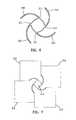
- FIG. 6illustrates a portion of a balloon pleated by the process.
- FIG. 7illustrates a portion of the balloon pleating apparatus.
- FIG. 8is a front, plan view of a balloon pleating system of the present invention.
- FIG. 9is a rear or back plan view of the balloon pleating system of FIG. 8 .
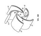
- FIG. 10is an exploded view of a pleating head, utilized in the balloon pleating system of FIGS. 8 and 9 .
- FIG. 11Ais a perspective view of another embodiment of the pleating head, utilized in the balloon pleating system.
- FIG. 11Bis a perspective exploded view of the balloon pleating head of FIG. 11 a.
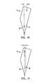
- FIG. 12is a perspective view of an individual segment of the balloon folding head, which shows certain features in phantom.
- FIG. 13is a front view of the segment of FIG. 12 .
- FIG. 14is a side view of the segment.
- FIG. 15is an end view of the segment.
- FIG. 16illustrates an alternative embodiment of a pleating segment of the present invention with a single angle plane and a proximal offset pin aperture.
- FIG. 17illustrates an alternative embodiment of a pleating segment of the present invention with a single angle plane and a proximal offset pin aperture.
- FIG. 18is a diagram that illustrates variations in tip paths of a segment with respect to different pin offset distances from a segment centerline.
- FIG. 19is a front plan view of the balloon folding head with an access aperture in an open position.
- FIG. 20is a front plan view of the balloon folding head of FIG. 19 with the access aperture in a closed position.
- FIG. 21is a front plan view of the balloon folding head of FIG. 19 , with a face plate removed to show the position of internal segments corresponding to the open aperture of FIG. 19 .
- FIG. 22is a front plan view of the balloon folding head of FIGS. 19 and 20 , with the face plate removed to show the position of internal segments corresponding to the closed aperture of FIG. 20 .
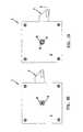
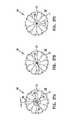
- FIGS. 23A , B and Cshow a sequence of movement of an embodiment of the balloon pleating head, as the pleating aperture proceeds from an open to a closed state, the head embodiment having a proximal offset and being distally driven.
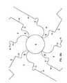
- FIGS. 24A , B and Cshow a sequence of movement of an alternative embodiment of the balloon pleating head, as the pleating aperture proceeds from an open to a closed state, the head embodiment having a proximal offset and being proximally driven.
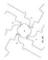
- FIGS. 25A , B and Cshow a sequence of movement of a further alternative embodiment of the balloon pleating head, as the pleating aperture proceeds from an open to a closed state, the head embodiment having a distal offset and being distally driven.
- FIGS. 26A , B and Cshow a sequence of movement of a further alternative embodiment of the balloon pleating head, as the pleating aperture proceeds from an open to a closed state, the head embodiment having a distal offset and being proximally driven.
- FIGS. 27A , B and Cshow a sequence of movement of a further alternative embodiment of the balloon pleating head, as the pleating aperture proceeds from an open to a closed state, the head embodiment having a distal offset and being proximally driven by a drive pin contacting an external surface of the segment.
- FIGS. 28A , B and Cshow a sequence of movement of a further alternative embodiment of the balloon pleating head, as the pleating aperture proceeds from an open to a closed state, the head embodiment having a distal offset and being distally driven by a drive pin, interior the segment, with pivot pins contacting an external surface of the segment.
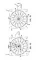
- FIG. 29Ais an enlarged cross sectional view of a pleating head in the open condition, with a balloon in the central pleating aperture.
- FIG. 29Bis an enlarged cross sectional view of a pleating head in a partially closed condition, with a balloon in the central pleating aperture.
- FIG. 29Cis an enlarged cross sectional view of a pleating head in the closed condition, with a balloon in the central pleating aperture.
- FIG. 30Ais an enlarged cross sectional view of a pleating head, with three segments in the closed condition.
- FIG. 30Bis an enlarged sectional view of a portion of a pleated balloon, made with the pleating head of FIG. 30A .
- FIG. 31Ais an enlarged cross sectional view of a pleating head, with four segments in the closed condition.
- FIG. 31Bis an enlarged sectional view of a portion of a pleated balloon, made with the pleating head of FIG. 31A .
- FIG. 32Ais an enlarged cross sectional view of a pleating head, with five segments in the closed condition.
- FIG. 32Bis an enlarged sectional view of a portion of a pleated balloon, made with the pleating head of FIG. 32A .
- FIG. 33is a perspective view of an alternative embodiment of the balloon folding system of the present invention, wherein the balloon pleating head is actuated by a pair of actuators located at the front and back of the head.
- FIG. 34is an exploded view of the pleating head, utilized in the balloon folding system of FIG. 33 .
- FIG. 35is a front view of the balloon pleating head of the embodiment shown in FIGS. 33 and 34 , with the pleating aperture in an open position and the arms in a corresponding position.
- FIG. 36is a front view of the balloon pleating of the dual arm embodiment, with the pleating aperture in a closed position and the arms in a corresponding position.
- FIG. 37is a top view of the balloon pleating head of the dual arm embodiment.
- FIG. 38is a bottom view of the balloon pleating head of the dual arm embodiment.
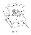
- FIG. 39is a side view of the balloon pleating head of the dual arm embodiment.
- FIG. 40shows a perspective view of an exemplary segment in the dual arm embodiment, having an increased length for longer balloons.
- FIG. 41shows a front view of the segment of FIG. 40 .
- FIG. 42is a perspective view of a balloon pleating and folding system.
- FIG. 43is another perspective view of the balloon pleating and folding system of FIG. 42 .
- FIG. 44is a functional schematic representation of the balloon pleating and folding system of FIG. 42 .
- the balloon-folding processis preferably two steps, in which the first step forms the balloon into a shape with curved wings 210 and angled wing bases 211 (a “spiral-pleated” shape), and the second step folds the balloon tightly around the shaft by means of radial compression through diameter reduction.
- the machine that accomplishes the pleating and folding processincludes a set of pleating elements 212 that move inward toward the balloon, leaving a gap 213 between the elements with the desired spiral-pleat shape.
- a segmental folding mechanismprovided by Machine Solutions, Inc. of Flagstaff, Ariz., USA, preferably, accomplishes the second (folding) step. Radial compression may be accomplished by other means, such as insertion into a sheath and pulling through a tap die.
- the present inventionavoids the problems of the prior art by operating on the entire balloon at once, while applying zero net torque to the balloon, thereby not requiring any adjacent grasping of the balloon or shaft to support torsion and not causing any spiraling of the balloon.
- the machineaccomplishes the process in two steps that we shall call pleating and folding, but both the pleating and folding steps are significantly different from the prior art.
- the first stepis the pleating process, which is done by moving a set of identical, specially shaped elements inward to compress the lightly-inflated balloon. These elements force the balloon into a “spiral-pleat” shape, wherein the wings are curved and the base of the wings are angled and not directed radially outward.
- One specially shaped element contacting a balloonis shown in FIG. 5 . While the elements are holding the balloon, a vacuum is typically applied to the inside of the balloon so that the balloon will retain its “spiral-pleat” shape after the elements are removed, as illustrated in FIG. 6 .
- Four pleating elements in closed positionprovide a “spiral-pleat” shaped central aperture, as seen in FIG. 7 .
- the pleating elementsmay be heated to impart a set to the balloon material to further induce it to retain the spiral-pleated shape after the elements are removed or when positive pressure is applied to the catheter inflation channel.
- the pleating elementsfill the space between the wings as the wings are being formed, thereby applying a zero net torsion to the balloon itself, so that no torsion is required to be applied externally.
- the spiral-pleat shaping of the pleated ballooncauses it to fold predictably, in the desired way, when a subsequent radially-inward compression is applied.
- the next stepis the folding process, in which the spiral-pleated balloon is compressed so that the wings are held close to the catheter shaft. Because of the spiral-pleated shape, the folding is done by radial compression, where the balloon is placed in a circular, cylindrical-shaped opening that reduces its diameter, such as a shrinking tube, a funnel-shaped tube, or a segmental folding mechanism, as supplied by Machine Solutions Inc. of Flagstaff, Ariz. Following or during the compression, the balloon is typically held in the folded position, while being exposed to an elevated temperature for some period of time to impart a set to the balloon so that it will retain the folded shape after removal from the compression mechanism.
- an embodiment of the system 10 for pleating balloons and the likegenerally includes a pleating head 11 , a base 12 , and an actuator 13 .
- the pleating head 11is disposed on the base surface 12 and primarily functions to accept and pleat balloons.
- the actuator 13powers the pleating head.
- the actuator 13preferably includes a drive mechanism 15 , a linkage assembly 16 communicatively connected to the drive mechanism 15 , an actuation arm 17 communicatively connected to the linkage assembly and to the pleating head 11 , and an actuation control system 18 communicatively connected to the drive mechanism 15 .
- the actuator 13may be hand and/or foot operable by an operator.
- the actuator 13is preferably a pneumatic system.
- the base 12is preferably a particularized table structure having a flat work surface of a predetermined area and supported, as shown by supports or legs 14 , a predetermined, optimal distance above the ground for performing the pleating function. It is within the purview of the invention that the pleating head 11 may be disposed on an existing table, bench or other work surface.
- Additional systems, assemblies or mechanismsmay be added to the basic system outlined above. These additional systems include, but are not limited to, handling and alignment control and/or indication devices, pressure regulation and/or indication systems, calibration systems, control devices such as mechanical stops, vision assistance, laser micrometers, vacuum evacuation systems, heating and/or cooling systems, interchangeable pleating heads, and pleating dwell timers. Further, the system 10 may be controlled by an operator or automated.
- the pleating head 11 shownhas a relatively compact, preferably rectilinear, configuration.
- the pleating head 11basically comprises a base or housing 22 , a drive hub 23 , a radial compression wedge 24 , a plurality of pivot pins 25 , a plurality of drive pins 26 , and a face plate or cover 27 .
- the base 22has a predetermined depth or thickness with a wedge chamber 28 , a hub chamber 29 , and a hub aperture 30 .
- the hub 23has a stem portion 31 and a plate portion 32 .
- the wedge 24consists of a plurality of separate segments 33 .
- the cover 27has a centrally disposed aperture 34 .
- the hub 23is constructed of rigid, preferably metallic, material.
- the stem portion 31 of the hub 23has a cylindrical configuration with a predetermined length and circumference, such that it extends through the hub aperture 30 of the base 22 .
- the stem portion 31extends a predetermined distance out of the base 22 and is connected to the actuator arm 17 .
- the actuator arm 17moves in a counter-clockwise direction during actuation to perform a holding, compressing or pleating function.
- the base 22is also constructed of a rigid, preferably metallic, material.
- the plate portion 32 of the hub 23also has a cylindrical configuration with a predetermined depth and circumference, such that it is housed within the hub chamber 29 of the base 22 .
- the hub 23is rotatable with respect to the base 22 .
- the wedge 24has a roughly cylindrical configuration with a predetermined maximum depth and circumference, such that it is housed within the wedge chamber 28 of the base 22 .
- the cooperating depths and circumferences of the wedge 24 and wedge chamber 28respectively, permit the wedge 24 to move within the wedge chamber 28 during a pleating operation.
- the pivot pins 25are constructed of a rigid, preferably metallic, material.
- the pivot pins 25are cylindrical and have a predetermined length and diameter.
- the pivot pins 25are preferably disposed in cylindrical slots or bores 35 in the back wall of the wedge chamber 28 of the base 22 .
- the pins 25are preferably held in the slots 35 via a frictional fit.
- the slots 35are disposed in a circular pattern, equally spaced apart a predetermined distance from each other and from the center of the wedge chamber 28 .
- the drive pins 26are constructed of a rigid, preferably metallic, material and have a cylindrical configuration with a predetermined length and diameter.
- the drive pins 26mate with slots or bores 36 in the plate portion 32 of the hub 23 .
- the drive pins 26preferably, have a slightly smaller horizontal dimension than that of the slots 36 to permit removal of pins 26 therefrom.
- Each slot 36preferably, has a cylindrical configuration which is slightly elongated along an axis extending from the center of the hub 23 .
- the slots 36are disposed in a circular pattern, equally spaced apart a predetermined distance from each other and from the center of the hub 23 .
- the number of pivot pins 25 and drive pins 26is equal to the number of segments 33 in the wedge 24 , and each segment 33 is associated with and pivotally coupled to one pivot pin 25 and one drive pin 26 .
- the pivot pins 25 and drive pins 26mate with corresponding slots or bores in the back face of the wedge segments 33 .
- the pleating head 11comprises a base or housing 22 , a drive hub 23 , a radial compression wedge 24 , a plurality of pivot pins 25 , a plurality of drive pins 26 , and a face plate or cover 27 with central aperture 34 (not shown).
- the base 22has a predetermined depth or thickness with a hub chamber 29 .
- the hub 23is generally cylindrical with a hub central aperture 38 .
- the wedge 24consists of a plurality of separate segments 33 , in this embodiment a total of three.
- the hub 23is constructed of rigid, preferably metallic, material.
- the hub 23has a cylindrical configuration with a predetermined length and circumference, such that it is rotatable in the hub chamber 29 of the base 22 and may ride on a bearing or bushing 39 therein.
- the hub 23is operatively disposed in the hub chamber 29 of the base 22 , its front face is approximately flush with the front surface of the base 22 .
- the hub 23is fastened at its rear face by circumferential enclosure by the actuation arm 17 that positions and supports the hub 23 within the hub chamber 29 of the base 22 .
- the actuator arm 17moves in a counter-clockwise direction, during actuation, to perform a holding, compressing or pleating function.
- the base 22is also constructed of a rigid, preferably metallic material, and the pivot pins 25 are constructed of a rigid, preferably metallic material.
- the pivot pins 25are cylindrical and have a predetermined length and diameter.
- the pivot pins 25are preferably disposed in cylindrical slots or bores 35 in the front face of the base 22 .
- the pins 25are preferably held in the slots 35 via a frictional fit.
- the slots 35are disposed in a circular pattern, equally spaced apart a predetermined distance from each other and from the center of the hub chamber 29 .
- the drive pins 26are constructed of a rigid, preferably metallic, material, and have a cylindrical configuration with a predetermined length and diameter. The drive pins 26 mate with slots or bores 36 in face of the hub 23 .
- the drive pins 26preferably have a slightly smaller horizontal dimension than that of the slots 36 to permit removal of pins 26 therefrom.
- Each slot 36preferably has a cylindrical configuration which is slightly elongated along an axis extending from the center of the hub 23 .
- the slots 36are disposed in a circular pattern, equally spaced apart a predetermined distance from each other and from the center of the hub 23 .
- the drive pins 26are operatively secured to the wedge segments 33 .
- the number of pivot pins 25 and drive pins 26is equal to the number of segments 33 in the wedge 24 , and each wedge 24 is associated with and pivotally coupled to one pivot pin 25 and one drive pin 26 .
- the drive pins 26mate with corresponding slots, or bores, in the back face of the wedge segments 33 and extend there through with a fastener 19 , such as a threaded nut, to rotatably secure the segment 33 to the drive pin 26 .
- the pivot pins 25are disposed exterior the wedge segment 33 , and the segment is biased against the pivot pin 25 by a biasing means, such as a spring.
- Each stop rod 20is positioned to contact a corresponding stop peg 21 fastened to the actuation arm 17 .
- These actuation arm stopsoperate to limit rotational movement of the attached hub 23 and drive pins 26 to control the movement of the segments with respect to the central aperture therein.
- each segment 33preferably has a rectilinear configuration with a proximal end 40 , a distal end 41 , a front face 42 and a rear face 43 .
- a proximal end face 44is preferably flat and rectangular with a predetermined area.
- the distal end 41preferably terminates in a thin edge 45 formed at the intersection of side faces 46 and 47 .
- the distal end 41is shown to have a rectilinear, flat and uniform dimension, with particular dimensions, it may be alternatively configured with a curvilinear, non-flat, textured, and/or non-uniform surfaces, such as stepped geometries and various specialized surface textures, in a variety of dimensions.
- the distal end 41can include a truncated end to provide particular gripping, compression or pleating function, depending upon the article configuration and material.
- the width of edge 45is variable between approximately 5 and 100 mm and is based upon the length of the balloon to be pleated or article to be engaged, held and/or radially compressed.
- both side faces 46 and 47are angled and equivalent.
- FIG. 13shows optional incut portion 53 of face 47 , which face is disposed away from the wedge 24 actuation direction. This provides tip angle tolerance during disactuation of the wedge 24 .
- FIGS. 16 and 17show alternative segment embodiments 53 and 54 , wherein respective single faces 55 and 56 are angled and opposing respective faces 57 and 58 are not angled.
- front face 42has a proximal lower portion 48 and a distally oriented raised or extended portion 49 . A combination of the raised portions 49 of the faces 42 of all of the segments yields center portion 37 . Center portion 37 provides optimum wedge 24 stability with minimal friction.
- Rear face 43has a proximally oriented pivot slot 50 and a distally oriented drive slot 51 .
- the center point of the pivot slot 50is disposed a predetermined distance, “X”, away from a centerline 52 of the segment 33 which runs from the center distal point of the segment 33 (in this embodiment, edge 45 ) to the center proximal point.
- Pivot slot 50has a predetermined vertical depth and cylindrical configuration for mating with the pivot pin 25 , which is coupled to the stationary base 22 .
- the pivot slot 50preferably has a predetermined diameter, which is slightly greater than that of the pivot pin 25 , to permit removal of the pivot pin 25 therefrom.
- the center point of the drive slot 51is disposed on the centerline 52 .
- Drive slot 51has a predetermined vertical depth and cylindrical configuration.
- the drive pin 26is preferably friction fitted into the drive slot 51 .
- each drive pin 26mates with a respective radially elongated cylindrical slot 36 of the rotatable drive hub 23 .
- the radially elongated cylindrical slot 36permits slight radial movement of the drive pin 26 .
- This preferred structureprovides longitudinal or radial clearance for any drive pin 26 which is not creating sufficient geometric offset in relation to an angle plane 46 or 47 of a segment 33 during actuation.
- An acceptable alternative arrangementis to slightly, radially elongate the segment 33 , the drive slot 51 , and to construct the drive hub slot 36 as a circle.
- the pin offset from the centerlineprovides tolerance for movement of the segments 33 through the operating range of the pleating wedge 24 .
- This tolerancepermits opening of the pleating head, the process of which is described below.
- the pivot pin 25 offset distance from the centerline 52preferably ranges from 0.05 to 0.200 inches.
- a preferred pivot pin offset distanceis 0.050 inches for medium and large diameter pleating applications. Larger offset distances provide advantages, such as reduction of tip wear and damage minimization during the pleating of small diameter balloons and other articles.
- the increased pin offset distances from the segment centerlinedecreases required tolerance at the close diameter and less segment friction within the operating range of the pleating head, due to plane shifting. The tip paths of a segment with different pivot pin offsets are shown.
- the exemplary tipis shifted back 0.001 inches.
- the advantage to having the segments interfere at the closed positionis reduced tip flex, which allows the system to pleat onto a small diameter mandrel without segment damage.
- a 0.125 inch offset distanceis preferable to 0.200 inch or higher offset distances, due to large gaps, which will occur in the open position at such offsets.
- the segments 33are preferably constructed of a polymeric material, such as Delrin or Delrin AF, polycarbonate, PEEK or Ertalyte. Alternatively, they may be constructed of a thermoplastic material, a ceramic material, a composite material, or a metallic material such as stainless steel.
- a polymeric materialsuch as Delrin or Delrin AF, polycarbonate, PEEK or Ertalyte.
- theymay be constructed of a thermoplastic material, a ceramic material, a composite material, or a metallic material such as stainless steel.
- the segments 33have a preferred length from the distal to the proximal end of about 1.5 inches, a preferred width of about 0.375 inches and preferred depths or thickness of 0.625 inches minimum, and 0.750 inches maximum.
- the distal slot centeris about 0.441 inches from the distal tip, and the proximal slot center is about 1.375 inches from the distal tip.
- a preferred angle for the angled facesis about twenty-four degrees.
- the wedge 24has an initial, fully open state with a centrally disposed pleating aperture 62 , (best shown in FIGS. 19 and 21 ), a fully closed state, wherein the aperture 62 has a minimum size (best shown in FIGS. 20 and 22 ), and a plurality of intermediate states between the initial fully open state and the fully closed state, wherein the aperture 62 becomes progressively smaller.
- the maximum diameter of the aperture 62is variable, up to approximately 12.0 mm.
- the minimum diameteris also variable, approaching zero.
- the length or depth of the aperture 62is also variable between approximately 1 mm and 100 mm.
- a balloon to be pleated or another article to be engaged and/or radially compressedis inserted and longitudinally advanced a desired distance into the aperture 62 in the initial, open state.
- the balloonis pleated by rotating the actuation arm 17 counter-clockwise, which contracts the aperture 62 . Contraction causes the aperture 62 wall to contact and exert a radially compressive force on the balloon.
- the balloon diameteris reduced a desired amount and engages a catheter body or another structure, as desired, in a balloon manufacturing process.
- the actuator arm 17is held in position for a desired dwell time, typically between 0 and 20 seconds. Subsequently, the actuator arm 17 is rotated clockwise to expand the aperture 62 and release engagement of the balloon.
- the balloon and related structureis retracted and removed from the aperture 62 .
- the pleating aperture 62has a substantially circular, horizontal dimension and a predetermined length, which yields a substantially cylindrical, longitudinal dimension.
- the periphery of the aperture 62radially moves towards the longitudinal center axis 63 of the aperture 62 in a substantially uniform manner, whereby the aperture 62 wall maintains a substantially cylindrical configuration through the closing process.
- Uniform compressionis the result of the interaction, primarily, of the plurality of segments 33 and the pins 25 and 26 , in concert with the respective base 22 and hub 23 .
- the centerlines 52 of the respective segments 33do not radially extend out from the central axis point 63 .
- the centerlines 52converge towards the central axis 63 .
- the centerlines 52extend radially outward from the central axis point 63 . This process brings the distal portions 41 of the segments 33 closer to the center, until, ultimately the distal most portion of each segment, in this embodiment the edges 45 , essentially, contact the central axis point 63 . Due to the symmetry of the wedge 24 elements, each segments behaves identically, and the closure process is highly uniform.
- the above mentioned segmental centerline 52 convergence processresults from pivotal movement of the distal portion 41 of each segment 33 with respect to the stationary proximal portion 40 of the segments 33 .
- the drive hub 23rotates counter clockwise, with respect to the stationary base 22 .
- the distal portions 41 of the segments 33are moved or driven by the drive hub 23 , which is pivotally coupled to each segment 33 by the drive pins 26 , mated with slots 36 and 51 .
- the proximal portions 40 of the segments 33are held in a stationary position, but allowed to pivot, by the base 22 , which is coupled to each segment 33 by the pivot pins 25 mated with slots 35 and 50 .
- the segmental, radial compression apparatus and the process with distally driven, on-centerline drive pins and proximal, off-centerline pivot pinsis further illustrated in FIGS. 23A-C .
- the wedge 70is identical to the wedge 24 of the previous embodiment, except that is has ten segments 71 instead of fifteen. Proximal portions of the segments 71 are pivotally coupled to a stationary base 72 by pivot pins 73 , which are disposed off centerline 78 to the left (towards the direction of drive hub 74 rotation). Distal portions of the segments 71 are coupled to a driven (counter clockwise rotatable) hub 74 by drive pins 75 , which are disposed on centerline 78 .
- FIG. 23Aillustrates a first state with fully open aperture 76 .
- the centerlines 78 of the segments 71are not radially aligned, and the distal most points of the segments are spaced from wedge's central axis.
- FIG. 23Billustrates a second, intermediate state wherein the hub 74 is traveling.
- the centerlines of the segments 71are still not radially aligned.
- the distal most points of the segmentsare approaching the wedge's central axis 77 .
- FIG. 23Cillustrates a final state, where the aperture is closed.
- the centerlines of the segments 71are aligned and radiate from the central axis 77 .
- the apertureis fully closed.
- FIGS. 24A-Cillustrates an alternative embodiment of the segmental, radial compression apparatus and the process of the present invention with proximally driven, off-centerline drive pins and distal, on-centerline pivot pins.
- the wedge 80has ten segments 81 . Proximal portions of the segments 81 are coupled to a driven (clockwise rotatable) plate 82 by drive pins 83 , which are disposed off centerline 88 to the left (against the direction of drive plate 82 rotation). Distal portions of the segments 81 are pivotally coupled to a stationary hub 84 by pivot pins 85 , which are disposed on centerline 88 .
- FIG. 24Aillustrates a first state with a fully open aperture 86 .
- the centerlines 88 of the segments 81are not radially aligned, and the distal most points of the segments 81 are spaced from the wedge's central axis 87 .
- FIG. 24Billustrates a second, intermediate state wherein, the hub 84 is traveling.
- the centerlines of the segments 81are still not radially aligned.
- the distal most points of the segmentsare approaching the wedge's central axis 87 .
- FIG. 24Cillustrates a final state where the aperture is closed.
- the centerlines of the segments 81are aligned and radiate from the central axis 87 .
- the apertureis fully closed.
- FIGS. 25A-Cillustrates an alternative embodiment of the segmental, radial compression apparatus and the process of the present invention with distally driven, off-centerline drive pins and proximal, on-centerline pivot pins.
- the wedge 90has ten segments 91 . Proximal portions of the segments 91 are pivotally coupled to a stationary base 92 by pivot pins 93 , which are disposed on centerline 98 .
- the pivot pins 93are permitted a slight amount of radial movement, with respect to the stationary base 92 or to the segment 91 , via elongated slotting, previously described.
- FIG. 25Aillustrates a first state with a fully open aperture 96 .
- the centerlines 98 of the segments 91are not radially aligned, and the distal most points of the segments 91 are spaced from wedge's central axis.
- FIG. 25Billustrates a second, intermediate state wherein the hub 94 is traveling.
- the centerlines of the segments 91are still not radially aligned.
- the distal most points of the segmentsare approaching wedge's central axis 89 .
- FIG. 25Cillustrates a final state, where the aperture is closed.
- the centerlines of the segments 91are aligned and radiate from the central axis 89 .
- the apertureis fully closed.
- FIGS. 26A-Cillustrates an alternative embodiment of the segmental, radial compression apparatus and the process of the present invention with proximally driven, on-centerline drive pins and distal, off-centerline pivot pins.
- the wedge 100has ten segments 101 . Proximal portions of the segments 101 are coupled to a driven (clockwise rotatable) plate 102 by drive pins 103 , which are disposed on centerline 108 .
- the drive pins 103are permitted a slight amount of radial movement with respect to the driven plate 102 or to the segment 101 , via elongated slotting, previously described.
- FIG. 26Aillustrates a first state with a fully open aperture 106 .
- the centerlines 108 of the segments 101are not radially aligned, and the distal most points of the segments 101 are spaced from the wedge's central axis.
- FIG. 26Billustrates a second, intermediate state wherein the hub 104 is traveling.
- the centerlines of the segments 101are still not radially aligned.
- the distal most points of the segmentsare approaching the wedge's central axis 107 .
- FIG. 26Cillustrates a final state, where the aperture is closed.
- the centerlines of the segments 101are aligned and radiate from the central axis 107 .
- the apertureis fully closed.
- FIGS. 27A-Cillustrates an alternative embodiment of the segmental, radial compression apparatus and the process of the present invention with proximally driven, off-centerline drive pins, which are disposed laterally to the side of the segments and distal, off-centerline pivot pins.
- the wedge 110has ten segments 111 . Proximal portions of the segments 111 are driven (clockwise rotatable), via plate 112 by drive pins 113 , which are disposed off centerline 118 . In this embodiment, in contrast to the embodiments shown in FIGS. 26A-C , the drive pins 113 are not captured by slots in the body portions of the segments 111 .
- FIG. 27Aillustrates a first state with fully open aperture 116 .
- the centerlines 118 of the segments 111are not radially aligned, and the distal most points of the segments 111 are spaced from the wedge's central axis.
- FIG. 27Billustrates a second, intermediate state, wherein the hub 114 is traveling. The centerlines of the segments 111 are still not radially aligned.
- FIG. 27Cillustrates a final state where the aperture is closed.
- the centerlines of the segments 111are aligned and radiate from the central axis 117 .
- the apertureis fully closed.
- FIGS. 28A-Cillustrates an alternative embodiment of the segmental, radial compression apparatus and the process of the present invention with distally driven, off-centerline drive pins, which are disposed laterally to the side of the segments and proximal, off-centerline pivot pins.
- the wedge 120has ten segments 121 . Distal portions of the segments 121 are coupled to a driven (counter-clockwise rotatable) hub 122 by drive pins 123 , which are disposed off centerline 128 . Proximal portions of the segments 121 are pivotally coupled to a stationary plate 124 by pivot pins 125 , which are disposed off centerline 128 . In this embodiment, in contrast to the embodiments shown in FIGS.
- FIG. 28Aillustrates a first state with fully open aperture 126 .
- the centerlines 128 of the segments 121are not radially aligned, and the distal most points of the segments 121 are spaced from the wedge's central axis.
- FIG. 28Billustrates a second, intermediate state wherein the hub 122 is traveling.
- the centerlines of the segments 121are still not radially aligned.
- the distal most points of the segmentsare approaching the wedge's central axis 127 .
- FIG. 28Cillustrates a final state where the aperture is closed.
- the centerlines of the segments 121are aligned and radiate from the central axis 127 .
- the apertureis fully closed.
- FIGS. 29A-29Can enlarged cross sectional view of a pleating head 11 having four segments 33 , with a balloon in the central pleating aperture 62 , is shown.
- Each segment distal end 41is identical and has a curvilinear structure with a curved projecting end 130 having a point 131 , which first contacts the balloon surface.
- the curved projecting end 130extends the full length of the balloon, and the point 131 represents a thin linear surface that contacts the balloon along its complete length, or nearly so.
- Each distal end 41also has stop surfaces 132 and 133 and contact surfaces 134 , 135 .
- the drive pins 26pivot the segments to move the distal ends 41 closer to the pleating head 11 center point.
- 29Adepicts the condition where the point 131 of the curved projecting end 130 of each segment distal end 41 contacts the balloon surface.
- the point 131 of segment distal end 41begins to pleat the balloon, as depicted in FIG. 29B .
- FIG. 29CWith the pleating head 11 in the fully closed condition, the stop surface 132 of each segment 33 abuts the stop surface 133 on an adjacent segment 33 to prevent further movement of the distal ends 41 , closer to the pleating head 11 center point.
- the contact surface 134 of each segment 33tangentially approaches and meets a contact surface 135 of an adjacent segment 33 .
- each segment 33With the stop surface 132 of each segment 33 in abutment contact with the stop surface 133 of an adjacent segment 33 , and the contact surfaces 134 of each segment 33 meeting a contact surface 135 of an adjacent segment 33 , the curved projecting end 130 can move no nearer the center point, and pleating ceases.
- the stops 132 , 133are positioned so that each curved projecting end 130 of the segment distal end 41 only approaches an adjacent curved projecting end 130 , leaving a curved channel 136 there between, as seen in FIG. 29C .
- This structural feature of the segment's distal end 41pleats the balloon in a spiral pattern having, in this embodiment, four wings 137 all in a similar curved configuration, with the base 138 of each wing angled relative to the balloon core.
- FIG. 30AAn enlarged cross sectional view of a pleating head 11 , having three segments 33 in a fully closed condition, is depicted in FIG. 30A .
- the central aperture with three spiral, curved channels 136 extending therefromis readily apparent.
- a section of a spiral-pleated balloon made with the three segment pleating head 11is shown in FIG. 30B .
- Each wing 137 of the pleated balloonis curved in the same direction and the base 138 of each wing is angled, in preparation for folding the spiral-pleated wings to a small volume.
- FIG. 31AAn enlarged cross sectional view of a pleating head 11 , having four segments 33 in a fully closed condition, is depicted in FIG. 31A .
- the central aperture with four spiral, curved channels 136 extending therefromis readily apparent.
- a section of a spiral-pleated balloon made with the four segment pleating head 11is shown in FIG. 31B .
- Each wing 137 of the pleated balloonis curved in the same direction and the base 138 of each wing is angled, in preparation for folding the spiral-pleated wings to a small volume.
- FIG. 32AAn enlarged cross sectional view of a pleating head 11 , having five segments 33 in a fully closed condition, is depicted in FIG. 32A .
- the central aperture with five spiral, curved channels 136 extending therefromis readily apparent.
- a section of a spiral-pleated balloon made with the five segment pleating head 11is shown in FIG. 32B .
- Each wing 137 of the pleated balloonis curved in the same direction, and the base 138 of each wing is angled, in preparation for folding the spiral-pleated wings to a small volume.
- spiral-pleated wings 137that can be prepared for a balloon is limited only by the number of wedge segments 33 that can be assembled into a pleating head 11 . Segments numbering three to sixteen are contemplated for providing a like number of spiral-pleated wings 137 for a balloon.
- an embodiment of the pleating system 145 for pleating relatively longer balloons and the likegenerally includes a pleating head 146 , a base 147 , and an actuator 148 .
- the pleating head 146is disposed on the base surface 147 and primary functions to accept and pleat balloons.
- the actuator 148powers the pleating head 146 .
- the actuator 148preferably includes a drive mechanism, a linkage assembly communicatively connected to the drive mechanism, actuation arms 149 A and B, which are communicatively connected to the linkage assembly and to the pleating head 146 , and an actuation control system 150 communicatively connected to the drive mechanism.
- the actuator 148may be hand and/or foot operable by an operator.
- the actuator 148is preferably a pneumatic system, although other types of systems may be used.
- the system 145further includes a balloon handling system 152 . Additional systems, assemblies or mechanisms may be added to the basic system 145 .
- the pleating head 146 shownhas a relatively compact, preferably rectilinear, configuration.
- the pleating head 146comprises, basically, a pair of base or housing plates 151 A and B, a pair of drive hubs 153 A and B, a radial compression wedge 154 , two sets (each set including a plurality of pins, preferably 15) of pivot pins 155 A and B, two sets of drive pins 156 A and B, and a pair of separator plates 157 A and B of a predetermined width, which couple the base plates 151 A and B.
- the base plates 151have a predetermined thickness with a central hub apertures 159 A and B.
- the hubs 153have an annular configuration with a flat face portion.
- the wedge 154consists of a plurality of separate segments 160 .
- the hubs 153are constructed of rigid, preferably metallic, material.
- the hubs 153are preferably connected to respective annular roller bearings 161 A and B.
- the hubs 153are connected to respective actuator arms 149 , preferably via respective thrust washers 162 A and B.
- the actuator arms 149move in a counter-clockwise direction during actuation to perform a holding, compressing or pleating function.
- the base plates 151are also constructed of a rigid, preferably metallic, material.
- the hubs 153are rotatable with respect to the base plates 151 .
- the wedge 154has a roughly cylindrical configuration with a predetermined maximum depth and circumference, such that it is housed between the base plates 151 .
- the pivot pins 155 A and Bmate with respective, aligned pivot slots 162 A and B in base plates 151 A and B, and further to respective, aligned pivot slots 165 A and B in the front and rear faces of the segments 160 (at their proximal ends).
- the drive pins 156 A and Bmate with respect, aligned drive slots 163 A and B in the drive hubs 153 A and B, and further to respective, aligned drive slots 166 A and B in the front and rear faces of the segments 160 (at their distal ends).
- System 145functions in a similar manner to that of system 10 , shown in FIGS. 8-10 .
- the actuation arms 149 A and Bare synchronized to move together to apply a uniform force along the entire edge of each of the relatively large wedges 160 .
- the actuation arms 159 A and Bmay be differentially actuated to provide a variable compression along the length of the wedges 160 .
- the pleating apparatus and method of the present inventionis adaptable with thermal capability to operate at temperatures ranging between 37° C. and 300° C., by placing heater cartridges in the segments through its back.
- the balloon pleating devices 10 and 125are adaptable to compensate for thermal expansion.
- the apparatus and methodsare adaptable with cryo capability to operate at temperature ranging between ⁇ 200° C. and ⁇ 37° C. Liquid nitrogen may be used to cool the segments or to cool the housing plates. Alternatively, the entire head may be placed in a cryo chamber.
- the pleating and folding system 170includes a pleating head assembly 171 and a folding head assembly 172 , each disposed on a base unit 173 .
- the head assemblies 171 , 172are coplanar, with central apertures at a common level for ease in consecutive operation.
- An actuator 174 contained within the base unit 173selectively powers the pleating head assembly 171 and the folding head assembly 172 by a suitable drive mechanism 175 connected to each actuation arm 176 and 177 of the head assemblies 171 , 172 , respectively.
- the base unit 173also includes an actuation control system 178 communicatively connected to the drive mechanism 175 for selectively actuating each head assembly.
- the actuator 174is preferably a pneumatic system. Alternatively, hydraulic, mechanical, electrical, or electromechanical actuators may be used, consistent with the basic teachings of the invention. It is within the purview of the invention that the balloon pleating and folding system 170 may be disposed on an existing table, bench or other work surface.
- the balloon handling system 180includes a transport mechanism 181 for moving the support member 181 longitudinally toward each head assembly and laterally between the two head assemblies.
- the support member 181rides on a vertical shaft 183 that extend through a transport slot 184 in the base unit 173 to engage the transport mechanism 182 .
- the slot 184is U-shaped with leg portions aligned with each head assembly and a base portion for movement of the shaft 183 between the two leg portions.
- the support member 181 holding a balloon on a shaftmoves toward the pleating head assembly 171 to insert the balloon therein for the pleating step.
- the support member 181withdraws the pleated balloon from the pleating head assembly 171 , moves to the folding head assembly 172 , inserts the pleated balloon therein for folding, and finally withdraws the pleated and folded balloon on the shaft therefrom.
- FIG. 44is a functional schematic representation of the balloon pleating and folding system 170 .
- the pleating head assembly 171 and the folding head assembly 172are actuated by pneumatic actuators 174 and controlled by an actuation control system 178 .
- Each head assemblyis fitted with individual heaters 190 , connected to separate temperature controllers 191 , for selectively heating each head assembly to set the pleated and folded configuration imparted on the balloon.
- Also included in the schematicis a balloon pressure source 192 and a pressure control 193 for lightly inflating the balloon prior to pleating, and a vacuum source 195 and vacuum control 196 for evacuating the pleated and/or folded balloon, following the pleating and/or folding steps.
- a typical sequence of steps involved in the balloon pleating and folding processis provided in FIG. 44 , as well.
- a balloon handling system 180is also present on the base unit 173 .
- the balloon handling system 180includes a movable support member 181 , adapted for holding a balloon on a shaft and inserting the balloon, consecutively, into the central aperture of the pleating head assembly 171 to spirally pleat the balloon, and then insert the spiral-pleated balloon into the central aperture of the folding head assembly 172 , to fold the balloon spiral wings tightly around the balloon shaft.
- Additional systems, assemblies or mechanismsmay be added to the basic system outlined above. These additional systems include, but are not limited to, handling and alignment control and/or indication devices, pressure regulation and/or indication systems, calibration systems, control devices such as mechanical stops, vision assistance, laser micrometers, vacuum evacuation systems, heating and/or cooling systems, interchangeable pleating heads and folding heads, and pleating or folding dwell timers. Further, the pleating and folding system 170 may be controlled by an operator or automated.
- the pleating head assembly 171 portion of the systemis described in detail with respect to FIGS. 11 a and 11 b above.
- the folding head assembly 172 portion of the systemoperates in the same mode as the pleating head assembly 171 , except that the distal end 41 of each wedge segment 33 is flat to produce a uniform radial compression on the spiral-pleated balloon to affect a tight folding of the balloon wings on the balloon support.
- the folding head assembly 172is described in detail in copending U.S. Patent Application No. 60/210,319, filed Jun. 8, 2000, in the name of Tom Motsenbocker, and entitled, Stent Crimping Device. This application is hereby incorporated by reference as part of the specification.
Landscapes
- Health & Medical Sciences (AREA)
- Heart & Thoracic Surgery (AREA)
- Life Sciences & Earth Sciences (AREA)
- Engineering & Computer Science (AREA)
- Biomedical Technology (AREA)
- General Health & Medical Sciences (AREA)
- Biophysics (AREA)
- Anesthesiology (AREA)
- Child & Adolescent Psychology (AREA)
- Hematology (AREA)
- Animal Behavior & Ethology (AREA)
- Pulmonology (AREA)
- Public Health (AREA)
- Veterinary Medicine (AREA)
- Mechanical Engineering (AREA)
- Media Introduction/Drainage Providing Device (AREA)
- Steroid Compounds (AREA)
- Medicines Containing Antibodies Or Antigens For Use As Internal Diagnostic Agents (AREA)
- Toys (AREA)
Abstract
Description
- i. with a proximal end and an angled distal end with at least one angled side face terminating in an edge of a predetermined length, each segment having a centerline between the proximal and distal ends, each segment having a proximal point and a distal point, one said point being pivotally coupled by pins to the stationary member and one said point being pivotally coupled by pins to the rotatable member;
- ii. the segments being arranged so that the segment distal ends are disposed adjacent to and a predetermined distance away from a central point and defining a central aperture with a spiral-pleat dimension, and that the segment centerlines extending therefrom toward the segment distal ends are oriented away from the central point; and
- iii. the segment distal ends moving closer to the central point upon rotation of the rotatable member in a predetermined direction.
- 1. The segment distal point is on the center line and coupled to the rotatable member, and the segment proximal point is disposed off the centerline and coupled to the stationary member.
- 2. The segment distal point is on the center line and coupled to the stationary member, and the segment proximal point is disposed off the centerline and coupled to the rotatable member.
- 3. The segment distal point is off the center line and coupled to the rotatable member, and the segment proximal point is disposed on the centerline and coupled to the stationary member.
- 4. The segment distal point is off the center line and coupled to the stationary member, and the segment proximal point is disposed on the centerline and coupled to the rotatable member.
- 5. The segment distal point is off the center line and coupled to the rotatable member, and the segment proximal point is disposed off the centerline and coupled to the stationary member.
- 6. The segment distal point is off the center line and coupled to the stationary member, and the segment proximal point is disposed off the centerline and coupled to the rotatable member.
- i. the segments each having a proximal end and an angled distal end with at least one angled side face terminating in an edge of a predetermined length, each segment having a centerline between the proximal and distal ends, each segment having a proximal point and a distal point, the distal point being disposed off the centerline and the proximal point being disposed off the centerline, and the proximal point being pivotally coupled by pins to the stationary base member and the distal point being pivotally coupled by pins to the rotatable hub member;
- ii. the segments being arranged so that the segment distal ends are disposed adjacent to and a predetermined distance away from a central point and defining a central aperture with a spiral-pleat dimension with at least three channels in communication with a central aperture, and that the segment centerlines extending therefrom toward the segment distal ends are oriented away from the central point; and
- iii. the segment distal ends moving closer to the central point upon rotation of the rotatable hub member in a predetermined direction, whereby the balloon is disposed around a shaft substrate, aligned in the central aperture and pleated around the shaft substrate upon rotation of the rotatable hub.
- i. the segments each having a proximal end and an angled distal end with at least one angled side face terminating in an edge of a predetermined length, each segment having a centerline between the proximal and distal ends, each segment having a proximal point and a distal point, the distal point being disposed off the centerline and the proximal point being disposed off the centerline, and the proximal point being pivotally coupled by pins to the stationary base members and the distal point being pivotally coupled by pins to the rotatable hub members;
- ii. the segments being arranged so that the segment distal ends are disposed adjacent to and a predetermined distance away from a central point and defining a central aperture with a spiral-pleat dimension with at least three channels in communication with a central aperture, and that the segment centerlines extending therefrom toward the segment distal ends are oriented away from the central point; and
- iii. the segment distal ends moving closer to the central point upon rotation of the rotatable hub members in a predetermined direction, whereby the balloon is disposed around a shaft substrate, aligned in the central aperture and pleated around the shaft substrate upon rotation of the rotatable hub.
- a. providing an arrangement of a plurality of segments, each having a predetermined shape with a proximal end and an angled distal end, with at least one angled side face terminating in an edge of a predetermined length, each segment having a centerline between the proximal and distal ends, each segment having a proximal point and a distal point, one said point being pivotally coupled by pins to the stationary member and one said point being pivotally coupled by pins to the rotatable member, the segments being arranged so that the segment distal ends are disposed adjacent to and a predetermined distance away from a central point and defining a central aperture with a spiral-pleat dimension, and that the segment centerlines extending therefrom toward the segment distal ends are oriented away from the central point; and
- b. placing a balloon on a shaft substrate;
- c. inserting the balloon and shaft substrate into the central aperture; and
- d. rotating the rotatable member in a predetermined direction so that the segment distal ends move closer to the central point, whereby the central aperture contacts, compresses and pleats the balloon on the shaft substrate.
- A. a balloon pleating head device including:
- i. the segments each having a proximal end and an angled distal end with at least one angled side face terminating in an edge of a predetermined length, each segment having a centerline between the proximal and distal ends, each segment having a proximal point and a distal point, the distal point being disposed off the centerline and the proximal point being disposed off the centerline, and the proximal point being pivotally coupled by pins to the stationary base member and the distal point being pivotally coupled by pins to the rotatable hub member;
- ii. the segments being arranged so that the segment distal ends are disposed adjacent to and a predetermined distance away from a central point and defining a central aperture with a spiral-pleat dimension having at least three channels in communication with a central aperture, and that the segment centerlines extending therefrom toward the segment distal ends are oriented away from the central point; and
- iii. the segment distal ends moving closer to the central point upon rotation of the rotatable hub member in a predetermined direction, whereby the balloon is disposed around a shaft substrate, aligned in the central aperture and pleated around the shaft substrate upon rotation of the rotatable hub; and
- B. a pleated balloon folding device including;
- i. the segments each having a proximal end and an angled distal end with at least one angled side face terminating in an edge of a predetermined length, each segment having a centerline between the proximal and distal ends, each segment having a proximal point and a distal point, the distal point being disposed off the centerline and the proximal point being disposed off the centerline, and the proximal point being pivotally coupled by pins to the stationary base member and the distal point being pivotally coupled by pins to the rotatable hub member;
- ii. the segments being arranged so that the segment distal ends are disposed adjacent to and a predetermined distance away from a central point and defining a central aperture with a cylindrical dimension, and that the segment centerlines extending therefrom toward the segment distal ends are oriented away from the central point; and
- iii. the segment distal ends moving closer to the central point upon rotation of the rotatable hub member in a predetermined direction, whereby the pleated balloon disposed around a shaft substrate, is aligned in the central aperture and folded around the shaft substrate upon rotation of the rotatable hub.
The invention also provides a method of pleating and folding a balloon comprising the steps of: - a. providing a first arrangement of a plurality of segments, each having a predetermined shape with a proximal end and an angled distal end with at least one angled side face terminating in an edge of a predetermined length, each segment having a centerline between the proximal and distal ends, each segment having a proximal point and a distal point, one said point being pivotally coupled by pins to the stationary member and one said point being pivotally coupled by pins to the rotatable member, the segments being arranged so that the segment distal ends are disposed adjacent to and a predetermined distance away from a central point and defining a central aperture with a spiral-pleat dimension, and that the segment centerlines extending therefrom toward the segment distal ends are oriented away from the central point;
- b. providing a second arrangement of a plurality of segments, each having a predetermined shape with a proximal end and an angled distal end with at least one angled side face terminating in an edge of a predetermined length, each segment having a centerline between the proximal and distal ends, each segment having a proximal point and a distal point, and one said point being pivotally coupled by pins to the stationary member and one said point being pivotally coupled by pins to the rotatable member, the segments being arranged so that the segment distal ends are disposed adjacent to and a predetermined distance away from a central point and defining a central aperture with a cylindrical dimension, and that the segment centerlines extending therefrom toward the segment distal ends are oriented away from the central point;
- c. placing a balloon on a shaft substrate;
- d. inserting the balloon and shaft substrate into the first arrangement central aperture;
- e. rotating the rotatable member of the first arrangement in a predetermined direction so that the segment distal ends move closer to the central point, whereby the central aperture contacts, compresses and pleats the balloon onto the shaft substrate to form a pleated balloon;
- f. rotating the rotatable member of the first arrangement in an opposite direction and removing the pleated balloon from the first arrangement;
- g. inserting the pleated balloon and shaft substrate into the second arrangement central aperture;
- h. rotating the rotatable member of the second arrangement in a predetermined direction so that the segment distal ends move closer to the central point, whereby the central aperture contacts, radially compresses and folds the pleated balloon onto the shaft substrate to form a folded balloon; and
- i. rotating the rotatable member of the second arrangement in an opposite direction for removing the folded balloon from the second arrangement.
Claims (5)
Priority Applications (1)
| Application Number | Priority Date | Filing Date | Title |
|---|---|---|---|
| US13/409,398US8679398B2 (en) | 2001-03-26 | 2012-03-01 | Balloon folding technology |
Applications Claiming Priority (4)
| Application Number | Priority Date | Filing Date | Title |
|---|---|---|---|
| US27881701P | 2001-03-26 | 2001-03-26 | |
| US10/107,768US6988881B2 (en) | 2001-03-26 | 2002-03-26 | Balloon folding technology |
| US11/180,875US8128860B2 (en) | 2001-03-26 | 2005-07-13 | Balloon folding technology |
| US13/409,398US8679398B2 (en) | 2001-03-26 | 2012-03-01 | Balloon folding technology |
Related Parent Applications (1)
| Application Number | Title | Priority Date | Filing Date |
|---|---|---|---|
| US11/180,875ContinuationUS8128860B2 (en) | 2001-03-26 | 2005-07-13 | Balloon folding technology |
Publications (2)
| Publication Number | Publication Date |
|---|---|
| US20130056907A1 US20130056907A1 (en) | 2013-03-07 |
| US8679398B2true US8679398B2 (en) | 2014-03-25 |
Family
ID=23066492
Family Applications (5)
| Application Number | Title | Priority Date | Filing Date |
|---|---|---|---|
| US10/107,768Expired - LifetimeUS6988881B2 (en) | 2001-03-26 | 2002-03-26 | Balloon folding technology |
| US11/180,146Expired - LifetimeUS7407377B2 (en) | 2001-03-26 | 2005-07-13 | Balloon folding technology |
| US11/180,875Expired - LifetimeUS8128860B2 (en) | 2001-03-26 | 2005-07-13 | Balloon folding technology |
| US11/206,164AbandonedUS20050277877A1 (en) | 2001-03-26 | 2005-08-17 | Balloon technology |
| US13/409,398Expired - LifetimeUS8679398B2 (en) | 2001-03-26 | 2012-03-01 | Balloon folding technology |
Family Applications Before (4)
| Application Number | Title | Priority Date | Filing Date |
|---|---|---|---|
| US10/107,768Expired - LifetimeUS6988881B2 (en) | 2001-03-26 | 2002-03-26 | Balloon folding technology |
| US11/180,146Expired - LifetimeUS7407377B2 (en) | 2001-03-26 | 2005-07-13 | Balloon folding technology |
| US11/180,875Expired - LifetimeUS8128860B2 (en) | 2001-03-26 | 2005-07-13 | Balloon folding technology |
| US11/206,164AbandonedUS20050277877A1 (en) | 2001-03-26 | 2005-08-17 | Balloon technology |
Country Status (7)
| Country | Link |
|---|---|
| US (5) | US6988881B2 (en) |
| EP (1) | EP1372924B1 (en) |
| JP (1) | JP2004525704A (en) |
| AT (1) | ATE369890T1 (en) |
| CA (1) | CA2441946C (en) |
| DE (1) | DE60221810D1 (en) |
| WO (1) | WO2002076700A1 (en) |
Cited By (1)
| Publication number | Priority date | Publication date | Assignee | Title |
|---|---|---|---|---|
| WO2024216196A1 (en)* | 2023-04-14 | 2024-10-17 | Edwards Lifesciences Corporation | Folding mechanism for an introducer sheath |
Families Citing this family (124)
| Publication number | Priority date | Publication date | Assignee | Title |
|---|---|---|---|---|
| US20060271091A1 (en)* | 1995-09-18 | 2006-11-30 | Campbell Carey V | Balloon catheter device |
| US5868704A (en)* | 1995-09-18 | 1999-02-09 | W. L. Gore & Associates, Inc. | Balloon catheter device |
| US7341598B2 (en) | 1999-01-13 | 2008-03-11 | Boston Scientific Scimed, Inc. | Stent with protruding branch portion for bifurcated vessels |
| US7951164B2 (en)* | 2002-02-28 | 2011-05-31 | Boston Scientific Scimed, Inc. | Balloon folding apparatus, methods and products |
| US7758605B2 (en)* | 2002-02-28 | 2010-07-20 | Boston Scientific Scimed, Inc. | Balloon folding apparatus, methods and products |
| US20030187492A1 (en)* | 2002-03-27 | 2003-10-02 | Mchale Tom | Curved wing balloon and manufacture thereof |
| JP2004186100A (en)* | 2002-12-06 | 2004-07-02 | Sanyo Electric Co Ltd | Electroluminescence display device and method of manufacturing the same |
| US7945409B2 (en)* | 2004-01-15 | 2011-05-17 | Icon Interventional Systems, Inc. | Method for verifying position on an angioplasty balloon |
| US7316147B2 (en)* | 2004-01-29 | 2008-01-08 | Boston Scientific Scimed, Inc. | Apparatuses for crimping and loading of intraluminal medical devices |
| US20070073387A1 (en)* | 2004-02-27 | 2007-03-29 | Forster David C | Prosthetic Heart Valves, Support Structures And Systems And Methods For Implanting The Same |
| US20090132035A1 (en)* | 2004-02-27 | 2009-05-21 | Roth Alex T | Prosthetic Heart Valves, Support Structures and Systems and Methods for Implanting the Same |
| CA2813136A1 (en) | 2004-02-27 | 2005-09-15 | Aortx, Inc. | Prosthetic heart valve delivery systems and methods |
| ITTO20040135A1 (en) | 2004-03-03 | 2004-06-03 | Sorin Biomedica Cardio Spa | CARDIAC VALVE PROSTHESIS |
| BRPI0511056A (en)* | 2004-05-14 | 2007-11-27 | Bard Inc C R | gastric balloon devices and methods of use |
| ES2310357T3 (en)* | 2004-05-21 | 2009-01-01 | Medtronic Vascular, Inc. | BALLED BALLOONS FOR CATETER. |
| JP5054524B2 (en) | 2004-06-08 | 2012-10-24 | アドバンスド ステント テクノロジーズ, インコーポレイテッド | Stent with protruding branch for branch pipe |
| US7972351B2 (en)* | 2004-07-13 | 2011-07-05 | Boston Scientific Scimed, Inc. | Balloon folding design and method and apparatus for making balloons |
| US7765670B2 (en)* | 2004-08-13 | 2010-08-03 | Boston Scientific Scimed, Inc. | Method to simultaneously load and cover self expanding stents |
| US20060100689A1 (en)* | 2004-11-10 | 2006-05-11 | Medtronic Vascular, Inc. | Stent crimper with slit sheath |
| US7762804B1 (en) | 2004-12-17 | 2010-07-27 | Interface Associates, Inc. | Balloon catheter folding and wrapping devices and methods |
| ITTO20050074A1 (en) | 2005-02-10 | 2006-08-11 | Sorin Biomedica Cardio Srl | CARDIAC VALVE PROSTHESIS |
| JP2006271678A (en)* | 2005-03-29 | 2006-10-12 | Naka Eco Keiei Kenkyusho:Kk | Balloon catheter, production method of balloon catheter, forming apparatus for wing element of balloon part, and winding apparatus for balloon part |
| US7530253B2 (en)* | 2005-09-09 | 2009-05-12 | Edwards Lifesciences Corporation | Prosthetic valve crimping device |
| US20070112300A1 (en)* | 2005-11-14 | 2007-05-17 | Roman Ricardo D | Balloon folding design, apparatus and method of making the same |
| JP2009519770A (en) | 2005-12-16 | 2009-05-21 | インターフェイス・アソシエイツ・インコーポレーテッド | Medical multilayer balloon and method for producing the same |
| US7540881B2 (en) | 2005-12-22 | 2009-06-02 | Boston Scientific Scimed, Inc. | Bifurcation stent pattern |
| US9078781B2 (en) | 2006-01-11 | 2015-07-14 | Medtronic, Inc. | Sterile cover for compressible stents used in percutaneous device delivery systems |
| US8147541B2 (en) | 2006-02-27 | 2012-04-03 | Aortx, Inc. | Methods and devices for delivery of prosthetic heart valves and other prosthetics |
| US7749266B2 (en) | 2006-02-27 | 2010-07-06 | Aortx, Inc. | Methods and devices for delivery of prosthetic heart valves and other prosthetics |
| US8585594B2 (en) | 2006-05-24 | 2013-11-19 | Phoenix Biomedical, Inc. | Methods of assessing inner surfaces of body lumens or organs |
| US8500799B2 (en) | 2006-06-20 | 2013-08-06 | Cardiacmd, Inc. | Prosthetic heart valves, support structures and systems and methods for implanting same |
| EP2035723A4 (en) | 2006-06-20 | 2011-11-30 | Aortx Inc | Torque shaft and torque drive |
| CN101505668A (en)* | 2006-06-20 | 2009-08-12 | 奥尔特克斯公司 | Prosthetic valve implant site preparation techniques |
| WO2007149933A2 (en) | 2006-06-21 | 2007-12-27 | Aortx, Inc. | Prosthetic valve implantation systems |
| US8020277B2 (en) | 2006-07-28 | 2011-09-20 | Cook Medical Technologies Llc | Apparatus for compressing an expandable medical device |
| US7896642B2 (en)* | 2006-08-03 | 2011-03-01 | Boston Scientific Scimed, Inc. | Balloon folding device |
| US9180279B2 (en) | 2006-08-07 | 2015-11-10 | W. L. Gore & Associates, Inc. | Inflatable imbibed polymer devices |
| US7785290B2 (en) | 2006-08-07 | 2010-08-31 | Gore Enterprise Holdings, Inc. | Non-shortening high angle wrapped balloons |
| US20080140173A1 (en) | 2006-08-07 | 2008-06-12 | Sherif Eskaros | Non-shortening wrapped balloon |
| US8460240B2 (en) | 2006-08-07 | 2013-06-11 | W. L. Gore & Associates, Inc. | Inflatable toroidal-shaped balloons |
| US20080097300A1 (en)* | 2006-08-07 | 2008-04-24 | Sherif Eskaros | Catheter balloon with multiple micropleats |
| US20080125711A1 (en) | 2006-08-07 | 2008-05-29 | Alpini Alfred A | Catheter balloons with integrated non-distensible seals |
| US20080140174A1 (en)* | 2006-08-17 | 2008-06-12 | Abbott Laboratories | Method of increasing balloon flexibility in a balloon catheter |
| US7963142B2 (en)* | 2006-08-22 | 2011-06-21 | Ed Goff | Radial compression mechanism with optimum die-to-die gap |
| US20080051707A1 (en) | 2006-08-25 | 2008-02-28 | Phan Christopher U | Apparatus and methods for use of expandable members in surgical applications |
| US8926620B2 (en) | 2006-08-25 | 2015-01-06 | Kyphon Sarl | Apparatus and methods for use of expandable members in surgical applications |
| US8609016B2 (en) | 2006-08-28 | 2013-12-17 | Boston Scientific Scimed, Inc. | Refoldable balloon and method of making and using the same |
| JP2010502395A (en)* | 2006-09-06 | 2010-01-28 | エーオーテックス, インコーポレイテッド | Prosthetic heart valve, implantation system and method |
| US8323325B2 (en)* | 2006-09-25 | 2012-12-04 | Boston Scientific Scimed, Inc. | Balloon with wings for rotational stent |
| US7951191B2 (en) | 2006-10-10 | 2011-05-31 | Boston Scientific Scimed, Inc. | Bifurcated stent with entire circumferential petal |
| US8088100B2 (en)* | 2006-10-20 | 2012-01-03 | Boston Scientific Scimed, Inc. | Reinforced rewrappable balloon |
| US7618252B1 (en)* | 2006-10-24 | 2009-11-17 | Ed Goff | Balloon pleating mechanism |
| US7842082B2 (en) | 2006-11-16 | 2010-11-30 | Boston Scientific Scimed, Inc. | Bifurcated stent |
| WO2008095052A2 (en) | 2007-01-30 | 2008-08-07 | Loma Vista Medical, Inc., | Biological navigation device |
| US7896840B2 (en)* | 2007-04-05 | 2011-03-01 | Boston Scientific Scimed, Inc. | Catheter having internal mechanisms to encourage balloon re-folding |
| US20080262603A1 (en)* | 2007-04-23 | 2008-10-23 | Sorin Biomedica Cardio | Prosthetic heart valve holder |
| US8006535B2 (en)* | 2007-07-12 | 2011-08-30 | Sorin Biomedica Cardio S.R.L. | Expandable prosthetic valve crimping device |
| US7942661B2 (en)* | 2007-07-18 | 2011-05-17 | Boston Scientific Scimed, Inc. | Bifurcated balloon folding method and apparatus |
| US7959669B2 (en) | 2007-09-12 | 2011-06-14 | Boston Scientific Scimed, Inc. | Bifurcated stent with open ended side branch support |
| US8046897B2 (en) | 2007-09-28 | 2011-11-01 | Abbott Cardiovascular Systems Inc. | Method and apparatus for stent retention on a balloon catheter |
| US9848981B2 (en) | 2007-10-12 | 2017-12-26 | Mayo Foundation For Medical Education And Research | Expandable valve prosthesis with sealing mechanism |
| US7833266B2 (en) | 2007-11-28 | 2010-11-16 | Boston Scientific Scimed, Inc. | Bifurcated stent with drug wells for specific ostial, carina, and side branch treatment |
| US8277501B2 (en) | 2007-12-21 | 2012-10-02 | Boston Scientific Scimed, Inc. | Bi-stable bifurcated stent petal geometry |
| US8932340B2 (en) | 2008-05-29 | 2015-01-13 | Boston Scientific Scimed, Inc. | Bifurcated stent and delivery system |
| US20090299374A1 (en) | 2008-06-02 | 2009-12-03 | Loma Vista Medical, Inc. | Inflatable medical devices |
| US8758422B2 (en)* | 2008-06-11 | 2014-06-24 | Boston Scientific Scimed, Inc. | Edge protection via tapered balloon wrap |
| US8309007B2 (en)* | 2008-08-01 | 2012-11-13 | Boston Scientific Scimed, Inc. | Folding apparatus and methods for bifurcation post-dilatation balloon |
| EP2682072A1 (en) | 2008-12-23 | 2014-01-08 | Sorin Group Italia S.r.l. | Expandable prosthetic valve having anchoring appendages |
| US8715207B2 (en) | 2009-03-19 | 2014-05-06 | Sorin Group Italia S.R.L. | Universal valve annulus sizing device |
| WO2010111621A1 (en)* | 2009-03-26 | 2010-09-30 | Sorin Group Usa, Inc. | Annuloplasty sizers for minimally invasive procedures |
| JP5866668B2 (en)* | 2009-08-28 | 2016-02-17 | メドトロニック 3エフ セラピュティックス インコーポレイテッド | Crimping device and method of use |
| FR2953444B1 (en)* | 2009-12-09 | 2012-01-13 | Michelin Soc Tech | METHOD FOR MANUFACTURING A RING FOR CARRYING OUT A TIRE |
| WO2011119536A1 (en) | 2010-03-22 | 2011-09-29 | Abbott Cardiovascular Systems Inc. | Stent delivery system having a fibrous matrix covering with improved stent retention |
| IT1400327B1 (en) | 2010-05-21 | 2013-05-24 | Sorin Biomedica Cardio Srl | SUPPORT DEVICE FOR VALVULAR PROSTHESIS AND CORRESPONDING CORRESPONDENT. |
| WO2012009486A2 (en) | 2010-07-13 | 2012-01-19 | Loma Vista Medical, Inc. | Inflatable medical devices |
| US9662677B2 (en) | 2010-09-15 | 2017-05-30 | Abbott Laboratories | Drug-coated balloon with location-specific plasma treatment |
| US10188436B2 (en) | 2010-11-09 | 2019-01-29 | Loma Vista Medical, Inc. | Inflatable medical devices |
| US9895517B2 (en) | 2011-01-18 | 2018-02-20 | Loma Vista Medical, Inc. | Inflatable medical devices |
| EP2486894B1 (en) | 2011-02-14 | 2021-06-09 | Sorin Group Italia S.r.l. | Sutureless anchoring device for cardiac valve prostheses |
| ES2641902T3 (en) | 2011-02-14 | 2017-11-14 | Sorin Group Italia S.R.L. | Sutureless anchoring device for cardiac valve prostheses |
| US10010412B2 (en)* | 2011-07-27 | 2018-07-03 | Edwards Lifesciences Corporation | Conical crimper |
| JP5883255B2 (en)* | 2011-09-09 | 2016-03-09 | 株式会社グッドマン | Balloon catheter manufacturing method |
| JP5883254B2 (en)* | 2011-09-09 | 2016-03-09 | 株式会社グッドマン | Balloon catheter manufacturing method |
| US8652145B2 (en) | 2011-12-14 | 2014-02-18 | Edwards Lifesciences Corporation | System and method for crimping a prosthetic valve |
| US9283100B2 (en) | 2012-05-16 | 2016-03-15 | Abbott Cardiovascular Systems Inc. | Polymer scaffold with multi-pleated balloon |
| GB2506160B (en)* | 2012-09-24 | 2014-08-13 | Cook Medical Technologies Llc | Cutting or scoring balloon and apparatus therefor |
| US9724219B2 (en) | 2012-10-04 | 2017-08-08 | Abbott Cardiovascular Systems Inc. | Method of uniform crimping and expansion of medical devices |
| WO2014179505A1 (en)* | 2013-04-30 | 2014-11-06 | Interface Associates, Inc. | Gripping system for straightening a balloon catheter during fluting |
| CN103660264B (en)* | 2013-11-18 | 2015-12-09 | 广州医科大学附属第一医院 | Balloon three-fold folding machine |
| US9757232B2 (en) | 2014-05-22 | 2017-09-12 | Edwards Lifesciences Corporation | Crimping apparatus for crimping prosthetic valve with protruding anchors |
| US10478600B2 (en)* | 2014-05-28 | 2019-11-19 | Machine Solutions, Inc. | Segmental crimper having individually heated crimper segments and method of using the same |
| DE102015104338A1 (en) | 2015-03-23 | 2016-09-29 | Sitevasc Ug | Tubular sleeve and system for the atraumatic treatment of hollow organs |
| WO2017018018A1 (en)* | 2015-07-28 | 2017-02-02 | オリンパス株式会社 | Treatment instrument for endoscope |
| JP6547541B2 (en)* | 2015-09-17 | 2019-07-24 | 日本ゼオン株式会社 | Diameter reduction device |
| JP6639848B2 (en)* | 2015-09-25 | 2020-02-05 | テルモ株式会社 | Balloon folding machine and balloon folding method |
| JP6623014B2 (en)* | 2015-09-25 | 2019-12-18 | テルモ株式会社 | Balloon folding machine and balloon folding method |
| JP6578174B2 (en)* | 2015-09-25 | 2019-09-18 | テルモ株式会社 | Balloon folding machine and balloon folding method |
| JP6545057B2 (en)* | 2015-09-25 | 2019-07-17 | テルモ株式会社 | Balloon folding machine |
| EP3338851B1 (en)* | 2015-09-25 | 2024-01-24 | Terumo Kabushiki Kaisha | Balloon wrapping machine |
| WO2017051878A1 (en)* | 2015-09-25 | 2017-03-30 | テルモ株式会社 | Balloon wrapping machine and balloon wrapping method |
| JP6628532B2 (en)* | 2015-09-25 | 2020-01-08 | テルモ株式会社 | Balloon folding method |
| CN113244507A (en)* | 2015-09-25 | 2021-08-13 | 泰尔茂株式会社 | Sacculus folder |
| US10639147B2 (en) | 2016-06-24 | 2020-05-05 | Edwards Lifesciences Corporation | System and method for crimping a prosthetic valve |
| US10716691B2 (en) | 2016-06-24 | 2020-07-21 | Edwards Lifesciences Corporation | Compact crimping device |
| JP6942711B2 (en)* | 2016-09-23 | 2021-09-29 | テルモ株式会社 | Balloon folding machine |
| US10660773B2 (en) | 2017-02-14 | 2020-05-26 | Abbott Cardiovascular Systems Inc. | Crimping methods for thin-walled scaffolds |
| US11559670B2 (en)* | 2017-05-23 | 2023-01-24 | Ortho-Space Ltd. | Bladder rolling machine |
| JP7246312B2 (en)* | 2017-09-21 | 2023-03-27 | テルモ株式会社 | METHOD AND APPARATUS FOR FORMING DRUG COAT LAYER |
| WO2019069145A1 (en) | 2017-10-07 | 2019-04-11 | Sorin Group Italia S.R.L. | Bendable cardiac surgery instruments |
| US10555825B2 (en) | 2017-11-09 | 2020-02-11 | Abbott Cardiovascular Systems Inc. | Rotation of a medical device during crimping |
| US10668247B2 (en) | 2017-11-15 | 2020-06-02 | Alcyone Lifesciences, Inc. | Therapy specific, pre-programmed auto injection device |
| PT3787561T (en) | 2018-04-30 | 2022-05-27 | Edwards Lifesciences Corp | DEVICES FOR CRIMPING PROSTHETIC IMPLANTS |
| CN112437648B (en) | 2018-05-23 | 2024-08-09 | 恪心有限责任公司 | Holder for a heart valve prosthesis, storage device for a heart valve prosthesis, and crimping kit and method |
| JP7170127B2 (en) | 2018-05-23 | 2022-11-11 | コーシム・ソチエタ・ア・レスポンサビリタ・リミタータ | Loading system and associated loading method for implantable prostheses |
| JP7074930B2 (en) | 2018-05-23 | 2022-05-24 | コーシム・ソチエタ・ア・レスポンサビリタ・リミタータ | Device for in-situ delivery of heart valve prosthesis |
| AU2018424859B2 (en) | 2018-05-23 | 2024-04-04 | Corcym S.R.L. | A cardiac valve prosthesis |
| US10967556B2 (en) | 2018-06-11 | 2021-04-06 | Abbott Cardiovascular Systems Inc. | Uniform expansion of thin-walled scaffolds |
| JP7394836B2 (en)* | 2019-03-22 | 2023-12-08 | テルモ株式会社 | balloon folding device |
| JPWO2020196229A1 (en) | 2019-03-22 | 2020-10-01 | ||
| EP3922217A1 (en) | 2020-06-05 | 2021-12-15 | BVS - Best Vascular Solutions GmbH | Tubular non-woven structure as an active substance carrier for atraumatic treatment of hollow organs and a method for its production |
| DE102020117801A1 (en) | 2020-06-05 | 2021-12-09 | Bvs - Best Vascular Solutions Gmbh | Tubular fleece structure as an active substance carrier for the atraumatic treatment of hollow organs and a method for production |
| PL4203851T3 (en) | 2020-08-31 | 2025-06-23 | Edwards Lifesciences Corporation | Systems and methods for crimping and device preparation |
| WO2024018082A1 (en) | 2022-07-22 | 2024-01-25 | Bvs - Best Vascular Solutions Gmbh | Balloon catheter device for atraumatic expansion of hollow organs, and a method for producing such a balloon catheter device |
| DE102022122630A1 (en) | 2022-07-22 | 2024-01-25 | Bvs - Best Vascular Solutions Gmbh | Balloon catheter device for the atraumatic treatment of hollow organs and a method for producing such a balloon catheter device |
Citations (79)
| Publication number | Priority date | Publication date | Assignee | Title |
|---|---|---|---|---|
| US1665915A (en) | 1925-12-21 | 1928-04-10 | Albert C Ekman | Pipe-swaging device |
| US1889795A (en) | 1928-12-04 | 1932-12-06 | Frank H Smith | Method of joining pipes |
| US2292421A (en) | 1938-09-08 | 1942-08-11 | United Metal Hose Company Inc | Hose coupling-method of and means for forming same |
| US2751077A (en) | 1952-05-23 | 1956-06-19 | Okonite Co | Extrusion apparatus for sheathing electric cables |
| US2887222A (en) | 1956-03-23 | 1959-05-19 | Okonite Co | Extrusion apparatus for sheathing electric cables |
| US3664213A (en) | 1969-09-11 | 1972-05-23 | Reuven Anati | Wrench |
| US3695087A (en) | 1970-08-26 | 1972-10-03 | Arthur H Tuberman | Method and apparatus for pointing tubes |
| US4413989A (en) | 1980-09-08 | 1983-11-08 | Angiomedics Corporation | Expandable occlusion apparatus |
| US4456000A (en) | 1981-08-17 | 1984-06-26 | Angiomedics Corporation | Expandable occlusion apparatus |
| US4490421A (en) | 1983-07-05 | 1984-12-25 | E. I. Du Pont De Nemours And Company | Balloon and manufacture thereof |
| US4578982A (en) | 1983-09-02 | 1986-04-01 | Schroeck Peter | Radial press for workpieces having a cylindrical exterior surface |
| US4681092A (en) | 1985-05-21 | 1987-07-21 | Kontron Inc. | Balloon catheter wrapping apparatus |
| USRE32983E (en) | 1983-07-05 | 1989-07-11 | E. I. Du Pont De Nemours And Company | Balloon and manufacture thereof |
| US4854031A (en) | 1989-02-09 | 1989-08-08 | The Goodyear Tire & Rubber Company | Hose crimper and method of using same |
| US4906244A (en) | 1988-10-04 | 1990-03-06 | Cordis Corporation | Balloons for medical devices and fabrication thereof |
| USRE33561E (en) | 1983-07-05 | 1991-03-26 | E. I. Du Pont De Nemours And Company | Balloon and manufacture thereof |
| US5026377A (en) | 1989-07-13 | 1991-06-25 | American Medical Systems, Inc. | Stent placement instrument and method |
| US5087394A (en) | 1989-11-09 | 1992-02-11 | Scimed Life Systems, Inc. | Method for forming an inflatable balloon for use in a catheter |
| US5108415A (en) | 1988-10-04 | 1992-04-28 | Cordis Corporation | Balloons for medical devices and fabrication thereof |
| US5156612A (en) | 1988-10-04 | 1992-10-20 | Cordis Corporation | Balloons for medical devices and fabrication thereof |
| US5163989A (en) | 1990-08-27 | 1992-11-17 | Advanced Cardiovascular Systems, Inc. | Method for forming a balloon mold and the use of such mold |
| US5183085A (en) | 1991-09-27 | 1993-02-02 | Hans Timmermans | Method and apparatus for compressing a stent prior to insertion |
| US5195350A (en) | 1991-04-25 | 1993-03-23 | E. I. Du Pont De Nemours And Company | Method for forming features on an elongated metal wire |
| US5209799A (en) | 1992-04-17 | 1993-05-11 | Inverventional Technologies, Inc. | Method for manufacturing a folding balloon catheter |
| US5261263A (en) | 1992-12-21 | 1993-11-16 | Whitesell Eric J | Crimping pliers with radially opposed jaws |
| US5270086A (en) | 1989-09-25 | 1993-12-14 | Schneider (Usa) Inc. | Multilayer extrusion of angioplasty balloons |
| US5290305A (en) | 1991-10-11 | 1994-03-01 | Kanji Inoue | Appliance collapsible for insertion into human organs and capable of resilient restoration |
| US5304340A (en) | 1991-09-06 | 1994-04-19 | C. R. Bard, Inc. | Method of increasing the tensile strength of a dilatation balloon |
| US5334146A (en) | 1990-11-10 | 1994-08-02 | Terumo Kabushiki Kaisha | Catheter balloon having varying wall thickness |
| US5350361A (en) | 1993-11-10 | 1994-09-27 | Medtronic, Inc. | Tri-fold balloon for dilatation catheter and related method |
| US5358486A (en) | 1987-01-09 | 1994-10-25 | C. R. Bard, Inc. | Multiple layer high strength balloon for dilatation catheter |
| EP0630623A2 (en) | 1993-05-24 | 1994-12-28 | Advanced Cardiovascular Systems, Inc. | Mechanism for loading a stent on a catheter |
| US5381686A (en) | 1994-03-03 | 1995-01-17 | Coherent Inc. | Dual-action pneumo-hydraulic crimping apparatus |
| US5411521A (en) | 1992-03-04 | 1995-05-02 | American Cyanamid Company | Medical suturing device, a single-strike die mechanism, and a method of using said die mechanism for forming the medical suturing device |
| DE29506654U1 (en) | 1995-04-19 | 1995-06-08 | Hurtado Artozon, Roberto, Dr.med., 46047 Oberhausen | Spreader for stents |
| WO1996003092A1 (en) | 1994-07-28 | 1996-02-08 | Brun, Heidi, M. | A flexible expandable stent |
| EP0701800A1 (en) | 1994-09-15 | 1996-03-20 | C.R. Bard, Inc. | Method and apparatus for recapture of hooked endoprosthesis |
| US5509184A (en) | 1993-02-19 | 1996-04-23 | Trouvay & Cauvin S.A. | Apparatus for crimping a tube in a thick panel |
| US5591222A (en) | 1991-10-18 | 1997-01-07 | Susawa; Takashi | Method of manufacturing a device to dilate ducts in vivo |
| DE19532288A1 (en) | 1995-09-01 | 1997-03-06 | Ulrich Dipl Phys Dr M Solzbach | Aid for applying stent on balloon of dilation catheter |
| US5626604A (en) | 1995-12-05 | 1997-05-06 | Cordis Corporation | Hand held stent crimping device |
| US5628754A (en) | 1995-08-01 | 1997-05-13 | Medtronic, Inc. | Stent delivery guide catheter |
| US5630830A (en) | 1996-04-10 | 1997-05-20 | Medtronic, Inc. | Device and method for mounting stents on delivery systems |
| WO1997020593A1 (en) | 1995-12-04 | 1997-06-12 | Cordis Corporation | Stent compression instrument |
| US5700285A (en) | 1993-08-18 | 1997-12-23 | W. L. Gore & Associates, Inc. | Intraluminal stent graft |
| US5725519A (en) | 1996-09-30 | 1998-03-10 | Medtronic Instent Israel Ltd. | Stent loading device for a balloon catheter |
| US5746644A (en) | 1996-02-08 | 1998-05-05 | Royal Master Grinders, Inc. | Centerless grinder assembly and method of operating the same |
| US5749921A (en) | 1996-02-20 | 1998-05-12 | Medtronic, Inc. | Apparatus and methods for compression of endoluminal prostheses |
| WO1998019633A1 (en) | 1996-11-06 | 1998-05-14 | Percusurge, Inc. | Apparatus and method for loading a stent on a catheter |
| US5766203A (en) | 1995-07-20 | 1998-06-16 | Intelliwire, Inc. | Sheath with expandable distal extremity and balloon catheters and stents for use therewith and method |
| US5766057A (en) | 1995-04-19 | 1998-06-16 | Cincinnati Milacron Inc. | Centerless grinding machine |
| US5792172A (en) | 1996-12-23 | 1998-08-11 | Isostent, Inc. | Multifold balloon for stent deployment |
| US5792415A (en) | 1995-03-08 | 1998-08-11 | Cordis Corporation | Method for manufacturing a balloon catheter |
| US5807520A (en) | 1995-11-08 | 1998-09-15 | Scimed Life Systems, Inc. | Method of balloon formation by cold drawing/necking |
| US5810873A (en) | 1997-07-15 | 1998-09-22 | Advanced Cardiovascular Systems, Inc. | Stent crimping tool and method of use |
| US5810871A (en) | 1997-04-29 | 1998-09-22 | Medtronic, Inc. | Stent delivery system |
| US5836952A (en) | 1996-08-21 | 1998-11-17 | Cordis Corporation | Hand-held stent crimper |
| US5836965A (en) | 1994-10-19 | 1998-11-17 | Jendersee; Brad | Stent delivery and deployment method |
| US5860966A (en) | 1997-04-16 | 1999-01-19 | Numed, Inc. | Method of securing a stent on a balloon catheter |
| US5893852A (en) | 1998-04-28 | 1999-04-13 | Advanced Cardiovascular Systems, Inc. | Stent crimping tool and method of use |
| US5911752A (en) | 1996-09-13 | 1999-06-15 | Intratherapeutics, Inc. | Method for collapsing a stent |
| US5931851A (en) | 1998-04-21 | 1999-08-03 | Advanced Cardiovascular Systems, Inc. | Method and apparatus for rubber-tube crimping tool with premount stent |
| EP0935952A2 (en) | 1998-02-17 | 1999-08-18 | Advanced Cardiovascular Systems, Inc. | Stent crimping tool and method of use |
| US5951540A (en) | 1998-10-22 | 1999-09-14 | Medtronic, Inc. | Device and method for mounting stents |
| US5992000A (en) | 1997-10-16 | 1999-11-30 | Scimed Life Systems, Inc. | Stent crimper |
| US6009614A (en) | 1998-04-21 | 2000-01-04 | Advanced Cardiovascular Systems, Inc. | Stent crimping tool and method of use |
| US6018857A (en) | 1997-10-30 | 2000-02-01 | Ave Connaught | Device and method for mounting a stent onto a balloon catheter |
| US6024737A (en) | 1998-02-25 | 2000-02-15 | Advanced Cardiovascular Systems, Inc. | Stent crimping device |
| US6033380A (en) | 1998-02-13 | 2000-03-07 | Cordis Corporation | Six-pleated catheter balloon and device for forming same |
| US6051002A (en) | 1998-10-09 | 2000-04-18 | Advanced Cardiovascular Systems, Inc. | Stent crimping device and method of use |
| US6063102A (en) | 1997-04-22 | 2000-05-16 | Advanced Cardivascular Systems, Inc. | Stent crimping device and method of use |
| US6063092A (en) | 1998-04-07 | 2000-05-16 | Medtronic Inc. | Heat set and crimping process to optimize stent retention |
| US6283743B1 (en) | 1998-03-04 | 2001-09-04 | Scimed Life Systems, Inc. | Balloon wrap device |
| US6296655B1 (en) | 1998-04-27 | 2001-10-02 | Advanced Cardiovascular Systems, Inc. | Catheter balloon with biased multiple wings |
| US6360577B2 (en) | 1999-09-22 | 2002-03-26 | Scimed Life Systems, Inc. | Apparatus for contracting, or crimping stents |
| US6544224B1 (en) | 2000-05-05 | 2003-04-08 | Advanced Cardiovascular Systems, Inc. | Lobed balloon catheter and method of use |
| US6568235B1 (en) | 2000-08-10 | 2003-05-27 | Advanced Cardiovascular Systems, Inc. | Assembly for crimping an intraluminal device or measuring the radial strength of the intraluminal device and method of use |
| US6629350B2 (en) | 2000-06-08 | 2003-10-07 | Tom Motsenbocker | Stent crimping apparatus and method |
| US6706010B1 (en) | 1997-10-08 | 2004-03-16 | Kaneka Corporation | Balloon catheter and method of production thereof |
Family Cites Families (9)
| Publication number | Priority date | Publication date | Assignee | Title |
|---|---|---|---|---|
| US33561A (en)* | 1861-10-22 | Improvement in valves and valve-motions for steam-engines | ||
| US32983A (en)* | 1861-08-06 | Cast-ibon ordnance | ||
| US5087246A (en)* | 1988-12-29 | 1992-02-11 | C. R. Bard, Inc. | Dilation catheter with fluted balloon |
| WO1994023787A1 (en)* | 1993-04-22 | 1994-10-27 | Rammler David H | Sampling balloon catheter |
| US5419911A (en) | 1993-09-28 | 1995-05-30 | Abbott Laboratories | Holder and overcap assembly for a medicated matrix |
| GB9425893D0 (en) | 1994-12-22 | 1995-02-22 | Karobio Ab | Assay apparatus |
| BR9611621A (en) | 1995-11-27 | 1999-04-06 | Siemens Automotive Corp Lp | Bar coding for fuel injector performance data |
| US5672169A (en)* | 1996-04-10 | 1997-09-30 | Medtronic, Inc. | Stent mounting device |
| DE59811867D1 (en)* | 1998-01-22 | 2004-09-30 | Udo Hellwig | Process for shaping bodies by structuring their surface contour |
- 2002
- 2002-03-26WOPCT/US2002/009560patent/WO2002076700A1/enactiveIP Right Grant
- 2002-03-26EPEP02753871Apatent/EP1372924B1/ennot_activeExpired - Lifetime
- 2002-03-26USUS10/107,768patent/US6988881B2/ennot_activeExpired - Lifetime
- 2002-03-26ATAT02753871Tpatent/ATE369890T1/ennot_activeIP Right Cessation
- 2002-03-26CACA2441946Apatent/CA2441946C/ennot_activeExpired - Fee Related
- 2002-03-26JPJP2002575196Apatent/JP2004525704A/enactivePending
- 2002-03-26DEDE60221810Tpatent/DE60221810D1/ennot_activeExpired - Lifetime
- 2005
- 2005-07-13USUS11/180,146patent/US7407377B2/ennot_activeExpired - Lifetime
- 2005-07-13USUS11/180,875patent/US8128860B2/ennot_activeExpired - Lifetime
- 2005-08-17USUS11/206,164patent/US20050277877A1/ennot_activeAbandoned
- 2012
- 2012-03-01USUS13/409,398patent/US8679398B2/ennot_activeExpired - Lifetime
Patent Citations (85)
| Publication number | Priority date | Publication date | Assignee | Title |
|---|---|---|---|---|
| US1665915A (en) | 1925-12-21 | 1928-04-10 | Albert C Ekman | Pipe-swaging device |
| US1889795A (en) | 1928-12-04 | 1932-12-06 | Frank H Smith | Method of joining pipes |
| US2292421A (en) | 1938-09-08 | 1942-08-11 | United Metal Hose Company Inc | Hose coupling-method of and means for forming same |
| US2751077A (en) | 1952-05-23 | 1956-06-19 | Okonite Co | Extrusion apparatus for sheathing electric cables |
| US2887222A (en) | 1956-03-23 | 1959-05-19 | Okonite Co | Extrusion apparatus for sheathing electric cables |
| US3664213A (en) | 1969-09-11 | 1972-05-23 | Reuven Anati | Wrench |
| US3695087A (en) | 1970-08-26 | 1972-10-03 | Arthur H Tuberman | Method and apparatus for pointing tubes |
| US4413989A (en) | 1980-09-08 | 1983-11-08 | Angiomedics Corporation | Expandable occlusion apparatus |
| US4456000A (en) | 1981-08-17 | 1984-06-26 | Angiomedics Corporation | Expandable occlusion apparatus |
| US4490421A (en) | 1983-07-05 | 1984-12-25 | E. I. Du Pont De Nemours And Company | Balloon and manufacture thereof |
| USRE32983E (en) | 1983-07-05 | 1989-07-11 | E. I. Du Pont De Nemours And Company | Balloon and manufacture thereof |
| USRE33561E (en) | 1983-07-05 | 1991-03-26 | E. I. Du Pont De Nemours And Company | Balloon and manufacture thereof |
| US4578982A (en) | 1983-09-02 | 1986-04-01 | Schroeck Peter | Radial press for workpieces having a cylindrical exterior surface |
| US4681092A (en) | 1985-05-21 | 1987-07-21 | Kontron Inc. | Balloon catheter wrapping apparatus |
| US5358486A (en) | 1987-01-09 | 1994-10-25 | C. R. Bard, Inc. | Multiple layer high strength balloon for dilatation catheter |
| US4906244A (en) | 1988-10-04 | 1990-03-06 | Cordis Corporation | Balloons for medical devices and fabrication thereof |
| US5108415A (en) | 1988-10-04 | 1992-04-28 | Cordis Corporation | Balloons for medical devices and fabrication thereof |
| US5156612A (en) | 1988-10-04 | 1992-10-20 | Cordis Corporation | Balloons for medical devices and fabrication thereof |
| US4854031A (en) | 1989-02-09 | 1989-08-08 | The Goodyear Tire & Rubber Company | Hose crimper and method of using same |
| US5026377A (en) | 1989-07-13 | 1991-06-25 | American Medical Systems, Inc. | Stent placement instrument and method |
| US5270086A (en) | 1989-09-25 | 1993-12-14 | Schneider (Usa) Inc. | Multilayer extrusion of angioplasty balloons |
| US5087394A (en) | 1989-11-09 | 1992-02-11 | Scimed Life Systems, Inc. | Method for forming an inflatable balloon for use in a catheter |
| US5163989A (en) | 1990-08-27 | 1992-11-17 | Advanced Cardiovascular Systems, Inc. | Method for forming a balloon mold and the use of such mold |
| US5334146A (en) | 1990-11-10 | 1994-08-02 | Terumo Kabushiki Kaisha | Catheter balloon having varying wall thickness |
| US5195350A (en) | 1991-04-25 | 1993-03-23 | E. I. Du Pont De Nemours And Company | Method for forming features on an elongated metal wire |
| US5304340A (en) | 1991-09-06 | 1994-04-19 | C. R. Bard, Inc. | Method of increasing the tensile strength of a dilatation balloon |
| US5183085A (en) | 1991-09-27 | 1993-02-02 | Hans Timmermans | Method and apparatus for compressing a stent prior to insertion |
| US5290305A (en) | 1991-10-11 | 1994-03-01 | Kanji Inoue | Appliance collapsible for insertion into human organs and capable of resilient restoration |
| US5591222A (en) | 1991-10-18 | 1997-01-07 | Susawa; Takashi | Method of manufacturing a device to dilate ducts in vivo |
| US5411521A (en) | 1992-03-04 | 1995-05-02 | American Cyanamid Company | Medical suturing device, a single-strike die mechanism, and a method of using said die mechanism for forming the medical suturing device |
| US5209799A (en) | 1992-04-17 | 1993-05-11 | Inverventional Technologies, Inc. | Method for manufacturing a folding balloon catheter |
| US5261263A (en) | 1992-12-21 | 1993-11-16 | Whitesell Eric J | Crimping pliers with radially opposed jaws |
| US5509184A (en) | 1993-02-19 | 1996-04-23 | Trouvay & Cauvin S.A. | Apparatus for crimping a tube in a thick panel |
| EP0630623A2 (en) | 1993-05-24 | 1994-12-28 | Advanced Cardiovascular Systems, Inc. | Mechanism for loading a stent on a catheter |
| US5437083A (en) | 1993-05-24 | 1995-08-01 | Advanced Cardiovascular Systems, Inc. | Stent-loading mechanism |
| US5738674A (en) | 1993-05-24 | 1998-04-14 | Advanced Cardiovascular Systems, Inc. | Stent loading mechanism |
| US5546646A (en) | 1993-05-24 | 1996-08-20 | Advanced Cardiovascular Systems, Inc. | Method for mounting an intravascular stent on a catheter |
| US5700285A (en) | 1993-08-18 | 1997-12-23 | W. L. Gore & Associates, Inc. | Intraluminal stent graft |
| US5350361A (en) | 1993-11-10 | 1994-09-27 | Medtronic, Inc. | Tri-fold balloon for dilatation catheter and related method |
| US5381686A (en) | 1994-03-03 | 1995-01-17 | Coherent Inc. | Dual-action pneumo-hydraulic crimping apparatus |
| WO1996003092A1 (en) | 1994-07-28 | 1996-02-08 | Brun, Heidi, M. | A flexible expandable stent |
| EP0701800A1 (en) | 1994-09-15 | 1996-03-20 | C.R. Bard, Inc. | Method and apparatus for recapture of hooked endoprosthesis |
| US5836965A (en) | 1994-10-19 | 1998-11-17 | Jendersee; Brad | Stent delivery and deployment method |
| US5792415A (en) | 1995-03-08 | 1998-08-11 | Cordis Corporation | Method for manufacturing a balloon catheter |
| US5766057A (en) | 1995-04-19 | 1998-06-16 | Cincinnati Milacron Inc. | Centerless grinding machine |
| DE29506654U1 (en) | 1995-04-19 | 1995-06-08 | Hurtado Artozon, Roberto, Dr.med., 46047 Oberhausen | Spreader for stents |
| US5766203A (en) | 1995-07-20 | 1998-06-16 | Intelliwire, Inc. | Sheath with expandable distal extremity and balloon catheters and stents for use therewith and method |
| US5628754A (en) | 1995-08-01 | 1997-05-13 | Medtronic, Inc. | Stent delivery guide catheter |
| DE19532288A1 (en) | 1995-09-01 | 1997-03-06 | Ulrich Dipl Phys Dr M Solzbach | Aid for applying stent on balloon of dilation catheter |
| US5807520A (en) | 1995-11-08 | 1998-09-15 | Scimed Life Systems, Inc. | Method of balloon formation by cold drawing/necking |
| US5746764A (en) | 1995-12-04 | 1998-05-05 | Atrion Medical Products, Inc. | Stent compression instrument |
| WO1997020593A1 (en) | 1995-12-04 | 1997-06-12 | Cordis Corporation | Stent compression instrument |
| US5626604A (en) | 1995-12-05 | 1997-05-06 | Cordis Corporation | Hand held stent crimping device |
| US5746644A (en) | 1996-02-08 | 1998-05-05 | Royal Master Grinders, Inc. | Centerless grinder assembly and method of operating the same |
| US5749921A (en) | 1996-02-20 | 1998-05-12 | Medtronic, Inc. | Apparatus and methods for compression of endoluminal prostheses |
| US5630830A (en) | 1996-04-10 | 1997-05-20 | Medtronic, Inc. | Device and method for mounting stents on delivery systems |
| US5836952A (en) | 1996-08-21 | 1998-11-17 | Cordis Corporation | Hand-held stent crimper |
| US5911752A (en) | 1996-09-13 | 1999-06-15 | Intratherapeutics, Inc. | Method for collapsing a stent |
| US5725519A (en) | 1996-09-30 | 1998-03-10 | Medtronic Instent Israel Ltd. | Stent loading device for a balloon catheter |
| US5893867A (en) | 1996-11-06 | 1999-04-13 | Percusurge, Inc. | Stent positioning apparatus and method |
| WO1998019633A1 (en) | 1996-11-06 | 1998-05-14 | Percusurge, Inc. | Apparatus and method for loading a stent on a catheter |
| US5792172A (en) | 1996-12-23 | 1998-08-11 | Isostent, Inc. | Multifold balloon for stent deployment |
| US5860966A (en) | 1997-04-16 | 1999-01-19 | Numed, Inc. | Method of securing a stent on a balloon catheter |
| US6063102A (en) | 1997-04-22 | 2000-05-16 | Advanced Cardivascular Systems, Inc. | Stent crimping device and method of use |
| US5810871A (en) | 1997-04-29 | 1998-09-22 | Medtronic, Inc. | Stent delivery system |
| US5810873A (en) | 1997-07-15 | 1998-09-22 | Advanced Cardiovascular Systems, Inc. | Stent crimping tool and method of use |
| US6706010B1 (en) | 1997-10-08 | 2004-03-16 | Kaneka Corporation | Balloon catheter and method of production thereof |
| US5992000A (en) | 1997-10-16 | 1999-11-30 | Scimed Life Systems, Inc. | Stent crimper |
| US6018857A (en) | 1997-10-30 | 2000-02-01 | Ave Connaught | Device and method for mounting a stent onto a balloon catheter |
| US6033380A (en) | 1998-02-13 | 2000-03-07 | Cordis Corporation | Six-pleated catheter balloon and device for forming same |
| EP0935952A2 (en) | 1998-02-17 | 1999-08-18 | Advanced Cardiovascular Systems, Inc. | Stent crimping tool and method of use |
| US6024737A (en) | 1998-02-25 | 2000-02-15 | Advanced Cardiovascular Systems, Inc. | Stent crimping device |
| US6283743B1 (en) | 1998-03-04 | 2001-09-04 | Scimed Life Systems, Inc. | Balloon wrap device |
| US6063092A (en) | 1998-04-07 | 2000-05-16 | Medtronic Inc. | Heat set and crimping process to optimize stent retention |
| US6009614A (en) | 1998-04-21 | 2000-01-04 | Advanced Cardiovascular Systems, Inc. | Stent crimping tool and method of use |
| US5931851A (en) | 1998-04-21 | 1999-08-03 | Advanced Cardiovascular Systems, Inc. | Method and apparatus for rubber-tube crimping tool with premount stent |
| US6428568B2 (en) | 1998-04-27 | 2002-08-06 | Advanced Cardiovascular Systems, Inc. | Catheter balloon with biased multiple wings |
| US6296655B1 (en) | 1998-04-27 | 2001-10-02 | Advanced Cardiovascular Systems, Inc. | Catheter balloon with biased multiple wings |
| US5893852A (en) | 1998-04-28 | 1999-04-13 | Advanced Cardiovascular Systems, Inc. | Stent crimping tool and method of use |
| US6051002A (en) | 1998-10-09 | 2000-04-18 | Advanced Cardiovascular Systems, Inc. | Stent crimping device and method of use |
| US5951540A (en) | 1998-10-22 | 1999-09-14 | Medtronic, Inc. | Device and method for mounting stents |
| US6360577B2 (en) | 1999-09-22 | 2002-03-26 | Scimed Life Systems, Inc. | Apparatus for contracting, or crimping stents |
| US6544224B1 (en) | 2000-05-05 | 2003-04-08 | Advanced Cardiovascular Systems, Inc. | Lobed balloon catheter and method of use |
| US6629350B2 (en) | 2000-06-08 | 2003-10-07 | Tom Motsenbocker | Stent crimping apparatus and method |
| US6568235B1 (en) | 2000-08-10 | 2003-05-27 | Advanced Cardiovascular Systems, Inc. | Assembly for crimping an intraluminal device or measuring the radial strength of the intraluminal device and method of use |
Non-Patent Citations (1)
| Title |
|---|
| Information concerning Conception and Reduction to Practice contained on the IDS. |
Cited By (1)
| Publication number | Priority date | Publication date | Assignee | Title |
|---|---|---|---|---|
| WO2024216196A1 (en)* | 2023-04-14 | 2024-10-17 | Edwards Lifesciences Corporation | Folding mechanism for an introducer sheath |
Also Published As
| Publication number | Publication date |
|---|---|
| CA2441946A1 (en) | 2002-10-03 |
| CA2441946C (en) | 2010-02-23 |
| EP1372924A4 (en) | 2006-04-12 |
| EP1372924A1 (en) | 2004-01-02 |
| US20050275140A1 (en) | 2005-12-15 |
| US20020163104A1 (en) | 2002-11-07 |
| US20050244533A1 (en) | 2005-11-03 |
| WO2002076700A1 (en) | 2002-10-03 |
| EP1372924B1 (en) | 2007-08-15 |
| DE60221810D1 (en) | 2007-09-27 |
| JP2004525704A (en) | 2004-08-26 |
| US6988881B2 (en) | 2006-01-24 |
| ATE369890T1 (en) | 2007-09-15 |
| US8128860B2 (en) | 2012-03-06 |
| US20050277877A1 (en) | 2005-12-15 |
| US7407377B2 (en) | 2008-08-05 |
| US20130056907A1 (en) | 2013-03-07 |
Similar Documents
| Publication | Publication Date | Title |
|---|---|---|
| US8679398B2 (en) | Balloon folding technology | |
| EP4219127B1 (en) | Prosthetic valve crimping device | |
| US7399444B2 (en) | Adjustable length mold assemblies | |
| US6925847B2 (en) | Hand held stent crimping apparatus and method | |
| US7942661B2 (en) | Bifurcated balloon folding method and apparatus | |
| HK40049248B (en) | Prosthetic valve crimping device | |
| HK40049248A (en) | Prosthetic valve crimping device |
Legal Events
| Date | Code | Title | Description |
|---|---|---|---|
| AS | Assignment | Owner name:MACHINE SOLUTIONS, INC., ARIZONA Free format text:ASSIGNMENT OF ASSIGNORS INTEREST;ASSIGNORS:MOTSENBOCKER, TOM;GOFF, EDWARD;KASPRZYK, DANIEL J.;SIGNING DATES FROM 20020701 TO 20020702;REEL/FRAME:027801/0536 | |
| AS | Assignment | Owner name:THE PRIVATEBANK AND TRUST COMPANY, MISSOURI Free format text:SECURITY AGREEMENT;ASSIGNOR:MACHINE SOLUTIONS, INC.;REEL/FRAME:031217/0523 Effective date:20130830 | |
| STCF | Information on status: patent grant | Free format text:PATENTED CASE | |
| AS | Assignment | Owner name:MACHINE SOLUTIONS, INC., ARIZONA Free format text:RELEASE BY SECURED PARTY;ASSIGNOR:THE PRIVATEBANK AND TRUST COMPANY;REEL/FRAME:042275/0476 Effective date:20170427 | |
| AS | Assignment | Owner name:PNC BANK, NATIONAL ASSOCIATION, PENNSYLVANIA Free format text:SECURITY INTEREST;ASSIGNOR:MACHINE SOLUTIONS, INC.;REEL/FRAME:042577/0432 Effective date:20170426 | |
| MAFP | Maintenance fee payment | Free format text:PAYMENT OF MAINTENANCE FEE, 4TH YEAR, LARGE ENTITY (ORIGINAL EVENT CODE: M1551) Year of fee payment:4 | |
| AS | Assignment | Owner name:PNC BANK, NATIONAL ASSOCIATION, MISSOURI Free format text:RIDER TO SECURITY AGREEMENT - PATENTS;ASSIGNOR:MACHINE SOLUTIONS, INC.;REEL/FRAME:053990/0687 Effective date:20201002 | |
| MAFP | Maintenance fee payment | Free format text:PAYMENT OF MAINTENANCE FEE, 8TH YEAR, LARGE ENTITY (ORIGINAL EVENT CODE: M1552); ENTITY STATUS OF PATENT OWNER: LARGE ENTITY Year of fee payment:8 |