US8679298B2 - Remotely controlled decoking tool used in coke cutting operations - Google Patents
Remotely controlled decoking tool used in coke cutting operationsDownload PDFInfo
- Publication number
- US8679298B2 US8679298B2US12/348,768US34876809AUS8679298B2US 8679298 B2US8679298 B2US 8679298B2US 34876809 AUS34876809 AUS 34876809AUS 8679298 B2US8679298 B2US 8679298B2
- Authority
- US
- United States
- Prior art keywords
- cutting
- flow diversion
- shifting apparatus
- flow
- coke
- Prior art date
- Legal status (The legal status is an assumption and is not a legal conclusion. Google has not performed a legal analysis and makes no representation as to the accuracy of the status listed.)
- Active, expires
Links
Images


Classifications
- C—CHEMISTRY; METALLURGY
- C10—PETROLEUM, GAS OR COKE INDUSTRIES; TECHNICAL GASES CONTAINING CARBON MONOXIDE; FUELS; LUBRICANTS; PEAT
- C10B—DESTRUCTIVE DISTILLATION OF CARBONACEOUS MATERIALS FOR PRODUCTION OF GAS, COKE, TAR, OR SIMILAR MATERIALS
- C10B33/00—Discharging devices; Coke guides
- C10B33/006—Decoking tools, e.g. hydraulic coke removing tools with boring or cutting nozzles
- C—CHEMISTRY; METALLURGY
- C10—PETROLEUM, GAS OR COKE INDUSTRIES; TECHNICAL GASES CONTAINING CARBON MONOXIDE; FUELS; LUBRICANTS; PEAT
- C10B—DESTRUCTIVE DISTILLATION OF CARBONACEOUS MATERIALS FOR PRODUCTION OF GAS, COKE, TAR, OR SIMILAR MATERIALS
- C10B41/00—Safety devices, e.g. signalling or controlling devices for use in the discharge of coke
- C10B41/02—Safety devices, e.g. signalling or controlling devices for use in the discharge of coke for discharging coke
Definitions
- the present inventionrelates to a system for removing solid carbonaceous residue (hereinafter referred to as “coke”) from large cylindrical vessels called coke drums. More particularly, the present invention relates to a system that allows an operator to remotely switch between cutting and boring within a coke drum.
- cokesolid carbonaceous residue
- Petroleum refining operationsin which crude oil is processed to produce gasoline, diesel fuel, lubricants and so forth, frequently produce residual oils.
- the residual oilmay be processed to yield valuable hydrocarbon products utilizing a delayed coker unit.
- When processed in a delayed coker residual oilis heated in a furnace to a temperature sufficient to cause destructive distillation in which a substantial portion of the residual oil is converted, or “cracked” to usable hydrocarbon products and the remainder yields petroleum coke, a material composed mostly of carbon.
- the delayed coking processinvolves heating the heavy hydrocarbon feed from a fractionation unit, then pumping the heated heavy feed into a large steel vessel commonly known as a coke drum.
- the unvaporized portion of the heated heavy feedsettles out in the coke drum, where the combined effect of retention time and temperature cause the formation of coke.
- Vapors from the top of the coke vesselare returned to the base of the fractionation unit for further processing into desired light hydrocarbon products.
- Normal operating pressures in coke drums during decokingrange from twenty-five to fifty p.s.i. Additionally, the feed input temperature may vary between 800° F. and 1000° F.
- coke drumsvary considerably from one installation to another.
- coke drumsare generally large, upright, cylindrical, metal vessels ninety to one-hundred feet in height, and twenty to thirty feet in diameter.
- Coke drumshave a top head and a bottom portion fitted with a bottom head.
- Coke drumsare usually present in pairs so that they can be operated alternately. Coke settles out and accumulates in a vessel until it is filled, at which time the heated feed is switched to the alternate empty coke drum. While one coke drum is being filled with heated residual oil, the other vessel is being cooled and purged of coke.
- Coke removalalso known as decoking
- a quench stepin which steam, then water are introduced into the coke filled vessel to complete the recovery of volatile, light hydrocarbons and to cool the mass of coke respectively.
- quench wateris then drained from the drum through piping to allow for safe unheading of the drum.
- the drumis then vented to atmospheric pressure when the bottom opening is unheaded, to permit removing coke. Once the unheading is complete, the coke in the drum is cut out of the drum by high pressure water jets.
- Decokingis accomplished at most plants using a hydraulic system comprised of a drill stem and drill bit that direct high pressure water into the coke bed.
- a rotating combination drill bitreferred to as the cutting tool, is typically about twenty two inches in diameter with several nozzles, and is mounted on the lower end of a long hollow drill stem about seven inches in diameter.
- the drill bitis lowered into the vessel, on the drill stem, through an opening at the top of the vessel.
- a “bore hole”is drilled through the coke using the nozzles, which eject high pressure water at an angle approximately 66 degrees down from horizontal. This creates a pilot bore hole, about two to three feet in diameter, for the coke to fall through.
- the drill bitis then mechanically switched to at least two horizontal nozzles in preparation for cutting the “cut” hole, which extends to the full drum diameter.
- the nozzlesshoot jets of water horizontally outwards, rotating slowly with the drill rod, and those jets cut the coke into pieces, which fall out the open bottom of the vessel, into a chute that directs the coke to a receiving area.
- the drill rodis then withdrawn out the flanged opening at the top of the vessel. Finally, the top and bottom of the vessel are closed by replacing the head units, flanges or other closure devices employed on the vessel unit. The vessel is then clean and ready for the next filling cycle with the heavy hydrocarbon feed.
- the drill stemAfter the boring hole is made, the drill stem must be removed from the coke drum and reset to the cutting mode. This takes time, is inconvenient and is potentially hazardous if the hydro-cutting system is not shut off before the drill stem is raised out of the top drum opening, operators are exposed to the high-pressure water jet and serious injuries including dismemberment occur.
- Some embodiments of the inventioncomprise a drill stem coupled to a cutting tool wherein the drill stem allows for the movement of fluids through the interior of the drill stem to the cutting tool.
- the cutting toolcomprises cutting nozzles and boring nozzles.
- the drill stemdirects high pressure fluids through the interior of the drill stem to the cutting tool and out the boring nozzles. Alternatively, fluids may be directed through the drill stem to the cutting head and out the cutting nozzles.
- the inventioncomprises a flow diversion apparatus which directs the flow of liquid either into the boring nozzles or the cutting nozzles.
- the flow diversion apparatusis comprised of a main body, a flow diversion cap and a shifting apparatus.
- the shifting apparatusis coupled to the flow diversion apparatus such that the shifting apparatus facilitates the movement of the flow diversion apparatus so that the flow of fluid through the drill stem into the cutting head can be directed to either the cutting nozzles or the boring nozzles depending on the position of the flow diversion apparatus.
- the present inventionrelates to a system for removing solid carbonaceous residue, referred to as “coke,” from large cylindrical vessels called coke drums.
- the present inventionrelates to a system that allows an operator to remotely activate the cutting of coke within a coke drum, and to remotely switch between the “boring” and the “cutting” modes, while cutting coke within a coke drum reliably, and without raising the drill bit out of the coke drum for mechanical alteration or inspection.
- the present inventionprovides a system for cutting coke within a coke drum with increased safety, efficiency and convenience.
- FIG. 1is an illustration of a drill stem coupled to a cutting tool
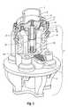
- FIG. 2illustrates a cutaway view of some embodiments of the present invention illustrating various internal components that may comprise some embodiments of the invention
- FIG. 3is an additional illustration of a cutaway view of some embodiments of the present invention illustrating various internal components of some embodiments of the invention
- FIG. 4is an additional illustration of a cutaway view of some embodiments of the present invention illustrating various components of which the present invention may be comprised.
- FIG. 5illustrates a nozzle which may be utilized in some embodiments of the present invention
- FIG. 6illustrates an embodiment of a rotational ratcheting mechanism which may be utilized in some embodiments of the present invention.
- FIGS. 6 a and 6 billustrate an embodiment of a rotational ratcheting mechanism which may be utilized in some embodiments of the present invention
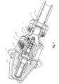
- FIG. 7illustrates an embodiment of a cutting tool particularly depicting the use of a nitrogen spring
- FIG. 8illustrates an embodiment of the shifting apparatus, particularly depicting the addition of a washer with slits utilized to control the flow of fluids which contact the top of the helical spline.
- the present inventionrelates to a system for removing coke from coke drums. This removal process is often referred to as “decoking.” More particularly, the present invention relates to a system that allows an operator to remotely switch a cutting tool between the boring and cutting modes.
- coke drumsIn the typical delayed coking process, high boiling petroleum residues are fed into one or more coke drums where they are thermally cracked into light products and a solid residue-petroleum coke.
- the coke drums containing the cokeare typically large cylindrical vessels.
- the decoking processis a final process in the petroleum refining process and, once a process known as “de-heading” has taken place, the coke is removed from these drums by coke-cutting means.
- fresh feed and recycled feedare combined and fed through a line from the bottom of the fractionator.
- the combined feedis pumped through a coke heater and heated to a temperature between about 800° F. to 1000° F.
- the combined feedis partially vaporized and alternatively charged into a pair of coker drums. Hot vapor expelled from the top of the coke drum are recycled to the bottom of the fractionator by a line.
- the unvaporized portion of the coke heater effluentsettles out (“cokes”) in an active coke drum, where the combined effect of temperature and retention time result in coke until the active vessel is full. Once the active vessel is full the heated heavy hydrocarbon feed is redirected to an empty coker vessel where the above described process is repeated.
- Cokeis then removed from the full vessel by first quenching the hot coke with steam and water, then opening a closure unit sealed to the vessel top, hydraulically drilling the coke from the top portion of the vessel, directing the drilled coke from the vessel through an open coker bottom unit through an attached coke chute to a coke receiving area. Opening the closure unit is safely accomplished by a remotely located control unit.
- Decokingis accomplished at most plants using a hydraulic system consisting of a drill stem and drill bit that direct high pressure water jets into the coke bed.
- a rotating combination drill bitreferred to as the cutting tool, is typically about twenty two inches in diameter with several nozzles, and is mounted on the lower end of a long hollow drill stem about seven inches in diameter.
- the drill bitis lowered into the vessel, on the drill stem, through a flanged opening at the top of the vessel.
- a “bore hole”is drilled through the coke using the nozzles, which eject high pressure water at an angle approximately sixty six degrees down from horizontal. This creates a pilot bore hole, about two to three feet in diameter, for the coke to fall through.
- the drill bitis then switched to at least two horizontal nozzles in preparation for cutting the “cut” hole, which extends to the full drum diameter.
- the nozzlesshoot jets of water horizontally outwards, rotating slowly with the drill rod, and those jets cut the coke into pieces, which fall out the open bottom of the vessel, into a chute that directs the coke to a receiving area.
- the drill rodis then withdrawn out the flanged opening at the top of the vessel. Finally, the top and bottom of the vessel are closed by replacing the head units, flanges or other closure devices employed on the vessel unit. The vessel is then clean and ready for the next filling cycle with the heavy hydrocarbon feed.
- the drill stemIn some coke-cutting system, after the boring hole is made, the drill stem must be removed from the coke drum and reset to the cutting mode. This takes time, is inconvenient and potentially hazardous. In other systems the modes are automatically switched. Automatic switching within the coke drum oftentimes results in drill stem clogging, which still requires the drill stem to be removed for cleaning prior to completing the coke-cutting process. Often, in automatic switching systems, it is difficult to determine whether or not the drill stem is in cutting or boring mode, because the entire change takes place within the drum. Mistakes in identifying whether the high pressure water is cutting or boring leads to serious accidents
- the present inventiondescribes a method and system for coke-cutting in a coke drum following the manufacturing of coke therein.
- the present inventionis especially adapted to be used in the de-coking process, the following discussion relates specifically to this manufacturing area. It is foreseeable, however, that the present invention may be adapted to be an integral part of other manufacturing processes producing various elements other than coke, and such processes should thus be considered within the scope of this application.
- the present inventionprovides a system for coke-cutting wherein the drill stem 2 does not need to be removed to change from boring to cutting mode, but rather, modes can be changed remotely.
- the present inventionprovides for a method for coke-cutting wherein the drill stem does not need to be removed to change between the boring and cutting modes.
- the present inventionprovides systems and methods for coke-cutting can be used with current coke-cutting techniques.
- FIG. 1illustrates a drill stem coupled to a cutting tool 1 by an attachment means 3 .
- the drill stem and cutting tool depicted in FIG. 1are utilized in some embodiments of the present invention to remove coke from a coke drum.
- FIG. 1further illustrates cutting nozzles 4 and boring nozzles 6 .
- FIG. 1further depicts a view of the exterior of the boring passage 48 which is a passage through which fluids flows between the drill stem and the boring nozzles in some embodiments of the invention.
- some passage ways which allow fluid to flow from the drill stem to the cutting nozzlesare present inside the cutting tool.
- FIG. 1is an embodiment of means for cutting coke from the inside of a coke drum comprising a drill stem coupled to a cutting tool 1 by an attachment means 3 .
- the drill stem and cutting tool depicted in FIG. 1are utilized in some embodiments of the present invention to remove coke from a coke drum.
- FIG. 1further illustrates cutting means comprising cutting nozzles 4 and boring nozzles 6 .
- FIG. 2illustrates a cutaway view of a cutting tool of some embodiments of the present invention.
- high pressure fluidis moved through a drill stem to cutting tool 1 and allowed to eject from either the boring nozzle 6 or cutting nozzle 4 .
- the systems and methods of the present inventionallow for automatically switching the flow of fluid between the boring and cutting nozzles, such that an operator may remotely switch the flow of fluid being ejected from the cutting tool to eject either from the boring nozzles 6 or the cutting nozzles 4 alternatively as the decoking process dictates.
- an operator utilizing systems and methods of the present inventionmay allow fluid to flow through the drill stem into the cutting tool 1 and out the boring nozzle 6 to produce a bore hole.
- the systems and methods of the present inventionwould allow an operator located at a remote position to stop the flow of fluid being ejected from the boring nozzle 6 and begin ejecting fluid from the cutting nozzles 4 .
- FIG. 2illustrates several of the elements of the systems of some embodiments of the present invention.
- FIG. 2depicts a drill stem coupled by an attachment means 3 to a cutting tool 1 .
- the cutting tool as depicted in FIG. 2is comprised of several elements.
- the cutting tool depicted in FIG. 2is comprised of nozzles for cutting 4 and nozzles for boring 6 .
- the internal chambers of the cutting toolcomprise channels through which fluid may flow from the drill stem into the cutting tool and into either the boring 6 or cutting 4 nozzles.
- a flow diversion apparatus 8is utilized to selectively allow the movement of fluid into the cutting nozzles 4 or into the boring 6 nozzles.
- the flow diversion apparatus 8blocks water from flowing into passage ways which lead to the cutting nozzles 4 or the boring nozzles 4 such that fluid flowing through the cutting stem into the cutting tool 1 is allowed to flow only into the boring nozzles 6 or only into the cutting nozzles 4 .
- the flow diversion of the apparatus 8 of the present inventionis comprised of a main body 10 of the flow diversion apparatus 8 and flow diversion caps 14 wherein the main body 10 of the flow diversion apparatus 8 is coupled to the flow diversion caps 14 , such that the rotation of the main body 10 of the flow diversion apparatus 8 shifts the position of the flow diversion caps 14 in a rotational axes.
- the flow diversion caps 14 coupled to the main body 10 of the flow diversion of the apparatus 8are biased against the interior elements of the cutting tool by a force applicator 12 contained within the main body 10 of the flow diversion apparatus 8 , such that the flow diversion caps 14 are biased against the interior elements of the cutting tool 1 .
- the flow diversion caps 14are comprised of a beveled edge 15 .
- the beveled edge 15acts to seal the passage ways over which the flow diversion cap 14 is present.
- high pressure fluids flowing through the drill stem 2 into the cutting tool 1push against the top edge of the beveled edge 15 forcing the beveled edge 15 of the flow diversion cap 14 into contact with the internal elements of the cutting tool 1 such that fluid is unable to pass into a passage over which the flow diversion cap 14 is present.
- FIG. 2illustrates an embodiment of a means for diverting the flow of fluid exclusively into a boring means or exclusively into a cutting means.
- the means for diverting the flow of fluidin some embodiments comprises a main body 10 of a flow diversion apparatus 8 and flow diversion caps 14 wherein the main body 10 of the flow diversion apparatus 8 is coupled to the flow diversion caps 14 , such that rotation of the main body 10 of the flow diversion apparatus 8 shifts the position of the flow diversion caps 14 in a rotational axes.
- the flow diversion caps 14 coupled to the main body 10 of the flow diversion of the apparatus 8are bias against the interior elements of the cutting tool by a force applicator 12 contained within the main body 10 of the flow diversion apparatus 8 , such that the flow diversion caps 14 are bias against the interior elements of the cutting tool 1 .
- the flow diversion caps 14are comprised of a beveled edge 15 .
- the beveled edge 15acts to seal the passage ways over which the flow diversion cap 14 is present.
- high pressure fluids flowing through the drill stem 2 into the cutting tool 1push against the top edge of the beveled edge 15 forcing the beveled edge 15 of the flow diversion cap 14 into contact with the internal elements of the cutting tool 1 such that fluid is unable to pass into a passage over which the flow diversion cap 14 is present.
- the main body 10 of the flow diversion apparatus 8is coupled to a shifting apparatus 8 .
- the shifting apparatus 18rotates the flow diversion apparatus in 90 degree increments such that the flow diversion apparatus 8 is either blocking the flow of fluids into passage ways 48 which allow fluid to eject from the boring nozzles or is blocking passages 46 which allow fluid to flow into the cutting nozzles 4 .
- the shifting apparatus 18is comprised of at least one spring 20 and preferably two springs 20 , 22 .
- the preferred method for aligning the springs relative to the shifting apparatusis to have an outside spring 20 and an inside spring 22 oriented such that the rotation of the outside spring 20 is in the opposite direction of the rotation of the inside spring 22 such that the tortional influence of the spring system 20 , 22 on the bottom of the shifting apparatus 18 is minimized.
- the springs 20 , 22 of the shifting apparatus 18contact the bottom of a helical spline 24 by a thrust bearing 26 which acts to decrease the rotational force exerted on the bottom of the helical spline 24 .
- the springs 20 , 22are biased against the interior element of the cutting tool 1 and against the bottom of the helical spline 24 . In the absence of any downward force, the springs 20 , 22 force the helical spline 24 vertically upwards from the bottom of the cutting tool 1 .
- Some embodiments of the present inventionfurther comprise of a rotational ratcheting mechanism 28 .
- two rotational ratcheting mechanism 28 , 30are utilized in opposite directions, one allowing clockwise rotation and the other allowing counter clockwise rotation.
- the first rotational ratchet 28is functionally connected to the helical spline 24 .
- the second rotational ratchet 30is functionally connected to a vertically splined post 32 .
- the double ratcheting mechanism of some embodiments of the present inventionallow the shifting apparatus 18 to rotate the flow diversion apparatus 8 as depicted in FIG.
- the first rotational ratchet 28is locked as the helical spline 24 is moved upward, such that the helical spline 24 rotates in a counterclockwise direction as the helical spline 24 moves upward.
- the vertical splines of the vertically splined post 32operably interact with internal vertical splines of the helical spline 24 turning the vertically splined post in a counterclockwise direction.
- the flow diversion apparatus 8is likewise rotated in a counterclockwise direction, and in preferred embodiments the flow diversion apparatus turns exactly 90 degrees such that the flow diversion caps 14 , operably connected to the main body 10 of the flow diversion apparatus 8 shift from allowing fluid to flow into the boring nozzles, effectively covering the passage 46 of fluid into the cutting nozzles 4 , into a position where fluid is allowed to flow into the cutting nozzles 4 and not into the boring nozzles 6 .
- fluidwhen fluid is then reintroduced or the pressure of fluid is increased into the cutting tool 1 through the drill stem 2 , fluid flows through the drill stem 2 into the cutting tool 1 and through small channels in the vertically splined post 32 such that the reintroduction of high pressure fluid into the cutting tool 1 moves through the small channels and applies force to the top of the helical spline 36 .
- the helical spline 24is forced in a downward direction.
- a second rotationally ratcheting mechanism 30 operably connected to the vertically splined nut 32operates to lock the vertically splined nut 32 from rotating while the helical spline 24 moves in a downward direction.
- the first rotational ratchet 28is locked when the shifting apparatus 18 is moving upward under the absence of the water pressure forcing the helical spline 24 to rotate while the second rotational ratchet 30 is allowed to freewheel in a counterclockwise direction allowing the vertically splined post 32 of the shifting apparatus 18 to rotate is a counterclockwise direction.
- water pressureis reintroduced into the system and the helical spline 24 moves in a downward direction the first rotational ratchet 28 is allowed to freewheel while the second rotational ratchet 30 is locked, preventing the rotation of the flow diversion apparatus during the downward movement of the helical spline 24 .
- Some embodiments of the present inventionfurther comprise a rotational ratchet means 28 .
- two rotational ratcheting means 28 , 30are utilized in opposite directions, one allowing clockwise rotation and the other allowing counter clockwise rotation.
- the first rotational ratchet means 28is functionally connected to the helical spline 24 .
- the second rotational ratchet means 30is functionally connected to a vertically splined post 32 .
- the double ratcheting mechanism of some embodiments of the present inventionallow the shifting apparatus 18 to rotate the flow diversion apparatus 8 as depicted in FIG. 2 in a counterclockwise direction as the elements of the shifting apparatus 18 move in an upward direction, but allow the elements of the shifting apparatus 18 to move vertically downwards without rotating the flow diversion apparatus 8 in a clockwise direction.
- FIGS. 2 and 3additionally illustrate an embodiment of the means for remotely shifting a diverting means between cutting and boring modes.
- the means for remotely shiftingcomprises at least one spring 20 and preferably two springs 20 , 22 .
- the preferred method for aligning the springs relative to the shifting apparatusis to have an outside spring 20 and an inside spring 22 oriented such that the rotation of the outside spring 20 is in the opposite direction of the rotation of the inside spring 22 such that the tortional influence of the spring system 20 , 22 on the bottom of the shifting apparatus 18 is minimized.
- the springs 20 , 22 of the shifting apparatus 18contact the bottom of a helical spline 24 by a thrust bearing 26 which acts to decrease the rotational force exerted on the bottom of the helical spline 24 .
- the springs 20 , 22are biased against the interior element of the cutting tool 1 and against the bottom of the helical spline 24 . In the absence of any downward force, the springs 20 , 22 force the helical spline 24 vertically upwards from the bottom of the cutting tool 1 .
- Some embodiments of the means for remotely shifting a diverting means between cutting and boring modesfurther comprise a rotational ratcheting mechanism 28 .
- the first rotational ratchet 28is functionally connected to the helical spline 24 .
- the second rotational ratchet 30is functionally connected to a vertically splined post 32 .
- the double ratcheting mechanism of some embodiments of the means for remotely shifting a diverting means between cutting and boring modesallow the shifting apparatus 18 to rotate the flow diversion means 8 as depicted in FIG. 2 in a counterclockwise direction as the elements of the shifting apparatus 18 move in an upward direction, but allow the elements of the shifting means 18 to move vertically downwards without rotating the flow diversion means 8 in a clockwise direction.
- the first rotational ratchet 28is locked as the helical spline 24 is moved in an upward direction such that the helical spline 24 rotates in a counterclockwise direction as the helical spline 24 moves in an upward direction.
- the vertical splines of the vertically splined post 32operably interact with internal vertical splines of the helical spline 24 turning the vertically splined post in a counterclockwise direction.
- the flow diversion means 8is likewise rotated in a counterclockwise direction, and in preferred embodiments the flow diversion apparatus turns exactly 90 degrees such that the flow diversion caps 14 , operably connected to the main body 10 of the flow diversion apparatus 8 shift from allowing fluid to flow into the boring nozzles, effectively covering the passage 46 of fluid into the cutting nozzles 4 , into a position where fluid is allowed to flow into the cutting nozzles 4 and not into the boring nozzles 6 .
- the means for remotely shifting a diverting means between cutting and boring modeswhen fluid is then reintroduced or the pressure of fluid is increased into the cutting tool 1 through the drill stem 2 , fluid flows through the drill stem 2 into the cutting tool 1 and through small channels in the vertically splined post 32 such that the reintroduction of high pressure fluid into the cutting tool 1 moves through the small channels and applies force to the top of the helical spline 36 .
- the helical spline 24is forced in a downward direction.
- a second rotationally ratcheting means 30 operably connected to the vertically splined nut 32operates to lock the vertically splined nut 32 from rotating while the helical spline 24 moves in a downward direction.
- the first rotational ratchet means 28is locked when the shifting means 18 is moving upward under the absence of the water pressure forcing the helical spline 24 to rotate while the second rotational ratchet 30 is allowed to freewheel in a counterclockwise direction allowing the vertically splined post 32 of the shifting means 18 to rotate is a counterclockwise direction.
- FIG. 3depicts an embodiment of a cutting tool 1 .
- FIG. 3adds particularity to the operable relations that exist in some embodiments between the vertically splined post 32 and the main body of the fluid diversion apparatus 8 .
- the main body 10 of the fluid diversion apparatus 8may be operably connected to the vertically splined post 32 by a set of vertical splines which translate the rotation of the vertically splined post 32 into the rotation of the main body 10 of the fluid diversion apparatus 8 .
- FIG. 3further illustrates an embodiment of the shifting apparatus collar 38 .
- the shifting apparatus collar 38surrounds the vertically splined post 32 and holds the second rotational ratchet 30 against the vertically splined post 32 .
- the shifting collar 38may be comprised of small channels 34 , which allow fluids in the cutting head 1 , to contact the top surface of the helical spline 36 .
- the shifting apparatus 38also acts to support the bottom of the main body of the flow diversion apparatus 10 maintaining specific vertical tolerances within the body of the cutting tool 1 .
- FIG. 3further illustrates a spring actuated system 12 utilized in some embodiments to apply a downward force to the flow diversion caps 14 .
- the force applicator 12in some embodiments of the present invention is comprised of a spring biased against the main body flow diversion of the apparatus 10 and the top of the flow diversion caps 14 such that the spring supplies a continual downward force on the flow diversion caps 14 . Because the flow diversion caps, in some embodiments of the present invention, are pushed downward by the force applicator 12 consistently even through the rotationally shifting movements the bottom of the beveled edge 15 of the flow diversion caps 14 is polished by its radial movement across the main body of the cutting tool 1 . This polishing effect increases the sealing capacity of the flow diversion caps over time. Thus, in some embodiments, the capacity for the switching tool to function does not decrease with time.
- FIG. 4illustrates the use of an indexing key 42 which is one or more posts which extends from the body of the helical spline 24 and which operably interact with notches 44 either in the shifting apparatus 18 or in the main body of the cutting head itself 1 .
- the indexing key 42 at the bottom of the shifting apparatus 18ensures that the shifting apparatus 18 rotates to a precise rotational position such that the flow diversion caps 14 of the embodiments of the present invention align appropriately with the passageways which correspond to boring and cutting.
- the indexing key 42 /notch 44 system for insuring appropriate rotational movement of the shifting apparatus 18may or may not be utilized on any of the embodiments of the present invention.
- FIG. 5illustrates a nozzle which may be utilized in the present invention.
- the nozzlemay be utilized as a boring nozzle 6 or a cutting nozzle 4 .
- the depicted nozzleis coupled to the cutting tool 1 and allows fluid to flow from a cutting passage 46 or a boring passage 48 such that fluid introduced into the cutting tool 1 , through the drill stem, 2 may be allowed to flow from the internal passages of the cutting tool 1 through the nozzle 4 , 6 and utilize to cut coke from the coke drum.
- the interior of the nozzleis characterized by a series of smaller straw like tubes.
- the length of the straw-like tubesare modified to maximize the laminar flow of the fluids exiting the nozzle 4 , 6 .
- the laminar flow of fluid exiting the boring 6 or cutting nozzles 4is increased thereby increasing the efficiency of the boring or cutting steps of the coke in the drum.
- FIGS. 6 a and 6 bdepict preferred embodiments of the first and second rotational ratchet 28 , of the present invention.
- the rotational ratchet(s) of the present inventionmay be comprised of an outer race 50 , a locking roller 52 , and guide disk 54 , an inter race 56 and a spring loaded plunger 58 .
- FIG. 7depicts an embodiment of the cutting tool of the present invention.
- FIG. 7adds specificity to an additional embodiment of a spring system which may be utilized to move the shifting apparatus 18 vertically.
- FIG. 7depicts a nitrogen spring 23 which may be utilized in preferred embodiments of the present invention.
- the nitrogen springis comprised of a high pressure inert gas contained within a chamber which is used to apply an upward force on the bottom of the helical spline 24 .
- the pressure within the nitrogen springis carefully calculated so that the upward and downward movement of the helical spline 24 will occur at designated and predetermined pressures.
- the nitrogen spring 23provides additional benefits of more consistent pressure being exerted on the bottom of the shifting apparatus. Accordingly, the nitrogen spring 23 as depicted in FIG. 7 may be utilized to allow smoother shifting between the boring and cutting mode.
- FIG. 8depicts an embodiment of the flow diversion apparatus and shifting apparatus of the present invention.
- FIG. 8adds specificity to an embodiment of the invention wherein a washer with slits 50 may be utilized to control the flow of fluids into the small channels 34 .
- the washer with slits 50controls the rate at which pressure is exerted on the top of the helical spline 36 . Accordingly, in some embodiments the use of a washer with slit allows smoother, more controlled shifting between the boring and cutting modes in the present invention.
- Some embodiments of the present inventioncontemplate utilizing and controlling the number and size of slits in the washer 50 such that in some cutting tools more water may be allowed to flow and act upon the top of the helical spline 36 and in some embodiments less fluid would be allowed to act upon the helical spline 36 .
- FIGS. 7 and 8additionally illustrate that in some embodiments fluid is prevented from coming in contact with any of the moving or functional parts of the present invention. That is, the internal works of the present invention (e.g., vertically splined post) are isolated from water and/or debris which may cause the internal components of prior art complications to malfunction over time. Because the internal elements of the present invention are isolated from water and debris, their functionality and efficiencies are not diminished as a product of use or time.
- the internal works of the present inventione.g., vertically splined post
- the internal elements of the present inventionare isolated from water and debris, their functionality and efficiencies are not diminished as a product of use or time.
- the various elements of the inventionare constructed from durable materials such that the various elements of the invention will not require replacement for substantial period of time.
- the helical spline 24 of the present inventionmay be constructed from durable materials and may be capable of efficiently and reliably switching between the boring and cutting modes for substantial periods of time without repair, malfunction or replacement.
- other elements of the cutting tool of the present inventionmay be constructed from durable materials known in the art.
- the present inventionprovides for a method for switching automatically between the cutting and boring modes in a delayed coker unit operation.
- the methodactuating remotely the cutting and/or boring modes during the de-coking by an operator without having to raise the drill stem and cutting unit from the coke drum to be manually altered or inspected.
- the method as describedis comprised of switching between boring and cutting without raising the cutting tool from the coke drum to be decoked.
- the method of the present inventioncomprises an operator allowing high pressure fluid to flow down the drill stem of a delayed coker unit into the cutting tool 1 wherein the high pressure fluid moves through the drill stem 2 into the cutting tool 1 and into boring passages 48 located on the interior of the cutting tool 1 such that the high pressure fluid is allowed to eject from the boring nozzle 6 of the cutting tool 1 .
- the high pressure fluidswhen high pressure fluids is allowed into the cutting tool, a portion of the high pressure fluids moves into the cutting tool, through small channels 34 in the shifting apparatus collar 38 , applying a downward force on the top of the helical spline 36 .
- an operatormay then cut or decrease the flow of high pressure fluid into the drill stem. Accordingly, the flow of the high pressure fluid into the cutting tool 1 is substantially decreased or terminated.
- the flow of fluid through the small channels 34 in the shifting apparatus color 38is decreased and the downward pressure applied to the top of the rotational splined nut 36 is decreased to such an extent that the upward force exhorted by the spring system 20 , 22 forces the helical spline 24 in an upward direction.
- the helical splineAs the helical spline moves in an upward direction, it rotates the main body 10 of the flow diversion apparatus 8 such that the flow diversion apparatus 8 blocks the passages which allow fluid to enter into the boring nozzles 48 and opens the cutting passage 46 allowing fluid to enter into the cutting nozzles 4 .
- the operatormay increase the flow of fluid into the cutting tool allowing high pressure fluid to be ejected from the cutting nozzles 4 as it flows through the drill stem 2 into the cutting tool 1 and through the cutting passages 46 to the cutting nozzles 4 .
- high pressure fluidsare reintroduced into the cutting head, a portion of the high pressure fluids flow through the shifting apparatus collar 38 through small channels 34 and applies a downward pressure on the top of the helical spline 36 , such that the helical spline 24 moves downward and remains in a fully depressed position until the high pressure fluid is cut off.
- the drill stem 2 and cutting tool 1may be lowered into a coke drum and high pressure fluids may be ejected from a set of boring nozzles 6 in a cutting tool 1 .
- the operatordecreases or cuts off the flow of fluid to the cutting tool, allowing the shifting apparatus of the present invention to shift from boring to cutting and then reintroduce high pressure fluids into the drill stem, and cutting tool allowing high pressure fluids to be ejected through the cutting nozzles of the present invention.
Landscapes
- Chemical & Material Sciences (AREA)
- Engineering & Computer Science (AREA)
- Materials Engineering (AREA)
- Oil, Petroleum & Natural Gas (AREA)
- Organic Chemistry (AREA)
- Coke Industry (AREA)
Abstract
Description
Claims (28)
Priority Applications (1)
| Application Number | Priority Date | Filing Date | Title |
|---|---|---|---|
| US12/348,768US8679298B2 (en) | 2004-04-22 | 2009-01-05 | Remotely controlled decoking tool used in coke cutting operations |
Applications Claiming Priority (4)
| Application Number | Priority Date | Filing Date | Title |
|---|---|---|---|
| US56444904P | 2004-04-22 | 2004-04-22 | |
| US10/997,234US7117959B2 (en) | 2004-04-22 | 2004-11-24 | Systems and methods for remotely determining and changing cutting modes during decoking |
| US11/245,384US7473337B2 (en) | 2004-04-22 | 2005-10-06 | Remotely controlled decoking tool used in coke cutting operations |
| US12/348,768US8679298B2 (en) | 2004-04-22 | 2009-01-05 | Remotely controlled decoking tool used in coke cutting operations |
Related Parent Applications (1)
| Application Number | Title | Priority Date | Filing Date |
|---|---|---|---|
| US11/245,384Continuation-In-PartUS7473337B2 (en) | 2004-04-22 | 2005-10-06 | Remotely controlled decoking tool used in coke cutting operations |
Publications (2)
| Publication Number | Publication Date |
|---|---|
| US20090200152A1 US20090200152A1 (en) | 2009-08-13 |
| US8679298B2true US8679298B2 (en) | 2014-03-25 |
Family
ID=40937963
Family Applications (1)
| Application Number | Title | Priority Date | Filing Date |
|---|---|---|---|
| US12/348,768Active2028-05-16US8679298B2 (en) | 2004-04-22 | 2009-01-05 | Remotely controlled decoking tool used in coke cutting operations |
Country Status (1)
| Country | Link |
|---|---|
| US (1) | US8679298B2 (en) |
Cited By (1)
| Publication number | Priority date | Publication date | Assignee | Title |
|---|---|---|---|---|
| US20120138324A1 (en)* | 2010-09-23 | 2012-06-07 | Ruhrpumpen Gmbh | Tool for crushing coke |
Citations (111)
| Publication number | Priority date | Publication date | Assignee | Title |
|---|---|---|---|---|
| US176321A (en) | 1876-04-18 | Improvement in stop-cocks | ||
| US1656355A (en) | 1921-04-21 | 1928-01-17 | Koppers Co Inc | Coke-oven valve construction |
| US1991621A (en) | 1932-03-02 | 1935-02-19 | William Powell Company | High pressure globe valve |
| US2064567A (en) | 1936-02-14 | 1936-12-15 | Fred E Riley | Valve |
| US2245554A (en) | 1938-02-21 | 1941-06-17 | Shell Dev | Hydraulic disruption of solids |
| US2317566A (en) | 1941-07-24 | 1943-04-27 | Socony Vacuum Oil Co Inc | Apparatus for coking oils |
| US2403608A (en) | 1940-12-19 | 1946-07-09 | Socony Vacuum Oil Co Inc | Method of coking oils |
| US2562285A (en) | 1947-04-16 | 1951-07-31 | Dikkers & Co N V G | Gate valve |
| US2717865A (en) | 1951-05-17 | 1955-09-13 | Exxon Research Engineering Co | Coking of heavy hydrocarbonaceous residues |
| US2734715A (en) | 1956-02-14 | Spherical valve | ||
| US2761160A (en) | 1952-08-16 | 1956-09-04 | Standard Oil Co | Coke removal drilling rig |
| US2950897A (en) | 1956-04-19 | 1960-08-30 | Walworth Co | Valve construction |
| US3215399A (en) | 1962-05-28 | 1965-11-02 | Crane Co | Double disc construction for gate valves |
| US3367625A (en) | 1965-06-22 | 1968-02-06 | Fortune Ronald | Slide gate valves |
| US3379623A (en) | 1964-04-16 | 1968-04-23 | James M. Forsyth | Bottom quick-opening door for coking tower or chamber |
| US3617480A (en) | 1969-05-29 | 1971-11-02 | Great Lakes Carbon Corp | Two stages of coking to make a high quality coke |
| US3646947A (en) | 1969-04-04 | 1972-03-07 | Brown & Root | Jacket pile cleanout apparatus |
| US3716310A (en) | 1970-03-09 | 1973-02-13 | Gun Web Ltd | Direct drive ball piston compressor |
| US3837356A (en) | 1973-04-20 | 1974-09-24 | Allis Chalmers | High temperature valve |
| US3852047A (en) | 1969-06-09 | 1974-12-03 | Texaco Inc | Manufacture of petroleum coke |
| SU558524A1 (en) | 1973-11-19 | 1977-05-15 | Предприятие П/Я В-2223 | Hydraulic decoking device |
| US4125438A (en) | 1977-09-19 | 1978-11-14 | United States Steel Corporation | Guiding means for coke oven doors |
| US4174728A (en) | 1977-11-14 | 1979-11-20 | The United States Of America As Represented By The United States Department Of Energy | Sliding-gate valve |
| US4253487A (en) | 1978-11-13 | 1981-03-03 | Exxon Research & Engineering Co. | Multi-position dual disc slide valve |
| US4275842A (en) | 1979-11-21 | 1981-06-30 | Dresser Industries, Inc. | Decoking nozzle assembly |
| US4335733A (en) | 1979-09-17 | 1982-06-22 | Richards John A | Valve for use in handling abrasive materials and method of wear prevention |
| SU959413A1 (en) | 1980-12-31 | 1982-09-15 | Предприятие П/Я В-2223 | Device for the hydraulic extraction of coke |
| US4410398A (en) | 1982-02-22 | 1983-10-18 | Shell Oil Company | Method and apparatus for monitoring the cutting of coke in a petroleum process |
| USRE31439E (en) | 1974-10-11 | 1983-11-15 | Exxon Research And Engineering Co. | Process for operating a magnetically stabilized fluidized bed |
| US4492103A (en) | 1983-02-11 | 1985-01-08 | Bs&B Safety Systems, Inc. | Apparatus for manufacturing rupture disks |
| US4531539A (en) | 1981-11-23 | 1985-07-30 | General Signal Corporation | Control valve for flow of solids |
| US4611613A (en) | 1985-01-29 | 1986-09-16 | Standard Oil Company (Indiana) | Decoking apparatus |
| US4626320A (en) | 1984-02-22 | 1986-12-02 | Conoco Inc. | Method for automated de-coking |
| US4666585A (en) | 1985-08-12 | 1987-05-19 | Atlantic Richfield Company | Disposal of petroleum sludge |
| US4726109A (en) | 1986-10-09 | 1988-02-23 | Foster Wheeler Usa Corporation | Unheading device and method for coking drums |
| US4738399A (en) | 1985-11-25 | 1988-04-19 | Dresser Industries, Inc. | Decoking tool |
| US4771805A (en) | 1982-12-30 | 1988-09-20 | Vetco Gray Inc. | Gate valve |
| US4797197A (en) | 1985-02-07 | 1989-01-10 | Mallari Renato M | Delayed coking process |
| US4824016A (en) | 1987-12-10 | 1989-04-25 | Exxon Research And Engineering Company | Acoustic monitoring of two phase feed nozzles |
| US4877488A (en) | 1986-10-30 | 1989-10-31 | Exxon Research And Engineering Company | Passive acoustic power spectra to monitor and control processing |
| US4923021A (en) | 1988-12-30 | 1990-05-08 | Conoco Inc. | Combination bit for coking oven |
| US4929339A (en) | 1984-03-12 | 1990-05-29 | Foster Wheeler U.S.A. Corporation | Method for extended conditioning of delayed coke |
| US4960358A (en) | 1988-01-26 | 1990-10-02 | Foster Wheeler U.S.A. | Bottom-unheading device and method for vertical vessels |
| US4973386A (en) | 1987-07-13 | 1990-11-27 | Exxon Research And Engineering Company | Passive acoustic power spectra to monitor and control processing |
| US4993264A (en) | 1989-03-02 | 1991-02-19 | Exxon Research And Engineering Company | Passive acoustics process to monitor fluidized bed level |
| US5004152A (en) | 1989-10-30 | 1991-04-02 | Exxon Research & Engineering Company | Acoustic monitoring of two phase feed nozzles |
| US5022268A (en) | 1989-05-22 | 1991-06-11 | Exxon Research And Engineering Company | Passive acoustics system to monitor fluidized bed systems |
| US5022266A (en) | 1989-03-02 | 1991-06-11 | Exxon Research And Engineering Company | Passive acoustics process to monitor fluidized bed flow |
| US5024730A (en) | 1990-06-07 | 1991-06-18 | Texaco Inc. | Control system for delayed coker |
| US5035221A (en) | 1989-01-11 | 1991-07-30 | Martin Tiby M | High pressure electronic common-rail fuel injection system for diesel engines |
| US5041207A (en) | 1986-12-04 | 1991-08-20 | Amoco Corporation | Oxygen addition to a coking zone and sludge addition with oxygen addition |
| US5048876A (en) | 1989-11-02 | 1991-09-17 | Fluor Corporation | Closure apparatus for pipes and vessels |
| US5059331A (en) | 1990-03-06 | 1991-10-22 | Amoco Corporation | Solids-liquid separation |
| US5107873A (en) | 1989-08-08 | 1992-04-28 | Halliburton Company | Chamber cleaning apparatus and method |
| US5116022A (en) | 1990-04-06 | 1992-05-26 | Zimmermann & Jansen Gmbh | Stop valve for pipe bridge |
| US5221019A (en) | 1991-11-07 | 1993-06-22 | Hahn & Clay | Remotely operable vessel cover positioner |
| US5228525A (en) | 1990-02-27 | 1993-07-20 | Augers Unlimited, Inc. | Adaptor for earth boring machine |
| US5228825A (en) | 1991-11-01 | 1993-07-20 | The M. W. Kellogg Company | Pressure vessel closure device |
| US5299841A (en) | 1993-02-08 | 1994-04-05 | Adsco Manufacturing Corp. | Safety flow restrictor for expansion joints |
| US5417811A (en) | 1994-06-13 | 1995-05-23 | Foster Wheeler Usa Corporation | Closure device for upper head of coking drums |
| USH1442H (en) | 1992-11-16 | 1995-06-06 | Edgerton David M | Petroleum coking drum with slump preventers |
| RU2043604C1 (en) | 1992-03-10 | 1995-09-10 | Ульяновское высшее военно-техническое училище им.Богдана Хмельницкого | Device to measure level and flow rate of liquid |
| US5464035A (en) | 1994-06-21 | 1995-11-07 | Itt Corporation | Gate-type, side-ported, line blind valve |
| US5581864A (en) | 1995-01-17 | 1996-12-10 | Suncor, Inc. | Coke drum deheading system |
| US5633462A (en) | 1994-07-19 | 1997-05-27 | Apa Systems | Method and apparatus for detecting the condition of the flow of liquid metal in and from a teeming vessel |
| US5652145A (en) | 1995-12-22 | 1997-07-29 | Exxon Research And Engineering Company | Passive acoustics process to monitor feed injection lines of a catalytic cracker (law077) |
| US5785843A (en) | 1994-11-30 | 1998-07-28 | Fluor Daniel, Inc. | Low headroom coke drum deheading device |
| US5800680A (en) | 1996-09-06 | 1998-09-01 | Petroleo Brasileiro S.A. - Petrobras | System and method for rapid opening of coking vessels |
| US5816787A (en) | 1996-04-24 | 1998-10-06 | Brinkerhoff; Robert B. | Motion conversion rotator apparatus and method |
| US5816505A (en)* | 1997-04-17 | 1998-10-06 | Ingersoll-Dresser Pump Company | Fluid jet decoking tool |
| US5876568A (en) | 1996-07-25 | 1999-03-02 | Kindersley; Peter | Safe and semi-automatic removal of heavy drum closures |
| US5907491A (en) | 1996-08-23 | 1999-05-25 | Csi Technology, Inc. | Wireless machine monitoring and communication system |
| US5927684A (en) | 1996-10-23 | 1999-07-27 | Zimmerman & Jansen Gmbh | Slide, particularly pipe bridge slide |
| US5947674A (en) | 1996-07-19 | 1999-09-07 | Foster Wheeler Usa Corp. | Coking vessel unheading device and support structure |
| US5974887A (en) | 1997-09-26 | 1999-11-02 | Exxon Research And Engineering Co. | Method for determining operating status of liquid phase gas-phase interaction columns |
| US6007068A (en) | 1996-11-25 | 1999-12-28 | Us Government As Represented By The Administrator Of Nasa Headquarters | Dynamic face seal arrangement |
| US6039844A (en) | 1998-10-09 | 2000-03-21 | Citgo Petroleum Corporation | Containment system for coke drums |
| JP2000145989A (en) | 1998-11-09 | 2000-05-26 | Ingersoll Dresser Pump Co | Switch valve equipped with cutoff and flowing-out functions |
| US6113745A (en) | 1998-06-18 | 2000-09-05 | Fluor Corporation | Coke drum system with movable floor |
| US6117308A (en) | 1998-07-28 | 2000-09-12 | Ganji; Kazem | Foam reduction in petroleum cokers |
| RU2163359C1 (en) | 1999-08-02 | 2001-02-20 | Кустов Евгений Федорович | Liquid-filled column manometer |
| US6223925B1 (en) | 1999-04-22 | 2001-05-01 | Foster Wheeler Corporation | Stud tensioning device for flange cover |
| US6228225B1 (en) | 1998-08-31 | 2001-05-08 | Bechtel Corporation | Coke drum semi automatic top deheader |
| US6254733B1 (en) | 1999-09-01 | 2001-07-03 | Hahn & Clay | Automatic cover removal system |
| US6264797B1 (en) | 1999-09-01 | 2001-07-24 | Hahn & Clay | Method for improving longevity of equipment for opening large, high temperature containers |
| US6367843B1 (en) | 1997-02-03 | 2002-04-09 | Automated Connectors Holdings, L.B. | Remote operable fastener and method of use |
| US20020134658A1 (en) | 2001-03-12 | 2002-09-26 | Lah Ruben F. | Coke drum bottom de-heading system |
| US20020157897A1 (en) | 2001-03-21 | 2002-10-31 | Marcus Hofmann | Device for noise configuration in a motor vehicle |
| US20020166862A1 (en) | 2001-05-11 | 2002-11-14 | Malsbury Allen S. | Modular pressure vessel unheading and containment system |
| US20020170814A1 (en) | 2001-03-12 | 2002-11-21 | Lah Ruben F. | Coke drum bottom de-heading system |
| US20030047153A1 (en) | 1998-11-19 | 2003-03-13 | Michael Kubel | Hydraulically controllable globe valve |
| US6539805B2 (en) | 1994-07-19 | 2003-04-01 | Vesuvius Crucible Company | Liquid metal flow condition detection |
| US6547250B1 (en) | 2000-08-21 | 2003-04-15 | Westport Research Inc. | Seal assembly with two sealing mechanisms for providing static and dynamic sealing |
| US20030089589A1 (en) | 2001-11-09 | 2003-05-15 | Foster Wheeler Usa Corporation | Coke drum discharge system |
| US20030127314A1 (en) | 2002-01-10 | 2003-07-10 | Bell Robert V. | Safe and automatic method for removal of coke from a coke vessel |
| US20030159737A1 (en) | 2002-02-22 | 2003-08-28 | Dresser, Inc. | High capacity globe valve |
| US20030185718A1 (en) | 2002-03-12 | 2003-10-02 | Foster Wheeler Energy Corporation | Method and apparatus for removing mercury species from hot flue gas |
| US6644567B1 (en)* | 2002-06-28 | 2003-11-11 | Flowserve Management Company | Remotely operated cutting mode shifting apparatus for a combination fluid jet decoking tool |
| US6738697B2 (en) | 1995-06-07 | 2004-05-18 | Automotive Technologies International Inc. | Telematics system for vehicle diagnostics |
| US20040118746A1 (en) | 2002-12-18 | 2004-06-24 | Chevron U.S.A. Inc. | Safe and automatic method for preparation of coke for removal from a coke vessel |
| US20040154913A1 (en) | 2001-03-12 | 2004-08-12 | Lah Ruben F. | Valve system and method for unheading a coke drum |
| US6843889B2 (en) | 2002-09-05 | 2005-01-18 | Curtiss-Wright Flow Control Corporation | Coke drum bottom throttling valve and system |
| US6926807B2 (en) | 2003-06-12 | 2005-08-09 | Chevron U.S.A. Inc. | Insulated transition spool apparatus |
| US6964727B2 (en) | 2001-03-12 | 2005-11-15 | Curtiss-Wright Flow Control Corporation | Coke drum bottom de-heading system |
| US7115190B2 (en) | 2003-02-21 | 2006-10-03 | Curtiss-Wright Flow Control Corporation | Tangential dispenser and system for use within a delayed coking system |
| US7117959B2 (en)* | 2004-04-22 | 2006-10-10 | Curtiss-Wright Flow Control Corporation | Systems and methods for remotely determining and changing cutting modes during decoking |
| US7316762B2 (en) | 2003-04-11 | 2008-01-08 | Curtiss-Wright Flow Control Corporation | Dynamic flange seal and sealing system |
| US7473337B2 (en)* | 2004-04-22 | 2009-01-06 | Curtiss-Wright Flow Control Corporation | Remotely controlled decoking tool used in coke cutting operations |
| US7815775B2 (en)* | 2007-08-27 | 2010-10-19 | Exxonmobil Research & Engineering Company | Optimized coke cutting method for decoking substantially free-flowing coke in delayed cokers |
| US7819343B2 (en)* | 2007-12-31 | 2010-10-26 | Ruhrpumpen Gmbh | Decoking tool |
| US7828959B2 (en)* | 2007-11-19 | 2010-11-09 | Kazem Ganji | Delayed coking process and apparatus |
Family Cites Families (1)
| Publication number | Priority date | Publication date | Assignee | Title |
|---|---|---|---|---|
| US1653655A (en)* | 1927-12-27 | Calculator |
- 2009
- 2009-01-05USUS12/348,768patent/US8679298B2/enactiveActive
Patent Citations (121)
| Publication number | Priority date | Publication date | Assignee | Title |
|---|---|---|---|---|
| US2734715A (en) | 1956-02-14 | Spherical valve | ||
| US176321A (en) | 1876-04-18 | Improvement in stop-cocks | ||
| US1656355A (en) | 1921-04-21 | 1928-01-17 | Koppers Co Inc | Coke-oven valve construction |
| US1991621A (en) | 1932-03-02 | 1935-02-19 | William Powell Company | High pressure globe valve |
| US2064567A (en) | 1936-02-14 | 1936-12-15 | Fred E Riley | Valve |
| US2245554A (en) | 1938-02-21 | 1941-06-17 | Shell Dev | Hydraulic disruption of solids |
| US2403608A (en) | 1940-12-19 | 1946-07-09 | Socony Vacuum Oil Co Inc | Method of coking oils |
| US2317566A (en) | 1941-07-24 | 1943-04-27 | Socony Vacuum Oil Co Inc | Apparatus for coking oils |
| US2562285A (en) | 1947-04-16 | 1951-07-31 | Dikkers & Co N V G | Gate valve |
| US2717865A (en) | 1951-05-17 | 1955-09-13 | Exxon Research Engineering Co | Coking of heavy hydrocarbonaceous residues |
| US2761160A (en) | 1952-08-16 | 1956-09-04 | Standard Oil Co | Coke removal drilling rig |
| US2950897A (en) | 1956-04-19 | 1960-08-30 | Walworth Co | Valve construction |
| US3215399A (en) | 1962-05-28 | 1965-11-02 | Crane Co | Double disc construction for gate valves |
| US3379623A (en) | 1964-04-16 | 1968-04-23 | James M. Forsyth | Bottom quick-opening door for coking tower or chamber |
| US3367625A (en) | 1965-06-22 | 1968-02-06 | Fortune Ronald | Slide gate valves |
| US3646947A (en) | 1969-04-04 | 1972-03-07 | Brown & Root | Jacket pile cleanout apparatus |
| US3617480A (en) | 1969-05-29 | 1971-11-02 | Great Lakes Carbon Corp | Two stages of coking to make a high quality coke |
| US3852047A (en) | 1969-06-09 | 1974-12-03 | Texaco Inc | Manufacture of petroleum coke |
| US3716310A (en) | 1970-03-09 | 1973-02-13 | Gun Web Ltd | Direct drive ball piston compressor |
| US3837356A (en) | 1973-04-20 | 1974-09-24 | Allis Chalmers | High temperature valve |
| SU558524A1 (en) | 1973-11-19 | 1977-05-15 | Предприятие П/Я В-2223 | Hydraulic decoking device |
| USRE31439E (en) | 1974-10-11 | 1983-11-15 | Exxon Research And Engineering Co. | Process for operating a magnetically stabilized fluidized bed |
| US4125438A (en) | 1977-09-19 | 1978-11-14 | United States Steel Corporation | Guiding means for coke oven doors |
| US4174728A (en) | 1977-11-14 | 1979-11-20 | The United States Of America As Represented By The United States Department Of Energy | Sliding-gate valve |
| US4253487A (en) | 1978-11-13 | 1981-03-03 | Exxon Research & Engineering Co. | Multi-position dual disc slide valve |
| US4335733A (en) | 1979-09-17 | 1982-06-22 | Richards John A | Valve for use in handling abrasive materials and method of wear prevention |
| US4275842A (en) | 1979-11-21 | 1981-06-30 | Dresser Industries, Inc. | Decoking nozzle assembly |
| SU959413A1 (en) | 1980-12-31 | 1982-09-15 | Предприятие П/Я В-2223 | Device for the hydraulic extraction of coke |
| US4531539A (en) | 1981-11-23 | 1985-07-30 | General Signal Corporation | Control valve for flow of solids |
| US4410398A (en) | 1982-02-22 | 1983-10-18 | Shell Oil Company | Method and apparatus for monitoring the cutting of coke in a petroleum process |
| US4771805A (en) | 1982-12-30 | 1988-09-20 | Vetco Gray Inc. | Gate valve |
| US4492103A (en) | 1983-02-11 | 1985-01-08 | Bs&B Safety Systems, Inc. | Apparatus for manufacturing rupture disks |
| US4626320A (en) | 1984-02-22 | 1986-12-02 | Conoco Inc. | Method for automated de-coking |
| US4929339A (en) | 1984-03-12 | 1990-05-29 | Foster Wheeler U.S.A. Corporation | Method for extended conditioning of delayed coke |
| US4611613A (en) | 1985-01-29 | 1986-09-16 | Standard Oil Company (Indiana) | Decoking apparatus |
| US4797197A (en) | 1985-02-07 | 1989-01-10 | Mallari Renato M | Delayed coking process |
| US4666585A (en) | 1985-08-12 | 1987-05-19 | Atlantic Richfield Company | Disposal of petroleum sludge |
| US4738399A (en) | 1985-11-25 | 1988-04-19 | Dresser Industries, Inc. | Decoking tool |
| US4726109A (en) | 1986-10-09 | 1988-02-23 | Foster Wheeler Usa Corporation | Unheading device and method for coking drums |
| US4877488A (en) | 1986-10-30 | 1989-10-31 | Exxon Research And Engineering Company | Passive acoustic power spectra to monitor and control processing |
| US5041207A (en) | 1986-12-04 | 1991-08-20 | Amoco Corporation | Oxygen addition to a coking zone and sludge addition with oxygen addition |
| US4973386A (en) | 1987-07-13 | 1990-11-27 | Exxon Research And Engineering Company | Passive acoustic power spectra to monitor and control processing |
| US4824016A (en) | 1987-12-10 | 1989-04-25 | Exxon Research And Engineering Company | Acoustic monitoring of two phase feed nozzles |
| US4960358A (en) | 1988-01-26 | 1990-10-02 | Foster Wheeler U.S.A. | Bottom-unheading device and method for vertical vessels |
| US4923021A (en) | 1988-12-30 | 1990-05-08 | Conoco Inc. | Combination bit for coking oven |
| US5035221A (en) | 1989-01-11 | 1991-07-30 | Martin Tiby M | High pressure electronic common-rail fuel injection system for diesel engines |
| US4993264A (en) | 1989-03-02 | 1991-02-19 | Exxon Research And Engineering Company | Passive acoustics process to monitor fluidized bed level |
| US5022266A (en) | 1989-03-02 | 1991-06-11 | Exxon Research And Engineering Company | Passive acoustics process to monitor fluidized bed flow |
| US5022268A (en) | 1989-05-22 | 1991-06-11 | Exxon Research And Engineering Company | Passive acoustics system to monitor fluidized bed systems |
| US5107873A (en) | 1989-08-08 | 1992-04-28 | Halliburton Company | Chamber cleaning apparatus and method |
| US5004152A (en) | 1989-10-30 | 1991-04-02 | Exxon Research & Engineering Company | Acoustic monitoring of two phase feed nozzles |
| US5048876A (en) | 1989-11-02 | 1991-09-17 | Fluor Corporation | Closure apparatus for pipes and vessels |
| US5228525A (en) | 1990-02-27 | 1993-07-20 | Augers Unlimited, Inc. | Adaptor for earth boring machine |
| US5059331A (en) | 1990-03-06 | 1991-10-22 | Amoco Corporation | Solids-liquid separation |
| US5116022A (en) | 1990-04-06 | 1992-05-26 | Zimmermann & Jansen Gmbh | Stop valve for pipe bridge |
| US5024730A (en) | 1990-06-07 | 1991-06-18 | Texaco Inc. | Control system for delayed coker |
| US5228825A (en) | 1991-11-01 | 1993-07-20 | The M. W. Kellogg Company | Pressure vessel closure device |
| US5221019A (en) | 1991-11-07 | 1993-06-22 | Hahn & Clay | Remotely operable vessel cover positioner |
| RU2043604C1 (en) | 1992-03-10 | 1995-09-10 | Ульяновское высшее военно-техническое училище им.Богдана Хмельницкого | Device to measure level and flow rate of liquid |
| USH1442H (en) | 1992-11-16 | 1995-06-06 | Edgerton David M | Petroleum coking drum with slump preventers |
| US5299841A (en) | 1993-02-08 | 1994-04-05 | Adsco Manufacturing Corp. | Safety flow restrictor for expansion joints |
| US5417811A (en) | 1994-06-13 | 1995-05-23 | Foster Wheeler Usa Corporation | Closure device for upper head of coking drums |
| US5464035A (en) | 1994-06-21 | 1995-11-07 | Itt Corporation | Gate-type, side-ported, line blind valve |
| US6539805B2 (en) | 1994-07-19 | 2003-04-01 | Vesuvius Crucible Company | Liquid metal flow condition detection |
| US5633462A (en) | 1994-07-19 | 1997-05-27 | Apa Systems | Method and apparatus for detecting the condition of the flow of liquid metal in and from a teeming vessel |
| US5785843A (en) | 1994-11-30 | 1998-07-28 | Fluor Daniel, Inc. | Low headroom coke drum deheading device |
| US6264829B1 (en) | 1994-11-30 | 2001-07-24 | Fluor Corporation | Low headroom coke drum deheading device |
| US5581864A (en) | 1995-01-17 | 1996-12-10 | Suncor, Inc. | Coke drum deheading system |
| US6738697B2 (en) | 1995-06-07 | 2004-05-18 | Automotive Technologies International Inc. | Telematics system for vehicle diagnostics |
| US5652145A (en) | 1995-12-22 | 1997-07-29 | Exxon Research And Engineering Company | Passive acoustics process to monitor feed injection lines of a catalytic cracker (law077) |
| US5816787A (en) | 1996-04-24 | 1998-10-06 | Brinkerhoff; Robert B. | Motion conversion rotator apparatus and method |
| US5947674A (en) | 1996-07-19 | 1999-09-07 | Foster Wheeler Usa Corp. | Coking vessel unheading device and support structure |
| US5876568A (en) | 1996-07-25 | 1999-03-02 | Kindersley; Peter | Safe and semi-automatic removal of heavy drum closures |
| US6066237A (en) | 1996-07-25 | 2000-05-23 | Kindersley; Peter | Safe and semi-automatic removal of heavy drum closures |
| US5907491A (en) | 1996-08-23 | 1999-05-25 | Csi Technology, Inc. | Wireless machine monitoring and communication system |
| US5800680A (en) | 1996-09-06 | 1998-09-01 | Petroleo Brasileiro S.A. - Petrobras | System and method for rapid opening of coking vessels |
| US5927684A (en) | 1996-10-23 | 1999-07-27 | Zimmerman & Jansen Gmbh | Slide, particularly pipe bridge slide |
| US6007068A (en) | 1996-11-25 | 1999-12-28 | Us Government As Represented By The Administrator Of Nasa Headquarters | Dynamic face seal arrangement |
| US6367843B1 (en) | 1997-02-03 | 2002-04-09 | Automated Connectors Holdings, L.B. | Remote operable fastener and method of use |
| US5816505A (en)* | 1997-04-17 | 1998-10-06 | Ingersoll-Dresser Pump Company | Fluid jet decoking tool |
| US5974887A (en) | 1997-09-26 | 1999-11-02 | Exxon Research And Engineering Co. | Method for determining operating status of liquid phase gas-phase interaction columns |
| US6113745A (en) | 1998-06-18 | 2000-09-05 | Fluor Corporation | Coke drum system with movable floor |
| US6117308A (en) | 1998-07-28 | 2000-09-12 | Ganji; Kazem | Foam reduction in petroleum cokers |
| US6228225B1 (en) | 1998-08-31 | 2001-05-08 | Bechtel Corporation | Coke drum semi automatic top deheader |
| US6039844A (en) | 1998-10-09 | 2000-03-21 | Citgo Petroleum Corporation | Containment system for coke drums |
| JP2000145989A (en) | 1998-11-09 | 2000-05-26 | Ingersoll Dresser Pump Co | Switch valve equipped with cutoff and flowing-out functions |
| US20030047153A1 (en) | 1998-11-19 | 2003-03-13 | Michael Kubel | Hydraulically controllable globe valve |
| US6223925B1 (en) | 1999-04-22 | 2001-05-01 | Foster Wheeler Corporation | Stud tensioning device for flange cover |
| RU2163359C1 (en) | 1999-08-02 | 2001-02-20 | Кустов Евгений Федорович | Liquid-filled column manometer |
| US6254733B1 (en) | 1999-09-01 | 2001-07-03 | Hahn & Clay | Automatic cover removal system |
| US6264797B1 (en) | 1999-09-01 | 2001-07-24 | Hahn & Clay | Method for improving longevity of equipment for opening large, high temperature containers |
| US6547250B1 (en) | 2000-08-21 | 2003-04-15 | Westport Research Inc. | Seal assembly with two sealing mechanisms for providing static and dynamic sealing |
| US6989081B2 (en) | 2001-03-12 | 2006-01-24 | Curtiss-Wright Flow Control Corporation | Valve system and method for unheading a coke drum |
| US20020170814A1 (en) | 2001-03-12 | 2002-11-21 | Lah Ruben F. | Coke drum bottom de-heading system |
| US20020134658A1 (en) | 2001-03-12 | 2002-09-26 | Lah Ruben F. | Coke drum bottom de-heading system |
| US6964727B2 (en) | 2001-03-12 | 2005-11-15 | Curtiss-Wright Flow Control Corporation | Coke drum bottom de-heading system |
| US6565714B2 (en) | 2001-03-12 | 2003-05-20 | Curtiss-Wright Flow Control Corporation | Coke drum bottom de-heading system |
| US20040154913A1 (en) | 2001-03-12 | 2004-08-12 | Lah Ruben F. | Valve system and method for unheading a coke drum |
| US6660131B2 (en) | 2001-03-12 | 2003-12-09 | Curtiss-Wright Flow Control Corporation | Coke drum bottom de-heading system |
| US20020157897A1 (en) | 2001-03-21 | 2002-10-31 | Marcus Hofmann | Device for noise configuration in a motor vehicle |
| US6644436B2 (en) | 2001-03-21 | 2003-11-11 | Daimlerchrysler Ag | Device for noise configuration in a motor vehicle |
| US20020166862A1 (en) | 2001-05-11 | 2002-11-14 | Malsbury Allen S. | Modular pressure vessel unheading and containment system |
| US6751852B2 (en) | 2001-05-11 | 2004-06-22 | Foster Wheeler Usa Corporation | Modular pressure vessel unheading and containment system |
| US20030089589A1 (en) | 2001-11-09 | 2003-05-15 | Foster Wheeler Usa Corporation | Coke drum discharge system |
| US20030127314A1 (en) | 2002-01-10 | 2003-07-10 | Bell Robert V. | Safe and automatic method for removal of coke from a coke vessel |
| US20030159737A1 (en) | 2002-02-22 | 2003-08-28 | Dresser, Inc. | High capacity globe valve |
| US20030185718A1 (en) | 2002-03-12 | 2003-10-02 | Foster Wheeler Energy Corporation | Method and apparatus for removing mercury species from hot flue gas |
| US6644567B1 (en)* | 2002-06-28 | 2003-11-11 | Flowserve Management Company | Remotely operated cutting mode shifting apparatus for a combination fluid jet decoking tool |
| US6843889B2 (en) | 2002-09-05 | 2005-01-18 | Curtiss-Wright Flow Control Corporation | Coke drum bottom throttling valve and system |
| US7033460B2 (en) | 2002-09-05 | 2006-04-25 | Curtiss-Wright Flow Control Corportaion | Coke drum bottom throttling valve and system |
| US20040118746A1 (en) | 2002-12-18 | 2004-06-24 | Chevron U.S.A. Inc. | Safe and automatic method for preparation of coke for removal from a coke vessel |
| US7037408B2 (en)* | 2002-12-18 | 2006-05-02 | Chevron U.S.A. Inc. | Safe and automatic method for preparation of coke for removal from a coke vessel |
| US7115190B2 (en) | 2003-02-21 | 2006-10-03 | Curtiss-Wright Flow Control Corporation | Tangential dispenser and system for use within a delayed coking system |
| US7316762B2 (en) | 2003-04-11 | 2008-01-08 | Curtiss-Wright Flow Control Corporation | Dynamic flange seal and sealing system |
| US6926807B2 (en) | 2003-06-12 | 2005-08-09 | Chevron U.S.A. Inc. | Insulated transition spool apparatus |
| US7117959B2 (en)* | 2004-04-22 | 2006-10-10 | Curtiss-Wright Flow Control Corporation | Systems and methods for remotely determining and changing cutting modes during decoking |
| US7473337B2 (en)* | 2004-04-22 | 2009-01-06 | Curtiss-Wright Flow Control Corporation | Remotely controlled decoking tool used in coke cutting operations |
| US7820014B2 (en)* | 2004-04-22 | 2010-10-26 | Lah Ruben F | Systems and methods for remotely determining and changing cutting modes during decoking |
| US7815775B2 (en)* | 2007-08-27 | 2010-10-19 | Exxonmobil Research & Engineering Company | Optimized coke cutting method for decoking substantially free-flowing coke in delayed cokers |
| US7828959B2 (en)* | 2007-11-19 | 2010-11-09 | Kazem Ganji | Delayed coking process and apparatus |
| US7819343B2 (en)* | 2007-12-31 | 2010-10-26 | Ruhrpumpen Gmbh | Decoking tool |
Non-Patent Citations (39)
| Title |
|---|
| Claudio Allevato & Richard S. Boswell, "Assessing the Structural Integrity and Remaining Life of Coke Drums with Acoustic Emission Testing, Stain Gaging, and Finite Element Analysis," ETCE 99-Symposium on Plant and Facilities Reliability and Mechanical Integrity, 1999 Engineering Source Technology Conference & Exhibition, Stress Engineering Services, Inc. |
| J. J. Kelley, "Applied Artificial Intelligence for Delayed Coking", Hydrocarbon Processing, Nov. 2000, 144-A-144-J, Gulf Publishing Company, USA. |
| Norm Lieberman, "Coke Drum Foam-Overs Causes & Cures," http://www.coking.com/Foamover.htm, No Date. |
| Paul J. Ellis & Christopher A. Paul, "Tutorial: Delayed Coking Fundamentals," AlChE 1998 Spring National Meeting's International Conference on Refinery Processes Topical Conference Preprints 1998, 1998, Great Lakes Carbon Corporation. |
| U.S. Appl. No. 10/274,280, Examiner's search strategy and results issued Mar. 14, 2004; 2 pages. |
| U.S. Appl. No. 10/274,280, Non-Final Rejection issued Mar. 25, 2004 by the United States Patent and Trademark Office; 10 pages. |
| U.S. Appl. No. 10/274,280, Notice of Allowance and Fees Due, Issue Information and Bibliographic Data Sheet issued Oct. 5, 2004 by the United States Patent and Trademark Office; 8 pages. |
| U.S. Appl. No. 10/411,849, Examiner's search strategy and results issued Aug. 4, 2005; 5 pages. |
| U.S. Appl. No. 10/411,849, Examiner's search strategy and results issued Jul. 18, 2006; 1 page. |
| U.S. Appl. No. 10/411,849, Non-Final Rejection issued Aug. 9, 2005 by the United States Patent and Trademark Office; 8 pages. |
| U.S. Appl. No. 10/411,849, Non-Final Rejection issued Feb. 8, 2006 by the United States Patent and Trademark Office; 7 pages. |
| U.S. Appl. No. 10/411,849, Notice of Allowance and Fees Due, Examiner Interview Summary Record, Issue Information, Index of Claims, Search Information and Bibliographic Data Sheet issued Jul. 24, 2006 by the United States Patent and Trademark Office; 14 pages. |
| U.S. Appl. No. 10/412,628, Non-Final Rejection issued Feb. 16, 2007 by the United States Patent and Trademark Office; 17 pages. |
| U.S. Appl. No. 10/412,628, Notice of Allowance and Fees Due, Bibliographic Data Sheet, Index of Claims, Search Information and Issue Information issued Aug. 24, 2007 by the United States Patent and Trademark Office; 11 pages. |
| U.S. Appl. No. 10/442,673, Examiner's search strategy and results issued Aug. 26, 2004, 2 pages. |
| U.S. Appl. No. 10/442,673, Final Rejection issued Feb. 23, 2005 by the United States Patent and Trademark Office; 6 pages. |
| U.S. Appl. No. 10/442,673, Non-Final Rejection issued Sep. 1, 2004 by the United States Patent and Trademark Office; 10 pages. |
| U.S. Appl. No. 10/442,673, Notice of Allowance and Fees Due, Amendment After Final, Issue Information, Index of Claims and Search Information issued Apr. 20, 2005 by the United States Patent and Trademark Office; 10 pages. |
| U.S. Appl. No. 10/731,874, Examiner's search and strategy results issued Sep. 26, 2005. 1 page. |
| U.S. Appl. No. 10/731,874, Examiner's search strategy and results issued Dec. 5, 2007, 1 page. |
| U.S. Appl. No. 10/731,874, Final Rejection issued Jun. 28, 2005 by the United States Patent and Trademark Office. pp. 1-7. |
| U.S. Appl. No. 10/731,874, Non-Final Rejection issued Apr. 6, 2007 by the United States Patent and Trademark Office; 14 pages. |
| U.S. Appl. No. 10/731,874, Non-Final Rejection issued Dec. 11, 2007 by the United States Patent and Trademark Office; 22 pages. |
| U.S. Appl. No. 10/731,874, Non-Final Rejection issued Feb. 23, 2005 by the United States Patent and Trademark Office. pp. 1-10. |
| U.S. Appl. No. 10/731,874, Non-Final Rejection issued Oct. 13, 2006 by the United States Patent and Trademark Office; 22 pages. |
| U.S. Appl. No. 10/731,874, Notice of Allowance of Fees Due, Issue Information, Index of Claims and Search information issued Sep. 29, 2005 by the United States Patent and Trademark Office; 7 pages. |
| U.S. Appl. No. 10/731,874, Notice of Allowance of Fees Dues, List of References, Issue Information, Search information and index of claims issued Jan. 18, 2006 by the United States Patent and Trademark Office; 10 pages. |
| U.S. Appl. No. 10/731,874, Requirement for Restriction/Election, List of References and index of claims issued Sep. 6, 2007 by the United States Patent and Trademark Office; 20 pages. |
| U.S. Appl. No. 10/873,022, Non-Final Rejection issued Jul. 7, 2005 by the United States Patent and Trademark Office, 12 pages. |
| U.S. Appl. No. 10/873,022, Notice of Allowance and Fees Due, Specification and Issue Information issued Jan. 4, 2006 by the United States Patent and Trademark Office, 9 pages. |
| U.S. Appl. No. 10/997,234, Examiner's search strategy and results issued Aug. 4, 2006; 1 page. |
| U.S. Appl. No. 10/997,234, Examiner's search strategy and results issued Mar. 14, 2006; 3 pages. |
| U.S. Appl. No. 10/997,234, Non-Final Rejection issued Mar. 20, 2006 by the United States Patent and Trademark Office, 13 pages. |
| U.S. Appl. No. 10/997,234, Notice of Allowance and Fees Due, Issue Information, Bibliographic Data Sheet, Index of Claims and Search Information issued Aug. 10, 2006 by the United States Patent and Trademark Office, 8 pages. |
| U.S. Appl. No. 10/997,834, Examiner's search strategy and results issued Jun. 22, 2005; 5 pages. |
| U.S. Appl. No. 10/997,834, Examiner's search strategy and results issued Sep. 26, 2005; 1 page. |
| U.S. Appl. No. 10/997,834, Non-Final Rejection issued Jul. 6, 2005 by the United States Patent and Trademark Office; 44 pages. |
| U.S. Appl. No. 10/997,834, Notice of Allowance and Fees, Issue Information, Index of Claims and search information issued Sep. 29, 2005 by the United States Patent and Trademark Office; 8 pages. |
| Zappe, R.W., Valve Selection Handbook, Fourth Edition, Gulf Publishing Company, Houston, Texas. |
Cited By (2)
| Publication number | Priority date | Publication date | Assignee | Title |
|---|---|---|---|---|
| US20120138324A1 (en)* | 2010-09-23 | 2012-06-07 | Ruhrpumpen Gmbh | Tool for crushing coke |
| US8955618B2 (en)* | 2010-09-23 | 2015-02-17 | Ruhrpumpen Gmbh | Tool for crushing coke |
Also Published As
| Publication number | Publication date |
|---|---|
| US20090200152A1 (en) | 2009-08-13 |
Similar Documents
| Publication | Publication Date | Title |
|---|---|---|
| US8197644B2 (en) | Remotely controlled decoking tool used in coke cutting operations | |
| US7820014B2 (en) | Systems and methods for remotely determining and changing cutting modes during decoking | |
| US7037408B2 (en) | Safe and automatic method for preparation of coke for removal from a coke vessel | |
| EP0227309A2 (en) | Boring and cutting tool | |
| US20030127314A1 (en) | Safe and automatic method for removal of coke from a coke vessel | |
| US20050279621A1 (en) | Coke drum bottom de-heading system | |
| US5794729A (en) | Coker unit drilling equipment | |
| US8679298B2 (en) | Remotely controlled decoking tool used in coke cutting operations | |
| US7931044B2 (en) | Valve body and condensate holding tank flushing systems and methods | |
| US8282074B2 (en) | Delayed coker isolation valve systems | |
| NO177324B (en) | Device for depositing treatment products in a well | |
| MX2008004531A (en) | Remotely controlled decoking tool used in coke cutting operations | |
| US9175225B2 (en) | Shifting mechanisms for fluid jet decoking tools | |
| EP1867700A1 (en) | Systems and methods for remotely determining and changing cutting modes during decoking | |
| HK1108910A (en) | Systems and methods for remotely determining and changing cutting modes during decoking | |
| US20140076987A1 (en) | Shifting mechanisms for fluid jet decoking tools |
Legal Events
| Date | Code | Title | Description |
|---|---|---|---|
| AS | Assignment | Owner name:CURTISS-WRIGHT FLOW CONTROL CORPORATION, VIRGINIA Free format text:ASSIGNMENT OF ASSIGNORS INTEREST;ASSIGNOR:LAH, RUBEN F.;REEL/FRAME:022605/0945 Effective date:20090428 | |
| STCF | Information on status: patent grant | Free format text:PATENTED CASE | |
| AS | Assignment | Owner name:DELTAVALVE, LLC, UTAH Free format text:ASSIGNMENT OF ASSIGNORS INTEREST;ASSIGNOR:CURTISS-WRIGHT FLOW CONTROL CORPORATION;REEL/FRAME:035787/0094 Effective date:20150528 | |
| AS | Assignment | Owner name:PNC BANK, NATIONAL ASSOCIATION, PENNSYLVANIA Free format text:SECURITY INTEREST;ASSIGNORS:DELTAVALVE, LLC;DOWNSTREAM AGGREGATOR, LLC;GROTH EQUIPMENT CORPORATION OF LOUISIANA;AND OTHERS;REEL/FRAME:035997/0291 Effective date:20150630 | |
| AS | Assignment | Owner name:LBC CREDIT PARTNERS III, L.P., PENNSYLVANIA Free format text:SECURITY INTEREST;ASSIGNORS:DELTAVALVE, LLC;GROTH EQUIPMENT CORPORATION OF LOUISIANA;TAPCOENPRO, LLC;REEL/FRAME:036315/0846 Effective date:20150811 | |
| AS | Assignment | Owner name:TAPCOENPRO, LLC, TEXAS Free format text:RELEASE BY SECURED PARTY;ASSIGNORS:LBC CREDIT PARTNERS III, L.P.;PNC BANK, NATIONAL ASSOCIATION;REEL/FRAME:042306/0835 Effective date:20161219 Owner name:DELTAVALVE, LLC, TEXAS Free format text:RELEASE BY SECURED PARTY;ASSIGNORS:LBC CREDIT PARTNERS III, L.P.;PNC BANK, NATIONAL ASSOCIATION;REEL/FRAME:042306/0835 Effective date:20161219 Owner name:DOWNSTREAM AGGREGATOR, LLC, TEXAS Free format text:RELEASE BY SECURED PARTY;ASSIGNORS:LBC CREDIT PARTNERS III, L.P.;PNC BANK, NATIONAL ASSOCIATION;REEL/FRAME:042306/0835 Effective date:20161219 | |
| AS | Assignment | Owner name:SUNTRUST BANK, GEORGIA Free format text:SECURITY INTEREST;ASSIGNORS:CIRCOR INTERNATIONAL, INC.;CIRCOR AEROSPACE, INC.;CIRCOR INSTRUMENTATION TECHNOLOGIES, INC.;AND OTHERS;REEL/FRAME:042447/0135 Effective date:20170511 | |
| MAFP | Maintenance fee payment | Free format text:PAYMENT OF MAINTENANCE FEE, 4TH YEAR, LARGE ENTITY (ORIGINAL EVENT CODE: M1551) Year of fee payment:4 | |
| AS | Assignment | Owner name:DEUTSCHE BANK AG NEW YORK BRANCH, AS COLLATERAL AG Free format text:SECURITY AGREEMENT;ASSIGNORS:CIRCOR AEROSPACE, INC.;CIRCOR INSTRUMENTATION TECHNOLOGIES, INC.;DELTAVALVE, LLC;AND OTHERS;REEL/FRAME:045163/0731 Effective date:20171211 Owner name:TAPCOENPRO, LLC, TEXAS Free format text:RELEASE BY SECURED PARTY;ASSIGNOR:SUNTRUST BANK;REEL/FRAME:044826/0784 Effective date:20171211 Owner name:DELTAVALVE, LLC, UTAH Free format text:RELEASE BY SECURED PARTY;ASSIGNOR:SUNTRUST BANK;REEL/FRAME:044826/0784 Effective date:20171211 Owner name:SPENCE ENGINEERING COMPANY, INC., NEW YORK Free format text:RELEASE BY SECURED PARTY;ASSIGNOR:SUNTRUST BANK;REEL/FRAME:044826/0784 Effective date:20171211 Owner name:CIRCOR INTERNATIONAL, INC., MASSACHUSETTS Free format text:RELEASE BY SECURED PARTY;ASSIGNOR:SUNTRUST BANK;REEL/FRAME:044826/0784 Effective date:20171211 Owner name:CIRCOR INSTRUMENTATION TECHNOLOGIES, INC., SOUTH C Free format text:RELEASE BY SECURED PARTY;ASSIGNOR:SUNTRUST BANK;REEL/FRAME:044826/0784 Effective date:20171211 Owner name:CIRCOR AEROSPACE, INC., CALIFORNIA Free format text:RELEASE BY SECURED PARTY;ASSIGNOR:SUNTRUST BANK;REEL/FRAME:044826/0784 Effective date:20171211 | |
| AS | Assignment | Owner name:GROTH EQUIPMENT CORPORATION OF LOUISIANA, LOUISIAN Free format text:RELEASE BY SECURED PARTY;ASSIGNOR:PNC BANK, NATIONAL ASSOCIATION;REEL/FRAME:047108/0435 Effective date:20161011 Owner name:TAPCOENPRO, LLC, TEXAS Free format text:RELEASE BY SECURED PARTY;ASSIGNOR:PNC BANK, NATIONAL ASSOCIATION;REEL/FRAME:047108/0435 Effective date:20161011 Owner name:DELTAVALVE, LLC, UTAH Free format text:RELEASE BY SECURED PARTY;ASSIGNOR:PNC BANK, NATIONAL ASSOCIATION;REEL/FRAME:047108/0435 Effective date:20161011 | |
| MAFP | Maintenance fee payment | Free format text:PAYMENT OF MAINTENANCE FEE, 8TH YEAR, LARGE ENTITY (ORIGINAL EVENT CODE: M1552); ENTITY STATUS OF PATENT OWNER: LARGE ENTITY Year of fee payment:8 | |
| AS | Assignment | Owner name:TRUIST BANK, GEORGIA Free format text:SECURITY AGREEMENT;ASSIGNORS:CIRCOR INTERNATIONAL, INC.;CIRCOR AEROSPACE, INC.;CIRCOR PRECISION METERING, LLC;AND OTHERS;REEL/FRAME:058552/0318 Effective date:20211220 Owner name:CIRCOR INTERNATIONAL, INC., MASSACHUSETTS Free format text:RELEASE BY SECURED PARTY;ASSIGNOR:DEUTSCHE BANK AG NEW YORK BRANCH;REEL/FRAME:058552/0245 Effective date:20211220 Owner name:COLFAX FLUID HANDLING RELIABILITY SERVICES COMPANY, TEXAS Free format text:RELEASE BY SECURED PARTY;ASSIGNOR:DEUTSCHE BANK AG NEW YORK BRANCH;REEL/FRAME:058552/0245 Effective date:20211220 Owner name:TAPCOENPRO, LLC, TEXAS Free format text:RELEASE BY SECURED PARTY;ASSIGNOR:DEUTSCHE BANK AG NEW YORK BRANCH;REEL/FRAME:058552/0245 Effective date:20211220 Owner name:DELTAVALVE, LLC, UTAH Free format text:RELEASE BY SECURED PARTY;ASSIGNOR:DEUTSCHE BANK AG NEW YORK BRANCH;REEL/FRAME:058552/0245 Effective date:20211220 Owner name:CIRCOR INSTRUMENTATION TECHNOLOGIES, INC., SOUTH CAROLINA Free format text:RELEASE BY SECURED PARTY;ASSIGNOR:DEUTSCHE BANK AG NEW YORK BRANCH;REEL/FRAME:058552/0245 Effective date:20211220 Owner name:CIRCOR AEROSPACE, INC., CALIFORNIA Free format text:RELEASE BY SECURED PARTY;ASSIGNOR:DEUTSCHE BANK AG NEW YORK BRANCH;REEL/FRAME:058552/0245 Effective date:20211220 | |
| AS | Assignment | Owner name:CIRCOR INTERNATIONAL, INC., MASSACHUSETTS Free format text:RELEASE BY SECURED PARTY;ASSIGNOR:TRUIST BANK, AS COLLATERAL AGENT;REEL/FRAME:065300/0645 Effective date:20231018 Owner name:CIRCOR PUMPS NORTH AMERICA, LLC, NORTH CAROLINA Free format text:RELEASE BY SECURED PARTY;ASSIGNOR:TRUIST BANK, AS COLLATERAL AGENT;REEL/FRAME:065300/0645 Effective date:20231018 Owner name:TAPCOENPRO, LLC, TEXAS Free format text:RELEASE BY SECURED PARTY;ASSIGNOR:TRUIST BANK, AS COLLATERAL AGENT;REEL/FRAME:065300/0645 Effective date:20231018 Owner name:DELTAVALVE, LLC, UTAH Free format text:RELEASE BY SECURED PARTY;ASSIGNOR:TRUIST BANK, AS COLLATERAL AGENT;REEL/FRAME:065300/0645 Effective date:20231018 Owner name:CIRCOR PRECISION METERING, LL, NORTH CAROLINA Free format text:RELEASE BY SECURED PARTY;ASSIGNOR:TRUIST BANK, AS COLLATERAL AGENT;REEL/FRAME:065300/0645 Effective date:20231018 Owner name:CIRCOR AEROSPACE, INC., CALIFORNIA Free format text:RELEASE BY SECURED PARTY;ASSIGNOR:TRUIST BANK, AS COLLATERAL AGENT;REEL/FRAME:065300/0645 Effective date:20231018 Owner name:ARES CAPITAL CORPORATION, AS COLLATERAL AGENT, NEW YORK Free format text:SECURITY INTEREST;ASSIGNORS:CIRCOR AEROSPACE, INC.;CIRCOR INTERNATIONAL, INC.;CIRCOR PUMPS NORTH AMERICA, LLC;AND OTHERS;REEL/FRAME:065300/0544 Effective date:20231018 | |
| AS | Assignment | Owner name:TAPCOENPRO, LLC, TEXAS Free format text:PARTIAL RELEASE OF SECURITY INTEREST IN PATENTS RECORDED AT R/F 065300/0544;ASSIGNOR:ARES CAPITAL CORPORATION;REEL/FRAME:068797/0209 Effective date:20240829 Owner name:DELTAVALVE, LLC, UTAH Free format text:PARTIAL RELEASE OF SECURITY INTEREST IN PATENTS RECORDED AT R/F 065300/0544;ASSIGNOR:ARES CAPITAL CORPORATION;REEL/FRAME:068797/0209 Effective date:20240829 | |
| MAFP | Maintenance fee payment | Free format text:PAYMENT OF MAINTENANCE FEE, 12TH YEAR, LARGE ENTITY (ORIGINAL EVENT CODE: M1553); ENTITY STATUS OF PATENT OWNER: LARGE ENTITY Year of fee payment:12 |