US8679167B2 - System and method for a cap used in the fixation of bone fractures - Google Patents
System and method for a cap used in the fixation of bone fracturesDownload PDFInfo
- Publication number
- US8679167B2 US8679167B2US11/678,473US67847307AUS8679167B2US 8679167 B2US8679167 B2US 8679167B2US 67847307 AUS67847307 AUS 67847307AUS 8679167 B2US8679167 B2US 8679167B2
- Authority
- US
- United States
- Prior art keywords
- cap
- wire
- tension spring
- bone
- inner ring
- Prior art date
- Legal status (The legal status is an assumption and is not a legal conclusion. Google has not performed a legal analysis and makes no representation as to the accuracy of the status listed.)
- Expired - Lifetime, expires
Links
- 238000000034methodMethods0.000titleabstractdescription31
- 208000010392Bone FracturesDiseases0.000titleabstractdescription22
- 210000000988bone and boneAnatomy0.000claimsabstractdescription58
- 230000008859changeEffects0.000claimsdescription4
- 229910052751metalInorganic materials0.000claimsdescription2
- 239000002184metalSubstances0.000claimsdescription2
- 230000013011matingEffects0.000abstractdescription11
- 230000008569processEffects0.000description10
- 230000007170pathologyEffects0.000description9
- 238000005553drillingMethods0.000description7
- 230000008901benefitEffects0.000description6
- 239000011295pitchSubstances0.000description6
- 230000001054cortical effectEffects0.000description4
- 239000000463materialSubstances0.000description4
- 230000035876healingEffects0.000description3
- 238000003780insertionMethods0.000description3
- 230000037431insertionEffects0.000description3
- 238000010079rubber tappingMethods0.000description3
- 208000006386Bone ResorptionDiseases0.000description2
- 229910001069Ti alloyInorganic materials0.000description2
- RTAQQCXQSZGOHL-UHFFFAOYSA-NTitaniumChemical compound[Ti]RTAQQCXQSZGOHL-UHFFFAOYSA-N0.000description2
- 230000024279bone resorptionEffects0.000description2
- 210000000845cartilageAnatomy0.000description2
- 238000012986modificationMethods0.000description2
- 230000004048modificationEffects0.000description2
- 238000009987spinningMethods0.000description2
- 239000010935stainless steelSubstances0.000description2
- 229910001220stainless steelInorganic materials0.000description2
- 239000010936titaniumSubstances0.000description2
- 229910052719titaniumInorganic materials0.000description2
- 238000013519translationMethods0.000description2
- 206010002091AnaesthesiaDiseases0.000description1
- 241000755266Kathetostoma giganteumSpecies0.000description1
- 208000020339Spinal injuryDiseases0.000description1
- 230000037005anaesthesiaEffects0.000description1
- 238000005452bendingMethods0.000description1
- 239000004566building materialSubstances0.000description1
- 230000006378damageEffects0.000description1
- 230000003247decreasing effectEffects0.000description1
- -1for exampleSubstances0.000description1
- 208000014674injuryDiseases0.000description1
- 230000000399orthopedic effectEffects0.000description1
- 238000003825pressingMethods0.000description1
- 230000009257reactivityEffects0.000description1
- 230000008439repair processEffects0.000description1
- 238000001356surgical procedureMethods0.000description1
- 230000008733traumaEffects0.000description1
- 239000002023woodSubstances0.000description1
Images


Classifications
- A—HUMAN NECESSITIES
- A61—MEDICAL OR VETERINARY SCIENCE; HYGIENE
- A61B—DIAGNOSIS; SURGERY; IDENTIFICATION
- A61B17/00—Surgical instruments, devices or methods
- A61B17/56—Surgical instruments or methods for treatment of bones or joints; Devices specially adapted therefor
- A61B17/58—Surgical instruments or methods for treatment of bones or joints; Devices specially adapted therefor for osteosynthesis, e.g. bone plates, screws or setting implements
- A61B17/68—Internal fixation devices, including fasteners and spinal fixators, even if a part thereof projects from the skin
- A61B17/683—Internal fixation devices, including fasteners and spinal fixators, even if a part thereof projects from the skin comprising bone transfixation elements, e.g. bolt with a distal cooperating element such as a nut
- A—HUMAN NECESSITIES
- A61—MEDICAL OR VETERINARY SCIENCE; HYGIENE
- A61B—DIAGNOSIS; SURGERY; IDENTIFICATION
- A61B17/00—Surgical instruments, devices or methods
- A61B17/56—Surgical instruments or methods for treatment of bones or joints; Devices specially adapted therefor
- A61B17/58—Surgical instruments or methods for treatment of bones or joints; Devices specially adapted therefor for osteosynthesis, e.g. bone plates, screws or setting implements
- A61B17/68—Internal fixation devices, including fasteners and spinal fixators, even if a part thereof projects from the skin
- A61B17/74—Devices for the head or neck or trochanter of the femur
- A61B17/742—Devices for the head or neck or trochanter of the femur having one or more longitudinal elements oriented along or parallel to the axis of the neck
- A61B17/746—Devices for the head or neck or trochanter of the femur having one or more longitudinal elements oriented along or parallel to the axis of the neck the longitudinal elements coupled to a plate opposite the femoral head
- A—HUMAN NECESSITIES
- A61—MEDICAL OR VETERINARY SCIENCE; HYGIENE
- A61B—DIAGNOSIS; SURGERY; IDENTIFICATION
- A61B17/00—Surgical instruments, devices or methods
- A61B17/56—Surgical instruments or methods for treatment of bones or joints; Devices specially adapted therefor
- A61B17/58—Surgical instruments or methods for treatment of bones or joints; Devices specially adapted therefor for osteosynthesis, e.g. bone plates, screws or setting implements
- A61B17/68—Internal fixation devices, including fasteners and spinal fixators, even if a part thereof projects from the skin
- A61B17/84—Fasteners therefor or fasteners being internal fixation devices
- A61B17/842—Flexible wires, bands or straps
- A—HUMAN NECESSITIES
- A61—MEDICAL OR VETERINARY SCIENCE; HYGIENE
- A61B—DIAGNOSIS; SURGERY; IDENTIFICATION
- A61B17/00—Surgical instruments, devices or methods
- A61B17/56—Surgical instruments or methods for treatment of bones or joints; Devices specially adapted therefor
- A61B17/58—Surgical instruments or methods for treatment of bones or joints; Devices specially adapted therefor for osteosynthesis, e.g. bone plates, screws or setting implements
- A61B17/88—Osteosynthesis instruments; Methods or means for implanting or extracting internal or external fixation devices
- A61B17/8869—Tensioning devices
- A—HUMAN NECESSITIES
- A61—MEDICAL OR VETERINARY SCIENCE; HYGIENE
- A61B—DIAGNOSIS; SURGERY; IDENTIFICATION
- A61B17/00—Surgical instruments, devices or methods
- A61B17/56—Surgical instruments or methods for treatment of bones or joints; Devices specially adapted therefor
- A61B17/58—Surgical instruments or methods for treatment of bones or joints; Devices specially adapted therefor for osteosynthesis, e.g. bone plates, screws or setting implements
- A61B17/60—Surgical instruments or methods for treatment of bones or joints; Devices specially adapted therefor for osteosynthesis, e.g. bone plates, screws or setting implements for external osteosynthesis, e.g. distractors, contractors
- A61B17/62—Ring frames, i.e. devices extending around the bones to be positioned
- A—HUMAN NECESSITIES
- A61—MEDICAL OR VETERINARY SCIENCE; HYGIENE
- A61B—DIAGNOSIS; SURGERY; IDENTIFICATION
- A61B17/00—Surgical instruments, devices or methods
- A61B17/56—Surgical instruments or methods for treatment of bones or joints; Devices specially adapted therefor
- A61B17/58—Surgical instruments or methods for treatment of bones or joints; Devices specially adapted therefor for osteosynthesis, e.g. bone plates, screws or setting implements
- A61B17/68—Internal fixation devices, including fasteners and spinal fixators, even if a part thereof projects from the skin
- A61B17/685—Elements to be fitted on the end of screws or wires, e.g. protective caps
- A—HUMAN NECESSITIES
- A61—MEDICAL OR VETERINARY SCIENCE; HYGIENE
- A61B—DIAGNOSIS; SURGERY; IDENTIFICATION
- A61B17/00—Surgical instruments, devices or methods
- A61B17/56—Surgical instruments or methods for treatment of bones or joints; Devices specially adapted therefor
- A61B17/58—Surgical instruments or methods for treatment of bones or joints; Devices specially adapted therefor for osteosynthesis, e.g. bone plates, screws or setting implements
- A61B17/68—Internal fixation devices, including fasteners and spinal fixators, even if a part thereof projects from the skin
- A61B17/70—Spinal positioners or stabilisers, e.g. stabilisers comprising fluid filler in an implant
- A61B17/7001—Screws or hooks combined with longitudinal elements which do not contact vertebrae
- A—HUMAN NECESSITIES
- A61—MEDICAL OR VETERINARY SCIENCE; HYGIENE
- A61B—DIAGNOSIS; SURGERY; IDENTIFICATION
- A61B17/00—Surgical instruments, devices or methods
- A61B17/56—Surgical instruments or methods for treatment of bones or joints; Devices specially adapted therefor
- A61B17/58—Surgical instruments or methods for treatment of bones or joints; Devices specially adapted therefor for osteosynthesis, e.g. bone plates, screws or setting implements
- A61B17/88—Osteosynthesis instruments; Methods or means for implanting or extracting internal or external fixation devices
- A61B17/8863—Apparatus for shaping or cutting osteosynthesis equipment by medical personnel
Definitions
- the inventiongenerally relates to a system and method for the fixation of fractures in one or more objects, and more particularly, to an improved cap used in a lagwire system for the fixation of bone fractures.
- the processwhen using a lagscrew, the process usually includes even more steps such as drilling through the near cortex to establish the gliding hole (e.g., 3.5 mm), placing the drill guide in the proper location, drilling through the far cortex (e.g., 2.5 mm), measuring the distance to determine the appropriate screw selection, tapping the hole to establish threads and screwing the screw into the hole, thereby attempting to compress the fracture. Again, each step and the entire process is very time-consuming.
- the prior art systemIn addition to the length and complexity of the process, the prior art system also typically includes inadequate components. For example, in poor bone, prior art screws often loose their grip and strip out of the bone. Currently available lag screws also typically provide only one side of cortex fixation and are generally not suited for percutaneus surgery. Moreover, when placing the screws in the bone, the physician may not accurately set the screw into the distal hole or may miss the distal hole completely, thereby resulting in the screw stripping the threads or breaking the bone.
- screwsusually range in length from about 10 mm to about 75 mm with available screw sizes limited to every 2 mm there between.
- the screwsmay be either a cancellous or cortical type, and for each size and type of screw, the screw may include one of three different pitches. Accordingly, a screw set typically exceeds one hundred screws. Furthermore, if cannulated screws are desired, another entire screw set of over one hundred additional screws is often needed.
- the inventionfacilitates the fixation of bone fractures.
- the head componentincludes a tip, cutting threads and mating threads which are inserted into the far cortex of the bone.
- a wireextends from the head component and exits from the near cortex.
- a cap devicefits over the other end of the wire such that the cap device permits travel of the cap in one direction (e.g., distal travel with respect to the wire), but resists travel of the cap in the other direction (e.g., proximal travel with respect to the wire).
- a cap device having a sawtooth inner surfaceis threaded over the wire having an inverse sawtooth outer surface such that the cap is restricted from backwards movement.
- the capincludes a circular tension spring inside the cap such that the wire is received within a central opening within the circular tension spring.
- the tension springalso includes a nub extending from the outer circumference of the tension spring such that a portion of the inner circumference of the tension spring provides friction against the wire only one way (when the cap is pulled proximal, away from the bone).
- the frictionis asserted against the wire because the nub on the side of the tension spring hits the top circular cap, so it forces the tension spring to flex and assert friction on the wire.
- the nub of the tension springis forced down, so it does not engage any surface, and the wire is able to translate, with minimal or no friction, through the central opening in the tension spring.
- Tensionis then applied to the wire while the cap is tightened against or within the bone surface to thereby apply an appropriate amount of pressure between the surfaces of the fracture.
- the excess wire beyond the capcan then be removed.
- the inventionalso includes a system for facilitating a change in distance between objects, wherein the system includes a head component configured to attach to one of the objects; a wire having a first end and a second end, wherein the first end of the wire is configured to mate with the head component; and, a cap configured to mate with the second end of the wire.
- the inventionalso includes a method for facilitating a change in distance between a first and second surface
- the methodincludes providing a head component mated with a wire having a first interface component; inserting the head component into the first surface by mating a drill over a driver head of the head component to facilitate drilling the head component into the bone and cutting new threads into the object using the cutting threads and mating the new threads with the mating threads; extending the wire through the second surface; threading a cap having a second interface component over the first interface component of the wire; and removing the excess wire beyond the cap.
- FIG. 1is a lagwire system including a head component and wire in accordance with an exemplary embodiment of the present invention.
- FIG. 2Ais a quick cap in accordance with an exemplary embodiment of the present invention.
- FIG. 2Bis an alternative embodiment of a quick cap in accordance with an exemplary embodiment of the present invention.
- FIG. 2Cis a screw cap in accordance with an exemplary embodiment of the present invention.
- FIG. 2Dis a flat cap in accordance with an exemplary embodiment of the present invention.
- FIG. 2Eis a top view of an alternative embodiment of a cap in accordance with an exemplary embodiment of the present invention.
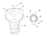
- FIG. 2Fis a perspective view of another embodiment of a cap in accordance with an exemplary embodiment of the present invention.
- FIG. 2Gis a top view of an exemplary tension spring in accordance with an exemplary embodiment of the present invention.
- FIG. 3Ais a tensioner in accordance with an exemplary embodiment of the present invention.
- FIG. 3Bis another embodiment of a tensioner in accordance with an exemplary embodiment of the present invention.
- FIG. 4Ais a fixation of a bone fracture in accordance with an exemplary embodiment of the present invention.
- FIGS. 4B-4Dare fixations of fractures of a certain portions of a bone in accordance with an exemplary embodiment of the present invention.
- FIG. 4Eis a fixation of a bone fracture by inserting the lagwire through the entire limb to facilitate attaching an external fixation device to the limb in accordance with an exemplary embodiment of the present invention.
- FIGS. 4F-4Gis a fixation of a bone fracture by inserting the lagwire through the entire limb to facilitate holding a plate to the bone to help fix certain types of fractures in accordance with an exemplary embodiment of the present invention.
- FIG. 4His a fixation of a spinal injury in accordance with an exemplary embodiment of the present invention.
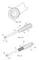
- FIG. 5Ais an exemplary head of the extractor of FIG. 5B in accordance with an exemplary embodiment of the present invention.
- FIG. 5Bis an exemplary extractor in accordance with an exemplary embodiment of the present invention.
- FIG. 5Cis another embodiment of an exemplary extractor in accordance with an exemplary embodiment of the present invention.
- FIG. 6is an exemplary cutter in accordance with an exemplary embodiment of the present invention.
- the present inventionfacilitates the change in distance between objects or surfaces, compresses objects together and/or provides a configurable or random amount of pressure between surfaces.
- the systemmay facilitate changing, maintaining, reducing and/or expanding the distance between objects.
- the applied pressuremay be suitably configured to be constant, increasing, decreasing, variable, random, and/or the like.
- the inventionincludes a device which may be fixedly or removably attached to pathology, such as to a certain portion of a bone.
- the deviceis fixedly or removably attached to the far cortex of the bone.
- the inventionincludes a device or method for retracting the attached device to reduce the distance between the surfaces of the pathology.
- the inventionincludes a device and/or method for maintaining the pressure between the surfaces of pathology.
- the lagwire system 1includes a head component 2 , a wire 12 and a cap 20 .
- the lagwire system 1may be fabricated using any type, amount or combination of materials suitably configured for the particular application.
- the lagwire system 1is fabricated with stainless steel, titanium and/or titanium alloy which minimize reactivity with the body.
- Each componentmay be fabricated with various diameters, thread pitches, lengths and/or the like.
- the head component 2is any device which is configured to fixedly or removably attach to any object, such as pathology.
- the head component 2is configured to be fixedly or removably attached to the far cortex of the bone, as shown in FIGS. 4A-4G . As best shown in FIG.
- the head component 2may include, for example, a self drilling tip 4 device which is suitably configured to puncture a hole and/or guide the head component 2 , self cutting threads 6 which are suitably configured to cut thread grooves into the inside surface of a hole, fastening threads 8 which are suitably configured to mate with the newly formed thread grooves, and a tool attachment 10 suitably configured for mating with a tool head (e.g., hex head wrench, socket wrench, Phillips screwdriver, flathead screwdriver, allan wrench and/or the like).
- Head component 2may include different thread configurations, lengths, diameters, pitches and the like to facilitate insertion into different types of bone or other structures (e.g., cortical bone, cancellous bone, etc).
- the tipis on the front end of head component 2 , followed by the cutting threads 6 , the fastening threads 8 , the tool attachment 10 , then wire 12 .
- the elements of head component 2may be fabricated as one component or one or more elements may be configured to be removably or fixedly mated together to form head component 2 . If mated together, a particular element may be exchanged for different applications. For example, if head component 2 needs to be inserted into a dense or hard bone, a stronger or sharper tip 4 may be screwed into thread element 6 . 8 . Moreover, if deeper thread grooves are desired, cutting threads 6 may be replaced with greater diameter threads. Furthermore, if a different tool head is incorporated into a drill, tool attachment 10 may be exchanged with the appropriate attachment.
- the outside diameter of the fastening threadsare similar to the thread diameters of known surgical screw sizes.
- Exemplary outside diameters of cortical head componentsinclude 3.5 mm and 4.5 mm, wherein the length of the thread section is similar to the cortex thickness.
- Exemplary outside diameters of cancellous (i.e., little or no cortex) head componentsinclude about 4.0 mm and 6.5 mm, wherein the length of the thread section may be about 16 mm or 32 mm.
- Wire 12is any device suitably configured, when tension is applied, to reduce the distance between two surfaces.
- wire 12is configured to retract the head component 2 device to reduce the distance between the surfaces of the pathology.
- head component 2 and wire 12are constructed as one component.
- head component 2 and wire 12are constructed as separate components, but the components are configured such that the head component 2 may be threaded onto wire 12 after wire 12 is placed into the bone.
- Wire 12further includes an interface component 14 on at least a portion of its surface, wherein the interface component 14 is suitably configured to limit the movement of cap 20 to move distally toward head component 2 , but not proximally (backwards).
- interface component 14 of wire 12includes a sawtooth like configuration such that one side of each tooth (e.g. the side closest to head component 2 ) is substantially perpendicular to the surface of wire 12 , while the other side of the sawtooth is at a suitable angle, such as 45 degrees, thereby forming a triangular pattern for each sawtooth.
- a suitable anglesuch as 45 degrees
- any portion or the entire length of wire 12includes any configuration such as, for example, round, oval, flat on one or more portions of the wire, and/or microgrooves or ridges along the wire (which may include the sawtooth configuration, indentions or other configurations) to increase the friction along the wire.
- wire 12holds 20 pounds of pull; however, microgrooves in the wire may significantly increase the strength of the wire 12 .
- wire 12is comprised of a thin metal such as, for example, stainless steel, titanium and/or titanium alloy, so it may be easily cut to almost any desired length, thereby eliminating or reducing the need for fixed lengths screws.
- the inventionsubstantially reduces or eliminates the need for the inventory or availability of large screw sets or multiple screws.
- the systemmay include numerous materials, configurations and designs for either wire 12 or cap 20 , the invention provides increased versatility because the physician is provided with multiple options and choices for wire 12 and cap 20 combinations.
- Cap 20is any device suitably configured to maintain or increase the pressure between the surfaces of pathology by limiting wire 12 movement. As shown in FIGS. 2A-2E , exemplary caps 20 may include various configurations, materials, shapes and/or sizes. In one embodiment, and as shown in FIG. 2A , cap 20 includes an inverse interface component 22 relative to wire 12 interface component such that cap 20 is restricted from backwards translation after cap 20 is inserted over wire 12 . In one embodiment, the interface component 22 on cap 20 is located at least on the inside surface of the cap and includes a saw tooth pattern with the same or similar pitch as the saw tooth on wire 12 .
- cap 20also allows cap 20 to slide along wire 12 without the need for spinning cap 20 which is important because time is of the essence in a medical procedure and spinning the cap down a sufficiently long length of wire would be very time-consuming.
- Examples of cap 20include a screw cap 20 , flat cap 20 and a quick cap 20 .
- screw cap 20is configured with teeth 22 , cutting threads 24 and/or mating threads 26 on the outside surface to facilitate rotating cap 20 into the cortex to, for example, fix surgical plates against certain pathology.
- flat cap 20may include teeth 22 , cutting threads 24 and/or mating threads 26 on the outside surface to facilitate rotating cap 20 into the cortex, but it also is configured with a flat top surface 28 to allow cap 20 to be inserted into the cortex such that the flat top surface 28 of cap 20 does not substantially protrude from the cortex surface.
- the quick cap 20 or any other capmay be configured with only the interface component on the inside surface, thereby allowing for quick and easy assembly.
- cap 20is configured as a planar disk 30 with a center hole 32 , wherein the center hole 32 includes an interface component 34 on its inner circumference surface.
- the pitch of the saw tooth interface componentis about 0.25 mm-0.5 mm.
- the planar disk 30may also include any configuration for facilitating expansion of the disk 36 while sliding down wire 12 .
- the configurationsmay include, for example, a cut 38 or a hole 36 in the planar disk 30 .
- the planar diskmay include multiple holes or cuts spaced over the planar surface.
- One or more of the additional holes 36may also be connected to a cut 38 in the planar surface that extends to the center hole 32 .
- One or more of the holes 36may also be connected to a cut 40 in the planar surface that extends to the outside edge of the planar surface.
- six additional holes 36are evenly spaced around the planar surface with each hole 36 connected to a cut 38 which extends to the center hole, while one hole 36 also includes a cut 40 that extends to the outside edge of the planar surface.
- the planar diskmay also set inside a shallow cup device, wherein the circumference of the cup is slightly larger than the circumference of the planar ring in order to allow expansion of the ring.
- a springor any other device suitably configured to apply pressure to cap 20 , is placed between the planar ring and the cup device.
- a bellville springis used to apply pressure to the cap 20 .
- the springis configured to provide tension on wire 12 after resorption. During the healing process, cartilage forms at the break and the cartilage compresses, so bone resorption typically occurs at the location of the fracture.
- cap 20allows for auto tightening of the lagwire because micro-motions or vibrations will often cause cap interface device 22 to click down another notch on the inverse interface device of the wire 12 .
- cap 20fits over one end of wire 12 , such that cap 20 permits travel of cap 20 in one direction (e.g., distal travel with respect to the wire, toward the bone), but resists travel of cap 20 in the other direction (e.g., proximal travel with respect to the wire, away from the bone).
- cap 20includes cutting threads 26 , cover 70 , a tension spring 80 and substantially flat surfaces 76 around the circumference of cap 20 to facilitate griping and/or turning cap 20 .
- Cap 20may be configured with a wider upper section which includes flat surfaces 76 around its circumference, and a tapered lower section with a gradually reducing diameter. Cutting threads 26 extend from the lower section.
- Cap 20may include different thread configurations, lengths, diameters, pitches and the like to facilitate insertion into different types of bone or other structures (e.g., cortical bone, cancellous bone, etc).
- Cover 70may be integral with cap 20 , or may be a separate component which is permanently or temporarily set in, or affixed to, cap 20 .
- cover 70includes an opening 72 (e.g., in center of cover 70 ) which receives wire 12 and an inlet 74 which is configured to receive a component of extractor tool 90 .
- tension spring 80is set inside cap 20 .
- tension spring 20sits within cap 20 below cover 70 ; is circular; includes opening 84 (e.g., in center of circular ring) which receives wire 12 ; includes an outer ring 82 and an inner ring 83 ; includes a cut into, or non-connecting portion 86 of, outer ring 82 and/or inner ring 83 ; and/or includes a tab 88 which extends outward from outer ring 82 .
- Outer ring 82 and an inner ring 83may be one integrated ring, or two or more separate rings, which may not be connected, or may be connected in any manner.
- At least a portion of inner ring 83(or any portion of inner circumference of tension spring 80 ) provides greater friction against wire 12 one way (e.g., when the cap is pulled proximal, away from the bone).
- the frictionis asserted against wire 12 because cover 70 impacts tab 88 , so tab 88 forces tension spring 80 to flex, torque and/or tilt (e.g., 15 degrees) opening 84 , thereby causing at least a portion of inner ring 83 to assert friction against at least a portion of wire 12 .
- tab 88is forced away from cover 70 and does not tilt, so it does not engage any surface, and the wire is able to translate, with minimal or no friction, through the central opening in the tension spring.
- Extractor/Driver 90includes any device suitably configured to insert and/or extract cap 20 .
- extractor 90includes one or more ball bearings 91 , shaft 95 , shaft end 93 , handle 92 which receives shaft end 93 , tip sleeve 94 , tip 96 , and/or spring 97 .
- Tip 96may be the end of a long rod which extends upward into handle 92 .
- Spring 97applies pressure against the upper end of the rod that emanates from tip 96 , thereby asserting a load against tip 96 .
- Tip 96is thus configured to be received into inlet 74 of cap 20 and the spring-load maintains tip 96 in inlet 74 .
- Tip sleeve 94is configured to receive cap 20 to also facilitate rotation and/or translation of cap 20 .
- Tip 96is mounted on a disc such that it allows tip sleeve 94 to more fully receive cap 20 . The disc also rotates such that extractor 90 may rotate around cap 20 , with minimal or no movement of tip 96 .
- Ball bearings 91are configured to facilitate rotation of tip sleeve 94 around outer surface of cap 20 .
- the rodmay have a first end which includes tip 96 , and a second end 98 which may exit handle 92 such that the user may apply pressure to the second end 98 of the rod, thereby similarly applying pressure and a load against tip 96 .
- Exit handle 92also rotates such that it enables rotation of tip 96 which allows the user to rotate tip 96 until tip 96 mates with the inlet in cap 20 .
- collet sleeve 99is attached to collet advancing handle 89 .
- Collet advancing handle 89includes a threaded inner surface which is configured to advance shaft 95 , and thus, advance collet sleeve 99 forward over cap 20 to facilitate grasping of cap 20 for removal of cap 20 .
- tensioner 50may also be used in conjunction with the present invention.
- tensioner 50is any device suitably configured to insert a cap 20 into an object and/or provide tension to a wire 12 .
- tensioner 50increases the pressure between the surfaces of pathology by providing tension to a wire 12 while the head component 2 of wire 12 is fixed into a bone or far cortex.
- tensioner 50includes a handle 52 with a hand trigger 54 , wherein the handle 52 supports a rotatable barrel 56 which mates with a cylindrical rod 58 .
- Cylindrical rod 58may be cannulated to receive wire 12 and/or have a driver 60 (e.g., hex, phillips, screw, allen and/or the like) at its distal end for mating with the tool attachment 10 of head component 2 .
- the barrel 56may be rotated manually or automatically in order to rotate the driver 60 into the object (e.g., bone or cortex).
- tensioner 50includes a means for exerting a force on wire 12 , such as, for example, internal gears 64 , wherein the gears 64 include an interface component 66 (e.g., saw tooth) which mate with the inverse sawtooth 20 on wire 12 .
- the tensioner 50may also include a gauge type device or any other device which is suitably configured to measure and/or display the tension exerted on wire 12 .
- tensioner 100includes a base 101 , a DVR connect component 102 , a handle 103 , a lock 104 , and/or a spring link 106 .
- Tensioner 100is configured to accept multiple size wires and may include an indicator to show the amount of tension being applied.
- Tensioner 100is also configured such that extractor 90 may clip into tensioner 100 .
- cutter 200may be used.
- Cutter 200includes insert left 201 , insert right 202 , jaw left 203 , jaw right 204 , cutter left 205 , and cutter right 206 .
- Cutter 200includes a cutting surface that extends beyond the main body of cutter 200 such that the wire may be cut from various angles.
- a cannulated lagwire driveris suitably attached to a surgical drill, such that the drill allows for automatic rotation of the driver.
- the wire 12 of lagwire system 1is placed into the channel of the driver such that the end of the driver encompasses or is received into driver head 10 of head component 2 , thereby allowing wire 12 to be drilled into the bone.
- head component 2is configured with a hex head as the driver head 10 such that the driver suitably mates to the hex head.
- the head component 2 and wire 12are then drilled into the bone to a desired depth using the automatic surgical drill (or any other manual or automatic device for rotating head component 2 ).
- drill tip 4 of head component 2facilitates the drilling of a pilot hole, wherein the proximal cutting threads 6 tap the bone for threading the inner surface of the hole, then the proximal mating threads 8 rotationally mate with the newly created threaded surface, thereby temporarily attaching the head component 2 into the cortex of the bone.
- a lagwire tensioneris used to exert tension on the lagwire.
- a lagwire tensioner 50may be used to force or seat cap 20 into the bone surface or any other desired position.
- the hex head 60 of the tensioner 50may be used to screw cap 20 into the bone surface.
- the lagwire tensioner 50exerts tension on the lagwire 12 up to a desired tension which may be read from a gauge communicating with the tensioner.
- the excess wire 12may be suitably removed by, for example, a wire cutter or any other suitable device.
- a crimp type devicemay be placed on wire 12 to also help maintain tension.
- the crimpmay include a clamp type device, bending the existing wire 12 , screwing a nut onto the end of wire 12 and/or the like.
- the crimpmay be placed on wire 12 after cap 20 is set in place, for example, in order to crimp other end pieces together.
- the tensioner 50may also be used to reverse screw cap 20 in order to remove a wire 12 out of the bone.
- the present inventionallows the lagwire to be pushed through the opposite side of the bone and through the skin such that the head component 2 of wire 12 can be suitably removed (e.g., cut off) and a cap 20 can be placed onto that end of the lagwire, thereby resulting in better purchase (e.g., quality of fixation) of the bone.
- FIGS. 4A-4Gthe lagwire system discussed herein can be used for the fixation of various types of bone fractures.
- FIG. 4Ashows the use of the present invention for an exemplary fixation of a bone fracture or break.
- FIGS. 4B-4Dshow the use of the present invention for an exemplary fixation of fractures of certain portions of bones.
- the lagwire system 1may also be used in a similar manner discussed herein in order to assist in holding a plate to the bone to help fix certain types of fractures.
- the lagwiremay be placed through an entire limb to, for example, attach an external fixation device to the limb as shown in exemplary FIG. 4E .
- FIG. 4Hshows a fixation of a vertebrae in accordance with an exemplary embodiment of the present invention.
- the screwis inserted into the vertebrae, then a cap is fitted onto the end of the wire.
- the capis specially constructed such that the cap attaches to a rod.
- the rodmay extend along various vertebrae such that the lagwires may extend from various vertebrae and all connect to the same rod.
- Another screw and lagwiremay be inserted into the other side of the vertebrae such that the wire extends from the other side of the vertebrae and its cap connects to a second rod on the other side of the vertebrae for additional stability.
- the system and method of the present inventionprovides a device which is self-drilling, self-tapping and can be inserted under power.
- the inventionalso facilitates reducing and fixing fractures in one step.
- the inventionsubstantially expedites the process for fixation of bone fractures which is, of course, critical during trauma situations in order to stabilize a patient or to minimize the amount of time the patient is on the operating table or under anesthesia.
- the present inventionprovides the ability for two sides of cortex lag screw fixation.
- the inventionenables sufficient fixation even in poor quality bone material.
- the present inventiondoes not require the use of cannulated screws. Because the lagwire includes a tip 4 which creates a pilot hole, taps the bone for threads and fixes the threads into the bone, the system and method minimizes the possibility of inaccurate placement into the distal cortex or missing the distal hole.
- the physiciantypically cuts a relatively large opening in the skin in order to locate the bone segments, pull the bone segments into alignment, then place the screw into the bones.
- the systemfacilitates the percutaneus technique by allowing the physician to cut a minor incision into the skin for the head component, insert the head component, then pull the bones together with wire 12 and set the cap, all without large incisions or additional incisions.
- the present inventionis described herein in connection with the fixation of bone fractures; however, one skilled in the art will appreciate that the lagwire system or method described herein may also be used for changing, maintaining, reducing or expanding the distance between objects or surfaces, compressing objects together or providing pressure to surfaces.
- the present inventionmay be used to repair wood products, tree limb damage, breaks in supports or columns, cracks in sculptures or buildings, breaks in sections of concrete or other building materials, cracks or breaks in car parts and/or the like.
Landscapes
- Health & Medical Sciences (AREA)
- Orthopedic Medicine & Surgery (AREA)
- Surgery (AREA)
- Life Sciences & Earth Sciences (AREA)
- Heart & Thoracic Surgery (AREA)
- Nuclear Medicine, Radiotherapy & Molecular Imaging (AREA)
- Engineering & Computer Science (AREA)
- Biomedical Technology (AREA)
- Medical Informatics (AREA)
- Molecular Biology (AREA)
- Animal Behavior & Ethology (AREA)
- General Health & Medical Sciences (AREA)
- Public Health (AREA)
- Veterinary Medicine (AREA)
- Neurology (AREA)
- Surgical Instruments (AREA)
Abstract
Description
Claims (12)
Priority Applications (20)
| Application Number | Priority Date | Filing Date | Title |
|---|---|---|---|
| US11/678,473US8679167B2 (en) | 2001-10-18 | 2007-02-23 | System and method for a cap used in the fixation of bone fractures |
| US11/742,457US8702768B2 (en) | 2001-10-18 | 2007-04-30 | Cannulated bone screw system and method |
| US11/952,715US8828067B2 (en) | 2001-10-18 | 2007-12-07 | Bone screw system and method |
| US11/952,413US20080147126A1 (en) | 2001-10-18 | 2007-12-07 | System and method for a cap used in the fixation of bone fractures |
| US12/104,328US20080243132A1 (en) | 2001-10-18 | 2008-04-16 | Tensioning system and method for the fixation of bone fractures |
| US12/104,658US20080243191A1 (en) | 2001-10-18 | 2008-04-17 | Adjustable bone plate fixation system and metho |
| US12/163,122US20090048606A1 (en) | 2001-10-18 | 2008-06-27 | Guide system and method for the fixation of bone fractures |
| US12/235,405US20090131936A1 (en) | 2001-10-18 | 2008-09-22 | System and method for the fixation of bone fractures |
| US12/258,013US20090131990A1 (en) | 2001-10-18 | 2008-10-24 | Bone screw system and method |
| US12/265,890US20090131991A1 (en) | 2001-10-18 | 2008-11-06 | System and method for the fixation of bone fractures |
| US12/369,589US20090254089A1 (en) | 2001-10-18 | 2009-02-11 | Stabilization system and method for the fixation of bone fractures |
| US12/491,132US20090306718A1 (en) | 2001-10-18 | 2009-06-24 | Filament and cap systems and methods for the fixation of bone fractures |
| US12/769,529US20100268285A1 (en) | 2001-10-18 | 2010-04-28 | Bone screw system and method for the fixation of bone fractures |
| US12/860,122US20100312292A1 (en) | 2001-10-18 | 2010-08-20 | Lagwire system and method for the fixation of bone fractures |
| US12/860,178US20100312245A1 (en) | 2001-10-18 | 2010-08-20 | Bone screw system and method for the fixation of bone fractures |
| US12/898,975US20110034925A1 (en) | 2001-10-18 | 2010-10-06 | Lagwire system and method for the fixation of bone fractures |
| US13/118,871US9060809B2 (en) | 2001-10-18 | 2011-05-31 | Lagwire system and method for the fixation of bone fractures |
| US14/449,555US9028534B2 (en) | 2001-10-18 | 2014-08-01 | Bone screw system and method |
| US14/683,478US20150223843A1 (en) | 2001-10-18 | 2015-04-10 | Bone screw system and method |
| US14/714,700US20150250503A1 (en) | 2001-10-18 | 2015-05-18 | Lagwire system and method for the fixation of bone fractures |
Applications Claiming Priority (4)
| Application Number | Priority Date | Filing Date | Title |
|---|---|---|---|
| US33018701P | 2001-10-18 | 2001-10-18 | |
| US10/272,773US6736819B2 (en) | 2001-10-18 | 2002-10-17 | System and method for fixation of bone fractures |
| US10/779,892US7591823B2 (en) | 2001-10-18 | 2004-02-17 | System and method for the fixation of bone fractures |
| US11/678,473US8679167B2 (en) | 2001-10-18 | 2007-02-23 | System and method for a cap used in the fixation of bone fractures |
Related Parent Applications (1)
| Application Number | Title | Priority Date | Filing Date |
|---|---|---|---|
| US10/779,892Continuation-In-PartUS7591823B2 (en) | 2001-10-18 | 2004-02-17 | System and method for the fixation of bone fractures |
Related Child Applications (2)
| Application Number | Title | Priority Date | Filing Date |
|---|---|---|---|
| US11/742,457Continuation-In-PartUS8702768B2 (en) | 2001-10-18 | 2007-04-30 | Cannulated bone screw system and method |
| US11/952,413Continuation-In-PartUS20080147126A1 (en) | 2001-10-18 | 2007-12-07 | System and method for a cap used in the fixation of bone fractures |
Publications (2)
| Publication Number | Publication Date |
|---|---|
| US20070162026A1 US20070162026A1 (en) | 2007-07-12 |
| US8679167B2true US8679167B2 (en) | 2014-03-25 |
Family
ID=38233668
Family Applications (1)
| Application Number | Title | Priority Date | Filing Date |
|---|---|---|---|
| US11/678,473Expired - LifetimeUS8679167B2 (en) | 2001-10-18 | 2007-02-23 | System and method for a cap used in the fixation of bone fractures |
Country Status (1)
| Country | Link |
|---|---|
| US (1) | US8679167B2 (en) |
Cited By (13)
| Publication number | Priority date | Publication date | Assignee | Title |
|---|---|---|---|---|
| US20150223843A1 (en)* | 2001-10-18 | 2015-08-13 | Orthoip, Llc | Bone screw system and method |
| US9827028B2 (en)* | 2010-02-26 | 2017-11-28 | Biedermann Technologies Gmbh & Co. Kg | Bone screw |
| US10136929B2 (en) | 2015-07-13 | 2018-11-27 | IntraFuse, LLC | Flexible bone implant |
| US10154863B2 (en) | 2015-07-13 | 2018-12-18 | IntraFuse, LLC | Flexible bone screw |
| US10485595B2 (en) | 2015-07-13 | 2019-11-26 | IntraFuse, LLC | Flexible bone screw |
| US10499960B2 (en) | 2015-07-13 | 2019-12-10 | IntraFuse, LLC | Method of bone fixation |
| US10575883B2 (en) | 2014-12-15 | 2020-03-03 | Smith & Nephew, Inc. | Active fracture compression implants |
| US11317956B1 (en) | 2021-08-26 | 2022-05-03 | University Of Utah Research Foundation | Active compression bone screw |
| US11607323B2 (en) | 2018-10-15 | 2023-03-21 | Howmedica Osteonics Corp. | Patellofemoral trial extractor |
| US11998255B1 (en) | 2023-08-26 | 2024-06-04 | University Of Utah Research Foundation | Cannulated continuous compression screw |
| USD1037845S1 (en)* | 2022-11-08 | 2024-08-06 | Madhu Sudan Saini | Screw |
| US12226135B1 (en) | 2024-02-13 | 2025-02-18 | Surgeon Design Center LLC. | Surgical guide wire engagement device |
| US12426871B2 (en) | 2022-08-24 | 2025-09-30 | Globus Medical, Inc. | Systems, devices and methods for implanting suture buttons |
Families Citing this family (15)
| Publication number | Priority date | Publication date | Assignee | Title |
|---|---|---|---|---|
| US6736819B2 (en) | 2001-10-18 | 2004-05-18 | Kishore Tipirneni | System and method for fixation of bone fractures |
| US8679167B2 (en) | 2001-10-18 | 2014-03-25 | Orthoip, Llc | System and method for a cap used in the fixation of bone fractures |
| US20100268285A1 (en)* | 2001-10-18 | 2010-10-21 | Orthoip, Llc | Bone screw system and method for the fixation of bone fractures |
| US8702768B2 (en) | 2001-10-18 | 2014-04-22 | Orthoip, Llc | Cannulated bone screw system and method |
| US9060809B2 (en) | 2001-10-18 | 2015-06-23 | Orthoip, Llc | Lagwire system and method for the fixation of bone fractures |
| US20100312292A1 (en)* | 2001-10-18 | 2010-12-09 | Orthoip, Llc | Lagwire system and method for the fixation of bone fractures |
| WO2007117571A2 (en)* | 2006-04-06 | 2007-10-18 | Lotus Medical, Llc | Active compression to facilitate healing of bones |
| HK1201138A1 (en) | 2011-10-10 | 2015-08-28 | William Casey Fox | Shape changing bone implant for enhanced healing |
| US9730737B2 (en)* | 2013-03-14 | 2017-08-15 | Atlas Spine, Inc. | Facet fixation with anchor wire |
| US10064670B2 (en)* | 2014-05-12 | 2018-09-04 | DePuy Synthes Products, Inc. | Sacral fixation system |
| CA2949060A1 (en)* | 2014-05-12 | 2015-11-19 | DePuy Synthes Products, Inc. | Sacral fixation system |
| WO2016070191A1 (en) | 2014-11-01 | 2016-05-06 | Numagenesis, Llc (State Of North Carolina) | Compression fixation system |
| CN107536638A (en)* | 2017-06-13 | 2018-01-05 | 马克 | A kind of surgical instrument assemblies for fracture fixation |
| WO2019213560A1 (en) | 2018-05-04 | 2019-11-07 | Numagenesis, Llc (State Of North Carolina) | Compression fixation system |
| US20220047311A1 (en)* | 2020-08-17 | 2022-02-17 | Ahmad N. Ali | Surgical Method of Stabilizing Bone or Joint Fracture Using Flexible Line |
Citations (167)
| Publication number | Priority date | Publication date | Assignee | Title |
|---|---|---|---|---|
| US1025008A (en) | 1911-08-07 | 1912-04-30 | Lucien Luttrell Miner | Brace for fractured bones. |
| US2077804A (en) | 1936-05-19 | 1937-04-20 | Morrison Gordon Monroe | Device for treating fractures of the neck of the femur |
| US2381050A (en) | 1943-12-04 | 1945-08-07 | Mervyn G Hardinge | Fracture reducing device |
| US2397545A (en) | 1945-02-13 | 1946-04-02 | Mervyn G Hardinge | Self-adjusting fracture reducing device |
| US2414882A (en) | 1943-09-24 | 1947-01-28 | Herschel Leiter H | Fracture reduction apparatus |
| US2490364A (en) | 1948-02-27 | 1949-12-06 | Herman H Livingston | Bone pin |
| US2511051A (en)* | 1946-06-19 | 1950-06-13 | Dzus William | Fastening device |
| US3051169A (en) | 1957-12-07 | 1962-08-28 | Stille Werner Ab | Surgical screw connector |
| US3433220A (en) | 1966-12-30 | 1969-03-18 | Robert E Zickel | Intramedullary rod and cross-nail assembly for treating femur fractures |
| US3489143A (en) | 1967-12-15 | 1970-01-13 | William X Halloran | Convertible hip pin |
| US4456005A (en) | 1982-09-30 | 1984-06-26 | Lichty Terry K | External compression bone fixation device |
| US4617922A (en) | 1982-01-18 | 1986-10-21 | Richards Medical Company | Compression screw assembly |
| US4621629A (en)* | 1985-08-12 | 1986-11-11 | Harrington Arthritis Research Center | Compression hip screw |
| US4632100A (en) | 1985-08-29 | 1986-12-30 | Marlowe E. Goble | Suture anchor assembly |
| US4640271A (en) | 1985-11-07 | 1987-02-03 | Zimmer, Inc. | Bone screw |
| US4708132A (en) | 1986-01-24 | 1987-11-24 | Pfizer-Hospital Products Group, Inc. | Fixation device for a ligament or tendon prosthesis |
| US4741330A (en) | 1983-05-19 | 1988-05-03 | Hayhurst John O | Method and apparatus for anchoring and manipulating cartilage |
| US4773406A (en) | 1984-01-13 | 1988-09-27 | Ed. Geistlich Sohne Ag Fur Chemische Industrie | Bone fracture fixation plates |
| US4858601A (en) | 1988-05-27 | 1989-08-22 | Glisson Richard R | Adjustable compression bone screw |
| US4863383A (en) | 1987-03-17 | 1989-09-05 | Grafelmann Hans L | self-taping screw-in bone implant for dental purposes |
| US4889110A (en) | 1987-05-05 | 1989-12-26 | Yves Galline | Attaching device and tools for positioning same, especially for attaching the trochanter major to the femur |
| US4905680A (en) | 1986-10-27 | 1990-03-06 | Johnson & Johnson Orthopaedics, Inc. | Absorbable bone plate |
| US4934935A (en) | 1986-10-21 | 1990-06-19 | Edwards Barry N | Dental prostheses |
| US4940467A (en) | 1988-02-03 | 1990-07-10 | Tronzo Raymond G | Variable length fixation device |
| US4959064A (en)* | 1988-10-07 | 1990-09-25 | Boehringer Mannheim Corporation | Dynamic tension bone screw |
| US5019079A (en) | 1989-11-20 | 1991-05-28 | Zimmer, Inc. | Bone screw |
| US5041116A (en) | 1990-05-21 | 1991-08-20 | Wilson James T | Compression hip screw system |
| US5061137A (en) | 1991-04-29 | 1991-10-29 | Ford Motor Company | Fastener with resilient linking means |
| US5100405A (en) | 1990-09-07 | 1992-03-31 | Mclaren Alexander C | Locking cap for medical implants |
| US5102276A (en) | 1990-07-12 | 1992-04-07 | Ford Motor Company | Removable fastener with elastic linking means |
| US5116340A (en) | 1989-01-26 | 1992-05-26 | Songer Robert J | Surgical securance apparatus |
| US5116336A (en) | 1990-03-19 | 1992-05-26 | Synthes (U.S.A.) | Osteosynthetic anchor bolt |
| US5122133A (en) | 1990-10-26 | 1992-06-16 | Smith & Nephew Richards Inc. | Compression screw for a joint endoprosthesis |
| US5127914A (en) | 1989-02-10 | 1992-07-07 | Calderale Pasquale M | Osteosynthesis means for the connection of bone fracture segments |
| US5129901A (en) | 1991-06-10 | 1992-07-14 | Decoste Vern X | Cannulated orthopedic screw |
| US5141520A (en)* | 1991-10-29 | 1992-08-25 | Marlowe Goble E | Harpoon suture anchor |
| US5207753A (en) | 1991-02-18 | 1993-05-04 | Kannivelu Badrinath | Bone fracture repair apparatus and method |
| US5217462A (en)* | 1991-03-05 | 1993-06-08 | Pfizer Hospital Products Group, Inc. | Screw and driver |
| US5269784A (en) | 1991-12-10 | 1993-12-14 | Synthes (U.S.A.) | Screw nut for plate osteosynthesis |
| US5300075A (en) | 1991-09-18 | 1994-04-05 | Gordon Donn M | Cover for orthopedic splinting rods and method of installation |
| US5306290A (en) | 1993-02-12 | 1994-04-26 | Mitek Surgical Products, Inc. | Suture button |
| US5324292A (en) | 1993-02-10 | 1994-06-28 | Zimmer, Inc. | Fracture fixation assembly with selectively removable protrusion |
| US5336028A (en) | 1993-04-13 | 1994-08-09 | Vsi Corporation | Captive screw assembly |
| US5338139A (en) | 1993-10-20 | 1994-08-16 | Penn Engineering & Manufacturing Corp. | Shrouded captive screw |
| US5364398A (en) | 1986-06-23 | 1994-11-15 | Pfizer Hospital Products Group, Inc. | Modular femoral fixation system |
| US5368605A (en) | 1993-03-09 | 1994-11-29 | Miller, Jr.; Herman A. | Laparoscopic surgical instrument |
| US5382124A (en) | 1994-02-07 | 1995-01-17 | Southco, Inc. | Fully retractable captive screw |
| US5409493A (en) | 1990-07-13 | 1995-04-25 | Greenberg; Alex M. | Single-handed surgical drill depth guide |
| US5417692A (en) | 1994-01-04 | 1995-05-23 | Goble; E. Marlowe | Bone fixation and fusion system |
| US5423820A (en) | 1993-07-20 | 1995-06-13 | Danek Medical, Inc. | Surgical cable and crimp |
| US5431660A (en) | 1993-11-30 | 1995-07-11 | Burke; Dennis W. | Spring loaded screw and driver/extractor therefor |
| US5462547A (en) | 1991-05-30 | 1995-10-31 | Synthes (U.S.A.) | Trochanter stabilization device |
| US5507801A (en) | 1990-06-06 | 1996-04-16 | Synthes (U.S.A.) | Compression drill guide |
| US5520691A (en) | 1990-11-06 | 1996-05-28 | Branch; Thomas P. | Method and apparatus for re-approximating tissue |
| US5586985A (en) | 1994-10-26 | 1996-12-24 | Regents Of The University Of Minnesota | Method and apparatus for fixation of distal radius fractures |
| US5591207A (en) | 1995-03-30 | 1997-01-07 | Linvatec Corporation | Driving system for inserting threaded suture anchors |
| US5601553A (en) | 1994-10-03 | 1997-02-11 | Synthes (U.S.A.) | Locking plate and bone screw |
| US5607426A (en) | 1995-04-13 | 1997-03-04 | Fastenletix, L.L.C. | Threaded polyaxial locking screw plate assembly |
| US5611801A (en) | 1994-11-29 | 1997-03-18 | Pioneer Laboratories, Inc. | Method and apparatus for bone fracture fixation |
| US5632745A (en) | 1995-02-07 | 1997-05-27 | R&D Biologicals, Inc. | Surgical implantation of cartilage repair unit |
| US5643267A (en) | 1992-03-10 | 1997-07-01 | Asahi Kogaku Kogyo Kabushiki Kaisha | Bone connector adapted for joining cut bone ends |
| US5702397A (en) | 1996-02-20 | 1997-12-30 | Medicinelodge, Inc. | Ligament bone anchor and method for its use |
| US5709687A (en) | 1994-03-16 | 1998-01-20 | Pennig; Dietmar | Fixation pin for small-bone fragments |
| US5725582A (en) | 1992-08-19 | 1998-03-10 | Surgicraft Limited | Surgical implants |
| US5810821A (en) | 1997-03-28 | 1998-09-22 | Biomet Inc. | Bone fixation screw system |
| US5809849A (en) | 1996-02-08 | 1998-09-22 | Coffey; Kevin M. | Machine for stripping insulation from wire |
| US5827285A (en) | 1996-12-12 | 1998-10-27 | Bramlet; Dale G. | Multipiece interfragmentary fixation assembly |
| US5893859A (en) | 1997-01-14 | 1999-04-13 | Teramed, Inc. | Method for forming custom length grafts after endoluminal insertion |
| US5893850A (en)* | 1996-11-12 | 1999-04-13 | Cachia; Victor V. | Bone fixation device |
| US5899906A (en) | 1996-01-18 | 1999-05-04 | Synthes (U.S.A.) | Threaded washer |
| US5902011A (en) | 1995-06-09 | 1999-05-11 | Herman Miller, Inc. | Office chair and adjustable lumbar support therefor |
| US5928236A (en) | 1994-07-04 | 1999-07-27 | Depuy France | Locking pin or screw device for an osteosynthesis plate or for the coaptation of bone fragments |
| US5954722A (en)* | 1997-07-29 | 1999-09-21 | Depuy Acromed, Inc. | Polyaxial locking plate |
| US5964763A (en) | 1997-02-14 | 1999-10-12 | Incavo; Stephen J. | Incrementally adjustable tibial osteotomy fixation device and method |
| US5964760A (en) | 1996-10-18 | 1999-10-12 | Spinal Innovations | Spinal implant fixation assembly |
| US5976139A (en) | 1996-07-17 | 1999-11-02 | Bramlet; Dale G. | Surgical fastener assembly |
| US5984925A (en) | 1997-07-30 | 1999-11-16 | Cross Medical Products, Inc. | Longitudinally adjustable bone plates and method for use thereof |
| US5993477A (en)* | 1998-06-25 | 1999-11-30 | Ethicon Endo-Surgery, Inc. | Ultrasonic bone anchor |
| US5997538A (en) | 1998-03-23 | 1999-12-07 | New York Society For The Ruptured And Crippled Maintaining The Hospital For Special Surgery | Rotationally ratcheting bone screw |
| US6027523A (en) | 1997-10-06 | 2000-02-22 | Arthrex, Inc. | Suture anchor with attached disk |
| US6033429A (en) | 1998-01-13 | 2000-03-07 | Cardiac Assist Technologies, Inc. | System, apparatus and method for closing severed bone or tissue of a patient |
| US6039740A (en) | 1995-02-07 | 2000-03-21 | Olerud; Sven | Method and a device for implant locking |
| US6050998A (en) | 1999-05-21 | 2000-04-18 | Stephen A. Fletcher | Bone fastener |
| US6093188A (en) | 1997-11-10 | 2000-07-25 | Murray; William M. | Adjustable bone fixation plate |
| FR2784019B3 (en) | 1998-10-05 | 2000-08-04 | Jean Louis Audren | LOCKABLE ELASTIC CENTRO-MEDULAR NAIL FOR OSTEOSYNTHESIS OF HUMERUS FRACTURES |
| US6143037A (en) | 1996-06-12 | 2000-11-07 | The Regents Of The University Of Michigan | Compositions and methods for coating medical devices |
| US6171310B1 (en) | 1998-04-01 | 2001-01-09 | Aesculap Ag & Co. Kg | Device and method for handling an implant covering a bone tunnel |
| US6174006B1 (en) | 1997-07-29 | 2001-01-16 | Illinois Tool Works Inc. | Tamper resistant seal |
| US6235062B1 (en) | 1994-09-06 | 2001-05-22 | Finn Gramnas | Fastening device for prosthesis |
| US6245071B1 (en) | 1999-03-10 | 2001-06-12 | Synthes (U.S.A.) | External fixation device for bone |
| US6251111B1 (en) | 1999-10-20 | 2001-06-26 | Sdgi Holdings, Inc. | Jack for pulling a vertebral anchor |
| US6319254B1 (en) | 1999-04-22 | 2001-11-20 | Newdeal | Compression osteosynthesis screw, and an ancillaty device for use therewith |
| US6368326B1 (en)* | 1998-09-28 | 2002-04-09 | Daos Limited | Internal cord fixation device |
| US20020198527A1 (en) | 2001-06-21 | 2002-12-26 | Helmut Muckter | Implantable screw for stabilization of a joint or a bone fracture |
| US20030036761A1 (en) | 2001-07-09 | 2003-02-20 | Crista Smothers | Pharmacolgical sleeve |
| US6524313B1 (en) | 1999-10-14 | 2003-02-25 | Pega Medical | Intramedullary nail system |
| US20030083658A1 (en) | 2001-10-31 | 2003-05-01 | Ortho Development Corporation | Cervical plate for stabilizing the human spine |
| US6602293B1 (en) | 1996-11-01 | 2003-08-05 | The Johns Hopkins University | Polymeric composite orthopedic implant |
| US6605090B1 (en) | 2000-10-25 | 2003-08-12 | Sdgi Holdings, Inc. | Non-metallic implant devices and intra-operative methods for assembly and fixation |
| US6610067B2 (en) | 2000-05-01 | 2003-08-26 | Arthrosurface, Incorporated | System and method for joint resurface repair |
| US20030187440A1 (en) | 2002-03-12 | 2003-10-02 | Marc Richelsoph | Bone plate and screw retaining mechanism |
| US6629534B1 (en) | 1999-04-09 | 2003-10-07 | Evalve, Inc. | Methods and apparatus for cardiac valve repair |
| US6632224B2 (en) | 1996-11-12 | 2003-10-14 | Triage Medical, Inc. | Bone fixation system |
| US20030216780A1 (en) | 2002-05-15 | 2003-11-20 | Fitts Steven E. | Two piece cross-pin graft fixation |
| US6656185B2 (en) | 2000-10-24 | 2003-12-02 | Spineology Inc. | Tension band clip |
| US6656184B1 (en) | 2002-01-09 | 2003-12-02 | Biomet, Inc. | Bone screw with helical spring |
| US6685706B2 (en) | 2001-11-19 | 2004-02-03 | Triage Medical, Inc. | Proximal anchors for bone fixation system |
| US6736819B2 (en) | 2001-10-18 | 2004-05-18 | Kishore Tipirneni | System and method for fixation of bone fractures |
| US20040097943A1 (en) | 1996-11-21 | 2004-05-20 | Hart Rickey D. | Apparatus for anchoring autologous or artificial tendon grafts in bone |
| US20040127906A1 (en) | 2002-07-19 | 2004-07-01 | Culbert Brad S. | Method and apparatus for spinal fixation |
| US20040236424A1 (en) | 2001-05-25 | 2004-11-25 | Imaging Therapeutics, Inc. | Patient selectable joint arthroplasty devices and surgical tools facilitating increased accuracy, speed and simplicity in performing total and partial joint arthroplasty |
| US20040243129A1 (en) | 2003-05-28 | 2004-12-02 | Missoum Moumene | Double helical threaded bone screw |
| US6840953B2 (en) | 2000-12-22 | 2005-01-11 | United States Surgical Corporation | Suture screw |
| US20050010226A1 (en) | 2003-05-30 | 2005-01-13 | Grady Mark P. | Bone plate |
| US6887271B2 (en) | 2001-09-28 | 2005-05-03 | Ethicon, Inc. | Expanding ligament graft fixation system and method |
| US6887243B2 (en) | 2001-03-30 | 2005-05-03 | Triage Medical, Inc. | Method and apparatus for bone fixation with secondary compression |
| US6890333B2 (en) | 2001-03-30 | 2005-05-10 | Triage Medical, Inc. | Method and apparatus for bone fixation with secondary compression |
| US6902567B2 (en) | 2000-05-31 | 2005-06-07 | Silvana Vese | Device for fixing bone sections separated because of a fracture |
| US20050234456A1 (en) | 2004-04-16 | 2005-10-20 | Malandain Hugues F | Plate system for minimally invasive support of the spine |
| US20050263549A1 (en) | 2002-06-03 | 2005-12-01 | Scheiner Rupert C | Medical device |
| US6984241B2 (en) | 1996-09-13 | 2006-01-10 | Tendon Technology, Ltd. | Apparatus and methods for tendon or ligament repair |
| US7033363B2 (en) | 2004-05-19 | 2006-04-25 | Sean Powell | Snap-lock for drill sleeve |
| US20060129148A1 (en) | 2004-10-01 | 2006-06-15 | Simmons Edward D | Screw sleeve made of polyetheretherketone (PEEK) for augmentation of bone screw insertion in osteoporotic or revision lumbar spine instrumentation |
| US7070601B2 (en) | 2003-01-16 | 2006-07-04 | Triage Medical, Inc. | Locking plate for bone anchors |
| US20060147127A1 (en) | 2001-10-05 | 2006-07-06 | Micron Technology, Inc. | Method and apparatus for electronic image processing |
| US20060161805A1 (en) | 2005-01-14 | 2006-07-20 | Charlie Tseng | Apparatus, system, and method for differential rebuilding of a reactivated offline RAID member disk |
| US20060167457A1 (en) | 2005-01-21 | 2006-07-27 | Loubert Suddaby | Orthopedic fusion plate having both active and passive subsidence controlling features |
| US7090686B2 (en) | 1995-08-24 | 2006-08-15 | Sutura, Inc. | Suturing device and method |
| US7094239B1 (en) | 1999-05-05 | 2006-08-22 | Sdgi Holdings, Inc. | Screws of cortical bone and method of manufacture thereof |
| US7094240B2 (en) | 2003-01-10 | 2006-08-22 | Sdgi Holdings, Inc. | Flexible member tensioning instruments and methods |
| US20060248638A1 (en) | 2005-05-06 | 2006-11-09 | Geberit Technik Ag | Discharge valve for a flushing cistern |
| US7135023B2 (en) | 2003-07-07 | 2006-11-14 | Watkins William T | Compression bone screw device |
| US7147639B2 (en) | 2000-05-26 | 2006-12-12 | Orthofix S.R.L. | Disposable external fixation device |
| US7163542B2 (en) | 2004-03-30 | 2007-01-16 | Synthes (U.S.A.) | Adjustable depth drill bit |
| US7172595B1 (en) | 2000-10-03 | 2007-02-06 | Medicinelodge, Inc. | Bone fixation systems and related methods |
| US20070055249A1 (en) | 2003-06-20 | 2007-03-08 | Jensen David G | Bone plates with intraoperatively tapped apertures |
| US7189251B2 (en) | 1995-08-22 | 2007-03-13 | Orthohelix Surgical Designs, Inc. | Open helical organic tissue anchor having recessible head and method of making the organic tissue anchor |
| US20070123878A1 (en) | 2005-10-21 | 2007-05-31 | Shaver Joseph A | Orthopedic rod with locking aperture |
| US20070162026A1 (en) | 2001-10-18 | 2007-07-12 | Fxdevices Llc | System and method for a cap used in the fixation of bone fractures |
| US20070162019A1 (en) | 2005-12-21 | 2007-07-12 | Paul Burns | Resorbable anterior cervical plating system with screw retention mechanism |
| US20070190230A1 (en) | 2005-04-29 | 2007-08-16 | Trieu Hai H | Composite Spinal Fixation Systems |
| US20070233100A1 (en) | 2006-03-31 | 2007-10-04 | Metzinger Anthony J | Variable angle intramedullary nail |
| US20070260248A1 (en) | 2001-10-18 | 2007-11-08 | Fxdevices, Llc | Cannulated bone screw system and method |
| WO2007125561A1 (en) | 2006-04-28 | 2007-11-08 | Antonio Costa | Intra-bone screw for extra-dental fixing and wire with respective mutual coupling means, particularly for orthodontic use |
| US20070270847A1 (en) | 2006-04-28 | 2007-11-22 | Shaw James A | Locking compression hip screw |
| US20070276382A1 (en) | 2006-05-09 | 2007-11-29 | Synthes (U.S.A.) | Nail System and Method for An Olecranon Osteotomy |
| US20080086144A1 (en) | 2003-06-20 | 2008-04-10 | Stryker Trauma Gmbh | Drilling tool guide wire alignment device |
| US20080147127A1 (en) | 2001-10-18 | 2008-06-19 | Fxdevices, Llc | Bone screw system and method |
| US20080147126A1 (en) | 2001-10-18 | 2008-06-19 | Fxdevices, Llc | System and method for a cap used in the fixation of bone fractures |
| US20080243191A1 (en) | 2001-10-18 | 2008-10-02 | Fx Devices, Llc | Adjustable bone plate fixation system and metho |
| US20080255555A1 (en) | 2007-04-11 | 2008-10-16 | Justis Jeff R | Temporary anchorable tether systems and methods |
| US20080255621A1 (en) | 2004-06-02 | 2008-10-16 | Synthes (U.S.A.) | Sleeve |
| US20080300636A1 (en) | 2007-02-14 | 2008-12-04 | Olivier Carli | Fracture reduction instrument for osseous body |
| US7476254B2 (en) | 1993-11-01 | 2009-01-13 | Biomet Manufacturing Corporation | Compliant fixation for pelvis |
| US20090131936A1 (en) | 2001-10-18 | 2009-05-21 | Kishore Tipirneni | System and method for the fixation of bone fractures |
| US20090131990A1 (en) | 2001-10-18 | 2009-05-21 | Kishore Tipirneni | Bone screw system and method |
| US20090131991A1 (en) | 2001-10-18 | 2009-05-21 | Kishore Tipirneni | System and method for the fixation of bone fractures |
| US20090198288A1 (en) | 2008-01-31 | 2009-08-06 | Cayenne Medical, Inc. | Self-tapping biocompatible interference bone screw |
| US20090254129A1 (en) | 2007-04-30 | 2009-10-08 | Kishore Tipirneni | Bone screw system and method for the fixation of bone fractures |
| US20090306718A1 (en) | 2001-10-18 | 2009-12-10 | Orthoip, Llc | Filament and cap systems and methods for the fixation of bone fractures |
| US7641677B2 (en) | 2002-11-20 | 2010-01-05 | Orthopediatrics Corp. | Compression bone fragment wire |
| US20100114097A1 (en) | 2007-04-27 | 2010-05-06 | Synthes Usa, Llc | Implant Devices Constructed with Metallic and Polymeric Components |
| US7771428B2 (en) | 2004-06-11 | 2010-08-10 | Synthes Usa, Llc | Intramedullary rod with spiraling flutes |
| US20100312292A1 (en) | 2001-10-18 | 2010-12-09 | Orthoip, Llc | Lagwire system and method for the fixation of bone fractures |
| US20100312245A1 (en) | 2001-10-18 | 2010-12-09 | Orthoip, Llc | Bone screw system and method for the fixation of bone fractures |
| US20110034925A1 (en) | 2001-10-18 | 2011-02-10 | Orthoip, Llc | Lagwire system and method for the fixation of bone fractures |
| US20110295252A1 (en) | 2001-10-18 | 2011-12-01 | Orthoip, Llc | Lagwire system and method for the fixation of bone fractures |
Family Cites Families (4)
| Publication number | Priority date | Publication date | Assignee | Title |
|---|---|---|---|---|
| US4688561A (en)* | 1985-09-17 | 1987-08-25 | Reese H William | Bone handling apparatus and method |
| US5529075A (en)* | 1994-09-12 | 1996-06-25 | Clark; David | Fixation device and method for repair of pronounced hallux valgus |
| FR2737968B1 (en)* | 1995-08-23 | 1997-12-05 | Biomat | IMPLANT FOR OSTEOSYNTHESIS OF SUPERIOR FEMALE EPIPHYSIS |
| JP3687703B2 (en)* | 1996-07-18 | 2005-08-24 | 矢崎総業株式会社 | Pressure welding apparatus and pressure welding method |
- 2007
- 2007-02-23USUS11/678,473patent/US8679167B2/ennot_activeExpired - Lifetime
Patent Citations (177)
| Publication number | Priority date | Publication date | Assignee | Title |
|---|---|---|---|---|
| US1025008A (en) | 1911-08-07 | 1912-04-30 | Lucien Luttrell Miner | Brace for fractured bones. |
| US2077804A (en) | 1936-05-19 | 1937-04-20 | Morrison Gordon Monroe | Device for treating fractures of the neck of the femur |
| US2414882A (en) | 1943-09-24 | 1947-01-28 | Herschel Leiter H | Fracture reduction apparatus |
| US2381050A (en) | 1943-12-04 | 1945-08-07 | Mervyn G Hardinge | Fracture reducing device |
| US2397545A (en) | 1945-02-13 | 1946-04-02 | Mervyn G Hardinge | Self-adjusting fracture reducing device |
| US2511051A (en)* | 1946-06-19 | 1950-06-13 | Dzus William | Fastening device |
| US2490364A (en) | 1948-02-27 | 1949-12-06 | Herman H Livingston | Bone pin |
| US3051169A (en) | 1957-12-07 | 1962-08-28 | Stille Werner Ab | Surgical screw connector |
| US3433220A (en) | 1966-12-30 | 1969-03-18 | Robert E Zickel | Intramedullary rod and cross-nail assembly for treating femur fractures |
| US3489143A (en) | 1967-12-15 | 1970-01-13 | William X Halloran | Convertible hip pin |
| US4617922A (en) | 1982-01-18 | 1986-10-21 | Richards Medical Company | Compression screw assembly |
| US4456005A (en) | 1982-09-30 | 1984-06-26 | Lichty Terry K | External compression bone fixation device |
| US4741330A (en) | 1983-05-19 | 1988-05-03 | Hayhurst John O | Method and apparatus for anchoring and manipulating cartilage |
| US4773406A (en) | 1984-01-13 | 1988-09-27 | Ed. Geistlich Sohne Ag Fur Chemische Industrie | Bone fracture fixation plates |
| US4621629A (en)* | 1985-08-12 | 1986-11-11 | Harrington Arthritis Research Center | Compression hip screw |
| US4632100A (en) | 1985-08-29 | 1986-12-30 | Marlowe E. Goble | Suture anchor assembly |
| US4640271A (en) | 1985-11-07 | 1987-02-03 | Zimmer, Inc. | Bone screw |
| US4708132A (en) | 1986-01-24 | 1987-11-24 | Pfizer-Hospital Products Group, Inc. | Fixation device for a ligament or tendon prosthesis |
| US5364398A (en) | 1986-06-23 | 1994-11-15 | Pfizer Hospital Products Group, Inc. | Modular femoral fixation system |
| US4934935A (en) | 1986-10-21 | 1990-06-19 | Edwards Barry N | Dental prostheses |
| US4905680A (en) | 1986-10-27 | 1990-03-06 | Johnson & Johnson Orthopaedics, Inc. | Absorbable bone plate |
| US4863383A (en) | 1987-03-17 | 1989-09-05 | Grafelmann Hans L | self-taping screw-in bone implant for dental purposes |
| US4889110A (en) | 1987-05-05 | 1989-12-26 | Yves Galline | Attaching device and tools for positioning same, especially for attaching the trochanter major to the femur |
| US4940467A (en) | 1988-02-03 | 1990-07-10 | Tronzo Raymond G | Variable length fixation device |
| US4858601A (en) | 1988-05-27 | 1989-08-22 | Glisson Richard R | Adjustable compression bone screw |
| US4959064A (en)* | 1988-10-07 | 1990-09-25 | Boehringer Mannheim Corporation | Dynamic tension bone screw |
| US5116340A (en) | 1989-01-26 | 1992-05-26 | Songer Robert J | Surgical securance apparatus |
| US5127914A (en) | 1989-02-10 | 1992-07-07 | Calderale Pasquale M | Osteosynthesis means for the connection of bone fracture segments |
| US5019079A (en) | 1989-11-20 | 1991-05-28 | Zimmer, Inc. | Bone screw |
| US5116336A (en) | 1990-03-19 | 1992-05-26 | Synthes (U.S.A.) | Osteosynthetic anchor bolt |
| US5041116A (en) | 1990-05-21 | 1991-08-20 | Wilson James T | Compression hip screw system |
| US5507801A (en) | 1990-06-06 | 1996-04-16 | Synthes (U.S.A.) | Compression drill guide |
| US5102276A (en) | 1990-07-12 | 1992-04-07 | Ford Motor Company | Removable fastener with elastic linking means |
| US5409493A (en) | 1990-07-13 | 1995-04-25 | Greenberg; Alex M. | Single-handed surgical drill depth guide |
| US5100405A (en) | 1990-09-07 | 1992-03-31 | Mclaren Alexander C | Locking cap for medical implants |
| US5122133A (en) | 1990-10-26 | 1992-06-16 | Smith & Nephew Richards Inc. | Compression screw for a joint endoprosthesis |
| US5520691A (en) | 1990-11-06 | 1996-05-28 | Branch; Thomas P. | Method and apparatus for re-approximating tissue |
| US5207753A (en) | 1991-02-18 | 1993-05-04 | Kannivelu Badrinath | Bone fracture repair apparatus and method |
| US5217462A (en)* | 1991-03-05 | 1993-06-08 | Pfizer Hospital Products Group, Inc. | Screw and driver |
| US5061137A (en) | 1991-04-29 | 1991-10-29 | Ford Motor Company | Fastener with resilient linking means |
| US5462547A (en) | 1991-05-30 | 1995-10-31 | Synthes (U.S.A.) | Trochanter stabilization device |
| US5129901A (en) | 1991-06-10 | 1992-07-14 | Decoste Vern X | Cannulated orthopedic screw |
| US5300075A (en) | 1991-09-18 | 1994-04-05 | Gordon Donn M | Cover for orthopedic splinting rods and method of installation |
| US5141520A (en)* | 1991-10-29 | 1992-08-25 | Marlowe Goble E | Harpoon suture anchor |
| US5269784A (en) | 1991-12-10 | 1993-12-14 | Synthes (U.S.A.) | Screw nut for plate osteosynthesis |
| US5643267A (en) | 1992-03-10 | 1997-07-01 | Asahi Kogaku Kogyo Kabushiki Kaisha | Bone connector adapted for joining cut bone ends |
| US5725582A (en) | 1992-08-19 | 1998-03-10 | Surgicraft Limited | Surgical implants |
| US5324292A (en) | 1993-02-10 | 1994-06-28 | Zimmer, Inc. | Fracture fixation assembly with selectively removable protrusion |
| US5306290A (en) | 1993-02-12 | 1994-04-26 | Mitek Surgical Products, Inc. | Suture button |
| US5368605A (en) | 1993-03-09 | 1994-11-29 | Miller, Jr.; Herman A. | Laparoscopic surgical instrument |
| US5336028A (en) | 1993-04-13 | 1994-08-09 | Vsi Corporation | Captive screw assembly |
| US5423820A (en) | 1993-07-20 | 1995-06-13 | Danek Medical, Inc. | Surgical cable and crimp |
| US5338139A (en) | 1993-10-20 | 1994-08-16 | Penn Engineering & Manufacturing Corp. | Shrouded captive screw |
| US7476254B2 (en) | 1993-11-01 | 2009-01-13 | Biomet Manufacturing Corporation | Compliant fixation for pelvis |
| US5431660A (en) | 1993-11-30 | 1995-07-11 | Burke; Dennis W. | Spring loaded screw and driver/extractor therefor |
| US5417692A (en) | 1994-01-04 | 1995-05-23 | Goble; E. Marlowe | Bone fixation and fusion system |
| US5382124A (en) | 1994-02-07 | 1995-01-17 | Southco, Inc. | Fully retractable captive screw |
| US5709687A (en) | 1994-03-16 | 1998-01-20 | Pennig; Dietmar | Fixation pin for small-bone fragments |
| US5928236A (en) | 1994-07-04 | 1999-07-27 | Depuy France | Locking pin or screw device for an osteosynthesis plate or for the coaptation of bone fragments |
| US6235062B1 (en) | 1994-09-06 | 2001-05-22 | Finn Gramnas | Fastening device for prosthesis |
| US5601553A (en) | 1994-10-03 | 1997-02-11 | Synthes (U.S.A.) | Locking plate and bone screw |
| US5586985A (en) | 1994-10-26 | 1996-12-24 | Regents Of The University Of Minnesota | Method and apparatus for fixation of distal radius fractures |
| US5611801A (en) | 1994-11-29 | 1997-03-18 | Pioneer Laboratories, Inc. | Method and apparatus for bone fracture fixation |
| US5632745A (en) | 1995-02-07 | 1997-05-27 | R&D Biologicals, Inc. | Surgical implantation of cartilage repair unit |
| US6039740A (en) | 1995-02-07 | 2000-03-21 | Olerud; Sven | Method and a device for implant locking |
| US5591207A (en) | 1995-03-30 | 1997-01-07 | Linvatec Corporation | Driving system for inserting threaded suture anchors |
| US5607426A (en) | 1995-04-13 | 1997-03-04 | Fastenletix, L.L.C. | Threaded polyaxial locking screw plate assembly |
| US5902011A (en) | 1995-06-09 | 1999-05-11 | Herman Miller, Inc. | Office chair and adjustable lumbar support therefor |
| US7189251B2 (en) | 1995-08-22 | 2007-03-13 | Orthohelix Surgical Designs, Inc. | Open helical organic tissue anchor having recessible head and method of making the organic tissue anchor |
| US7090686B2 (en) | 1995-08-24 | 2006-08-15 | Sutura, Inc. | Suturing device and method |
| US5899906A (en) | 1996-01-18 | 1999-05-04 | Synthes (U.S.A.) | Threaded washer |
| US5997541A (en) | 1996-01-18 | 1999-12-07 | Synthes (U.S.A) | Threaded washer |
| US5809849A (en) | 1996-02-08 | 1998-09-22 | Coffey; Kevin M. | Machine for stripping insulation from wire |
| US5702397A (en) | 1996-02-20 | 1997-12-30 | Medicinelodge, Inc. | Ligament bone anchor and method for its use |
| US6695844B2 (en) | 1996-03-13 | 2004-02-24 | Orthopedic Designs, Inc. | Surgical fastener assembly |
| US6183474B1 (en) | 1996-03-13 | 2001-02-06 | Dale G. Bramlet | Surgical fastener assembly |
| US6143037A (en) | 1996-06-12 | 2000-11-07 | The Regents Of The University Of Michigan | Compositions and methods for coating medical devices |
| US5976139A (en) | 1996-07-17 | 1999-11-02 | Bramlet; Dale G. | Surgical fastener assembly |
| US6984241B2 (en) | 1996-09-13 | 2006-01-10 | Tendon Technology, Ltd. | Apparatus and methods for tendon or ligament repair |
| US5964760A (en) | 1996-10-18 | 1999-10-12 | Spinal Innovations | Spinal implant fixation assembly |
| US6602293B1 (en) | 1996-11-01 | 2003-08-05 | The Johns Hopkins University | Polymeric composite orthopedic implant |
| US6348053B1 (en) | 1996-11-12 | 2002-02-19 | Triage Medical, Inc. | Bone fixation device |
| US7008428B2 (en) | 1996-11-12 | 2006-03-07 | Triage Medical, Inc. | Bone fixation system |
| US5893850A (en)* | 1996-11-12 | 1999-04-13 | Cachia; Victor V. | Bone fixation device |
| US6632224B2 (en) | 1996-11-12 | 2003-10-14 | Triage Medical, Inc. | Bone fixation system |
| US20040097943A1 (en) | 1996-11-21 | 2004-05-20 | Hart Rickey D. | Apparatus for anchoring autologous or artificial tendon grafts in bone |
| US5827285A (en) | 1996-12-12 | 1998-10-27 | Bramlet; Dale G. | Multipiece interfragmentary fixation assembly |
| US5893859A (en) | 1997-01-14 | 1999-04-13 | Teramed, Inc. | Method for forming custom length grafts after endoluminal insertion |
| US5964763A (en) | 1997-02-14 | 1999-10-12 | Incavo; Stephen J. | Incrementally adjustable tibial osteotomy fixation device and method |
| US5810821A (en) | 1997-03-28 | 1998-09-22 | Biomet Inc. | Bone fixation screw system |
| US6174006B1 (en) | 1997-07-29 | 2001-01-16 | Illinois Tool Works Inc. | Tamper resistant seal |
| US5954722A (en)* | 1997-07-29 | 1999-09-21 | Depuy Acromed, Inc. | Polyaxial locking plate |
| US5984925A (en) | 1997-07-30 | 1999-11-16 | Cross Medical Products, Inc. | Longitudinally adjustable bone plates and method for use thereof |
| US6027523A (en) | 1997-10-06 | 2000-02-22 | Arthrex, Inc. | Suture anchor with attached disk |
| US6093188A (en) | 1997-11-10 | 2000-07-25 | Murray; William M. | Adjustable bone fixation plate |
| US6033429A (en) | 1998-01-13 | 2000-03-07 | Cardiac Assist Technologies, Inc. | System, apparatus and method for closing severed bone or tissue of a patient |
| US5997538A (en) | 1998-03-23 | 1999-12-07 | New York Society For The Ruptured And Crippled Maintaining The Hospital For Special Surgery | Rotationally ratcheting bone screw |
| US6171310B1 (en) | 1998-04-01 | 2001-01-09 | Aesculap Ag & Co. Kg | Device and method for handling an implant covering a bone tunnel |
| US5993477A (en)* | 1998-06-25 | 1999-11-30 | Ethicon Endo-Surgery, Inc. | Ultrasonic bone anchor |
| US6368326B1 (en)* | 1998-09-28 | 2002-04-09 | Daos Limited | Internal cord fixation device |
| FR2784019B3 (en) | 1998-10-05 | 2000-08-04 | Jean Louis Audren | LOCKABLE ELASTIC CENTRO-MEDULAR NAIL FOR OSTEOSYNTHESIS OF HUMERUS FRACTURES |
| US6245071B1 (en) | 1999-03-10 | 2001-06-12 | Synthes (U.S.A.) | External fixation device for bone |
| US6629534B1 (en) | 1999-04-09 | 2003-10-07 | Evalve, Inc. | Methods and apparatus for cardiac valve repair |
| US6319254B1 (en) | 1999-04-22 | 2001-11-20 | Newdeal | Compression osteosynthesis screw, and an ancillaty device for use therewith |
| US7094239B1 (en) | 1999-05-05 | 2006-08-22 | Sdgi Holdings, Inc. | Screws of cortical bone and method of manufacture thereof |
| US6050998A (en) | 1999-05-21 | 2000-04-18 | Stephen A. Fletcher | Bone fastener |
| US6524313B1 (en) | 1999-10-14 | 2003-02-25 | Pega Medical | Intramedullary nail system |
| US6251111B1 (en) | 1999-10-20 | 2001-06-26 | Sdgi Holdings, Inc. | Jack for pulling a vertebral anchor |
| US6610067B2 (en) | 2000-05-01 | 2003-08-26 | Arthrosurface, Incorporated | System and method for joint resurface repair |
| US7147639B2 (en) | 2000-05-26 | 2006-12-12 | Orthofix S.R.L. | Disposable external fixation device |
| US6902567B2 (en) | 2000-05-31 | 2005-06-07 | Silvana Vese | Device for fixing bone sections separated because of a fracture |
| US7172595B1 (en) | 2000-10-03 | 2007-02-06 | Medicinelodge, Inc. | Bone fixation systems and related methods |
| US6656185B2 (en) | 2000-10-24 | 2003-12-02 | Spineology Inc. | Tension band clip |
| US6605090B1 (en) | 2000-10-25 | 2003-08-12 | Sdgi Holdings, Inc. | Non-metallic implant devices and intra-operative methods for assembly and fixation |
| US6840953B2 (en) | 2000-12-22 | 2005-01-11 | United States Surgical Corporation | Suture screw |
| US6887243B2 (en) | 2001-03-30 | 2005-05-03 | Triage Medical, Inc. | Method and apparatus for bone fixation with secondary compression |
| US6890333B2 (en) | 2001-03-30 | 2005-05-10 | Triage Medical, Inc. | Method and apparatus for bone fixation with secondary compression |
| US6908465B2 (en) | 2001-03-30 | 2005-06-21 | Triage Medical, Inc. | Distal bone anchors for bone fixation with secondary compression |
| US20040236424A1 (en) | 2001-05-25 | 2004-11-25 | Imaging Therapeutics, Inc. | Patient selectable joint arthroplasty devices and surgical tools facilitating increased accuracy, speed and simplicity in performing total and partial joint arthroplasty |
| US20020198527A1 (en) | 2001-06-21 | 2002-12-26 | Helmut Muckter | Implantable screw for stabilization of a joint or a bone fracture |
| US20030036761A1 (en) | 2001-07-09 | 2003-02-20 | Crista Smothers | Pharmacolgical sleeve |
| US6887271B2 (en) | 2001-09-28 | 2005-05-03 | Ethicon, Inc. | Expanding ligament graft fixation system and method |
| US20060147127A1 (en) | 2001-10-05 | 2006-07-06 | Micron Technology, Inc. | Method and apparatus for electronic image processing |
| US6736819B2 (en) | 2001-10-18 | 2004-05-18 | Kishore Tipirneni | System and method for fixation of bone fractures |
| US20090177199A1 (en) | 2001-10-18 | 2009-07-09 | Lagwire, Llc | Cap device for use in the fixation of bone structures |
| US20080243191A1 (en) | 2001-10-18 | 2008-10-02 | Fx Devices, Llc | Adjustable bone plate fixation system and metho |
| US20080147126A1 (en) | 2001-10-18 | 2008-06-19 | Fxdevices, Llc | System and method for a cap used in the fixation of bone fractures |
| US20110295252A1 (en) | 2001-10-18 | 2011-12-01 | Orthoip, Llc | Lagwire system and method for the fixation of bone fractures |
| US20110034925A1 (en) | 2001-10-18 | 2011-02-10 | Orthoip, Llc | Lagwire system and method for the fixation of bone fractures |
| US20080147127A1 (en) | 2001-10-18 | 2008-06-19 | Fxdevices, Llc | Bone screw system and method |
| US20090131936A1 (en) | 2001-10-18 | 2009-05-21 | Kishore Tipirneni | System and method for the fixation of bone fractures |
| US20100312245A1 (en) | 2001-10-18 | 2010-12-09 | Orthoip, Llc | Bone screw system and method for the fixation of bone fractures |
| US20100312292A1 (en) | 2001-10-18 | 2010-12-09 | Orthoip, Llc | Lagwire system and method for the fixation of bone fractures |
| US20090131990A1 (en) | 2001-10-18 | 2009-05-21 | Kishore Tipirneni | Bone screw system and method |
| US20090131991A1 (en) | 2001-10-18 | 2009-05-21 | Kishore Tipirneni | System and method for the fixation of bone fractures |
| US20070260248A1 (en) | 2001-10-18 | 2007-11-08 | Fxdevices, Llc | Cannulated bone screw system and method |
| US7591823B2 (en) | 2001-10-18 | 2009-09-22 | Lagwire, Llc | System and method for the fixation of bone fractures |
| US20090254089A1 (en) | 2001-10-18 | 2009-10-08 | Pogo Screw, Llc | Stabilization system and method for the fixation of bone fractures |
| US20070162026A1 (en) | 2001-10-18 | 2007-07-12 | Fxdevices Llc | System and method for a cap used in the fixation of bone fractures |
| US20090306718A1 (en) | 2001-10-18 | 2009-12-10 | Orthoip, Llc | Filament and cap systems and methods for the fixation of bone fractures |
| US20030083658A1 (en) | 2001-10-31 | 2003-05-01 | Ortho Development Corporation | Cervical plate for stabilizing the human spine |
| US6685706B2 (en) | 2001-11-19 | 2004-02-03 | Triage Medical, Inc. | Proximal anchors for bone fixation system |
| US6656184B1 (en) | 2002-01-09 | 2003-12-02 | Biomet, Inc. | Bone screw with helical spring |
| US20030187440A1 (en) | 2002-03-12 | 2003-10-02 | Marc Richelsoph | Bone plate and screw retaining mechanism |
| US20030216780A1 (en) | 2002-05-15 | 2003-11-20 | Fitts Steven E. | Two piece cross-pin graft fixation |
| US20050263549A1 (en) | 2002-06-03 | 2005-12-01 | Scheiner Rupert C | Medical device |
| US20040127906A1 (en) | 2002-07-19 | 2004-07-01 | Culbert Brad S. | Method and apparatus for spinal fixation |
| US7641677B2 (en) | 2002-11-20 | 2010-01-05 | Orthopediatrics Corp. | Compression bone fragment wire |
| US7094240B2 (en) | 2003-01-10 | 2006-08-22 | Sdgi Holdings, Inc. | Flexible member tensioning instruments and methods |
| US7070601B2 (en) | 2003-01-16 | 2006-07-04 | Triage Medical, Inc. | Locking plate for bone anchors |
| US20040243129A1 (en) | 2003-05-28 | 2004-12-02 | Missoum Moumene | Double helical threaded bone screw |
| US20050010226A1 (en) | 2003-05-30 | 2005-01-13 | Grady Mark P. | Bone plate |
| US20070055249A1 (en) | 2003-06-20 | 2007-03-08 | Jensen David G | Bone plates with intraoperatively tapped apertures |
| US20080086144A1 (en) | 2003-06-20 | 2008-04-10 | Stryker Trauma Gmbh | Drilling tool guide wire alignment device |
| US7135023B2 (en) | 2003-07-07 | 2006-11-14 | Watkins William T | Compression bone screw device |
| US7163542B2 (en) | 2004-03-30 | 2007-01-16 | Synthes (U.S.A.) | Adjustable depth drill bit |
| US20050234456A1 (en) | 2004-04-16 | 2005-10-20 | Malandain Hugues F | Plate system for minimally invasive support of the spine |
| US20060190001A1 (en) | 2004-05-19 | 2006-08-24 | Sean Powell | Snap-lock for drill sleeve |
| US7033363B2 (en) | 2004-05-19 | 2006-04-25 | Sean Powell | Snap-lock for drill sleeve |
| US20080255621A1 (en) | 2004-06-02 | 2008-10-16 | Synthes (U.S.A.) | Sleeve |
| US7771428B2 (en) | 2004-06-11 | 2010-08-10 | Synthes Usa, Llc | Intramedullary rod with spiraling flutes |
| US20060129148A1 (en) | 2004-10-01 | 2006-06-15 | Simmons Edward D | Screw sleeve made of polyetheretherketone (PEEK) for augmentation of bone screw insertion in osteoporotic or revision lumbar spine instrumentation |
| US20060161805A1 (en) | 2005-01-14 | 2006-07-20 | Charlie Tseng | Apparatus, system, and method for differential rebuilding of a reactivated offline RAID member disk |
| US20060167457A1 (en) | 2005-01-21 | 2006-07-27 | Loubert Suddaby | Orthopedic fusion plate having both active and passive subsidence controlling features |
| US20070190230A1 (en) | 2005-04-29 | 2007-08-16 | Trieu Hai H | Composite Spinal Fixation Systems |
| US20060248638A1 (en) | 2005-05-06 | 2006-11-09 | Geberit Technik Ag | Discharge valve for a flushing cistern |
| US20070123878A1 (en) | 2005-10-21 | 2007-05-31 | Shaver Joseph A | Orthopedic rod with locking aperture |
| US20070162019A1 (en) | 2005-12-21 | 2007-07-12 | Paul Burns | Resorbable anterior cervical plating system with screw retention mechanism |
| US20070233100A1 (en) | 2006-03-31 | 2007-10-04 | Metzinger Anthony J | Variable angle intramedullary nail |
| WO2007125561A1 (en) | 2006-04-28 | 2007-11-08 | Antonio Costa | Intra-bone screw for extra-dental fixing and wire with respective mutual coupling means, particularly for orthodontic use |
| US20070270847A1 (en) | 2006-04-28 | 2007-11-22 | Shaw James A | Locking compression hip screw |
| US20070276382A1 (en) | 2006-05-09 | 2007-11-29 | Synthes (U.S.A.) | Nail System and Method for An Olecranon Osteotomy |
| US20080300636A1 (en) | 2007-02-14 | 2008-12-04 | Olivier Carli | Fracture reduction instrument for osseous body |
| US20080255555A1 (en) | 2007-04-11 | 2008-10-16 | Justis Jeff R | Temporary anchorable tether systems and methods |
| US20100114097A1 (en) | 2007-04-27 | 2010-05-06 | Synthes Usa, Llc | Implant Devices Constructed with Metallic and Polymeric Components |
| US20090254129A1 (en) | 2007-04-30 | 2009-10-08 | Kishore Tipirneni | Bone screw system and method for the fixation of bone fractures |
| US20090198288A1 (en) | 2008-01-31 | 2009-08-06 | Cayenne Medical, Inc. | Self-tapping biocompatible interference bone screw |
Non-Patent Citations (55)
| Title |
|---|
| Advisory Action issued Sep. 1, 2010 in U.S. Appl. No. 11/952,413. |
| Advisory Action mailed Feb. 2, 2007 in U.S. Appl. No. 10/779,892. |
| Advisory Action mailed Jan. 22, 2008 in U.S. Appl. No. 10/779,892. |
| Advisory Action mailed Mar. 30, 2010 in U.S. Appl. No. 11/742,457. |
| Advisory Action mailed on Apr. 12, 2010 in U.S. Appl. No. 11/952,715. |
| Final Office Action dated Aug. 16, 2011 in U.S. Appl. No. 12/104,328. |
| Final Office Action dated Dec. 7, 2011 in U.S. Appl. No. 12/235,405. |
| Final Office Action dated Feb. 1, 2012 in U.S. Appl. No. 12/265,890. |
| Final Office Action dated Oct. 28, 2011 in U.S. Appl. No. 12/369,589. |
| Final Office Action issued Jan. 22, 2010 in U.S. Appl. No. 11/742,457. |
| Final Office Action issued Jan. 25, 2010 in U.S. Appl. No. 11/952,715. |
| Final Office Action issued Jun. 29, 2010 in U.S. Appl. No. 11/952,413. |
| Final Office Action mailed Jan. 22, 2010 in U.S. Appl. No. 11/742,457. |
| Final Office Action mailed Jan. 25, 2010 in U.S. Appl. No. 11/952,715. |
| Final Office Action mailed Jan. 3, 2007 in U.S. Appl. No. 10/779,892. |
| Final Office Action mailed May 14, 2009 in U.S. Appl. No. 10/779,892. |
| Final Office Action mailed Oct. 31, 2007 in U.S. Appl. No. 10/779,892. |
| International Preliminary Report on Patentability dated Jan. 31, 2011 in Application No. PCT/US2009/057879. |
| International Preliminary Report on Patentability dated Jan. 31, 2011 in Application No. PCT/US2009/061782. |
| International Preliminary Report on Patentability dated Jul. 20, 2011 in Application No. PCT/US2010/023537. |
| International Search Report and Written Opinion dated Jul. 7, 2011 in Application No. PCT/US2011/033370. |
| ISR and Written Opinion mailed Jan. 22, 2009 in PCT/US08/84623. |
| Non-Final Office Action issued Dec. 30, 2009 in U.S. Appl. No. 11/952,413. |
| Non-Final Office Action issued Jun. 28, 2010 in U.S. Appl. No. 12/400,184. |
| Non-Final Office Action mailed Aug. 6, 2009 in U.S. Appl. No. 11/742,457. |
| Non-Final Office Action mailed Jun. 10, 2009 in U.S. Appl. No. 11/952,413. |
| Non-Final Office Action mailed Jun. 19, 2009 in U.S. Appl. No. 11/952,715. |
| Non-Final Office Action mailed Mar. 1, 2007 in U.S. Appl. No. 10/779,892. |
| Non-Final Office Action mailed Mar. 4, 2008 in U.S. Appl. No. 10/779,892. |
| Non-Final Office Action mailed Nov. 16, 2005 in U.S. Appl. No. 10/779,892. |
| Notice of Allowance dated Sep. 29, 2011 in U.S. Appl. No. 12/400,165. |
| Notice of Allowance mailed Aug. 7, 2009 in U.S. Appl. No. 10/779,892. |
| Notice of Allowance mailed Feb. 20, 2004 in U.S. Appl. No. 10/272,773. |
| Notice to File Missing Parts on May 12, 2010 in U.S. Appl. No. 12/769,529. |
| Office Action dated Apr. 27, 2011 in U.S. Appl. No. 12/400,165. |
| Office Action dated Aug. 17, 2011 in U.S. Appl. No. 12/163,122. |
| Office Action dated Aug. 19, 2011 in U.S. Appl. No. 12/265,890. |
| Office Action dated Jun. 22, 2011 in U.S. Appl. No. 12/235,405. |
| Office Action dated Mar. 17, 2011 in U.S. Appl. No. 12/104,658. |
| Office Action dated Mar. 8, 2011 in U.S. Appl. No. 12/104,328. |
| Office Action dated May 11, 2011 in U.S. Appl. No. 12/369,589. |
| Office Action dated Nov. 1, 2011 in U.S. Appl. No. 12/425,225. |
| Office Action dated Nov. 10, 2011 in U.S. Appl. No. 12/258,013. |
| Office Action dated Nov. 10, 2011 in U.S. Appl. No. 12/491,132. |
| Office Action dated Sep. 2, 2011 in U.S. Appl. No. 12/104,658. |
| Office Action Restriction dated Jun. 22, 2011 in U.S. Appl. No. 12/163,122. |
| PCT International Search Report and Written Opinion dated Jan. 22, 2009. |
| PCT/US09/578791 International Search Report and Written Opinion issued Nov. 16, 2009. |
| PCT/US2009/061782 International Search Report and Written Opinion issued Dec. 15, 2009. |
| PCT; International Preliminary Report on Patentability dated Jul. 15, 2010 in Application No. PCT/US2008/084623. |
| PCT-US2010-023537 International Search and Written Opinion Report mailed Apr. 15, 2010. |
| Requirement for Restriction mailed Dec. 10, 2008 in U.S. Appl. No. 10/779,892. |
| Requirement for Restriction mailed Jul. 18, 2006 in U.S. Appl. No. 10/779,892. |
| URL: http://www.cayennemedical.com/products/ifix/, Title: iFix, Source: Cayenne Medical. |
| USPTO; Notice of Allowance dated Dec. 14, 2010 in U.S. Appl. No. 12/400,184. |
Cited By (16)
| Publication number | Priority date | Publication date | Assignee | Title |
|---|---|---|---|---|
| US20150223843A1 (en)* | 2001-10-18 | 2015-08-13 | Orthoip, Llc | Bone screw system and method |
| US9827028B2 (en)* | 2010-02-26 | 2017-11-28 | Biedermann Technologies Gmbh & Co. Kg | Bone screw |
| US10575883B2 (en) | 2014-12-15 | 2020-03-03 | Smith & Nephew, Inc. | Active fracture compression implants |
| US10136929B2 (en) | 2015-07-13 | 2018-11-27 | IntraFuse, LLC | Flexible bone implant |
| US10154863B2 (en) | 2015-07-13 | 2018-12-18 | IntraFuse, LLC | Flexible bone screw |
| US10485595B2 (en) | 2015-07-13 | 2019-11-26 | IntraFuse, LLC | Flexible bone screw |
| US10492838B2 (en) | 2015-07-13 | 2019-12-03 | IntraFuse, LLC | Flexible bone implant |
| US10499960B2 (en) | 2015-07-13 | 2019-12-10 | IntraFuse, LLC | Method of bone fixation |
| US11607323B2 (en) | 2018-10-15 | 2023-03-21 | Howmedica Osteonics Corp. | Patellofemoral trial extractor |
| US11317956B1 (en) | 2021-08-26 | 2022-05-03 | University Of Utah Research Foundation | Active compression bone screw |
| US12426871B2 (en) | 2022-08-24 | 2025-09-30 | Globus Medical, Inc. | Systems, devices and methods for implanting suture buttons |
| USD1037845S1 (en)* | 2022-11-08 | 2024-08-06 | Madhu Sudan Saini | Screw |
| US11998255B1 (en) | 2023-08-26 | 2024-06-04 | University Of Utah Research Foundation | Cannulated continuous compression screw |
| US12023080B1 (en) | 2023-08-26 | 2024-07-02 | University Of Utah Research Foundation | Cannulated continuous compression screw |
| US12178485B1 (en) | 2023-08-26 | 2024-12-31 | University Of Utah Research Foundation | Cannulated continuous compression screw |
| US12226135B1 (en) | 2024-02-13 | 2025-02-18 | Surgeon Design Center LLC. | Surgical guide wire engagement device |
Also Published As
| Publication number | Publication date |
|---|---|
| US20070162026A1 (en) | 2007-07-12 |
Similar Documents
| Publication | Publication Date | Title |
|---|---|---|
| US8679167B2 (en) | System and method for a cap used in the fixation of bone fractures | |
| US8109936B2 (en) | Cap device for use in the fixation of bone structures | |
| US8702768B2 (en) | Cannulated bone screw system and method | |
| US9028534B2 (en) | Bone screw system and method | |
| US20080147126A1 (en) | System and method for a cap used in the fixation of bone fractures | |
| US20090131990A1 (en) | Bone screw system and method | |
| US20080243191A1 (en) | Adjustable bone plate fixation system and metho | |
| US20090048606A1 (en) | Guide system and method for the fixation of bone fractures | |
| US20090254129A1 (en) | Bone screw system and method for the fixation of bone fractures | |
| US20090306718A1 (en) | Filament and cap systems and methods for the fixation of bone fractures | |
| US20090131936A1 (en) | System and method for the fixation of bone fractures | |
| US20100312292A1 (en) | Lagwire system and method for the fixation of bone fractures | |
| US20090131991A1 (en) | System and method for the fixation of bone fractures | |
| US20110034925A1 (en) | Lagwire system and method for the fixation of bone fractures | |
| US9060809B2 (en) | Lagwire system and method for the fixation of bone fractures | |
| EP1878394B1 (en) | Orthopaedic fixation plate having threaded guides | |
| AU2004249313B2 (en) | Bone plates with intraoperatively tapped apertures | |
| KR101158495B1 (en) | Cannulated fastener system | |
| US20080243132A1 (en) | Tensioning system and method for the fixation of bone fractures | |
| US20100298893A1 (en) | Pelvic Cable Solution |
Legal Events
| Date | Code | Title | Description |
|---|---|---|---|
| AS | Assignment | Owner name:FXDEVICES LLC, FLORIDA Free format text:ASSIGNMENT OF ASSIGNORS INTEREST;ASSIGNORS:TIPIRNENI, KISHORE;VASSELLO, WAYNE;SIGNING DATES FROM 20070213 TO 20070216;REEL/FRAME:018928/0578 Owner name:FXDEVICES LLC, FLORIDA Free format text:ASSIGNMENT OF ASSIGNORS INTEREST;ASSIGNORS:TIPIRNENI, KISHORE;VASSELLO, WAYNE;REEL/FRAME:018928/0578;SIGNING DATES FROM 20070213 TO 20070216 | |
| AS | Assignment | Owner name:LAGWIRE, LLC, FLORIDA Free format text:ASSIGNMENT OF ASSIGNORS INTEREST;ASSIGNOR:FXDEVICES LLC;REEL/FRAME:020939/0802 Effective date:20080501 | |
| AS | Assignment | Owner name:ORTHOIP, LLC,FLORIDA Free format text:ASSIGNMENT OF ASSIGNORS INTEREST;ASSIGNOR:LAGWIRE, LLC;REEL/FRAME:023973/0226 Effective date:20100204 Owner name:ORTHOIP, LLC, FLORIDA Free format text:ASSIGNMENT OF ASSIGNORS INTEREST;ASSIGNOR:LAGWIRE, LLC;REEL/FRAME:023973/0226 Effective date:20100204 | |
| STCF | Information on status: patent grant | Free format text:PATENTED CASE | |
| FEPP | Fee payment procedure | Free format text:MAINTENANCE FEE REMINDER MAILED (ORIGINAL EVENT CODE: REM.) | |
| FEPP | Fee payment procedure | Free format text:SURCHARGE FOR LATE PAYMENT, SMALL ENTITY (ORIGINAL EVENT CODE: M2554) | |
| MAFP | Maintenance fee payment | Free format text:PAYMENT OF MAINTENANCE FEE, 4TH YR, SMALL ENTITY (ORIGINAL EVENT CODE: M2551) Year of fee payment:4 | |
| FEPP | Fee payment procedure | Free format text:MAINTENANCE FEE REMINDER MAILED (ORIGINAL EVENT CODE: REM.); ENTITY STATUS OF PATENT OWNER: SMALL ENTITY | |
| FEPP | Fee payment procedure | Free format text:7.5 YR SURCHARGE - LATE PMT W/IN 6 MO, SMALL ENTITY (ORIGINAL EVENT CODE: M2555); ENTITY STATUS OF PATENT OWNER: SMALL ENTITY | |
| MAFP | Maintenance fee payment | Free format text:PAYMENT OF MAINTENANCE FEE, 8TH YR, SMALL ENTITY (ORIGINAL EVENT CODE: M2552); ENTITY STATUS OF PATENT OWNER: SMALL ENTITY Year of fee payment:8 |