US8679136B2 - Needle capture device - Google Patents
Needle capture deviceDownload PDFInfo
- Publication number
- US8679136B2 US8679136B2US13/328,016US201113328016AUS8679136B2US 8679136 B2US8679136 B2US 8679136B2US 201113328016 AUS201113328016 AUS 201113328016AUS 8679136 B2US8679136 B2US 8679136B2
- Authority
- US
- United States
- Prior art keywords
- needle
- tubular member
- distal end
- tissue
- proximal
- Prior art date
- Legal status (The legal status is an assumption and is not a legal conclusion. Google has not performed a legal analysis and makes no representation as to the accuracy of the status listed.)
- Active, expires
Links
Images


Classifications
- A—HUMAN NECESSITIES
- A61—MEDICAL OR VETERINARY SCIENCE; HYGIENE
- A61B—DIAGNOSIS; SURGERY; IDENTIFICATION
- A61B1/00—Instruments for performing medical examinations of the interior of cavities or tubes of the body by visual or photographical inspection, e.g. endoscopes; Illuminating arrangements therefor
- A61B1/00064—Constructional details of the endoscope body
- A61B1/00071—Insertion part of the endoscope body
- A61B1/0008—Insertion part of the endoscope body characterised by distal tip features
- A61B1/00087—Tools
- A—HUMAN NECESSITIES
- A61—MEDICAL OR VETERINARY SCIENCE; HYGIENE
- A61B—DIAGNOSIS; SURGERY; IDENTIFICATION
- A61B1/00—Instruments for performing medical examinations of the interior of cavities or tubes of the body by visual or photographical inspection, e.g. endoscopes; Illuminating arrangements therefor
- A61B1/00064—Constructional details of the endoscope body
- A61B1/00071—Insertion part of the endoscope body
- A61B1/0008—Insertion part of the endoscope body characterised by distal tip features
- A61B1/00089—Hoods
- A—HUMAN NECESSITIES
- A61—MEDICAL OR VETERINARY SCIENCE; HYGIENE
- A61B—DIAGNOSIS; SURGERY; IDENTIFICATION
- A61B1/00—Instruments for performing medical examinations of the interior of cavities or tubes of the body by visual or photographical inspection, e.g. endoscopes; Illuminating arrangements therefor
- A61B1/00064—Constructional details of the endoscope body
- A61B1/00071—Insertion part of the endoscope body
- A61B1/0008—Insertion part of the endoscope body characterised by distal tip features
- A61B1/00094—Suction openings
- A—HUMAN NECESSITIES
- A61—MEDICAL OR VETERINARY SCIENCE; HYGIENE
- A61B—DIAGNOSIS; SURGERY; IDENTIFICATION
- A61B1/00—Instruments for performing medical examinations of the interior of cavities or tubes of the body by visual or photographical inspection, e.g. endoscopes; Illuminating arrangements therefor
- A61B1/00064—Constructional details of the endoscope body
- A61B1/00071—Insertion part of the endoscope body
- A61B1/0008—Insertion part of the endoscope body characterised by distal tip features
- A61B1/00101—Insertion part of the endoscope body characterised by distal tip features the distal tip features being detachable
- A—HUMAN NECESSITIES
- A61—MEDICAL OR VETERINARY SCIENCE; HYGIENE
- A61B—DIAGNOSIS; SURGERY; IDENTIFICATION
- A61B1/00—Instruments for performing medical examinations of the interior of cavities or tubes of the body by visual or photographical inspection, e.g. endoscopes; Illuminating arrangements therefor
- A61B1/00131—Accessories for endoscopes
- A61B1/00137—End pieces at either end of the endoscope, e.g. caps, seals or forceps plugs
- A—HUMAN NECESSITIES
- A61—MEDICAL OR VETERINARY SCIENCE; HYGIENE
- A61B—DIAGNOSIS; SURGERY; IDENTIFICATION
- A61B1/00—Instruments for performing medical examinations of the interior of cavities or tubes of the body by visual or photographical inspection, e.g. endoscopes; Illuminating arrangements therefor
- A61B1/012—Instruments for performing medical examinations of the interior of cavities or tubes of the body by visual or photographical inspection, e.g. endoscopes; Illuminating arrangements therefor characterised by internal passages or accessories therefor
- A61B1/018—Instruments for performing medical examinations of the interior of cavities or tubes of the body by visual or photographical inspection, e.g. endoscopes; Illuminating arrangements therefor characterised by internal passages or accessories therefor for receiving instruments
- A—HUMAN NECESSITIES
- A61—MEDICAL OR VETERINARY SCIENCE; HYGIENE
- A61B—DIAGNOSIS; SURGERY; IDENTIFICATION
- A61B1/00—Instruments for performing medical examinations of the interior of cavities or tubes of the body by visual or photographical inspection, e.g. endoscopes; Illuminating arrangements therefor
- A61B1/04—Instruments for performing medical examinations of the interior of cavities or tubes of the body by visual or photographical inspection, e.g. endoscopes; Illuminating arrangements therefor combined with photographic or television appliances
- A—HUMAN NECESSITIES
- A61—MEDICAL OR VETERINARY SCIENCE; HYGIENE
- A61B—DIAGNOSIS; SURGERY; IDENTIFICATION
- A61B17/00—Surgical instruments, devices or methods
- A61B17/04—Surgical instruments, devices or methods for suturing wounds; Holders or packages for needles or suture materials
- A61B17/0401—Suture anchors, buttons or pledgets, i.e. means for attaching sutures to bone, cartilage or soft tissue; Instruments for applying or removing suture anchors
- A—HUMAN NECESSITIES
- A61—MEDICAL OR VETERINARY SCIENCE; HYGIENE
- A61B—DIAGNOSIS; SURGERY; IDENTIFICATION
- A61B17/00—Surgical instruments, devices or methods
- A61B17/04—Surgical instruments, devices or methods for suturing wounds; Holders or packages for needles or suture materials
- A61B17/0487—Suture clamps, clips or locks, e.g. for replacing suture knots; Instruments for applying or removing suture clamps, clips or locks
- A—HUMAN NECESSITIES
- A61—MEDICAL OR VETERINARY SCIENCE; HYGIENE
- A61B—DIAGNOSIS; SURGERY; IDENTIFICATION
- A61B17/00—Surgical instruments, devices or methods
- A61B17/04—Surgical instruments, devices or methods for suturing wounds; Holders or packages for needles or suture materials
- A61B17/06—Needles ; Sutures; Needle-suture combinations; Holders or packages for needles or suture materials
- A61B17/06114—Packages or dispensers for needles or sutures
- A61B17/06119—Packages or dispensers for needles or sutures of cylindrical shape
- A61B17/06123—Flat cylinders, e.g. including an inner reel
- A—HUMAN NECESSITIES
- A61—MEDICAL OR VETERINARY SCIENCE; HYGIENE
- A61B—DIAGNOSIS; SURGERY; IDENTIFICATION
- A61B17/00—Surgical instruments, devices or methods
- A61B17/04—Surgical instruments, devices or methods for suturing wounds; Holders or packages for needles or suture materials
- A61B17/06—Needles ; Sutures; Needle-suture combinations; Holders or packages for needles or suture materials
- A61B17/06114—Packages or dispensers for needles or sutures
- A61B17/06133—Packages or dispensers for needles or sutures of parallelepipedal shape, e.g. made of rectangular or slightly oval panels
- A—HUMAN NECESSITIES
- A61—MEDICAL OR VETERINARY SCIENCE; HYGIENE
- A61B—DIAGNOSIS; SURGERY; IDENTIFICATION
- A61B17/00—Surgical instruments, devices or methods
- A61B17/04—Surgical instruments, devices or methods for suturing wounds; Holders or packages for needles or suture materials
- A61B17/06—Needles ; Sutures; Needle-suture combinations; Holders or packages for needles or suture materials
- A61B17/062—Needle manipulators
- A61B17/0625—Needle manipulators the needle being specially adapted to interact with the manipulator, e.g. being ridged to snap fit in a hole of the manipulator
- A—HUMAN NECESSITIES
- A61—MEDICAL OR VETERINARY SCIENCE; HYGIENE
- A61B—DIAGNOSIS; SURGERY; IDENTIFICATION
- A61B17/00—Surgical instruments, devices or methods
- A61B17/068—Surgical staplers, e.g. containing multiple staples or clamps
- A—HUMAN NECESSITIES
- A61—MEDICAL OR VETERINARY SCIENCE; HYGIENE
- A61B—DIAGNOSIS; SURGERY; IDENTIFICATION
- A61B50/00—Containers, covers, furniture or holders specially adapted for surgical or diagnostic appliances or instruments, e.g. sterile covers
- A61B50/10—Furniture specially adapted for surgical or diagnostic appliances or instruments
- A61B50/13—Trolleys, e.g. carts
- A—HUMAN NECESSITIES
- A61—MEDICAL OR VETERINARY SCIENCE; HYGIENE
- A61B—DIAGNOSIS; SURGERY; IDENTIFICATION
- A61B17/00—Surgical instruments, devices or methods
- A61B17/00234—Surgical instruments, devices or methods for minimally invasive surgery
- A—HUMAN NECESSITIES
- A61—MEDICAL OR VETERINARY SCIENCE; HYGIENE
- A61B—DIAGNOSIS; SURGERY; IDENTIFICATION
- A61B17/00—Surgical instruments, devices or methods
- A61B17/00234—Surgical instruments, devices or methods for minimally invasive surgery
- A61B2017/00292—Surgical instruments, devices or methods for minimally invasive surgery mounted on or guided by flexible, e.g. catheter-like, means
- A61B2017/00296—Surgical instruments, devices or methods for minimally invasive surgery mounted on or guided by flexible, e.g. catheter-like, means mounted on an endoscope
- A—HUMAN NECESSITIES
- A61—MEDICAL OR VETERINARY SCIENCE; HYGIENE
- A61B—DIAGNOSIS; SURGERY; IDENTIFICATION
- A61B17/00—Surgical instruments, devices or methods
- A61B17/00234—Surgical instruments, devices or methods for minimally invasive surgery
- A61B2017/00349—Needle-like instruments having hook or barb-like gripping means, e.g. for grasping suture or tissue
- A—HUMAN NECESSITIES
- A61—MEDICAL OR VETERINARY SCIENCE; HYGIENE
- A61B—DIAGNOSIS; SURGERY; IDENTIFICATION
- A61B17/00—Surgical instruments, devices or methods
- A61B2017/0042—Surgical instruments, devices or methods with special provisions for gripping
- A—HUMAN NECESSITIES
- A61—MEDICAL OR VETERINARY SCIENCE; HYGIENE
- A61B—DIAGNOSIS; SURGERY; IDENTIFICATION
- A61B17/00—Surgical instruments, devices or methods
- A61B2017/00477—Coupling
- A—HUMAN NECESSITIES
- A61—MEDICAL OR VETERINARY SCIENCE; HYGIENE
- A61B—DIAGNOSIS; SURGERY; IDENTIFICATION
- A61B17/00—Surgical instruments, devices or methods
- A61B17/04—Surgical instruments, devices or methods for suturing wounds; Holders or packages for needles or suture materials
- A61B17/0401—Suture anchors, buttons or pledgets, i.e. means for attaching sutures to bone, cartilage or soft tissue; Instruments for applying or removing suture anchors
- A61B2017/0409—Instruments for applying suture anchors
- A—HUMAN NECESSITIES
- A61—MEDICAL OR VETERINARY SCIENCE; HYGIENE
- A61B—DIAGNOSIS; SURGERY; IDENTIFICATION
- A61B17/00—Surgical instruments, devices or methods
- A61B17/04—Surgical instruments, devices or methods for suturing wounds; Holders or packages for needles or suture materials
- A61B17/0401—Suture anchors, buttons or pledgets, i.e. means for attaching sutures to bone, cartilage or soft tissue; Instruments for applying or removing suture anchors
- A61B2017/0417—T-fasteners
- A—HUMAN NECESSITIES
- A61—MEDICAL OR VETERINARY SCIENCE; HYGIENE
- A61B—DIAGNOSIS; SURGERY; IDENTIFICATION
- A61B17/00—Surgical instruments, devices or methods
- A61B17/04—Surgical instruments, devices or methods for suturing wounds; Holders or packages for needles or suture materials
- A61B17/0401—Suture anchors, buttons or pledgets, i.e. means for attaching sutures to bone, cartilage or soft tissue; Instruments for applying or removing suture anchors
- A61B2017/0446—Means for attaching and blocking the suture in the suture anchor
- A61B2017/0454—Means for attaching and blocking the suture in the suture anchor the anchor being crimped or clamped on the suture
- A—HUMAN NECESSITIES
- A61—MEDICAL OR VETERINARY SCIENCE; HYGIENE
- A61B—DIAGNOSIS; SURGERY; IDENTIFICATION
- A61B17/00—Surgical instruments, devices or methods
- A61B17/04—Surgical instruments, devices or methods for suturing wounds; Holders or packages for needles or suture materials
- A61B17/0401—Suture anchors, buttons or pledgets, i.e. means for attaching sutures to bone, cartilage or soft tissue; Instruments for applying or removing suture anchors
- A61B2017/0464—Suture anchors, buttons or pledgets, i.e. means for attaching sutures to bone, cartilage or soft tissue; Instruments for applying or removing suture anchors for soft tissue
- A—HUMAN NECESSITIES
- A61—MEDICAL OR VETERINARY SCIENCE; HYGIENE
- A61B—DIAGNOSIS; SURGERY; IDENTIFICATION
- A61B17/00—Surgical instruments, devices or methods
- A61B17/04—Surgical instruments, devices or methods for suturing wounds; Holders or packages for needles or suture materials
- A61B2017/0496—Surgical instruments, devices or methods for suturing wounds; Holders or packages for needles or suture materials for tensioning sutures
- A—HUMAN NECESSITIES
- A61—MEDICAL OR VETERINARY SCIENCE; HYGIENE
- A61B—DIAGNOSIS; SURGERY; IDENTIFICATION
- A61B17/00—Surgical instruments, devices or methods
- A61B17/04—Surgical instruments, devices or methods for suturing wounds; Holders or packages for needles or suture materials
- A61B17/06—Needles ; Sutures; Needle-suture combinations; Holders or packages for needles or suture materials
- A61B17/06004—Means for attaching suture to needle
- A61B2017/06047—Means for attaching suture to needle located at the middle of the needle
- A—HUMAN NECESSITIES
- A61—MEDICAL OR VETERINARY SCIENCE; HYGIENE
- A61B—DIAGNOSIS; SURGERY; IDENTIFICATION
- A61B17/00—Surgical instruments, devices or methods
- A61B17/04—Surgical instruments, devices or methods for suturing wounds; Holders or packages for needles or suture materials
- A61B17/06—Needles ; Sutures; Needle-suture combinations; Holders or packages for needles or suture materials
- A61B2017/06052—Needle-suture combinations in which a suture is extending inside a hollow tubular needle, e.g. over the entire length of the needle
- A—HUMAN NECESSITIES
- A61—MEDICAL OR VETERINARY SCIENCE; HYGIENE
- A61B—DIAGNOSIS; SURGERY; IDENTIFICATION
- A61B17/00—Surgical instruments, devices or methods
- A61B17/04—Surgical instruments, devices or methods for suturing wounds; Holders or packages for needles or suture materials
- A61B17/06—Needles ; Sutures; Needle-suture combinations; Holders or packages for needles or suture materials
- A61B17/06066—Needles, e.g. needle tip configurations
- A61B2017/0608—J-shaped
- A—HUMAN NECESSITIES
- A61—MEDICAL OR VETERINARY SCIENCE; HYGIENE
- A61B—DIAGNOSIS; SURGERY; IDENTIFICATION
- A61B17/00—Surgical instruments, devices or methods
- A61B17/064—Surgical staples, i.e. penetrating the tissue
- A61B2017/0649—Coils or spirals
- A—HUMAN NECESSITIES
- A61—MEDICAL OR VETERINARY SCIENCE; HYGIENE
- A61B—DIAGNOSIS; SURGERY; IDENTIFICATION
- A61B17/00—Surgical instruments, devices or methods
- A61B17/28—Surgical forceps
- A61B17/29—Forceps for use in minimally invasive surgery
- A61B17/2909—Handles
- A61B2017/2912—Handles transmission of forces to actuating rod or piston
Definitions
- the present inventionrelates to a treatment device which can be inserted into a body through a natural orifice with an endoscope or other steerable guide member.
- the present inventionmay be used to perform suturing on the tissue of a mammal, whether human or not, and whether or not alive, but is not limited thereto.
- U.S. Pat. No. 7,344,545discloses an endoscopic suturing system having many embodiments to perform a surgical operation.
- This suturing systemgenerally comprises an assembly having first and second arms which are actuatable by a push rod to rotatably approach each other while one arm grasps tissue and the second arm drives a curved needle through the tissue.
- the systemalso includes a needle recovery member requiring a rigid alignment with the curved needle arm. While this system affords the ability to grasp thick tissue, the tissue grasping arm and the arrangement of the needle recovery member provides bulk to the system making it difficult to use in endoscopic procedures.
- the present inventionprovides an endoscopic treatment device having a structure enabling a small profile for delivery while providing both a large opening and closing angle and producing a large needle force for piercing tissue to perform a surgical operation such as tissue approximation and suturing within the body.
- an endoscopic treatment devicewhich is used to perform treatment in a body while being operated outside the body.
- the treatment devicecomprises a flexible member coupled to a proximal handle assembly for operation outside of the body and a distal cap assembly where the cap assembly is adapted to engage the distal end of an endoscope.
- the flexible memberis connected to a link mechanism and is actuated to cause a needle assembly having a needle holder arm and needle which are coupled to the cap assembly to move in a direction to puncture tissue and a direction to be removed from tissue.
- an endoscopic treatment systemfor use with an endoscope having a cap assembly adapted to be positioned at the distal end of an endoscope where the cap assembly has at least one mounting bracket which is fixedly attached.
- a transmission member with a flexible structurehas a distal end portion that is inserted into a body and is capable of being operated outside the body by a proximal portion coupled to a handle assembly.
- a push rodis coupled to the distal end portion of the transmission member.
- a connecting member having a needle holder armis coupled to the push rod and pivotally coupled to the mounting bracket.
- a removable needleis connected to the needle holder arm and is adapted to pierce tissue.
- An elongate needle capture deviceis positioned within the instrument channel of the endoscope and has a distal end adapted to receive and grasp the needle and a proximal end coupled to a handle assembly.
- a removable needle assemblyhaving a needle tip member and a needle base member.
- the needle tip memberhas a sharpened end which is adapted to pierce tissue and a hollow end to receive the needle base member.
- the needle tip memberalso includes an aperture which may take the form of a longitudinal slot through the wall adjacent the hollow end which is adapted to allow suture to extend there from.
- the needle base memberhas a first end which is adapted to engage the hollow end of the needle tip member and a second end which is adapted to removably engage a needle holder arm.
- the needle base memberfurther includes a stop member which when coupled with the needle holder arm limits the depth to which the needle base is inserted into the needle holder arm. The coupling engagement of needle tip member and the first end of the needle base member are adapted to secure a length of suture material to the needle assembly and allow it to extend through the aperture adjacent the hollow end of the needle tip member.
- a needle clip assemblyhaving first and second ends where a needle tip adapted for piercing tissue is positioned at the first end and a tissue stop member is positioned at the second end.
- the needle clip assemblyhas a constrained first configuration and an unconstrained second configuration where the needle clip assembly is resiliently biased to move from the first configuration to the second configuration.
- the constrained first configurationmay take the form of a generally straightened elongate member.
- the unconstrained second configurationmay take the form of a loop, helix or substantially closed loop form.
- an endoscopic treatment systemfor use with an endoscope having a cap assembly adapted to be positioned at the distal end of an endoscope where the cap assembly has two pair of fixedly attached mounting brackets.
- a transmission member with a flexible structurehas a distal end portion that is inserted into a body and is capable of being operated outside the body.
- a push rodis coupled to the distal end portion of the transmission member.
- a connecting member having a needle holder armis coupled to the push rod and pivotally coupled to the outer pair of mounting brackets.
- a link member having two endsis pivotally coupled to the inner pair of mounting brackets at one end and pivotally coupled to the needle holder arm at the other end.
- a removable needleis connected to the needle holder arm and is adapted to pierce tissue.
- the connecting membermoves the needle holder arm in a direction to pierce tissue or a direction to remove it from tissue.
- An elongate needle capture deviceis positioned within the instrument channel of the endoscope having a proximal handle and a distal end adapted to receive and grasp the needle.
- a combination handle assemblyadapted to operate the movement of the transmission member thereby opening and closing the needle arm and adapted to operate the needle capture device to thereby grasp and release the needle.
- the handle assemblyincludes a handle main body coupled to an endoscope channel coupling which is adapted to engage the instrument channel of an endoscope.
- An elongate needle capture deviceincludes a proximal housing which is removably coupled to the handle main body and a distal end is which positioned through the endoscope channel coupling into the instrument channel of an end.
- An actuatable trigger leveris coupled to handle main body and operates the transmission member to axially advance or retract the transmission member.
- an endoscopic treatment systemthat further includes a tissue grasping member.
- the tissue grasping membertakes the form of an elongate member having proximal and distal ends and is positioned with a channel of an endoscope.
- the distal end of the tissue grasping membermay take the form of a helix or tapered spiral in which rotation of the helix when at a desired site adjacent tissue, causes the helix to substantially engage the tissue and allow the tissue to be refracted.
- an endoscopic treatment systemthat further includes a tissue grasping member.
- the tissue grasping membertakes the form of an elongate member having proximal and distal ends and is positioned with a channel of an endoscope.
- the distal end of the tissue grasping membermay take the form of a pair of jaws such that when at a desired site adjacent tissue, operation of the jaws causes the jaws to substantially engage the tissue and allow the tissue to be refracted.
- an endoscopic treatment devicewhich is used to perform treatment in a body while being operated outside the body.
- the treatment devicecomprises a flexible member coupled to a proximal handle assembly for operation outside of the body and a distal cap assembly where the cap assembly is adapted to engage the distal end of an endoscope.
- the cap assemblyincludes an elongate channel lock member having one end which is fixedly attached to the cap assembly and extends through the channel of an endoscope and is removably secured to the proximal end of the endoscope channel.
- the channel lock membermay take the form of a small diameter flexible wire assembly or wire braid assembly.
- an endoscopic suturing systemfor use with an endoscope having a cap assembly adapted to be positioned at the distal end of an endoscope where the cap assembly defines mounting locations.
- a transmission member with a flexible structurehas a distal end portion that is inserted into a body and is capable of being operated outside the body.
- a push memberis optionally coupled to the distal end portion of the transmission member.
- a link member having a geared portionis coupled to the push member or the transmission member and pivotally coupled at a first mounting location.
- a connecting member having a geared portion and a needle holding arm at one endis pivotally coupled at a second mounting location such that the geared portions of the link member and the connecting member intermesh.
- an endoscopic suturing systemfor use with an endoscope having a cap assembly adapted to be positioned at the distal end of the endoscope where the cap assembly includes an elongate needle guard.
- the needle guardgenerally extends from a base of the cap in a direction distal to the end of the endoscope.
- the needle guardextends in a distal direction parallel to the axis of the endoscope.
- the needle guardis adapted to prevent tissue from inadvertently contacting the needle tip while the needle tip is in an open position and the tissue is being positioned for suturing.
- an endoscopic suturing systemfor use with an endoscope having a cap assembly adapted to be positioned at the distal end of the endoscope where the cap assembly includes an elongate channel guard.
- the channel guardgenerally extends from a base of the cap in a direction distal to the end of the endoscope and is coaxial with the endoscope channel which used by the needle capture device.
- the channel guardis adapted to aid in suturing by positioning tissue a sufficient distance away from the end of the endoscope channel allowing for better visualization and providing a surface to support the tissue during the suturing operation.
- the distal end of the channel guardis inclined to provide a plane which is generally perpendicular to the needle tip as the needle tip intersects the plane along the needle suturing path.
- the minimum length that the channel guard extends from the capis related to the field of view from the endoscope such that minimum length allows sufficient tissue to be visualized when the tissue is placed in a position for suturing.
- an endoscopic treatment devicewhich is used to perform treatment in a body while being operated outside the body.
- the treatment devicecomprises a flexible member coupled to a proximal handle assembly for operation outside of the body and a distal cap assembly where the cap assembly is adapted to engage the distal end of an endoscope.
- the cap assemblyincludes an elongate channel lock member having one end which is removably secured to the cap assembly and extends through the channel of an endoscope and is removably secured to the proximal end of the endoscope channel by a tensioning assembly.
- the channel lock membermay take the form of a small diameter flexible wire assembly or wire braid assembly.
- the channel lock memberincludes retaining members fixedly secured to each end.
- the tensioning assemblyincludes a bayonet lock fitting adapted to engage a bayonet prong on the endoscope, a housing member, a rotatable wheel member having a tab member and a tensioner member.
- the proximal end of the channel lock memberis secured to the tab member of the rotatable wheel such that rotation of the wheel applies a preset tension to the channel lock member.
- the housing member of the tensioning assemblyin conjunction with the tensioner member, preferably formed of a spring, maintains the tension on the channel lock member by resisting compression during normal bending operation of the endoscope.
- a cinch systemincluding a cinch delivery device and a cinch device.
- the cinch delivery devicetakes the form of an elongate tubular member having proximal end coupled to a handle assembly and a distal end. The distal end of the cinch delivery device is removably coupled to the cinch device.
- the cinch devicehas a housing that incorporates a suture capture hook at is distal end for capturing suture that has been placed through tissue.
- a cinch plugis positioned within the cinch housing and is movable from a first suture non-retaining position to a second suture retaining position for securing suture in a fixed position by operating the handle assembly. Once suture has been secured by the cinch plug in the cinch housing the handle assembly may be operated to uncouple the cinch device from the cinch delivery tool.
- a suturing method using an endoscopic suturing systemcomprises the steps of:
- a suturing method using an endoscopic suturing system including a tissue graspercomprises the steps of:
- a suturing method of performing a running stitch using an endoscopic suturing systemcomprises the steps of:
- a method of securing tissue using an endoscopic suturing systemincluding a resilient pre-biased needle clip and a tissue grasper. This method comprises the steps of:
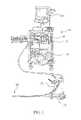
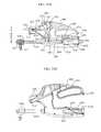
- FIG. 1is an illustrative view showing an endoscopic suturing system with endoscope system according to a first embodiment of the present invention
- FIG. 2is an enlarged view of the proximal portion of an endoscope and an endoscopic suturing system shown in FIG. 1 ;
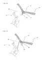
- FIG. 3is a perspective enlarged view of the distal end of an endoscopic suturing system according to an embodiment of the present invention where the actuating arm of the suturing device is closed;
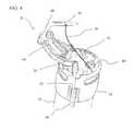
- FIG. 4is a perspective enlarged view of the distal end of an endoscopic suturing system according to an embodiment of the present invention where the actuating arm of the suturing device is open;
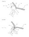
- FIG. 5is another perspective enlarged view of the distal end of an endoscopic suturing system according to an embodiment of the present invention where the actuating arm of the suturing device is open;
- FIG. 6is a perspective enlarged view of the cap assembly of an endoscopic suturing system according to an embodiment of the present invention where the actuating arm of the suturing device is closed;
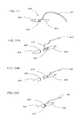
- FIG. 7is an illustrative view of a needle assembly for use with an endoscopic suturing device according to an embodiment of the present invention.
- FIG. 8is an exploded view of a needle assembly of FIG. 7 ;
- FIG. 9is an illustrative view of a needle assembly for use with an endoscopic suturing device according to another embodiment of the present invention.
- FIG. 10is a view of an endoscopic clip for use with an endoscopic suturing system according to an embodiment of the present invention.
- FIG. 11is a view of the preferentially biased resilient endoscopic clip of FIG. 10 when unconstrained.
- FIG. 12is a view of an endoscopic clip for use with an endoscopic suturing system according to another embodiment of the present invention.
- FIG. 13is a view of the preferentially biased resilient endoscopic clip of FIG. 12 when unconstrained
- FIG. 13Ais a view of the preferentially biased resilient modified endoscopic clip of FIG. 13 when unconstrained and having a coil that extends over the sharp tip;
- FIG. 14is a view of the helical tissue grasper
- FIG. 15is an enlarged view of the distal end of the helical tissue grasper
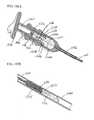
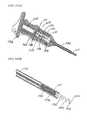
- FIG. 16is a top view of a cinch device and cinch delivery device
- FIG. 17is a side view of a cinch device and cinch delivery device
- FIG. 18is an enlarged exploded view of the distal end of the cinch and cinch delivery device
- FIG. 19is an enlarged view of the cinch device in an open configuration
- FIG. 20is an enlarged view of the cinch device in a closed configuration
- FIG. 21is a sectional view of an endoscopic guide tube
- FIG. 22is a partial sectional view of an endoscopic suturing system disposed within the lumen of an endoscopic guide tube;
- FIG. 23is a partial sectional view of an endoscopic suturing system extending from the distal end of an endoscopic guide tube;
- FIG. 24 through FIG. 34illustrate steps in a surgical suturing procedure using an endoscopic suturing system according to an embodiment of the present invention wherein FIG. 24 is a view of a step in which a an endoscopic suturing device is positioned adjacent a wound at a desired treatment location;
- FIG. 25is a view of a step in which a tissue grasper is extended adjacent a wound at a desired treatment location
- FIG. 26is a view of a step in which a tissue grasper engages tissue and is slightly retracted to bring tissue closer to the endoscope;
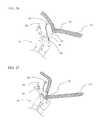
- FIG. 27is a view of an alternative step in which a tissue grasper engages tissue and is substantially retracted to bring tissue in contact with the endoscope;
- FIG. 28is a view of a step in which the needle pierces tissue
- FIG. 29is a view of a step in which the needle holder arm is removed from the tissue depositing a suture through the tissue;
- FIG. 30is a view of a step in which the tissue grasper disengages the tissue
- FIG. 31is a view of a step in which the needle is reloaded into the needle holder arm
- FIG. 32is a view of a step in which a cinch device captures suture
- FIG. 33is a view of a step in which the suture is tightened using the cinch device to thereby close the wound;
- FIG. 34is a view of a cinch device released from the cinch delivery device
- FIG. 35 through FIG. 38illustrate steps in a surgical suturing procedure using an endoscopic suturing system according to another embodiment of the present invention wherein FIG. 35 is a view of a step in which a an endoscopic suturing device has delivered a needle through tissue at a desired treatment location;
- FIG. 36is a view of a step in which a cinch device captures suture
- FIG. 37is a view of a step in which the suture is tightened using the cinch device to thereby close the wound;
- FIG. 38is a view of a cinch device released from the cinch delivery device
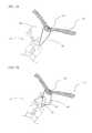
- FIG. 39 through FIG. 42illustrate steps in a surgical suturing procedure using an endoscopic suturing system according to yet another embodiment of the present invention wherein FIG. 39 is a view of a step in which an endoscopic suturing device having a needle clip is positioned at a desired treatment location;
- FIG. 40is a view of a step in which the needle clip pierces tissue
- FIG. 41is a view of a step in which the needle holder arm is removed from the tissue depositing the needle clip through the tissue;
- FIG. 42is a view of a step in which the tissue grasper disengages the tissue and the needle clip close the wound;
- FIG. 43is an illustrative view showing an endoscopic suturing system with a channel lock member according to another embodiment of the present invention.
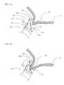
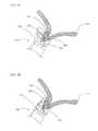
- FIG. 44is a perspective enlarged view of the cap assembly of an endoscopic suturing system according to an embodiment of the present invention where the actuating arm of the suturing device is closed;
- FIG. 45is a perspective enlarged view of the cap assembly of an endoscopic suturing system according to an embodiment of the present invention where the actuating arm of the suturing device is open;
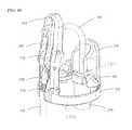
- FIG. 46is a perspective enlarged exploded view of the cap assembly of an endoscopic suturing system according to an embodiment of the present invention.
- FIG. 47is another perspective enlarged view of the cap assembly of an endoscopic suturing system according to an embodiment of the present invention where the actuating arm of the suturing device is closed;
- FIG. 48is yet another perspective enlarged view of the cap assembly of an endoscopic suturing system according to an embodiment of the present invention where the actuating arm of the suturing device is closed;
- FIG. 49is still another perspective enlarged view of the cap assembly of an endoscopic suturing system according to an embodiment of the present invention.
- FIG. 50is still yet another perspective enlarged view of the cap assembly of an endoscopic suturing system according to an embodiment of the present invention.
- FIG. 51is perspective enlarged view of the channel lock tensioner assembly in a first configuration according to an embodiment of the present invention.
- FIG. 52is perspective enlarged view of the channel lock tensioner assembly in a second configuration according to an embodiment of the present invention.
- FIG. 53is an illustrative view of a needle assembly according to an embodiment of the present invention.
- FIGS. 54A through 54Cillustrate steps in assembling the components of a needle assembly according to an embodiment of the present invention
- FIG. 55is an illustrative view of a needle capture device according to an embodiment of the present invention.
- FIGS. 56A and 56Bare enlarged partial section views of the distal end of a needle capture device, where FIG. 56A illustrates the needle capture assembly in a normally closed configuration and FIG. 56B illustrates the needle capture assembly in an open configuration;
- FIG. 57is an enlarged partial section view of the needle capture assembly interlockingly engaging a needle assembly according to an embodiment of the present invention.
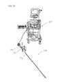
- FIG. 58is a perspective view of a handle assembly of an endoscopic suturing system according to an embodiment of the present invention.
- FIG. 59Ais a cross-sectional view of the handle assembly of FIG. 58 in a closed position with the handle assembly of the capture assembly locked in position therein;
- FIG. 59Bis a perspective view of the arrangement of FIG. 59A ;
- FIG. 59Cis a perspective view of the handle assembly of FIG. 58 in an open position and with the handle assembly of the capture assembly locked in position therein;
- FIG. 60Ais a perspective view of a molded suture dispenser including a removable needle shield tab
- FIG. 60Bis a perspective view of the suture dispenser where the needle shield tab has been removed to provide access to the needle retaining member;
- FIG. 60Cis an exploded perspective view illustrating the components of the molded suture dispenser
- FIG. 61Ais an enlarged perspective view of the needle retaining member
- FIG. 61Bis an enlarged partial cross-sectional view of the needle retaining member securing the removable needle assembly
- FIG. 62Ais a perspective view illustrating the needle capture device engaging the suture dispenser
- FIG. 62Bis an enlarged partial cross-sectional view of the needle capture assembly interlockingly engaging the removable needle assembly positioned within the needle retaining member of the suture dispenser;
- FIG. 63 through FIG. 69illustrate steps in a surgical suturing procedure using an endoscopic suturing system according to another embodiment of the present invention wherein FIG. 63 is a view of a step in which a an endoscopic suturing device is positioned adjacent a wound at a desired treatment location;
- FIG. 64is a view of a step in which a tissue grasper is extended adjacent a wound at a desired treatment location
- FIG. 65is a view of a step in which a tissue grasper engages tissue and is slightly retracted to bring tissue closer to the endoscope;
- FIG. 66is a view of an alternative step in which a tissue grasper engages tissue and is substantially retracted to bring tissue in contact with the endoscope;
- FIG. 67is a view of a step in which the needle partially pierces tissue
- FIG. 68is a view of a step in which the needle completely pierces tissue
- FIG. 69is a view of a step in which the needle holder arm is removed from the tissue depositing a suture through the tissue;
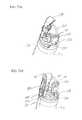
- FIG. 70is an illustrative view showing an endoscopic suturing system with endoscope system according to yet another embodiment of the present invention.
- FIG. 71is an enlarged view of the proximal portion of an endoscope and an endoscopic suturing system shown in FIG. 70 ;
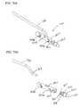
- FIG. 72Ais a perspective enlarged view of the distal end of an endoscopic suturing system according to an embodiment of the present invention where the needle holder arm of the suturing device is closed;
- FIG. 72Bis a perspective enlarged view of the distal end of the endoscopic suturing system in FIG. 72A from another viewing angle;
- FIG. 73Ais a perspective enlarged view of the distal end of an endoscopic suturing system according to an embodiment of the present invention where the needle holder arm of the suturing device is open;
- FIG. 73Bis a perspective enlarged view of the distal end of the endoscopic suturing system in FIG. 73A from another viewing angle;
- FIG. 74is a perspective enlarged view of the cap assembly of an endoscopic suturing system according to an embodiment of the present invention where the actuating arm of the suturing device is closed;
- FIG. 75is a perspective enlarged exploded view of the cap assembly of an endoscopic suturing system according to an embodiment of the present invention.
- FIG. 75Ais a perspective view of an alternate embodiment of an integral tissue guard and mounting portion for the cap assembly of FIG. 75 ;
- FIG. 76Ais an illustrative view of a needle assembly for use with an endoscopic suturing device according to another embodiment of the present invention.
- FIG. 76Bis an exploded view of a needle assembly of FIG. 76A ;
- FIG. 77Ais a partial section view of a needle assembly for use with an endoscopic suturing device according to an embodiment of the present invention.
- FIG. 77Bis a partial section view of a needle assembly for use with an endoscopic suturing device according to an embodiment of the present invention.
- FIG. 78is a partial section view of a needle assembly engaged with a needle holder arm for use with an endoscopic suturing device according to an embodiment of the present invention
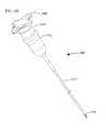
- FIG. 79is an illustrative view of a needle capture device for use with an endoscopic suturing device according to another embodiment of the present invention.
- FIG. 80is a section view of a needle capture device in FIG. 79 for use with an endoscopic suturing device according to another embodiment of the present invention.
- FIG. 81is an enlarged partial section view of a proximal end of a needle capture device for use with an endoscopic suturing device according to another embodiment of the present invention.
- FIG. 82is an enlarged partial section view of a distal end of a needle capture device for use with an endoscopic suturing device according to another embodiment of the present invention.
- FIG. 83Ais an enlarged illustrative view of a distal end of a needle capture device engaged with a needle assembly for use with an endoscopic suturing device according to another embodiment of the present invention
- FIG. 83Bis an enlarged partial section view of a distal end of a needle capture device engaged with a needle assembly for use with an endoscopic suturing device according to another embodiment of the present invention
- FIG. 84is an enlarged partial section view of a distal end of a needle capture device disengaged with a needle assembly for use with an endoscopic suturing device according to another embodiment of the present invention.
- FIG. 85Ais an enlarged illustrative view of a handle bracket for use with an endoscopic suturing device according to another embodiment of the present invention.
- FIG. 85Bis an enlarged illustrative view of an alternative handle bracket for use with an endoscopic suturing device according to another embodiment of the present invention.
- FIG. 86is an illustrative view of a handle assembly for use with an endoscopic suturing device according to another embodiment of the present invention.
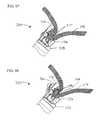
- FIG. 87Ais an illustrative internal view of a handle assembly in an opened position for use with an endoscopic suturing device according to another embodiment of the present invention.
- FIG. 87Bis a partial section view of a handle assembly in FIG. 87A ;
- FIG. 88Ais an illustrative internal view of a handle assembly in a closed position for use with an endoscopic suturing device according to another embodiment of the present invention.
- FIG. 88Bis a partial section view of a handle assembly in FIG. 88A ;
- FIG. 89is a perspective view of a molded suture dispenser including a removable cover
- FIG. 90is an exploded perspective view illustrating the components of the molded suture dispenser
- FIG. 91is a perspective view illustrating the needle capture device engaging the suture dispenser
- FIG. 92 through FIG. 99illustrate steps in a surgical suturing procedure using an endoscopic suturing system according to yet another embodiment of the present invention wherein FIG. 92 is a view of a step in which a an endoscopic suturing device is positioned adjacent a wound at a desired treatment location;
- FIG. 93is a view of a step in which a tissue grasper is extended adjacent a wound at a desired treatment location
- FIG. 94is a view of a step in which a tissue grasper engages tissue and is slightly retracted to bring tissue closer to the endoscope;
- FIG. 95is a view of an alternative step in which a tissue grasper engages tissue and is substantially retracted to bring tissue in contact with the endoscope;
- FIG. 96is a view of a step in which the needle partially pierces tissue
- FIG. 97is a view of a step in which the needle completely pierces tissue
- FIG. 98is a view of a step in which the needle holder arm is partially removed from tissue
- FIG. 99is a view of a step in which the needle holder arm is removed from the tissue depositing a suture through the tissue;
- FIG. 100is a view of a helical tissue grasper according to another embodiment
- FIGS. 101A and 101Bare exploded views of a helical tissue grasper
- FIGS. 102A and 102Bare cross sectional views of the proximal and distal portions of a helical tissue grasper in a first position
- FIGS. 103A and 103Bare cross sectional views of the proximal and distal portions of a helical tissue grasper in a second position
- FIG. 1an endoscope system 10 which comprises an endoscope 12 , a video display unit 14 , an image processing device 16 , a light source 17 , a suction device 18 is used with and an endoscopic suturing device 20 as part of an endoscopic treatment system according to one embodiment of the present invention.
- FIG. 2 and FIG. 3illustrate respectively the proximal and distal portions of endoscope 12 and endoscopic suturing device 20 .
- the endoscopic suturing device 20has an operable handle 22 which is removably coupled to endoscope 12 at a first instrument channel 24 .
- a tissue grasper 26which is used to gather tissue is shown positioned within a second instrument channel 28 of endoscope 12 .
- the endoscopic suturing device 20includes an elongate needle capture device 30 which is removably coupled to handle 22 and extends to the distal end of endoscope 12 slidably positioned within instrument channel 24 .
- the endoscopic suturing device 20is operated by handle 22 which is proximally coupled to transmission assembly 32 which extends distally along the exterior of insertion tube 34 to the distal end 36 of endoscope 12 .
- the transmission assemblyis coupled at its distal end to a cap assembly 38 which is positioned over the distal end 36 of endoscope 12 .
- FIG. 3shows the distal end 40 of needle capture device 30 and the distal end helical tip 42 of tissue grasper 26 extending from instrument channels 24 and 28 respectively.
- Transmission assembly 32comprises an outer sheath 50 which is preferably formed of a flexible coil and a push rod 52 positioned within the lumen and extending from the distal end of outer sheath 50 .
- Outer sheath 50is fixedly secured to cap assembly 38 .
- Push rod 52is coupled to a connecting member 54 via a pivot pin 56 , and optionally via a push member 52 a which may couple the rod 52 and the pivot pin 56 .
- the connecting member 54is also connected to a pair of outer mounting brackets 58 via pivot pin 60 .
- the mounting brackets 58are fixedly attached to cap assembly 38 .
- a pair of inner mounting brackets 62are fixedly attached to the cap assembly 38 and pivotally connected to one end of a link member 64 via pivot pin 66 .
- the other end of link member 64is connected to the needle holder arm 48 via pivot pin 68 .
- Needle holder arm 48is coupled to connecting member 54 via pivot pin 69 .
- FIG. 4the pivotable connections of connecting member 54 and link member 64 to outer and inner mounting brackets 58 and 62 respectively, allow the rotation of needle holder arm 48 when push rod 52 is axially advanced or retracted.
- FIG. 4the cap assembly 38 is shown in an open configuration with push rod 52 advanced (compare FIG. 3 where the cap assembly is in a closed configuration with push rod 52 retracted).
- FIG. 5shows the endoscopic suturing device 20 in an open configuration and from another angle where outer and inner pairs of mounting brackets 58 and 62 are more visible.
- FIG. 6shows a view of cap assembly 38 uncoupled from an endoscope.
- Cap assembly 38includes a fixedly attached insert guide 70 coupled to a flexible channel lock 72 .
- Insert guide 70is a tubular projection from cap assembly 38 and is adapted to be positioned within the lumen of an endoscope instrument channel at its distal end.
- the elongate flexible channel lock 72extends from the insert guide 70 through an instrument channel and is secured to the proximal end of the instrument channel.
- the channel lock 72ensures that the cap assembly 38 does not inadvertently disengage from the distal end of the endoscope.
- channel lock 72takes the form of a small diameter single or multi stranded wire or cable formed primarily of metals or polymers. Additionally the small diameter of channel lock 72 allows room for other instruments to be positioned within the instrument channel of the endoscope.
- FIG. 7illustrates needle assembly 44 which comprises a needle body 74 , a needle tip 76 and suture 46 .
- the suture 46may be formed of any materials commonly available for surgical suture such as nylon, polyolefins, PLA, PGA, stainless steel, nitinol and others.
- FIG. 8shows a detailed exploded view of two components of needle assembly 44 . Needle tip 76 has a sharp distal end and a hollow proximal end having a suture slot 78 through the side wall.
- Needle body 74has a rounded or blunt tapered proximal end 74 a adapted to fit within the needle holder arm with the proximal end 74 a presenting a shoulder 79 between end 74 a and the remainder of the needle body 74 .
- a distal end 74 b of the needle body 74has a suture slot 80 adapted to concentrically engage needle tip 76 .
- Flexible suture materialis positioned on the distal end of needle body 74 extending through the aligned suture slots 78 and 80 .
- the needle tip 76 and needle body 74are formed from suitable biomaterials and may be made from polymers such as nylon, PEEK, PLA, PGA, PLGA or metals such as stainless steel, nitinol or titanium.
- FIG. 9illustrates an alternative needle assembly 82 having a needle tail 84 and a needle tip 86 .
- Needle tip 86has a sharpened distal end, a suture aperture 88 and a hollow proximal end which is adapted to receive needle tail 84 .
- Suture 90is positioned within the hollow end of needle tip 86 and extends through aperture 88 .
- Needle tail 84 and suture 90are secured in the hollow end of needle tip 86 using any of the aforementioned joining techniques.
- Needle tail 84is preferably formed in a straightened shape and of a resilient material such as nitinol. When needle tail 84 is placed in a curved needle holder arm the needle tail bends and applies a force to the inner wall of the needle holder arm maintaining the needle assembly 82 securely in place.
- FIG. 10 through FIG. 13Aillustrate alternate versions of needle assemblies for use in closing tissue defects.
- FIG. 10shows a needle clip 92 in a straightened configuration having a body portion 94 a proximal beaded end 96 and a piercing tip 98 .
- the needle clip 92is preferably formed of nitinol or other resilient material and biased into a generally circular shape. Needle clip 92 may be constrained in a generally straightened configuration but when unconstrained transitions to its biased generally circular configuration as shown in FIG. 11 .
- the needle clip 100shows an alternate needle clip 100 having a proximal bead 102 , a piercing tip 104 , an outer coil covering 106 , and a body portion 108 connecting the proximal and distal ends.
- the needle clip 100also includes a securing member 110 to fixedly attach at least a portion of coil 106 to body portion 108 .
- the needle clip 100is preferably comprised of nitinol or other resilient material and is biased into a generally circular shape. Needle clip 100 may be constrained in a generally straightened configuration but when unconstrained transitions to its biased generally circular configuration as shown in FIG. 13 .
- the coil 106may be formed of suitable biomaterials such as polymers of nylon, polyester, PEEK, PLA, PGA, PLGA or metals such as stainless steel, nitinol, titanium or platinum.
- the coil 106provides increased surface area for tissue in growth and encapsulation as well as distributing the force placed on tissue when closing a tissue defect.
- FIG. 13Ashows a needle clip 100 in which the coil 106 extends over the sharp piercing tip thereby shielding the tip from inadvertent damage to surrounding tissue.
- FIG. 14shows the tissue grasper 26 which has a proximal handle 109 , an elongate shaft member 111 and a helical tip 42 .
- Shaft member 111is formed of a wire or multi-stranded cable or any torque transmitting configuration that provides flexibility which does not impede the steering capabilities of the endoscope.
- FIG. 15shows an enlarged view of the distal end of tissue grasper 26 .
- Shaft member 111is coupled to helical tip 42 by tip coupling member 112 .
- Tip coupling member 112may be fixedly joined to helical tip 42 and shaft member 111 by any of the aforementioned joining techniques.
- FIG. 16 and FIG. 17show a cinch deployment system 114 for securing suture placed at a tissue defect site.
- the cinch deployment system 114comprises a cinch assembly 116 and a cinch delivery device 118 .
- the cinch delivery device 118has an elongate flexible tubular shaft 120 which is removably coupled at its distal end to cinch assembly 116 and fixedly attached at its proximal end to handle member 122 .
- Handle member 122includes a slidable finger ring assembly 124 and a thumb ring 126 . Slidably disposed within the lumen of tubular shaft 120 is push rod 128 .
- Push rod 128extends from the distal end of tubular shaft 120 to the proximal end of tubular shaft 120 and is coupled to the slidable finger ring assembly 124 with fixation screw 130 , such that movement of the finger ring assembly relative to the thumb ring 126 causes the axial movement of push rod 128 within the lumen of tubular shaft 120 .
- a partially exploded view of the distal end of the cinch deployment system 114is shown in FIG. 18 . As depicted, push rod 128 extends from tubular shaft 120 and through latch assembly 129 . Latch assembly 129 is fixedly attached to tubular shaft 120 and has two latch arms 132 with latch tabs 134 at their distal ends.
- Latch arms 132are biased inwardly towards the central longitudinal axis of tubular shaft 120 .
- Latch assembly 129is positioned within the lumen of a latch coupling 136 and is fixedly secured.
- Latch coupling 136is configured at its distal end to engage with the proximal end of cinch 116 such that the latch arms 132 extend within the proximal lumen of cinch 116 and when push rod 128 is positioned within latch assembly 129 the latch arms 132 are forced outwardly such that the latch tabs 134 locking engage the cinch tab apertures 138 .
- FIG. 19illustrates the cinch assembly 116 in an open configuration.
- Cinch assembly 116has a tubular housing member 139 having cinch tab apertures 138 located at its proximal end and a suture hook 140 fixedly attached at its distal end.
- a securing clasp 142is slidably positioned within the lumen of housing member 139 .
- a retention tab 144is preferably formed from the wall of housing member 139 and biased inwardly towards the central axis at of housing member 139 at its distal end.
- the suturemay be secured within cinch assembly 116 by advancing push rod 128 such that securing clasp 142 extends from housing member 139 and engages suture hook 140 .
- retention tab 144moves to its inwardly biased configuration restricting the proximal movement of the securing clasp 142 thereby fixing the suture in place.
- FIG. 21illustrates a guide tube 146 for use in an endoscopic procedure.
- Guide tube 146has a proximal end 148 including a lumen 150 that extends to the distal end 152 .
- a guide tube 146is positioned in a patient to provide a conduit to a desired location while protecting the surrounding tissue from inadvertent damage.
- FIG. 22 and FIG. 23show a guide tube 146 with an endoscopic suturing device 20 positioned in the lumen 150 . Once the guide tube 146 is positioned at a desired treatment location within the body the distal end of the endoscopic suturing device 20 may be extended beyond the distal end of the guide tube 146 .
- FIG. 24 through FIG. 34depicts a method of performing a suturing operation using an endoscopic suturing device 20 of the present invention.
- the endoscopic suturing device 20is positioned adjacent tissue 154 which has a tissue defect 156 to be closed.
- the endoscopic suturing device 20is in an open configuration.
- FIG. 25shows the tissue grasper 26 extended from the endoscope instrument channel such that helical tip 42 is adjacent tissue defect 156 . Rotation of the tissue grasper 26 causes the helical tip 42 to securely engage the tissue 154 adjacent to the tissue defect 156 .
- the tissue 154may be brought closer to the endoscope by slightly retracting the tissue grasper 26 into the instrument channel of the endoscope as shown in FIG. 26 .
- the degree of tissue retractioncorrelates to the size and location of the stitch. For instance, to have a larger amount of tissue sutured, the tissue 154 may be brought into contact with the endoscope by the tissue grasper as shown in FIG. 27 .
- the needle holder arm 48is actuated to move to a closed position causing the needle assembly 44 to pierce tissue 154 .
- the suture 46is pulled through the tissue as shown in FIG. 28 .
- the control over the amount of tissue retractedallows the physician the ability to perform a partial thickness stitch within the wall of a tissue or a full thickness stitch which extends through a wall of tissue.
- the needle capture devicecaptures the needle assembly 44 by gripping it at shoulder 79 ( FIG.
- FIG. 29shows the needle holder arm 48 moved to an open configuration and removed from tissue 154 . Suture 46 remains through the tissue.
- FIG. 30shows the lengthening of the suture 46 through the tissue 154 by refracting the endoscopic suturing device 20 while retaining the needle assembly 44 within the needle capture device.
- FIG. 31shows the needle holder arm 48 moved to a closed configuration and needle assembly 44 reinserted into the needle holder arm 48 by advancing the needle capture device if the physician wishes to make another stitch.
- the needle assembly with suturecan be refracted through the endoscope channel and with both ends of the suture, a knot can be tied and pushed down the endoscope channel to the treatment site to secure the tissue.
- the suturecan be secured using a cinch deployment system. As shown in FIG. 32 a cinch assembly 116 and a cinch delivery device 118 may be used to capture the suture 46 . The suture may be pulled tight to securely close the tissue defect 156 . Once the tissue defect 156 is sufficiently closed the cinch assembly 116 may be moved to a closed configuration, thereby securing the suture 46 as shown in FIG. 33 .
- the cinch delivery device 118can release the cinch assembly 116 as shown in FIG. 34 and the suture 46 may then be cut using any standard cutting means such as scissors. It is contemplated that the cinch assembly may incorporate cutting means after securing the suture.
- FIG. 35 through FIG. 38shows another method of closing a tissue defect and securing the suture.
- FIG. 35shows the endoscopic suturing device 20 having delivered a needle assembly 44 (shown schematically) and suture 46 through tissue 154 adjacent a tissue defect 156 where the needle assembly 44 is resting adjacent the surface of tissue 154 .
- FIG. 36shows a cinch deployment system having a cinch assembly 116 and a cinch delivery device 118 that has grasped a portion of suture 46 . The suture is pulled tight to close the tissue defect 156 while the needle assembly prevents the end of suture 46 from pulling through the tissue 154 .
- the cinch assembly 116may be moved to a closed configuration, thereby securing the suture 46 as shown in FIG. 37 .
- the cinch delivery device 118can release the cinch assembly 116 as shown in FIG. 38 and the suture 46 may then be cut using any standard cutting means such as scissors.
- FIG. 39 through FIG. 42shows still another method securely closing a tissue defect.
- FIG. 39shows an endoscopic suturing device 20 having an open configuration and a needle clip 100 having a proximal bead 102 and a piercing tip 104 positioned in needle holder arm 48 .
- the helical tip 42 of the tissue grasper 26has engaged tissue 154 adjacent to the tissue defect 156 and retracted the tissue towards the endoscope.
- FIG. 40shows the needle holder arm 48 in a closed configuration positioned through the tissue with the piercing tip 104 of needle clip 100 having pierced and exited the tissue.
- FIG. 39shows an endoscopic suturing device 20 having an open configuration and a needle clip 100 having a proximal bead 102 and a piercing tip 104 positioned in needle holder arm 48 .
- the helical tip 42 of the tissue grasper 26has engaged tissue 154 adjacent to the tissue defect 156 and retracted the tissue towards the endoscope.
- FIG. 41shows the needle capture device grasping the piercing tip of the needle clip 100 with the needle holder arm 48 in an open configuration and removed from tissue 154 .
- the proximal bead 102 of needle clip 100is positioned adjacent the tissue site initially pierced by the piercing tip.
- FIG. 42shows the release of tissue 154 from the tissue grasper and the resilient needle clip 100 taking its pre-biased generally circular shape thereby closing the tissue defect 156 .
- the application of a tissue sealant or adhesivemay be used to aid in the closing the tissue defect.
- FIG. 43shows an endoscopic suturing device 320 according to another embodiment of the present invention.
- Endoscopic suturing device 320includes a cap assembly 322 which is adapted to engage with the distal end of an endoscope, an elongate channel lock member 324 which is optionally removable from cap assembly 322 , an outer sheath 326 , an inner sheath 328 and an elongate flexible transmission member 330 . As seen in FIG.
- cap assembly 322further includes a fixedly attached channel lock receiver 332 , an endoscope channel insert guide 334 , an elongate tissue guard 336 , an elongate needle guard 338 which extends distally from the base of the cap assembly and houses the mechanical assembly that provides rotational motion for needle holder arm 340 as shown in FIG. 44 .
- Channel insert guide 334is a tubular projection from cap assembly 322 and is adapted to be positioned within the lumen of an endoscope instrument channel at its distal end.
- the elongate flexible channel lock member 324extends from the channel lock receiver 332 through an instrument channel and is secured at the proximal end of the instrument channel.
- channel lock member 324ensures that the cap assembly 322 does not inadvertently disengage from the distal end of the endoscope.
- channel lock member 324takes the form of a small diameter single or multi stranded wire or cable formed primarily of metals or polymers. Additionally the small diameter of channel lock 324 allows room for other instruments to be positioned within the instrument channel of the endoscope.
- FIGS. 44 and 45respectively show the cap assembly 322 in a needle arm 340 closed configuration and a needle arm open configuration.
- the cap assembly 322has a cap or ring element 322 a having an inner diameter of approximately 13.5 mm, an outer diameter of approximately 14.2 mm, a height of a little over 2 mm, and a portion 322 b having a rim width of between 1 mm and 2 mm.
- the elongate tissue guard 336circumscribes approximately 50.degree. of the ring 322 a on its outside surface 336 a and extends vertically approximately 9 mm over the top of the ring element 322 a at its middle portion.
- the inside surface 336 b of the elongate tissue guard 336is generally semicircular (thereby helping define side walls 336 d ) and defines an approximately 4 mm-5 mm opening which extends above a smaller ring 322 c (see FIG. 48 ) of the cap assembly and above a channel of the endoscope into which the needle capture device (described hereinafter with reference to FIGS. 55-57 ) is to be located.
- This channelmay be the same channel of the endoscope into which the channel insert guide 334 is inserted as described hereinafter.
- the top surface 336 d of the elongate tissue guard 336is angled at an approximately 45.degree. angle. With the provided arrangement, and as discussed hereinafter with reference to FIGS. 63-39 , the tissue guard 336 helps fold tissue for stitching and helps prevent tissue which is drawn into the cap assembly from clogging the endoscope channel and preventing stitching.
- the elongate needle guard 338has a height of between approximately 18 mm and 19 mm, and forms an arched opening between two arms 338 a , 338 b which have outside surface spaced approximately 5 mm apart from each other and inside surfaces spaced approximately 3.7 mm from each other.
- the armsare joined by a top arch 338 c and an optional cross-member (stop) 338 d located below the arch 338 c .
- a gear linkage 342described hereinafter.
- the curved needle holder arm 340is arranged such that when a needle is held in the needle holder arm 340 , in a fully open position, the tip of the needle is preferably located under the arch 338 c and between the arms 338 a , 338 b .
- the holder arm 340can then rotate into a closed position through the arched opening above the gear linkage.
- Each arm 338 a , 338 bhas a width of approximately 0.64 mm and a radial thickness of approximately 2.5 mm.
- FIG. 46shows a detailed exploded view of cap assembly 322 .
- Needle holder arm 340includes a first end 340 a which is adapted to frictionally engage a needle assembly, and a second end 340 b is fixedly secured to needle arm gear link 342 (e.g., in a receiving hole 342 a defined therein).
- needle holder arm 340bends through an arc of approximately 90.degree.
- Gear link 342is mounted between needle guard arms 338 a , 338 b and includes a gear portion 344 which is mounted using pivot pin 345 through mounting hole 346 in gear link 342 to mounting holes (first mounting locations) 347 defined in the housing (arms) of needle guard 338 , and an arm or extension portion 343 .
- Gear portion 344includes lateral gear teeth 344 a .
- push member gear link 348includes gear portion 350 a with lateral gear teeth 350 b which mesh with gear teeth 344 a , and an arm 350 c .
- Gear link 348is mounted using pivot pin 351 through mounting hole 352 to mounting holes (second mounting locations) 353 defined in the housing (arms) of needle guard 338 .
- Gear link 348is also coupled through mounting hole 354 in arm 350 c to push member joint 356 using pivot pin 357 and mounting bracket 358 .
- Push member joint 356is fixedly coupled to transmission member 330 .
- FIGS. 47 and 48show cap assembly 322 assembled where gear portion of gear link 348 intermeshes with gear portion of gear link 342 such that when transmission member 330 is advanced gear link 348 rotates and its gear portion causes the gear portion of gear link 342 to rotate causing needle holder arm 340 to move to a closed position. In the closed position, arm 343 of gear link 342 extends around and above gear link 348 and between cross-member 338 d and arch 338 c . In the open position ( FIG.
- the arm 343 of gear link 342extends radially outward relative to needle guard arms 338 a , 338 b , and the back of the arm 350 c may engage the edge of cross-member 338 d which can act as a stop to gear movement.
- Cap assembly 322may also include a wash deflector 360 as shown in FIG. 48 .
- the wash deflectorredirects fluid from the endoscope to wash the gear mechanism to remove debris.
- the aforementioned componentsare all preferably made from biocompatible metals such as stainless steel and titanium although some high strength polymers may be suitable.
- the vertical positioning of mounting holes 347 and 353 in the needle guard arms 338 a , 338 breduces the profile of cap assembly 322 and facilitates delivery of the endoscopic suturing device 320 to a treatment site.
- FIGS. 49 and 50illustrate views of cap assembly 322 where channel lock member 324 is optionally removably secured in channel lock receiver 332 by channel lock retention member 362 .
- retention member 362is formed of a large bead fixedly secured to the distal end of channel lock member 324 , whereas channel lock receiver 332 defines a groove 333 having a width smaller than the width of the bead.
- the channel lock wire or cable 324can be welded or otherwise fixed to the channel lock receiver 332 or to another part of the cap assembly.
- An additional mechanism to increase the retention of the cap assembly to the distal end of the endoscopeis show in FIG.
- FIGS. 51 and 52show how tension is applied to channel lock member 324 and maintained at the proximal end of the endoscope by using a channel lock tensioner 365 that secures the proximal channel lock retention member 366 secured to the proximal end of the channel lock member.
- the channel lock tensioner 365includes a bayonet lock connector 370 , which couples to the endoscope instrument channel and a spring 372 which supports a tensioner housing 374 coupled to a rotatable tensioning wheel 376 having a tab member 378 .
- the proximal end of channel lock member 324is threaded through tensioner housing 374 and through a valve located at the top of the housing, and is positioned within a tab receptacle 380 .
- the tab receptacle 380secures channel lock retention member 366 to the tensioner wheel 376 .
- the tensioner wheel 376can then be rotated (e.g., clockwise) to apply the appropriate tension on the channel lock member and then locked into place by a locking element (not shown).
- Spring 372is used to compensate, by compressing, for the bending of the endoscope to maintain a constant tension on the channel lock member.
- the springcan be provided on the wheel 376 to spring load the wheel toward a desired position (e.g., the position of FIG. 51 ). As the channel lock member 324 is bent along with the scope through a tortuous path, wheel 376 can rotate against the force of the spring to maintain the desired tension on the channel lock member 324 .
- FIG. 53illustrates needle assembly 400 which comprises suture 402 , a needle tip 404 , a lock gap 405 and a needle body 406 .
- the suture 402may be formed of any materials commonly available for surgical suture such as nylon, polyolefins, PLA, PGA, stainless steel, nitinol and others.
- FIGS. 54A through 54Cshow detailed exploded views of the components of needle assembly 400 .
- Needle tip 404has a sharp distal end and a hollow proximal end with a swage lip 408 .
- Needle body 406has a proximal end adapted to fit within the needle holder arm 340 and a distal end having a suture slot 410 .
- Needle body 406is adapted to concentrically engage needle tip 404 and create lock gap 405 .
- Flexible suture material 402is positioned on the distal end of needle body 406 extending through the suture slot 410 .
- the needle tip 404 and needle body 406are formed from suitable biomaterials and may be made from polymers such as nylon, PEEK, PLA, PGA, PLGA or metals such as stainless steel, nitinol or titanium. The components may be joined using standard joining techniques such as thermal bonding, ultrasonic welding laser welding, adhesives or mechanical crimping.
- FIG. 55illustrates a needle capture device 450 , which includes an elongate catheter or tube 452 having at its distal end a needle capture assembly 454 and at is proximal end a button actuator 456 coupled to handle assembly 458 .
- the needle capture device 450is a 3 mm tool in that the tube 452 and the distal end needle capture assembly 454 are preferably at most 3 mm in diameter.
- the handle assembly 458is preferably adapted to be coupled to the handle assembly operating the needle holder arm of the endoscopic suturing device 320 for ease of use.
- handle assembly 458is provided with a deflecting tooth lock 459 a and a generally rigid tooth 459 b which are arranged to engage with reciprocal cavity and locking element in the handle assembly 600 of the suturing device 320 as discussed below with reference to FIGS. 58 and 59 A- 59 C.
- FIGS. 56A and 56Bshow an enlarged partial cross-sectional view of needle capture assembly 454 and the distal end 460 of tube 452 in closed and open configurations respectively.
- Slidably positioned within the lumen of tube 452is push rod or cable 462 which has a proximal end mechanically coupled to button actuator 456 and a distal end coupled to actuator pin 464 .
- Actuator pin 464is positioned within an angled slot 465 defined in lever arm 466 adjacent fixed pivot pin 468 .
- an interlock feature 470At the distal end of lever arm 466 .
- the distal inner portion of needle capture assembly 454forms needle receptacle 472 .
- Button actuator 456incorporates a spring assembly which places push rod 462 under a tension load thereby causing lever arm 466 to remain in an engaged or closed configuration as shown in FIG. 56A .
- button actuator 456When button actuator 456 is depressed, push rod 462 is advanced, there by causing lever arm 466 and interlock feature 470 to a disengaging or open configuration as shown in FIG. 56B .
- FIG. 57illustrates needle assembly 400 positioned within needle receptacle 472 of needle capture assembly 454 . As shown, needle assembly 400 is secured in place by the interlocking engagement of interlock feature 470 and lock gap 405 . In this configuration needle capture device 450 can be used to deliver the needle through the instrument channel of the endoscope to load the needle assembly into needle holder arm 340 .
- a handle assembly 600 for the endoscopic suturing device 320is seen in FIGS. 58 and 59 A- 59 C.
- the handle assembly 600includes a first stationary handle 604 and a second rotatable handle 608 which is rotatably coupled to stationary handle by pivot axle 612 .
- the rotatable handle 608is spring-biased to the open position seen in FIG. 58 by a spring 614 which sits and is fixed between the handles.
- the stationary handle 604defines a proximal cavity 616 for receiving the handle assembly 458 of the needle capture device 450 .
- Extending from the stationary handle 604is a tube 618 which terminates in a port 620 .
- Port 620includes a fluid valve 622 and a mechanical bayonet lock 624 for coupling to the proximal end of an endoscope. Also extending from the stationary handle is sheath 328 which houses the transmission wire 330 . Second handle 608 defines a fingers grip section 626 , and ratcheted locking element 628 at its proximal end. As described hereinafter, the rotatable second handle 608 is coupled to the transmission wire 330 . Movement of the rotatable handle towards the fixed handle causes axial movement (refraction) of the transmission wire 330 . Movement of the rotatable handle away from the fixed handle causes axial movement (extension) of the transmission wire 330 in an opposite direction.
- FIGS. 59A-59Cadditional details of the handle assembly 600 are seen in addition to how the handle assembly 458 of the needle capture device 450 interacts with the handle assembly 600 of the endoscopic suturing device 320 .
- pivotably coupled to the inside of first handle 604 by pivot pin 632is an actuation pivot element 634 .
- the transmission wire 330is coupled to the actuation pivot element 634 at a second location 636 by a spring 638 which can move in a predetermined distance in a cavity 639 defined by fixed handle 604 .
- the rotatable handle 608is also coupled to the actuation pivot element 634 at a third location 640 by bracket 642 which is coupled to the rotatable handle 608 by post 644 .
- rotation of the handle 608i.e., squeezing
- bracket 642to pull location 640 of the actuation pivot element 634 downward.
- Movement of location 640 downwardis accompanied by clockwise rotation of the actuation pivot element 634 about pivot pin 632 , and thus backward (clockwise) movement of the connection between spring 638 and the actuation pivot element 634 at location 636 . Movement of spring 638 backward pulls transmission wire 330 backward.
- FIG. 59AAlso seen in FIG. 59A is the interaction of handle assembly 600 with the handle assembly 458 of the needle capture device 450 .
- the stationary handle 604is provided with a catch 648 which extends into cavity 616 and is designed to engage the flexible tooth (latch) 459 a of the needle capture device handle assembly 458 .
- cavity 616has a bottom proximal ledge 650 for receiving rigid tooth 459 b .
- Tube 618 which extends out of the stationary handle 604extends into a tubular cavity 654 of the stationary handle 604 which houses a spring 656 , thereby spring loading tube 618 outward.
- the distal end of the needle capture assemblyis threaded into cavity 616 of the stationary handle 604 , tubular cavity 654 , tube 618 , port 620 and then into the endoscope.
- the needle capture assembly 454is pushed through until the handle 458 engages the cavity 616 of the stationary handle 604 .
- rigid tooth 459 baligns with ledge 650
- flexible latch 459 aengages catch 648 , thereby locking the needle capture device 450 in place.
- Cable 462 of the needle capture device 450 with sheath 452extends from the button actuator 457 through the tubular cavity 654 , through the tube 618 , and through and out of the port 620 .
- button 456is pushed as previously described. Disconnection of the needle capture device 450 from the handle assembly 600 is obtained by pressing down on a relieved portion 459 c of the handle 458 adjacent and proximal the latch 459 a , thereby causing the latch to disengage from the catch 648 , and pulling proximally on the handle 458 .
- the needle capture device handle 458is preferably provided with a ratchet locking extension or (hooked) tooth 459 d .
- the handles 604 and 608may be locked into place in a closed position by engaging ratcheted locking element or tooth 628 on rotatable handle 608 with the similar ratcheted locking extension or tooth 459 d of the needle capture assembly 450 (which in turn is locked in stationary handle 604 ) as seen best in FIG. 59C .
- the teeth 628 and 459 dare generally laterally offset, but include hooked portions which after sliding past each other, will engage or grip each other, thereby locking in place. Disengagement is obtained by applying a relative lateral force to one or both of the handles.
- FIG. 60AAn innovative suture dispenser 500 having a dispenser body 502 and a removable needle shield tab 504 is shown in FIG. 60A .
- the suture dispenser 500is shown in FIG. 60B with the needle shield tab 504 removed from the dispenser revealing a needle retaining member 506 .
- FIG. 60Cshows an exploded perspective view of the components.
- Suture dispenser 500includes a lower body 508 and upper body 510 which together form a cavity which houses suture spool 512 containing suture 402 , needle shield 504 and needle retaining member 506 .
- the lower and upper bodies 508 , 510preferably include ribs 508 a , 508 b (similar ribs on upper body not shown) on and about which spool 512 rests so that spool 512 can rotate with a minimum of friction in the cavity.
- the lower and upper bodies 508 , 510are also each preferably provided with walls 513 a , 513 b , 513 c (seen in FIG. 60C only with respect to lower body 508 ) which retain the needle retaining member 506 in place but permit the needle shield tab 504 to be removed. More particularly, wall 513 a is seen to form a back wall for the needle retaining member.
- Wall 513 bis a low wall which is placed in between walls 513 a and 513 c and is connected to the angled portion 513 e of wall 513 a .
- Wall 513 beffectively forms two grooves with the first groove seating the needle retaining member 506 and holding it in place and the second groove seating a portion of the needle shield tab 504 .
- Needle shield tabextends out of a radial opening or orifice in outer wall 513 c and can be pulled out (i.e., can slide out) completely to reveal a receiving cavity 514 in the needle retaining member 506 .
- the outer wall 513 cis also provided with an opening or orifice 513 f in front of the receiving cavity 514 .
- the suture dispenser 500 and most of its componentsare easily fabricated at low cost using suitable polymers, such as polyethylene, polypropylene or polystyrene, injection molding and preferably designs which snap together (e.g., latches 508 c and hollow receiving post 508 d on lower body 508 , and catches 510 c and post (not shown) on upper body 510 ).
- needle shield 504is preferably provided with prongs 504 a .
- the prongsare squeezably held between ribs (not shown) extending from the lower and upper bodies 508 , 510 in order to hold the needle shield 504 in place.
- the prongsare resilient, application of force to the tab portion 504 b of the needle shield 504 , permits the needle shield 504 to be removed from the dispenser body 502 .
- needle retaining member 506includes a needle receiving cavity 514 as shown in FIGS. 61A and 61B where removable needle assembly 400 is held.
- needle body 406is frictionally held within an orifice 514 a defined in the body of retaining member 506 (in much the same manner it is frictionally held in the needle holder arm 340 ( FIG. 46 ) and the needle is connected to suture 402 which is wound on the suture spool.
- Needle tip 404is accessible to the needle capture assembly 454 through needle receiving cavity 514 ; i.e., the cavity provides room around the needle tip to permit the needle capture assembly to enter the cavity and grab the needle. Also as shown in FIG.
- the needle retaining member 506has laterally elongated upper and lower flanges 514 b which are receiving and seat in the grooves formed by the walls 513 a , 513 b of the lower and upper bodies 508 , 510 of the suture dispenser 500 .
- the body of the needle retaining memberhas a cylindrical portion which extends backward through the orifice 513 d of the inner wall 513 a.
- FIGS. 62A and 62Bshow the suture dispenser 500 receiving the needle capture assembly 454 of needle capture device 450 .
- FIG. 62Bshows a partial cross section view of the needle capture assembly 454 interlockingly engaged with the needle for removal from the dispenser.
- FIG. 63 through FIG. 69depicts a method of performing a suturing operation using an endoscopic suturing device 320 of the present invention.
- the endoscopic suturing device 320is positioned adjacent tissue 154 which has a tissue defect 156 to be closed.
- the endoscopic suturing device 320is in an open configuration and the tip of needle assembly 400 is shrouded by needle guard 338 .
- FIG. 64shows the tissue grasper 26 is extended from the endoscope instrument channel such that helical tip 42 is adjacent tissue defect 156 . Rotation of the tissue grasper 26 causes the helical tip 42 to securely engage the tissue 154 adjacent to the tissue defect 156 .
- the tissue 154may be brought closer to the endoscope by slightly retracting the tissue grasper 26 into the instrument channel of the endoscope as shown in FIG. 65 .
- the needle guard 338prevents the tissue from dragging against the tip of needle assembly 400 , thereby reducing inadvertent tissue damage.
- the degree of tissue retractioncorrelates to the size and location of the stitch. For instance to have a larger amount of tissue sutured, the tissue grasper may bring the tissue 154 close to the endoscope as shown in FIG. 66 .
- the position of the angled distal end of tissue guard 336in conjunction with the needle guard 338 , aids in folding the tissue in preparation for suturing and preferably aids in preventing the tissue from locating immediately adjacent and thereby clogging the needle capture device.
- the needle holder arm 340is actuated to move to a closed position causing the needle assembly 400 to pierce tissue 154 .
- the angled portion of tissue guard 336provides support for the tissue allowing the needle to more easily penetrate the tissue as shown in FIG. 67 .
- the suture 402is pulled through the tissue as shown in FIG. 68 .
- the control over the amount of tissue retractedallows the physician the ability to perform a partial thickness stitch within the wall of a tissue or a full thickness stitch which extends through a wall of tissue.
- the needle capture devicecaptures the needle assembly 400 and removes it from the needle holder arm 340 (not shown).
- FIG. 69shows the needle holder arm 340 moved to an open configuration and removed from tissue 154 .
- Suture 402remains through the tissue.
- the needle holder armcan be reloaded with the needle assembly without needing to remove the endoscopic suturing device from the body as previously described. If only one stitch is required the suture may be tied into a surgical knot or a cinch device used to secure the suture, thereby closing the tissue defect.
- FIG. 70illustrates an endoscope system 710 which comprises an endoscope 712 having an insertion tube 714 and an endoscopic suturing device 720 as part of an endoscopic treatment system according to another embodiment of the present invention.
- FIGS. 71 through 72Billustrate respectively the proximal and distal portions of endoscope 712 and endoscopic suturing device 720 .
- the endoscopic suturing device 720has an operable handle 722 which is removably coupled to endoscope 712 at the instrument channel housing 723 by handle bracket 724 with a movable joint 726 .
- Instrument channel housing 723 of endoscope 712allows access to first and second instrument channels 728 and 729 , respectively.
- the endoscopic suturing device 720includes an elongate needle capture device 730 that extends to the distal end of endoscope 712 and slidably positioned within instrument channel 729 .
- the needle capture device 730also includes a handle 731 .
- the endoscopic suturing device 720is operated by handle 722 which is proximally coupled to transmission assembly 732 which extends distally along the exterior of insertion tube 714 to the distal of endoscope 712 .
- the transmission assembly 732is coupled at its distal end to a cap assembly 733 which is positioned over the distal end of endoscope 712 .
- cap assembly 733having a cap base 734 , a lower mounting portion 794 to mount the cap base to the endoscope, a tissue guard 736 , a needle guard 738 , a needle holder arm 740 and a needle assembly 741 .
- the needle holder arm 740is shown in a closed position which places needle assembly 741 partially inside of tissue guard 736 .
- Needle holder arm 740is rotatably coupled to gear assembly 742 and is operated by axial movement of elongated transmission member 744 through transmission catheter 746 of transmission assembly 732 .
- the distal end of transmission catheter 746is fixed to cap base 734 .
- 73A and 73Bshow cap assembly 733 coupled to the distal end of endoscope 712 where needle holder arm 740 is in an open position.
- needle assembly 741which is removably coupled to needle holder arm 740 , is shielded within needle guard 738 and suture 748 is visible extending into instrument channel 729 .
- suture 748is shown extending into instrument channel 729 adjacent the needle capture device distal end 750 .
- FIG. 75illustrates a detailed exploded view of the components of cap assembly 733 .
- Transmission member 744is fixedly coupled to a push member joint 752 having mounting bracket 754 .
- Push member gear link 755having a mounting hole 756 , is pivotably coupled to mounting bracket 754 by securing pivot pin 757 through mounting bracket 754 and mounting hole 756 .
- Push member gear link 755also includes mounting hole 758 and lateral gear teeth 759 .
- Needle holder arm gear link 760includes a mounting hole 762 , adjacent lateral gear teeth 764 , and a needle holder arm mounting hole 766 .
- Needle guard 738is generally formed of two pieces comprising a “U” shaped upper portion 770 , having a wide needle cover 772 and includes a pair of mounting holes 774 (one on each side of the “U”) for additional components and a lower portion 776 that extends the legs of the “U” which is fixedly coupled to both the upper portion 770 and cap base 734 and includes two pair of mounting holes 778 and 780 .
- Needle holder arm gear link 760is secured to lower portion 776 by positioning pivot pin 782 through mounting hole 778 and mounting hole 762 .
- the lateral gear teeth 759 of push member gear link 755are positioned to intermesh with the lateral gear teeth 764 of needle holder arm gear link 760 and the two gear links are secured by positioning pivot pin 784 through mounting hole 780 in lower portion 776 and mounting hole 758 in push member gear link 755 .
- Pin 786is positioned in mounting hole 774 of upper portion 770 and serves to prevent undesirable movement of needle holder arm link 760 .
- Needle holder arm end effector 740is coupled to needle holder arm gear link 760 by fixedly securing needle holder arm end 788 within mounting hole 766 .
- Needle holder arm 740includes a straight tip member 790 adapted to engage needle assembly 741 and defining a longitudinal axis therethrough.
- Tissue guard 736has a generally cylindrical shape and tubular form with a distal or upper portion 792 having a distal surface 792 a obliquely angled relative to a longitudinal axis through the tissue guard, and a suture passage recess 792 b through which suture may extend from within the working channel of the endoscope toward the refracted needle assembly 741 mounted on the needle holder arm 740 ( FIG. 73B ).
- the lower mounting portion 794has a generally cylindrical shape and tubular form that is provided in axial alignment with the tissue guard 736 .
- the tissue guard 736 and lower mounting portion 794are preferably integrally formed from a common tubular member, and an opening extends longitudinally through both the tissue guard 736 and lower mounting portion 794 .
- a proximal portion of the mounting portion 794tapers to a smaller profile in a direction transverse to its longitudinal axis without decreasing the diameter of the opening through the mounting portion to aid in its insertion into the instrument channel 729 , as discussed in more detail below.
- the proximal end of the mounting portion 794has a planar end surface 794 a oriented at an oblique angle relative to the longitudinal axis through the mounting portion 794 (see also FIG. 74 ).
- the proximal portionmay include a surface that taper along a sloped curve to a reduced end cross-sectional profile.
- a base mounting stop 796is located between the upper and lower portions to properly position the guard 736 and mounting portion 794 on the cap base 734 .
- An elongate slot 797 in the wall of tissue guard 736extends from lower mounting portion 794 through base mounting stop 796 and a portion of upper portion 792 .
- the slot 797may be straight, as shown in FIG. 75 , or as shown in the alternative embodiment of FIG. 75A , the slot 797 a may be non-straight, e.g., extending in a zig-zag. Such non-straight extending slot 797 a reduces potential interference with suture extending in proximity to the slot.
- Cap base 734includes a mounting hole 798 in which to position lower mounting portion 794 .
- Base mounting stop 796mates about mounting hole 798 to properly longitudinally portion the tissue guard 736 and the mounting portion 794 and is subsequently fixedly secured, preferably by laser welding.
- Lower mounting portion 794is preferably formed of a resilient material and has an outer diameter which is slightly larger than the diameter of the instrument channel of the endoscope.
- the outwardly biased diameter of lower mounting portion 794may be temporarily compressed or squeezed using a fingers or a tool (not shown) to reduce the diameter for insertion into the instrument channel. Once the compression source is removed the resilient bias of the lower portion 794 outer diameter engages with the inner diameter wall of the instrument channel with sufficient force to retain cap assembly 733 on the distal end of endoscope 712 .
- FIG. 76Aillustrates needle assembly 741 which comprises a preferably straight, hollow needle body 800 , a straight needle tip 802 and suture 748 .
- Needle body 800is preferably formed from a hypotube of suitable biocompatible material. Needle body 800 is preferably processed, by laser cutting, to form various features in the wall of the tube along the length of the tube such as tip tabs 804 a and 804 b located at one end of the tube, suture tabs 806 a and 806 b , needle holder arm tabs 808 a and 808 b at the other end of the tube, as well as, suture hole 809 positioned generally in the middle of the tube.
- FIG. 76Bshows an exploded view of needle assembly 741 to provide further component detail.
- Needle tip 802has a sharp end 810 , a capture groove portion 812 , a tab groove portion 814 , a cap plug portion 816 positioned between the grooves and a blunt end portion 817 .
- blunt end portion 817 of needle tip 802is positioned within the lumen of needle body 800 such that tip tabs 804 a and 804 b are adjacent tip groove portion 814 .
- cap plug portion 816plugs one end of needle body 800 .
- Tip tabs 804 a and 804 bare plastically deformed towards the lumen of needle body 800 to engage tab groove portion 814 thereby providing a mechanical interlock securing needle tip 802 to needle body 800 .
- Suture 748has an end portion 818 that is positioned within needle body 800 through suture hole 809 adjacent blunt end portion 817 .
- Suture tabs 806 a and 806 bare plastically deformed inwardly towards the lumen of needle body 800 to secure suture end 818 within the lumen of needle body 800 .
- Needle holder arm tabs 808 a and 808 bare also plastically deformed towards the lumen of needle body 800 .
- sharp end 810 of needle tip 802has a first taper region 820 and a second taper region 822 .
- FIG. 78illustrates a partial cross sectioned view of tip portion 790 of needle holder arm 740 engaged with needle assembly 741 .
- Tip portion 790having a first, a second and a third portion 824 , 826 and 828 respectively, is positioned within the open end of needle body 800 .
- the diameter of first and third portions 824 , 826are slightly smaller than the inner diameter of needle body 800 while the diameter second portion 826 appreciably smaller to define a circumferential groove 829 between the first and third portions 824 , 828 .
- Needle holder arm tabs 808 a and 808 bflex as first portion 824 enters the lumen of needle body 800 and elastically recover to engage second portion 826 of needle holder arm 740 .
- a noticeable forceis required to cause the flexure of tabs 808 a and 808 b ensuring that needle body 800 does not inadvertently disengage from needle holder arm 740 .
- the force to remove the needle body 800 from the tip portion 790is applied in a direction away from the tip portion and coaxial with the axis of the tip portion.
- other means for attaching the needle body to the needle holder armcan be provided.
- the needle bodymay be provided with a plurality of arms into which the needle holder arm is received.
- FIG. 79depicts needle capture device 730 having an elongate primary catheter 830 that extends from distal end 750 to proximal handle 731 . Also extending from the proximal handle 731 are stiffener sheaths 832 and 834 . Primary catheter 830 may be formed as a coil catheter providing flexibility and some resistance to compression.
- FIG. 80 through FIG. 82illustrate cross section views of needle capture device 730 .
- FIG. 81shows an enlarged cross section of handle 731 .
- Handle 731includes a main body 836 and a button member 838 .
- Main body 836has a cavity 840 that is dimensioned to receive shaft portion 842 of button member 838 .
- a spring member 844is positioned within cavity 840 and couples to button member 838 .
- An elongate cable 846is coupled to shaft 842 and extends through main body 836 coupled to primary catheter 830 to distal end 750 .
- Main body 836includes a flange portion 848
- button member 838includes a primary contact point 850 .
- Flange portion 848is adapted to hold main body 836 by two fingers while primary contact point 850 is adapted to engage a thumb to depress button member 838 .
- the distal end 750 of needle capture device 730includes a capture housing 852 having a proximal end 853 that is coupled to the distal end 854 of primary catheter 830 as illustrated in FIG. 82 .
- the primary catheter 830 and cable 846are sized in length to locate a distal end of the capture housing 852 at the distal end of the instrument channel without protruding therefrom when the needle capture device 730 is fully inserted into the instrument channel 729 of the endoscope.
- outer rigid hypotube 856Within the capture housing there is an outer rigid hypotube 856 , and inner rigid hypotube 858 and an intermediate rigid hypotube 860 .
- Inner hypotube 858is positioned within the lumen of intermediate hypotube 860 which is positioned within the lumen outer hypotube 856 .
- the intermediate hypotube 860has a proximal end 862 that is connected to distal end 864 of cable 846 .
- the proximal end 866 of outer hypotube 856is coupled to distal end 854 of primary catheter 830 , while the outer hypotube distal end 868 is coupled to the distal end 870 of capture housing 852 .
- Outer hypotube 856includes laser cut tab features 872 a and 872 b cut from the wall.
- Intermediate hypotube 860includes elongate laser cut slots 874 .
- Inner hypotube 858also includes laser cut slots 876 .
- Tab features 872 a and 872 bare plastically deformed through slots 874 of intermediate hypotube 860 to engage the slots 876 of inner hypotube 858 , thereby fixedly securing the position of the inner hypotube 858 relative to the outer hypotube 856 but allowing the intermediate hypotube 860 to slide between them for the length of slots 874 .
- Outer hypotube 856has additional laser cut features within the wall that include a live hinge tab 878 that includes a latch tab 880 , and latch release ramp 882 .
- FIG. 83Adepicts an enlarged view of the distal end 750 of needle capture device 730 engaged with needle assembly 741 .
- Capture housing 853includes a plurality of flights 884 separated by space 886 radially arrayed about distal end 870 and a plurality of flights 888 separated by space 890 radially arrayed about proximal end 853 .
- Flights 884 and 888aid in centering distal end 750 within tissue guard 736 to aid in reliably capturing needle assembly 741 from needle holder arm 740 during suturing.
- Spaces 886 and 890 between flightsallow suture within the instrument channel along side needle capture device 730 to be freely dispensed as needed during suturing.
- 83Bis a cross section view of capture housing 852 with needle assembly 741 engaged.
- needle tip 802lifts latch tab 880 .
- latch tab 880returns to its normal inward biased position and engages capture groove portion 812 thereby locking needle assembly 741 within capture housing 852 .
- the strength of this capture engagementis substantially higher than the engagement strength of the needle assembly 741 to needle holder arm 740 , such that rotation of the needle holder arm 740 relative to the engaged needle capture device 730 or refraction of the engaged needle capture device 730 relative to the needle holder arm 740 in a longitudinal direction coaxial with away from the needle coupling tip portion 790 , will exceed the force by which the needle assembly 741 is retained on the needle coupling tip portion 790 causing the needle assembly 741 to disengage from the needle holder arm 740 .
- the distal end 894 of intermediate hypotube 860is positioned proximal to latch release ramp 882 .
- FIG. 84illustrates a needle assembly 741 that has been released from needle capture device 730 .
- cable 846is advanced distally causing the proximal end 862 of intermediate hypotube 860 to move distally relative to outer hypotube 856 .
- latch release ramp 882it causes live hinge tab 878 to raise thereby causing latch tab 880 to be removed from latch groove portion 812 of needle tip 802 .
- FIG. 85Adepicts an embodiments of a handle bracket 724 that includes a molded body portion 895 having sides 896 and 897 .
- a molded flange 898extends around the upper portion of body portion 895 and sides 896 and 897 .
- a molded socket portion 899is positioned at a centered location for coupling with operable handle 722 .
- FIG. 85Billustrates an alternate handle bracket 900 having a molded body portion 902 with sides 904 and 906 and a flange 908 extending around the upper portion of body portion 902 and sides 904 and 906 .
- a molded socket portion 910is positioned at an off center location adjacent to side 904 for coupling with operable handle 722 .
- FIG. 86illustrates a back view of operable handle 722 coupled to handle bracket 900 having a movable joint 726 .
- Handle 722includes a molded main body 912 having a first handle arm 914 , a second handle arm 916 and a cover member 918 .
- FIG. 87Ashows handle 722 without cover member 918 and handle bracket 900 revealing the inner assembly of main body 912 and affixed ball member 920 .
- Spindle member 922is centrally positioned within main body 912 .
- First handle arm 914is integrally formed with plate 923 and transmission member housing 924 and rotatably positioned on spindle member 922 .
- Spring member 926is shown protruding through spring slot 927 in plate 923 .
- Indexer member 928is shown protruding through indexer slot 929 of plate 923 . Movement of indexer member 928 is restricted to positions defined by indexer path 930 which takes the form of a molded guide path in main body 912 .
- FIG. 87Bshows a partial section view of handle 722 revealing the inner portion of transmission member housing 924 .
- Leaf spring member 932has a second arm end 934 positioned adjacent second arm handle 916 and a transmission member end 936 positioned adjacent to transmission member 744 .
- Transmission member 744is fixedly coupled to leaf spring 932 at joint 937 .
- Retaining member 938is coupled to transmission catheter 746 and positioned within transmission member housing 924 of plate 923 .
- indexer path 930includes lock position 944 in which first arm handle 914 may be temporarily locked when closed.
- FIGS. 88A and 88Bshow handle 722 in a closed and locked position.
- First handle arm 914is shown positioned adjacent second handle arm 916 .
- Transmission member housing 924is shown rotated about spindle 922 such that transmission catheter 746 is advanced distally relative to transmission member 744 causing needle holder arm 740 of cap assembly 733 to close. ( FIG.
- Spring member 926is compressed due to the rotation of plate 923 about spindle member 922 . Further compression of first handle arm 914 causes indexer member 928 to move from temporary lock position 944 and follow indexer path 930 to a position where the stored energy of compressed spring member 926 is released to cause the rotation of transmission member housing 924 which retracts transmission catheter 746 relative to transmission member 744 to thereby open needle holder arm 740 of cap assembly 733 .
- FIG. 89illustrates a suture dispenser 950 that includes a molded base member 952 having a generally oval shape, a raised outer wall 953 and a flexible cover member 954 .
- Cover member 954has an access aperture 955 to access needle assembly 741 .
- Cover member 954has a shape and dimensions to be inserted within outer wall 953 and is secured to base member 952 via a plurality of molded tabs 956 attached to outer wall 953 and being projected inwardly in a plane generally parallel to base member 952 .
- FIG. 90shows an exploded view of suture dispenser 950 .
- Molded base member 952also includes a raised inner wall 958 having a plurality of molded winding tabs 960 and 962 attached to inner wall 958 curved sections 961 and 963 extending towards the outer wall 953 in a plane generally parallel to base member 952 . Molded base member 952 further includes a needle housing support member 964 having a needle holding aperture 966 for holding needle assembly 741 . Suture 748 is wound around the inner wall 958 and positioned between winding tabs 960 and 962 and base member 952 with needle assembly 741 being positioned in needle holding aperture 966 .
- FIG. 91illustrates capture housing 852 of the distal end 750 of needle capture device 730 engaging needle assembly 741 through access aperture 955 of suture dispenser 950 .
- FIG. 92 through FIG. 99depicts a method of performing a suturing operation using an endoscopic suturing device 720 of the present invention.
- the endoscopic suturing device 720is positioned adjacent tissue 154 which has a tissue defect 156 to be closed.
- the endoscopic suturing device 720is in an open configuration and the tip of needle assembly 741 is shrouded by needle guard 738 .
- FIG. 93shows the tissue grasper 970 is extended from the endoscope instrument channel such that helical tip 972 is adjacent tissue defect 156 . Rotation of the tissue grasper 970 causes the helical tip 972 to securely engage the tissue 154 adjacent to the tissue defect 156 .
- the tissue 154may be brought closer to the endoscope by slightly refracting the tissue grasper 970 into the instrument channel of the endoscope as shown in FIG. 94 .
- the needle guard 738prevents the tissue from dragging against the tip of needle assembly 741 , thereby reducing inadvertent tissue damage.
- the degree of tissue retractioncorrelates to the size and location of the stitch. For instance to have a larger amount of tissue sutured, the tissue grasper may bring the tissue 154 close to the endoscope as shown in FIG. 95 .
- the position of the angled distal end of tissue guard 736in conjunction with the needle guard 738 , aids in folding the tissue in preparation for suturing and preferably aids in preventing the tissue from locating immediately adjacent and thereby clogging the needle capture device.
- the needle holder arm 740is actuated to move to a closed position causing the needle assembly 741 to pierce tissue 154 .
- the angled portion of tissue guard 736provides support for the tissue allowing the needle to more easily penetrate the tissue as shown in FIG. 96 .
- the suture 748is pulled through the tissue as shown in FIG. 97 .
- the control over the amount of tissue retractedallows the physician the ability to perform a partial thickness stitch within the wall of a tissue or a full thickness stitch which extends through a wall of tissue.
- the needle capture devicecaptures the needle assembly 741 and removes it from the needle holder arm 740 (not shown).
- FIG. 98shows the needle holder arm partially refracted from the tissue illustrating needle holder arm tip 790 contacting tissue.
- FIG. 99shows the needle holder arm 740 moved to an open configuration and removed from tissue 154 . Suture 748 remains through the tissue.
- the needle holder armcan be reloaded with the needle assembly without needing to remove the endoscopic suturing device from the body as previously described. If only one stitch is required the suture may be tied into a surgical knot or a cinch device used to secure the suture, thereby closing the tissue defect.
- FIG. 100illustrates tissue grasping instrument according to another embodiment of the present invention.
- Helical tissue grasper 1000is shown having an elongate catheter 1010 with a handle 1012 positioned at its proximal end.
- Handle 1012has a main body 1014 coupled to catheter 1010 and rotatable knob 1016 for rotating helix member 1018 positioned at the distal end of catheter 1010 .
- FIG. 101Ashows exploded view of the proximal portion of helical tissue grasper 1000 .
- Rotatable knob 1016includes an elongate shaft 1020 , a mounting portion 1022 positioned between extension arms 1024 and 1026 that extend from shaft 1020 . Positioned at the ends of extension arms 1024 and 1026 are engagement tabs 1028 and 1030 respectively.
- Rotatable knob 1016is preferably formed as a molded plastic part with shaft 1020 , mounting portion 1022 , extension arms 1024 and 1026 , engagement tabs 1028 and 1030 , guide members 1032 and 1034 all being integrally formed.
- Guide members 1032 and 1034are spaced apart and extend from their respective extension arm towards the other extension arm.
- Actuation member 1036having proximal end 1037 and angled proximal tip 1038 is shown extending through receiving cavity 1040 of main body 1014 and strain relief member 1042 .
- FIG. 101Bshows an exploded view of the distal portion of helical tissue grasper 1000 .
- Actuation member 1036preferably takes the form of an elongate flexible resilient wire, however, other forms such flexible torque transmitting multi-filament cables, laser cut hypotubes or catheters may also be suitable. Also shown are bearing sleeve 1048 and helix member 1018 having proximal portion 1050 , intermediate portion 1052 , distal portion 1054 and distal tip 1056 . Helix member 1018 preferably takes the form of a coil formed of round wire having a closed pitch at proximal portion 1050 and an expanded pitch at intermediate and distal portions 1052 and 1054 . Distal portion 1054 of helix member 1018 is preferably flattened towards sharpened distal tip 1056 .
- FIGS. 102A and 102Billustrate partial sectioned views of proximal and distal portions of assembled helical tissue grasper 1000 where helix member 1018 is in a delivery configuration.
- Rotatable knob 1016is shown coupled to main body 1014 such that shaft 1022 is inserted into receiving cavity 1040 .
- Engagement tabs 1028 and 1030 of extension arms 1024 and 1026interlockingly engage circular first groove 1058 of main body 1014 .
- Positioned distal to circular first groove 1058 in cavity 1040is circular second groove 1060 .
- Proximal tip 1038 of actuation member 1036is coupled to mounting portion 1022 of shaft 1020 thereby restricting longitudinal movement of actuation member 1036 relative to rotatable knob 1016 .
- Guide members 1032 and 1034are positioned about proximal end 1037 of actuation member 1036 to restrict lateral movement of proximal end 1037 relative to rotatable knob 1016 .
- Actuation member 1036extends through the proximal end of catheter 1010 and strain relief 1042 which are coupled to the distal end of main body 1014 to catheter distal end 1044 .
- Distal end 1046 of actuation member 1036is positioned through the lumen of bearing sleeve 1048 adjacent proximal portion 1050 of helix member 1018 .
- Actuation member distal end 1046is preferably secured to both bearing sleeve 1048 and proximal portion 1050 through laser welding.
- proximal portion 1050 of helix member 1018may be joined directly to bearing sleeve 1048 .
- helix member 1018is fully positioned within the lumen of catheter 1010 at distal end 1044 providing a delivery configuration for helical tissue grasper 1000 .
- sharpened distal tip 1056is shielded by catheter 1010 preventing potential damage to the instrument channel during insertion through the endoscope.
- 103A and 103Billustrate partial sectioned views of proximal and distal portions of assembled helical tissue grasper 1000 where helix member 1018 in a deployed configuration.
- Rotatable knob 1016is advanced distally relative to main body 1014 such that engagement tabs 1028 and 1030 disengage from circular first groove 1058 and interlockingly engage circular second groove 1060 .
- Distal movement of rotatable knob 1016 relative to main body 1014causes actuation member 1036 and helix member 1018 to move distal relative to catheter 1010 such that the intermediate and distal portions 1052 and 1054 and sharpened distal tip 1056 extend distal to catheter distal end 1044 providing a deployed configuration.
- rotation of rotatable knobcauses the rotation of helix member 1018 through the rotation of actuation member 1036 .
- sharpened distal tip 1056is exposed and free to engage tissue.
- each treatment device described abovecan be used together with a rigid endoscope, trocar, or the like as well as flexible endoscopes.
- each treatment device described abovecan be used together with a rigid endoscope, trocar, or the like as well as flexible endoscopes.
- particular sizes and shapeswere described with respect to the end cap, needle guard, tissue guard, etc. of a particular embodiment, other sizes and shapes could be utilized.
Landscapes
- Health & Medical Sciences (AREA)
- Life Sciences & Earth Sciences (AREA)
- Surgery (AREA)
- General Health & Medical Sciences (AREA)
- Veterinary Medicine (AREA)
- Biomedical Technology (AREA)
- Heart & Thoracic Surgery (AREA)
- Medical Informatics (AREA)
- Molecular Biology (AREA)
- Animal Behavior & Ethology (AREA)
- Nuclear Medicine, Radiotherapy & Molecular Imaging (AREA)
- Public Health (AREA)
- Engineering & Computer Science (AREA)
- Physics & Mathematics (AREA)
- Biophysics (AREA)
- Optics & Photonics (AREA)
- Pathology (AREA)
- Radiology & Medical Imaging (AREA)
- Dentistry (AREA)
- Rheumatology (AREA)
- Surgical Instruments (AREA)
- Endoscopes (AREA)
Abstract
Description
Claims (17)
Priority Applications (26)
| Application Number | Priority Date | Filing Date | Title |
|---|---|---|---|
| US13/328,016US8679136B2 (en) | 2008-06-17 | 2011-12-16 | Needle capture device |
| BR122015009792-4ABR122015009792A2 (en) | 2011-05-08 | 2012-05-07 | ENDOSCOPIC SUTURE SYSTEM |
| CN201610075307.7ACN105725954B (en) | 2011-05-08 | 2012-05-07 | Endoscopic Suture System |
| EP21194907.8AEP3939518A3 (en) | 2011-05-08 | 2012-05-07 | Endoscopic suturing system |
| AU2012253729AAU2012253729B2 (en) | 2011-05-08 | 2012-05-07 | Endoscopic suturing system |
| CN201610075304.3ACN105559841B (en) | 2011-05-08 | 2012-05-07 | endoscopic suturing system |
| BR122015008496-2ABR122015008496A2 (en) | 2011-05-08 | 2012-05-07 | ENDOSCOPIC SUTURE SYSTEM |
| EP16190562.5AEP3141193B1 (en) | 2011-05-08 | 2012-05-07 | Endoscopic suturing system |
| CA2985294ACA2985294A1 (en) | 2011-05-08 | 2012-05-07 | Endoscopic suturing system |
| JP2014510391AJP2014519880A (en) | 2011-05-08 | 2012-05-07 | Endoscopic suture system |
| ES16190562TES2896054T3 (en) | 2011-05-08 | 2012-05-07 | Endoscopic Suture System |
| EP12783069.3AEP2706925B1 (en) | 2011-05-08 | 2012-05-07 | Endoscopic suturing system |
| ES12783069.3TES2566379T3 (en) | 2011-05-08 | 2012-05-07 | Endoscopic Suture System |
| EP16150274.5AEP3095391B1 (en) | 2011-05-08 | 2012-05-07 | Endoscopic suturing system |
| CA2985286ACA2985286C (en) | 2011-05-08 | 2012-05-07 | Endoscopic suturing system |
| PCT/US2012/036740WO2012154648A1 (en) | 2011-05-08 | 2012-05-07 | Endoscopic suturing system |
| BR112013028784-5ABR112013028784B1 (en) | 2011-05-08 | 2012-05-07 | NEEDLE SET AND SUTURE YARN |
| CN201280033908.1ACN103813756B (en) | 2011-05-08 | 2012-05-07 | endoscopic suturing system |
| CA2834773ACA2834773C (en) | 2011-05-08 | 2012-05-07 | Endoscopic suturing system |
| KR1020137032468AKR102056038B1 (en) | 2011-05-08 | 2012-05-07 | Endoscopic suturing system |
| KR1020177003916AKR20170020931A (en) | 2011-05-08 | 2012-05-07 | Endoscopic suturing system |
| AU2016213926AAU2016213926B2 (en) | 2011-05-08 | 2016-08-15 | Endoscopic Suturing System |
| JP2016176727AJP6317405B2 (en) | 2011-05-08 | 2016-09-09 | Endoscopic suture system |
| AU2017254809AAU2017254809B2 (en) | 2011-05-08 | 2017-10-30 | Endoscopic Suturing System |
| AU2017254810AAU2017254810B2 (en) | 2011-05-08 | 2017-10-30 | Endoscopic Suturing System |
| JP2017209720AJP6467018B2 (en) | 2011-05-08 | 2017-10-30 | Endoscopic suture system |
Applications Claiming Priority (6)
| Application Number | Priority Date | Filing Date | Title |
|---|---|---|---|
| US7334008P | 2008-06-17 | 2008-06-17 | |
| US16224909P | 2009-03-20 | 2009-03-20 | |
| US12/485,576US8287556B2 (en) | 2008-06-17 | 2009-06-16 | Endoscopic suturing system |
| US201161483679P | 2011-05-08 | 2011-05-08 | |
| US201161495970P | 2011-06-11 | 2011-06-11 | |
| US13/328,016US8679136B2 (en) | 2008-06-17 | 2011-12-16 | Needle capture device |
Related Parent Applications (1)
| Application Number | Title | Priority Date | Filing Date |
|---|---|---|---|
| US12/485,576Continuation-In-PartUS8287556B2 (en) | 2008-06-17 | 2009-06-16 | Endoscopic suturing system |
Publications (2)
| Publication Number | Publication Date |
|---|---|
| US20120149979A1 US20120149979A1 (en) | 2012-06-14 |
| US8679136B2true US8679136B2 (en) | 2014-03-25 |
Family
ID=46200030
Family Applications (4)
| Application Number | Title | Priority Date | Filing Date |
|---|---|---|---|
| US13/327,988Active2033-07-24US9867610B2 (en) | 2008-06-17 | 2011-12-16 | Endoscopic suturing system with retained end cap |
| US13/328,016Active2032-09-05US8679136B2 (en) | 2008-06-17 | 2011-12-16 | Needle capture device |
| US13/328,003Active2031-09-21US9198562B2 (en) | 2008-06-17 | 2011-12-16 | Endoscopic needle assembly |
| US14/924,087Active2029-07-16US11534160B2 (en) | 2008-06-17 | 2015-10-27 | Endoscopic needle assembly |
Family Applications Before (1)
| Application Number | Title | Priority Date | Filing Date |
|---|---|---|---|
| US13/327,988Active2033-07-24US9867610B2 (en) | 2008-06-17 | 2011-12-16 | Endoscopic suturing system with retained end cap |
Family Applications After (2)
| Application Number | Title | Priority Date | Filing Date |
|---|---|---|---|
| US13/328,003Active2031-09-21US9198562B2 (en) | 2008-06-17 | 2011-12-16 | Endoscopic needle assembly |
| US14/924,087Active2029-07-16US11534160B2 (en) | 2008-06-17 | 2015-10-27 | Endoscopic needle assembly |
Country Status (10)
| Country | Link |
|---|---|
| US (4) | US9867610B2 (en) |
| EP (4) | EP2706925B1 (en) |
| JP (3) | JP2014519880A (en) |
| KR (2) | KR102056038B1 (en) |
| CN (3) | CN105725954B (en) |
| AU (6) | AU2012253729B2 (en) |
| BR (3) | BR112013028784B1 (en) |
| CA (3) | CA2985294A1 (en) |
| ES (2) | ES2566379T3 (en) |
| WO (1) | WO2012154648A1 (en) |
Cited By (32)
| Publication number | Priority date | Publication date | Assignee | Title |
|---|---|---|---|---|
| US20150201926A1 (en)* | 2014-01-23 | 2015-07-23 | Lsi Solutions, Inc. | Minimally invasive surgical suturing device and method |
| US20160367240A1 (en)* | 2015-06-17 | 2016-12-22 | Ethicon Endo-Surgery, Llc | Barbed suture dispenser |
| US9554792B1 (en) | 2015-12-15 | 2017-01-31 | Heartstitch, Inc. | Variable spread suturing device |
| WO2017075309A1 (en) | 2015-10-29 | 2017-05-04 | Apollo Endosurgery, Inc. | Endoscopic suture loop anchors and methods |
| WO2018031696A1 (en) | 2016-08-10 | 2018-02-15 | Apollo Endosurgery Us, Inc. | Endoscopic suturing system having external instrument channel |
| US10004491B2 (en)* | 2015-06-15 | 2018-06-26 | Ethicon Llc | Suturing instrument with needle motion indicator |
| US10939909B2 (en) | 2012-12-13 | 2021-03-09 | Ethicon Llc | Circular needle applier with articulating and rotating shaft |
| US11051800B2 (en) | 2016-08-10 | 2021-07-06 | Apollo Endosurgery Us, Inc. | Endoscopic suturing system having external instrument channel |
| US11272918B2 (en)* | 2018-06-27 | 2022-03-15 | Boston Scientific Scimed, Inc. | Endoscope attachment mechanism for use with suture based closure device |
| US11278272B2 (en) | 2018-09-06 | 2022-03-22 | Boston Scientific Scimed, Inc. | Endoscopic suturing needle and suture assembly attachment methods |
| US11298122B2 (en) | 2018-06-07 | 2022-04-12 | EnVision Endoscopy, Inc. | Endoscopic suturing device with circular needle |
| US11304691B2 (en) | 2016-11-13 | 2022-04-19 | Anchora Medical Ltd. | Minimally-invasive tissue suturing device |
| US11375993B2 (en) | 2018-06-19 | 2022-07-05 | Boston Scientific Scimed, Inc. | Endoscopic handle attachment for use with suture based closure device |
| US11534158B2 (en) | 2020-10-23 | 2022-12-27 | EnVision Endoscopy, Inc. | Endoscopic suture cinch |
| US11553909B2 (en) | 2018-05-25 | 2023-01-17 | Boston Scientific Scimed, Inc. | Device and method for applying a cinch to a suture |
| US11744609B2 (en) | 2020-02-19 | 2023-09-05 | Boston Scientific Scimed, Inc. | High power atherectomy with multiple safety limits |
| WO2023183456A1 (en)* | 2021-03-26 | 2023-09-28 | Tsymm Innovations Llc | Suturing device and clamp for use with same |
| US11812944B2 (en) | 2020-02-18 | 2023-11-14 | Boston Scientific Scimed, Inc. | Suture based closure device for use with endoscope |
| US11832809B2 (en) | 2017-02-22 | 2023-12-05 | Boston Scientific Scimed, Inc. | Suture based closure device |
| US11896214B2 (en) | 2020-03-31 | 2024-02-13 | Boston Scientific Scimed, Inc. | Suture based closure device |
| US11918202B2 (en) | 2019-05-16 | 2024-03-05 | Boston Scientific Scimed, Inc. | Suture based closure device for use with endoscope |
| US11986179B2 (en) | 2010-10-01 | 2024-05-21 | Intuitive Surgical Operations, Inc. | Devices and methods for minimally invasive suturing |
| US12070227B2 (en) | 2021-04-07 | 2024-08-27 | Boston Scientific Scimed, Inc. | Medical device including a hemostatis clip |
| WO2024229436A1 (en) | 2023-05-04 | 2024-11-07 | Boston Scientific Scimed, Inc. | Flexible tubular elongate member for medical use, and associated systems and methods |
| WO2024229413A1 (en) | 2023-05-04 | 2024-11-07 | Boston Scientific Scimed, Inc. | Endoscopic system having external instrument channel |
| WO2024229428A1 (en) | 2023-05-04 | 2024-11-07 | Boston Scientific Scimed, Inc. | Devices, systems, and methods for articulation and/or retroflexion of a medical device |
| WO2024229423A1 (en) | 2023-05-04 | 2024-11-07 | Boston Scientific Scimed, Inc. | Devices, systems, and methods for mounting a medical device with respect to another medical device |
| WO2024229441A1 (en) | 2023-05-04 | 2024-11-07 | Boston Scientific Scimed, Inc. | Devices, systems, and methods for performing a procedure with respect to tissue |
| US12171457B2 (en) | 2020-10-30 | 2024-12-24 | Boston Scientific Scimed, Inc. | Atherectomy burrs with blood flow enhancements |
| US12251098B2 (en) | 2021-04-26 | 2025-03-18 | Boston Scientific Scimed, Inc. | Suture based closure device |
| US12376844B2 (en) | 2021-04-26 | 2025-08-05 | Boston Scientific Scimed, Inc. | Suture based closure device |
| US12440205B2 (en) | 2024-01-16 | 2025-10-14 | Boston Scientific Scimed, Inc. | Suture based closure device for use with endoscope |
Families Citing this family (60)
| Publication number | Priority date | Publication date | Assignee | Title |
|---|---|---|---|---|
| US9867610B2 (en) | 2008-06-17 | 2018-01-16 | Apollo Endosurgery Us, Inc. | Endoscopic suturing system with retained end cap |
| US20230181183A1 (en)* | 2008-06-17 | 2023-06-15 | Apollo Endosurgery Us, Inc. | Endoscopic needle assembly |
| WO2009155287A1 (en)* | 2008-06-17 | 2009-12-23 | Apollo Endosurgery, Inc. | Endoscopic suturing system |
| US11812951B2 (en) | 2008-06-17 | 2023-11-14 | Apollo Endosurgery Us, Inc. | Endoscopic needle assembly |
| GB201119897D0 (en)* | 2011-11-18 | 2011-12-28 | Gyrus Medical Ltd | Electrosurgical instrument |
| US10448946B2 (en) | 2013-03-12 | 2019-10-22 | Apollo Endosurgery Us, Inc. | Endoscopic suture cinch |
| WO2014164955A2 (en) | 2013-03-12 | 2014-10-09 | Apollo Endosurgery, Inc. | Endoscopic suture cinch system with replaceable cinch |
| US20150126983A1 (en)* | 2013-11-05 | 2015-05-07 | Apollo Endosurgery, Inc. | Incisionless Endoluminal Gastric Tissue Approximation for the Treatment Of Obesity |
| JP6165083B2 (en)* | 2014-03-04 | 2017-07-19 | オリンパス株式会社 | Medical device cap |
| US9572666B2 (en) | 2014-03-17 | 2017-02-21 | Evalve, Inc. | Mitral valve fixation device removal devices and methods |
| US9859627B2 (en) | 2016-04-26 | 2018-01-02 | Yazaki Corporation | Connection structure of terminal fitting and connection method of terminal fitting |
| US10507038B2 (en)* | 2014-11-12 | 2019-12-17 | Civco Medical Instruments Co., Inc. | Needle guide devices for mounting on imaging transducers or adaptors on imaging transducer, imaging transducers for mounting needle guide devices and adaptors for imaging transducers for mounting needle guide devices thereon |
| US20160287794A1 (en)* | 2015-04-02 | 2016-10-06 | Xend Medical Systems, Llc | Hypodermic needle system activation mechanism |
| US10932948B2 (en)* | 2015-04-20 | 2021-03-02 | Bausch & Lomb Incorporated | Ultrasonic needles and transducer assemblies formed of non-metal materials or a combination of materials |
| GB2543509B (en)* | 2015-10-19 | 2020-10-14 | Creo Medical Ltd | Electrosurgical instrument |
| US12207863B2 (en) | 2015-10-29 | 2025-01-28 | Innoblative Designs, Inc. | Screen sphere tissue ablation devices and methods |
| EP3410949A4 (en)* | 2016-02-05 | 2019-10-09 | Dura Tap LLC | DEVICES AND METHODS FOR SUTURE PLACEMENT |
| CN105640600B (en)* | 2016-03-28 | 2018-03-27 | 王鹏 | Hole clipping stitching devices are stabbed after laparoscopy |
| US10736632B2 (en) | 2016-07-06 | 2020-08-11 | Evalve, Inc. | Methods and devices for valve clip excision |
| JP6538625B2 (en) | 2016-08-29 | 2019-07-03 | 富士フイルム株式会社 | Endoscope and method of assembling the endoscope |
| US10405847B2 (en) | 2016-09-26 | 2019-09-10 | Arthrex, Inc. | Cerclage suture tensioner and methods of tensioning |
| WO2018075389A1 (en) | 2016-10-17 | 2018-04-26 | Innoblative Designs, Inc. | Treatment devices and methods |
| JP6875757B2 (en) | 2016-11-08 | 2021-05-26 | イノブレイティブ デザインズ, インコーポレイテッド | Electrosurgical tissue and vascular seal device |
| CN116158809A (en) | 2016-11-23 | 2023-05-26 | 微仙美国有限公司 | Occlusion removal device and system |
| TR201700324A2 (en) | 2017-01-10 | 2017-07-21 | Alper Celik | ENDOSCOPIC SEWING THREAD |
| CN110099611B (en)* | 2017-01-31 | 2022-03-11 | 日本瑞翁株式会社 | suture device |
| US20180242967A1 (en)* | 2017-02-26 | 2018-08-30 | Endoevolution, Llc | Apparatus and method for minimally invasive suturing |
| US20180256160A1 (en)* | 2017-03-09 | 2018-09-13 | Dura Tap Llc | Loading fixture for a suturing device and method for loading same |
| US10639029B2 (en)* | 2017-06-29 | 2020-05-05 | Ethicon Llc | Suture grasping instrument |
| EP3658053B1 (en) | 2017-07-26 | 2023-09-13 | Innoblative Designs, Inc. | Minimally invasive articulating assembly having ablation capabilities |
| WO2019133439A1 (en)* | 2017-12-29 | 2019-07-04 | The Board Of Regents Of The Unviversity Of Texas | End effector and end effector drive apparatus |
| US11090041B2 (en)* | 2018-01-11 | 2021-08-17 | Apollo Endosurgery Us, Inc. | Device and method for securing endoscope relative to suturing system |
| KR101925744B1 (en) | 2018-02-19 | 2018-12-06 | 이길수 | Medical suture packages |
| WO2020068291A1 (en)* | 2018-09-24 | 2020-04-02 | Boston Scientific Scimed, Inc. | Multiple channel flexible ureteroscope |
| US12102531B2 (en) | 2018-10-22 | 2024-10-01 | Evalve, Inc. | Tissue cutting systems, devices and methods |
| US20210401428A1 (en)* | 2018-10-30 | 2021-12-30 | Health Research, Inc. | Devices and methods for automatic suture |
| US11864751B2 (en)* | 2018-12-05 | 2024-01-09 | Boston Scientific Scimed, Inc. | Endoscopic tissue approximation system and methods |
| WO2020195210A1 (en)* | 2019-03-22 | 2020-10-01 | 株式会社カネカ | Endoscopic treatment instrument |
| US20200337691A1 (en)* | 2019-04-26 | 2020-10-29 | Covidien Lp | Port site incision closure device |
| WO2020236691A1 (en)* | 2019-05-20 | 2020-11-26 | Innoblative Designs, Inc. | Minimally invasive assembly for lung ablation |
| CN110664453B (en)* | 2019-10-24 | 2025-06-10 | 苏州塞洛佩健康科技有限公司 | Tubular tissue stitching device |
| CN114615942B (en)* | 2019-11-05 | 2025-10-03 | 波士顿科学国际有限公司 | Tissue collection spiral device |
| US11547286B2 (en)* | 2020-01-22 | 2023-01-10 | Brio13Inv. LLC | Stylet assembly |
| WO2021183501A1 (en)* | 2020-03-09 | 2021-09-16 | Vanderbilt University | System, apparatus, and method for suturing |
| US12414811B2 (en)* | 2020-05-06 | 2025-09-16 | Evalve, Inc. | Devices and methods for leaflet cutting |
| US12171486B2 (en) | 2020-05-06 | 2024-12-24 | Evalve, Inc. | Devices and methods for clip separation |
| US12171485B2 (en) | 2020-05-06 | 2024-12-24 | Evalve, Inc. | Systems and methods for leaflet cutting using a hook catheter |
| US12048448B2 (en) | 2020-05-06 | 2024-07-30 | Evalve, Inc. | Leaflet grasping and cutting device |
| US12178444B2 (en) | 2020-05-06 | 2024-12-31 | Evalve, Inc. | Clip removal systems and methods |
| DE112022002760T5 (en)* | 2021-05-25 | 2024-03-07 | Gyrus Acmi, Inc. D/B/A Olympus Surgical Technologies America | ELECTRICAL OR MANUAL SEWING DEVICE WITH GEAR |
| EP4346633A4 (en)* | 2021-05-28 | 2025-04-02 | Ergosurgical Group Corp. | Curved suture needle extension |
| ES2947435B2 (en) | 2022-02-07 | 2025-01-03 | Chairmonkey S L | Endoscopic thread suture device |
| JP2023149923A (en)* | 2022-03-31 | 2023-10-16 | 日本ゼオン株式会社 | Endoscope treatment instrument |
| WO2024044131A1 (en)* | 2022-08-22 | 2024-02-29 | Thomas Jefferson University | Device for periurethral bulking and methods incorporating the same |
| CN115429353A (en)* | 2022-08-24 | 2022-12-06 | 武汉拓扑转化医学研究中心有限公司 | Suturing system |
| KR20250097922A (en) | 2022-11-21 | 2025-06-30 | 보스톤 싸이엔티픽 싸이메드 인코포레이티드 | Robotic system for use through natural orifices and suturing within the gastrointestinal tract |
| WO2024178001A1 (en) | 2023-02-21 | 2024-08-29 | Boston Scientific Scimed, Inc. | Robotic surgical system having replaceable suturing tool module |
| WO2025038589A2 (en)* | 2023-08-14 | 2025-02-20 | Intuitive Surgical Operations, Inc. | Endoscopic suturing system utilizing a linear drive needle |
| CN117398141B (en)* | 2023-11-28 | 2024-09-03 | 常州科峰医疗科技有限公司 | Suture instrument for gastroscope and head assembly |
| CN119791746A (en)* | 2025-01-07 | 2025-04-11 | 中南大学湘雅三医院 | Endoscope-assisted needle control and wire-lifting and cutting device |
Citations (196)
| Publication number | Priority date | Publication date | Assignee | Title |
|---|---|---|---|---|
| US3495703A (en) | 1968-04-25 | 1970-02-17 | Smithkline Corp | Suture package |
| US3603492A (en) | 1970-04-13 | 1971-09-07 | John S Schantz | Needle and thread holder |
| US3749328A (en) | 1972-02-07 | 1973-07-31 | J Dusenbery | Apparatus for winding thin film into a roll |
| US3901244A (en) | 1973-05-07 | 1975-08-26 | Edward E Schweizer | Suture cartridge |
| US4084692A (en) | 1974-09-03 | 1978-04-18 | Ethicon, Inc. | Dispenser for surgical threads |
| US4183431A (en) | 1978-06-09 | 1980-01-15 | Sharpoint, Inc. | Access suture package |
| USD263505S (en) | 1979-10-01 | 1982-03-23 | American Cyanamid Company | Dispenser for surgical sutures |
| US4794911A (en) | 1986-09-20 | 1989-01-03 | Olympus Optical Company Ltd. | Means to facilitate detachably mounting cap to distal end of endoscope |
| US5026379A (en) | 1989-12-05 | 1991-06-25 | Inbae Yoon | Multi-functional instruments and stretchable ligating and occluding devices |
| US5041129A (en) | 1990-07-02 | 1991-08-20 | Acufex Microsurgical, Inc. | Slotted suture anchor and method of anchoring a suture |
| US5131534A (en) | 1991-01-07 | 1992-07-21 | United States Surgical Corporation | Suture dispenser |
| US5141520A (en) | 1991-10-29 | 1992-08-25 | Marlowe Goble E | Harpoon suture anchor |
| US5196022A (en) | 1988-12-12 | 1993-03-23 | Ethicon, Inc. | Ligature system for use in endoscopic surgery, ligature and handling instrument for said system |
| US5217486A (en) | 1992-02-18 | 1993-06-08 | Mitek Surgical Products, Inc. | Suture anchor and installation tool |
| US5249671A (en) | 1992-02-07 | 1993-10-05 | United States Surgical Corporation | Package and method of loading for resilient surgical sutures |
| US5263585A (en) | 1992-05-07 | 1993-11-23 | Myriadlase, Inc. | Package for an elongated flexible fiber |
| US5284240A (en) | 1993-01-22 | 1994-02-08 | Ethicon, Inc. | No touch suture package |
| US5304185A (en) | 1992-11-04 | 1994-04-19 | Unisurge, Inc. | Needle holder |
| US5307924A (en) | 1993-03-26 | 1994-05-03 | Abbott Laboratories | Packaging for T-shaped tension devices |
| US5356424A (en) | 1993-02-05 | 1994-10-18 | American Cyanamid Co. | Laparoscopic suturing device |
| US5364408A (en) | 1992-09-04 | 1994-11-15 | Laurus Medical Corporation | Endoscopic suture system |
| US5403328A (en) | 1992-04-22 | 1995-04-04 | United States Surgical Corporation | Surgical apparatus and method for suturing body tissue |
| US5433725A (en) | 1991-12-13 | 1995-07-18 | Unisurge, Inc. | Hand-held surgical device and tools for use therewith, assembly and method |
| US5437266A (en) | 1992-07-02 | 1995-08-01 | Mcpherson; William | Coil screw surgical retractor |
| US5454823A (en) | 1991-09-30 | 1995-10-03 | Richardson; Philip | Suturing apparatus |
| US5464424A (en) | 1994-06-27 | 1995-11-07 | O'donnell, Jr.; Francis E. | Laser adjustable suture |
| US5466241A (en) | 1993-04-23 | 1995-11-14 | Leroy; Joel | Ligature and/or suture system for endoscopic surgery |
| US5470338A (en) | 1993-10-08 | 1995-11-28 | United States Surgical Corporation | Instrument for closing trocar puncture wounds |
| US5474568A (en) | 1993-10-08 | 1995-12-12 | United States Surgical Corporation | Instrument for closing trocar puncture wounds |
| US5478344A (en) | 1993-10-08 | 1995-12-26 | United States Surgical Corporation | Surgical suturing apparatus with loading mechanism |
| US5478345A (en) | 1994-08-19 | 1995-12-26 | United States Surgical Corporation | Mechanism for endoscopic suturing device |
| US5514159A (en) | 1994-09-13 | 1996-05-07 | United States Surgical Corporation | Guillotine suture clip |
| US5520702A (en) | 1994-02-24 | 1996-05-28 | United States Surgical Corporation | Method and apparatus for applying a cinch member to the ends of a suture |
| US5527321A (en) | 1993-07-14 | 1996-06-18 | United States Surgical Corporation | Instrument for closing trocar puncture wounds |
| US5545180A (en) | 1993-12-13 | 1996-08-13 | Ethicon, Inc. | Umbrella-shaped suture anchor device with actuating ring member |
| US5584861A (en) | 1992-09-04 | 1996-12-17 | University College London | Device for use in securing a thread |
| US5584860A (en) | 1995-02-15 | 1996-12-17 | Mitek Surgical Products, Inc. | Suture anchor loader and driver |
| US5601557A (en) | 1982-05-20 | 1997-02-11 | Hayhurst; John O. | Anchoring and manipulating tissue |
| US5626614A (en) | 1995-12-22 | 1997-05-06 | Applied Medical Resources Corporation | T-anchor suturing device and method for using same |
| US5626590A (en) | 1994-02-10 | 1997-05-06 | Wilk; Peter J. | Laparoscopic suturing technique and associated device |
| US5628395A (en) | 1995-06-23 | 1997-05-13 | Ethicon, Inc. | Suture tray package having grooved winding surface |
| US5643320A (en) | 1995-03-13 | 1997-07-01 | Depuy Inc. | Soft tissue anchor and method |
| US5649940A (en) | 1994-09-28 | 1997-07-22 | Innovasive Devices, Inc. | Suture tensioning device |
| US5653717A (en) | 1995-08-28 | 1997-08-05 | Urohealth Systems, Inc. | Wound closure device |
| US5662588A (en) | 1994-05-31 | 1997-09-02 | Olympus Optical Co., Ltd. | Endoscope apparatus |
| US5662658A (en) | 1996-01-19 | 1997-09-02 | Mitek Surgical Products, Inc. | Bone anchor inserter, method for loading same, method for holding and delivering a bone anchor, and method for inserting a bone anchor in a bone |
| US5669917A (en) | 1994-02-24 | 1997-09-23 | Lasersurge, Inc. | Surgical crimping device and method of use |
| US5681331A (en) | 1993-06-02 | 1997-10-28 | De La Torre; Roger A. | Surgical instrument for tying a knot in a length of suture at a remote location |
| US5685823A (en) | 1994-03-30 | 1997-11-11 | Asahi Kogaku Kogyo Kabushiki Kaisha | End structure of endoscope |
| US5707379A (en) | 1995-10-20 | 1998-01-13 | Coral Medical | Method and apparatus for intracorporeal suturing |
| US5713910A (en) | 1992-09-04 | 1998-02-03 | Laurus Medical Corporation | Needle guidance system for endoscopic suture device |
| US5720766A (en) | 1994-02-23 | 1998-02-24 | Orthopaedic Biosystems Limited, Inc. | Apparatus for attaching soft tissue to bone |
| US5733293A (en) | 1996-05-08 | 1998-03-31 | United States Surgical Corporation | Disposable loading unit for a vascular suturing instrument |
| US5755729A (en) | 1995-04-27 | 1998-05-26 | General Surgical Innovations, Inc. | Magazine for loading a needle and a length of suture onto a surgical instrument |
| US5765740A (en) | 1993-12-30 | 1998-06-16 | Ferguson; Patrick J. | Suture-material-dispenser system for suture material |
| US5782862A (en) | 1996-07-01 | 1998-07-21 | Bonutti; Peter M. | Suture anchor inserter assembly and method |
| US5792152A (en) | 1993-11-08 | 1998-08-11 | Perclose, Inc. | Device and method for suturing of internal puncture sites |
| US5792153A (en) | 1994-03-23 | 1998-08-11 | University College London | Sewing device |
| US5810848A (en) | 1996-08-21 | 1998-09-22 | Hayhurst; John O. | Suturing system |
| US5814071A (en) | 1994-11-10 | 1998-09-29 | Innovasive Devices, Inc. | Suture anchor assembly and methods |
| US5814054A (en) | 1996-09-23 | 1998-09-29 | Symbiosis Corporation | Automatic needle-passer suturing instrument |
| US5817013A (en) | 1996-03-19 | 1998-10-06 | Enable Medical Corporation | Method and apparatus for the minimally invasive harvesting of a saphenous vein and the like |
| US5819918A (en) | 1993-09-13 | 1998-10-13 | United States Surgical Corporation | Retainer package for resilient filaments |
| US5824009A (en) | 1995-12-06 | 1998-10-20 | Kabushiki Kaisha Matsutani Seisakusho | Guide instrument for a medical needle with thread |
| US5833055A (en) | 1996-03-29 | 1998-11-10 | Ethicon, Inc. | Surgical suture package with peelable foil heat seal |
| US5843099A (en) | 1997-01-16 | 1998-12-01 | Bei Medical Systems, Inc. | Single system ligature carrier and tissue clamp for sacrospinous colpopexy |
| US5860992A (en) | 1996-01-31 | 1999-01-19 | Heartport, Inc. | Endoscopic suturing devices and methods |
| US5879371A (en) | 1997-01-09 | 1999-03-09 | Elective Vascular Interventions, Inc. | Ferruled loop surgical fasteners, instruments, and methods for minimally invasive vascular and endoscopic surgery |
| US5887594A (en) | 1997-09-22 | 1999-03-30 | Beth Israel Deaconess Medical Center Inc. | Methods and devices for gastroesophageal reflux reduction |
| US5891160A (en) | 1996-02-23 | 1999-04-06 | Cardiovascular Technologies, Llc | Fastener delivery and deployment mechanism and method for placing the fastener in minimally invasive surgery |
| US5897563A (en) | 1997-10-08 | 1999-04-27 | Ethicon Endo-Surgery, Inc. | Method for using a needle holder to assist in suturing |
| US5897564A (en) | 1997-04-08 | 1999-04-27 | Ethicon Endo-Surgery, Inc. | Endoscopic instrument assembly for fastening tissue |
| US5910105A (en) | 1997-04-14 | 1999-06-08 | C.R. Bard, Inc. | Control handle for an endoscope |
| US5918733A (en) | 1998-04-08 | 1999-07-06 | Ethicon, Inc. | Ligating reel package |
| US5944739A (en) | 1998-03-12 | 1999-08-31 | Surgical Dynamics, Inc. | Suture anchor installation system |
| US5947982A (en) | 1997-04-02 | 1999-09-07 | Smith & Nephew, Inc. | Suture-passing forceps |
| US5951587A (en) | 1997-10-09 | 1999-09-14 | Ethicon-Endo-Surgery, Inc. | Needle holder with suture filament grasping abilities |
| US5954731A (en) | 1997-07-29 | 1999-09-21 | Yoon; Inbae | Surgical instrument with multiple rotatably mounted spreadable end effectors |
| US5954733A (en) | 1996-11-27 | 1999-09-21 | Yoon; Inbae | Suturing instrument with rotatably mounted needle driver and catcher |
| US5954732A (en) | 1997-09-10 | 1999-09-21 | Hart; Charles C. | Suturing apparatus and method |
| US5964764A (en) | 1998-03-24 | 1999-10-12 | Hugh S. West, Jr. | Apparatus and methods for mounting a ligament graft to a bone |
| US5993467A (en) | 1996-11-27 | 1999-11-30 | Yoon; Inbae | Suturing instrument with rotatably mounted spreadable needle holder |
| US5993466A (en) | 1997-06-17 | 1999-11-30 | Yoon; Inbae | Suturing instrument with multiple rotatably mounted spreadable needle holders |
| US6010525A (en) | 1997-08-01 | 2000-01-04 | Peter M. Bonutti | Method and apparatus for securing a suture |
| US6036699A (en) | 1992-12-10 | 2000-03-14 | Perclose, Inc. | Device and method for suturing tissue |
| US6048351A (en) | 1992-09-04 | 2000-04-11 | Scimed Life Systems, Inc. | Transvaginal suturing system |
| US6053935A (en) | 1996-11-08 | 2000-04-25 | Boston Scientific Corporation | Transvaginal anchor implantation device |
| US6068648A (en) | 1998-01-26 | 2000-05-30 | Orthodyne, Inc. | Tissue anchoring system and method |
| US6071289A (en) | 1999-03-15 | 2000-06-06 | Ethicon Endo-Surgery, Inc. | Surgical device for suturing tissue |
| US6071233A (en) | 1997-10-31 | 2000-06-06 | Olympus Optical Co., Ltd. | Endoscope |
| US6077286A (en) | 1996-05-07 | 2000-06-20 | Karl Storz Gmbh & Co. Kg | Instrument with a bendable handle |
| US6086608A (en) | 1996-02-22 | 2000-07-11 | Smith & Nephew, Inc. | Suture collet |
| US6086600A (en) | 1997-11-03 | 2000-07-11 | Symbiosis Corporation | Flexible endoscopic surgical instrument for invagination and fundoplication |
| US6086601A (en) | 1998-04-29 | 2000-07-11 | Yoon; Inbae | Instrument and method for suturing anatomical tissue and tying suture material |
| US6096051A (en) | 1998-03-20 | 2000-08-01 | Scimed Life Systems, Inc. | Endoscopic suture systems |
| US6095323A (en) | 1998-06-12 | 2000-08-01 | Ferguson; Patrick J. | Suture-material-dispenser system for suture material |
| US6117144A (en) | 1995-08-24 | 2000-09-12 | Sutura, Inc. | Suturing device and method for sealing an opening in a blood vessel or other biological structure |
| US6126666A (en) | 1997-04-14 | 2000-10-03 | Forschungszcutrum Karlsruhe Gmbh | Device for inserting a surgical suture needle into an endoscopic suture apparatus |
| US6135385A (en) | 1997-10-09 | 2000-10-24 | B. Braun Surgical, S.A. | Suture material dispenser |
| US6136010A (en) | 1999-03-04 | 2000-10-24 | Perclose, Inc. | Articulating suturing device and method |
| US6149658A (en) | 1997-01-09 | 2000-11-21 | Coalescent Surgical, Inc. | Sutured staple surgical fasteners, instruments and methods for minimally invasive vascular and endoscopic surgery |
| USRE36974E (en) | 1993-05-14 | 2000-11-28 | Bonutti; Peter M. | Suture anchor |
| US6159234A (en) | 1997-08-01 | 2000-12-12 | Peter M. Bonutti | Method and apparatus for securing a suture |
| US6171316B1 (en) | 1997-10-10 | 2001-01-09 | Origin Medsystems, Inc. | Endoscopic surgical instrument for rotational manipulation |
| US6224614B1 (en) | 1998-06-17 | 2001-05-01 | Inbae Yoon | Suturing instrument with angled needle holder and method for use thereof |
| US6277064B1 (en) | 1997-12-30 | 2001-08-21 | Inbae Yoon | Surgical instrument with rotatably mounted offset endoscope |
| US6277132B1 (en) | 1997-10-24 | 2001-08-21 | Forschungszentrum Karlsruhe, Gmbh | Needle inserter with a needle protection device |
| US6293961B2 (en) | 1998-12-30 | 2001-09-25 | Ethicon, Inc. | Suture locking device |
| US6306081B1 (en) | 1998-04-21 | 2001-10-23 | Olympus Optical Co., Ltd. | Hood for an endoscope |
| US6312448B1 (en) | 1996-11-15 | 2001-11-06 | Peter M. Bonutti | Apparatus and method for use in positioning an anchor |
| US6352503B1 (en) | 1998-07-17 | 2002-03-05 | Olympus Optical Co., Ltd. | Endoscopic surgery apparatus |
| US6358259B1 (en) | 1992-09-04 | 2002-03-19 | University College London | Device for use in tying knots |
| US20020040227A1 (en) | 1999-06-04 | 2002-04-04 | Boaz Harari | Bone suturing device |
| US20020087190A1 (en) | 1999-02-02 | 2002-07-04 | Benavitz William C. | Insert molded push-in suture anchor |
| US6443962B1 (en) | 1997-09-11 | 2002-09-03 | Benny Gaber | Stitching tool |
| US6467612B1 (en) | 1999-05-24 | 2002-10-22 | David Rosenfeld | Suture reel dispenser with end of suture indicator |
| US6475230B1 (en) | 1997-08-01 | 2002-11-05 | Peter M. Bonutti | Method and apparatus for securing a suture |
| US6533796B1 (en) | 2000-10-11 | 2003-03-18 | Lsi Solutions, Inc. | Loader for surgical suturing instrument |
| US6569085B2 (en) | 2001-08-16 | 2003-05-27 | Syntheon, Llc | Methods and apparatus for delivering a medical instrument over an endoscope while the endoscope is in a body lumen |
| US6585744B1 (en) | 1998-08-19 | 2003-07-01 | Griffith Textile Machines, Ltd. | Surgical sewing device |
| US6596001B2 (en) | 2000-05-01 | 2003-07-22 | Ethicon, Inc. | Aiming device for surgical instrument and method for use for treating female urinary incontinence |
| US20030181924A1 (en) | 2002-01-30 | 2003-09-25 | Olympus Optical Co., Ltd. | Endoscopic suturing system |
| US6635073B2 (en) | 2000-05-03 | 2003-10-21 | Peter M. Bonutti | Method of securing body tissue |
| US6656182B1 (en) | 1982-05-20 | 2003-12-02 | John O. Hayhurst | Tissue manipulation |
| US6663643B2 (en) | 2000-03-27 | 2003-12-16 | Onux Medical, Inc. | Surgical suturing instrument and method of use |
| US6663639B1 (en) | 1999-06-22 | 2003-12-16 | Ndo Surgical, Inc. | Methods and devices for tissue reconfiguration |
| US6695852B2 (en) | 2001-10-31 | 2004-02-24 | Spineology, Inc. | Tension tools for tension band clip |
| US6699183B1 (en) | 1998-09-08 | 2004-03-02 | Xion Gmbh | Quick-acting closure for an endoscope |
| US6719763B2 (en) | 2000-09-29 | 2004-04-13 | Olympus Optical Co., Ltd. | Endoscopic suturing device |
| US6719764B1 (en) | 2001-08-24 | 2004-04-13 | Scimed Life Systems, Inc. | Forward deploying suturing device and methods of use |
| US6733509B2 (en) | 2000-08-25 | 2004-05-11 | Sutura, Inc. | Suture cutter |
| US6740030B2 (en) | 2002-01-04 | 2004-05-25 | Vision Sciences, Inc. | Endoscope assemblies having working channels with reduced bending and stretching resistance |
| US6755843B2 (en) | 2000-09-29 | 2004-06-29 | Olympus Optical Co., Ltd. | Endoscopic suturing device |
| US6804937B2 (en) | 2003-03-13 | 2004-10-19 | Ethicon, Inc. | Package winding machine |
| US6808491B2 (en) | 2001-05-21 | 2004-10-26 | Syntheon, Llc | Methods and apparatus for on-endoscope instruments having end effectors and combinations of on-endoscope and through-endoscope instruments |
| US6866673B2 (en) | 2002-12-20 | 2005-03-15 | Ran Oren | Suture manipulating and/or cutting implement |
| US20050065401A1 (en) | 2003-01-15 | 2005-03-24 | Usgi Medical Inc. | Endoluminal tool deployment system |
| US6893393B2 (en) | 2003-02-19 | 2005-05-17 | Boston Scientific Scimed., Inc. | Guidewire locking device and method |
| US6896686B2 (en) | 2001-03-23 | 2005-05-24 | Arthrex, Inc. | Arthroscopic suture passing instrument |
| US20050149067A1 (en) | 2002-01-30 | 2005-07-07 | Olympus Corporation | Endoscopic suturing system |
| US6921361B2 (en) | 2000-07-24 | 2005-07-26 | Olympus Corporation | Endoscopic instrument for forming an artificial valve |
| US6921408B2 (en) | 2002-03-12 | 2005-07-26 | Lsi Solutions, Inc. | Apparatus for sewing tissue and method of use |
| US6923819B2 (en) | 2001-06-14 | 2005-08-02 | Suturtek Incorporated | Apparatus and method for surgical suturing with thread management |
| US6955643B2 (en) | 2002-06-12 | 2005-10-18 | Boston Scientific Scimed, Inc. | Endoscopic suture instrument |
| US6966916B2 (en) | 2002-09-26 | 2005-11-22 | Kumar Sarbjeet S | Device and method for surgical repair of abdominal wall hernias |
| US6988987B2 (en) | 2002-03-18 | 2006-01-24 | Olympus Corporation | Guide tube |
| US6997931B2 (en) | 2001-02-02 | 2006-02-14 | Lsi Solutions, Inc. | System for endoscopic suturing |
| US7033370B2 (en) | 1992-09-04 | 2006-04-25 | Boston Scientific Scimed, Inc. | Suturing instruments and methods of use |
| US7033379B2 (en) | 2001-06-08 | 2006-04-25 | Incisive Surgical, Inc. | Suture lock having non-through bore capture zone |
| US7041111B2 (en) | 2002-08-02 | 2006-05-09 | Boston Scientific Scimed, Inc. | Placing sutures |
| US7060025B2 (en) | 2002-03-15 | 2006-06-13 | Ethicon Endo-Surgery, Inc. | Method for controlling position of medical instruments |
| US7063710B2 (en) | 2002-04-15 | 2006-06-20 | Nipro Corporation | Intracardiac suture device |
| US7083630B2 (en) | 2002-08-29 | 2006-08-01 | Scimed Life Systems, Inc. | Devices and methods for fastening tissue layers |
| US7083638B2 (en) | 2001-02-12 | 2006-08-01 | Arthrocare Corporation | Method and apparatus for attaching connective tissues to bone using a knotless suture anchoring device |
| US7087012B2 (en) | 2002-02-28 | 2006-08-08 | Olympus Corporation | Endoscope hood |
| US7090686B2 (en) | 1995-08-24 | 2006-08-15 | Sutura, Inc. | Suturing device and method |
| US7090690B2 (en) | 2002-11-19 | 2006-08-15 | Arthrocare Corporation | Devices and methods for repairing soft tissue |
| US7094246B2 (en) | 2001-12-07 | 2006-08-22 | Abbott Laboratories | Suture trimmer |
| US7131979B2 (en) | 2002-05-17 | 2006-11-07 | Dvl Acquisition Sub, Inc. | Surgical suturing instrument and method of use |
| US7144401B2 (en) | 2001-06-07 | 2006-12-05 | Olympus Optical Co., Ltd. | Suturing device for endoscope |
| US20060281970A1 (en) | 2005-06-13 | 2006-12-14 | Stokes Michael J | Attachment apparatus for coupling with an endoscope |
| US7150757B2 (en) | 2003-06-11 | 2006-12-19 | Fallin T Wade | Adjustable line locks and methods |
| US7153314B2 (en) | 1999-06-22 | 2006-12-26 | Ndo Surgical | Tissue reconfiguration |
| US7175636B2 (en) | 2001-08-31 | 2007-02-13 | Tetsuya Yamamoto | Endoscopic suturing instrument |
| US7179277B2 (en) | 2002-07-17 | 2007-02-20 | Tyco Healthcare Group Lp | Surgical needle |
| US7191900B2 (en) | 2003-06-03 | 2007-03-20 | Js Vascular, Inc. | Guide wire containment and dispensing apparatus |
| US7198599B2 (en) | 2002-05-29 | 2007-04-03 | Olympus Corporation | Endoscope apparatus |
| US7204802B2 (en) | 2002-08-29 | 2007-04-17 | Universite De Liege | Surgical procedure for the treatment of female urinary incontinence: tension-free inside-out transobturator urethral suspension |
| US7220266B2 (en) | 2000-05-19 | 2007-05-22 | C. R. Bard, Inc. | Tissue capturing and suturing device and method |
| US7223230B2 (en) | 2002-09-06 | 2007-05-29 | C. R. Bard, Inc. | External endoscopic accessory control system |
| US7235086B2 (en) | 2001-02-02 | 2007-06-26 | Lsi Solutions, Inc. | Crimping instrument with motion limiting feature |
| US7264624B2 (en) | 1997-09-04 | 2007-09-04 | Kensey Nash Corporation | Surgical connector systems and methods of use |
| US7322161B2 (en) | 2005-03-11 | 2008-01-29 | Tyco Healthcare Group Lp | Suture winding device and methods of use thereof |
| US7326221B2 (en) | 2004-04-07 | 2008-02-05 | Olympus Corporation | Ligature and suture device for medical application, and ligaturing and suturing method for medical application |
| US20080039255A1 (en) | 2006-08-08 | 2008-02-14 | Terumo Kabushiki Kaisha | Working mechanism and manipulator |
| US7338504B2 (en) | 2002-10-03 | 2008-03-04 | Gibbens Group, L.L.C. | Cycling suturing and knot-tying device |
| US7344545B2 (en) | 2002-01-30 | 2008-03-18 | Olympus Corporation | Endoscopic suturing system |
| US7371215B2 (en) | 2001-05-01 | 2008-05-13 | Intrapace, Inc. | Endoscopic instrument for engaging a device |
| US7431694B2 (en) | 2003-05-16 | 2008-10-07 | Ethicon Endo-Surgery, Inc. | Method of guiding medical devices |
| US7527590B2 (en) | 2002-03-19 | 2009-05-05 | Olympus Corporation | Anastomosis system |
| US7566300B2 (en) | 2004-04-15 | 2009-07-28 | Wilson-Cook Medical, Inc. | Endoscopic surgical access devices and methods of articulating an external accessory channel |
| US7575548B2 (en) | 2004-09-24 | 2009-08-18 | Olympus Corporation | Endoscopic treatment instrument, endoscopic treatment system and supporting adaptor |
| US7601161B1 (en) | 1999-07-02 | 2009-10-13 | Quick Pass, Inc. | Suturing device |
| US20090312775A1 (en) | 2008-06-17 | 2009-12-17 | Gilkey J Landon | Endoscopic Suturing System |
| US7637369B2 (en) | 2003-07-18 | 2009-12-29 | Tyco Healthcare Group Lp | Suture packaging |
| US7665279B2 (en) | 2005-03-11 | 2010-02-23 | Tyco Healthcare Group Lp | Suture winding device and methods of use thereof |
| US7703459B2 (en) | 2004-03-09 | 2010-04-27 | Usgi Medical, Inc. | Apparatus and methods for mapping out endoluminal gastrointestinal surgery |
| US7727144B2 (en) | 2004-01-16 | 2010-06-01 | Olympus Corporation | Endoscopic surgical instrument |
| US7766162B2 (en) | 2006-01-10 | 2010-08-03 | Cimatex Ab | Receptacle for a catheter |
| US7776066B2 (en) | 2002-07-11 | 2010-08-17 | Olympus Corporation | Endoscopic suture apparatus |
| US7775973B2 (en) | 2005-08-24 | 2010-08-17 | Olympus Medical Systems Corp. | Endoscope system |
| US7785348B2 (en) | 2004-05-14 | 2010-08-31 | Ethicon Endo-Surgery, Inc. | Devices and methods of locking and cutting a suture in a medical procedure |
| US7918867B2 (en) | 2001-12-07 | 2011-04-05 | Abbott Laboratories | Suture trimmer |
| US7931661B2 (en) | 2004-06-14 | 2011-04-26 | Usgi Medical, Inc. | Apparatus and methods for performing transluminal gastrointestinal procedures |
| US7935128B2 (en) | 2003-05-21 | 2011-05-03 | Boston Scientific Scimed, Inc. | Remotely-reloadable suturing device |
| US7988656B2 (en) | 2006-01-13 | 2011-08-02 | Olympus Medical Systems Corp. | Natural orifice medical operation and endoscopic overtube |
Family Cites Families (46)
| Publication number | Priority date | Publication date | Assignee | Title |
|---|---|---|---|---|
| US2023807A (en)* | 1933-03-13 | 1935-12-10 | Francis J Gruss | Surgical needle |
| US3001522A (en)* | 1957-12-26 | 1961-09-26 | Silverman Irving | Biopsy device |
| US3592196A (en)* | 1969-11-28 | 1971-07-13 | Boris Yakovlevich Daikhovsky | Surgical needle with suture retaining means |
| KR950000058B1 (en)* | 1986-06-12 | 1995-01-09 | 가부시끼가이샤 뮤텍크 | Suturing needle with suture and method of producing the same |
| US5437680A (en)* | 1987-05-14 | 1995-08-01 | Yoon; Inbae | Suturing method, apparatus and system for use in endoscopic procedures |
| US5557800A (en) | 1989-09-12 | 1996-09-17 | Alibek E. O. Kasimov | Data compression device allowing detection of signals of diverse wave forms |
| US5037433A (en)* | 1990-05-17 | 1991-08-06 | Wilk Peter J | Endoscopic suturing device and related method and suture |
| US5116358A (en)* | 1990-07-23 | 1992-05-26 | United States Surgical Corporation | Combined surgical needle-suture device possessing a controlled suture separation feature |
| JP2561739Y2 (en)* | 1992-07-17 | 1998-02-04 | 積水化学工業株式会社 | Pipe fittings |
| US5540704A (en)* | 1992-09-04 | 1996-07-30 | Laurus Medical Corporation | Endoscopic suture system |
| US5578044A (en)* | 1992-09-04 | 1996-11-26 | Laurus Medical Corporation | Endoscopic suture system |
| JPH06224567A (en)* | 1993-01-28 | 1994-08-12 | Toyota Autom Loom Works Ltd | Dust proof bush |
| US5569301A (en)* | 1993-10-08 | 1996-10-29 | United States Surgical Corporation | Surgical incision members for endoscopic suturing apparatus |
| US5730747A (en)* | 1995-06-07 | 1998-03-24 | Smith & Nephew, Inc. | Suture passing forceps |
| US5908428A (en)* | 1997-05-27 | 1999-06-01 | United States Surgical Corporation | Stitching devices for heart valve replacement surgery |
| US7842048B2 (en)* | 2006-08-18 | 2010-11-30 | Abbott Laboratories | Articulating suture device and method |
| US6051006A (en)* | 1999-04-12 | 2000-04-18 | Smith & Nephew, Inc. | Suture-passing forceps |
| IL135832A0 (en)* | 1999-06-04 | 2001-05-20 | Influence Med Tech Ltd | Bone suturing device |
| US7131943B2 (en)* | 2000-03-09 | 2006-11-07 | Ethicon, Inc. | Surgical instrument and method for treating organ prolapse conditions |
| US6533795B1 (en)* | 2000-04-11 | 2003-03-18 | Opus Medical, Inc | Dual function suturing apparatus and method |
| ATE372724T1 (en)* | 2001-02-27 | 2007-09-15 | Arthrex Inc | CAST POCKET SEWING THREAD ANCHOR |
| US20040249394A1 (en)* | 2001-08-06 | 2004-12-09 | Arthrex, Inc. | Compact suture punch with malleable needle |
| US7112208B2 (en)* | 2001-08-06 | 2006-09-26 | Morris John K | Compact suture punch with malleable needle |
| US7261728B2 (en)* | 2002-03-15 | 2007-08-28 | Ethicon Endo-Surgery, Inc. | Biopsy forceps device and method |
| US6936054B2 (en)* | 2002-07-22 | 2005-08-30 | Boston Scientific Scimed, Inc. | Placing sutures |
| GB0228134D0 (en)* | 2002-12-03 | 2003-01-08 | Griffith Textile Mach Ltd | Suturing method |
| US8066718B2 (en)* | 2003-03-18 | 2011-11-29 | Depuy Mitek, Inc. | Expandable needle suture apparatus and associated handle assembly |
| US7166116B2 (en)* | 2003-06-23 | 2007-01-23 | Ethicon, Inc. | Tissue grasper/suture passer instrument |
| US7211093B2 (en)* | 2004-01-14 | 2007-05-01 | Lsi Solutions, Inc. | Sew-right running stitch instrument |
| JP4212494B2 (en)* | 2004-03-02 | 2009-01-21 | 日本シャーウッド株式会社 | Medical suture tool |
| US20050250984A1 (en) | 2004-05-07 | 2005-11-10 | Usgi Medical Inc. | Multiple removable apparatus and methods for manipulating and securing tissue |
| US7445603B2 (en)* | 2004-05-12 | 2008-11-04 | Zkz Science Corp. | Apparatus for removable distal internal cassette for in situ fixation and specimen processing with serial collection and storage of biopsy specimens |
| US7883517B2 (en)* | 2005-08-08 | 2011-02-08 | Abbott Laboratories | Vascular suturing device |
| US20070162052A1 (en)* | 2006-01-06 | 2007-07-12 | Olympus Medical Systems Corp. | Loading device for indwelling implement |
| US8394111B2 (en)* | 2006-01-13 | 2013-03-12 | Olympus Medical Systems Corp. | Endoscopic treatment instrument and retaining device |
| US9456877B2 (en)* | 2006-12-01 | 2016-10-04 | Boston Scientific Scimed, Inc. | Direct drive instruments and methods of use |
| WO2008069816A1 (en) | 2006-12-06 | 2008-06-12 | Ryan Timothy J | Apparatus and methods for delivering sutures |
| WO2009075800A1 (en) | 2007-12-07 | 2009-06-18 | Ams Research Corporation | Pelvic floor treatments and related tools and implants |
| AU2009204417B2 (en)* | 2008-01-03 | 2013-05-09 | Cook Medical Technologies Llc | Medical systems and devices for endoscopically suturing perforations |
| WO2009092815A2 (en)* | 2008-01-24 | 2009-07-30 | Glengowan B.V. | Suturing instruments and suturing systems |
| US9867610B2 (en) | 2008-06-17 | 2018-01-16 | Apollo Endosurgery Us, Inc. | Endoscopic suturing system with retained end cap |
| CN101616322A (en)* | 2008-06-24 | 2009-12-30 | 深圳华为通信技术有限公司 | Stereo video coding-decoding method, Apparatus and system |
| US8480689B2 (en)* | 2008-09-02 | 2013-07-09 | Ethicon Endo-Surgery, Inc. | Suturing device |
| CN201290714Y (en)* | 2008-10-31 | 2009-08-19 | 杭州康基医疗器械有限公司 | Direct-view micro-wound needle holder |
| EP2429374B1 (en)* | 2009-05-01 | 2013-09-25 | Cook Medical Technologies LLC | Medical device for suturing perforations |
| US9125646B2 (en)* | 2010-11-15 | 2015-09-08 | Ethicon Endo-Surgery, Inc. | Needle for laparoscopic suturing instrument |
- 2011
- 2011-12-16USUS13/327,988patent/US9867610B2/enactiveActive
- 2011-12-16USUS13/328,016patent/US8679136B2/enactiveActive
- 2011-12-16USUS13/328,003patent/US9198562B2/enactiveActive
- 2012
- 2012-05-07EPEP12783069.3Apatent/EP2706925B1/enactiveActive
- 2012-05-07WOPCT/US2012/036740patent/WO2012154648A1/enactiveApplication Filing
- 2012-05-07CNCN201610075307.7Apatent/CN105725954B/enactiveActive
- 2012-05-07BRBR112013028784-5Apatent/BR112013028784B1/ennot_activeIP Right Cessation
- 2012-05-07KRKR1020137032468Apatent/KR102056038B1/enactiveActive
- 2012-05-07EPEP21194907.8Apatent/EP3939518A3/enactivePending
- 2012-05-07CNCN201280033908.1Apatent/CN103813756B/enactiveActive
- 2012-05-07CACA2985294Apatent/CA2985294A1/ennot_activeAbandoned
- 2012-05-07KRKR1020177003916Apatent/KR20170020931A/ennot_activeCeased
- 2012-05-07AUAU2012253729Apatent/AU2012253729B2/enactiveActive
- 2012-05-07CNCN201610075304.3Apatent/CN105559841B/enactiveActive
- 2012-05-07BRBR122015008496-2Apatent/BR122015008496A2/ennot_activeApplication Discontinuation
- 2012-05-07ESES12783069.3Tpatent/ES2566379T3/enactiveActive
- 2012-05-07BRBR122015009792-4Apatent/BR122015009792A2/ennot_activeApplication Discontinuation
- 2012-05-07JPJP2014510391Apatent/JP2014519880A/enactivePending
- 2012-05-07ESES16190562Tpatent/ES2896054T3/enactiveActive
- 2012-05-07EPEP16150274.5Apatent/EP3095391B1/enactiveActive
- 2012-05-07EPEP16190562.5Apatent/EP3141193B1/enactiveActive
- 2012-05-07CACA2834773Apatent/CA2834773C/enactiveActive
- 2012-05-07CACA2985286Apatent/CA2985286C/enactiveActive
- 2015
- 2015-10-27USUS14/924,087patent/US11534160B2/enactiveActive
- 2016
- 2016-08-15AUAU2016213927Apatent/AU2016213927B2/enactiveActive
- 2016-08-15AUAU2016213926Apatent/AU2016213926B2/enactiveActive
- 2016-09-09JPJP2016176727Apatent/JP6317405B2/enactiveActive
- 2017
- 2017-03-24AUAU2017201998Apatent/AU2017201998B2/enactiveActive
- 2017-10-30JPJP2017209720Apatent/JP6467018B2/enactiveActive
- 2017-10-30AUAU2017254809Apatent/AU2017254809B2/ennot_activeCeased
- 2017-10-30AUAU2017254810Apatent/AU2017254810B2/enactiveActive
Patent Citations (211)
| Publication number | Priority date | Publication date | Assignee | Title |
|---|---|---|---|---|
| US3495703A (en) | 1968-04-25 | 1970-02-17 | Smithkline Corp | Suture package |
| US3603492A (en) | 1970-04-13 | 1971-09-07 | John S Schantz | Needle and thread holder |
| US3749328A (en) | 1972-02-07 | 1973-07-31 | J Dusenbery | Apparatus for winding thin film into a roll |
| US3901244A (en) | 1973-05-07 | 1975-08-26 | Edward E Schweizer | Suture cartridge |
| US4084692A (en) | 1974-09-03 | 1978-04-18 | Ethicon, Inc. | Dispenser for surgical threads |
| US4183431A (en) | 1978-06-09 | 1980-01-15 | Sharpoint, Inc. | Access suture package |
| USD263505S (en) | 1979-10-01 | 1982-03-23 | American Cyanamid Company | Dispenser for surgical sutures |
| US5601557A (en) | 1982-05-20 | 1997-02-11 | Hayhurst; John O. | Anchoring and manipulating tissue |
| US6656182B1 (en) | 1982-05-20 | 2003-12-02 | John O. Hayhurst | Tissue manipulation |
| US4794911A (en) | 1986-09-20 | 1989-01-03 | Olympus Optical Company Ltd. | Means to facilitate detachably mounting cap to distal end of endoscope |
| US5196022A (en) | 1988-12-12 | 1993-03-23 | Ethicon, Inc. | Ligature system for use in endoscopic surgery, ligature and handling instrument for said system |
| US5026379A (en) | 1989-12-05 | 1991-06-25 | Inbae Yoon | Multi-functional instruments and stretchable ligating and occluding devices |
| US5041129A (en) | 1990-07-02 | 1991-08-20 | Acufex Microsurgical, Inc. | Slotted suture anchor and method of anchoring a suture |
| US5131534A (en) | 1991-01-07 | 1992-07-21 | United States Surgical Corporation | Suture dispenser |
| US5454823A (en) | 1991-09-30 | 1995-10-03 | Richardson; Philip | Suturing apparatus |
| US5141520A (en) | 1991-10-29 | 1992-08-25 | Marlowe Goble E | Harpoon suture anchor |
| US5433725A (en) | 1991-12-13 | 1995-07-18 | Unisurge, Inc. | Hand-held surgical device and tools for use therewith, assembly and method |
| US5249671A (en) | 1992-02-07 | 1993-10-05 | United States Surgical Corporation | Package and method of loading for resilient surgical sutures |
| US5217486A (en) | 1992-02-18 | 1993-06-08 | Mitek Surgical Products, Inc. | Suture anchor and installation tool |
| US5403328A (en) | 1992-04-22 | 1995-04-04 | United States Surgical Corporation | Surgical apparatus and method for suturing body tissue |
| US5407071A (en) | 1992-05-07 | 1995-04-18 | Myriadlase, Inc. | Package for an elongated flexible fiber and method of use |
| US5263585A (en) | 1992-05-07 | 1993-11-23 | Myriadlase, Inc. | Package for an elongated flexible fiber |
| US5437266A (en) | 1992-07-02 | 1995-08-01 | Mcpherson; William | Coil screw surgical retractor |
| US5573496A (en) | 1992-07-02 | 1996-11-12 | Mcpherson; William E. | Method of using a coil screw surgical retractor |
| US6048351A (en) | 1992-09-04 | 2000-04-11 | Scimed Life Systems, Inc. | Transvaginal suturing system |
| US6358259B1 (en) | 1992-09-04 | 2002-03-19 | University College London | Device for use in tying knots |
| US5575800A (en) | 1992-09-04 | 1996-11-19 | Laurus Medical Corporation | Endoscopic suture system |
| US7033370B2 (en) | 1992-09-04 | 2006-04-25 | Boston Scientific Scimed, Inc. | Suturing instruments and methods of use |
| US5700272A (en) | 1992-09-04 | 1997-12-23 | Laurus Medical Corporation | Endoscopic suture system |
| US7060077B2 (en) | 1992-09-04 | 2006-06-13 | Boston Scientific Scimed, Inc. | Suturing instruments and methods of use |
| US5364408A (en) | 1992-09-04 | 1994-11-15 | Laurus Medical Corporation | Endoscopic suture system |
| US5584861A (en) | 1992-09-04 | 1996-12-17 | University College London | Device for use in securing a thread |
| US5713910A (en) | 1992-09-04 | 1998-02-03 | Laurus Medical Corporation | Needle guidance system for endoscopic suture device |
| US5304185A (en) | 1992-11-04 | 1994-04-19 | Unisurge, Inc. | Needle holder |
| US6036699A (en) | 1992-12-10 | 2000-03-14 | Perclose, Inc. | Device and method for suturing tissue |
| US5284240A (en) | 1993-01-22 | 1994-02-08 | Ethicon, Inc. | No touch suture package |
| US5356424A (en) | 1993-02-05 | 1994-10-18 | American Cyanamid Co. | Laparoscopic suturing device |
| US5307924A (en) | 1993-03-26 | 1994-05-03 | Abbott Laboratories | Packaging for T-shaped tension devices |
| US5466241A (en) | 1993-04-23 | 1995-11-14 | Leroy; Joel | Ligature and/or suture system for endoscopic surgery |
| USRE36974E (en) | 1993-05-14 | 2000-11-28 | Bonutti; Peter M. | Suture anchor |
| US5681331A (en) | 1993-06-02 | 1997-10-28 | De La Torre; Roger A. | Surgical instrument for tying a knot in a length of suture at a remote location |
| US5527321A (en) | 1993-07-14 | 1996-06-18 | United States Surgical Corporation | Instrument for closing trocar puncture wounds |
| US5819918A (en) | 1993-09-13 | 1998-10-13 | United States Surgical Corporation | Retainer package for resilient filaments |
| US5470338A (en) | 1993-10-08 | 1995-11-28 | United States Surgical Corporation | Instrument for closing trocar puncture wounds |
| US5478344A (en) | 1993-10-08 | 1995-12-26 | United States Surgical Corporation | Surgical suturing apparatus with loading mechanism |
| US5474568A (en) | 1993-10-08 | 1995-12-12 | United States Surgical Corporation | Instrument for closing trocar puncture wounds |
| US5792152A (en) | 1993-11-08 | 1998-08-11 | Perclose, Inc. | Device and method for suturing of internal puncture sites |
| US5545180A (en) | 1993-12-13 | 1996-08-13 | Ethicon, Inc. | Umbrella-shaped suture anchor device with actuating ring member |
| US5765740A (en) | 1993-12-30 | 1998-06-16 | Ferguson; Patrick J. | Suture-material-dispenser system for suture material |
| US5626590A (en) | 1994-02-10 | 1997-05-06 | Wilk; Peter J. | Laparoscopic suturing technique and associated device |
| US5720766A (en) | 1994-02-23 | 1998-02-24 | Orthopaedic Biosystems Limited, Inc. | Apparatus for attaching soft tissue to bone |
| US5669917A (en) | 1994-02-24 | 1997-09-23 | Lasersurge, Inc. | Surgical crimping device and method of use |
| US5520702A (en) | 1994-02-24 | 1996-05-28 | United States Surgical Corporation | Method and apparatus for applying a cinch member to the ends of a suture |
| US5792153A (en) | 1994-03-23 | 1998-08-11 | University College London | Sewing device |
| US5685823A (en) | 1994-03-30 | 1997-11-11 | Asahi Kogaku Kogyo Kabushiki Kaisha | End structure of endoscope |
| US5662588A (en) | 1994-05-31 | 1997-09-02 | Olympus Optical Co., Ltd. | Endoscope apparatus |
| US5464424A (en) | 1994-06-27 | 1995-11-07 | O'donnell, Jr.; Francis E. | Laser adjustable suture |
| US5478345A (en) | 1994-08-19 | 1995-12-26 | United States Surgical Corporation | Mechanism for endoscopic suturing device |
| US5514159A (en) | 1994-09-13 | 1996-05-07 | United States Surgical Corporation | Guillotine suture clip |
| US5649940A (en) | 1994-09-28 | 1997-07-22 | Innovasive Devices, Inc. | Suture tensioning device |
| US5690655A (en) | 1994-09-28 | 1997-11-25 | Innovasive Devices, Inc. | Suture tensioning device |
| US5814071A (en) | 1994-11-10 | 1998-09-29 | Innovasive Devices, Inc. | Suture anchor assembly and methods |
| US5584860A (en) | 1995-02-15 | 1996-12-17 | Mitek Surgical Products, Inc. | Suture anchor loader and driver |
| US5643320A (en) | 1995-03-13 | 1997-07-01 | Depuy Inc. | Soft tissue anchor and method |
| US5755729A (en) | 1995-04-27 | 1998-05-26 | General Surgical Innovations, Inc. | Magazine for loading a needle and a length of suture onto a surgical instrument |
| US5628395A (en) | 1995-06-23 | 1997-05-13 | Ethicon, Inc. | Suture tray package having grooved winding surface |
| US7090686B2 (en) | 1995-08-24 | 2006-08-15 | Sutura, Inc. | Suturing device and method |
| US6117144A (en) | 1995-08-24 | 2000-09-12 | Sutura, Inc. | Suturing device and method for sealing an opening in a blood vessel or other biological structure |
| US5653717A (en) | 1995-08-28 | 1997-08-05 | Urohealth Systems, Inc. | Wound closure device |
| US5707379A (en) | 1995-10-20 | 1998-01-13 | Coral Medical | Method and apparatus for intracorporeal suturing |
| US5824009A (en) | 1995-12-06 | 1998-10-20 | Kabushiki Kaisha Matsutani Seisakusho | Guide instrument for a medical needle with thread |
| US5626614A (en) | 1995-12-22 | 1997-05-06 | Applied Medical Resources Corporation | T-anchor suturing device and method for using same |
| US5662658A (en) | 1996-01-19 | 1997-09-02 | Mitek Surgical Products, Inc. | Bone anchor inserter, method for loading same, method for holding and delivering a bone anchor, and method for inserting a bone anchor in a bone |
| US5860992A (en) | 1996-01-31 | 1999-01-19 | Heartport, Inc. | Endoscopic suturing devices and methods |
| US6086608A (en) | 1996-02-22 | 2000-07-11 | Smith & Nephew, Inc. | Suture collet |
| US5891160A (en) | 1996-02-23 | 1999-04-06 | Cardiovascular Technologies, Llc | Fastener delivery and deployment mechanism and method for placing the fastener in minimally invasive surgery |
| US5817013A (en) | 1996-03-19 | 1998-10-06 | Enable Medical Corporation | Method and apparatus for the minimally invasive harvesting of a saphenous vein and the like |
| US5833055A (en) | 1996-03-29 | 1998-11-10 | Ethicon, Inc. | Surgical suture package with peelable foil heat seal |
| US6077286A (en) | 1996-05-07 | 2000-06-20 | Karl Storz Gmbh & Co. Kg | Instrument with a bendable handle |
| US5733293A (en) | 1996-05-08 | 1998-03-31 | United States Surgical Corporation | Disposable loading unit for a vascular suturing instrument |
| US5782862A (en) | 1996-07-01 | 1998-07-21 | Bonutti; Peter M. | Suture anchor inserter assembly and method |
| US5810848A (en) | 1996-08-21 | 1998-09-22 | Hayhurst; John O. | Suturing system |
| US5814054A (en) | 1996-09-23 | 1998-09-29 | Symbiosis Corporation | Automatic needle-passer suturing instrument |
| US6053935A (en) | 1996-11-08 | 2000-04-25 | Boston Scientific Corporation | Transvaginal anchor implantation device |
| US6312448B1 (en) | 1996-11-15 | 2001-11-06 | Peter M. Bonutti | Apparatus and method for use in positioning an anchor |
| US5954733A (en) | 1996-11-27 | 1999-09-21 | Yoon; Inbae | Suturing instrument with rotatably mounted needle driver and catcher |
| US5993467A (en) | 1996-11-27 | 1999-11-30 | Yoon; Inbae | Suturing instrument with rotatably mounted spreadable needle holder |
| US6149658A (en) | 1997-01-09 | 2000-11-21 | Coalescent Surgical, Inc. | Sutured staple surgical fasteners, instruments and methods for minimally invasive vascular and endoscopic surgery |
| US5879371A (en) | 1997-01-09 | 1999-03-09 | Elective Vascular Interventions, Inc. | Ferruled loop surgical fasteners, instruments, and methods for minimally invasive vascular and endoscopic surgery |
| US5843099A (en) | 1997-01-16 | 1998-12-01 | Bei Medical Systems, Inc. | Single system ligature carrier and tissue clamp for sacrospinous colpopexy |
| US5947982A (en) | 1997-04-02 | 1999-09-07 | Smith & Nephew, Inc. | Suture-passing forceps |
| US5897564A (en) | 1997-04-08 | 1999-04-27 | Ethicon Endo-Surgery, Inc. | Endoscopic instrument assembly for fastening tissue |
| US6126666A (en) | 1997-04-14 | 2000-10-03 | Forschungszcutrum Karlsruhe Gmbh | Device for inserting a surgical suture needle into an endoscopic suture apparatus |
| US5910105A (en) | 1997-04-14 | 1999-06-08 | C.R. Bard, Inc. | Control handle for an endoscope |
| US5993466A (en) | 1997-06-17 | 1999-11-30 | Yoon; Inbae | Suturing instrument with multiple rotatably mounted spreadable needle holders |
| US5954731A (en) | 1997-07-29 | 1999-09-21 | Yoon; Inbae | Surgical instrument with multiple rotatably mounted spreadable end effectors |
| US6475230B1 (en) | 1997-08-01 | 2002-11-05 | Peter M. Bonutti | Method and apparatus for securing a suture |
| US7048755B2 (en) | 1997-08-01 | 2006-05-23 | Bonutti Peter M | Method and apparatus for securing a suture |
| US7147652B2 (en) | 1997-08-01 | 2006-12-12 | Bonutti Ip, Llc | Method and apparatus for securing a suture |
| US6159234A (en) | 1997-08-01 | 2000-12-12 | Peter M. Bonutti | Method and apparatus for securing a suture |
| US6010525A (en) | 1997-08-01 | 2000-01-04 | Peter M. Bonutti | Method and apparatus for securing a suture |
| US7264624B2 (en) | 1997-09-04 | 2007-09-04 | Kensey Nash Corporation | Surgical connector systems and methods of use |
| US5954732A (en) | 1997-09-10 | 1999-09-21 | Hart; Charles C. | Suturing apparatus and method |
| US6443962B1 (en) | 1997-09-11 | 2002-09-03 | Benny Gaber | Stitching tool |
| US5887594A (en) | 1997-09-22 | 1999-03-30 | Beth Israel Deaconess Medical Center Inc. | Methods and devices for gastroesophageal reflux reduction |
| US5897563A (en) | 1997-10-08 | 1999-04-27 | Ethicon Endo-Surgery, Inc. | Method for using a needle holder to assist in suturing |
| US6135385A (en) | 1997-10-09 | 2000-10-24 | B. Braun Surgical, S.A. | Suture material dispenser |
| US5951587A (en) | 1997-10-09 | 1999-09-14 | Ethicon-Endo-Surgery, Inc. | Needle holder with suture filament grasping abilities |
| US6171316B1 (en) | 1997-10-10 | 2001-01-09 | Origin Medsystems, Inc. | Endoscopic surgical instrument for rotational manipulation |
| US6663641B1 (en) | 1997-10-10 | 2003-12-16 | Origin Medsystems, Inc. | Endoscopic surgical instrument for rotational manipulation |
| US6277132B1 (en) | 1997-10-24 | 2001-08-21 | Forschungszentrum Karlsruhe, Gmbh | Needle inserter with a needle protection device |
| US6071233A (en) | 1997-10-31 | 2000-06-06 | Olympus Optical Co., Ltd. | Endoscope |
| US6086600A (en) | 1997-11-03 | 2000-07-11 | Symbiosis Corporation | Flexible endoscopic surgical instrument for invagination and fundoplication |
| US6277064B1 (en) | 1997-12-30 | 2001-08-21 | Inbae Yoon | Surgical instrument with rotatably mounted offset endoscope |
| US6068648A (en) | 1998-01-26 | 2000-05-30 | Orthodyne, Inc. | Tissue anchoring system and method |
| US5944739A (en) | 1998-03-12 | 1999-08-31 | Surgical Dynamics, Inc. | Suture anchor installation system |
| US6096051A (en) | 1998-03-20 | 2000-08-01 | Scimed Life Systems, Inc. | Endoscopic suture systems |
| US5964764A (en) | 1998-03-24 | 1999-10-12 | Hugh S. West, Jr. | Apparatus and methods for mounting a ligament graft to a bone |
| US5918733A (en) | 1998-04-08 | 1999-07-06 | Ethicon, Inc. | Ligating reel package |
| US6306081B1 (en) | 1998-04-21 | 2001-10-23 | Olympus Optical Co., Ltd. | Hood for an endoscope |
| US6086601A (en) | 1998-04-29 | 2000-07-11 | Yoon; Inbae | Instrument and method for suturing anatomical tissue and tying suture material |
| US6095323A (en) | 1998-06-12 | 2000-08-01 | Ferguson; Patrick J. | Suture-material-dispenser system for suture material |
| US6224614B1 (en) | 1998-06-17 | 2001-05-01 | Inbae Yoon | Suturing instrument with angled needle holder and method for use thereof |
| US6352503B1 (en) | 1998-07-17 | 2002-03-05 | Olympus Optical Co., Ltd. | Endoscopic surgery apparatus |
| US6585744B1 (en) | 1998-08-19 | 2003-07-01 | Griffith Textile Machines, Ltd. | Surgical sewing device |
| US6699183B1 (en) | 1998-09-08 | 2004-03-02 | Xion Gmbh | Quick-acting closure for an endoscope |
| US6293961B2 (en) | 1998-12-30 | 2001-09-25 | Ethicon, Inc. | Suture locking device |
| US20020087190A1 (en) | 1999-02-02 | 2002-07-04 | Benavitz William C. | Insert molded push-in suture anchor |
| US6136010A (en) | 1999-03-04 | 2000-10-24 | Perclose, Inc. | Articulating suturing device and method |
| US6071289A (en) | 1999-03-15 | 2000-06-06 | Ethicon Endo-Surgery, Inc. | Surgical device for suturing tissue |
| US6467612B1 (en) | 1999-05-24 | 2002-10-22 | David Rosenfeld | Suture reel dispenser with end of suture indicator |
| US7070044B2 (en) | 1999-05-24 | 2006-07-04 | David Rosenfeld | Suture reel dispenser with end of suture indicator |
| US20020040227A1 (en) | 1999-06-04 | 2002-04-04 | Boaz Harari | Bone suturing device |
| US6663639B1 (en) | 1999-06-22 | 2003-12-16 | Ndo Surgical, Inc. | Methods and devices for tissue reconfiguration |
| US7153314B2 (en) | 1999-06-22 | 2006-12-26 | Ndo Surgical | Tissue reconfiguration |
| US7601161B1 (en) | 1999-07-02 | 2009-10-13 | Quick Pass, Inc. | Suturing device |
| US6663643B2 (en) | 2000-03-27 | 2003-12-16 | Onux Medical, Inc. | Surgical suturing instrument and method of use |
| US6596001B2 (en) | 2000-05-01 | 2003-07-22 | Ethicon, Inc. | Aiming device for surgical instrument and method for use for treating female urinary incontinence |
| US6635073B2 (en) | 2000-05-03 | 2003-10-21 | Peter M. Bonutti | Method of securing body tissue |
| US7220266B2 (en) | 2000-05-19 | 2007-05-22 | C. R. Bard, Inc. | Tissue capturing and suturing device and method |
| US7318802B2 (en) | 2000-07-24 | 2008-01-15 | Olympus Optical Co., Ltd. | Endoscope and endoscopic suturing instrument for treatment of gastroesophageal reflux disease |
| US6921361B2 (en) | 2000-07-24 | 2005-07-26 | Olympus Corporation | Endoscopic instrument for forming an artificial valve |
| US6988985B2 (en) | 2000-07-24 | 2006-01-24 | Olympus Optical Co., Ltd. | Tissue piercing device for an endoscope |
| US6986737B2 (en) | 2000-07-24 | 2006-01-17 | Olympus Optical Co., Ltd. | Endoscopic method for forming an artificial valve |
| US6733509B2 (en) | 2000-08-25 | 2004-05-11 | Sutura, Inc. | Suture cutter |
| US6719763B2 (en) | 2000-09-29 | 2004-04-13 | Olympus Optical Co., Ltd. | Endoscopic suturing device |
| US6755843B2 (en) | 2000-09-29 | 2004-06-29 | Olympus Optical Co., Ltd. | Endoscopic suturing device |
| US6533796B1 (en) | 2000-10-11 | 2003-03-18 | Lsi Solutions, Inc. | Loader for surgical suturing instrument |
| US6997931B2 (en) | 2001-02-02 | 2006-02-14 | Lsi Solutions, Inc. | System for endoscopic suturing |
| US7235086B2 (en) | 2001-02-02 | 2007-06-26 | Lsi Solutions, Inc. | Crimping instrument with motion limiting feature |
| US7083638B2 (en) | 2001-02-12 | 2006-08-01 | Arthrocare Corporation | Method and apparatus for attaching connective tissues to bone using a knotless suture anchoring device |
| US6896686B2 (en) | 2001-03-23 | 2005-05-24 | Arthrex, Inc. | Arthroscopic suture passing instrument |
| US7371215B2 (en) | 2001-05-01 | 2008-05-13 | Intrapace, Inc. | Endoscopic instrument for engaging a device |
| US6808491B2 (en) | 2001-05-21 | 2004-10-26 | Syntheon, Llc | Methods and apparatus for on-endoscope instruments having end effectors and combinations of on-endoscope and through-endoscope instruments |
| US7144401B2 (en) | 2001-06-07 | 2006-12-05 | Olympus Optical Co., Ltd. | Suturing device for endoscope |
| US7033379B2 (en) | 2001-06-08 | 2006-04-25 | Incisive Surgical, Inc. | Suture lock having non-through bore capture zone |
| US6923819B2 (en) | 2001-06-14 | 2005-08-02 | Suturtek Incorporated | Apparatus and method for surgical suturing with thread management |
| US6569085B2 (en) | 2001-08-16 | 2003-05-27 | Syntheon, Llc | Methods and apparatus for delivering a medical instrument over an endoscope while the endoscope is in a body lumen |
| US6719764B1 (en) | 2001-08-24 | 2004-04-13 | Scimed Life Systems, Inc. | Forward deploying suturing device and methods of use |
| US7175636B2 (en) | 2001-08-31 | 2007-02-13 | Tetsuya Yamamoto | Endoscopic suturing instrument |
| US6695852B2 (en) | 2001-10-31 | 2004-02-24 | Spineology, Inc. | Tension tools for tension band clip |
| US7918867B2 (en) | 2001-12-07 | 2011-04-05 | Abbott Laboratories | Suture trimmer |
| US7094246B2 (en) | 2001-12-07 | 2006-08-22 | Abbott Laboratories | Suture trimmer |
| US6740030B2 (en) | 2002-01-04 | 2004-05-25 | Vision Sciences, Inc. | Endoscope assemblies having working channels with reduced bending and stretching resistance |
| US20030181924A1 (en) | 2002-01-30 | 2003-09-25 | Olympus Optical Co., Ltd. | Endoscopic suturing system |
| US20050149067A1 (en) | 2002-01-30 | 2005-07-07 | Olympus Corporation | Endoscopic suturing system |
| US8016840B2 (en) | 2002-01-30 | 2011-09-13 | Olympus Corporation | Endoscopic suturing system |
| US7344545B2 (en) | 2002-01-30 | 2008-03-18 | Olympus Corporation | Endoscopic suturing system |
| US8021376B2 (en) | 2002-01-30 | 2011-09-20 | Apollo Endosurgery, Inc. | Endoscopic suturing system |
| US7087012B2 (en) | 2002-02-28 | 2006-08-08 | Olympus Corporation | Endoscope hood |
| US6921408B2 (en) | 2002-03-12 | 2005-07-26 | Lsi Solutions, Inc. | Apparatus for sewing tissue and method of use |
| US7060025B2 (en) | 2002-03-15 | 2006-06-13 | Ethicon Endo-Surgery, Inc. | Method for controlling position of medical instruments |
| US6988987B2 (en) | 2002-03-18 | 2006-01-24 | Olympus Corporation | Guide tube |
| US7527590B2 (en) | 2002-03-19 | 2009-05-05 | Olympus Corporation | Anastomosis system |
| US7063710B2 (en) | 2002-04-15 | 2006-06-20 | Nipro Corporation | Intracardiac suture device |
| US7131979B2 (en) | 2002-05-17 | 2006-11-07 | Dvl Acquisition Sub, Inc. | Surgical suturing instrument and method of use |
| US7198599B2 (en) | 2002-05-29 | 2007-04-03 | Olympus Corporation | Endoscope apparatus |
| US6955643B2 (en) | 2002-06-12 | 2005-10-18 | Boston Scientific Scimed, Inc. | Endoscopic suture instrument |
| US7776066B2 (en) | 2002-07-11 | 2010-08-17 | Olympus Corporation | Endoscopic suture apparatus |
| US7179277B2 (en) | 2002-07-17 | 2007-02-20 | Tyco Healthcare Group Lp | Surgical needle |
| US7041111B2 (en) | 2002-08-02 | 2006-05-09 | Boston Scientific Scimed, Inc. | Placing sutures |
| US7204802B2 (en) | 2002-08-29 | 2007-04-17 | Universite De Liege | Surgical procedure for the treatment of female urinary incontinence: tension-free inside-out transobturator urethral suspension |
| US7083630B2 (en) | 2002-08-29 | 2006-08-01 | Scimed Life Systems, Inc. | Devices and methods for fastening tissue layers |
| US7223230B2 (en) | 2002-09-06 | 2007-05-29 | C. R. Bard, Inc. | External endoscopic accessory control system |
| US6966916B2 (en) | 2002-09-26 | 2005-11-22 | Kumar Sarbjeet S | Device and method for surgical repair of abdominal wall hernias |
| US7338504B2 (en) | 2002-10-03 | 2008-03-04 | Gibbens Group, L.L.C. | Cycling suturing and knot-tying device |
| US7090690B2 (en) | 2002-11-19 | 2006-08-15 | Arthrocare Corporation | Devices and methods for repairing soft tissue |
| US6866673B2 (en) | 2002-12-20 | 2005-03-15 | Ran Oren | Suture manipulating and/or cutting implement |
| US20050065401A1 (en) | 2003-01-15 | 2005-03-24 | Usgi Medical Inc. | Endoluminal tool deployment system |
| US6893393B2 (en) | 2003-02-19 | 2005-05-17 | Boston Scientific Scimed., Inc. | Guidewire locking device and method |
| US6804937B2 (en) | 2003-03-13 | 2004-10-19 | Ethicon, Inc. | Package winding machine |
| US7431694B2 (en) | 2003-05-16 | 2008-10-07 | Ethicon Endo-Surgery, Inc. | Method of guiding medical devices |
| US7935128B2 (en) | 2003-05-21 | 2011-05-03 | Boston Scientific Scimed, Inc. | Remotely-reloadable suturing device |
| US7191900B2 (en) | 2003-06-03 | 2007-03-20 | Js Vascular, Inc. | Guide wire containment and dispensing apparatus |
| US7150757B2 (en) | 2003-06-11 | 2006-12-19 | Fallin T Wade | Adjustable line locks and methods |
| US7637369B2 (en) | 2003-07-18 | 2009-12-29 | Tyco Healthcare Group Lp | Suture packaging |
| US7727144B2 (en) | 2004-01-16 | 2010-06-01 | Olympus Corporation | Endoscopic surgical instrument |
| US7703459B2 (en) | 2004-03-09 | 2010-04-27 | Usgi Medical, Inc. | Apparatus and methods for mapping out endoluminal gastrointestinal surgery |
| US7326221B2 (en) | 2004-04-07 | 2008-02-05 | Olympus Corporation | Ligature and suture device for medical application, and ligaturing and suturing method for medical application |
| US7566300B2 (en) | 2004-04-15 | 2009-07-28 | Wilson-Cook Medical, Inc. | Endoscopic surgical access devices and methods of articulating an external accessory channel |
| US7785348B2 (en) | 2004-05-14 | 2010-08-31 | Ethicon Endo-Surgery, Inc. | Devices and methods of locking and cutting a suture in a medical procedure |
| US7931661B2 (en) | 2004-06-14 | 2011-04-26 | Usgi Medical, Inc. | Apparatus and methods for performing transluminal gastrointestinal procedures |
| US7575548B2 (en) | 2004-09-24 | 2009-08-18 | Olympus Corporation | Endoscopic treatment instrument, endoscopic treatment system and supporting adaptor |
| US7665279B2 (en) | 2005-03-11 | 2010-02-23 | Tyco Healthcare Group Lp | Suture winding device and methods of use thereof |
| US7322161B2 (en) | 2005-03-11 | 2008-01-29 | Tyco Healthcare Group Lp | Suture winding device and methods of use thereof |
| US20060281970A1 (en) | 2005-06-13 | 2006-12-14 | Stokes Michael J | Attachment apparatus for coupling with an endoscope |
| US7775973B2 (en) | 2005-08-24 | 2010-08-17 | Olympus Medical Systems Corp. | Endoscope system |
| US7766162B2 (en) | 2006-01-10 | 2010-08-03 | Cimatex Ab | Receptacle for a catheter |
| US7988656B2 (en) | 2006-01-13 | 2011-08-02 | Olympus Medical Systems Corp. | Natural orifice medical operation and endoscopic overtube |
| US20080039255A1 (en) | 2006-08-08 | 2008-02-14 | Terumo Kabushiki Kaisha | Working mechanism and manipulator |
| US20090312775A1 (en) | 2008-06-17 | 2009-12-17 | Gilkey J Landon | Endoscopic Suturing System |
Cited By (52)
| Publication number | Priority date | Publication date | Assignee | Title |
|---|---|---|---|---|
| US11986179B2 (en) | 2010-10-01 | 2024-05-21 | Intuitive Surgical Operations, Inc. | Devices and methods for minimally invasive suturing |
| US10939909B2 (en) | 2012-12-13 | 2021-03-09 | Ethicon Llc | Circular needle applier with articulating and rotating shaft |
| US20170035414A1 (en)* | 2014-01-23 | 2017-02-09 | Lsi Solutions, Inc. | Minimally invasive surgical suturing device and method |
| US10524780B2 (en)* | 2014-01-23 | 2020-01-07 | Lsi Solutions, Inc. | Minimally invasive surgical suturing device and method |
| US9554781B2 (en)* | 2014-01-23 | 2017-01-31 | Lsi Solutions, Inc. | Minimally invasive surgical suturing device and method |
| US20150201926A1 (en)* | 2014-01-23 | 2015-07-23 | Lsi Solutions, Inc. | Minimally invasive surgical suturing device and method |
| US10004491B2 (en)* | 2015-06-15 | 2018-06-26 | Ethicon Llc | Suturing instrument with needle motion indicator |
| US20160367240A1 (en)* | 2015-06-17 | 2016-12-22 | Ethicon Endo-Surgery, Llc | Barbed suture dispenser |
| US10070858B2 (en)* | 2015-06-17 | 2018-09-11 | Ethicon Llc | Barbed suture dispenser |
| US12310578B2 (en) | 2015-10-29 | 2025-05-27 | Boston Scientific Scimed, Inc. | Endoscopic suture loop anchors and methods |
| US10639028B2 (en) | 2015-10-29 | 2020-05-05 | Apollo Endosurgery Us, Inc. | Endoscopic suture loop anchors and methods |
| EP4595903A2 (en) | 2015-10-29 | 2025-08-06 | Boston Scientific Scimed, Inc. | Endoscopic suture loop anchors |
| WO2017075309A1 (en) | 2015-10-29 | 2017-05-04 | Apollo Endosurgery, Inc. | Endoscopic suture loop anchors and methods |
| EP4005503A1 (en) | 2015-10-29 | 2022-06-01 | Apollo Endosurgery, Inc. | Endoscopic suture loop anchors and methods |
| US10335141B2 (en) | 2015-12-15 | 2019-07-02 | Heartstitch, Inc. | Variable spread suturing device |
| US9554792B1 (en) | 2015-12-15 | 2017-01-31 | Heartstitch, Inc. | Variable spread suturing device |
| WO2018031696A1 (en) | 2016-08-10 | 2018-02-15 | Apollo Endosurgery Us, Inc. | Endoscopic suturing system having external instrument channel |
| EP4437929A2 (en) | 2016-08-10 | 2024-10-02 | Boston Scientific Scimed Inc. | Endoscopic suturing system having external instrument channel |
| US11141147B2 (en) | 2016-08-10 | 2021-10-12 | Apollo Endosurgery Us, Inc. | Endoscopic suturing system having external instrument channel |
| US11051800B2 (en) | 2016-08-10 | 2021-07-06 | Apollo Endosurgery Us, Inc. | Endoscopic suturing system having external instrument channel |
| US12011160B2 (en) | 2016-11-13 | 2024-06-18 | Anchora Medical Ltd. | Minimally-invasive tissue suturing device |
| US11304691B2 (en) | 2016-11-13 | 2022-04-19 | Anchora Medical Ltd. | Minimally-invasive tissue suturing device |
| US11832809B2 (en) | 2017-02-22 | 2023-12-05 | Boston Scientific Scimed, Inc. | Suture based closure device |
| US11553909B2 (en) | 2018-05-25 | 2023-01-17 | Boston Scientific Scimed, Inc. | Device and method for applying a cinch to a suture |
| US12114852B2 (en) | 2018-05-25 | 2024-10-15 | Boston Scientific Scimed, Inc. | Device and method for applying a cinch to a suture |
| US12349897B2 (en) | 2018-06-07 | 2025-07-08 | EnVision Endoscopy, Inc. | Endoscopic suturing device with circular needle |
| US11298122B2 (en) | 2018-06-07 | 2022-04-12 | EnVision Endoscopy, Inc. | Endoscopic suturing device with circular needle |
| US11399821B2 (en) | 2018-06-19 | 2022-08-02 | Boston Scientific Scimed Inc. | Control handle for endoscopic suturing |
| US11375993B2 (en) | 2018-06-19 | 2022-07-05 | Boston Scientific Scimed, Inc. | Endoscopic handle attachment for use with suture based closure device |
| US12171424B2 (en) | 2018-06-27 | 2024-12-24 | Boston Scientific Scimed, Inc. | Endoscope attachment mechanism for use with suture based closure device |
| US11272918B2 (en)* | 2018-06-27 | 2022-03-15 | Boston Scientific Scimed, Inc. | Endoscope attachment mechanism for use with suture based closure device |
| US12213663B2 (en) | 2018-09-06 | 2025-02-04 | Boston Scientific Scimed, Inc. | Suture needle devices and suture attachment methods |
| US11278272B2 (en) | 2018-09-06 | 2022-03-22 | Boston Scientific Scimed, Inc. | Endoscopic suturing needle and suture assembly attachment methods |
| US11918202B2 (en) | 2019-05-16 | 2024-03-05 | Boston Scientific Scimed, Inc. | Suture based closure device for use with endoscope |
| US11812944B2 (en) | 2020-02-18 | 2023-11-14 | Boston Scientific Scimed, Inc. | Suture based closure device for use with endoscope |
| US12295614B2 (en) | 2020-02-19 | 2025-05-13 | Boston Scientific Scimed, Inc. | High power atherectomy with multiple safety limits |
| US11744609B2 (en) | 2020-02-19 | 2023-09-05 | Boston Scientific Scimed, Inc. | High power atherectomy with multiple safety limits |
| US11896214B2 (en) | 2020-03-31 | 2024-02-13 | Boston Scientific Scimed, Inc. | Suture based closure device |
| US11534158B2 (en) | 2020-10-23 | 2022-12-27 | EnVision Endoscopy, Inc. | Endoscopic suture cinch |
| US12324578B2 (en) | 2020-10-23 | 2025-06-10 | EnVision Endoscopy, Inc. | Endoscopic suture cinch |
| US12171457B2 (en) | 2020-10-30 | 2024-12-24 | Boston Scientific Scimed, Inc. | Atherectomy burrs with blood flow enhancements |
| US12383257B2 (en) | 2021-03-26 | 2025-08-12 | Tsymm Innovations Llc | Suturing device and clamp for use with same |
| WO2023183456A1 (en)* | 2021-03-26 | 2023-09-28 | Tsymm Innovations Llc | Suturing device and clamp for use with same |
| US12070227B2 (en) | 2021-04-07 | 2024-08-27 | Boston Scientific Scimed, Inc. | Medical device including a hemostatis clip |
| US12251098B2 (en) | 2021-04-26 | 2025-03-18 | Boston Scientific Scimed, Inc. | Suture based closure device |
| US12376844B2 (en) | 2021-04-26 | 2025-08-05 | Boston Scientific Scimed, Inc. | Suture based closure device |
| WO2024229436A1 (en) | 2023-05-04 | 2024-11-07 | Boston Scientific Scimed, Inc. | Flexible tubular elongate member for medical use, and associated systems and methods |
| WO2024229441A1 (en) | 2023-05-04 | 2024-11-07 | Boston Scientific Scimed, Inc. | Devices, systems, and methods for performing a procedure with respect to tissue |
| WO2024229423A1 (en) | 2023-05-04 | 2024-11-07 | Boston Scientific Scimed, Inc. | Devices, systems, and methods for mounting a medical device with respect to another medical device |
| WO2024229428A1 (en) | 2023-05-04 | 2024-11-07 | Boston Scientific Scimed, Inc. | Devices, systems, and methods for articulation and/or retroflexion of a medical device |
| WO2024229413A1 (en) | 2023-05-04 | 2024-11-07 | Boston Scientific Scimed, Inc. | Endoscopic system having external instrument channel |
| US12440205B2 (en) | 2024-01-16 | 2025-10-14 | Boston Scientific Scimed, Inc. | Suture based closure device for use with endoscope |
Also Published As
Similar Documents
| Publication | Publication Date | Title |
|---|---|---|
| US8679136B2 (en) | Needle capture device | |
| US9486126B2 (en) | Endoscopic helix tissue grasping device | |
| US10799232B2 (en) | Method of endoscopic suturing | |
| US12171425B2 (en) | Endoscopic needle assembly | |
| US20230181183A1 (en) | Endoscopic needle assembly | |
| US20240415377A1 (en) | Endoscopic tissue grasping systems and methods |
Legal Events
| Date | Code | Title | Description |
|---|---|---|---|
| AS | Assignment | Owner name:APOLLO ENDOSURGERY, INC., TEXAS Free format text:ASSIGNMENT OF ASSIGNORS INTEREST;ASSIGNOR:MITELBERG, VLADIMIR;REEL/FRAME:027709/0638 Effective date:20120131 | |
| AS | Assignment | Owner name:OXFORD FINANCE LLC, AS AGENT, VIRGINIA Free format text:SECURITY AGREEMENT;ASSIGNOR:APOLLO ENDOSURGERY, INC.;REEL/FRAME:031756/0729 Effective date:20131202 | |
| STCF | Information on status: patent grant | Free format text:PATENTED CASE | |
| AS | Assignment | Owner name:ATHYRIUM OPPORTUNITIES II ACQUISITION LP, AS ADMINISTRATIVE AGENT, NEW YORK Free format text:NOTICE OF GRANT OF SECURITY INTEREST IN PATENTS;ASSIGNOR:APOLLO ENDOSURGERY, INC.;REEL/FRAME:035120/0843 Effective date:20150227 Owner name:APOLLO ENDOSURGERY, INC., TEXAS Free format text:TERMINATION OF PATENT SECURITY INTEREST (RECORDED ON 12/3/13 AT REEL/FRAME 031756/0729 AND ON 1/2/14 AT REEL/FRAME 031910/0460);ASSIGNOR:OXFORD FINANCE LLC, AS AGENT;REEL/FRAME:035120/0740 Effective date:20150227 Owner name:ATHYRIUM OPPORTUNITIES II ACQUISITION LP, AS ADMIN Free format text:NOTICE OF GRANT OF SECURITY INTEREST IN PATENTS;ASSIGNOR:APOLLO ENDOSURGERY, INC.;REEL/FRAME:035120/0843 Effective date:20150227 | |
| AS | Assignment | Owner name:ATHYRIUM OPPORTUNITIES II ACQUISITION LP, AS ADMINISTRATIVE AGENT, NEW YORK Free format text:NOTICE OF GRANT OF SECURITY INTEREST IN PATENTS;ASSIGNOR:APOLLO ENDOSURGERY US, INC.;REEL/FRAME:041224/0821 Effective date:20150227 Owner name:ATHYRIUM OPPORTUNITIES II ACQUISITION LP, AS ADMIN Free format text:NOTICE OF GRANT OF SECURITY INTEREST IN PATENTS;ASSIGNOR:APOLLO ENDOSURGERY US, INC.;REEL/FRAME:041224/0821 Effective date:20150227 | |
| AS | Assignment | Owner name:APOLLO ENDOSURGERY US, INC., TEXAS Free format text:CHANGE OF NAME;ASSIGNOR:APOLLO ENDOSURGERY, INC.;REEL/FRAME:042106/0912 Effective date:20161229 | |
| MAFP | Maintenance fee payment | Free format text:PAYMENT OF MAINTENANCE FEE, 4TH YR, SMALL ENTITY (ORIGINAL EVENT CODE: M2551) Year of fee payment:4 | |
| AS | Assignment | Owner name:APOLLO ENDOSURGERY US, INC. (F/K/A APOLLO ENDOSURGERY, INC.), TEXAS Free format text:TERMINATION AND RELEASE OF SECURITY INTEREST IN PATENTS;ASSIGNOR:ATHYRIUM OPPORTUNITIES II ACQUISITION LP, AS ADMINISTRATIVE AGENT;REEL/FRAME:048622/0328 Effective date:20190315 Owner name:APOLLO ENDOSURGERY US, INC. (F/K/A APOLLO ENDOSURGERY, INC.), TEXAS Free format text:TERMINATION AND RELEASE OF SECURITY INTEREST IN PATENTS;ASSIGNOR:ATHYRIUM OPPORTUNITIES II ACQUISITION LP, AS ADMINISTRATIVE AGENT;REEL/FRAME:048622/0343 Effective date:20190315 Owner name:APOLLO ENDOSURGERY US, INC. (F/K/A APOLLO ENDOSURG Free format text:TERMINATION AND RELEASE OF SECURITY INTEREST IN PATENTS;ASSIGNOR:ATHYRIUM OPPORTUNITIES II ACQUISITION LP, AS ADMINISTRATIVE AGENT;REEL/FRAME:048622/0328 Effective date:20190315 Owner name:APOLLO ENDOSURGERY US, INC. (F/K/A APOLLO ENDOSURG Free format text:TERMINATION AND RELEASE OF SECURITY INTEREST IN PATENTS;ASSIGNOR:ATHYRIUM OPPORTUNITIES II ACQUISITION LP, AS ADMINISTRATIVE AGENT;REEL/FRAME:048622/0343 Effective date:20190315 | |
| AS | Assignment | Owner name:SOLAR CAPITAL LTD., AS COLLATERAL AGENT, NEW YORK Free format text:INTELLECTUAL PROPERTY SECURITY AGREEMENT;ASSIGNOR:APOLLO ENDOSURGERY US, INC.;REEL/FRAME:048885/0687 Effective date:20190315 | |
| MAFP | Maintenance fee payment | Free format text:PAYMENT OF MAINTENANCE FEE, 8TH YR, SMALL ENTITY (ORIGINAL EVENT CODE: M2552); ENTITY STATUS OF PATENT OWNER: SMALL ENTITY Year of fee payment:8 | |
| AS | Assignment | Owner name:INNOVATUS LIFE SCIENCES LENDING FUND I, LP, NEW YORK Free format text:SECURITY INTEREST;ASSIGNORS:APOLLO ENDOSURGERY, INC.;APOLLO ENDOSURGERY US, INC. (F/K/A LPATH, INC.);REEL/FRAME:058980/0199 Effective date:20211221 | |
| AS | Assignment | Owner name:LPATH THERAPEUTICS INC., TEXAS Free format text:RELEASE BY SECURED PARTY;ASSIGNOR:SLR INVESTMENT CORP. (F/K/A SOLAR CAPITAL LTD.);REEL/FRAME:058599/0297 Effective date:20211221 Owner name:APOLLO ENDOSURGERY, INC., TEXAS Free format text:RELEASE BY SECURED PARTY;ASSIGNOR:SLR INVESTMENT CORP. (F/K/A SOLAR CAPITAL LTD.);REEL/FRAME:058599/0297 Effective date:20211221 Owner name:APOLLO ENDOSURGERY INTERNATIONAL, LLC, TEXAS Free format text:RELEASE BY SECURED PARTY;ASSIGNOR:SLR INVESTMENT CORP. (F/K/A SOLAR CAPITAL LTD.);REEL/FRAME:058599/0297 Effective date:20211221 Owner name:APOLLO ENDOSURGERY US, INC., TEXAS Free format text:RELEASE BY SECURED PARTY;ASSIGNOR:SLR INVESTMENT CORP. (F/K/A SOLAR CAPITAL LTD.);REEL/FRAME:058599/0297 Effective date:20211221 | |
| AS | Assignment | Owner name:INNOVATUS LIFE SCIENCES LENDING FUND I, LP, NEW YORK Free format text:TERMINATION AND RELEASE OF INTELLECTUAL PROPERTY SECURITY AGREEMENT;ASSIGNORS:APOLLO ENDOSURGERY, INC.;APOLLO ENDOSURGERY US, INC.;APOLLO ENDOSURGERY INTERNATIONAL, LLC;AND OTHERS;REEL/FRAME:063264/0046 Effective date:20230404 | |
| AS | Assignment | Owner name:BOSTON SCIENTIFIC SCIMED, INC., MINNESOTA Free format text:ASSIGNMENT OF ASSIGNORS INTEREST;ASSIGNOR:APOLLO ENDOSURGERY, INC.;REEL/FRAME:066128/0812 Effective date:20230404 Owner name:APOLLO ENDOSURGERY, INC., TEXAS Free format text:ASSIGNMENT OF ASSIGNORS INTEREST;ASSIGNOR:APOLLO ENDOSURGERY US, INC.;REEL/FRAME:066128/0655 Effective date:20230404 | |
| FEPP | Fee payment procedure | Free format text:ENTITY STATUS SET TO UNDISCOUNTED (ORIGINAL EVENT CODE: BIG.); ENTITY STATUS OF PATENT OWNER: LARGE ENTITY | |
| MAFP | Maintenance fee payment | Free format text:PAYMENT OF MAINTENANCE FEE, 12TH YEAR, LARGE ENTITY (ORIGINAL EVENT CODE: M1553); ENTITY STATUS OF PATENT OWNER: LARGE ENTITY Year of fee payment:12 |