US8679123B2 - Surgical device, system and method of use thereof - Google Patents
Surgical device, system and method of use thereofDownload PDFInfo
- Publication number
- US8679123B2 US8679123B2US12/275,133US27513308AUS8679123B2US 8679123 B2US8679123 B2US 8679123B2US 27513308 AUS27513308 AUS 27513308AUS 8679123 B2US8679123 B2US 8679123B2
- Authority
- US
- United States
- Prior art keywords
- staple
- bone
- leg
- guide
- legs
- Prior art date
- Legal status (The legal status is an assumption and is not a legal conclusion. Google has not performed a legal analysis and makes no representation as to the accuracy of the status listed.)
- Active, expires
Links
- 238000000034methodMethods0.000titleabstractdescription32
- 210000000988bone and boneAnatomy0.000claimsdescription73
- 238000003780insertionMethods0.000claimsdescription36
- 230000037431insertionEffects0.000claimsdescription36
- 238000005553drillingMethods0.000claimsdescription6
- 230000007246mechanismEffects0.000claimsdescription6
- 230000006835compressionEffects0.000abstractdescription26
- 238000007906compressionMethods0.000abstractdescription26
- 208000010392Bone FracturesDiseases0.000abstractdescription18
- 230000004927fusionEffects0.000abstractdescription3
- 238000010276constructionMethods0.000abstract1
- 239000012634fragmentSubstances0.000description16
- 238000001356surgical procedureMethods0.000description10
- 210000001519tissueAnatomy0.000description10
- 239000000463materialSubstances0.000description6
- 230000008439repair processEffects0.000description5
- 239000002184metalSubstances0.000description4
- 229910052751metalInorganic materials0.000description4
- 239000007769metal materialSubstances0.000description4
- 230000000399orthopedic effectEffects0.000description4
- 229910045601alloyInorganic materials0.000description3
- 239000000956alloySubstances0.000description3
- 239000008280bloodSubstances0.000description2
- 210000004369bloodAnatomy0.000description2
- 230000000694effectsEffects0.000description2
- 230000006870functionEffects0.000description2
- 238000005259measurementMethods0.000description2
- 230000009467reductionEffects0.000description2
- 229910001285shape-memory alloyInorganic materials0.000description2
- 210000004872soft tissueAnatomy0.000description2
- 239000007787solidSubstances0.000description2
- 229910000684Cobalt-chromeInorganic materials0.000description1
- RTAQQCXQSZGOHL-UHFFFAOYSA-NTitaniumChemical compound[Ti]RTAQQCXQSZGOHL-UHFFFAOYSA-N0.000description1
- HZEWFHLRYVTOIW-UHFFFAOYSA-N[Ti].[Ni]Chemical compound[Ti].[Ni]HZEWFHLRYVTOIW-UHFFFAOYSA-N0.000description1
- 230000009471actionEffects0.000description1
- 230000001154acute effectEffects0.000description1
- 238000004873anchoringMethods0.000description1
- 230000036760body temperatureEffects0.000description1
- 230000001066destructive effectEffects0.000description1
- 238000002224dissectionMethods0.000description1
- 238000002594fluoroscopyMethods0.000description1
- 238000011010flushing procedureMethods0.000description1
- 238000012986modificationMethods0.000description1
- 230000004048modificationEffects0.000description1
- 229910001000nickel titaniumInorganic materials0.000description1
- 238000007789sealingMethods0.000description1
- 239000012781shape memory materialSubstances0.000description1
- 230000007480spreadingEffects0.000description1
- 230000000087stabilizing effectEffects0.000description1
- 239000010935stainless steelSubstances0.000description1
- 229910001220stainless steelInorganic materials0.000description1
- 239000010936titaniumSubstances0.000description1
- 229910052719titaniumInorganic materials0.000description1
- 238000012546transferMethods0.000description1
Images


Classifications
- A—HUMAN NECESSITIES
- A61—MEDICAL OR VETERINARY SCIENCE; HYGIENE
- A61B—DIAGNOSIS; SURGERY; IDENTIFICATION
- A61B17/00—Surgical instruments, devices or methods
- A61B17/064—Surgical staples, i.e. penetrating the tissue
- A61B17/0642—Surgical staples, i.e. penetrating the tissue for bones, e.g. for osteosynthesis or connecting tendon to bone
- A—HUMAN NECESSITIES
- A61—MEDICAL OR VETERINARY SCIENCE; HYGIENE
- A61B—DIAGNOSIS; SURGERY; IDENTIFICATION
- A61B17/00—Surgical instruments, devices or methods
- A61B17/16—Instruments for performing osteoclasis; Drills or chisels for bones; Trepans
- A61B17/17—Guides or aligning means for drills, mills, pins or wires
- A61B17/1739—Guides or aligning means for drills, mills, pins or wires specially adapted for particular parts of the body
- A61B17/1775—Guides or aligning means for drills, mills, pins or wires specially adapted for particular parts of the body for the foot or ankle
- A—HUMAN NECESSITIES
- A61—MEDICAL OR VETERINARY SCIENCE; HYGIENE
- A61B—DIAGNOSIS; SURGERY; IDENTIFICATION
- A61B17/00—Surgical instruments, devices or methods
- A61B2017/00831—Material properties
- A61B2017/00867—Material properties shape memory effect
Definitions
- the present inventionrelates to a surgical device, system, and method of use thereof. More specifically, the invention relates to a grooved and tabbed surgical staple, related tools, and a method for its easy insertion into bone or tissue during orthopedic surgical procedures.
- Surgical staplessuch as compression staples used to stabilize bones during orthopedic surgical procedures, are well known in the art.
- staplesare often used to keep bone fragments in position by compressing and holding the bone fragments together without motion.
- Various stapleshave been produced to provide compression in various manners.
- U.S. Pat. Nos. 6,059,787, 6,348,054, 6,783,531describe surgical staples and methods that use a spring-type force to create a compression effect.
- the staples disclosed in these patentsrequire the spreading apart of the staples' legs to create a spring-type force before applying a percussive force to drive the staples into the bone with a resultant compressive effect.
- U.S. Pat. No. 5,785,713discloses a staple, which has the staple's legs in an initial angled orientation, and the legs must be spread apart to a parallel configuration before inserting the staple into bone.
- fracturesmay arise from driving the compound-shaped legs into the bone.
- the mechanism employed for such staplesis less than optimal in that the staple's legs converge at their ends to create compression, which provides little to no compression at the bridge end of the staple.
- U.S. Patent Application Publication No. 2007/0276388discloses surgical staples and annulus closure tools, having two to four legs, for sealing inter-vertebral disk incisions or herniations.
- a disadvantage of all of the aforementioned staplesis that the percussive force applied to drive the staples is quite abrasive and a more controllable method of insertion would be a more advantageous surgical technique. Also, there is no guidance prior to insertion for the precise placement of the staples.
- U.S. Pat. No. 4,994,063describes a method and bone staple for interosseous bone fixation.
- Such staples and methodshave common insertion techniques that are extremely difficult to complete.
- a typical techniqueinitially requires drilling holes for a staple using a drill guide. The drill guide is removed before inserting the staple. In many cases the holes are lost due to blood, debris, and soft issue in the surrounding area that fill into the holes. Thus, it is difficult to accurately assess the location of the holes under fluoroscopy using this technique. For these reasons, staples are placed inaccurately and the holes must be re-drilled to properly insert the staple and repair the bone.
- U.S. Patent Application Publication No. 2007/0093839describes a compression staple for securing tissue.
- the two legs of the staplemay be cannulated and the reference teaches the following method of insertion: a first guide pin is driven into the first tissue; one of the legs of the staple is inserted over the first guide pin; the staple is aligned in the desired position; a second guide pin is driven into the second tissue; the second staple leg is inserted over the second guide pin, and finally; the staple is driven into the tissue.
- the prior artfails to teach an easy method of insertion that provides for precise placement of both legs of the staple at the same time. Further, predrilled holes are not used for placement of the staple and the staple must be driven into the bone with percussive force.
- Another disadvantage of cannulated staplesis that they have hollow anchoring members and thus provide a weak structure for purposes of holding bone fragments together.
- the current devicesdo not disclose a robust staple or an insertion technique that is precise, quick, not destructive to the bone, and easy.
- the present inventiondescribes a grooved and tabbed compression staple.
- the inventionalso describes a system of tools for its insertion into bone as well as a method for its insertion.
- the surgical staple for fastening bones, tissues, or fragments thereofcomprises a bridge having a first leg and a second leg extending from a same side of the bridge. Each leg has at least an inner elevation and an outer elevation along its length. The legs are capable of receiving a guide wire between the inner and said outer elevations such that said staple is guided by said guide wires when a user inserts said staple over said guide wires and into bone or tissue during a surgical procedure.
- the bridgecan further comprise a first and second tab extending therefrom, wherein each tab has an aperture therethrough so that the legs and tabs of the staple are capable of receiving a guide wire such that said staple is guided by said guide wires when a user inserts said staple over said guide wires and into bone or tissue during a surgical procedure.
- the surgical staplecan also be described as comprising a middle bridge portion, having a first end and a second end, a first leg extending from said first end of the bridge, and a second leg extending from said second end of the bridge.
- the first and second legseach have at least two elevations along the length of each leg.
- tabsextend from each of the middle bridge portion, wherein each tab includes a hole therethrough.
- the optional tabscan also extend down the length of staple, thereby forming a hole through the length of each staple leg. These tabs that extend down the length of the staple need not extend down the length of each leg in its entirety.
- the first and second legs and the optional tabs of the stapleare capable of aligning with and receiving a guide wires such that the staple is guided by the guide wires when a user inserts the staple over the guide wires and into bone or tissue during a surgical procedure.
- the staple's legsare oriented in a substantially parallel position. In yet another embodiment, the staple's legs are oriented in a converging position. The at least two elevations of each staple leg can be formed along the outer or inner edge of each leg.
- the staplecan be made of a material selected from a group consisting of memory metal, memory alloy, metal material, alloy, and a material capable of being manually compressed by the user.
- the bridge of the staplecan be curved in an upwards or sideways direction so that the bridge is either parallel or perpendicular to the staple's legs, respectively.
- the bridgeforms a substantially circular shape and is perpendicular to the staple's legs.
- the staple's legscan have a plurality of projections protruding therefrom.
- a surgical device systemcomprising any embodiments of the surgical staple as described above, a plurality of guide wires, and a drill.
- the drillhas a drill bit with a hole axially running through it.
- a usercan insert the guide wires into bone fragments, place the drill bit over the guide wires and thereby receive the wire through the hole in the drill bit to bore holes around the guide wires and into the bone fragments, remove the drill, insert the surgical staple over said guide wires and into said holes in the bone, and remove the guide wires, so as to insert the surgical staple into the bone fragments to repair a bone fracture.
- the surgical device systemcan include a guide device, whereby a user can place the guide device in a desired position over a bone fracture, insert at least one guide wire through the guide device and into bone fragments, remove the guide device, place the drill bit over the guide wires and thereby receive the wire through the hole in the drill bit to bore holes around the guide wires and into the bone fragments, remove the drill, insert the surgical staple over the guides wires and into said holes in said bone, and remove the guide wires, thereby inserting the surgical staple into the bone fragments to repair the bone fracture.
- the guide devicecan include an assembly that is capable of inserting two guide wires at a predetermined width, wherein the width of the assembly is adjustable, and a user can select a desired width to guide insertion of the guide wires into bone.
- the guide devicecan include an adjustable assembly, wherein said adjustable assembly further comprises at least one aperture capable of accepting a drill, and wherein said apertures further comprise detachably attachable inserts capable of accepting at least one guide wire.
- the usercan place the guide device in a desired position over a bone fracture, adjust the positions of the apertures having inserts attached to guide insertion of said guide wires into bone.
- the usercan then insert guide wires through these inserts of the apertures and into bone fragments and remove the inserts while leaving the guide device in place.
- the usercan then use the guide device to accept a drill therethrough, wherein the drill has a drill bit with a hole running axially through it, and can thus place the drill bit over the guide wires to bore holes around the guide wires and into the bone fragments.
- the drill and guide devicecan be removed so that the staple can be inserted over the guide wires and into the bone. Afterwards, the user can remove the guide wires, thereby inserting the staple into the bone fragments and repairing a bone fracture.
- the systemcan include a depth gauge, whereby a user can measure the length of the guide wire's insertion and thereby select a desired length of the staple's legs for insertion into bone.
- the systemcan also include a staple compression device, whereby a user can insert the staple compression device into the holes of the tabs of the staple and thereby compress the staple's legs towards one another to further aid compression of the surgical staple.
- a devicesuch as a tamp or mallet can be used to seat the staple into bone.
- a method for using a surgical stapleis also disclosed.
- the practitionerplaces two guide wires in bone, in a desired position on each side of a bone fracture. Holes are bored into the bone fragments over the two guide wires, a grooved and tabbed surgical staple is aligned with the guide wires and inserted into the holes in the bone. The guide wires are removed and the staple is compressed so that the staple stabilizes the bone fragments to repair a bone fracture.
- the insertion of the guide wirescan be aided by placing a guide device over the bone fracture.
- the holes in the bonecan be bored with a cannulated drill placed over the guide wires and the guide wires' positions can be confirmed fluoroscopically.
- a depth gaugecan be used to measure the exposed length of the inserted guide wires to determine the length of the staple's legs to be used.
- a devicesuch as a mallet or tamp can be used to seat the inserted grooved and tabbed surgical staple and the staple's position can be confirmed fluoroscopically.
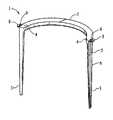
- FIG. 1is a side perspective view of a surgical staple according to the present invention
- FIG. 2is a side orthogonal view of a surgical staple according to the present invention.
- FIG. 3is a top orthogonal view of a surgical staple according to the present invention.
- FIG. 4is a bottom orthogonal view of a surgical staple according to the present invention.
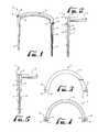
- FIG. 5is a side orthogonal view of one embodiment of a surgical staple according to the present invention.
- FIGS. 6A-6Idepict a system and steps of a method for inserting a surgical staple for repairing bone fractures in accordance with the present invention
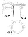
- FIG. 7is a side perspective view of a surgical staple according to the present invention.
- FIG. 8is a side orthogonal view of a surgical staple according to the present invention.
- FIG. 9is a top orthogonal view of a surgical staple according to the present invention.
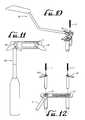
- FIG. 10is a side perspective view of a guide device according to the present invention.
- FIG. 11is a top orthogonal view of a guide device according to the present invention.
- FIG. 12is a side perspective view of an adjustable assembly of a guide device according to the present invention.
- the present inventionovercomes disadvantages of the prior art, as identified and disclosed by the inventor, by providing an improved compression staple and an easy-to-use system and method for its insertion for the internal fixation of bone fractures, fusions, and osteotomies. More specifically, the present invention includes a robust grooved and tabbed surgically implantable staple and can be easily inserted over guide wires and across a fractured bone to provide stability and compression across the desired site.
- the compression staplecan be made of a shape memory metal material or alloy, such as nickel titanium, or another metal material or alloy, such as stainless steel or titanium.
- the stapleis preferably made of a non-corrodable metal material compatible with use in the body.
- the staplemay also be made of a bio-absorbable material. Other materials used for bone fixation include vitalium, chrome cobalt, and suitable bio-compatible polymeric materials.
- the staple 1includes a bridge 2 , e.g., a middle bridge portion, and two legs 3 at each end 4 of the bridge portion 2 that extend substantially perpendicular to the middle bridge portion 2 .
- the legs 3 of the staple 1can be formed in any shape, including, but not limited to, a flat shape or a circular shape. Because the staple's legs 3 can be substantially parallel, the compression is more evenly distributed throughout the staple, whereas staples like those in the prior art that have legs converging towards one another provide little to no compression at the bridge 2 end of the staple 1 .
- the legs 3 of the staplecan also be converging towards one another, especially when using a staple 1 made from a shape memory material.
- the legs 3 of the staple 1are substantially solid and have at least two elevations, an inner elevation 22 and an outer elevation 23 , that run down the length of each staple leg 3 .
- the inner elevation 22can be defined as the inner most surface of the leg 3 .
- the outer elevation 23can be defined as the outer most surface of the leg 3 .
- the inner elevation and outer elevationcan form U-shaped grooves 5 that run down the entire length of each staple leg 3 , however, it is not necessary that a U-shaped groove be formed nor that the grooves 5 be formed along the entire length of each staple leg 3 .
- the inner elevation and outer elevationcan also form an L-shaped groove 5 along the length of each staple leg 3 (not shown).
- the bridge-to-leg interface 4is solid, therefore the staple 1 avoids any problems of weakness or breakage in the staple's legs 3 or bridge-to-leg interface 4 that hollow or cannulated staple legs can create.
- the legs 3 of the staple 1can be tapered or not tapered towards the ends of the legs 3 that are distal from the bridge 2 . Also, the distal ends of legs 3 of the staple can be blunt or formed to an acute point.
- each leg 3 of the staplecan run down the outer edges 6 of the legs 3 .
- the grooves 5can run down the inner edges of each of the legs 3 (not shown).
- the grooves 5can also be described as a recess. The function of the groove 5 is served so long as the leg 3 has at least two elevations relative to the central axis of the leg.
- the shape and diameter of the grooves 5coincide with the shape and diameter of the guide wires 7 in which the staple 1 is inserted over.
- the grooves 5are in a semi-circular shape.
- a tab 8with a hole 9 in each tab 8 equal to or greater than the diameter to that of the guide wire 7 .
- the hole 9 in each tab 8is sized to accomodate a guide wire 7 , and is oriented directly above the groove 5 in the outer edge 6 of each of the staple's legs 3 .
- the staple 1can be formed without the tabs 8 or can be formed with the tabs 8 extending downward along the entire length of each staple leg 3 .
- each tab 8essentially forms an outer edge 6 of each staple leg 3 so that a hole forms axially through the entire length of each staple leg 3 .
- the resulting holes in the staple's legs 3are capable of receiving guide wires 7 just as the recesses or grooves 5 of the staple 1 are.
- a surgeoncan insert guide wires 7 into bone, which remain in place while holes are drilled around the guide wires 7 using a specialized drill 10 that is capable of receiving the guide wires through its drill bit.
- the staple 1is subsequently aligned with the guide wires 7 and inserted into the drilled holes.
- the staple's holes 9 in its tabs 8 and grooves 5 along its legs 3are sized to accommodate the passage of guide wires 7 while inserting the staple 1 .
- the diameters of the holes 9 , grooves 5 , and guide wires 7can vary depending on the surgical procedure but should be complimentary to each other.
- the staple 1can be inserted over or along the guide wires 7 by placing the holes 9 in the tabs 8 over the wires 7 , which automatically positions the grooves 5 along the legs 3 of the staple 1 to slide axially down the wires 7 .
- the grooves 5are aligned with the guide wires 7 and are sized to accommodate passage of the guide wires 7 for their insertion into the holes drilled around the guide wires 7 .
- the hole 9 in each tab 8is sized to receive a guide wire 7 therethrough.
- the cannulated tabs 8 at the outer ends 4 of the bridge 2 of the staple 1aid in the placement of the grooves 5 along the guide wires 7 .
- the proper positioning of the staple 1can be verified using fluoroscopic images of the guide wires prior 7 to the drilling of holes or inserting the staple 1 .
- the staples 1can then be placed accurately and there is no need to re-drill the holes to properly insert the staple 1 and repair the bone.
- the procedureis greatly simplified and expedited, while the outcomes of the surgical procedures are improved as well.
- the bridge 2 of the staple 1can be formed in a curved or slight “C” shape. As illustrated in FIGS. 1-5 , the staple's bridge 2 is curved to the side so that its axis is substantially perpendicular to the staple's legs 3 . In another embodiment, the staple's bridge 2 can be curved upward so that its axis is substantially parallel to the staple's legs 3 . In yet another embodiment, the bridge 2 is formed in a substantially circular shape and is perpendicular to the staple's legs, as shown in FIGS. 7-9 . In this embodiment, the bridge 2 is comprised of two “C” shaped extensions 21 that converge at the legs 3 of the staple 1 .
- the staple 1can provide compression through a variety of means, including via manually compressible staples and staples made from memory metal. Besides aligning the staple 1 for proper placement to accept the guide wires 7 , the tabs 8 and apertures 9 therethrough serve an additional helpful function for compression.
- a device for compressing the staplecan be inserted into holes 9 in the tabs 8 and used to bring the legs 3 of the staple 1 together after the staple's insertion.
- the staplecan be “memoried” in the compressed position with the legs 3 and ends of “C” shaped bridge 2 close together.
- the insertion toolcan be used to separate the legs 3 from under the bridge 2 and along the grooves 5 located on the inner side of the legs 3 , and push the legs 3 outward when activated.
- the staple 1is inserted over the guide wires 7 before removing the insertion tool. Removal of the insertion tool will allow the staple 1 to return to its compressed position.
- staples made with shape memory alloyscan have a memory transfer temperature that is close to body temperature.
- the stapleWhen the staple is attached with both ends of a broken bone the plate will contract from body heat or applied heat and retain its original shape, thereby exerting a compression force on the broken bone at the place of fracture.
- the mechanism of compressioncan be greatly enhanced by forming the bridge 2 of the staple 1 in a slightly curved or slight “C” shape. For example, when the edges of the “C” are brought together, either by manual compression or the action of memory metal, the legs 3 of the staple 1 in their entirety move toward one another, thereby creating even compression.
- the staple 1can include spikes, barbs, or other similar type of projections 11 along the legs 3 of the staple 1 .
- the projections 11can help stabilize the staple's placement in a bone.
- FIGS. 6A-6Iillustrate components of a surgical device system and a method for inserting the grooved and tabbed compression staple 1 according to the present invention.
- the surgical device system for repairing bone according to the present inventioncomprises grooved and tabbed staples 1 of varying widths and lengths that can be made of various materials; an adjustable width guide device 12 ; guide wires 7 ; drills 13 with drill bits of varying diameters; a depth gauge 14 ; an optional staple insertion/compression device; and an optional tamp or mallet.
- the guide device 12includes two apertures 17 therethrough and is capable of accepting two guide wires 7 at a desired width across the bone fracture for their insertion.
- the width between the apertures 17 therethrough, which guides the two guide wires 7is adjustable so that an appropriate bridge 2 width of the staple 1 can be selected depending on the needs during the surgery.
- the width between the apertures 17can be adjusted by slide-type or other mechanism in which the user can select the position, and lock into place, one or both of the apertures 17 .
- a practitionercan select and lock the width of the guide device 12 itself using a slide-type or other mechanism, which in turn positions the width between the apertures 17 .
- the apertures 17 of the guide device 12can be sized to accept and guide a drill 13 .
- removable inserts 18can be placed in the apertures 17 of the guide device 12 .
- the removable inserts 18are sized to accept the guide wires 7 .
- the inserts 18can subsequently be removed so that the guide device 12 can accept a drill 13 over the guide wires 7 .
- the same guide device 12can be used to both insert the guide wires 7 in a desired position and to guide a drill 13 with a drill bit that accepts the guide wires 7 to drill holes around the guide wires while the guide device 12 remains in the proper position.
- This embodimentis useful when it is necessary to use a device to guide the drill, in order to protect soft tissue while drilling.
- a non-limiting embodiment of the depth gauge 14can be placed over or along the side of a guide wire 7 of a known length and measure the depth of the wire's insertion at one end of the wire thereof.
- the difference in the position of the wire 7 in the depth gauge 14 before and after the wire's insertionindicates what length of the staple's legs 3 is appropriate to use.
- the depth gauge 14simplifies measurement of the hole bored in the bone.
- the depth gauge 14also determines whether the hole in the bone is at the desired depth.
- the guide wire 7itself can have an indicator, such as a ruler-type indicator, that measures and displays the depth of its insertion and therefore determines the appropriate length of the fastener to use.
- the depth gauge 14 and guide wires 7can use an electronic or manual means of displaying the depth measurement.
- the drill 13is shown in FIG. 6G , and includes a drill bit having an axially disposed aperture therethrough for accommodating the guide wire 7 .
- the drill bitcan be placed directly above the guide wire 7 and accepts the guide wire 7 through the axially disposed aperture of the drill bit.
- the drillis lowered toward the bone while surrounding the guide wire 7 , and a hole can be drilled directly around the guide wire 7 in the desired area of the bone marked by the guide wire 7 .
- the drill 13allows for minimal incision conditions so that guide wires 7 stay in place during and after drilling the holes in the bone so that the staple may be inserted directly after the hole is made in the bone around the guide wire 7 without removal of the guide wire 7 .
- the drill 13can use instrumentation that is power-driven or instrumentation that is manipulated manually by hand.
- the drill 13can also be used with drill bits of varying diameters.
- FIG. 6Ashows the fractured bone.
- the fracture, osteotomy or fusion siteis exposed, prepared and reduced using standard surgical dissection and reduction techniques as illustrated in FIGS. 6A to 6C .
- the adjustable guide device 12is then set at the desired width, which is determined by positioning the guide 12 over the appropriate site.
- Guide wires 7are then inserted through the guide device 12 while maintaining the guide in proper position.
- the guide wires 7are adapted so that they can be inserted into the bone without requiring a pre-drilled hole prior to their insertion and lodging in the bone.
- FIG. 6Ashows the fractured bone.
- the fracture, osteotomy or fusion siteis exposed, prepared and reduced using standard surgical dissection and reduction techniques as illustrated in FIGS. 6A to 6C .
- the adjustable guide device 12is then set at the desired width, which is determined by positioning the guide 12 over the appropriate site.
- Guide wires 7are then inserted through the guide device 12 while maintaining the guide in proper position.
- the guide wires 7are adapted so that
- the guide device 12is removed and the position of the guide wires 7 can be confirmed clinically and fluoroscopically.
- a depth gauge 14is used to assess the appropriate length of the staple's legs 3 by measuring the exposed length of the wire 7 .
- FIGS. 6H and 6Ithe appropriate sized tabbed and grooved staple 1 is aligned with the guide wires 7 and inserted into the bone.
- the guide wires 7are subsequently removed.
- the compressing feature of the staple 1can be activated automatically, manually or by the use of heat as needed, as described above.
- a tamp or malletcan be used as needed to further seat the staple.
- Final fluoroscopic imagescan be obtained to confirm placement and reduction before flushing and closing in the typical manner known in the art.
- both the guide wires 7 and the drill 13can be guided into the bone using the guide device 12 .
- a usercan place the guide device 12 in a desired position over a bone fracture and then select the desired position or width between the apertures 17 .
- Guide wires 7can be inserted through the inserts 18 of the apertures 17 and into bone fragments. Once the guide wires 7 are in place, the inserts 18 can be removed. The user can then drill around the guide wires 7 and through the apertures 17 of the guide device 12 with a drill 13 as described above.
- the guide device 12After drilling, the guide device 12 is removed and a surgical staple 1 can be aligned with and guided by the guide wires 7 and inserted into the drilled holes in the bone.
- the guide wires 7can be removed, and the staple 1 can be compressed and seated.
- the positions of the guide wires 7 and the staple 1can be confirmed fluoroscopically.
Landscapes
- Health & Medical Sciences (AREA)
- Surgery (AREA)
- Life Sciences & Earth Sciences (AREA)
- Heart & Thoracic Surgery (AREA)
- Molecular Biology (AREA)
- Veterinary Medicine (AREA)
- Engineering & Computer Science (AREA)
- Biomedical Technology (AREA)
- Orthopedic Medicine & Surgery (AREA)
- Medical Informatics (AREA)
- Nuclear Medicine, Radiotherapy & Molecular Imaging (AREA)
- Animal Behavior & Ethology (AREA)
- General Health & Medical Sciences (AREA)
- Public Health (AREA)
- Rheumatology (AREA)
- Dentistry (AREA)
- Oral & Maxillofacial Surgery (AREA)
- Surgical Instruments (AREA)
Abstract
Description
Claims (11)
Priority Applications (2)
| Application Number | Priority Date | Filing Date | Title |
|---|---|---|---|
| US12/275,133US8679123B2 (en) | 2008-11-20 | 2008-11-20 | Surgical device, system and method of use thereof |
| US12/690,053US8888826B2 (en) | 2008-11-20 | 2010-01-19 | Surgical device, system and method of use thereof |
Applications Claiming Priority (1)
| Application Number | Priority Date | Filing Date | Title |
|---|---|---|---|
| US12/275,133US8679123B2 (en) | 2008-11-20 | 2008-11-20 | Surgical device, system and method of use thereof |
Related Child Applications (1)
| Application Number | Title | Priority Date | Filing Date |
|---|---|---|---|
| US12/690,053Continuation-In-PartUS8888826B2 (en) | 2008-11-20 | 2010-01-19 | Surgical device, system and method of use thereof |
Publications (2)
| Publication Number | Publication Date |
|---|---|
| US20100125275A1 US20100125275A1 (en) | 2010-05-20 |
| US8679123B2true US8679123B2 (en) | 2014-03-25 |
Family
ID=42172597
Family Applications (1)
| Application Number | Title | Priority Date | Filing Date |
|---|---|---|---|
| US12/275,133Active2031-04-02US8679123B2 (en) | 2008-11-20 | 2008-11-20 | Surgical device, system and method of use thereof |
Country Status (1)
| Country | Link |
|---|---|
| US (1) | US8679123B2 (en) |
Cited By (25)
| Publication number | Priority date | Publication date | Assignee | Title |
|---|---|---|---|---|
| USD777329S1 (en) | 2015-10-19 | 2017-01-24 | Nextremity Solutions, Inc. | Bone staple |
| US20170339938A1 (en)* | 2016-05-24 | 2017-11-30 | Douglas Gerard Ehrmann | Hoof tap device |
| US10285689B2 (en) | 2015-01-07 | 2019-05-14 | Biomet C.V. | Orthopedic implant for bone fixation |
| US10299842B2 (en) | 2013-12-20 | 2019-05-28 | Crossroads Extremity Systems, Llc | Bone plates with dynamic elements |
| US10357260B2 (en) | 2015-11-02 | 2019-07-23 | First Ray, LLC | Orthopedic fastener, retainer, and guide methods |
| US10376367B2 (en) | 2015-07-02 | 2019-08-13 | First Ray, LLC | Orthopedic fasteners, instruments and methods |
| US10492841B2 (en) | 2014-07-10 | 2019-12-03 | Crossroads Extremity Systems, Llc | Bone implant and means of insertion |
| US10945725B2 (en) | 2017-02-06 | 2021-03-16 | Crossroads Extremity Systems, Llc | Implant inserter |
| US10970789B2 (en) | 2018-01-23 | 2021-04-06 | Full Circle Innovation Llc | Systems and methods for facilitating insurance coverage |
| US11006949B2 (en) | 2018-12-19 | 2021-05-18 | Depuy Synthesis Products, Inc. | Method and apparatus for a shape memory implant |
| US11045190B1 (en)* | 2017-05-08 | 2021-06-29 | Oke Adrian Anakwenze | Surgical bone staple device and method of use |
| US11147567B2 (en) | 2018-02-28 | 2021-10-19 | Joint Restoration Foundation, Inc. | Methods and devices for restoration of a bone surface |
| US11154341B2 (en) | 2018-05-22 | 2021-10-26 | Subluxation Safe Asset, LP | Staple and plate hard tissue fixation |
| US11179149B2 (en) | 2017-02-07 | 2021-11-23 | Crossroads Extremity Systems, Llc | Counter-torque implant |
| US11202626B2 (en) | 2014-07-10 | 2021-12-21 | Crossroads Extremity Systems, Llc | Bone implant with means for multi directional force and means of insertion |
| US20210401580A1 (en)* | 2010-07-27 | 2021-12-30 | Tenon Medical, Inc. | Sacroiliac Joint Stabilization Prostheses |
| US11317951B2 (en) | 2013-12-20 | 2022-05-03 | Crossroads Extremity Systems, Llc | Bone plates with dynamic elements |
| US11357497B1 (en)* | 2018-05-07 | 2022-06-14 | Oke A Anakwenze | Surgical sheath, staple, and scaffold bone anchor devices |
| USD961081S1 (en) | 2020-11-18 | 2022-08-16 | Crossroads Extremity Systems, Llc | Orthopedic implant |
| USD976093S1 (en) | 2020-09-22 | 2023-01-24 | Milwaukee Electric Tool Corporation | Staple collation |
| US11746815B2 (en) | 2020-09-22 | 2023-09-05 | Milwaukee Electric Tool Corporation | Staple and staple collation |
| US12011154B1 (en)* | 2017-05-08 | 2024-06-18 | Oke A. Anakwenze | Surgical bone stable device and method of use |
| US12059183B2 (en) | 2020-07-31 | 2024-08-13 | Crossroads Extremity Systems, Llc | Bone plates with dynamic elements and screws |
| US20240293118A1 (en)* | 2023-03-02 | 2024-09-05 | Medartis Ag | Compression fastener, instruments and methods |
| US12162125B2 (en) | 2020-10-30 | 2024-12-10 | Milwaukee Electric Tool Corporation | Powered fastener driver |
Families Citing this family (18)
| Publication number | Priority date | Publication date | Assignee | Title |
|---|---|---|---|---|
| US8888826B2 (en)* | 2008-11-20 | 2014-11-18 | Mbrace, Llc | Surgical device, system and method of use thereof |
| US9265500B2 (en)* | 2009-08-19 | 2016-02-23 | Covidien Lp | Surgical staple |
| US9451957B2 (en) | 2011-07-27 | 2016-09-27 | William Casey Fox | Bone staple extrusion instrument and method of use and manufacturing |
| US10512459B2 (en) | 2011-07-27 | 2019-12-24 | William Casey Fox | Bone staple, instrument and method of use and manufacturing |
| HK1201138A1 (en)* | 2011-10-10 | 2015-08-28 | William Casey Fox | Shape changing bone implant for enhanced healing |
| US10064618B2 (en)* | 2012-01-20 | 2018-09-04 | Zimmer, Inc. | Compression bone staple |
| US10405903B1 (en) | 2012-05-04 | 2019-09-10 | Xtraverse, LLC | Fasteners with shape changing zigzag structures and methods using same |
| US9138274B1 (en)* | 2012-05-04 | 2015-09-22 | Xtraverse, LLC | Fasteners with shape changing bellows and methods using same |
| FR2999069B1 (en)* | 2012-12-06 | 2016-03-11 | In2Bones | COMPRESSION STAPLE WITH CONVERGENT LEGS |
| WO2015026357A1 (en)* | 2013-08-22 | 2015-02-26 | Dallen Medical, Inc. | Compression bone staple |
| US9427232B2 (en) | 2013-11-08 | 2016-08-30 | C.R. Bard, Inc. | Surgical fastener |
| EP3166505B1 (en)* | 2014-07-10 | 2019-10-09 | Crossroads Extremity Systems, LLC | Bone implant with anti-rotation |
| USD851250S1 (en)* | 2015-11-19 | 2019-06-11 | Orthovestments, Llc | Bone staple |
| US10383625B1 (en)* | 2015-06-30 | 2019-08-20 | Miguel Angel Pirela-Cruz | Scaphoid fixation with an anatomically designed staple |
| DE102016124593A1 (en)* | 2015-12-23 | 2017-06-29 | Prokon-Lp Engineering Gmbh | Tendon - fixation plate |
| WO2021202008A1 (en) | 2020-03-30 | 2021-10-07 | Wright Medical Technology, Inc. | Orthopedic staple and related instruments |
| US20230181184A1 (en)* | 2021-12-10 | 2023-06-15 | Wright Medical Technology, Inc. | Stabilization devices |
| US20230404582A1 (en)* | 2022-06-15 | 2023-12-21 | Wright Medical Technology, Inc. | Orthopedic staple and related instruments |
Citations (16)
| Publication number | Priority date | Publication date | Assignee | Title |
|---|---|---|---|---|
| US2222517A (en)* | 1938-12-08 | 1940-11-19 | James W Price | Fracture nail and machine for making same |
| US3960147A (en) | 1975-03-10 | 1976-06-01 | Murray William M | Compression bone staples and methods of compressing bone segments |
| US4414967A (en) | 1981-06-22 | 1983-11-15 | Minnesota Mining And Manufacturing Company | Internal fixation of bone, tendon, and ligaments |
| US5053038A (en) | 1989-08-17 | 1991-10-01 | Tenstaple, Inc. | Compression bone staple |
| US5662655A (en) | 1992-07-24 | 1997-09-02 | Laboureau; Jacques Philippe | Osteosynthesis plate-staple |
| US5779707A (en) | 1992-11-13 | 1998-07-14 | Bertholet; Maurice | Link piece for bony elements |
| US5785713A (en) | 1995-04-25 | 1998-07-28 | Jobe; Richard P. | Surgical fixation apparatus |
| US6059787A (en) | 1999-04-26 | 2000-05-09 | Allen; Drew | Compression bone staple apparatus and method |
| US6179840B1 (en) | 1999-07-23 | 2001-01-30 | Ethicon, Inc. | Graft fixation device and method |
| US20020019636A1 (en)* | 1999-04-23 | 2002-02-14 | James Ogilvie | Shape memory alloy sample |
| US6402757B1 (en) | 1999-03-12 | 2002-06-11 | Biomet, Inc. | Cannulated fastener system for repair of bone fracture |
| US6592587B1 (en) | 1999-08-26 | 2003-07-15 | Australian Surgical Design And Manufacture Pty Limited | Surgical screw and guidewire |
| US20030167072A1 (en) | 1999-08-25 | 2003-09-04 | Oberlander Michael A. | Multi-anchor suture |
| US20070093839A1 (en) | 2005-09-12 | 2007-04-26 | Beckendorf Brandon G | Compression staple |
| US7214232B2 (en) | 1999-07-23 | 2007-05-08 | Ethicon, Inc. | Graft fixation device |
| US20070276388A1 (en) | 2004-06-24 | 2007-11-29 | Robertson Daniel P | Surgical staples and methods of use thereof |
- 2008
- 2008-11-20USUS12/275,133patent/US8679123B2/enactiveActive
Patent Citations (18)
| Publication number | Priority date | Publication date | Assignee | Title |
|---|---|---|---|---|
| US2222517A (en)* | 1938-12-08 | 1940-11-19 | James W Price | Fracture nail and machine for making same |
| US3960147A (en) | 1975-03-10 | 1976-06-01 | Murray William M | Compression bone staples and methods of compressing bone segments |
| US4414967A (en) | 1981-06-22 | 1983-11-15 | Minnesota Mining And Manufacturing Company | Internal fixation of bone, tendon, and ligaments |
| US5053038A (en) | 1989-08-17 | 1991-10-01 | Tenstaple, Inc. | Compression bone staple |
| US5662655A (en) | 1992-07-24 | 1997-09-02 | Laboureau; Jacques Philippe | Osteosynthesis plate-staple |
| US5779707A (en) | 1992-11-13 | 1998-07-14 | Bertholet; Maurice | Link piece for bony elements |
| US5785713A (en) | 1995-04-25 | 1998-07-28 | Jobe; Richard P. | Surgical fixation apparatus |
| US6402757B1 (en) | 1999-03-12 | 2002-06-11 | Biomet, Inc. | Cannulated fastener system for repair of bone fracture |
| US20020019636A1 (en)* | 1999-04-23 | 2002-02-14 | James Ogilvie | Shape memory alloy sample |
| US6783531B2 (en) | 1999-04-26 | 2004-08-31 | Drew Allen, DPM | Compression bone staple, apparatus and method |
| US6059787A (en) | 1999-04-26 | 2000-05-09 | Allen; Drew | Compression bone staple apparatus and method |
| US6348054B1 (en) | 1999-04-26 | 2002-02-19 | Drew Allen | Stapling method for fastening a first bone segment to a second bone segment |
| US6179840B1 (en) | 1999-07-23 | 2001-01-30 | Ethicon, Inc. | Graft fixation device and method |
| US7214232B2 (en) | 1999-07-23 | 2007-05-08 | Ethicon, Inc. | Graft fixation device |
| US20030167072A1 (en) | 1999-08-25 | 2003-09-04 | Oberlander Michael A. | Multi-anchor suture |
| US6592587B1 (en) | 1999-08-26 | 2003-07-15 | Australian Surgical Design And Manufacture Pty Limited | Surgical screw and guidewire |
| US20070276388A1 (en) | 2004-06-24 | 2007-11-29 | Robertson Daniel P | Surgical staples and methods of use thereof |
| US20070093839A1 (en) | 2005-09-12 | 2007-04-26 | Beckendorf Brandon G | Compression staple |
Cited By (40)
| Publication number | Priority date | Publication date | Assignee | Title |
|---|---|---|---|---|
| US12115075B2 (en)* | 2010-07-27 | 2024-10-15 | Tenon Medical, Inc. | Sacroiliac joint stabilization prostheses |
| US20210401581A1 (en)* | 2010-07-27 | 2021-12-30 | Tenon Medical, Inc. | Sacroiliac Joint Stabilization Prostheses |
| US20210401580A1 (en)* | 2010-07-27 | 2021-12-30 | Tenon Medical, Inc. | Sacroiliac Joint Stabilization Prostheses |
| US12115076B2 (en)* | 2010-07-27 | 2024-10-15 | Tenon Medical, Inc. | Sacroiliac joint stabilization prostheses |
| US11871899B2 (en) | 2013-12-20 | 2024-01-16 | Crossroads Extremity Systems, Llc | Bone plates with dynamic elements |
| US11317951B2 (en) | 2013-12-20 | 2022-05-03 | Crossroads Extremity Systems, Llc | Bone plates with dynamic elements |
| US10299842B2 (en) | 2013-12-20 | 2019-05-28 | Crossroads Extremity Systems, Llc | Bone plates with dynamic elements |
| US11109902B2 (en) | 2013-12-20 | 2021-09-07 | Crossroads Extremity Systems, Llc | Bone plates with dynamic elements |
| US10492841B2 (en) | 2014-07-10 | 2019-12-03 | Crossroads Extremity Systems, Llc | Bone implant and means of insertion |
| US11202626B2 (en) | 2014-07-10 | 2021-12-21 | Crossroads Extremity Systems, Llc | Bone implant with means for multi directional force and means of insertion |
| US11284887B2 (en) | 2014-07-10 | 2022-03-29 | Crossroads Extremity Systems, Llc | Bone implant with means for multi directional force and means of insertion |
| US11998191B2 (en) | 2014-07-10 | 2024-06-04 | Crossroads Extremity Systems, Llc | Bone implant with means for multi directional force and means of insertion |
| US10285689B2 (en) | 2015-01-07 | 2019-05-14 | Biomet C.V. | Orthopedic implant for bone fixation |
| US10376367B2 (en) | 2015-07-02 | 2019-08-13 | First Ray, LLC | Orthopedic fasteners, instruments and methods |
| USD777329S1 (en) | 2015-10-19 | 2017-01-24 | Nextremity Solutions, Inc. | Bone staple |
| US10702290B2 (en) | 2015-11-02 | 2020-07-07 | First Ray, LLC | Orthopedic fastener, retainer, and guide |
| US10357260B2 (en) | 2015-11-02 | 2019-07-23 | First Ray, LLC | Orthopedic fastener, retainer, and guide methods |
| US20170339938A1 (en)* | 2016-05-24 | 2017-11-30 | Douglas Gerard Ehrmann | Hoof tap device |
| US10561134B2 (en)* | 2016-05-24 | 2020-02-18 | Douglas Gerard Ehrmann | Hoof tap device |
| US11864753B2 (en) | 2017-02-06 | 2024-01-09 | Crossroads Extremity Systems, Llc | Implant inserter |
| US10945725B2 (en) | 2017-02-06 | 2021-03-16 | Crossroads Extremity Systems, Llc | Implant inserter |
| US11179149B2 (en) | 2017-02-07 | 2021-11-23 | Crossroads Extremity Systems, Llc | Counter-torque implant |
| US11045190B1 (en)* | 2017-05-08 | 2021-06-29 | Oke Adrian Anakwenze | Surgical bone staple device and method of use |
| US12011154B1 (en)* | 2017-05-08 | 2024-06-18 | Oke A. Anakwenze | Surgical bone stable device and method of use |
| US10970789B2 (en) | 2018-01-23 | 2021-04-06 | Full Circle Innovation Llc | Systems and methods for facilitating insurance coverage |
| US11147567B2 (en) | 2018-02-28 | 2021-10-19 | Joint Restoration Foundation, Inc. | Methods and devices for restoration of a bone surface |
| US11357497B1 (en)* | 2018-05-07 | 2022-06-14 | Oke A Anakwenze | Surgical sheath, staple, and scaffold bone anchor devices |
| US11666365B2 (en) | 2018-05-22 | 2023-06-06 | Subluxation Safe Asset, LP | Staple and plate hard tissue fixation |
| US11154341B2 (en) | 2018-05-22 | 2021-10-26 | Subluxation Safe Asset, LP | Staple and plate hard tissue fixation |
| US11006949B2 (en) | 2018-12-19 | 2021-05-18 | Depuy Synthesis Products, Inc. | Method and apparatus for a shape memory implant |
| US12059183B2 (en) | 2020-07-31 | 2024-08-13 | Crossroads Extremity Systems, Llc | Bone plates with dynamic elements and screws |
| US11746815B2 (en) | 2020-09-22 | 2023-09-05 | Milwaukee Electric Tool Corporation | Staple and staple collation |
| USD976093S1 (en) | 2020-09-22 | 2023-01-24 | Milwaukee Electric Tool Corporation | Staple collation |
| USD1013500S1 (en) | 2020-09-22 | 2024-02-06 | Milwaukee Electric Tool Corporation | Staple |
| USD1074418S1 (en) | 2020-09-22 | 2025-05-13 | Milwaukee Electric Tool Corporation | Staple |
| US12180986B2 (en) | 2020-09-22 | 2024-12-31 | Milwaukee Electric Tool Corporation | Staple and staple collation |
| US12162125B2 (en) | 2020-10-30 | 2024-12-10 | Milwaukee Electric Tool Corporation | Powered fastener driver |
| USD961081S1 (en) | 2020-11-18 | 2022-08-16 | Crossroads Extremity Systems, Llc | Orthopedic implant |
| US11992204B1 (en)* | 2021-05-27 | 2024-05-28 | Oke A Anakwenze | Surgical sheath, staple, and scaffold bone anchor devices |
| US20240293118A1 (en)* | 2023-03-02 | 2024-09-05 | Medartis Ag | Compression fastener, instruments and methods |
Also Published As
| Publication number | Publication date |
|---|---|
| US20100125275A1 (en) | 2010-05-20 |
Similar Documents
| Publication | Publication Date | Title |
|---|---|---|
| US8679123B2 (en) | Surgical device, system and method of use thereof | |
| US8888826B2 (en) | Surgical device, system and method of use thereof | |
| US9872688B2 (en) | Soft tissue repair method | |
| US5571109A (en) | System for the immobilization of vertebrae | |
| US8475457B2 (en) | Clip-like implant for osteosynthesis | |
| JP7350790B2 (en) | Orthopedic fixation system and its use | |
| EP1764042A2 (en) | Compression staple | |
| US8685067B2 (en) | Compression plate apparatus | |
| US20060079903A1 (en) | Minimally invasive pedicle screw and guide support | |
| US9883897B2 (en) | Method and apparatus for a compressing plate | |
| US10582957B2 (en) | Bone fixation implant and means of fixation | |
| US10136932B2 (en) | Spinal plate and distraction/compression pin system | |
| US20070005072A1 (en) | Pedicle punch | |
| JP2010537676A (en) | Anchor delivery system | |
| KR20070042146A (en) | Intramedullary Fixation Assembly and Apparatus and Method for Mounting the Same | |
| US11931084B2 (en) | Method and apparatus for an orthopedic fixation system | |
| US11298169B2 (en) | Bone anchor, kit and method of use | |
| US11832832B2 (en) | Drill bits and methods for preparing bone | |
| US11426183B2 (en) | Surgical drill guide | |
| AU2012201417B2 (en) | Angularly stable fixation of an implant |
Legal Events
| Date | Code | Title | Description |
|---|---|---|---|
| AS | Assignment | Owner name:EMBRACE ORTHOPEDIC, LLC, FLORIDA Free format text:ASSIGNMENT OF ASSIGNORS INTEREST;ASSIGNORS:HELME, DANIEL;KINMON, KYLE;REEL/FRAME:025649/0204 Effective date:20110103 | |
| AS | Assignment | Owner name:MBRACE, LLC, FLORIDA Free format text:ASSIGNMENT OF ASSIGNORS INTEREST;ASSIGNOR:EMBRACE ORTHOPEDIC, LLC;REEL/FRAME:026520/0591 Effective date:20110520 | |
| STCF | Information on status: patent grant | Free format text:PATENTED CASE | |
| FEPP | Fee payment procedure | Free format text:MAINTENANCE FEE REMINDER MAILED (ORIGINAL EVENT CODE: REM.) | |
| FEPP | Fee payment procedure | Free format text:ENTITY STATUS SET TO UNDISCOUNTED (ORIGINAL EVENT CODE: BIG.) Free format text:SURCHARGE FOR LATE PAYMENT, LARGE ENTITY (ORIGINAL EVENT CODE: M1554) | |
| MAFP | Maintenance fee payment | Free format text:PAYMENT OF MAINTENANCE FEE, 4TH YEAR, LARGE ENTITY (ORIGINAL EVENT CODE: M1551) Year of fee payment:4 | |
| MAFP | Maintenance fee payment | Free format text:PAYMENT OF MAINTENANCE FEE UNDER 1.28(C) (ORIGINAL EVENT CODE: M1559); ENTITY STATUS OF PATENT OWNER: LARGE ENTITY | |
| FEPP | Fee payment procedure | Free format text:PETITION RELATED TO MAINTENANCE FEES GRANTED (ORIGINAL EVENT CODE: PTGR); ENTITY STATUS OF PATENT OWNER: LARGE ENTITY | |
| MAFP | Maintenance fee payment | Free format text:PAYMENT OF MAINTENANCE FEE, 8TH YEAR, LARGE ENTITY (ORIGINAL EVENT CODE: M1552); ENTITY STATUS OF PATENT OWNER: LARGE ENTITY Year of fee payment:8 |