US8679090B2 - Medical connector with closeable luer connector - Google Patents
Medical connector with closeable luer connectorDownload PDFInfo
- Publication number
- US8679090B2 US8679090B2US12/641,283US64128309AUS8679090B2US 8679090 B2US8679090 B2US 8679090B2US 64128309 AUS64128309 AUS 64128309AUS 8679090 B2US8679090 B2US 8679090B2
- Authority
- US
- United States
- Prior art keywords
- connector
- luer
- valve
- housing
- fluid
- Prior art date
- Legal status (The legal status is an assumption and is not a legal conclusion. Google has not performed a legal analysis and makes no representation as to the accuracy of the status listed.)
- Active, expires
Links
Images


Classifications
- A—HUMAN NECESSITIES
- A61—MEDICAL OR VETERINARY SCIENCE; HYGIENE
- A61M—DEVICES FOR INTRODUCING MEDIA INTO, OR ONTO, THE BODY; DEVICES FOR TRANSDUCING BODY MEDIA OR FOR TAKING MEDIA FROM THE BODY; DEVICES FOR PRODUCING OR ENDING SLEEP OR STUPOR
- A61M39/00—Tubes, tube connectors, tube couplings, valves, access sites or the like, specially adapted for medical use
- A61M39/22—Valves or arrangement of valves
- A61M39/26—Valves closing automatically on disconnecting the line and opening on reconnection thereof
- A61M2039/267—Valves closing automatically on disconnecting the line and opening on reconnection thereof having a sealing sleeve around a tubular or solid stem portion of the connector
- A61M2039/268—Valves closing automatically on disconnecting the line and opening on reconnection thereof having a sealing sleeve around a tubular or solid stem portion of the connector wherein the stem portion is moved for opening and closing the valve, e.g. by translation, rotation
Definitions
- Embodimentsrelate generally to medical connectors through which fluids flow, and in particular, to medical connectors with male luers.
- a male luer connectorcan have a main housing with first and second ends.
- the first end of the housingcan comprise a male luer and a shroud surrounding at least a portion of the male luer.
- the shroudcan have screw threads disposed on an internal wall thereof.
- a tubular valve member with a fluid pathwaycan be disposed within the housing.
- the valve membercan have a tip on its first end. In the region near the tip, one or more fluid holes can be positioned on the valve member so as to provide a fluid pathway therethrough.
- the tipcan be configured to abut snugly against an internal wall of the male luer in a region at or near the first end of the male luer.
- the valve membercan also have one or more struts that can be directed towards the first end.
- the strutscan extend axially through a portion of the housing, and the ends of the struts toward the first end can be positioned within a space between the male luer and the shroud on the first end of the housing.
- a length of medical tubingcan be connected to the connector.
- An end of the tubingcan be attached to the second end of the valve member by adhesive, friction fit, welding, or some other means.
- a resilient member formed, for example, from either a metal and/or an elastomeric materialcan be positioned within the housing and can bias the valve member toward the closed position.
- the tip of the valve memberIn the closed state or position, the tip of the valve member can be pressed into close contact with a portion of the internal wall on the first end of the male luer, and fluid flow from the medical tubing through the tubular valve member can be generally impeded. Fluid generally cannot escape through the opening on the first end of the male luer because such opening can be blocked by the tip of the valve member.
- the resilient memberWhen a force is applied to move or displace the valve member from the housing, the resilient member can be compressed and the tip of the valve member can be displaced toward the open position.
- This displacing forcecan be applied automatically through the action of connecting the male luer to a female end of another medical implement.
- the female connectormakes contact with and exerts a force directed towards the second end against the struts of the valve member. This force moves the valve member towards the second end against the biasing force directed towards the first end exerted by the resilient member.
- valve memberIn this opened state, fluid can be permitted to flow through the opposing holes, around the tip of the valve member, and out of the connector through the gap between the tip of the valve member and the internal wall on the first end of the male luer.
- the valve membercan be automatically advanced in the direction of the second end when the valve member contacts a fluid conduit (e.g., an internal conduit positioned within a female connector) as the male and female connectors are brought together.
- a fluid conduite.g., an internal conduit positioned within a female connector
- the resilient memberWhen the separating force is removed, for example, by detaching the female connector from the first end of the housing, the resilient member once again can draw the housing and the valve member together. This causes the tip on the first end of the valve member to abut closely against a portion of the internal wall in a region near the first end of the male luer, and impedes fluid flow out of the valve.
- a medical connectorincluding a substantially rigid housing having a first end and a second end wherein the first and second ends are connected by a selectively closable fluid passageway.
- the first endcan include a hollow male luer with an inner surface, a first open end, and a second base end.
- the connectorcan further include a first valve member supported substantially within the housing, the first valve member being configured to selectively seal an opening adjacent to the first end of the housing at the tip of the male luer when the connector is in a closed position and an internal bladder member positioned within the housing and outside the male luer, the bladder member defining an inner cavity and being fluidly coupled to the first valve member, the inner cavity of the bladder member having a first volume in the connector closed position and a second volume smaller than the first volume when the connector is in an open position.
- the rigid housingmay extend laterally from the base of the male luer and an activation arm may extend through the housing adjacent the base of the male luer, a first end of the activation arm configured to engage a corresponding female end of a medical implement and a second end of the activation arm configured to engage at least a portion of the bladder member.
- the bladder member of the connectorcan include a wall portion being concave toward a longitudinal axis of the connector so as to form a substantially ovular inner cavity.
- the bladder memberincludes a corrugated wall portion.
- at least a portion of the bladder member and at least a portion of the valve memberare integrally formed.
- the connectorincludes an annular ring between the valve member and the inner surface of the male luer.
- the annular ringcan be integrally formed with the valve member and can remain in sliding engagement with the inner surface of the male luer between both the closed and open positions of the connector.
- the inner surface of the male luercan include an annular channel and the annular ring can be recessed into said annular channel and can be in sliding engagement with the outer surface of the valve member.
- the second endcan have a female connector portion having an opening axially therethrough.
- An internal bladder membercan be positioned within the housing so that it is outside of the female connector portion so as to be between an end wall of the housing adjacent to the female connector portion and between a valve member positioned within a male luer connector portion of the medical connector.
- the bladder membercan define an inner cavity and can be fluidly coupled to the valve member and the female connector portion.
- the inner cavity of the bladder membercan have a first volume in the connector closed position and a second volume smaller than the first volume when the connector is in an open position.
- a protrusioncan project from the female portion (e.g., the end wall of the housing) and can be configured to extend into an opening formed in the bladder member.
- the protrusioncan have an annular recess thereon configured to receive the annular wall forming the perimeter of the opening of the bladder member.
- the opening in the bladder member and the protrusioncan be configured to form a generally liquid or gas tight seal between the protrusion and the bladder member so that the bladder member can be sealably supported by the protrusion and, hence, the end wall of the housing.
- a protrusioncan project from the valve base and can be configured to extend into a second opening formed in the bladder member.
- the protrusioncan have an annular recess thereon configured to receive the annular wall forming the perimeter of the second opening of the bladder member.
- the second opening in the bladder member and the protrusioncan be configured to form a generally liquid or gas tight seal between the protrusion and the bladder member so that the bladder member can be sealably supported by the protrusion and, hence, the valve base.
- one or more activation armscan be supported by the valve base. The activation arms can be integrally formed with the valve base or otherwise attached to or supported by the valve base.
- a closeable male luerhaving a rigid housing, a valve member supported within the housing, and a first end portion.
- the first end portioncan be, inter alia, a male luer tip.
- the valve membercan extend into an opening formed in the first end portion and move between a first or closed position (wherein liquid is substantially prevented from flowing through the valve member and tip) and a second or open position (wherein liquid is permitted to flow through the valve member and tip).
- the valve membercan be configured to be moveable between a first and a second position by imparting a force directly on a portion of the valve member, such as without limitation, a tube member projection from a valve base.
- the closeable male luercan further comprise, without limitation, struts or activation arms projecting from a valve base of the valve member toward a first end of the medical connector.
- the strutscan be configured such that an axial force imparted on the valve struts can be transferred to the valve base so as to displace the valve member.
- the strutscan be configured to engage a proximal end of a female connector engaged with the closeable male luer as the female connector threadably or otherwise advances into engagement with the closeable male luer.
- a valve tubecan be supported by or attached to the valve base, and can project from the valve base such that, in the assembled configuration, the valve tube extends into an opening formed in the male luer tip.
- a diaphragm member formed from a generally liquid impermeable resilient materialcan be supported within the housing.
- the diaphragm membercan have a generally planar shape or a pair of generally parallel, planar surfaces.
- the diaphragm membercan also have, but is not required to have, a generally annular, disc-like shape.
- the diaphragm membercan be positioned such that an outer periphery of the diaphragm member is sealably supported by the housing.
- An annular recesscan be formed in the housing to support the outer periphery of the diaphragm member.
- the outer periphery of the diaphragm membercan be positioned between a portion of each of two housing portions.
- An openingcan be formed in the diaphragm member, the opening configured to receive an aft portion of the valve base so that the diaphragm member can be sealably secured to the valve member.
- a projection extending from the valve basecan be received within the opening in the diaphragm member.
- the projectioncan define a recess configured to receive and support the opening formed in the diaphragm member.
- the diaphragm membercan be positioned so as to exert a force on the valve member that biases the valve member toward the closed position.
- the diaphragm membercan bias the tube member projecting from the valve base to sealably close against the inside surface of the luer tip.
- the diaphragm membercan be positioned within the luer connector so that, when the valve member is in the closed position, the diaphragm is partially deflected from its relaxed state so as to increase the bias force that the diaphragm exerts on the valve member.
- the diaphragm membercan form a partition within the housing so as to create a substantially fluid sealed cavity or chamber within the housing.
- the diaphragm membercan be configured so that the volume within the cavity when the valve member is in the closed position is greater than volume within the cavity when the valve member is in the open position. In this configuration, the volume of space within the cavity can increase when the valve member moves from the open position to the closed position, thereby creating a force of suction that can reduce the amount of fluid or medicament that can flow through or drip out of an opening in the male luer tip as the valve member closes, by drawing such fluid back toward the cavity.
- the valve membercan be configured such that the valve struts are directly attached to either the tube or the valve base so that an axial force imparted on the valve struts that causes the valve struts to displace also causes at least a portion of the diaphragm member to displace in addition to causing the tube and/or the valve base to displace.
- the valve strutscan be separate from the valve base or the tube so as to move independently compared to the valve base or the tube.
- the strutscan each can exert an axial force on at least a portion of the diaphragm when the struts are displaced due to the engagement of a female connector with the first end portion of the housing, thereby deflecting the diaphragm.
- the valve membercan be moved toward the open position because the diaphragm can be secured to the valve base.
- the bladder membercan have a generally cylindrical or tubular shape, and can be positioned within the housing so that the opening axially through the bladder member is generally coaxially aligned with an opening formed in a female connector portion of the housing and an opening formed in the male luer tip.
- the bladder membercan have one end surface that can be sealably supported by or positioned against an end wall surface adjacent to the female connector portion of the housing.
- a second end surface of the bladder membercan be sealably supported by or positioned against a valve base of the valve member so as to define a chamber or cavity bounded generally by the tubular wall of the bladder member, the end wall of the housing, and the valve member.
- An opening formed through the end wall of the housing and an opening formed in the valve membercan be in communication with the chamber.
- the volume within the chamber when the luer connector is in the closed positioncan be larger than the volume within the chamber when the luer connector is in the open position.
- the increase in the volume of the chamber as the valve member moves from the open to the closed positioncan create a reduced pressure that draws the fluid from the luer tip or tube back into or toward the chamber.
- Some embodimentsprovide a method for selectively closing a medical connector, the method comprising supporting a resilient bladder member within a housing, moving a valve member at least partially supported within the housing between a connector open position and a connector closed position such that, in the closed position, the valve member substantially prevents liquid from flowing through the fluid passageway and, in the open position, the valve member permits liquid to pass through the fluid passageway, and moving the bladder member between a first configuration having a first volume in the connector closed position and a second configuration having a second volume in the connector open position.
- the second volumecan be, but is not required to be, smaller than the first volume.
- the housingcan have a first end and a second end, said first and second ends being connected by a selectively closable fluid passageway and said first end having a hollow male luer with an inner surface.
- the bladder membercan have a corrugated wall portion.
- the bladder membercan have an opening therethrough and an internal chamber in communication with the fluid passageway. Further, the bladder member can be, but is not required to be, supported within the housing so as to be outside the male luer.
- moving the valve member between the connector open position and the connector closed position and moving the bladder member between the first configuration and the second configurationcan comprise engaging or disengaging the medical connector with or from a corresponding female end of a medical implement.
- moving the bladder member between the first configuration and the second configurationcan comprise moving at least one activation arm between a first and a second position, the at least one activation arm being configured to engage a corresponding female end of a medical implement and having a second end thereof configured to engage at least a portion of the bladder member.
- Moving the at least one activation arm between the first and the second positioncan comprise engaging or disengaging the medical connector with or from a corresponding female end of a medical implement.
- Such embodimentsgenerally include means for permitting or impeding fluid flow through a male luer on a connector, which can be automatically opened upon connection with a corresponding female connector.
- Such embodimentsalso include features and configurations that permit the female portion of the male luer connector to be coupled with a corresponding male luer portion of a male luer connector or other component such as a syringe.
- FIG. 1Ais a perspective view of an embodiment of a male luer connector attached to tubing configured to receive fluid from a hanging gravity-fed IV bag.
- the relative size of the connector and attached tubingis increased in comparison to other objects to facilitate viewing certain details.
- FIG. 1Bshows a perspective view of an embodiment of the male luer connector of FIG. 1A being connected to an example of a female connector attached to tubing inserted into a patient.
- FIG. 2Ais a side view of the outside of the embodiment of the luer connector shown in FIG. 1A .
- FIG. 2Bis a cross-sectional view of the embodiment of the luer connector shown in FIG. 1A in a closed position.
- FIG. 2Cis a cross-sectional view of the embodiment of the luer connector shown in FIG. 1A in an open position.
- FIG. 2Dis an enlarged section view of a portion of the embodiment of the luer connector shown in FIG. 2C , defined by the curve 2 D- 2 D in FIG. 2B .
- FIG. 2Eis a cross-sectional view of another embodiment of a luer connector in a closed position.
- FIG. 2Fis a cross-sectional view of the embodiment of the luer connector shown in FIG. 2E in an open position.
- FIG. 2Gis a cross-sectional view of another embodiment of a luer connector in a closed position.
- FIG. 2His a cross-sectional view of the embodiment of the luer connector shown in FIG. 2G in an open position.
- FIG. 2Iis a cross-sectional view of another embodiment of a luer connector in a closed position.
- FIG. 2Jis a cross-sectional view of the embodiment of the luer connector shown in FIG. 2I in an open position.
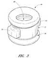
- FIG. 3is an enlarged perspective view of an embodiment of a sealing member.
- FIG. 4Ais a cross-sectional view of another embodiment of a luer connector in a closed position.
- FIG. 4Bis a cross-sectional view of the embodiment of the luer connector shown in FIG. 4A in an open position.
- FIG. 4Cis a cross-sectional view of another embodiment of a luer connector in a closed position.
- FIG. 4Dis a cross-sectional view of the embodiment of the luer connector shown in FIG. 4C in an open position.
- FIG. 5Ais a cross-sectional view of another embodiment of a luer connector in a closed position.
- FIG. 5Bis a cross-sectional view of the embodiment of the luer connector shown in FIG. 5A in an open position.
- FIG. 5Cis a cross-sectional view of another embodiment of a luer connector in a closed position.
- FIG. 5Dis a cross-sectional view of the embodiment of the luer connector shown in FIG. 5C in an open position.
- FIG. 6Ais a cross-sectional view of another embodiment of a luer connector in a closed position.
- FIG. 6Bis a cross-sectional view of the embodiment of the luer connector shown in FIG. 6A in an open position.
- FIG. 6Cis a cross-sectional view of another embodiment of a luer connector in a closed position.
- FIG. 6Dis a cross-sectional view of the embodiment of the luer connector shown in FIG. 6C in an open position.
- FIG. 7Ais a side view of another embodiment of a luer connector.
- FIG. 7Bis a cross-sectional view of the embodiment of the luer connector shown in FIG. 7A in a closed position.
- FIG. 7Cis a cross-sectional view of the embodiment of the luer connector shown in FIG. 7A in an open position.
- FIG. 7Dis a cross-sectional view of another embodiment of a luer connector in a closed position.
- FIG. 7Eis a cross-sectional view of the embodiment of the luer connector shown in FIG. 7D in an open position.
- FIG. 7Fis a cross-sectional view of another embodiment of a luer connector in a closed position.
- FIG. 7Gis a cross-sectional view of the embodiment of the luer connector shown in FIG. 7F in an open position.
- FIG. 8Ais a cross-sectional view of another embodiment of a luer connector in a closed position.
- FIG. 8Bis a cross-sectional view of the embodiment of the luer connector shown in FIG. 8A in an open position.
- FIG. 8Cis a cross-sectional view of another embodiment of a luer connector in a closed position.
- FIG. 8Dis a cross-sectional view of the embodiment of the luer connector shown in FIG. 8C in an open position.
- the male luerincludes closing mechanisms which function to prevent and/or impede fluid from escaping from or entering into the male luer, while allowing fluid flow when the male luer is manually opened or engaged with a corresponding female luer.
- closing mechanismswhich function to prevent and/or impede fluid from escaping from or entering into the male luer, while allowing fluid flow when the male luer is manually opened or engaged with a corresponding female luer.
- Some medicationscan be harmful to a patient in certain applications. For example, exposure to the skin can sometimes result in a chemical burn. Inhalation of aerosolized forms of some medications also can be harmful. Thus, control over the containment of the medication is highly desirable.
- the medicationcan be removed from the vial by inserting a needle and drawing the medication into a syringe.
- the needlecan be then withdrawn from the vial and the medication can be dispensed.
- the needlemay be withdrawn with a residue of medication disposed on the outside of the needle.
- This medicationcan inadvertently come in contact with the skin and cause harm.
- a vial adapteris used to penetrate the vial with a withdrawal mechanism, the medication can be drawn through the mechanism and passed directly to a syringe for injection without the additional step of withdrawing the mechanism from the vial.
- FIG. 1Ais a perspective view of an embodiment of a male luer connector in an example of use in which it is attached to tubing configured to receive fluid from a hanging gravity-fed IV bag.
- an embodiment of a closeable male luer connector 10is shown in a closed position.
- the luer connector 10can be attached to a gravity-fed IV bag 9 filled with fluid hanging from a pole stand 11 .
- a section of tubing 13can be attached.
- the opposite end of the tubing 13can be connected to the second or distal end 14 of the luer connector 10 .
- a closing mechanism on the interior of the first or proximal end 12 of the luer connector 10can prevent the fluid contained within the bag 9 from flowing through the tubing 13 and leaking out of the luer connector 10 , as long as the luer connector 10 remains in a closed configuration.
- the IV delivery system illustrated in FIG. 1Acan be easily readied for fluid communication with a patient.
- the tubing 13is filled with air when it is initially connected to the IV bag 9 . If the other end of the tubing 13 can be connected to a closed connector, as illustrated in FIG. 1A , the air cannot escape and fluid cannot enter the tubing 13 from the IV bag 9 .
- the luer connector 10can be manipulated so as to be in the open position until all of the air has been purged through the luer 10 and the fluid in the IV bag 9 fills the tubing 13 and connector 10 . This procedure is known as “priming.” As soon as the fluid line and connector are properly primed, the health care provider can then manipulate the luer connector 10 to the closed position to stop the flow of fluid through the luer connector 10 .
- FIG. 1Bshows a perspective view of an embodiment of the male luer connector of FIG. 1A being connected to an example of a female connector attached to tubing inserted into a patient.
- a catheter 17has been inserted into a patient's arm 15 .
- the catheter 17penetrates the skin of the arm 15 and can be fluidly connected with the patient's bloodstream.
- the catheter 17can also be connected to a length of medical tubing 19 attached to a female medical connector 21 .
- the example of a female medical connector 21 illustrated in FIG. 1Bis a version of the Clave® connector manufactured by ICU Medical, Inc., San Clemente, Calif.
- Various embodiments of a connector of this typeare illustrated and described in U.S. Pat. No.
- the tubing 19 , catheter 17 , and female connector 21were preferably previously primed with fluid using standard procedures.
- the luer connector 10can be primed as described previously and brought into engagement with the female connector 21 .
- fluidcan be permitted to flow from the IV bag 9 into the patient.
- the male connector 10 and female connector 21are disengaged, fluid can be once again prevented from flowing out of the first end 12 of the male connector 10 .
- fluidcan also be prevented from flowing out of the opening in the female connector 21 .
- FIGS. 1A-1BThe embodiment illustrated in FIGS. 1A-1B is described in further detail below.
- Each of the other embodiments disclosed hereincan be used in the illustrated fluid system, and in various modifications and alternatives thereof.
- the various embodiments of connectorscan be used in a wide variety of additional medical fluid systems.
- the disclosed connectorscan also be used to transfer bodily fluids such as blood, urine, or insulin, nourishing fluids, and/or therapeutic fluids such as fluids used in chemotherapy treatments.
- the disclosed connectorscan also be used to interconnect various other components of fluid transfer systems.
- FIG. 2Ais a side view of the outside of the luer connector 10 .
- FIG. 2Bis a cross-sectional view of the luer connector 10 in a closed position so that fluid is generally prevented from flowing through the luer connector 10 .
- the valve member 20can be configured to prevent fluid under system pressures from flowing through the connector 20 .
- FIG. 2Bis a cross-sectional view of the luer connector 10 , showing the valve member 20 in an open position. In the open position, the valve member 20 can be positioned so as to not significantly impede the flow of fluid through the luer connector 10 .
- some embodiments of the assembled luer connector 10can comprise a housing 22 , a port 24 positioned near the second end 14 of the luer connector 10 , a luer tip 26 positioned near the first end 12 of the luer connector 10 , a shroud 28 surrounding at least a portion of the luer tip 26 , a diaphragm 30 supported within the housing 22 , and the valve member 20 mentioned above also supported within the housing 22 .
- the diaphragm 30can be formed from a generally fluid impervious, suitably resilient material and may be separately or integrally formed with the valve member 20 .
- the diaphragm 30can generally define an internal cavity 33 .
- the valve member 20can comprise a tube 32 projecting from a valve base 34 toward the first end 12 of the connector 10 , and one or more valve arms or struts 36 can also project from and be supported by the valve base 34 .
- the valve struts 36can be positioned so as to be adjacent to the tip 26 along the sides of the tip 26 .
- the outer surface of at least the distal portion 32 a of the valve tube 32can be sealingly closed against the inner surface of at least the distal portion 26 a of the luer tip 26 such that fluid is generally prevented from flowing through the opening 38 formed in the distal end 26 a of the luer tip 26 .
- luer tip 26corresponds to ANSI standards for medical connectors to facilitate use with various standard medical implements.
- the diameters of the opening 38 in the distal tip portion 26 a of the luer tip 26can be in the ranges of approximately 0.4 mm to approximately 1.8 mm, approximately 0.5 mm to approximately 1.5 mm, and approximately 0.5 to approximately 1.0 mm. Other diameters, either inside or outside the listed ranges can also be used.
- the second end of the valve member 20can be sized appropriately to occupy the space in the opening 38 of the distal end portion 26 a of the luer tip 26 .
- the tube 32can be slidable so as to translate axially within the luer tip 26 .
- the valve struts 36can be supported in a cantilevered disposition by the valve base 34 and can be configured so as to slide within the openings 40 formed through the internal wall 42 of the housing 22 .
- the number of openings 40 through the internal wall 42can be equal to the number of the valve struts 36 supported by the valve base 34 .
- An annular sealing member 44can be positioned between the outside surface of the valve tube 32 and the inside surface of the luer tip 26 so as to prevent any fluid from flowing into the chamber 46 .
- the chamber 46is the space outside the internal cavity 33 generally defined by diaphragm 30 that is generally confined by the end wall 22 a of the housing 22 , the sidewall 22 b (which can be cylindrically shaped) of the housing 22 , and the internal wall 42 formed on the housing 22 .
- the diaphragm 30can be supported near the second end 14 of the luer connector 10 by the end wall 22 a of the housing 22 , laterally by the sidewall 22 b (which can be cylindrically shaped) of the housing 22 , and by the valve member 20 .
- the diaphragm 30can comprise a pair of generally opposing openings 48 a , 48 b , through which fluid can pass.
- the first opening 48 a formed in the diaphragm 30can be sealably supported by a protrusion 50 formed on the end wall 22 a of the housing 22 .
- the second opening 48 b formed in the diaphragm 30can be sealably supported by a protrusion 52 formed on the valve base 34 .
- the first and second openings 48 a , 48 bcan be supported by the protrusions 50 , 52 so that fluid can be generally prevented from leaking into the chamber 46 .
- the diaphragm 30can be resilient and biased toward an expanded position, as illustrated in FIG. 2B , so as to exert a force on the valve member 20 that biases the valve member 20 toward the closed position. Further, the diaphragm 30 can be configured so that the volume of the cavity 33 within the diaphragm 30 when the valve member 20 is in the closed position (which is represented by V 1 in FIG. 2B ) can be greater than the volume of the cavity 33 within the diaphragm 30 when the valve member 20 is in the open position (which is represented by V 2 in FIG. 2C ).
- the volume of the cavity 33 within the diaphragm 30can decrease when the valve member 20 moves from the closed position to the open position and can increase when the valve member 20 moves from the open position to the closed position.
- the diaphragm 30can create a force of suction that reduces the amount of fluid or medicament that can flow through or drip out of the opening 38 as the valve member 20 is in the process of closing, by drawing such fluid back towards the diaphragm 30 .
- valve 20 , the valve base 34 , the valve struts 36 , and the protrusion 52can be integrally formed.
- any of the features of the valve member 20including the valve tube 32 , the valve base 34 , the valve struts 36 , and the protrusion 52 , can be separately formed and adhered or otherwise joined together in subsequent manufacturing steps.
- the end wall 22 acan be formed integrally with at least the sidewalls 22 b of the housing 22 .
- the end wall 22 acan be formed separately as compared to at least the sidewalls 22 b and joined or adhered to the housing 22 in a subsequent manufacturing step, preferably after other components such as the valve member 20 , the diaphragm 30 , and the seals are properly positioned within the housing.
- the housing 22can generally be a tube-like structure with a passageway 54 that can extend from the second end 14 of the connector 10 and preferably through the axial center of the luer connector 10 .
- the passageway 54can permit fluid to flow from the second end 14 through the port 24 , the diaphragm 30 , the tube 32 , and out through the opening 38 in the luer tip 26 positioned at the first end 12 of the luer connector 10 .
- the port 24 and the corresponding section of the fluid passageway 54can be sized and configured so as to accommodate a section of standard-diameter medical tubing inserted therein.
- the port 24is configured to accept a standard male luer corresponding to ANSI standards for medical valves.
- the length of the housing 22 (or any housing described herein) from the second end 14 to the distal end of the luer tip 26can be approximately 0.75 inch.
- the housing 22can have many other sizes.
- the length of the housing 22 (or any housing described herein) from the second end 14 to the distal end of the luer tip 26can be from approximately 0.5 inch to approximately 0.75 inch, or from approximately 0.75 inch to approximately 1.0 inch, or from approximately 1.0 inch to approximately 1.25 inches or more, or from or to any value within these ranges.
- the housing 22can be less than or equal to approximately 1.50 inches from the second end 14 to the distal end of the luer tip 26 so that the weight and bulk of the connector can be minimized.
- the housing 22can have any suitable length for a particular application.
- the shroud 28can have inner threads 56 on an interior wall that help securely attach the connector 10 in a removable fashion to another medical implement.
- the shroud 28can include other structures or materials for providing a releasable connection, including quick-release mechanisms and other means.
- the housing 22 and shroud 28can define a plurality of protrusions 58 or other suitable features on an outer surface to assist the user in firmly grasping and twisting the shroud 28 and the housing 22 with the user's fingers so as to prevent the luer connector 10 from slipping within the user's grasp when the luer connector 10 is twisted.
- the housing 22 or shroud 28may alternatively or additionally define depressions that have upwardly tapering sidewalls that provide additional support to help prevent the fingers from sliding off the connector 10 , or any other features or materials that substantially prevent the fingers from sliding relative to the connector 10 .
- the protrusions 58may extend around substantially the entire outer surface of the housing 20 or shroud 28 so that the user's fingers, when positioned on opposite sides of the connector 10 , will likely encounter a depression, regardless of the orientation of the connector 10 , during use.
- the tip 26can have a tapered external wall.
- the diameter of the tip 26can become gradually smaller from the valve base 34 towards the distal end portion 26 a of the tip 26 .
- the tip 26can define an opening 38 positioned at the distal end portion 26 a of the luer tip 26 .
- an interior space 60(see FIG. 2B ) communicates with the fluid passageway 54 of the luer connector 10 and with the opening 38 so as to provide a fluid flow path through the entire luer connector 10 .
- the term fluid passagewaycan refer to the entire fluid pathway through the luer connector.
- the dimensions of the luer tip and the end capi.e., the male and female ends
- FIG. 2Dis an enlarged section view of a portion of the luer connector 10 , defined by the curve 2 D- 2 D in FIG. 2B .
- the interior wall of the luer tip 26can include a constricted portion 62 that extends radially inwardly toward the axis of the fluid passageway 54 surrounded by the luer tip 26 , making the fluid passageway 54 narrower at the distal end portion 26 a of the luer tip 26 than in the region adjacent to the constricted portion 62 .
- the constricted portion 62can define a generally cylindrically shaped surface 62 a and a generally sloped or tapered surface 62 b .
- the constricted portion 62can further define a second sloped or tapered surface 62 c that can be configured to match a similarly sloped or tapered surface on the distal end portion 32 a of the tube 32 .
- the distal end portion 32 a of the tube 32can be sized and configured so as to complement the size and shape of the constricted portion 62 of the luer tip 26 so as to define a sealable closing mechanism.
- the closing mechanismcan be adapted to close the fluid passage extending through the closeable male luer 10 from fluid communication with the external environment, such as when the male luer 10 is not engaged with a female connector.
- the distal end portion 32 a of the tube 32can be sized and configured so as to complement the generally cylindrically shaped, sloped surface 62 a .
- the tube 32can be further configured to complement the generally sloped surface 62 b and the second sloped surface 62 c of the constricted portion 62 .
- the inner diameter of the constricted portion 62can become narrower so as to generally block and/or impede fluid flow through the connector 10 when the distal end portion 32 a of the tube 32 is abutted against it.
- a closurecan be formed at or near the first end 12 of the male luer 10 .
- the distal end portion 32 a of the tube 32can be made from, or covered by, a different material than is used to form the tube 32 .
- the distal end portion 32 acan be covered with a softer, more malleable or deformable material as compared to the material used to form the tube 32 so as to provide better sealing properties between the distal end portion 32 a of the tube 32 and the luer tip 26 .
- the opening 64 in the distal end portion that can be in fluid communication with the passageway 54can be of any suitable size or shape to improve manufacturability or to most effectively channel the fluid through the luer connector 10 when the valve member 20 is in the open position.
- the holes 52can be formed with a tear-drop shape (e.g., narrow on one end and wider on an opposite end), which may facilitate an injection molding process of manufacture.
- the valve member 20can be constructed without a fluid path and function as a blocking plunger for fluid flowing around the valve member 20 rather than as a means for conveying fluid between the first and second ends of the luer connector 10 .
- the housing 22can be formed in two halves that each define a planar joining surface, such as, but not limited to, a surface 22 c that defines the planar section surface in FIG. 2B .
- the end portion 22 a of the housing 22can be formed in a separate step as compared to the rest of the housing, and subsequently adhered to or otherwise joined to the housing after the two halves described above are adhered or otherwise joined together.
- the housing 22 of the illustrated embodiment, or the housing of any embodiment described hereincan be constructed from any of a number of different materials or combination of materials.
- the housing 22 or any housing described hereincan be constructed from a relatively rigid material, such as polycarbonate or other polymeric material.
- the housing 22 and/or valve member 20 of this embodiment, or the housing and/or the valve member of any embodiment described herein, or any of the components of this or any other embodimentcan also be constructed of a medical grade, hydrophobic material, such as Bayer Makrolon, or any other suitable material.
- the diaphragm 30can comprise a resilient material such that the diaphragm 30 can be compressed into an open position and resiliently return to its original closed position, as described above.
- the diaphragm 30may be formed from a non-rubber silicone or other suitable material depending at least on the medicament or fluid to be passed through the luer connector 10 .
- the diaphragm 30can be generally fluid impermeable so as to generally prevent any fluid from permeating therethrough into the chamber 46 .
- the valve member 20 or any valve member disclosed herein, like the housing 22may be constructed from a number of different materials or combinations of different materials, including the material that is used to form the housing 22 . Examples of such materials include polycarbonate or other polymeric materials. In certain applications, for example, semi-rigid or even more flexible materials may be desirable for use in the valve member 20 , and more particularly for the distal end portion 32 a of the tube 32 .
- the length of the valve member 20can be shorter than the length of the housing 22 .
- Any of the valve assemblies described herein, including but not limited to the valve member 20may be manufactured through injection molding.
- the valve member 20 of the illustrated embodimentcan be configured as shown in FIGS. 2B-2C , many other configurations are possible.
- one or more protrusions or raised tabs 66can be formed on an exterior surface 24 a of the port 24 to facilitate removably attaching a medical implement (not shown) with the second end 14 of the valve member 20 .
- the exterior surface 24 acan be cylindrical except for the protrusions, raised tabs, or other features formed thereon.
- the interior surface 24 b of the port 24can be conically shaped, such that the diameter of the interior surface 24 b can be greatest at the portion of the interior surface 24 b adjacent to the second end 14 of the luer connector 10 .
- the internal taper of the interior surface 24 bcan compliment and closely fit with the taper of a typical male luer. Such an internal taper can conform to ANSI standards and/or regulations, such as the standard for medical syringes.
- the outside surface 26 b of the luer tip 26can also be tapered to conform to ANSI standards and/or regulations, such as the standard for medical syringes.
- the inside surface 26 c of the luer tip 26 and the outside surface 32 b of the tube 32can either be straight or can also be tapered. Tapering the inside surface 26 c of the luer tip 26 and the outside surface 32 b of the tube 32 can help minimize the amount of fluid that flows into and is trapped in the interior space 60 between the tube 32 in the luer tip 26 , since the distance between the tapered inside surface 26 c of the luer tip 26 and the outside surface 32 b of the tube 32 would be reduced as the tube 32 moves toward a closed position.
- the sealing member 44can be configured so as to provide an effective seal between the tube 32 and the luer tip 26 even when the distance of the gap therebetween increases.
- the closeable luer connector 10can have a female mating end at the second end 14 of the luer connector 10 and a male luer mating end at the first end 12 of the luer connector 10 .
- the closeable female connector 21 of FIG. 1B(referenced above), as well as other standard female connectors with similar external structure, can also have both female and male ends.
- such female connectorscan utilize seals or other fluid barriers to impede the flow of fluid on the female end but do not typically do so on the male end.
- the female end of any of the closeable male luer connectors disclosed hereincan be configured to include a closeable female end.
- the structure for selective fluid-impedance with the female connector 21or any of the other standard female connectors, could be included within the female end of any of the closeable male luer connectors disclosed herein to provide a connector that selectively seals or impedes fluid flow on both ends.
- a resilient seal elementit can be advantageous for a resilient seal element to be positioned at or near the female opening, as shown in U.S. Pat. No. 5,685,866 entitled Medical Valve and Method of Use, filed on Nov. 4, 1994, which disclosure is hereby incorporated by reference in its entirety.
- seal elementBy positioning the seal element in this manner, it is possible to cleanse the female opening prior to use with antiseptic with a wiping motion to avoid a harmful accumulation of debris, bacteria, antiseptic, or other unwanted substances on the seal element and/or in the region between the seal element and the housing of the connector adjacent to the seal element.
- the sealing member 44can define an annular cross-section, as illustrated in FIGS. 2B and 2C .
- the luer connector 10can be configured such that an alternative sealing member 44 ′ can be used in place of the annular sealing member described above.
- FIG. 3is an enlarged perspective view of an alternative sealing member 44 ′.
- the sealing member 44 ′can be substantially cylindrical and can have a bore 68 extending axially through the center thereof.
- the sealing member 44 ′can further comprise a pair of generally rectangular protrusions 70 extending from the sidewalls of the cylindrical portion at diametrically opposed positions.
- the protrusions 70can have different shapes and/or positions, and can assist with positioning and/or aligning the sealing member 44 ′ in the desired position.
- the sealing member 44 ′can also have a generally smaller-diameter middle portion 72 surrounded by two rings 74 at either end with larger diameters.
- the sealing member 44 or 44 ′can be constructed from a number of different materials.
- the sealing member 44 or 44 ′can be made from a silicon-based deformable material. Silicon-based deformable materials are among those that can form fluid-tight closures with plastics and other rigid polymeric materials.
- the housing 22 , the valve member 20 , and the sealing member 44are in an assembled configuration, in which the closing mechanism forms a closing engagement between the distal portion 32 a of the tube 32 and the interior of the luer tip 26 .
- the sealing member 44can be in closing engagement between the valve member 20 and the interior surface 26 c of the luer tip 26 .
- fluid flowing through the passageway 54may be able to flow through the opening 64 adjacent to the distal portion 32 a of the tube 32 .
- the opening 64can communicate with the interior space 60 , but not with the external environment.
- FIG. 2Cis a cross-sectional view of the luer connector 10 in an open position, so that fluid can be generally permitted to flow through the luer connector 10 .
- the flow of fluid through the luer connector 10is represented by arrows in FIG. 2C .
- the housing 22 , the valve member 20 , and the sealing member 44are illustrated in an assembled configuration. As shown, the valve member 20 has been moved to the open position by the insertion of the female connector 76 .
- FIG. 2Cillustrates a cross-section of an embodiment of the luer connector 10 wherein the valve member 20 has been caused to be opened by the insertion of an exemplifying female connector 76 .
- the female connector 76can comprise an elongate body 78 having a fluid passageway 80 therethrough, and the female connector 76 can have a tip 82 near its distal end. In some embodiments, the tip 82 of the female connector 76 can have a radially extending surface 84 disposed on its external surface.
- the female connector 76can have a fluid conduit within the female connector 76 . The fluid conduit is not included or required in all female connectors compatible with the connectors 10 disclosed herein.
- the fluid passageway 80can be tapered such that the diameter of the fluid passageway 80 decreases in the distal direction.
- the struts 36 of the valve member 20can extend through openings 40 in the internal wall 42 of the housing 22 such that, in the closed position, the ends of the struts 36 extend past the internal wall 42 toward the first end 12 of the connector 10 .
- the struts 36can be configured to engage the proximal end 84 of the female connector 76 as the female connector 76 advances into engagement with the closeable male luer 10 .
- the radially extending surface or surfaces 84 of the female connector 76can be threaded into the inner threads 56 of the male luer 10 .
- the two luers 10 , 76can be threadedly engaged with one another until the taper of the inner surface 86 of the female luer connector 76 lies adjacent the correspondingly tapered external surface 26 b of the tip 26 .
- the proximal end 84 of the tip of the female connector 76can contact the struts 36 of the valve member 20 .
- the struts 36can be moved toward the second end 14 of the male connector 10 by the female connector 76 .
- the distal end portion 32 acan move away from the interior distal end portion 26 a of the tip 26 in the direction of the second end 14 of the male connector 10 as the male luer connector 10 and female connector 76 move further into threaded engagement.
- a space or gapcan form between the tube 32 and the luer tip 26 , permitting fluid to pass through the opening 38 into the fluid passageway 80 of the female connector 76 , or vice versa.
- an internal fluid conduit of the female connector 76may contact the distal end portion 32 a of the tube 32 before the housing of the female connector 76 contacts the struts 36 , thereby opening the male connector 10 .
- the closuremay remain intact until the inner surface 86 of the tip of the female connector 76 has formed a closing engagement with the outer surface of the tip 26 of the male luer 10 , substantially limiting fluid within the passageway 54 of the male luer 10 from being exposed to the external environment.
- the resilient diaphragm 30can compress, causing the diaphragm 30 to exert a biasing force on the valve member 20 toward the closed position or causing the diaphragm 30 to increase the biasing force exerted on the valve member 20 .
- the biasing force from the diaphragm 30can be resisted by the radially extending surface 84 of the female connector 76 contacting the inner threads 56 of the housing 22 .
- the diaphragm 30can return the sealing portion of the valve member 20 to the closed position within the luer tip 26 .
- the sealing member 44can maintain a fluid barrier between the outer surface of the tube 32 and the inner surface of the luer tip 26 .
- the position of the sealing member 44can be maintained by the protrusions 70 .
- the sealing member 44can be positioned by adhering the outer surface of the protrusions 70 to an inner surface of the luer tip 26 .
- the sealing member 44can be positioned by adhering the outer surface of the seal 44 to an inner surface of the luer tip 26 or to an outer surface of the valve tube 32 .
- Other suitable means of fixing the position of the sealing member 44can also be used.
- the fluid passageway 80 of the female connector 76can communicate with the passageway 54 of the valve member 20 so as to allow fluid to flow through the passageway 54 and the fluid passageway 80 of the female connector 76 in either direction. Fluid can thereby flow from tubing (not shown) or another connector or conduit that can be attached to the luer connector 10 , into the passageway 54 of the housing 22 , through the opening or openings 64 into the interior space 60 within the luer tip 26 , out from the interior space 60 within the luer tip 26 through the opening 38 at the distal end portion 26 a of the luer tip 26 and into the fluid passageway 80 of the female connector 76 , and vice versa.
- a fluid-tight closurecan also be formed between corresponding tapers of the outside surface of the tip 26 and the inner surface 86 of the female connector 76 .
- the valve member 20can cause the diaphragm 30 to be compressed and the volume of fluid that can be contained within the cavity 33 of the diaphragm 30 can accordingly decrease.
- the fluid within the diaphragm 30can be subjected to an increased pressure due to the compression of the diaphragm 30 .
- the female connector 76With the female connector 76 fully connected, the volume of the cavity 33 in the diaphragm 30 can be reduced to V 2 .
- V 1can be larger than V 2 , and in some embodiments, the difference in volume between V 1 and V 2 can generally correspond to the volume of residual fluid, such as a drip, that is expected to remain on the outside of the male luer upon disconnection from the female luer.
- the valve member 20when the female connector 76 is removed from the luer connector 10 , and the valve member 20 can move back toward the closed position, thereby causing the volume within the cavity 33 of the diaphragm 30 to expand back to the closed position volume V 1 .
- the expansion of the interior volume of the diaphragm 30can cause a reduced pressure or suction to be generated within the diaphragm 30 .
- This reduced pressure or suctioncan cause the cavity 33 to draw at least some of the fluid that is within the passageway 60 within the luer tube 26 or on the outside surface of the end of the tube 32 a back into the diaphragm 30 .
- the suction or draw-backis beneficial in that it can prevent fluid from dripping out of the opening 38 as the female connector 76 is being removed.
- the luer connector 10may be used to control the flow of fluids or medicaments that are harmful or corrosive, such as by substantially preventing one or more drops from dripping out of the opening 38 as the female connector 76 is being removed.
- FIG. 2Eis a cross-sectional view of the luer connector 10 ′ in a closed position. As described above, when the valve member 20 ′ of the luer connector 10 ′ is in the closed position, fluid is generally prevented from flowing through the luer connector 10 ′.
- FIG. 2Eis a cross-sectional view of the luer connector 10 ′ in a closed position. As described above, when the valve member 20 ′ of the luer connector 10 ′ is in the closed position, fluid is generally prevented from flowing through the luer connector 10 ′.
- FIG. 2Fis a cross-sectional view of the embodiment of the luer connector 10 ′ taken through the longitudinal center of the luer connector 10 ′, showing the valve member 20 ′ in an open position due to the engagement of a female connector 76 with the luer connector 10 ′.
- the flow of fluid through the luer connector 10 ′is represented by arrows in FIG. 2F .
- fluidcan be generally permitted to flow through the luer connector 10 ′.
- the luer connector 10 ′can be the same or similar to the luer connector 10 described above, with certain differences as illustrated and/or described below. Accordingly, in some embodiments, the luer connector 10 ′ may operate in the same or similar manner as compared to the luer connector 10 described above.
- the valve member 20 ′can comprise a tube 32 ′ projecting from a valve base 34 ′ toward the first end 12 ′ of the connector 10 ′, and one or more arms or struts 36 ′ supported by the valve base 34 ′ such that an axial force imparted on the valve struts 36 ′ is generally transferred directly to the valve base 34 ′. As shown in FIG.
- the struts 36 ′ of the valve member 20 ′can extend through openings 40 ′ in the internal wall 42 ′ of the housing 22 ′ such that, in the closed position, the ends of the struts 36 ′ extend past the internal wall 42 ′ toward the first end 12 ′ of the connector 10 ′.
- an annular seal 45 ′can seal each of the openings 40 ′ through which a valve strut 36 ′ passes.
- the struts 36 ′can be configured to engage the proximal end 84 of the female connector 76 as the female connector 76 advances into engagement with the closeable male luer 10 ′.
- the radially extending surface or surfaces 84 of the female connector 76can be threaded into the inner threads 56 ′ of the male luer 10 ′.
- the valve struts 36 ′can be positioned so as to be adjacent to the tip 26 ′.
- the tube 32 ′, the valve base 34 ′, and the valve struts 36 ′can be integrally formed so as to be a unitary member.
- the tube 32 ′, the valve base 34 ′, and the valve struts 36 ′may be separately formed and bonded, fused, adhered, or otherwise attached together to form the valve member 20 ′ illustrated in FIGS. 2E and 2F .
- the valve struts 36 ′can be suitably rigid and configured such that, when a female connector 76 is threadingly engaged with the luer connector 10 ′, the struts 36 ′ can be axially depressed toward the diaphragm member 30 ′, causing the diaphragm 30 ′ to deflect toward the second end 14 ′ of the luer connector 10 ′, as illustrated in FIG. 2F .
- the diaphragm 30 ′can be formed so as to define a pair of generally planar surfaces and so as to have an outside circular perimeter and an opening through the center thereof.
- the outer portion 30 a ′ of the diaphragm 30 ′(which can be generally spherical) can be sealably secured to the inside surface of the side wall 22 b ′ of the housing 22 ′.
- the housing 22 ′may define an annular depression which supports or secures the outer portion 30 a ′ of the diaphragm 30 ′ so as to prevent the diaphragm 30 ′ from moving from its desired position.
- the inner portion 30 b ′ of the diaphragm 30 ′can be sealably secured to the outside surface of the aft portion 34 a ′ of the valve base 34 ′.
- the aft portion 34 a ′ of the valve base 34 ′may define an annular depression which is configured to support or secure the inner portion 30 b ′ of the diaphragm 30 ′ so as to prevent the diaphragm 30 ′ from moving from its desired position.
- the diaphragm 30 ′can be resilient and biased toward its relaxed planar shape, as illustrated in FIG. 2E .
- the diaphragm 30 ′can be positioned so as to exert a force on the valve member 20 ′ that biases the valve member 20 ′ toward the closed position.
- the diaphragm 30 ′can bias the tube member 32 ′ to sealably close against the inside surface of the luer tip 26 ′.
- the diaphragm 30 ′can be positioned within the luer connector 10 ′ so that, when the valve member 20 ′ is in the closed position, the diaphragm 30 ′ is partially deflected from its relaxed state so as to increase the bias force that the diaphragm 30 ′ exerts on the valve member 20 ′.
- the inner portion of the connector 20 ′may be split into two portions, the inner cavity 33 ′ and the chamber 46 ′.
- the diaphragm 30 ′can be configured so that the volume within the cavity 33 ′ when the valve member 20 ′ is in the closed position (e.g. represented by V 1 in FIG. 2E ) is greater than volume within the cavity 33 ′ when the valve member 20 ′ is in the open position (e.g. represented by V 2 in FIG. 2F ).
- the volume of space within the cavity 33 ′can increase when the valve member 20 ′ moves from the open position to the closed position, thereby creating a force of suction that can reduce the amount of fluid or medicament that can flow through or drip out of the opening 38 ′ as the valve member 20 ′ closes, by drawing such fluid back toward the cavity 33 ′.
- valve member 20 ′may be configured such that the valve struts 36 ′ can be directly attached to either the tube 32 ′ or the valve base 34 ′ so that an axial force imparted on the valve struts 36 ′ is also generally imparted on the tube 32 ′ or the valve base 34 ′.
- the tube 32 ′′ and the valve base 34 ′′may be integrally formed while the struts 36 ′′ can be separately formed and independently movable relative to the tube 32 ′′ and the valve base 34 ′′.
- the struts 36 ′′each can exert an axial force on at least a portion of the diaphragm 30 ′′ when struts 36 ′′ are displaced from the insertion of a female connector 76 into the shroud 28 ′′ as described above, thereby deflecting the diaphragm 30 ′′.
- the valve member 20 ′′can be moved toward the open position because the diaphragm 30 ′′ can be secured to the valve base 34 ′′.
- FIGS. 2I-2Jsome embodiments of the closeable luer connector 10 ′′′ will be described.
- the luer connector 10 ′′′may comprise any of the components, features, materials, sizes, geometries, details, or configurations of any of the other luer connectors disclosed herein.
- FIG. 2Iis a cross-sectional view of the luer connector 10 ′′′ in a closed position. As described above, when the valve member 20 ′′′ of the luer connector 10 ′′′ is in a closed position, fluid is generally prevented from flowing through the luer connector 10 ′′′.
- FIG. 1is a cross-sectional view of the luer connector 10 ′′′ in a closed position.
- FIG. 2Jis a cross-sectional view of the embodiment of the luer connector 10 ′′′ in an open position due to the engagement of a female connector 76 with the luer connector.
- the flow of fluid through the luer connector 10 ′′′is represented by arrows in FIG. 2J .
- fluidcan be generally permitted to flow through the luer connector 10 ′′′.
- the luer connector 10 ′′′can be the same or similar to the luer connector 10 described above, with certain differences in some versions as illustrated and/or described below. Accordingly, in some embodiments, the luer connector 10 ′′′ may operate in the same or similar manner as compared to the luer connector 10 described above.
- the valve member 20 ′′′can comprise one or more valve arms or struts 36 ′′′ (two are shown), each of which can extend through an opening 40 ′′′ in the internal wall 42 ′′′ of the housing 22 ′′′ toward the first end 12 ′′′ of the connector 10 ′′′. In the illustrated embodiment, two or more annular seals 45 ′′′ can seal the openings 40 ′′′.
- the struts 36 ′′′can be configured to engage the proximal ends 84 of the female connector 76 as the female connector 76 advances into engagement with the closeable male luer 10 ′′′.
- the radially extending surface or surfaces 84 of the female connector 76can be threaded into the inner threads 56 ′′′ of the luer connector 10 ′′′.
- the luer connector 10 ′′′can also comprise a resilient diaphragm 30 ′′′ that, in some embodiments, can be generally planar with a circular perimeter.
- the outer, peripheral portion of the diaphragm 30 ′′′may be supported by the housing 22 ′′′, while the middle portion of the diaphragm 30 ′′′ can be generally unsupported.
- the diaphragm 30 ′′′can be positioned within the housing 22 ′′′ so that, when the valve member 20 ′′′ is in the closed position, the middle portion of the diaphragm 30 ′′′ can sealably contact the aft or rear portion 26 b ′′′ of the luer tip 26 ′′′.
- the diaphragm 30 ′′′can comprise two or more openings 31 ′′′ therethrough that allow fluid flowing through the passageway 54 ′′′ to flow through the diaphragm 30 ′′′, particularly when the valve member 20 ′′′ is in an open position.
- the openings 31 ′′′can be positioned on the diaphragm 30 ′′′ at locations that can be radially outward from the position where the diaphragm 30 ′′′ makes contact with the aft portion 26 b ′′′ of the luer tip 26 ′′′.
- the luer tip 26 ′′′can be stationary with regard to the housing 22 ′′′, even when the luer connector 10 ′′′ is changed from the open to the closed position. Therefore, in this configuration, when the valve member 20 ′′′ is in the closed position, fluid flowing through the openings 31 ′′′ in the diaphragm 30 ′′′ can be prevented from flowing from the inner cavity 33 ′′′ into the inside portion of the luer tip 26 ′′′ by the seal that is created between the diaphragm 30 ′′′ and the aft portion 26 b ′′′ of the luer tip 26 ′′′.
- valve struts 36 ′′′can be suitably rigid and configured such that, when a female connector 76 is threadingly engaged with the luer connector 10 ′′′, the struts 36 ′′′ can be axially displaced toward the diaphragm 30 ′′′, causing the diaphragm 30 ′′′ to deflect toward the second end 14 ′′′ of the luer connector 10 ′′′, as illustrated in FIG. 2J .
- the diaphragm 30 ′′′can be, resilient and biased toward a planar shape, as illustrated in FIG. 2I , so as to exert a force against the aft portion 26 b ′′′ of the luer tip 26 ′′′ sufficient to bias the valve struts 36 ′′′ to the closed position and to seal the diaphragm 30 ′′′ against the aft portion 26 b ′′′ of the luer tip 26 ′′′.
- the diaphragm 30 ′′′can be positioned within the luer connector 10 ′′′ so that, when the valve member 20 ′′′ is in the closed position, the diaphragm 30 ′′′ is partially deflected from its relaxed state so as to increase the spring force that the diaphragm 30 ′′′ exerts on the valve struts 36 ′′′ and the aft portion 26 b ′′′ of the luer tip 26 ′′′.
- FIGS. 4A-4Bsome embodiments of the closeable luer connector 110 will be described.
- the luer connector 110may comprise any of the components, features, materials, sizes, geometries, details, or configurations of any of the other luer connectors disclosed herein.
- FIG. 4Ais a cross-sectional view of the luer connector 110 in a closed position. As described above, when the valve member 120 of the luer connector 110 is in the closed position, fluid is generally prevented from flowing through the luer connector 110 .
- FIG. 4Bis a cross-sectional view of the embodiment of the luer connector 110 in an open position due to the engagement of a female connector 76 with the luer connector.
- the flow of fluid through the luer connector 110is represented by arrows in FIG. 4B .
- fluidcan be generally permitted to flow through the luer connector 110 .
- the seal or seals formed in the housing by the valve memberis generally sufficient to resist fluid flow during normal operating conditions.
- some embodiments of the assembled luer connector 110can comprise a housing 122 , a port 124 positioned near the second end 114 of the luer connector 110 , a luer tip 126 positioned near the first end 112 of the luer connector 110 , a shroud 128 surrounding at least a portion of the luer tip 126 , a bladder member 130 , and the valve member 120 mentioned above.
- the bladder member 130can be formed from a generally fluid impervious, suitable resilient material and may define an internal cavity 133 .
- the bladder member 130may be ovular such that a cross section of the bladder member 130 taken along a longitudinal axis of the connector 110 is substantially ovular with the major axis of the bladder member 130 being substantially perpendicular to the longitudinal axis of the connector 110 when the connector 110 is in the closed position.
- the wall portion of the bladder member 130is concave toward the longitudinal axis of the connector so as to form a substantially ovular inner cavity.
- the cavityis substantially circular.
- Other wall shapesmay also be incorporated to enhance or adjust the rebound bias of the tube 132 toward the first end 112 of the connector 110 .
- the bladder member 130 and the valve member 120can be disposed within the housing 122 .
- the valve member 120can comprise a tube 132 positioned within the inside surface of the luer tip 126 and one or more valve struts 136 (two are shown), that can be in engaging communication with the bladder member 130 .
- the valve struts 136in an assembled configuration, can be positioned so as to be adjacent to the tip 126 along the side of the tip 126 .
- each of the valve struts 136can define a planar base portion 136 a on the end of the valve strut 136 closest to the second end 114 of the luer connector 110 .
- the valve member 120can comprise only one valve strut 136 , or two, three or more valve struts 136 .
- the outer surface of the distal portion 132 a of the valve tube 132can be sealingly closed against the inner surface of the distal portion 126 a of the luer tip 126 such that fluid can be generally prevented from flowing through the opening 138 formed in the distal end 126 a of the luer tip 126 .
- the base portion 136 a of each of the valve struts 136can be interconnected, so as to form in the annular ring around the tube 132 .
- each of the valve struts 136can be interconnected by the base portion 136 a . In some embodiments, however, each of the valve struts 136 can be independent so as to translate independently relative to the bladder member 130 and relative to the other valve struts 136 , if any, that can be supported within the housing 120 . In some embodiments, where the valve struts 136 are each independently movable, the base portion 136 a can therefore be disconnected from the base portion 136 a of the other valve struts 136 . In some embodiments, where the valve struts 136 are each independently movable, the base portion 136 a can define a circular, square, triangular, ovular, arcuate, or other suitable shape.
- the tube 132can be slidably supported so as to translate axially within the luer tip 126 .
- the valve struts 136can be configured so as to slide within the openings 140 formed through the internal wall 142 of the housing 122 .
- the number of openings 140 through the internal wall 142can be equal to the number of the valve struts 136 that can be supported within the housing 122 .
- An annular sealing member 144can be positioned between the outside surface of the valve tube 132 and the inside surface of the luer tip 126 so as to prevent any fluid from flowing into the chamber 146 during normal use.
- the chamber 146is the space that is generally confined by the end wall 122 a of the housing 122 , the sidewall 122 b (which can be cylindrically shaped) of the housing 122 , and the internal wall 142 formed on the housing 122 .
- Chamber 146generally extends around the bladder member 130 and is generally isolated from any fluid flowing through the connector 110 .
- the sealing member 144can comprise any of the materials, geometries, sizes, or other details of configurations of any other seal described herein.
- the sealing member 144can be formed from the same material as the valve tube 132 and can be formed integrally with the valve tube 132 .
- the sealing member 144can be formed from a different material as compared to the valve tube 132 . In some embodiments, the sealing member 144 can be formed separately from the valve tube 132 and positioned at the desired axial location of either the valve tube 132 or the inside surface of the luer tip 126 . Accordingly, in some embodiments, either the inside surface of the luer tip 126 or the valve tube 132 can comprise features such as channels or depressions to secure the sealing member 144 in the desired location. In some embodiments, the end wall 122 a can be formed integrally with at least the sidewalls 122 b of the housing 122 . In some embodiments, the end wall 122 a can be formed separately as compared to at least the sidewalls 122 b and adhered or attached thereto in a subsequent manufacturing step.
- the bladder member 130can be supported on one end by the projection 123 (which can be annular), laterally by the sidewalls 122 b of the housing 122 (which can be cylindrically shaped), and at an other end by the base portions 136 a of the valve struts 136 .
- the projection 123can be omitted from the housing such that the bladder member is supported by the end portion 122 a of the housing 122 instead of by the projection 123 .
- the projection 123can be formed so as to effectively allow the length of the housing 122 to be increased without increasing the volume of the bladder member 130 .
- the length of the housing 122may be shorter than as illustrated in FIG. 4A .
- the ratio of the radial thickness of the projection 123 to the sidewall 122 bcan be in the range of approximately 2 to 1 to approximately 10 to 1. In some embodiments, the ratio is approximately 7 to 1.
- the bladder member 130can comprise a pair of opposing openings 148 a , 148 b through which fluid can pass.
- the bladder member 130can be resilient and biased toward an expanded position, as illustrated in FIG. 4A , so as to exert a force on the valve member 120 that biases the valve member 120 toward the closed position.
- the bladder member 130can bias the tube member 132 to sealably close against the inside surface of the luer tip 126 .
- the bladder member 130can be configured so that the volume within the inner cavity 133 of the bladder member 130 when the valve member 120 is in the closed position (which is represented by V 1 in FIG.
- the volume of the cavity 133 within the bladder member 130can decrease when the valve member 120 moves from the closed position to the open position and can increase when the valve member 120 moves from the open position to the closed position.
- the bladder member 130can essentially create a force of suction that can reduce the amount of fluid or medicament that can flow through or drip out of the opening 138 as the valve member 120 is in the process of closing by drawing such fluid back toward the bladder member 130 .
- the luer connector 110can comprise a tube 150 positioned within the inside surface of the port 124 at the second end 114 of the luer connector 110 .
- the tube 150can be integrally formed with the bladder member 130 and the tube 132 at the first end 112 of the luer connector 110 .
- the luer connector 110can comprise a sealing member 152 (which can be annular) configured to prevent fluid or medicament from entering into the chamber 146 from the port 124 .
- the sealing member 152can comprise any of the materials, geometries, sizes, or other details of configurations of any other steel described herein.
- the sealing member 152can be positioned between the outside surface of the tube 150 and the inside surface of the port 124 and can provide a generally fluid tight seal between the tube 150 and the port 124 .
- the sealing member 152can be formed from the same material as the tube 150 and can be formed integrally with the tube 150 .
- the sealing member 152can be formed separately from the tube 150 and positioned at the desired axial location of either the tube 150 or the inside surface of the port 124 . Accordingly, in some embodiments, either the inside surface of the port 124 or the tube 150 can comprise features such as channels or depressions to bias the sealing member 152 to be secured in the desired location.
- the bladder member 130 , the tube 132 , sealing member 144 and the tube 150 in the sealing member 152can all be integrally formed from the same material. In some embodiments, however, any of these components can be formed separately and supported in the desired position as described above or in any other suitable manner.
- the housing 122can be generally a tube-like structure with a passageway 154 that can extend from the second end 114 of the connector 110 through the axial center of the luer connector 110 . In some embodiments, when the luer connector 110 is in the open configuration as illustrated in FIG.
- the passageway 154can permit fluid to flow from the second end 114 through the port 124 , the tube 150 , the bladder member 130 , the tube 132 , and out through the opening 138 in the luer tip 126 positioned at the first end 112 of the luer connector 110 .
- the port 124 and the corresponding section of the fluid passageway 154can be sufficiently wide so as to accommodate a section of standard-diameter medical tubing inserted therein.
- the length, diameter, or other features and of the housing 122can be the same as any other housing described herein.
- the port 124can be made to comply with applicable standards and/or regulations, such as the ANSI standards.
- the shroud 128can be sized and configured as described above or as desired to securely or removably attach the luer connector 110 to another medical implement.
- the housing 122 , tip 126 , bladder member 130 , or any other components or features of the luer connector 110may comprise any of the materials, shapes, features, sizes, or other configurations or details described with regard to any other tip member disclosed herein.
- the luer tip 126can be made to comply with applicable standards and/or regulations, such as the ANSI standards.
- the proximal end 84 of the tip of the female connector 76contact the struts 136 of the valve member 120 .
- the struts 136can be moved toward the second end 114 of the male connector 110 by the female connector 76 , thereby displacing the valve member 120 relative to the housing 122 .
- the distal end portion 132 a of the tube 132can move away from the interior distal end portion 126 a of the tip 126 in the direction of the second end 114 of the male connector 110 as the male luer connector 110 and female connector 76 move further into threaded engagement. As these two surfaces move apart from one another, a gap can form between the tube 132 and the luer tip 126 , permitting fluid to pass through the opening 138 into the fluid passageway 80 of the female connector 76 , or vice versa.
- bladder member 130compresses, causing the bladder member 130 to exert a force on the valve member 120 biasing the valve member 120 toward the closed position.
- the biasing force from the bladder member 130can be resisted by the radially extending surface 78 of the female connector 76 contacting the inner threads 156 of the housing 122 .
- the bladder member 130can return the sealing portion of the valve member 120 to the closed position within the luer tip 126 .
- the fluid passageway 80 of the female connector 76can communicate with the passageway 154 of the valve member 120 so as to allow fluid to flow through the passageway 154 and the fluid passageway 80 of the female connector 76 in either direction. Fluid can thereby flow from tubing (not shown) or another connector or conduit that can be attached to the male luer 110 , into the passageway 154 of the valve member 120 , through the opening or openings 64 into the interior space 60 within the luer tip 126 , out from the interior space 60 within the luer tip 126 through the opening 138 at the distal end portion 126 a of the luer tip 126 and into the fluid passageway 80 of the female connector 76 , and vice versa.
- a fluid-tight closurecan also be formed between corresponding tapers of the outside surface of the tip 126 and the inner surface 86 of the female connector 76 .
- a constant source of positive pressurecan be imparted on the passageway 154 at the second end 114 of the luer connector 110 while the bladder member 130 is being compressed (which decreases the volume of fluid in the cavity 133 of the bladder member 130 ), and the fluid within the bladder member 130 can be subjected to an increased pressure due to the compression of the bladder member 130 .
- this increased pressurecan cause the fluid within the bladder member 130 to flow through the passageway 154 toward the first end 112 of the luer connector 110 at an increased rate, until the pressure within the bladder member 130 is equilibrated.
- the valve member 120can move back toward the closed position, thereby causing the volume of the cavity 133 within the bladder member 130 to transition from volume V 2 back to volume V 1 .
- the expansion of the interior volume of the bladder member 130can cause a reduced pressure or suction to be generated within the bladder member 130 , in effect a vacuum.
- This reduced pressure or suctioncan cause the bladder member 130 to draw at least some of the fluid that is within the passageway 154 near the first end 112 , and fluid on the outer surface of the tip 132 a , back toward the bladder member 130 .
- the luer connector 110may be used to control the flow of fluids or medicaments that are harmful or corrosive. In these circumstances, preventing even a few drops from dripping out of the opening 138 upon removal of the female connector 76 can be especially beneficial.
- FIG. 4Cis a cross-sectional view of the luer connector 110 ′ in a closed position. As described above, when the valve member 120 ′ of the luer connector 110 ′ fluid is in the closed position, fluid is generally prevented from flowing through the luer connector 110 ′.
- FIG. 4Cis a cross-sectional view of the luer connector 110 ′ in a closed position. As described above, when the valve member 120 ′ of the luer connector 110 ′ fluid is in the closed position, fluid is generally prevented from flowing through the luer connector 110 ′.
- FIG. 4Dis a cross-sectional view of the embodiment of the luer connector 110 ′ in an open position due to the engagement of a female connector 76 ′ with the luer connector.
- the flow of fluid or medicament through the luer connector 110 ′is represented by arrows in FIG. 4D .
- the valve member 120 ′ of the luer connector 110 ′when the valve member 120 ′ of the luer connector 110 ′ is in the open position, fluid can be generally permitted to flow through the luer connector 110 ′.
- the seal or seals formed in the housing by the valve memberis generally sufficient to resist fluid flow during normal operating conditions for medical valves.
- the luer connector 110 ′can be the same or similar to the luer connector 110 ′ described above, with certain differences in some versions as illustrated and/or described below.
- the valve member 120 ′can be moved from the closed position (as illustrated in FIG. 4C ) to the open position (as illustrated in FIG. 4D ) without the use of the actuators or struts 136 as described above with respect to luer connector 110 .
- the luer connector 110 ′can be threadedly engaged with the closeable female connector 76 ′.
- the closeable female connector tip 82 ′ of the female connector 76 ′can have a radially extending surface 84 ′ disposed on its external surface that can engage with the inner threads 156 ′ formed on the inside surface of the shroud 128 ′ of the luer connector 110 ′ to engage the connectors 110 ′, 76 ′ as illustrated.
- the fluid conduit 79 ′ of the female connector 76 ′can advance through the opening 138 ′ in the luer tip 126 ′ by displacing the tube 132 ′ toward the second end 114 ′ of the luer connector 110 ′.
- the tube 132 ′can be configured so as to compress the bladder member 130 ′ when the tube 132 ′ is displaced (as illustrated in FIG. 4D ), and to return to its closed position within luer tip 126 ′ (as illustrated in FIG. 4C ) when the female connector 76 ′ is disengaged from the luer connector 110 ′.
- the bladder member 130 ′As the bladder member 130 ′ is compressed, the volume within the cavity 133 ′ of the bladder member 130 ′ can decrease and exert a force on the tube 132 ′ so as to return the tube 132 ′ to the closed position within luer tip 126 ′ (as illustrated in FIG. 4C ) when the female connector 76 ′ is disengaged from the luer connector 110 ′.
- a compressible seal element 77 ′ surrounding the fluid conduit 79 ′can be compressed so as to allow the fluid conduit 79 ′ to protrude therethrough.
- the force exerted while engaging the connectors 110 ′, 76 ′can be sufficient to compress the seal element 77 ′ to expose the one or more openings 81 ′ in the fluid conduit 79 ′.
- the fluid passageway 83 ′can be in fluid communication with the interior space of the luer tip 132 ′. As can be seen in FIG.
- the front surface of the fore portion 126 a ′can contact the front surface of the sealing member 77 ′ so as to create and maintain a generally fluid tight seal therewith.
- the compressed seal element 77 ′can inhibit fluid flowing into the interior of the closeable female connector 76 ′ beyond the luer tip 132 ′.
- fluidcan flow from the second end 114 ′ of the luer connector 110 ′, through at least the fluid passageway 154 ′, the bladder member 130 ′, the tube 132 ′, the one or more openings 164 ′ in the tube 132 ′, the opening 138 ′ in the luer tip 126 ′, through the one or more openings 81 ′ in the female connector 76 ′, and through the fluid passageway 83 ′.
- the fluid conduit 79 ′can protrude through the compressible seal element 77 ′ to a sufficient extent so that the fluid passageway 83 ′ of the female connector 76 ′ is in fluid communication fluid passageway 154 ′ of the luer connector 110 ′.
- the luer connector 110 ′can also comprise struts (not shown) as described above to allow the valve 120 ′ to be opened and closed, even if a female connector of the type illustrated in FIG. 4D is used.
- the luer connector 210may comprise any of the components, features, materials, sizes, geometries, details, or configurations of any of the other luer connectors disclosed herein.
- FIG. 5Ais a cross-sectional view of the luer connector 210 in a closed position so that fluid is generally prevented from flowing through the luer connector 210 .
- FIG. 5Bis a cross-sectional view of the embodiment of the luer connector 210 in an open position, which can be caused by engagement of a female connector 76 with the luer connector.
- the flow of fluid or medicament through the luer connector 210is represented by arrows in FIG. 5B .
- fluidcan be generally permitted to flow through the luer connector 210 .
- the luer connector 210can be the same or similar to the luer connector 110 described above, with certain differences in some versions as illustrated and/or described below. Accordingly, in some embodiments, the luer connector 210 may operate in the same or similar manner as compared to the luer connector 110 described above.
- the connector 210can include a valve member 220 including a tube 232 configured to generally complement the inner surface of the male luer 226 . At least a portion of the tube 232 is configured to engage the inner surface of the male luer 226 as discussed with other embodiments disclosed herein.
- a bladder member 230generally encloses an internal cavity 233 .
- the wall 230 b of the bladder member 230can define a corrugated shape, which can have multiple inward and outward folds in the side portion 230 b of the bladder member 230 .
- the multiple inward and outward folds of the corrugated bladder member 230may facilitate compression of the bladder member 230 as the female connector 76 is threaded into the luer connector 210 .
- the volume of cavity 233can vary as the connector 210 moves to and from the open and closed positions.
- the cavity 233is preferably configured to change from a first large volume V 1 when the connector 210 is in the closed position to a second smaller volume V 2 when the connector 210 is in the open position.
- the expansion of the interior volume of the bladder member 230 when moving from the open to the closed positioncan cause a reduced pressure or suction to be generated within the bladder member 230 , in effect a vacuum.
- This reduced pressure or suctioncan cause the bladder member 230 to draw at least some of the fluid that is within the passageway 254 near the first end 212 , and fluid on the outer surface of the tip 232 a of tube 232 , back toward the bladder member 230 .
- the aft portion 230 a of the bellows 230can be sealed to the aft portion 222 a of the housing to 222 so as to prevent fluid or medicament that is passing through the luer connector 210 from leaking between the aft portion 230 a of the bellows 230 and the end portion 222 a of the housing 222 into the chamber 246 within the housing 222 .
- the complementary mating surfaces of the end portion 232 a of the tube 232 as well as the end portion 226 a of the luer tip 226can define alternative shapes and sizes as compared to other portions of the luer connectors disclosed herein, as illustrated in FIGS. 5A and 5B .
- the shapes, sizes, features, or any other aspects of the luer connector 210 illustrated in FIGS. 5A and 5Bcan be implemented in any luer connector disclosed herein.
- FIGS. 5C-5Dsome embodiments of the closeable luer connector 210 ′ will be described.
- the luer connector 210 ′may comprise any of the components, features, materials, sizes, geometries, details, or configurations of any of the other luer connectors disclosed herein.
- FIG. 5Cis a cross-sectional view of the luer connector 210 ′ in a closed position such that fluid is generally prevented from flowing through the luer connector 210 ′.
- FIG. 5Dis a cross-sectional view of the embodiment of the luer connector 210 ′ in an open position due to the engagement of a female connector 76 ′ with the luer connector.
- the flow of fluid or medicament through the luer connector 210 ′is represented by arrows in FIG. 5D .
- fluidcan be generally permitted to flow through the luer connector 210 ′.
- the luer connector 210 ′can be the same or similar to the luer connector 210 ′ described above, with certain differences in some version as illustrated and/or described below.
- the valve member 220 ′can be moved from the closed position (as illustrated in FIG. 5C ) to the open position (as illustrated in FIG. 5D ) without the use of the actuators or struts 236 as described above with respect to luer connector 210 .
- the luer connector 210 ′can be threadedly engaged with the closeable female connector 76 ′.
- the closeable female connector tip 82 ′ of the female connector 76 ′can have a radially extending surface 84 ′ disposed on its external surface that can engage with the inner threads formed on the inside surface of the shroud 228 ′ of the luer connector 210 ′ to engage the connectors 210 ′, 76 ′ as illustrated.
- the fluid conduit 79 ′ of the female connector 76 ′can advance through the opening 238 ′ in the luer tip 226 ′ by displacing the tube 232 ′ toward the second end 214 ′ of the luer connector 210 ′.
- the tube 232 ′can be configured so as to compress the bladder member 230 ′ when the tube 232 ′ is displaced as illustrated in FIG.
- a compressible seal element 77 ′ surrounding the fluid conduit 79 ′can be compressed so as to allow the fluid conduit 79 ′ to protrude therethrough.
- the force exerted while engaging the connectors 210 ′, 76 ′can be sufficient to compress the seal element 77 ′ to expose the one or more openings 81 ′ in the fluid conduit 79 ′.
- the fluid passageway 83 ′can be in fluid communication with the interior space of the luer tip 232 ′. As can be seen in FIG.
- the front surface of the fore portion 226 a ′can contact the front surface of the sealing member 77 ′ so as to create and maintain a generally fluid tight seal therewith.
- the compressed seal element 77 ′can inhibit fluid flowing into the interior of the closeable female connector 76 ′ beyond the luer tip 232 ′.
- fluidcan flow from the second end 214 ′ of the luer connector 210 ′, through at least the fluid passageway 254 ′, the bladder member 230 ′, the tube 232 ′, the one or more openings 264 ′ in the tube 232 ′, the opening 238 ′ in the luer tip 226 ′, through the one or more openings 81 ′ in the female connector 76 ′, and through the fluid passageway 83 ′.
- the fluid conduit 79 ′can protrude through the compressible seal element 77 ′ to a sufficient extent so that the fluid passageway 83 ′ of the female connector 76 ′ can be in fluid communication with the fluid passageway 254 ′ of the luer connector 210 ′.
- the luer connector 210 ′may also comprise struts (not shown) as described above to allow the valve 220 ′ to be opened and closed, even if a female connector of the type illustrated in FIG. 5D is used.
- FIGS. 6A-6Bsome embodiments of the closeable luer connector 310 will be described.
- the luer connector 310may comprise any of the components, features, materials, sizes, geometries, details, or configurations of any of the other luer connectors disclosed herein.
- FIG. 6Ais a cross-sectional view of the luer connector 310 in a closed position such that fluid is generally prevented from flowing through the luer connector 310 .
- FIG. 6Bis a cross-sectional view of the embodiment of the luer connector 310 in an open position due to the engagement of a female connector 76 with the luer connector.
- the flow of fluid or medicament through the luer connector 310is represented by arrows in FIG. 6B .
- the valve member 320 of the luer connector 310is in the open position, fluid can be generally permitted to flow through the luer connector 310 .
- the luer connector 310can be the same or similar to the luer connector 110 described above, with certain differences in some versions as illustrated and/or described below. Accordingly, in some embodiments, the luer connector 310 may operate in the same or similar manner as compared to the luer connector 110 described above.
- the bladder member 330 , the tube 332 , and the valve struts 336may all be integrally formed. In some embodiments, the bladder member 330 , the tube 332 , and the valve struts 336 may be all formed from the same material, such as a resilient rubber material like silicone, or may each be formed from a different material and adhered, bonded, fused, or otherwise attached together in a suitable manner.
- the valve struts 336can be suitably rigid and otherwise configured such that, when a female connector 76 is threadingly engaged with the luer connector 310 , the struts 336 can be axially depressed toward the bladder member 330 , causing the bladder member 330 to compress.
- the bladder member 330may define a bellows-type shape, as illustrated in FIGS. 5A and 5B above.
- the bladder member 330preferably defines an internal cavity 333 with a volume that increases as the valve member 320 moves from the open position to the closed position to effect a suction of fluid from the first end 312 toward the second end 314 of the connector.
- the aft portion 330 a of the bellows 330may define a sealing member 352 that can be configured to seal the aft portion 330 a of the bladder member 330 to the aft portion 322 a of the housing to 322 so as to prevent any fluid or medicaments passing through the luer connector 310 from leaking into the chamber 346 within the housing 322 during operation.
- the sealing member 352may define an annular shape and may be positioned between the bladder member 330 and the aft portion 322 a of the housing 322 .
- the sealing member 352may be integrally formed with the bladder member 330 .
- the complementary mating surfaces of the end portion 332 a of the tube 332 as well as the end portion 326 a of the luer tip 326can define alternative shapes and sizes as compared to other portions of the luer connectors disclosed herein, as illustrated in FIGS. 6A and 6B .
- the shapes, sizes, features, or any other aspects of the luer connector 310 illustrated in FIGS. 6A and 6Bcan be implemented in any luer connector disclosed herein.
- the luer connector 310 ′may comprise any of the components, features, materials, sizes, geometries, details, or configurations of any of the other luer connectors disclosed herein.
- FIG. 6Cis a cross-sectional view of the luer connector 310 ′ in a closed position such that fluid is generally prevented from flowing through the luer connector 310 ′.
- FIG. 6Dis a cross-sectional view of the embodiment of the luer connector 310 ′ in an open position due to the engagement of a female connector 76 ′ with the luer connector.
- the flow of fluid or medicament through the luer connector 310 ′is represented by arrows in FIG. 6D .
- fluidcan be generally permitted to flow through the luer connector 310 ′.
- the luer connector 310 ′can be the same or similar to the luer connector 310 described above, with certain differences in some versions as illustrated and/or described below.
- the valve member 320 ′can be moved from the closed position (as illustrated in FIG. 6C ) to the open position (as illustrated in FIG. 6D ) without the use of the actuators or struts 336 as described above with respect to luer connector 310 .
- the luer connector 310 ′can be threadedly engaged with the closeable female connector 76 ′.
- the closeable female connector tip 82 ′ of the female connector 76 ′can have a radially extending surface 84 ′ disposed on its external surface that can engage with the inner threads formed on the inside surface of the shroud 328 ′ of the luer connector 310 ′ to engage the connectors 310 ′, 76 ′ as illustrated.
- the fluid conduit 79 ′ of the female connector 76 ′can advance through the opening 338 ′ in the luer tip 326 ′ by displacing the tube 332 ′ toward the second end 314 ′ of the luer connector 310 ′.
- the tube 332 ′can be configured so as to compress the bladder member 330 ′ when the tube 332 ′ is displaced as illustrated in FIG.
- the volume of the cavity 333 ′ within the bladder member 330 ′can decrease and exerts a force on the tube 332 ′ so as to return the tube 332 ′ to the closed position within luer tip 326 ′ (as illustrated in FIG. 6C ) when the female connector 76 ′ is disengaged from the luer connector 310 ′.
- the volume of space within the cavity 333 ′ of the bladder member 330 ′can increase as the valve member 320 ′ returns to the closed position, creating a suction force that can draw excess fluid from the interior of the luer tip 326 ′ into the bladder member 330 ′.
- a compressible seal element 77 ′ surrounding the fluid conduit 79 ′can be compressed so as to allow the fluid conduit 79 ′ to protrude therethrough.
- the force exerted to engage the connectors 310 ′, 76 ′can be sufficient to compress the seal element 77 ′ to expose the one or more openings 81 ′ in the fluid conduit 79 ′.
- the fluid passageway 83 ′can be in fluid communication with the interior space of the luer tip 332 ′. As can be seen in FIG.
- the front surface of the fore portion 326 a ′can contact the front surface of the sealing member 77 ′ so as to create and maintain a generally fluid tight seal therewith.
- the compressed seal element 77 ′can inhibit fluid flow into the interior of the closeable female connector 76 ′ beyond the luer tip 332 ′.
- fluidcan flow from the second end 314 ′ of the luer connector 310 ′, through at least the fluid passageway 354 ′, the bladder member 330 ′, the tube 332 ′, the one or more openings 364 ′ in the tube 332 ′, the opening 338 ′ in the luer tip 326 ′, through the one or more openings 81 ′ in the female connector 76 ′, and through the fluid passageway 83 ′.
- the fluid conduit 79 ′can protrude through the compressible seal element 77 ′ to a sufficient extent so that the fluid passageway 83 ′ of the female connector 76 ′ is in fluid communication fluid passageway 354 ′ of the luer connector 310 ′.
- the luer connector 310 ′may also comprise struts (not shown) as described above to allow the valve 320 ′ to be opened and closed, even if a female connector of the type illustrated in FIG. 6D is used.
- the luer connector 410may comprise any of the components, features, materials, sizes, geometries, details, or configurations of any of the other luer connectors disclosed herein. Detail and description of components or features that are similar to those of other luer connectors or other devices disclosed herein may be limited or omitted.
- FIG. 7Ais a side view of the outside of the embodiment of the luer connector 410 .
- FIG. 7Bis a cross-sectional view of the luer connector 410 in a closed position so that fluid is generally prevented from flowing through the luer connector 410 .
- FIG. 7Bis a cross-sectional view of the luer connector 410 , showing the valve member 420 in an open position configured to permit the flow of fluid through the luer connector 410 .
- some embodiments of the assembled luer connector 410can comprise a housing 422 , a port 424 positioned near the second or distal end 414 of the luer connector 410 , a luer tip 426 positioned near the first or proximal end 412 of the luer connector 410 , a shroud 428 surrounding at least a portion of the luer tip 426 , a resilient spring member 430 supported within the housing 422 , and the valve member 420 mentioned above also supported within the housing 422 .
- the spring member 430may be helical in shape and formed from a metallic material, such as stainless steel, spring alloy, or other suitable metallic material, or from a suitable plastic or rubber material in a helical shape or in the shape of a solid, hollow, or perforated cylinder.
- a metallic materialsuch as stainless steel, spring alloy, or other suitable metallic material
- a suitable plastic or rubber materialin a helical shape or in the shape of a solid, hollow, or perforated cylinder.
- valve member 420can comprise a tube 432 projecting from a valve base 434 toward the first end 412 of the connector 410 , and a valve strut 436 that can project from the valve base 434 .
- the luer connector 410may comprise more than one valve strut 436 , each of which can be positioned so as to be adjacent to the tip 426 along two sides of the tip 426 .
- the outer surface of the distal portion 432 a of the valve tube 432can be sealingly closed against the inner surface of the distal portion 426 a of the luer tip 426 such that fluid is generally prevented from flowing through the opening 438 formed in the distal and 426 a of the luer tip 426 .
- the tube 432can be slidably supported so as to translate axially within the luer tip 426 .
- the valve struts 436 that can be supported in a cantilevered disposition by the valve base 434can be configured so as to slide within the openings 440 formed through the internal wall 442 of the housing 422 .
- the number of openings 440 through the internal wall 442can be equal to the number of the valve struts 436 that can be supported by the valve base 434 .
- a sealing member 444(which can define an annular shape) can be positioned around the outside surface of the tube 432 so as to provide a seal between the outside surface of the tube 432 and the inside surface of the luer tip 426 during the operation of the luer connector 410 (i.e., as the valve member 420 moves between the open and the closed positions).
- the sealing member 444may be integrally formed with the luer tip 426 or may be separately formed and fused to, adhered to, or otherwise attached to or supported by the luer tip 426 .
- the sealing member 444may be integrally formed with the tube 432 or may be separately formed and fused to, adhered to, or otherwise attached to or supported by the tube 432 .
- annular sealing member 445can be positioned around the outside surface of each of the valve struts 436 so as to provide a seal between each of the valve struts 436 and each of the openings 440 in the internal wall 442 , so as to prevent any fluid from flowing through the opening or openings 440 into the chamber 446 .
- the chamber 433is the space that is generally confined by the end wall 422 a of the housing 422 , the sidewall 422 b (which can be cylindrically shaped) of the housing 422 , and the internal wall 442 formed in the housing 422 .
- the luer connector 410can comprise a sealing member 447 which, in some embodiments, can be annular, around the outside surface 434 a (which can be cylindrically shaped) of the valve base 434 .
- the luer connector 410can be configured such that the sealing member 447 remains in a constant position relative to the valve base 434 so as to move with the valve base 434 as the valve member 420 moves between the open and the closed position.
- the spring member 430can be supported near the second end 414 of the luer connector 410 by the end wall 422 a of the housing 422 and at the other end by the valve base 434 .
- the spring member 430can comprise an axial opening through the center thereof through which fluid or medicament can pass. Additionally, in some embodiments, a fluid may pass between the coils of the spring member 430 .
- the spring member 430can be resilient and biased toward an expanded position, as illustrated in FIG. 7B , so as to exert a force on the valve member 420 that biases the valve member 420 toward the closed position.
- the preferably resilient spring member 430will compress, causing the spring member 430 to exert a force on the valve member 420 that can bias the valve member 420 toward the closed position.
- the biasing force from the spring member 430can be resisted by the threaded engagement of the female connector 76 with the luer connector 410 .
- the spring member 430can return the sealing portion of the valve member 420 to the closed position within the luer tip 426 .
- luer connector 410can be configured so that the volume within the chamber 433 between the sealing member 447 the valve base 443 , and the end wall 422 a of the housing when the valve member 420 is in the closed position (which is represented by V 1 in FIG. 7B ) can be greater than volume within the chamber 433 between the sealing member 447 , the valve base 434 , and the end wall 422 a when the valve member 420 is in the open position (which is represented by V 2 in FIG. 7C ).
- the sealing member 447can move with the valve base 434 along a portion of the inside surface of the sidewall 422 b of the housing 422 .
- the sidewall 422 b of the housing 422can define a generally cylindrical shape.
- the volume of space within the portion of the chamber 433 described abovecan increase when the valve member 420 moves from the open position to the closed position, so as to create a force of suction that can reduce the amount of fluid or medicament that can flow through or drip out of the opening 438 , or to retract dripping fluid back into the opening 438 , as the valve member 420 is closed.
- any of the features of the valve member 420can be integrally formed, or in other embodiments, can be separately formed and adhered or otherwise joined together in subsequent manufacturing steps.
- the end wall 422 acan be formed integrally with at least the sidewalls 422 b of the housing 422 . In some embodiments, the end wall 422 a can be formed separately as compared to at least the sidewalls 422 b and joined or adhered thereto in a subsequent manufacturing step.
- the housing 422can be generally a tube-like structure with a passageway 454 that can extend from the second end 414 of the connector 410 through the axial center of the luer connector 410 .
- the passageway 454can permit fluid to flow from the second end 414 through the port 424 , the spring member 430 , the tube 432 , and out through the opening 438 in the luer tip 426 positioned at the first end 412 of the luer connector 410 .
- the port 424 and the corresponding section of the fluid passageway 454can be adapted to accommodate a section of standard-diameter medical tubing inserted therein or a standard male luer tip.
- FIG. 7Cis a cross-sectional view of the luer connector 410 of the luer connector 410 in an open position so that fluid is generally permitted to flow through the luer connector 410 .
- the flow of fluid or medicament through the luer connector 410is represented by arrows in FIG. 7C .
- the valve member 420has preferably been moved to the open position by the insertion the female connector 76 .
- the struts 436 of the valve member 420can extend through openings 440 in the internal wall 442 of the housing 422 such that, in the closed position, the ends of the struts 436 extend past the internal wall 442 toward the first end 412 of the connector 410 .
- the struts 436can be configured to engage the proximal ends 84 of the female connector 76 as the female connector 76 advances into engagement with the closeable male luer 410 .
- FIG. 7Cillustrates a cross-section of an embodiment of the luer connector 410 wherein the valve member 420 has been caused to be opened by the insertion of an exemplifying female connector 76 in a similar manner as other luer connectors comprising struts described above.
- the two connectors 410 , 76can be threadedly engaged toward one another until the taper of the inner surface 86 of the female luer connector 76 lies adjacent to or abuts the correspondingly tapered external surface 426 b of the tip 426 , or until two luers 410 , 76 can be sealingly engaged and the valve member 420 has been moved to the open position (as described above or in connection with any similarly configured luer connectors or valve members).
- the two luers 410 , 76may be threadedly engaged until the second end of the tip 426 forms a closure with a corresponding surface (not shown) of the female connector 76 .
- an internal fluid conduit of the female connector 76may contact the distal end portion 432 a of the tube 432 before the housing of the female connector 76 contacts the struts 436 (if any), thereby opening the male connector 410 .
- the closuremay remain intact until the inner surface 86 of the tip of the female connector 76 has formed a closing engagement with the outer surface of the tip 426 of the luer connector 410 , inhibiting fluid within the passageway 454 of the luer connector 410 from being exposed to the external environment.
- the luer connector 410 ′may comprise any of the components, features, materials, sizes, geometries, details, or configurations of any of the other luer connectors disclosed herein.
- the luer connector 410 ′can be formed and configured to have the same features as the luer connector 410 described above, with the exception of the spring member 430 and the sealing member 447 of the luer connector 410 , which will now be described.
- the sealing member 447 ′can be positioned between the preferably generally planar surface of the valve base 434 ′ and the preferably generally planar interior surface of the end wall 422 a ′.
- the valve base 434 ′ in the interior surface of the end wall 422 a ′may define a depression or other features to support the sealing member 447 ′.
- the sealing member 447 ′may be secured to either the valve base 434 ′ or the interior surface of the end wall 422 a ′ with an adhesive or by any other suitable method. As illustrated in FIGS.
- the sealing member 447 ′may provide a generally fluid tight seal to prevent fluid that is flowing through the passageway 454 ′ from leaking into the cavity 446 ′ outside of the sealing member 447 ′.
- the luer connector 410 ′can be configured to provide a reduced pressure or suction so as to draw fluid from the opening or openings 464 within the luer tip 426 into the sealing member 447 ′ as the valve member 420 ′ moves to the closed position.
- the volume of space of the cavity 433 ′ generally formed within the sealing member 447 ′ when the luer connector 410 ′ is in the closed position(which is represented by V 1 ′ in FIG. 7D ) can be larger than the volume of space within of the cavity 433 ′ of the sealing member 447 ′ when the luer connector 410 ′ is in the open position (which is represented by V 2 ′ in FIG. 7D ).
- the increase in the volume of the cavity 433 ′ within the sealing member 447 ′ as the valve member 420 ′ moves from the closed to the open positioncan create a reduced pressure that draws the fluid from the luer tip 426 ′ or tube 432 ′ back into the passageway 454 ′.
- the sealing member 447 ′may be formed from a resilient material such as, but not limited to, silicone, rubber, or other suitable material, that exerts a tensile force on the valve base 434 ′ as the sealing member 447 ′ is being compressed (i.e., when the valve member 420 ′ is moved from the closed to the open position).
- the tensile force created by the sealing member 447 ′can bias the valve member 420 ′ toward the closed position, so that a separate spring member is not required.
- the luer connector 410 ′may comprise both the sealing member 447 ′ and an axial spring member, similar to any of the spring members described above.
- an axial spring member made from a suitable metal or any other suitable materialmay be formed integrally with the sealing member 447 ′.
- the luer connector 410 ′′may comprise any of the components, features, materials, sizes, geometries, details, or configurations of any of the other luer connectors disclosed herein.
- the luer connector 410 ′′can be formed and configured to have the same features as the luer connector 410 , with certain differences in some versions as described below.
- the valve member 420 ′′can be configured so that the fluid flow path goes around the valve member 420 ′′ instead of through an internal opening in the valve member as described above with respect to luer connector 410 .
- the luer connector 410 ′′can be formed so as to not have a sealing member surrounding the valve member 420 ′′, which would otherwise obstruct the fluid flow path.
- the luer connector 410 ′′can be configured to generally prevent leakage through the opening 438 ′′ at the end of the luer tip 426 ′′ as the valve member 420 ′′ is moved to the closed position.
- the luer connector 410 ′′can comprise a vacuum member 450 ′′ that can be configured so as to provide a source of reduced pressure to the chamber 433 ′′ as the valve member 420 ′′ is moving towards the closed position.
- the luer connector 510may comprise any of the components, features, materials, sizes, geometries, details, or configurations of any of the other luer connectors disclosed herein. Detail and description of components or features that are similar to those of other luer connectors or other devices disclosed herein may be limited or omitted.
- FIG. 8Ais a cross-sectional view of the luer connector 510 in a closed position so that fluid is generally prevented from flowing through the luer connector 510 .
- FIG. 8Bis a cross-sectional view of the luer connector 510 in an open position. The flow of fluid or medicament through the luer connector 510 is represented by arrows in FIG. 8B .
- the valve member 520In the open position, the valve member 520 can be adapted to facilitate the flow of fluid through the luer connector 510 by opening a channel through the connector 510 .
- some embodiments of the assembled luer connector 510can comprise a housing 522 , a port 524 positioned near the second end 514 of the luer connector 510 , a luer tip 526 positioned near the first end 512 of the luer connector 510 , a shroud 528 surrounding at least a portion of the luer tip 526 , a resilient spring member 530 supported within the housing 522 , and the valve member 520 mentioned above also supported within the housing 522 .
- the spring member 530may be helical in shape and formed from a metallic material, such as stainless steel, spring alloy, or other suitable metallic material.
- the spring member 530may be formed from a suitable plastic or rubber material, and may be formed in a helical shape, or in the shape of a solid or hollow cylinder.
- the valve base 534 and the end portion 522 a of the housing 522can be configured to provide lateral support to the end portions spring member 530 so as to prevent the end portions of the spring member 530 from moving in a transverse direction.
- the valve base 534 and the end portion 522 a of the housing 522may define protrusions 523 that can circumscribe the end portions of the spring member 530 .
- valve base 534 and the end portion 522 amay comprise other features such as, but not limited to, depressions, channels, adhesive or other suitable materials or features to suitably secure the end portion of the spring member 530 .
- valve member 520can comprise a tube 532 projecting from a valve base 534 toward the first end 512 of the connector 510 , and a valve strut 536 that can also project from the valve base 534 .
- the luer connector 510may comprise more than one valve strut 536 , each of which can be positioned so as to be adjacent to the tip 526 along two sides of the tip 526 .
- the outer surface of the distal portion 532 a of the valve tube 532can be sealingly closed against the inner surface of the distal portion 526 a of the luer tip 526 such that fluid can be generally prevented from flowing through the opening 538 formed in the distal and 526 a of the luer tip 526 .
- the end portion 532 a of the tube 532can comprise any size, geometry, material or materials, or other features or details as would be suitable for the tube 532 , or as described above with regard to any other tubes disclosed herein.
- the tube 532can be slidably supported so as to translate axially within an opening 539 in the internal wall 542 of the housing 522 , as well as to translate axially within the luer tip 526 .
- the valve strut 536can be supported in a cantilevered disposition by the valve base 534 and can be configured so as to slide within the opening 540 formed through the internal wall 542 of the housing 522 .
- the luer connector 510may comprise a seal between the valve strut 536 and the opening 540 to prevent fluid from leaking into the chamber 546 .
- the number of openings 540 through the internal wall 542can be equal to the number of the valve struts 536 that can be supported by the valve base 534 .
- a sealing member 544(which can be generally annular in shape) can be positioned around the outside surface of the tube 532 so as to seal the opening 539 as the tube 532 slides axially therethrough during the operation of the luer connector 510 (i.e., as the valve 520 moves between the open and the closed positions).
- the sealing member 544may be integrally formed with the luer tip 526 or may be separately formed and fused to, adhered to, or otherwise attached to or supported by the luer tip 526 .
- the sealing member 544may be integrally formed with the internal wall 542 of the housing 522 or may be separately formed and fused to, adhered to, or otherwise attached to or supported by the internal wall 542 of the housing 522 .
- the spring member 530can be supported near the second end 514 of the luer connector 510 by the end wall 522 a of the housing 522 and at the other end by the valve base 534 .
- the spring member 530can be resilient and biased toward an expanded position, as illustrated in FIG. 8A , so as to exert a force on the valve member 520 that biases the valve member 520 toward the closed position.
- the spring member 530can compress, increasing the force that is exerted on the valve member 520 .
- the biasing force from the spring member 530can be resisted by the threaded engagement of the female connector 76 with the luer connector 510 .
- the spring member 530can return the sealing portion of the valve member 520 to the closed position within the luer tip 526 .
- any of the features of the valve member 520can be integrally formed, or, in other embodiments, can be separately formed and adhered or otherwise joined together in subsequent manufacturing steps.
- the end wall 522 acan be formed integrally with at least the sidewalls 522 b of the housing 522 . In some embodiments, the end wall 522 a can be formed separately as compared to at least the sidewalls 522 b and joined or adhered thereto in a subsequent manufacturing step.
- the housing 522can be generally a tube-like structure with a passageway 554 that can extend from the second end 514 of the connector 510 .
- the fluid passageway 554can channel the fluid or medicament flowing through the luer connector 510 around the chamber 546 in which the valve base 534 and spring member 530 can be positioned.
- the passageway 554defines a cavity 533 .
- routing the fluid passageway 554 around the chamber 546may decrease the volume of the cavity 533 within the passageway 554 which can increase the fluid volume efficiency of the luer connector 510 , i.e., it can reduce the amount of fluid that may be trapped in the luer connector 510 when the valve member 520 is closed.
- the passageway 554can permit fluid to flow from the second end 514 through the passageway 554 and out through the opening 538 in the luer tip 526 .
- the fluid passageway 80 of the female connector 76can communicate with the passageway 554 of the valve member 520 so as to allow fluid to through the passageway 554 and the fluid passageway 80 of the female connector 76 in either direction.
- valve member 520has preferably been moved to the open position by the insertion the female connector 76 .
- the struts 536 of the valve member 520can extend through openings 540 in the internal wall 542 of the housing 522 such that, in the closed position, the ends of the struts 536 extend past the internal wall 542 toward the first end 512 of the connector 510 .
- the two connectors 510 , 76can be threadedly engaged towards one another until the taper of the inner surface 86 of the female luer connector 76 lies adjacent to or abuts the correspondingly tapered external surface 526 b of the tip 526 , or until two luers 510 , 76 are sealingly engaged and the valve member 520 has been moved to the open position (as described above or in connection with any similarly configured luer connectors or valve members).
- the two luers 510 , 76may be threadedly engaged until the second end of the tip 526 forms a closure with a corresponding surface (not shown) of the female connector 76 .
- an internal fluid conduit of the female connector 76may contact the distal end portion 532 a of the tube 532 before the housing of the female connector 76 contacts the struts 536 (if any), thereby opening the male connector 510 .
- the closuremay remain intact until the inner surface 86 of the tip of the female connector 76 has formed a closing engagement with the outer surface of the tip 526 of the luer connector 510 , preventing any fluid within the passageway 554 of the luer connector 510 from ever being exposed to the external environment.
- the luer connector 510 ′may comprise any of the components, features, materials, sizes, geometries, details, or configurations of any of the other luer connectors disclosed herein.
- the luer connector 510 ′can be configured so that the port 524 ′ of the luer connector 510 ′ is positioned to protrude from a side wall 522 b ′ of the housing 522 ′.
- the luer connector 510 ′can be formed and configured to have the same or similar features as the luer connector 510 described above with some differences.
- the luer connector 510 ′can be configured so that the port 524 ′ of the luer connector 510 ′ is positioned to protrude from a side wall 522 b ′ of the housing 522 ′.
- the luer connector 510 ′can be configured such that the fluid passageway 554 ′ flowing into the port 524 ′ can be oriented at an approximately 90 degree angle as compared to the fluid flow path within the luer tip 526 ′.
- This arrangementmay facilitate the attachment of the luer connector 510 ′ to particular connectors at the port 524 ′ portion or at the first end 512 ′ of the luer connector 510 ′.
- the passageway 554 ′can further define a fluid cavity 533 ′ of the connector 510 ′.
- the chamber 546 ′ in which the spring member 530 ′ and the valve base member 534 ′ can be positionedmay define an open portion (as in the illustrated embodiments), which may provide access to the spring member 530 ′ and portions of the valve member 520 ′.
- the luer connector 510 ′may comprise an annular sealing member 545 ′ that can be positioned around the outside surface of each of the valve struts 536 ′ so as to provide a seal between each of the valve struts 536 ′ and each of the openings 540 ′ in the internal wall 542 ′, so as to prevent fluid from flowing through the opening or openings 540 ′ into the chamber 546 ′, where such fluid could potentially flow to the chamber 546 ′ and come into contact with the patient or medical practitioner using the luer connector 510 ′.
Landscapes
- Health & Medical Sciences (AREA)
- Heart & Thoracic Surgery (AREA)
- Pulmonology (AREA)
- Engineering & Computer Science (AREA)
- Anesthesiology (AREA)
- Biomedical Technology (AREA)
- Hematology (AREA)
- Life Sciences & Earth Sciences (AREA)
- Animal Behavior & Ethology (AREA)
- General Health & Medical Sciences (AREA)
- Public Health (AREA)
- Veterinary Medicine (AREA)
- Infusion, Injection, And Reservoir Apparatuses (AREA)
Abstract
Description
Claims (19)
Priority Applications (18)
| Application Number | Priority Date | Filing Date | Title |
|---|---|---|---|
| US12/641,283US8679090B2 (en) | 2008-12-19 | 2009-12-17 | Medical connector with closeable luer connector |
| MX2011006551AMX2011006551A (en) | 2008-12-19 | 2009-12-18 | Medical connector with closeable luer connector. |
| PCT/US2009/068857WO2010071848A1 (en) | 2008-12-19 | 2009-12-18 | Medical connector with closeable luer connector |
| AU2009327368AAU2009327368B2 (en) | 2008-12-19 | 2009-12-18 | A Selectively Closable Medical Male Luer Connector |
| BRPI0922277ABRPI0922277A2 (en) | 2008-12-19 | 2009-12-18 | "medical connector and its selective closure method". |
| JP2011542512AJP2012512726A (en) | 2008-12-19 | 2009-12-18 | Medical connector with closable luer connector |
| ES09775512.8TES2686110T3 (en) | 2008-12-19 | 2009-12-18 | Medical connector with closed luer connector |
| CA2747265ACA2747265C (en) | 2008-12-19 | 2009-12-18 | Medical connector with closeable luer connector |
| TW098143760ATWI551312B (en) | 2008-12-19 | 2009-12-18 | Medical connector with closeable luer connector |
| EP09775512.8AEP2382006B1 (en) | 2008-12-19 | 2009-12-18 | Medical connector with closeable luer connector |
| CN200980156947.9ACN102316925B (en) | 2008-12-19 | 2009-12-18 | Medical connector with closeable luer connector |
| ARP090105025AAR074837A1 (en) | 2008-12-19 | 2009-12-21 | MEDICAL CONNECTOR WITH SELECTOR THREAD LUER TYPE ADAPTER |
| US14/177,548US9168366B2 (en) | 2008-12-19 | 2014-02-11 | Medical connector with closeable luer connector |
| US14/920,579US10046154B2 (en) | 2008-12-19 | 2015-10-22 | Medical connector with closeable luer connector |
| US16/102,520US10716928B2 (en) | 2008-12-19 | 2018-08-13 | Medical connector with closeable luer connector |
| US16/923,962US11478624B2 (en) | 2008-12-19 | 2020-07-08 | Medical connector with closeable luer connector |
| US18/045,245US12280230B2 (en) | 2008-12-19 | 2022-10-10 | Medical connector with closeable luer connector |
| US19/030,082US20250161649A1 (en) | 2008-12-19 | 2025-01-17 | Medical connector with closeable luer connector |
Applications Claiming Priority (2)
| Application Number | Priority Date | Filing Date | Title |
|---|---|---|---|
| US13951408P | 2008-12-19 | 2008-12-19 | |
| US12/641,283US8679090B2 (en) | 2008-12-19 | 2009-12-17 | Medical connector with closeable luer connector |
Related Child Applications (2)
| Application Number | Title | Priority Date | Filing Date |
|---|---|---|---|
| US13/100,508Continuation-In-PartUS8647310B2 (en) | 2008-12-19 | 2011-05-04 | Medical connector with closeable luer connector |
| US14/177,548Continuation-In-PartUS9168366B2 (en) | 2008-12-19 | 2014-02-11 | Medical connector with closeable luer connector |
Publications (2)
| Publication Number | Publication Date |
|---|---|
| US20100174242A1 US20100174242A1 (en) | 2010-07-08 |
| US8679090B2true US8679090B2 (en) | 2014-03-25 |
Family
ID=41800715
Family Applications (1)
| Application Number | Title | Priority Date | Filing Date |
|---|---|---|---|
| US12/641,283Active2031-09-19US8679090B2 (en) | 2008-12-19 | 2009-12-17 | Medical connector with closeable luer connector |
Country Status (12)
| Country | Link |
|---|---|
| US (1) | US8679090B2 (en) |
| EP (1) | EP2382006B1 (en) |
| JP (1) | JP2012512726A (en) |
| CN (1) | CN102316925B (en) |
| AR (1) | AR074837A1 (en) |
| AU (1) | AU2009327368B2 (en) |
| BR (1) | BRPI0922277A2 (en) |
| CA (1) | CA2747265C (en) |
| ES (1) | ES2686110T3 (en) |
| MX (1) | MX2011006551A (en) |
| TW (1) | TWI551312B (en) |
| WO (1) | WO2010071848A1 (en) |
Cited By (32)
| Publication number | Priority date | Publication date | Assignee | Title |
|---|---|---|---|---|
| US20140228778A1 (en)* | 2013-02-13 | 2014-08-14 | Becton, Dickinson And Company | Septum actuator with insertion depth limiter and compression compensator |
| US20140371724A1 (en)* | 2013-06-14 | 2014-12-18 | Hsi-Chin Tsai | Leak proof needleless medical connector |
| US20150157836A1 (en)* | 2008-01-28 | 2015-06-11 | Peter Mats Forsell | Implantable drainage device |
| US9114242B2 (en) | 2005-07-06 | 2015-08-25 | Icu Medical, Inc. | Medical connector |
| US20150238749A1 (en)* | 2014-02-21 | 2015-08-27 | B. Braun Medical Inc. | Flexible multi-use container, system and method of manufacture |
| US9168366B2 (en) | 2008-12-19 | 2015-10-27 | Icu Medical, Inc. | Medical connector with closeable luer connector |
| US20150306326A1 (en)* | 2004-03-31 | 2015-10-29 | Fisher & Paykel Healthcare Limited | Patient ventilating and aspirating system |
| US20150305863A1 (en)* | 2014-04-28 | 2015-10-29 | Edwards Lifesciences Corporation | Intravascular introducer devices |
| US9358379B2 (en) | 2005-07-06 | 2016-06-07 | Icu Medical, Inc. | Medical connector with closeable male luer |
| US9381320B2 (en) | 2013-03-18 | 2016-07-05 | Becton, Dickinson And Company | Multiple-use intravenous catheter assembly septum and septum actuator |
| USD786427S1 (en) | 2014-12-03 | 2017-05-09 | Icu Medical, Inc. | Fluid manifold |
| USD793551S1 (en) | 2014-12-03 | 2017-08-01 | Icu Medical, Inc. | Fluid manifold |
| US9726314B2 (en) | 2010-04-05 | 2017-08-08 | Dr. Py Institute Llc | Aseptic connector with deflectable ring of concern and method |
| US9861805B2 (en) | 2015-06-24 | 2018-01-09 | Linear Health Sciences, LLC | Tubing system |
| US9925365B1 (en) | 2017-06-21 | 2018-03-27 | Rymed Technologies, Llc | Needleless IV injection port |
| US9933094B2 (en) | 2011-09-09 | 2018-04-03 | Icu Medical, Inc. | Medical connectors with fluid-resistant mating interfaces |
| KR101863451B1 (en)* | 2016-10-07 | 2018-06-11 | 조효진 | Disposable apparatus for injecting insulin |
| USD825746S1 (en) | 2015-06-18 | 2018-08-14 | Neomed, Inc. | Syringe-to-syringe coupler |
| USD833006S1 (en) | 2016-11-28 | 2018-11-06 | Neomed, Inc. | Fluid transfer connector |
| US10369349B2 (en) | 2013-12-11 | 2019-08-06 | Icu Medical, Inc. | Medical fluid manifold |
| US10391293B2 (en) | 2009-03-25 | 2019-08-27 | Icu Medical, Inc. | Medical connectors and methods of use |
| US10576020B2 (en) | 2015-06-18 | 2020-03-03 | Neomed, Inc. | Syringe-to-syringe coupler |
| US10722698B2 (en) | 2004-11-05 | 2020-07-28 | Icu Medical, Inc. | Medical connector |
| US10744317B2 (en) | 2015-07-15 | 2020-08-18 | Neomed, Inc. | Enteral adaptor couplings |
| US10773067B2 (en) | 2014-09-08 | 2020-09-15 | Neomed, Inc. | Enteral connectors having coupling features |
| US10857068B2 (en) | 2016-02-24 | 2020-12-08 | Neomed, Inc. | Fluid transfer connector |
| US10898667B2 (en) | 2013-03-14 | 2021-01-26 | Fisher & Paykel Healthcare Limited | Catheter mount with suction port |
| US11071852B2 (en) | 2010-05-17 | 2021-07-27 | Icu Medical, Inc. | Medical connectors and methods of use |
| US11266785B2 (en) | 2003-12-30 | 2022-03-08 | Icu Medical, Inc. | Medical connector with internal valve member movable within male projection |
| US11602709B2 (en) | 2016-10-20 | 2023-03-14 | Emd Millipore Corporation | Valve protection and tube management device |
| USD1003434S1 (en) | 2010-03-23 | 2023-10-31 | Icu Medical, Inc. | Medical connector seal |
| US12440661B2 (en) | 2022-05-18 | 2025-10-14 | Icu Medical, Inc. | Medical fluid transfer device |
Families Citing this family (21)
| Publication number | Priority date | Publication date | Assignee | Title |
|---|---|---|---|---|
| US6695817B1 (en) | 2000-07-11 | 2004-02-24 | Icu Medical, Inc. | Medical valve with positive flow characteristics |
| BRPI0717401A2 (en) | 2006-10-25 | 2013-11-12 | Icu Medical Inc | CONNECTOR FOR MEDICAL USE |
| US8251346B2 (en)* | 2008-03-04 | 2012-08-28 | Infusion Innovations, Inc. | Devices, assemblies, and methods for controlling fluid flow |
| EP2550058B1 (en) | 2010-05-06 | 2014-03-26 | ICU Medical, Inc. | Medical connector with closeable luer connector |
| WO2013094487A1 (en)* | 2011-12-19 | 2013-06-27 | テルモ株式会社 | Connector and connection mechanism using said connector |
| US20130304051A1 (en)* | 2012-05-08 | 2013-11-14 | Greatbatch Ltd. | Transseptal needle apparatus |
| US20130338616A1 (en)* | 2012-06-14 | 2013-12-19 | Nu-Hope Laboratories, Inc. | Urostomy fluid discharge valve |
| WO2014004511A1 (en)* | 2012-06-28 | 2014-01-03 | Saint-Gobain Performance Plastics Corporation | Polymer bellows spring |
| US9308362B2 (en)* | 2013-03-12 | 2016-04-12 | Carefusion 303, Inc. | Male luer with fluid path and vent path seals |
| CN104096283B (en)* | 2013-04-12 | 2017-09-19 | 蔡溪进 | Needle-free infusion joint for preventing liquid medicine from leaking |
| JP5952791B2 (en)* | 2013-09-27 | 2016-07-13 | 溪進 蔡 | Chemical liquid leakage prevention type needleless infusion connector |
| JP6709777B2 (en)* | 2015-03-26 | 2020-06-17 | テルモ株式会社 | Male connector and infusion set |
| US9987479B2 (en) | 2015-07-09 | 2018-06-05 | Carefusion 303, Inc. | Closed male luer device for use with needleless access devices |
| CA2998359C (en)* | 2015-09-18 | 2024-02-06 | Becton, Dickinson And Company | Safety iv catheter with molded-open blood control valve |
| US9956307B2 (en)* | 2016-05-04 | 2018-05-01 | CatheCare LLC | Methods and apparatus for treatment of luer connectors |
| TWI623333B (en)* | 2016-11-21 | 2018-05-11 | Medical infusion connector | |
| DE102017210795A1 (en)* | 2017-06-27 | 2018-12-27 | B. Braun Melsungen Ag | Medical fluid connection device |
| US11857320B2 (en)* | 2018-06-08 | 2024-01-02 | Smiths Medical Asd, Inc. | Blood sequestration device and method |
| CN113769256A (en)* | 2021-09-07 | 2021-12-10 | 上海必趣医疗科技有限公司 | Closable male luer needleless medical connector |
| US11612692B1 (en)* | 2021-10-29 | 2023-03-28 | Thomas C. Kuracina | Method and apparatus to reduce the deadspace in syringes and small-bore devices |
| US11828388B2 (en)* | 2022-03-08 | 2023-11-28 | B. Braun Medical Inc. | Needle-free connector |
Citations (241)
| Publication number | Priority date | Publication date | Assignee | Title |
|---|---|---|---|---|
| US2842382A (en) | 1955-02-07 | 1958-07-08 | Imp Brass Mfg Co | Valved connector |
| US2931668A (en) | 1956-04-30 | 1960-04-05 | Bastian Blessing Co | Coupling |
| US2968497A (en) | 1958-02-05 | 1961-01-17 | Avro Aircraft Ltd | Self-sealing coupling |
| US3127892A (en) | 1960-07-13 | 1964-04-07 | Baxter Laboratories Inc | Blood handling apparatus |
| US3304047A (en) | 1964-05-22 | 1967-02-14 | Acf Ind Inc | Carburetor |
| US3334860A (en) | 1964-07-13 | 1967-08-08 | Jr Cecil G Bolton | Fluid coupling |
| US3707972A (en) | 1971-07-28 | 1973-01-02 | Kendall & Co | Irrigation connector with shut-off valve |
| US3729031A (en) | 1971-12-06 | 1973-04-24 | Mpl Inc | Liquid dispenser and plunger and method and apparatus for filling same |
| US3986508A (en) | 1973-08-22 | 1976-10-19 | Abcor, Inc. | Sterilizable, medical connector for blood processing |
| US4055179A (en) | 1975-03-31 | 1977-10-25 | Plastronics, Inc. | Valve for urinary drainage container or similar article |
| US4066067A (en) | 1975-03-21 | 1978-01-03 | Dematex Development & Investment Establishment | Vial stopper for blood sampling device |
| US4076285A (en) | 1975-08-01 | 1978-02-28 | Erika, Inc. | Laminar flow connector for conduits |
| US4080965A (en) | 1976-09-30 | 1978-03-28 | Baxter Travenol Laboratories, Inc. | In-line cannula valve assembly |
| US4084606A (en) | 1974-04-23 | 1978-04-18 | Baxter Travenol Laboratories, Inc. | Fluid transfer device |
| US4121585A (en) | 1977-01-24 | 1978-10-24 | Becker Jr Karl E | Anti backflow injection device |
| US4133441A (en) | 1978-03-23 | 1979-01-09 | Baxter Travenol Laboratories, Inc. | Injection site |
| US4143853A (en) | 1977-07-14 | 1979-03-13 | Metatech Corporation | Valve for use with a catheter or the like |
| US4150845A (en) | 1976-12-06 | 1979-04-24 | Becton, Dickinson And Company | Captured nut coupling |
| US4195632A (en) | 1978-05-03 | 1980-04-01 | Cutter Laboratories, Inc. | Fluid flow valve |
| US4233982A (en) | 1977-11-24 | 1980-11-18 | Richard Wolf Gmbh | Trocar sleeves having a ball valve |
| US4245635A (en) | 1979-01-29 | 1981-01-20 | Jelco Laboratories | Catheter assembly for intermittent intravenous use |
| US4324239A (en) | 1980-06-20 | 1982-04-13 | Whitman Medical Corp. | Safety valve for preventing air embolism and hemorrhage |
| US4334551A (en) | 1979-04-30 | 1982-06-15 | Becton Dickinson & Company | Connector |
| US4340049A (en) | 1979-10-18 | 1982-07-20 | Baxter Travenol Laboratories, Inc. | Breakaway valve |
| US4379458A (en) | 1977-11-24 | 1983-04-12 | Richard Wolf Gmbh | Trocar sleeves having a ball valve |
| US4387879A (en) | 1978-04-19 | 1983-06-14 | Eduard Fresenius Chemisch Pharmazeutische Industrie Kg | Self-sealing connector for use with plastic cannulas and vessel catheters |
| US4397442A (en) | 1981-01-09 | 1983-08-09 | Abbott Laboratories | In-line sleeve valve |
| US4430073A (en) | 1982-05-03 | 1984-02-07 | Bemis Manufacturing Company | Surgical suction probe with reversible valve |
| US4436125A (en) | 1982-03-17 | 1984-03-13 | Colder Products Company | Quick connect coupling |
| US4457749A (en) | 1982-04-19 | 1984-07-03 | Baxter Travenol Laboratories, Inc. | Shield for connectors |
| GB2116277B (en) | 1982-02-26 | 1985-04-03 | Avon Ind Polymers | Connector for fluid communication |
| US4511359A (en) | 1982-09-29 | 1985-04-16 | Manresa, Inc. | Sterile connection device |
| US4538836A (en) | 1981-04-13 | 1985-09-03 | Fresenius Ag | Union for medical instruments or pipes and a female half of such a union |
| GB2118440B (en) | 1982-03-19 | 1985-09-25 | Fresenius Ag | A self-sealing connector |
| US4610469A (en) | 1983-02-02 | 1986-09-09 | Steritech B.V. | Connector assembly for sterile connection or two internally sterile containers of tubings |
| US4619640A (en) | 1984-08-17 | 1986-10-28 | Potolsky Abraham I | Blood transfusion connector assembly |
| US4623332A (en) | 1982-05-27 | 1986-11-18 | Patents Unlimited Ltd. | Needleless jet injector |
| US4629159A (en) | 1985-01-08 | 1986-12-16 | Astra Meditec Ab | Valve-provided connecting device |
| US4660803A (en) | 1986-02-26 | 1987-04-28 | Suncast Corporation | Quick coupling connector for connecting flexible liquid conduits |
| US4662878A (en) | 1985-11-13 | 1987-05-05 | Patents Unlimited Ltd. | Medicine vial adaptor for needleless injector |
| US4700744A (en) | 1986-03-10 | 1987-10-20 | Rutter Christopher C | Double shut-off fluid dispenser element |
| US4723603A (en) | 1987-02-03 | 1988-02-09 | Marathon Oil Company | Preventing plugging by insoluble salts in a hydrocarbon-bearing formation and associated production wells |
| US4728075A (en) | 1981-01-28 | 1988-03-01 | Paradis Joseph R | Control of fluid flow |
| US4745950A (en) | 1985-04-12 | 1988-05-24 | Fresenius Ag | Connector for peritoneal dialysis |
| US4774965A (en) | 1987-07-01 | 1988-10-04 | Becton Dickinson And Co., Inc. | Material layer volume determination with correction band |
| US4774964A (en) | 1987-11-18 | 1988-10-04 | Applied Plastics Technology, Inc. | Disposable blood collection device |
| US4781702A (en) | 1986-06-20 | 1988-11-01 | Contempo Products, P. Herrli | Three-way connector for liquid exchange |
| US4804015A (en) | 1985-12-20 | 1989-02-14 | Steridose Systems Ab | Connection device avoiding contamination |
| US4816024A (en) | 1987-04-13 | 1989-03-28 | Icu Medical, Inc. | Medical device |
| US4834271A (en) | 1986-08-04 | 1989-05-30 | Litwin Walter J | One-piece dispensing closure |
| US4862913A (en) | 1987-07-09 | 1989-09-05 | Dieter Wildfang Kg | Check valve |
| US4915687A (en) | 1989-02-17 | 1990-04-10 | Sivert George A | Needleless injection port arrangement |
| US4917669A (en) | 1989-02-08 | 1990-04-17 | Safetyject | Catheter inserter |
| US4935010A (en) | 1986-11-20 | 1990-06-19 | Pharmacia Limited | Devices for sampling, drainage or infusion of liquids from or to the human or animal body |
| US4950260A (en) | 1989-11-02 | 1990-08-21 | Safetyject | Medical connector |
| USD313277S (en) | 1988-04-29 | 1990-12-25 | Haining Michael L | Medical tubing connector |
| USD314050S (en) | 1987-11-27 | 1991-01-22 | Terumo Kabushiki Kaisha | Medical connector |
| US5006114A (en) | 1990-04-20 | 1991-04-09 | Rogers Bobby E | Medical valve assembly |
| US5021059A (en) | 1990-05-07 | 1991-06-04 | Kensey Nash Corporation | Plug device with pulley for sealing punctures in tissue and methods of use |
| US5047021A (en) | 1989-08-29 | 1991-09-10 | Utterberg David S | Male luer lock medical fitting |
| US5065783A (en) | 1990-09-20 | 1991-11-19 | George Braddock Ogle, II | Valve with self-sealing internal cannula |
| US5070885A (en) | 1990-06-11 | 1991-12-10 | Care Medical Devices, Inc. | Disposable blood collection device |
| US5098385A (en) | 1990-04-26 | 1992-03-24 | Baxter International Inc. | Two-way valve for infusion devices |
| US5108376A (en) | 1990-11-14 | 1992-04-28 | Safetyject | Retractable intravenous needle assembly |
| US5122123A (en) | 1991-01-30 | 1992-06-16 | Vaillancourt Vincent L | Closed system connector assembly |
| US5139483A (en) | 1990-05-07 | 1992-08-18 | Ryan Medical, Inc. | Medical intravenous administration line connector |
| US5147333A (en) | 1991-05-13 | 1992-09-15 | Burron Medical Inc. | Needleless injection port with automatic backcheck valve |
| US5154703A (en) | 1990-10-30 | 1992-10-13 | Care Medical Devices, Inc. | Bloodless catheter |
| US5199948A (en) | 1991-05-02 | 1993-04-06 | Mcgaw, Inc. | Needleless valve |
| US5201725A (en) | 1991-09-26 | 1993-04-13 | Ivac | Needle free i.v. adapter |
| USRE34223E (en) | 1989-02-08 | 1993-04-13 | Care Medical Devices, Inc. | Catheter inserter |
| US5203775A (en) | 1990-09-18 | 1993-04-20 | Medex, Inc. | Needleless connector sample site |
| US5211634A (en) | 1991-08-06 | 1993-05-18 | Vaillancourt Vincent L | Composite seal structure and a coupling arrangement for a cannula |
| US5215537A (en) | 1990-09-13 | 1993-06-01 | Lynn Lawrence A | Septum for a blunt cannula |
| US5215538A (en) | 1992-02-05 | 1993-06-01 | Abbott Laboratories | Connector-activated in-line valve |
| US5242393A (en) | 1992-06-18 | 1993-09-07 | Becton, Dickinson And Company | Valved blunt cannula injection site |
| US5242425A (en) | 1991-11-14 | 1993-09-07 | Gish Biomedical, Inc. | Antiseptic catheter coupling septum |
| US5251873A (en) | 1992-06-04 | 1993-10-12 | Vernay Laboratories, Inc. | Medical coupling site |
| US5269771A (en) | 1993-02-24 | 1993-12-14 | Thomas Medical Products, Inc. | Needleless introducer with hemostatic valve |
| US5273533A (en) | 1992-03-11 | 1993-12-28 | Care Medical Products, Inc. | Medical valve |
| US5279571A (en) | 1991-12-30 | 1994-01-18 | Abbott Laboratories | Access site for fluid delivery system |
| US5281206A (en) | 1983-01-24 | 1994-01-25 | Icu Medical, Inc. | Needle connector with rotatable collar |
| US5284475A (en) | 1992-07-21 | 1994-02-08 | Mackal Glenn H | Luer valve adapter with expandable end |
| US5301686A (en) | 1991-05-02 | 1994-04-12 | Cobe Laboratories, Inc. | Fluid sampling method |
| US5312377A (en) | 1993-03-29 | 1994-05-17 | Dalton Michael J | Tapered luer connector |
| US5324270A (en) | 1992-10-29 | 1994-06-28 | General Surgical Innovations, Inc. | Cannula with improved valve and skin seal |
| US5330450A (en) | 1983-01-24 | 1994-07-19 | Icu Medical, Inc. | Medical connector |
| US5334159A (en) | 1992-03-30 | 1994-08-02 | Symbiosis Corporation | Thoracentesis needle assembly utilizing check valve |
| US5344414A (en) | 1983-01-24 | 1994-09-06 | Icu Medical Inc. | Medical connector |
| US5360413A (en) | 1991-12-06 | 1994-11-01 | Filtertek, Inc. | Needleless access device |
| US5370636A (en) | 1992-08-28 | 1994-12-06 | Siemens Aktiengesellschaft | Plug-type connector for producing and interrupting a liquid flow connection |
| US5380306A (en) | 1991-11-25 | 1995-01-10 | Vygon | Unitary composite connector for a liquid circuit, in particular for medical applications |
| US5385372A (en) | 1993-01-08 | 1995-01-31 | Utterberg; David S. | Luer connector with integral closure |
| US5391150A (en) | 1992-12-28 | 1995-02-21 | Richmond; Frank | IV bag with needleless connector ports |
| US5390898A (en) | 1994-04-06 | 1995-02-21 | Habley Medical Technology Corporation | Needleless dual direction check valve |
| US5395348A (en) | 1993-05-04 | 1995-03-07 | Symbiosis Corporation | Medical intravenous administration line connectors |
| US5397314A (en) | 1992-10-09 | 1995-03-14 | Farley; Kevin | Surgical cannula with ball valve |
| US5401245A (en) | 1993-11-26 | 1995-03-28 | Haining; Michael L. | Medical connector with valve |
| US5400500A (en) | 1992-07-29 | 1995-03-28 | Minnesota Mining And Manufacturing Company | Apparatus for making an injection or sampling site |
| US5402826A (en) | 1994-03-07 | 1995-04-04 | Nordson Corporation | Coupling device |
| US5405331A (en) | 1992-07-29 | 1995-04-11 | Minnesota Mining And Manufacturing Company | IV injection site and system |
| US5405323A (en) | 1994-02-22 | 1995-04-11 | Aeroquip Corporation | Catheter check valve assembly |
| US5405333A (en) | 1992-12-28 | 1995-04-11 | Richmond; Frank M. | Liquid medicament bag with needleless connector fitting using boat assembly |
| US5411499A (en) | 1988-01-25 | 1995-05-02 | Baxter International Inc. | Needleless vial access device |
| US5417673A (en) | 1993-01-13 | 1995-05-23 | Medex, Inc. | Whole blood sample needleless sample site |
| US5423791A (en) | 1992-03-31 | 1995-06-13 | Bartlett; J. Mark | Valve device for medical fluid transfer |
| US5425465A (en) | 1993-03-03 | 1995-06-20 | Healy; Patrick M. | Valved medication container |
| US5433330A (en) | 1992-08-07 | 1995-07-18 | The West Company, Incorporated | Needleless access stopper |
| US5439451A (en) | 1994-03-22 | 1995-08-08 | B. Braun Medical, Inc. | Capless medical backcheck valve |
| US5441487A (en) | 1993-11-30 | 1995-08-15 | Medex, Inc. | Plastic needleless valve housing for standard male luer locks |
| US5445623A (en) | 1993-07-28 | 1995-08-29 | Richmond; Frank M. | Drip chamber with luer fitting |
| US5456668A (en) | 1994-01-14 | 1995-10-10 | F. H. Faulding & Co. Limited | Retractable venipuncture catheter needle and receptacle |
| US5456675A (en) | 1993-04-08 | 1995-10-10 | Fresenius Ag | Port cannula arrangement for connection to a port |
| US5462255A (en) | 1993-11-19 | 1995-10-31 | Novoste Corporation | Automatic fluid control valve |
| US5464399A (en) | 1992-02-18 | 1995-11-07 | St. Francis Research Institute | Needleless intravenous infusion system |
| US5470319A (en) | 1994-06-20 | 1995-11-28 | Critical Device Corporation | Needleless injection site |
| US5470327A (en) | 1993-06-29 | 1995-11-28 | Abbott Laboratories | Pointed adapter for blunt entry device |
| US5480393A (en) | 1993-07-02 | 1996-01-02 | Bommarito; Alexander A. | Needle free access adapter |
| US5492147A (en) | 1995-01-17 | 1996-02-20 | Aeroquip Corporation | Dry break coupling |
| US5501426A (en) | 1992-06-04 | 1996-03-26 | Vernay Laboratories, Inc. | Medical coupling site valve body |
| US5507744A (en) | 1992-04-23 | 1996-04-16 | Scimed Life Systems, Inc. | Apparatus and method for sealing vascular punctures |
| US5514177A (en) | 1994-03-09 | 1996-05-07 | Kurz; Heinz | Ear ossicle prosthesis for sound transmission in needle tube, with a post composed of pure gold |
| US5518026A (en) | 1994-09-30 | 1996-05-21 | G. T. Products, Inc. | Filler neck butterfly check valve |
| US5520666A (en) | 1994-12-06 | 1996-05-28 | Abbott Laboratories | Valved intravenous fluid line connector |
| US5520665A (en) | 1992-09-07 | 1996-05-28 | Bespak Plc | Connecting apparatus for medical conduits |
| US5527284A (en) | 1994-05-18 | 1996-06-18 | Randall E. Ohnemus | Single use syringes |
| US5533983A (en) | 1993-11-26 | 1996-07-09 | Haining; Michael L. | Valved medical connector |
| US5533708A (en) | 1992-06-04 | 1996-07-09 | Vernay Laboratories, Inc. | Medical coupling site valve body |
| US5535785A (en) | 1994-09-08 | 1996-07-16 | Nypro, Inc. | Luer-activated check valve |
| US5540661A (en) | 1994-05-03 | 1996-07-30 | Medex, Inc. | Needleless valve having a covalently bonded lubricious coating |
| US5549577A (en) | 1993-12-29 | 1996-08-27 | Ivac Corporation | Needleless connector |
| US5549651A (en) | 1994-05-25 | 1996-08-27 | Lynn; Lawrence A. | Luer-receiving medical valve and fluid transfer method |
| US5549566A (en) | 1994-10-27 | 1996-08-27 | Abbott Laboratories | Valved intravenous fluid line infusion device |
| US5552118A (en) | 1994-07-22 | 1996-09-03 | Critical Device Corporation | Needleless vacuum container port system |
| US5555908A (en) | 1995-06-23 | 1996-09-17 | Becton, Dickinson And Company | Valved PRN adapter for medical access devices |
| US5569235A (en) | 1994-06-21 | 1996-10-29 | Modern Medical Devices | Valve and valved container for use with a syringe fitting |
| US5573516A (en) | 1995-09-18 | 1996-11-12 | Medical Connexions, Inc. | Needleless connector |
| US5575769A (en) | 1995-05-30 | 1996-11-19 | Vaillancourt; Vincent L. | Cannula for a slit septum and a lock arrangement therefore |
| US5578059A (en) | 1993-11-30 | 1996-11-26 | Medex, Inc. | Anti-reflux valve with environmental barrier |
| US5584819A (en) | 1995-03-13 | 1996-12-17 | Kopfer; Rudolph J. | Nested blunt/sharp injection assembly |
| US5591143A (en) | 1993-04-02 | 1997-01-07 | Medrad Inc. | Luer connector with torque indicator |
| US5591137A (en) | 1995-07-14 | 1997-01-07 | Merit Medical Systems, Inc. | Hemostasis valve with locking seal |
| US5616130A (en) | 1994-06-20 | 1997-04-01 | Nima Enterprises, Inc. | Needleless injection site |
| US5643224A (en) | 1994-03-04 | 1997-07-01 | Szapiro; Jaime Luis | Safety valve plug for disposable pre-filled syringes |
| EP0791371A1 (en) | 1996-02-26 | 1997-08-27 | Industrie Borla SpA | Connector with protection valve for medical infusion/transfusion lines |
| US5674206A (en) | 1996-07-19 | 1997-10-07 | Benlan Inc. | Intravenous injection site having wipeable septum and valve structure |
| US5676346A (en) | 1995-05-16 | 1997-10-14 | Ivac Holdings, Inc. | Needleless connector valve |
| US5685868A (en) | 1991-02-15 | 1997-11-11 | Lundquist; Ingemar H. | Torquable tubular assembly and torquable catheter utilizing the same |
| US5685866A (en) | 1991-12-18 | 1997-11-11 | Icu Medical, Inc. | Medical valve and method of use |
| US5700248A (en) | 1995-12-15 | 1997-12-23 | Icu Medical, Inc. | Medical valve with tire seal |
| US5699821A (en) | 1993-10-13 | 1997-12-23 | Paradis; Joseph R. | Control of fluid flow |
| US5702374A (en) | 1995-11-14 | 1997-12-30 | Abbott Laboratories | Male luer connector assembly |
| US5738144A (en) | 1996-10-11 | 1998-04-14 | Aeroquip Corporation | Luer connecting coupling |
| US5782816A (en) | 1995-09-07 | 1998-07-21 | David R. Kipp | Bi-directional valve and method of using same |
| US5785693A (en) | 1993-11-26 | 1998-07-28 | Haining; Michael L. | Medical connector |
| US5806831A (en) | 1993-10-13 | 1998-09-15 | Paradis; Joseph R. | Control of fluid flow with internal cannula |
| US5814024A (en) | 1996-11-27 | 1998-09-29 | Elcam Plastics | Needleless valve |
| US5820601A (en) | 1994-06-20 | 1998-10-13 | Critical Device Corporation | Needleless injection site |
| US5839715A (en) | 1995-05-16 | 1998-11-24 | Alaris Medical Systems, Inc. | Medical adapter having needleless valve and sharpened cannula |
| US5848994A (en) | 1993-07-28 | 1998-12-15 | Richmond; Frank M. | IV sets with needleless spikeless fittings and valves |
| US5947954A (en) | 1997-11-19 | 1999-09-07 | Creative Plastic Technology, Llc | Needle-less luer actuated medical connector |
| US6029946A (en) | 1997-09-15 | 2000-02-29 | Tiva Medical Inc. | Needleless valve |
| US6036171A (en) | 1997-09-17 | 2000-03-14 | Halkey-Roberts Corporation | Swabbable valve assembly |
| US6050978A (en)* | 1997-05-09 | 2000-04-18 | Becton Dickinson And Company | Needleless valve connector |
| US6063062A (en) | 1997-04-18 | 2000-05-16 | Paradis; Joseph R. | Universal luer activatable and swabbable antireflux valve |
| US6068011A (en) | 1993-10-13 | 2000-05-30 | Paradis; Joseph R. | Control of fluid flow |
| US6079432A (en) | 1996-07-02 | 2000-06-27 | Paradis; Joseph R. | Control of fluid flow by oval shaped valve member containing a cam interface |
| US6106502A (en) | 1996-12-18 | 2000-08-22 | Richmond; Frank M. | IV sets with needleless fittings and valves |
| US6113068A (en) | 1998-10-05 | 2000-09-05 | Rymed Technologies | Swabbable needleless injection port system having low reflux |
| US6152913A (en) | 1995-04-27 | 2000-11-28 | The Kippgroup | Medical luer connection having protective cap with crush rib |
| US6168137B1 (en) | 1996-12-30 | 2001-01-02 | Joseph R. Paradis | Swabbable check valve |
| US6171287B1 (en) | 1998-05-29 | 2001-01-09 | Lawrence A. Lynn | Luer receiver and method for fluid transfer |
| US6189859B1 (en) | 1996-08-01 | 2001-02-20 | Faulding Inc. | Indwelling catheter valve |
| US6206860B1 (en) | 1993-07-28 | 2001-03-27 | Frank M. Richmond | Spikeless connection and drip chamber with valve |
| US6224578B1 (en) | 2000-05-04 | 2001-05-01 | Sherwood Services, Ag | Drip chamber anti free flow device |
| US6242393B1 (en) | 1998-04-08 | 2001-06-05 | Nippon Mitsubishi Oil Corporation | Traction drive fluid |
| US6245048B1 (en) | 1996-12-16 | 2001-06-12 | Icu Medical, Inc. | Medical valve with positive flow characteristics |
| US6299132B1 (en) | 1999-03-31 | 2001-10-09 | Halkey-Roberts Corporation | Reflux valve |
| US20010029355A1 (en) | 2000-04-05 | 2001-10-11 | Leonardo Szames | Discoid and elastic valve to produce a hermetic closure inside pre-filled syringes |
| US20020066715A1 (en) | 2000-12-04 | 2002-06-06 | Niedospial John J. | Axially activated vial access adapter |
| US6428520B1 (en) | 1996-12-16 | 2002-08-06 | Icu Medical, Inc. | Positive-flow valve |
| US6431219B1 (en) | 2001-02-05 | 2002-08-13 | Alaris Medical Systems, Inc. | Coextruded tubing |
| US6485472B1 (en) | 1998-03-12 | 2002-11-26 | Frank M. Richmond | Spikeless connection and drip chamber with valve |
| US6499719B1 (en) | 1999-07-09 | 2002-12-31 | Container Technology, Inc. | Fluid coupling system |
| US6508807B1 (en) | 1998-01-21 | 2003-01-21 | Joseph L Peters | Coupling for medical cannulae |
| GB2353078B (en) | 1999-08-10 | 2003-03-05 | Nmt Group Plc | Threaded connection |
| US20030060804A1 (en) | 2001-09-06 | 2003-03-27 | Vaillancourt Vincent L. | Closed system connector assembly |
| US6543745B1 (en) | 2001-10-09 | 2003-04-08 | Halkey-Roberts Corporation | Male luer valve |
| US6581906B2 (en) | 2000-03-10 | 2003-06-24 | Fresenius Medical Care Deutschland Gmbh | Connector having an inner displacement member |
| US6585229B2 (en) | 1999-01-27 | 2003-07-01 | Nypro Inc. | Medical nozzle securing apparatus |
| US6595981B2 (en) | 1999-12-16 | 2003-07-22 | Vygon | Automatically-closing connector for connecting a liquid injection head to an injection outlet |
| US6595964B2 (en) | 2000-12-22 | 2003-07-22 | Baxter International Inc. | Luer activated thread coupler |
| US20030136932A1 (en) | 2001-08-10 | 2003-07-24 | Doyle Mark C. | Valved male luer |
| US20030208165A1 (en) | 2002-05-01 | 2003-11-06 | Christensen Kelly David | Needless luer access connector |
| US6695817B1 (en) | 2000-07-11 | 2004-02-24 | Icu Medical, Inc. | Medical valve with positive flow characteristics |
| US6745998B2 (en) | 2001-08-10 | 2004-06-08 | Alaris Medical Systems, Inc. | Valved male luer |
| US20040124388A1 (en) | 2001-08-23 | 2004-07-01 | Kiehne Bruce Leigh | Valve for use with a syringe and which prevents backflow |
| US20040124389A1 (en) | 2002-12-31 | 2004-07-01 | Phillips John C. | Self-sealing male luer connector with biased valve plug |
| US20050015075A1 (en) | 2003-07-14 | 2005-01-20 | B & D Research And Development Inc. | Coupling device for medical lines |
| US6869426B2 (en) | 2001-11-13 | 2005-03-22 | Nypro Inc. | Anti-drawback medical valve |
| US6875205B2 (en) | 2002-02-08 | 2005-04-05 | Alaris Medical Systems, Inc. | Vial adapter having a needle-free valve for use with vial closures of different sizes |
| US6899315B2 (en) | 2002-07-22 | 2005-05-31 | Eaton Corporation | Fluid sampling valve |
| US20050124942A1 (en) | 1996-12-18 | 2005-06-09 | Richmond Frank M. | Spikeless connection and drip chamber with valve |
| US20050212292A1 (en) | 2002-04-18 | 2005-09-29 | Andrea Parrino | Connection element and connecting device for tubes |
| US6955669B2 (en) | 2001-01-17 | 2005-10-18 | Technoflex | Transfer set in particular for delivering a mixture of liquids for medical purposes |
| US20050245872A1 (en) | 2004-04-28 | 2005-11-03 | Vasogen Ireland Limited | Multi-outlet medical dispensing device |
| US20060058734A1 (en) | 2004-09-15 | 2006-03-16 | Phillips John C | Self-sealing male Luer connector with molded elastomeric tip |
| US7037302B2 (en) | 2001-09-07 | 2006-05-02 | Patricia B. Vaillancourt, legal representative | Positive flow needleless connector |
| US7040598B2 (en) | 2003-05-14 | 2006-05-09 | Cardinal Health 303, Inc. | Self-sealing male connector |
| US7044441B2 (en) | 2001-08-10 | 2006-05-16 | Cardinal Health 303, Inc. | Valved male luer connector having sequential valve timing |
| US20060129109A1 (en) | 2003-10-28 | 2006-06-15 | Scott Randall Shaw | Reconnectable disconnect device for fluid transfer line |
| US20060142730A1 (en) | 2002-04-26 | 2006-06-29 | Millipore Corporation | Disposable, sterile fluid transfer device |
| US20060142735A1 (en) | 2004-12-10 | 2006-06-29 | Kenneth Whitley | Self-sealing male Luer connector with multiple seals |
| US20060149213A1 (en) | 2004-12-30 | 2006-07-06 | John Raybuck | Self-sealing male connector device with collapsible body |
| US20060161115A1 (en) | 2004-11-05 | 2006-07-20 | Fangrow Thomas F | Soft-grip medical connector |
| US20060157984A1 (en) | 2005-01-14 | 2006-07-20 | Rome Guy T | Locking luer fitting |
| US20060192164A1 (en) | 2005-02-14 | 2006-08-31 | Korogi Todd M | Valved fluid connector |
| US7125396B2 (en) | 2002-12-30 | 2006-10-24 | Cardinal Health 303, Inc. | Safety catheter system and method |
| US20060253084A1 (en) | 2005-05-03 | 2006-11-09 | Greg Nordgren | Outdwelling slit valves and assemblies for medical liquid flow through a cannula and related methods |
| US7195228B2 (en) | 2004-01-27 | 2007-03-27 | Staubli Faverges | Female connection element, quick connection and filling installation comprising such a female element |
| US20070073270A1 (en) | 2005-09-26 | 2007-03-29 | C. R. Bard, Inc. | Catheter connection systems |
| US20070088324A1 (en) | 2005-07-06 | 2007-04-19 | Fangrow Thomas F Jr | Medical connector with closeable male luer |
| US20070088327A1 (en) | 2005-07-25 | 2007-04-19 | Industrie Borla S.P.A. | Medical connector |
| US7244249B2 (en) | 2002-05-08 | 2007-07-17 | Cardinal Health 303, Inc. | Needle-free medical connector with expandable valve mechanism and method of fluid flow control |
| US20070179453A1 (en) | 2005-06-13 | 2007-08-02 | Vasogen Ireland Limited | Material dispenser with a control valve |
| US7306566B2 (en) | 2004-09-15 | 2007-12-11 | Cardinal Health 303, Inc. | Needle free blood collection device with male connector valve |
| US20080103485A1 (en) | 2006-10-31 | 2008-05-01 | Peter Kruger | Non-disconnectable positive luer-lock connector |
| US20080190485A1 (en) | 2004-07-27 | 2008-08-14 | Industrie Borla S.P.A. | Valve Connector For Medical Infusion Lines |
| US20080287920A1 (en) | 2007-05-16 | 2008-11-20 | Fangrow Thomas F | Medical connector with closeable male luer |
| US7497484B2 (en) | 2004-08-11 | 2009-03-03 | Smiths Medical Asd, Inc. | Medical coupling system |
| US7666170B2 (en) | 2005-07-25 | 2010-02-23 | Industrie Borla S.P.A. | Medical valve connector |
| EP1946792B1 (en) | 2007-01-19 | 2010-03-10 | Covidien AG | Male luer connector |
| US7758566B2 (en) | 2003-12-30 | 2010-07-20 | Icu Medical, Inc. | Valve assembly |
| US7766897B2 (en) | 2006-01-02 | 2010-08-03 | Carefusion 303, Inc. | Protective priming cap for self-sealing male Luer valve |
| US20100249723A1 (en) | 2009-03-25 | 2010-09-30 | Icu Medical, Inc. | Medical connectors and methods of use |
| US7837658B2 (en) | 2001-11-13 | 2010-11-23 | Nypro Inc. | Anti-drawback medical valve |
| US7857805B2 (en) | 2006-10-02 | 2010-12-28 | B. Braun Medical Inc. | Ratcheting luer lock connector |
| US7976532B2 (en) | 2005-12-28 | 2011-07-12 | Tyco Healthcare Group Lp | Male luer connector |
| US20110276035A1 (en) | 2010-05-06 | 2011-11-10 | Icu Medical, Inc. | Medical connector with closeable luer connector |
| US20110306931A1 (en) | 2006-02-09 | 2011-12-15 | Deka Products Limited Partnership | Pumping fluid delivery systems and methods using force application assembly |
| US20120089101A1 (en) | 2006-09-29 | 2012-04-12 | Tyco Healthcare Group Lp | Surgical Fluid Transfer Apparatus |
Family Cites Families (1)
| Publication number | Priority date | Publication date | Assignee | Title |
|---|---|---|---|---|
| US5514117A (en)* | 1988-09-06 | 1996-05-07 | Lynn; Lawrence A. | Connector having a medical cannula |
- 2009
- 2009-12-17USUS12/641,283patent/US8679090B2/enactiveActive
- 2009-12-18AUAU2009327368Apatent/AU2009327368B2/enactiveActive
- 2009-12-18EPEP09775512.8Apatent/EP2382006B1/enactiveActive
- 2009-12-18ESES09775512.8Tpatent/ES2686110T3/enactiveActive
- 2009-12-18CACA2747265Apatent/CA2747265C/enactiveActive
- 2009-12-18MXMX2011006551Apatent/MX2011006551A/enactiveIP Right Grant
- 2009-12-18WOPCT/US2009/068857patent/WO2010071848A1/enactiveApplication Filing
- 2009-12-18TWTW098143760Apatent/TWI551312B/enactive
- 2009-12-18CNCN200980156947.9Apatent/CN102316925B/enactiveActive
- 2009-12-18JPJP2011542512Apatent/JP2012512726A/enactivePending
- 2009-12-18BRBRPI0922277Apatent/BRPI0922277A2/ennot_activeApplication Discontinuation
- 2009-12-21ARARP090105025Apatent/AR074837A1/enactiveIP Right Grant
Patent Citations (301)
| Publication number | Priority date | Publication date | Assignee | Title |
|---|---|---|---|---|
| US2842382A (en) | 1955-02-07 | 1958-07-08 | Imp Brass Mfg Co | Valved connector |
| US2931668A (en) | 1956-04-30 | 1960-04-05 | Bastian Blessing Co | Coupling |
| US2968497A (en) | 1958-02-05 | 1961-01-17 | Avro Aircraft Ltd | Self-sealing coupling |
| US3127892A (en) | 1960-07-13 | 1964-04-07 | Baxter Laboratories Inc | Blood handling apparatus |
| US3304047A (en) | 1964-05-22 | 1967-02-14 | Acf Ind Inc | Carburetor |
| US3334860A (en) | 1964-07-13 | 1967-08-08 | Jr Cecil G Bolton | Fluid coupling |
| US3707972A (en) | 1971-07-28 | 1973-01-02 | Kendall & Co | Irrigation connector with shut-off valve |
| US3729031A (en) | 1971-12-06 | 1973-04-24 | Mpl Inc | Liquid dispenser and plunger and method and apparatus for filling same |
| US3986508A (en) | 1973-08-22 | 1976-10-19 | Abcor, Inc. | Sterilizable, medical connector for blood processing |
| US4084606A (en) | 1974-04-23 | 1978-04-18 | Baxter Travenol Laboratories, Inc. | Fluid transfer device |
| US4066067A (en) | 1975-03-21 | 1978-01-03 | Dematex Development & Investment Establishment | Vial stopper for blood sampling device |
| US4055179A (en) | 1975-03-31 | 1977-10-25 | Plastronics, Inc. | Valve for urinary drainage container or similar article |
| US4076285A (en) | 1975-08-01 | 1978-02-28 | Erika, Inc. | Laminar flow connector for conduits |
| US4080965A (en) | 1976-09-30 | 1978-03-28 | Baxter Travenol Laboratories, Inc. | In-line cannula valve assembly |
| US4150845A (en) | 1976-12-06 | 1979-04-24 | Becton, Dickinson And Company | Captured nut coupling |
| US4121585A (en) | 1977-01-24 | 1978-10-24 | Becker Jr Karl E | Anti backflow injection device |
| US4143853A (en) | 1977-07-14 | 1979-03-13 | Metatech Corporation | Valve for use with a catheter or the like |
| US4379458A (en) | 1977-11-24 | 1983-04-12 | Richard Wolf Gmbh | Trocar sleeves having a ball valve |
| US4233982A (en) | 1977-11-24 | 1980-11-18 | Richard Wolf Gmbh | Trocar sleeves having a ball valve |
| US4133441A (en) | 1978-03-23 | 1979-01-09 | Baxter Travenol Laboratories, Inc. | Injection site |
| US4387879A (en) | 1978-04-19 | 1983-06-14 | Eduard Fresenius Chemisch Pharmazeutische Industrie Kg | Self-sealing connector for use with plastic cannulas and vessel catheters |
| US4195632A (en) | 1978-05-03 | 1980-04-01 | Cutter Laboratories, Inc. | Fluid flow valve |
| US4245635A (en) | 1979-01-29 | 1981-01-20 | Jelco Laboratories | Catheter assembly for intermittent intravenous use |
| US4334551A (en) | 1979-04-30 | 1982-06-15 | Becton Dickinson & Company | Connector |
| US4340049A (en) | 1979-10-18 | 1982-07-20 | Baxter Travenol Laboratories, Inc. | Breakaway valve |
| US4324239A (en) | 1980-06-20 | 1982-04-13 | Whitman Medical Corp. | Safety valve for preventing air embolism and hemorrhage |
| US4397442A (en) | 1981-01-09 | 1983-08-09 | Abbott Laboratories | In-line sleeve valve |
| US4728075A (en) | 1981-01-28 | 1988-03-01 | Paradis Joseph R | Control of fluid flow |
| US4538836A (en) | 1981-04-13 | 1985-09-03 | Fresenius Ag | Union for medical instruments or pipes and a female half of such a union |
| GB2116277B (en) | 1982-02-26 | 1985-04-03 | Avon Ind Polymers | Connector for fluid communication |
| US4436125A (en) | 1982-03-17 | 1984-03-13 | Colder Products Company | Quick connect coupling |
| GB2118440B (en) | 1982-03-19 | 1985-09-25 | Fresenius Ag | A self-sealing connector |
| US4457749A (en) | 1982-04-19 | 1984-07-03 | Baxter Travenol Laboratories, Inc. | Shield for connectors |
| US4430073A (en) | 1982-05-03 | 1984-02-07 | Bemis Manufacturing Company | Surgical suction probe with reversible valve |
| US4623332A (en) | 1982-05-27 | 1986-11-18 | Patents Unlimited Ltd. | Needleless jet injector |
| US4511359A (en) | 1982-09-29 | 1985-04-16 | Manresa, Inc. | Sterile connection device |
| US5281206A (en) | 1983-01-24 | 1994-01-25 | Icu Medical, Inc. | Needle connector with rotatable collar |
| US5344414A (en) | 1983-01-24 | 1994-09-06 | Icu Medical Inc. | Medical connector |
| US5330450A (en) | 1983-01-24 | 1994-07-19 | Icu Medical, Inc. | Medical connector |
| US4610469A (en) | 1983-02-02 | 1986-09-09 | Steritech B.V. | Connector assembly for sterile connection or two internally sterile containers of tubings |
| US4619640A (en) | 1984-08-17 | 1986-10-28 | Potolsky Abraham I | Blood transfusion connector assembly |
| US4629159A (en) | 1985-01-08 | 1986-12-16 | Astra Meditec Ab | Valve-provided connecting device |
| US4745950A (en) | 1985-04-12 | 1988-05-24 | Fresenius Ag | Connector for peritoneal dialysis |
| US4662878A (en) | 1985-11-13 | 1987-05-05 | Patents Unlimited Ltd. | Medicine vial adaptor for needleless injector |
| US4883483A (en) | 1985-11-13 | 1989-11-28 | Advanced Medical Technologies Inc. | Medicine vial adaptor for needleless injector |
| US4804015A (en) | 1985-12-20 | 1989-02-14 | Steridose Systems Ab | Connection device avoiding contamination |
| US4660803A (en) | 1986-02-26 | 1987-04-28 | Suncast Corporation | Quick coupling connector for connecting flexible liquid conduits |
| US4700744A (en) | 1986-03-10 | 1987-10-20 | Rutter Christopher C | Double shut-off fluid dispenser element |
| US4781702A (en) | 1986-06-20 | 1988-11-01 | Contempo Products, P. Herrli | Three-way connector for liquid exchange |
| US4834271A (en) | 1986-08-04 | 1989-05-30 | Litwin Walter J | One-piece dispensing closure |
| US4935010A (en) | 1986-11-20 | 1990-06-19 | Pharmacia Limited | Devices for sampling, drainage or infusion of liquids from or to the human or animal body |
| US4723603A (en) | 1987-02-03 | 1988-02-09 | Marathon Oil Company | Preventing plugging by insoluble salts in a hydrocarbon-bearing formation and associated production wells |
| US4816024A (en) | 1987-04-13 | 1989-03-28 | Icu Medical, Inc. | Medical device |
| US4774965A (en) | 1987-07-01 | 1988-10-04 | Becton Dickinson And Co., Inc. | Material layer volume determination with correction band |
| US4862913A (en) | 1987-07-09 | 1989-09-05 | Dieter Wildfang Kg | Check valve |
| US4774964A (en) | 1987-11-18 | 1988-10-04 | Applied Plastics Technology, Inc. | Disposable blood collection device |
| USD314050S (en) | 1987-11-27 | 1991-01-22 | Terumo Kabushiki Kaisha | Medical connector |
| US5411499A (en) | 1988-01-25 | 1995-05-02 | Baxter International Inc. | Needleless vial access device |
| USD313277S (en) | 1988-04-29 | 1990-12-25 | Haining Michael L | Medical tubing connector |
| US4917669A (en) | 1989-02-08 | 1990-04-17 | Safetyject | Catheter inserter |
| USRE34223E (en) | 1989-02-08 | 1993-04-13 | Care Medical Devices, Inc. | Catheter inserter |
| US4915687A (en) | 1989-02-17 | 1990-04-10 | Sivert George A | Needleless injection port arrangement |
| US5047021A (en) | 1989-08-29 | 1991-09-10 | Utterberg David S | Male luer lock medical fitting |
| US4950260A (en) | 1989-11-02 | 1990-08-21 | Safetyject | Medical connector |
| US5006114A (en) | 1990-04-20 | 1991-04-09 | Rogers Bobby E | Medical valve assembly |
| US5098385A (en) | 1990-04-26 | 1992-03-24 | Baxter International Inc. | Two-way valve for infusion devices |
| US5139483A (en) | 1990-05-07 | 1992-08-18 | Ryan Medical, Inc. | Medical intravenous administration line connector |
| US5021059A (en) | 1990-05-07 | 1991-06-04 | Kensey Nash Corporation | Plug device with pulley for sealing punctures in tissue and methods of use |
| US5070885A (en) | 1990-06-11 | 1991-12-10 | Care Medical Devices, Inc. | Disposable blood collection device |
| USRE35539E (en) | 1990-06-11 | 1997-06-24 | Care Medical Devices, Inc. | Disposable blood collection device |
| US5215537A (en) | 1990-09-13 | 1993-06-01 | Lynn Lawrence A | Septum for a blunt cannula |
| US5203775A (en) | 1990-09-18 | 1993-04-20 | Medex, Inc. | Needleless connector sample site |
| USRE35841E (en) | 1990-09-18 | 1998-07-07 | Medex, Inc. | Needleless connector sample site |
| US5065783A (en) | 1990-09-20 | 1991-11-19 | George Braddock Ogle, II | Valve with self-sealing internal cannula |
| US5154703A (en) | 1990-10-30 | 1992-10-13 | Care Medical Devices, Inc. | Bloodless catheter |
| US5108376A (en) | 1990-11-14 | 1992-04-28 | Safetyject | Retractable intravenous needle assembly |
| US5122123A (en) | 1991-01-30 | 1992-06-16 | Vaillancourt Vincent L | Closed system connector assembly |
| US5685868A (en) | 1991-02-15 | 1997-11-11 | Lundquist; Ingemar H. | Torquable tubular assembly and torquable catheter utilizing the same |
| US5199948A (en) | 1991-05-02 | 1993-04-06 | Mcgaw, Inc. | Needleless valve |
| US5301686A (en) | 1991-05-02 | 1994-04-12 | Cobe Laboratories, Inc. | Fluid sampling method |
| US5147333A (en) | 1991-05-13 | 1992-09-15 | Burron Medical Inc. | Needleless injection port with automatic backcheck valve |
| US5211634A (en) | 1991-08-06 | 1993-05-18 | Vaillancourt Vincent L | Composite seal structure and a coupling arrangement for a cannula |
| US5201725A (en) | 1991-09-26 | 1993-04-13 | Ivac | Needle free i.v. adapter |
| US5242425A (en) | 1991-11-14 | 1993-09-07 | Gish Biomedical, Inc. | Antiseptic catheter coupling septum |
| US5380306A (en) | 1991-11-25 | 1995-01-10 | Vygon | Unitary composite connector for a liquid circuit, in particular for medical applications |
| US5360413A (en) | 1991-12-06 | 1994-11-01 | Filtertek, Inc. | Needleless access device |
| US5685866A (en) | 1991-12-18 | 1997-11-11 | Icu Medical, Inc. | Medical valve and method of use |
| US5279571A (en) | 1991-12-30 | 1994-01-18 | Abbott Laboratories | Access site for fluid delivery system |
| US5215538A (en) | 1992-02-05 | 1993-06-01 | Abbott Laboratories | Connector-activated in-line valve |
| US5464399A (en) | 1992-02-18 | 1995-11-07 | St. Francis Research Institute | Needleless intravenous infusion system |
| US5273533A (en) | 1992-03-11 | 1993-12-28 | Care Medical Products, Inc. | Medical valve |
| US5306243A (en) | 1992-03-11 | 1994-04-26 | Care Medical Devices, Inc. | Medical valve |
| US5474536A (en) | 1992-03-11 | 1995-12-12 | Bonaldo; Jean M. | Medical valve |
| US5334159A (en) | 1992-03-30 | 1994-08-02 | Symbiosis Corporation | Thoracentesis needle assembly utilizing check valve |
| US5423791A (en) | 1992-03-31 | 1995-06-13 | Bartlett; J. Mark | Valve device for medical fluid transfer |
| US5507744A (en) | 1992-04-23 | 1996-04-16 | Scimed Life Systems, Inc. | Apparatus and method for sealing vascular punctures |
| US5402982A (en) | 1992-06-04 | 1995-04-04 | Vernay Laboratories, Inc. | Medical coupling site valve body |
| US5533708A (en) | 1992-06-04 | 1996-07-09 | Vernay Laboratories, Inc. | Medical coupling site valve body |
| US5295657A (en) | 1992-06-04 | 1994-03-22 | Vernay Laboratories, Inc. | Medical coupling site valve body |
| US5501426A (en) | 1992-06-04 | 1996-03-26 | Vernay Laboratories, Inc. | Medical coupling site valve body |
| US5251873A (en) | 1992-06-04 | 1993-10-12 | Vernay Laboratories, Inc. | Medical coupling site |
| US5251873B1 (en) | 1992-06-04 | 1995-05-02 | Vernay Laboratories | Medical coupling site. |
| US5242393A (en) | 1992-06-18 | 1993-09-07 | Becton, Dickinson And Company | Valved blunt cannula injection site |
| US5284475A (en) | 1992-07-21 | 1994-02-08 | Mackal Glenn H | Luer valve adapter with expandable end |
| US5400500A (en) | 1992-07-29 | 1995-03-28 | Minnesota Mining And Manufacturing Company | Apparatus for making an injection or sampling site |
| US5405331A (en) | 1992-07-29 | 1995-04-11 | Minnesota Mining And Manufacturing Company | IV injection site and system |
| US5433330A (en) | 1992-08-07 | 1995-07-18 | The West Company, Incorporated | Needleless access stopper |
| US5370636A (en) | 1992-08-28 | 1994-12-06 | Siemens Aktiengesellschaft | Plug-type connector for producing and interrupting a liquid flow connection |
| US5520665A (en) | 1992-09-07 | 1996-05-28 | Bespak Plc | Connecting apparatus for medical conduits |
| US5397314A (en) | 1992-10-09 | 1995-03-14 | Farley; Kevin | Surgical cannula with ball valve |
| US5324270A (en) | 1992-10-29 | 1994-06-28 | General Surgical Innovations, Inc. | Cannula with improved valve and skin seal |
| US6068617A (en) | 1992-12-28 | 2000-05-30 | Richmond; Frank M. | Needleless valve for use in intravenous infusion |
| US5405333A (en) | 1992-12-28 | 1995-04-11 | Richmond; Frank M. | Liquid medicament bag with needleless connector fitting using boat assembly |
| US5391150A (en) | 1992-12-28 | 1995-02-21 | Richmond; Frank | IV bag with needleless connector ports |
| US5385372A (en) | 1993-01-08 | 1995-01-31 | Utterberg; David S. | Luer connector with integral closure |
| US5417673A (en) | 1993-01-13 | 1995-05-23 | Medex, Inc. | Whole blood sample needleless sample site |
| US5269771A (en) | 1993-02-24 | 1993-12-14 | Thomas Medical Products, Inc. | Needleless introducer with hemostatic valve |
| US5425465A (en) | 1993-03-03 | 1995-06-20 | Healy; Patrick M. | Valved medication container |
| US5312377A (en) | 1993-03-29 | 1994-05-17 | Dalton Michael J | Tapered luer connector |
| US5591143A (en) | 1993-04-02 | 1997-01-07 | Medrad Inc. | Luer connector with torque indicator |
| US5456675A (en) | 1993-04-08 | 1995-10-10 | Fresenius Ag | Port cannula arrangement for connection to a port |
| US5395348A (en) | 1993-05-04 | 1995-03-07 | Symbiosis Corporation | Medical intravenous administration line connectors |
| US5470327A (en) | 1993-06-29 | 1995-11-28 | Abbott Laboratories | Pointed adapter for blunt entry device |
| US5480393A (en) | 1993-07-02 | 1996-01-02 | Bommarito; Alexander A. | Needle free access adapter |
| US5848994A (en) | 1993-07-28 | 1998-12-15 | Richmond; Frank M. | IV sets with needleless spikeless fittings and valves |
| US5735826A (en) | 1993-07-28 | 1998-04-07 | Richmond; Frank M. | Drip chamber with luer fitting |
| US6206860B1 (en) | 1993-07-28 | 2001-03-27 | Frank M. Richmond | Spikeless connection and drip chamber with valve |
| US5445623A (en) | 1993-07-28 | 1995-08-29 | Richmond; Frank M. | Drip chamber with luer fitting |
| US5645538A (en) | 1993-09-16 | 1997-07-08 | Richmond; Frank M. | Needleless valve for use in intravenous infusion |
| US6068011A (en) | 1993-10-13 | 2000-05-30 | Paradis; Joseph R. | Control of fluid flow |
| US5699821A (en) | 1993-10-13 | 1997-12-23 | Paradis; Joseph R. | Control of fluid flow |
| US5806831A (en) | 1993-10-13 | 1998-09-15 | Paradis; Joseph R. | Control of fluid flow with internal cannula |
| US5462255A (en) | 1993-11-19 | 1995-10-31 | Novoste Corporation | Automatic fluid control valve |
| US5401245A (en) | 1993-11-26 | 1995-03-28 | Haining; Michael L. | Medical connector with valve |
| US5533983A (en) | 1993-11-26 | 1996-07-09 | Haining; Michael L. | Valved medical connector |
| US5785693A (en) | 1993-11-26 | 1998-07-28 | Haining; Michael L. | Medical connector |
| US5578059A (en) | 1993-11-30 | 1996-11-26 | Medex, Inc. | Anti-reflux valve with environmental barrier |
| US5441487A (en) | 1993-11-30 | 1995-08-15 | Medex, Inc. | Plastic needleless valve housing for standard male luer locks |
| US5549577A (en) | 1993-12-29 | 1996-08-27 | Ivac Corporation | Needleless connector |
| US5456668A (en) | 1994-01-14 | 1995-10-10 | F. H. Faulding & Co. Limited | Retractable venipuncture catheter needle and receptacle |
| US5405323A (en) | 1994-02-22 | 1995-04-11 | Aeroquip Corporation | Catheter check valve assembly |
| US5643224A (en) | 1994-03-04 | 1997-07-01 | Szapiro; Jaime Luis | Safety valve plug for disposable pre-filled syringes |
| US5402826A (en) | 1994-03-07 | 1995-04-04 | Nordson Corporation | Coupling device |
| US5514177A (en) | 1994-03-09 | 1996-05-07 | Kurz; Heinz | Ear ossicle prosthesis for sound transmission in needle tube, with a post composed of pure gold |
| US5439451A (en) | 1994-03-22 | 1995-08-08 | B. Braun Medical, Inc. | Capless medical backcheck valve |
| US5390898A (en) | 1994-04-06 | 1995-02-21 | Habley Medical Technology Corporation | Needleless dual direction check valve |
| US5540661A (en) | 1994-05-03 | 1996-07-30 | Medex, Inc. | Needleless valve having a covalently bonded lubricious coating |
| US5527284A (en) | 1994-05-18 | 1996-06-18 | Randall E. Ohnemus | Single use syringes |
| US5549651A (en) | 1994-05-25 | 1996-08-27 | Lynn; Lawrence A. | Luer-receiving medical valve and fluid transfer method |
| US5616129A (en) | 1994-06-20 | 1997-04-01 | Nima Enterprises, Inc. | Needleless injection site |
| US5470319A (en) | 1994-06-20 | 1995-11-28 | Critical Device Corporation | Needleless injection site |
| US5616130A (en) | 1994-06-20 | 1997-04-01 | Nima Enterprises, Inc. | Needleless injection site |
| US5820601A (en) | 1994-06-20 | 1998-10-13 | Critical Device Corporation | Needleless injection site |
| US5569235A (en) | 1994-06-21 | 1996-10-29 | Modern Medical Devices | Valve and valved container for use with a syringe fitting |
| US5597536A (en) | 1994-07-22 | 1997-01-28 | Critical Device Corporation | Needleless vacuum container port system |
| US5552118A (en) | 1994-07-22 | 1996-09-03 | Critical Device Corporation | Needleless vacuum container port system |
| US5535785A (en) | 1994-09-08 | 1996-07-16 | Nypro, Inc. | Luer-activated check valve |
| US5518026A (en) | 1994-09-30 | 1996-05-21 | G. T. Products, Inc. | Filler neck butterfly check valve |
| US5549566A (en) | 1994-10-27 | 1996-08-27 | Abbott Laboratories | Valved intravenous fluid line infusion device |
| US5520666A (en) | 1994-12-06 | 1996-05-28 | Abbott Laboratories | Valved intravenous fluid line connector |
| US5492147A (en) | 1995-01-17 | 1996-02-20 | Aeroquip Corporation | Dry break coupling |
| US5584819A (en) | 1995-03-13 | 1996-12-17 | Kopfer; Rudolph J. | Nested blunt/sharp injection assembly |
| US6152913A (en) | 1995-04-27 | 2000-11-28 | The Kippgroup | Medical luer connection having protective cap with crush rib |
| US6142446A (en) | 1995-05-16 | 2000-11-07 | Alaris Medical Systems, Inc. | Medical adapter having needleless valve and sharpened cannula |
| US5839715A (en) | 1995-05-16 | 1998-11-24 | Alaris Medical Systems, Inc. | Medical adapter having needleless valve and sharpened cannula |
| US5676346A (en) | 1995-05-16 | 1997-10-14 | Ivac Holdings, Inc. | Needleless connector valve |
| US5575769A (en) | 1995-05-30 | 1996-11-19 | Vaillancourt; Vincent L. | Cannula for a slit septum and a lock arrangement therefore |
| US5555908A (en) | 1995-06-23 | 1996-09-17 | Becton, Dickinson And Company | Valved PRN adapter for medical access devices |
| US5591137A (en) | 1995-07-14 | 1997-01-07 | Merit Medical Systems, Inc. | Hemostasis valve with locking seal |
| US5782816A (en) | 1995-09-07 | 1998-07-21 | David R. Kipp | Bi-directional valve and method of using same |
| US5573516A (en) | 1995-09-18 | 1996-11-12 | Medical Connexions, Inc. | Needleless connector |
| US5702374A (en) | 1995-11-14 | 1997-12-30 | Abbott Laboratories | Male luer connector assembly |
| US5700248A (en) | 1995-12-15 | 1997-12-23 | Icu Medical, Inc. | Medical valve with tire seal |
| US5749861A (en) | 1996-02-26 | 1998-05-12 | Industrie Borla S.P.A. | Connector with protection valve for medical infusion/transfusion lines and the like |
| EP0791371A1 (en) | 1996-02-26 | 1997-08-27 | Industrie Borla SpA | Connector with protection valve for medical infusion/transfusion lines |
| US6079432A (en) | 1996-07-02 | 2000-06-27 | Paradis; Joseph R. | Control of fluid flow by oval shaped valve member containing a cam interface |
| US5674206A (en) | 1996-07-19 | 1997-10-07 | Benlan Inc. | Intravenous injection site having wipeable septum and valve structure |
| US6189859B1 (en) | 1996-08-01 | 2001-02-20 | Faulding Inc. | Indwelling catheter valve |
| US5738144A (en) | 1996-10-11 | 1998-04-14 | Aeroquip Corporation | Luer connecting coupling |
| US5814024A (en) | 1996-11-27 | 1998-09-29 | Elcam Plastics | Needleless valve |
| US6245048B1 (en) | 1996-12-16 | 2001-06-12 | Icu Medical, Inc. | Medical valve with positive flow characteristics |
| US6428520B1 (en) | 1996-12-16 | 2002-08-06 | Icu Medical, Inc. | Positive-flow valve |
| US6106502A (en) | 1996-12-18 | 2000-08-22 | Richmond; Frank M. | IV sets with needleless fittings and valves |
| US20050124942A1 (en) | 1996-12-18 | 2005-06-09 | Richmond Frank M. | Spikeless connection and drip chamber with valve |
| US6168137B1 (en) | 1996-12-30 | 2001-01-02 | Joseph R. Paradis | Swabbable check valve |
| US6063062A (en) | 1997-04-18 | 2000-05-16 | Paradis; Joseph R. | Universal luer activatable and swabbable antireflux valve |
| US6050978A (en)* | 1997-05-09 | 2000-04-18 | Becton Dickinson And Company | Needleless valve connector |
| US6029946A (en) | 1997-09-15 | 2000-02-29 | Tiva Medical Inc. | Needleless valve |
| US6840501B2 (en) | 1997-09-15 | 2005-01-11 | Alaris Medical Systems, Inc. | Needleless valve |
| US6541802B2 (en) | 1997-09-15 | 2003-04-01 | Alaris Medical Systems, Inc. | Needleless valve |
| US6290206B1 (en) | 1997-09-15 | 2001-09-18 | Alaris Medical Systems, Inc. | Needleless valve |
| US6036171A (en) | 1997-09-17 | 2000-03-14 | Halkey-Roberts Corporation | Swabbable valve assembly |
| US5947954A (en) | 1997-11-19 | 1999-09-07 | Creative Plastic Technology, Llc | Needle-less luer actuated medical connector |
| US6508807B1 (en) | 1998-01-21 | 2003-01-21 | Joseph L Peters | Coupling for medical cannulae |
| US6485472B1 (en) | 1998-03-12 | 2002-11-26 | Frank M. Richmond | Spikeless connection and drip chamber with valve |
| US6242393B1 (en) | 1998-04-08 | 2001-06-05 | Nippon Mitsubishi Oil Corporation | Traction drive fluid |
| US6171287B1 (en) | 1998-05-29 | 2001-01-09 | Lawrence A. Lynn | Luer receiver and method for fluid transfer |
| US6113068A (en) | 1998-10-05 | 2000-09-05 | Rymed Technologies | Swabbable needleless injection port system having low reflux |
| US6585229B2 (en) | 1999-01-27 | 2003-07-01 | Nypro Inc. | Medical nozzle securing apparatus |
| US6299132B1 (en) | 1999-03-31 | 2001-10-09 | Halkey-Roberts Corporation | Reflux valve |
| US6499719B1 (en) | 1999-07-09 | 2002-12-31 | Container Technology, Inc. | Fluid coupling system |
| GB2353078B (en) | 1999-08-10 | 2003-03-05 | Nmt Group Plc | Threaded connection |
| US6595981B2 (en) | 1999-12-16 | 2003-07-22 | Vygon | Automatically-closing connector for connecting a liquid injection head to an injection outlet |
| US6581906B2 (en) | 2000-03-10 | 2003-06-24 | Fresenius Medical Care Deutschland Gmbh | Connector having an inner displacement member |
| US6508792B2 (en) | 2000-04-05 | 2003-01-21 | Leonardo Szames | Discoid and elastic valve to produce a hermetic closure inside pre-filled syringes |
| US20010029355A1 (en) | 2000-04-05 | 2001-10-11 | Leonardo Szames | Discoid and elastic valve to produce a hermetic closure inside pre-filled syringes |
| US6224578B1 (en) | 2000-05-04 | 2001-05-01 | Sherwood Services, Ag | Drip chamber anti free flow device |
| US6695817B1 (en) | 2000-07-11 | 2004-02-24 | Icu Medical, Inc. | Medical valve with positive flow characteristics |
| US20020066715A1 (en) | 2000-12-04 | 2002-06-06 | Niedospial John J. | Axially activated vial access adapter |
| US6666852B2 (en) | 2000-12-04 | 2003-12-23 | Bracco Diagnostics, Inc. | Axially activated vial access adapter |
| US6595964B2 (en) | 2000-12-22 | 2003-07-22 | Baxter International Inc. | Luer activated thread coupler |
| US6955669B2 (en) | 2001-01-17 | 2005-10-18 | Technoflex | Transfer set in particular for delivering a mixture of liquids for medical purposes |
| US6431219B1 (en) | 2001-02-05 | 2002-08-13 | Alaris Medical Systems, Inc. | Coextruded tubing |
| US7182313B2 (en) | 2001-08-10 | 2007-02-27 | Cardinal Health 303, Inc. | Valved male luer |
| US20060202146A1 (en) | 2001-08-10 | 2006-09-14 | Doyle Mark C | Valved male luer connector having sequential valve timing |
| US20030136932A1 (en) | 2001-08-10 | 2003-07-24 | Doyle Mark C. | Valved male luer |
| US7044441B2 (en) | 2001-08-10 | 2006-05-16 | Cardinal Health 303, Inc. | Valved male luer connector having sequential valve timing |
| US6745998B2 (en) | 2001-08-10 | 2004-06-08 | Alaris Medical Systems, Inc. | Valved male luer |
| US7100891B2 (en) | 2001-08-10 | 2006-09-05 | Cardinal Health 303, Inc. | Valved male luer with vacuum feature |
| US7306198B2 (en) | 2001-08-10 | 2007-12-11 | Cardinal Health 303, Inc. | Valved male luer with vacuum feature |
| US6964406B2 (en) | 2001-08-10 | 2005-11-15 | Alaris Medical Systems, Inc. | Valved male luer |
| US20040124388A1 (en) | 2001-08-23 | 2004-07-01 | Kiehne Bruce Leigh | Valve for use with a syringe and which prevents backflow |
| US7004934B2 (en) | 2001-09-06 | 2006-02-28 | Vaillancourt Vincent L | Closed system connector assembly |
| US20050228362A1 (en) | 2001-09-06 | 2005-10-13 | Vaillancourt Vincent L | Closed system connector assembly |
| US20030060804A1 (en) | 2001-09-06 | 2003-03-27 | Vaillancourt Vincent L. | Closed system connector assembly |
| US7037302B2 (en) | 2001-09-07 | 2006-05-02 | Patricia B. Vaillancourt, legal representative | Positive flow needleless connector |
| US20030066978A1 (en) | 2001-10-09 | 2003-04-10 | Enerson Jon R. | Male luer valve |
| US20030111623A1 (en) | 2001-10-09 | 2003-06-19 | Halkey-Roberts Corporation | Male luer valve |
| US6543745B1 (en) | 2001-10-09 | 2003-04-08 | Halkey-Roberts Corporation | Male luer valve |
| US6609696B2 (en) | 2001-10-09 | 2003-08-26 | Halkey-Roberts Corporation | Male luer valve |
| US7837658B2 (en) | 2001-11-13 | 2010-11-23 | Nypro Inc. | Anti-drawback medical valve |
| US6869426B2 (en) | 2001-11-13 | 2005-03-22 | Nypro Inc. | Anti-drawback medical valve |
| US6875205B2 (en) | 2002-02-08 | 2005-04-05 | Alaris Medical Systems, Inc. | Vial adapter having a needle-free valve for use with vial closures of different sizes |
| US7306197B2 (en) | 2002-04-18 | 2007-12-11 | Gambro Lundia Ab | Connection element and connecting device for tubes |
| US20050212292A1 (en) | 2002-04-18 | 2005-09-29 | Andrea Parrino | Connection element and connecting device for tubes |
| US20060142730A1 (en) | 2002-04-26 | 2006-06-29 | Millipore Corporation | Disposable, sterile fluid transfer device |
| US20030208165A1 (en) | 2002-05-01 | 2003-11-06 | Christensen Kelly David | Needless luer access connector |
| US7244249B2 (en) | 2002-05-08 | 2007-07-17 | Cardinal Health 303, Inc. | Needle-free medical connector with expandable valve mechanism and method of fluid flow control |
| US6899315B2 (en) | 2002-07-22 | 2005-05-31 | Eaton Corporation | Fluid sampling valve |
| US7125396B2 (en) | 2002-12-30 | 2006-10-24 | Cardinal Health 303, Inc. | Safety catheter system and method |
| US7766304B2 (en) | 2002-12-31 | 2010-08-03 | Carefusion 303, Inc. | Self-sealing male luer connector with biased valve plug |
| US7140592B2 (en) | 2002-12-31 | 2006-11-28 | Cardinal Health 303, Inc. | Self-sealing male Luer connector with biased valve plug |
| US20040124389A1 (en) | 2002-12-31 | 2004-07-01 | Phillips John C. | Self-sealing male luer connector with biased valve plug |
| WO2004060474A1 (en) | 2002-12-31 | 2004-07-22 | Alaris Medical Systems, Inc. | Self-sealing male luer connector with biased valve plug |
| US7350764B2 (en) | 2003-05-14 | 2008-04-01 | Cardinal Health 303, Inc. | Self-sealing male connector |
| US7040598B2 (en) | 2003-05-14 | 2006-05-09 | Cardinal Health 303, Inc. | Self-sealing male connector |
| US20050015075A1 (en) | 2003-07-14 | 2005-01-20 | B & D Research And Development Inc. | Coupling device for medical lines |
| US20060129109A1 (en) | 2003-10-28 | 2006-06-15 | Scott Randall Shaw | Reconnectable disconnect device for fluid transfer line |
| US7758566B2 (en) | 2003-12-30 | 2010-07-20 | Icu Medical, Inc. | Valve assembly |
| US8066692B2 (en) | 2003-12-30 | 2011-11-29 | Icu Medical, Inc. | Medical male luer connector with increased closing volume |
| US20120271244A1 (en) | 2003-12-30 | 2012-10-25 | Simpson Philip J | Medical male luer connector with increased closing volume |
| US20100256574A1 (en) | 2003-12-30 | 2010-10-07 | Simpson Philip J | Medical valve connector |
| US7195228B2 (en) | 2004-01-27 | 2007-03-27 | Staubli Faverges | Female connection element, quick connection and filling installation comprising such a female element |
| US7361164B2 (en) | 2004-04-28 | 2008-04-22 | Vasogen Ireland Limited | Multi-outlet medical dispensing device |
| US20050245872A1 (en) | 2004-04-28 | 2005-11-03 | Vasogen Ireland Limited | Multi-outlet medical dispensing device |
| US20080190485A1 (en) | 2004-07-27 | 2008-08-14 | Industrie Borla S.P.A. | Valve Connector For Medical Infusion Lines |
| US7497484B2 (en) | 2004-08-11 | 2009-03-03 | Smiths Medical Asd, Inc. | Medical coupling system |
| US7306566B2 (en) | 2004-09-15 | 2007-12-11 | Cardinal Health 303, Inc. | Needle free blood collection device with male connector valve |
| US20060058734A1 (en) | 2004-09-15 | 2006-03-16 | Phillips John C | Self-sealing male Luer connector with molded elastomeric tip |
| US20110046572A1 (en) | 2004-11-05 | 2011-02-24 | Icu Medical, Inc. | Medical connector |
| US20060161115A1 (en) | 2004-11-05 | 2006-07-20 | Fangrow Thomas F | Soft-grip medical connector |
| US20060142735A1 (en) | 2004-12-10 | 2006-06-29 | Kenneth Whitley | Self-sealing male Luer connector with multiple seals |
| US7645274B2 (en) | 2004-12-10 | 2010-01-12 | Cardinal Health 303, Inc. | Self-sealing male luer connector with multiple seats |
| US20060149213A1 (en) | 2004-12-30 | 2006-07-06 | John Raybuck | Self-sealing male connector device with collapsible body |
| US7651481B2 (en) | 2004-12-30 | 2010-01-26 | CareFusion 303 Inc. | Self-sealing male connector device with collapsible body |
| US7347458B2 (en) | 2005-01-14 | 2008-03-25 | C. R. Bard, Inc. | Locking luer fitting |
| US20060157984A1 (en) | 2005-01-14 | 2006-07-20 | Rome Guy T | Locking luer fitting |
| US20060192164A1 (en) | 2005-02-14 | 2006-08-31 | Korogi Todd M | Valved fluid connector |
| US7559530B2 (en) | 2005-02-14 | 2009-07-14 | Industrie Borla S.P.A. | Valved fluid connector |
| US20060253084A1 (en) | 2005-05-03 | 2006-11-09 | Greg Nordgren | Outdwelling slit valves and assemblies for medical liquid flow through a cannula and related methods |
| US20070179453A1 (en) | 2005-06-13 | 2007-08-02 | Vasogen Ireland Limited | Material dispenser with a control valve |
| US7803139B2 (en) | 2005-07-06 | 2010-09-28 | Icu Medical, Inc. | Medical connector with closeable male luer |
| US20110015581A1 (en) | 2005-07-06 | 2011-01-20 | Icu Medical, Inc. | Medical connector with closeable male luer |
| US20130231616A1 (en) | 2005-07-06 | 2013-09-05 | Icu Medical, Inc. | Medical connector |
| US20130150806A1 (en) | 2005-07-06 | 2013-06-13 | Icu Medical, Inc. | Medical connector with closeable male luer |
| US20120330247A1 (en) | 2005-07-06 | 2012-12-27 | Icu Medical, Inc. | Medical connector with closeable male luer |
| US20070088293A1 (en) | 2005-07-06 | 2007-04-19 | Fangrow Thomas F Jr | Medical connector with closeable male luer |
| US8262628B2 (en) | 2005-07-06 | 2012-09-11 | Icu Medical, Inc. | Medical connector with closeable male luer |
| US7803140B2 (en) | 2005-07-06 | 2010-09-28 | Icu Medical, Inc. | Medical connector with closeable male luer |
| US20070088294A1 (en) | 2005-07-06 | 2007-04-19 | Fangrow Thomas F Jr | Medical connector with closeable male luer |
| US8211069B2 (en) | 2005-07-06 | 2012-07-03 | Icu Medical, Inc. | Medical connector with closeable male luer |
| US20120041391A1 (en) | 2005-07-06 | 2012-02-16 | Icu Medical, Inc. | Medical connector |
| US7815614B2 (en) | 2005-07-06 | 2010-10-19 | Icu Medical, Inc. | Medical connector with closeable male luer |
| US20070088324A1 (en) | 2005-07-06 | 2007-04-19 | Fangrow Thomas F Jr | Medical connector with closeable male luer |
| US20070088292A1 (en) | 2005-07-06 | 2007-04-19 | Fangrow Thomas F Jr | Medical connector with closeable male luer |
| US20110015582A1 (en) | 2005-07-06 | 2011-01-20 | Icu Medical, Inc. | Medical connector with closeable male luer |
| US20070088327A1 (en) | 2005-07-25 | 2007-04-19 | Industrie Borla S.P.A. | Medical connector |
| US7588563B2 (en) | 2005-07-25 | 2009-09-15 | Industrie Borla S.P.A. | Medical connector |
| US7666170B2 (en) | 2005-07-25 | 2010-02-23 | Industrie Borla S.P.A. | Medical valve connector |
| US20070073270A1 (en) | 2005-09-26 | 2007-03-29 | C. R. Bard, Inc. | Catheter connection systems |
| US7976532B2 (en) | 2005-12-28 | 2011-07-12 | Tyco Healthcare Group Lp | Male luer connector |
| US7766897B2 (en) | 2006-01-02 | 2010-08-03 | Carefusion 303, Inc. | Protective priming cap for self-sealing male Luer valve |
| US20110306931A1 (en) | 2006-02-09 | 2011-12-15 | Deka Products Limited Partnership | Pumping fluid delivery systems and methods using force application assembly |
| US20120089101A1 (en) | 2006-09-29 | 2012-04-12 | Tyco Healthcare Group Lp | Surgical Fluid Transfer Apparatus |
| US7857805B2 (en) | 2006-10-02 | 2010-12-28 | B. Braun Medical Inc. | Ratcheting luer lock connector |
| US20080103485A1 (en) | 2006-10-31 | 2008-05-01 | Peter Kruger | Non-disconnectable positive luer-lock connector |
| EP1946792B1 (en) | 2007-01-19 | 2010-03-10 | Covidien AG | Male luer connector |
| US7998134B2 (en) | 2007-05-16 | 2011-08-16 | Icu Medical, Inc. | Medical connector |
| US20080287920A1 (en) | 2007-05-16 | 2008-11-20 | Fangrow Thomas F | Medical connector with closeable male luer |
| US20100249723A1 (en) | 2009-03-25 | 2010-09-30 | Icu Medical, Inc. | Medical connectors and methods of use |
| US20110276035A1 (en) | 2010-05-06 | 2011-11-10 | Icu Medical, Inc. | Medical connector with closeable luer connector |
Non-Patent Citations (7)
| Title |
|---|
| International Preliminary Report on Patentability re PCT App. No. PCT/US2009/068857, issued Jun. 21, 2011 in 8 pages. |
| International Search Report and Written Opinion re PCT App. No. PCT/US2009/068857, dated (mailed) Apr. 8, 2010. |
| U.S. Appl. No. 11/417,648, filed May 3, 2006, Gustus et al. |
| U.S. Appl. No. 11/417,671, filed May 3, 2006, Gustus et al. |
| U.S. Appl. No. 11/417,882, filed May 3, 2006, Gustus et al. |
| U.S. Appl. No. 11/417,909, filed May 3, 2006, Gustus et al. |
| U.S. Appl. No. 11/417,923, filed May 3, 2006, Gustus et al. |
Cited By (87)
| Publication number | Priority date | Publication date | Assignee | Title |
|---|---|---|---|---|
| US11266785B2 (en) | 2003-12-30 | 2022-03-08 | Icu Medical, Inc. | Medical connector with internal valve member movable within male projection |
| US20150306326A1 (en)* | 2004-03-31 | 2015-10-29 | Fisher & Paykel Healthcare Limited | Patient ventilating and aspirating system |
| US11027084B2 (en) | 2004-03-31 | 2021-06-08 | Fisher & Paykel Healthcare Limited | Patient ventilating and aspirating system |
| US11857725B2 (en) | 2004-03-31 | 2024-01-02 | Fisher & Paykel Healthcare Limited | Patient ventilating and aspirating system |
| US10456543B2 (en)* | 2004-03-31 | 2019-10-29 | Fisher & Paykel Healthcare Limited | Patient ventilating and aspirating system |
| US10722698B2 (en) | 2004-11-05 | 2020-07-28 | Icu Medical, Inc. | Medical connector |
| US11883623B2 (en) | 2004-11-05 | 2024-01-30 | Icu Medical, Inc. | Medical connector |
| US9126029B2 (en) | 2005-07-06 | 2015-09-08 | Icu Medical, Inc. | Medical connector |
| US9974940B2 (en) | 2005-07-06 | 2018-05-22 | Icu Medical, Inc. | Medical connector |
| US9126028B2 (en) | 2005-07-06 | 2015-09-08 | Icu Medical, Inc. | Medical connector |
| US9724504B2 (en) | 2005-07-06 | 2017-08-08 | Icu Medical, Inc. | Medical connector |
| US9358379B2 (en) | 2005-07-06 | 2016-06-07 | Icu Medical, Inc. | Medical connector with closeable male luer |
| US9974939B2 (en) | 2005-07-06 | 2018-05-22 | Icu Medical, Inc. | Medical connector |
| US10842982B2 (en) | 2005-07-06 | 2020-11-24 | Icu Medical, Inc. | Medical connector |
| US9114242B2 (en) | 2005-07-06 | 2015-08-25 | Icu Medical, Inc. | Medical connector |
| US9636492B2 (en) | 2005-07-06 | 2017-05-02 | Icu Medical, Inc. | Medical connector with translating rigid internal valve member and narrowed passage |
| US10398887B2 (en) | 2007-05-16 | 2019-09-03 | Icu Medical, Inc. | Medical connector |
| US11786715B2 (en) | 2007-05-16 | 2023-10-17 | Icu Medical, Inc. | Medical connector |
| US9694165B2 (en)* | 2008-01-28 | 2017-07-04 | Peter Mats Forsell | Implantable drainage device |
| US20150157836A1 (en)* | 2008-01-28 | 2015-06-11 | Peter Mats Forsell | Implantable drainage device |
| US10716928B2 (en) | 2008-12-19 | 2020-07-21 | Icu Medical, Inc. | Medical connector with closeable luer connector |
| US11478624B2 (en) | 2008-12-19 | 2022-10-25 | Icu Medical, Inc. | Medical connector with closeable luer connector |
| US10046154B2 (en) | 2008-12-19 | 2018-08-14 | Icu Medical, Inc. | Medical connector with closeable luer connector |
| US12280230B2 (en) | 2008-12-19 | 2025-04-22 | Icu Medical, Inc. | Medical connector with closeable luer connector |
| US9168366B2 (en) | 2008-12-19 | 2015-10-27 | Icu Medical, Inc. | Medical connector with closeable luer connector |
| US11931539B2 (en) | 2009-03-25 | 2024-03-19 | Icu Medical, Inc. | Medical connectors and methods of use |
| US12059545B2 (en) | 2009-03-25 | 2024-08-13 | Icu Medical, Inc. | Medical connector with elongated portion within seal collar |
| US12285584B2 (en) | 2009-03-25 | 2025-04-29 | Icu Medical, Inc. | Medical connector with elongated portion within seal collar |
| US11986618B1 (en) | 2009-03-25 | 2024-05-21 | Icu Medical, Inc. | Medical connector having elongated portion within seal collar |
| US11896795B2 (en) | 2009-03-25 | 2024-02-13 | Icu Medical, Inc | Medical connector having elongated portion within closely conforming seal collar |
| US10799692B2 (en) | 2009-03-25 | 2020-10-13 | Icu Medical, Inc. | Medical connectors and methods of use |
| US11376411B2 (en) | 2009-03-25 | 2022-07-05 | Icu Medical, Inc. | Medical connectors and methods of use |
| US12102786B2 (en) | 2009-03-25 | 2024-10-01 | Icu Medical, Inc. | Medical connector with elongated portion within seal collar |
| US10391293B2 (en) | 2009-03-25 | 2019-08-27 | Icu Medical, Inc. | Medical connectors and methods of use |
| USD1029246S1 (en) | 2010-03-23 | 2024-05-28 | Icu Medical, Inc. | Medical connector seal |
| USD1003434S1 (en) | 2010-03-23 | 2023-10-31 | Icu Medical, Inc. | Medical connector seal |
| US9726314B2 (en) | 2010-04-05 | 2017-08-08 | Dr. Py Institute Llc | Aseptic connector with deflectable ring of concern and method |
| US11071852B2 (en) | 2010-05-17 | 2021-07-27 | Icu Medical, Inc. | Medical connectors and methods of use |
| US10697570B2 (en) | 2011-09-09 | 2020-06-30 | Icu Medical, Inc. | Axially engaging medical connector system with diminished fluid remnants |
| USD1042817S1 (en) | 2011-09-09 | 2024-09-17 | Icu Medical, Inc. | Medical connector |
| US9933094B2 (en) | 2011-09-09 | 2018-04-03 | Icu Medical, Inc. | Medical connectors with fluid-resistant mating interfaces |
| US10156306B2 (en) | 2011-09-09 | 2018-12-18 | Icu Medical, Inc. | Axially engaging medical connector system with fluid-resistant mating interfaces |
| US11808389B2 (en) | 2011-09-09 | 2023-11-07 | Icu Medical, Inc. | Medical connectors with luer-incompatible connection portions |
| US11168818B2 (en) | 2011-09-09 | 2021-11-09 | Icu Medical, Inc. | Axially engaging medical connector system that inhibits fluid penetration between mating surfaces |
| US12320453B2 (en) | 2011-09-09 | 2025-06-03 | Icu Medical, Inc. | Medical connector with luer-incompatible connection portion |
| US9764125B2 (en)* | 2013-02-13 | 2017-09-19 | Becton, Dickinson And Company | Septum actuator with insertion depth limiter and compression compensator |
| US20140228778A1 (en)* | 2013-02-13 | 2014-08-14 | Becton, Dickinson And Company | Septum actuator with insertion depth limiter and compression compensator |
| US20160199633A1 (en)* | 2013-02-13 | 2016-07-14 | Becton, Dickinson And Company | Septum actuator with insertion depth limiter and compression compensator |
| US9320881B2 (en)* | 2013-02-13 | 2016-04-26 | Becton, Dickinson And Company | Septum actuator with insertion depth limiter and compression compensator |
| US12194238B2 (en) | 2013-03-14 | 2025-01-14 | Fisher & Paykel Healthcare Limited | Catheter mount with suction port |
| US10898667B2 (en) | 2013-03-14 | 2021-01-26 | Fisher & Paykel Healthcare Limited | Catheter mount with suction port |
| US11701485B2 (en) | 2013-03-14 | 2023-07-18 | Fisher & Paykel Healthcare Limited | Catheter mount with suction port |
| US9750920B2 (en) | 2013-03-18 | 2017-09-05 | Becton, Dickinson And Company | Multiple-use intravenous catheter assembly septum and septum actuator |
| US9381320B2 (en) | 2013-03-18 | 2016-07-05 | Becton, Dickinson And Company | Multiple-use intravenous catheter assembly septum and septum actuator |
| US11478610B2 (en) | 2013-03-18 | 2022-10-25 | Becton, Dickinson And Company | Multiple-use intravenous catheter assembly septum and septum actuator |
| US20140371724A1 (en)* | 2013-06-14 | 2014-12-18 | Hsi-Chin Tsai | Leak proof needleless medical connector |
| US9415199B2 (en)* | 2013-06-14 | 2016-08-16 | Skill Partner Limited | Leak proof needleless medical connector |
| US11364372B2 (en) | 2013-12-11 | 2022-06-21 | Icu Medical, Inc. | Check valve |
| US10369349B2 (en) | 2013-12-11 | 2019-08-06 | Icu Medical, Inc. | Medical fluid manifold |
| US9737700B2 (en)* | 2014-02-21 | 2017-08-22 | B. Braun Medical Inc. | Flexible multi-use container, system and method of manufacture |
| US20150238749A1 (en)* | 2014-02-21 | 2015-08-27 | B. Braun Medical Inc. | Flexible multi-use container, system and method of manufacture |
| US11123188B2 (en)* | 2014-04-28 | 2021-09-21 | Edwards Lifesciences Corporation | Intravascular introducer devices |
| US20220000618A1 (en)* | 2014-04-28 | 2022-01-06 | Edwards Lifesciences Corporation | Intravascular introducer devices |
| US10154904B2 (en)* | 2014-04-28 | 2018-12-18 | Edwards Lifesciences Corporation | Intravascular introducer devices |
| US11998448B2 (en)* | 2014-04-28 | 2024-06-04 | Edwards Lifesciences Corporation | Intravascular introducer devices |
| US20150305863A1 (en)* | 2014-04-28 | 2015-10-29 | Edwards Lifesciences Corporation | Intravascular introducer devices |
| US10773067B2 (en) | 2014-09-08 | 2020-09-15 | Neomed, Inc. | Enteral connectors having coupling features |
| USD890335S1 (en) | 2014-12-03 | 2020-07-14 | Icu Medical, Inc. | Fluid manifold |
| USD849939S1 (en) | 2014-12-03 | 2019-05-28 | Icu Medical, Inc. | Fluid manifold |
| USD826400S1 (en) | 2014-12-03 | 2018-08-21 | Icu Medical, Inc. | Fluid manifold |
| USD793551S1 (en) | 2014-12-03 | 2017-08-01 | Icu Medical, Inc. | Fluid manifold |
| USD786427S1 (en) | 2014-12-03 | 2017-05-09 | Icu Medical, Inc. | Fluid manifold |
| US10576020B2 (en) | 2015-06-18 | 2020-03-03 | Neomed, Inc. | Syringe-to-syringe coupler |
| USD825746S1 (en) | 2015-06-18 | 2018-08-14 | Neomed, Inc. | Syringe-to-syringe coupler |
| US11065181B2 (en) | 2015-06-18 | 2021-07-20 | Neomed, Inc. | Syringe-to-syringe coupler |
| US9861805B2 (en) | 2015-06-24 | 2018-01-09 | Linear Health Sciences, LLC | Tubing system |
| US10744317B2 (en) | 2015-07-15 | 2020-08-18 | Neomed, Inc. | Enteral adaptor couplings |
| US12036183B2 (en) | 2016-02-24 | 2024-07-16 | Avent, Inc. | Fluid transfer connector |
| US10857068B2 (en) | 2016-02-24 | 2020-12-08 | Neomed, Inc. | Fluid transfer connector |
| KR101863451B1 (en)* | 2016-10-07 | 2018-06-11 | 조효진 | Disposable apparatus for injecting insulin |
| US12090436B2 (en) | 2016-10-20 | 2024-09-17 | Emd Millipore Corporation | Valve protection and tube management device |
| US11602709B2 (en) | 2016-10-20 | 2023-03-14 | Emd Millipore Corporation | Valve protection and tube management device |
| USD833006S1 (en) | 2016-11-28 | 2018-11-06 | Neomed, Inc. | Fluid transfer connector |
| US9925365B1 (en) | 2017-06-21 | 2018-03-27 | Rymed Technologies, Llc | Needleless IV injection port |
| US10357645B2 (en) | 2017-06-21 | 2019-07-23 | Fresenius Kabi Deutschland Gmbh | Needleless IV injection port |
| US11406811B2 (en) | 2017-06-21 | 2022-08-09 | Fresenius Kabi Deutschland Gmbh | Needleless IV injection port |
| US12440661B2 (en) | 2022-05-18 | 2025-10-14 | Icu Medical, Inc. | Medical fluid transfer device |
Also Published As
| Publication number | Publication date |
|---|---|
| US20100174242A1 (en) | 2010-07-08 |
| AU2009327368A2 (en) | 2011-09-29 |
| TWI551312B (en) | 2016-10-01 |
| JP2012512726A (en) | 2012-06-07 |
| AU2009327368B2 (en) | 2016-03-10 |
| TW201029695A (en) | 2010-08-16 |
| CA2747265C (en) | 2017-03-28 |
| CA2747265A1 (en) | 2010-06-24 |
| ES2686110T3 (en) | 2018-10-16 |
| MX2011006551A (en) | 2011-07-20 |
| CN102316925A (en) | 2012-01-11 |
| AR074837A1 (en) | 2011-02-16 |
| WO2010071848A1 (en) | 2010-06-24 |
| EP2382006B1 (en) | 2018-07-11 |
| AU2009327368A1 (en) | 2011-07-07 |
| BRPI0922277A2 (en) | 2018-10-23 |
| WO2010071848A4 (en) | 2010-08-12 |
| CN102316925B (en) | 2015-04-15 |
| EP2382006A1 (en) | 2011-11-02 |
Similar Documents
| Publication | Publication Date | Title |
|---|---|---|
| US12280230B2 (en) | Medical connector with closeable luer connector | |
| US8679090B2 (en) | Medical connector with closeable luer connector | |
| US10842982B2 (en) | Medical connector | |
| US8647310B2 (en) | Medical connector with closeable luer connector | |
| HK1157259A (en) | Medical connector with closeable luer connector | |
| HK1157259B (en) | Medical connector with closeable luer connector |
Legal Events
| Date | Code | Title | Description |
|---|---|---|---|
| AS | Assignment | Owner name:ICU MEDICAL, INC., CALIFORNIA Free format text:ASSIGNMENT OF ASSIGNORS INTEREST;ASSIGNORS:ANDERSON, HAROLD;LOPEZ, CHRISTOPHER;FANGROW, THOMAS F., JR.;REEL/FRAME:024110/0600 Effective date:20100308 | |
| STCF | Information on status: patent grant | Free format text:PATENTED CASE | |
| MAFP | Maintenance fee payment | Free format text:PAYMENT OF MAINTENANCE FEE, 4TH YEAR, LARGE ENTITY (ORIGINAL EVENT CODE: M1551) Year of fee payment:4 | |
| AS | Assignment | Owner name:WELLS FARGO BANK, NATIONAL ASSOCIATION, AS ADMINISTRATIVE AGENT, NORTH CAROLINA Free format text:SECURITY AGREEMENT;ASSIGNOR:ICU MEDICAL, INC.;REEL/FRAME:044970/0401 Effective date:20171108 Owner name:WELLS FARGO BANK, NATIONAL ASSOCIATION, AS ADMINIS Free format text:SECURITY AGREEMENT;ASSIGNOR:ICU MEDICAL, INC.;REEL/FRAME:044970/0401 Effective date:20171108 | |
| MAFP | Maintenance fee payment | Free format text:PAYMENT OF MAINTENANCE FEE, 8TH YEAR, LARGE ENTITY (ORIGINAL EVENT CODE: M1552); ENTITY STATUS OF PATENT OWNER: LARGE ENTITY Year of fee payment:8 | |
| AS | Assignment | Owner name:ICU MEDICAL, INC., CALIFORNIA Free format text:RELEASE BY SECURED PARTY;ASSIGNOR:WELLS FARGO BANK, NATIONAL ASSOCIATION;REEL/FRAME:058709/0165 Effective date:20220106 | |
| AS | Assignment | Owner name:WELLS FARGO BANK, NATIONAL ASSOCIATION, TEXAS Free format text:SECURITY AGREEMENT;ASSIGNOR:ICU MEDICAL, INC.;REEL/FRAME:059618/0412 Effective date:20220106 | |
| MAFP | Maintenance fee payment | Free format text:PAYMENT OF MAINTENANCE FEE, 12TH YEAR, LARGE ENTITY (ORIGINAL EVENT CODE: M1553); ENTITY STATUS OF PATENT OWNER: LARGE ENTITY Year of fee payment:12 |