US8679074B2 - Pressure responsive slit valve assembly for a plurality of fluids and uses thereof - Google Patents
Pressure responsive slit valve assembly for a plurality of fluids and uses thereofDownload PDFInfo
- Publication number
- US8679074B2 US8679074B2US13/165,286US201113165286AUS8679074B2US 8679074 B2US8679074 B2US 8679074B2US 201113165286 AUS201113165286 AUS 201113165286AUS 8679074 B2US8679074 B2US 8679074B2
- Authority
- US
- United States
- Prior art keywords
- slit
- catheter
- valve housing
- opening
- proximal
- Prior art date
- Legal status (The legal status is an assumption and is not a legal conclusion. Google has not performed a legal analysis and makes no representation as to the accuracy of the status listed.)
- Expired - Fee Related, expires
Links
- 239000012530fluidSubstances0.000titleclaimsabstractdescription108
- 238000004891communicationMethods0.000claimsabstractdescription24
- 230000004044responseEffects0.000claimsdescription4
- 239000000835fiberSubstances0.000claimsdescription3
- 238000001125extrusionMethods0.000description35
- 239000000463materialSubstances0.000description12
- 238000013461designMethods0.000description6
- 230000001070adhesive effectEffects0.000description4
- 230000009977dual effectEffects0.000description4
- 238000000034methodMethods0.000description4
- 229920001296polysiloxanePolymers0.000description4
- -1preferablySubstances0.000description4
- 239000000853adhesiveSubstances0.000description3
- 238000000502dialysisMethods0.000description3
- 238000004519manufacturing processMethods0.000description3
- 239000004033plasticSubstances0.000description3
- 229920003023plasticPolymers0.000description3
- 239000012260resinous materialSubstances0.000description3
- RTAQQCXQSZGOHL-UHFFFAOYSA-NTitaniumChemical compound[Ti]RTAQQCXQSZGOHL-UHFFFAOYSA-N0.000description2
- 238000005516engineering processMethods0.000description2
- 229910052751metalInorganic materials0.000description2
- 239000002184metalSubstances0.000description2
- 239000010936titaniumSubstances0.000description2
- 229910001200FerrotitaniumInorganic materials0.000description1
- 239000004698PolyethyleneSubstances0.000description1
- 229920004738ULTEM®Polymers0.000description1
- 238000004026adhesive bondingMethods0.000description1
- 239000010836blood and blood productSubstances0.000description1
- 230000023555blood coagulationEffects0.000description1
- 229940125691blood productDrugs0.000description1
- 210000001124body fluidAnatomy0.000description1
- 239000010839body fluidSubstances0.000description1
- 239000000919ceramicSubstances0.000description1
- 230000008859changeEffects0.000description1
- 239000003795chemical substances by applicationSubstances0.000description1
- 230000003247decreasing effectEffects0.000description1
- 229940079593drugDrugs0.000description1
- 239000003814drugSubstances0.000description1
- 238000010348incorporationMethods0.000description1
- 230000036512infertilityEffects0.000description1
- 239000007788liquidSubstances0.000description1
- 239000012528membraneSubstances0.000description1
- 150000002739metalsChemical class0.000description1
- 238000012986modificationMethods0.000description1
- 230000004048modificationEffects0.000description1
- 235000016709nutritionNutrition0.000description1
- 229920002492poly(sulfone)Polymers0.000description1
- 229920000515polycarbonatePolymers0.000description1
- 239000004417polycarbonateSubstances0.000description1
- 229920000573polyethylenePolymers0.000description1
- 229920000642polymerPolymers0.000description1
- 230000008569processEffects0.000description1
- 239000012945sealing adhesiveSubstances0.000description1
- 239000003566sealing materialSubstances0.000description1
- 238000000926separation methodMethods0.000description1
- 229910001220stainless steelInorganic materials0.000description1
- 239000010935stainless steelSubstances0.000description1
- 229910052719titaniumInorganic materials0.000description1
- 230000007704transitionEffects0.000description1
- 230000002792vascularEffects0.000description1
- 238000003466weldingMethods0.000description1
Images


Classifications
- A—HUMAN NECESSITIES
- A61—MEDICAL OR VETERINARY SCIENCE; HYGIENE
- A61M—DEVICES FOR INTRODUCING MEDIA INTO, OR ONTO, THE BODY; DEVICES FOR TRANSDUCING BODY MEDIA OR FOR TAKING MEDIA FROM THE BODY; DEVICES FOR PRODUCING OR ENDING SLEEP OR STUPOR
- A61M5/00—Devices for bringing media into the body in a subcutaneous, intra-vascular or intramuscular way; Accessories therefor, e.g. filling or cleaning devices, arm-rests
- A61M5/14—Infusion devices, e.g. infusing by gravity; Blood infusion; Accessories therefor
- A61M5/1407—Infusion of two or more substances
- A—HUMAN NECESSITIES
- A61—MEDICAL OR VETERINARY SCIENCE; HYGIENE
- A61M—DEVICES FOR INTRODUCING MEDIA INTO, OR ONTO, THE BODY; DEVICES FOR TRANSDUCING BODY MEDIA OR FOR TAKING MEDIA FROM THE BODY; DEVICES FOR PRODUCING OR ENDING SLEEP OR STUPOR
- A61M39/00—Tubes, tube connectors, tube couplings, valves, access sites or the like, specially adapted for medical use
- A61M39/22—Valves or arrangement of valves
- A61M39/24—Check- or non-return valves
- A61M2039/242—Check- or non-return valves designed to open when a predetermined pressure or flow rate has been reached, e.g. check valve actuated by fluid
- A—HUMAN NECESSITIES
- A61—MEDICAL OR VETERINARY SCIENCE; HYGIENE
- A61M—DEVICES FOR INTRODUCING MEDIA INTO, OR ONTO, THE BODY; DEVICES FOR TRANSDUCING BODY MEDIA OR FOR TAKING MEDIA FROM THE BODY; DEVICES FOR PRODUCING OR ENDING SLEEP OR STUPOR
- A61M39/00—Tubes, tube connectors, tube couplings, valves, access sites or the like, specially adapted for medical use
- A61M39/22—Valves or arrangement of valves
- A61M39/24—Check- or non-return valves
- A61M2039/2426—Slit valve
Definitions
- This inventionrelates to medical devices. More particularly, this invention relates to medical devices accommodating a plurality of medical fluid sources including body fluids.
- Dual-lumen or multi-lumen medical devicesare typically employed to deliver different drugs, blood products, nutritional fluids, or other fluids into the vascular system, peritoneal or epidural space, or other locations within a patient, body. Accordingly, it is medically desirable to manage contemporaneous fluid communications between such medical devices and a plurality of fluid sources. Furthermore, it has also been long recognized to be medically desirable to control fluid flow in a pressure responsive fashion to prevent undesired fluid flows that usually cause leakage and blood clotting. Pressure Activated Safety Valve Technology available under the trademark PASV® Valve Technology from Boston Scientific Corporation, Natick, Mass., has been employed in medical devices to control fluid flow. A single lumen pressure responsive slit valve housing is described in U.S. Pat. Nos.
- Such a single lumen designhas a limited ability to accommodate a dual lumen or multi-lumen medical device.
- a single lumen valve housing in a dual lumen portrequires clumsy intermediate connectors to accommodate fluid flow from spatially separated lumens into the side-by-side configuration necessitated by the dimensions of a multi-lumen catheter.
- This intermediate connector structureis cumbersome, subject to leakage and compromises the sterility of the fluids flowing therein. Naturally, this also complicates the process of manufacture and assembly, and increases its cost, as well as increases the chances of structural failure.
- a pressure responsive slit valve assembly of the present inventiongenerally includes a valve housing that is adapted to receive fluids from at least two fluid sources, and a pressure responsive slit valve means corresponding to each fluid source.
- the valve housingdefines two apertures, a first aperture for receiving a first fluid, and a second aperture for receiving a second fluid.
- the first and the second aperturesare not in fluid communication with each other. Accordingly, the fluids entering the valve housing are maintained in an unmixed state.
- the valve housingfurther defines a flow means that includes a first conduit and a second conduit.
- the first conduitis situated longitudinally therethrough and is in fluid communication with the first aperture.
- the second conduitis situated longitudinally therethrough and is in fluid communication with the second aperture.
- the first and the second conduitsare not in fluid communication with each other so that the fluids are maintained in an unmixed state.
- the valve housingcan be made of a metal, preferably, titanium. In another embodiment, the valve housing can be made of plastic.
- the slit valve meansgenerally includes a first pressure responsive slit and a second pressure responsive slit.
- the first slitis disposed transversely between and in fluid communication with the first aperture and the first conduit.
- the first slitdeforms in response to the pressure differential associated with the first fluid thereby to allow the first fluid to flow in a desired direction.
- the second slitis disposed transversely between and is in fluid communication with the second aperture and the second conduit. The second slit deforms in response to the pressure differential associated with the second fluid thereby to allow the second fluid to flow in a desired direction.
- the pressure responsive slit valve assembly of the present inventionincludes a valve housing that is further adapted to receive at least one additional fluid from an additional source. Accordingly, the further adapted valve housing includes at least one additional corresponding aperture and at least one additional corresponding conduit, and the slit valve means further includes at least one additional corresponding pressure responsive slit.
- the pressure responsive slit valve assembly of the present inventionincludes a valve housing that further defines a first chamber for the first fluid, and a second chamber for the second fluid.
- the first and the second chambersare not in fluid communication with each other so that the fluids are maintained in an unmixed state.
- the pressure responsive slit valve assembly of the present inventionfurther includes a first connection port for receiving the first fluid and a second connection port for receiving the second fluid.
- the first connection portis in communication with the first aperture
- the second connection portis in communication with the second aperture.
- the first and second connection portsdo not communicate with each other such that the first and second fluids are maintained in an unmixed state.
- the first and second connection portsmay further embody alignment means on the exterior surface thereof for aligning the pressure responsive slit valve assembly with a medical device.
- the alignment meansincludes, but are not limited to, grooves, barbs, threads, and other suitable physical features on the exterior surfaces of the connection ports.
- the pressure responsive slit valve means of the present inventionfurther comprises a first extrusion stem defining the first conduit, and a second extrusion stem defining the second conduit.
- the first and second extrusion stemsare typically configured to be receivable individually inside each corresponding lumen of a medical device.
- Embodiments of the extrusion stemsmay further include the following features:
- the extrusion stemsare substantially contiguous proximal to the valve housing.
- the extrusion stemsmay further embody securement means to ensure secure attachment of a medical device to the extrusion stems.
- the securement meansincludes, but are not limited to, barbs, threads and other suitable physical features on the exterior surfaces of the extrusion stems.
- the securement meansmay further include a locking sleeve engageable to the extrusion stems.
- the slit valve meansincludes one elastomeric diaphragm that embodies the first and the second pressure responsive slits.
- the slit valve meansincludes a first diaphragm that embodies the first pressure responsive slit, and a second diaphragm that embodies the second pressure responsive slit.
- the elastomeric diaphragmmay be disc-shaped.
- the clastomeric diaphragmmay be rectangular-shaped.
- the slit valve meansmay further include a diaphragm securement means adjacent the periphery of the slit valve means.
- the embodiments of medical devicesinclude, but are not limited to, dual-lumen or multi-lumen implantable ports, dual-lumen or multi-lumen Peripherally Inserted Central Catheters (PICC), dual-lumen or multi-lumen tunneled central venous catheters, and dual-lumen or multi-lumen dialysis catheters, to name but a few.
- PICCPeripherally Inserted Central Catheters
- the present inventionis suitable for use in any medical device in which a plurality of fluids is employed.
- the kittypically includes an assembly that is adapted for connecting to a medical device to receive fluids from at least two fluid sources.
- the assemblycomprises pressure responsive means corresponding to each fluid sources, and further comprises securement means for securely adapting the medical device.
- FIG. 1Ais a schematic view of an exemplary embodiment of a pressure responsive slit valve assembly of the present invention.
- FIG. 1Bis a schematic view of a female part valve housing and a male part valve housing of an exemplary embodiment of a pressure responsive slit valve assembly of the present invention.
- FIG. 2is a schematic view of an alternative embodiment of a pressure responsive slit valve assembly of the present invention.
- FIG. 3is a cross-sectional view of an exemplary embodiment of first and second apertures defined by the valve housing.
- FIG. 4Ais a schematic view of the exterior surfaces of the connection ports of an exemplary embodiment of the present invention.
- FIG. 4Bis a schematic view of an exemplary embodiment of a dual-lumen port.
- FIG. 4Cis a schematic view of an alternative embodiment of a dual-lumen port.
- FIG. 5is a perspective view of the exterior structure of the extrusion stems of an exemplary embodiment of the present invention.
- FIG. 6is a cross-sectional view of an exemplary embodiment of pressure responsive slits.
- FIG. 7is a cross-sectional view of an alternative embodiment of pressure responsive slits.
- FIG. 8Ais a perspective view of an exemplary embodiment of a pressure responsive slit valve assembly of the present invention adapted to a PICC catheter.
- FIG. 8Bis a schematic view of an exemplary embodiment of a pressure responsive slit valve assembly of the present invention adapted to a PICC catheter.
- FIG. 8Cis a schematic view of an exemplary embodiment of a pressure responsive slit valve assembly of the present invention with a dual-lumen PICC catheter attached thereon.
- FIG. 9is a perspective view of an exemplary embodiment of a triple-cavity pressure responsive slit valve assembly of the present invention.
- FIG. 10is a schematic view showing internal passages of the valve assembly shown in FIG. 9 .
- the present inventionprovides a pressure responsive slit valve assembly (also referred to herein as “valve assembly”) that can be used in a variety of configurations of medical devices to manage contemporaneous and pressure responsive fluid communications between such devices and a plurality of fluid sources.
- the medical devices suitable for use with the pressure responsive slit valve assembly of the present inventioninclude, but are not limited to, dual-lumen or multi-lumen implantable ports, dual-lumen or multi-lumen Peripherally Inserted Central Catheters (PICC), dual-lumen or multi-lumen tunneled central venous catheters, dual-lumen or multi-lumen dialysis catheters, to name but a few.
- a pressure responsive slit valve assembly of the present inventioncan be interchangeably and removablely connected to a medical device.
- the connection between a pressure responsive slit valve assembly of the present invention and a medical devicecan be permanent and fixed.
- the pressure responsive slit valve assembly of the present inventionpermits contemporaneous management of a plurality of fluids without mixing of said fluids.
- FIG. 1Aa schematic view of an exemplary embodiment of a pressure responsive slit valve assembly 100 of the present invention is shown.
- the valve assembly 100as illustrated in FIG. 1A , generally includes a valve housing 105 , and a slit valve means 110 .
- the valve housing 105is adapted to receive fluids from at least two sources. Accordingly, the valve housing 105 is preferably made from rigid, shape-retaining materials including, but not limited to, metals, preferably titanium, or stainless steel, and ceramics, polymers or plastics such as, for example, polysulphone, polycarbonate, polyethylene, plastics sold under the trademark GRILAMID® from EMS-Chemie AG Corporation, Reichenauerstrasse, Switzerland, or synthetic resinous materials sold under the trademark ULTEM® from General Electric Company Corporation, Pittsfield, Mass. Suitable shapes for the valve housing 105 include but are not limited to, cylindrical shapes, cubic shapes, tubular shapes, and other shapes.
- the valve housing 105defines a first aperture 112 for receiving a first fluid, and a second aperture 114 for receiving a second fluid. It is contemplated that the first and second apertures 112 and 114 are not in fluid communication with each other such that the fluids are maintained in an unmixed state.
- the configuration of the first and second aperturesgenerally accommodates the fluid sources in a medical device.
- the first and second apertures 112 and 114are both located on the vertical wall 116 of the valve housing 105 . Referring to FIG. 3 , a cross-sectional view of an exemplary embodiment of the first and second apertures 112 and 114 is shown. In this embodiment, the first and second apertures 112 and 114 are both oval-shaped.
- first and second apertures 112 and 114may be located on the other parts of the valve housing 105 to accommodate the design of a medical device.
- the first and second apertures 112 and 114may be located on the top of the valve housing 105 .
- the valve assembly 100can further comprise a first connection port 120 and a second connection port 122 to facilitate connection and fluid communication between the valve assembly 100 and a medical device.
- connection ports 120 and 122can be employed to mediate direct or indirect connection between the valve assembly 100 and a dual-lumen implantable port.
- the first and second connection ports 120 and 122 that join the valve housing 105 at the vertical wall 116are adapted to receive first and second fluids, respectively, from two spatially separated fluid cavities in a dual-lumen implantable port.
- the first and second connection ports 120 and 122may join the other parts of the valve housing 105 to accommodate the design of a medical device.
- connection ports 120 and 122may join the top of the valve housing 105 .
- first connection port 120is in fluid communication with the first aperture 112
- second connection portis in fluid communication with the second aperture 114 . It is contemplated that the first and the second connection ports 120 and 122 do not communicate with each other such that the fluids are maintained in an unmixed state.
- connection ports 120 and 122are preferably made of the same material as the valve housing 105 , but may be made of any suitable material that is sufficiently rigid and is compatible with the material of the valve housing 105 . It is contemplated that the connection ports 120 and 122 may be an integral part of the valve housing 105 . It is also contemplated that the connection ports 120 and 122 may be permanently fixed to the valve housing 105 by adhesives or overmolding methods. In a preferred embodiment, the connection ports 120 and 122 are contemplated to be male connectors in nature, which can directly or indirectly fit into corresponding female fluid cavities in a medical device. The exterior shape of the connection ports 120 and 122 can be cylindrical, tubular, or other shapes.
- connection ports 120 and 122can further embody threads, barbs, grooves, or other physical features on the exterior surfaces to facilitate secure connections between the connection ports and the fluid cavities in a medical device.
- connection ports 120 and 122each embodies a plurality of grooves 126 on the exterior surfaces thereof.
- a dual lumen port 130embodies two horizontally aligned separate fluid cavities 134 and 138 .
- the fluid cavities 134 and 138each embodies a plurality of barbs 142 extruding inwardly from the corresponding interior surfaces thereof.
- the number of barbs 142 on the interior surface of the fluid cavities 134 and 138corresponds to the number of grooves 126 on the exterior surfaces of connection port 120 and 122 . Furthermore, the shapes and dimensions of barbs 142 are designed to fit into corresponding grooves 126 on the exterior surfaces of the connection ports 120 and 122 .
- An alternative embodiment of a dual-lumen port 132is shown in FIG. 4C , where the two separate fluid cavities 134 and 138 are aligned vertically. As in FIG. 4B , the fluid cavities 134 and 138 each embodies a plurality of barbs 142 extruding inwardly from the corresponding interior surfaces thereof. In either embodiment, the male connection ports 120 and 122 as illustrated in FIG.
- valve 4Acan press fit into the corresponding fluid cavities as illustrated in FIG. 4B or 4 C. It is contemplated that the grooves 126 can cause the male connection ports 120 and 122 to align with the female fluid cavities 134 and 138 to allow a liquid tight connection between the valve assembly 100 and the dual-lumen port 130 or 132 . It can be readily appreciated that the press-fit connection between the valve assembly 100 and the dual-lumen port 130 or 132 can be removable or interchangeable. The connection can be accomplished by physicians or nurses during a medical procedure. The connection can also be accomplished during the manufacture of the dual-lumen port. When permanent attachment is desired, a suitable sealing material or adhesive can be applied between the interior surfaces of the fluid cavities in the port and the corresponding exterior surfaces of the connection ports.
- the male connection portswithout grooves on the exterior surface thereof are contemplated.
- the male connection portscan also be connected to the corresponding female fluid cavities in the port by friction forces.
- Other types of mechanical or non-mechanical forcesare also contemplated.
- the valve housing 105further defines a flow means which typically includes a first conduit 146 for the first fluid and a second conduit 150 for the second fluid.
- the first and second conduits 146 and 150are longitudinally therethrough in communication with the first and second apertures 112 and 114 , respectively. It is contemplated that the first and second conduits 146 and 150 do not communicate with each other such that the first and second fluids are maintained in an unmixed state.
- the first and second fluidsare separated by internal walls 154 .
- the internal walls 154are configured to avoid sharp ends and edges such that the flows of the fluids can be smoothly directed from the apertures 112 and 114 into the conduits 146 and 150 , respectively.
- the valve housing 105further comprises a first extrusion stem 158 that defines the first conduit 146 , and a second extrusion stem 162 that defines the second conduit 150 .
- the first and second extrusion stems 158 and 162are generally configured to be receivable individually into each of corresponding lumens in a desired medical device.
- the first and second extrusion stems 158 and 162are configured to be receivable individually inside each of corresponding lumens of a dual-lumen catheter.
- the two extrusion stems 158 and 162are substantially contiguous proximal to the valve housing 105 , but are separated at the distal end defining a slot 166 between the two stems.
- the slot 166 defined between the two stems 158 and 162should be wide enough to fit an inner wall of a dual-lumen catheter, therefore, allows each extrusion stems to be individually receivable into each of corresponding lumens of a dual-lumen catheter.
- the exterior structure of first and second extrusion stems 158 and 162 of this exemplary embodimentis depicted in more detail in FIG. 5 .
- extrusion stems 158 and 162are configured for use in a dual-lumen catheter having lumens that are generally D-shaped.
- catheters having a plurality of lumens of other configurationscan be used with the present invention and, accordingly, correspondingly shaped extrusion stems are within the scope of the present invention.
- catheters having round lumens, smile lumens, non-concentric lumens, and other types of lumensare contemplated.
- the number and shape of the stemsare configured to correspond with the number and the shape of the lumens of the catheter to be slid over the stems.
- the first and second extrusion stems 158 and 162may further embody securement means to secure the attachment of a medical device to the extrusion stems.
- the extrusion stems 158 and 162may further embody one or more barbs 170 on the exterior surfaces thereof to ensure a secure fit between the extrusion stems and a dual lumen catheter.
- the barbs 170 on the exterior surfaces of the extrusion stems 158 and 162taper towards the distal end of the stems with decreasing circumferences. It is contemplated that this configuration of the barbs allows the catheters to be easily slid thereover, but generates enough tension to prevent inadvertent separation between the catheter and the stems.
- Suitable barb configurationsinclude, but are not limited to, stepped barb configurations, preferably those with pure rectangular steps, and those with the rise at an angle.
- the valve assembly 100 of the present inventionmay further comprise a locking sleeve (not shown) that can slide over the catheter to further compress the catheter on the extrusion stems to secure the attachment.
- Suitable locking sleevesinclude, but are not limited to, a press-on lock, screw lock, and swivel lock.
- extrusion stems 158 and 162integrally join the valve housing 105 at the wall 174 .
- the wall 174may be vertical such that the extrusion stems 158 and 162 join the wall 174 at 90° angle.
- the wall 174may be tapered to accommodate the change from the larger configuration of the valve housing 105 to the generally smaller configuration of the extrusion stems 158 and 162 .
- the extrusion stems 158 and 162join the wall 174 at an angle larger than 90°.
- the extrusion stems 158 and 162may be permanently fixed to the housing 105 by adhesives or overmolding methods.
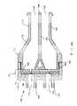
- a longitudinal sectional view of the internal lumens of the valve assembly 100is generally in a “Y” configuration to bring the two separated fluid flows into closely parallel extrusion conduits. It can be readily appreciated that other types of lumen configurations are also within the scope of the present invention.
- the internal lumens of a pressure responsive slit valve assemblyis generally configured to correspond to and accommodate the shape of the valve housing, the location of the apertures and the design of the extrusion stems.
- valve housing 105can be manufactured and assembled in different ways to accommodate the desired configuration and the selected material of the valve housing.
- the valve housing 105can be formed from a female part 178 , and a male part 182 .
- the female part 178can generally include the first and second apertures 112 and 114 , and two connection ports 120 and 122 .
- the male part 182can generally include the first and second extrusion stems 158 and 162 , and the internal walls 154 .
- the male and female parts 178 and 182are constructed such that one sealingly connects to the other.
- the female part 178can have a relatively larger annular wall with internal threads 186 .
- the male part 182can have a relatively smaller annular wall with external threads 190 .
- the male part 182can frictionally fit into the female part 178 such that the internal threads 186 and the external threads 190 can interact with each other to generate frictional forces.
- an adhesivecan be used to secure a bond between the female part 178 and the male part 182 .
- a female part 178 and a male part 182can be thermally, chemically, mechanically or ionically bonded together.
- the slit valve means 110 of the pressure responsive slit valve assembly 100generally includes a first slit 192 and a second slit 193 .
- the first slit 192is disposed transversely between and in communication with the first conduit 146 and the first aperture 112 . Accordingly, the first slit 192 is responsive to a pressure differential associated with the first fluid.
- the first slit 192remains in a closed position until a pressure differential having a predetermined force exists across the first slit 192 . Once the pressure differential crosses over this predetermined force threshold, the first slit 192 deforms, thereby allowing the first fluid to flow therethrough in a desired direction.
- the second slit 193is disposed transversely between and in communication with the second conduit 150 and the second aperture 114 . Accordingly, the second slit is responsive to a pressure differential associated with the second fluid. In particular, the second slit 193 remains in a closed position until a pressure differential having a predetermined force exists across the second slit 193 . Once the pressure differential crosses over this predetermined force threshold, the second slit 193 deforms, thereby allowing the second fluid to flow therethrough in a desired direction.
- Both slits 192 and 193may be straight-cut slits. In some embodiments slits 192 and 193 maybe H-shaped as shown in FIG. 6 . Alternatively, slits 192 and 193 may have a saw-tooth wave shape as shown in FIG. 7 . Other suitable shaped slits are within the scope of the present invention.
- the slit valve means 110includes one elastomeric, thin diaphragm 195 that defines both the first and second slits 192 and 193 .
- the elastomeric, thin diaphragm 195is preferably made from silicone or other flexible materials. It is also contemplated that the diaphragm materials can be reinforced if desirable. For example, wires or fiber braids can be incorporated into the silicone or other flexible materials to reinforce the diaphragm 195 .
- the shape of the diaphragm 195 and the shape of the valve housing 105generally accommodate each other. Accordingly, suitable shapes for the diaphragm 195 include, but are not limited to, disc shape, rectangular shape, or overlapped double circle shape, or other suitable shapes.
- the slit valve means 110further includes slit valve securement means adjacent the periphery of the slit valve means.
- the slit valve securement meansincludes diaphragm securement members 197 and 199 , each of which is disposed at one side of the diaphragm 195 .
- Each diaphragm securement members 197 and 199defines two apertures, each of which is centrally aligned with its corresponding slit on the diaphragm 195 so that the fluids can get across the slits.
- Diaphragm securement members 197 and 199are preferably rigid, and can be formed of synthetic resinous materials. Under the assembled condition, as can be seen in FIG.
- the slit valve means 110can be sandwiched between the female part 178 and the male part 182 of the valve housing 105 .
- the diaphragm securement members 197 and 199compressively support the elastomeric diaphragm 195 except to permit the first and second slits 192 and 193 on the diaphragm 195 to flex depending on pressure differential conditions associated with the first and second fluids, respectively.
- the valve assembly 200comprises a slit valve means 210 that includes two separate elastomeric, thin diaphragms, a first diaphragm 220 defining the first slit 225 , and a second diaphragm 230 defining the second slit 235 .
- Both first and second diaphragms 220 and 230are preferably made from silicone or other flexible materials. It is also contemplated that the diaphragm materials can be reinforced if desirable. For example, wires or fiber braids can be incorporated into the silicone or other flexible materials to reinforce the diaphragms 220 and 230 .
- the first diaphragm 220is disposed transversely between the first aperture 212 and the first conduit 246 such that the first slit 225 is responsive to a pressure differential associated with the first fluid.
- the first slit 225remains in a closed position until a pressure differential having a predetermined force exists across the first slit 225 . Once the pressure differential crosses over this predetermined force threshold, the first slit 225 deforms, thereby allowing the first fluid to flow therethrough in a desired direction.
- the second diaphragm 230is disposed transversely between the second aperture 214 and the second conduit 250 such that the second slit 235 is responsive to a pressure differential associated with the second fluid.
- the second slit 235remains in a closed position until a pressure differential having a predetermined force exists across the second slit 235 . Once the pressure differential crosses over this predetermined force threshold, the second slit 235 deforms, thereby allowing the second fluid to flow therethrough in a desired direction.
- Both slits 225 and 235may be straight-cut slits, H-shaped slits, saw-tooth wave shaped slits, or other suitable shaped slits.
- first and second diaphragms 220 and 230 and the shape of the valve housing 205generally accommodate one another. Accordingly, suitable shapes for the first and second diaphragms 220 and 230 include, but are not limited to, disc shape, rectangular shape, or other suitable shapes.
- the slit valve means 210further comprises slit valve securement means adjacent the periphery of the slit valve means.
- the slit valve securement meansincludes diaphragm securement members 240 and 242 disposed at each side of the first diaphragm 220 , and diaphragm securement members 244 and 248 disposed at each side of the second diaphragm 230 .
- Each diaphragm securement members 240 and 242defines one aperture that is centrally aligned with the first slit 225 so that the first fluid can get across the first slit 225 .
- each diaphragm securement member 244 and 248defines one aperture that is centrally aligned with the second slit 235 so that the second fluid can get across the second slit 235 .
- All of the diaphragm securement members 240 , 242 , 244 , and 248are preferably rigid, and can be formed of synthetic resinous materials.
- valve housing 205can be modified in many different ways to accommodate the configuration of two separated diaphragms.
- the valve housing 205can further include an additional wall 252 to separate, as well as to support the first and second diaphragms 220 and 230 .
- the wall 252can perpendicularly join to the interior surface of the vertical wall 216 .
- the wall 252can integrally join the internal walls 254 in the valve housing 205 . Accordingly, under the assembled condition, as can be seen in FIG.
- the diaphragm securement members 240 and 242compressively support the first elastomeric diaphragm 220 while permit the first slit 225 to flex depending on pressure differential conditions associated with the first fluid.
- the diaphragm securement members 244 and 248compressively support the second elastomeric diaphragm 230 while permit the second slit 235 to flex depending on pressure differential conditions associated with the second fluid.
- a slit valve meansmay be disposed transversely anywhere between the first and second apertures and the first and second conduits. In the embodiments that a slit valve means is not disposed adjacent to the apertures, it is within the skill of an ordinary artisan in the field to modify the valve housing accordingly to accommodate the placement of the slit valve means.
- a pressure responsive slit valve assembly of the present inventioncan be incorporated into multi-lumen or dual-lumen PICC catheters, multi-lumen or dual-lumen tunneled central venous catheters, and multi-lumen or dual-lumen dialysis catheters.
- a dual-lumen valve assembly of the present inventioncan be incorporated into the currently-used V-connector in a dual-lumen PICC catheter. Further more, incorporation of the present invention permits a proximally trimmable PICC catheter.
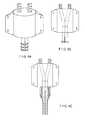
- FIG. 8Aa perspective view of an exemplary embodiment of a pressure responsive slit valve assembly adapted for use with a PICC catheter is shown in FIG. 8A
- FIG. 8Ba schematic view of an exemplary embodiment of a pressure responsive slit valve assembly adapted for use with a PICC catheter is shown in FIG. 8B
- FIG. 8Ca schematic view of an exemplary embodiment of a pressure responsive slit valve assembly with a dual-lumen PICC catheter attached thereon is shown in FIG. 8C .
- the valve assemblyoptionally comprises suture wings with suture holes thereon, and barbs or lure threads on the exterior surfaces of connection ports and extrusion stems. It can be readily appreciated by one of skill in the art that the numbers and the configurations of the suture wings, suture holes, barbs and lure threads can be modified in many different ways to accommodate a desired configuration of a catheter.
- a pressure responsive slit valve assembly of the present inventioncan be configured to communicate with more than two fluid sources.
- a valve housingcan be further adapted to receive one additional fluid from an additional source.
- the valve housingcan define at least one additional aperture and at least one additional corresponding conduit.
- the slit valve meanscan also include at least one additional pressure responsive slit corresponding with the additional fluid source.
- FIG. 9a perspective view of a triple-cavity pressure responsive slit valve assembly is shown in FIG. 9 .
- FIG. 10One exemplary embodiment of the triple cavity pressure responsive slit valve is shown in FIG. 10 .
- a triple cavity slit valve assembly 300is shown in a perspective view with selected internal passages shown in dashed lines.
- three apertures 302 , 304 , 306 at one end of the valve assembly 300correspond to three conduits on the opposite end.
- one of the additional corresponding apertures 302is connected by a flow passage 316 of the valve assembly 300 to a corresponding additional conduit 310 of the extrusion stem 308 .
- the operation of the triple cavity valve assembly 300is analogous to the operation of the valves according to the invention described above.
- kits of the present inventionprovide a kit for adapting a medical device to accommodate a plurality of fluids.
- a kit of the present inventiontypically includes a pressure responsive slit valve assembly that is adapted for connecting to a desired medical device to receive fluids from at least two sources.
- the assemblytypically comprises a slit valve means corresponding to each fluid source.
- a kit of the present inventionmay further include securement means for securely adapting the pressure responsive slit valve assembly to a desired medical device.
Landscapes
- Health & Medical Sciences (AREA)
- Heart & Thoracic Surgery (AREA)
- Hematology (AREA)
- Engineering & Computer Science (AREA)
- Anesthesiology (AREA)
- Biomedical Technology (AREA)
- Life Sciences & Earth Sciences (AREA)
- Animal Behavior & Ethology (AREA)
- General Health & Medical Sciences (AREA)
- Public Health (AREA)
- Veterinary Medicine (AREA)
- Pulmonology (AREA)
- Vascular Medicine (AREA)
- Infusion, Injection, And Reservoir Apparatuses (AREA)
Abstract
Description
Claims (6)
Priority Applications (1)
| Application Number | Priority Date | Filing Date | Title |
|---|---|---|---|
| US13/165,286US8679074B2 (en) | 2003-03-18 | 2011-06-21 | Pressure responsive slit valve assembly for a plurality of fluids and uses thereof |
Applications Claiming Priority (2)
| Application Number | Priority Date | Filing Date | Title |
|---|---|---|---|
| US10/390,854US7988679B2 (en) | 2003-03-18 | 2003-03-18 | Pressure responsive slit valve assembly for a plurality of fluids and uses thereof |
| US13/165,286US8679074B2 (en) | 2003-03-18 | 2011-06-21 | Pressure responsive slit valve assembly for a plurality of fluids and uses thereof |
Related Parent Applications (1)
| Application Number | Title | Priority Date | Filing Date |
|---|---|---|---|
| US10/390,854ContinuationUS7988679B2 (en) | 2003-03-18 | 2003-03-18 | Pressure responsive slit valve assembly for a plurality of fluids and uses thereof |
Publications (2)
| Publication Number | Publication Date |
|---|---|
| US20110313367A1 US20110313367A1 (en) | 2011-12-22 |
| US8679074B2true US8679074B2 (en) | 2014-03-25 |
Family
ID=32987589
Family Applications (2)
| Application Number | Title | Priority Date | Filing Date |
|---|---|---|---|
| US10/390,854Expired - Fee RelatedUS7988679B2 (en) | 2003-03-18 | 2003-03-18 | Pressure responsive slit valve assembly for a plurality of fluids and uses thereof |
| US13/165,286Expired - Fee RelatedUS8679074B2 (en) | 2003-03-18 | 2011-06-21 | Pressure responsive slit valve assembly for a plurality of fluids and uses thereof |
Family Applications Before (1)
| Application Number | Title | Priority Date | Filing Date |
|---|---|---|---|
| US10/390,854Expired - Fee RelatedUS7988679B2 (en) | 2003-03-18 | 2003-03-18 | Pressure responsive slit valve assembly for a plurality of fluids and uses thereof |
Country Status (3)
| Country | Link |
|---|---|
| US (2) | US7988679B2 (en) |
| EP (1) | EP1603632A1 (en) |
| WO (1) | WO2004082757A1 (en) |
Cited By (6)
| Publication number | Priority date | Publication date | Assignee | Title |
|---|---|---|---|---|
| US9895524B2 (en) | 2012-07-13 | 2018-02-20 | Angiodynamics, Inc. | Fluid bypass device for valved catheters |
| US10610678B2 (en) | 2016-08-11 | 2020-04-07 | Angiodynamics, Inc. | Bi-directional, pressure-actuated medical valve with improved fluid flow control and method of using such |
| US10737085B2 (en) | 2017-05-05 | 2020-08-11 | Greatbatch Ltd. | Medical device with hemostatic valve |
| US11612734B2 (en) | 2009-07-13 | 2023-03-28 | Angiodynamics, Inc. | Method to secure an elastic component in a valve |
| US11628243B2 (en) | 2003-06-27 | 2023-04-18 | Angiodynamics, Inc. | Pressure actuated valve with improved biasing member |
| US11679248B2 (en) | 2008-05-21 | 2023-06-20 | Angiodynamics, Inc. | Pressure activated valve for high flow rate and pressure venous access applications |
Families Citing this family (89)
| Publication number | Priority date | Publication date | Assignee | Title |
|---|---|---|---|---|
| US8177762B2 (en) | 1998-12-07 | 2012-05-15 | C. R. Bard, Inc. | Septum including at least one identifiable feature, access ports including same, and related methods |
| US6440164B1 (en) | 1999-10-21 | 2002-08-27 | Scimed Life Systems, Inc. | Implantable prosthetic valve |
| US6602286B1 (en) | 2000-10-26 | 2003-08-05 | Ernst Peter Strecker | Implantable valve system |
| US20070161970A1 (en)* | 2004-04-16 | 2007-07-12 | Medrad, Inc. | Fluid Delivery System, Fluid Path Set, and Pressure Isolation Mechanism with Hemodynamic Pressure Dampening Correction |
| US6752828B2 (en) | 2002-04-03 | 2004-06-22 | Scimed Life Systems, Inc. | Artificial valve |
| US7007698B2 (en) | 2002-04-03 | 2006-03-07 | Boston Scientific Corporation | Body lumen closure |
| AU2003285943B2 (en) | 2002-10-24 | 2008-08-21 | Boston Scientific Limited | Venous valve apparatus and method |
| US6969381B2 (en)* | 2002-12-18 | 2005-11-29 | Medical Components, Inc. | Multi-lumen catheter with detachable locking hub |
| US6945957B2 (en) | 2002-12-30 | 2005-09-20 | Scimed Life Systems, Inc. | Valve treatment catheter and methods |
| US7988679B2 (en) | 2003-03-18 | 2011-08-02 | Navilyst Medical, Inc. | Pressure responsive slit valve assembly for a plurality of fluids and uses thereof |
| US7951121B2 (en)* | 2003-07-30 | 2011-05-31 | Navilyst Medical, Inc. | Pressure actuated valve with improved slit configuration |
| CA2536368A1 (en)* | 2003-08-19 | 2005-03-03 | Nmt Medical, Inc. | Expandable sheath tubing |
| US7252652B2 (en)* | 2003-08-29 | 2007-08-07 | Boston Scientific Scimed, Inc. | Valved catheters including high flow rate catheters |
| US8128681B2 (en) | 2003-12-19 | 2012-03-06 | Boston Scientific Scimed, Inc. | Venous valve apparatus, system, and method |
| US7854761B2 (en) | 2003-12-19 | 2010-12-21 | Boston Scientific Scimed, Inc. | Methods for venous valve replacement with a catheter |
| US8187234B2 (en) | 2004-01-29 | 2012-05-29 | Navilyst Medical, Inc. | Pressure activated safety valve with anti-adherent coating |
| US8034035B2 (en) | 2004-01-29 | 2011-10-11 | Navilyst Medical, Inc. | Pressure activated safety valve with high flow slit |
| US9933079B2 (en) | 2004-01-29 | 2018-04-03 | Angiodynamics, Inc. | Stacked membrane for pressure actuated valve |
| US8267915B2 (en)* | 2004-01-29 | 2012-09-18 | Navilyst Medical, Inc. | Dual well port device |
| US8083728B2 (en) | 2004-03-18 | 2011-12-27 | C. R. Bard, Inc. | Multifunction adaptor for an open-ended catheter |
| US7854731B2 (en) | 2004-03-18 | 2010-12-21 | C. R. Bard, Inc. | Valved catheter |
| US7578803B2 (en) | 2004-03-18 | 2009-08-25 | C. R. Bard, Inc. | Multifunction adaptor for an open-ended catheter |
| US7094218B2 (en) | 2004-03-18 | 2006-08-22 | C. R. Bard, Inc. | Valved catheter |
| US7594911B2 (en) | 2004-03-18 | 2009-09-29 | C. R. Bard, Inc. | Connector system for a proximally trimmable catheter |
| US7594910B2 (en) | 2004-03-18 | 2009-09-29 | C. R. Bard, Inc. | Catheter connector |
| US7377915B2 (en) | 2004-04-01 | 2008-05-27 | C. R. Bard, Inc. | Catheter connector system |
| EP1740253B1 (en) | 2004-04-30 | 2008-08-13 | C.R.Bard, Inc. | Valved sheath introducer for venous cannulation |
| US7566343B2 (en) | 2004-09-02 | 2009-07-28 | Boston Scientific Scimed, Inc. | Cardiac valve, system, and method |
| US8403890B2 (en) | 2004-11-29 | 2013-03-26 | C. R. Bard, Inc. | Reduced friction catheter introducer and method of manufacturing and using the same |
| US8932260B2 (en) | 2004-11-29 | 2015-01-13 | C. R. Bard, Inc. | Reduced-friction catheter introducer and method of manufacturing and using the same |
| US9597483B2 (en) | 2004-11-29 | 2017-03-21 | C. R. Bard, Inc. | Reduced-friction catheter introducer and method of manufacturing and using the same |
| US8926564B2 (en) | 2004-11-29 | 2015-01-06 | C. R. Bard, Inc. | Catheter introducer including a valve and valve actuator |
| US7854755B2 (en) | 2005-02-01 | 2010-12-21 | Boston Scientific Scimed, Inc. | Vascular catheter, system, and method |
| US20060173490A1 (en) | 2005-02-01 | 2006-08-03 | Boston Scientific Scimed, Inc. | Filter system and method |
| US7878966B2 (en) | 2005-02-04 | 2011-02-01 | Boston Scientific Scimed, Inc. | Ventricular assist and support device |
| US7780722B2 (en) | 2005-02-07 | 2010-08-24 | Boston Scientific Scimed, Inc. | Venous valve apparatus, system, and method |
| US7670368B2 (en) | 2005-02-07 | 2010-03-02 | Boston Scientific Scimed, Inc. | Venous valve apparatus, system, and method |
| US8328768B2 (en) | 2005-02-11 | 2012-12-11 | Angiodynamics, Inc | Pressure activated safety valve with improved flow characteristics and durability |
| US7867274B2 (en) | 2005-02-23 | 2011-01-11 | Boston Scientific Scimed, Inc. | Valve apparatus, system and method |
| US8029482B2 (en) | 2005-03-04 | 2011-10-04 | C. R. Bard, Inc. | Systems and methods for radiographically identifying an access port |
| US9474888B2 (en) | 2005-03-04 | 2016-10-25 | C. R. Bard, Inc. | Implantable access port including a sandwiched radiopaque insert |
| US7947022B2 (en) | 2005-03-04 | 2011-05-24 | C. R. Bard, Inc. | Access port identification systems and methods |
| JP5484674B2 (en) | 2005-03-04 | 2014-05-07 | シー・アール・バード・インコーポレーテッド | Access port and identification method |
| US7722666B2 (en) | 2005-04-15 | 2010-05-25 | Boston Scientific Scimed, Inc. | Valve apparatus, system and method |
| EP1874393B1 (en) | 2005-04-27 | 2017-09-06 | C.R.Bard, Inc. | Infusion apparatuses |
| US10307581B2 (en) | 2005-04-27 | 2019-06-04 | C. R. Bard, Inc. | Reinforced septum for an implantable medical device |
| EP3884989B1 (en) | 2005-04-27 | 2022-07-13 | C. R. Bard, Inc. | Vascular access port |
| US8012198B2 (en) | 2005-06-10 | 2011-09-06 | Boston Scientific Scimed, Inc. | Venous valve, system, and method |
| US7875019B2 (en) | 2005-06-20 | 2011-01-25 | C. R. Bard, Inc. | Connection system for multi-lumen catheter |
| US7901395B2 (en)* | 2005-08-16 | 2011-03-08 | Borden Jonathan R | Catheter having staggered lumens and method |
| US7569071B2 (en) | 2005-09-21 | 2009-08-04 | Boston Scientific Scimed, Inc. | Venous valve, system, and method with sinus pocket |
| CA2626335C (en) | 2005-12-02 | 2013-11-05 | C.R. Bard, Inc. | Pressure-activated proximal valves |
| US7799038B2 (en) | 2006-01-20 | 2010-09-21 | Boston Scientific Scimed, Inc. | Translumenal apparatus, system, and method |
| US8585660B2 (en) | 2006-01-25 | 2013-11-19 | Navilyst Medical, Inc. | Valved catheter with power injection bypass |
| US8062269B2 (en) | 2006-06-09 | 2011-11-22 | Baxter International Inc. | Fail safe dual chamber peritoneal dialysis/infusion system |
| US9265912B2 (en) | 2006-11-08 | 2016-02-23 | C. R. Bard, Inc. | Indicia informative of characteristics of insertable medical devices |
| US9642986B2 (en) | 2006-11-08 | 2017-05-09 | C. R. Bard, Inc. | Resource information key for an insertable medical device |
| WO2008091493A1 (en) | 2007-01-08 | 2008-07-31 | California Institute Of Technology | In-situ formation of a valve |
| US7967853B2 (en) | 2007-02-05 | 2011-06-28 | Boston Scientific Scimed, Inc. | Percutaneous valve, system and method |
| DE102007028184A1 (en)* | 2007-06-20 | 2008-12-24 | Braun Gmbh | Brush head for a toothbrush |
| US8828079B2 (en) | 2007-07-26 | 2014-09-09 | Boston Scientific Scimed, Inc. | Circulatory valve, system and method |
| US8608702B2 (en) | 2007-10-19 | 2013-12-17 | C. R. Bard, Inc. | Introducer including shaped distal region |
| US9579496B2 (en) | 2007-11-07 | 2017-02-28 | C. R. Bard, Inc. | Radiopaque and septum-based indicators for a multi-lumen implantable port |
| US7892276B2 (en) | 2007-12-21 | 2011-02-22 | Boston Scientific Scimed, Inc. | Valve with delayed leaflet deployment |
| US8075536B2 (en)* | 2008-09-09 | 2011-12-13 | Navilyst Medical, Inc. | Power injectable port identification |
| ES2906416T3 (en) | 2008-10-31 | 2022-04-18 | Bard Inc C R | Systems and methods to identify an access road |
| US11890443B2 (en) | 2008-11-13 | 2024-02-06 | C. R. Bard, Inc. | Implantable medical devices including septum-based indicators |
| US8932271B2 (en) | 2008-11-13 | 2015-01-13 | C. R. Bard, Inc. | Implantable medical devices including septum-based indicators |
| US8337470B2 (en) | 2009-01-28 | 2012-12-25 | Angiodynamics, Inc. | Three-way valve for power injection in vascular access devices |
| US8083721B2 (en) | 2009-01-29 | 2011-12-27 | Navilyst Medical, Inc. | Power injection valve |
| US8449459B2 (en)* | 2009-03-31 | 2013-05-28 | Covidien Lp | Access portal including silicone foam three layer seal |
| WO2010151825A1 (en) | 2009-06-26 | 2010-12-29 | C. R. Bard, Inc. | Proximally trimmable catheter including pre-attached bifurcation and related methods |
| US8623028B2 (en) | 2009-09-23 | 2014-01-07 | Intuitive Surgical Operations, Inc. | Surgical port feature |
| US8888789B2 (en) | 2009-09-23 | 2014-11-18 | Intuitive Surgical Operations, Inc. | Curved cannula surgical system control |
| US20110071541A1 (en) | 2009-09-23 | 2011-03-24 | Intuitive Surgical, Inc. | Curved cannula |
| US8465476B2 (en)* | 2009-09-23 | 2013-06-18 | Intuitive Surgical Operations, Inc. | Cannula mounting fixture |
| US8545515B2 (en) | 2009-09-23 | 2013-10-01 | Intuitive Surgical Operations, Inc. | Curved cannula surgical system |
| ES2695907T3 (en) | 2009-11-17 | 2019-01-11 | Bard Inc C R | Overmolded access port that includes anchoring and identification features |
| USD676955S1 (en) | 2010-12-30 | 2013-02-26 | C. R. Bard, Inc. | Implantable access port |
| USD682416S1 (en) | 2010-12-30 | 2013-05-14 | C. R. Bard, Inc. | Implantable access port |
| US9668859B2 (en) | 2011-08-05 | 2017-06-06 | California Institute Of Technology | Percutaneous heart valve delivery systems |
| WO2014144247A1 (en) | 2013-03-15 | 2014-09-18 | Arash Kheradvar | Handle mechanism and functionality for repositioning and retrieval of transcatheter heart valves |
| EP3378525B1 (en)* | 2013-03-16 | 2019-08-28 | Poly Medicure Limited | Transfer device valve |
| EP3215211A4 (en) | 2014-11-07 | 2018-07-04 | C. R. Bard, Inc. | Connection system for tunneled catheters |
| WO2018025094A1 (en) | 2016-08-01 | 2018-02-08 | Poly Medicure Limited | Intravenous catheter apparatus with safety function and pressure controlled valve element |
| US11896782B2 (en) | 2017-08-23 | 2024-02-13 | C. R. Bard, Inc. | Priming and tunneling system for a retrograde catheter assembly |
| CA3091601A1 (en) | 2019-09-18 | 2021-03-18 | Heraeus Medical Gmbh | Device for temporarily, locally applying fluids |
| EP3795196B1 (en) | 2019-09-18 | 2022-05-11 | Heraeus Medical GmbH | Device for temporary local application of fluids |
| USD1052047S1 (en) | 2022-02-11 | 2024-11-19 | Joseph Richard Cant | Valve for a nozzle |
Citations (162)
| Publication number | Priority date | Publication date | Assignee | Title |
|---|---|---|---|---|
| US2446571A (en) | 1944-03-02 | 1948-08-10 | American Brake Shoe Co | Check valve |
| US2720881A (en) | 1953-06-08 | 1955-10-18 | Jones John Leslie | Closure |
| US2755060A (en) | 1951-12-03 | 1956-07-17 | Twyman L Raymond | Reinforced flexible wall valve structure |
| US3113586A (en) | 1962-09-17 | 1963-12-10 | Physio Control Company Inc | Artificial heart valve |
| GB966137A (en) | 1959-10-27 | 1964-08-06 | Girling Ltd | Fluid flow control means |
| US3159175A (en) | 1961-12-12 | 1964-12-01 | Delman Co | Fluid check valve unit |
| US3159176A (en) | 1962-12-07 | 1964-12-01 | Vernay Laboratories | Check-relief valve |
| US3477438A (en) | 1967-04-17 | 1969-11-11 | Dwight L Allen | Catheter having one-way inflations valve |
| US3514438A (en) | 1969-06-06 | 1970-05-26 | Amicon Corp | Antithrombogenic materials |
| US3525357A (en) | 1968-11-18 | 1970-08-25 | Waters Co The | Pump valve apparatus |
| US3621557A (en) | 1969-06-06 | 1971-11-23 | Rex Chainbelt Inc | Insert for sandwich panels and method of installation |
| US3669323A (en) | 1969-12-12 | 1972-06-13 | American Can Co | One-way valve insert for collapsible dispensing containers |
| US3674183A (en) | 1971-02-01 | 1972-07-04 | Herny B Venable | Dispensing device |
| US3673612A (en) | 1970-08-28 | 1972-07-04 | Massachusetts Inst Technology | Non-thrombogenic materials and methods for their preparation |
| US3710942A (en) | 1967-06-02 | 1973-01-16 | Pall Corp | Valve for fluid lines and structures containing the same |
| US3788327A (en) | 1971-03-30 | 1974-01-29 | H Donowitz | Surgical implant device |
| US3811466A (en) | 1972-04-06 | 1974-05-21 | J Ohringer | Slit diaphragm valve |
| US3941149A (en) | 1974-11-11 | 1976-03-02 | Baxter Laboratories, Inc. | Valve |
| US3955594A (en) | 1974-02-25 | 1976-05-11 | Raymond International Inc. | Pressure operated valve systems |
| US4072146A (en) | 1976-09-08 | 1978-02-07 | Howes Randolph M | Venous catheter device |
| US4142525A (en) | 1977-03-10 | 1979-03-06 | The Kendall Company | Syringe assembly |
| US4143853A (en) | 1977-07-14 | 1979-03-13 | Metatech Corporation | Valve for use with a catheter or the like |
| US4244379A (en) | 1979-08-02 | 1981-01-13 | Quest Medical, Inc. | Check valve for blood drawing apparatus |
| FR2508008A1 (en) | 1981-06-17 | 1982-12-24 | Otk Keskusosuusliike | FLUID DISPENSER WITH SPOUT |
| US4387879A (en) | 1978-04-19 | 1983-06-14 | Eduard Fresenius Chemisch Pharmazeutische Industrie Kg | Self-sealing connector for use with plastic cannulas and vessel catheters |
| US4405316A (en) | 1978-04-03 | 1983-09-20 | Baxter Travenol Laboratories, Inc. | Injection site with check valve inlet |
| US4417888A (en)* | 1982-03-15 | 1983-11-29 | Renal Systems, Inc. | Percutaneous implant |
| US4434810A (en) | 1980-07-14 | 1984-03-06 | Vernay Laboratories, Inc. | Bi-directional pressure relief valve |
| US4447237A (en)* | 1982-05-07 | 1984-05-08 | Dow Corning Corporation | Valving slit construction and cooperating assembly for penetrating the same |
| US4468224A (en) | 1982-01-28 | 1984-08-28 | Advanced Cardiovascular Systems, Inc. | System and method for catheter placement in blood vessels of a human patient |
| EP0128625A1 (en) | 1983-06-13 | 1984-12-19 | Koninklijke Philips Electronics N.V. | Magnetic transducing head for writing information on high-coercive recording media |
| US4502502A (en) | 1982-09-22 | 1985-03-05 | C. R. Bard, Inc. | Overpressure safety valve |
| US4524805A (en) | 1983-07-08 | 1985-06-25 | Hoffman Allan C | Normally closed duckbill valve and method of manufacture |
| US4543087A (en) | 1983-11-14 | 1985-09-24 | Quinton Instrument Company | Double lumen catheter tip |
| US4552553A (en) | 1983-06-30 | 1985-11-12 | Pudenz-Schulte Medical Research Corp. | Flow control valve |
| US4610665A (en) | 1983-01-18 | 1986-09-09 | Terumo Kabushiki Kaisha | Medical instrument |
| US4616768A (en) | 1983-06-07 | 1986-10-14 | Lingner & Fischer Gmbh | Discharge barrier for collapsible tubes |
| US4646945A (en) | 1985-06-28 | 1987-03-03 | Steiner Company, Inc. | Vented discharge assembly for liquid soap dispenser |
| US4673393A (en) | 1984-12-28 | 1987-06-16 | Terumo Kabushiki Kaisha | Medical instrument |
| US4681572A (en) | 1982-09-13 | 1987-07-21 | Hollister Incorporated | Female urinary incontinence device |
| US4692146A (en) | 1985-10-24 | 1987-09-08 | Cormed, Inc. | Multiple vascular access port |
| US4722725A (en) | 1983-04-12 | 1988-02-02 | Interface Biomedical Laboratories, Inc. | Methods for preventing the introduction of air or fluid into the body of a patient |
| US4790832A (en)* | 1986-06-06 | 1988-12-13 | Icu Medical, Inc. | System for administering medication nasally to a patient |
| US4798594A (en) | 1987-09-21 | 1989-01-17 | Cordis Corporation | Medical instrument valve |
| US4801297A (en) | 1984-06-01 | 1989-01-31 | Edward Weck Incorporated | Catheter having slit tip |
| EP0337617A2 (en) | 1988-04-12 | 1989-10-18 | H.G. Wallace Limited | Pressure actuated valve particularly for biological use |
| US4908028A (en) | 1987-03-20 | 1990-03-13 | Jean Colon | Valve incorporating at least one rocking flap with respect to elastic pivots |
| US4944726A (en) | 1988-11-03 | 1990-07-31 | Applied Vascular Devices | Device for power injection of fluids |
| US4946448A (en) | 1989-10-23 | 1990-08-07 | Kendall Mcgaw Laboratories, Inc. | Check valve for use with intravenous pump |
| US4960412A (en) | 1988-04-15 | 1990-10-02 | Universal Medical Instrument Corp. | Catheter introducing system |
| US5000745A (en) | 1988-11-18 | 1991-03-19 | Edward Weck Incorporated | Hemostatis valve |
| US5009391A (en) | 1988-05-02 | 1991-04-23 | The Kendall Company | Valve assembly |
| US5030210A (en) | 1988-02-08 | 1991-07-09 | Becton, Dickinson And Company | Catheter valve assembly |
| US5084015A (en) | 1988-05-16 | 1992-01-28 | Terumo Kabushiki Kaisha | Catheter assembly of the hypodermic embedment type |
| US5098405A (en) | 1991-01-31 | 1992-03-24 | Becton, Dickinson And Company | Apparatus and method for a side port cathether adapter with a one piece integral combination valve |
| US5125893A (en) | 1990-04-16 | 1992-06-30 | Dryden Gale E | Suction catheter with wall lumen for irrigation |
| US5147332A (en) | 1991-05-17 | 1992-09-15 | C.R. Bard, Inc. | Multi-valve catheter for improved reliability |
| US5149327A (en) | 1989-09-05 | 1992-09-22 | Terumo Kabushiki Kaisha | Medical valve, catheter with valve, and catheter assembly |
| US5167638A (en) | 1989-10-27 | 1992-12-01 | C. R. Bard, Inc. | Subcutaneous multiple-access port |
| US5169393A (en) | 1990-09-04 | 1992-12-08 | Robert Moorehead | Two-way outdwelling slit valving of medical liquid flow through a cannula and methods |
| US5176662A (en) | 1990-08-23 | 1993-01-05 | Minimed Technologies, Ltd. | Subcutaneous injection set with improved cannula mounting arrangement |
| US5176652A (en) | 1989-12-22 | 1993-01-05 | Cordis Corporation | Hemostasis valve |
| US5201722A (en) | 1990-09-04 | 1993-04-13 | Moorehead Robert H | Two-way outdwelling slit valving of medical liquid flow through a cannula and methods |
| US5205834A (en) | 1990-09-04 | 1993-04-27 | Moorehead H Robert | Two-way outdwelling slit valving of medical liquid flow through a cannula and methods |
| US5249598A (en) | 1992-08-03 | 1993-10-05 | Vernay Laboratories, Inc. | Bi-directional vent and overpressure relief valve |
| US5254086A (en) | 1992-07-31 | 1993-10-19 | Ballard Medical Products | Medical lavage apparatus and methods |
| US5324274A (en) | 1992-03-30 | 1994-06-28 | Med-Pro Design, Inc. | Catheter having rotary valves |
| US5336203A (en) | 1993-05-28 | 1994-08-09 | Abbott Laboratories | Low profile gastrostomy device with dome |
| US5360407A (en) | 1991-08-29 | 1994-11-01 | C. R. Bard, Inc. | Implantable dual access port with tactile ridge for position sensing |
| US5370624A (en) | 1993-09-14 | 1994-12-06 | Becton Dickinson And Company | Catheter with deactivatable side port |
| US5395352A (en) | 1992-02-24 | 1995-03-07 | Scimed Lift Systems, Inc. | Y-adaptor manifold with pinch valve for an intravascular catheter |
| US5396925A (en) | 1993-12-16 | 1995-03-14 | Abbott Laboratories | Anti-free flow valve, enabling fluid flow as a function of pressure and selectively opened to enable free flow |
| US5399168A (en) | 1991-08-29 | 1995-03-21 | C. R. Bard, Inc. | Implantable plural fluid cavity port |
| US5401255A (en) | 1993-07-20 | 1995-03-28 | Baxter International Inc. | Multi-functional valve with unitary valving member and improved safety |
| US5405340A (en) | 1992-10-07 | 1995-04-11 | Abbott Laboratories | Threaded securing apparatus for flow connectors |
| USD357735S (en) | 1993-08-03 | 1995-04-25 | I-Flow Corporation | Valve for filling an IV solution bag |
| US5411491A (en) | 1993-05-28 | 1995-05-02 | Abbott Laboratories | Low profile gastrostomy device with one-way cross-slit valve |
| US5453097A (en)* | 1994-08-15 | 1995-09-26 | Paradis; Joseph R. | Control of fluid flow |
| US5454784A (en) | 1994-06-10 | 1995-10-03 | Zimmer, Inc. | Control valve for a fluid set |
| US5470305A (en) | 1993-04-19 | 1995-11-28 | Stryker Corporation | Irrigation handpiece with built in pulsing pump |
| US5469805A (en) | 1992-08-22 | 1995-11-28 | Keystone International Holdings Corp. | High visibility valve position indicator |
| US5484420A (en) | 1992-07-09 | 1996-01-16 | Wilson-Cook Medical Inc. | Retention bolsters for percutaneous catheters |
| FR2718969B1 (en) | 1994-04-21 | 1996-07-12 | Balt Extrusion | Safety device for catheter, against overpressure during injection of product. |
| US5542923A (en) | 1990-03-01 | 1996-08-06 | Michigan Transtech Corporation | Implantable access devices |
| US5545150A (en) | 1994-05-06 | 1996-08-13 | Endoscopic Concepts, Inc. | Trocar |
| US5554136A (en) | 1994-09-07 | 1996-09-10 | Luther Medical Products, Inc. | Dual lumen infusion/aspiration catheter |
| US5562618A (en) | 1994-01-21 | 1996-10-08 | Sims Deltec, Inc. | Portal assembly and catheter connector |
| US5571093A (en)* | 1994-09-21 | 1996-11-05 | Cruz; Cosme | Multiple-lumen catheter |
| US5575769A (en) | 1995-05-30 | 1996-11-19 | Vaillancourt; Vincent L. | Cannula for a slit septum and a lock arrangement therefore |
| US5624395A (en) | 1995-02-23 | 1997-04-29 | Cv Dynamics, Inc. | Urinary catheter having palpitatable valve and balloon and method for making same |
| US5637099A (en) | 1994-06-09 | 1997-06-10 | Durdin; Daniel J. | Needle handling apparatus and methods |
| US5743884A (en) | 1992-12-17 | 1998-04-28 | Hasson; Harrith M. | Sealing structure for medical instrument |
| US5743894A (en) | 1995-06-07 | 1998-04-28 | Sherwood Medical Company | Spike port with integrated two way valve access |
| US5752938A (en) | 1994-09-12 | 1998-05-19 | Richard-Allan Medical Industries, Inc. | Seal for surgical instruments |
| US5792402A (en)* | 1996-03-13 | 1998-08-11 | The United States Of America As Represented By The Administrator Of The National Aeronautics And Space Administration | Method of manufacturing carbon fiber reinforced carbon composite valves |
| US5803078A (en) | 1994-05-06 | 1998-09-08 | Brauner; Mark E. | Methods and apparatus for intrapulmonary therapy and drug administration |
| US5807349A (en) | 1997-03-10 | 1998-09-15 | United States Surgical Corporation | Catheter having valve mechanism |
| US5810789A (en) | 1996-04-05 | 1998-09-22 | C. R. Bard, Inc. | Catheters with novel lumen shapes |
| US5843044A (en) | 1997-06-16 | 1998-12-01 | Catheter Innovations | Outdwelling slit valve and variable control for controlling opening and closing the slit |
| US5853397A (en) | 1993-12-13 | 1998-12-29 | Migada, Inc. | Medical infusion apparatus including safety valve |
| US5865308A (en) | 1996-10-29 | 1999-02-02 | Baxter International Inc. | System, method and device for controllably releasing a product |
| US5944698A (en) | 1997-10-14 | 1999-08-31 | Ultradent Products, Inc. | Adjustable flow syringe |
| US5989233A (en) | 1996-03-19 | 1999-11-23 | Yoon; Inbae | Endoscopic portal having a universal seal and methods for introducing instruments therethrough |
| US6033393A (en) | 1996-12-31 | 2000-03-07 | Johnson & Johnson Medical, Inc. | Method and apparatus for overpressure protection of a catheter |
| US6045734A (en) | 1995-05-24 | 2000-04-04 | Becton Dickinson And Company | Process of making a catheter |
| US6050934A (en) | 1997-02-26 | 2000-04-18 | Cv Dynamics, Inc. | Urinary catheter having palpitatable discharge valve with protective shoulders |
| US6056717A (en) | 1994-01-18 | 2000-05-02 | Vasca, Inc. | Implantable vascular device |
| US6062244A (en)* | 1998-08-13 | 2000-05-16 | Aci Medical | Fluidic connector |
| US6092551A (en) | 1998-05-19 | 2000-07-25 | Chesebrough-Pond's Usa Co., Division Of Conopco, Inc. | Duckbill valve |
| US6099505A (en) | 1993-07-13 | 2000-08-08 | Symbiosis Corporation | Valve assembly with automatic valve |
| US6120483A (en) | 1997-10-01 | 2000-09-19 | Boston Scientific Corporation | Medical fluid infusion and aspiration |
| US6152909A (en) | 1996-05-20 | 2000-11-28 | Percusurge, Inc. | Aspiration system and method |
| US6210366B1 (en) | 1996-10-10 | 2001-04-03 | Sanfilippo, Ii Dominic Joseph | Vascular access kit |
| US6227200B1 (en) | 1998-09-21 | 2001-05-08 | Ballard Medical Products | Respiratory suction catheter apparatus |
| US6270489B1 (en) | 1999-07-01 | 2001-08-07 | Catheter Innovations, Inc. | Anti-clotting methods and apparatus for indwelling catheter tubes |
| US6306124B1 (en) | 1995-11-13 | 2001-10-23 | Micro Therapeutics, Inc. | Microcatheter |
| US20010037079A1 (en) | 1997-02-14 | 2001-11-01 | Burbank Jeffrey H. | Hemofiltration system |
| US20020010425A1 (en) | 2000-01-25 | 2002-01-24 | Daig Corporation | Hemostasis valve |
| US6364861B1 (en) | 1998-09-17 | 2002-04-02 | Porex Medical Products, Inc. | Multi-valve injection/aspiration manifold |
| US6375637B1 (en) | 1999-08-27 | 2002-04-23 | Gore Enterprise Holdings, Inc. | Catheter balloon having a controlled failure mechanism |
| US6442415B1 (en) | 1999-08-12 | 2002-08-27 | Magnetic Moments, L.L.C. | Contrast-enhanced coronary artery and coronary artery bypass graft imaging using an aortic root catheter injection with either magnetic resonance angiography or computed tomographic angiography |
| US20020121530A1 (en)* | 2001-03-02 | 2002-09-05 | Socier Timothy R. | Multiple orifice valve |
| US6446671B2 (en) | 2000-08-04 | 2002-09-10 | John G. Armenia | Double wall safety hose |
| DE20208420U1 (en) | 2002-05-25 | 2002-10-31 | Diez, Claudius, 06114 Halle | Pressure relief cylinder for vascular surgery |
| US20020193752A1 (en) | 1994-04-22 | 2002-12-19 | Lynn Lawrence A. | Medical valve |
| US6508791B1 (en) | 2000-01-28 | 2003-01-21 | Ramon Guerrero | Infusion device cartridge |
| US6551270B1 (en)* | 2000-08-30 | 2003-04-22 | Snowden Pencer, Inc. | Dual lumen access port |
| US20030122095A1 (en) | 2001-12-07 | 2003-07-03 | Wilson Robert F. | Low pressure measurement devices in high pressure environments |
| US6610031B1 (en) | 2001-04-18 | 2003-08-26 | Origin Medsystems, Inc. | Valve assembly |
| US20040034324A1 (en) | 2002-08-19 | 2004-02-19 | Seese Timothy M. | User-friendly catheter connection adapters for optimized connection to multiple lumen catheters |
| US20040064128A1 (en) | 2000-05-19 | 2004-04-01 | Isac Raijman | Multi-lumen biliary catheter with angled guidewire exit |
| US6726063B2 (en) | 2002-04-04 | 2004-04-27 | Stull Technologies | Self-cleaning shape memory retaining valve |
| US20040102738A1 (en) | 2002-11-26 | 2004-05-27 | Medical Ventures, L.L.C. | Pressure actuated flow control valve |
| US20040108479A1 (en) | 2000-12-01 | 2004-06-10 | Francis Garnier | Valves activated by electrically active polymers or by shape-memory materials, device containing same and method for using same |
| EP1016431B1 (en) | 1992-09-04 | 2004-06-23 | Michigan Transtech Corporation | Implantable access devices |
| US6786884B1 (en) | 1999-10-29 | 2004-09-07 | Bard Access Systems, Inc. | Bolus tip design for a multi-lumen catheter |
| US20040186444A1 (en) | 2003-03-18 | 2004-09-23 | Katie Daly | Pressure responsive slit valve assembly for a plurality of fluids and uses thereof |
| US20040193119A1 (en) | 2003-02-13 | 2004-09-30 | Bernard Canaud | Catheter port assembly for extracorporeal treatment |
| US20040210194A1 (en) | 1998-02-06 | 2004-10-21 | Bonnette Michael John | Thrombectomy catheter device having a self-sealing hemostasis valve |
| US20040267185A1 (en) | 2003-06-27 | 2004-12-30 | Karla Weaver | Pressure actuated valve with improved biasing member |
| US20050027261A1 (en) | 2003-07-30 | 2005-02-03 | Karla Weaver | Pressure actuated valve with improved slit configuration |
| US20050043703A1 (en) | 2003-08-21 | 2005-02-24 | Greg Nordgren | Slit valves for catheter tips and methods |
| US20050049555A1 (en) | 2003-08-29 | 2005-03-03 | Scimed Life Systems, Inc. | Valved catheters including high flow rate catheters |
| US6874999B2 (en) | 2002-08-15 | 2005-04-05 | Motorola, Inc. | Micropumps with passive check valves |
| US20050149116A1 (en) | 1997-03-12 | 2005-07-07 | Neomend, Inc. | Systems and methods for sealing a vascular puncture |
| US20050171510A1 (en) | 2004-01-29 | 2005-08-04 | Dicarlo Paul | Pressure actuated safety valve with spiral flow membrane |
| US20050171490A1 (en) | 2004-01-29 | 2005-08-04 | Karla Weaver | Stacked membrane for pressure actuated valve |
| US6953450B2 (en) | 2002-08-22 | 2005-10-11 | Baxa Corporation | Apparatus and method for administration of IV liquid medication and IV flush solutions |
| US20050283122A1 (en) | 2000-04-03 | 2005-12-22 | Greg Nordgren | Slit valves bridging between the tip and distal side wall of catheter tubes and methods |
| US20060129092A1 (en) | 2002-10-28 | 2006-06-15 | Sherwood Services Ag | Single lumen adapter for automatic valve |
| US20060135949A1 (en) | 2004-12-21 | 2006-06-22 | Rome Guy T | Tunneler with an expandable attachment mechanism |
| US20060149211A1 (en) | 2004-12-30 | 2006-07-06 | Vasogen Ireland Limited | Controlled flow apparatus for medical accessories |
| US7081106B1 (en) | 2000-01-25 | 2006-07-25 | St. Jude Medical, Atrial Fibrillation Division, Inc. | Hemostasis valve |
| US20070161970A1 (en) | 2004-04-16 | 2007-07-12 | Medrad, Inc. | Fluid Delivery System, Fluid Path Set, and Pressure Isolation Mechanism with Hemodynamic Pressure Dampening Correction |
| US20070161940A1 (en) | 2005-12-02 | 2007-07-12 | Blanchard Daniel B | Pressure activated proximal valves |
| US7291133B1 (en) | 1997-06-05 | 2007-11-06 | Disetronic Licensing Ag | Device for the metered administration of a fluid drug |
| US7316655B2 (en) | 1996-10-11 | 2008-01-08 | Medtronic Vascular, Inc. | Systems and methods for directing and snaring guidewires |
| WO2008089985A1 (en) | 2007-01-25 | 2008-07-31 | Edwards Lifesciences Iprm Ag | Multifunction valve |
| US20090292252A1 (en) | 2008-05-21 | 2009-11-26 | Raymond Lareau | Pressure Activated Valve for High Flow Rate and Pressure Venous Access Applications |
| US7637893B2 (en) | 2004-04-30 | 2009-12-29 | C. R. Bard, Inc. | Valved sheath introducer for venous cannulation |
| US7758541B2 (en) | 2004-08-17 | 2010-07-20 | Boston Scientific Scimed, Inc. | Targeted drug delivery device and method |
| US8034035B2 (en)* | 2004-01-29 | 2011-10-11 | Navilyst Medical, Inc. | Pressure activated safety valve with high flow slit |
Family Cites Families (1)
| Publication number | Priority date | Publication date | Assignee | Title |
|---|---|---|---|---|
| US6086564A (en) | 1998-07-27 | 2000-07-11 | Mclaughlin; David L. | Wrist-mounted I. V. administration set |
- 2003
- 2003-03-18USUS10/390,854patent/US7988679B2/ennot_activeExpired - Fee Related
- 2004
- 2004-01-20WOPCT/US2004/001606patent/WO2004082757A1/enactiveApplication Filing
- 2004-01-20EPEP04703699Apatent/EP1603632A1/ennot_activeWithdrawn
- 2011
- 2011-06-21USUS13/165,286patent/US8679074B2/ennot_activeExpired - Fee Related
Patent Citations (184)
| Publication number | Priority date | Publication date | Assignee | Title |
|---|---|---|---|---|
| US2446571A (en) | 1944-03-02 | 1948-08-10 | American Brake Shoe Co | Check valve |
| US2755060A (en) | 1951-12-03 | 1956-07-17 | Twyman L Raymond | Reinforced flexible wall valve structure |
| US2720881A (en) | 1953-06-08 | 1955-10-18 | Jones John Leslie | Closure |
| GB966137A (en) | 1959-10-27 | 1964-08-06 | Girling Ltd | Fluid flow control means |
| US3159175A (en) | 1961-12-12 | 1964-12-01 | Delman Co | Fluid check valve unit |
| US3113586A (en) | 1962-09-17 | 1963-12-10 | Physio Control Company Inc | Artificial heart valve |
| US3159176A (en) | 1962-12-07 | 1964-12-01 | Vernay Laboratories | Check-relief valve |
| US3477438A (en) | 1967-04-17 | 1969-11-11 | Dwight L Allen | Catheter having one-way inflations valve |
| US3710942A (en) | 1967-06-02 | 1973-01-16 | Pall Corp | Valve for fluid lines and structures containing the same |
| US3525357A (en) | 1968-11-18 | 1970-08-25 | Waters Co The | Pump valve apparatus |
| US3514438A (en) | 1969-06-06 | 1970-05-26 | Amicon Corp | Antithrombogenic materials |
| US3621557A (en) | 1969-06-06 | 1971-11-23 | Rex Chainbelt Inc | Insert for sandwich panels and method of installation |
| US3669323A (en) | 1969-12-12 | 1972-06-13 | American Can Co | One-way valve insert for collapsible dispensing containers |
| US3673612A (en) | 1970-08-28 | 1972-07-04 | Massachusetts Inst Technology | Non-thrombogenic materials and methods for their preparation |
| US3674183A (en) | 1971-02-01 | 1972-07-04 | Herny B Venable | Dispensing device |
| US3788327A (en) | 1971-03-30 | 1974-01-29 | H Donowitz | Surgical implant device |
| US3811466A (en) | 1972-04-06 | 1974-05-21 | J Ohringer | Slit diaphragm valve |
| US3955594A (en) | 1974-02-25 | 1976-05-11 | Raymond International Inc. | Pressure operated valve systems |
| US3941149A (en) | 1974-11-11 | 1976-03-02 | Baxter Laboratories, Inc. | Valve |
| US4072146A (en) | 1976-09-08 | 1978-02-07 | Howes Randolph M | Venous catheter device |
| US4142525A (en) | 1977-03-10 | 1979-03-06 | The Kendall Company | Syringe assembly |
| US4143853A (en) | 1977-07-14 | 1979-03-13 | Metatech Corporation | Valve for use with a catheter or the like |
| US4405316A (en) | 1978-04-03 | 1983-09-20 | Baxter Travenol Laboratories, Inc. | Injection site with check valve inlet |
| US4387879A (en) | 1978-04-19 | 1983-06-14 | Eduard Fresenius Chemisch Pharmazeutische Industrie Kg | Self-sealing connector for use with plastic cannulas and vessel catheters |
| US4244379A (en) | 1979-08-02 | 1981-01-13 | Quest Medical, Inc. | Check valve for blood drawing apparatus |
| US4434810A (en) | 1980-07-14 | 1984-03-06 | Vernay Laboratories, Inc. | Bi-directional pressure relief valve |
| FR2508008A1 (en) | 1981-06-17 | 1982-12-24 | Otk Keskusosuusliike | FLUID DISPENSER WITH SPOUT |
| GB2102398B (en) | 1981-06-17 | 1985-10-09 | Otk Keskusosuusliiki | Dispenser for fluids |
| US4468224A (en) | 1982-01-28 | 1984-08-28 | Advanced Cardiovascular Systems, Inc. | System and method for catheter placement in blood vessels of a human patient |
| US4417888A (en)* | 1982-03-15 | 1983-11-29 | Renal Systems, Inc. | Percutaneous implant |
| US4447237A (en)* | 1982-05-07 | 1984-05-08 | Dow Corning Corporation | Valving slit construction and cooperating assembly for penetrating the same |
| US4681572A (en) | 1982-09-13 | 1987-07-21 | Hollister Incorporated | Female urinary incontinence device |
| US4502502A (en) | 1982-09-22 | 1985-03-05 | C. R. Bard, Inc. | Overpressure safety valve |
| US4610665A (en) | 1983-01-18 | 1986-09-09 | Terumo Kabushiki Kaisha | Medical instrument |
| US4722725A (en) | 1983-04-12 | 1988-02-02 | Interface Biomedical Laboratories, Inc. | Methods for preventing the introduction of air or fluid into the body of a patient |
| US4616768A (en) | 1983-06-07 | 1986-10-14 | Lingner & Fischer Gmbh | Discharge barrier for collapsible tubes |
| EP0128625A1 (en) | 1983-06-13 | 1984-12-19 | Koninklijke Philips Electronics N.V. | Magnetic transducing head for writing information on high-coercive recording media |
| US4552553A (en) | 1983-06-30 | 1985-11-12 | Pudenz-Schulte Medical Research Corp. | Flow control valve |
| US4524805A (en) | 1983-07-08 | 1985-06-25 | Hoffman Allan C | Normally closed duckbill valve and method of manufacture |
| US4543087A (en) | 1983-11-14 | 1985-09-24 | Quinton Instrument Company | Double lumen catheter tip |
| US4801297A (en) | 1984-06-01 | 1989-01-31 | Edward Weck Incorporated | Catheter having slit tip |
| US4673393A (en) | 1984-12-28 | 1987-06-16 | Terumo Kabushiki Kaisha | Medical instrument |
| US4646945A (en) | 1985-06-28 | 1987-03-03 | Steiner Company, Inc. | Vented discharge assembly for liquid soap dispenser |
| US4692146A (en) | 1985-10-24 | 1987-09-08 | Cormed, Inc. | Multiple vascular access port |
| US4790832A (en)* | 1986-06-06 | 1988-12-13 | Icu Medical, Inc. | System for administering medication nasally to a patient |
| US4908028A (en) | 1987-03-20 | 1990-03-13 | Jean Colon | Valve incorporating at least one rocking flap with respect to elastic pivots |
| US4798594A (en) | 1987-09-21 | 1989-01-17 | Cordis Corporation | Medical instrument valve |
| US5030210A (en) | 1988-02-08 | 1991-07-09 | Becton, Dickinson And Company | Catheter valve assembly |
| EP0337617A2 (en) | 1988-04-12 | 1989-10-18 | H.G. Wallace Limited | Pressure actuated valve particularly for biological use |
| US4960412A (en) | 1988-04-15 | 1990-10-02 | Universal Medical Instrument Corp. | Catheter introducing system |
| US5009391A (en) | 1988-05-02 | 1991-04-23 | The Kendall Company | Valve assembly |
| US5084015A (en) | 1988-05-16 | 1992-01-28 | Terumo Kabushiki Kaisha | Catheter assembly of the hypodermic embedment type |
| US4944726A (en) | 1988-11-03 | 1990-07-31 | Applied Vascular Devices | Device for power injection of fluids |
| US5000745A (en) | 1988-11-18 | 1991-03-19 | Edward Weck Incorporated | Hemostatis valve |
| US5149327A (en) | 1989-09-05 | 1992-09-22 | Terumo Kabushiki Kaisha | Medical valve, catheter with valve, and catheter assembly |
| US4946448A (en) | 1989-10-23 | 1990-08-07 | Kendall Mcgaw Laboratories, Inc. | Check valve for use with intravenous pump |
| US5167638A (en) | 1989-10-27 | 1992-12-01 | C. R. Bard, Inc. | Subcutaneous multiple-access port |
| US5176652A (en) | 1989-12-22 | 1993-01-05 | Cordis Corporation | Hemostasis valve |
| US5542923A (en) | 1990-03-01 | 1996-08-06 | Michigan Transtech Corporation | Implantable access devices |
| US5125893A (en) | 1990-04-16 | 1992-06-30 | Dryden Gale E | Suction catheter with wall lumen for irrigation |
| US5176662A (en) | 1990-08-23 | 1993-01-05 | Minimed Technologies, Ltd. | Subcutaneous injection set with improved cannula mounting arrangement |
| US5169393A (en) | 1990-09-04 | 1992-12-08 | Robert Moorehead | Two-way outdwelling slit valving of medical liquid flow through a cannula and methods |
| US5201722A (en) | 1990-09-04 | 1993-04-13 | Moorehead Robert H | Two-way outdwelling slit valving of medical liquid flow through a cannula and methods |
| US5205834A (en) | 1990-09-04 | 1993-04-27 | Moorehead H Robert | Two-way outdwelling slit valving of medical liquid flow through a cannula and methods |
| US5098405A (en) | 1991-01-31 | 1992-03-24 | Becton, Dickinson And Company | Apparatus and method for a side port cathether adapter with a one piece integral combination valve |
| US5147332A (en) | 1991-05-17 | 1992-09-15 | C.R. Bard, Inc. | Multi-valve catheter for improved reliability |
| EP0930082B1 (en) | 1991-08-29 | 2004-04-14 | C.R. Bard, Inc. | Implantable access port |
| US5399168A (en) | 1991-08-29 | 1995-03-21 | C. R. Bard, Inc. | Implantable plural fluid cavity port |
| US5360407A (en) | 1991-08-29 | 1994-11-01 | C. R. Bard, Inc. | Implantable dual access port with tactile ridge for position sensing |
| US5395352A (en) | 1992-02-24 | 1995-03-07 | Scimed Lift Systems, Inc. | Y-adaptor manifold with pinch valve for an intravascular catheter |
| US5324274A (en) | 1992-03-30 | 1994-06-28 | Med-Pro Design, Inc. | Catheter having rotary valves |
| US5484420A (en) | 1992-07-09 | 1996-01-16 | Wilson-Cook Medical Inc. | Retention bolsters for percutaneous catheters |
| US5667500A (en) | 1992-07-31 | 1997-09-16 | Ballard Medical Products | Medical lavage apparatus and methods |
| US5254086A (en) | 1992-07-31 | 1993-10-19 | Ballard Medical Products | Medical lavage apparatus and methods |
| US5330424A (en)* | 1992-07-31 | 1994-07-19 | Ballard Medical Products | Medical lavage apparatus and methods |
| US5249598A (en) | 1992-08-03 | 1993-10-05 | Vernay Laboratories, Inc. | Bi-directional vent and overpressure relief valve |
| US5469805A (en) | 1992-08-22 | 1995-11-28 | Keystone International Holdings Corp. | High visibility valve position indicator |
| EP1016431B1 (en) | 1992-09-04 | 2004-06-23 | Michigan Transtech Corporation | Implantable access devices |
| US5405340A (en) | 1992-10-07 | 1995-04-11 | Abbott Laboratories | Threaded securing apparatus for flow connectors |
| US5743884A (en) | 1992-12-17 | 1998-04-28 | Hasson; Harrith M. | Sealing structure for medical instrument |
| US5470305A (en) | 1993-04-19 | 1995-11-28 | Stryker Corporation | Irrigation handpiece with built in pulsing pump |
| US5411491A (en) | 1993-05-28 | 1995-05-02 | Abbott Laboratories | Low profile gastrostomy device with one-way cross-slit valve |
| US5336203A (en) | 1993-05-28 | 1994-08-09 | Abbott Laboratories | Low profile gastrostomy device with dome |
| US6099505A (en) | 1993-07-13 | 2000-08-08 | Symbiosis Corporation | Valve assembly with automatic valve |
| US5401255A (en) | 1993-07-20 | 1995-03-28 | Baxter International Inc. | Multi-functional valve with unitary valving member and improved safety |
| USD357735S (en) | 1993-08-03 | 1995-04-25 | I-Flow Corporation | Valve for filling an IV solution bag |
| US5370624A (en) | 1993-09-14 | 1994-12-06 | Becton Dickinson And Company | Catheter with deactivatable side port |
| US5853397A (en) | 1993-12-13 | 1998-12-29 | Migada, Inc. | Medical infusion apparatus including safety valve |
| US5396925A (en) | 1993-12-16 | 1995-03-14 | Abbott Laboratories | Anti-free flow valve, enabling fluid flow as a function of pressure and selectively opened to enable free flow |
| US6056717A (en) | 1994-01-18 | 2000-05-02 | Vasca, Inc. | Implantable vascular device |
| US5562618A (en) | 1994-01-21 | 1996-10-08 | Sims Deltec, Inc. | Portal assembly and catheter connector |
| US5743873A (en) | 1994-01-21 | 1998-04-28 | Sims Deltec, Inc. | Methods for using catheter connectors and portals, and methods of assembly |
| FR2718969B1 (en) | 1994-04-21 | 1996-07-12 | Balt Extrusion | Safety device for catheter, against overpressure during injection of product. |
| US20020193752A1 (en) | 1994-04-22 | 2002-12-19 | Lynn Lawrence A. | Medical valve |
| US5545150A (en) | 1994-05-06 | 1996-08-13 | Endoscopic Concepts, Inc. | Trocar |
| US5803078A (en) | 1994-05-06 | 1998-09-08 | Brauner; Mark E. | Methods and apparatus for intrapulmonary therapy and drug administration |
| US5637099A (en) | 1994-06-09 | 1997-06-10 | Durdin; Daniel J. | Needle handling apparatus and methods |
| US5454784A (en) | 1994-06-10 | 1995-10-03 | Zimmer, Inc. | Control valve for a fluid set |
| US5453097A (en)* | 1994-08-15 | 1995-09-26 | Paradis; Joseph R. | Control of fluid flow |
| US5554136A (en) | 1994-09-07 | 1996-09-10 | Luther Medical Products, Inc. | Dual lumen infusion/aspiration catheter |
| US5752938A (en) | 1994-09-12 | 1998-05-19 | Richard-Allan Medical Industries, Inc. | Seal for surgical instruments |
| US5571093A (en)* | 1994-09-21 | 1996-11-05 | Cruz; Cosme | Multiple-lumen catheter |
| US5707357A (en) | 1995-02-23 | 1998-01-13 | C V Dynamics, Inc. | Balloon catheter having palpitatable discharge valve and retention collar |
| US5624395A (en) | 1995-02-23 | 1997-04-29 | Cv Dynamics, Inc. | Urinary catheter having palpitatable valve and balloon and method for making same |
| US6045734A (en) | 1995-05-24 | 2000-04-04 | Becton Dickinson And Company | Process of making a catheter |
| US5575769A (en) | 1995-05-30 | 1996-11-19 | Vaillancourt; Vincent L. | Cannula for a slit septum and a lock arrangement therefore |
| US5743894A (en) | 1995-06-07 | 1998-04-28 | Sherwood Medical Company | Spike port with integrated two way valve access |
| US6306124B1 (en) | 1995-11-13 | 2001-10-23 | Micro Therapeutics, Inc. | Microcatheter |
| US5792402A (en)* | 1996-03-13 | 1998-08-11 | The United States Of America As Represented By The Administrator Of The National Aeronautics And Space Administration | Method of manufacturing carbon fiber reinforced carbon composite valves |
| US5989233A (en) | 1996-03-19 | 1999-11-23 | Yoon; Inbae | Endoscopic portal having a universal seal and methods for introducing instruments therethrough |
| US5810789A (en) | 1996-04-05 | 1998-09-22 | C. R. Bard, Inc. | Catheters with novel lumen shapes |
| US6152909A (en) | 1996-05-20 | 2000-11-28 | Percusurge, Inc. | Aspiration system and method |
| US6210366B1 (en) | 1996-10-10 | 2001-04-03 | Sanfilippo, Ii Dominic Joseph | Vascular access kit |
| US7316655B2 (en) | 1996-10-11 | 2008-01-08 | Medtronic Vascular, Inc. | Systems and methods for directing and snaring guidewires |
| US5865308A (en) | 1996-10-29 | 1999-02-02 | Baxter International Inc. | System, method and device for controllably releasing a product |
| US6033393A (en) | 1996-12-31 | 2000-03-07 | Johnson & Johnson Medical, Inc. | Method and apparatus for overpressure protection of a catheter |
| US20010037079A1 (en) | 1997-02-14 | 2001-11-01 | Burbank Jeffrey H. | Hemofiltration system |
| US6050934A (en) | 1997-02-26 | 2000-04-18 | Cv Dynamics, Inc. | Urinary catheter having palpitatable discharge valve with protective shoulders |
| US5807349A (en) | 1997-03-10 | 1998-09-15 | United States Surgical Corporation | Catheter having valve mechanism |
| US20050149116A1 (en) | 1997-03-12 | 2005-07-07 | Neomend, Inc. | Systems and methods for sealing a vascular puncture |
| US7291133B1 (en) | 1997-06-05 | 2007-11-06 | Disetronic Licensing Ag | Device for the metered administration of a fluid drug |
| US5984902A (en) | 1997-06-16 | 1999-11-16 | Catheter Innovations, Inc | Outdwelling slit valve and variable control for controlling opening and closing the slit |
| US5843044A (en) | 1997-06-16 | 1998-12-01 | Catheter Innovations | Outdwelling slit valve and variable control for controlling opening and closing the slit |
| US6120483A (en) | 1997-10-01 | 2000-09-19 | Boston Scientific Corporation | Medical fluid infusion and aspiration |
| US6436077B1 (en) | 1997-10-01 | 2002-08-20 | Boston Scientific Corporation | Medical fluid infusion and aspiration |
| US20020165492A1 (en) | 1997-10-01 | 2002-11-07 | Boston Scientific Corporation | Medical fluid infusion and aspiration |
| US5944698A (en) | 1997-10-14 | 1999-08-31 | Ultradent Products, Inc. | Adjustable flow syringe |
| US20040210194A1 (en) | 1998-02-06 | 2004-10-21 | Bonnette Michael John | Thrombectomy catheter device having a self-sealing hemostasis valve |
| US6092551A (en) | 1998-05-19 | 2000-07-25 | Chesebrough-Pond's Usa Co., Division Of Conopco, Inc. | Duckbill valve |
| US20080108956A1 (en) | 1998-05-29 | 2008-05-08 | Lynn Lawrence A | Luer Receiver and Method for Fluid Transfer |
| US6062244A (en)* | 1998-08-13 | 2000-05-16 | Aci Medical | Fluidic connector |
| US6364861B1 (en) | 1998-09-17 | 2002-04-02 | Porex Medical Products, Inc. | Multi-valve injection/aspiration manifold |
| US6227200B1 (en) | 1998-09-21 | 2001-05-08 | Ballard Medical Products | Respiratory suction catheter apparatus |
| US20020016584A1 (en) | 1999-07-01 | 2002-02-07 | Marcia A. Wise | Anti-clotting methods and apparatus for indwelling catheter tubes |
| US20010023333A1 (en) | 1999-07-01 | 2001-09-20 | Wise Marcia A. | Anti-clotting methods and apparatus for indwelling catheter tubes |
| US6270489B1 (en) | 1999-07-01 | 2001-08-07 | Catheter Innovations, Inc. | Anti-clotting methods and apparatus for indwelling catheter tubes |
| US6364867B2 (en) | 1999-07-01 | 2002-04-02 | Catheter Innovations, Inc. | Anti-clotting methods and apparatus for indwelling catheter tubes |
| US6442415B1 (en) | 1999-08-12 | 2002-08-27 | Magnetic Moments, L.L.C. | Contrast-enhanced coronary artery and coronary artery bypass graft imaging using an aortic root catheter injection with either magnetic resonance angiography or computed tomographic angiography |
| US6375637B1 (en) | 1999-08-27 | 2002-04-23 | Gore Enterprise Holdings, Inc. | Catheter balloon having a controlled failure mechanism |
| US6786884B1 (en) | 1999-10-29 | 2004-09-07 | Bard Access Systems, Inc. | Bolus tip design for a multi-lumen catheter |
| US20020010425A1 (en) | 2000-01-25 | 2002-01-24 | Daig Corporation | Hemostasis valve |
| US7081106B1 (en) | 2000-01-25 | 2006-07-25 | St. Jude Medical, Atrial Fibrillation Division, Inc. | Hemostasis valve |
| US6508791B1 (en) | 2000-01-28 | 2003-01-21 | Ramon Guerrero | Infusion device cartridge |
| US20050283122A1 (en) | 2000-04-03 | 2005-12-22 | Greg Nordgren | Slit valves bridging between the tip and distal side wall of catheter tubes and methods |
| US20040064128A1 (en) | 2000-05-19 | 2004-04-01 | Isac Raijman | Multi-lumen biliary catheter with angled guidewire exit |
| US6446671B2 (en) | 2000-08-04 | 2002-09-10 | John G. Armenia | Double wall safety hose |
| US6551270B1 (en)* | 2000-08-30 | 2003-04-22 | Snowden Pencer, Inc. | Dual lumen access port |
| US20040108479A1 (en) | 2000-12-01 | 2004-06-10 | Francis Garnier | Valves activated by electrically active polymers or by shape-memory materials, device containing same and method for using same |
| US6994314B2 (en) | 2000-12-01 | 2006-02-07 | Biomerieux S. A. | Valves activated by electrically active polymers or by shape-memory materials, device containing same and method for using same |
| US20020121530A1 (en)* | 2001-03-02 | 2002-09-05 | Socier Timothy R. | Multiple orifice valve |
| US6610031B1 (en) | 2001-04-18 | 2003-08-26 | Origin Medsystems, Inc. | Valve assembly |
| US20030122095A1 (en) | 2001-12-07 | 2003-07-03 | Wilson Robert F. | Low pressure measurement devices in high pressure environments |
| US6726063B2 (en) | 2002-04-04 | 2004-04-27 | Stull Technologies | Self-cleaning shape memory retaining valve |
| DE20208420U1 (en) | 2002-05-25 | 2002-10-31 | Diez, Claudius, 06114 Halle | Pressure relief cylinder for vascular surgery |
| US6874999B2 (en) | 2002-08-15 | 2005-04-05 | Motorola, Inc. | Micropumps with passive check valves |
| US20040034324A1 (en) | 2002-08-19 | 2004-02-19 | Seese Timothy M. | User-friendly catheter connection adapters for optimized connection to multiple lumen catheters |
| US7163531B2 (en)* | 2002-08-19 | 2007-01-16 | Baxter International, Inc. | User-friendly catheter connection adapters for optimized connection to multiple lumen catheters |
| US6953450B2 (en) | 2002-08-22 | 2005-10-11 | Baxa Corporation | Apparatus and method for administration of IV liquid medication and IV flush solutions |
| US20060129092A1 (en) | 2002-10-28 | 2006-06-15 | Sherwood Services Ag | Single lumen adapter for automatic valve |
| US20040102738A1 (en) | 2002-11-26 | 2004-05-27 | Medical Ventures, L.L.C. | Pressure actuated flow control valve |
| US7601141B2 (en) | 2002-11-26 | 2009-10-13 | Nexus Medical, Llc | Pressure actuated flow control valve |
| US20050010176A1 (en) | 2002-11-26 | 2005-01-13 | Dikeman W. Cary | Pressure actuated flow control valve |
| US20040193119A1 (en) | 2003-02-13 | 2004-09-30 | Bernard Canaud | Catheter port assembly for extracorporeal treatment |
| US7988679B2 (en)* | 2003-03-18 | 2011-08-02 | Navilyst Medical, Inc. | Pressure responsive slit valve assembly for a plurality of fluids and uses thereof |
| US20040186444A1 (en) | 2003-03-18 | 2004-09-23 | Katie Daly | Pressure responsive slit valve assembly for a plurality of fluids and uses thereof |
| US7435236B2 (en) | 2003-06-27 | 2008-10-14 | Navilyst Medical, Inc. | Pressure actuated valve with improved biasing member |
| US20040267185A1 (en) | 2003-06-27 | 2004-12-30 | Karla Weaver | Pressure actuated valve with improved biasing member |
| US20050027261A1 (en) | 2003-07-30 | 2005-02-03 | Karla Weaver | Pressure actuated valve with improved slit configuration |
| US20050043703A1 (en) | 2003-08-21 | 2005-02-24 | Greg Nordgren | Slit valves for catheter tips and methods |
| US20070276313A1 (en) | 2003-08-29 | 2007-11-29 | Moorehead H R | Valved Catheters Including High Flow Rate Catheters |
| WO2005023355A1 (en) | 2003-08-29 | 2005-03-17 | Scimed Life Systems, Inc. | Valve for catheters, in particular high flow rate catheters |
| US20050049555A1 (en) | 2003-08-29 | 2005-03-03 | Scimed Life Systems, Inc. | Valved catheters including high flow rate catheters |
| US7252652B2 (en) | 2003-08-29 | 2007-08-07 | Boston Scientific Scimed, Inc. | Valved catheters including high flow rate catheters |
| US20050171490A1 (en) | 2004-01-29 | 2005-08-04 | Karla Weaver | Stacked membrane for pressure actuated valve |
| US20050171510A1 (en) | 2004-01-29 | 2005-08-04 | Dicarlo Paul | Pressure actuated safety valve with spiral flow membrane |
| US8034035B2 (en)* | 2004-01-29 | 2011-10-11 | Navilyst Medical, Inc. | Pressure activated safety valve with high flow slit |
| US20070161970A1 (en) | 2004-04-16 | 2007-07-12 | Medrad, Inc. | Fluid Delivery System, Fluid Path Set, and Pressure Isolation Mechanism with Hemodynamic Pressure Dampening Correction |
| US7637893B2 (en) | 2004-04-30 | 2009-12-29 | C. R. Bard, Inc. | Valved sheath introducer for venous cannulation |
| US7758541B2 (en) | 2004-08-17 | 2010-07-20 | Boston Scientific Scimed, Inc. | Targeted drug delivery device and method |
| US20060135949A1 (en) | 2004-12-21 | 2006-06-22 | Rome Guy T | Tunneler with an expandable attachment mechanism |
| US20060149211A1 (en) | 2004-12-30 | 2006-07-06 | Vasogen Ireland Limited | Controlled flow apparatus for medical accessories |
| US20070161940A1 (en) | 2005-12-02 | 2007-07-12 | Blanchard Daniel B | Pressure activated proximal valves |
| WO2008089985A1 (en) | 2007-01-25 | 2008-07-31 | Edwards Lifesciences Iprm Ag | Multifunction valve |
| US20090292252A1 (en) | 2008-05-21 | 2009-11-26 | Raymond Lareau | Pressure Activated Valve for High Flow Rate and Pressure Venous Access Applications |
Non-Patent Citations (14)
| Title |
|---|
| Asch, "Venous access: options, approaches and issues," Can Assoc. Radiol J., vol. 52, No. 3 pp. 153-164 (2001). |
| Carlson et al., "Safety considerations in the power injection of contrast media via central venous catheters during computered tomogrphic examinations," Invest. Radiol., vol. 27, No. 5, p. 337-340 (1992). |
| Chahous et al., "Randomized comparison of coronary angiography using 4F catheters: 4F manual versus 'Acisted' power injection technique," Catheter Cardiovasc. Interv., vol. 53, No. 2, pp. 221-224 (2001). |
| Herts et al., "Power injection of contrast media using central venous catheters: feasibility, safety, and efficacy," AJR Am. J. Roentgenol., vol. 176, No. 2, pp. 447-453 (2001). |
| Herts et al., "Power injection of intravenous contrast material through central venous catheters for CT: in vitro evaluation," Radiology, vol. 200, No. 3, pp. 731-735 (1996). |
| International Preliminary Report on Patentability mailed Sep. 23, 2005 for International Application No. PCT/US2004/001606 (6 pages). |
| International Search Report and Written Opinion mailed Jun. 23, 2004 for International Application No. PCT/US2004/001606 (8 pages). |
| Kaste et al., "Safe use of powr injectors with central and peripheral venous access devices for pediatrict CT," Pediatr. Radiol., vol. 26, No. 8, pp. 449-501 (1996). |
| Rivitz et al., "Power injection of peripherally inserted central catheters," J. Vasc. Interv. Radiol., vol. 8, No. 5, pp. 857-863 (1997). |
| Rogalla et al., Safe and easy power injection of contrast material through a central line, Eur. Radiol., vol. 8, No. 1, pp. 148-149 (1998). |
| Roth et al., "Influence of radiographic contrast media viscosity to flow through coronary angiographic catheters," Cathet. Cardiovasc. Diagn., vol. 22, No. 4, pp. 290-294 (1991). |
| Saito et al., "Diagnostic brachial coronary arteriography using a power-assisted injector and 4 French catheters with new shamps," J. Invasive Cardiol., vol. 9, No. 7, pp. 461-468 (1997). |
| Walsh et al., "Effect of contrast agent viscosity and injection flow velocity on bolus injection pressures for peripheral venous injection in first-pass myocardial perfusion studies," Technol. Health Care, vol. 10, No. 1, pp. 57-63 (2002). |
| Williamson et al., "Assessing the adequacy of peripherally inserted central catheters for power injection of intravenous contrast agents for CT," J. Comput. Assist. Tomogr., vol. 25, No. 6, pp. 932-937 (2001). |
Cited By (7)
| Publication number | Priority date | Publication date | Assignee | Title |
|---|---|---|---|---|
| US11628243B2 (en) | 2003-06-27 | 2023-04-18 | Angiodynamics, Inc. | Pressure actuated valve with improved biasing member |
| US11679248B2 (en) | 2008-05-21 | 2023-06-20 | Angiodynamics, Inc. | Pressure activated valve for high flow rate and pressure venous access applications |
| US11612734B2 (en) | 2009-07-13 | 2023-03-28 | Angiodynamics, Inc. | Method to secure an elastic component in a valve |
| US9895524B2 (en) | 2012-07-13 | 2018-02-20 | Angiodynamics, Inc. | Fluid bypass device for valved catheters |
| US10610678B2 (en) | 2016-08-11 | 2020-04-07 | Angiodynamics, Inc. | Bi-directional, pressure-actuated medical valve with improved fluid flow control and method of using such |
| US10737085B2 (en) | 2017-05-05 | 2020-08-11 | Greatbatch Ltd. | Medical device with hemostatic valve |
| US11559676B2 (en) | 2017-05-05 | 2023-01-24 | Greatbatch Ltd. | Medical device with hemostatic valve |
Also Published As
| Publication number | Publication date |
|---|---|
| US7988679B2 (en) | 2011-08-02 |
| US20110313367A1 (en) | 2011-12-22 |
| WO2004082757A1 (en) | 2004-09-30 |
| EP1603632A1 (en) | 2005-12-14 |
| US20040186444A1 (en) | 2004-09-23 |
Similar Documents
| Publication | Publication Date | Title |
|---|---|---|
| US8679074B2 (en) | Pressure responsive slit valve assembly for a plurality of fluids and uses thereof | |
| AU2019201867B2 (en) | Transfer device valve | |
| US12029869B2 (en) | Intravenous catheter apparatus with safety function and pressure controlled valve element | |
| US8540685B2 (en) | Valved catheters including high flow rate catheters | |
| JP2006527607A (en) | Occlusion body with passage slit for hemostatic valve assembly | |
| WO2005120630A1 (en) | Connector | |
| JP4728809B2 (en) | Connector |
Legal Events
| Date | Code | Title | Description |
|---|---|---|---|
| AS | Assignment | Owner name:JPMORGAN CHASE BANK, N.A., AS ADMINISTRATIVE AGENT Free format text:SECURITY AGREEMENT;ASSIGNOR:NAVILYST MEDICAL, INC.;REEL/FRAME:028260/0176 Effective date:20120522 | |
| AS | Assignment | Owner name:JPMORGAN CHASE BANK, N.A., AS ADMINISTRATIVE AGENT Free format text:SECURITY AGREEMENT;ASSIGNOR:NAVILYST MEDICAL, INC.;REEL/FRAME:031315/0594 Effective date:20130919 Owner name:NAVILYST MEDICAL, INC., MASSACHUSETTS Free format text:RELEASE BY SECURED PARTY;ASSIGNOR:JPMORGAN CHASE BANK N.A., AS ADMINISTRATIVE AGENT;REEL/FRAME:031315/0554 Effective date:20130919 | |
| STCF | Information on status: patent grant | Free format text:PATENTED CASE | |
| AS | Assignment | Owner name:JPMORGAN CHASE BANK, N.A., AS ADMINISTRATIVE AGENT, ILLINOIS Free format text:SECURITY INTEREST;ASSIGNOR:NAVILYST MEDICAL, INC.;REEL/FRAME:040613/0137 Effective date:20161107 Owner name:JPMORGAN CHASE BANK, N.A., AS ADMINISTRATIVE AGENT Free format text:SECURITY INTEREST;ASSIGNOR:NAVILYST MEDICAL, INC.;REEL/FRAME:040613/0137 Effective date:20161107 | |
| AS | Assignment | Owner name:NAVILYST MEDICAL, INC., NEW YORK Free format text:RELEASE BY SECURED PARTY;ASSIGNOR:JPMORGAN CHASE BANK, N.A., AS ADMINISTRATIVE AGENT;REEL/FRAME:040614/0834 Effective date:20161107 Owner name:NAVILYST MEDICAL, INC., NEW YORK Free format text:RELEASE BY SECURED PARTY;ASSIGNOR:JPMORGAN CHASE BANK, N.A., AS ADMINISTRATIVE AGENT;REEL/FRAME:040613/0077 Effective date:20161107 | |
| MAFP | Maintenance fee payment | Free format text:PAYMENT OF MAINTENANCE FEE, 4TH YEAR, LARGE ENTITY (ORIGINAL EVENT CODE: M1551) Year of fee payment:4 | |
| AS | Assignment | Owner name:JPMORGAN CHASE BANK, N.A., AS ADMINISTRATIVE AGENT Free format text:CONFIRMATORY GRANT OF SECURITY INTEREST IN UNITED STATES PATENTS;ASSIGNOR:NAVILYST MEDICAL, INC.;REEL/FRAME:049371/0645 Effective date:20190603 | |
| FEPP | Fee payment procedure | Free format text:MAINTENANCE FEE REMINDER MAILED (ORIGINAL EVENT CODE: REM.); ENTITY STATUS OF PATENT OWNER: LARGE ENTITY | |
| LAPS | Lapse for failure to pay maintenance fees | Free format text:PATENT EXPIRED FOR FAILURE TO PAY MAINTENANCE FEES (ORIGINAL EVENT CODE: EXP.); ENTITY STATUS OF PATENT OWNER: LARGE ENTITY | |
| STCH | Information on status: patent discontinuation | Free format text:PATENT EXPIRED DUE TO NONPAYMENT OF MAINTENANCE FEES UNDER 37 CFR 1.362 | |
| FP | Lapsed due to failure to pay maintenance fee | Effective date:20220325 | |
| AS | Assignment | Owner name:NAVILYST MEDICAL, INC., NEW YORK Free format text:RELEASE BY SECURED PARTY;ASSIGNOR:JPMORGAN CHASE BANK, N.A., AS ADMINISTRATIVE AGENT;REEL/FRAME:061363/0508 Effective date:20220830 |