US8679012B1 - Medical device and method with improved biometric verification - Google Patents
Medical device and method with improved biometric verificationDownload PDFInfo
- Publication number
- US8679012B1 US8679012B1US12/228,461US22846108AUS8679012B1US 8679012 B1US8679012 B1US 8679012B1US 22846108 AUS22846108 AUS 22846108AUS 8679012 B1US8679012 B1US 8679012B1
- Authority
- US
- United States
- Prior art keywords
- subject
- sensors
- sleep
- data
- biometric sensor
- Prior art date
- Legal status (The legal status is an assumption and is not a legal conclusion. Google has not performed a legal analysis and makes no representation as to the accuracy of the status listed.)
- Active, expires
Links
Images


Classifications
- A—HUMAN NECESSITIES
- A61—MEDICAL OR VETERINARY SCIENCE; HYGIENE
- A61B—DIAGNOSIS; SURGERY; IDENTIFICATION
- A61B5/00—Measuring for diagnostic purposes; Identification of persons
- A61B5/117—Identification of persons
- A61B5/1171—Identification of persons based on the shapes or appearances of their bodies or parts thereof
- A61B5/1172—Identification of persons based on the shapes or appearances of their bodies or parts thereof using fingerprinting
- A—HUMAN NECESSITIES
- A61—MEDICAL OR VETERINARY SCIENCE; HYGIENE
- A61B—DIAGNOSIS; SURGERY; IDENTIFICATION
- A61B5/00—Measuring for diagnostic purposes; Identification of persons
- A61B5/0002—Remote monitoring of patients using telemetry, e.g. transmission of vital signals via a communication network
- A61B5/0004—Remote monitoring of patients using telemetry, e.g. transmission of vital signals via a communication network characterised by the type of physiological signal transmitted
- A61B5/0006—ECG or EEG signals
- A—HUMAN NECESSITIES
- A61—MEDICAL OR VETERINARY SCIENCE; HYGIENE
- A61B—DIAGNOSIS; SURGERY; IDENTIFICATION
- A61B5/00—Measuring for diagnostic purposes; Identification of persons
- A61B5/0002—Remote monitoring of patients using telemetry, e.g. transmission of vital signals via a communication network
- A61B5/0015—Remote monitoring of patients using telemetry, e.g. transmission of vital signals via a communication network characterised by features of the telemetry system
- A61B5/0022—Monitoring a patient using a global network, e.g. telephone networks, internet
- A—HUMAN NECESSITIES
- A61—MEDICAL OR VETERINARY SCIENCE; HYGIENE
- A61B—DIAGNOSIS; SURGERY; IDENTIFICATION
- A61B5/00—Measuring for diagnostic purposes; Identification of persons
- A61B5/02—Detecting, measuring or recording for evaluating the cardiovascular system, e.g. pulse, heart rate, blood pressure or blood flow
- A61B5/0205—Simultaneously evaluating both cardiovascular conditions and different types of body conditions, e.g. heart and respiratory condition
- A—HUMAN NECESSITIES
- A61—MEDICAL OR VETERINARY SCIENCE; HYGIENE
- A61B—DIAGNOSIS; SURGERY; IDENTIFICATION
- A61B5/00—Measuring for diagnostic purposes; Identification of persons
- A61B5/145—Measuring characteristics of blood in vivo, e.g. gas concentration or pH-value ; Measuring characteristics of body fluids or tissues, e.g. interstitial fluid or cerebral tissue
- A61B5/1455—Measuring characteristics of blood in vivo, e.g. gas concentration or pH-value ; Measuring characteristics of body fluids or tissues, e.g. interstitial fluid or cerebral tissue using optical sensors, e.g. spectral photometrical oximeters
- A61B5/14551—Measuring characteristics of blood in vivo, e.g. gas concentration or pH-value ; Measuring characteristics of body fluids or tissues, e.g. interstitial fluid or cerebral tissue using optical sensors, e.g. spectral photometrical oximeters for measuring blood gases
- A—HUMAN NECESSITIES
- A61—MEDICAL OR VETERINARY SCIENCE; HYGIENE
- A61B—DIAGNOSIS; SURGERY; IDENTIFICATION
- A61B5/00—Measuring for diagnostic purposes; Identification of persons
- A61B5/24—Detecting, measuring or recording bioelectric or biomagnetic signals of the body or parts thereof
- A61B5/316—Modalities, i.e. specific diagnostic methods
- A61B5/318—Heart-related electrical modalities, e.g. electrocardiography [ECG]
- A—HUMAN NECESSITIES
- A61—MEDICAL OR VETERINARY SCIENCE; HYGIENE
- A61B—DIAGNOSIS; SURGERY; IDENTIFICATION
- A61B5/00—Measuring for diagnostic purposes; Identification of persons
- A61B5/24—Detecting, measuring or recording bioelectric or biomagnetic signals of the body or parts thereof
- A61B5/316—Modalities, i.e. specific diagnostic methods
- A61B5/369—Electroencephalography [EEG]
- A—HUMAN NECESSITIES
- A61—MEDICAL OR VETERINARY SCIENCE; HYGIENE
- A61B—DIAGNOSIS; SURGERY; IDENTIFICATION
- A61B5/00—Measuring for diagnostic purposes; Identification of persons
- A61B5/24—Detecting, measuring or recording bioelectric or biomagnetic signals of the body or parts thereof
- A61B5/316—Modalities, i.e. specific diagnostic methods
- A61B5/389—Electromyography [EMG]
- A—HUMAN NECESSITIES
- A61—MEDICAL OR VETERINARY SCIENCE; HYGIENE
- A61B—DIAGNOSIS; SURGERY; IDENTIFICATION
- A61B5/00—Measuring for diagnostic purposes; Identification of persons
- A61B5/24—Detecting, measuring or recording bioelectric or biomagnetic signals of the body or parts thereof
- A61B5/316—Modalities, i.e. specific diagnostic methods
- A61B5/398—Electrooculography [EOG], e.g. detecting nystagmus; Electroretinography [ERG]
- A—HUMAN NECESSITIES
- A61—MEDICAL OR VETERINARY SCIENCE; HYGIENE
- A61B—DIAGNOSIS; SURGERY; IDENTIFICATION
- A61B5/00—Measuring for diagnostic purposes; Identification of persons
- A61B5/48—Other medical applications
- A61B5/4806—Sleep evaluation
- A—HUMAN NECESSITIES
- A61—MEDICAL OR VETERINARY SCIENCE; HYGIENE
- A61B—DIAGNOSIS; SURGERY; IDENTIFICATION
- A61B5/00—Measuring for diagnostic purposes; Identification of persons
- A61B5/48—Other medical applications
- A61B5/4806—Sleep evaluation
- A61B5/4809—Sleep detection, i.e. determining whether a subject is asleep or not
- A—HUMAN NECESSITIES
- A61—MEDICAL OR VETERINARY SCIENCE; HYGIENE
- A61B—DIAGNOSIS; SURGERY; IDENTIFICATION
- A61B5/00—Measuring for diagnostic purposes; Identification of persons
- A61B5/48—Other medical applications
- A61B5/4806—Sleep evaluation
- A61B5/4815—Sleep quality
- A—HUMAN NECESSITIES
- A61—MEDICAL OR VETERINARY SCIENCE; HYGIENE
- A61B—DIAGNOSIS; SURGERY; IDENTIFICATION
- A61B5/00—Measuring for diagnostic purposes; Identification of persons
- A61B5/68—Arrangements of detecting, measuring or recording means, e.g. sensors, in relation to patient
- A61B5/6801—Arrangements of detecting, measuring or recording means, e.g. sensors, in relation to patient specially adapted to be attached to or worn on the body surface
- A61B5/6813—Specially adapted to be attached to a specific body part
- A61B5/6825—Hand
- A61B5/6826—Finger
- G—PHYSICS
- G06—COMPUTING OR CALCULATING; COUNTING
- G06V—IMAGE OR VIDEO RECOGNITION OR UNDERSTANDING
- G06V40/00—Recognition of biometric, human-related or animal-related patterns in image or video data
- G06V40/10—Human or animal bodies, e.g. vehicle occupants or pedestrians; Body parts, e.g. hands
- G—PHYSICS
- G16—INFORMATION AND COMMUNICATION TECHNOLOGY [ICT] SPECIALLY ADAPTED FOR SPECIFIC APPLICATION FIELDS
- G16H—HEALTHCARE INFORMATICS, i.e. INFORMATION AND COMMUNICATION TECHNOLOGY [ICT] SPECIALLY ADAPTED FOR THE HANDLING OR PROCESSING OF MEDICAL OR HEALTHCARE DATA
- G16H40/00—ICT specially adapted for the management or administration of healthcare resources or facilities; ICT specially adapted for the management or operation of medical equipment or devices
- G16H40/60—ICT specially adapted for the management or administration of healthcare resources or facilities; ICT specially adapted for the management or operation of medical equipment or devices for the operation of medical equipment or devices
- G16H40/67—ICT specially adapted for the management or administration of healthcare resources or facilities; ICT specially adapted for the management or operation of medical equipment or devices for the operation of medical equipment or devices for remote operation
- G—PHYSICS
- G16—INFORMATION AND COMMUNICATION TECHNOLOGY [ICT] SPECIALLY ADAPTED FOR SPECIFIC APPLICATION FIELDS
- G16Z—INFORMATION AND COMMUNICATION TECHNOLOGY [ICT] SPECIALLY ADAPTED FOR SPECIFIC APPLICATION FIELDS, NOT OTHERWISE PROVIDED FOR
- G16Z99/00—Subject matter not provided for in other main groups of this subclass
- A—HUMAN NECESSITIES
- A61—MEDICAL OR VETERINARY SCIENCE; HYGIENE
- A61B—DIAGNOSIS; SURGERY; IDENTIFICATION
- A61B5/00—Measuring for diagnostic purposes; Identification of persons
- A61B5/08—Measuring devices for evaluating the respiratory organs
- A61B5/087—Measuring breath flow
Definitions
- the present inventionis both a device and a method for verifying a subject's identity while using a medical device or undergoing a medical diagnostic or therapeutic procedure, particularly at home or at a remote location.
- OSAobstructive sleep apnea
- Sleeping disordersare currently diagnosed by two general methods.
- Subjective methodssuch as the Epworth and Standford Sleepiness Scale, generally involve questionnaires that require patients to answer a series of qualitative questions regarding their sleepiness during the day. With these subjective methods, however, it is found that the patients usually underestimate their level of sleepiness or they deliberately falsify their responses because of their concern regarding punitive action or as an effort to obtain restricted stimulant medication.
- the second group of methodsuses a combination of sensors and various physiological measurements to examine a subject's sleep health.
- An example of such an approachis the use of all-night polysomnography (PSG) to evaluate a subject's sleep architecture (e.g., obtaining respiratory disturbance index to diagnose sleep apnea).
- PSGpolysomnography
- Sleep testing in this mannertypically requires patients to spend the night in a sleep laboratory connected to multiple sensors while they attempt to sleep. Because it is conducted in a laboratory setting, sleep testing cannot provide information about a patient's regular sleeping environment, such as noise, light, or allergens. Sleep testing performed in a laboratory setting can also be difficult to conduct because of a patient's travel concerns or anxiety related to sleeping away from home. Many patients also exhibit a “first night effect” related to a change in sleeping environment. The first night effect often requires a second night in the sleep laboratory to obtain accurate results. Therefore, the first night effect can easily double the cost of conducting a sleep test in a sleep laboratory. Further, these same problems and concerns are equally
- remote sleep testing and therapyhas many advantages, including alleviation of first night effect, and reduction of cost and inconvenience associated with a subject's being required to travel to a sleep laboratory to undergo these procedures. For these reasons and others, remote sleep testing and therapy has grown significantly in recent times and is likely to continue to increase in prevalence as it becomes more reliable and as understanding of the importance of sleep health continues to increase.
- One method of addressing this concernis to incorporate a subject identification process into the sleep testing procedure. Such a step would serve to ensure that sleep test data is in fact collected from the individual for whom the sleep test was intended.
- a subject identification processwould serve to ensure that sleep test data is in fact collected from the individual for whom the sleep test was intended.
- none of the methods or devices used for unattended remote sleep testing and therapyprovide means for verification of patient identity during a sleep diagnostic or therapeutic procedure.
- none of the methods or devices presently used for sleep testing and sleep therapy performed in a sleep laboratory or performed using remote attendanceprovide means for simple, secure, biometric verification of subject identity.
- the present inventionis both a device and a method for verifying a subject's identity while using a medical device or undergoing a medical diagnostic or therapeutic procedure, particularly at home or at a remote location.
- the method and devicecan be used for inpatient and remote sleep and signal analysis with biometric identification.
- the present inventionis further related to the devices and sensors used in executing the method, and includes various embodiments of a method of inpatient and remote sleep analysis.
- the device and method of the present inventionis particularly useful in a number of applications. These applications include but are not limited to conducting sleep analysis wherein verification of subject identity during the sleep analysis procedure is necessary. Some of the applications for example include but are not limited to testing of truck drivers, airline pilots, automobile drivers, other sleep critical jobs and the like.
- the device and method of the present inventionis particularly useful when remotely testing a subject with a sleeping disorder, more particularly obstructive sleep apnea.
- the device and method of the present inventionincludes any useful applications, which will be apparent to those skilled in the art.
- the device and method of the present inventionprevents misuse or fraud when using the invention to test a subject, ensuring that the subject being tested is in fact the subject for whom the test was intended. Numerous methods are disclosed to prevent the subject from misleading a clinician or doctor. Among the methods disclosed is the use of biometric parameters to verify a subject's identity. Biometric parameters for example include fingerprints, voice, physiological information, retinal scan, palm recognition, and the like. Also disclosed are methods of preventing misuse or fraud when testing a subject, which include random, periodic or continuous biometric verification of subject identity during a test. Other methods disclosed in the present invention include correlation of physiologic parameters pertaining to a subject's sleep quality or the time of sleep onset with the step of biometric verification. Still other methods exist, many of which will be clear combinations of the steps disclosed herein.
- the device and method of the present inventionfurther provides for secure handling of a subject's biometric and medical information.
- the device and method of the present inventionincludes means whereby biometric data can be temporarily stored, easily erased, and not communicated other devices.
- Further provisions of the present invention to ensure secure handling of a subject's biometric and medical datainclude the use of HIPAA and HCFA compliant transfer of such data for applications in which transfer of such data is necessary or desired.
- the present inventionincludes a sleep diagnostic device comprising at least three sensors for measuring physiological parameters of a subject related to the subject's quality of sleep and at least one biometric sensor for identifying the subject wherein the at least one biometric sensor is used to authenticate the identity of the subject being tested.
- the present inventionincludes a sleep diagnostic device comprising at least three sensors for measuring physiological parameters of a subject related to the subject's quality of sleep, one of the at least three sensors used to measure airflow from a nasal canula, and at least one biometric sensor for identifying the subject wherein the at least one biometric sensor is used to authenticate the identity of the subject being tested.
- the present inventionincludes a sleep diagnostic device comprising at least four sensors for measuring physiological parameters of a subject related to the subject's quality of sleep wherein the at least four sensors for measuring physiological parameters are used to measure ventilation, respiratory effort, ECG or heart rate, and blood oxygen saturation and at least one biometric sensor wherein the at least one biometric sensor is used to authenticate the identity of the subject being tested.
- the present inventionincludes a sleep diagnostic device comprising at least seven sensors for measuring physiological parameters of a subject related to the subject's quality of sleep wherein the at least seven sensors for measuring physiological parameters are used to measure ventilation, respiratory effort, ECG or heart rate, blood oxygen saturation, EEG, EOG, and EMG and at least one biometric sensor wherein the at least one biometric sensor is used to authenticate the identity of the subject being tested.
- the present inventionincludes a sleep diagnostic device comprising at least one sensor for measuring physiological parameters of a subject related to the subject's quality of sleep, at least one biometric sensor for identifying the subject, and a processor wherein the at least one biometric sensor is used to collect biometric data, the processor compares the collected biometric data with biometric data previously collected from the subject, and the processor outputs verification of the identity of the subject whose quality of sleep is being measured without outputting the subject's biometric data.
- the present inventionincludes a sleep diagnostic device comprising at least one sensor for measuring physiological parameters of a subject related to the subject's quality of sleep and at least one biometric sensor for identifying the subject wherein the sleep diagnostic device is used to collect biometric data, compare biometric data with previously collected biometric data, and securely exchange information with an external device.
- the present inventionincludes coordinating the step of biometric verification of subject identity with various physical and physiological parameters as measured by the various sensors used with the present invention.
- the present inventionincludes a method of performing sleep analysis or diagnosis comprising the steps of measuring at least one physiological parameter related to the quality of a subject's sleep, determining a sleep onset time for the subject based at least in part on the at least one physiological parameter, measuring at least one biometric parameter of the subject about the sleep onset time of the subject, and comparing the measured at least one biometric parameter of the subject to previously obtained biometric data of the subject.
- the present inventionincludes a method of performing sleep analysis or diagnosis of a sleep disorder comprising the steps of coordinating heart rate as measured with ECG electrodes and heart rate measured using pulse oximetry in combination with biometric identification to further ensure that a subject for whom a sleep test was intended is the subject from whom sleep test data was collected.
- the present inventionincludes a method of performing sleep analysis or diagnosis comprising the steps of measuring at least one physiological parameter related to the quality of a subject's sleep, determining a sleep onset time for the subject based at least in part on the at least one physiological parameter, measuring at least one biometric parameter of the subject, and comparing the measured at least one biometric parameter of the subject to previously obtained biometric data of the subject wherein the subject's quality of sleep is measured for at least two hours after the sleep onset time of the subject.
- FIG. 1Schematic diagram of a subject using one embodiment of the medical device and/or method with improved biometric verification.
- FIG. 2Schematic diagram of the data transfer and sharing devices and/or processes of one embodiment of the medical device and method with improved biometric verification.
- FIG. 3Block diagram of the data acquisition system of one embodiment of the present invention.
- FIG. 4Block diagram of the biometric sensing device showing the collection and flow of biometric data as it occurs in one embodiment of the present invention.
- FIG. 5Flow diagram of one embodiment of the method of biometric verification of identity used in the present invention.
- FIG. 6Perspective views of various embodiments of the applications of the sensors of medical device and method with improved biometric verification of the present invention.
- FIG. 7Flow diagram of an embodiment illustrating a specific occupation-based application of the medical device and method with improved biometric verification.
- FIG. 8Flow diagram of another embodiment illustrating a specific occupation-based application of the medical device and method with improved biometric verification.
- FIG. 9Block diagram illustrating the data acquisition and data handling device and processes used in one embodiment of the present invention.
- the present inventionis related to both a method and device for verifying a subject's identity while using a medical device or undergoing a medical diagnostic or therapeutic procedure.
- the present inventionis further related to the devices and sensors used in executing the method and includes, but is not limited to, various embodiments of a method and device used to verify a subject's identity and perform inpatient and remote sleep testing and analysis.
- various embodiments described belowprimarily include a method and device for sleep analysis, it is not intended that the present invention be limited to such applications.
- Various other embodiments of the present invention using other medical deviceswill be apparent to those skilled in the art. Examples of such other embodiments include, but are not limited to, the use of other devices such as blood alcohol level sensors, heart rate monitors, sleep therapeutic devices, oxygen saturation devices, pharmaceutical delivery devices and various other medical diagnostic and therapeutic devices.
- Various embodiments of the present inventionmay include a step for determining whether the subject being analyzed for a sleep disorder maintained a normal sleeping pattern prior to the analysis.
- This stepcan be performed or accomplished a number of ways.
- the subjectcan be questioned regarding his or her previous sleep patterns.
- the subjectcan be requested to fill out a questionnaire, which then can be graded to determine whether his or her previous sleep patterns where normal (or appeared normal).
- the subjectmight undergo all night polysomnography to evaluate the subject's sleep architecture (e.g., obtaining respiratory disturbance index to diagnose sleep apnea).
- One of the objectives of this stepis to ensure that the results of the subject's brain wave analysis are not the result of or affected by the subject's previous environmental factors i.e., intentional lack of sleep, etc. It is clear that there are numerous ways beyond those examples previously mentioned of determining whether the subject being analyzed maintained or thought they were maintaining a normal sleeping pattern prior to analysis, therefore the examples given above are included as exemplary rather than as a limitation, and those ways of determining whether the subject maintained or thought they were maintaining a normal sleeping pattern known to those skilled in the art are considered to be included in the present invention.
- Various embodiments of the present inventionmay include the step of conducting an inpatient or remote sleep analysis that is attended from a remote location.
- Such remote attendancecan be accomplished by an individual in a remote location (a remote monitor) periodically or continuously viewing the data transmitted from the remote or in-home data acquisition system, including signals from the sensors applied to the subject including biometric signals, signals from the environmental sensors, and a pre-processed signal or signals based at least in part on at least one of the sensors.
- the remote monitoris capable of communicating with the subject, subject's assistant, or other individual near the subject. Such communication allows the remote monitor to provide instructions to the subject, subject's assistant, or other individual near the subject, for example, to adjust a sensor, close window blinds, remove a source of noise, or wake the subject.
- the remote monitoris capable of two-way communication with the subject, subject's assistant, or other individual near the subject.
- Such communicationallows the subject, subject's assistant, or other individual close to the subject to ask the remote monitor questions, for example, to clarify instructions.
- this other individualmay be a nurse or trained technician at the hospital, nursing home or skilled medical facility. In other settings, it may be any other individual trained in the placement and hookup of the sensors. In still other settings, it might be the subject themselves who could be directed by the monitor as to sensor adjustment, placement and hookup.
- Various embodiments of the present inventioninclude an interface box which is preferably used to protect one or more electrical components and allow for the connection of various sensors to the electrical components inside the interface box.
- the interface boxis preferably is secured to or held by the subject.
- the boxalso preferably has electrical connectors incorporated in to its structure, so that various sensors can be connected to the box and through to the electrical components inside the interface box.
- the connectors incorporated into the interface boxare no touch connectors which enable connections to commercially available electrodes and sensors.
- the interface boxpreferably has at least one air port connection to one or more internal sensors, such as one or more pressure transducers or other sensors.
- the interface boxmore preferably has at least two air port connections to one or more internal sensors, such as one or more pressure transducers or other sensors.
- the interface boxcan be constructed from most any rigid material; including, but not limited to, various types of wood, various types of plastics, various types of polymers, various types of resin, various types of ceramics, various types of metals, and various types of composite materials.
- the boxis constructed of an electrically insulative and light weight material such as a type of plastic, rigid polymer, fiberglass, carbon fiber composite, or other material with similar characteristics.
- Various embodiments of the present inventionmay include the step of applying one or more sensors to the subject.
- at least three sensorsare applied to the subject, more preferably at least 4, still more preferably at least five sensors, even more preferably at least 7, most preferably at least 9.
- the sensorscan be applied at a variety of locations.
- the sensorsare applied in a physician's office or at a place of business.
- the physician's place of businessincludes but is not limited to an office building, a freestanding clinic, location within a hospital, mobile vehicle or trailer, leased space, or similar location.
- the sensorscould be applied in the subject's home or other sleeping location.
- the subject's sleeping locationincludes but is not limited to the subject's home, apartment, and the like, as well as a hotel, nursing facility, or other location where an individual could sleep and where this analysis could be done more controllably and/or less expensively than in a sleep lab or hospital setting.
- the sensorscan be applied by a variety of individuals, including but not limited to a physician, nurse, sleep technician, or other healthcare professional.
- the sensorscould be applied by the subject or the subject's spouse, friend, roommate, or other individual capable of attaching the various sensors. More preferably, the sensors could be applied by the subject or the subject's spouse, friend, roommate, or other individual capable of attaching the various sensors with guidance and instruction.
- Such guidance and instructioncan include static information such as pamphlets, audio recordings (on cassettes, compact discs, and the like), video recordings (on videocassettes, digital video discs, and the like), websites, and the like, as well as dynamic information such as direct real-time communication via telephone, cell phone, videoconference, and the like.
- the sensors that are used with various embodiments of the present inventionare described herein but can also be any of those known to those skilled in the art for the applications of this method.
- the collected physiological, kinetic, environmental, and biometric data from the sensorscan be obtained by any method known in the art.
- those sensorsinclude, but are not limited to, wet or dry electrodes, photodetectors, accelerometers, pneumotachometers, strain gauges, thermal sensors, pH sensors, chemical sensors, gas sensors (such as oxygen and carbon dioxide sensors), transducers, piezo sensors, magnetometers, pressure sensors, static charge-sensitive beds, microphones, audio monitors, video monitors, fingerprint sensors, facial recognition sensors, hand geometry sensors iris and retinal sensors, voice recognition sensors and the like.
- the inventionis envisioned to include those sensors subsequently developed by those skilled in the art to detect these types of signals as well.
- the sensorscan be magnetic sensors.
- electro-physiological signalsare, in general, electrical currents that produce associated magnetic fields
- the present inventionfurther anticipates methods of sensing those magnetic fields to acquire the signal.
- new magnetic sensorscould collect brain wave signals similar to those that can be obtained through a traditional electrode applied to the subject's scalp.
- Various embodiments of the present inventioninclude a step for applying sensors to the subject. This step can be performed or accomplished in a number of ways. In the preferred form, four sensors are applied to the subject to measure three channels of physiologic data, and one channel of biometric data. In a somewhat more complex form, multiple sensors are applied to the subject to collect data sufficient for a full polysomnography (PSG) test.
- PSGpolysomnography
- the preferred set of sensors for PSG testingincludes sensors for two electroencephalogram (EEG) channels, two (electrooculogram) EOG channels, one chin electromyogram (EMG) channel, one nasal airflow channel, one oral airflow channel, one electrocardiogram (ECG) channel, one thoracic respiratory effort channel, one abdominal respiratory effort channel, one pulse oximetry channel, and one shin or leg EMG channel.
- EEGelectroencephalogram
- EOGelectrocardiogram
- the minimal set of PSG sensorsis augmented with at least one additional channel of EOG, one channel of body position (ex., an accelerometer), one channel of video, and optionally one channel of audio.
- many sensorsare applied to the subject to collect full PSG data as well as additional physiological, kinetic, and environmental data.
- additional EEG electrodesmay be applied to the subject to rule out seizure disorders
- an esophageal pH sensormay be used to detect acid reflux
- a hygrometer or photometermay be used to detect ambient humidity or light
- Electro-physiological signalssuch as those obtained via EEG, ECG, EMG, EOG, electroneurogram (ENG), electroretinogram (ERG), and the like can be collected via electrodes placed at one or several relevant locations on the subject's body.
- electrodesmay be placed at one or several locations on the subject's scalp.
- impedancesfor the electrodes.
- Typical electrodes placed on the skinmay have an impedance in the range of from 5 to 10 k ⁇ . It is in generally desirable to reduce such impedance levels to below 2 k ⁇ .
- a conductive paste or gelmay be applied to the electrode to create a connection with an impedance below 2 k ⁇ .
- a subject's skinmay be mechanically abraded, the electrode may be amplified, or a dry electrode may be used.
- Dry physiological recording electrodesof the type described in U.S. Pat. No. 7,032,301 are herein incorporated by reference. Dry electrodes are advantageous because they use no gel that can dry out, skin abrasion or cleaning is unnecessary, and the electrode can be applied in hairy areas such as the scalp.
- electrodesare used as the sensors, preferably at least two electrodes are used for each channel of data—one signal electrode and one reference electrode.
- a single reference electrodemay be used for more than one channel.
- Electrodesare used to collect cardiac electrical signals such as in an ECG, they may be placed at specific points on the subject's body.
- the ECGis used to measure the rate and regularity of heartbeats, determine the size and position of the heart chambers assess any damage to the heart, and diagnose sleeping disorders.
- An ECGis important as a tool to detect the cardiac abnormalities that can be associated with sleep and respiratory-related disorders. Although a full ECG typically involves twelve electrodes, only two are required for many tests such as a sleep study. For example, when two electrodes are used to collect an ECG, preferably one is placed on the subject's left-hand ribcage under the armpit, and the other preferably on the right-hand shoulder near the clavicle bone.
- ECG electrodesmay be used, such as if the subject is suspected to have a cardiac disorder.
- the specific location of each electrode on a subject's bodyis well known to those skilled in the art and varies between both individuals and types of subjects. If electrodes are used to collect ECG data, preferably the electrode leads are connected to a device contained in the signal processing module of the data acquisition system used in the present invention that measures potential differences between selected electrodes to produce ECG tracings.
- Measurement of respiratory airflowis preferably performed using sensors or devices such as a pneumotachometer, strain gauges, thermal sensors, transducers, piezo sensors, magnetometers, pressure sensors, static charge-sensitive beds, pulse oximeters and the like. These sensors or devices also preferably measure nasal pressure, respiratory inductance plethysmography, thoracic impedance, expired carbon dioxide, tracheal sound, snore sound, blood pressure and the like. Measurement of respiratory effort is preferably measured by a respiration belt, esophageal pressure, surface diaphragmatic EMG, and the like. Measurement of oxygenation and ventilation is preferably measured by pulse oximetry, transcutaneous oxygen monitoring, transcutaneous carbon dioxide monitoring, expired end carbon dioxide monitoring, and the like.
- respiration beltscan be used to measure a subject's abdominal and/or thoracic expansion over a measurement time period.
- the respiration beltsmay contain a strain gauge, a pressure transducer, or other sensors that can indirectly measure a subject's respirations and the variability of respirations by providing a signal that correlates to the thoracic/abdominal expansion/contraction of the subject's thoracic/abdominal cavity. If respiration belts are used, they may be placed at one of several locations on the subject's torso or in any other manner known to those skilled in the art.
- respiration beltswhen they are used, they are positioned below the axilla and/or at the level of the umbilicus to measure rib cage and abdominal excursions. More preferably, at least two belts are used, with one positioned at the axilla and the other at the umbilicus.
- a nasal cannula or a facemaskused to measure the subject's respiratory airflow.
- Nasal or oral airflowcan be measured quantitatively and directly with a pneumotachograph consisting of a pressure transducer connected to either a standard oxygen nasal cannula placed in the nose or a facemask over the subject's mouth and nose.
- Airflowcan be estimated by measuring nasal or oral airway pressure that decreases during inspiration and increases during expiration. Inspiration and expiration produce fluctuations on the pressure transducer's signal that is proportional to airflow.
- a single pressure transducercan be used to measure the combined oral and nasal airflow.
- the oral and nasal components of these measurementscan be acquired directly through the use of at least two pressure transducers, one transducer for each component.
- the pressure transducer(s)are internal to the interface box. If two transducers are used for nasal and oral measurements, preferably each has a separate air port into the interface box.
- software filteringcan obtain “snore signals” from a single pressure transducer signal by extracting the high frequency portion of the transducer signal. This method eliminates the need for a separate sensor, such as a microphone or an additional pressure transducer, and also reduces the system resources required to detect both snore and airflow.
- a modified nasal cannula or facemask connected to a carbon dioxide or oxygen sensormay also be used to measure respective concentrations of these gases.
- a variety of other sensorscan be connected with either a nasal cannula or facemask to measure a subject's respirations either directly or indirectly.
- a pulse oximetercan measure the oxygenation of the subject's blood by producing a source of light at two wavelengths (650 nm and 905, 910, or 940 nm). Hemoglobin partially absorbs the light by amounts that differ depending on whether it is saturated or desaturated with oxygen. Calculating the absorption at the two wavelengths leads to an estimate of the proportion of oxygenated hemoglobin.
- pulse oximetersare placed on a subject's earlobe or fingertip. More preferably, the pulse oximeter is placed on the subject's index finger.
- a pulse oximeteris built-in or hard-wired to the interface box. Alternatively, the pulse oximeter can be a separate unit in communication with the interface box via either a wired or wireless connection.
- kinetic datacan be obtained by accelerometers placed on the subject.
- accelerometerscan be placed in various locations on the subject, for example on the wrists, torso, and legs.
- These accelerometerscan provide both motion and general position/orientation data by measuring gravity.
- a video signalcan also provide some kinetic data after processing.
- stereo video signalscan provide three-dimensional position and motion information.
- Kinetic dataincludes but is not limited to frequent tossing and turning indicative of an unsuitable mattress, excessive movement of bedding indicating unsuitable sleeping temperatures, and unusual movement patterns indicating pain.
- gyroscopic sensors and the likemay also be used.
- Environmental datacan be collected by video cameras, microphones (to detect noise level, etc.), photodetectors, light meters, thermal sensors, particle detectors, chemical sensors, mold sensors, olfactory sensors, barometers, hygrometers, and the like.
- Environmental datacan provide insight into the subject's sleeping location and habits that is unavailable in the traditional laboratory setting.
- Environmental datacan indicate that the subject's sleeping location is a potential source of the subject's sleeping difficulty.
- environmental datacan indicate that the subject's sleeping location has an unsuitable temperature, humidity, light level, noise level, or air quality. For example, these environmental conditions can cause sweating, shivering, sneezing, coughing, noise, and/or motion that disrupts the patient's sleep.
- the environmental sensorscan be placed anywhere in the subject's sleeping location or on the subject, if appropriate. Preferably, the environmental sensors are placed near, but not necessarily on, the subject.
- sensors or devicescan be used to measure and collect data pertaining to a subject's unique physical traits or biometric characteristics. This data can then be used for positive identification of a subject during a medical or therapeutic procedure, and in particular during sleep diagnosis and/or therapy. This data is preferably collected using sensors or devices capable of recording biometric parameters such as hand geometry, vein morphology, fingerprints, DNA characteristics, facial and voice characteristics, iris and retinal characteristics and the like.
- fingerprint sensorfor measuring a biometric parameter.
- the use of fingerprintsis a desirable approach to biometric identification in medical and therapeutic applications, and in particular during sleep diagnosis and/or therapy applications because fingerprints are permanent, highly unique, universal and easily collectable.
- Fingerprintsare unique, in part, due to the random variations in fingerprint ridges which lead to formation of other unique features known as minutiae. Examples of minutiae include, but are not limited to, ridge bifurcation, ridge trifurcation, ridge endings, and ridge spurs.
- minutiaeinclude, but are not limited to, ridge bifurcation, ridge trifurcation, ridge endings, and ridge spurs.
- Establishment of fingerprint identityis accomplished by recording the location and orientation of a number of these minutiae. Once this information has been recorded and stored, an individual can be subsequently identified by the system by comparison of the newly collected fingerprint data with previously recorded fingerprint data.
- Fingerprint sensorsemploy various methods to collect information used to identify a subject including capacitive, optical, thermal and ultrasonic methods. After data collection, advanced algorithms can be used to isolate and extract the unique features of the fingerprint in order to positively identify a previously identified subject by comparison with existing fingerprint data.
- One embodiment of the present inventionincludes the use of at least one fingerprint sensor to provide patient identification during the course of a remote sleep test. Preferably this fingerprint sensor is of the capacitive type.
- the fingerprint sensorcould be integrated into the finger-gripping portion of the pulse oximeter, allowing fingerprint sensing to occur on the same finger as pulse oximetry.
- the fingerprint sensorcould be connected to the pulse oximeter in such a way as to allow fingerprint analysis of the finger immediately adjacent to the pulse oximeter.
- the fingerprint sensorcould be attached to the pulse oximeter in such a way that it is independent of the pulse oximeter yet requires use of the fingerprint sensor on the same hand as the pulse oximeter. Still further optionally, fingerprint identification could be performed on multiple fingers using multiple fingerprint sensors used independently of, or in combination with, other sensors.
- biometric verification of subject identitycould be coordinated with measurements from various other physiologic sensors used in the present invention in order to further ensure that collected test data are recorded from the intended test subject.
- An example of this approachis the use of blood oxygen saturation as measured by a pulse oximeter to detect sleep onset and, shortly after detection of sleep onset, conducting biometric verification of subject identity.
- Another example of this approachcould include correlation of heart rate as measured by ECG electrodes placed on the subject with heart rate as measured using a pulse oximeter in combination with biometric verification of subject identity.
- correlation of heart rate as measured by two different sensors in combination with biometric verificationprevents a subject from falsifying certain aspects of the sleep test by placing ECG sensors on a different individual while wearing the pulse oximeter and biometric sensing device.
- various forms of plethysmographycould be correlated with the step of biometric identification to ensure subject compliance with the sleep test. Still many other methods and combinations of coordinating and/or correlating the step of biometric identification with physical and physiological parameters exist and will be apparent to those skilled in the art and the examples above are not intended to limit the present invention.
- biometric data used to verify subject identity during the course of a sleep testis obtained directly from the subject in the presence of one who can verify the subject's identity using standard methods prior to collection of biometric data.
- biometric datacan be loaded into the biometric sensor or device from a preexisting data source such as an employee or patient file, or the like. Still other methods exist for acquiring biometric data (e.g. via remote upload), and the present invention is not limited to those methods described above.
- biometric datais collected from a biometric sensor or sensors and exported to a data acquisition system where it is processed for use in subject authentication during sleep testing.
- this datacould be further sent to a remote location for additional processing or storage for use in future applications.
- biometric datais collected from a biometric sensor or sensors and data processing and patient authentication occur within the body of the biometric sensor or the data acquisition device.
- sensitive biometric datais not exported to a new location, rather a simple pass/fail result for the authentication test is the only data exported.
- Various embodiments of the present inventioninclude the step of connecting the applied sensors to a data acquisition system.
- the sensorscan be connected to the data acquisition system either before or after they are applied to the subject.
- a physiciancan apply the sensors to the subject and then send the subject home. While at home, the subject can connect the applied sensors to the data acquisition system.
- the sensorscan be connected to the data acquisition system and then applied to the subject.
- the sensorscan alternatively be permanently hardwired to at least part of the data acquisition system. More preferably, the sensors are connected to at least part of the data acquisition system via releasable connector.
- the physiological sensorsare generally hardwired (permanently or via releasable connector) to the data acquisition system, but the ongoing evolution in wireless sensor technology may allow sensors to contain wireless transmitters.
- such sensorsare wirelessly connected to the data acquisition system.
- these sensors and the wireless connection methodare considered to be part of the present invention.
- MEMSmicroelectromechanical systems
- the sensorsmay have integrated analog amplification, integrated A/D converters, and integrated memory cells for calibration, allowing for some signal conditioning directly on the sensor before transmission.
- the sensorsare all connected in the same way at the same time, although this is certainly not required. It is possible, but less preferable, to connect the sensors with a combination of methods (i.e., hardwired or wireless) at a combination of times (i.e., some before application to the subject, and some after application to the subject).
- a combination of methodsi.e., hardwired or wireless
- a combination of timesi.e., some before application to the subject, and some after application to the subject.
- the data acquisition systemis preferably portable.
- portableit is meant, among other things, that the device is capable of being transported relatively easily. Relative ease in transport means that the device is easily worn and carried, generally in a carrying case, to the point of use or application and then worn by the subject without significantly affecting any range of motion.
- any components of the data acquisition system that are attached to or worn by the subjectsuch as the sensors and patient interface box, should also be lightweight.
- these patient-contacting components of the device(including the sensors and the patient interface box) weigh less than about 10 lbs., more preferably less than about 7.5 lbs., even more preferably less than about 5 lbs., and most preferably less than about 2.5 lbs.
- the patient-contacting components of the devicepreferably are battery-powered and use a data storage memory card and/or wireless transmission of data, allowing the subject to be untethered.
- the entire data acquisition system(including the patient-contacting components as well as any environmental sensors, base station, or other components) preferably should be relatively lightweight.
- relatively lightweightit is meant preferably the entire data acquisition system, including all components such as any processors, computers, video screens, cameras, and the like preferably weigh less in total than about 20 lbs., more preferably less than about 15 lbs., and most preferably less than about 10 lbs.
- This data acquisition systempreferably can fit in a reasonably sized carrying case so the patient or assistant can easily transport the system.
- the deviceshould gain greater acceptance for use by the subject.
- the equipment and methods used in the various embodiments of the present inventioncan be used in rooms or buildings adjacent to the subject's sleeping location, due to the equipment's robust nature these methods are preferably performed over greater distances.
- the subject's sleeping location and the remote locationsare separate buildings.
- the subject's sleeping locationis at least 1 mile from the remote location(s) receiving the data; more preferably, the subject's sleeping location is at least 5 miles from the remote location(s) receiving the data; even more preferably, the subject's sleeping location is at least twenty miles from the remote location(s) receiving the data; still more preferably, the subject's sleeping location is at least fifty miles from the remote location(s) receiving the data; still even more preferably, the subject's sleeping location is at least two hundred-fifty miles from the remote location(s) receiving the data; more preferably, the subject's sleeping location is in a different state from the remote location(s) receiving the data; and most preferably, the subject's sleeping location is in a different country from the remote location(s) receiving the data.
- a data acquisition systemcapable of receiving signals from the sensors applied to the subject and capable of retransmitting the signals or transmitting another signal based at least in part on at least one of the signals.
- the data acquisition systempreferably should interface with the sensors applied to the subject and retransmit the signals from the sensors.
- the data acquisition systemwirelessly transmits the signals from the sensors.
- the data acquisition systemalso pre-processes the signals from the sensors and transmits the pre-processed signals.
- the data acquisitionis also capable of storing the signals from the sensors and/or any pre-processed signals.
- Various embodiments of the present inventionuse a data acquisition system capable of storing and/or retransmitting the signals from the sensors or storing and/or transmitting another signal based at least in part on at least one of the signals.
- the data acquisition systemcan be programmed to send all signal data to the removable memory, to transmit all data, or to both transmit all data and send a copy of the data to the removable memory.
- the signals from the sensorscan be saved on a medium in order to be retrieved and analyzed at a later date.
- Media on which data can be savedinclude, but are not limited to chart recorders, hard drive, floppy disks, computer networks, optical storage, solid-state memory, magnetic tape, punch cards, etc.
- dataare stored on removable memory.
- removable memoryFor both storing and transmitting or retransmitting data, flexible use of removable memory can either buffer signal data or store the data for later transmission.
- nonvolatile removable memorycan be used to customize the system's buffering capacity and completely store the data.
- the removable memoryacts as a buffer. In this situation, if the data acquisition system loses its connection with the receiving station, the data acquisition system will temporarily store the data in the removable memory until the connection is restored and data transmission can resume. If however the data acquisition system is configured to send all data to the removable memory for storage, then the system does not transmit any information at that time. In this situation, the data stored on the removable memory can be retrieved by either transmission from the data acquisition system, or by removing the memory for direct reading.
- the method of directly readingwill depend on the format of the removable memory.
- the removable memoryis easily removable and can be removed instantly or almost instantly without tools.
- the memoryis preferably in the form of a card and most preferably in the form of a small easily removable card with an imprint (or upper or lower surface) area of less than about two sq. in. If the removable memory is being used for data storage, preferably it can write data as fast as it is produced by the system, and it possesses enough memory capacity for the duration of the test. These demands will obviously depend on the type of test being conducted, tests requiring more sensors, higher sampling rates, and longer duration of testing will require faster write speeds and larger data capacity.
- the type of removable memory usedcan be almost any type that meets the needs of the test being applied.
- Flash Memorysuch as CompactFlash, SmartMedia, Miniature Card, SD/MMC, Memory Stick, or xD-Picture Card.
- a portable hard drive, CD-RW burner, DVD-RW burner or other data storage peripheralcould be used.
- a SD/MMC—flash memory cardis used due to its small size.
- a PCMCIA cardis least preferable because of the size and weight.
- the data acquisition systemWhen the data acquisition system is programmed to retransmit the signals from the sensors, preferably the data acquisition system transmits the signals to a processor for analysis. More preferably, the data acquisition system immediately retransmits the signals to a processor for analysis. Optionally, the data acquisition system receives the signals from one or more of the aforementioned sensors and stores the signals for later transmission and analysis. Optionally, the data acquisition system both stores the signals and immediately retransmits the signals.
- the data acquisition systemcan transmit through either a wireless system, a tethered system, or some combination thereof.
- the data transmission steputilizes a two-way (bi-directional) data transmission. Using two-way data transmission significantly increases data integrity. By transmitting redundant information, the receiver (the processor, monitoring station, or the like) can recognize errors and request a renewed transmission of the data. In the presence of excessive transmission problems, such as transmission over excessive distances or obstacles absorbing the signals, the data acquisition system can control the data transmission or independently manipulate the data.
- control of data transmissionit is also possible to control or re-set the parameters of the system, e.g., changing the transmission channel or encryption scheme.
- the receiving componentcould secure a flawless transmission by changing the channel.
- the transmitted signalis too weak, the receiving component could transmit a command to increase the transmitting power.
- the receiving componentcould change the data format of the transmission, e.g., in order to increase the redundant information in the data flow. Increased redundancy allows easier detection and correction of transmission errors. In this way, safe data transmissions are possible even with the poorest transmission qualities.
- This techniqueopens a simple way to reduce the transmission power requirements, thereby reducing the energy requirements and providing longer battery life.
- Another advantage of a bi-directional digital data transmissionlies in the possibility of transmitting test codes in order to filter out external interferences, for example, refraction or scatter from the transmission current. In this way, it is possible to reconstruct falsely transmitted data.
- This wireless data acquisition systemconsists of several components, each wirelessly connected. Data is collected from the sensors described above by a patient interface box. The patient interface box then wirelessly transmits the data to a separate signal pre-processing module, which then wirelessly transmits the pre-processed signal to a receiver. Alternatively, the patient interface box processes the signal and then directly transmits the processed signal directly to the receiver using wireless technology. Further alternatively, the patient interface box wirelessly transmits the signals to the receiver, which then pre-processes the signal.
- the wireless technology used by the data acquisition system componentsis radio frequency based. Most preferably, the wireless technology is digital radio frequency based.
- the signals from the sensors and/or the pre-processed signalsare transmitted wirelessly to a receiver, which can be a base station, a transceiver hooked to a computer, a personal digital assistant (PDA), a cellular phone, a wireless network, or the like.
- a receiverwhich can be a base station, a transceiver hooked to a computer, a personal digital assistant (PDA), a cellular phone, a wireless network, or the like.
- PDApersonal digital assistant
- the physiological signalsare transmitted wirelessly in digital format to a receiver.
- Wireless signals between the wireless data acquisition system componentsare both received and transmitted via frequencies preferably less than about 2.0 GHz. More preferably, the frequencies are primarily 902-928 MHz, but Wireless Medical Telemetry Bands (WMTS), 608-614 MHz, 1395-1400 MHz, or 1429-1432 MHz can also be used.
- WMTSWireless Medical Telemetry Bands
- the present inventionmay also use other less preferable frequencies above 2.0 GHz for data transmission, including but not limited to such standards as Bluetooth, WiFi, IEEE 802.11, and the like.
- a component of the wireless data acquisition systemWhen a component of the wireless data acquisition system is configured to wirelessly transmit data, it is preferably capable of conducting a radio frequency (RF) sweep to detect an occupied frequency or possible interference.
- the systemis capable of operating in either “manual” or “automatic” mode. In the manual mode, the system conducts an RF sweep and displays the results of the scan to the system monitor. The user of the system can then manually choose which frequency or channel to use for data transmission. In automatic mode, the system conducts a RF sweep and automatically chooses which frequencies to use for data transmission.
- the systemalso preferably employs a form of frequency hopping to avoid interference and improve security. The system scans the RF environment then picks a channel over which to transmit based on the amount of interference occurring in the frequency range.
- the receiver (base station, remote communication station, or the like) of various embodiments of the wireless data acquisition systemcan be any device known to receive RF transmissions used by those skilled in the art to receive transmissions of data.
- the receivercan include a communications device for relaying the transmission, a communications device for re-processing the transmission, a communications device for re-processing the transmission then relaying it to another remote communication station, a computer with wireless capabilities, a PDA with wireless capabilities, a processor, a processor with display capabilities, and combinations of these devices.
- the receivercan further transmit data to another device and/or back. Further optionally, two different receivers can be used, one for receiving transmitted data and another for sending data.
- the receivercan be a wireless router that establishes a broadband Internet connection and transmits the physiological signal to a remote Internet site for analysis, preferably by the subject's physician or another clinician.
- a receiverare a PDA, computer, or cell phone that receives the data transmission, optionally re-processes the information, and re-transmits the information via cell towers, land phone lines, or cable to a remote processor or remote monitoring site for analysis.
- Other examples of a receiverare a computer or processor that receives the data transmission and displays the data or records it on some recording medium that can be displayed or transferred for analysis at a later time.
- the preferred embodiment of secure data transmission that is compatible with HIPAA and HCFA guidelineswill be implemented using a virtual private network.
- the virtual private networkwill be implemented using a specialized security appliance, such as the PIX 506E, from Cisco Systems, Inc, capable of implementing IKE and IPSec VPN standards using data encryption techniques such as 168-bit 3DES, 256-bit AES, and the like.
- secure transmissionwill be provided by a 3 rd party service provider or by the healthcare facility's information technology department.
- the systemwill offer configuration management facilities to allow it to adapt to changing guidelines for protecting patient health information (PHI).
- the data acquisition systemretransmits the signals from the sensors applied to the subject or transmits a signal based at least in part on at least one of the physiological, kinetic, or environmental signals at substantially a same time as the signal is received or generated.
- At substantially the same timepreferably means within approximately one hour. More preferably, at substantially the same time means within thirty minutes. Still more preferably, at substantially the same time means within ten minutes. Still more preferably, at substantially the same time means within approximately one minute. Still more preferably, at substantially the same time means within milliseconds of when the signal is received or generated. Most preferably, a substantially same time means that the signal is transmitted or retransmitted at a nearly instantaneous time as it is received or generated.
- Transmitting or retransmitting the signal at substantially a same timeallows the physician or monitoring service to review the subject's physiological and kinetic signals and the environmental signals and if necessary to make a determination, which could include modifying the patient's treatment protocols or asking the subject to adjust the sensors.
- Various embodiments of the present inventioninclude a step of monitoring a patient from a separate monitoring location.
- Data transmitted in a remote monitoring applicationmay include, but are not limited to, physiological data, kinetic data, environmental data, audio, and/or video recording. It is preferable that both audio and video communications be components of the envisioned system in order to provide interaction between patient and caregiver when desired.
- the envisioned remote monitoring stepwill require data processing, storage, and transmission. This step may be completed or accomplished in one or more modules of the data acquisition system.
- the preferred embodimentrealizes the remote system as two separate components with a patient interface module that can collect, digitize, store, and transmit data to a base station module that can store, process, compress, encrypt, and transmit data to a remote monitoring location.
- the inventionpreferably incorporates a step to more completely remove motion and other artifacts by firmware and/or software correction that utilizes information collected preferably from a sensor or device to detect body motion, and more preferably from an accelerometer.
- FIG. 1shows a schematic diagram of a subject using one embodiment of the present invention.
- a data acquisition device 208receives signals from various sensors placed on the subject 200 , 201 , 202 , 204 .
- These sensorscan be biometric sensors 200 , respiratory sensors 201 , ECG sensors 202 , EEG sensors 204 or any of the other sensors described herein or known in the art.
- the data acquisition deviceis capable of accepting input signals from multiple additional sensors or using as few as two sensors.
- the data acquisition devicecan store the data received from the sensors, transmit the data to a remote location, or both.
- datais transmitted via wireless signal 206 to a base station 212 which receives the signal 206 and transfers the data to an external programming and analysis device 216 , shown here as a notebook computer, via a data interface cable 214 .
- the external programming and analysis device 216can then further transmit sleep data to a remote location using the internet or other communication means (not shown).
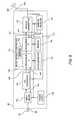
- FIG. 2is a schematic of one embodiment of the data acquisition device and system of the present invention.
- a data acquisition system(similar to that shown in FIG. 3 ) is used to receive, filter, and optionally analyze signals from sensors (not shown) on a subject (not shown).
- the data acquisition system(shown in FIG. 3 ) transmits a signal based, at least in part, on one or more of the signals from the sensors on the subject.
- the data acquisition device and systemtransmits the signal 55 from the subject's home 86 , a hospital 87 , or even a mobile remote location such as a sleeper of a semi-trailer truck 84 to a server 70 for analysis.
- the signalis transmitted over the internet or other communication system 58 .
- the signal 55 that is transmitted over the internet or other communication system 58can be compressed to provide better resolution or greater efficiency.
- the server 70 in this embodimentmay also perform data analysis (not shown).
- the analyzed data 73is then entered into a database 76 .
- the analyzed data 73 in the database 76can then be requested 79 and sent 63 to review stations 82 anywhere in the world via the internet or other communication system 58 for further analysis and review by clinicians, technicians, researchers, physicians and the like.
- the communications systems used for data transmissionneed not be the same at all stages.
- a cellular networkcan be used to transmit data between the subject's home 86 and the remote analysis server 70 .
- the internetcan then be used to transmit data between the remote analysis server 70 and the database 76 .
- a LANcould be used to transmit data between the database 76 and a review station 82 .
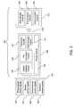
- FIG. 3is a block diagram showing the data flow through the data acquisition system 350 used in certain embodiments of the present invention.
- various sensorsgenerate physiological signals 322 , kinetic signals 324 , environmental signals 326 , and biometric signals 328 .
- the sensor signals 330are input into the data acquisition system 350 , consisting of (a) a data acquisition device 208 containing a sensor interface module 336 , a preprocessor module 338 , a transceiver module 340 , a data storage module 341 , and a power module 334 , and (b) a base station 212 containing a storage module 348 , a second pre-processor module 346 , and a communication module 344 .
- the data acquisition device 208is worn by the subject during the test period.
- the power module 334can be battery-powered.
- the data acquisition device 208sends data via wireless signal 206 to the base station 212 .
- the base station 212uses the communication module 344 to retransmit the signals from the sensors 330 and/or transmit signals based at least in part on at least one of the signals to remote stations (not shown).
- all sensor signals 330could be channeled directly into the data storage module 341 of the data acquisition device 208 and saved for download and analysis at a later time, eliminating the need for wireless transmission of data 206 to the base station 212 .
- all sensor signals 330could be directed into the data storage module 341 and saved for later download while simultaneously being transmitted to a remote station (not shown) via wireless communication 206 with the base station 212 .
- a remote stationnot shown
- transmission between the data acquisition device 208 and the base station 212is shown in FIG. 3 as wireless 206
- the connectioncould also be a wired connection in other embodiments of the data acquisition system.
- FIG. 4is a signal flow diagram showing the flow of biometric data in one embodiment of the present invention.
- a biometric sensing device 200is used to collect and record biometric data and subsequently verify subject identity during the course of a sleep test.
- biometric datais collected using a biometric sensor 101 then processed and stored 102 within the biometric sensing device 200 .
- a simple pass/fail result 106preferably, but not necessarily is output by the biometric sensing device 200 and communicated 108 to the data acquisition device 208 while the biometric identification data itself may remain stored 102 on the biometric sensing device 200 .
- the pass/fail result output 106 by the biometric sensing device 200may be stored in the data acquisition device 208 , wirelessly transmitted to a remote station 206 , 212 or a combination of both.
- the biometric sensing device 200may consist of only a biometric sensor 101 which is capable of capturing biometric data for export to the data acquisition device 208 where it is stored, processed, and subsequently used for subject identification.
- transmission between the data acquisition device 208 and the base station 212is shown in FIG. 4 as wireless 206 , the connection could also be a wired connection in other embodiments of the present invention.
- FIG. 5is a flow chart of one embodiment of the method for using a biometric sensor or sensors to verify a subject's identity during a sleep analysis procedure.
- a biometric characteristic or parameterPrior to beginning sleep analysis testing, a biometric characteristic or parameter is collected and recorded at the office of the subject's physician or collected from some other reliable, preexisting source 62 . Once recorded, this parameter is used by the biometric sensor to verify the subject's identity during the course of the sleep analysis procedure.
- the biometric sensoris then applied to the subject 64 either by the physician, technician or the like while at the physician's office or by the subject himself at a later time but prior to beginning the sleep analysis test. Either before or after (after shown here) application of the biometric sensor to the subject, the biometric sensor is connected to a data acquisition system 66 .
- the sleep testcan be started when the subject attempts to sleep 68 .
- data collectionbegins and the biometric sensor verifies subject identity continuously, randomly, or periodically for the duration of the test 70 . If at any time during the sleep test the biometric sensor is unable to positively verify the identity of the test subject against the previously recorded biometric data for a prespecified successive number of attempts, the subject is alerted and/or the sleep analysis test is stopped 72 , 74 . If subject identity is positively verified, data is recorded and/or transmitted as normal 72 , 76 . Based on the collected and/or transmitted data a sleep analysis is performed and the subject is diagnosed 78 .
- FIG. 6shows various preferred embodiments of a biometric sensing device, more specifically a fingerprint sensor, used in the present invention to verify subject identity during the course of sleep analysis and, optionally, to collect biometric data.
- a pulse oximeteris used in combination with a biometric sensing device in such a way that the pulse oximeter is worn on the same hand as the biometric sensing device. As already noted, this serves to ensure that the individual for whom sleep data is being recorded is in fact the individual from whom pulse oximetry data is collected and for whom sleep analysis was intended.
- a pulse oximeteris used in combination with a biometric sensing device in such a way that biometric verification of subject identity and pulse oximetry are performed on the same digit or finger 540 .
- FIG. 6 aprovides a cross-sectional view of this embodiment showing a fingerprint sensor 542 positioned to read a subject's fingerprint and a pulse oximeter positioned to collect data from the same digit 544 .
- FIG. 6 bprovides a perspective view of this embodiment 540 as it could be used on the hand of an individual subject.
- this embodimentis shown as being used on a subject's index finger 546 , it is not limited to use on this digit and could be used on any other desired digit of the hand. Further, it is envisioned that this embodiment would allow biometric verification and pulse oximetry measurements to occur on the same digit simultaneously or in an alternating fashion.
- a biometric sensing device and pulse oximeterare used in a shared finger-gripping device 550 in such a way that pulse oximetry and biometric verification must occur on two adjacent digits of the same hand. In this embodiment, it is insignificant on which digit biometric verification of identity occurs and on which digit pulse oximetry occurs. Communication with the data acquisition device in this embodiment is performed through a single connection 552 .
- pulse oximetry and biometric verification of identityare performed on separate, optionally non-adjacent digits.
- the pulse oximeter 564is linked to the biometric sensing device 200 by a shared communication connection 560 to the data acquisition device (not shown) in such a way as to require that both devices be used on the same hand.
- the biometric sensing device 200is linked to the pulse oximeter 564 by a shared communication connection 560 to the data acquisition device (not shown) it is envisioned that various other means could be used to physically link the two devices.
- the devicesneed not use a shared communication connection 560 and may communicate with the data acquisition device (not shown) using separate, individual channels.
- the two devicescould be linked through a different type of physical connection such as a short length of braided polymer or other similar material.
- Data collected and/or transmitted using any of the various embodiments shown in FIG. 6could be transmitted to the data acquisition device (not shown) using a shared, single channel or any combination of multiple channels.
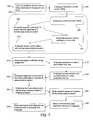
- FIG. 7is a flow diagram showing one embodiment of the method and process of the present invention.
- a trucking company or similar entitydesires sleep testing or sleep screening for one or more employees 400 .
- a single employee truck driveris chosen for sleep screening 400 and subsequently referred to an on-site nurse's office 402 .
- the nurse's officeis represented by box 404 .
- the employeereceives instruction on proper use and application of the sleep analysis system 408 .
- this instructionincludes printed guides outlining proper use of the system for future reference and review by the employee.
- this instructioncould include multimedia references such as instructional digital versatile discs, or the like.
- employee biometric datais collected and recorded 410 for use in verification of identity during remote sleep testing. Collection of biometric data is preferably performed using the biometric sensing device (shown in FIG. 4 ). Proper function of the biometric identification step (not shown) is also preferably verified at the time of biometric data collection 410 .
- the employeethen leaves the nurse's office carrying the sleep analysis system 412 , in this case, comprised of a multi-channel data acquisition device and the proper sensors. In the present embodiment the employee would then return to work and begin a multi-day driving assignment 414 .
- the employeestops to sleep while still en route to his or her final destination and prepares to sleep in the sleeping area of the cab of the semi-trailer truck 416 which he or she has been operating.
- the employeePrior to sleep, the employee applies the sensors to his or her actual person and connects the sensors to the data acquisition device 418 according to the provided instructions 408 .
- Sleep datais then recorded by the sleep analysis system for a minimum of two hours of sleep 420 .
- the employee identityis also verified by the biometric sensing device (shown in FIG. 4 ).
- the employeeUpon awakening from sleep, the employee removes the sleep sensors and places the sensors and data acquisition device in a prepaid envelope 422 for mailing to an off-site sleep analysis station 424 .
- This envelopeis then mailed from a suitable location at the convenience of the employee.
- the datais removed from the data acquisition device and analyzed by a technician, clinician, physician, or the like 426 and a diagnosis is made and sent to both employer and employee 428 .
- FIG. 8is a block diagram showing one envisioned method and process of use for one specific embodiment of the present invention.
- an airline or similar entitydesires sleep testing or sleep screening for one or more employees 440 .
- a single employee pilotis chosen for sleep screening 440 and subsequently scheduled to attend an in-office training meeting on proper use of sleep analysis equipment 442 .
- the training meetingis represented by box 444 .
- the employeereceives instruction on proper use and application of the sleep analysis system 448 .
- this instructionincludes printed guides outlining proper use of the system for future reference and review by the employee.
- this instructioncould include multimedia references such as instructional digital versatile discs, or the like.
- employee biometric datais collected and recorded 450 for use in verification of identity during remote sleep testing. Collection of biometric data is preferably performed using the biometric sensing device (shown in FIG. 4 ). Proper function of the biometric identification step (not shown) is also preferably verified at the time of biometric data collection 450 .
- the employeethen leaves the training meeting carrying the sleep analysis system 452 , in this case, comprised of a multi-channel data acquisition device capable of wireless communication, a wireless communication receiver, an external programming and analysis device (e.g. a notebook computer) and the proper sleep sensors. In the present embodiment, the employee would then return to work and begin a multi-day travel/flight assignment 454 .
- the employeestops to sleep during the travel/flight assignment at a hotel with internet access 456 or access to another similar communication system.
- the employeeapplies the sensors to his or her actual person and connects the sensors to the data acquisition device 458 according to the provided instructions 448 .
- the employeeensures that the wireless communication between the data acquisition device and the wireless receiver station is function properly 460 and that data transmission and communication between the external programming device and remote sleep analysis station is functioning properly 462 .
- telephone or other live communication supportis available for the steps of connecting the sleep analysis system 458 , 460 , 462 . Sleep data is then recorded and transmitted to a remote sleep analysis station by the sleep analysis system for a minimum of two hours of sleep 464 .
- employee identityis also verified by the biometric sensing device (shown in FIG. 4 ).
- the employeeUpon awakening from sleep, the employee removes the sleep sensors and returns the sleep analysis system using a prepaid mailing package or by drop-off at any company office.
- the data transmitted in 464is analyzed either in real-time, during transmission, or at some time shortly afterward by a technician, clinician, physician, or the like and a diagnosis is made and sent to both employer and employee 468 .
- the signal processing module 85comprises input means 115 , analog-to-digital (A/D) means 118 , a module microcontroller 121 with a nonvolatile memory, advantageously, an EEPROM 124 , a module transmitter 127 , a connection to removable memory 130 , a module receiver 133 and a module power supply 136 .
- a module power supply 136provides electrical power to the signal processing module 85 .
- the signal processing module 85will preferably contain an accelerometer 131 connected to a microprocessor 139 for position detection, motion detection, and motion artifact correction.
- the input means 115is adjustable either under control of the module microcontroller 121 or by means of individually populatable components based upon the specific external input 88 (i.e. a signal from any sensor) characteristics and range enabling the input means 115 to accept that specific external input 88 .
- the external input 88is inputted to the A/D means 118 .
- the A/D means 118converts the input to a digital signal 142 and conditions it.
- the A/D means 118utilizes at least one programmable A/D converter. This programmable A/D converter may be an AD7714 as manufactured by Analog Devices or similar.
- the input means 115may also include at least one low noise differential preamp. This preamp may be an INA126 as manufactured by Burr-Brown or similar.
- the module microcontroller 121can be programmed to control the input means 115 and the A/D means 118 to provide specific number of external inputs 88 , sampling rate, filtering and gain.
- These parametersare initially configured by programming the module microcontroller 121 to control the input means 115 and the A/D means 118 via input communications line 145 and A/D communications line 148 based upon the input characteristics and the particular application. If different sensors are used, the A/D converter is reconfigured by reprogramming the module microcontroller 121 .
- the module microcontroller 121controls the operation of the signal processing module 85 .
- the module microcontroller 121includes a serial EEPROM 124 but any nonvolatile memory (or volatile memory if the signal processing module remains powered) can be used.
- the EEPROM 124can also be a separate component external to the module microcontroller 121 .
- the module microcontrollermay advantageously contain two microprocessors in series as shown in FIG. 9 .
- the module microcontroller 121is programmed by the external programming means (shown in FIG. 1 ) through the connector 172 or through radio frequency signal from the base station (shown in FIG. 3 ). The same module microcontroller 121 , therefore, can be utilized for all applications and inputs by programming it for those applications and inputs.
- the module microcontroller 121is modified by merely reprogramming.
- the digital signal 142is inputted to the module microcontroller 121 .
- the module microcontroller 121formats the digital signal 142 into a digital data stream 151 encoded with the data from the digital signal 142 .
- the digital data stream 151is composed of data bytes corresponding to the encoded data and additional data bytes to provide error correction and housekeeping functions.
- the digital data stream 151is used to modulate the carrier frequency generated by the transmitter 127 .
- the module transmitter 127is under module microcontroller 121 control.
- the module transmitter 127employs frequency synthesis to generate the carrier frequency. In the preferred embodiment, this frequency synthesis is accomplished by a voltage controlled crystal reference oscillator and a voltage controlled oscillator in a phase lock loop circuit.
- the digital data stream 151is used to frequency modulate the carrier frequency resulting in the wireless data transmission signal 206 which is then transmitted through the module antenna 100 .
- the generation of the carrier frequencyis controlled by the module microcontroller 121 through programming in the EEPROM 124 , making the module transmitter 127 frequency agile over a broad frequency spectrum. In the United States and Canada a preferred operating band for the carrier frequency is 902 to 928 MHz.
- the EEPROM 124can be programmed such that the module microcontroller 121 can instruct the module transmitter 127 to generate a carrier frequency in increments between 902 to 928 MHz. as small as about 5 to 10 kHz.
- the carrier frequencymay be in the 902-928 MHz, Wireless Medical Telemetry Bands (WMTS), 608-614 MHz, 1395-1400 MHz, or 1429-1432 MHz or other authorized band. This allows the system to be usable in non-North American applications and provides additional flexibility.
- WMTSWireless Medical Telemetry Bands
- the voltage controlled crystal oscillator (not shown) in the module transmitter 127not only provides the reference frequency for the module transmitter 127 but, advantageously also provides the clock function 154 for the module microcontroller 121 and the A/D means 118 assuring that all components of the signal processing module 85 are synchronized.
- An alternate designcan use a plurality of reference frequency sources where this arrangement can provide certain advantages such as size or power consumption in the implementation.
- the module receiver 133 in the signal processing module 85receives RF signals from the base station (shown in FIG. 3 ). The signals from the base station can be used to operate and control the signal processing module 85 by programming and reprogramming the module microprocessor 121 and EEPROM 124 therein.
- the signal processing module 85 of the data acquisition devicemay include an output means (not shown).
- the processor 139may have a connection to an output means through which processed digital information could be passed to an external device, such as a fingerprint sensing device, in order to modulate the function of the external device.
- digital informationmay pass first through the A/D converter 118 and be converted to analog format prior to being sent via the output means to an external analog device.
Landscapes
- Health & Medical Sciences (AREA)
- Life Sciences & Earth Sciences (AREA)
- Engineering & Computer Science (AREA)
- Physics & Mathematics (AREA)
- Biomedical Technology (AREA)
- General Health & Medical Sciences (AREA)
- Medical Informatics (AREA)
- Public Health (AREA)
- Pathology (AREA)
- Heart & Thoracic Surgery (AREA)
- Molecular Biology (AREA)
- Surgery (AREA)
- Animal Behavior & Ethology (AREA)
- Veterinary Medicine (AREA)
- Biophysics (AREA)
- Computer Networks & Wireless Communication (AREA)
- Physiology (AREA)
- Cardiology (AREA)
- Spectroscopy & Molecular Physics (AREA)
- Optics & Photonics (AREA)
- Theoretical Computer Science (AREA)
- General Business, Economics & Management (AREA)
- Human Computer Interaction (AREA)
- General Physics & Mathematics (AREA)
- Multimedia (AREA)
- Primary Health Care (AREA)
- Epidemiology (AREA)
- Business, Economics & Management (AREA)
- Anesthesiology (AREA)
- Pulmonology (AREA)
- Psychology (AREA)
- Psychiatry (AREA)
- Ophthalmology & Optometry (AREA)
- Measurement Of The Respiration, Hearing Ability, Form, And Blood Characteristics Of Living Organisms (AREA)
Abstract
Description
Claims (7)
Priority Applications (5)
| Application Number | Priority Date | Filing Date | Title |
|---|---|---|---|
| US12/228,461US8679012B1 (en) | 2008-08-13 | 2008-08-13 | Medical device and method with improved biometric verification |
| US14/173,897US9943252B1 (en) | 2008-08-13 | 2014-02-06 | Medical device and method with improved biometric verification |
| US15/910,068US10413222B1 (en) | 2008-08-13 | 2018-03-02 | Medical device and method with improved biometric verification |
| US16/531,502US11419525B1 (en) | 2008-08-13 | 2019-08-05 | Medical device and method with improved biometric verification |
| US17/862,761US12016679B1 (en) | 2008-08-13 | 2022-07-12 | Medical device and method with improved biometric verification |
Applications Claiming Priority (1)
| Application Number | Priority Date | Filing Date | Title |
|---|---|---|---|
| US12/228,461US8679012B1 (en) | 2008-08-13 | 2008-08-13 | Medical device and method with improved biometric verification |
Related Child Applications (1)
| Application Number | Title | Priority Date | Filing Date |
|---|---|---|---|
| US14/173,897ContinuationUS9943252B1 (en) | 2008-08-13 | 2014-02-06 | Medical device and method with improved biometric verification |
Publications (1)
| Publication Number | Publication Date |
|---|---|
| US8679012B1true US8679012B1 (en) | 2014-03-25 |
Family
ID=50288776
Family Applications (5)
| Application Number | Title | Priority Date | Filing Date |
|---|---|---|---|
| US12/228,461Active2031-08-06US8679012B1 (en) | 2008-08-13 | 2008-08-13 | Medical device and method with improved biometric verification |
| US14/173,897Active2030-10-05US9943252B1 (en) | 2008-08-13 | 2014-02-06 | Medical device and method with improved biometric verification |
| US15/910,068ActiveUS10413222B1 (en) | 2008-08-13 | 2018-03-02 | Medical device and method with improved biometric verification |
| US16/531,502Active2029-03-18US11419525B1 (en) | 2008-08-13 | 2019-08-05 | Medical device and method with improved biometric verification |
| US17/862,761ActiveUS12016679B1 (en) | 2008-08-13 | 2022-07-12 | Medical device and method with improved biometric verification |
Family Applications After (4)
| Application Number | Title | Priority Date | Filing Date |
|---|---|---|---|
| US14/173,897Active2030-10-05US9943252B1 (en) | 2008-08-13 | 2014-02-06 | Medical device and method with improved biometric verification |
| US15/910,068ActiveUS10413222B1 (en) | 2008-08-13 | 2018-03-02 | Medical device and method with improved biometric verification |
| US16/531,502Active2029-03-18US11419525B1 (en) | 2008-08-13 | 2019-08-05 | Medical device and method with improved biometric verification |
| US17/862,761ActiveUS12016679B1 (en) | 2008-08-13 | 2022-07-12 | Medical device and method with improved biometric verification |
Country Status (1)
| Country | Link |
|---|---|
| US (5) | US8679012B1 (en) |
Cited By (90)
| Publication number | Priority date | Publication date | Assignee | Title |
|---|---|---|---|---|
| US20120068820A1 (en)* | 2010-09-20 | 2012-03-22 | Pulsar Information, Inc. | Systems and Methods for Collecting Biometrically Verified Actigraphy Data |
| US20120179066A1 (en)* | 2006-10-18 | 2012-07-12 | Yuan Ze University | Sleeping quality monitor system and a method for monitoring a physiological signal |
| US20150048956A1 (en)* | 2012-04-12 | 2015-02-19 | Welcoop Pharma | Medical device for the measurement and processing of a health parameter of a patient |
| US20150051453A1 (en)* | 2011-09-06 | 2015-02-19 | Resmed Sensor Technologies Limited | Multi-modal sleep system |
| US20150157239A1 (en)* | 2013-12-06 | 2015-06-11 | Clarkson University | Cardiovascular and Pulmonary Radar System |
| US9202008B1 (en)* | 2007-06-08 | 2015-12-01 | Cleveland Medical Devices Inc. | Method and device for sleep analysis |
| US20160175614A1 (en)* | 2014-12-19 | 2016-06-23 | Kabushiki Kaisha Toshiba | Medical image processing apparatus, treatment system, medical image processing method, and medical image processing program |
| US20160188803A1 (en)* | 2014-12-29 | 2016-06-30 | Lg Cns Co., Ltd. | Apparatus and method for checking care providing site visit of user |
| US20160361020A1 (en)* | 2014-02-28 | 2016-12-15 | Valencell, Inc. | Method and Apparatus for Generating Assessments Using Physical Activity and Biometric Parameters |
| ES2608815A1 (en)* | 2016-07-25 | 2017-04-17 | Universidad De Murcia | Ambulatory device for monitoring circadian rhythms, sleep, environments and movement patterns. (Machine-translation by Google Translate, not legally binding) |
| WO2017067993A1 (en)* | 2015-10-20 | 2017-04-27 | Bragi GmbH | Multiple sensor array for data sensing and processing |
| CN106709459A (en)* | 2016-12-27 | 2017-05-24 | 努比亚技术有限公司 | Fingerprint identification method and mobile terminal |
| US20170215799A1 (en)* | 2010-12-22 | 2017-08-03 | Sleepsafe Drivers, Inc. | Advanced system and method for oxygen saturation monitoring |
| WO2017193915A1 (en)* | 2016-05-09 | 2017-11-16 | Belun Technology Company Limited | Wearable device for healthcare and method thereof |
| JP2017213275A (en)* | 2016-06-01 | 2017-12-07 | オムロンヘルスケア株式会社 | Biological information measurement device, method for determining correctness of biological information, and program for determining correctness of biological information |
| US9848458B2 (en)* | 2014-12-01 | 2017-12-19 | Oceus Networks, Inc. | Wireless parameter-sensing node and network thereof |
| US9943252B1 (en)* | 2008-08-13 | 2018-04-17 | Cleveland Medical Devices Inc. | Medical device and method with improved biometric verification |
| US20180140228A1 (en)* | 2016-11-23 | 2018-05-24 | Lifeq Global Limited | System and Method for Biometric Identification Using Sleep Physiology |
| US10055963B1 (en)* | 2017-02-07 | 2018-08-21 | Honeywell International Inc. | On-duty/off-duty work alternation planning based on sensed physiological and activity parameters |
| US10058282B2 (en) | 2016-11-04 | 2018-08-28 | Bragi GmbH | Manual operation assistance with earpiece with 3D sound cues |
| CN108814606A (en)* | 2018-05-15 | 2018-11-16 | 京东方科技集团股份有限公司 | Device, method and system for monitoring respiratory state |
| US10135822B2 (en)* | 2017-03-21 | 2018-11-20 | YouaretheID, LLC | Biometric authentication of individuals utilizing characteristics of bone and blood vessel structures |
| WO2018220606A1 (en) | 2017-06-02 | 2018-12-06 | Nox Medical Ehf | Coherence-based method, apparatus, and system for identifying corresponding signals of a physiological study |
| US10169561B2 (en) | 2016-04-28 | 2019-01-01 | Bragi GmbH | Biometric interface system and method |
| US10205814B2 (en) | 2016-11-03 | 2019-02-12 | Bragi GmbH | Wireless earpiece with walkie-talkie functionality |
| CN109414219A (en)* | 2016-03-24 | 2019-03-01 | 伊里瑟奇科技公司 | Method and system for collecting spirometry data |
| US10229288B2 (en) | 2016-05-17 | 2019-03-12 | International Business Machines Corporation | Enhanced data security platform |
| US10297911B2 (en) | 2015-08-29 | 2019-05-21 | Bragi GmbH | Antenna for use in a wearable device |
| US10313781B2 (en) | 2016-04-08 | 2019-06-04 | Bragi GmbH | Audio accelerometric feedback through bilateral ear worn device system and method |
| JP2019101642A (en)* | 2017-11-30 | 2019-06-24 | ユニファ株式会社 | Child-care management system, server device, child-care management program, and child-care management method |
| US20190206416A1 (en)* | 2017-12-28 | 2019-07-04 | Sleep Number Corporation | Home automation having user privacy protections |
| US10344960B2 (en) | 2017-09-19 | 2019-07-09 | Bragi GmbH | Wireless earpiece controlled medical headlight |
| US10382854B2 (en) | 2015-08-29 | 2019-08-13 | Bragi GmbH | Near field gesture control system and method |
| US10397688B2 (en) | 2015-08-29 | 2019-08-27 | Bragi GmbH | Power control for battery powered personal area network device system and method |
| US10397690B2 (en) | 2016-11-04 | 2019-08-27 | Bragi GmbH | Earpiece with modified ambient environment over-ride function |
| US10405081B2 (en) | 2017-02-08 | 2019-09-03 | Bragi GmbH | Intelligent wireless headset system |
| EP3534371A1 (en)* | 2018-02-28 | 2019-09-04 | Karl Storz Imaging, Inc. | System and method for identifying and authenticating a user of a medical device, and controlling access to patient data generated by the medical device |
| US10412493B2 (en) | 2016-02-09 | 2019-09-10 | Bragi GmbH | Ambient volume modification through environmental microphone feedback loop system and method |
| US10412478B2 (en) | 2015-08-29 | 2019-09-10 | Bragi GmbH | Reproduction of ambient environmental sound for acoustic transparency of ear canal device system and method |
| US10426399B1 (en)* | 2007-06-08 | 2019-10-01 | Cleveland Medial Devices Inc. | Method and device for in-home sleep and signal analysis |
| US10433788B2 (en) | 2016-03-23 | 2019-10-08 | Bragi GmbH | Earpiece life monitor with capability of automatic notification system and method |
| US10448139B2 (en) | 2016-07-06 | 2019-10-15 | Bragi GmbH | Selective sound field environment processing system and method |
| US10470709B2 (en) | 2016-07-06 | 2019-11-12 | Bragi GmbH | Detection of metabolic disorders using wireless earpieces |
| US10506327B2 (en) | 2016-12-27 | 2019-12-10 | Bragi GmbH | Ambient environmental sound field manipulation based on user defined voice and audio recognition pattern analysis system and method |
| US10506328B2 (en) | 2016-03-14 | 2019-12-10 | Bragi GmbH | Explosive sound pressure level active noise cancellation |
| US10548497B2 (en) | 2009-05-15 | 2020-02-04 | Nox Medical | Systems and methods using flexible capacitive electrodes for measuring biosignals |
| US10575086B2 (en) | 2017-03-22 | 2020-02-25 | Bragi GmbH | System and method for sharing wireless earpieces |
| US10582290B2 (en) | 2017-02-21 | 2020-03-03 | Bragi GmbH | Earpiece with tap functionality |
| US10582289B2 (en) | 2015-10-20 | 2020-03-03 | Bragi GmbH | Enhanced biometric control systems for detection of emergency events system and method |
| US10588550B2 (en) | 2013-11-06 | 2020-03-17 | Nox Medical | Method, apparatus, and system for measuring respiratory effort |
| US10620698B2 (en) | 2015-12-21 | 2020-04-14 | Bragi GmbH | Voice dictation systems using earpiece microphone system and method |
| US10672239B2 (en) | 2015-08-29 | 2020-06-02 | Bragi GmbH | Responsive visual communication system and method |
| US10681450B2 (en) | 2016-11-04 | 2020-06-09 | Bragi GmbH | Earpiece with source selection within ambient environment |
| US10681449B2 (en) | 2016-11-04 | 2020-06-09 | Bragi GmbH | Earpiece with added ambient environment |
| US10708699B2 (en) | 2017-05-03 | 2020-07-07 | Bragi GmbH | Hearing aid with added functionality |
| US10771881B2 (en) | 2017-02-27 | 2020-09-08 | Bragi GmbH | Earpiece with audio 3D menu |
| US10869619B2 (en) | 2016-08-19 | 2020-12-22 | Nox Medical | Method, apparatus, and system for measuring respiratory effort of a subject |
| US10893353B2 (en) | 2016-03-11 | 2021-01-12 | Bragi GmbH | Earpiece with GPS receiver |
| US10896665B2 (en) | 2016-11-03 | 2021-01-19 | Bragi GmbH | Selective audio isolation from body generated sound system and method |
| US10904653B2 (en) | 2015-12-21 | 2021-01-26 | Bragi GmbH | Microphone natural speech capture voice dictation system and method |
| US10923216B1 (en)* | 2020-06-12 | 2021-02-16 | Tensorx, Inc. | Health status system, platform, and method |
| US11013445B2 (en) | 2017-06-08 | 2021-05-25 | Bragi GmbH | Wireless earpiece with transcranial stimulation |
| US11064408B2 (en) | 2015-10-20 | 2021-07-13 | Bragi GmbH | Diversity bluetooth system and method |
| US11116415B2 (en) | 2017-06-07 | 2021-09-14 | Bragi GmbH | Use of body-worn radar for biometric measurements, contextual awareness and identification |
| US11132430B2 (en)* | 2017-12-04 | 2021-09-28 | Advanced New Technologies Co., Ltd. | Login method and apparatus and electronic device |
| US20220067133A1 (en)* | 2007-09-24 | 2022-03-03 | Apple Inc. | Embedded authentication systems in an electronic device |
| US11272367B2 (en) | 2017-09-20 | 2022-03-08 | Bragi GmbH | Wireless earpieces for hub communications |
| CN114519869A (en)* | 2020-11-20 | 2022-05-20 | 映智科技股份有限公司 | Biological characteristic sensor device |
| US11369315B2 (en)* | 2017-06-26 | 2022-06-28 | Samuel Kerem | Multifunctional personal health monitor with an activity tracker embedded into a pet leash |
| US11380430B2 (en) | 2017-03-22 | 2022-07-05 | Bragi GmbH | System and method for populating electronic medical records with wireless earpieces |
| US11432724B1 (en) | 2006-06-16 | 2022-09-06 | Cleveland Medical Devices Inc. | Wireless data acquisition system with novel features |
| US11544104B2 (en) | 2017-03-22 | 2023-01-03 | Bragi GmbH | Load sharing between wireless earpieces |
| US11602282B2 (en) | 2017-09-08 | 2023-03-14 | Nox Medical Ehf | System and method for non-invasively determining an internal component of respiratory effort |
| US11619991B2 (en) | 2018-09-28 | 2023-04-04 | Apple Inc. | Device control using gaze information |
| US11676373B2 (en) | 2008-01-03 | 2023-06-13 | Apple Inc. | Personal computing device control using face detection and recognition |
| US11672934B2 (en) | 2020-05-12 | 2023-06-13 | Covidien Lp | Remote ventilator adjustment |
| US11694771B2 (en) | 2017-03-22 | 2023-07-04 | Bragi GmbH | System and method for populating electronic health records with wireless earpieces |
| US11755712B2 (en) | 2011-09-29 | 2023-09-12 | Apple Inc. | Authentication with secondary approver |
| US11765163B2 (en) | 2017-09-09 | 2023-09-19 | Apple Inc. | Implementation of biometric authentication |
| US11768575B2 (en) | 2013-09-09 | 2023-09-26 | Apple Inc. | Device, method, and graphical user interface for manipulating user interfaces based on unlock inputs |
| US11809784B2 (en) | 2018-09-28 | 2023-11-07 | Apple Inc. | Audio assisted enrollment |
| US11836725B2 (en) | 2014-05-29 | 2023-12-05 | Apple Inc. | User interface for payments |
| US11928200B2 (en) | 2018-06-03 | 2024-03-12 | Apple Inc. | Implementation of biometric authentication |
| US12079458B2 (en) | 2016-09-23 | 2024-09-03 | Apple Inc. | Image data for enhanced user interactions |
| US12099586B2 (en) | 2021-01-25 | 2024-09-24 | Apple Inc. | Implementation of biometric authentication |
| JP2024141010A (en)* | 2023-03-28 | 2024-10-10 | 株式会社Taos研究所 | Live body determination method, live body determination system, and live body determination program |
| US12210603B2 (en) | 2021-03-04 | 2025-01-28 | Apple Inc. | User interface for enrolling a biometric feature |
| US12216754B2 (en) | 2021-05-10 | 2025-02-04 | Apple Inc. | User interfaces for authenticating to perform secure operations |
| US12262111B2 (en) | 2011-06-05 | 2025-03-25 | Apple Inc. | Device, method, and graphical user interface for accessing an application in a locked device |
| US12437047B1 (en)* | 2022-04-26 | 2025-10-07 | Advanced Neuromodulation Systems, Inc. | Digital healthcare architecture with biometric authentication systems and methods |
Families Citing this family (31)
| Publication number | Priority date | Publication date | Assignee | Title |
|---|---|---|---|---|
| US11801423B2 (en) | 2019-05-10 | 2023-10-31 | Rehab2Fit Technologies, Inc. | Method and system for using artificial intelligence to interact with a user of an exercise device during an exercise session |
| US12402804B2 (en) | 2019-09-17 | 2025-09-02 | Rom Technologies, Inc. | Wearable device for coupling to a user, and measuring and monitoring user activity |
| US12427376B2 (en) | 2019-10-03 | 2025-09-30 | Rom Technologies, Inc. | Systems and methods for an artificial intelligence engine to optimize a peak performance |
| US20210134412A1 (en) | 2019-10-03 | 2021-05-06 | Rom Technologies, Inc. | System and method for processing medical claims using biometric signatures |
| US12154672B2 (en) | 2019-10-03 | 2024-11-26 | Rom Technologies, Inc. | Method and system for implementing dynamic treatment environments based on patient information |
| US12230381B2 (en) | 2019-10-03 | 2025-02-18 | Rom Technologies, Inc. | System and method for an enhanced healthcare professional user interface displaying measurement information for a plurality of users |
| US11955222B2 (en) | 2019-10-03 | 2024-04-09 | Rom Technologies, Inc. | System and method for determining, based on advanced metrics of actual performance of an electromechanical machine, medical procedure eligibility in order to ascertain survivability rates and measures of quality-of-life criteria |
| US12176089B2 (en) | 2019-10-03 | 2024-12-24 | Rom Technologies, Inc. | System and method for using AI ML and telemedicine for cardio-oncologic rehabilitation via an electromechanical machine |
| US12224052B2 (en) | 2019-10-03 | 2025-02-11 | Rom Technologies, Inc. | System and method for using AI, machine learning and telemedicine for long-term care via an electromechanical machine |
| US12150792B2 (en) | 2019-10-03 | 2024-11-26 | Rom Technologies, Inc. | Augmented reality placement of goniometer or other sensors |
| US11282599B2 (en) | 2019-10-03 | 2022-03-22 | Rom Technologies, Inc. | System and method for use of telemedicine-enabled rehabilitative hardware and for encouragement of rehabilitative compliance through patient-based virtual shared sessions |
| US12220201B2 (en) | 2019-10-03 | 2025-02-11 | Rom Technologies, Inc. | Remote examination through augmented reality |
| US12100499B2 (en) | 2020-08-06 | 2024-09-24 | Rom Technologies, Inc. | Method and system for using artificial intelligence and machine learning to create optimal treatment plans based on monetary value amount generated and/or patient outcome |
| US12420145B2 (en) | 2019-10-03 | 2025-09-23 | Rom Technologies, Inc. | Systems and methods of using artificial intelligence and machine learning for generating alignment plans to align a user with an imaging sensor during a treatment session |
| US11270795B2 (en) | 2019-10-03 | 2022-03-08 | Rom Technologies, Inc. | Method and system for enabling physician-smart virtual conference rooms for use in a telehealth context |
| US11282604B2 (en) | 2019-10-03 | 2022-03-22 | Rom Technologies, Inc. | Method and system for use of telemedicine-enabled rehabilitative equipment for prediction of secondary disease |
| US11317975B2 (en) | 2019-10-03 | 2022-05-03 | Rom Technologies, Inc. | Method and system for treating patients via telemedicine using sensor data from rehabilitation or exercise equipment |
| US11515021B2 (en) | 2019-10-03 | 2022-11-29 | Rom Technologies, Inc. | Method and system to analytically optimize telehealth practice-based billing processes and revenue while enabling regulatory compliance |
| US11282608B2 (en) | 2019-10-03 | 2022-03-22 | Rom Technologies, Inc. | Method and system for using artificial intelligence and machine learning to provide recommendations to a healthcare provider in or near real-time during a telemedicine session |
| US12246222B2 (en) | 2019-10-03 | 2025-03-11 | Rom Technologies, Inc. | Method and system for using artificial intelligence to assign patients to cohorts and dynamically controlling a treatment apparatus based on the assignment during an adaptive telemedical session |
| US11139060B2 (en) | 2019-10-03 | 2021-10-05 | Rom Technologies, Inc. | Method and system for creating an immersive enhanced reality-driven exercise experience for a user |
| US11265234B2 (en) | 2019-10-03 | 2022-03-01 | Rom Technologies, Inc. | System and method for transmitting data and ordering asynchronous data |
| US12327623B2 (en) | 2019-10-03 | 2025-06-10 | Rom Technologies, Inc. | System and method for processing medical claims |
| US12191018B2 (en) | 2019-10-03 | 2025-01-07 | Rom Technologies, Inc. | System and method for using artificial intelligence in telemedicine-enabled hardware to optimize rehabilitative routines capable of enabling remote rehabilitative compliance |
| US11087865B2 (en) | 2019-10-03 | 2021-08-10 | Rom Technologies, Inc. | System and method for use of treatment device to reduce pain medication dependency |
| US11826613B2 (en) | 2019-10-21 | 2023-11-28 | Rom Technologies, Inc. | Persuasive motivation for orthopedic treatment |
| US12424319B2 (en) | 2019-11-06 | 2025-09-23 | Rom Technologies, Inc. | System for remote treatment utilizing privacy controls |
| US11107591B1 (en) | 2020-04-23 | 2021-08-31 | Rom Technologies, Inc. | Method and system for describing and recommending optimal treatment plans in adaptive telemedical or other contexts |
| US11910851B2 (en) | 2020-08-11 | 2024-02-27 | Qatar Foundation For Education, Science And Community Development | Smart mask with printed electronics |
| US12367960B2 (en) | 2020-09-15 | 2025-07-22 | Rom Technologies, Inc. | System and method for using AI ML and telemedicine to perform bariatric rehabilitation via an electromechanical machine |
| US20250191718A1 (en)* | 2022-03-03 | 2025-06-12 | The Regents Of The University Of California | Multi-modal crypto/bio-human-machine interface |
Citations (14)
| Publication number | Priority date | Publication date | Assignee | Title |
|---|---|---|---|---|
| US5719950A (en)* | 1994-03-24 | 1998-02-17 | Minnesota Mining And Manufacturing Company | Biometric, personal authentication system |
| US6327376B1 (en) | 1997-12-04 | 2001-12-04 | U.S. Philips Corporation | Electronic apparatus comprising fingerprint sensing devices |
| US6425861B1 (en)* | 1998-12-04 | 2002-07-30 | Respironics, Inc. | System and method for monitoring and controlling a plurality of polysomnographic devices |
| US6643531B1 (en)* | 2002-08-22 | 2003-11-04 | Bci, Inc. | Combination fingerprint and oximetry device |
| US6762684B1 (en)* | 1999-04-19 | 2004-07-13 | Accutrak Systems, Inc. | Monitoring system |
| US20040244807A1 (en)* | 2003-06-04 | 2004-12-09 | Jianguo Sun | Sleep-lab systems and methods |
| US20050030724A1 (en) | 2003-01-22 | 2005-02-10 | Tapani Ryhanen | Sensing arrangement |
| US20050115561A1 (en)* | 2003-08-18 | 2005-06-02 | Stahmann Jeffrey E. | Patient monitoring, diagnosis, and/or therapy systems and methods |
| US6993378B2 (en) | 2001-06-25 | 2006-01-31 | Science Applications International Corporation | Identification by analysis of physiometric variation |
| US20060074280A1 (en) | 2004-10-06 | 2006-04-06 | Martis Dinesh J | Patient identification system |
| US7048183B2 (en) | 2003-06-19 | 2006-05-23 | Scriptpro Llc | RFID rag and method of user verification |
| US20060174120A1 (en)* | 2005-02-02 | 2006-08-03 | Seamless Peer 2 Peer, Inc. | System and method for providing peer-to-peer communication |
| US20090005652A1 (en)* | 2007-05-07 | 2009-01-01 | Ron Kurtz | Method and system for permitting access to equipment, devices, systems, services or the like based on sleep quality analysis |
| US7510531B2 (en)* | 2003-09-18 | 2009-03-31 | Cardiac Pacemakers, Inc. | System and method for discrimination of central and obstructive disordered breathing events |
Family Cites Families (22)
| Publication number | Priority date | Publication date | Assignee | Title |
|---|---|---|---|---|
| AUPP902299A0 (en)* | 1999-03-04 | 1999-03-25 | Hales, Jeff | Wireless sleep monitoring |
| EP2324760B1 (en)* | 2000-04-17 | 2019-07-24 | Adidas AG | System for ambulatory monitoring of physiological signs |
| US6858006B2 (en)* | 2000-09-08 | 2005-02-22 | Wireless Medical, Inc. | Cardiopulmonary monitoring |
| WO2002065901A2 (en)* | 2000-12-29 | 2002-08-29 | Ares Medical, Inc. | Sleep apnea risk evaluation |
| WO2002089667A1 (en)* | 2001-05-03 | 2002-11-14 | Telzuit Technologies, Inc. | Wireless medical monitoring apparatus and system |
| US20020188216A1 (en)* | 2001-05-03 | 2002-12-12 | Kayyali Hani Akram | Head mounted medical device |
| US8282475B2 (en)* | 2001-06-15 | 2012-10-09 | Igt | Virtual leash for personal gaming device |
| US7207948B2 (en)* | 2004-06-24 | 2007-04-24 | Vivometrics, Inc. | Systems and methods for monitoring cough |
| US7727161B2 (en)* | 2003-04-10 | 2010-06-01 | Vivometrics, Inc. | Systems and methods for monitoring cough |
| KR101084554B1 (en)* | 2003-09-12 | 2011-11-17 | 보디미디어 인코퍼레이티드 | Method and apparatus for measuring heart related parameters |
| CA2967756C (en)* | 2004-04-01 | 2018-08-28 | Google Inc. | Biosensors, communicators, and controllers monitoring eye movement and methods for using them |
| US9492084B2 (en)* | 2004-06-18 | 2016-11-15 | Adidas Ag | Systems and methods for monitoring subjects in potential physiological distress |
| US7279806B2 (en)* | 2004-07-27 | 2007-10-09 | Elaine E. Futrell | Ignition system with driver identification |
| US7609145B2 (en)* | 2004-10-06 | 2009-10-27 | Martis Ip Holdings, Llc | Test authorization system |
| US7578793B2 (en)* | 2004-11-22 | 2009-08-25 | Widemed Ltd. | Sleep staging based on cardio-respiratory signals |
| US8033996B2 (en)* | 2005-07-26 | 2011-10-11 | Adidas Ag | Computer interfaces including physiologically guided avatars |
| US9202008B1 (en)* | 2007-06-08 | 2015-12-01 | Cleveland Medical Devices Inc. | Method and device for sleep analysis |
| WO2009036327A1 (en)* | 2007-09-14 | 2009-03-19 | Corventis, Inc. | Adherent device for respiratory monitoring and sleep disordered breathing |
| WO2009134246A1 (en)* | 2008-04-29 | 2009-11-05 | Lotus Magnus, Llc. | Systems, devices, and methods for monitoring a subject |
| US8679012B1 (en)* | 2008-08-13 | 2014-03-25 | Cleveland Medical Devices Inc. | Medical device and method with improved biometric verification |
| US9492105B1 (en)* | 2009-02-13 | 2016-11-15 | Cleveland Medical Devices Inc. | Device for sleep diagnosis |
| US9659159B2 (en)* | 2014-08-14 | 2017-05-23 | Sleep Data Services, Llc | Sleep data chain of custody |
- 2008
- 2008-08-13USUS12/228,461patent/US8679012B1/enactiveActive
- 2014
- 2014-02-06USUS14/173,897patent/US9943252B1/enactiveActive
- 2018
- 2018-03-02USUS15/910,068patent/US10413222B1/enactiveActive
- 2019
- 2019-08-05USUS16/531,502patent/US11419525B1/enactiveActive
- 2022
- 2022-07-12USUS17/862,761patent/US12016679B1/enactiveActive
Patent Citations (14)
| Publication number | Priority date | Publication date | Assignee | Title |
|---|---|---|---|---|
| US5719950A (en)* | 1994-03-24 | 1998-02-17 | Minnesota Mining And Manufacturing Company | Biometric, personal authentication system |
| US6327376B1 (en) | 1997-12-04 | 2001-12-04 | U.S. Philips Corporation | Electronic apparatus comprising fingerprint sensing devices |
| US6425861B1 (en)* | 1998-12-04 | 2002-07-30 | Respironics, Inc. | System and method for monitoring and controlling a plurality of polysomnographic devices |
| US6762684B1 (en)* | 1999-04-19 | 2004-07-13 | Accutrak Systems, Inc. | Monitoring system |
| US6993378B2 (en) | 2001-06-25 | 2006-01-31 | Science Applications International Corporation | Identification by analysis of physiometric variation |
| US6643531B1 (en)* | 2002-08-22 | 2003-11-04 | Bci, Inc. | Combination fingerprint and oximetry device |
| US20050030724A1 (en) | 2003-01-22 | 2005-02-10 | Tapani Ryhanen | Sensing arrangement |
| US20040244807A1 (en)* | 2003-06-04 | 2004-12-09 | Jianguo Sun | Sleep-lab systems and methods |
| US7048183B2 (en) | 2003-06-19 | 2006-05-23 | Scriptpro Llc | RFID rag and method of user verification |
| US20050115561A1 (en)* | 2003-08-18 | 2005-06-02 | Stahmann Jeffrey E. | Patient monitoring, diagnosis, and/or therapy systems and methods |
| US7510531B2 (en)* | 2003-09-18 | 2009-03-31 | Cardiac Pacemakers, Inc. | System and method for discrimination of central and obstructive disordered breathing events |
| US20060074280A1 (en) | 2004-10-06 | 2006-04-06 | Martis Dinesh J | Patient identification system |
| US20060174120A1 (en)* | 2005-02-02 | 2006-08-03 | Seamless Peer 2 Peer, Inc. | System and method for providing peer-to-peer communication |
| US20090005652A1 (en)* | 2007-05-07 | 2009-01-01 | Ron Kurtz | Method and system for permitting access to equipment, devices, systems, services or the like based on sleep quality analysis |
Cited By (175)
| Publication number | Priority date | Publication date | Assignee | Title |
|---|---|---|---|---|
| US11432724B1 (en) | 2006-06-16 | 2022-09-06 | Cleveland Medical Devices Inc. | Wireless data acquisition system with novel features |
| US20120179066A1 (en)* | 2006-10-18 | 2012-07-12 | Yuan Ze University | Sleeping quality monitor system and a method for monitoring a physiological signal |
| US11064937B1 (en)* | 2007-06-08 | 2021-07-20 | Cleveland Medical Devices Inc. | Method and device for in-home sleep and signal analysis |
| US11484255B1 (en)* | 2007-06-08 | 2022-11-01 | Cleveland Medical Devices Inc. | Method and device for sleep analysis |
| US11317856B1 (en)* | 2007-06-08 | 2022-05-03 | Cleveland Medical Devices Inc. | Method and device for sleep analysis |
| US11382562B1 (en)* | 2007-06-08 | 2022-07-12 | Cleveland Medical Devices Inc. | Method and device for in-home sleep and signal analysis |
| US9202008B1 (en)* | 2007-06-08 | 2015-12-01 | Cleveland Medical Devices Inc. | Method and device for sleep analysis |
| US11395623B1 (en)* | 2007-06-08 | 2022-07-26 | Cleveland Medical Devices Inc. | Method and device for sleep analysis |
| US11478188B1 (en)* | 2007-06-08 | 2022-10-25 | Cleveland Medical Devices Inc. | Method and device for in-home sleep and signal analysis |
| US12178601B1 (en)* | 2007-06-08 | 2024-12-31 | Cleveland Medical Devices Inc | Method and device for in-home sleep and signal analysis |
| US10478118B1 (en)* | 2007-06-08 | 2019-11-19 | Cleveland Medical Devices Inc. | Method and device for sleep analysis |
| US11883189B1 (en)* | 2007-06-08 | 2024-01-30 | Cleveland Medical Devices Inc. | Method and device for in-home sleep and signal analysis |
| US12315618B1 (en)* | 2007-06-08 | 2025-05-27 | Cleveland Medical Devices Inc. | Method and device for sleep analysis |
| US10925535B1 (en)* | 2007-06-08 | 2021-02-23 | Cleveland Medical Devices Inc. | Method and device for in-home sleep and signal analysis |
| US11576610B1 (en)* | 2007-06-08 | 2023-02-14 | Cleveland Medical Devices Inc. | Method and device for sleep analysis |
| US10028698B1 (en)* | 2007-06-08 | 2018-07-24 | Cleveland Medical Devices Inc. | Method and device for sleep analysis |
| US11234637B1 (en)* | 2007-06-08 | 2022-02-01 | Cleveland Medical Devices Inc. | Method and device for in-home sleep and signal analysis |
| US10426399B1 (en)* | 2007-06-08 | 2019-10-01 | Cleveland Medial Devices Inc. | Method and device for in-home sleep and signal analysis |
| US11602305B1 (en)* | 2007-06-08 | 2023-03-14 | Cleveland Medical Devices Inc. | System for in-home sleep and signal analysis |
| US11468155B2 (en)* | 2007-09-24 | 2022-10-11 | Apple Inc. | Embedded authentication systems in an electronic device |
| US20220067133A1 (en)* | 2007-09-24 | 2022-03-03 | Apple Inc. | Embedded authentication systems in an electronic device |
| US11676373B2 (en) | 2008-01-03 | 2023-06-13 | Apple Inc. | Personal computing device control using face detection and recognition |
| US12406490B2 (en) | 2008-01-03 | 2025-09-02 | Apple Inc. | Personal computing device control using face detection and recognition |
| US9943252B1 (en)* | 2008-08-13 | 2018-04-17 | Cleveland Medical Devices Inc. | Medical device and method with improved biometric verification |
| US11419525B1 (en)* | 2008-08-13 | 2022-08-23 | Cleveland Medical Devices Inc. | Medical device and method with improved biometric verification |
| US10413222B1 (en)* | 2008-08-13 | 2019-09-17 | Cleveland Medical Devices Inc | Medical device and method with improved biometric verification |
| US10548497B2 (en) | 2009-05-15 | 2020-02-04 | Nox Medical | Systems and methods using flexible capacitive electrodes for measuring biosignals |
| US20120068820A1 (en)* | 2010-09-20 | 2012-03-22 | Pulsar Information, Inc. | Systems and Methods for Collecting Biometrically Verified Actigraphy Data |
| US9030294B2 (en)* | 2010-09-20 | 2015-05-12 | Pulsar Informatics, Inc. | Systems and methods for collecting biometrically verified actigraphy data |
| US11284821B2 (en)* | 2010-12-22 | 2022-03-29 | Sleepsafe Drivers, Inc. | Advanced system and method for oxygen saturation monitoring |
| US20170215799A1 (en)* | 2010-12-22 | 2017-08-03 | Sleepsafe Drivers, Inc. | Advanced system and method for oxygen saturation monitoring |
| US9754079B2 (en) | 2010-12-22 | 2017-09-05 | Sleepsafe Drivers, Inc. | Advanced system and method for oxygen saturation monitoring |
| US12262111B2 (en) | 2011-06-05 | 2025-03-25 | Apple Inc. | Device, method, and graphical user interface for accessing an application in a locked device |
| US20150051453A1 (en)* | 2011-09-06 | 2015-02-19 | Resmed Sensor Technologies Limited | Multi-modal sleep system |
| US12226223B2 (en) | 2011-09-06 | 2025-02-18 | Resmed Sensor Technologies Limited | Multi-modal sleep system |
| US11755712B2 (en) | 2011-09-29 | 2023-09-12 | Apple Inc. | Authentication with secondary approver |
| US20150048956A1 (en)* | 2012-04-12 | 2015-02-19 | Welcoop Pharma | Medical device for the measurement and processing of a health parameter of a patient |
| US9492088B2 (en)* | 2012-04-12 | 2016-11-15 | Marque Verte Sante | Medical device for the measurement and processing of a health parameter of a patient |
| US11768575B2 (en) | 2013-09-09 | 2023-09-26 | Apple Inc. | Device, method, and graphical user interface for manipulating user interfaces based on unlock inputs |
| US12314527B2 (en) | 2013-09-09 | 2025-05-27 | Apple Inc. | Device, method, and graphical user interface for manipulating user interfaces based on unlock inputs |
| US10588550B2 (en) | 2013-11-06 | 2020-03-17 | Nox Medical | Method, apparatus, and system for measuring respiratory effort |
| US20150157239A1 (en)* | 2013-12-06 | 2015-06-11 | Clarkson University | Cardiovascular and Pulmonary Radar System |
| US9788794B2 (en)* | 2014-02-28 | 2017-10-17 | Valencell, Inc. | Method and apparatus for generating assessments using physical activity and biometric parameters |
| US10856813B2 (en) | 2014-02-28 | 2020-12-08 | Valencell, Inc. | Method and apparatus for generating assessments using physical activity and biometric parameters |
| US20160361020A1 (en)* | 2014-02-28 | 2016-12-15 | Valencell, Inc. | Method and Apparatus for Generating Assessments Using Physical Activity and Biometric Parameters |
| US10413250B2 (en) | 2014-02-28 | 2019-09-17 | Valencell, Inc. | Method and apparatus for generating assessments using physical activity and biometric parameters |
| US11298036B2 (en) | 2014-02-28 | 2022-04-12 | Valencell, Inc. | Wearable device including PPG and inertial sensors for assessing physical activity and biometric parameters |
| US10206627B2 (en) | 2014-02-28 | 2019-02-19 | Valencell, Inc. | Method and apparatus for generating assessments using physical activity and biometric parameters |
| US11836725B2 (en) | 2014-05-29 | 2023-12-05 | Apple Inc. | User interface for payments |
| US9848458B2 (en)* | 2014-12-01 | 2017-12-19 | Oceus Networks, Inc. | Wireless parameter-sensing node and network thereof |
| US20160175614A1 (en)* | 2014-12-19 | 2016-06-23 | Kabushiki Kaisha Toshiba | Medical image processing apparatus, treatment system, medical image processing method, and medical image processing program |
| US10016625B2 (en)* | 2014-12-19 | 2018-07-10 | Kabushiki Kaisha Toshiba | Medical image processing apparatus, treatment system, medical image processing method, and medical image processing program |
| US10258813B2 (en)* | 2014-12-19 | 2019-04-16 | Kabushiki Kaisha Toshiba | Medical image processing apparatus, treatment system, medical image processing method, and medical image processing program |
| US20160188803A1 (en)* | 2014-12-29 | 2016-06-30 | Lg Cns Co., Ltd. | Apparatus and method for checking care providing site visit of user |
| US10297911B2 (en) | 2015-08-29 | 2019-05-21 | Bragi GmbH | Antenna for use in a wearable device |
| US10382854B2 (en) | 2015-08-29 | 2019-08-13 | Bragi GmbH | Near field gesture control system and method |
| US10412478B2 (en) | 2015-08-29 | 2019-09-10 | Bragi GmbH | Reproduction of ambient environmental sound for acoustic transparency of ear canal device system and method |
| US10397688B2 (en) | 2015-08-29 | 2019-08-27 | Bragi GmbH | Power control for battery powered personal area network device system and method |
| US10672239B2 (en) | 2015-08-29 | 2020-06-02 | Bragi GmbH | Responsive visual communication system and method |
| US10212505B2 (en) | 2015-10-20 | 2019-02-19 | Bragi GmbH | Multi-point multiple sensor array for data sensing and processing system and method |
| WO2017067993A1 (en)* | 2015-10-20 | 2017-04-27 | Bragi GmbH | Multiple sensor array for data sensing and processing |
| US12052620B2 (en) | 2015-10-20 | 2024-07-30 | Bragi GmbH | Diversity Bluetooth system and method |
| US11064408B2 (en) | 2015-10-20 | 2021-07-13 | Bragi GmbH | Diversity bluetooth system and method |
| US9866941B2 (en) | 2015-10-20 | 2018-01-09 | Bragi GmbH | Multi-point multiple sensor array for data sensing and processing system and method |
| US11683735B2 (en) | 2015-10-20 | 2023-06-20 | Bragi GmbH | Diversity bluetooth system and method |
| US11419026B2 (en) | 2015-10-20 | 2022-08-16 | Bragi GmbH | Diversity Bluetooth system and method |
| US10582289B2 (en) | 2015-10-20 | 2020-03-03 | Bragi GmbH | Enhanced biometric control systems for detection of emergency events system and method |
| US10620698B2 (en) | 2015-12-21 | 2020-04-14 | Bragi GmbH | Voice dictation systems using earpiece microphone system and method |
| US11496827B2 (en) | 2015-12-21 | 2022-11-08 | Bragi GmbH | Microphone natural speech capture voice dictation system and method |
| US12088985B2 (en) | 2015-12-21 | 2024-09-10 | Bragi GmbH | Microphone natural speech capture voice dictation system and method |
| US10904653B2 (en) | 2015-12-21 | 2021-01-26 | Bragi GmbH | Microphone natural speech capture voice dictation system and method |
| US10412493B2 (en) | 2016-02-09 | 2019-09-10 | Bragi GmbH | Ambient volume modification through environmental microphone feedback loop system and method |
| US11968491B2 (en) | 2016-03-11 | 2024-04-23 | Bragi GmbH | Earpiece with GPS receiver |
| US11336989B2 (en) | 2016-03-11 | 2022-05-17 | Bragi GmbH | Earpiece with GPS receiver |
| US10893353B2 (en) | 2016-03-11 | 2021-01-12 | Bragi GmbH | Earpiece with GPS receiver |
| US12279083B2 (en) | 2016-03-11 | 2025-04-15 | Bragi GmbH | Earpiece with GPS receiver |
| US11700475B2 (en) | 2016-03-11 | 2023-07-11 | Bragi GmbH | Earpiece with GPS receiver |
| US10506328B2 (en) | 2016-03-14 | 2019-12-10 | Bragi GmbH | Explosive sound pressure level active noise cancellation |
| US10433788B2 (en) | 2016-03-23 | 2019-10-08 | Bragi GmbH | Earpiece life monitor with capability of automatic notification system and method |
| CN115568847A (en)* | 2016-03-24 | 2023-01-06 | 伊里瑟奇科技公司 | Method and system for collecting spirometry data |
| EP3432795A4 (en)* | 2016-03-24 | 2019-09-25 | Eresearch Technology, Inc. | METHODS AND SYSTEMS FOR PROCESSING SPIROMETRY DATA |
| CN109414219A (en)* | 2016-03-24 | 2019-03-01 | 伊里瑟奇科技公司 | Method and system for collecting spirometry data |
| US10313781B2 (en) | 2016-04-08 | 2019-06-04 | Bragi GmbH | Audio accelerometric feedback through bilateral ear worn device system and method |
| US10169561B2 (en) | 2016-04-28 | 2019-01-01 | Bragi GmbH | Biometric interface system and method |
| US11051760B2 (en) | 2016-05-09 | 2021-07-06 | Belun Technology Company Limited | Wearable device for healthcare and method thereof |
| WO2017193915A1 (en)* | 2016-05-09 | 2017-11-16 | Belun Technology Company Limited | Wearable device for healthcare and method thereof |
| CN107872965A (en)* | 2016-05-09 | 2018-04-03 | 倍灵科技有限公司 | Wearable device for healthcare and method thereof |
| US10229288B2 (en) | 2016-05-17 | 2019-03-12 | International Business Machines Corporation | Enhanced data security platform |
| EP3449824A4 (en)* | 2016-06-01 | 2019-10-23 | Omron Healthcare Co., Ltd. | BIO-INFORMATION MEASURING DEVICE, METHOD FOR DETERMINING BIO-INFORMATION ACCURACY, AND PROGRAM FOR DETERMINING BIO-INFORMATION ACCURACY |
| CN109195520A (en)* | 2016-06-01 | 2019-01-11 | 欧姆龙健康医疗事业株式会社 | Vital information measurement device, biological information legitimacy determination method and biological information legitimacy decision procedure |
| US10869621B2 (en) | 2016-06-01 | 2020-12-22 | Omron Healthcare Co., Ltd. | Biological information measurement device and method for determining correctness of biological information |
| CN109195520B (en)* | 2016-06-01 | 2021-06-08 | 欧姆龙健康医疗事业株式会社 | Biological information measuring device, biological information validity judging method, and storage medium |
| JP2017213275A (en)* | 2016-06-01 | 2017-12-07 | オムロンヘルスケア株式会社 | Biological information measurement device, method for determining correctness of biological information, and program for determining correctness of biological information |
| US10448139B2 (en) | 2016-07-06 | 2019-10-15 | Bragi GmbH | Selective sound field environment processing system and method |
| US10470709B2 (en) | 2016-07-06 | 2019-11-12 | Bragi GmbH | Detection of metabolic disorders using wireless earpieces |
| ES2608815A1 (en)* | 2016-07-25 | 2017-04-17 | Universidad De Murcia | Ambulatory device for monitoring circadian rhythms, sleep, environments and movement patterns. (Machine-translation by Google Translate, not legally binding) |
| US10869619B2 (en) | 2016-08-19 | 2020-12-22 | Nox Medical | Method, apparatus, and system for measuring respiratory effort of a subject |
| US12079458B2 (en) | 2016-09-23 | 2024-09-03 | Apple Inc. | Image data for enhanced user interactions |
| US10896665B2 (en) | 2016-11-03 | 2021-01-19 | Bragi GmbH | Selective audio isolation from body generated sound system and method |
| US12400630B2 (en) | 2016-11-03 | 2025-08-26 | Bragi GmbH | Selective audio isolation from body generated sound system and method |
| US10205814B2 (en) | 2016-11-03 | 2019-02-12 | Bragi GmbH | Wireless earpiece with walkie-talkie functionality |
| US11417307B2 (en) | 2016-11-03 | 2022-08-16 | Bragi GmbH | Selective audio isolation from body generated sound system and method |
| US11908442B2 (en) | 2016-11-03 | 2024-02-20 | Bragi GmbH | Selective audio isolation from body generated sound system and method |
| US10681449B2 (en) | 2016-11-04 | 2020-06-09 | Bragi GmbH | Earpiece with added ambient environment |
| US10058282B2 (en) | 2016-11-04 | 2018-08-28 | Bragi GmbH | Manual operation assistance with earpiece with 3D sound cues |
| US10397690B2 (en) | 2016-11-04 | 2019-08-27 | Bragi GmbH | Earpiece with modified ambient environment over-ride function |
| US10398374B2 (en) | 2016-11-04 | 2019-09-03 | Bragi GmbH | Manual operation assistance with earpiece with 3D sound cues |
| US10681450B2 (en) | 2016-11-04 | 2020-06-09 | Bragi GmbH | Earpiece with source selection within ambient environment |
| CN110099603A (en)* | 2016-11-23 | 2019-08-06 | 生命Q全球有限公司 | The system and method for carrying out living things feature recognition using sleep physiology |
| WO2018098322A1 (en)* | 2016-11-23 | 2018-05-31 | Lifeq Global Limited | System and method for biometric identification using sleep physiology |
| US10835158B2 (en)* | 2016-11-23 | 2020-11-17 | Lifeq Global Limited | System and method for biometric identification using sleep physiology |
| JP2022079774A (en)* | 2016-11-23 | 2022-05-26 | ライフキュー グローバル リミテッド | System and method for biometric identification using sleep physiology |
| JP2020512031A (en)* | 2016-11-23 | 2020-04-23 | ライフキュー グローバル リミテッド | System and method for biometric identification using sleep physiology |
| AU2017363283B2 (en)* | 2016-11-23 | 2023-07-06 | Lifeq Global Limited | System and method for biometric identification using sleep physiology |
| US20180140228A1 (en)* | 2016-11-23 | 2018-05-24 | Lifeq Global Limited | System and Method for Biometric Identification Using Sleep Physiology |
| CN106709459A (en)* | 2016-12-27 | 2017-05-24 | 努比亚技术有限公司 | Fingerprint identification method and mobile terminal |
| US10506327B2 (en) | 2016-12-27 | 2019-12-10 | Bragi GmbH | Ambient environmental sound field manipulation based on user defined voice and audio recognition pattern analysis system and method |
| US10055963B1 (en)* | 2017-02-07 | 2018-08-21 | Honeywell International Inc. | On-duty/off-duty work alternation planning based on sensed physiological and activity parameters |
| US10405081B2 (en) | 2017-02-08 | 2019-09-03 | Bragi GmbH | Intelligent wireless headset system |
| US10582290B2 (en) | 2017-02-21 | 2020-03-03 | Bragi GmbH | Earpiece with tap functionality |
| US10771881B2 (en) | 2017-02-27 | 2020-09-08 | Bragi GmbH | Earpiece with audio 3D menu |
| US11368455B2 (en) | 2017-03-21 | 2022-06-21 | Global E-Dentity, Inc. | Biometric authentication of individuals utilizing characteristics of bone and blood vessel structures |
| US10547611B2 (en) | 2017-03-21 | 2020-01-28 | YouaretheID, LLC | Biometric authentication of individuals utilizing characteristics of bone and blood vessel structures |
| US10135822B2 (en)* | 2017-03-21 | 2018-11-20 | YouaretheID, LLC | Biometric authentication of individuals utilizing characteristics of bone and blood vessel structures |
| US10721228B2 (en) | 2017-03-21 | 2020-07-21 | Global E-Dentity Inc. | Biometric authentication of individuals utilizing characteristics of bone and blood vessel structures |
| US11544104B2 (en) | 2017-03-22 | 2023-01-03 | Bragi GmbH | Load sharing between wireless earpieces |
| US11380430B2 (en) | 2017-03-22 | 2022-07-05 | Bragi GmbH | System and method for populating electronic medical records with wireless earpieces |
| US10575086B2 (en) | 2017-03-22 | 2020-02-25 | Bragi GmbH | System and method for sharing wireless earpieces |
| US12087415B2 (en) | 2017-03-22 | 2024-09-10 | Bragi GmbH | System and method for populating electronic medical records with wireless earpieces |
| US12354715B2 (en) | 2017-03-22 | 2025-07-08 | Bragi GmbH | System and method for populating electronic health records with wireless earpieces |
| US11710545B2 (en) | 2017-03-22 | 2023-07-25 | Bragi GmbH | System and method for populating electronic medical records with wireless earpieces |
| US12299479B2 (en) | 2017-03-22 | 2025-05-13 | Bragi GmbH | Load sharing between wireless earpieces |
| US11694771B2 (en) | 2017-03-22 | 2023-07-04 | Bragi GmbH | System and method for populating electronic health records with wireless earpieces |
| US10708699B2 (en) | 2017-05-03 | 2020-07-07 | Bragi GmbH | Hearing aid with added functionality |
| US20180344241A1 (en)* | 2017-06-02 | 2018-12-06 | Nox Medical Ehf | Coherence-Based Method, Apparatus, and System for Identifying Corresponding Signals of a Physiological Study |
| WO2018220606A1 (en) | 2017-06-02 | 2018-12-06 | Nox Medical Ehf | Coherence-based method, apparatus, and system for identifying corresponding signals of a physiological study |
| US11896386B2 (en)* | 2017-06-02 | 2024-02-13 | Nox Medical Ehf | Coherence-based method, apparatus, and system for identifying corresponding signals of a physiological study |
| US12226199B2 (en) | 2017-06-07 | 2025-02-18 | Bragi GmbH | Use of body-worn radar for biometric measurements, contextual awareness and identification |
| US11116415B2 (en) | 2017-06-07 | 2021-09-14 | Bragi GmbH | Use of body-worn radar for biometric measurements, contextual awareness and identification |
| US11911163B2 (en) | 2017-06-08 | 2024-02-27 | Bragi GmbH | Wireless earpiece with transcranial stimulation |
| US11013445B2 (en) | 2017-06-08 | 2021-05-25 | Bragi GmbH | Wireless earpiece with transcranial stimulation |
| US11369315B2 (en)* | 2017-06-26 | 2022-06-28 | Samuel Kerem | Multifunctional personal health monitor with an activity tracker embedded into a pet leash |
| US11602282B2 (en) | 2017-09-08 | 2023-03-14 | Nox Medical Ehf | System and method for non-invasively determining an internal component of respiratory effort |
| US11765163B2 (en) | 2017-09-09 | 2023-09-19 | Apple Inc. | Implementation of biometric authentication |
| US10344960B2 (en) | 2017-09-19 | 2019-07-09 | Bragi GmbH | Wireless earpiece controlled medical headlight |
| US12069479B2 (en) | 2017-09-20 | 2024-08-20 | Bragi GmbH | Wireless earpieces for hub communications |
| US11272367B2 (en) | 2017-09-20 | 2022-03-08 | Bragi GmbH | Wireless earpieces for hub communications |
| US11711695B2 (en) | 2017-09-20 | 2023-07-25 | Bragi GmbH | Wireless earpieces for hub communications |
| JP2019101642A (en)* | 2017-11-30 | 2019-06-24 | ユニファ株式会社 | Child-care management system, server device, child-care management program, and child-care management method |
| US11132430B2 (en)* | 2017-12-04 | 2021-09-28 | Advanced New Technologies Co., Ltd. | Login method and apparatus and electronic device |
| US20230412683A1 (en)* | 2017-12-28 | 2023-12-21 | Sleep Number Corporation | Home automation having user privacy protections |
| US20190206416A1 (en)* | 2017-12-28 | 2019-07-04 | Sleep Number Corporation | Home automation having user privacy protections |
| US11632429B2 (en)* | 2017-12-28 | 2023-04-18 | Sleep Number Corporation | Home automation having user privacy protections |
| US10957335B2 (en)* | 2017-12-28 | 2021-03-23 | Sleep Number Corporation | Home automation having user privacy protections |
| US20210314405A1 (en)* | 2017-12-28 | 2021-10-07 | Sleep Number Corporation | Home automation having user privacy protections |
| EP3534371A1 (en)* | 2018-02-28 | 2019-09-04 | Karl Storz Imaging, Inc. | System and method for identifying and authenticating a user of a medical device, and controlling access to patient data generated by the medical device |
| US10891394B2 (en)* | 2018-02-28 | 2021-01-12 | Karl Storz Imaging, Inc. | System and method for identifying and authenticating a user of a medical device, and controlling access to patient data generated by the medical device |
| US11317826B2 (en) | 2018-05-15 | 2022-05-03 | Hefei Boe Optoelectronics Technology Co., Ltd. | Apparatus, method and system for monitoring respiratory state |
| CN108814606A (en)* | 2018-05-15 | 2018-11-16 | 京东方科技集团股份有限公司 | Device, method and system for monitoring respiratory state |
| WO2019218723A1 (en)* | 2018-05-15 | 2019-11-21 | 京东方科技集团股份有限公司 | Respiration state monitoring apparatus, method and system |
| US12189748B2 (en) | 2018-06-03 | 2025-01-07 | Apple Inc. | Implementation of biometric authentication |
| US11928200B2 (en) | 2018-06-03 | 2024-03-12 | Apple Inc. | Implementation of biometric authentication |
| US11809784B2 (en) | 2018-09-28 | 2023-11-07 | Apple Inc. | Audio assisted enrollment |
| US12124770B2 (en) | 2018-09-28 | 2024-10-22 | Apple Inc. | Audio assisted enrollment |
| US11619991B2 (en) | 2018-09-28 | 2023-04-04 | Apple Inc. | Device control using gaze information |
| US12105874B2 (en) | 2018-09-28 | 2024-10-01 | Apple Inc. | Device control using gaze information |
| US11672934B2 (en) | 2020-05-12 | 2023-06-13 | Covidien Lp | Remote ventilator adjustment |
| US12144925B2 (en) | 2020-05-12 | 2024-11-19 | Covidien Lp | Remote ventilator adjustment |
| US10923216B1 (en)* | 2020-06-12 | 2021-02-16 | Tensorx, Inc. | Health status system, platform, and method |
| CN114519869A (en)* | 2020-11-20 | 2022-05-20 | 映智科技股份有限公司 | Biological characteristic sensor device |
| US12099586B2 (en) | 2021-01-25 | 2024-09-24 | Apple Inc. | Implementation of biometric authentication |
| US12210603B2 (en) | 2021-03-04 | 2025-01-28 | Apple Inc. | User interface for enrolling a biometric feature |
| US12216754B2 (en) | 2021-05-10 | 2025-02-04 | Apple Inc. | User interfaces for authenticating to perform secure operations |
| US12437047B1 (en)* | 2022-04-26 | 2025-10-07 | Advanced Neuromodulation Systems, Inc. | Digital healthcare architecture with biometric authentication systems and methods |
| JP2024141010A (en)* | 2023-03-28 | 2024-10-10 | 株式会社Taos研究所 | Live body determination method, live body determination system, and live body determination program |
Also Published As
| Publication number | Publication date |
|---|---|
| US11419525B1 (en) | 2022-08-23 |
| US12016679B1 (en) | 2024-06-25 |
| US10413222B1 (en) | 2019-09-17 |
| US9943252B1 (en) | 2018-04-17 |
Similar Documents
| Publication | Publication Date | Title |
|---|---|---|
| US12016679B1 (en) | Medical device and method with improved biometric verification | |
| US11576610B1 (en) | Method and device for sleep analysis | |
| US11786680B1 (en) | Integrated diagnostic and therapeutic system and method for improving treatment of subject with complex and central sleep apnea | |
| US12178601B1 (en) | Method and device for in-home sleep and signal analysis | |
| US11877823B1 (en) | Sleep diagnostics using cellular data transfer from remote testing locations | |
| US11872029B1 (en) | Devices and methods for sleep disorder diagnosis and treatment | |
| US11857333B1 (en) | Integrated sleep diagnostic and therapeutic system and method | |
| EP3624678B1 (en) | Systems and methods for assessing the health status of a patient | |
| US9615773B1 (en) | Method and device for sleep analysis and therapy | |
| US20050131288A1 (en) | Flexible, patient-worn, integrated, self-contained sensor systems for the acquisition and monitoring of physiologic data |
Legal Events
| Date | Code | Title | Description |
|---|---|---|---|
| AS | Assignment | Owner name:CLEVELAND MEDICAL DEVICES INC., OHIO Free format text:ASSIGNMENT OF ASSIGNORS INTEREST;ASSIGNOR:KAYYALI, HANI;REEL/FRAME:021455/0194 Effective date:20080813 | |
| STCF | Information on status: patent grant | Free format text:PATENTED CASE | |
| AS | Assignment | Owner name:THE DIRECTOR OF THE OHIO DEVELOPMENT SERVICES AGEN Free format text:SECURITY INTEREST;ASSIGNOR:CLEVELAND MEDICAL DEVICES, INC.;REEL/FRAME:033105/0570 Effective date:20140530 | |
| MAFP | Maintenance fee payment | Free format text:PAYMENT OF MAINTENANCE FEE, 4TH YR, SMALL ENTITY (ORIGINAL EVENT CODE: M2551) Year of fee payment:4 | |
| FEPP | Fee payment procedure | Free format text:MAINTENANCE FEE REMINDER MAILED (ORIGINAL EVENT CODE: REM.); ENTITY STATUS OF PATENT OWNER: SMALL ENTITY | |
| AS | Assignment | Owner name:LAGRASSO, BEN, LAGR, OHIO Free format text:RELEASE BY SECURED PARTY;ASSIGNOR:CLEVELAND MEDICAL DEVICES, INC.;REEL/FRAME:058975/0387 Effective date:20140530 | |
| AS | Assignment | Owner name:CLEVELAND MEDICAL DEVICES INC., OHIO Free format text:RELEASE BY SECURED PARTY;ASSIGNOR:OHIO DEPARTMENT OF DEVELOPMENT;REEL/FRAME:059000/0080 Effective date:20220210 | |
| FEPP | Fee payment procedure | Free format text:7.5 YR SURCHARGE - LATE PMT W/IN 6 MO, SMALL ENTITY (ORIGINAL EVENT CODE: M2555); ENTITY STATUS OF PATENT OWNER: SMALL ENTITY | |
| MAFP | Maintenance fee payment | Free format text:PAYMENT OF MAINTENANCE FEE, 8TH YR, SMALL ENTITY (ORIGINAL EVENT CODE: M2552); ENTITY STATUS OF PATENT OWNER: SMALL ENTITY Year of fee payment:8 |