US8678471B2 - In-line jack - Google Patents
In-line jackDownload PDFInfo
- Publication number
- US8678471B2 US8678471B2US13/281,062US201113281062AUS8678471B2US 8678471 B2US8678471 B2US 8678471B2US 201113281062 AUS201113281062 AUS 201113281062AUS 8678471 B2US8678471 B2US 8678471B2
- Authority
- US
- United States
- Prior art keywords
- shaft
- drive
- drive shaft
- jack
- assembly
- Prior art date
- Legal status (The legal status is an assumption and is not a legal conclusion. Google has not performed a legal analysis and makes no representation as to the accuracy of the status listed.)
- Active - Reinstated, expires
Links
Images


Classifications
- B—PERFORMING OPERATIONS; TRANSPORTING
- B60—VEHICLES IN GENERAL
- B60S—SERVICING, CLEANING, REPAIRING, SUPPORTING, LIFTING, OR MANOEUVRING OF VEHICLES, NOT OTHERWISE PROVIDED FOR
- B60S9/00—Ground-engaging vehicle fittings for supporting, lifting, or manoeuvring the vehicle, wholly or in part, e.g. built-in jacks
- B60S9/02—Ground-engaging vehicle fittings for supporting, lifting, or manoeuvring the vehicle, wholly or in part, e.g. built-in jacks for only lifting or supporting
- B60S9/04—Ground-engaging vehicle fittings for supporting, lifting, or manoeuvring the vehicle, wholly or in part, e.g. built-in jacks for only lifting or supporting mechanically
- B60S9/06—Ground-engaging vehicle fittings for supporting, lifting, or manoeuvring the vehicle, wholly or in part, e.g. built-in jacks for only lifting or supporting mechanically of screw-and-nut type
- B60S9/08—Ground-engaging vehicle fittings for supporting, lifting, or manoeuvring the vehicle, wholly or in part, e.g. built-in jacks for only lifting or supporting mechanically of screw-and-nut type the screw axis being substantially vertical
- B—PERFORMING OPERATIONS; TRANSPORTING
- B60—VEHICLES IN GENERAL
- B60P—VEHICLES ADAPTED FOR LOAD TRANSPORTATION OR TO TRANSPORT, TO CARRY, OR TO COMPRISE SPECIAL LOADS OR OBJECTS
- B60P3/00—Vehicles adapted to transport, to carry or to comprise special loads or objects
- B60P3/32—Vehicles adapted to transport, to carry or to comprise special loads or objects comprising living accommodation for people, e.g. caravans, camping, or like vehicles
Definitions
- the present applicationrelates generally to a jack, and more particularly to an in-line jack for a vehicle or towing device, for example.
- Tubular jackshave been used for many years, such as for use on trailers or pick-up truck campers, which have no wheels and must be lifted on and off a truck for transport to a campsite.
- Typical pick-up truck campers that rely on jacks to raise and lower the camperhave included external jacks mounted to the outside of the camper.
- the external jacksproject from the outside walls of the camper. Such an arrangement can be unsightly.
- the external jacksare mounted outside of the camper, they are more susceptible to damage from impact with other objects during normal use of the camper.
- the external jacksare also susceptible to damage from the elements such as, for, example rusting.
- External jackshave been attached to the campers by a variety of attachment means.
- the external jackscan also be removable and may only be attached to the campers when needed. This arrangement presents an inconvenience to the user of the camper as attaching and removing the external jacks is time consuming and laborious.
- typical tubular jackshave crank mechanisms (either manual or powered) that extend radially outwardly from the tube of the jack during use. Accordingly, additional clearance space must be provided when locating such a tubular jack in order to allow it to be operated to extend and retract the jack.
- a jackincluding a body, an extendable shaft, drive mechanics adapted to move the extendable shaft with respect to the body, and a motor adapted to selectively drive the drive mechanics.
- the bodyhas first and second distal ends.
- the extendable shaftis movably disposed within the body and has a distal end extending out of the second distal end of the body.
- the drive mechanicsare disposed within the body and are adapted to move the extendable shaft with respect to the body.
- the drive mechanicsinclude a planetary gear system.
- the motoris mounted at the first distal end of the body and is adapted to selectively drive the drive mechanics.
- the body and the motoreach has a generally cylindrical outer surface with an outer diameter equal to or less than about three inches.
- the body, the planetary gear system, and the motorare substantially axially aligned with each other.
- an in-line jackin another aspect of the present disclosure, includes a tubular body with first and second ends, an extendable shaft disposed within the body, and a drive assembly mounted to the first end of the body.
- the tubular bodyextends along a longitudinal axis.
- the shaftis reciprocally movable along the longitudinal axis relative to the body.
- the drive assemblyextends substantially along the longitudinal axis.
- the drive assemblyis adapted to selectively move the shaft with respect to the body over a range of travel between a retracted position, in which a distal end of the shaft is disposed a first distance from the first end of the body along the longitudinal axis, and an extended position, in which the distal end of the shaft is disposed a second distance from the first end of the body along the longitudinal axis.
- the second distanceis greater than the first distance.
- the drive assemblyincludes a jack screw assembly, a drive shaft, a planetary gear system, and a motor.
- the jack screw assemblyis attached to both the tubular body and the shaft and is adapted to selectively move the shaft relative to the body along the longitudinal axis in a retracting direction so that the shaft moves toward the retracted position and an extending direction so that the shaft moves toward the extended position.
- the drive shaftis operably arranged with the jack screw assembly to move the jackscrew assembly.
- the planetary gear systemis adapted to rotate the drive shaft.
- the motoris operably arranged with the planetary gear system and is adapted to selectively drive the planetary gear system to rotate the drive shaft.
- the motor, the planetary gear system, and the drive shaftare adapted to selectively move the jack screw assembly such that the extendable shaft is selectively movable with respect to the tubular body in the extending direction and the retracting direction.
- the jack screw assembly, the drive shaft, the planetary gear system, and the motorare concentrically arranged about the longitudinal axis.
- an in-line jackin still another aspect of the present disclosure, includes a jack post and an in-line drive assembly.
- the jack postincludes a tubular body and an extendable shaft.
- the bodyincludes first and second ends defining respective openings in communication with an interior cavity.
- the shaftis movably disposed within the interior cavity of the body and has a distal end extending out of the opening at the second end of the body.
- the in-line drive assemblyincludes a jackscrew assembly, a drive shaft operably arranged with the jackscrew assembly, and a planetary gear and motor assembly operably arranged with the drive shaft.
- the jackscrew assemblyis mounted to the body and the shaft of the jack post and is adapted to move the shaft relative to the body over a range of travel between a retracted position and an extended position.
- the jackscrew assemblyincludes a threaded screw defining a longitudinal axis.
- the drive shaftis operably arranged with the jackscrew assembly to turn the screw in a first direction to move the shaft relative to the body in an extending direction along the longitudinal axis toward the extended position and in a second direction, opposing the first direction, to move the shaft relative to the body in a retracting direction along the longitudinal axis toward the retracted position.
- the planetary gear and motor assemblyis mounted to the body and is operably arranged with the drive shaft to selectively turn the screw in the first direction and the second direction.
- the planetary gear and motor assemblyis substantially axially aligned with the body and substantially parallel to the longitudinal axis of the threaded screw.
- FIG. 1is a perspective view of an embodiment of a pick-up truck camper.
- FIG. 2is a side elevational view of a frame and a plurality of jacks constructed in accordance with principles of the present disclosure of the camper of FIG. 1 .
- FIG. 3is a cross-sectional view of a sidewall of the camper of FIG. 1 .
- FIG. 4is an elevational view of a jack of the camper of FIG. 1 constructed in accordance with principles of the present disclosure.
- FIG. 5is a sectional view of the jack of FIG. 4 taken along line 5 - 5 .
- FIG. 6is a fragmentary view of the frame of the pick-up truck camper of FIG. 1 .
- FIG. 7is a top view of a mounting plate of the camper of FIG. 1 .
- FIG. 8is a rear elevational view of the frame of the pick-up truck camper of FIG. 1 .
- FIG. 9is a top plan view of the frame of the pick-up truck camper of FIG. 1 .
- FIG. 10is a rear elevational view of a frame and a plurality of jacks constructed in accordance with principles of the present disclosure of another embodiment of a camper.
- FIG. 11is a perspective view of another embodiment of a camper.
- FIG. 12is a front elevational view of the camper of FIG. 11 .
- FIG. 13is the same view as FIG. 11 , but the front jacks have been extended.
- FIG. 14is the same view as FIG. 12 , but the front jacks have been extended.
- FIG. 15is a partial perspective view of the camper of FIG. 11 .
- FIG. 16is a perspective view of a jack constructed in accordance with principles of the present disclosure and a mounting of the camper of FIG. 11 .
- FIG. 17is a cross-sectional view of the camper of FIG. 11 taken along line 17 - 17 in FIG. 13 .
- FIG. 18is a top plan view of a jack and a mounting of the camper of FIG. 11 .
- FIG. 19is an enlarged, detail view of a jack constructed in accordance with principles of the present disclosure and a mounting of the camper of FIG. 11 .
- FIG. 20is a perspective view of a mounting of the camper of FIG. 11 .
- FIG. 21is a side view of a channeled member of the camper of FIG. 11 .
- FIG. 22is a side view of an I-beam of the camper of FIG. 11 .
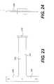
- FIG. 23is a front view of an extension arm of the camper of FIG. 11 .
- FIG. 24is a side view of an extension arm of the camper of FIG. 11 .
- FIG. 25is a side elevational view of another embodiment of an in-line jack constructed in accordance with principles of the present disclosure.
- FIG. 26is a side elevational view of the in-line jack as in FIG. 25 , but with an extendable shaft of a jack post of the in-line jack in an extended position.
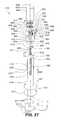
- FIG. 27is a partially exploded side view, partially in section, of the in-line jack of FIG. 25 .
- FIG. 28is a side elevational view of a drive assembly, partially in section, and a fragmentary side view, in section, of a jack post of the in-line jack of FIG. 25 .
- FIG. 29is a perspective view of an embodiment of a planetary gearbox, a coupling mechanism, and a crankshaft for an in-line jack constructed in accordance with principles of the present disclosure.
- FIG. 30is a perspective view of the planetary gearbox, the coupling mechanism, and the crankshaft as in FIG. 29 , but with the coupling mechanism in a decoupled position.
- FIG. 31is a fragmentary side view, in section, of an extendable shaft of a jack post and a fragmentary side view of a jackscrew assembly suitable for an in-line jack constructed in accordance with principles of the present disclosure.
- FIG. 32is a perspective view of an embodiment of a drive assembly suitable for an in-line jack constructed in accordance with principles of the present disclosure.
- FIG. 33is an end view of the drive assembly of FIG. 32 .
- FIG. 34is a cross-sectional view taken along line 34 - 34 in FIG. 33 .
- an embodiment of a pick-up truck camper 100can be configured to mount onto a vehicle 102 such as, for example, a pick-up truck.
- the camper 100may rest in the flat bed of the truck 102 and include an overhang 104 that extends over the cabin 106 of the truck 102 .
- the camper 100may include a first jack 110 , a second jack 112 , a third jack 114 , and a fourth jack 116 .
- the jacks 110 , 112 , 114 , 116may be used to raise the camper 100 off of the truck 102 so that the truck 102 may drive out from underneath the camper 100 .
- the jacks 110 , 112 , 114 , 116may also be used to lower the camper 100 onto the truck 102 , when the truck 102 is positioned below the camper 100 . Once the camper 100 is properly mounted on the truck 102 , the jacks 110 , 112 , 114 , 116 may be retracted so that the truck 102 may maneuver with the camper 100 securely mounted on the truck 102 , as shown in FIG. 1 .
- the pick-up truck camper 100further comprises a first sidewall 120 , a second sidewall 122 , a front wall 124 , and a rear wall 126 covering a frame 140 (see FIG. 2 ).
- the camper 100may also include a top wall 128 and a bottom wall 130 .
- the walls 120 , 122 , 124 , 126 , 128 , 130define the exterior 134 of the camper 100 .
- the wallscan be mounted to the frame 140 of the camper 100 .
- the frame 140can be located inside the exterior of the camper 100 .
- the first sidewall 120may have a double-walled construction and may be comprised of an outer wall 142 , which constitutes the exterior 134 of the camper 100 , and an inner wall 144 .
- the outer wall 142 and the inner wall 144may be substantially planar to each other.
- the frame 140may also be disposed between the outer wall 142 and the inner wall 142 of the first sidewall 120 .
- the second sidewall, the front wall, the rear wall, the top wall, and the bottom wallmay be similarly constructed as the first sidewall 120 . Accordingly, the second sidewall, the front wall, the rear wall, the top wall, and the bottom wall may also all have a double wall construction including an inner wall and outer wall.
- the framemay be disposed between the inner walls and the outer walls of all the camper walls.
- the first jack 110may be disposed inside the first sidewall 120 .
- the second jack 112may be disposed inside the second sidewall 122 .
- the third jack 114 and the fourth jack 116may be disposed inside the first and second sidewalls 120 , 122 , respectively.
- the sidewalls 120 , 122may be substantially planar such that the internal and external walls of the sidewalls 120 , 122 do not bulge in order to accommodate the jacks 110 , 112 , 114 , 116 .
- the internal walls of the sidewalls 120 , 122can include a bulged area or an unevenness to accommodate one or more of the jacks 110 , 112 , 114 , 116 .
- the jacks 110 , 112 , 114 , 116can be completely or partially exposed such that they are visible from the interior of the camper.
- the first and second jacks 110 , 112may be disposed at the front 146 of the camper 100 and the third and fourth jacks 114 , 116 may be disposed at the rear 148 of the camper 100 .
- the frame 100may include a first corner post 150 , a second corner post 152 , a third corner post 154 , and a fourth corner post 156 .
- the first, second, third, and fourth jacks 110 , 112 , 114 , 116may be mounted to the first, second, third, and fourth corner posts 150 , 152 , 154 , 156 , respectively.
- the first, second, third, and fourth jacks 110 , 112 , 114 , 116may all be similarly configured and similarly mounted to the camper 100 . Accordingly, only the first jack 110 will be described in detail.
- the first jack 110may be mounted to the frame 140 at the first corner post 150 .
- the first corner post 150 and a first lower bar 158 of the frame 140may be disposed between the inner wall 144 and the outer wall 142 of the first sidewall 120 .
- the jack 110can be hidden from view except for those portions extending below the first sidewall 120 .
- the jack 110may have a tubular body 160 with first and second distal ends 162 , 164 .
- the jack 110may include an extendable shaft 166 disposed within the body 160 and extending out of the second distal end 164 of the body 160 .
- a foot 168may be located at a lower distal end 170 of the shaft 166 .
- the jack 110may include drive mechanics 176 internal to the body 160 .
- the internal mechanics 176operate to extend and retract the extendable shaft 164 out of and into the body 160 .
- the jack 110may include an electric motor 178 mounted at the first distal end 162 of the body 160 wherein the electric motor 178 drives the mechanics 176 .
- the mechanics 176may include gearing such as, for example, planetary gears, that translate the rotary motion of the motor's drive shaft 180 into linear motion of the extendable shaft 164 .
- the operatorcan operate the jack 110 from inside and/or outside the camper.
- the mechanics 176 of the jack 110may also be driven manually by a crankshaft.
- the jack 110includes a crankshaft port 184 for receiving the operating end of a crankshaft.
- the crankshaft port 184may extend through the outer wall 142 of the first sidewall 120 so that an operator may operate the jack 110 from outside the camper with a crankshaft.
- the jack 110can be adapted such that the operator can operate the jack 110 with a crankshaft from either inside or outside the camper.
- the jackhas a diameter 188 that is sufficiently small so that the jack 110 may be disposed within the first sidewall 120 .
- the jack 110may have a diameter 188 of 2.25 inches (6.67 cm). In another embodiment, the jack may have a diameter 188 of between 1.75 inches (4.45 cm) and 3.00 inches (7.62 cm).
- the first jack 110may be attached to the corner post 150 by a strap 190 with a first end 192 and a second end 194 .
- the strap 190may wrap around the jack 110 while the first end 192 and the second end 194 may be bolted to the corner post 150 , thereby securing the jack 110 to the corner post 150 .
- the strap 190may mount the first jack 110 to the corner post 150 by tightly surrounding the jack 110 .
- the strap 190may be a two inch wide band of 16 gauge steel.
- the first jack 110may also be mounted to the frame 140 at a lower bar 158 of the frame 140 .
- the lower bar 158may have a hole 196 that passes therethrough.
- the jack 110may pass through the hole 196 in the bar 158 .
- the jack 110may include a mounting plate 200 welded to the jack 110 below the lower bar 158 .
- the mounting plate 200may be bolted to the underside of the lower bar 158 , thereby securing the jack 110 to the lower bar 158 .
- the mounting plate 200may include a center hole 202 through which the jack passes.
- the mounting plate 200may further include four bolt holes 202 , 204 , 206 , and 208 that pass therethrough. Referring to FIG. 6 , the bolt holes may receive bolts 212 , 214 , 216 , 218 to secure the jack 110 to the underside of the lower bar 158 .
- FIG. 10there is shown the frame 250 of another embodiment of a pick-up truck camper 252 .
- the third jack 254 and the fourth jack 256are disposed inside the rear wall such that they are aligned between the third corner post 260 and the fourth corner post 264 .
- the camper 300may comprise a first sidewall 302 , a second sidewall 304 , a front wall 306 , a rear wall 308 , a top wall 310 , and a bottom wall 312 , wherein the walls cover a frame.
- Each wall 302 , 304 , 306 , 308 , 310 , 312 of the campermay have an inner wall and an outer wall.
- the campermay include a first jack 320 and a second jack 322 located at the front 324 of the camper 300 .
- the camper 300may further include a third jack 326 and a fourth jack 328 located at the rear 330 of the camper 300 .
- the first jack 320may be a pull-out jack.
- the first jack 320may be movable between a first position, shown in FIG. 11 , in which the jack 320 is disposed inside the first sidewall 302 and a second position, shown in FIG. 13 , in which the jack 320 extends out from the first sidewall 302 .
- the second jack 322may also be a pull-out jack movable between a first position, shown in FIG. 12 , in which the jack is disposed inside the second sidewall 304 and a second position, shown in FIG. 14 , in which the jack 322 extends out from the second sidewall 304 .
- the first and second jacks 322 , 324may extend out in order to accommodate the rear end of a pick-up truck that may be wider than the distance 334 between the first and second jacks 320 , 322 when the jacks 320 , 322 are in their respective first positions.
- the first and second jacks 320 , 322may extend out to separate by a distance 336 .
- the camper 300may posses the advantageous qualities of a camper 300 with first and second jacks 320 , 322 that are internal to the sidewalls 302 , 304 of the camper 300 , while being compatible to use with trucks of various widths, including those with large widths. Referring to FIGS.
- the distance 336 between the first and second jacks 320 , 322may be at least eight inches greater when the jacks 320 , 322 are both in their respective second positions than the distance 334 between the jacks 320 , 322 when the jacks 320 , 322 are in their respective first positions. In other embodiments, the distance 336 between the first and second jacks 320 , 322 may be at least twelve inches greater when the jacks 320 , 322 are both in their respective second positions than the distance 334 between the jacks 320 , 322 when the jacks 320 , 322 are in their respective first positions.
- the first jack and the second jack 320 , 322may be similarly configured and similarly mounted to the pick-up truck camper. Accordingly, only the first jack 320 will be described in detail. Referring to FIG. 15 , the first jack 320 may be similarly configured to the first jack 110 of FIG. 3 , but the jack 320 may include a different mounting and additional components.
- the jack 320may include a wall portion 340 on the outer side of the jack 320 .
- the first sidewall 302 of the camper 300may include a recess 342 which is configured to receive the first jack 320 when the jack 320 is in the first position.
- the wall portion 340may be consistent with the outer wall 344 of the first sidewall 302 such that when the jack 320 is in the first position inside the recess 342 , the wall portion 340 will be flush with and blend in with the first sidewall 302 of the camper 300 , as shown in FIG. 11 .
- the first jack 320may also include a flange 346 disposed on the inner side of the jack 320 .
- the flange 346may be attached to the first distal end 348 of an extension arm 350 .
- the first distal end 348 of the extension arm 350may comprise a vertical bar 352 to which the flange 346 may be bolted.
- the extension arm 350may be slidably engaged with a channeled member 356 , the channeled member 356 being disposed proximate the recess 342 within the camper 300 .
- the channeled member 356may generally be a walled housing including a passageway 358 , the passageway 358 extending from a first opening 360 to a second opening 362 .
- the body portion 364 of the extension arm 350may pass through the passageway 358 such that the first distal end 348 of the extension arm 350 is located on a first side 366 of the channeled member 356 and a second distal end 370 of the extension arm 350 is located on a second side 368 of the channeled member 356 .
- the second distal end 370 of the extension arm 350may include a plate 372 .
- the vertical bar 352 and the plate 372 of the extension arm 350may each be larger than the first and second openings 360 , 362 , respectively, in at least one dimension. Accordingly, the vertical bar 352 and the extension plate 372 may be physically prevented from entering the channeled member 356 , thereby retaining the extension bar 350 in the passageway 358 .
- the channeled member 356may include a first pair 374 of ribs 376 , 378 on an upper wall 380 and a second pair 382 of ribs 384 , 386 on a lower wall 388 . There is a first gap 390 between the first pair 374 of ribs 376 , 378 and a second gap 392 between the second pair 382 of ribs 384 , 386 . The first and second gaps 390 , 392 may align to form a channel 394 for receiving the extension arm 350 , as shown in FIG. 16 . Referring to FIG. 20 , the channeled member 356 may be mounted on an I-beam member 400 .
- the I-beam member 400may include a plurality of bolt holes 402 , 404 , 406 , 408 to receive bolts. Referring to FIG. 15 , the bolts may bolt the I-beam to an internal surface 410 of the camper.
- the extension arm 350may be slidably disposed within the channel 394 of the channeled member 356 . Accordingly, the jack 320 may travel between the first position and the second channel depending upon where the extension 350 is along its path of travel within the channeled member 356 .
- the jack 320may be within its first position wherein the wall portion 340 is aligned with the exterior 344 of the camper 320 .
- the jack 320may be in the second position with the jack 320 fully extended out from camper 300 .
- the extension arm 350may travel within the channeled member 356 to position the jack 320 to any point between the first and second position.
- the wall portion 340 of the jack 320may include a handle 420 .
- An operatormay use the handle 420 to move the jack 320 between the first position and the second position.
- Thisis possible because the channel 394 of the channeled member 356 is configured to permit the sliding of the extension arm 350 relative to the channeled member.
- the channeled membermay be configured such that there is minimal friction between the extension arm 350 and the channel 394 .
- the channel 394may be narrow enough to ensure that the extension arm 350 travels a straight path relative to the channel 394 , wherein the roll, yaw, and pitch is restricted by the fit of the extension arm 350 within the channel 394 .
- the path of travel of the extension arm 350may also be substantially perpendicular to the outer wall 320 of the camper 300 . Accordingly, the jack 320 can consistently leave from and return to the recess 342 as it is moved between the first and second positions. In other embodiments the jack may be moved between the first position and the second position by other means such as, for example, hydraulics or an electrical motor.
- the second jack 322may be mounted to the camper in a mirror image of the first jack 320 . Accordingly, the jacks 320 , 322 may be moved towards and away from each other in order to manipulate the distance between the first and second jacks 320 , 322 .
- the first jack 320 and the second jack 322may be mounted independently from one another so that the positionings of the first jack 320 and the second jack 322 are independent of each other.
- the first and second jacksmay be mounted to the camper by a common mounting system. In one embodiment, the positioning of the first and second jacks may be correlated.
- the first and second jackscan be mounted on a pivot to swing out away from the camper side to increase the distance between the jacks to define a wider pickup truck entry.
- the jack 410includes a jack post 412 and an in-line drive assembly 414 .
- the jack post 412includes a body 416 in the form of an outer tube and an extendable shaft or lift tube 418 in the form of an inner tube disposed within the body 416 .
- the jack post 412 and the in-line drive assembly 414define a longitudinal axis 420 of the in-line jack 410 .
- the outer tubular body 416includes first and second ends 424 , 425 .
- the body can 416can include a mounting flange 426 having a plurality of mounting holes 427 adapted to receive a respective fastener therethrough to secure the body 416 to a structure (such as a wheel-less camper for example).
- a structuresuch as a wheel-less camper for example.
- the in-line jack 410can be used to raise and lower the structure relative to a supporting surface upon which the lift tube rests via movement of the lift tube 418 .
- the extendable shaft 418has a lower distal end 430 that extends out of an opening 432 at the second end 425 of the outer tube 416 .
- a foot 434is located at the distal end 430 of the lift tube 418 .
- the extendable shaft 418is reciprocally movable along the longitudinal axis 420 relative to the body 416 over a range of travel between a retracted position ( FIG. 25 ), in which the distal end 430 of the extendable shaft 418 is disposed a first distance 437 from the first end 424 of the body 416 along the longitudinal axis 420 , and an extended position ( FIG. 26 ), in which the distal end 430 of the extendable shaft 418 is disposed a second distance 438 from the first end 424 of the body 416 along the longitudinal axis 420 .
- the second distance 438is greater than the first distance 437 .
- the in-line drive assembly 414is mounted to the first end 424 of the body 416 and is adapted to selectively move the extendable shaft or lift tube 418 with respect to the tubular body 416 such that the extendable shaft or lift tube 418 can be moved out of and into the body 416 over a range of travel between the extended position ( FIG. 26 ) and the retracted position ( FIG. 25 ).
- the in-line drive assembly 414is substantially aligned with the body 416 along the longitudinal axis 420 of the in-line jack 410 such that the drive assembly 414 extends substantially along the longitudinal axis 420 .
- the in-line drive assembly 414includes a motor 440 operably arranged with drive mechanics to selectively move the extendable shaft or lift tube 418 relative to the body 416 in an extending direction 444 ( FIG. 25 ) along the longitudinal axis 420 and in a retracting direction 444 ( FIG. 26 ) along the longitudinal axis 420 .
- the drive mechanicsare housed in a planetary gearbox 450 , a manual crank box 452 , and the jack post 412 .
- the manual crank box 452is mounted adjacent the first end 424 of the body 416 and also houses a coupler/de-coupler mechanism.
- the planetary gearbox 450is disposed between the motor 440 and the manual crank box 452 .
- a mounting collar 455is provided to secure elements of the drive assembly 414 to the jack post 412 .
- the body 416 and the planetary gear and motor assembly 466each have a generally cylindrical outer surface.
- the motor 440 , the planetary gearbox 450 , the manual crank box 452 , the body 416 , and the extendable shaft 418each has a generally cylindrical outer surface with an outer diameter equal to or less than about three inches.
- each element of the jack 410(except for the mounting collar 455 and the foot 434 , in some embodiments) is confined to a cylindrical space no greater than about three inches in diameter.
- the motor 440 , the planetary gearbox 450 , the manual crank box 452 , and the body 416 and the extendable shaft 418 of the jack post 412are confined to a cylindrical space no greater than about three inches in diameter.
- the motor 440 , the planetary gearbox 450 , the manual crank box 452 , and the body 416 and the extendable shaft 418 of the jack post 412are substantially aligned with each other and are confined within a transverse cross-sectional area taken along a plane 457 perpendicular to the longitudinal axis 420 of the in-line jack 410 that does not exceed about nine square inches.
- the motor 440 , the planetary gearbox 450 , the manual crank box 452 , and the body 416 and the lift tube 418 of the jack post 412are disposed within a square-shaped cross-sectional area having a side equal to about three inches.
- the size and shape of the elements of the in-line jack 410can be varied.
- the motor 440can be any suitable motor, such as a reversible electrical motor.
- the motoris a 6000 rpm, 12 volt DC, reversing motor.
- an electric circuit breaker clutch 458can be provided.
- the circuit breaker clutchis a 30 amp electric circuit breaker clutch.
- the drive mechanics of the in-line drive assembly 414include a jackscrew assembly 460 , a drive shaft 462 , a planetary gear system 464 of a planetary gear and motor assembly 466 , a crankshaft 468 , and a coupling mechanism 470 .
- the drive shaft 462is operably arranged with the jackscrew assembly 460 .
- the planetary gear system 464is operably arranged with the drive shaft 462 .
- the crankshaft 468is adapted to manually operate the jackscrew assembly 460 via selective interaction with the drive shaft 462 .
- the coupling mechanism 470is adapted to selectively alternately couple the planetary gear system 464 with the drive shaft 462 and the crankshaft 468 with the drive shaft 462 .
- the planetary gear system 466is housed in the planetary gearbox 450 .
- the coupling mechanism 470 and the crankshaft 468are housed in the manual crank box 452 .
- the first and second ends 424 , 425 of the body 416 of the jack post 412define respective openings 474 , 475 in communication with an interior cavity 477 .
- the extendable shaft 418is movably disposed within the interior cavity 477 of the outer tube 416 .
- the extendable shaft 418telescopes in the tubular body 416 via the jackscrew assembly 460 .
- the jackscrew assembly 460is disposed within the interior cavity 477 of the tubular body 416 and an interior cavity 479 of the extendable shaft or lift tube 418 .
- the jackscrew assembly 460is operably arranged with the body 416 and the extendable shaft 418 to selectively move the extendable shaft 466 with respect to the body 416 .
- the jackscrew assembly 460is attached to both the body 416 and the extendable shaft 418 .
- the jackscrew assembly 460is adapted to selectively move the extendable shaft 418 relative to the body 416 over a range of travel between the extended position ( FIG. 26 ) and the retracted position ( FIG. 25 ).
- the jackscrew assembly 460is adapted to move the extendable shaft 418 relative to the outer body 416 along the longitudinal axis 420 in the retracting direction 446 so that the shaft 418 moves toward the retracted position and along the longitudinal axis 420 in the extending direction 444 so that the shaft 418 moves toward the extended position.
- the jackscrew assembly 460includes a threaded screw 490 , which is supported by the body 416 and extends along the longitudinal axis 420 , and a nut 492 , which is secured to the extendable shaft 418 .
- the screw 490is threadingly engaged with the nut 492 .
- the screw 490is centrally located axially with respect to the body 416 and the extendable shaft 418 and extends along the longitudinal axis 420 within the interior cavity 477 of the body 416 from a mounting plate 494 disposed adjacent the first end 424 of the body 416 .
- the mounting plate 494is fixedly connected to the body 416 by any suitable means, such as by being welded thereto, for example.
- the screw 490is rotatably movable about its longitudinal axis with respect to the mounting plate 494 by means of a bearing 496 .
- the bearing 496is mounted to the mounting plate 494 and is fixedly disposed within the interior cavity 477 of the body 416 along the longitudinal axis 420 .
- the screw 490extends through the bearing 496 .
- the screw 490interacts with the bearing 496 such that the screw 490 is rotatable about its longitudinal axis and constrained from translating along its longitudinal axis with respect to the bearing 496 .
- the screw 490includes a drive connector 498 which is adapted to engagingly receive a distal output end 500 of the drive shaft 462 such that rotation of the drive shaft 462 in one direction rotates the screw 490 in the same direction.
- the drive connector 498is connected to an upper end portion 502 of the screw 490 which extends through the mounting plate 494 .
- the screw 490is threadingly engaged with the nut 492 which is mounted to the extendable shaft 418 .
- the nut 492is suitably supported at an upper end 510 of the extendable shaft 418 on an indented portion 512 so that the nut 492 is constrained from rotating and translating with respect to the extendable shaft 418 (see FIG. 34 also).
- a screw or other fastenercan be secured to the upper end 510 of the extendable shaft 418 and the nut 492 through an anti-rotation bore 513 to rotatively couple the nut 492 to the extendable shaft 418 such that relative rotation therebetween is constrained.
- the nut 492is threadingly engaged with the screw 490 such that rotation of the screw 490 in a first direction 514 about the longitudinal axis 420 moves the extendable shaft 418 in the extending direction 444 away from the first end 474 of the body 416 and such that rotation of the screw 490 in a second direction 515 moves the shaft in the retracting direction 446 toward the first end 474 of the body 416 .
- the screw 490is turned in a clockwise direction to move the extendable shaft or lift tube 418 with respect to the body 416 in the extending direction 444 .
- the screw 490is turned in a counterclockwise direction to move the extendable shaft or lift tube 418 with respect to the body 416 in the retracting direction 446 .
- the drive shaft 462includes an input end 520 that is selectively operably arranged with the planetary gear system 464 and the distal output end 500 which is engaged with the drive connector 498 of the screw 490 of the jackscrew assembly 460 .
- the planetary gear and motor assembly 466acts upon the input end 520 of the drive shaft 462 to turn the drive shaft 462 which in turn acts upon the screw 490 of the jackscrew assembly 460 .
- the drive shaft 462is operably arranged with the jackscrew assembly 460 to turn the screw 490 in the first direction (clockwise) 514 and the second direction (counterclockwise) 515 .
- the planetary gear and motor assembly 466includes the motor 440 and the planetary gear system 464 .
- the planetary gear and motor assembly 466is mounted to the body 416 via the manual crank box 452 and the mounting collar 455 in the illustrated embodiment. In other embodiments, the planetary gear and motor assembly 466 can be mounted to the body 416 by other means.
- the planetary gear and motor assembly 466is substantially axially aligned with the body 416 .
- the planetary gear and motor assembly 466is substantially parallel to the longitudinal axis 420 .
- the planetary gear system 464is adapted to selectively rotate the drive shaft 462 .
- the motor 440is operably arranged with the planetary gear system 464 and is adapted to selectively drive the planetary gear system 464 to rotate the drive shaft 462 in either the first direction 514 or the second direction 515 , which opposes the first direction 514 , about the longitudinal axis 420 .
- the planetary gear system 464which is shown in schematic form in FIG. 27 , can be any suitable gear system, such as one having a 30:1 gear ratio.
- the motor 440 , the planetary gear system 464 , and the drive shaft 462are adapted to selectively move the jackscrew assembly 460 such that the extendable shaft 418 is selectively movable with respect to the body 416 in the extending direction 444 and the retracting direction 446 .
- the planetary gear and motor assembly 466is operably arranged with the drive shaft 462 to selectively turn the screw 490 in the first direction (e.g., clockwise) 514 about the longitudinal axis 420 to extend the lift tube or extendable shaft 418 in the extending direction 444 relative to the body 416 and in the second direction 515 , which opposes the first direction (e.g., counterclockwise), about the longitudinal axis 420 to retract the lift tube or extendable shaft 418 in the retracting direction 446 relative to the outer tube.
- first directione.g., clockwise
- the screw 490in the first direction (e.g., clockwise) 514 about the longitudinal axis 420 to extend the lift tube or extendable shaft 418 in the extending direction 444 relative to the body 416 and in the second direction 515 , which opposes the first direction (e.g., counterclockwise), about the longitudinal axis 420 to retract the lift tube or extendable shaft 418 in the retracting direction 446 relative to the outer
- the components of the in-line drive assembly 414 and the jack post 412are substantially aligned with each other.
- the illustrated jackscrew assembly 460 , the drive shaft 462 , the planetary gear system 464 , and the motor 440are concentrically arranged about the longitudinal axis 420 .
- the body 416 and the planetary gear and motor assembly 466are aligned such that those components of the in-line jack 410 have an outer diameter equal to or less than about three inches.
- the manual crank box 452is adjacent the first end 424 of the body 416 .
- the manual crank box 452is disposed between the planetary gearbox 450 and the jackscrew assembly 460 .
- the manual crank box 452houses the crankshaft 468 which is adapted to manually selectively drive the jackscrew assembly 460 via interaction with the drive shaft 462 .
- the manual crank box 452includes a crankshaft port 530 through which the crankshaft 468 extends.
- crank drive stub 532 of the crankshaft 468is disposed outside the manual crank box 452 and has a hexagonal shape suitable for being driven by a conventional tool, such as a lug wrench, socket wrench, pliers, drill, etc.
- the crankshaft 468includes a drive gear 534 mounted to a distal end 536 thereof and disposed within the manual crank box 452 .
- the drive gear 534 of the crankshaft 468comprises a bevel gear.
- the manual crank box 452also houses the coupling mechanism 470 which is adapted to selectively disengage the drive shaft 462 from the planetary gear system 464 and engage the crankshaft 468 with the jackscrew assembly 460 via the drive shaft 462 .
- the coupling mechanism 470includes a decoupling rod 540 , a driven gear 542 disposed concentrically about the drive shaft 462 and movably disposed with respect to the drive gear 534 of the crankshaft 468 , and a spring 544 disposed about the drive shaft 462 and adapted to bias the driven gear 542 of the drive shaft 462 to move out of engaging relationship with the drive gear 534 of the crankshaft 468 .
- the coupling mechanism 470is movable over a range of travel between a coupled position and a decoupled position.
- the coupling mechanism 470When the coupling mechanism 470 is in the coupled position (as in FIGS. 27 and 29 ), the planetary gear system 464 and the drive shaft 462 are in operable arrangement with each other such that movement of the gears of the planetary gear system 464 via the motor 440 moves the drive shaft 462 .
- the coupling mechanism 470is in the coupled position (as in FIGS. 27 and 29 )
- the driven gear 542 of the drive shaft 462is disengaged from the drive gear 534 of the crankshaft 468 .
- the decoupling rod 540includes an operating end 546 disposed outside of the manual crank box 452 , a straight body segment 548 , and a decoupling end 550 disposed within the manual crank box 452 .
- the decoupling rod 540extends through a coupling mechanism port 552 in the manual crank box 452 .
- the operating end 546 and the decoupling end 550can comprise bent segments that are in non-parallel relationship with the straight body segment 548 .
- the operating end 546is adapted to be gripped by a user to rotate the decoupling rod 540 to move the coupling mechanism 470 between the coupled position and the decoupled position.
- the decoupling end 550is adapted to engage the driven gear 542 disposed about the drive shaft 462 .
- the coupling mechanism 470When the coupling mechanism 470 is in the decoupled position, the decoupling end 550 engages the driven gear 542 such that the driven gear 542 of the drive shaft 462 is moved into enmeshing engagement with the drive gear 534 of the crankshaft 468 .
- the coupling mechanism 470can implement a different design and/or structure which is adapted to selectively alternately couple the planetary gear system 464 with the drive shaft 462 and the crankshaft 468 with the drive shaft 462 .
- crankshaft 468 and the drive shaft 462are in non-parallel relationship with each other.
- the crankshaft 468 and the drive shaft 462are substantially perpendicular to each other.
- the driven gear 542 of the drive shaft 462comprises a bevel gear which is configured to enmeshingly engage with the drive gear 534 of the crankshaft.
- the crankshaft 468 and the drive shaft 462can have a different orientation with respect to each other and the drive gear 534 and the driven gear 542 can have different complementary configurations.
- the spring 544is disposed about the drive shaft 462 between the driven gear 542 of the drive shaft 462 and a bearing 560 disposed about the drive shaft 462 .
- the drive shaft 462interacts with the bearing 560 such that the drive shaft 462 is rotatable about its longitudinal axis and constrained from translating along its longitudinal axis with respect to the bearing 560 .
- the bearing 560is suitably supported by the manual crank box 452 or other structure such that the bearing 560 is constrained from translating along the longitudinal axis 420 of the in-line jack 410 with respect to the planetary gear system 464 .
- the spring 544is adapted to bias the coupling mechanism 470 to the coupled position wherein the drive gear 534 of the crankshaft 468 and the driven gear 542 of the drive shaft 462 are disengaged.
- the coupling mechanism 470when the coupling mechanism 470 is moved to the decoupled position (as in FIG. 30 ), the coupling mechanism 470 disengages the drive shaft 462 from the planetary gear system 464 and moves the driven gear 542 of the drive shaft 462 into engaging relationship with the drive gear 534 of the crankshaft 468 .
- the crankshaft 468can be rotated using conventional tools, for example, in a first direction 564 and an opposing second direction 565 to turn the drive shaft in the first direction 514 and the second direction 515 , respectively, about the longitudinal axis 420 of the in-line jack 410 .
- the crankshaft 468When the crankshaft 468 is turned, the drive gear 534 rotates in the corresponding direction.
- the enmeshed driven gear 542turns in response to the movement of the drive gear 534 .
- the driven gear 542is rotatively coupled with the drive shaft 462 such that rotating the driven gear 542 rotates the drive shaft 462 .
- the crankshaft 468can be turned in the counterclockwise direction (facing the input end of the crankshaft) 564 to turn the drive shaft in the first (clockwise) direction 514 and turned in the clockwise direction (facing the input end of the crankshaft) 565 to turn the drive shaft in the second (counterclockwise) direction 515 .
- a bearing 570is disposed about the decoupling rod 540 .
- the decoupling rod 540interacts with the bearing 570 such that the decoupling rod 540 is rotatable about a longitudinal axis defined by the straight body segment 548 of the decoupling rod 540 and constrained from translating along its longitudinal axis with respect to the bearing 570 .
- the driven gear 542can include a collar 572 that is adapted to engagingly couple with an output end 575 of the planetary gear system 464 .
- the driven gear 542 and the collar 572provide a generally T-shaped profile.
- the collar 572 and the output end 575 of the planetary gear system 464can have complementary shapes such that the output end 575 is rotatively coupled with the collar 572 of the driven gear 542 when the coupling mechanism 470 is in the coupled position.
- the input end 520 of the drive shaft 462 and at least some interior portion of the driven gear 542can be configured such that they have complementary shapes so that the drive shaft 462 is rotatively coupled to the planetary gear system 464 when the coupling mechanism 470 is in the coupled position and in the decoupled position.
- the output end 575 of the planetary gear system 464is rotatively coupled with the collar 572 of the driven gear 542 and a portion of an interior surface of the driven gear 542 (including the collar 572 in some embodiments) is rotatively coupled with the drive shaft 462 such that rotation of the planetary gear system 464 rotates the drive shaft 462 .
- the userturns the operating end 546 of the decoupling rod 540 to move the coupling mechanism 470 to the decoupled position (as in FIG. 30 ).
- Turning the operating end 546 of the decoupling rod 540rotates the decoupling end 550 of the decoupling rod 540 which in turn acts upon the driven gear 542 of the drive shaft 462 such that the driven gear 542 of the drive shaft 462 moves along the longitudinal axis of the drive shaft 462 relative to and toward the drive gear 534 of the crankshaft 468 and relative to and away from the planetary gear system 464 .
- the operating end 546 of the decoupling rod 540can be so turned until the coupling mechanism 470 is moved to the decoupled position wherein the driven gear 542 of the drive shaft 462 is meshingly engaged with the drive gear 534 of the crankshaft 468 and the output end 575 of the planetary gear system 464 is disengaged from the input end 520 of the drive shaft 462 (see FIG. 30 ).
- the collar 572 of the driven gear 542is disengaged from the output end 575 of the planetary gear system 464 .
- the usermaintains the operating end 546 of the decoupling rod 540 in position so that the coupling mechanism 470 is in the decoupled position.
- the usercan rotate the crankshaft 468 using conventional tools in either the first direction 564 or the opposing second direction 565 to turn the drive shaft 462 through the interaction of the enmeshed drive gear 534 and the driven gear 542 , which is rotatively coupled with the drive shaft 462 .
- the drive shaft 462in turn, rotates in the first direction 514 and the second direction 515 , respectively, about the longitudinal axis 420 of the in-line jack 410 .
- the spring 544acts upon the driven gear 542 about the drive shaft 462 and urges it to move along the longitudinal axis 420 relative to and away from the drive gear 534 of the crankshaft 468 such that the coupling mechanism 470 returns to the coupled position (as in FIG. 29 ) in which the planetary gear system 464 is operably arranged with the drive shaft 462 to turn the drive shaft 462 when the planetary gear system 464 rotates and the drive gear 534 of the crankshaft 468 is disengaged from the driven gear 542 of the drive shaft 462 .
- the collar 572 of the driven gear 542is rotatively coupled with the output end of the planetary gear system 464 to rotatively couple the planetary gear system 464 with the drive shaft 462 .
- the mounting collar 455is mounted to the manual crank box 452 , such as, by being welded thereto, for example.
- the mounting collar 455defines an internal chamber 580 .
- the mounting collar 455is adapted to be removably mounted to the tubular body 416 .
- the mounting collar 455includes a plurality of mounting holes 582 through which a respective fastener can extend to secure the mounting collar 455 to the body 416 of the jack post 412 .
- the distal output end 500 of the drive shaft 462is disposed within and adjacent the internal chamber 580 of the mounting collar 455 .
- the distal output end 500 of the drive shaft 462includes a pin 586 projecting outwardly from opposing sides of the drive shaft 462 (see FIG. 34 also).
- the drive connector 498 of the screw 490 of the jackscrew assembly 460defines a socket 588 adapted to receive the distal output end 500 of the drive shaft 462 therein.
- the drive connector 498can include a slotted end 590 that is adapted to receive therein the pin 586 projecting from the drive shaft 462 .
- the inter-engagement of the pin 586 and the slotted end 500 of the drive connector 498 of the screwprovide a positive connection therebetween such that the drive shaft 462 and the screw 490 of the jackscrew assembly 460 are rotatively coupled together.
- the in-line drive assembly 614includes a drive shaft 662 , a planetary gear and motor assembly 666 , a crankshaft 668 , and a coupling mechanism 670 .
- the crankshaft 668 and the coupling mechanism 670are housed in a manual crank box 652 .
- a mounting collar 655is attached to the manual crank box.
- the drive shaft 662 of the in-line drive assembly 614 in FIG. 32is similar to the drive shaft 462 of the in-line drive 414 in FIGS. 25-27 with respect to its construction and function.
- the planetary gear and motor assembly 666includes a motor 640 with an electric circuit breaker clutch 658 , a planetary gear system housed in a planetary gearbox 650 , and a mounting plate 673 disposed between the motor 640 and the planetary gearbox 650 to facilitate the assembly of the in-line drive assembly 614 .
- the mounting plate 673includes a plurality of mounting holes 676 through which a respective fastener can extend to secure the manual crank box 652 to the planetary gear box 650 .
- the mounting plate 673has a generally square shape. In some embodiments, the length of the sides of the mounting plate 673 is equal to or less than three inches.
- the planetary gear and motor assembly 666 of the in-line drive assembly 614 in FIG. 32is similar in other respects to the planetary gear and motor assembly 466 of the in-line drive 414 in FIGS. 25-27 with respect to its construction and function.
- the manual crank box 652includes a crankshaft port 730 through which the crankshaft 668 extends and a coupling mechanism port 752 through which a decoupling rod 740 of the coupling mechanism 670 extends.
- the manual crank box 652is generally cube-shaped and includes a top end plate 681 and a bottom end plate 683 that are substantially square-shaped. Fasteners can be secured to the mounting plate 673 of the planetary gear and motor assembly 666 and the top end plate 681 of the manual crank box 652 to attach the manual crank box 652 to the planetary gear and motor assembly 666 .
- the top and bottom end plates 681 , 683 of the manual crank box 652are substantially the same shape and size as the mounting plate 673 of the planetary gear and motor assembly 666 .
- the length of the sides of the top and bottom end plates of the manual crank boxis equal to or less than three inches.
- the crankshaft 668 and the coupling mechanism 670 of the in-line drive assembly 614 in FIG. 32are similar in other respects to the crankshaft 468 and the coupling mechanism 470 of the in-line drive 414 in FIGS. 25-27 , 29 , and 30 with respect to its construction and function.
- the mounting collar 655is generally cylindrical and is adapted to be secured to a suitable jack post have a jackscrew assembly therein adapted to be drivingly engaged with a distal output end 700 of the drive shaft 662 .
- the diameter of the mounting collar 655is equal to or less than three inches.
- the mounting collar 655includes a plurality of mounting holes 782 adapted to receive a respective fastener therethrough which connects the collar 655 to a body of a suitable jack post.
- the motor 640includes a pair of lead wires 791 , 792 adapted to electrically connect the motor 640 to an electrical power source.
- An operating end 746 of the decoupling rod 740extends outwardly beyond an input end or crank drive stub 732 of the crankshaft 668 .
- the drive shaft 662includes a includes a pin 786 adjacent the distal output end 700 of the drive shaft 662 .
- the pin 786projects radially outwardly from opposing sides of the drive shaft 662 .
- the pin 786can be adapted to be engaged with a slotted end of a suitable drive connector of a screw of a jackscrew assembly to provide a positive connection between the drive shaft 662 and the screw of the jackscrew assembly.
- jacks and their respective mountings and componentssuch as the coupling mechanism, for example, which have been described herein are merely exemplary embodiments.
- the desired features and functions of the above described jacksmay be realized by various other embodiments that employ different jack features, fastening means, mounting assemblies, motion control systems, or mechanical, electrical, and hydraulic systems and components.
Landscapes
- Engineering & Computer Science (AREA)
- Mechanical Engineering (AREA)
- Health & Medical Sciences (AREA)
- Public Health (AREA)
- Transportation (AREA)
- Vehicle Cleaning, Maintenance, Repair, Refitting, And Outriggers (AREA)
- Accommodation For Nursing Or Treatment Tables (AREA)
Abstract
Description
Claims (13)
Priority Applications (2)
| Application Number | Priority Date | Filing Date | Title |
|---|---|---|---|
| US13/281,062US8678471B2 (en) | 2007-01-19 | 2011-10-25 | In-line jack |
| US14/225,130US10894532B2 (en) | 2007-01-19 | 2014-03-25 | In-line jack |
Applications Claiming Priority (3)
| Application Number | Priority Date | Filing Date | Title |
|---|---|---|---|
| US11/655,562US7722110B2 (en) | 2007-01-19 | 2007-01-19 | Wheel-less pick-up truck camper with internal jacks |
| US12/331,111US8480158B2 (en) | 2007-01-19 | 2008-12-09 | Wheel-less pick-up truck camper with pull-out jacks |
| US13/281,062US8678471B2 (en) | 2007-01-19 | 2011-10-25 | In-line jack |
Related Parent Applications (1)
| Application Number | Title | Priority Date | Filing Date |
|---|---|---|---|
| US12/331,111Continuation-In-PartUS8480158B2 (en) | 2007-01-19 | 2008-12-09 | Wheel-less pick-up truck camper with pull-out jacks |
Related Child Applications (1)
| Application Number | Title | Priority Date | Filing Date |
|---|---|---|---|
| US14/225,130DivisionUS10894532B2 (en) | 2007-01-19 | 2014-03-25 | In-line jack |
Publications (2)
| Publication Number | Publication Date |
|---|---|
| US20120037862A1 US20120037862A1 (en) | 2012-02-16 |
| US8678471B2true US8678471B2 (en) | 2014-03-25 |
Family
ID=45564145
Family Applications (2)
| Application Number | Title | Priority Date | Filing Date |
|---|---|---|---|
| US13/281,062Active - Reinstated2027-01-31US8678471B2 (en) | 2007-01-19 | 2011-10-25 | In-line jack |
| US14/225,130ActiveUS10894532B2 (en) | 2007-01-19 | 2014-03-25 | In-line jack |
Family Applications After (1)
| Application Number | Title | Priority Date | Filing Date |
|---|---|---|---|
| US14/225,130ActiveUS10894532B2 (en) | 2007-01-19 | 2014-03-25 | In-line jack |
Country Status (1)
| Country | Link |
|---|---|
| US (2) | US8678471B2 (en) |
Cited By (12)
| Publication number | Priority date | Publication date | Assignee | Title |
|---|---|---|---|---|
| US20140008905A1 (en)* | 2010-12-21 | 2014-01-09 | Schaeffler Technologies AG & Co. KG | Support device for work vehicles |
| US20150137498A1 (en)* | 2013-11-21 | 2015-05-21 | Paul L. Klassy | Powered landing gear with cross-port disable valve travel limiter |
| US20160023641A1 (en)* | 2013-11-21 | 2016-01-28 | Paul L. Klassy | External Mid-Mount Drive For Powered Landing Gear With Cross-Port Disable Valve Travel Limiter |
| US20160107008A1 (en)* | 2011-11-01 | 2016-04-21 | Jay Thomas Hisel | Hand powered hydraulic rescue strut |
| US20170057472A1 (en)* | 2013-09-10 | 2017-03-02 | Clinton L. Jackson, SR. | Electronic interface control system for a pneumatic vehicle safety lift system |
| US9840235B2 (en)* | 2013-12-24 | 2017-12-12 | Hubert Koschinat | Telescopic support comprising a spindle, and driving said spindle by means of a crown wheel comprising an integrated thrust bearing for supporting loads |
| US9937902B2 (en) | 2013-11-21 | 2018-04-10 | Paul L. Klassy | Landing gear with cross-port disable valve and supplemental electronic limit switch travel limiter |
| US10894532B2 (en) | 2007-01-19 | 2021-01-19 | Rieco-Titan Products, Inc. | In-line jack |
| US11125156B2 (en)* | 2019-06-25 | 2021-09-21 | Yantai Jereh Petroleum Equipment & Technologies Co., Ltd. | Mobile power generation system |
| US11414308B2 (en)* | 2017-05-22 | 2022-08-16 | Hiab Ab | Stabilizer leg device |
| US11628697B2 (en)* | 2016-11-07 | 2023-04-18 | William K Chapin | Hydraulic gooseneck trailer coupler system and method |
| US11753991B2 (en) | 2019-06-25 | 2023-09-12 | Yantai Jereh Petroleum Equipment & Technologies Co., Ltd. | Intake-exhaust transport apparatus mobile power generation system and assembling method thereof |
Families Citing this family (11)
| Publication number | Priority date | Publication date | Assignee | Title |
|---|---|---|---|---|
| TR201807927T4 (en) | 2012-12-04 | 2018-06-21 | Jost Int Corp | Double speed parking stand with automatic passage. |
| JP6385369B2 (en)* | 2013-01-31 | 2018-09-05 | ラピスカン システムズ、インコーポレイテッド | Transportable safety inspection system |
| US9308894B2 (en)* | 2014-01-16 | 2016-04-12 | Robert H. Lusty | Fast adjust trailer jack |
| US11059461B2 (en) | 2014-02-12 | 2021-07-13 | Jost International Corp. | Electrically coupled powered landing gear |
| WO2015134170A2 (en) | 2014-02-12 | 2015-09-11 | Jost International Corp. | Powered landing gear |
| JP6671144B2 (en)* | 2014-10-30 | 2020-03-25 | 新和商事株式会社 | Track pad and rail support structure |
| KR102021826B1 (en)* | 2018-02-05 | 2019-09-17 | 엘지전자 주식회사 | A cleaner |
| US11926292B1 (en)* | 2019-09-27 | 2024-03-12 | Ricky Strogen | Motorized landing gear for a tractor trailer |
| US11807057B2 (en)* | 2019-10-01 | 2023-11-07 | Ted Hsutse Chen | Trailer jack device with a more efficient gear reduction ratio for improving a power drill efficiency |
| KR102293515B1 (en)* | 2020-05-29 | 2021-08-24 | 주식회사 대명테크 | Tung Jack for trailer |
| NL2037000B1 (en)* | 2024-02-09 | 2025-08-20 | Johan Van Gent Willem | Extension kit for a nose wheel assembly |
Citations (78)
| Publication number | Priority date | Publication date | Assignee | Title |
|---|---|---|---|---|
| US964394A (en) | 1909-10-11 | 1910-07-12 | Charles M Stuart | Lifting-jack. |
| US2837312A (en)* | 1954-10-04 | 1958-06-03 | J H Holan Corp | Automatic jack |
| US3022043A (en)* | 1960-09-16 | 1962-02-20 | Dewey S Weiss | Quick action jack |
| US3197054A (en) | 1962-09-28 | 1965-07-27 | Mahlon E Settem | Transfer mechanism for campers and like framed units |
| US3368839A (en) | 1966-03-04 | 1968-02-13 | Glen M Stewart | Expandable camper |
| US3414916A (en)* | 1967-11-29 | 1968-12-10 | James A. Martin | Amphibious camper apparatus |
| US3436774A (en) | 1968-01-09 | 1969-04-08 | William B Schmitz | Watercraft |
| US3507476A (en) | 1968-04-10 | 1970-04-21 | Winton J Bennett | Jack for camper |
| US3523698A (en) | 1968-10-03 | 1970-08-11 | Ralph Bishop | Levelling system for trailers and the like |
| US3580599A (en)* | 1969-05-02 | 1971-05-25 | Dodgen Ind Inc | Jack and tiedown system for a vehicle mounted camper |
| US3595527A (en)* | 1969-07-14 | 1971-07-27 | Atwood Vacuum Machine Co | Quickly retractable and extensible jack construction |
| US3640502A (en) | 1970-06-01 | 1972-02-08 | Colorado Leisure Products Inc | Cross drive for lift jack apparatus |
| US3679174A (en) | 1971-02-10 | 1972-07-25 | Richard W Boettcher | Jack or lift mechanism and drive therefor |
| US3689029A (en)* | 1971-03-29 | 1972-09-05 | Colorado Leisure Products Inc | Ratchet-type lift jack unit and lift method for camper bodies and the like |
| US3709467A (en)* | 1970-11-27 | 1973-01-09 | J Mann | Self contained adjustable support assemblies to support, raise, and lower a mobile living facility with respect to both a vehicle and the ground |
| US3758074A (en) | 1972-08-07 | 1973-09-11 | E Jeffries | Camper lifting system and removable jacks therefor |
| US3828379A (en) | 1973-06-01 | 1974-08-13 | B Walston | Camper converta boat |
| US3844535A (en)* | 1969-07-15 | 1974-10-29 | J Dorough | Portable electric automobile jack |
| US3909057A (en) | 1973-10-29 | 1975-09-30 | Joe M Guthry | Combination camper and boat trailer mechanism |
| US3984082A (en) | 1975-04-28 | 1976-10-05 | Boettcher Richard W | Self-stowing jack |
| US4044999A (en)* | 1976-10-29 | 1977-08-30 | Dodgen Industries, Inc. | Camper jack |
| US4176825A (en) | 1978-02-01 | 1979-12-04 | Schwebke Donald D | Jack device for trailers |
| US4176824A (en) | 1977-02-07 | 1979-12-04 | Richard Lewis | Lifting apparatus |
| US4238113A (en)* | 1979-11-16 | 1980-12-09 | Adams Vernon E | Jacking device |
| US4240334A (en) | 1977-12-28 | 1980-12-23 | United Hydraulics Corporation | Mechanically lockable hydraulic cylinder jack |
| US4247145A (en) | 1979-07-23 | 1981-01-27 | Groene Richard L | Cargo unit with support jack assemblies |
| US4254927A (en) | 1979-04-30 | 1981-03-10 | Stonhaus James H | Jacking plate for trailer and the like |
| US4483515A (en)* | 1982-08-26 | 1984-11-20 | Masco Corporation | Lifting jack and cover therefor |
| US4685695A (en) | 1985-12-16 | 1987-08-11 | Levee Robert C | Watertight, secured truck enclosure |
| US4754998A (en) | 1987-02-02 | 1988-07-05 | Lejuerrne Richard J | Catamaran-camper-trailer |
| US4784369A (en) | 1988-04-21 | 1988-11-15 | Bock Products, Inc. | Camper lift jack and hand crank |
| US4969631A (en)* | 1989-09-13 | 1990-11-13 | The Dometic Corporation | Vehicle jack |
| US5118082A (en) | 1990-06-28 | 1992-06-02 | B & L Corp. | Electrically operated screw-type jack |
| US5188379A (en) | 1990-10-19 | 1993-02-23 | Applied Mechanis, Inc. | Automatic leveling system for recreational vehicles |
| US5219429A (en) | 1992-08-10 | 1993-06-15 | Shelton Bill E | Hydra-lift system |
| US5273256A (en) | 1992-10-20 | 1993-12-28 | Atwood Industries, Inc. | Quick-to-ground camper jack |
| US5312119A (en) | 1991-10-24 | 1994-05-17 | Versa Technologies, Inc. | Vehicle leveling system with safety interlock |
| USD348966S (en) | 1993-06-14 | 1994-07-19 | Victor Guyton | Vehicle mounted hydraulic auto jack |
| US5348258A (en) | 1992-11-30 | 1994-09-20 | Rasmussen C Martin | Z-bracket camper jack mounting assembly |
| DE19508089A1 (en) | 1994-03-30 | 1995-10-05 | Friedrich Fischer | Jack for aligning shafts on vehicle trailers - has inner tube connected to foot, sliding threaded rod with operating handle and device for stopping relative sliding movement |
| US5542647A (en)* | 1995-03-20 | 1996-08-06 | Huetsch; Larry C. | Two-speed jack |
| US5553825A (en)* | 1992-11-30 | 1996-09-10 | Rasmussen; C. Martin | Mechanical camper jack |
| US5575493A (en)* | 1994-02-01 | 1996-11-19 | Schwartz; Charlie E. | Lifting mechanism for wheeled apparatus |
| US5680732A (en) | 1993-12-31 | 1997-10-28 | Skouras; Joseph Alexander | Lifting and shoring jack assembly |
| US5711561A (en) | 1996-04-09 | 1998-01-27 | Boysen; Richard L. | Bumper mountable camper stand |
| US5755430A (en) | 1997-03-06 | 1998-05-26 | Couch; Ernest C. | Trailer jack leveling adapter |
| US5848870A (en) | 1997-04-15 | 1998-12-15 | Smith Transportation Equipment, Inc. | Single person catering vehicle |
| US5934738A (en) | 1998-03-04 | 1999-08-10 | Welles; James F. | Collapsible room addition for a camper |
| US5984353A (en)* | 1997-07-02 | 1999-11-16 | Rasmussen; C. Martin | Quick-release arrangement for a camper jack system |
| US6071062A (en)* | 1998-07-01 | 2000-06-06 | Pods, Inc. | Apparatus for lifting, handling, and transporting a container |
| US6102468A (en) | 1997-10-27 | 2000-08-15 | General Plastics, Inc. | Convertible camping trailer |
| US6135525A (en)* | 1998-09-17 | 2000-10-24 | Amann; Robert Collins | Expandable portable shelter |
| US6142501A (en) | 1999-09-09 | 2000-11-07 | Fogo; Neil R. | Recreational vehicle jack remote control |
| US6170502B1 (en) | 1999-03-12 | 2001-01-09 | Jerome A. Pullen | Collapsible portable camper system |
| US6250650B1 (en) | 1996-12-17 | 2001-06-26 | Leland H. Douglas | Automatic fifth wheel loading and unloading system |
| US6267357B1 (en) | 2000-02-10 | 2001-07-31 | Fulton Performance Products, Inc. | Drop foot jack |
| US6283536B1 (en) | 2000-08-16 | 2001-09-04 | Engineers On Wheels Inc. | Pickup truck folding camper system |
| US20010052592A1 (en) | 1999-11-29 | 2001-12-20 | Alvarado Daniel V. | Low cost vehicle safety jack |
| US6517026B1 (en) | 2001-09-06 | 2003-02-11 | Leo Smith | Vertical take-off and landing vehicle for land, water and air transport |
| US6679542B1 (en) | 2002-12-12 | 2004-01-20 | Thomas Daniel Semotuk | Folding camper for pickup trucks |
| US6698810B1 (en) | 2002-09-23 | 2004-03-02 | David A. M. Lane | Telescoping, multifunction tailgate extender |
| US6712414B2 (en) | 2001-12-20 | 2004-03-30 | Floyd L. Morrow | Mobile, expandable structure, assembly support system |
| US6789361B1 (en) | 2001-07-11 | 2004-09-14 | Jason M. Spartz | Garage/carport for manufactured homes |
| US6893006B2 (en)* | 2003-02-18 | 2005-05-17 | Cequent Trailer Products, Inc. | Multi-speed drop leg mechanical jack for use with a trailer |
| US6895648B1 (en) | 2003-05-03 | 2005-05-24 | Michael J. Willett | Motor vehicle pneumatic jacklift system |
| US6926305B2 (en)* | 2002-05-10 | 2005-08-09 | Jeffrey Daniel | Air, electric and hydraulic landing gear jack |
| US7014238B2 (en) | 2004-03-02 | 2006-03-21 | Gonzalez Jaime Humberto Gutier | Automatically and reversibly transformable trailer-to-raised lookout platform |
| US7044445B1 (en) | 2003-12-19 | 2006-05-16 | Crawford Jerry L | Hydraulic-mechanical vehicle elevating system |
| US20060284146A1 (en) | 2005-06-16 | 2006-12-21 | Walt Perham | Camper stabilization system |
| US7198314B1 (en) | 2001-06-23 | 2007-04-03 | Edwards John A | Passenger cabin extension member |
| US20070152203A1 (en)* | 2001-01-12 | 2007-07-05 | Green E Paul | Method and apparatus for trailer jack mount |
| US7287798B2 (en) | 2005-03-18 | 2007-10-30 | Daimlerchrysler Corporation | Tailgate assembly and method of operating the same |
| US7311294B1 (en) | 2005-03-04 | 2007-12-25 | Yuhuan Top Sun Machinery Tool Co., Ltd. | Jack bar with extendable tubes and fixturing mechanism |
| US7325786B2 (en)* | 2003-02-18 | 2008-02-05 | Cequent Trailer Products, Inc. | Multi-speed drop leg mechanical jack for use with a trailer |
| US20080054598A1 (en)* | 2004-03-11 | 2008-03-06 | Richard Weber | Adjustable Trailer Coupling System |
| US20080174146A1 (en) | 2007-01-19 | 2008-07-24 | Rieco-Titan Products, Inc. | Wheel-less pick-up truck camper with internal jacks |
| US20090057633A1 (en)* | 2007-07-16 | 2009-03-05 | Russ Beck | Jack assembly |
| US20120247159A1 (en)* | 2011-03-30 | 2012-10-04 | Mathew Bradley Shelton | Anti-theft system for a camper |
Family Cites Families (150)
| Publication number | Priority date | Publication date | Assignee | Title |
|---|---|---|---|---|
| US2021733A (en) | 1934-09-10 | 1935-11-19 | Robert B Luker | Lifting means attachment for automobiles |
| US2167520A (en) | 1937-01-15 | 1939-07-25 | Bassick Co | Trailer coupling and support |
| US2232187A (en) | 1940-05-27 | 1941-02-18 | Fruehauf Trailer Co | Supporting leg structure for semitrailers |
| US2464890A (en) | 1944-06-19 | 1949-03-22 | Owen D Premo | Planetary drive gearing |
| US2499625A (en) | 1944-07-04 | 1950-03-07 | Trailmobile Company | Prop for trailers |
| US2674438A (en) | 1952-05-07 | 1954-04-06 | West Michigan Steel Foundry Co | Support for semitrailers |
| US2747422A (en) | 1952-10-30 | 1956-05-29 | Dayton Steel Foundry Co | Two-speed landing gear for trailers |
| US2885220A (en) | 1955-11-09 | 1959-05-05 | West Michigan Steel Foundry Co | Shock absorbing support for semi-trailer landing gear |
| US2959395A (en) | 1958-07-23 | 1960-11-08 | Robert A Strack | Semi-trailer landing gear power attachment |
| US3007677A (en) | 1959-09-21 | 1961-11-07 | West Michigan Steel Foundry Co | Landing gear for semi-trailers and the like |
| US3136527A (en) | 1961-09-12 | 1964-06-09 | William R Stokes | Electric landing gear |
| US3135135A (en) | 1962-03-05 | 1964-06-02 | West Michigan Steel Foundry Co | Reduction gear crank for semi-trailer landing gear legs and the like |
| BE657618A (en) | 1963-12-24 | |||
| US3288435A (en)* | 1964-06-17 | 1966-11-29 | Ernest W Starkey | Trailer with motorized jack assembly |
| US3338554A (en) | 1965-05-03 | 1967-08-29 | Frank T Gostomski | Screw actuated jack means |
| US3402915A (en) | 1966-08-01 | 1968-09-24 | Westran Corp | Power package for semi-trailer support |
| US3567271A (en) | 1966-08-19 | 1971-03-02 | Frank T Gostomski | Loading,unloading and leveling means for campers and the like |
| US3409272A (en) | 1967-02-13 | 1968-11-05 | Rasmussen Reed | Camper support including lift means |
| US3489428A (en) | 1967-06-01 | 1970-01-13 | Ward Mfg Inc | Stabilizing support for a camping trailer and the like |
| US3489395A (en) | 1967-08-24 | 1970-01-13 | Pullman Inc | Lubricated trailer prop |
| DE1926161A1 (en) | 1969-05-22 | 1970-12-10 | Haamann Winden Hebezeug | Supporting device, especially for semi-trailers |
| US3791664A (en) | 1970-08-27 | 1974-02-12 | Freightliner Corp | Self-leveler |
| US3764109A (en) | 1971-11-29 | 1973-10-09 | R Hollis | Jack |
| US3764162A (en) | 1971-12-21 | 1973-10-09 | Raymond Lee Organization Inc | Automatic landing gear device |
| CA983004A (en) | 1973-06-26 | 1976-02-03 | Karl H. Felsen | Independent jacking system for vehicles and the like |
| US3892141A (en) | 1973-11-19 | 1975-07-01 | Dayton Walther Corp | Landing gear with shaft detent clip retainer |
| US3861648A (en) | 1974-01-09 | 1975-01-21 | Pullman Inc | Two-speed trailer landing gear safety arrangement |
| US3904177A (en) | 1974-08-12 | 1975-09-09 | Westran Corp | Hydromechanical jack |
| US3927863A (en) | 1974-09-03 | 1975-12-23 | George Polsky | Transportable jack |
| US4129322A (en) | 1976-06-21 | 1978-12-12 | Kuntz Jr Martin | Support device for a trailer |
| US4097840A (en) | 1976-10-18 | 1978-06-27 | Chappelle Warner A | Automatic semi-trailer landing gear extension and retraction apparatus |
| NL7806588A (en) | 1977-06-29 | 1979-01-03 | Haamann Hebe Transport Jos | SUPPORT DEVICE FOR A TRAILER OR THE LIKE. |
| US4082249A (en) | 1977-07-11 | 1978-04-04 | Valdespino Joseph M | Recreational vehicle leveling and support system |
| US4187733A (en) | 1978-05-30 | 1980-02-12 | Dayton-Walther Corporation | Speed reduction mechanism for semi-trailer landing gear |
| US4216939A (en) | 1978-09-20 | 1980-08-12 | Valdespino Joseph M | Recreational vehicle leveling and support system |
| DE2851980C2 (en) | 1978-12-01 | 1982-07-01 | E.A. Storz Gmbh & Co Kg, 7200 Tuttlingen | Jack |
| DE2910210C2 (en) | 1979-03-15 | 1984-02-09 | E.A. Storz Gmbh & Co Kg, 7200 Tuttlingen | Jack |
| GB2077205B (en) | 1979-06-20 | 1983-03-23 | Busby Philip Victor | Drive mechanism for a vehicle trailer lifting gear |
| US4328989A (en) | 1980-04-21 | 1982-05-11 | Childers Roger B | Cover apparatus for the cargo bed of pickup trucks, travel, trailers and the like |
| US4316601A (en) | 1980-12-08 | 1982-02-23 | Sperry Corporation | Quick-adjusting jackstand apparatus |
| DE3119359C2 (en) | 1981-05-15 | 1983-02-24 | Jost-Werke GmbH, 6078 Neu Isenburg | Telescopic support device for heavy loads, in particular semi-trailers |
| US4466637A (en) | 1981-09-22 | 1984-08-21 | Nelson Carl A | Power drive mechanism for trailer landing gear |
| US4522375A (en) | 1982-12-27 | 1985-06-11 | Carmen Howell | Electrical lift for trailers |
| US4635904A (en) | 1984-09-17 | 1987-01-13 | A & E Systems, Inc. | Vehicle jack |
| US4741086A (en) | 1985-08-29 | 1988-05-03 | The B. F. Goodrich Company | Pneumatic lift jack |
| US4634144A (en) | 1985-11-01 | 1987-01-06 | Fruehauf Corporation | Sand shoe |
| US4903977A (en) | 1987-05-11 | 1990-02-27 | The Binkley Company | Landing gear for a vehicle |
| US4824136A (en) | 1987-05-11 | 1989-04-25 | The Binkley Company | Landing gear for a vehicle |
| DE3722643C1 (en) | 1987-07-09 | 1988-10-06 | Index Werke Kg Hahn & Tessky | Tool turret |
| US4863184A (en) | 1987-08-28 | 1989-09-05 | Daniel Mena | Tractor-trailer landing gear mechanism and method of using same |
| US4796864A (en) | 1987-10-26 | 1989-01-10 | Stallion Trailer Kits, Inc. | Spring loaded drop foot trailer jack |
| US4923175A (en) | 1989-05-19 | 1990-05-08 | Kysor Industrial Corporation | Constant mesh gear box landing gear |
| US5050845A (en) | 1990-06-06 | 1991-09-24 | Aline Scott M | Pneumatic lift for trailers |
| US5199738A (en) | 1991-04-16 | 1993-04-06 | Jost International Of Grand Haven Michigan | Landing gear for semitrailers |
| US5238266A (en) | 1991-04-16 | 1993-08-24 | Jost International Of Grand Haven, Michigan | Landing gear for semitrailers |
| US5176362A (en) | 1991-04-26 | 1993-01-05 | Aluminum Company Of America | Vehicle jack assembly |
| DE4237979A1 (en) | 1992-11-11 | 1994-05-19 | Krause Robert Gmbh Co Kg | Height-adjustable jack, preferably for mobile homes |
| US5314201A (en) | 1992-12-24 | 1994-05-24 | Rocky Mountain Technology Engineering Corp. | Locking system for a semitrailer sliding undercarriage |
| WO1995000372A1 (en)* | 1993-06-28 | 1995-01-05 | Kabushiki Kaisha Komatsu Seisakusho | Vehicle body levelling device for a working vehicle having outriggers |
| US5451076A (en) | 1993-12-20 | 1995-09-19 | New Way Corporation | Pneumatic trailer landing gear |
| US5538225A (en) | 1994-03-31 | 1996-07-23 | Jost International Of Grand Haven Michigan | Landing gear for semitrailers |
| US5423518A (en) | 1994-04-07 | 1995-06-13 | The Binkley Company | Landing gear for vehicle |
| US5435523A (en) | 1994-10-25 | 1995-07-25 | Wesbar Corporation | Trailer tongue jack |
| NL9402087A (en) | 1994-12-09 | 1996-07-01 | Hoogovens Aluminium Bv | Metal car jack |
| NL1001831C2 (en) | 1994-12-09 | 1996-09-12 | Hoogovens Aluminium Bv | Screw-jack for raising motor vehicle - has arm made from hollow extruded aluminium alloy, with one of its ends pivoting on rod mounted between two plates of body |
| DE19508039A1 (en) | 1995-03-07 | 1996-09-12 | Bayerische Motoren Werke Ag | Movable front spoiler for motor vehicle |
| JP3019266U (en) | 1995-03-16 | 1995-12-12 | 川崎工業株式会社 | Screw jack |
| US6116671A (en) | 1997-03-25 | 2000-09-12 | Applied Power Inc. | Low profile slide-out operating mechanism for expandable vehicle room |
| US5911437A (en) | 1996-08-20 | 1999-06-15 | Lawrence; David L. | Trailer apparatus and method |
| ES2143920B1 (en) | 1997-06-19 | 2000-12-16 | Batz S Coop Ltda | LIGHT JACK. |
| US6099016A (en) | 1997-07-21 | 2000-08-08 | The Binkley Company | Landing gear |
| US6213491B1 (en) | 1997-08-05 | 2001-04-10 | James H. Southard, Jr. | Vehicle trailer having spare time adapter apparatus |
| US6260882B1 (en) | 1998-05-08 | 2001-07-17 | Quest Transportation Products, Inc. | Trailer landing gear lifting apparatus |
| US6261199B1 (en) | 1998-08-10 | 2001-07-17 | Phillip E. Schlangen | Non-back drive power transmission |
| DE19836635C5 (en) | 1998-08-13 | 2005-07-14 | Jost-Werke Gmbh & Co. Kg | Device for supporting a semi-trailer of a semi-trailer |
| US6224103B1 (en) | 1998-11-16 | 2001-05-01 | Edwin Bruce Hatcher | Control system for electrically-operated trailer landing gear |
| US6347677B1 (en)* | 1999-03-02 | 2002-02-19 | Joe H. Collins | Trailer maneuvering jack with a compact drive wheel |
| ATE394279T1 (en) | 1999-03-04 | 2008-05-15 | Razor Internat Pty Ltd | ELECTRIC TRAILER SUPPORT |
| US7163207B2 (en) | 1999-03-04 | 2007-01-16 | Razor International Pty Ltd. | Demountable drive mechanism |
| US6302381B1 (en) | 1999-04-09 | 2001-10-16 | Fulton Performance Products, Inc. | Swivel jack assembly |
| ES2158799B1 (en) | 1999-08-30 | 2002-04-01 | Batz S Coop Ltda | CAT FOR VEHICLES. |
| US6632154B2 (en) | 2000-01-21 | 2003-10-14 | Seiko Epson Corporation | Gear apparatus |
| US20010020781A1 (en) | 2000-01-26 | 2001-09-13 | Vandenberg Ervin | Trailer landing gear |
| US6684726B2 (en) | 2000-04-10 | 2004-02-03 | Jost-Werke Gmbh & Co. Kg | Support device for articulated vehicle trailer |
| US20020084664A1 (en) | 2000-10-24 | 2002-07-04 | Mcmanus Patrick W. | Right-angle drive for slide out room |
| US6499258B1 (en) | 2000-12-28 | 2002-12-31 | Keith Borglum | Stabilizing jack system for portable bleacher |
| US6685211B2 (en) | 2001-05-21 | 2004-02-03 | Arthur R. Iles | Trailer dolly |
| US6880378B1 (en) | 2001-07-18 | 2005-04-19 | Vindee Industries, Inc. | Chain cutter |
| US6446937B1 (en) | 2001-11-15 | 2002-09-10 | Fulton Performance Products, Inc. | Removable gear drive for mechanical jack |
| US7055859B2 (en) | 2002-04-02 | 2006-06-06 | The Holland Group, Inc. | Landing gear and method of assembly |
| US6945343B1 (en) | 2002-04-25 | 2005-09-20 | Mickal Moreau | Motorized trailer wheel with direct drive and trailer incorporating same |
| US6705137B2 (en) | 2002-06-21 | 2004-03-16 | American Lock Company | Lock device for semitrailers and the like |
| US6874764B2 (en) | 2002-08-30 | 2005-04-05 | Cequent Trailer Products, Inc. | Mechanical screw jack having stroke limiting nut |
| US7021659B2 (en) | 2002-12-04 | 2006-04-04 | Mcgrew David L | Semi-trailer landing gear ratcheting apparatus |
| US20040159826A1 (en) | 2003-02-19 | 2004-08-19 | Peschmann Joseph J. | Mounting member for jack |
| US7219914B2 (en) | 2003-05-01 | 2007-05-22 | Wood Manufacturing | Trailer jack and method |
| USD501975S1 (en)* | 2003-07-09 | 2005-02-15 | Unified Marine, Inc. | Wheel assembly for a boat trailer jack |
| WO2005012062A2 (en) | 2003-07-29 | 2005-02-10 | Larry Nelson | Mobile trailer hitching apparatus |
| JP2007503877A (en) | 2003-08-26 | 2007-03-01 | マーティン・エイ・アルパート | Dishwasher and method |
| US6811175B1 (en) | 2003-11-18 | 2004-11-02 | Norbert R. Keyser | Vehicle-trailer connecting arrangement |
| DE202004000592U1 (en) | 2004-01-16 | 2004-04-29 | Riedl, Reinhold, Dipl.-Ing. | Height-adjustable support for semitrailers or the like. |
| DE202004001054U1 (en) | 2004-01-24 | 2004-06-09 | Riedl, Reinhold, Dipl.-Ing. | Height-adjustable support for semi-trailer or the like. |
| DE202004001707U1 (en) | 2004-02-05 | 2004-06-17 | Riedl, Reinhold, Dipl.-Ing. | Height-adjustable support for semi-trailer or the like. |
| CN2752232Y (en) | 2004-02-23 | 2006-01-18 | 嘉善雪帕尔工具有限公司 | Light aluminium alloy jack |
| US7137615B2 (en) | 2004-03-31 | 2006-11-21 | All Trade Tools Llc | Jack |
| US6926261B1 (en) | 2004-07-26 | 2005-08-09 | Kaper Ii, Inc. | Trailer tongue jack |
| US7328761B1 (en)* | 2004-08-18 | 2008-02-12 | Tyler James H | Steerable trailer drive assembly |
| US7258363B2 (en) | 2004-09-01 | 2007-08-21 | Baxter Properties, L.L.C. | Landing gear assembly for a trailer |
| US7296779B2 (en) | 2004-11-29 | 2007-11-20 | Actuant Corporation | Extendible leg |
| CN2759988Y (en) | 2004-12-22 | 2006-02-22 | 林松宽 | Improved structure of electric jack |
| US7423392B2 (en)* | 2005-02-28 | 2008-09-09 | Atwood Mobile Products Llc | Speed control for an electric linear actuator such as a trailer jack and the like |
| US7377488B2 (en) | 2005-06-06 | 2008-05-27 | Saf-Holland, Inc. | Telescoping landing gear |
| DE102005036139B4 (en) | 2005-07-27 | 2008-11-13 | Jost-Werke Gmbh | Support winch with support load indicator |
| ATE387118T1 (en) | 2005-08-25 | 2008-03-15 | Glatz Ag | FREE-ARM UMBRELLA |
| US7270345B2 (en) | 2005-10-05 | 2007-09-18 | Bernhardt Goettker | Swivel jack assembly |
| KR100805881B1 (en) | 2005-10-07 | 2008-03-06 | 주식회사 태정기공 | Aluminium jack for vehicle, manufacturing method and screw rod manufacturing method thereof |
| TWI327657B (en) | 2006-03-16 | 2010-07-21 | Qisda Corp | Display panel and elevation adjusting base of the same |
| US7367548B2 (en) | 2006-04-17 | 2008-05-06 | Pinpoint Products, Llc | Method and apparatus for elevated storage of articles |
| US8051545B2 (en) | 2006-04-27 | 2011-11-08 | SAF Holland, Inc. | Landing gear and method of assembly |
| US7611160B1 (en)* | 2006-06-09 | 2009-11-03 | Ignacio Roy M | Retractable single-motion lever jack |
| US20080022462A1 (en) | 2006-07-28 | 2008-01-31 | Benson Tony L | Battery powered vehicle jack and wrench kit |
| US7425015B1 (en) | 2006-08-25 | 2008-09-16 | Leslie Lynn Schipman | Height adjustment hitch apparatus |
| US7621356B2 (en)* | 2006-11-17 | 2009-11-24 | Quarberg Craig D | Pallet puller tool |
| US20080146397A1 (en)* | 2006-12-18 | 2008-06-19 | Frank Drake | Dual output gear motor |
| US8678471B2 (en) | 2007-01-19 | 2014-03-25 | Rieco-Titan Products, Inc. | In-line jack |
| US8220833B2 (en) | 2008-01-14 | 2012-07-17 | Dethmers Manufacturing Company | Rotational breakaway trailer jack assembly and method of use |
| US20090236577A1 (en)* | 2008-03-20 | 2009-09-24 | Concurrent Technologies Corporation | Dual Mode Jack Foot |
| US20090242140A1 (en)* | 2008-03-27 | 2009-10-01 | Gates Jeffrey O | Jack mounted tire bead buster |
| CN201209102Y (en) | 2008-04-24 | 2009-03-18 | 郑元 | Electric hydraulic jack |
| WO2010030902A2 (en)* | 2008-09-11 | 2010-03-18 | Cequent Trailer Products | Vertically adjustable mount for jack assembly |
| US8091922B2 (en)* | 2008-09-15 | 2012-01-10 | Mcmahan Dale | Trailer jack capable of rapid gross and incremental adjustments in the height of a trailer |
| CA2693932A1 (en)* | 2009-02-20 | 2010-08-20 | Cequent Trailer Products, Inc. | Adjustable jack mount |
| US20100213429A1 (en)* | 2009-02-20 | 2010-08-26 | Frank Drake | Jack assembly with multiple degrees of freedom |
| US20110073821A1 (en)* | 2009-04-30 | 2011-03-31 | Unified Marine, Inc. | Trailer Jack With Safety Features |
| US8567772B2 (en) | 2009-09-22 | 2013-10-29 | Bbs Development, Llc | Adjustable spring mounting assembly |
| US20110230085A1 (en)* | 2010-03-16 | 2011-09-22 | The Coast Distribution System, Inc. | Trailer jack with electrical plug storage |
| US8894038B2 (en)* | 2010-11-29 | 2014-11-25 | Jeffrey P. Few | Trailer lifting jack |
| US8979105B2 (en) | 2010-12-17 | 2015-03-17 | Bbs Development, Llc | Adjustable mounting assembly for vehicle leaf spring |
| US8590912B2 (en) | 2010-12-17 | 2013-11-26 | Bbs Development, Llc | Adjustable mounting assembly for vehicle leaf spring |
| DE102010055416A1 (en) | 2010-12-21 | 2012-06-21 | Schaeffler Technologies Gmbh & Co. Kg | Supporting device for work vehicles |
| US20120299258A1 (en) | 2011-01-26 | 2012-11-29 | Outdoor Life Products, LLC | Portable tree stand and system for hunting |
| US8672298B2 (en)* | 2011-10-11 | 2014-03-18 | Wu-Chih Hsieh | Jack for trailer |
| US8910924B2 (en) | 2011-10-18 | 2014-12-16 | Cequent Performance Products, Inc. | Twin cam mechanism for a drop leg jack |
| TR201807927T4 (en)* | 2012-12-04 | 2018-06-21 | Jost Int Corp | Double speed parking stand with automatic passage. |
| US20140202778A1 (en)* | 2013-01-23 | 2014-07-24 | Richard Terrell Barrett | Powered trailer steering and hitching assist |
| US8714528B1 (en)* | 2013-02-18 | 2014-05-06 | Otis Young | Trailer jack plunger pin release lever system |
| US20140246637A1 (en)* | 2013-03-04 | 2014-09-04 | Cequent Consumer Products, Inc. | Dual wind jack |
| US9975525B2 (en)* | 2013-06-17 | 2018-05-22 | Ark Corporation Pty Ltd | Jockey wheel with adjustable height assembly |
| US9896067B2 (en)* | 2013-06-18 | 2018-02-20 | Horizon Global Americas Inc. | Jack assembly |
| US8997312B1 (en)* | 2014-01-15 | 2015-04-07 | John E. Harris | Wheel attachment assembly |
- 2011
- 2011-10-25USUS13/281,062patent/US8678471B2/enactiveActive - Reinstated
- 2014
- 2014-03-25USUS14/225,130patent/US10894532B2/enactiveActive
Patent Citations (78)
| Publication number | Priority date | Publication date | Assignee | Title |
|---|---|---|---|---|
| US964394A (en) | 1909-10-11 | 1910-07-12 | Charles M Stuart | Lifting-jack. |
| US2837312A (en)* | 1954-10-04 | 1958-06-03 | J H Holan Corp | Automatic jack |
| US3022043A (en)* | 1960-09-16 | 1962-02-20 | Dewey S Weiss | Quick action jack |
| US3197054A (en) | 1962-09-28 | 1965-07-27 | Mahlon E Settem | Transfer mechanism for campers and like framed units |
| US3368839A (en) | 1966-03-04 | 1968-02-13 | Glen M Stewart | Expandable camper |
| US3414916A (en)* | 1967-11-29 | 1968-12-10 | James A. Martin | Amphibious camper apparatus |
| US3436774A (en) | 1968-01-09 | 1969-04-08 | William B Schmitz | Watercraft |
| US3507476A (en) | 1968-04-10 | 1970-04-21 | Winton J Bennett | Jack for camper |
| US3523698A (en) | 1968-10-03 | 1970-08-11 | Ralph Bishop | Levelling system for trailers and the like |
| US3580599A (en)* | 1969-05-02 | 1971-05-25 | Dodgen Ind Inc | Jack and tiedown system for a vehicle mounted camper |
| US3595527A (en)* | 1969-07-14 | 1971-07-27 | Atwood Vacuum Machine Co | Quickly retractable and extensible jack construction |
| US3844535A (en)* | 1969-07-15 | 1974-10-29 | J Dorough | Portable electric automobile jack |
| US3640502A (en) | 1970-06-01 | 1972-02-08 | Colorado Leisure Products Inc | Cross drive for lift jack apparatus |
| US3709467A (en)* | 1970-11-27 | 1973-01-09 | J Mann | Self contained adjustable support assemblies to support, raise, and lower a mobile living facility with respect to both a vehicle and the ground |
| US3679174A (en) | 1971-02-10 | 1972-07-25 | Richard W Boettcher | Jack or lift mechanism and drive therefor |
| US3689029A (en)* | 1971-03-29 | 1972-09-05 | Colorado Leisure Products Inc | Ratchet-type lift jack unit and lift method for camper bodies and the like |
| US3758074A (en) | 1972-08-07 | 1973-09-11 | E Jeffries | Camper lifting system and removable jacks therefor |
| US3828379A (en) | 1973-06-01 | 1974-08-13 | B Walston | Camper converta boat |
| US3909057A (en) | 1973-10-29 | 1975-09-30 | Joe M Guthry | Combination camper and boat trailer mechanism |
| US3984082A (en) | 1975-04-28 | 1976-10-05 | Boettcher Richard W | Self-stowing jack |
| US4044999A (en)* | 1976-10-29 | 1977-08-30 | Dodgen Industries, Inc. | Camper jack |
| US4176824A (en) | 1977-02-07 | 1979-12-04 | Richard Lewis | Lifting apparatus |
| US4240334A (en) | 1977-12-28 | 1980-12-23 | United Hydraulics Corporation | Mechanically lockable hydraulic cylinder jack |
| US4176825A (en) | 1978-02-01 | 1979-12-04 | Schwebke Donald D | Jack device for trailers |
| US4254927A (en) | 1979-04-30 | 1981-03-10 | Stonhaus James H | Jacking plate for trailer and the like |
| US4247145A (en) | 1979-07-23 | 1981-01-27 | Groene Richard L | Cargo unit with support jack assemblies |
| US4238113A (en)* | 1979-11-16 | 1980-12-09 | Adams Vernon E | Jacking device |
| US4483515A (en)* | 1982-08-26 | 1984-11-20 | Masco Corporation | Lifting jack and cover therefor |
| US4685695A (en) | 1985-12-16 | 1987-08-11 | Levee Robert C | Watertight, secured truck enclosure |
| US4754998A (en) | 1987-02-02 | 1988-07-05 | Lejuerrne Richard J | Catamaran-camper-trailer |
| US4784369A (en) | 1988-04-21 | 1988-11-15 | Bock Products, Inc. | Camper lift jack and hand crank |
| US4969631A (en)* | 1989-09-13 | 1990-11-13 | The Dometic Corporation | Vehicle jack |
| US5118082A (en) | 1990-06-28 | 1992-06-02 | B & L Corp. | Electrically operated screw-type jack |
| US5188379A (en) | 1990-10-19 | 1993-02-23 | Applied Mechanis, Inc. | Automatic leveling system for recreational vehicles |
| US5312119A (en) | 1991-10-24 | 1994-05-17 | Versa Technologies, Inc. | Vehicle leveling system with safety interlock |
| US5219429A (en) | 1992-08-10 | 1993-06-15 | Shelton Bill E | Hydra-lift system |
| US5273256A (en) | 1992-10-20 | 1993-12-28 | Atwood Industries, Inc. | Quick-to-ground camper jack |
| US5553825A (en)* | 1992-11-30 | 1996-09-10 | Rasmussen; C. Martin | Mechanical camper jack |
| US5348258A (en) | 1992-11-30 | 1994-09-20 | Rasmussen C Martin | Z-bracket camper jack mounting assembly |
| USD348966S (en) | 1993-06-14 | 1994-07-19 | Victor Guyton | Vehicle mounted hydraulic auto jack |
| US5680732A (en) | 1993-12-31 | 1997-10-28 | Skouras; Joseph Alexander | Lifting and shoring jack assembly |
| US5575493A (en)* | 1994-02-01 | 1996-11-19 | Schwartz; Charlie E. | Lifting mechanism for wheeled apparatus |
| DE19508089A1 (en) | 1994-03-30 | 1995-10-05 | Friedrich Fischer | Jack for aligning shafts on vehicle trailers - has inner tube connected to foot, sliding threaded rod with operating handle and device for stopping relative sliding movement |
| US5542647A (en)* | 1995-03-20 | 1996-08-06 | Huetsch; Larry C. | Two-speed jack |
| US5711561A (en) | 1996-04-09 | 1998-01-27 | Boysen; Richard L. | Bumper mountable camper stand |
| US6250650B1 (en) | 1996-12-17 | 2001-06-26 | Leland H. Douglas | Automatic fifth wheel loading and unloading system |
| US5755430A (en) | 1997-03-06 | 1998-05-26 | Couch; Ernest C. | Trailer jack leveling adapter |
| US5848870A (en) | 1997-04-15 | 1998-12-15 | Smith Transportation Equipment, Inc. | Single person catering vehicle |
| US5984353A (en)* | 1997-07-02 | 1999-11-16 | Rasmussen; C. Martin | Quick-release arrangement for a camper jack system |
| US6102468A (en) | 1997-10-27 | 2000-08-15 | General Plastics, Inc. | Convertible camping trailer |
| US5934738A (en) | 1998-03-04 | 1999-08-10 | Welles; James F. | Collapsible room addition for a camper |
| US6071062A (en)* | 1998-07-01 | 2000-06-06 | Pods, Inc. | Apparatus for lifting, handling, and transporting a container |
| US6135525A (en)* | 1998-09-17 | 2000-10-24 | Amann; Robert Collins | Expandable portable shelter |
| US6170502B1 (en) | 1999-03-12 | 2001-01-09 | Jerome A. Pullen | Collapsible portable camper system |
| US6142501A (en) | 1999-09-09 | 2000-11-07 | Fogo; Neil R. | Recreational vehicle jack remote control |
| US20010052592A1 (en) | 1999-11-29 | 2001-12-20 | Alvarado Daniel V. | Low cost vehicle safety jack |
| US6267357B1 (en) | 2000-02-10 | 2001-07-31 | Fulton Performance Products, Inc. | Drop foot jack |
| US6283536B1 (en) | 2000-08-16 | 2001-09-04 | Engineers On Wheels Inc. | Pickup truck folding camper system |
| US20070152203A1 (en)* | 2001-01-12 | 2007-07-05 | Green E Paul | Method and apparatus for trailer jack mount |
| US7198314B1 (en) | 2001-06-23 | 2007-04-03 | Edwards John A | Passenger cabin extension member |
| US6789361B1 (en) | 2001-07-11 | 2004-09-14 | Jason M. Spartz | Garage/carport for manufactured homes |
| US6517026B1 (en) | 2001-09-06 | 2003-02-11 | Leo Smith | Vertical take-off and landing vehicle for land, water and air transport |
| US6712414B2 (en) | 2001-12-20 | 2004-03-30 | Floyd L. Morrow | Mobile, expandable structure, assembly support system |
| US6926305B2 (en)* | 2002-05-10 | 2005-08-09 | Jeffrey Daniel | Air, electric and hydraulic landing gear jack |
| US6698810B1 (en) | 2002-09-23 | 2004-03-02 | David A. M. Lane | Telescoping, multifunction tailgate extender |
| US6679542B1 (en) | 2002-12-12 | 2004-01-20 | Thomas Daniel Semotuk | Folding camper for pickup trucks |
| US6893006B2 (en)* | 2003-02-18 | 2005-05-17 | Cequent Trailer Products, Inc. | Multi-speed drop leg mechanical jack for use with a trailer |
| US7325786B2 (en)* | 2003-02-18 | 2008-02-05 | Cequent Trailer Products, Inc. | Multi-speed drop leg mechanical jack for use with a trailer |
| US6895648B1 (en) | 2003-05-03 | 2005-05-24 | Michael J. Willett | Motor vehicle pneumatic jacklift system |
| US7044445B1 (en) | 2003-12-19 | 2006-05-16 | Crawford Jerry L | Hydraulic-mechanical vehicle elevating system |
| US7014238B2 (en) | 2004-03-02 | 2006-03-21 | Gonzalez Jaime Humberto Gutier | Automatically and reversibly transformable trailer-to-raised lookout platform |
| US20080054598A1 (en)* | 2004-03-11 | 2008-03-06 | Richard Weber | Adjustable Trailer Coupling System |
| US7311294B1 (en) | 2005-03-04 | 2007-12-25 | Yuhuan Top Sun Machinery Tool Co., Ltd. | Jack bar with extendable tubes and fixturing mechanism |
| US7287798B2 (en) | 2005-03-18 | 2007-10-30 | Daimlerchrysler Corporation | Tailgate assembly and method of operating the same |
| US20060284146A1 (en) | 2005-06-16 | 2006-12-21 | Walt Perham | Camper stabilization system |
| US20080174146A1 (en) | 2007-01-19 | 2008-07-24 | Rieco-Titan Products, Inc. | Wheel-less pick-up truck camper with internal jacks |
| US20090057633A1 (en)* | 2007-07-16 | 2009-03-05 | Russ Beck | Jack assembly |
| US20120247159A1 (en)* | 2011-03-30 | 2012-10-04 | Mathew Bradley Shelton | Anti-theft system for a camper |
Cited By (16)
| Publication number | Priority date | Publication date | Assignee | Title |
|---|---|---|---|---|
| US10894532B2 (en) | 2007-01-19 | 2021-01-19 | Rieco-Titan Products, Inc. | In-line jack |
| US20140008905A1 (en)* | 2010-12-21 | 2014-01-09 | Schaeffler Technologies AG & Co. KG | Support device for work vehicles |
| US20160107008A1 (en)* | 2011-11-01 | 2016-04-21 | Jay Thomas Hisel | Hand powered hydraulic rescue strut |
| US9889824B2 (en)* | 2013-09-10 | 2018-02-13 | Clinton L. Jackson, SR. | Electronic interface control system for a pneumatic vehicle safety lift system |
| US20170057472A1 (en)* | 2013-09-10 | 2017-03-02 | Clinton L. Jackson, SR. | Electronic interface control system for a pneumatic vehicle safety lift system |
| US20160023641A1 (en)* | 2013-11-21 | 2016-01-28 | Paul L. Klassy | External Mid-Mount Drive For Powered Landing Gear With Cross-Port Disable Valve Travel Limiter |
| US9469281B2 (en)* | 2013-11-21 | 2016-10-18 | Paul L. Klassy | External mid-mount drive for powered landing gear with cross-port disable valve travel limiter |
| US9156440B2 (en)* | 2013-11-21 | 2015-10-13 | Paul L. Klassy | Powered landing gear with cross-port disable valve travel limiter |
| US9937902B2 (en) | 2013-11-21 | 2018-04-10 | Paul L. Klassy | Landing gear with cross-port disable valve and supplemental electronic limit switch travel limiter |
| US20150137498A1 (en)* | 2013-11-21 | 2015-05-21 | Paul L. Klassy | Powered landing gear with cross-port disable valve travel limiter |
| US9840235B2 (en)* | 2013-12-24 | 2017-12-12 | Hubert Koschinat | Telescopic support comprising a spindle, and driving said spindle by means of a crown wheel comprising an integrated thrust bearing for supporting loads |
| US11628697B2 (en)* | 2016-11-07 | 2023-04-18 | William K Chapin | Hydraulic gooseneck trailer coupler system and method |
| US11904646B2 (en) | 2016-11-07 | 2024-02-20 | New Wave Gooseneck Traller Couplers, LLC | Hydraulic gooseneck trailer coupler system and method |
| US11414308B2 (en)* | 2017-05-22 | 2022-08-16 | Hiab Ab | Stabilizer leg device |
| US11125156B2 (en)* | 2019-06-25 | 2021-09-21 | Yantai Jereh Petroleum Equipment & Technologies Co., Ltd. | Mobile power generation system |
| US11753991B2 (en) | 2019-06-25 | 2023-09-12 | Yantai Jereh Petroleum Equipment & Technologies Co., Ltd. | Intake-exhaust transport apparatus mobile power generation system and assembling method thereof |
Also Published As
| Publication number | Publication date |
|---|---|
| US10894532B2 (en) | 2021-01-19 |
| US20120037862A1 (en) | 2012-02-16 |
| US20140203228A1 (en) | 2014-07-24 |
Similar Documents
| Publication | Publication Date | Title |
|---|---|---|
| US10894532B2 (en) | In-line jack | |
| US7722110B2 (en) | Wheel-less pick-up truck camper with internal jacks | |
| US8052125B2 (en) | Motor drive for a camper jack | |
| US5299829A (en) | Pneumatic system for the automatic operation of semi-trailer landing gear | |
| EP2958847B1 (en) | Jack assembly | |
| US20010020781A1 (en) | Trailer landing gear | |
| US7273207B2 (en) | Bi-directional winch | |
| US5984613A (en) | Cargo lift and transport device for motor vehicle | |
| JP2627038B2 (en) | Landing equipment for semi-trailers | |
| US6976721B2 (en) | Slide-out mechanisms and systems | |
| US20020023393A1 (en) | Twin motor drive for a slide-out room | |
| US7494154B2 (en) | Powered maneuverable and retractable trailer jack device | |
| US20100213429A1 (en) | Jack assembly with multiple degrees of freedom | |
| US7407151B2 (en) | Integrated jack and winch assembly | |
| US11318917B2 (en) | Manual trailer lifting jack with drill power option | |
| US20220178488A1 (en) | Pipe inspection device with variable height control | |
| US20110012333A1 (en) | System and device for mechanically extending and retracting landing gear of a semitrailer or chassis | |
| US9840120B1 (en) | Positionable towing hitch | |
| US6971489B2 (en) | Removable motor brake for use with vehicle slide out | |
| JP4115619B2 (en) | Trailer auxiliary leg drive | |
| JP3350221B2 (en) | Expandable shelter | |
| US20250073864A1 (en) | Adaptor for a trailer lift jack | |
| CA2120592C (en) | Pneumatic system for the automatic operation of semi-trailer landing gear | |
| AU2084800A (en) | Lift drive system | |
| WO2004096607A2 (en) | Trailer stabilizing jack |
Legal Events
| Date | Code | Title | Description |
|---|---|---|---|
| FEPP | Fee payment procedure | Free format text:MAINTENANCE FEE REMINDER MAILED (ORIGINAL EVENT CODE: REM.) | |
| LAPS | Lapse for failure to pay maintenance fees | Free format text:PATENT EXPIRED FOR FAILURE TO PAY MAINTENANCE FEES (ORIGINAL EVENT CODE: EXP.) | |
| STCH | Information on status: patent discontinuation | Free format text:PATENT EXPIRED DUE TO NONPAYMENT OF MAINTENANCE FEES UNDER 37 CFR 1.362 | |
| FP | Lapsed due to failure to pay maintenance fee | Effective date:20180325 | |
| AS | Assignment | Owner name:RIECO-TITAN PRODUCTS, INC., ILLINOIS Free format text:ASSIGNMENT OF ASSIGNORS INTEREST;ASSIGNORS:MCCARTHY, ROBERT E.;VERRE, JOHN L.;BAKKER, DOUGLAS A.;REEL/FRAME:053631/0081 Effective date:20070308 | |
| FEPP | Fee payment procedure | Free format text:PETITION RELATED TO MAINTENANCE FEES FILED (ORIGINAL EVENT CODE: PMFP); ENTITY STATUS OF PATENT OWNER: SMALL ENTITY | |
| MAFP | Maintenance fee payment | Free format text:PAYMENT OF MAINTENANCE FEE, 4TH YR, SMALL ENTITY (ORIGINAL EVENT CODE: M2551); ENTITY STATUS OF PATENT OWNER: SMALL ENTITY Year of fee payment:4 | |
| FEPP | Fee payment procedure | Free format text:PETITION RELATED TO MAINTENANCE FEES DISMISSED (ORIGINAL EVENT CODE: PMFS); ENTITY STATUS OF PATENT OWNER: SMALL ENTITY | |
| PRDP | Patent reinstated due to the acceptance of a late maintenance fee | Effective date:20210716 | |
| FEPP | Fee payment procedure | Free format text:PETITION RELATED TO MAINTENANCE FEES FILED (ORIGINAL EVENT CODE: PMFP); ENTITY STATUS OF PATENT OWNER: SMALL ENTITY | |
| FEPP | Fee payment procedure | Free format text:PETITION RELATED TO MAINTENANCE FEES GRANTED (ORIGINAL EVENT CODE: PMFG); ENTITY STATUS OF PATENT OWNER: SMALL ENTITY | |
| STCF | Information on status: patent grant | Free format text:PATENTED CASE | |
| FEPP | Fee payment procedure | Free format text:MAINTENANCE FEE REMINDER MAILED (ORIGINAL EVENT CODE: REM.); ENTITY STATUS OF PATENT OWNER: SMALL ENTITY | |
| FEPP | Fee payment procedure | Free format text:7.5 YR SURCHARGE - LATE PMT W/IN 6 MO, SMALL ENTITY (ORIGINAL EVENT CODE: M2555); ENTITY STATUS OF PATENT OWNER: SMALL ENTITY | |
| MAFP | Maintenance fee payment | Free format text:PAYMENT OF MAINTENANCE FEE, 8TH YR, SMALL ENTITY (ORIGINAL EVENT CODE: M2552); ENTITY STATUS OF PATENT OWNER: SMALL ENTITY Year of fee payment:8 |