US8678230B2 - Vessels with air-tight lid systems - Google Patents
Vessels with air-tight lid systemsDownload PDFInfo
- Publication number
- US8678230B2 US8678230B2US13/193,456US201113193456AUS8678230B2US 8678230 B2US8678230 B2US 8678230B2US 201113193456 AUS201113193456 AUS 201113193456AUS 8678230 B2US8678230 B2US 8678230B2
- Authority
- US
- United States
- Prior art keywords
- lid
- vessel
- seal structure
- seal
- peripheral
- Prior art date
- Legal status (The legal status is an assumption and is not a legal conclusion. Google has not performed a legal analysis and makes no representation as to the accuracy of the status listed.)
- Active, expires
Links
Images


Classifications
- B—PERFORMING OPERATIONS; TRANSPORTING
- B65—CONVEYING; PACKING; STORING; HANDLING THIN OR FILAMENTARY MATERIAL
- B65D—CONTAINERS FOR STORAGE OR TRANSPORT OF ARTICLES OR MATERIALS, e.g. BAGS, BARRELS, BOTTLES, BOXES, CANS, CARTONS, CRATES, DRUMS, JARS, TANKS, HOPPERS, FORWARDING CONTAINERS; ACCESSORIES, CLOSURES, OR FITTINGS THEREFOR; PACKAGING ELEMENTS; PACKAGES
- B65D1/00—Rigid or semi-rigid containers having bodies formed in one piece, e.g. by casting metallic material, by moulding plastics, by blowing vitreous material, by throwing ceramic material, by moulding pulped fibrous material or by deep-drawing operations performed on sheet material
- B65D1/34—Trays or like shallow containers
- B—PERFORMING OPERATIONS; TRANSPORTING
- B29—WORKING OF PLASTICS; WORKING OF SUBSTANCES IN A PLASTIC STATE IN GENERAL
- B29D—PRODUCING PARTICULAR ARTICLES FROM PLASTICS OR FROM SUBSTANCES IN A PLASTIC STATE
- B29D99/00—Subject matter not provided for in other groups of this subclass
- B29D99/0096—Producing closure members for containers, e.g. closure caps or stoppers
- B—PERFORMING OPERATIONS; TRANSPORTING
- B29—WORKING OF PLASTICS; WORKING OF SUBSTANCES IN A PLASTIC STATE IN GENERAL
- B29C—SHAPING OR JOINING OF PLASTICS; SHAPING OF MATERIAL IN A PLASTIC STATE, NOT OTHERWISE PROVIDED FOR; AFTER-TREATMENT OF THE SHAPED PRODUCTS, e.g. REPAIRING
- B29C45/00—Injection moulding, i.e. forcing the required volume of moulding material through a nozzle into a closed mould; Apparatus therefor
- B29C45/16—Making multilayered or multicoloured articles
- B29C45/1615—The materials being injected at different moulding stations
- B—PERFORMING OPERATIONS; TRANSPORTING
- B29—WORKING OF PLASTICS; WORKING OF SUBSTANCES IN A PLASTIC STATE IN GENERAL
- B29C—SHAPING OR JOINING OF PLASTICS; SHAPING OF MATERIAL IN A PLASTIC STATE, NOT OTHERWISE PROVIDED FOR; AFTER-TREATMENT OF THE SHAPED PRODUCTS, e.g. REPAIRING
- B29C45/00—Injection moulding, i.e. forcing the required volume of moulding material through a nozzle into a closed mould; Apparatus therefor
- B29C45/16—Making multilayered or multicoloured articles
- B29C45/1676—Making multilayered or multicoloured articles using a soft material and a rigid material, e.g. making articles with a sealing part
- B—PERFORMING OPERATIONS; TRANSPORTING
- B65—CONVEYING; PACKING; STORING; HANDLING THIN OR FILAMENTARY MATERIAL
- B65D—CONTAINERS FOR STORAGE OR TRANSPORT OF ARTICLES OR MATERIALS, e.g. BAGS, BARRELS, BOTTLES, BOXES, CANS, CARTONS, CRATES, DRUMS, JARS, TANKS, HOPPERS, FORWARDING CONTAINERS; ACCESSORIES, CLOSURES, OR FITTINGS THEREFOR; PACKAGING ELEMENTS; PACKAGES
- B65D21/00—Nestable, stackable or joinable containers; Containers of variable capacity
- B65D21/02—Containers specially shaped, or provided with fittings or attachments, to facilitate nesting, stacking, or joining together
- B65D21/0209—Containers specially shaped, or provided with fittings or attachments, to facilitate nesting, stacking, or joining together stackable or joined together one-upon-the-other in the upright or upside-down position
- B65D21/0217—Containers with a closure presenting stacking elements
- B65D21/0219—Containers with a closure presenting stacking elements the closure presenting projecting peripheral elements receiving or surrounding the bottom or peripheral elements projecting from the bottom of a superimposed container
- B—PERFORMING OPERATIONS; TRANSPORTING
- B65—CONVEYING; PACKING; STORING; HANDLING THIN OR FILAMENTARY MATERIAL
- B65D—CONTAINERS FOR STORAGE OR TRANSPORT OF ARTICLES OR MATERIALS, e.g. BAGS, BARRELS, BOTTLES, BOXES, CANS, CARTONS, CRATES, DRUMS, JARS, TANKS, HOPPERS, FORWARDING CONTAINERS; ACCESSORIES, CLOSURES, OR FITTINGS THEREFOR; PACKAGING ELEMENTS; PACKAGES
- B65D45/00—Clamping or other pressure-applying devices for securing or retaining closure members
- B65D45/02—Clamping or other pressure-applying devices for securing or retaining closure members for applying axial pressure to engage closure with sealing surface
- B65D45/16—Clips, hooks, or clamps which are removable, or which remain connected either with the closure or with the container when the container is open, e.g. C-shaped
- B65D45/20—Clips, hooks, or clamps which are removable, or which remain connected either with the closure or with the container when the container is open, e.g. C-shaped pivoted
- B65D45/22—Clips, hooks, or clamps which are removable, or which remain connected either with the closure or with the container when the container is open, e.g. C-shaped pivoted resilient
Definitions
- Vessels for holding food itemsmay include a separate lid, but are often not provided with an air-tight seal. This is particularly the case for glass bakeware vessels for example.
- Air-tight containers-lid systemsare typically fabricated from a rigid plastic material, and typically utilize a separate seal member disposed between the lid and container.
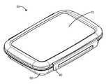
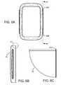
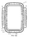
- FIG. 1Ais an isometric view of an exemplary embodiment of a vessel and lid in an attached configuration to provide an air-tight seal.
- FIG. 1Bis a side view of the vessel-lid combination of FIG. 1A .
- FIG. 1Cis a front view of the vessel-lid combination of FIG. 1A .
- FIG. 1Dis an exploded view of the vessel and lid.
- FIG. 2Ais an isometric view of the exemplary lid of the combination of FIG. 1A , with the latches in a latch position.
- FIG. 2Bis a front view of the lid of FIG. 2A .
- FIG. 2Cis a top view of the lid of FIG. 2A .
- FIG. 2Dis a bottom view of the lid of FIG. 2A .
- FIG. 3Ais a top view of an embodiment of a first mold shot structure for an exemplary embodiment of a lid for the combination of FIG. 1A .
- FIG. 3Bis a cross-sectional view taken along line 3 B- 3 B of FIG. 3A .
- FIG. 3Cis an enlarged portion of FIG. 3B , within circle 3 C of FIG. 3B .
- FIG. 3Dis a cross-sectional view taken along line 3 D- 3 D of FIG. 3A .
- FIG. 3Eis an enlarged portion of FIG. 3D , within circle 3 E of FIG. 3D .
- FIG. 4Ais a top view of an embodiment of a first mold shot structure for an exemplary embodiment of a lid, positioned in place on a vessel.
- FIG. 4Bis a cross-sectional view taken along line 4 B- 4 B of FIG. 4A .
- FIG. 4Cis an enlarged portion of FIG. 4B , within circle 4 C of FIG. 4B .
- FIG. 4Dis an isometric view of a portion of the first mold shot structure.
- FIG. 5Ais a top view of an embodiment of the lid of FIG. 1A .
- FIG. 5Bis a cross-sectional illustration of the lid of FIG. 5A , taken along line 5 B- 5 B of FIG. 5A .
- FIG. 5Cis an enlarged portion of FIG. 5B , within circle 5 C of FIG. 5B .
- FIG. 5Dis an enlarged portion of FIG. 5B , within circle 5 D of FIG. 5B .
- FIG. 5Eis an enlarged portion of FIG. 5B , within circle 5 E of FIG. 5B .
- FIG. 5Fis a cross-section view taken along line 5 F- 5 F of FIG. 5A , as latched onto a vessel as in FIG. 1A .
- FIG. 6Ais another top view of the lid of FIG. 1A .
- FIG. 6Bis a cutaway view, taken along line 6 B- 6 B of FIG. 6A .
- FIG. 6Cis an enlarged view of the portion of FIG. 6B within circuit 6 C.
- FIG. 7Ais a top view of an exemplary embodiment of a vessel-lid combination as in FIG. 1A , but with the latches in an opened position.
- FIG. 7Bis a cutaway view, taken along line 7 B- 7 B of FIG. 7A .
- FIG. 7Cis an enlarged view of the portion of FIG. 7B within circle 7 C.
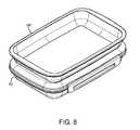
- FIG. 8is an isometric view showing an exemplary embodiment of a vessel-lid combination as in FIG. 1A , with another like vessel in a stacked configuration.
- FIG. 8Ais a top view of the stacked configuration of FIG. 8 .
- FIG. 8Bis a cutaway view taken along line 8 B- 8 B of FIG. 8A .
- FIG. 8Cis an enlarged view of the portion of FIG. 8C within circle 8 C.
- FIG. 9Ais a top view of an alternate embodiment of a lid.
- FIG. 9Bis a cross-sectional view of the lid of FIG. 9A , taken along line 9 B- 9 B of FIG. 9A .
- FIG. 9Cis an enlarged view of the portion of FIG. 9B within circle 9 C.
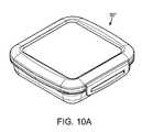
- FIGS. 10A and 10Bare respective isometric views of alternate embodiments of a vessel-lid combination.
- FIGS. 11A , 11 B and 11 Care respective isometric, bottom and end views of another exemplary embodiment of a vessel-lid combination.
- FIG. 12Ais a top view of the lid of the combination of FIG. 11A , with the latches in an open position.
- FIGS. 12B and 12Care respective bottom views of a lid as in FIG. 11A , without the seal (a first shot structure) and with the seal after a second molding shot.
- FIG. 13Ais a top view of a lid as in the vessel-lid combination of FIG. 11A .
- FIGS. 13B , 13 C, 13 D, 13 E and 13 Fare respective cross-sections taken along cross-sectional lines indicated in FIG. 13A .
- FIG. 13Gis an enlarged fragmentary view of the portion of FIG. 13F within circle 13 G.
- An exemplary embodiment of a vessel-lid combinationincludes a glass, ceramic or metal vessel having an open top surrounded by a peripheral edge, a lid fabricated of a plastic material, and a seal structure integrated with the lid to form a unitary structure.
- the lidis configured to attach to the open top by means of a latch or set of latches integrated with the lid, and the seal structure is configured to provide an air-tight seal between the lid and the peripheral edge of the vessel when the lid is attached to the vessel.
- the vesselis a container fabricated of a glass suitable for baking or oven heating applications. In a general sense the vessel could be any container with a suitable locking lip to engage the lid latches, including plastic, ceramic or other containers.
- FIGS. 1-8Cillustrate an exemplary embodiment of a vessel and lid system 50 , which includes a vessel 60 and a lid 70 with an integral seal structure and latches 80 .
- the vessel 60in one embodiment is a glass bakeware container, suitable for heating or baking food items in a hot oven.
- the vessel 60is made from a material which can withstand oven temperatures and cooling stresses, such as, by way of example only, borosilicate glass, which provides advantageous thermal properties for safe use under baking and cooling conditions.
- Other types of glass, metal or ceramic vesselscan be configured for use with the lid 70 , such that the vessels are formed with a sealing edge and latch engagement lip, as described more fully below.
- the cutaway view of FIG. 7Billustrates the construction of the exemplary vessel 60 in further detail.
- the vessel 60is a unitary structure, having an open top region 60 A, defined by a bottom portion 62 A, a sidewall portion 62 B and a peripheral rim portion 64 .
- a sealing edge portion 62 Cis defined by the sidewall portion at or adjacent the open top region.
- the sidewall portion 60 Bis angled outwardly from the bottom region, defining a 15 angle relative to the bottom portion. This particular angular arrangement is but one example, other configurations of the sidewall and bottom portions of the vessel may alternately be employed.
- the rim portion 64includes a generally flat top edge portion 64 A and a latch engagement lip portion 64 B.
- the lid 70is attached to the vessel 60 and latched in place to cover the open vessel top, using latches 80 connected by living hinges to the lid proper on opposite sides of the lid.
- the latcheshave latch hook features 82 A which engage the latch engagement lip portion 64 B of the vessel when the lid is placed on the vessel and the latches rotated about the hinges to the latched position shown in FIGS. 1A-1C , for example.
- a seal portion 90 Dengages a seal surface on the vessel as the lid is latched in place.
- the lid 70 in an exemplary embodimentis fabricated by injection molding using a two shot molding technique, in which a first shot structure is fabricated of a first plastic material, and then the lid structure is completed in a second shot in which a second plastic material is overmolded to a portion of the first shot structure.
- the primary, first shot lid structureis formed from a clear polymer such as polypropylene or similar structurally rigid polymer material.
- An exemplary over-mold material used in the second shotis a thermoplastic elastomer (TPE) material.
- FIGS. 2A-2Dillustrate the lid 70 in a completed form, i.e. after the overmolding process is completed to form the second plastic material to the first shot structure.
- FIGS. 3A-3E and 4 A- 4 Dillustrate an exemplary first shot structure 70 - 1 for the lid 70 .
- the first shot structure 70 - 1defines a web portion 70 - 1 A which is generally flat and is configured to extend over the open top region of the vessel when the lid is attached.
- the first shot structure 70 - 1includes a peripheral region 70 - 1 B extending around the periphery of the lid, and opposed end regions 70 - 1 C at the longitudinal ends of the lid, adjacent the sides of the lid which do not support latches 80 .
- Slot openings or channels 70 - 1 Dare formed in the first shot structure 70 - 1 at spaced locations around the peripheral region 70 - 1 B and in the end portions 70 - 1 C.
- slots 70 - 1 Dthere are eight slots 70 - 1 D in the first shot structure, and this number can be increased or decreased, depending on the configuration and size of the first shot structure.
- the slots 70 - 1 Dpass through the first shot structure from the top surface to the bottom surface of the peripheral region of the first shot structure.
- the structure 70 - 1further includes a downwardly protruding outer peripheral sidewall portion 70 - 1 E, and an inner peripheral rib portion 70 - 1 F defining a lower bonding ring portion 70 - 1 F 1 .
- Transverse rib portions 70 - 1 Gare formed between the inner rib portion and the outer sidewall portion at spaced intervals around the periphery of the first shot structure.
- the over-mold material applied to the first shot structure 70 - 1 in an exemplary embodimentis a thermoplastic elastomer material.
- this materialis molded in an injection molding process similar to that of the formation of the first shot structure 70 - 1 , except that the first shot structure is already in the mold cavity and thereby the second shot material attaches to the first shot structure as the hot second shot material enters into the mold and onto the first shot structure.
- the second shot materialis located preferentially based of the design of the mold to fill the desired locations. The two shot process in a general sense is widely used.
- the second shot materialis selected to provide good adhesion to the material of the first shot structure 70 - 1 .
- the second shot materialin an exemplary embodiment, may also be selected to provide appropriate bending characteristics, and a high coefficient of friction with the vessel material to ensure a high quality seal.
- the second shot materialmay also be selected to have good tear strength so as to retain good sealing over time.
- the first shot structuremay be polypropylene or similar structurally rigid polymer material
- the over-mold material used in the second shotis a thermoplastic elastomer (TPE) material.
- the second shot materialcovers at least the peripheral top edge portion 70 - 1 B of the first shot structure, and flows through flow channels to the peripheral underside of the first shot structure.
- a first portion of each flow channelis formed by the slots or channels 70 - 1 D formed in the first shot structure 70 - 1 .
- the flow channelsprovide a path for the second shot material to flow through the top surface of the lid, down the height of the vertical rib 70 - 1 F to reach the sealing area 70 - 1 I, where the second shot material defines a peripheral flexible seal portion.
- the flow channelsinclude vertical path portions 70 - 1 H below each slot 70 - 1 D, which are recessed into the rib portion 701 -F.
- the first partis the opening or through holes 70 - 1 D in the lid top.
- the second partis the vertical flow path portions 70 - 1 H defined by the recesses in the inner rib 70 - 1 F.
- the third portion of the flow pathis provided by the bonding ring portion 70 - 1 F 1 of the inner rib portion.
- the bonding ring portion 70 - 1 F 1provides additional adhesion surface area all around the sealing area 70 - 11 , where the second shot material will experience stress from repeated opening and closing of lid.
- the ribs 70 - 1 Gare formed at multiple locations around the periphery of the lid providing rigidity to the lid and a stop for the application of the lid to the vessel.
- the cross-section of the ribshows how the rib provides a stop surface 70 - 1 G 1 for the consumer to know when the lid is in place and when it is appropriate to engage the latch with the vessel.
- FIGS. 5A-7CAn exemplary embodiment of the lid 70 after completion of the second shot is illustrated in FIGS. 5A-7C .
- the stippled areasdesignate second shot material.
- the second shot materialproduces layers or features generally indicated by reference “ 90 _”, including the top peripheral layer 90 A, a layer 90 B on each vertical flow channel portion 70 - 1 H, a layer 90 C formed on the bonding ring portion 70 - 1 F 1 , which extends around the bottom edge of the bonding ring portion to form the peripheral seal portion 90 D. It is the circumferential seal portion 90 D, extending about the entire periphery of the bonding ring portion, that engages the sealing surface 62 C of the vessel 60 to create an air-tight seal.
- the seal portion 90 Dforms a flexible flap which bends as the lid is placed in position on the vessel, and is bent upwardly as the lid is latched, as shown, for example, in FIGS. 5F , 8 B and 8 C.
- the second shot materialincludes layers 90 E and 90 F formed on the latches 80 .
- the lid web surface portion 70 - 1 A in this exemplary embodimentis substantially flat or planar to receive a like vessel or any other item that would require stacking.
- the peripheral portion 70 - 1 Bis generally raised with respect to the web surface portion, and portion 70 - 1 B and end portions 70 - 1 C are covered with the second shot or over-mold material layer 90 A.
- the over-mold layer 90 A covering the raised peripheral portion 70 - 1 Bprovides a peripheral retention surface 90 A- 1 .
- the over-mold layer 90 Ais preferentially made of a material (such as TPE) with a high coefficient of friction with glass and other materials to aid in the retention of the stacking items.
- the retention surface 90 A- 1is designed to fit a like vessel appropriately snugly with sufficient manufacturing tolerance for a glass vessel manufacturing process.
- the stacking of a vessel on the lid of a vessel-lid systemis illustrated in FIGS. 8A-8C .
- the hinges 82are molded in a living hinge arrangement as part of the first shot structure 70 - 1 , and are fabricated of the same material as the first shot, e.g. polypropylene or similar structurally rigid polymer material.
- a living hingeis typically made from a polymer having long chains where the thinning out of the cross section allows for the chains to align parallel to the hinge allowing the chains to bend or hinge but due to the length of the chains reaching both thicker sections of plastic on both sides the chains connect the two sides.
- the chainsare very strong in tension.
- the second shot materiale.g. TPE, or over-mold does not cover the hinge 82 in this exemplary embodiment, but covers the first shot material on both sides of the hinge area.
- the ends 82 A, 82 B of the hinges 82are enclosed by a thickness of (TPE) or over-mold, e.g. as illustrated in FIGS. 6A-6C .
- TPEthickness of
- the living hinge endsact as a tear strip. Typically living hinges are subject to tearing off once a tear has been initiated at one of the ends.
- the highly elastic over-mold material at either end of the hingeacts to protect the hinge from tearing.
- the hinge endsact as another flow channel for the second shot or over-mold to flow from the main body of the lid onto the latch area. This can also be achieved by placing additional gates on each location where the second material is desired.
- the tooling and manufacturing processis much simplified allowing fewer simpler gates and far more process control.
- the hinge 82 ′is formed by the second shot, not the first.
- the latchis attached by the second shot. Through holes are provided in the latch body to allow for improved bonding with mechanical bond with both materials.
- FIGS. 9A-9Cillustrate this alternate embodiment of a hinge 80 ′ for the lid 70 ′ in which the latch 80 ′ is attached to the lid body proper by the second shot layer forming a living hinge 82 ′.
- FIG. 10Aa square vessel and lid configuration 50 ′′.
- FIG. 10Bshows another rectilinear vessel and lid configuration 50 ′′′.
- FIGS. 11A-13FA further embodiment 50 ′′′′ of a vessel and air-tight lid combination is illustrated in FIGS. 11A-13F .
- This exemplary embodimentincludes a vessel 60 and lid 170 .
- the exemplary vessel 60may be identical to the vessel described above regarding the exemplary embodiment of FIG. 1A , for example.
- the lid 170differs from the lid 70 of FIG. 1A in several respects.
- the lid 170has a peripheral downwardly extending skirt or outer peripheral edge, defining a lid perimeter which is slightly larger than the perimeter of the vessel, so that the skirt facilitates alignment of the lid onto the vessel.
- the lid skirtmay be provided with a lead-in chamfer or angle to further facilitate alignment of the lid onto the vessel.
- no second shot materialis molded onto the top surface of the lid, providing a cost reduction advantage relative to the embodiment of FIG. 1A .
- Relatively thick second shot flow leadersare formed on the underside of the lid peripheral region to facilitate each of injection of the molten material of the second shot. Stop ribs are formed in the underside of the lid peripheral region to define a correct latched position of the lid on the vessel, even thought the lid perimeter is larger than the vessel perimeter.
- FIGS. 11A-11Care respective isometric, bottom and end views of the vessel and air-tight lid combination 50 ′′′′ including the vessel 60 and with the lid 170 in a latched condition on the vessel.
- the constituent materials of the vessel and the lid, both the first shot material and the second shot material,may be identical to those of the embodiments of FIGS. 1-11 .
- FIG. 12Ais a top view of the lid 170 .
- no second shot materialis molded onto the top surfaces of the lid, visible in this top view.
- FIG. 12Bis a bottom view of the first shot structure 170 - 1 , with the latches 180 rotated about the living hinges to an unlatched configuration.
- the first shot structure 170 - 1includes a downwardly protruding outer peripheral sidewall portion 70 - 1 E, and an inner peripheral rib portion 170 - 1 F.
- Transverse rib portions 170 - 1 Gare formed between the inner rib portion and the outer sidewall portion at spaced intervals on the longitudinal sides of the first shot structure, three on each longitudinal side in this example.
- the rib portions 170 - 1 Gprovide attachment bosses for injection leader portions of the second shot material.
- the second shot structure 170 - 1also includes stop ribs 170 - 1 H at the transverse end portions of the second shot structure, in this example, two on each transverse end portion. These stop ribs have a depth sufficient to prevent the lid from being inserted too far into the vessel during an attachment.
- FIG. 12Cis a bottom view, showing the lid 170 in its completed form, after the second shot material has been overmolded onto the first shot structure.
- the second shot materialincludes a region overmolded onto the inner rib 170 - 1 F of the first shot structure, and defining the peripheral seal 190 D.
- the overmolded second shot materialis shown as the stippled regions in FIG. 12C . It is noted that, during the second shot molding process, the second shot material is injected at injection leader regions 190 F on the transverse rib or boss portions 170 - 1 G, and on narrow portions of the underside of the lid peripheral edge at the transverse end portions, as injection leaders 190 G.
- the bosses 170 - 1 Gprovide support for the second shot material, and provide crush force tending to compress the injection leader regions 190 F as the lid is latched onto the vessel.
- the peripheral seal 190 Dis dimensioned to provide appropriate seal force on the vessel and to accommodate the dimensional variations in the vessel due to manufacturing tolerances.
- the thickness of the sealmay be selected to provide an appropriate flexing as the lid is positioned on the vessel and latched.
- the sealmay have a width in a range of about 2.5 to 4 mm and a thickness at its thickest dimension on the order of 1 mm or so.
- the dimensions of the seal 190 D including its width and also its elevation positionmay vary spatially around the perimeter of the lid. This variation in dimensions can accommodate spatial variations in the vessel tolerance. For example, the tolerances in a rectangular vessel are typically greater in its corners, and the seal may be wider in the corners to accommodate wider dimensional variations. Also the elevation of the seal may vary, with the seal positioned lower in the corners relative to the vessel top edge.
- FIGS. 13A-13Gillustrate the features of the lid 170 and vessel-lid combination 50′′′′ in further detail.
- the lateral cross-sectional view of FIG. 13Btaken through line 13 B- 13 B of FIG. 13A , is taken through one of the ribs or bosses 170 - 1 G, and shows the second shot leader portion 190 B, with terminal portion 190 B- 1 at a crush region, being compressed between the edge of the vessel and the shoulder defined by the rib 170 - 1 G.
- FIG. 13Balso shows the second shot region 190 C formed on the outer side of the inner peripheral rib 170 - 1 F, around the rib tip and partially up the inner side of the rib, also forming the seal 190 D.
- FIG. 13Cis a lateral cross-section taken along line 13 C- 13 C of FIG. 13A through the combination 50 ′′′′, away from the ribs 170 - 1 G, and shows the tapered edge 170 - 1 E 1 of the outer peripheral rib of the lid 170 .
- FIG. 13Calso illustrates the oversize of the lid outer peripheral rib 170 - 1 E relative to the outer edge of the vessel 60 , with a small gap 188 between the rib and the vessel edge.
- FIG. 13Dis a longitudinal cross-sectional view taken along line 13 D- 13 D of FIG. 13A , through a second shot injection leader region 190 G at each lateral or end region of the lid 170 .
- the injection leader region 190 G, the second shot region 190 C and the seal 190 Dare shown in FIG. 13D .
- FIG. 13Eis a longitudinal cross-sectional view taken along line 13 E- 13 E of FIG. 13A , through the stop ribs 170 - 1 H at either end of the lid.
- FIG. 13Eshows the base of the stop ribs resting on the upper surface of the vessel edge, supporting the lid from further downward movement of the lid.
- FIG. 13Fis another longitudinal cross-sectional view, this one along line 13 F- 13 F of FIG. 13A , and offset from the stop ribs and the injection leader regions.
- FIG. 13Gis an enlarged view of a fragment of FIG. 13F within the phantom circle 13 G.
- the seal portion 190 D- 1 along the longitudinal side of the lidtransitions in elevation to seal portion 190 D- 2 approaching the lid corner, and to a lower elevation for corner seal portion 190 D- 3 .
- the inner peripheral rib 170 - 1 Falso transitions in elevation, to position the seal at the appropriate elevation.
Landscapes
- Engineering & Computer Science (AREA)
- Mechanical Engineering (AREA)
- Manufacturing & Machinery (AREA)
- Ceramic Engineering (AREA)
- Closures For Containers (AREA)
Abstract
Description
Claims (31)
Priority Applications (3)
| Application Number | Priority Date | Filing Date | Title |
|---|---|---|---|
| US13/193,456US8678230B2 (en) | 2010-07-30 | 2011-07-28 | Vessels with air-tight lid systems |
| PCT/US2011/046014WO2012016214A1 (en) | 2010-07-30 | 2011-07-29 | Vessels with air-tight lid systems |
| US14/223,637US9827730B2 (en) | 2010-07-30 | 2014-03-24 | Methods for fabricating lids for vessels |
Applications Claiming Priority (3)
| Application Number | Priority Date | Filing Date | Title |
|---|---|---|---|
| US36964410P | 2010-07-30 | 2010-07-30 | |
| US201161449563P | 2011-03-04 | 2011-03-04 | |
| US13/193,456US8678230B2 (en) | 2010-07-30 | 2011-07-28 | Vessels with air-tight lid systems |
Related Child Applications (1)
| Application Number | Title | Priority Date | Filing Date |
|---|---|---|---|
| US14/223,637DivisionUS9827730B2 (en) | 2010-07-30 | 2014-03-24 | Methods for fabricating lids for vessels |
Publications (2)
| Publication Number | Publication Date |
|---|---|
| US20120024855A1 US20120024855A1 (en) | 2012-02-02 |
| US8678230B2true US8678230B2 (en) | 2014-03-25 |
Family
ID=45525663
Family Applications (2)
| Application Number | Title | Priority Date | Filing Date |
|---|---|---|---|
| US13/193,456Active2032-04-29US8678230B2 (en) | 2010-07-30 | 2011-07-28 | Vessels with air-tight lid systems |
| US14/223,637Active - Reinstated2033-11-21US9827730B2 (en) | 2010-07-30 | 2014-03-24 | Methods for fabricating lids for vessels |
Family Applications After (1)
| Application Number | Title | Priority Date | Filing Date |
|---|---|---|---|
| US14/223,637Active - Reinstated2033-11-21US9827730B2 (en) | 2010-07-30 | 2014-03-24 | Methods for fabricating lids for vessels |
Country Status (2)
| Country | Link |
|---|---|
| US (2) | US8678230B2 (en) |
| WO (1) | WO2012016214A1 (en) |
Cited By (15)
| Publication number | Priority date | Publication date | Assignee | Title |
|---|---|---|---|---|
| USD742116S1 (en)* | 2014-07-29 | 2015-11-03 | Secure Medication Systems, Llc | Rectangular locking container |
| USD747606S1 (en)* | 2014-07-29 | 2016-01-19 | Secure Medication Systems, Llc | Locking container |
| US20170071402A1 (en)* | 2015-09-14 | 2017-03-16 | Herman Peng | Detachable microwave baking pan |
| USD787270S1 (en) | 2016-05-05 | 2017-05-23 | E. Mishan & Sons, Inc. | Microwavable mug |
| USD830765S1 (en) | 2016-03-04 | 2018-10-16 | Rubbermaid Incorporated | Lid for container |
| USD833211S1 (en) | 2016-03-04 | 2018-11-13 | Rubbermaid Incorporated | Lid for container |
| USD837588S1 (en) | 2016-03-04 | 2019-01-08 | Rubbermaid Incorporated | Lid for container |
| US10173826B2 (en) | 2015-05-15 | 2019-01-08 | Rubbermaid Incorporated | Ventable storage container and method of use |
| US10271684B1 (en) | 2015-07-30 | 2019-04-30 | Columbia Insurance Company | Adjustable lid for bakeware pan |
| USD906767S1 (en) | 2020-07-29 | 2021-01-05 | E. Mishan & Sons, Inc. | Food storage container |
| USD921444S1 (en)* | 2018-11-30 | 2021-06-08 | Sistema Plastics Limited | Container |
| USD921445S1 (en)* | 2018-11-30 | 2021-06-08 | Sistema Plastics Limited | Container |
| US20210284398A1 (en)* | 2020-03-16 | 2021-09-16 | Helen Of Troy Limited | Container with venting or multiple sealing feature |
| US11312562B2 (en)* | 2019-03-29 | 2022-04-26 | Free-Free Industrial Corp | Heat insulating container |
| US11325756B2 (en)* | 2018-03-09 | 2022-05-10 | M&M Industries, Inc. | Child resistant pail |
Families Citing this family (18)
| Publication number | Priority date | Publication date | Assignee | Title |
|---|---|---|---|---|
| CN202508434U (en)* | 2012-02-06 | 2012-10-31 | 山东业盛玻璃有限公司 | Silica gel glass cover and packaging container |
| CA2877972C (en) | 2012-07-03 | 2019-04-23 | Biogen Idec Ma Inc. | Device container |
| USD730699S1 (en)* | 2012-11-19 | 2015-06-02 | Fmc Manufacturing Company Limited | Container |
| USD741703S1 (en)* | 2014-01-08 | 2015-10-27 | Biogen Ma Inc. | Package |
| US9322588B2 (en)* | 2014-01-29 | 2016-04-26 | Fit & Fresh, Inc. | Hot or cold dual insulating food service assembly |
| US9962893B2 (en)* | 2014-05-02 | 2018-05-08 | Preddis, Llc | Combination cap and work support system |
| US9736590B2 (en)* | 2014-06-06 | 2017-08-15 | Infineon Technologies Ag | System and method for a microphone |
| KR102447144B1 (en)* | 2015-01-09 | 2022-09-26 | 삼성전자주식회사 | Methods of manufacturing photomasks, methods of forming photoresist patterns and methods of manufacturing semiconductor devices |
| US10392165B2 (en)* | 2015-02-25 | 2019-08-27 | Ideastream Consumer Products, Llc | Method for sealing materials |
| USD779973S1 (en)* | 2015-06-26 | 2017-02-28 | Sel Kee Na | Food package |
| US9988204B1 (en)* | 2017-03-02 | 2018-06-05 | Liya Levneff | Stackable pizza container |
| USD817023S1 (en)* | 2017-04-14 | 2018-05-08 | Steven Lamar Oliver | Soap container |
| USD948967S1 (en)* | 2017-12-07 | 2022-04-19 | The Decor Corporation Pty Ltd | Container base |
| WO2020137957A1 (en) | 2018-12-28 | 2020-07-02 | キョーラク株式会社 | Container and structure |
| US11840393B2 (en)* | 2020-01-29 | 2023-12-12 | Igloo Products Corp. | Cooler latch |
| USD1001597S1 (en)* | 2021-08-20 | 2023-10-17 | Sistema Plastics Limited | Lidded container |
| USD1020371S1 (en)* | 2021-08-20 | 2024-04-02 | Sistema Plastics Limited | Lidded container |
| USD1038749S1 (en)* | 2022-04-14 | 2024-08-13 | Bella Art de Nicole LLC | Bead retention tray |
Citations (101)
| Publication number | Priority date | Publication date | Assignee | Title |
|---|---|---|---|---|
| US1542115A (en) | 1924-10-25 | 1925-06-16 | Adolph O Weis | Food-storing dishes |
| US2928567A (en) | 1957-12-10 | 1960-03-15 | Joseph Davis Plastics Co | Utensil |
| US3117692A (en) | 1962-01-08 | 1964-01-14 | Lockheed Aircraft Corp | Container and lid assembly |
| US3409123A (en) | 1966-11-18 | 1968-11-05 | Dow Chemical Co | Interlocking container and lid |
| US3797694A (en) | 1970-09-02 | 1974-03-19 | Alfred B | Ventable sealed container |
| US3800972A (en) | 1971-11-23 | 1974-04-02 | Us Army | Trapped atmosphere closure assembly |
| US3817419A (en) | 1972-02-22 | 1974-06-18 | Continental Can Co | Latch to secure a closure on a container |
| US3861433A (en) | 1973-09-17 | 1975-01-21 | Plastofilm Ind Inc | Air tight food container |
| US4206845A (en) | 1977-09-06 | 1980-06-10 | Dart Industries Inc. | Food container |
| US4482077A (en) | 1982-11-23 | 1984-11-13 | Henderson Henning M | Perforated cover assembly |
| US4494674A (en) | 1984-01-30 | 1985-01-22 | Roof G Wayne | Resealable closure and container structure |
| US4501378A (en) | 1982-12-14 | 1985-02-26 | Shop-Vac Corporation | Resilient detented lid latch |
| US4512498A (en) | 1983-10-21 | 1985-04-23 | Karl Liebinger Medizintechnik Gmbh & Co. | Sterilizable container |
| US4562047A (en) | 1983-12-19 | 1985-12-31 | American Sterilizer Company | Indicator seal and sterilizer container |
| US4702389A (en) | 1980-10-14 | 1987-10-27 | Kraft, Inc. | Rigid lid system |
| US4703857A (en) | 1986-01-20 | 1987-11-03 | Bellaplast Gmbh | Thin-walled stackable container lid |
| US4795056A (en) | 1988-03-31 | 1989-01-03 | Gerber Products Company | Microwave dish cover |
| US4936483A (en) | 1988-01-20 | 1990-06-26 | Tecnoma | Receptacle which can be dismantled and which can withstand an internal pressure |
| US4951832A (en) | 1989-10-02 | 1990-08-28 | Tenney Brian J | Multi-functional space saving container system |
| US4971774A (en) | 1987-04-03 | 1990-11-20 | Aesculap Ag | Sterilizing container for surgical instruments |
| US5016756A (en) | 1989-06-01 | 1991-05-21 | Aladdin Synergetics, Inc. | Multi-partition food storage and multiple serving apparatus |
| US5116240A (en) | 1989-06-01 | 1992-05-26 | Aladdin Synergetics, Inc. | Multi-partition food storage and multiple serving apparatus |
| US5115934A (en) | 1990-11-28 | 1992-05-26 | Highland Plastics, Inc. | Tamper resistant container lid |
| US5184745A (en) | 1990-12-31 | 1993-02-09 | Petrina L. Havens | Storage container set |
| US5356026A (en) | 1993-03-22 | 1994-10-18 | Plastics, Inc. | Double seal container |
| US5409128A (en) | 1994-04-06 | 1995-04-25 | Safeco Plastics, Inc. | Stackable container |
| US5586656A (en) | 1995-01-13 | 1996-12-24 | Abrums; Rolin L. | Nestable and stackable storage unit |
| US5641065A (en) | 1995-06-22 | 1997-06-24 | Paragon Group Of Plastics Companies, Inc. | Medical instrument soaking, transporting and storage container |
| US5692617A (en) | 1996-01-11 | 1997-12-02 | Adams; Kathleen | Container storage system |
| US5699925A (en) | 1996-05-14 | 1997-12-23 | Petruzzi; Thomas G. | Interlocking stackable container storage system |
| US5799792A (en) | 1995-01-13 | 1998-09-01 | Abrums; Rolin L. | Nestable and stackable storage unit |
| US5944211A (en) | 1997-08-26 | 1999-08-31 | Anchor Hocking Plastics/Plastics Inc. | Container system including an air evacuation valve |
| US6129234A (en) | 1996-03-22 | 2000-10-10 | Branko Culig | Plate-shaped cover for cooking vessels or the like |
| US6170691B1 (en) | 1997-10-02 | 2001-01-09 | M & M Industries, Inc. | Open-head container and lid assembly |
| CA2314537A1 (en) | 2000-07-25 | 2002-01-25 | Unknown | Airtight and liquid tight container |
| US6343708B1 (en) | 1999-06-07 | 2002-02-05 | John Riso | Storage assembly for accessing small tools and components |
| US20020104846A1 (en) | 2001-02-02 | 2002-08-08 | Richard Rosenfeld | Porcelain container with plastic lid |
| US20030019878A1 (en) | 2001-07-25 | 2003-01-30 | Dionisio Scarabelli | Hermetic container for frozen food preservation and microwave oven thawing |
| US20030116572A1 (en) | 2001-12-20 | 2003-06-26 | World Kitchen, Inc. | Sealing cover for a container |
| US6648168B2 (en)* | 2000-08-30 | 2003-11-18 | Nippon Sanso Corporation | Insulated container |
| US6729472B2 (en) | 2001-01-12 | 2004-05-04 | Wki Holding Company, Inc. | Container assembly and nesting set thereof |
| USD493335S1 (en) | 2003-09-15 | 2004-07-27 | Vincenzo International | Container |
| US20040155048A1 (en)* | 2003-02-04 | 2004-08-12 | Rehrig Pacific Company | Container with lid |
| US6793096B1 (en) | 2003-04-08 | 2004-09-21 | Hana Cobi Co., Ltd. | Food item receiving container |
| US6796430B2 (en) | 2002-02-15 | 2004-09-28 | Doug Mercier | Nesting containers and lids |
| USD499931S1 (en) | 2003-10-17 | 2004-12-21 | Hana Cobi Co., Ltd | Lid for an airtight container for storing foods |
| USD500227S1 (en) | 2003-05-12 | 2004-12-28 | Hana Cobi Co., Ltd. | Lid for an airtight container for storing foods |
| US20050006390A1 (en) | 2003-07-09 | 2005-01-13 | Wang Soo Chang | Container with double lids |
| USD501764S1 (en) | 2003-09-29 | 2005-02-15 | William S. Lerner | Square food storage container with removable thermal preservation insert |
| US20050045628A1 (en) | 2003-09-02 | 2005-03-03 | Chan Li Chun | Cosmetic container |
| DE20320088U1 (en) | 2003-12-23 | 2005-05-12 | Emsa Werke Wulf Gmbh & Co Kg | Lid for a storage box |
| US20050139604A1 (en) | 2003-12-30 | 2005-06-30 | Kim Chang-Ho | Non-plastic container for storing food |
| US20060027588A1 (en) | 2004-08-04 | 2006-02-09 | Miriam Mackovic-Basic | Removable clip for beverage lid |
| USD516376S1 (en) | 2004-04-28 | 2006-03-07 | Hana Cobi Co., Ltd. | Lid for container for storing foods |
| US20060070907A1 (en) | 2004-10-06 | 2006-04-06 | O'shea Timothy P | Nesting containers with male to female lid to container attachment |
| US7090089B2 (en) | 2001-01-25 | 2006-08-15 | Snapware Corporation | Container and sealing cover |
| US7097067B2 (en) | 2001-07-25 | 2006-08-29 | Dionisio Scarabelli | Hermetically sealable container with internal partial vacuum making facilities |
| US7097066B2 (en) | 2002-01-29 | 2006-08-29 | The Glad Products Company | Plate container with detachable cover |
| USD528357S1 (en) | 2004-05-17 | 2006-09-19 | L&F Plastics Co., Ltd. | Cover for container |
| US20060207993A1 (en) | 2005-03-21 | 2006-09-21 | Copeland Bruce W | Cereal bowl |
| US20060261065A1 (en) | 2005-05-17 | 2006-11-23 | Rubbermaid Incorporated | Reversible lid storage container |
| USD536571S1 (en) | 2005-04-20 | 2007-02-13 | Hana Cobi Co., Ltd. | Lid for container for storing foods |
| US20070119743A1 (en) | 2005-02-23 | 2007-05-31 | The Glad Products Company | Container |
| WO2007064833A2 (en) | 2005-12-01 | 2007-06-07 | Foldware, Inc. | Nestable containers with bending covers for improved storage |
| US20070170190A1 (en) | 2005-10-11 | 2007-07-26 | Frederic Milesi | Pinching seal for airtight containers |
| US20070187277A1 (en) | 2006-02-09 | 2007-08-16 | Rubbermaid Incorporated | Storage container and container system |
| US7261219B2 (en) | 1997-03-18 | 2007-08-28 | The Glad Products Company | Sealing container |
| USD549519S1 (en) | 2004-11-18 | 2007-08-28 | Jaegu Moon | Container lid |
| USD556517S1 (en) | 2006-02-17 | 2007-12-04 | Snapware Corporation | Combined airtight lid and container |
| US20070284276A1 (en) | 2006-06-09 | 2007-12-13 | Nicolaas Luttik | Container assembly having stacking means |
| US20080000795A1 (en) | 2006-06-29 | 2008-01-03 | Lynda Deakin | Stackable containers |
| USD562083S1 (en) | 2006-02-17 | 2008-02-19 | Snapware Corporation | Combined airtight lid and container |
| US20080105684A1 (en) | 2004-12-14 | 2008-05-08 | Brendan John Lindsay | Latchable Lid Assemblies |
| US20080110911A1 (en) | 2006-10-30 | 2008-05-15 | Hsin-Yu Chen | Fastening structure and seal box with the fastening structure |
| USD580218S1 (en) | 2007-11-23 | 2008-11-11 | Lock & Lock Co., Ltd. | Food storage container lid |
| US20090000977A1 (en) | 2006-01-18 | 2009-01-01 | Coonce Ryan J | System of Releasably Interlocking Container Covers |
| US20090008284A1 (en) | 2006-02-16 | 2009-01-08 | Snapware Corporation | Container/Lid Combination For Storing Food and other Articles |
| US20090026205A1 (en) | 2007-07-26 | 2009-01-29 | Myoung Moon L.C Co., Ltd. | Receptacle with lid integrally formed with packing having wing section |
| US20090057318A1 (en) | 2007-03-09 | 2009-03-05 | Danielle Aseff | Food cooking, serving and storage device |
| US20090078715A1 (en) | 2007-09-21 | 2009-03-26 | Daewoo Tech, Co., Ltd | Lid for airtight container |
| US7510096B2 (en) | 2003-04-09 | 2009-03-31 | Korea Alphaline Co., Ltd. | Multi-layered container with intermediate lid |
| US20090084796A1 (en) | 2006-01-18 | 2009-04-02 | Coonce Ryan J | Containers with interlocking covers |
| USD590666S1 (en) | 2007-10-05 | 2009-04-21 | Korea Alphaline Co., Ltd. | Food storage container |
| USD591112S1 (en) | 2007-09-21 | 2009-04-28 | Korea Alphaline Co., Ltd. | Food storage container |
| US20090166369A1 (en) | 2006-06-01 | 2009-07-02 | Savicki Alan F | Container having an articulated cover |
| US20090173656A1 (en) | 2006-02-09 | 2009-07-09 | Rubbermaid Incorporated | Storage Container and Container System |
| US20090206080A1 (en) | 2008-02-07 | 2009-08-20 | Ribi Hans O | Universal Lids and Methods for Making and Using the Same |
| US20090218360A1 (en)* | 2008-02-29 | 2009-09-03 | Suk Jong Cheul | Lid for Airtight Containers |
| US20090223986A1 (en) | 2008-02-10 | 2009-09-10 | Xubin Song | Preservation container cover |
| US7594586B2 (en) | 2006-08-05 | 2009-09-29 | Cai Edward Z | Vacuum generating device for sealing perishable products and method of use |
| USD601384S1 (en) | 2008-04-03 | 2009-10-06 | M/S. Tokyo Plast International Ltd. | Covered dish |
| USD604119S1 (en) | 2008-04-11 | 2009-11-17 | Lock & Lock Co., Ltd. | Airtight container for food storage |
| US7621417B2 (en) | 2004-10-13 | 2009-11-24 | Rubbermaid Incorporated | Container with integral foam gasket |
| US20100065461A1 (en) | 2008-09-18 | 2010-03-18 | Khim Seang Chhay | Stackable container with interlocking arrangement |
| US7726483B2 (en) | 2005-02-23 | 2010-06-01 | The Glad Products Company | Stacked containers |
| US20100170204A1 (en) | 2008-07-03 | 2010-07-08 | Anchor Hocking, Llc | Container lids and methods of sealing containers |
| US20100176022A1 (en) | 2009-01-09 | 2010-07-15 | Rubbermaid Incorporated | Food storage container and container system |
| US20100200588A1 (en) | 2006-03-14 | 2010-08-12 | The Glad Products Company | Vacuum storage container |
| US20100237070A1 (en) | 2007-11-28 | 2010-09-23 | Coonce Ryan J | Storage container |
| DE202010007217U1 (en) | 2010-05-25 | 2010-09-30 | Emsa Gmbh | Lid for a storage box |
| US20110163099A1 (en) | 2008-05-21 | 2011-07-07 | Dipietro Dean | Container with Sealing Lid |
Family Cites Families (14)
| Publication number | Priority date | Publication date | Assignee | Title |
|---|---|---|---|---|
| US3688942A (en)* | 1970-11-20 | 1972-09-05 | Continental Can Co | Container and closure combination |
| US3982875A (en)* | 1974-09-30 | 1976-09-28 | Bud Antle, Inc. | Apparatus for making molded articles of expanded cellular material and product thereof |
| US4123495A (en)* | 1976-01-12 | 1978-10-31 | Bud Antle, Inc. | Method for making molded articles of expanded cellular material |
| JPS63221568A (en)* | 1987-03-10 | 1988-09-14 | 矢崎総業株式会社 | Connector housing and its manufacturing method |
| US5674456A (en)* | 1992-09-15 | 1997-10-07 | Quintus Chess | Medical specimen shipping container |
| GB2277735A (en)* | 1993-05-07 | 1994-11-09 | Robinson & Sons Ltd | Two material injection moulding of sealing closure |
| JPH08207079A (en)* | 1995-02-02 | 1996-08-13 | Yamashita Denki Kk | Method for forming different materials for airtight containers |
| US20020020416A1 (en)* | 2000-08-11 | 2002-02-21 | David Namey | Two-shot injection molded nasal/oral mask |
| US7210917B2 (en)* | 2003-12-30 | 2007-05-01 | Mold-Masters Limited | Two position double injection molding apparatus |
| WO2010150985A2 (en)* | 2009-06-26 | 2010-12-29 | 주식회사 코멕스산업 | Airtight vessel and manufacturing method thereof |
| US9475619B2 (en)* | 2010-06-03 | 2016-10-25 | Andrew John Procter | Beverage container sealing lid |
| US8870021B2 (en)* | 2010-07-30 | 2014-10-28 | Snapware Corporation | Air-tight ceramic or glass vessels and lid systems |
| US8448798B2 (en)* | 2010-10-05 | 2013-05-28 | Weatherchem Corporation | Dispensing closure with pliable sealing surface |
| US8534492B2 (en)* | 2011-04-01 | 2013-09-17 | Wki Holding Company, Inc. | Container with air-tight lid |
- 2011
- 2011-07-28USUS13/193,456patent/US8678230B2/enactiveActive
- 2011-07-29WOPCT/US2011/046014patent/WO2012016214A1/enactiveApplication Filing
- 2014
- 2014-03-24USUS14/223,637patent/US9827730B2/enactiveActive - Reinstated
Patent Citations (105)
| Publication number | Priority date | Publication date | Assignee | Title |
|---|---|---|---|---|
| US1542115A (en) | 1924-10-25 | 1925-06-16 | Adolph O Weis | Food-storing dishes |
| US2928567A (en) | 1957-12-10 | 1960-03-15 | Joseph Davis Plastics Co | Utensil |
| US3117692A (en) | 1962-01-08 | 1964-01-14 | Lockheed Aircraft Corp | Container and lid assembly |
| US3409123A (en) | 1966-11-18 | 1968-11-05 | Dow Chemical Co | Interlocking container and lid |
| US3797694A (en) | 1970-09-02 | 1974-03-19 | Alfred B | Ventable sealed container |
| US3800972A (en) | 1971-11-23 | 1974-04-02 | Us Army | Trapped atmosphere closure assembly |
| US3817419A (en) | 1972-02-22 | 1974-06-18 | Continental Can Co | Latch to secure a closure on a container |
| US3861433A (en) | 1973-09-17 | 1975-01-21 | Plastofilm Ind Inc | Air tight food container |
| US4206845A (en) | 1977-09-06 | 1980-06-10 | Dart Industries Inc. | Food container |
| US4702389A (en) | 1980-10-14 | 1987-10-27 | Kraft, Inc. | Rigid lid system |
| US4482077A (en) | 1982-11-23 | 1984-11-13 | Henderson Henning M | Perforated cover assembly |
| US4501378A (en) | 1982-12-14 | 1985-02-26 | Shop-Vac Corporation | Resilient detented lid latch |
| US4512498A (en) | 1983-10-21 | 1985-04-23 | Karl Liebinger Medizintechnik Gmbh & Co. | Sterilizable container |
| US4562047A (en) | 1983-12-19 | 1985-12-31 | American Sterilizer Company | Indicator seal and sterilizer container |
| US4494674A (en) | 1984-01-30 | 1985-01-22 | Roof G Wayne | Resealable closure and container structure |
| US4703857A (en) | 1986-01-20 | 1987-11-03 | Bellaplast Gmbh | Thin-walled stackable container lid |
| US4971774A (en) | 1987-04-03 | 1990-11-20 | Aesculap Ag | Sterilizing container for surgical instruments |
| US4936483A (en) | 1988-01-20 | 1990-06-26 | Tecnoma | Receptacle which can be dismantled and which can withstand an internal pressure |
| US4795056A (en) | 1988-03-31 | 1989-01-03 | Gerber Products Company | Microwave dish cover |
| US5016756A (en) | 1989-06-01 | 1991-05-21 | Aladdin Synergetics, Inc. | Multi-partition food storage and multiple serving apparatus |
| US5116240A (en) | 1989-06-01 | 1992-05-26 | Aladdin Synergetics, Inc. | Multi-partition food storage and multiple serving apparatus |
| US4951832A (en) | 1989-10-02 | 1990-08-28 | Tenney Brian J | Multi-functional space saving container system |
| US5115934A (en) | 1990-11-28 | 1992-05-26 | Highland Plastics, Inc. | Tamper resistant container lid |
| US5184745A (en) | 1990-12-31 | 1993-02-09 | Petrina L. Havens | Storage container set |
| US5356026A (en) | 1993-03-22 | 1994-10-18 | Plastics, Inc. | Double seal container |
| US5769229A (en) | 1993-03-22 | 1998-06-23 | Plastics, Inc. | Container assemblies of different sizes which stack, nest and assemble separately and in combinaton |
| US5409128A (en) | 1994-04-06 | 1995-04-25 | Safeco Plastics, Inc. | Stackable container |
| US5586656A (en) | 1995-01-13 | 1996-12-24 | Abrums; Rolin L. | Nestable and stackable storage unit |
| US5799792A (en) | 1995-01-13 | 1998-09-01 | Abrums; Rolin L. | Nestable and stackable storage unit |
| US5641065A (en) | 1995-06-22 | 1997-06-24 | Paragon Group Of Plastics Companies, Inc. | Medical instrument soaking, transporting and storage container |
| US5692617A (en) | 1996-01-11 | 1997-12-02 | Adams; Kathleen | Container storage system |
| US6129234A (en) | 1996-03-22 | 2000-10-10 | Branko Culig | Plate-shaped cover for cooking vessels or the like |
| US5699925A (en) | 1996-05-14 | 1997-12-23 | Petruzzi; Thomas G. | Interlocking stackable container storage system |
| US7261219B2 (en) | 1997-03-18 | 2007-08-28 | The Glad Products Company | Sealing container |
| US5944211A (en) | 1997-08-26 | 1999-08-31 | Anchor Hocking Plastics/Plastics Inc. | Container system including an air evacuation valve |
| US6170691B1 (en) | 1997-10-02 | 2001-01-09 | M & M Industries, Inc. | Open-head container and lid assembly |
| US6343708B1 (en) | 1999-06-07 | 2002-02-05 | John Riso | Storage assembly for accessing small tools and components |
| CA2314537A1 (en) | 2000-07-25 | 2002-01-25 | Unknown | Airtight and liquid tight container |
| US6648168B2 (en)* | 2000-08-30 | 2003-11-18 | Nippon Sanso Corporation | Insulated container |
| US6729472B2 (en) | 2001-01-12 | 2004-05-04 | Wki Holding Company, Inc. | Container assembly and nesting set thereof |
| US7090089B2 (en) | 2001-01-25 | 2006-08-15 | Snapware Corporation | Container and sealing cover |
| US20020104846A1 (en) | 2001-02-02 | 2002-08-08 | Richard Rosenfeld | Porcelain container with plastic lid |
| US20030019878A1 (en) | 2001-07-25 | 2003-01-30 | Dionisio Scarabelli | Hermetic container for frozen food preservation and microwave oven thawing |
| US7097067B2 (en) | 2001-07-25 | 2006-08-29 | Dionisio Scarabelli | Hermetically sealable container with internal partial vacuum making facilities |
| US20030116572A1 (en) | 2001-12-20 | 2003-06-26 | World Kitchen, Inc. | Sealing cover for a container |
| US7097066B2 (en) | 2002-01-29 | 2006-08-29 | The Glad Products Company | Plate container with detachable cover |
| US6796430B2 (en) | 2002-02-15 | 2004-09-28 | Doug Mercier | Nesting containers and lids |
| US20040155048A1 (en)* | 2003-02-04 | 2004-08-12 | Rehrig Pacific Company | Container with lid |
| US6793096B1 (en) | 2003-04-08 | 2004-09-21 | Hana Cobi Co., Ltd. | Food item receiving container |
| US7510096B2 (en) | 2003-04-09 | 2009-03-31 | Korea Alphaline Co., Ltd. | Multi-layered container with intermediate lid |
| USD500227S1 (en) | 2003-05-12 | 2004-12-28 | Hana Cobi Co., Ltd. | Lid for an airtight container for storing foods |
| US20050006390A1 (en) | 2003-07-09 | 2005-01-13 | Wang Soo Chang | Container with double lids |
| US20050045628A1 (en) | 2003-09-02 | 2005-03-03 | Chan Li Chun | Cosmetic container |
| USD503872S1 (en) | 2003-09-15 | 2005-04-12 | Vincenzo International | Container |
| USD493335S1 (en) | 2003-09-15 | 2004-07-27 | Vincenzo International | Container |
| USD501764S1 (en) | 2003-09-29 | 2005-02-15 | William S. Lerner | Square food storage container with removable thermal preservation insert |
| USD499931S1 (en) | 2003-10-17 | 2004-12-21 | Hana Cobi Co., Ltd | Lid for an airtight container for storing foods |
| DE20320088U1 (en) | 2003-12-23 | 2005-05-12 | Emsa Werke Wulf Gmbh & Co Kg | Lid for a storage box |
| US20050139604A1 (en) | 2003-12-30 | 2005-06-30 | Kim Chang-Ho | Non-plastic container for storing food |
| EP1550617A1 (en)* | 2003-12-30 | 2005-07-06 | Hana Cobi Co., Ltd. | Non-plastic container for storing food |
| USD516376S1 (en) | 2004-04-28 | 2006-03-07 | Hana Cobi Co., Ltd. | Lid for container for storing foods |
| USD528357S1 (en) | 2004-05-17 | 2006-09-19 | L&F Plastics Co., Ltd. | Cover for container |
| US20060027588A1 (en) | 2004-08-04 | 2006-02-09 | Miriam Mackovic-Basic | Removable clip for beverage lid |
| US20060070907A1 (en) | 2004-10-06 | 2006-04-06 | O'shea Timothy P | Nesting containers with male to female lid to container attachment |
| US7621417B2 (en) | 2004-10-13 | 2009-11-24 | Rubbermaid Incorporated | Container with integral foam gasket |
| USD549519S1 (en) | 2004-11-18 | 2007-08-28 | Jaegu Moon | Container lid |
| US20080105684A1 (en) | 2004-12-14 | 2008-05-08 | Brendan John Lindsay | Latchable Lid Assemblies |
| US20070119743A1 (en) | 2005-02-23 | 2007-05-31 | The Glad Products Company | Container |
| US20100170824A1 (en) | 2005-02-23 | 2010-07-08 | The Glad Products Company | Container |
| US7726483B2 (en) | 2005-02-23 | 2010-06-01 | The Glad Products Company | Stacked containers |
| US20060207993A1 (en) | 2005-03-21 | 2006-09-21 | Copeland Bruce W | Cereal bowl |
| USD536571S1 (en) | 2005-04-20 | 2007-02-13 | Hana Cobi Co., Ltd. | Lid for container for storing foods |
| US20060261065A1 (en) | 2005-05-17 | 2006-11-23 | Rubbermaid Incorporated | Reversible lid storage container |
| US20070170190A1 (en) | 2005-10-11 | 2007-07-26 | Frederic Milesi | Pinching seal for airtight containers |
| WO2007064833A2 (en) | 2005-12-01 | 2007-06-07 | Foldware, Inc. | Nestable containers with bending covers for improved storage |
| US20090084796A1 (en) | 2006-01-18 | 2009-04-02 | Coonce Ryan J | Containers with interlocking covers |
| US20090000977A1 (en) | 2006-01-18 | 2009-01-01 | Coonce Ryan J | System of Releasably Interlocking Container Covers |
| US20090173656A1 (en) | 2006-02-09 | 2009-07-09 | Rubbermaid Incorporated | Storage Container and Container System |
| US20070187277A1 (en) | 2006-02-09 | 2007-08-16 | Rubbermaid Incorporated | Storage container and container system |
| US20090008284A1 (en) | 2006-02-16 | 2009-01-08 | Snapware Corporation | Container/Lid Combination For Storing Food and other Articles |
| USD562083S1 (en) | 2006-02-17 | 2008-02-19 | Snapware Corporation | Combined airtight lid and container |
| USD556517S1 (en) | 2006-02-17 | 2007-12-04 | Snapware Corporation | Combined airtight lid and container |
| US20100200588A1 (en) | 2006-03-14 | 2010-08-12 | The Glad Products Company | Vacuum storage container |
| US20090166369A1 (en) | 2006-06-01 | 2009-07-02 | Savicki Alan F | Container having an articulated cover |
| US20070284276A1 (en) | 2006-06-09 | 2007-12-13 | Nicolaas Luttik | Container assembly having stacking means |
| US20080000795A1 (en) | 2006-06-29 | 2008-01-03 | Lynda Deakin | Stackable containers |
| US7594586B2 (en) | 2006-08-05 | 2009-09-29 | Cai Edward Z | Vacuum generating device for sealing perishable products and method of use |
| US20080110911A1 (en) | 2006-10-30 | 2008-05-15 | Hsin-Yu Chen | Fastening structure and seal box with the fastening structure |
| US20090057318A1 (en) | 2007-03-09 | 2009-03-05 | Danielle Aseff | Food cooking, serving and storage device |
| US20090026205A1 (en) | 2007-07-26 | 2009-01-29 | Myoung Moon L.C Co., Ltd. | Receptacle with lid integrally formed with packing having wing section |
| US20090078715A1 (en) | 2007-09-21 | 2009-03-26 | Daewoo Tech, Co., Ltd | Lid for airtight container |
| USD591112S1 (en) | 2007-09-21 | 2009-04-28 | Korea Alphaline Co., Ltd. | Food storage container |
| USD590666S1 (en) | 2007-10-05 | 2009-04-21 | Korea Alphaline Co., Ltd. | Food storage container |
| USD580218S1 (en) | 2007-11-23 | 2008-11-11 | Lock & Lock Co., Ltd. | Food storage container lid |
| US20100237070A1 (en) | 2007-11-28 | 2010-09-23 | Coonce Ryan J | Storage container |
| US20090206080A1 (en) | 2008-02-07 | 2009-08-20 | Ribi Hans O | Universal Lids and Methods for Making and Using the Same |
| US20090223986A1 (en) | 2008-02-10 | 2009-09-10 | Xubin Song | Preservation container cover |
| US20090218360A1 (en)* | 2008-02-29 | 2009-09-03 | Suk Jong Cheul | Lid for Airtight Containers |
| USD601384S1 (en) | 2008-04-03 | 2009-10-06 | M/S. Tokyo Plast International Ltd. | Covered dish |
| USD604119S1 (en) | 2008-04-11 | 2009-11-17 | Lock & Lock Co., Ltd. | Airtight container for food storage |
| US20110163099A1 (en) | 2008-05-21 | 2011-07-07 | Dipietro Dean | Container with Sealing Lid |
| US20100170204A1 (en) | 2008-07-03 | 2010-07-08 | Anchor Hocking, Llc | Container lids and methods of sealing containers |
| US20100065461A1 (en) | 2008-09-18 | 2010-03-18 | Khim Seang Chhay | Stackable container with interlocking arrangement |
| US20100176022A1 (en) | 2009-01-09 | 2010-07-15 | Rubbermaid Incorporated | Food storage container and container system |
| DE202010007217U1 (en) | 2010-05-25 | 2010-09-30 | Emsa Gmbh | Lid for a storage box |
Non-Patent Citations (2)
| Title |
|---|
| International Search Report, PCT/US2011/04601, mailed Sep. 8, 2011. |
| Written Opinion of the International Searching Authority, PCT/US2011/046014, mailed Sep. 8, 2011. |
Cited By (21)
| Publication number | Priority date | Publication date | Assignee | Title |
|---|---|---|---|---|
| USD747606S1 (en)* | 2014-07-29 | 2016-01-19 | Secure Medication Systems, Llc | Locking container |
| USD747607S1 (en)* | 2014-07-29 | 2016-01-19 | Secure Medication Systems, Llc | Rectangular locking container |
| USD742116S1 (en)* | 2014-07-29 | 2015-11-03 | Secure Medication Systems, Llc | Rectangular locking container |
| US10173826B2 (en) | 2015-05-15 | 2019-01-08 | Rubbermaid Incorporated | Ventable storage container and method of use |
| US10271684B1 (en) | 2015-07-30 | 2019-04-30 | Columbia Insurance Company | Adjustable lid for bakeware pan |
| US20170071402A1 (en)* | 2015-09-14 | 2017-03-16 | Herman Peng | Detachable microwave baking pan |
| USD830765S1 (en) | 2016-03-04 | 2018-10-16 | Rubbermaid Incorporated | Lid for container |
| USD833211S1 (en) | 2016-03-04 | 2018-11-13 | Rubbermaid Incorporated | Lid for container |
| USD837588S1 (en) | 2016-03-04 | 2019-01-08 | Rubbermaid Incorporated | Lid for container |
| USD787270S1 (en) | 2016-05-05 | 2017-05-23 | E. Mishan & Sons, Inc. | Microwavable mug |
| US11554905B2 (en)* | 2018-03-09 | 2023-01-17 | M & M Industries, Inc. | Child resistant pail |
| US20220242628A1 (en)* | 2018-03-09 | 2022-08-04 | Glenn H. Morris, Jr. | Child Resistant Pail |
| US11325756B2 (en)* | 2018-03-09 | 2022-05-10 | M&M Industries, Inc. | Child resistant pail |
| USD921444S1 (en)* | 2018-11-30 | 2021-06-08 | Sistema Plastics Limited | Container |
| USD921445S1 (en)* | 2018-11-30 | 2021-06-08 | Sistema Plastics Limited | Container |
| US11312562B2 (en)* | 2019-03-29 | 2022-04-26 | Free-Free Industrial Corp | Heat insulating container |
| US20210284398A1 (en)* | 2020-03-16 | 2021-09-16 | Helen Of Troy Limited | Container with venting or multiple sealing feature |
| US11639252B2 (en)* | 2020-03-16 | 2023-05-02 | Helen Of Troy Limited | Container with venting or multiple sealing feature |
| USD912478S1 (en) | 2020-07-29 | 2021-03-09 | E. Mishan & Sons, Inc. | Food storage container |
| USD912479S1 (en) | 2020-07-29 | 2021-03-09 | E. Mishan & Sons, Inc. | Food storage container |
| USD906767S1 (en) | 2020-07-29 | 2021-01-05 | E. Mishan & Sons, Inc. | Food storage container |
Also Published As
| Publication number | Publication date |
|---|---|
| US9827730B2 (en) | 2017-11-28 |
| US20120024855A1 (en) | 2012-02-02 |
| US20140284840A1 (en) | 2014-09-25 |
| WO2012016214A1 (en) | 2012-02-02 |
Similar Documents
| Publication | Publication Date | Title |
|---|---|---|
| US8678230B2 (en) | Vessels with air-tight lid systems | |
| US9643757B2 (en) | Method of merchandising lids and vessels | |
| US8870021B2 (en) | Air-tight ceramic or glass vessels and lid systems | |
| EP2197759B1 (en) | Tamper resistant container with locking rim | |
| US20120248116A1 (en) | Container with air-tight lid | |
| US20100096398A1 (en) | Pour and seal assembly and method of using the same | |
| KR102044036B1 (en) | A stackable lids close sealed staffed | |
| CN104487358A (en) | Airtight container lid assembly | |
| KR102604466B1 (en) | storage box | |
| JP6178133B2 (en) | Lid, container provided with the same, and method of manufacturing lid | |
| KR200441597Y1 (en) | Airtight containers for food storage | |
| KR200469248Y1 (en) | Lunch package with meal plate | |
| JP7054175B2 (en) | Inner fitting container for packaging | |
| JP5875828B2 (en) | Packaging container | |
| KR101845361B1 (en) | Tray container structure | |
| JP2006069583A (en) | Sealed container made of synthetic resin | |
| KR102119877B1 (en) | Silicon cap | |
| JP6066845B2 (en) | Lid, container provided with the same, and method of manufacturing lid | |
| JPH09315435A (en) | Food packaging containers | |
| KR20160027465A (en) | Pot assembly |
Legal Events
| Date | Code | Title | Description |
|---|---|---|---|
| AS | Assignment | Owner name:SNAPWARE CORPORATION, CALIFORNIA Free format text:ASSIGNMENT OF ASSIGNORS INTEREST;ASSIGNOR:SMYERS, JUSTIN;REEL/FRAME:026668/0859 Effective date:20110728 | |
| STCF | Information on status: patent grant | Free format text:PATENTED CASE | |
| AS | Assignment | Owner name:CITIBANK, N.A., AS ADMINISTRATIVE AGENT, NEW YORK Free format text:SECURITY AGREEMENT;ASSIGNORS:WKI HOLDING COMPANY, INC.;SNAPWARE CORPORATION;WORLD KITCHEN, LLC (F/K/A WORLD KITCHEN, INC.);REEL/FRAME:042386/0600 Effective date:20170501 | |
| AS | Assignment | Owner name:CITIBANK, N.A., AS COLLATERAL AGENT, NEW YORK Free format text:SECURITY AGREEMENT;ASSIGNORS:WKI HOLDING COMPANY, INC.;SNAPWARE CORPORATION;WORLD KITCHEN, LLC (F/K/A WORLD KITCHEN, INC.);REEL/FRAME:042389/0623 Effective date:20170501 | |
| MAFP | Maintenance fee payment | Free format text:PAYMENT OF MAINTENANCE FEE, 4TH YEAR, LARGE ENTITY (ORIGINAL EVENT CODE: M1551) Year of fee payment:4 | |
| AS | Assignment | Owner name:JPMORGAN CHASE BANK, N.A., AS COLLATERAL AGENT, IL Free format text:SECURITY INTEREST;ASSIGNOR:CORELLE BRANDS LLC;REEL/FRAME:048791/0330 Effective date:20190329 | |
| AS | Assignment | Owner name:CITIBANK, N.A., AS COLLATERAL AGENT, NEW YORK Free format text:SECURITY INTEREST;ASSIGNOR:CORELLE BRANDS LLC (/F/K/A SNAPWARE CORPORATION);REEL/FRAME:054020/0557 Effective date:20201009 | |
| AS | Assignment | Owner name:CORELLE BRANDS LLC (F/K/A WORLD KITCHEN, LLC), ILLINOIS Free format text:RELEASE OF ABL SECURITY INTEREST;ASSIGNOR:CITIBANK, N.A.;REEL/FRAME:054046/0368 Effective date:20201009 Owner name:CORELLE BRANDS HOLDINGS INC. (F/K/A WKI HOLDING COMPANY, INC.), ILLINOIS Free format text:RELEASE OF ABL SECURITY INTEREST;ASSIGNOR:CITIBANK, N.A.;REEL/FRAME:054046/0368 Effective date:20201009 Owner name:SNAPWARE CORPORATION, ILLINOIS Free format text:RELEASE OF ABL SECURITY INTEREST;ASSIGNOR:CITIBANK, N.A.;REEL/FRAME:054046/0368 Effective date:20201009 | |
| AS | Assignment | Owner name:CORELLE BRANDS LLC, ILLINOIS Free format text:RELEASE BY SECURED PARTY;ASSIGNOR:JPMORGAN CHASE BANK, N.A., AS COLLATERAL AGENT;REEL/FRAME:054036/0708 Effective date:20201009 | |
| AS | Assignment | Owner name:CORELLE BRANDS LLC, ILLINOIS Free format text:MERGER AND CHANGE OF NAME;ASSIGNORS:SNAPWARE CORPORATION;CORELLE BRANDS LLC;REEL/FRAME:054409/0646 Effective date:20181228 | |
| AS | Assignment | Owner name:INSTANT BRANDS INC., ONTARIO Free format text:RELEASE BY SECURED PARTY;ASSIGNOR:CITIBANK, N.A.;REEL/FRAME:055911/0019 Effective date:20210412 Owner name:INSTANT BRANDS HOLDINGS INC. (F/K/A CORELLE BRANDS HOLDINGS INC., F/K/A WKI HOLDING COMPANY, INC.), ILLINOIS Free format text:RELEASE BY SECURED PARTY;ASSIGNOR:CITIBANK, N.A.;REEL/FRAME:055911/0019 Effective date:20210412 Owner name:CORELLE BRANDS LLC (F/K/A WORLD KITCHEN, LLC), ILLINOIS Free format text:RELEASE BY SECURED PARTY;ASSIGNOR:CITIBANK, N.A.;REEL/FRAME:055911/0019 Effective date:20210412 Owner name:JEFFERIES FINANCE LLC, NEW YORK Free format text:SECURITY INTEREST;ASSIGNORS:INSTANT BRANDS HOLDINGS INC.;CORELLE BRANDS LLC;REEL/FRAME:055911/0054 Effective date:20210412 Owner name:CORELLE BRANDS LLC (F/K/A SNAPWARE CORPORATION), ILLINOIS Free format text:RELEASE BY SECURED PARTY;ASSIGNOR:CITIBANK, N.A.;REEL/FRAME:055911/0019 Effective date:20210412 | |
| AS | Assignment | Owner name:BANK OF AMERICA, N.A., ILLINOIS Free format text:SECURITY INTEREST;ASSIGNORS:INSTANT BRANDS HOLDINGS INC. (F/K/A CORELLE BRANDS HOLDINGS COMPANY INC.);CORELLE BRANDS LLC;REEL/FRAME:056728/0673 Effective date:20210630 | |
| AS | Assignment | Owner name:CORELLE BRANDS LLC, ILLINOIS Free format text:RELEASE OF SECURITY INTEREST IN PATENTS AT R/F 054020/0557;ASSIGNOR:CITIBANK, N.A., AS COLLATERAL AGENT;REEL/FRAME:056731/0592 Effective date:20210630 | |
| FEPP | Fee payment procedure | Free format text:MAINTENANCE FEE REMINDER MAILED (ORIGINAL EVENT CODE: REM.); ENTITY STATUS OF PATENT OWNER: LARGE ENTITY | |
| FEPP | Fee payment procedure | Free format text:7.5 YR SURCHARGE - LATE PMT W/IN 6 MO, LARGE ENTITY (ORIGINAL EVENT CODE: M1555); ENTITY STATUS OF PATENT OWNER: LARGE ENTITY | |
| MAFP | Maintenance fee payment | Free format text:PAYMENT OF MAINTENANCE FEE, 8TH YEAR, LARGE ENTITY (ORIGINAL EVENT CODE: M1552); ENTITY STATUS OF PATENT OWNER: LARGE ENTITY Year of fee payment:8 | |
| AS | Assignment | Owner name:WILMINGTON TRUST, NATIONAL ASSOCIATION, AS THE SUCCESSOR COLLATERAL AGENT, MINNESOTA Free format text:ASSIGNMENT OF GRANTS OF SECURITY INTEREST IN PATENTS;ASSIGNOR:JEFFERIES FINANCE LLC;REEL/FRAME:063822/0330 Effective date:20230523 | |
| AS | Assignment | Owner name:EKCO HOUSEWARES, INC., ILLINOIS Free format text:RELEASE BY SECURED PARTY;ASSIGNOR:BANK OF AMERICA, N.A.;REEL/FRAME:066703/0040 Effective date:20240227 Owner name:CORELLE BRANDS LLC (F/K/A WORLD KITCHEN, LLC), ILLINOIS Free format text:RELEASE BY SECURED PARTY;ASSIGNOR:BANK OF AMERICA, N.A.;REEL/FRAME:066703/0040 Effective date:20240227 Owner name:CORELLE BRANDS (GHC) LLC, ILLINOIS Free format text:RELEASE BY SECURED PARTY;ASSIGNOR:BANK OF AMERICA, N.A.;REEL/FRAME:066703/0040 Effective date:20240227 Owner name:INSTANT BRANDS HOLDINGS INC. (F/K/A CORELLE BRANDS HOLDINGS COMPANY, INC.), ILLINOIS Free format text:RELEASE BY SECURED PARTY;ASSIGNOR:BANK OF AMERICA, N.A.;REEL/FRAME:066703/0040 Effective date:20240227 | |
| AS | Assignment | Owner name:ACQUIOM AGENCY SERVICES LLC, COLORADO Free format text:SECURITY INTEREST;ASSIGNOR:CORELLE BRANDS LLC (FKA INSTANT BRANDS LLC);REEL/FRAME:067513/0783 Effective date:20240227 | |
| AS | Assignment | Owner name:CORELLE BRANDS LLC, ILLINOIS Free format text:RELEASE OF SECURITY INTEREST IN PATENTS RECORDED AT R/F 055911/0054;ASSIGNOR:WILMINGTON TRUST, N.A.;REEL/FRAME:069177/0001 Effective date:20240227 Owner name:INSTANT BRANDS HOLDINGS INC. (F/K/A CORELLE BRANDS HOLDINGS INC. ), ILLINOIS Free format text:RELEASE OF SECURITY INTEREST IN PATENTS RECORDED AT R/F 055911/0054;ASSIGNOR:WILMINGTON TRUST, N.A.;REEL/FRAME:069177/0001 Effective date:20240227 | |
| AS | Assignment | Owner name:11TH LANE HOLDINGS LLC, NEW YORK Free format text:SECURITY INTEREST;ASSIGNOR:CORELLE BRANDS LLC;REEL/FRAME:068401/0526 Effective date:20240823 | |
| AS | Assignment | Owner name:CORELLE BRANDS LLC (F/K/A INSTANT BRANDS LLC), ILLINOIS Free format text:RELEASE OF SECURITY INTEREST IN PATENTS RECORDED AT R/F 067513/0783;ASSIGNOR:ACQUIOM AGENCY SERVICES LLC;REEL/FRAME:068794/0647 Effective date:20240823 | |
| AS | Assignment | Owner name:MIDCAP FUNDING IV TRUST, AS ADMINISTRATIVE AGENT, MARYLAND Free format text:SECURITY INTEREST;ASSIGNOR:CORELLE BRANDS LLC;REEL/FRAME:068447/0256 Effective date:20240823 | |
| MAFP | Maintenance fee payment | Free format text:PAYMENT OF MAINTENANCE FEE, 12TH YEAR, LARGE ENTITY (ORIGINAL EVENT CODE: M1553); ENTITY STATUS OF PATENT OWNER: LARGE ENTITY Year of fee payment:12 |