US8678111B2 - Hybrid drill bit and design method - Google Patents
Hybrid drill bit and design methodDownload PDFInfo
- Publication number
- US8678111B2 US8678111B2US12/271,033US27103308AUS8678111B2US 8678111 B2US8678111 B2US 8678111B2US 27103308 AUS27103308 AUS 27103308AUS 8678111 B2US8678111 B2US 8678111B2
- Authority
- US
- United States
- Prior art keywords
- cutter
- bit
- fixed blade
- rolling
- bit body
- Prior art date
- Legal status (The legal status is an assumption and is not a legal conclusion. Google has not performed a legal analysis and makes no representation as to the accuracy of the status listed.)
- Active
Links
Images


Classifications
- E—FIXED CONSTRUCTIONS
- E21—EARTH OR ROCK DRILLING; MINING
- E21B—EARTH OR ROCK DRILLING; OBTAINING OIL, GAS, WATER, SOLUBLE OR MELTABLE MATERIALS OR A SLURRY OF MINERALS FROM WELLS
- E21B10/00—Drill bits
- E21B10/08—Roller bits
- E21B10/14—Roller bits combined with non-rolling cutters other than of leading-portion type
- E—FIXED CONSTRUCTIONS
- E21—EARTH OR ROCK DRILLING; MINING
- E21B—EARTH OR ROCK DRILLING; OBTAINING OIL, GAS, WATER, SOLUBLE OR MELTABLE MATERIALS OR A SLURRY OF MINERALS FROM WELLS
- E21B10/00—Drill bits
- E21B10/08—Roller bits
- E—FIXED CONSTRUCTIONS
- E21—EARTH OR ROCK DRILLING; MINING
- E21B—EARTH OR ROCK DRILLING; OBTAINING OIL, GAS, WATER, SOLUBLE OR MELTABLE MATERIALS OR A SLURRY OF MINERALS FROM WELLS
- E21B10/00—Drill bits
- E21B10/08—Roller bits
- E21B10/16—Roller bits characterised by tooth form or arrangement
- E—FIXED CONSTRUCTIONS
- E21—EARTH OR ROCK DRILLING; MINING
- E21B—EARTH OR ROCK DRILLING; OBTAINING OIL, GAS, WATER, SOLUBLE OR MELTABLE MATERIALS OR A SLURRY OF MINERALS FROM WELLS
- E21B10/00—Drill bits
- E21B10/42—Rotary drag type drill bits with teeth, blades or like cutting elements, e.g. fork-type bits, fish tail bits
- E21B10/43—Rotary drag type drill bits with teeth, blades or like cutting elements, e.g. fork-type bits, fish tail bits characterised by the arrangement of teeth or other cutting elements
Definitions
- the present inventionrelates in general to earth-boring bits and, in particular, to an improved bit having a combination of rolling-cutters and fixed cutters and cutting elements and a method of design and operation of such bits.
- rock bits having one, two, or three rolling cutters rotatably mounted thereonare employed.
- the bitis secured to the lower end of a drill string that is rotated from the surface or by downhole motors or turbines.
- the cutters mounted on the bitroll and slide upon the bottom of the borehole as the drill string is rotated, thereby engaging and disintegrating the formation material to be removed.
- the rolling-cuttersare provided with cutting elements or teeth that are forced to penetrate and gouge the bottom of the borehole by weight from the drill string.
- the cuttings from the bottom and sides of the boreholeare washed away and disposed by drilling fluid that is pumped down from the surface through the hollow, rotating drill string, and the nozzles as orifices on the drill bit. Eventually the cuttings are carried in suspension in the drilling fluid to the surface up the exterior of the drill string.
- Rolling-cutter bitsdominated petroleum drilling for the greater part of the 20 th century. With improvements in synthetic diamond technology that occurred in the 1970s and 1980s, the fixed blade cutter bit or drag bit became popular again in the latter part of the 20 th century.
- Modern fixed blade cutter bitsare often referred to as “diamond” or “PDC” (polycrystalline diamond cutter bits) bits and are far removed from the original fixed bladecutter bits of the 19 th and early 20 th centuries.
- Diamond or PDC bitscarry cutting elements comprising polycrystalline diamond compact layers or “tables” formed on and bonded to a supporting substrate, conventionally of cemented tungsten carbide, the cutting element being arranged in selected location on blades or other structures on the bit body with the diamond tables facing generally in the direction of bit rotation.
- Fixed blade cutter bitshave the advantage of being much more aggressive during drilling and therefore drill much faster at equivalent weight-on-bit levels (WOB) than, for instance, a rolling-cutter bit. In addition, they have no moving parts, which make their design less complex and more robust.
- the drilling mechanics and dynamics of fixed blade cutter bitsare different from those of rolling-cutter bits precisely because they are more aggressive in cutting and require more torque to rotate during drilling.
- fixed blade cutter bitsare used in a manner similar to that for rolling-cutter bits, the fixed blade cutter bits also being rotated against a formation being drilled under applied weight-on-bit to remove formation material.
- the cutting elements on the fixed blade cuttersare continuously engaged as they scrape material from the formation, while in a rolling-cutter bit the cutting elements on each rolling cutter indent the formation intermittently with little or no relative motion (scraping) between the cutting element and the formation.
- a rolling-cutter bit and a fixed blade cutter biteach have particular applications for which they are more suitable than the other.
- the much more aggressive fixed blade cutter bitis superior in drilling in a softer formation to a medium hard formation while the rolling-cutter bit excels in drilling hard formations, abrasive formations, or any combination thereof.
- some earth-boring bitsuse a combination of one or more rolling cutters and one or more fixed blade cutters. Some of these combination-type drill bits are referred to as hybrid bits.
- hybrid bitsPrevious designs of hybrid bits, such as U.S. Pat. No. 4,343,371, to Baker, III, have used rolling-cutters to do most of the formation cutting, especially in the center of the hole or bit.
- Another type of hybrid bitis described in U.S. Pat. No. 4,444,281, to Schumacher, has equal numbers of fixed blade cutters and rolling-cutters in essentially symmetrical arrangements.
- the rolling-cuttersdo most of the cutting of the formation while the fixed blade cutters act as scrapers to remove uncut formation indentations left by the rolling-cutters as well as cuttings left behind by the rolling-cutters. While such a hybrid bit improves the cutting efficiency of the hybrid bit over that of a rolling-cutter bit in softer formations, it has only a small or marginal effect on improving the overall performance in harder formations.
- the high cutting aggressiveness of a fixed blade cutter bitfrequently causes such bit to reach the torque capacity or limit of a conventional rotary table drilling systems or motors, even at a moderate level of weight-on-bit during drilling, particularly on larger diameter drill bits.
- the reduced cutting aggressiveness of a rolling-cutter biton the other hand, frequently causes the rolling-cutter bit to exceed the weight-on-bit limits of the drill string before reaching the full torque capacity of a conventional rotary table drive drilling system.
- a hybrid earth-boring bitcomprising a bit body having a central axis, at least one, preferably three fixed blade cutters, depending downwardly from the bit body, each fixed blade cutter having a leading edge, and at least one rolling-cutter, preferably three rolling-cutters, mounted for rotation on the bit body.
- a fixed blade cutter and a rolling-cutterforming a pair of cutters on the hybrid bit body. When there are three rolling-cutters, each rolling-cutter is located between two fixed blade cutters.
- a plurality of cutting elementsis arranged on the leading edge of each fixed blade cutter and a plurality of cutting elements is arranged on each of the rolling-cutters.
- the rolling-cutterseach have cutting elements arranged to engage formation in the same swath or kerf or groove as a matching cutting element on a fixed blade cutter.
- the matching fixed blade cutterbeing arranged to be either trailing, leading, or opposite the rolling-cutter to adapt the hybrid bit to the application by modifying the cutting aggressiveness thereof to get the best balance between the rate-of penetration of the bit and the durability of the bit for the pair of cutters.
- a method for designing a hybrid earth-boring bit of the present inventionpermits or allows the cutting aggressiveness of a hybrid bit to be adjusted or selected based on the relationship of at least a pair of cutters comprising a fixed blade cutter and a rolling-cutter, of a plurality of fixed blade cutters and rolling-cutters, wherein the relationship includes a fixed blade cutter leading a rolling-cutter in a pair of cutters, a rolling cutter leading a fixed blade cutter in a pair of cutters, a rolling-cutter being located opposite a fixed blade cutter in a pair of cutters on the bit, and the angular relationship of a fixed blade cutter and a rolling-cutter of a pair of cutters regarding the amount of leading or trailing of the cutter from an associated cutter of the pair of cutters.
- the cutting aggressiveness of a hybrid bit of the present inventionbeing achieved by defining a cutting aggressiveness of a hybrid drill bit and the various combinations of pairs of a fixed blade cutters and a rolling-cutters, when compared to each other and to different types of drill bits, such as a rolling-cutter drill bit and a fixed blade cutter drill bit, either as the ratio of torque to weight-on-bit or as the ratio of penetration rate to weight-on-bit.
- the cutting aggressiveness for a hybrid bit of the present inventionbeing adjusted by performing at least one of the following steps:
- FIG. 1is a graph illustrating the relative aggressiveness of a rolling-cutter bit, a fixed blade cutter bit having polycrystalline diamond cutters or PDC bit, and embodiments of hybrid bits of the present inventions.
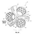
- FIG. 2is an elevation view of a hybrid earth-boring bit illustrative of the present invention.
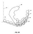
- FIG. 3is a bottom plan form view of the hybrid earth-boring bit of FIG. 2 .
- FIG. 3Ais a profile view of cutting elements of a three fixed blade cutters and cutting elements of three rolling-cutters of an embodiment of a hybrid bit of the present inventions of FIGS. 1 through 3 .
- FIG. 3Bis a profile view of cutting elements of a first fixed blade cutter and cutting elements of a first rolling-cutter of an embodiment of a hybrid bit of the present invention
- FIG. 3Cis a profile view of cutting elements of a second fixed blade cutter and cutting elements of a second rolling-cutter of an embodiment of a hybrid bit of the present invention
- FIG. 3Dis a view of cutting elements of a third fixed blade cutter and cutting elements of a third rolling-cutter of an embodiment of a hybrid bit of the present invention
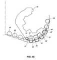
- FIG. 3Eis a view of FIG. 3 showing a pair of a rolling-cutter and a fixed blade cutter of a hybrid bit of FIG. 3 of the present invention.
- FIG. 3Fis a view of FIG. 3 showing another fixed blade cutter and another rolling-cutter of a hybrid bit of FIG. 3 of the present invention.
- FIG. 4is a bottom plan form view of another embodiment of a hybrid earth-boring bit of the present invention.
- FIGS. 5 and 6are partial schematic views of rolling-cutters and cutting elements of rolling-cutters interfacing with the formation being drilled.
- FIG. 1is a graph of rate-of-penetration (ROP on y-axis) versus weight-on-bit (WOB on x-axis) for earth-boring bits such as a fixed blade cutter bit, a hybrid bit of the present invention, and a three rolling-cutter bit (three roller cone bit).
- the data for the bits illustrated in the graphwas generated using 121 ⁇ 4/inch bits on the Hughes Christensen simulator in The Woodlands, Tex. The conditions were 4000 pounds per square inch of bottom-hole pressure, 120 bit revolutions per minute, and 9.5 pounds per gallon drilling fluid or mud while drilling Carthage marble.
- the data used and reflected in FIG. 1is intended to be general and to reflect general characteristics for the three types of bits, such as fixed blade cutter bits having PDC cutting elements, hybrid bits including variations thereof of the present inventions, and rolling-cutter bits (roller cone bits) whose cutting aggressiveness characteristics are illustrated.
- the graphshows the performance characteristics of three different types of earth-boring bits: a three rolling-cutter bit (three roller cones), a six blade fixed cutter bit having PDC cutting elements, and a “hybrid” bit having both (three) rolling-cutters and (three) fixed blade cutters.
- each type of bithas a characteristic line.
- the six fixed blade cutter bit having PDC cutting elementshas the highest ROP for a given WOB resulting in a line having the steepest slope of the line showing cutting performance of the bit.
- the PDC bitcould not be run at high weight on bit because of high vibrations of the bit.
- the three rolling-cutter bit(three roller cone bit) has the lowest ROP for a given WOB resulting in a line having the shallowest slope of the line showing cutting performance of the bit.
- the hybrid bit in the three embodiments of the present inventionexhibits intermediate ROP for a given WOB resulting in lines having an intermediate slopes of the lines showing cutting performance of the bit between the lines for the fixed blade cutter bit and the three rolling-cutter bit.
- ROIPenetration
- WOBWeight on Bit
- One aspect of the present inventionis to provide a method for the design of a hybrid earth-boring bit so that its aggressiveness characteristics can be tailored or varied to the drilling application.
- FIGS. 2 , 3 , and 4illustrate embodiments of hybrid earth-boring bits 11 according to the present invention.
- Hybrid bit 11comprises a bit body 13 that is threaded or otherwise configured at its upper extent for connection into a drill string.
- Bit body 13may be constructed of steel, or of a hard-metal (e.g., tungsten carbide) matrix material with steel inserts.
- Bit body 13has an axial center or centerline 15 that coincides with the axis of rotation of hybrid bit 11 in most instances.
- the illustrated hybrid bit 11is a 121 ⁇ 4 inch bit.
- FIG. 3is used to exemplify the techniques of adjusting the aggressiveness of a hybrid bit according to the present invention, i.e., “cutter-leading,” “blade-leading,” and “cutter-blade opposite,” as described herein.
- One of the embodiments of the hybrid bits of the present inventions illustrated in FIG. 3is likely not a desirable production hybrid bit design when the hybrid bit is an all blade-leading design because aggressiveness of the hybrid bit is too great for certain types of formations, but not all types of formations. That is, if the hybrid bit is a hybrid bit having an all blade-leading design, it acts more as a fixed blade cutter bit. As illustrated in FIG. 1 , aggressiveness of such hybrid bit is high which might adversely affect its durability and dynamic stability.
- At least one bit leg (two of three are shown in FIG. 2 ) 17 , 19 , 21depends axially downwardly from the bit body 13 .
- a lubricant compensatoris associated with each bit leg to compensate for pressure variations in the lubricant provided for the bearing.
- at least one fixed blade cutter 23 , 25 , 27depends axially downwardly from bit body 13 .
- a rolling cutter 29 , 31 , 33is mounted for rotation (typically on a journal bearing, but rolling-element or other bearings may be used as well) on each bit leg 17 , 19 , 21 .
- Each rolling-cutter 29 , 31 , 33has a plurality of cutting elements 35 , 37 , 39 arranged in generally circumferential rows thereon.
- cutting elements 35 , 37 , 39are tungsten carbide inserts, each insert having an interference fit into bores or apertures formed in each rolling cutter 29 , 31 , 33 .
- cutting elements 35 , 37 , 39can be integrally formed with the cutter and hardfaced, as in the case of steel- or milled-tooth cutters. Materials other than tungsten carbide, such as polycrystalline diamond or other super-hard or super-abrasive materials, can also be used for rolling-cutter cutting elements 35 , 37 , 39 on rolling-cutters 29 , 31 , 33 .
- a plurality of cutting elements 41 , 43 , 45are arranged in a row on the leading edge of each fixed blade cutter 23 , 25 , 27 .
- Each cutting element 41 , 43 , 45is a circular disc of polycrystalline diamond mounted to a stud of tungsten carbide or other hard metal, which is in turn soldered, brazed or otherwise secured to the leading edge of each fixed blade cutter. Thermally stable polycrystalline diamond (TSP) or other conventional fixed-blade cutting element materials may also be used.
- TSPThermally stable polycrystalline diamond
- Each row of cutting elements 41 , 43 , 45 on each of the fixed blade cutters 23 , 25 , 27extends from the central portion of bit body 13 to the radially outermost or gage portion or surface of bit body 13 .
- a cutting element 41 on a fixed-blade cutter 23is located at or near the central axis or centerline 15 of bit body 13 (“at or near” meaning some part of the fixed cutter is at or within about 0.040 inch of the centerline 15 ).
- the radially innermost cutting element 41 in the row on fixed blade cutter 23has its circumference tangent to the axial center or centerline 15 of the bit body 13 and hybrid bit 1 .
- a plurality of flat-topped, wear-resistant inserts 51 formed of tungsten carbide or similar hard metal with a polycrystalline diamond cutter attached theretoare provided on the radially outermost or gage surface of each fixed blade cutter 23 , 25 , 27 . These serve to protect this portion of the bit from abrasive wear encountered at the sidewall of the borehole. Also, a row or any desired number of rows of back-up cutters 53 is provided on each fixed blade cutter 23 , 25 , 27 between the leading and trailing edges thereof.
- Back-up cutters 53may be aligned with the main or primary cutting elements 41 , 43 , 45 on their respective fixed blade cutters 23 , 25 , 27 so that they cut in the same swath or kerf or groove as the main or primary cutting elements on a fixed blade cutter. Alternatively, they may be radially spaced apart from the main fixed-blade cutting elements so that they cut in the same swath or kerf or groove or between the same swaths or kerfs or grooves formed by the main or primary cutting elements on their respective fixed blade cutters. Additionally, back-up cutters 53 provide additional points of contact or engagement between the bit 11 and the formation being drilled, thus enhancing the stability of hybrid bit 11 .
- rolling-cutters 29 , 31 , 33can be truncated in length and are angularly spaced approximately 120 degrees apart from each other (measured between their axes of rotation).
- a first rolling-cutter 29is spaced apart 58 degrees from a first fixed blade 23 (measured between the axis of rotation of rolling cutter 29 and the centerline of fixed blade 23 in a clockwise manner in FIG. 3 ) forming a pair of cutters.
- a second rolling-cutter 31is spaced 63 degrees from a second fixed blade 25 (measured similarly) forming a pair of cutters; and a third rolling-cutter 33 is spaced 53 degrees apart from a third fixed blade 27 (again measured the same way) forming a pair of cutters.
- FIG. 3Aa cutting profile for the fixed cutting elements 41 , 45 , 43 on fixed blade cutters 23 , 25 , 27 and cutting elements 35 , 37 , 39 on rolling-cutters 29 , 33 , 31 are generally illustrated.
- an inner most cutting element 41 on fixed blade cutter 23is tangent to the axial center 15 of the bit body 13 or hybrid bit 11 .
- the innermost cutting element 43 on fixed blade cutter 27is illustrated.
- innermost cutting element 45 on fixed blade cutter 25is also illustrated.
- a cutting element 35 on rolling-cutter 29is illustrated having the same cutting depth or exposure and cutting element 41 on fixed blade cutter 23 each being located at the same centerline and cutting the same swath or kerf or groove.
- Some cutting elements 41 on fixed blade cutter 23are located in the cone of the hybrid bit 11 , while other cutting elements 41 are located in the nose and shoulder portion of the hybrid bit 11 having cutting elements 35 of rolling cutter 29 cutting the same swath or kerf or groove generally in the nose and shoulder of the hybrid bit 11 out to the gage thereof.
- Cutting elements 35 , 37 , 39 on rolling-cutters 29 , 33 , 31do not extend into the cone of the hybrid bit 11 but are generally located in the nose and shoulder of the hybrid bit 111 out to the gage of the hybrid bit. Further illustrated in FIG.
- 3Aare the cutting elements 37 , 39 on rolling-cutters 31 and 33 and their relation to the cutting elements 43 and 45 on fixed blade cutters 27 , 25 cutting the same swath or kerf or groove either being centered thereon or offset in the same swath or kerf or groove during a revolution of the hybrid drill bit 11 . While each cutting element 41 , 43 , 45 and cutting element 35 , 37 , 39 has been illustrated having the same exposure of depth of cut so that each cutting element cuts the same amount of formation, the depth of cut may be varied in the same swath or kerf or groove, if desired.
- FIG. 3BIllustrated in FIG. 3B is a cutting profile for the fixed cutting elements 41 on fixed blade cutter 23 and cutting elements 35 on rolling-cutter 29 in relation to the each other, the fixed blade cutter 23 and the rolling-cutter 29 forming a pair of cutters on hybrid bit 11 .
- some of the cutting elements 41 on fixed blade cutter 23 and cutting element 35 on rolling-cutter 29both have the same center and cut in the same swath or kerf or groove while other cutting elements 41 ′ on fixed blade cutter 23 and cutting element 35 ′ on rolling cutter 29 do not have the same center but still cut in the same swath or kerf or groove.
- all the cutting elements 41 and 41 ′ on fixed blade cutter 23 and cutting elements 35 and 35 ′ on rolling cutter 29have the same exposure to cut the same depth of formation for an equal cut of the formation during a revolution of the hybrid drill bit 11 , although this may be varied as desired.
- backup cutting elements 53 on fixed blade 23 located behind cutting elements 41may have the same exposure of cut as cutting elements 41 or less exposure of cut as cutting elements 41 and have the same diameter or a smaller diameter than a cutting element 41 .
- backup cutting elements 53 while cutting in the same swath or kerf or groove 41 ′ as a cutting element 41may be located off the center of a cutting element 41 located in front of a backup cutting element 53 associated therewith.
- cutting elements 41 and backup cutting elements 53 on fixed blade 23 and cutting elements 35 on rolling cutter 29will all cut in the same swath or kerf or groove while being either centered on each other of slightly off-centered from each other having the same exposure of cut or, in the alternative, a lesser exposure of cut.
- FIG. 3CIllustrated in FIG. 3C is a cutting profile for the fixed cutting elements 43 on fixed blade cutter 27 in relation to the cutting elements 37 on rolling-cutter 33 , the fixed blade cutter 27 and the rolling-cutter 33 forming a pair of cutters on hybrid bit 11 .
- some of the cutting elements 43 on fixed blade cutter 27 and cutting element 37 on rolling-cutter 33both have the same center and cutting in the same swath or kerf or groove while other cutting elements 43 ′ on fixed blade cutter 23 and cutting element 37 ′ on rolling cutter 33 do not have the same center but cut in the same swath or kerf or groove.
- all the cutting elements 43 and 43 ′ on fixed blade cutter 27 and cutting elements 37 and 37 ′ on rolling cutter 33have the same exposure to cut the same depth of formation for an equal cut of the formation during a revolution of the hybrid drill bit 11 , although this may be varied as desired.
- backup cutting elements 53 on fixed blade 27 located behind cutting elements 43may have the same exposure of cut as cutting elements 43 or less exposure of cut as cutting elements 43 and have the same diameter or a smaller diameter than a cutting element 43 .
- backup cutting elements 53 while cutting in the same swath or kerf or groove as a cutting element 43may be located off the center of a cutting element 43 associated therewith.
- cutting elements 43 and backup cutting elements 53 on fixed blade cutter 27 and cutting elements 37 on rolling cutter 33will all cut in the same swath or kerf or groove while being either centered on each other of slightly off-centered from each other having the same exposure of cut or, in the alternative, a lesser exposure of cut.
- FIG. 3DIllustrated in FIG. 3D is a cutting profile for the fixed cutting elements 45 on fixed blade cutter 25 in relation to cutting elements 39 on rolling-cutter 31 forming a pair of cutters on hybrid bit 11 .
- some of the cutting elements 45 on fixed blade cutter 25 and cutting element 39 on rolling-cutter 31both have the same center and cutting in the same swath or kerf or groove while other cutting elements 45 ′ on fixed blade cutter 25 and cutting element 39 ′ on rolling cutter 31 do not have the same center but cut in the same swath or kerf or groove.
- all the cutting elements 45 and 45 ′ on fixed blade cutter 25 and cutting elements 39 and 39 ′ on rolling cutter 33have the same exposure to cut the same depth of formation for an equal cut of the formation, although this may be varied as desired.
- all the cutting elements 45 and 45 ′ on fixed blade cutter 25 and cutting elements 39 and 39 ′ on rolling-cutter 31have the same exposure to cut the same depth of formation for an equal cut of the formation during a revolution of the hybrid drill bit 11 .
- backup cutting elements 53 on fixed blade 25 located behind cutting elements 45may have the same exposure of cut as cutting elements 45 or less exposure of cut as cutting elements 45 and have the same diameter or a smaller diameter than a cutting element 45 .
- backup cutting elements 53 while cutting in the same swath or kerf or groove as a cutting element 45may be located off the center of a cutting element 45 associated therewith. In this manner, cutting elements 45 and backup cutting elements 53 on fixed blade cutter 25 and cutting elements 39 on rolling cutter 31 will all cut in the same swath or kerf or groove while being either centered on each other of slightly off-centered from each other having the same exposure of cut or, in the alternative, a lesser exposure of cut.
- adjusting the angular spacing between rolling cutters 29 , 31 , 33 , and fixed blade cutters 23 , 25 , 27is one way in which to adjust the cutting aggressiveness or aggressiveness of a hybrid bit 11 according to the present invention.
- the rolling-cutter 29is the primary cutter of the pair with the fixed blade cutter 23 cutting less of the pair. Spacing a rolling cutter 29 closer to a fixed blade cutter 23 of a pair of cutters on the hybrid bit 11 causes the rolling cutter 29 to have a more dominate cutting action of the pair of cutters thereby causing the hybrid bit 11 to have less cutting aggressiveness or aggressiveness.
- Spacing a rolling-cutter 29 farther away from a fixed blade cutter 23 of a pair of cutters on the hybrid bit 11allows or causes the cutting elements of the fixed blade cutter 23 to dominate the cutting action of the pair of cutters thereby increasing the cutting aggressiveness or aggressiveness of the hybrid bit 11 .
- Another way of altering the cutting aggressiveness of a hybrid bit 11is by having a rolling cutter to lead a trailing fixed blade cutter of a pair of cutters (including one of each type of cutter) or to have a fixed blade cutter lead a trailing rolling cutter of a pair of cutters (including one of each type of cutter).
- a fixed blade cutterleads a rolling cutter of a pair of cutters of a hybrid bit 11 (see line HBLC)
- the hybrid bit 11has more cutting aggressiveness cutting more like a fixed blade cutter polycrystalline diamond (PDC) bit.
- PDCpolycrystalline diamond
- FIG. 1when a rolling cutter leads a fixed blade cutter of a pair of cutters of a hybrid bit 11 (see line HCLB), the aggressiveness decreases with the hybrid bit having aggressiveness more like a rolling-cutter (roller cone) bit.
- one rolling cutter 29“leads” its trailing fixed blade cutter 23 as a pair of cutters.
- one fixed blade cutter 25“leads” its trailing rolling cutter 33 as a pair of cutters.
- leafsit is meant that the cutting elements on the adjacent, trailing structure (whether fixed blade cutter or rolling cutter) are arranged to fall in the same swath or kerf or groove as that made by the cutting elements on the leading structure (whether a fixed blade cutter or rolling cutter), as indicated by phantom lines in FIG. 3E or FIG. 3F .
- the cutting elements 41 on fixed blade cutter 23fall in the same swath or kerf or groove (see FIG. 3A , FIG. 3B ) as the cutting elements 35 on rolling cutter 29 .
- the cutting elements 37 on rolling-cutter 33fall in the same swath or kerf or groove (see FIG. 3A , FIG. 3C ) as cutting elements 45 on fixed blade cutter 25 .
- rolling cutter 31has its cutting elements 39 arranged to lead the cutting elements 43 on the opposing (if not directly opposite, i.e., 180 degrees) fixed blade cutter 27 .
- fixed blade cutter 27 and rolling-cutter 31bear load approximately equally on the hybrid bit 11 .
- each fixed blade cuttershould be “paired” with a rolling-cutter such that the cutting elements on the paired fixed blade cutter and rolling-cutter fall in the same swath or kerf or groove when drilling a formation.
- All rolling cutterscan lead all fixed blade cutters, making a less aggressive bit (see solid line HCLB in FIG. 1 ); or all fixed blade cutters can lead all rolling-cutters, making a more aggressive bit (see broken line HBLC in FIG. 1 ), or the all cutting elements of a rolling-cutter can fall in the same swath or kerf or groove as the cutting elements on an opposing fixed blade (see broken line HCOB in FIG. 1 ), or any combination thereof on a hybrid bit of the present invention.
- FIG. 4illustrates an embodiment of the earth-boring hybrid bit 111 according to the present invention that is similar to the embodiments of FIG. 3 in all respects, except that cutting elements 135 , 137 , 139 on each of the rolling cutters— 129 , 133 , 131 respectively are arranged to cut in the same swath or kerf or groove as the cutting elements 145 , 141 , 143 on the opposite or opposing fixed blade cutters 125 , 122 , 127 respectively.
- the cutting elements 135 on rolling cutter 129fall in the same swath or kerf or groove as the cutting elements 145 on the opposing fixed blade cutter 125 .
- Thiscan be called a “cutter-opposite” arrangement of cutting elements.
- the cutting elements on a fixed blade cutter or rolling-cutter “leading” the cutting elements on a trailing rolling-cutter or fixed blade cutterrather than the cutting elements on a fixed blade cutter or rolling-cutter “leading” the cutting elements on a trailing rolling-cutter or fixed blade cutter, the cutting elements on a fixed blade cutter or rolling-cutter “oppose” those on the opposing or opposite rolling-cutter or fixed blade cutter.
- the hybrid bit 111 of FIG. 4having the “cutter-opposite” configuration of pairs of cutters, appears to be extremely stable in comparison to all configurations of “cutter-leading” pairs of cutters or all “blade-leading” pairs of cutters. Additionally, based on preliminary testing, the hybrid bit 111 of FIG. 4 out drills a conventional rolling-cutter bit and a conventional fixed blade cutter bit having polycrystalline diamond cutting elements (PDC bit), as well as other hybrid bit configurations (“cutter-leading”) in hard sandstone.
- PDC bitpolycrystalline diamond cutting elements
- a conventional 121 ⁇ 4 inch rolling-cutter bitdrills the hard sandstone at 11 feet/hour, a conventional fixed blade cutter bit having polycrystalline diamond cutting elements (PDC bit) at 13 feet/hour, the hybrid bit with “cutter-leading” pair of cutters configuration at 14 feet/hour and the hybrid bit with “cutter-opposite” pair of cutters configuration at 21 feet/hour.
- PDC bitpolycrystalline diamond cutting elements
- Different types of hard sandstoneis the material that are most difficult formations to drill using fixed blade cutter bits mainly due to high levels of scatter vibrations.
- the balanced loading resulting from the “cutter-opposite” pair of cutters configuration of a hybrid bitis believed to produce a significant difference over other types and configurations of bits.
- the aggressiveness of a hybrid bitcan be tailored or varied to the particular drilling and formation conditions encountered.
- Still another way to adjust or vary the aggressiveness of the hybrid bit 11is to arrange the cutting elements 35 , 37 , 39 on the rolling-cutters 29 , 31 , 33 so that they project deeper into the formation being drilled than the cutting elements 41 , 43 , 45 on the fixed blade cutters 23 , 25 , 27 .
- the simplest way to do thisis to adjust the projection of some or all of the cutting elements 35 , 37 , 39 on the rolling-cutters 29 , 31 , 33 from the surface of each rolling cutter 29 , 31 , 33 so that they project in the axial direction (parallel to the bit axis 15 ) further than some or all of the cutting elements 41 , 43 , 45 on fixed blades cutters 23 , 25 , 27 .
- the extra axial projection of a cutting element of the cutting elements on the rolling cutterscauses the cutting element to bear more load and protects an associated cutting element of the fixed blade cutter.
- each cutting element of a rolling-cutteris a combination of the projection of each cutting element of a rolling-cutter from the surface of its rolling cutter, combined with its angular spacing (pitch) from adjacent cutting elements that governs whether the cutting elements of a rolling-cutter actually bear more of the cutting load than an associated cutting element on a fixed blade cutter.
- This combinationis referred to herein as “effective projection,” and is illustrated in FIGS. 5 and 6 .
- the effective projection A of a given cutting element of a rolling-cutter, or that projection of the cutting element available to penetrate into earthen formationis limited by the projection of each adjacent cutting element and the angular distance or pitch C between the adjacent cutting elements and the given cutting element.
- FIG. 6illustrates “full” effective projection B in that the pitch is selected so that the adjacent cutting elements on either side of a given cutting element permit penetration of the cutting element to a depth equal to its full projection from the surface of a rolling-cutter.
- a method for designing a hybrid earth-boring bit of the present inventionpermits or allows the cutting aggressiveness of a hybrid bit to be adjusted or selected based on the relationship of at least a pair of cutters comprising a fixed blade cutter and a rolling-cutter, of a plurality of fixed blade cutters and rolling-cutters, wherein the relationship includes a fixed blade cutter leading a rolling-cutter in a pair of cutters, a rolling-cutter leading a fixed blade cutter in a pair of cutters, a rolling-cutter being located opposite a fixed blade cutter in a pair of cutters on the bit, and the angular relationship of a fixed blade cutter and a rolling-cutter of a pair of cutters regarding the amount of leading or trailing of the cutter from an associated cutter of the pair of cutters.
- the cutting aggressiveness of a hybrid bit of the present inventionbeing achieved by defining a cutting aggressiveness of a hybrid drill bit and the various combinations of pair of a fixed blade cutter and a rolling-cutter, when compared to each other and to different types of drill bits, such as a rolling-cutter drill bit and a fixed blade cutter drill bit, either as the ratio of torque to weight-on-bit or as the ratio of penetration rate to weight-on-bit.
- the cutting aggressiveness for a hybrid bit of the present inventionbeing adjusted by performing at least one of the following steps:
Landscapes
- Engineering & Computer Science (AREA)
- Life Sciences & Earth Sciences (AREA)
- Geology (AREA)
- Mining & Mineral Resources (AREA)
- Mechanical Engineering (AREA)
- Physics & Mathematics (AREA)
- Environmental & Geological Engineering (AREA)
- Fluid Mechanics (AREA)
- General Life Sciences & Earth Sciences (AREA)
- Geochemistry & Mineralogy (AREA)
- Earth Drilling (AREA)
- Excavating Of Shafts Or Tunnels (AREA)
Abstract
Description
- adjusting the angular distance between each rolling-cutter and each fixed blade cutter of a pair of cutters of the bit;
- adjusting the effective projection of the cutting elements on a rolling cutter;
- arranging the cutting elements of a fixed blade cutter and the cutting elements of a rolling-cutter so that at least one cutting element of a rolling-cutter and at least one cutting element of a fixed blade cutter cut the same swath or kerf or groove during a drilling operation; and
- arranging a pair of at least one fixed blade cutter and a rolling-cutter so that the rolling cutter either leads the fixed blade cutter [(<180°) angular distance], the rolling-cutter opposes the fixed blade cutter [(=180°) angular distance], or trails the fixed blade cutter [(>180°) angular distance].
Aggressiveness=Rate of Penetration (ROP)/Weight on Bit (WOB) (1)
Thus aggressiveness, as the mathematical slope of a line, has a value greater than zero. Measured purely in terms of aggressiveness, it would seem that fixed blade cutter bits would be selected in all instances for drilling. However, other factors come into play. For example, there are limits on the amount of WOB and torque to turn the bit that can be applied, generally based on either the drilling application or the capacity of the drill string and drilling rig. For example, as WOB on a fixed blade cutter bit increases the drill string torque requirement increase rapidly, especially with fixed blade cutter bits, and erratic torque can cause harmful vibrations. Rolling-cutter bits, on the other hand, require high WOB which, in the extreme, may buckle a bottom hole assembly or exceed the load bearing capacity of the cutter bearings of the rolling-cutters of the rolling-cutter bit. Accordingly, different types of bits, whether a fixed blade cutter bit, a rolling-cutter bit, or a hybrid bit, have different advantages in different situations. One aspect of the present invention is to provide a method for the design of a hybrid earth-boring bit so that its aggressiveness characteristics can be tailored or varied to the drilling application.
- adjusting the angular distance between each rolling-cutter and each fixed blade cutter of a pair of cutters of the bit;
- adjusting the effective projection of the cutting elements on a rolling cutter;
- arranging the cutting elements of a fixed blade and the cutting elements of a rolling-cutter so that at least one cutting element of a rolling-cutter and at least one cutting element of a fixed blade cut the same swath or kerf or groove during a drilling operation; and
- arranging a pair of at least one fixed blade cutter and a rolling-cutter so that the rolling cutter either leads the fixed blade cutter [(<180°) angular distance], the rolling cutter opposes the fixed blade cutter [(=180°) angular distance], or trails the fixed blade cutter [(>180°) angular distance].
Claims (46)
Priority Applications (3)
| Application Number | Priority Date | Filing Date | Title |
|---|---|---|---|
| US12/271,033US8678111B2 (en) | 2007-11-16 | 2008-11-14 | Hybrid drill bit and design method |
| US14/223,322US10316589B2 (en) | 2007-11-16 | 2014-03-24 | Hybrid drill bit and design method |
| US16/417,079US10871036B2 (en) | 2007-11-16 | 2019-05-20 | Hybrid drill bit and design method |
Applications Claiming Priority (2)
| Application Number | Priority Date | Filing Date | Title |
|---|---|---|---|
| US98871807P | 2007-11-16 | 2007-11-16 | |
| US12/271,033US8678111B2 (en) | 2007-11-16 | 2008-11-14 | Hybrid drill bit and design method |
Related Child Applications (1)
| Application Number | Title | Priority Date | Filing Date |
|---|---|---|---|
| US14/223,322ContinuationUS10316589B2 (en) | 2007-11-16 | 2014-03-24 | Hybrid drill bit and design method |
Publications (2)
| Publication Number | Publication Date |
|---|---|
| US20090126998A1 US20090126998A1 (en) | 2009-05-21 |
| US8678111B2true US8678111B2 (en) | 2014-03-25 |
Family
ID=40640747
Family Applications (3)
| Application Number | Title | Priority Date | Filing Date |
|---|---|---|---|
| US12/271,033ActiveUS8678111B2 (en) | 2007-11-16 | 2008-11-14 | Hybrid drill bit and design method |
| US14/223,322Active2030-12-08US10316589B2 (en) | 2007-11-16 | 2014-03-24 | Hybrid drill bit and design method |
| US16/417,079ActiveUS10871036B2 (en) | 2007-11-16 | 2019-05-20 | Hybrid drill bit and design method |
Family Applications After (2)
| Application Number | Title | Priority Date | Filing Date |
|---|---|---|---|
| US14/223,322Active2030-12-08US10316589B2 (en) | 2007-11-16 | 2014-03-24 | Hybrid drill bit and design method |
| US16/417,079ActiveUS10871036B2 (en) | 2007-11-16 | 2019-05-20 | Hybrid drill bit and design method |
Country Status (1)
| Country | Link |
|---|---|
| US (3) | US8678111B2 (en) |
Cited By (13)
| Publication number | Priority date | Publication date | Assignee | Title |
|---|---|---|---|---|
| US20130199856A1 (en)* | 2012-02-08 | 2013-08-08 | Baker Hughes Incorporated | Shaped cutting elements for earth-boring tools and earth-boring tools including such cutting elements |
| US9458674B2 (en) | 2010-08-06 | 2016-10-04 | Baker Hughes Incorporated | Earth-boring tools including shaped cutting elements, and related methods |
| US9976353B2 (en) | 2014-06-18 | 2018-05-22 | Halliburton Energy Services, Inc. | Rolling element assemblies |
| US10012029B2 (en) | 2015-12-18 | 2018-07-03 | Baker Hughes, A Ge Company, Llc | Rolling cones with gage cutting elements, earth-boring tools carrying rolling cones with gage cutting elements and related methods |
| US10337272B2 (en) | 2016-02-16 | 2019-07-02 | Varel International Ind., L.P. | Hybrid roller cone and junk mill bit |
| US10557311B2 (en) | 2015-07-17 | 2020-02-11 | Halliburton Energy Services, Inc. | Hybrid drill bit with counter-rotation cutters in center |
| US10760342B2 (en) | 2016-10-05 | 2020-09-01 | Halliburton Energy Services, Inc. | Rolling element assembly with a compliant retainer |
| US10876360B2 (en) | 2016-02-26 | 2020-12-29 | Halliburton Energy Services, Inc. | Hybrid drill bit with axially adjustable counter rotation cutters in center |
| US10995557B2 (en) | 2017-11-08 | 2021-05-04 | Halliburton Energy Services, Inc. | Method of manufacturing and designing a hybrid drill bit |
| US11015396B2 (en) | 2016-06-17 | 2021-05-25 | Halliburton Energy Services, Inc. | Rolling element with half lock-wedge lock |
| CN113107371A (en)* | 2021-03-30 | 2021-07-13 | 中国石油大学(华东) | Self-excitation shaft-impacting and induced unloading coupling rock breaking drill bit and drilling speed increasing method |
| US12065883B2 (en) | 2020-09-29 | 2024-08-20 | Schlumberger Technology Corporation | Hybrid bit |
| US12084919B2 (en) | 2019-05-21 | 2024-09-10 | Schlumberger Technology Corporation | Hybrid bit |
Families Citing this family (40)
| Publication number | Priority date | Publication date | Assignee | Title |
|---|---|---|---|---|
| US7841426B2 (en) | 2007-04-05 | 2010-11-30 | Baker Hughes Incorporated | Hybrid drill bit with fixed cutters as the sole cutting elements in the axial center of the drill bit |
| US7845435B2 (en) | 2007-04-05 | 2010-12-07 | Baker Hughes Incorporated | Hybrid drill bit and method of drilling |
| US8678111B2 (en) | 2007-11-16 | 2014-03-25 | Baker Hughes Incorporated | Hybrid drill bit and design method |
| US20120205160A1 (en) | 2011-02-11 | 2012-08-16 | Baker Hughes Incorporated | System and method for leg retention on hybrid bits |
| US20090272582A1 (en)* | 2008-05-02 | 2009-11-05 | Baker Hughes Incorporated | Modular hybrid drill bit |
| US7819208B2 (en) | 2008-07-25 | 2010-10-26 | Baker Hughes Incorporated | Dynamically stable hybrid drill bit |
| US9439277B2 (en) | 2008-10-23 | 2016-09-06 | Baker Hughes Incorporated | Robotically applied hardfacing with pre-heat |
| US8948917B2 (en) | 2008-10-29 | 2015-02-03 | Baker Hughes Incorporated | Systems and methods for robotic welding of drill bits |
| US8450637B2 (en) | 2008-10-23 | 2013-05-28 | Baker Hughes Incorporated | Apparatus for automated application of hardfacing material to drill bits |
| US20100122848A1 (en)* | 2008-11-20 | 2010-05-20 | Baker Hughes Incorporated | Hybrid drill bit |
| MX2011006187A (en) | 2008-12-31 | 2011-06-20 | Baker Hughes Inc | Method and apparatus for automated application of hardfacing material to rolling cutters of hybrid-type earth boring drill bits, hybrid drill bits comprising such hardfaced steel-toothed cutting elements, and methods of use thereof. |
| US8141664B2 (en) | 2009-03-03 | 2012-03-27 | Baker Hughes Incorporated | Hybrid drill bit with high bearing pin angles |
| US8056651B2 (en) | 2009-04-28 | 2011-11-15 | Baker Hughes Incorporated | Adaptive control concept for hybrid PDC/roller cone bits |
| US8459378B2 (en) | 2009-05-13 | 2013-06-11 | Baker Hughes Incorporated | Hybrid drill bit |
| US8157026B2 (en) | 2009-06-18 | 2012-04-17 | Baker Hughes Incorporated | Hybrid bit with variable exposure |
| CA2773897A1 (en) | 2009-09-16 | 2011-03-24 | Baker Hughes Incorporated | External, divorced pdc bearing assemblies for hybrid drill bits |
| WO2011038383A2 (en)* | 2009-09-28 | 2011-03-31 | Bake Hughes Incorporated | Earth-boring tools, methods of making earth-boring tools and methods of drilling with earth-boring tools |
| US8347989B2 (en) | 2009-10-06 | 2013-01-08 | Baker Hughes Incorporated | Hole opener with hybrid reaming section and method of making |
| US8448724B2 (en) | 2009-10-06 | 2013-05-28 | Baker Hughes Incorporated | Hole opener with hybrid reaming section |
| US8505634B2 (en)* | 2009-12-28 | 2013-08-13 | Baker Hughes Incorporated | Earth-boring tools having differing cutting elements on a blade and related methods |
| WO2011084944A2 (en)* | 2010-01-05 | 2011-07-14 | Smith International, Inc. | High-shear roller cone and pdc hybrid bit |
| US8794356B2 (en)* | 2010-02-05 | 2014-08-05 | Baker Hughes Incorporated | Shaped cutting elements on drill bits and other earth-boring tools, and methods of forming same |
| US8851207B2 (en) | 2011-05-05 | 2014-10-07 | Baker Hughes Incorporated | Earth-boring tools and methods of forming such earth-boring tools |
| CN103080458B (en) | 2010-06-29 | 2016-01-20 | 贝克休斯公司 | Drill bit with anti-drill bit recycling groove structure |
| US8978786B2 (en) | 2010-11-04 | 2015-03-17 | Baker Hughes Incorporated | System and method for adjusting roller cone profile on hybrid bit |
| US9782857B2 (en) | 2011-02-11 | 2017-10-10 | Baker Hughes Incorporated | Hybrid drill bit having increased service life |
| WO2013074788A1 (en)* | 2011-11-15 | 2013-05-23 | Baker Hughes Incorporated | Hybrid drill bits having increased drilling efficiency |
| CN103015899B (en)* | 2012-12-19 | 2015-07-29 | 江汉石油钻头股份有限公司 | A kind of Mixed drilling bit strengthening heart portion cutting function |
| US9376866B2 (en)* | 2013-08-23 | 2016-06-28 | Varel International Ind., L.P. | Hybrid rotary cone drill bit |
| WO2015102891A1 (en)* | 2013-12-31 | 2015-07-09 | Smith International, Inc. | Multi-piece body manufacturing method of hybrid bit |
| CN103758457B (en)* | 2014-01-17 | 2016-11-09 | 湖南天鹰科技集团有限公司 | A kind of combination rock bit |
| RU2689465C2 (en) | 2014-05-23 | 2019-05-28 | Бейкер Хьюз Инкорпорейтед | Combined drill bit with mechanical fastening of rock drilling unit elements |
| US11428050B2 (en) | 2014-10-20 | 2022-08-30 | Baker Hughes Holdings Llc | Reverse circulation hybrid bit |
| US10196859B2 (en) | 2016-03-04 | 2019-02-05 | Baker Hughes Incorporated | Drill bits, rotatable cutting structures, cutting structures having adjustable rotational resistance, and related methods |
| CN108798514B (en)* | 2017-04-27 | 2024-01-05 | 西南石油大学 | Directional drilling diamond drill bit |
| CN106869802B (en)* | 2017-04-27 | 2023-10-27 | 西南石油大学 | A composite rock-breaking mechanism and a long-life composite drill bit |
| CN107143287A (en)* | 2017-07-14 | 2017-09-08 | 宜昌神达石油机械有限公司 | Yangtze Cambrian system shale gas exploitation combined bitses during one kind is applicable |
| US10907414B2 (en)* | 2017-11-09 | 2021-02-02 | Baker Hughes, A Ge Company, Llc | Earth boring tools having fixed blades and varying sized rotatable cutting structures and related methods |
| CN107747473B (en)* | 2017-11-16 | 2024-04-16 | 中石化江钻石油机械有限公司 | Insert cone hybrid bit |
| CN112031661B (en)* | 2020-10-15 | 2024-10-29 | 四川职业技术学院 | Drill bit with anti-sticking bores structure |
Citations (238)
| Publication number | Priority date | Publication date | Assignee | Title |
|---|---|---|---|---|
| US930759A (en) | 1908-11-20 | 1909-08-10 | Howard R Hughes | Drill. |
| US1388424A (en) | 1919-06-27 | 1921-08-23 | Edward A George | Rotary bit |
| US1394769A (en) | 1920-05-18 | 1921-10-25 | C E Reed | Drill-head for oil-wells |
| US1519641A (en) | 1920-10-12 | 1924-12-16 | Walter N Thompson | Rotary underreamer |
| US1816568A (en) | 1929-06-05 | 1931-07-28 | Reed Roller Bit Co | Drill bit |
| US1821474A (en) | 1927-12-05 | 1931-09-01 | Sullivan Machinery Co | Boring tool |
| US1874066A (en) | 1930-04-28 | 1932-08-30 | Floyd L Scott | Combination rolling and scraping cutter drill |
| US1879127A (en) | 1930-07-21 | 1932-09-27 | Hughes Tool Co | Combination rolling and scraping cutter bit |
| US1896243A (en) | 1928-04-12 | 1933-02-07 | Hughes Tool Co | Cutter support for well drills |
| US1932487A (en) | 1930-07-11 | 1933-10-31 | Hughes Tool Co | Combination scraping and rolling cutter drill |
| US2030722A (en) | 1933-12-01 | 1936-02-11 | Hughes Tool Co | Cutter assembly |
| US2117481A (en) | 1935-02-19 | 1938-05-17 | Globe Oil Tools Co | Rock core drill head |
| US2119618A (en) | 1937-08-28 | 1938-06-07 | John A Zublin | Oversize hole drilling mechanism |
| US2198849A (en) | 1938-06-09 | 1940-04-30 | Reuben L Waxler | Drill |
| US2216894A (en) | 1939-10-12 | 1940-10-08 | Reed Roller Bit Co | Rock bit |
| US2244537A (en) | 1939-12-22 | 1941-06-03 | Archer W Kammerer | Well drilling bit |
| US2297157A (en) | 1940-11-16 | 1942-09-29 | Mcclinton John | Drill |
| US2320137A (en) | 1941-08-12 | 1943-05-25 | Archer W Kammerer | Rotary drill bit |
| US2320136A (en) | 1940-09-30 | 1943-05-25 | Archer W Kammerer | Well drilling bit |
| US2380112A (en) | 1942-01-02 | 1945-07-10 | Kinnear Clarence Wellington | Drill |
| USRE23416E (en) | 1951-10-16 | Drill | ||
| US2719026A (en) | 1952-04-28 | 1955-09-27 | Reed Roller Bit Co | Earth boring drill |
| US2815932A (en) | 1956-02-29 | 1957-12-10 | Norman E Wolfram | Retractable rock drill bit apparatus |
| US2994389A (en) | 1957-06-07 | 1961-08-01 | Le Bus Royalty Company | Combined drilling and reaming apparatus |
| US3010708A (en) | 1960-04-11 | 1961-11-28 | Goodman Mfg Co | Rotary mining head and core breaker therefor |
| US3050293A (en) | 1960-05-12 | 1962-08-21 | Goodman Mfg Co | Rotary mining head and core breaker therefor |
| US3055443A (en) | 1960-05-31 | 1962-09-25 | Jersey Prod Res Co | Drill bit |
| US3066749A (en) | 1959-08-10 | 1962-12-04 | Jersey Prod Res Co | Combination drill bit |
| US3126067A (en) | 1964-03-24 | Roller bit with inserts | ||
| US3126066A (en) | 1964-03-24 | Rotary drill bit with wiper blade | ||
| US3174564A (en) | 1963-06-10 | 1965-03-23 | Hughes Tool Co | Combination core bit |
| US3239431A (en) | 1963-02-21 | 1966-03-08 | Knapp Seth Raymond | Rotary well bits |
| US3250337A (en) | 1963-10-29 | 1966-05-10 | Max J Demo | Rotary shock wave drill bit |
| US3269469A (en) | 1964-01-10 | 1966-08-30 | Hughes Tool Co | Solid head rotary-percussion bit with rolling cutters |
| US3387673A (en) | 1966-03-15 | 1968-06-11 | Ingersoll Rand Co | Rotary percussion gang drill |
| US3424258A (en) | 1966-11-16 | 1969-01-28 | Japan Petroleum Dev Corp | Rotary bit for use in rotary drilling |
| DE1301784B (en) | 1968-01-27 | 1969-08-28 | Deutsche Erdoel Ag | Combination bit for plastic rock |
| US3583501A (en) | 1969-03-06 | 1971-06-08 | Mission Mfg Co | Rock bit with powered gauge cutter |
| USRE28625E (en) | 1970-08-03 | 1975-11-25 | Rock drill with increased bearing life | |
| US4006788A (en) | 1975-06-11 | 1977-02-08 | Smith International, Inc. | Diamond cutter rock bit with penetration limiting |
| US4140189A (en) | 1977-06-06 | 1979-02-20 | Smith International, Inc. | Rock bit with diamond reamer to maintain gage |
| US4190126A (en) | 1976-12-28 | 1980-02-26 | Tokiwa Industrial Co., Ltd. | Rotary abrasive drilling bit |
| US4270812A (en) | 1977-07-08 | 1981-06-02 | Thomas Robert D | Drill bit bearing |
| US4285409A (en) | 1979-06-28 | 1981-08-25 | Smith International, Inc. | Two cone bit with extended diamond cutters |
| US4293048A (en) | 1980-01-25 | 1981-10-06 | Smith International, Inc. | Jet dual bit |
| US4320808A (en) | 1980-06-24 | 1982-03-23 | Garrett Wylie P | Rotary drill bit |
| US4343371A (en) | 1980-04-28 | 1982-08-10 | Smith International, Inc. | Hybrid rock bit |
| US4359112A (en) | 1980-06-19 | 1982-11-16 | Smith International, Inc. | Hybrid diamond insert platform locator and retention method |
| US4369849A (en) | 1980-06-05 | 1983-01-25 | Reed Rock Bit Company | Large diameter oil well drilling bit |
| US4386669A (en) | 1980-12-08 | 1983-06-07 | Evans Robert F | Drill bit with yielding support and force applying structure for abrasion cutting elements |
| US4410284A (en) | 1982-04-22 | 1983-10-18 | Smith International, Inc. | Composite floating element thrust bearing |
| US4428687A (en) | 1981-05-11 | 1984-01-31 | Hughes Tool Company | Floating seal for earth boring bit |
| US4444281A (en) | 1983-03-30 | 1984-04-24 | Reed Rock Bit Company | Combination drag and roller cutter drill bit |
| WO1985002223A1 (en) | 1983-11-18 | 1985-05-23 | Rock Bit Industries U.S.A., Inc. | Hybrid rock bit |
| US4527637A (en) | 1981-05-11 | 1985-07-09 | Bodine Albert G | Cycloidal drill bit |
| US4572306A (en) | 1984-12-07 | 1986-02-25 | Dorosz Dennis D E | Journal bushing drill bit construction |
| US4657091A (en) | 1985-05-06 | 1987-04-14 | Robert Higdon | Drill bits with cone retention means |
| US4664705A (en) | 1985-07-30 | 1987-05-12 | Sii Megadiamond, Inc. | Infiltrated thermally stable polycrystalline diamond |
| GB2183694A (en) | 1985-11-23 | 1987-06-10 | Nl Petroleum Prod | Improvements in or relating to rotary drill bits |
| SU1331988A1 (en) | 1985-07-12 | 1987-08-23 | И.И. Барабашкин, И. В. Воевидко и В. М. Ивасив | Well calibrator |
| US4690228A (en) | 1986-03-14 | 1987-09-01 | Eastman Christensen Company | Changeover bit for extended life, varied formations and steady wear |
| US4706765A (en) | 1986-08-11 | 1987-11-17 | Four E Inc. | Drill bit assembly |
| US4726718A (en) | 1984-03-26 | 1988-02-23 | Eastman Christensen Co. | Multi-component cutting element using triangular, rectangular and higher order polyhedral-shaped polycrystalline diamond disks |
| US4727942A (en) | 1986-11-05 | 1988-03-01 | Hughes Tool Company | Compensator for earth boring bits |
| US4738322A (en) | 1984-12-21 | 1988-04-19 | Smith International Inc. | Polycrystalline diamond bearing system for a roller cone rock bit |
| US4765205A (en) | 1987-06-01 | 1988-08-23 | Bob Higdon | Method of assembling drill bits and product assembled thereby |
| US4874047A (en) | 1988-07-21 | 1989-10-17 | Cummins Engine Company, Inc. | Method and apparatus for retaining roller cone of drill bit |
| US4875532A (en) | 1988-09-19 | 1989-10-24 | Dresser Industries, Inc. | Roller drill bit having radial-thrust pilot bushing incorporating anti-galling material |
| EP0157278B1 (en) | 1984-03-26 | 1989-11-02 | Eastman Christensen Company | Multi-component cutting element using polycrystalline diamond disks |
| US4892159A (en) | 1988-11-29 | 1990-01-09 | Exxon Production Research Company | Kerf-cutting apparatus and method for improved drilling rates |
| US4915181A (en) | 1987-12-14 | 1990-04-10 | Jerome Labrosse | Tubing bit opener |
| US4932484A (en) | 1989-04-10 | 1990-06-12 | Amoco Corporation | Whirl resistant bit |
| US4936398A (en) | 1989-07-07 | 1990-06-26 | Cledisc International B.V. | Rotary drilling device |
| US4943488A (en) | 1986-10-20 | 1990-07-24 | Norton Company | Low pressure bonding of PCD bodies and method for drill bits and the like |
| US4953641A (en) | 1989-04-27 | 1990-09-04 | Hughes Tool Company | Two cone bit with non-opposite cones |
| US4976324A (en) | 1989-09-22 | 1990-12-11 | Baker Hughes Incorporated | Drill bit having diamond film cutting surface |
| US4981184A (en)* | 1988-11-21 | 1991-01-01 | Smith International, Inc. | Diamond drag bit for soft formations |
| US4984643A (en) | 1990-03-21 | 1991-01-15 | Hughes Tool Company | Anti-balling earth boring bit |
| US4991671A (en) | 1990-03-13 | 1991-02-12 | Camco International Inc. | Means for mounting a roller cutter on a drill bit |
| US5016718A (en) | 1989-01-26 | 1991-05-21 | Geir Tandberg | Combination drill bit |
| US5028177A (en) | 1984-03-26 | 1991-07-02 | Eastman Christensen Company | Multi-component cutting element using triangular, rectangular and higher order polyhedral-shaped polycrystalline diamond disks |
| US5027912A (en) | 1988-07-06 | 1991-07-02 | Baker Hughes Incorporated | Drill bit having improved cutter configuration |
| US5030276A (en) | 1986-10-20 | 1991-07-09 | Norton Company | Low pressure bonding of PCD bodies and method |
| US5049164A (en) | 1990-01-05 | 1991-09-17 | Norton Company | Multilayer coated abrasive element for bonding to a backing |
| US5116568A (en) | 1986-10-20 | 1992-05-26 | Norton Company | Method for low pressure bonding of PCD bodies |
| US5145017A (en) | 1991-01-07 | 1992-09-08 | Exxon Production Research Company | Kerf-cutting apparatus for increased drilling rates |
| US5224560A (en) | 1990-10-30 | 1993-07-06 | Modular Engineering | Modular drill bit |
| US5238074A (en) | 1992-01-06 | 1993-08-24 | Baker Hughes Incorporated | Mosaic diamond drag bit cutter having a nonuniform wear pattern |
| US5287936A (en) | 1992-01-31 | 1994-02-22 | Baker Hughes Incorporated | Rolling cone bit with shear cutting gage |
| US5289889A (en) | 1993-01-21 | 1994-03-01 | Marvin Gearhart | Roller cone core bit with spiral stabilizers |
| US5337843A (en) | 1992-02-17 | 1994-08-16 | Kverneland Klepp As | Hole opener for the top hole section of oil/gas wells |
| US5346026A (en) | 1992-01-31 | 1994-09-13 | Baker Hughes Incorporated | Rolling cone bit with shear cutting gage |
| US5351770A (en) | 1993-06-15 | 1994-10-04 | Smith International, Inc. | Ultra hard insert cutters for heel row rotary cone rock bit applications |
| US5361859A (en) | 1993-02-12 | 1994-11-08 | Baker Hughes Incorporated | Expandable gage bit for drilling and method of drilling |
| US5429200A (en) | 1994-03-31 | 1995-07-04 | Dresser Industries, Inc. | Rotary drill bit with improved cutter |
| US5439068A (en) | 1994-08-08 | 1995-08-08 | Dresser Industries, Inc. | Modular rotary drill bit |
| US5452771A (en) | 1994-03-31 | 1995-09-26 | Dresser Industries, Inc. | Rotary drill bit with improved cutter and seal protection |
| US5467836A (en) | 1992-01-31 | 1995-11-21 | Baker Hughes Incorporated | Fixed cutter bit with shear cutting gage |
| US5472057A (en) | 1994-04-11 | 1995-12-05 | Atlantic Richfield Company | Drilling with casing and retrievable bit-motor assembly |
| US5472271A (en) | 1993-04-26 | 1995-12-05 | Newell Operating Company | Hinge for inset doors |
| EP0391683B1 (en) | 1989-04-05 | 1996-01-10 | De Beers Industrial Diamond Division (Pty) Limited | Drilling |
| US5513715A (en) | 1994-08-31 | 1996-05-07 | Dresser Industries, Inc. | Flat seal for a roller cone rock bit |
| US5531281A (en)* | 1993-07-16 | 1996-07-02 | Camco Drilling Group Ltd. | Rotary drilling tools |
| US5547033A (en) | 1994-12-07 | 1996-08-20 | Dresser Industries, Inc. | Rotary cone drill bit and method for enhanced lifting of fluids and cuttings |
| US5553681A (en) | 1994-12-07 | 1996-09-10 | Dresser Industries, Inc. | Rotary cone drill bit with angled ramps |
| US5558170A (en) | 1992-12-23 | 1996-09-24 | Baroid Technology, Inc. | Method and apparatus for improving drill bit stability |
| US5560440A (en) | 1993-02-12 | 1996-10-01 | Baker Hughes Incorporated | Bit for subterranean drilling fabricated from separately-formed major components |
| US5570750A (en) | 1995-04-20 | 1996-11-05 | Dresser Industries, Inc. | Rotary drill bit with improved shirttail and seal protection |
| US5593231A (en) | 1995-01-17 | 1997-01-14 | Dresser Industries, Inc. | Hydrodynamic bearing |
| US5606895A (en) | 1994-08-08 | 1997-03-04 | Dresser Industries, Inc. | Method for manufacture and rebuild a rotary drill bit |
| US5641029A (en) | 1995-06-06 | 1997-06-24 | Dresser Industries, Inc. | Rotary cone drill bit modular arm |
| USD384084S (en) | 1995-09-12 | 1997-09-23 | Dresser Industries, Inc. | Rotary cone drill bit |
| US5695018A (en) | 1995-09-13 | 1997-12-09 | Baker Hughes Incorporated | Earth-boring bit with negative offset and inverted gage cutting elements |
| US5695019A (en) | 1995-08-23 | 1997-12-09 | Dresser Industries, Inc. | Rotary cone drill bit with truncated rolling cone cutters and dome area cutter inserts |
| US5755297A (en) | 1994-12-07 | 1998-05-26 | Dresser Industries, Inc. | Rotary cone drill bit with integral stabilizers |
| US5862871A (en) | 1996-02-20 | 1999-01-26 | Ccore Technology & Licensing Limited, A Texas Limited Partnership | Axial-vortex jet drilling system and method |
| US5868502A (en) | 1996-03-26 | 1999-02-09 | Smith International, Inc. | Thrust disc bearings for rotary cone air bits |
| US5873422A (en) | 1992-05-15 | 1999-02-23 | Baker Hughes Incorporated | Anti-whirl drill bit |
| US5941322A (en) | 1991-10-21 | 1999-08-24 | The Charles Machine Works, Inc. | Directional boring head with blade assembly |
| US5944125A (en) | 1997-06-19 | 1999-08-31 | Varel International, Inc. | Rock bit with improved thrust face |
| US5967246A (en) | 1995-10-10 | 1999-10-19 | Camco International (Uk) Limited | Rotary drill bits |
| US5988303A (en) | 1996-11-12 | 1999-11-23 | Dresser Industries, Inc. | Gauge face inlay for bit hardfacing |
| US5992542A (en) | 1996-03-01 | 1999-11-30 | Rives; Allen Kent | Cantilevered hole opener |
| US5996713A (en) | 1995-01-26 | 1999-12-07 | Baker Hughes Incorporated | Rolling cutter bit with improved rotational stabilization |
| JP2000080878A (en) | 1998-06-30 | 2000-03-21 | Kyoei Kogyo Kk | Drilling head for combined use with hard and soft formations |
| US6095265A (en) | 1997-08-15 | 2000-08-01 | Smith International, Inc. | Impregnated drill bits with adaptive matrix |
| US6109375A (en) | 1998-02-23 | 2000-08-29 | Dresser Industries, Inc. | Method and apparatus for fabricating rotary cone drill bits |
| US6116357A (en) | 1996-09-09 | 2000-09-12 | Smith International, Inc. | Rock drill bit with back-reaming protection |
| US6173797B1 (en) | 1997-09-08 | 2001-01-16 | Baker Hughes Incorporated | Rotary drill bits for directional drilling employing movable cutters and tandem gage pad arrangement with active cutting elements and having up-drill capability |
| US6220374B1 (en) | 1998-01-26 | 2001-04-24 | Dresser Industries, Inc. | Rotary cone drill bit with enhanced thrust bearing flange |
| US6241034B1 (en) | 1996-06-21 | 2001-06-05 | Smith International, Inc. | Cutter element with expanded crest geometry |
| US6241036B1 (en) | 1998-09-16 | 2001-06-05 | Baker Hughes Incorporated | Reinforced abrasive-impregnated cutting elements, drill bits including same |
| JP2001159289A (en) | 1999-12-03 | 2001-06-12 | Tobishima Corp | Drilling head |
| US6250407B1 (en) | 1998-12-18 | 2001-06-26 | Sandvik Ab | Rotary drill bit having filling opening for the installation of cylindrical bearings |
| US6260635B1 (en) | 1998-01-26 | 2001-07-17 | Dresser Industries, Inc. | Rotary cone drill bit with enhanced journal bushing |
| US6279671B1 (en) | 1999-03-01 | 2001-08-28 | Amiya K. Panigrahi | Roller cone bit with improved seal gland design |
| US6283233B1 (en) | 1996-12-16 | 2001-09-04 | Dresser Industries, Inc | Drilling and/or coring tool |
| US6296069B1 (en) | 1996-12-16 | 2001-10-02 | Dresser Industries, Inc. | Bladed drill bit with centrally distributed diamond cutters |
| USRE37450E1 (en) | 1988-06-27 | 2001-11-20 | The Charles Machine Works, Inc. | Directional multi-blade boring head |
| US6345673B1 (en)* | 1998-11-20 | 2002-02-12 | Smith International, Inc. | High offset bits with super-abrasive cutters |
| US6360831B1 (en) | 1999-03-09 | 2002-03-26 | Halliburton Energy Services, Inc. | Borehole opener |
| US6367568B2 (en) | 1997-09-04 | 2002-04-09 | Smith International, Inc. | Steel tooth cutter element with expanded crest |
| US6386302B1 (en) | 1999-09-09 | 2002-05-14 | Smith International, Inc. | Polycrystaline diamond compact insert reaming tool |
| US6401844B1 (en) | 1998-12-03 | 2002-06-11 | Baker Hughes Incorporated | Cutter with complex superabrasive geometry and drill bits so equipped |
| US6405811B1 (en) | 2000-09-18 | 2002-06-18 | Baker Hughes Corporation | Solid lubricant for air cooled drill bit and method of drilling |
| US6408958B1 (en) | 2000-10-23 | 2002-06-25 | Baker Hughes Incorporated | Superabrasive cutting assemblies including cutters of varying orientations and drill bits so equipped |
| US6415687B2 (en) | 1998-07-13 | 2002-07-09 | Dresser Industries, Inc. | Rotary cone drill bit with machined cutting structure and method |
| US20020092684A1 (en) | 2000-06-07 | 2002-07-18 | Smith International, Inc. | Hydro-lifter rock bit with PDC inserts |
| US20020108785A1 (en) | 2001-02-13 | 2002-08-15 | Slaughter Robert Harlan | Back reaming tool |
| US6439326B1 (en) | 2000-04-10 | 2002-08-27 | Smith International, Inc. | Centered-leg roller cone drill bit |
| US6446739B1 (en) | 1999-07-19 | 2002-09-10 | Smith International, Inc. | Rock drill bit with neck protection |
| US6450270B1 (en) | 1999-09-24 | 2002-09-17 | Robert L. Saxton | Rotary cone bit for cutting removal |
| US6460635B1 (en) | 1999-10-25 | 2002-10-08 | Kalsi Engineering, Inc. | Load responsive hydrodynamic bearing |
| US6474424B1 (en) | 1998-03-26 | 2002-11-05 | Halliburton Energy Services, Inc. | Rotary cone drill bit with improved bearing system |
| US6510909B2 (en) | 1996-04-10 | 2003-01-28 | Smith International, Inc. | Rolling cone bit with gage and off-gage cutter elements positioned to separate sidewall and bottom hole cutting duty |
| US6510906B1 (en) | 1999-11-29 | 2003-01-28 | Baker Hughes Incorporated | Impregnated bit with PDC cutters in cone area |
| US6527066B1 (en) | 1999-05-14 | 2003-03-04 | Allen Kent Rives | Hole opener with multisized, replaceable arms and cutters |
| US6533051B1 (en) | 1999-09-07 | 2003-03-18 | Smith International, Inc. | Roller cone drill bit shale diverter |
| US6544308B2 (en) | 2000-09-20 | 2003-04-08 | Camco International (Uk) Limited | High volume density polycrystalline diamond with working surfaces depleted of catalyzing material |
| US6568490B1 (en) | 1998-02-23 | 2003-05-27 | Halliburton Energy Services, Inc. | Method and apparatus for fabricating rotary cone drill bits |
| US6581700B2 (en) | 2000-09-19 | 2003-06-24 | Curlett Family Ltd Partnership | Formation cutting method and system |
| US6601662B2 (en) | 2000-09-20 | 2003-08-05 | Grant Prideco, L.P. | Polycrystalline diamond cutters with working surfaces having varied wear resistance while maintaining impact strength |
| US6601661B2 (en) | 2001-09-17 | 2003-08-05 | Baker Hughes Incorporated | Secondary cutting structure |
| US6684967B2 (en) | 1999-08-05 | 2004-02-03 | Smith International, Inc. | Side cutting gage pad improving stabilization and borehole integrity |
| US20040099448A1 (en) | 2002-11-21 | 2004-05-27 | Fielder Coy M. | Sub-reamer for bi-center type tools |
| US6742607B2 (en) | 2002-05-28 | 2004-06-01 | Smith International, Inc. | Fixed blade fixed cutter hole opener |
| US6745858B1 (en) | 2001-08-24 | 2004-06-08 | Rock Bit International | Adjustable earth boring device |
| US6823951B2 (en) | 2002-07-03 | 2004-11-30 | Smith International, Inc. | Arcuate-shaped inserts for drill bits |
| EP0874128B1 (en) | 1997-04-26 | 2004-12-01 | Camco International (UK) Limited | Rotary drill bit having movable formation-engaging members |
| US20040238224A1 (en) | 2001-07-06 | 2004-12-02 | Runia Douwe Johannes | Well drilling bit |
| US6843333B2 (en) | 1999-11-29 | 2005-01-18 | Baker Hughes Incorporated | Impregnated rotary drag bit |
| US6883623B2 (en) | 2002-10-09 | 2005-04-26 | Baker Hughes Incorporated | Earth boring apparatus and method offering improved gage trimmer protection |
| US20050087370A1 (en) | 2003-10-22 | 2005-04-28 | Ledgerwood Leroy W.Iii | Increased projection for compacts of a rolling cone drill bit |
| US20050103533A1 (en) | 2003-11-17 | 2005-05-19 | Sherwood William H.Jr. | Cutting element retention apparatus for use in steel body rotary drill bits, steel body rotary drill bits so equipped, and method of manufacture and repair therefor |
| US6902014B1 (en) | 2002-08-01 | 2005-06-07 | Rock Bit L.P. | Roller cone bi-center bit |
| US20050178587A1 (en) | 2004-01-23 | 2005-08-18 | Witman George B.Iv | Cutting structure for single roller cone drill bit |
| US20050183892A1 (en) | 2004-02-19 | 2005-08-25 | Oldham Jack T. | Casing and liner drilling bits, cutting elements therefor, and methods of use |
| US20050263328A1 (en) | 2004-05-06 | 2005-12-01 | Smith International, Inc. | Thermally stable diamond bonded materials and compacts |
| US20050273301A1 (en) | 2000-03-13 | 2005-12-08 | Smith International, Inc. | Techniques for modeling/simulating, designing optimizing, and displaying hybrid drill bits |
| US6986395B2 (en) | 1998-08-31 | 2006-01-17 | Halliburton Energy Services, Inc. | Force-balanced roller-cone bits, systems, drilling methods, and design methods |
| US20060032677A1 (en) | 2003-02-12 | 2006-02-16 | Smith International, Inc. | Novel bits and cutting structures |
| US20060032674A1 (en) | 2004-08-16 | 2006-02-16 | Shilin Chen | Roller cone drill bits with optimized bearing structures |
| US20060162969A1 (en) | 2005-01-25 | 2006-07-27 | Smith International, Inc. | Cutting elements formed from ultra hard materials having an enhanced construction |
| US7096978B2 (en) | 1999-08-26 | 2006-08-29 | Baker Hughes Incorporated | Drill bits with reduced exposure of cutters |
| US20060196699A1 (en) | 2005-03-04 | 2006-09-07 | Roy Estes | Modular kerfing drill bit |
| US20060254830A1 (en) | 2005-05-16 | 2006-11-16 | Smith International, Inc. | Thermally stable diamond brazing |
| US7137460B2 (en) | 2001-02-13 | 2006-11-21 | Smith International, Inc. | Back reaming tool |
| US20060266559A1 (en) | 2005-05-26 | 2006-11-30 | Smith International, Inc. | Polycrystalline diamond materials having improved abrasion resistance, thermal stability and impact resistance |
| US20060266558A1 (en) | 2005-05-26 | 2006-11-30 | Smith International, Inc. | Thermally stable ultra-hard material compact construction |
| US20060278442A1 (en) | 2005-06-13 | 2006-12-14 | Kristensen Henry L | Drill bit |
| US20060283640A1 (en) | 2003-06-20 | 2006-12-21 | Roy Estes | Stepped polycrystalline diamond compact insert |
| US7152702B1 (en) | 2005-11-04 | 2006-12-26 | Smith International, Inc. | Modular system for a back reamer and method |
| US20070029114A1 (en) | 2005-08-03 | 2007-02-08 | Smith International, Inc. | Polycrystalline diamond composite constructions comprising thermally stable diamond volume |
| US20070062736A1 (en) | 2005-09-21 | 2007-03-22 | Smith International, Inc. | Hybrid disc bit with optimized PDC cutter placement |
| US7197806B2 (en) | 2003-02-12 | 2007-04-03 | Hewlett-Packard Development Company, L.P. | Fastener for variable mounting |
| US7198119B1 (en) | 2005-11-21 | 2007-04-03 | Hall David R | Hydraulic drill bit assembly |
| US20070079994A1 (en) | 2005-10-12 | 2007-04-12 | Smith International, Inc. | Diamond-bonded bodies and compacts with improved thermal stability and mechanical strength |
| US7234550B2 (en) | 2003-02-12 | 2007-06-26 | Smith International, Inc. | Bits and cutting structures |
| US20070187155A1 (en) | 2006-02-09 | 2007-08-16 | Smith International, Inc. | Thermally stable ultra-hard polycrystalline materials and compacts |
| US20070221417A1 (en) | 2006-03-23 | 2007-09-27 | Hall David R | Jack Element in Communication with an Electric Motor and or Generator |
| US7281592B2 (en) | 2001-07-23 | 2007-10-16 | Shell Oil Company | Injecting a fluid into a borehole ahead of the bit |
| US7320375B2 (en) | 2005-07-19 | 2008-01-22 | Smith International, Inc. | Split cone bit |
| US20080066970A1 (en) | 2005-03-25 | 2008-03-20 | Baker Hughes Incorporated | Rotary drill bits |
| US7350568B2 (en) | 2005-02-09 | 2008-04-01 | Halliburton Energy Services, Inc. | Logging a well |
| US7387177B2 (en) | 2006-10-18 | 2008-06-17 | Baker Hughes Incorporated | Bearing insert sleeve for roller cone bit |
| US7392862B2 (en) | 2006-01-06 | 2008-07-01 | Baker Hughes Incorporated | Seal insert ring for roller cone bits |
| US7398837B2 (en) | 2005-11-21 | 2008-07-15 | Hall David R | Drill bit assembly with a logging device |
| US7416036B2 (en) | 2005-08-12 | 2008-08-26 | Baker Hughes Incorporated | Latchable reaming bit |
| US7435478B2 (en) | 2005-01-27 | 2008-10-14 | Smith International, Inc. | Cutting structures |
| WO2008124572A1 (en) | 2007-04-05 | 2008-10-16 | Baker Hughes Incorporated | Hybrid drill bit and method of drilling |
| US20080296068A1 (en) | 2007-04-05 | 2008-12-04 | Baker Hughes Incorporated | Hybrid drill bit with fixed cutters as the sole cutting elements in the axial center of the drill bit |
| US7473287B2 (en) | 2003-12-05 | 2009-01-06 | Smith International Inc. | Thermally-stable polycrystalline diamond materials and compacts |
| US7517589B2 (en) | 2004-09-21 | 2009-04-14 | Smith International, Inc. | Thermally stable diamond polycrystalline diamond constructions |
| US20090120693A1 (en) | 2007-11-14 | 2009-05-14 | Mcclain Eric E | Earth-boring tools attachable to a casing string and methods for their manufacture |
| US7533740B2 (en) | 2005-02-08 | 2009-05-19 | Smith International Inc. | Thermally stable polycrystalline diamond cutting elements and bits incorporating the same |
| US20090126998A1 (en) | 2007-11-16 | 2009-05-21 | Zahradnik Anton F | Hybrid drill bit and design method |
| US20090159341A1 (en) | 2007-12-21 | 2009-06-25 | Baker Hughes Incorporated | Reamer with balanced cutting structures for use in a wellbore |
| US20090159338A1 (en) | 2007-12-21 | 2009-06-25 | Baker Hughes Incorporated | Reamer With Improved Hydraulics For Use In A Wellbore |
| US20090166093A1 (en) | 2007-12-21 | 2009-07-02 | Baker Hughes Incorporated | Reamer With Stabilizers For Use In A Wellbore |
| US7568534B2 (en) | 2004-10-23 | 2009-08-04 | Reedhycalog Uk Limited | Dual-edge working surfaces for polycrystalline diamond cutting elements |
| EP2089187A1 (en) | 2006-11-20 | 2009-08-19 | US Synthetic Corporation | Methods of fabricating superabrasive articles |
| US20090272582A1 (en) | 2008-05-02 | 2009-11-05 | Baker Hughes Incorporated | Modular hybrid drill bit |
| US7621346B1 (en) | 2008-09-26 | 2009-11-24 | Baker Hughes Incorporated | Hydrostatic bearing |
| US7621348B2 (en) | 2006-10-02 | 2009-11-24 | Smith International, Inc. | Drag bits with dropping tendencies and methods for making the same |
| US7703556B2 (en) | 2008-06-04 | 2010-04-27 | Baker Hughes Incorporated | Methods of attaching a shank to a body of an earth-boring tool including a load-bearing joint and tools formed by such methods |
| US7703557B2 (en) | 2007-06-11 | 2010-04-27 | Smith International, Inc. | Fixed cutter bit with backup cutter elements on primary blades |
| US20100224417A1 (en) | 2009-03-03 | 2010-09-09 | Baker Hughes Incorporated | Hybrid drill bit with high bearing pin angles |
| US7819208B2 (en) | 2008-07-25 | 2010-10-26 | Baker Hughes Incorporated | Dynamically stable hybrid drill bit |
| US20100276205A1 (en) | 2005-11-10 | 2010-11-04 | Baker Hughes Incorporated | Methods of forming earth-boring rotary drill bits |
| US20100288561A1 (en) | 2009-05-13 | 2010-11-18 | Baker Hughes Incorporated | Hybrid drill bit |
| US7836975B2 (en) | 2007-10-24 | 2010-11-23 | Schlumberger Technology Corporation | Morphable bit |
| US7845437B2 (en) | 2009-02-13 | 2010-12-07 | Century Products, Inc. | Hole opener assembly and a cone arm forming a part thereof |
| US7847437B2 (en) | 2007-07-30 | 2010-12-07 | Gm Global Technology Operations, Inc. | Efficient operating point for double-ended inverter system |
| US20100320001A1 (en) | 2009-06-18 | 2010-12-23 | Baker Hughes Incorporated | Hybrid bit with variable exposure |
| US20110024197A1 (en) | 2009-07-31 | 2011-02-03 | Smith International, Inc. | High shear roller cone drill bits |
| US20110079441A1 (en) | 2009-10-06 | 2011-04-07 | Baker Hughes Incorporated | Hole opener with hybrid reaming section |
| US20110079443A1 (en) | 2009-10-06 | 2011-04-07 | Baker Hughes Incorporated | Hole opener with hybrid reaming section |
| US20110162893A1 (en) | 2010-01-05 | 2011-07-07 | Smith International, Inc. | High-shear roller cone and pdc hybrid bit |
Family Cites Families (108)
| Publication number | Priority date | Publication date | Assignee | Title |
|---|---|---|---|---|
| US874128A (en) | 1907-04-15 | 1907-12-17 | Oscar Smith | Attachment for self-propelled vehicles. |
| US1537550A (en) | 1923-01-13 | 1925-05-12 | Reed Roller Bit Co | Lubricator for deep-well-drilling apparatus |
| US1729062A (en) | 1927-08-15 | 1929-09-24 | Reed Roller Bit Co | Roller-cutter mounting |
| US1801720A (en) | 1927-11-26 | 1931-04-21 | Reed Roller Bit Co | Roller bit |
| US2089187A (en) | 1935-05-18 | 1937-08-10 | Celanese Corp | Preparation and use of textile threads |
| US2204657A (en) | 1938-07-12 | 1940-06-18 | Brendel Clyde | Roller bit |
| US2184067A (en) | 1939-01-03 | 1939-12-19 | John A Zublin | Drill bit |
| US2318370A (en) | 1940-12-06 | 1943-05-04 | Kasner M | Oil well drilling bit |
| US2358642A (en) | 1941-11-08 | 1944-09-19 | Archer W Kammerer | Rotary drill bit |
| US2533258A (en) | 1945-11-09 | 1950-12-12 | Hughes Tool Co | Drill cutter |
| US2533259A (en) | 1946-06-28 | 1950-12-12 | Hughes Tool Co | Cluster tooth cutter |
| US2520517A (en) | 1946-10-25 | 1950-08-29 | Manley L Natland | Apparatus for drilling wells |
| US2557302A (en) | 1947-12-12 | 1951-06-19 | Aubrey F Maydew | Combination drag and rotary drilling bit |
| US2575438A (en) | 1949-09-28 | 1951-11-20 | Kennametal Inc | Percussion drill bit body |
| US2628821A (en) | 1950-10-07 | 1953-02-17 | Kennametal Inc | Percussion drill bit body |
| US2661931A (en) | 1950-12-04 | 1953-12-08 | Security Engineering Division | Hydraulic rotary rock bit |
| US2725215A (en) | 1953-05-05 | 1955-11-29 | Donald B Macneir | Rotary rock drilling tool |
| US3039503A (en) | 1960-08-17 | 1962-06-19 | Nell C Mainone | Means for mounting cutter blades on a cylindrical cutterhead |
| US3397751A (en) | 1966-03-02 | 1968-08-20 | Continental Oil Co | Asymmetric three-cone rock bit |
| US3760894A (en) | 1971-11-10 | 1973-09-25 | M Pitifer | Replaceable blade drilling bits |
| SE7701680L (en) | 1977-02-16 | 1978-08-17 | Skf Ab | AXIAL BEARING FOR A ROLL IN A ROLL DRILL CROWN SW 77 004 SW |
| US4108259A (en) | 1977-05-23 | 1978-08-22 | Smith International, Inc. | Raise drill with removable stem |
| US4187922A (en) | 1978-05-12 | 1980-02-12 | Dresser Industries, Inc. | Varied pitch rotary rock bit |
| DE2960568D1 (en) | 1978-05-30 | 1981-11-05 | Grootcon Uk Ltd | Method of welding metal parts |
| US4260203A (en) | 1979-09-10 | 1981-04-07 | Smith International, Inc. | Bearing structure for a rotary rock bit |
| US4408671A (en) | 1980-04-24 | 1983-10-11 | Munson Beauford E | Roller cone drill bit |
| US4359114A (en) | 1980-12-10 | 1982-11-16 | Robbins Machine, Inc. | Raise drill bit inboard cutter assembly |
| US4456082A (en) | 1981-05-18 | 1984-06-26 | Smith International, Inc. | Expandable rock bit |
| US4468138A (en) | 1981-09-28 | 1984-08-28 | Maurer Engineering Inc. | Manufacture of diamond bearings |
| US4448269A (en) | 1981-10-27 | 1984-05-15 | Hitachi Construction Machinery Co., Ltd. | Cutter head for pit-boring machine |
| SE446646B (en) | 1981-12-15 | 1986-09-29 | Santrade Ltd | MOUNTAIN DRILL AND WANT TO MANUFACTURE THIS |
| US4527644A (en) | 1983-03-25 | 1985-07-09 | Allam Farouk M | Drilling bit |
| US4525178A (en) | 1984-04-16 | 1985-06-25 | Megadiamond Industries, Inc. | Composite polycrystalline diamond |
| SE457656B (en) | 1984-06-18 | 1989-01-16 | Santrade Ltd | BORRKRONA INCLUDING AND ROTATING CUTTING ROLLS AND DRILL HEADS INCLUDING SUCH AS BORRKRONA |
| US4802539A (en) | 1984-12-21 | 1989-02-07 | Smith International, Inc. | Polycrystalline diamond bearing system for a roller cone rock bit |
| US4600064A (en) | 1985-02-25 | 1986-07-15 | Hughes Tool Company | Earth boring bit with bearing sleeve |
| GB2194571B (en) | 1986-08-13 | 1990-05-16 | A Z Int Tool Co | Drilling apparatus and cutter |
| US4865137A (en) | 1986-08-13 | 1989-09-12 | Drilex Systems, Inc. | Drilling apparatus and cutter |
| DE3709836C1 (en) | 1987-03-25 | 1988-09-29 | Eastman Christensen Co | Plain bearings for deep drilling tools |
| US4763736A (en) | 1987-07-08 | 1988-08-16 | Varel Manufacturing Company | Asymmetrical rotary cone bit |
| US4756631A (en) | 1987-07-24 | 1988-07-12 | Smith International, Inc. | Diamond bearing for high-speed drag bits |
| US4825964A (en) | 1987-08-24 | 1989-05-02 | Rives Allen K | Arrangement for reducing seal damage between rotatable and stationary members |
| US4819703A (en) | 1988-05-23 | 1989-04-11 | Verle L. Rice | Blade mount for planar head |
| US4880068A (en) | 1988-11-21 | 1989-11-14 | Varel Manufacturing Company | Rotary drill bit locking mechanism |
| US5027914A (en) | 1990-06-04 | 1991-07-02 | Wilson Steve B | Pilot casing mill |
| US5137097A (en) | 1990-10-30 | 1992-08-11 | Modular Engineering | Modular drill bit |
| US5199516A (en) | 1990-10-30 | 1993-04-06 | Modular Engineering | Modular drill bit |
| US5037212A (en) | 1990-11-29 | 1991-08-06 | Smith International, Inc. | Bearing structure for downhole motors |
| US5092687A (en) | 1991-06-04 | 1992-03-03 | Anadrill, Inc. | Diamond thrust bearing and method for manufacturing same |
| US5253939A (en) | 1991-11-22 | 1993-10-19 | Anadrill, Inc. | High performance bearing pad for thrust bearing |
| US5342129A (en) | 1992-03-30 | 1994-08-30 | Dennis Tool Company | Bearing assembly with sidewall-brazed PCD plugs |
| DE4301784A1 (en) | 1993-01-23 | 1994-08-11 | Mabeg Kreuschner Gmbh | Apparatus for presenting pieces of information or the like |
| US6068070A (en) | 1997-09-03 | 2000-05-30 | Baker Hughes Incorporated | Diamond enhanced bearing for earth-boring bit |
| US6045029A (en) | 1993-04-16 | 2000-04-04 | Baker Hughes Incorporated | Earth-boring bit with improved rigid face seal |
| US6209185B1 (en) | 1993-04-16 | 2001-04-03 | Baker Hughes Incorporated | Earth-boring bit with improved rigid face seal |
| US5439067B1 (en) | 1994-08-08 | 1997-03-04 | Dresser Ind | Rock bit with enhanced fluid return area |
| US5595255A (en) | 1994-08-08 | 1997-01-21 | Dresser Industries, Inc. | Rotary cone drill bit with improved support arms |
| US5494123A (en) | 1994-10-04 | 1996-02-27 | Smith International, Inc. | Drill bit with protruding insert stabilizers |
| US5839526A (en) | 1997-04-04 | 1998-11-24 | Smith International, Inc. | Rolling cone steel tooth bit with enhancements in cutter shape and placement |
| US6321862B1 (en) | 1997-09-08 | 2001-11-27 | Baker Hughes Incorporated | Rotary drill bits for directional drilling employing tandem gage pad arrangement with cutting elements and up-drill capability |
| AU1075499A (en) | 1997-10-14 | 1999-05-03 | Harry Morales Campos Jr. | Rock bit with improved nozzle placement |
| US6190050B1 (en) | 1999-06-22 | 2001-02-20 | Camco International, Inc. | System and method for preparing wear-resistant bearing surfaces |
| US6170582B1 (en) | 1999-07-01 | 2001-01-09 | Smith International, Inc. | Rock bit cone retention system |
| JP2001026944A (en) | 1999-07-16 | 2001-01-30 | Kobelco Contstruction Machinery Ltd | Exhaust system structure for construction equipment |
| JP2001295576A (en) | 2000-04-12 | 2001-10-26 | Japan National Oil Corp | Bit device |
| US6922925B2 (en) | 2000-12-01 | 2005-08-02 | Hitachi Construction Machinery Co., Ltd. | Construction machine |
| US6561291B2 (en) | 2000-12-27 | 2003-05-13 | Smith International, Inc. | Roller cone drill bit structure having improved journal angle and journal offset |
| US6427791B1 (en) | 2001-01-19 | 2002-08-06 | The United States Of America As Represented By The United States Department Of Energy | Drill bit assembly for releasably retaining a drill bit cutter |
| GB0102160D0 (en) | 2001-01-27 | 2001-03-14 | Schlumberger Holdings | Cutting structure for earth boring drill bits |
| US6684966B2 (en) | 2001-10-18 | 2004-02-03 | Baker Hughes Incorporated | PCD face seal for earth-boring bit |
| US20040031625A1 (en) | 2002-08-19 | 2004-02-19 | Lin Chih C. | DLC coating for earth-boring bit bearings |
| AU2003900227A0 (en) | 2003-01-20 | 2003-02-06 | Transco Manufacturing Australia Pty Ltd | Attachment means for drilling equipment |
| US7234549B2 (en) | 2003-05-27 | 2007-06-26 | Smith International Inc. | Methods for evaluating cutting arrangements for drill bits and their application to roller cone drill bit designs |
| US7195086B2 (en) | 2004-01-30 | 2007-03-27 | Anna Victorovna Aaron | Anti-tracking earth boring bit with selected varied pitch for overbreak optimization and vibration reduction |
| US7434632B2 (en) | 2004-03-02 | 2008-10-14 | Halliburton Energy Services, Inc. | Roller cone drill bits with enhanced drilling stability and extended life of associated bearings and seals |
| US20050252691A1 (en) | 2004-03-19 | 2005-11-17 | Smith International, Inc. | Drill bit having increased resistance to fatigue cracking and method of producing same |
| US7628230B2 (en) | 2004-08-05 | 2009-12-08 | Baker Hughes Incorporated | Wide groove roller cone bit |
| US7686104B2 (en) | 2005-08-15 | 2010-03-30 | Smith International, Inc. | Rolling cone drill bit having cutter elements positioned in a plurality of differing radial positions |
| US7703982B2 (en) | 2005-08-26 | 2010-04-27 | Us Synthetic Corporation | Bearing apparatuses, systems including same, and related methods |
| US7559695B2 (en) | 2005-10-11 | 2009-07-14 | Us Synthetic Corporation | Bearing apparatuses, systems including same, and related methods |
| US7624825B2 (en) | 2005-10-18 | 2009-12-01 | Smith International, Inc. | Drill bit and cutter element having aggressive leading side |
| CA2571062A1 (en) | 2005-12-14 | 2007-06-14 | Smith International, Inc. | Rolling cone drill bit having non-uniform legs |
| US7621345B2 (en) | 2006-04-03 | 2009-11-24 | Baker Hughes Incorporated | High density row on roller cone bit |
| WO2007127899A2 (en) | 2006-04-28 | 2007-11-08 | Halliburton Energy Services, Inc. | Molds and methods of forming molds associated with manufacture of rotary drill bits and other downhole tools |
| WO2007140010A2 (en) | 2006-05-26 | 2007-12-06 | Baker Hughes Incorporated | Cutting structure for earth-boring bit to reduce tracking |
| GB2438520B (en) | 2006-05-26 | 2009-01-28 | Smith International | Drill Bit |
| JP4988848B2 (en) | 2006-09-07 | 2012-08-01 | ボルボ トラックス ノース アメリカ | Truck exhaust diffuser |
| US8177000B2 (en) | 2006-12-21 | 2012-05-15 | Sandvik Intellectual Property Ab | Modular system for a back reamer and method |
| US8205692B2 (en) | 2007-01-03 | 2012-06-26 | Smith International, Inc. | Rock bit and inserts with a chisel crest having a broadened region |
| US7631709B2 (en) | 2007-01-03 | 2009-12-15 | Smith International, Inc. | Drill bit and cutter element having chisel crest with protruding pilot portion |
| US7681673B2 (en) | 2007-06-12 | 2010-03-23 | Smith International, Inc. | Drill bit and cutting element having multiple cutting edges |
| US7823664B2 (en) | 2007-08-17 | 2010-11-02 | Baker Hughes Incorporated | Corrosion protection for head section of earth boring bit |
| US8028773B2 (en) | 2008-01-16 | 2011-10-04 | Smith International, Inc. | Drill bit and cutter element having a fluted geometry |
| US20090236147A1 (en) | 2008-03-20 | 2009-09-24 | Baker Hughes Incorporated | Lubricated Diamond Bearing Drill Bit |
| US20120205160A1 (en) | 2011-02-11 | 2012-08-16 | Baker Hughes Incorporated | System and method for leg retention on hybrid bits |
| US7861805B2 (en) | 2008-05-15 | 2011-01-04 | Baker Hughes Incorporated | Conformal bearing for rock drill bit |
| US7992658B2 (en) | 2008-11-11 | 2011-08-09 | Baker Hughes Incorporated | Pilot reamer with composite framework |
| US20100155146A1 (en) | 2008-12-19 | 2010-06-24 | Baker Hughes Incorporated | Hybrid drill bit with high pilot-to-journal diameter ratio |
| US8056651B2 (en) | 2009-04-28 | 2011-11-15 | Baker Hughes Incorporated | Adaptive control concept for hybrid PDC/roller cone bits |
| MX2011011806A (en) | 2009-05-08 | 2011-12-08 | Transco Mfg Australia Pty Ltd | Drilling equipment and attachment means for the same. |
| US8567531B2 (en) | 2009-05-20 | 2013-10-29 | Smith International, Inc. | Cutting elements, methods for manufacturing such cutting elements, and tools incorporating such cutting elements |
| US8302709B2 (en) | 2009-06-22 | 2012-11-06 | Sandvik Intellectual Property Ab | Downhole tool leg retention methods and apparatus |
| US20110085877A1 (en) | 2009-10-12 | 2011-04-14 | Atlas Copco Secoroc Llc. | Downhole tool |
| US8201646B2 (en) | 2009-11-20 | 2012-06-19 | Edward Vezirian | Method and apparatus for a true geometry, durable rotating drill bit |
| CN103080458B (en) | 2010-06-29 | 2016-01-20 | 贝克休斯公司 | Drill bit with anti-drill bit recycling groove structure |
| US8978786B2 (en) | 2010-11-04 | 2015-03-17 | Baker Hughes Incorporated | System and method for adjusting roller cone profile on hybrid bit |
| US9782857B2 (en) | 2011-02-11 | 2017-10-10 | Baker Hughes Incorporated | Hybrid drill bit having increased service life |
| WO2015102891A1 (en) | 2013-12-31 | 2015-07-09 | Smith International, Inc. | Multi-piece body manufacturing method of hybrid bit |
- 2008
- 2008-11-14USUS12/271,033patent/US8678111B2/enactiveActive
- 2014
- 2014-03-24USUS14/223,322patent/US10316589B2/enactiveActive
- 2019
- 2019-05-20USUS16/417,079patent/US10871036B2/enactiveActive
Patent Citations (273)
| Publication number | Priority date | Publication date | Assignee | Title |
|---|---|---|---|---|
| US3126066A (en) | 1964-03-24 | Rotary drill bit with wiper blade | ||
| USRE23416E (en) | 1951-10-16 | Drill | ||
| US3126067A (en) | 1964-03-24 | Roller bit with inserts | ||
| US930759A (en) | 1908-11-20 | 1909-08-10 | Howard R Hughes | Drill. |
| US1388424A (en) | 1919-06-27 | 1921-08-23 | Edward A George | Rotary bit |
| US1394769A (en) | 1920-05-18 | 1921-10-25 | C E Reed | Drill-head for oil-wells |
| US1519641A (en) | 1920-10-12 | 1924-12-16 | Walter N Thompson | Rotary underreamer |
| US1821474A (en) | 1927-12-05 | 1931-09-01 | Sullivan Machinery Co | Boring tool |
| US1896243A (en) | 1928-04-12 | 1933-02-07 | Hughes Tool Co | Cutter support for well drills |
| US1816568A (en) | 1929-06-05 | 1931-07-28 | Reed Roller Bit Co | Drill bit |
| US1874066A (en) | 1930-04-28 | 1932-08-30 | Floyd L Scott | Combination rolling and scraping cutter drill |
| US1932487A (en) | 1930-07-11 | 1933-10-31 | Hughes Tool Co | Combination scraping and rolling cutter drill |
| US1879127A (en) | 1930-07-21 | 1932-09-27 | Hughes Tool Co | Combination rolling and scraping cutter bit |
| US2030722A (en) | 1933-12-01 | 1936-02-11 | Hughes Tool Co | Cutter assembly |
| US2117481A (en) | 1935-02-19 | 1938-05-17 | Globe Oil Tools Co | Rock core drill head |
| US2119618A (en) | 1937-08-28 | 1938-06-07 | John A Zublin | Oversize hole drilling mechanism |
| US2198849A (en) | 1938-06-09 | 1940-04-30 | Reuben L Waxler | Drill |
| US2216894A (en) | 1939-10-12 | 1940-10-08 | Reed Roller Bit Co | Rock bit |
| US2244537A (en) | 1939-12-22 | 1941-06-03 | Archer W Kammerer | Well drilling bit |
| US2320136A (en) | 1940-09-30 | 1943-05-25 | Archer W Kammerer | Well drilling bit |
| US2297157A (en) | 1940-11-16 | 1942-09-29 | Mcclinton John | Drill |
| US2320137A (en) | 1941-08-12 | 1943-05-25 | Archer W Kammerer | Rotary drill bit |
| US2380112A (en) | 1942-01-02 | 1945-07-10 | Kinnear Clarence Wellington | Drill |
| US2719026A (en) | 1952-04-28 | 1955-09-27 | Reed Roller Bit Co | Earth boring drill |
| US2815932A (en) | 1956-02-29 | 1957-12-10 | Norman E Wolfram | Retractable rock drill bit apparatus |
| US2994389A (en) | 1957-06-07 | 1961-08-01 | Le Bus Royalty Company | Combined drilling and reaming apparatus |
| US3066749A (en) | 1959-08-10 | 1962-12-04 | Jersey Prod Res Co | Combination drill bit |
| US3010708A (en) | 1960-04-11 | 1961-11-28 | Goodman Mfg Co | Rotary mining head and core breaker therefor |
| US3050293A (en) | 1960-05-12 | 1962-08-21 | Goodman Mfg Co | Rotary mining head and core breaker therefor |
| US3055443A (en) | 1960-05-31 | 1962-09-25 | Jersey Prod Res Co | Drill bit |
| US3239431A (en) | 1963-02-21 | 1966-03-08 | Knapp Seth Raymond | Rotary well bits |
| US3174564A (en) | 1963-06-10 | 1965-03-23 | Hughes Tool Co | Combination core bit |
| US3250337A (en) | 1963-10-29 | 1966-05-10 | Max J Demo | Rotary shock wave drill bit |
| US3269469A (en) | 1964-01-10 | 1966-08-30 | Hughes Tool Co | Solid head rotary-percussion bit with rolling cutters |
| US3387673A (en) | 1966-03-15 | 1968-06-11 | Ingersoll Rand Co | Rotary percussion gang drill |
| US3424258A (en) | 1966-11-16 | 1969-01-28 | Japan Petroleum Dev Corp | Rotary bit for use in rotary drilling |
| DE1301784B (en) | 1968-01-27 | 1969-08-28 | Deutsche Erdoel Ag | Combination bit for plastic rock |
| US3583501A (en) | 1969-03-06 | 1971-06-08 | Mission Mfg Co | Rock bit with powered gauge cutter |
| USRE28625E (en) | 1970-08-03 | 1975-11-25 | Rock drill with increased bearing life | |
| US4006788A (en) | 1975-06-11 | 1977-02-08 | Smith International, Inc. | Diamond cutter rock bit with penetration limiting |
| US4190126A (en) | 1976-12-28 | 1980-02-26 | Tokiwa Industrial Co., Ltd. | Rotary abrasive drilling bit |
| US4140189A (en) | 1977-06-06 | 1979-02-20 | Smith International, Inc. | Rock bit with diamond reamer to maintain gage |
| US4270812A (en) | 1977-07-08 | 1981-06-02 | Thomas Robert D | Drill bit bearing |
| US4285409A (en) | 1979-06-28 | 1981-08-25 | Smith International, Inc. | Two cone bit with extended diamond cutters |
| US4293048A (en) | 1980-01-25 | 1981-10-06 | Smith International, Inc. | Jet dual bit |
| US4343371A (en) | 1980-04-28 | 1982-08-10 | Smith International, Inc. | Hybrid rock bit |
| US4369849A (en) | 1980-06-05 | 1983-01-25 | Reed Rock Bit Company | Large diameter oil well drilling bit |
| US4359112A (en) | 1980-06-19 | 1982-11-16 | Smith International, Inc. | Hybrid diamond insert platform locator and retention method |
| US4320808A (en) | 1980-06-24 | 1982-03-23 | Garrett Wylie P | Rotary drill bit |
| US4386669A (en) | 1980-12-08 | 1983-06-07 | Evans Robert F | Drill bit with yielding support and force applying structure for abrasion cutting elements |
| US4428687A (en) | 1981-05-11 | 1984-01-31 | Hughes Tool Company | Floating seal for earth boring bit |
| US4527637A (en) | 1981-05-11 | 1985-07-09 | Bodine Albert G | Cycloidal drill bit |
| US4410284A (en) | 1982-04-22 | 1983-10-18 | Smith International, Inc. | Composite floating element thrust bearing |
| US4444281A (en) | 1983-03-30 | 1984-04-24 | Reed Rock Bit Company | Combination drag and roller cutter drill bit |
| WO1985002223A1 (en) | 1983-11-18 | 1985-05-23 | Rock Bit Industries U.S.A., Inc. | Hybrid rock bit |
| US4726718A (en) | 1984-03-26 | 1988-02-23 | Eastman Christensen Co. | Multi-component cutting element using triangular, rectangular and higher order polyhedral-shaped polycrystalline diamond disks |
| US5028177A (en) | 1984-03-26 | 1991-07-02 | Eastman Christensen Company | Multi-component cutting element using triangular, rectangular and higher order polyhedral-shaped polycrystalline diamond disks |
| EP0157278B1 (en) | 1984-03-26 | 1989-11-02 | Eastman Christensen Company | Multi-component cutting element using polycrystalline diamond disks |
| US4572306A (en) | 1984-12-07 | 1986-02-25 | Dorosz Dennis D E | Journal bushing drill bit construction |
| US4738322A (en) | 1984-12-21 | 1988-04-19 | Smith International Inc. | Polycrystalline diamond bearing system for a roller cone rock bit |
| US4657091A (en) | 1985-05-06 | 1987-04-14 | Robert Higdon | Drill bits with cone retention means |
| SU1331988A1 (en) | 1985-07-12 | 1987-08-23 | И.И. Барабашкин, И. В. Воевидко и В. М. Ивасив | Well calibrator |
| US4664705A (en) | 1985-07-30 | 1987-05-12 | Sii Megadiamond, Inc. | Infiltrated thermally stable polycrystalline diamond |
| GB2183694A (en) | 1985-11-23 | 1987-06-10 | Nl Petroleum Prod | Improvements in or relating to rotary drill bits |
| EP0225101A3 (en) | 1985-11-23 | 1988-09-21 | Nl Petroleum Products Limited | Improvements in or relating to drill bits |
| US4690228A (en) | 1986-03-14 | 1987-09-01 | Eastman Christensen Company | Changeover bit for extended life, varied formations and steady wear |
| US4706765A (en) | 1986-08-11 | 1987-11-17 | Four E Inc. | Drill bit assembly |
| US4943488A (en) | 1986-10-20 | 1990-07-24 | Norton Company | Low pressure bonding of PCD bodies and method for drill bits and the like |
| US5116568A (en) | 1986-10-20 | 1992-05-26 | Norton Company | Method for low pressure bonding of PCD bodies |
| US5030276A (en) | 1986-10-20 | 1991-07-09 | Norton Company | Low pressure bonding of PCD bodies and method |
| US4727942A (en) | 1986-11-05 | 1988-03-01 | Hughes Tool Company | Compensator for earth boring bits |
| US4765205A (en) | 1987-06-01 | 1988-08-23 | Bob Higdon | Method of assembling drill bits and product assembled thereby |
| US4915181A (en) | 1987-12-14 | 1990-04-10 | Jerome Labrosse | Tubing bit opener |
| USRE37450E1 (en) | 1988-06-27 | 2001-11-20 | The Charles Machine Works, Inc. | Directional multi-blade boring head |
| US5027912A (en) | 1988-07-06 | 1991-07-02 | Baker Hughes Incorporated | Drill bit having improved cutter configuration |
| US4874047A (en) | 1988-07-21 | 1989-10-17 | Cummins Engine Company, Inc. | Method and apparatus for retaining roller cone of drill bit |
| US4875532A (en) | 1988-09-19 | 1989-10-24 | Dresser Industries, Inc. | Roller drill bit having radial-thrust pilot bushing incorporating anti-galling material |
| US4981184A (en)* | 1988-11-21 | 1991-01-01 | Smith International, Inc. | Diamond drag bit for soft formations |
| US4892159A (en) | 1988-11-29 | 1990-01-09 | Exxon Production Research Company | Kerf-cutting apparatus and method for improved drilling rates |
| US5016718A (en) | 1989-01-26 | 1991-05-21 | Geir Tandberg | Combination drill bit |
| US5176212A (en) | 1989-01-26 | 1993-01-05 | Geir Tandberg | Combination drill bit |
| EP0391683B1 (en) | 1989-04-05 | 1996-01-10 | De Beers Industrial Diamond Division (Pty) Limited | Drilling |
| US4932484A (en) | 1989-04-10 | 1990-06-12 | Amoco Corporation | Whirl resistant bit |
| US4953641A (en) | 1989-04-27 | 1990-09-04 | Hughes Tool Company | Two cone bit with non-opposite cones |
| US4936398A (en) | 1989-07-07 | 1990-06-26 | Cledisc International B.V. | Rotary drilling device |
| US4976324A (en) | 1989-09-22 | 1990-12-11 | Baker Hughes Incorporated | Drill bit having diamond film cutting surface |
| US5049164A (en) | 1990-01-05 | 1991-09-17 | Norton Company | Multilayer coated abrasive element for bonding to a backing |
| US4991671A (en) | 1990-03-13 | 1991-02-12 | Camco International Inc. | Means for mounting a roller cutter on a drill bit |
| US4984643A (en) | 1990-03-21 | 1991-01-15 | Hughes Tool Company | Anti-balling earth boring bit |
| US5224560A (en) | 1990-10-30 | 1993-07-06 | Modular Engineering | Modular drill bit |
| US5145017A (en) | 1991-01-07 | 1992-09-08 | Exxon Production Research Company | Kerf-cutting apparatus for increased drilling rates |
| US5941322A (en) | 1991-10-21 | 1999-08-24 | The Charles Machine Works, Inc. | Directional boring head with blade assembly |
| US5238074A (en) | 1992-01-06 | 1993-08-24 | Baker Hughes Incorporated | Mosaic diamond drag bit cutter having a nonuniform wear pattern |
| US5287936A (en) | 1992-01-31 | 1994-02-22 | Baker Hughes Incorporated | Rolling cone bit with shear cutting gage |
| US5346026A (en) | 1992-01-31 | 1994-09-13 | Baker Hughes Incorporated | Rolling cone bit with shear cutting gage |
| US5655612A (en) | 1992-01-31 | 1997-08-12 | Baker Hughes Inc. | Earth-boring bit with shear cutting gage |
| US5467836A (en) | 1992-01-31 | 1995-11-21 | Baker Hughes Incorporated | Fixed cutter bit with shear cutting gage |
| US5337843A (en) | 1992-02-17 | 1994-08-16 | Kverneland Klepp As | Hole opener for the top hole section of oil/gas wells |
| US5873422A (en) | 1992-05-15 | 1999-02-23 | Baker Hughes Incorporated | Anti-whirl drill bit |
| US5979576A (en) | 1992-05-15 | 1999-11-09 | Baker Hughes Incorporated | Anti-whirl drill bit |
| US5558170A (en) | 1992-12-23 | 1996-09-24 | Baroid Technology, Inc. | Method and apparatus for improving drill bit stability |
| US5289889A (en) | 1993-01-21 | 1994-03-01 | Marvin Gearhart | Roller cone core bit with spiral stabilizers |
| US5361859A (en) | 1993-02-12 | 1994-11-08 | Baker Hughes Incorporated | Expandable gage bit for drilling and method of drilling |
| US5560440A (en) | 1993-02-12 | 1996-10-01 | Baker Hughes Incorporated | Bit for subterranean drilling fabricated from separately-formed major components |
| US5472271A (en) | 1993-04-26 | 1995-12-05 | Newell Operating Company | Hinge for inset doors |
| US5351770A (en) | 1993-06-15 | 1994-10-04 | Smith International, Inc. | Ultra hard insert cutters for heel row rotary cone rock bit applications |
| US5531281A (en)* | 1993-07-16 | 1996-07-02 | Camco Drilling Group Ltd. | Rotary drilling tools |
| US5518077A (en) | 1994-03-31 | 1996-05-21 | Dresser Industries, Inc. | Rotary drill bit with improved cutter and seal protection |
| US5644956A (en) | 1994-03-31 | 1997-07-08 | Dresser Industries, Inc. | Rotary drill bit with improved cutter and method of manufacturing same |
| US5452771A (en) | 1994-03-31 | 1995-09-26 | Dresser Industries, Inc. | Rotary drill bit with improved cutter and seal protection |
| US5429200A (en) | 1994-03-31 | 1995-07-04 | Dresser Industries, Inc. | Rotary drill bit with improved cutter |
| US5472057A (en) | 1994-04-11 | 1995-12-05 | Atlantic Richfield Company | Drilling with casing and retrievable bit-motor assembly |
| US5439068B1 (en) | 1994-08-08 | 1997-01-14 | Dresser Ind | Modular rotary drill bit |
| US5606895A (en) | 1994-08-08 | 1997-03-04 | Dresser Industries, Inc. | Method for manufacture and rebuild a rotary drill bit |
| US5624002A (en) | 1994-08-08 | 1997-04-29 | Dresser Industries, Inc. | Rotary drill bit |
| US5439068A (en) | 1994-08-08 | 1995-08-08 | Dresser Industries, Inc. | Modular rotary drill bit |
| US5513715A (en) | 1994-08-31 | 1996-05-07 | Dresser Industries, Inc. | Flat seal for a roller cone rock bit |
| US5553681A (en) | 1994-12-07 | 1996-09-10 | Dresser Industries, Inc. | Rotary cone drill bit with angled ramps |
| US5547033A (en) | 1994-12-07 | 1996-08-20 | Dresser Industries, Inc. | Rotary cone drill bit and method for enhanced lifting of fluids and cuttings |
| US5755297A (en) | 1994-12-07 | 1998-05-26 | Dresser Industries, Inc. | Rotary cone drill bit with integral stabilizers |
| US5593231A (en) | 1995-01-17 | 1997-01-14 | Dresser Industries, Inc. | Hydrodynamic bearing |
| US5996713A (en) | 1995-01-26 | 1999-12-07 | Baker Hughes Incorporated | Rolling cutter bit with improved rotational stabilization |
| US5570750A (en) | 1995-04-20 | 1996-11-05 | Dresser Industries, Inc. | Rotary drill bit with improved shirttail and seal protection |
| US5641029A (en) | 1995-06-06 | 1997-06-24 | Dresser Industries, Inc. | Rotary cone drill bit modular arm |
| US5695019A (en) | 1995-08-23 | 1997-12-09 | Dresser Industries, Inc. | Rotary cone drill bit with truncated rolling cone cutters and dome area cutter inserts |
| USD384084S (en) | 1995-09-12 | 1997-09-23 | Dresser Industries, Inc. | Rotary cone drill bit |
| US5695018A (en) | 1995-09-13 | 1997-12-09 | Baker Hughes Incorporated | Earth-boring bit with negative offset and inverted gage cutting elements |
| US6092613A (en) | 1995-10-10 | 2000-07-25 | Camco International (Uk) Limited | Rotary drill bits |
| US5967246A (en) | 1995-10-10 | 1999-10-19 | Camco International (Uk) Limited | Rotary drill bits |
| US5862871A (en) | 1996-02-20 | 1999-01-26 | Ccore Technology & Licensing Limited, A Texas Limited Partnership | Axial-vortex jet drilling system and method |
| US5992542A (en) | 1996-03-01 | 1999-11-30 | Rives; Allen Kent | Cantilevered hole opener |
| US5868502A (en) | 1996-03-26 | 1999-02-09 | Smith International, Inc. | Thrust disc bearings for rotary cone air bits |
| US6988569B2 (en) | 1996-04-10 | 2006-01-24 | Smith International | Cutting element orientation or geometry for improved drill bits |
| US6510909B2 (en) | 1996-04-10 | 2003-01-28 | Smith International, Inc. | Rolling cone bit with gage and off-gage cutter elements positioned to separate sidewall and bottom hole cutting duty |
| US6241034B1 (en) | 1996-06-21 | 2001-06-05 | Smith International, Inc. | Cutter element with expanded crest geometry |
| US6116357A (en) | 1996-09-09 | 2000-09-12 | Smith International, Inc. | Rock drill bit with back-reaming protection |
| US5988303A (en) | 1996-11-12 | 1999-11-23 | Dresser Industries, Inc. | Gauge face inlay for bit hardfacing |
| US6283233B1 (en) | 1996-12-16 | 2001-09-04 | Dresser Industries, Inc | Drilling and/or coring tool |
| US6296069B1 (en) | 1996-12-16 | 2001-10-02 | Dresser Industries, Inc. | Bladed drill bit with centrally distributed diamond cutters |
| EP0874128B1 (en) | 1997-04-26 | 2004-12-01 | Camco International (UK) Limited | Rotary drill bit having movable formation-engaging members |
| US5944125A (en) | 1997-06-19 | 1999-08-31 | Varel International, Inc. | Rock bit with improved thrust face |
| US6095265A (en) | 1997-08-15 | 2000-08-01 | Smith International, Inc. | Impregnated drill bits with adaptive matrix |
| US6367568B2 (en) | 1997-09-04 | 2002-04-09 | Smith International, Inc. | Steel tooth cutter element with expanded crest |
| US6173797B1 (en) | 1997-09-08 | 2001-01-16 | Baker Hughes Incorporated | Rotary drill bits for directional drilling employing movable cutters and tandem gage pad arrangement with active cutting elements and having up-drill capability |
| US6260635B1 (en) | 1998-01-26 | 2001-07-17 | Dresser Industries, Inc. | Rotary cone drill bit with enhanced journal bushing |
| US6220374B1 (en) | 1998-01-26 | 2001-04-24 | Dresser Industries, Inc. | Rotary cone drill bit with enhanced thrust bearing flange |
| US6568490B1 (en) | 1998-02-23 | 2003-05-27 | Halliburton Energy Services, Inc. | Method and apparatus for fabricating rotary cone drill bits |
| US6109375A (en) | 1998-02-23 | 2000-08-29 | Dresser Industries, Inc. | Method and apparatus for fabricating rotary cone drill bits |
| US6474424B1 (en) | 1998-03-26 | 2002-11-05 | Halliburton Energy Services, Inc. | Rotary cone drill bit with improved bearing system |
| JP2000080878A (en) | 1998-06-30 | 2000-03-21 | Kyoei Kogyo Kk | Drilling head for combined use with hard and soft formations |
| US6415687B2 (en) | 1998-07-13 | 2002-07-09 | Dresser Industries, Inc. | Rotary cone drill bit with machined cutting structure and method |
| US6986395B2 (en) | 1998-08-31 | 2006-01-17 | Halliburton Energy Services, Inc. | Force-balanced roller-cone bits, systems, drilling methods, and design methods |
| US6241036B1 (en) | 1998-09-16 | 2001-06-05 | Baker Hughes Incorporated | Reinforced abrasive-impregnated cutting elements, drill bits including same |
| US6345673B1 (en)* | 1998-11-20 | 2002-02-12 | Smith International, Inc. | High offset bits with super-abrasive cutters |
| US6401844B1 (en) | 1998-12-03 | 2002-06-11 | Baker Hughes Incorporated | Cutter with complex superabrasive geometry and drill bits so equipped |
| US6250407B1 (en) | 1998-12-18 | 2001-06-26 | Sandvik Ab | Rotary drill bit having filling opening for the installation of cylindrical bearings |
| US6279671B1 (en) | 1999-03-01 | 2001-08-28 | Amiya K. Panigrahi | Roller cone bit with improved seal gland design |
| US6360831B1 (en) | 1999-03-09 | 2002-03-26 | Halliburton Energy Services, Inc. | Borehole opener |
| US6527066B1 (en) | 1999-05-14 | 2003-03-04 | Allen Kent Rives | Hole opener with multisized, replaceable arms and cutters |
| US6446739B1 (en) | 1999-07-19 | 2002-09-10 | Smith International, Inc. | Rock drill bit with neck protection |
| US6684967B2 (en) | 1999-08-05 | 2004-02-03 | Smith International, Inc. | Side cutting gage pad improving stabilization and borehole integrity |
| US7096978B2 (en) | 1999-08-26 | 2006-08-29 | Baker Hughes Incorporated | Drill bits with reduced exposure of cutters |
| US6533051B1 (en) | 1999-09-07 | 2003-03-18 | Smith International, Inc. | Roller cone drill bit shale diverter |
| US6386302B1 (en) | 1999-09-09 | 2002-05-14 | Smith International, Inc. | Polycrystaline diamond compact insert reaming tool |
| US6450270B1 (en) | 1999-09-24 | 2002-09-17 | Robert L. Saxton | Rotary cone bit for cutting removal |
| US6460635B1 (en) | 1999-10-25 | 2002-10-08 | Kalsi Engineering, Inc. | Load responsive hydrodynamic bearing |
| US6510906B1 (en) | 1999-11-29 | 2003-01-28 | Baker Hughes Incorporated | Impregnated bit with PDC cutters in cone area |
| US6843333B2 (en) | 1999-11-29 | 2005-01-18 | Baker Hughes Incorporated | Impregnated rotary drag bit |
| JP2001159289A (en) | 1999-12-03 | 2001-06-12 | Tobishima Corp | Drilling head |
| US20050273301A1 (en) | 2000-03-13 | 2005-12-08 | Smith International, Inc. | Techniques for modeling/simulating, designing optimizing, and displaying hybrid drill bits |
| US6439326B1 (en) | 2000-04-10 | 2002-08-27 | Smith International, Inc. | Centered-leg roller cone drill bit |
| US20020092684A1 (en) | 2000-06-07 | 2002-07-18 | Smith International, Inc. | Hydro-lifter rock bit with PDC inserts |
| US6405811B1 (en) | 2000-09-18 | 2002-06-18 | Baker Hughes Corporation | Solid lubricant for air cooled drill bit and method of drilling |
| US6581700B2 (en) | 2000-09-19 | 2003-06-24 | Curlett Family Ltd Partnership | Formation cutting method and system |
| US6601662B2 (en) | 2000-09-20 | 2003-08-05 | Grant Prideco, L.P. | Polycrystalline diamond cutters with working surfaces having varied wear resistance while maintaining impact strength |
| US6592985B2 (en) | 2000-09-20 | 2003-07-15 | Camco International (Uk) Limited | Polycrystalline diamond partially depleted of catalyzing material |
| US6589640B2 (en) | 2000-09-20 | 2003-07-08 | Nigel Dennis Griffin | Polycrystalline diamond partially depleted of catalyzing material |
| US6585064B2 (en) | 2000-09-20 | 2003-07-01 | Nigel Dennis Griffin | Polycrystalline diamond partially depleted of catalyzing material |
| US6739214B2 (en) | 2000-09-20 | 2004-05-25 | Reedhycalog (Uk) Limited | Polycrystalline diamond partially depleted of catalyzing material |
| US6562462B2 (en) | 2000-09-20 | 2003-05-13 | Camco International (Uk) Limited | High volume density polycrystalline diamond with working surfaces depleted of catalyzing material |
| US6544308B2 (en) | 2000-09-20 | 2003-04-08 | Camco International (Uk) Limited | High volume density polycrystalline diamond with working surfaces depleted of catalyzing material |
| US6878447B2 (en) | 2000-09-20 | 2005-04-12 | Reedhycalog Uk Ltd | Polycrystalline diamond partially depleted of catalyzing material |
| US6749033B2 (en) | 2000-09-20 | 2004-06-15 | Reedhyoalog (Uk) Limited | Polycrystalline diamond partially depleted of catalyzing material |
| US6797326B2 (en) | 2000-09-20 | 2004-09-28 | Reedhycalog Uk Ltd. | Method of making polycrystalline diamond with working surfaces depleted of catalyzing material |
| US6861137B2 (en) | 2000-09-20 | 2005-03-01 | Reedhycalog Uk Ltd | High volume density polycrystalline diamond with working surfaces depleted of catalyzing material |
| US6861098B2 (en) | 2000-09-20 | 2005-03-01 | Reedhycalog Uk Ltd | Polycrystalline diamond partially depleted of catalyzing material |
| US6408958B1 (en) | 2000-10-23 | 2002-06-25 | Baker Hughes Incorporated | Superabrasive cutting assemblies including cutters of varying orientations and drill bits so equipped |
| US6729418B2 (en) | 2001-02-13 | 2004-05-04 | Smith International, Inc. | Back reaming tool |
| US7137460B2 (en) | 2001-02-13 | 2006-11-21 | Smith International, Inc. | Back reaming tool |
| US20020108785A1 (en) | 2001-02-13 | 2002-08-15 | Slaughter Robert Harlan | Back reaming tool |
| US20040238224A1 (en) | 2001-07-06 | 2004-12-02 | Runia Douwe Johannes | Well drilling bit |
| US7281592B2 (en) | 2001-07-23 | 2007-10-16 | Shell Oil Company | Injecting a fluid into a borehole ahead of the bit |
| US6745858B1 (en) | 2001-08-24 | 2004-06-08 | Rock Bit International | Adjustable earth boring device |
| US6601661B2 (en) | 2001-09-17 | 2003-08-05 | Baker Hughes Incorporated | Secondary cutting structure |
| US6742607B2 (en) | 2002-05-28 | 2004-06-01 | Smith International, Inc. | Fixed blade fixed cutter hole opener |
| US7111694B2 (en) | 2002-05-28 | 2006-09-26 | Smith International, Inc. | Fixed blade fixed cutter hole opener |
| US6823951B2 (en) | 2002-07-03 | 2004-11-30 | Smith International, Inc. | Arcuate-shaped inserts for drill bits |
| US6902014B1 (en) | 2002-08-01 | 2005-06-07 | Rock Bit L.P. | Roller cone bi-center bit |
| US6883623B2 (en) | 2002-10-09 | 2005-04-26 | Baker Hughes Incorporated | Earth boring apparatus and method offering improved gage trimmer protection |
| US20040099448A1 (en) | 2002-11-21 | 2004-05-27 | Fielder Coy M. | Sub-reamer for bi-center type tools |
| US7197806B2 (en) | 2003-02-12 | 2007-04-03 | Hewlett-Packard Development Company, L.P. | Fastener for variable mounting |
| US20060032677A1 (en) | 2003-02-12 | 2006-02-16 | Smith International, Inc. | Novel bits and cutting structures |
| US7234550B2 (en) | 2003-02-12 | 2007-06-26 | Smith International, Inc. | Bits and cutting structures |
| US20060283640A1 (en) | 2003-06-20 | 2006-12-21 | Roy Estes | Stepped polycrystalline diamond compact insert |
| US20050087370A1 (en) | 2003-10-22 | 2005-04-28 | Ledgerwood Leroy W.Iii | Increased projection for compacts of a rolling cone drill bit |
| US20050103533A1 (en) | 2003-11-17 | 2005-05-19 | Sherwood William H.Jr. | Cutting element retention apparatus for use in steel body rotary drill bits, steel body rotary drill bits so equipped, and method of manufacture and repair therefor |
| US7473287B2 (en) | 2003-12-05 | 2009-01-06 | Smith International Inc. | Thermally-stable polycrystalline diamond materials and compacts |
| US20090114454A1 (en) | 2003-12-05 | 2009-05-07 | Smith International, Inc. | Thermally-Stable Polycrystalline Diamond Materials and Compacts |
| US20050178587A1 (en) | 2004-01-23 | 2005-08-18 | Witman George B.Iv | Cutting structure for single roller cone drill bit |
| US20050183892A1 (en) | 2004-02-19 | 2005-08-25 | Oldham Jack T. | Casing and liner drilling bits, cutting elements therefor, and methods of use |
| US20050263328A1 (en) | 2004-05-06 | 2005-12-01 | Smith International, Inc. | Thermally stable diamond bonded materials and compacts |
| US7360612B2 (en) | 2004-08-16 | 2008-04-22 | Halliburton Energy Services, Inc. | Roller cone drill bits with optimized bearing structures |
| US20060032674A1 (en) | 2004-08-16 | 2006-02-16 | Shilin Chen | Roller cone drill bits with optimized bearing structures |
| US7517589B2 (en) | 2004-09-21 | 2009-04-14 | Smith International, Inc. | Thermally stable diamond polycrystalline diamond constructions |
| US7568534B2 (en) | 2004-10-23 | 2009-08-04 | Reedhycalog Uk Limited | Dual-edge working surfaces for polycrystalline diamond cutting elements |
| US20060162969A1 (en) | 2005-01-25 | 2006-07-27 | Smith International, Inc. | Cutting elements formed from ultra hard materials having an enhanced construction |
| US7350601B2 (en) | 2005-01-25 | 2008-04-01 | Smith International, Inc. | Cutting elements formed from ultra hard materials having an enhanced construction |
| US7435478B2 (en) | 2005-01-27 | 2008-10-14 | Smith International, Inc. | Cutting structures |
| US20090183925A1 (en) | 2005-02-08 | 2009-07-23 | Smith International, Inc. | Thermally stable polycrystalline diamond cutting elements and bits incorporating the same |
| US20090178855A1 (en) | 2005-02-08 | 2009-07-16 | Smith International, Inc. | Thermally stable polycrystalline diamond cutting elements and bits incorporating the same |
| US7533740B2 (en) | 2005-02-08 | 2009-05-19 | Smith International Inc. | Thermally stable polycrystalline diamond cutting elements and bits incorporating the same |
| US7350568B2 (en) | 2005-02-09 | 2008-04-01 | Halliburton Energy Services, Inc. | Logging a well |
| US20060196699A1 (en) | 2005-03-04 | 2006-09-07 | Roy Estes | Modular kerfing drill bit |
| US20080066970A1 (en) | 2005-03-25 | 2008-03-20 | Baker Hughes Incorporated | Rotary drill bits |
| US20060254830A1 (en) | 2005-05-16 | 2006-11-16 | Smith International, Inc. | Thermally stable diamond brazing |
| US20060266559A1 (en) | 2005-05-26 | 2006-11-30 | Smith International, Inc. | Polycrystalline diamond materials having improved abrasion resistance, thermal stability and impact resistance |
| US20060266558A1 (en) | 2005-05-26 | 2006-11-30 | Smith International, Inc. | Thermally stable ultra-hard material compact construction |
| US7377341B2 (en) | 2005-05-26 | 2008-05-27 | Smith International, Inc. | Thermally stable ultra-hard material compact construction |
| US7493973B2 (en) | 2005-05-26 | 2009-02-24 | Smith International, Inc. | Polycrystalline diamond materials having improved abrasion resistance, thermal stability and impact resistance |
| US20060278442A1 (en) | 2005-06-13 | 2006-12-14 | Kristensen Henry L | Drill bit |
| US7320375B2 (en) | 2005-07-19 | 2008-01-22 | Smith International, Inc. | Split cone bit |
| US7462003B2 (en) | 2005-08-03 | 2008-12-09 | Smith International, Inc. | Polycrystalline diamond composite constructions comprising thermally stable diamond volume |
| US20070029114A1 (en) | 2005-08-03 | 2007-02-08 | Smith International, Inc. | Polycrystalline diamond composite constructions comprising thermally stable diamond volume |
| US7416036B2 (en) | 2005-08-12 | 2008-08-26 | Baker Hughes Incorporated | Latchable reaming bit |
| US20070062736A1 (en) | 2005-09-21 | 2007-03-22 | Smith International, Inc. | Hybrid disc bit with optimized PDC cutter placement |
| US20070079994A1 (en) | 2005-10-12 | 2007-04-12 | Smith International, Inc. | Diamond-bonded bodies and compacts with improved thermal stability and mechanical strength |
| US7152702B1 (en) | 2005-11-04 | 2006-12-26 | Smith International, Inc. | Modular system for a back reamer and method |
| US20100276205A1 (en) | 2005-11-10 | 2010-11-04 | Baker Hughes Incorporated | Methods of forming earth-boring rotary drill bits |
| US7270196B2 (en) | 2005-11-21 | 2007-09-18 | Hall David R | Drill bit assembly |
| US7398837B2 (en) | 2005-11-21 | 2008-07-15 | Hall David R | Drill bit assembly with a logging device |
| US7198119B1 (en) | 2005-11-21 | 2007-04-03 | Hall David R | Hydraulic drill bit assembly |
| US7392862B2 (en) | 2006-01-06 | 2008-07-01 | Baker Hughes Incorporated | Seal insert ring for roller cone bits |
| US20070187155A1 (en) | 2006-02-09 | 2007-08-16 | Smith International, Inc. | Thermally stable ultra-hard polycrystalline materials and compacts |
| US20070221417A1 (en) | 2006-03-23 | 2007-09-27 | Hall David R | Jack Element in Communication with an Electric Motor and or Generator |
| US7621348B2 (en) | 2006-10-02 | 2009-11-24 | Smith International, Inc. | Drag bits with dropping tendencies and methods for making the same |
| US7387177B2 (en) | 2006-10-18 | 2008-06-17 | Baker Hughes Incorporated | Bearing insert sleeve for roller cone bit |
| EP2089187A1 (en) | 2006-11-20 | 2009-08-19 | US Synthetic Corporation | Methods of fabricating superabrasive articles |
| US20080264695A1 (en) | 2007-04-05 | 2008-10-30 | Baker Hughes Incorporated | Hybrid Drill Bit and Method of Drilling |
| US7845435B2 (en) | 2007-04-05 | 2010-12-07 | Baker Hughes Incorporated | Hybrid drill bit and method of drilling |
| US20080296068A1 (en) | 2007-04-05 | 2008-12-04 | Baker Hughes Incorporated | Hybrid drill bit with fixed cutters as the sole cutting elements in the axial center of the drill bit |
| WO2008124572A1 (en) | 2007-04-05 | 2008-10-16 | Baker Hughes Incorporated | Hybrid drill bit and method of drilling |
| US7703557B2 (en) | 2007-06-11 | 2010-04-27 | Smith International, Inc. | Fixed cutter bit with backup cutter elements on primary blades |
| US7847437B2 (en) | 2007-07-30 | 2010-12-07 | Gm Global Technology Operations, Inc. | Efficient operating point for double-ended inverter system |
| US7836975B2 (en) | 2007-10-24 | 2010-11-23 | Schlumberger Technology Corporation | Morphable bit |
| US20090120693A1 (en) | 2007-11-14 | 2009-05-14 | Mcclain Eric E | Earth-boring tools attachable to a casing string and methods for their manufacture |
| US20090126998A1 (en) | 2007-11-16 | 2009-05-21 | Zahradnik Anton F | Hybrid drill bit and design method |
| US20090166093A1 (en) | 2007-12-21 | 2009-07-02 | Baker Hughes Incorporated | Reamer With Stabilizers For Use In A Wellbore |
| US20090159341A1 (en) | 2007-12-21 | 2009-06-25 | Baker Hughes Incorporated | Reamer with balanced cutting structures for use in a wellbore |
| US20090159338A1 (en) | 2007-12-21 | 2009-06-25 | Baker Hughes Incorporated | Reamer With Improved Hydraulics For Use In A Wellbore |
| US20090272582A1 (en) | 2008-05-02 | 2009-11-05 | Baker Hughes Incorporated | Modular hybrid drill bit |
| US7703556B2 (en) | 2008-06-04 | 2010-04-27 | Baker Hughes Incorporated | Methods of attaching a shank to a body of an earth-boring tool including a load-bearing joint and tools formed by such methods |
| US7819208B2 (en) | 2008-07-25 | 2010-10-26 | Baker Hughes Incorporated | Dynamically stable hybrid drill bit |
| US7621346B1 (en) | 2008-09-26 | 2009-11-24 | Baker Hughes Incorporated | Hydrostatic bearing |
| US7845437B2 (en) | 2009-02-13 | 2010-12-07 | Century Products, Inc. | Hole opener assembly and a cone arm forming a part thereof |
| US20100224417A1 (en) | 2009-03-03 | 2010-09-09 | Baker Hughes Incorporated | Hybrid drill bit with high bearing pin angles |
| US20100288561A1 (en) | 2009-05-13 | 2010-11-18 | Baker Hughes Incorporated | Hybrid drill bit |
| US20100320001A1 (en) | 2009-06-18 | 2010-12-23 | Baker Hughes Incorporated | Hybrid bit with variable exposure |
| US20110024197A1 (en) | 2009-07-31 | 2011-02-03 | Smith International, Inc. | High shear roller cone drill bits |
| US20110079441A1 (en) | 2009-10-06 | 2011-04-07 | Baker Hughes Incorporated | Hole opener with hybrid reaming section |
| US20110079442A1 (en) | 2009-10-06 | 2011-04-07 | Baker Hughes Incorporated | Hole opener with hybrid reaming section |
| US20110079443A1 (en) | 2009-10-06 | 2011-04-07 | Baker Hughes Incorporated | Hole opener with hybrid reaming section |
| US20110079440A1 (en) | 2009-10-06 | 2011-04-07 | Baker Hughes Incorporated | Hole opener with hybrid reaming section |
| US20110162893A1 (en) | 2010-01-05 | 2011-07-07 | Smith International, Inc. | High-shear roller cone and pdc hybrid bit |
Non-Patent Citations (43)
| Title |
|---|
| B. George, E. Grayson, R. Lays, F. Felderhoff, M. Doster and M. Holmes. "Significant Cost Savings Achieved Through the Use of PDC Bits in Compressed Air/Foam Applications." Society of Petroleum Engineers-SPE 116118, 2008 SPE Annual Technical Conference and Exhibition, Denver, Colorado, Sep. 21-24, 2008. |
| Baharlou, S., International Preliminary Report on Patentability, The International Bureau of WIPO, dated Jan. 25, 2011. |
| Becamel, P., International Preliminary Report on Patentability, dated Jan. 5, 2012, The International Bureau of WIPO, Switzerland. |
| Beijer, G., International Preliminary Report on Patentability for International Patent Application No. PCT/US2009/042514, The International Bureau of WIPO, dated Nov. 2, 2010. |
| Choi, J.S., International Search Report for International Patent Application No. PCT/US2010/039100, Korean Intellectual Property Office, dated Jan. 25, 2011. |
| Choi, J.S., Written Opinion for International Patent Application No. PCT/US2010/039100, Korean Intellectual Property Office, dated Jan. 25, 2011. |
| Dr. M. Wells, T. Marvel and C. Beuershausen. "Bit Balling Mitigation in PDC Bit Design." International Association of Drilling Contractors/Society of Petroleum Engineers-IADC/SPE 114673, IADC/SPE Asia Pacific Drilling Technology Conference and Exhibition, Indonesia, Aug. 25-27, 2008. |
| Ersoy, A. and Waller, M. "Wear characteristics of PDC pin and hybrid core bits in rock drilling." Wear 188, Elsevier Science S.A., Mar. 1995, pp. 150-165. |
| Ersoy, A., and Waller, M.D., "Wear Characteristics of PDC Pin and Hybrid Core Bits in Rock Drilling", Wear, vol. 188 (Issue 1-2 ), pp. 150-165 (Sep. 1995). |
| Georgescu, M., International Search Report for International Patent Application No. PCT/US2010/050631, dated Jun. 10, 2011, European Patent Office. |
| Georgescu, M., International Search Report for International Patent Application No. PCT/US2010/051014, dated Jun. 9, 2011, European Patent Office. |
| Georgescu, M., International Search Report for International Patent Application No. PCT/US2010/051017, dated Jun. 8, 2011, European Patent Office. |
| Georgescu, M., International Search Report for International Patent Application No. PCT/US2010/051019, dated Jun. 6, 2011, European Patent Office. |
| Georgescu, M., International Search Report for International Patent Application No. PCT/US2010/051020, dated Jun. 1, 2011, European Patent Office. |
| Georgescu, M., Written Opinion for International Patent Application No. PCT/US2010/050631, dated Jun. 10, 2011, European Patent Office. |
| Georgescu, M., Written Opinion for International Patent Application No. PCT/US2010/051014, dated Jun. 9, 2011, European Patent Office. |
| Georgescu, M., Written Opinion for International Patent Application No. PCT/US2010/051017, dated Jun. 8, 2011, European Patent Office. |
| Georgescu, M., Written Opinion for International Patent Application No. PCT/US2010/051019, dated Jun. 6, 2011, European Patent Office. |
| Georgescu, M., Written Opinion for International Patent Application No. PCT/US2010/051020, dated Jun. 1, 2011, European Patent Office. |
| International Search Report for corresponding International patent application No. PCT/US2008/083532, mailed on Feb. 25, 2009. |
| International Search Report for corresponding International patent application No. PCT/US2008/083532. |
| Jung Hye Lee, International Search Report for International Patent Application No. PCT/US2009/042514, Korean Intellectual Property Office, dated Nov. 27, 2009. |
| Jung Hye Lee, Written Opinion for International Patent Application No. PCT/US2009/042514, Korean Intellectual Property Office, dated Nov. 27, 2009. |
| Kang, K.H., International Search Report for International Patent Application No. PCT/US2010/033513, Korean Intellectual Property Office, dated Jan. 10, 2011. |
| Kang, K.H., Written Opinion for International Patent Application No. PCT/US2010/033513, Korean Intellectual Property Office, dated Jan. 10, 2011. |
| Kang, M.S., International Search Report for International Patent Application No. PCT/US2010/032511, Korean Intellectual Property Office, dated Jan. 17, 2011. |
| Kang, M.S., Written Opinion for International Patent Application No. PCT/US2010/032511, Korean Intellectual Property Office, dated Jan. 17, 2011. |
| Mills Machine Company, Inc. "Rotary Hole Openers-Section 8." [retrieved from the Internet on Apr. 27, 2009 using <URL: http://www.millsmachine.com/pages/home-page/mills-catalog/cat-holeopen/cat-holeopen.pdf>]. |
| Pessier, R. and Damschen, M., "Hybrid Bits Offer Distinct Advantages in Selected Roller Cone and PDC Bit Applications," IADC/SPE Drilling Conference and Exhibition, Feb. 2-4, 2010, New Orleans. |
| R. Buske, C. Rickabaugh, J. Bradford, H. Lukasewich and J. Overstreet. "Performance Paradigm Shift: Drilling Vertical and Directional Sections Through Abrasive Formations with Roller Cone Bits." Society of Petroleum Engineers-SPE 114975, CIPC/SPE Gas Technology Symposium 2008 Joint Conference, Canada, Jun. 16-19, 2008. |
| S.H. Kim, International Search Report for International Patent Application No. PCT/US2009/067969, Korean Intellectual Property Office, dated May 25, 2010. |
| S.H. Kim, Written Opinion for International Patent Application No. PCT/US2009/067969, Korean Intellectual Property Office, dated May 25, 2010. |
| Sheppard, N. and Dolly, B. "Rock Drilling-Hybrid Bit Success for Syndax3 Pins." Industrial Diamond Review, Jun. 1993, pp. 309-311. |
| Smith Services. "Hole Opener-Model 6980 Hole Opener." [retrieved from the Internet on May 7, 2008 using ]. |
| Smith Services. "Hole Opener—Model 6980 Hole Opener." [retrieved from the Internet on May 7, 2008 using <URL: http://www.siismithservices.com/b—products/product—page.asp?ID=589>]. |
| Sung Joon Lee, International Search Report for International Patent Application No. PCT/US2009/050672, Korean Intellectual Property Office, dated Mar. 3, 2010. |
| Sung Joon Lee, Written Opinion for International Patent Application No. PCT/US2009/050672, Korean Intellectual Property Office, dated Mar. 3, 2010. |
| Tomlinson, P. and Clark, I. "Rock Drilling-Syndax3 Pins-New Concepts in PCD Drilling." Industrial Diamond Review, Mar. 1992, pp. 109-114. |
| Warren, T. and Sinor L. "PDC Bits: What's Needed to Meet Tomorrow's Challenge." SPE 27978, University of Tulsa Centennial Petroleum Engineering Symposium, Aug. 1994, pp. 207-214. |
| Williams, J. and Thompson, A. "An Analysis of the Performance of PDC Hybrid Drill Bits." SPE/IADC 16117, SPE/IADC Drilling Conference, Mar. 1987, pp. 585-594. |
| Williams, J.L. and Thompson, A.I., "An Analysis of the Performance of PDC Hybrid Drill Bits", SPE IADC Paper No. 16117, pp. 585-594, 1987. |
| Written Opinion for corresponding International patent application No. PCT/US2008/083532, mailed on Feb. 25, 2009. |
| Written Opinion for corresponding International patent application No. PCT/US2008/083532. |
Cited By (18)
| Publication number | Priority date | Publication date | Assignee | Title |
|---|---|---|---|---|
| US9458674B2 (en) | 2010-08-06 | 2016-10-04 | Baker Hughes Incorporated | Earth-boring tools including shaped cutting elements, and related methods |
| US9316058B2 (en)* | 2012-02-08 | 2016-04-19 | Baker Hughes Incorporated | Drill bits and earth-boring tools including shaped cutting elements |
| US20130199856A1 (en)* | 2012-02-08 | 2013-08-08 | Baker Hughes Incorporated | Shaped cutting elements for earth-boring tools and earth-boring tools including such cutting elements |
| US10017998B2 (en) | 2012-02-08 | 2018-07-10 | Baker Hughes Incorporated | Drill bits and earth-boring tools including shaped cutting elements and associated methods |
| US9976353B2 (en) | 2014-06-18 | 2018-05-22 | Halliburton Energy Services, Inc. | Rolling element assemblies |
| US10066439B2 (en) | 2014-06-18 | 2018-09-04 | Halliburton Energy Services, Inc. | Rolling element assemblies |
| US10557311B2 (en) | 2015-07-17 | 2020-02-11 | Halliburton Energy Services, Inc. | Hybrid drill bit with counter-rotation cutters in center |
| US10012029B2 (en) | 2015-12-18 | 2018-07-03 | Baker Hughes, A Ge Company, Llc | Rolling cones with gage cutting elements, earth-boring tools carrying rolling cones with gage cutting elements and related methods |
| US10337272B2 (en) | 2016-02-16 | 2019-07-02 | Varel International Ind., L.P. | Hybrid roller cone and junk mill bit |
| US10876360B2 (en) | 2016-02-26 | 2020-12-29 | Halliburton Energy Services, Inc. | Hybrid drill bit with axially adjustable counter rotation cutters in center |
| US11492851B2 (en) | 2016-02-26 | 2022-11-08 | Halliburton Energy Services, Inc. | Hybrid drill bit with axially adjustable counter-rotation cutters in center |
| US11015396B2 (en) | 2016-06-17 | 2021-05-25 | Halliburton Energy Services, Inc. | Rolling element with half lock-wedge lock |
| US11015395B2 (en) | 2016-06-17 | 2021-05-25 | Halliburton Energy Services, Inc. | Rolling element with half lock |
| US10760342B2 (en) | 2016-10-05 | 2020-09-01 | Halliburton Energy Services, Inc. | Rolling element assembly with a compliant retainer |
| US10995557B2 (en) | 2017-11-08 | 2021-05-04 | Halliburton Energy Services, Inc. | Method of manufacturing and designing a hybrid drill bit |
| US12084919B2 (en) | 2019-05-21 | 2024-09-10 | Schlumberger Technology Corporation | Hybrid bit |
| US12065883B2 (en) | 2020-09-29 | 2024-08-20 | Schlumberger Technology Corporation | Hybrid bit |
| CN113107371A (en)* | 2021-03-30 | 2021-07-13 | 中国石油大学(华东) | Self-excitation shaft-impacting and induced unloading coupling rock breaking drill bit and drilling speed increasing method |
Also Published As
| Publication number | Publication date |
|---|---|
| US10871036B2 (en) | 2020-12-22 |
| US20140202771A1 (en) | 2014-07-24 |
| US20190352971A1 (en) | 2019-11-21 |
| US10316589B2 (en) | 2019-06-11 |
| US20090126998A1 (en) | 2009-05-21 |
Similar Documents
| Publication | Publication Date | Title |
|---|---|---|
| US10871036B2 (en) | Hybrid drill bit and design method | |
| EP2318637B1 (en) | Dynamically stable hybrid drill bit | |
| US5695018A (en) | Earth-boring bit with negative offset and inverted gage cutting elements | |
| EP2430278B1 (en) | Hybrid drill bit | |
| EP2156002B1 (en) | Hybrid drill bit and method of drilling | |
| US8047307B2 (en) | Hybrid drill bit with secondary backup cutters positioned with high side rake angles | |
| EP3159475B1 (en) | Hybrid drill bits having increased drilling efficiency | |
| US8210288B2 (en) | Rotary drill bits with protected cutting elements and methods | |
| US8051923B2 (en) | Rotary drill bits with gage pads having improved steerability and reduced wear | |
| CA2770500C (en) | Anti-tracking spear-points for earth-boring drill bits | |
| EP2222932B1 (en) | Hybrid drill bit and design method |
Legal Events
| Date | Code | Title | Description |
|---|---|---|---|
| AS | Assignment | Owner name:BAKER HUGHES INCORPORATED, TEXAS Free format text:ASSIGNMENT OF ASSIGNORS INTEREST;ASSIGNORS:ZAHRADNIK, ANTON F.;PESSIER, RUDOLF C.;NGUYEN, DON Q.;AND OTHERS;REEL/FRAME:022115/0270;SIGNING DATES FROM 20090112 TO 20090115 Owner name:BAKER HUGHES INCORPORATED, TEXAS Free format text:ASSIGNMENT OF ASSIGNORS INTEREST;ASSIGNORS:ZAHRADNIK, ANTON F.;PESSIER, RUDOLF C.;NGUYEN, DON Q.;AND OTHERS;SIGNING DATES FROM 20090112 TO 20090115;REEL/FRAME:022115/0270 | |
| STCF | Information on status: patent grant | Free format text:PATENTED CASE | |
| MAFP | Maintenance fee payment | Free format text:PAYMENT OF MAINTENANCE FEE, 4TH YEAR, LARGE ENTITY (ORIGINAL EVENT CODE: M1551) Year of fee payment:4 | |
| MAFP | Maintenance fee payment | Free format text:PAYMENT OF MAINTENANCE FEE, 8TH YEAR, LARGE ENTITY (ORIGINAL EVENT CODE: M1552); ENTITY STATUS OF PATENT OWNER: LARGE ENTITY Year of fee payment:8 | |
| AS | Assignment | Owner name:BAKER HUGHES, A GE COMPANY, LLC., TEXAS Free format text:CHANGE OF NAME;ASSIGNOR:BAKER HUGHES INCORPORATED;REEL/FRAME:061493/0542 Effective date:20170703 | |
| AS | Assignment | Owner name:BAKER HUGHES HOLDINGS LLC, TEXAS Free format text:CHANGE OF NAME;ASSIGNOR:BAKER HUGHES, A GE COMPANY, LLC;REEL/FRAME:062020/0282 Effective date:20200413 | |
| MAFP | Maintenance fee payment | Free format text:PAYMENT OF MAINTENANCE FEE, 12TH YEAR, LARGE ENTITY (ORIGINAL EVENT CODE: M1553); ENTITY STATUS OF PATENT OWNER: LARGE ENTITY Year of fee payment:12 |