US8677995B2 - Compressor control system for a portable ventilator - Google Patents
Compressor control system for a portable ventilatorDownload PDFInfo
- Publication number
- US8677995B2 US8677995B2US11/877,117US87711707AUS8677995B2US 8677995 B2US8677995 B2US 8677995B2US 87711707 AUS87711707 AUS 87711707AUS 8677995 B2US8677995 B2US 8677995B2
- Authority
- US
- United States
- Prior art keywords
- analog
- signals
- speed
- motor
- bldc
- Prior art date
- Legal status (The legal status is an assumption and is not a legal conclusion. Google has not performed a legal analysis and makes no representation as to the accuracy of the status listed.)
- Active, expires
Links
Images


Classifications
- A—HUMAN NECESSITIES
- A61—MEDICAL OR VETERINARY SCIENCE; HYGIENE
- A61M—DEVICES FOR INTRODUCING MEDIA INTO, OR ONTO, THE BODY; DEVICES FOR TRANSDUCING BODY MEDIA OR FOR TAKING MEDIA FROM THE BODY; DEVICES FOR PRODUCING OR ENDING SLEEP OR STUPOR
- A61M16/00—Devices for influencing the respiratory system of patients by gas treatment, e.g. ventilators; Tracheal tubes
- A61M16/0051—Devices for influencing the respiratory system of patients by gas treatment, e.g. ventilators; Tracheal tubes with alarm devices
- A—HUMAN NECESSITIES
- A61—MEDICAL OR VETERINARY SCIENCE; HYGIENE
- A61M—DEVICES FOR INTRODUCING MEDIA INTO, OR ONTO, THE BODY; DEVICES FOR TRANSDUCING BODY MEDIA OR FOR TAKING MEDIA FROM THE BODY; DEVICES FOR PRODUCING OR ENDING SLEEP OR STUPOR
- A61M16/00—Devices for influencing the respiratory system of patients by gas treatment, e.g. ventilators; Tracheal tubes
- A61M16/0057—Pumps therefor
- A61M16/0063—Compressors
- A—HUMAN NECESSITIES
- A61—MEDICAL OR VETERINARY SCIENCE; HYGIENE
- A61M—DEVICES FOR INTRODUCING MEDIA INTO, OR ONTO, THE BODY; DEVICES FOR TRANSDUCING BODY MEDIA OR FOR TAKING MEDIA FROM THE BODY; DEVICES FOR PRODUCING OR ENDING SLEEP OR STUPOR
- A61M16/00—Devices for influencing the respiratory system of patients by gas treatment, e.g. ventilators; Tracheal tubes
- A61M16/0057—Pumps therefor
- A61M16/0066—Blowers or centrifugal pumps
- A61M16/0069—Blowers or centrifugal pumps the speed thereof being controlled by respiratory parameters, e.g. by inhalation
- A—HUMAN NECESSITIES
- A61—MEDICAL OR VETERINARY SCIENCE; HYGIENE
- A61M—DEVICES FOR INTRODUCING MEDIA INTO, OR ONTO, THE BODY; DEVICES FOR TRANSDUCING BODY MEDIA OR FOR TAKING MEDIA FROM THE BODY; DEVICES FOR PRODUCING OR ENDING SLEEP OR STUPOR
- A61M16/00—Devices for influencing the respiratory system of patients by gas treatment, e.g. ventilators; Tracheal tubes
- A61M16/021—Devices for influencing the respiratory system of patients by gas treatment, e.g. ventilators; Tracheal tubes operated by electrical means
- A61M16/022—Control means therefor
- A61M16/024—Control means therefor including calculation means, e.g. using a processor
- A61M16/026—Control means therefor including calculation means, e.g. using a processor specially adapted for predicting, e.g. for determining an information representative of a flow limitation during a ventilation cycle by using a root square technique or a regression analysis
- A—HUMAN NECESSITIES
- A61—MEDICAL OR VETERINARY SCIENCE; HYGIENE
- A61M—DEVICES FOR INTRODUCING MEDIA INTO, OR ONTO, THE BODY; DEVICES FOR TRANSDUCING BODY MEDIA OR FOR TAKING MEDIA FROM THE BODY; DEVICES FOR PRODUCING OR ENDING SLEEP OR STUPOR
- A61M16/00—Devices for influencing the respiratory system of patients by gas treatment, e.g. ventilators; Tracheal tubes
- A61M16/20—Valves specially adapted to medical respiratory devices
- A61M16/201—Controlled valves
- A61M16/202—Controlled valves electrically actuated
- A61M16/203—Proportional
- A61M16/205—Proportional used for exhalation control
- A—HUMAN NECESSITIES
- A61—MEDICAL OR VETERINARY SCIENCE; HYGIENE
- A61M—DEVICES FOR INTRODUCING MEDIA INTO, OR ONTO, THE BODY; DEVICES FOR TRANSDUCING BODY MEDIA OR FOR TAKING MEDIA FROM THE BODY; DEVICES FOR PRODUCING OR ENDING SLEEP OR STUPOR
- A61M16/00—Devices for influencing the respiratory system of patients by gas treatment, e.g. ventilators; Tracheal tubes
- A61M16/20—Valves specially adapted to medical respiratory devices
- A61M16/201—Controlled valves
- A61M16/206—Capsule valves, e.g. mushroom, membrane valves
- H—ELECTRICITY
- H02—GENERATION; CONVERSION OR DISTRIBUTION OF ELECTRIC POWER
- H02P—CONTROL OR REGULATION OF ELECTRIC MOTORS, ELECTRIC GENERATORS OR DYNAMO-ELECTRIC CONVERTERS; CONTROLLING TRANSFORMERS, REACTORS OR CHOKE COILS
- H02P6/00—Arrangements for controlling synchronous motors or other dynamo-electric motors using electronic commutation dependent on the rotor position; Electronic commutators therefor
- H02P6/14—Electronic commutators
- H02P6/16—Circuit arrangements for detecting position
- H02P6/17—Circuit arrangements for detecting position and for generating speed information
- A—HUMAN NECESSITIES
- A61—MEDICAL OR VETERINARY SCIENCE; HYGIENE
- A61M—DEVICES FOR INTRODUCING MEDIA INTO, OR ONTO, THE BODY; DEVICES FOR TRANSDUCING BODY MEDIA OR FOR TAKING MEDIA FROM THE BODY; DEVICES FOR PRODUCING OR ENDING SLEEP OR STUPOR
- A61M11/00—Sprayers or atomisers specially adapted for therapeutic purposes
- A—HUMAN NECESSITIES
- A61—MEDICAL OR VETERINARY SCIENCE; HYGIENE
- A61M—DEVICES FOR INTRODUCING MEDIA INTO, OR ONTO, THE BODY; DEVICES FOR TRANSDUCING BODY MEDIA OR FOR TAKING MEDIA FROM THE BODY; DEVICES FOR PRODUCING OR ENDING SLEEP OR STUPOR
- A61M16/00—Devices for influencing the respiratory system of patients by gas treatment, e.g. ventilators; Tracheal tubes
- A61M16/0057—Pumps therefor
- A61M16/0066—Blowers or centrifugal pumps
- A—HUMAN NECESSITIES
- A61—MEDICAL OR VETERINARY SCIENCE; HYGIENE
- A61M—DEVICES FOR INTRODUCING MEDIA INTO, OR ONTO, THE BODY; DEVICES FOR TRANSDUCING BODY MEDIA OR FOR TAKING MEDIA FROM THE BODY; DEVICES FOR PRODUCING OR ENDING SLEEP OR STUPOR
- A61M16/00—Devices for influencing the respiratory system of patients by gas treatment, e.g. ventilators; Tracheal tubes
- A61M16/10—Preparation of respiratory gases or vapours
- A61M16/105—Filters
- A61M16/106—Filters in a path
- A61M16/107—Filters in a path in the inspiratory path
- A—HUMAN NECESSITIES
- A61—MEDICAL OR VETERINARY SCIENCE; HYGIENE
- A61M—DEVICES FOR INTRODUCING MEDIA INTO, OR ONTO, THE BODY; DEVICES FOR TRANSDUCING BODY MEDIA OR FOR TAKING MEDIA FROM THE BODY; DEVICES FOR PRODUCING OR ENDING SLEEP OR STUPOR
- A61M16/00—Devices for influencing the respiratory system of patients by gas treatment, e.g. ventilators; Tracheal tubes
- A61M16/10—Preparation of respiratory gases or vapours
- A61M16/12—Preparation of respiratory gases or vapours by mixing different gases
- A—HUMAN NECESSITIES
- A61—MEDICAL OR VETERINARY SCIENCE; HYGIENE
- A61M—DEVICES FOR INTRODUCING MEDIA INTO, OR ONTO, THE BODY; DEVICES FOR TRANSDUCING BODY MEDIA OR FOR TAKING MEDIA FROM THE BODY; DEVICES FOR PRODUCING OR ENDING SLEEP OR STUPOR
- A61M16/00—Devices for influencing the respiratory system of patients by gas treatment, e.g. ventilators; Tracheal tubes
- A61M16/20—Valves specially adapted to medical respiratory devices
- A61M16/208—Non-controlled one-way valves, e.g. exhalation, check, pop-off non-rebreathing valves
- A61M16/209—Relief valves
- A—HUMAN NECESSITIES
- A61—MEDICAL OR VETERINARY SCIENCE; HYGIENE
- A61M—DEVICES FOR INTRODUCING MEDIA INTO, OR ONTO, THE BODY; DEVICES FOR TRANSDUCING BODY MEDIA OR FOR TAKING MEDIA FROM THE BODY; DEVICES FOR PRODUCING OR ENDING SLEEP OR STUPOR
- A61M16/00—Devices for influencing the respiratory system of patients by gas treatment, e.g. ventilators; Tracheal tubes
- A61M16/0003—Accessories therefor, e.g. sensors, vibrators, negative pressure
- A61M2016/0015—Accessories therefor, e.g. sensors, vibrators, negative pressure inhalation detectors
- A61M2016/0018—Accessories therefor, e.g. sensors, vibrators, negative pressure inhalation detectors electrical
- A61M2016/0021—Accessories therefor, e.g. sensors, vibrators, negative pressure inhalation detectors electrical with a proportional output signal, e.g. from a thermistor
- A—HUMAN NECESSITIES
- A61—MEDICAL OR VETERINARY SCIENCE; HYGIENE
- A61M—DEVICES FOR INTRODUCING MEDIA INTO, OR ONTO, THE BODY; DEVICES FOR TRANSDUCING BODY MEDIA OR FOR TAKING MEDIA FROM THE BODY; DEVICES FOR PRODUCING OR ENDING SLEEP OR STUPOR
- A61M16/00—Devices for influencing the respiratory system of patients by gas treatment, e.g. ventilators; Tracheal tubes
- A61M16/0003—Accessories therefor, e.g. sensors, vibrators, negative pressure
- A61M2016/003—Accessories therefor, e.g. sensors, vibrators, negative pressure with a flowmeter
- A61M2016/0033—Accessories therefor, e.g. sensors, vibrators, negative pressure with a flowmeter electrical
- A61M2016/0036—Accessories therefor, e.g. sensors, vibrators, negative pressure with a flowmeter electrical in the breathing tube and used in both inspiratory and expiratory phase
- A—HUMAN NECESSITIES
- A61—MEDICAL OR VETERINARY SCIENCE; HYGIENE
- A61M—DEVICES FOR INTRODUCING MEDIA INTO, OR ONTO, THE BODY; DEVICES FOR TRANSDUCING BODY MEDIA OR FOR TAKING MEDIA FROM THE BODY; DEVICES FOR PRODUCING OR ENDING SLEEP OR STUPOR
- A61M16/00—Devices for influencing the respiratory system of patients by gas treatment, e.g. ventilators; Tracheal tubes
- A61M16/10—Preparation of respiratory gases or vapours
- A61M16/1005—Preparation of respiratory gases or vapours with O2 features or with parameter measurement
- A61M2016/102—Measuring a parameter of the content of the delivered gas
- A61M2016/1025—Measuring a parameter of the content of the delivered gas the O2 concentration
- A—HUMAN NECESSITIES
- A61—MEDICAL OR VETERINARY SCIENCE; HYGIENE
- A61M—DEVICES FOR INTRODUCING MEDIA INTO, OR ONTO, THE BODY; DEVICES FOR TRANSDUCING BODY MEDIA OR FOR TAKING MEDIA FROM THE BODY; DEVICES FOR PRODUCING OR ENDING SLEEP OR STUPOR
- A61M2202/00—Special media to be introduced, removed or treated
- A61M2202/02—Gases
- A61M2202/0208—Oxygen
- A—HUMAN NECESSITIES
- A61—MEDICAL OR VETERINARY SCIENCE; HYGIENE
- A61M—DEVICES FOR INTRODUCING MEDIA INTO, OR ONTO, THE BODY; DEVICES FOR TRANSDUCING BODY MEDIA OR FOR TAKING MEDIA FROM THE BODY; DEVICES FOR PRODUCING OR ENDING SLEEP OR STUPOR
- A61M2205/00—General characteristics of the apparatus
- A61M2205/16—General characteristics of the apparatus with back-up system in case of failure
- A—HUMAN NECESSITIES
- A61—MEDICAL OR VETERINARY SCIENCE; HYGIENE
- A61M—DEVICES FOR INTRODUCING MEDIA INTO, OR ONTO, THE BODY; DEVICES FOR TRANSDUCING BODY MEDIA OR FOR TAKING MEDIA FROM THE BODY; DEVICES FOR PRODUCING OR ENDING SLEEP OR STUPOR
- A61M2205/00—General characteristics of the apparatus
- A61M2205/33—Controlling, regulating or measuring
- A61M2205/3317—Electromagnetic, inductive or dielectric measuring means
- A—HUMAN NECESSITIES
- A61—MEDICAL OR VETERINARY SCIENCE; HYGIENE
- A61M—DEVICES FOR INTRODUCING MEDIA INTO, OR ONTO, THE BODY; DEVICES FOR TRANSDUCING BODY MEDIA OR FOR TAKING MEDIA FROM THE BODY; DEVICES FOR PRODUCING OR ENDING SLEEP OR STUPOR
- A61M2205/00—General characteristics of the apparatus
- A61M2205/33—Controlling, regulating or measuring
- A61M2205/3365—Rotational speed
- A—HUMAN NECESSITIES
- A61—MEDICAL OR VETERINARY SCIENCE; HYGIENE
- A61M—DEVICES FOR INTRODUCING MEDIA INTO, OR ONTO, THE BODY; DEVICES FOR TRANSDUCING BODY MEDIA OR FOR TAKING MEDIA FROM THE BODY; DEVICES FOR PRODUCING OR ENDING SLEEP OR STUPOR
- A61M2205/00—General characteristics of the apparatus
- A61M2205/33—Controlling, regulating or measuring
- A61M2205/3368—Temperature
- A—HUMAN NECESSITIES
- A61—MEDICAL OR VETERINARY SCIENCE; HYGIENE
- A61M—DEVICES FOR INTRODUCING MEDIA INTO, OR ONTO, THE BODY; DEVICES FOR TRANSDUCING BODY MEDIA OR FOR TAKING MEDIA FROM THE BODY; DEVICES FOR PRODUCING OR ENDING SLEEP OR STUPOR
- A61M2205/00—General characteristics of the apparatus
- A61M2205/35—Communication
- A61M2205/3546—Range
- A61M2205/3553—Range remote, e.g. between patient's home and doctor's office
- A—HUMAN NECESSITIES
- A61—MEDICAL OR VETERINARY SCIENCE; HYGIENE
- A61M—DEVICES FOR INTRODUCING MEDIA INTO, OR ONTO, THE BODY; DEVICES FOR TRANSDUCING BODY MEDIA OR FOR TAKING MEDIA FROM THE BODY; DEVICES FOR PRODUCING OR ENDING SLEEP OR STUPOR
- A61M2205/00—General characteristics of the apparatus
- A61M2205/35—Communication
- A61M2205/3546—Range
- A61M2205/3569—Range sublocal, e.g. between console and disposable
- A—HUMAN NECESSITIES
- A61—MEDICAL OR VETERINARY SCIENCE; HYGIENE
- A61M—DEVICES FOR INTRODUCING MEDIA INTO, OR ONTO, THE BODY; DEVICES FOR TRANSDUCING BODY MEDIA OR FOR TAKING MEDIA FROM THE BODY; DEVICES FOR PRODUCING OR ENDING SLEEP OR STUPOR
- A61M2205/00—General characteristics of the apparatus
- A61M2205/35—Communication
- A61M2205/3576—Communication with non implanted data transmission devices, e.g. using external transmitter or receiver
- A61M2205/3584—Communication with non implanted data transmission devices, e.g. using external transmitter or receiver using modem, internet or bluetooth
- A—HUMAN NECESSITIES
- A61—MEDICAL OR VETERINARY SCIENCE; HYGIENE
- A61M—DEVICES FOR INTRODUCING MEDIA INTO, OR ONTO, THE BODY; DEVICES FOR TRANSDUCING BODY MEDIA OR FOR TAKING MEDIA FROM THE BODY; DEVICES FOR PRODUCING OR ENDING SLEEP OR STUPOR
- A61M2205/00—General characteristics of the apparatus
- A61M2205/42—Reducing noise
- A—HUMAN NECESSITIES
- A61—MEDICAL OR VETERINARY SCIENCE; HYGIENE
- A61M—DEVICES FOR INTRODUCING MEDIA INTO, OR ONTO, THE BODY; DEVICES FOR TRANSDUCING BODY MEDIA OR FOR TAKING MEDIA FROM THE BODY; DEVICES FOR PRODUCING OR ENDING SLEEP OR STUPOR
- A61M2205/00—General characteristics of the apparatus
- A61M2205/50—General characteristics of the apparatus with microprocessors or computers
- A61M2205/502—User interfaces, e.g. screens or keyboards
- A61M2205/505—Touch-screens; Virtual keyboard or keypads; Virtual buttons; Soft keys; Mouse touches
- A—HUMAN NECESSITIES
- A61—MEDICAL OR VETERINARY SCIENCE; HYGIENE
- A61M—DEVICES FOR INTRODUCING MEDIA INTO, OR ONTO, THE BODY; DEVICES FOR TRANSDUCING BODY MEDIA OR FOR TAKING MEDIA FROM THE BODY; DEVICES FOR PRODUCING OR ENDING SLEEP OR STUPOR
- A61M2205/00—General characteristics of the apparatus
- A61M2205/50—General characteristics of the apparatus with microprocessors or computers
- A61M2205/52—General characteristics of the apparatus with microprocessors or computers with memories providing a history of measured variating parameters of apparatus or patient
- A—HUMAN NECESSITIES
- A61—MEDICAL OR VETERINARY SCIENCE; HYGIENE
- A61M—DEVICES FOR INTRODUCING MEDIA INTO, OR ONTO, THE BODY; DEVICES FOR TRANSDUCING BODY MEDIA OR FOR TAKING MEDIA FROM THE BODY; DEVICES FOR PRODUCING OR ENDING SLEEP OR STUPOR
- A61M2205/00—General characteristics of the apparatus
- A61M2205/58—Means for facilitating use, e.g. by people with impaired vision
- A61M2205/581—Means for facilitating use, e.g. by people with impaired vision by audible feedback
- A—HUMAN NECESSITIES
- A61—MEDICAL OR VETERINARY SCIENCE; HYGIENE
- A61M—DEVICES FOR INTRODUCING MEDIA INTO, OR ONTO, THE BODY; DEVICES FOR TRANSDUCING BODY MEDIA OR FOR TAKING MEDIA FROM THE BODY; DEVICES FOR PRODUCING OR ENDING SLEEP OR STUPOR
- A61M2205/00—General characteristics of the apparatus
- A61M2205/58—Means for facilitating use, e.g. by people with impaired vision
- A61M2205/583—Means for facilitating use, e.g. by people with impaired vision by visual feedback
- A—HUMAN NECESSITIES
- A61—MEDICAL OR VETERINARY SCIENCE; HYGIENE
- A61M—DEVICES FOR INTRODUCING MEDIA INTO, OR ONTO, THE BODY; DEVICES FOR TRANSDUCING BODY MEDIA OR FOR TAKING MEDIA FROM THE BODY; DEVICES FOR PRODUCING OR ENDING SLEEP OR STUPOR
- A61M2205/00—General characteristics of the apparatus
- A61M2205/70—General characteristics of the apparatus with testing or calibration facilities
- A—HUMAN NECESSITIES
- A61—MEDICAL OR VETERINARY SCIENCE; HYGIENE
- A61M—DEVICES FOR INTRODUCING MEDIA INTO, OR ONTO, THE BODY; DEVICES FOR TRANSDUCING BODY MEDIA OR FOR TAKING MEDIA FROM THE BODY; DEVICES FOR PRODUCING OR ENDING SLEEP OR STUPOR
- A61M2205/00—General characteristics of the apparatus
- A61M2205/82—Internal energy supply devices
- A61M2205/8206—Internal energy supply devices battery-operated
- A—HUMAN NECESSITIES
- A61—MEDICAL OR VETERINARY SCIENCE; HYGIENE
- A61M—DEVICES FOR INTRODUCING MEDIA INTO, OR ONTO, THE BODY; DEVICES FOR TRANSDUCING BODY MEDIA OR FOR TAKING MEDIA FROM THE BODY; DEVICES FOR PRODUCING OR ENDING SLEEP OR STUPOR
- A61M2205/00—General characteristics of the apparatus
- A61M2205/82—Internal energy supply devices
- A61M2205/8237—Charging means
- A—HUMAN NECESSITIES
- A61—MEDICAL OR VETERINARY SCIENCE; HYGIENE
- A61M—DEVICES FOR INTRODUCING MEDIA INTO, OR ONTO, THE BODY; DEVICES FOR TRANSDUCING BODY MEDIA OR FOR TAKING MEDIA FROM THE BODY; DEVICES FOR PRODUCING OR ENDING SLEEP OR STUPOR
- A61M2205/00—General characteristics of the apparatus
- A61M2205/82—Internal energy supply devices
- A61M2205/8262—Internal energy supply devices connectable to external power source, e.g. connecting to automobile battery through the cigarette lighter
- A—HUMAN NECESSITIES
- A61—MEDICAL OR VETERINARY SCIENCE; HYGIENE
- A61M—DEVICES FOR INTRODUCING MEDIA INTO, OR ONTO, THE BODY; DEVICES FOR TRANSDUCING BODY MEDIA OR FOR TAKING MEDIA FROM THE BODY; DEVICES FOR PRODUCING OR ENDING SLEEP OR STUPOR
- A61M2209/00—Ancillary equipment
- A61M2209/08—Supports for equipment
- A61M2209/084—Supporting bases, stands for equipment
- A61M2209/086—Docking stations
- A—HUMAN NECESSITIES
- A61—MEDICAL OR VETERINARY SCIENCE; HYGIENE
- A61M—DEVICES FOR INTRODUCING MEDIA INTO, OR ONTO, THE BODY; DEVICES FOR TRANSDUCING BODY MEDIA OR FOR TAKING MEDIA FROM THE BODY; DEVICES FOR PRODUCING OR ENDING SLEEP OR STUPOR
- A61M2230/00—Measuring parameters of the user
- A61M2230/20—Blood composition characteristics
- A61M2230/205—Blood composition characteristics partial oxygen pressure (P-O2)
- A—HUMAN NECESSITIES
- A61—MEDICAL OR VETERINARY SCIENCE; HYGIENE
- A61M—DEVICES FOR INTRODUCING MEDIA INTO, OR ONTO, THE BODY; DEVICES FOR TRANSDUCING BODY MEDIA OR FOR TAKING MEDIA FROM THE BODY; DEVICES FOR PRODUCING OR ENDING SLEEP OR STUPOR
- A61M2230/00—Measuring parameters of the user
- A61M2230/40—Respiratory characteristics
- A61M2230/43—Composition of exhalation
- A61M2230/432—Composition of exhalation partial CO2 pressure (P-CO2)
- A—HUMAN NECESSITIES
- A61—MEDICAL OR VETERINARY SCIENCE; HYGIENE
- A61M—DEVICES FOR INTRODUCING MEDIA INTO, OR ONTO, THE BODY; DEVICES FOR TRANSDUCING BODY MEDIA OR FOR TAKING MEDIA FROM THE BODY; DEVICES FOR PRODUCING OR ENDING SLEEP OR STUPOR
- A61M2230/00—Measuring parameters of the user
- A61M2230/40—Respiratory characteristics
- A61M2230/43—Composition of exhalation
- A61M2230/435—Composition of exhalation partial O2 pressure (P-O2)
Definitions
- This inventionrelates to control systems for electric motors, more particularly to a control system for an electric motor used to drive a compressor in a portable ventilator.
- a purpose of a mechanical ventilatoris to reproduce the body's normal breathing mechanism. Most mechanical ventilators create positive intrapulmonary pressure to assist breathing. Positive intrapulmonary pressure is created by delivering gas to the patient's lungs so that positive pressure is created within the alveoli (i.e. the final branches of the respiratory tree that act as the primary gas exchange units of the lung).
- a mechanical ventilatoris essentially a device that generates a controlled flow of gas (e.g., air or oxygen) into a patient's airways during the inhalation phase, and allows gas to flow out of the lungs during the exhalation phase.
- Mechanical ventilatorsuse various types of methods to facilitate precise delivery of air to the patient. Some ventilators use gas compressors to generate the proper amount of flow to satisfy the requirements of the patient.
- Constant speed compressorsare usually continuously operating, rotary-based machines that generate the desired flow from external air, for ultimate delivery to the patient.
- These constant speed systemsgenerally use a downstream flow valve to control intermittent patient flow, with a bypass valve recirculating the excess flow.
- Variable speed compressorsoperate by rapidly accelerating from a rest state to produce the flow rate necessary during the beginning of the inhalation cycle, and then decelerating to the rest state at the end of the inhalation cycle to allow the patient to exhale.
- variable speed systemsemployed in the mechanical ventilator art: piston-based systems and rotary-based systems.
- Rotary systemsrequire low inertia components for the rapid acceleration and deceleration cycles.
- prior art systemssuch as that described in U.S. Pat. No. 5,868,133 to DeVries et al, use drag compressors to provide the desired inspiratory air flow.
- Rotary compressor systemsdeliver the required air flow during inhalation by accelerating the compression rotor(s) to the desired speed at the beginning of each inspiratory phase and decelerating the compression rotor(s) to the rest speed at the end of each inspiratory phase.
- the rotary compressoris stopped, or rotated at a base rotational speed prior to commencement of each inspiratory ventilation phase.
- the rotary compressoris accelerated to a greater rotational speed for delivering the desired inspiratory air flow.
- the rotational speed of the compressoris decelerated to the base speed, or is stopped, until commencement of the next inspiratory ventilation phase.
- These prior art systemstypically use a programmable controller to control the timing and rotational speed of the compressor.
- the ventilatorit is desirable to precisely control the rapid acceleration, deceleration, and rotational speed of the rotary compressor in order to generate the required inspiratory pressure, flow rate, or volume to the patient. For instance, depending on the size and capacity of the compressors, it may be necessary to precisely control the speed of the motor from zero to approximately twenty thousand revolutions per minute (20,000 RPM) to generate the desired flow rate. Thus, it may be necessary to accelerate the motor from rest to the full rotational speed of 20,000 RPM in a relatively small amount of time (e.g., on the order of milliseconds).
- 20,000 RPMrevolutions per minute
- BLDC motorshave small form factors and very high reliability resulting from the lack of brushes and reduced frictional components.
- BLDC motorsare reversible motors that synchronize the poles of a rotor with a rotating stator field.
- Classes of BLDC motorsinclude permanent magnet types and variable reluctance types.
- BLDC motorsthat use permanent magnets
- the rotoris made of magnetic materials that provide high flux, resulting in good torque-to-size ratio at moderate cost.
- the inherent dynamic braking and low rotor speed of the permanent magnet designensure smooth operation and provide the type of rapid acceleration needed for the inspiratory cycle of a mechanical ventilator.
- BLDC motorshave very low torque ripple and are easily controllable over a broad range of speeds.
- BLDC motorsprovide rapid acceleration and deceleration capability, as well as exceptional efficiency under full load conditions. These features are desirable in applications that require performance with minimal power consumption.
- simple BLDC motor controllerse.g., controllers that rely solely on commutation states for motor control
- Portable ventilator systemsrequire substantially instantaneous speed detection (e.g., one speed value every two to four milliseconds) to provide the necessary transient response in the speed control loop.
- Speed detection based on sparse commutation state informationwould have a strong negative impact on the transient response of the speed control loop, especially at low speeds.
- Simple BLDC motor controllersuse a small number of commutation states (e.g., six states for a three-phase device) to describe the rotor position at any moment in time. Position information is therefore relatively coarse. For commutation control, this coarse position information is sufficient. For speed control, however, such coarse position information is problematic. The rate at which commutation position information is available is equal to the number of commutation states multiplied by the current speed of the rotor. At higher rotor speeds, there are more commutation position samples (i.e., state changes) per unit time, reducing the total amount of time required to compute an accurate speed value.
- commutation statese.g., six states for a three-phase device
- Optical encoderstypically take the form of a finely notched or perforated disk attached to the rotor shaft of the BLDC motor, extending outward from the radius of the shaft.
- a light-emitting devicee.g., a light emitting diode (LED)
- LEDlight emitting diode
- a relatively accurate angular speed valuecan be determined by timing the interval between successive notches, or by counting the number of notches within a fixed sample period.
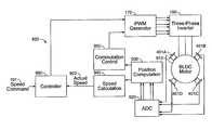
- FIG. 1is a block diagram of a three-phase BLDC motor controller with an optical transducer.
- three discrete Hall effect sensors located in the statorprovide rotor position feedback for commutation control.
- Each discrete Hall effect sensorprovides 180 degrees of position sensing coverage.
- Speed feedbackis provided by an incremental optical transducer (i.e., an optical transducer that detects incremental changes in rotor position without reference to an absolute rotor position).
- discrete Hall effect sensors 115 A-Care located in a circle around the spinning rotor, approximately 120 electrical degrees apart to provide full coverage position feedback of the rotor of BLDC motor 110 .
- the binary outputs of discrete Hall effect sensors 115 A, 115 B, and 115 Care connected to a decoder circuit 120 via communication lines 103 A, 103 B, and 103 C, respectively.
- each Hall effect sensorgoes high when the positive pole of a magnet attached to the rotor is aligned within the 180-degree arc centered on the given sensor. Because there are three sensors 120 degrees apart, there are roughly 60 degrees of sensor overlap, where the outputs of two sensors are high at the same time (actual region of overlap may depend on the distance between the sensors). Given the above arrangement of sensors, and representing the combined sensor outputs as a three-bit digital word, the possible three-bit values (i.e., states) assigned to rotor positioning are: (1 0 0), (1 1 0), (0 1 0), (0 1 1), (0 0 1) and (1 0 1). The state transitions occur at intervals of approximately 60 degrees. Decoder 120 extracts the six possible sensor combinations or states and feeds the discrete information to commutation control circuit 150 , which generates signals for energizing the appropriate stator coils within the motor.
- Commutation control 150provides a commutation signal to PWM generator 170 , which, in turn, uses pulse-width modulated signals to drive three-phase inverter block 180 .
- PWM generator 170uses pulse-width modulated signals to drive three-phase inverter block 180 .
- three-phase inverter block 180sources electrical current to one coil of the stator while sinking current through another coil. Due to the direction of the coil windings and the direction of current flow therein, one coil will attract the rotor while the other coil repels. The rotor is thus pulled (and pushed) in the desired direction.
- the duty cycles (i.e., the relative pulse-widths) of the signals from PWM generator 170determine how long the bursts of drive current last within the stator. By modulating the duty cycle based on the control signal received from control function 160 , a higher average drive current (or lower average), and a correspondingly stronger (or weaker) pull over time by the stator coils, may be achieved to implement acceleration and deceleration of the rotor.
- FIG. 2illustrates one example of a three-phase inverter coupled to a stator having three coils 200 A- 200 C.
- the coil arrangement shownis bipolar in nature, meaning that the coils share a single neutral node ( 209 ), such that when one coil is sourcing current, another coil must be sinking current. In this way, one coil will be attracting a first pole of a rotor magnet, and a second coil will be attracting the opposite pole of a rotor magnet and/or repelling the first pole. Unipolar arrangements may also be used, where each coil is driven independently, in only one direction.
- three-phase inverter 180is implemented with six transistors ( 201 A-B, 202 A-B and 203 A-B), represented in this example by FETs (field effect transistors). Though not shown, each FET may have a clamping diode coupled in parallel. FETs 201 A, 202 A and 203 A are shown as P-type transistors, though they may also be implemented with N-type transistors. The source nodes of FETs 201 A, 202 A and 203 A are commonly coupled to positive power supply node 204 . Similarly, the source nodes of FETs 201 B, 202 B and 203 B are commonly coupled to ground node or negative power supply node 205 .
- FETsfield effect transistors
- the drain nodes of FETs 201 A and 201 Bare commonly coupled to node 206 , which is further coupled to coil 200 A.
- the drain nodes of FETs 202 A and 202 Bare commonly coupled to node 207 , which is further coupled to coil 200 B.
- the drain nodes of FETs 203 A and 203 Bare commonly coupled to node 208 , which is further coupled to coil 200 C.
- Control signals A 1 , B 1 and C 1are coupled to the gates of FETs 201 A, 202 A and 203 A, respectively, and are responsible for determining when FETs 201 A, 202 A and 203 A will source current to coils 200 A, 200 B and 200 C, respectively.
- control signals A 2 , B 2 and C 2are coupled to the gates of FETs 201 B, 202 B and 203 B, respectively, and are responsible for determining when FETs 201 B, 202 B and 203 B will sink current from coils 200 A, 200 B and 200 C, respectively.
- the control loopdetermines the timing of control signals A 1 , A 2 , B 1 , B 2 , C 1 and C 2 , to pull (and optionally push) the rotor to achieve the desired rotation.
- an optical encoderis attached to BLDC motor 110 .
- the optical encoderincludes LED 104 , disk 105 and photo sensor 106 .
- the signal output of photo sensor 106is provided to timer 130 .
- Speed calculation circuit 140computes the rotor speed using information available from timer 130 . That information may include, for example, the timed interval between detection of consecutive notches or the number of notches detected within a fixed time interval.
- the computed speed 102is then compared with speed command 101 to generate a speed error, which is used within control function 160 to generate the modulation control signal for PWM generator 170 .
- Control function 160may be implemented with, for example, a PI (proportional-integral) controller or a PID (proportional-integral-derivative) controller.
- optical encoders and other speed transducersA disadvantage of optical encoders and other speed transducers is that the extra hardware of the encoder takes up space in the housing of the device and increases the overall weight of the device. Further, optical encoders are expensive. For larger devices, the increased size, weight and cost may not be important factors in the device design. However, in portable ventilator design, it is desirable that each ventilator unit be compact, lightweight, and affordable. Thus, the additional size, weight and cost of separate speed transducers make them undesirable as solutions for speed control in a portable ventilator.
- the inventionprovides a control system for a BLDC motor.
- An embodiment of the present inventioncontrols the airflow provided to a patient using a brushless DC (BLDC) motor to drive a Roots blower gas compressor. Coupling a Roots blower compressor with a BLDC motor provides a fully capable compressor in a small, cost-efficient package.
- the speed of the BLDC motor, and hence the air flow ratemay be precisely controlled using the outputs of analog Hall effect sensors to calculate angular position and speed for a speed control servo.
- analog sensorsare located within a BLDC motor assembly to provide continuous signals based on the magnetic flux sensed from a magnet attached to the rotor of the motor.
- sensor signalsmay be sampled at a sample rate that is independent of the angular speed of the rotor. Speed and position accuracy can therefore be maintained across the full range of rotor speeds.
- the sensor signalsare processed in a position function to obtain the rotor angular position.
- one possible position functionis the arctangent function.
- the arctangent functionmay be computed, for example, using an arithmetic computation, a small angle approximation, a polynomial evaluation approach, a table lookup approach, or a combination of various methods.
- the angular speedmay be derived by differentiating the angular position over time.
- FIG. 1is a block diagram of a BLDC motor controller with a separate optical encoder.
- FIG. 2is a circuit diagram of a three-phase inverter circuit driving a stator with three coils.
- FIG. 3is a block diagram of a compressor assembly in accordance with an embodiment of the present invention.
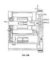
- FIG. 4is an illustration of a cross-sectional view of a motor/compressor system in accordance with an embodiment of the present invention.
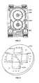
- FIG. 5is an illustration of an arrangement of the drive gears in a Roots blower compressor, in accordance with an embodiment of the present invention.
- FIG. 6is an illustration of an arrangement of analog Hall sensors on a PC board in accordance with an embodiment of the present invention.
- FIG. 7is a schematic diagram of a pressure control servo in accordance with an embodiment of the present invention.
- FIG. 8is an illustration of a flow-rate control servo in accordance with an embodiment of the present invention.
- FIG. 9is an illustration of a speed control servo in accordance with an embodiment of the present invention.
- FIGS. 10A and 10Billustrate the positioning of analog Hall sensors with respect to a BLDC rotor magnet to provide rotor position measurement, in accordance with an embodiment of the present invention.
- FIGS. 11A and 11Bare illustrations of sample analog sensor outputs during BLDC rotor rotation, in accordance with an embodiment of the present invention.
- FIG. 12is a flow diagram of a speed servo calibration process in accordance with an embodiment of the present invention.
- FIG. 13is a flow diagram of a position and speed computation process in accordance with an embodiment of the invention.
- the inventionprovides a control system for a brushless DC motor that can be used to drive a compressor in a portable mechanical ventilator.
- Mechanical ventilatorsare normally bulky machines used mostly in hospitals to assist patients who cannot breathe on their own. Recent advances in technology have resulted in a generation of portable generators that can be used outside the hospital. The current trend is to reduce the size and power consumption of mechanical ventilators while providing the full capability of full size hospital ventilator units.
- a mechanical ventilatorcreates positive intrapulmonary pressure to assist breathing. Positive intrapulmonary pressure is created by delivering gas to the patient's lungs so that positive pressure is created within the alveoli (i.e. the final branches of the respiratory tree that act as the primary gas exchange units of the lung).
- a mechanical ventilatoris essentially a device that generates a controlled flow of gas into a patient's airways during the inspiratory phase, and allows gas to flow out of the lungs during the exhalation phase. Mechanical ventilators use a gas compressor to generate the required airflow.
- the present inventioninvolves the precision speed control of an electric motor that may be used to drive a compressor in a mechanical ventilator.
- Mechanical ventilatorsmay have various modes of operation, e.g., pressure control and volume control.
- One common thread amongst most mechanical ventilatorsis that the desired operating mode is achieved by controlling the gas flow rate produced by the gas compressor.
- the motoris a brushless DC (BLDC) motor driving a Roots blower used as a compressor in a portable mechanical ventilator.
- the flow rate and pressure provided by the compressorare controlled by the speed of the BLDC motor.
- BLDCbrushless DC
- embodiments of the present inventionemploy analog sensors (e.g., analog Hall effect sensors, anisotropic magneto-resistive (AMR) sensors, etc.) to provide continuous rotor position and speed feedback for closed loop control.
- analog sensorse.g., analog Hall effect sensors, anisotropic magneto-resistive (AMR) sensors, etc.
- FIG. 3is a block diagram of a motor/compressor system in accordance with an embodiment of the present invention.
- the motor/compressor systemcomprises Roots blower 302 coupled to BLDC motor 304 .
- Gasi.e., air
- the air from inlet 308is compressed by Roots blower 302 , and then passed to the patient and/or other sections of the mechanical ventilator through outlet 310 .
- Fluid communication pathsare provided from the input of Roots blower 302 to solenoid valve 312 , and from the output of Roots blower 302 to solenoid valve 314 .
- Ambient air pressureis also channeled to solenoid valves 312 and 314 via ambient inlets 316 and 318 , respectively.
- the output fluid communication channels of solenoid valves 312 and 314are provided to blower differential pressure transducer 340 to convert the pressure differential between the two channels into an electrical signal representative of that pressure differential.
- transducer 340measures the difference between the output pressure and input pressure of Roots blower 302 .
- solenoid valves 312 and 314By controlling solenoid valves 312 and 314 , transducer 340 can also measure the pressure difference between the two ambient pressure inlets during an “auto-zero” phase of transducer 340 .
- Processor 320provides control of solenoid valves 312 and 314 , with solenoid drivers 322 transforming the digital control signals from processor 320 into power DC signals capable of driving the solenoid valves.
- Absolute pressure transducer 322 and temperature transducer 324generate electrical signals representing the absolute pressure level and the temperature.
- Each of transducers 322 , 324 and 340are coupled to transducer (XDCR) interface block 326 , which may provide signal amplification and filtering of the analog signals that are then provided to A/D (analog-to-digital) converter circuit 338 .
- A/D converter 338transforms the analog signals into digital values that may be processed by processor 320 .
- Processor 320also has the following associated circuitry: flash memory 348 , JTAG test circuitry 346 , random access memory (RAM) 344 , and UARTs (universal asynchronous receiver-transmitters) 342 and 336 .
- External JTAG connector 350is coupled to JTAG circuit 346 to facilitate hardware tests and debugging in accordance with the JTAG standard.
- Telemetry connector 352is coupled to UART 342 for the transmission of measured ventilator parameters to a remote system, e.g., for monitoring purposes.
- Communication and power connector 354is coupled to UART 336 for facilitating further external communication with the ventilator system, e.g., for operational testing and control.
- Connector 354also provides any necessary power signals to the motor/compressor system (e.g., 3.3, 5.0 and/or 15 VDC (volts DC)).
- Analog sensors 306are arranged on a PC board in a circular pattern perpendicular to the rotor shaft of BLDC motor 304 and adjacent to a two-pole magnet attached to the end of the rotor shaft. Analog sensors 306 provide measurements needed for computation of BLDC rotor position. The analog outputs of sensors 306 are passed through sensor interface 328 (e.g., for amplification and filtering), and then into A/D converter circuit 338 , where the analog sensor signals are converted into digital values for processing within processor 320 .
- sensor interface 328e.g., for amplification and filtering
- Processor 320executes software instructions to implement certain elements of the motor/compressor control loop, as will be described in detail later in this specification.
- Processor 320may be implemented, for example, with a general purpose processor or with a digital signal processor (DSP).
- DSPdigital signal processor
- Other embodimentsmay implement the functionality of processor 320 in firmware (e.g., instructions stored in an EPROM) or as equivalent logic in a hardware device (e.g., an ASIC (application specific integrated circuit) or an FPGA (field programmable gate array)).
- Processor 320receives the digitized sensor signals and pressure measurements via A/D converter block 338 (values may use RAM 344 for temporary storage), and determines an appropriate speed control value based upon the control process implemented (e.g., pressure control or volume control). Processor 320 also generates the appropriate commutation control signals given the current commutation state, and modulates the pulse widths of those commutation control signals based on the speed control value. The modulated commutation control signals are provided to three-phase inverter 330 .
- Three-phase inverter 330generates drive signals for the individual stator coils in BLDC motor 304 , as previously described.
- the systemmay also include a current limit circuit 334 coupled to three-phase inverter block 330 .
- FIG. 4is an illustration of a cross-sectional view of a motor/compressor system, in accordance with an embodiment of the present invention.
- the BLDC motor ( 400 ) end of the motor/compressor systemcomprises sensor PC board 410 , which provides support for a plurality of analog sensors 401 A-D (See FIG. 6 ); rotor shaft 416 ; rotor 402 ; magnet 412 attached at the BLDC end of rotor shaft 416 ; and stator 414 .
- the Roots blower endcomprises load bearings 418 and 422 , impellers 430 and 428 , shafts 416 and 426 , and gears 424 .
- the arrangement of gears 424at the end of rotor shaft 416 opposite BLDC motor 400 , is more clearly shown in FIG. 5 .
- the BLDC motor controllerenergizes stator 414 to cause rotor 402 to rotate.
- the rotation of rotor 402causes rotor shaft 416 to turn a first impeller 430 .
- Rotor shaft 416also drives gears 424 , which in turn drive shaft 426 and the second impeller 428 of the Roots blower.
- the operation of impellers 430 and 428draws air into the Roots blower through a port on one side of the motor/compressor system, and forces the air out a second opposing port at a desired pressure/flow rate.
- Magnet 412rotates at one end of shaft 416 , eliciting a sensor response from analog sensors 401 A-D, which is processed in the servo loops (not shown) of the BLDC motor controller to control the angular speed of rotor 402 .
- the Roots blowerprovides the appropriate gas flow rate to achieve positive pressure ventilation (positive intrapulmonary pressure) in a patient.
- gas flow produced by a mechanical ventilatoreither targets a desired volume with variable pressure, or controls the pressure while allowing the volume to vary.
- each ventilator modehas its own servo loop wrapped around an inner motor speed control loop. The various control modes are discussed below.
- processor 320implements the flow rate and speed control servos on PC board 410 , while the pressure control logic is implemented by a second ventilator processor that is external to the roots blower assembly, but in communication with processor 320 via a serial link.
- the pressure control modeinvolves controlling the inspiratory pressure for the duration of the inhalation cycle.
- the Roots bloweris required to provide a flow-rate to the patient to achieve a specific waveform or pressure profile.
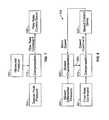
- a schematic diagram of the pressure control servo modeis shown in FIG. 7 .
- the desired pressure 701is compared against the actual pressure 703 developed in the patient's airway to generate an error, which is compensated in block 710 to generate a flow-rate command.
- the compensation in block 710may include circuits such as PID controllers (Proportional-Integral-Derivative Controllers) and pressure to flow rate conversion factors.
- the flow-rate commandis subsequently passed to the flow rate control servo 720 , which commands the Roots blower to generate the desired gas flow rate.
- the flow ratemay vary depending on how much gas is needed to satisfy the pressure requirement. The flow rate servo is discussed below.
- FIG. 8is an illustration of the flow-rate control servo in accordance with an embodiment of the present invention.
- the flow-rate command 801is compared against the actual flow rate 803 in compensation block 810 .
- the actual flow rate 803may be estimated by using the computed motor speed and measured blower differential pressure 240 in a blower characteristic function 830 .
- Characteristic function 830may be determined empirically, for example, by observing what the flow rate of the compressor is at known compressor speeds and differential pressures.
- the flow-rate erroris compensated in block 810 to generate a BLDC motor speed command.
- the compensation in block 810may include circuits incorporating any combination of proportional, integral, and derivative controllers (e.g., PI or PID controllers).
- the speed commandis subsequently passed to the speed servo 820 , which commands the Roots blower to generate the desired motor speed needed to satisfy the flow requirement.
- FIG. 9is an illustration of a speed control servo in accordance with an embodiment of the present invention.
- the speed control servocomprises controller 960 ; speed calculation module 940 ; commutation control circuit 950 ; position computation module 930 ; analog-to-digital converter (ADC) circuit 920 ; pulse-width modulation (PWM) generator circuit 170 ; three-phase inverter circuit 180 ; BLDC motor 910 ; and analog sensors 401 A-D.
- ADCanalog-to-digital converter
- PWMpulse-width modulation
- Controller block 960compares the desired motor speed (i.e. speed command 101 ) with the actual motor speed 902 to generate a speed error.
- the speed erroris appropriately compensated and integrated, if necessary, to generate a duty cycle command to PWM generator 170 .
- PWM generator 170generates modulated control signals, which three-phase inverter 180 uses to drive the stator coils of BLDC motor 910 .
- the commutation circuitis described herein with respect to a three-phase inverter, the present invention may be practiced with any commutation circuit incorporating any number of commutation phases, coils and/or rotor magnets.
- the BLDC rotor positionis measured using multiple analog sensors (e.g. analog Hall effect sensors or AMR sensors) 401 A-D.
- the analog sensorsproduce sine and cosine (quadrature) signals from which the rotor angular position may be derived.
- the outputs of the analog sensorsare converted to digital equivalents in ADC block 920 , and the digitized sine and cosine signals are used to compute rotor angular position in position computation block 930 .
- the sample rate of ADC block 920may be set to any value sufficiently high to provide proper commutation at the highest desired speed.
- the ADC sample ratemay be set independently of the angular speed of the rotor, and the sample rate can remain constant over the entire range of angular speeds.
- the computed angular positionis used to compute the actual rotor speed in block 940 , and used in commutation control block 950 to send commutation control signals to PWM generator 170 .
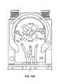
- FIG. 10Ais plane view of PC board 410 showing the radial positioning of the analog sensors 401 A- 401 D with respect to magnet 412 and the axis formed by rotor shaft 416 , in accordance with one embodiment of the invention.
- Magnet 412is shown centered on the rotor shaft axis. Magnet 412 may be located at the tip of the BLDC rotor, or at any other location in the BLDC assembly where the sensors can sense the magnetic flux.
- the radius of Magnet 412is represented in FIG. 10A by “R M ”.
- the four analog sensorsare positioned at an equal radial distance “R S ” from the central axis of shaft 416 , and offset from each other by approximately 90 degrees around that axis. The physical offset of 90 degrees provides for a corresponding phase offset of 90 degrees in the sensor sinusoidal outputs.
- FIG. 10Bis a side view of the BLDC motor and control portion of the blower assembly, showing the axial offset between analog sensors 401 A- 401 D and magnet 412 .
- Magnet 412is shown attached to the end of rotor shaft 416 and analog sensors 401 A- 401 D are attached to PC board 410 .
- the axial offset “Z” from the surface of each analog sensor to the surface of magnet 412is minimized to prevent weakening of sensor signal strength, while maintaining sufficient distance to avoid any contact or undesired friction effects due to hardware alignment deviations within prescribed design tolerances. In one embodiment, for example, Z is approximately 0.052 inches.
- the strength and characteristics of the outputs of the analog sensorsdepend on the radial distance (R S ) of the analog sensor relative to the radius (R M ) of magnet 412 , or more accurately, the absolute distance between the analog sensor and the surface of magnet 412 : (Z 2 +(R S ⁇ R M ) 2 ) 0.5 .
- Most analog sensorshave characteristics such that as R S approaches R M , the sensor signal strength gets stronger, but the signal quality becomes less ideal in terms of the shape of the output signals (e.g., the signals become more square in nature). The converse is also true, i.e., the shape of the sensor signal improves as R S increases relative to R M , but the signal strength diminishes.
- the optimal locationmay be determined experimentally.
- the radial distance R Smay be approximately 0.17 inches
- the radius R Mmay be approximately 0.09 inches, for example.
- embodiments of the inventionmay use any number of sensors adequate to provide analog position signals that may be used to calculate the rotor angular position. Providing pairs of opposing sensors (i.e., 180 degrees offset), however, and subtracting one opposing sensor's signal from the other can provide performance advantages, such as an improved signal-to-noise ratio. In embodiments where the sensors (or sensor pairs) are offset from each other by a known amount other than 90 degrees, the phase difference may be accounted for in the position calculation.
- the outputs of sensors 401 A and 401 Capproximate the sine and negative sine, respectively, of the rotor angular position.
- the outputs of sensors 401 B and 401 D(being approximately 90 degrees offset from the outputs of sensors 401 A and 401 C) approximate the cosine and negative cosine of the rotor angular position.
- sine and cosine signalsare obtained with approximately twice the amplitude of each sensor signal alone. Further, minor deviations in the sinusoidal profiles (e.g., due to unequal magnetic strength between the poles of the magnet, or slight misalignment of the magnet with respect to the center of the rotor shaft axis) may be diminished or canceled out by the combination of signals from opposing sensors.
- FIG. 11Ais an illustration of sample outputs of the four analog sensors of FIG. 10A while the BLDC rotor is rotating.
- signal waveform 1102represents the output of sensor 401 A
- signal waveform 1104represents the output of sensor 401 C
- Signal waveform 1108represents the output of sensor 401 B
- signal waveform 1106represents the output of sensor 401 D. If waveform 1104 is subtracted from waveform 1102 , the resultant is signal 1110 with characteristics of a sine function and twice the magnitude of either of signals 1104 and 1102 . Because the operation is differential, most electrical or common mode noise is eliminated. By the same token, subtracting waveform 1106 from waveform 1108 provides signal 1112 with characteristics of a cosine function and twice the magnitude of either of signals 1106 and 1108 .
- FIG. 11Billustrates how waveforms 1106 , 1108 and 1112 are altered under circumstances where magnet 412 is offset from the center of rotor shaft 416 by some small distance, such that the north pole of the magnet rotates closer to the analog sensors than the south pole.
- the positive portions of waveforms 1106 and 1108are boosted by the nearer rotation of the north pole.
- the negative portions of waveforms 1106 and 1108are affected in the opposite manner, showing a diminished magnitude.
- the zero crossings of both waveformsare shifted in position. Use of either sensor signal alone to determine angular position would yield erroneous results.
- waveform 1112the subtraction of waveform 1106 from 1108 yields a substantially sinusoidal result, correcting for the magnitude distortion and the zero crossing shifts.
- the actual rotor angular positionmay be obtained using various computational techniques.
- the angular positionmay be generated by computing an angular position function that corresponds to the arctangent of selected quotients of the sine and cosine signals.
- the arctangent functionmay be computed using an arithmetic computation, a small angle approximation, a polynomial evaluation approach, a table lookup approach, or a combination of various methods.
- the polynomial approachinvolves generating and storing coefficients for each signal in each quadrant.
- the coefficientsmay be generated in the laboratory by obtaining multiple measurements of the signals for known rotor angular positions in each quadrant, and then using a Least Squares Fit approximation to solve for the coefficients.
- coefficient determinationmay be performed as part of an initial device calibration process, as shown in the flow diagram of FIG. 12 .
- the statoris commutated to achieve a constant angular speed of the rotor in step 1200 .
- Thismay be done, for example, by using a simple counter to act as the angular position measurement of the rotor.
- the countermay be accelerated, while the drive current to the stator coils is ramped down from a large initial value to a smaller steady state value. This allows the rotor to synchronize with the stator and stabilize.
- readingsmay be obtained from the analog sensors in step 1201 .
- step 1202readings from opposing sensors are combined as previously described to provide sinusoidal waveforms 1110 and 1112 .
- the minimum and maximum values of waveforms 1110 and 1112may be measured and recorded, preferably but not necessarily over several rotations of the rotor. Those minimum and maximum values may then be used to determine any DC offsets in the sensor values that need to be compensated. Those DC offset values may be used to compensate the calibration sinusoidal waveform data, and may also be stored for use in compensating sensor waveform data during normal operation of the device.
- the commutation correction anglethat is, the angular offset between the position for the magnet and the simultaneous position of the rotor.
- the zero crossings of the sinusoidsmay be used to identify the commutation correction angle.
- a zero value from waveform 1110 combined with a positive value from waveform 1112indicates an angular position of zero degrees for magnet 412 .
- the corresponding commutation angle(determined from the counter) represents the commutation correction angle. This correction angle is needed due to small phase misalignments between the magnet and the rotor that may occur during manufacturing.
- step 1205sensor readings and the corresponding actual position values from the counter may be used to derive coefficients for each quadrant of rotation.
- the derived coefficientsare stored, indexed by quadrant, for use in computing position values during normal operation.
- Lis a vector of coefficients (e.g. three coefficients may be adequate if the polynomial equation used to compute the rotor angular position involves three elements: sine, cosine, and a bias), and H and Z are measured sensor and position data, respectively.
- Hmay be a matrix containing in each row, the sine (s), the cosine (c), and a constant (i.e. one) for each known angular rotor position.
- Zis a column vector containing each known angular rotor position (p).
- the H matrix and the Z vectormay be as illustrated below:
- H[ s 1 c 1 1 s 2 c 2 1 s 3 c 3 1 ⁇ ⁇ ⁇ s n c n 1 ]
- Z[ p 1 p 2 p 3 ⁇ ⁇ ⁇ p n ]
- the H matrix and Z vectorare populated with the measured sensor and position data, and then used to solve the Least Squares Fit equation above.
- the coefficients l 1 , l 2 , and l 3may be stored, indexed by quadrant, in memory, such as the flash memory of processor 320 .
- ⁇l 1 sin( ⁇ )+ l 2 cos( ⁇ )+ l 3
- sine( ⁇ ) and cosine( ⁇ )are the outputs from the respective sensor pairs.
- the coefficientsmay be determined such that the computed rotor angular position overlaps into the adjoining quadrants.
- the process of determining the least squares fitmay be performed, for example, in processor 320 , in a calibration application executing on another processor connected serially to processor 320 , or in both processor 320 and in a calibration application executing on another processor (external or internal).
- FIG. 13is a flow diagram of a position and speed computation process used during normal operation, in accordance with an embodiment of the invention.
- step 1300sensor readings are obtained for the current sample interval in accordance with a desired sample rate.
- step 1301those sensor readings are combined as previously described (i.e., by applying subtraction to readings of opposing sensors), and in step 1302 , DC correction (determined during the calibration process) may be applied to the combined readings.
- the current positionis derived from the sensor readings by identifying the current quadrant in step 1303 , and looking up the appropriate stored coefficients in step 1304 .
- the current quadrantmay be easily identified, in one embodiment, by analyzing the signs of the combined sensor readings. For example, when both readings are positive, the current quadrant is the first quadrant (i.e., zero to ninety degrees).
- step 1305the current coefficients and combined readings are used to solve the angular position equation and yield a computed position value.
- step 1306the commutation correction angle may be added to the computed position value to generate the actual position value for use in commutation control. If, during calibration, the correction angle was applied to the position values prior to deriving the quadrant coefficients, then the correction angle need not be re-applied during normal operation, because the correction angle is already accounted for within the derived coefficients.
- the angular speedis computed in step 1307 (which preferably occurs after step 1305 because the commutation correction angle is irrelevant to the speed computation) by taking the derivative of the computed position values, e.g., subtracting the stored position of the prior sample interval from the current position, and multiplying the result by the sampling frequency. Multiplying the position difference by the sampling frequency may be omitted if the speed command from the flow rate servo is normalized appropriately.
- the position and speed computation processbegins once more at step 1300 .
- a grid of possible angular position assignments to both sensor pair measurementsallows implementation of a look-up table for assigning the angular position measurement to the readings of the sensor signals.
- a readingmay be assigned or dismissed so that the update is omitted if the signals are outside the limits associated with acceptable angular positions.
- a table lookup embodimentmay automatically assign a predetermined angular position to each pair (sine and cosine) of valid coordinates or skip a position update when either of the sine and cosine data is not to be trusted.
- a table lookup to compute the phase angleallows for elimination of signals that cannot be trusted for accuracy and provides for sparse real-time computation of the quotients and inverse trigonometric functions (arctangent).
- the angular position computation processmay be done entirely in the analog domain.
- the ADC 920may not be required to convert the sensor outputs to digital form before computation of the arctangent.
- the arctangentmay be approximated for small angles by the tangent obtained from the analog division of the sine and the cosine signals.
- Such analog divisioncan be implemented by placing a multiplier in the feedback path of an analog multiplier device.
- the position and speed signalsmay also be filtered using some form of low-pass filter.
- some form of low-pass filterFor instance, an Infinite-Impulse Response (IIR) filter may be employed.
- IIRInfinite-Impulse Response
- An appropriate bandwidthwill depend on the sampling rate of the processor, how much delay is tolerable, and the electrical noise characteristics of the environment of the BLDC motor.
Landscapes
- Health & Medical Sciences (AREA)
- Engineering & Computer Science (AREA)
- Heart & Thoracic Surgery (AREA)
- Pulmonology (AREA)
- Anesthesiology (AREA)
- Biomedical Technology (AREA)
- Emergency Medicine (AREA)
- Hematology (AREA)
- Life Sciences & Earth Sciences (AREA)
- Animal Behavior & Ethology (AREA)
- General Health & Medical Sciences (AREA)
- Public Health (AREA)
- Veterinary Medicine (AREA)
- Power Engineering (AREA)
- Control Of Motors That Do Not Use Commutators (AREA)
Abstract
Description
L=(HTH)−1HTZ
Φ=l1sin(Φ)+l2cos(Φ)+l3
Claims (22)
Priority Applications (3)
| Application Number | Priority Date | Filing Date | Title |
|---|---|---|---|
| US10/847,693US7607437B2 (en) | 2003-08-04 | 2004-05-18 | Compressor control system and method for a portable ventilator |
| US11/877,117US8677995B2 (en) | 2003-08-04 | 2007-10-23 | Compressor control system for a portable ventilator |
| US11/877,168US20080092893A1 (en) | 2003-08-04 | 2007-10-23 | Compressor control system for a portable ventilator |
Applications Claiming Priority (3)
| Application Number | Priority Date | Filing Date | Title |
|---|---|---|---|
| US49242103P | 2003-08-04 | 2003-08-04 | |
| US10/847,693US7607437B2 (en) | 2003-08-04 | 2004-05-18 | Compressor control system and method for a portable ventilator |
| US11/877,117US8677995B2 (en) | 2003-08-04 | 2007-10-23 | Compressor control system for a portable ventilator |
Related Parent Applications (1)
| Application Number | Title | Priority Date | Filing Date |
|---|---|---|---|
| US10/847,693ContinuationUS7607437B2 (en) | 2003-08-04 | 2004-05-18 | Compressor control system and method for a portable ventilator |
Publications (2)
| Publication Number | Publication Date |
|---|---|
| US20080092892A1 US20080092892A1 (en) | 2008-04-24 |
| US8677995B2true US8677995B2 (en) | 2014-03-25 |
Family
ID=80318376
Family Applications (3)
| Application Number | Title | Priority Date | Filing Date |
|---|---|---|---|
| US10/847,693Active2027-06-15US7607437B2 (en) | 2003-08-04 | 2004-05-18 | Compressor control system and method for a portable ventilator |
| US11/877,117Active2026-05-21US8677995B2 (en) | 2003-08-04 | 2007-10-23 | Compressor control system for a portable ventilator |
| US11/877,168AbandonedUS20080092893A1 (en) | 2003-08-04 | 2007-10-23 | Compressor control system for a portable ventilator |
Family Applications Before (1)
| Application Number | Title | Priority Date | Filing Date |
|---|---|---|---|
| US10/847,693Active2027-06-15US7607437B2 (en) | 2003-08-04 | 2004-05-18 | Compressor control system and method for a portable ventilator |
Family Applications After (1)
| Application Number | Title | Priority Date | Filing Date |
|---|---|---|---|
| US11/877,168AbandonedUS20080092893A1 (en) | 2003-08-04 | 2007-10-23 | Compressor control system for a portable ventilator |
Country Status (1)
| Country | Link |
|---|---|
| US (3) | US7607437B2 (en) |
Cited By (4)
| Publication number | Priority date | Publication date | Assignee | Title |
|---|---|---|---|---|
| US20120138051A1 (en)* | 2009-08-11 | 2012-06-07 | Curran Desmond T | Method of Controlling a Powered Air Purifying Respirator |
| US20150180391A1 (en)* | 2013-12-20 | 2015-06-25 | Semiconductor Components Industries, Llc | Motor control circuit and method |
| US20190181780A1 (en)* | 2017-12-07 | 2019-06-13 | Hyundai Motor Company | Motor control method |
| US10905836B2 (en) | 2015-04-02 | 2021-02-02 | Hill-Rom Services Pte. Ltd. | Manifold for respiratory device |
Families Citing this family (54)
| Publication number | Priority date | Publication date | Assignee | Title |
|---|---|---|---|---|
| US7607437B2 (en)* | 2003-08-04 | 2009-10-27 | Cardinal Health 203, Inc. | Compressor control system and method for a portable ventilator |
| AU2006220222A1 (en) | 2005-03-01 | 2006-09-08 | Resmed Limited | Recognition system for an apparatus that delivers breathable gas to a patient |
| ES2414869T3 (en)* | 2005-03-08 | 2013-07-23 | Activaero Gmbh | Inhalation device |
| US8985105B2 (en)* | 2005-10-21 | 2015-03-24 | Compumedics Medical Innovation Pty Ltd | Apparatus for delivery of pressurised gas |
| US7482770B2 (en)* | 2005-11-30 | 2009-01-27 | Regal-Beloit Corporation | Methods and systems for providing PWM control signals to an electronically commutated motor |
| US7913689B2 (en)* | 2005-12-21 | 2011-03-29 | Resmed Limited | Identification system and method for mask and ventilator components |
| US7369757B2 (en)* | 2006-05-24 | 2008-05-06 | Nellcor Puritan Bennett Incorporated | Systems and methods for regulating power in a medical device |
| US7443119B2 (en)* | 2007-03-07 | 2008-10-28 | Green Mark Technology Inc. | Circuit and method for controlling the rotating speed of a BLDC motor |
| EP1981155A2 (en)* | 2007-04-09 | 2008-10-15 | Seiko Epson Corporation | Brushless motor |
| JP5553967B2 (en) | 2007-04-13 | 2014-07-23 | レスメド・リミテッド | Method and system for motor fault detection |
| US20080257348A1 (en)* | 2007-04-20 | 2008-10-23 | Piper S David | Emergency and mass casualty ventilator |
| US8193748B2 (en)* | 2008-10-10 | 2012-06-05 | Smi Holdings, Inc. | Integrated brushless DC motor and controller |
| US8294396B2 (en)* | 2009-07-13 | 2012-10-23 | Hamilton Sundstrand Space Systems International, Inc. | Compact FPGA-based digital motor controller |
| WO2011054074A1 (en)* | 2009-11-06 | 2011-05-12 | Bosch Security Systems Bv | Brushless motor speed control system |
| US20110114093A1 (en)* | 2009-11-16 | 2011-05-19 | Honeywell International Inc. | Automatic fitment detection and flow calibration using non-contact sensing in powered air purifying respirators |
| EP2335755A1 (en) | 2009-12-17 | 2011-06-22 | Sanofi-Aventis Deutschland GmbH | Device and method for delivery of two or more drug agents |
| WO2011120012A2 (en)* | 2010-03-25 | 2011-09-29 | Carmichael, Robert, Manuel | Air on demand breathing system using a dynamic transducer for controlling air |
| CN102822637B (en)* | 2010-04-02 | 2015-03-04 | 株式会社安川电机 | Signal processing devices, encoders and motor systems |
| US20120060290A1 (en)* | 2010-09-09 | 2012-03-15 | Midmark Corporation | Brushless dc motor braking for a barrier free medical table |
| US8897954B2 (en)* | 2011-05-05 | 2014-11-25 | Deere & Company | Method for calibrating position sensor on electric motor |
| TWI604179B (en)* | 2012-05-30 | 2017-11-01 | 尼康股份有限公司 | Encoder and drive device |
| DE102012211356A1 (en)* | 2012-06-29 | 2014-01-02 | Robert Bosch Gmbh | Method for operating an electric motor device and corresponding electric motor device |
| EP2931340B1 (en) | 2012-12-13 | 2020-08-12 | Koninklijke Philips N.V. | Handheld pressure support system for treating hyperinflation |
| CN103908726A (en)* | 2012-12-29 | 2014-07-09 | 北京谊安医疗系统股份有限公司 | Electric control breathing machine or anesthesia machine active exhalation valve based automatic calibration method |
| CN103353136B (en)* | 2013-07-02 | 2015-09-09 | 德意电器股份有限公司 | A kind of there is air quantity regulatory function range hood and control system and control method |
| US9724017B2 (en)* | 2013-07-03 | 2017-08-08 | Breathe Technologies, Inc. | Respiratory cycle patient ventilation flow limitation detection |
| US9164497B2 (en)* | 2013-10-01 | 2015-10-20 | The Boeing Company | Reluctance motor system |
| US9239345B2 (en) | 2013-11-20 | 2016-01-19 | Woodward, Inc. | Controlling a motor with two or more Hall sensors |
| JP6277001B2 (en)* | 2014-01-22 | 2018-02-07 | 株式会社ミツトヨ | Drive control device, drive device, and drive control method |
| EP3029826B1 (en)* | 2014-12-05 | 2018-04-04 | Etel S. A.. | Method for determining a commutation angle |
| US10164501B2 (en) | 2014-12-11 | 2018-12-25 | The Boeing Company | Reluctance motor with dual-pole rotor system |
| US9929623B2 (en) | 2014-12-11 | 2018-03-27 | The Boeing Company | Reluctance motor with virtual rotor |
| JP2016123237A (en)* | 2014-12-25 | 2016-07-07 | 株式会社ジェイテクト | Motor unit |
| US10245406B2 (en) | 2015-03-24 | 2019-04-02 | Ventec Life Systems, Inc. | Ventilator with integrated oxygen production |
| US11247015B2 (en) | 2015-03-24 | 2022-02-15 | Ventec Life Systems, Inc. | Ventilator with integrated oxygen production |
| WO2017019569A1 (en)* | 2015-07-24 | 2017-02-02 | Cepheid | Molecular diagnostic assay system |
| CN108348714B (en)* | 2015-09-29 | 2020-11-17 | 皇家飞利浦有限公司 | Method of pressure and gas mixture control for non-invasive ventilation |
| KR102251270B1 (en) | 2016-01-05 | 2021-05-11 | 밀워키 일렉트릭 툴 코포레이션 | Vibration reduction system and method for power tools |
| CN108778651B (en) | 2016-02-03 | 2021-06-18 | 米沃奇电动工具公司 | System and method for configuring a reciprocating saw |
| US11529478B2 (en) | 2016-02-22 | 2022-12-20 | Advanced Bio Machines Pte. Ltd. | Oscillatory respiratory care apparatus |
| US20170361041A1 (en)* | 2016-06-16 | 2017-12-21 | Loewenstein Medical Technology S.A. | Respirator for apap respiration using oscillatory pressure |
| US10773049B2 (en) | 2016-06-21 | 2020-09-15 | Ventec Life Systems, Inc. | Cough-assist systems with humidifier bypass |
| US10884012B1 (en) | 2016-12-06 | 2021-01-05 | United States Of America As Represented By The Administrator Of The National Aeronautics And Space Administration | Velocity determination system and method |
| US10960922B2 (en)* | 2017-01-31 | 2021-03-30 | Steering Solutions Ip Holding Corporation | Fault tolerant field oriented control for electric power steering |
| US10668822B2 (en)* | 2017-07-25 | 2020-06-02 | GM Global Technology Operations LLC | Elimination of fundamental harmonic position measurement errors in a vector-based position sensing system |
| GB2566292B (en)* | 2017-09-07 | 2020-03-04 | Delphi Automotive Systems Lux | Method of controlling a brushless DC motor |
| WO2019221852A1 (en) | 2018-05-13 | 2019-11-21 | Ahmad Samir Saleh | Portable medical ventilator system using portable oxygen concentrators |
| JP2020074970A (en)* | 2018-11-08 | 2020-05-21 | セイコーインスツル株式会社 | CPAP system and CPAP device |
| EP3763408A3 (en)* | 2019-06-21 | 2021-03-24 | Seiko Instruments Inc. | Cpap system and cpap apparatus |
| JP2021000423A (en)* | 2019-06-21 | 2021-01-07 | セイコーインスツル株式会社 | CPAP system and CPAP device |
| CN114450053A (en) | 2019-09-10 | 2022-05-06 | 费雪派克医疗保健有限公司 | Methods and systems for controlling oxygen delivery in flow therapy devices |
| US12140359B2 (en) | 2021-10-21 | 2024-11-12 | Copeland Lp | Climate control systems for use with high glide working fluids and methods for operation thereof |
| US12320569B2 (en) | 2022-11-17 | 2025-06-03 | Copeland Lp | Climate control systems having ejector cooling for use with moderate to high glide working fluids and methods for operation thereof |
| CN116020031B (en)* | 2023-03-27 | 2023-06-27 | 广州国家实验室 | Constant volume control method, system and device for breathing machine and storage medium |
Citations (257)
| Publication number | Priority date | Publication date | Assignee | Title |
|---|---|---|---|---|
| US56611A (en) | 1866-07-24 | Improved mode of manufacturing harness-nails | ||
| US56614A (en) | 1866-07-24 | Improvement in cross-heads for blowers | ||
| US587907A (en) | 1897-08-10 | Piston for rotary pumps | ||
| US1769153A (en) | 1928-03-07 | 1930-07-01 | Meyer William Warren | Rotary blower or pump |
| US2014932A (en) | 1933-03-17 | 1935-09-17 | Gen Motors Corp | Roots blower |
| US2787999A (en) | 1951-09-13 | 1957-04-09 | Bennett Vivian Ray | Respiratory ventilation meter |
| US3089638A (en) | 1958-12-01 | 1963-05-14 | Dresser Ind | Impellers for fluid handling apparatus of the rotary positive displacement type |
| US3094274A (en) | 1960-04-29 | 1963-06-18 | Harris A Thompson | Artificial respirator apparatus |
| US3371856A (en) | 1966-03-24 | 1968-03-05 | Fuller Co | Modified cycloidal impeller |
| US3459395A (en) | 1967-08-16 | 1969-08-05 | Ambac Ind | Shock isolating means |
| US3658443A (en) | 1969-11-21 | 1972-04-25 | Giovanni Fumagalli | Pressure alternating device for automatic lungs ventilator actuation |
| US3865523A (en) | 1973-03-16 | 1975-02-11 | Samuel J Baehr | Continuous flow rotary pump |
| GB1387841A (en) | 1972-02-15 | 1975-03-19 | Blease Medical Equipment Ltd | Fluid control valve |
| US3905362A (en) | 1973-10-02 | 1975-09-16 | Chemetron Corp | Volume-rate respirator system and method |
| US3916888A (en) | 1973-10-04 | 1975-11-04 | Tecna Corp | Respirator |
| US3941206A (en) | 1974-05-08 | 1976-03-02 | Burgess Industries Incorporated | Noise attenuating snubber |
| GB1447091A (en) | 1973-09-13 | 1976-08-25 | Philips Electronic Associated | Respiratory systems |
| US4080103A (en) | 1977-01-12 | 1978-03-21 | Bird F M | Portable air compressor system for respirator |
| US4096858A (en) | 1975-01-29 | 1978-06-27 | Chemetron Corporation | Volume-rate respirator system and method |
| US4121578A (en) | 1976-10-04 | 1978-10-24 | The Bendix Corporation | Physiological responsive control for an oxygen regulator |
| US4182599A (en) | 1973-10-02 | 1980-01-08 | Chemetron Corporation | Volume-rate respirator system and method |
| US4215977A (en) | 1977-11-14 | 1980-08-05 | Calspan Corporation | Pulse-free blower |
| US4220219A (en) | 1978-09-14 | 1980-09-02 | Flugger Ray T | Lightweight muffler and method for muffling noise |
| US4227869A (en) | 1976-10-19 | 1980-10-14 | Atlas Copco Aktiebolag | Intermeshing pump rotor gears with involute and linear flank portions |
| US4239039A (en) | 1979-02-28 | 1980-12-16 | Thompson Harris A | Dual control valve for positive pressure artificial respiration apparatus |
| US4248194A (en) | 1979-08-23 | 1981-02-03 | Trw Inc. | Method and apparatus for controlling the operation of a pump |
| US4257453A (en) | 1979-04-06 | 1981-03-24 | Ruth L. Hesse | Peep valve with improved vibration damping |
| US4267899A (en) | 1979-08-31 | 1981-05-19 | Donaldson Company, Inc. | Muffler assembly |
| US4323064A (en) | 1976-10-26 | 1982-04-06 | Puritan-Bennett Corporation | Volume ventilator |
| US4448192A (en) | 1982-03-05 | 1984-05-15 | Hewlett Packard Company | Medical ventilator device parametrically controlled for patient ventilation |
| US4455132A (en) | 1982-02-23 | 1984-06-19 | Fiat Auto S.P.A. | Volumetric compressor of the roots type |
| US4495947A (en) | 1982-09-23 | 1985-01-29 | Imasco-Cdc Research Foundation | High speed medical ventilator |
| US4564345A (en) | 1984-09-04 | 1986-01-14 | Eaton Corporation | Supercharger with reduced noise |
| US4595349A (en) | 1983-06-20 | 1986-06-17 | Eaton Corp. | Supercharger rotor, shaft, and gear arrangement |
| DE3238015C2 (en) | 1982-10-13 | 1986-07-31 | Aerzener Maschinenfabrik Gmbh, 3251 Aerzen | Roots compressor |
| US4609335A (en) | 1984-09-20 | 1986-09-02 | Eaton Corporation | Supercharger with reduced noise and improved efficiency |
| US4637439A (en) | 1981-02-09 | 1987-01-20 | Cadbury Schweppes, Plc | Mini-regulator valve assembly |
| US4656553A (en) | 1986-01-21 | 1987-04-07 | Comair Rotron, Inc. | Electronically programmable universal brushless DC fan with integral tracking and locked rotor protection |
| US4666384A (en) | 1983-09-30 | 1987-05-19 | Aisin Seiki Kabushiki Kaisha | Roots type blower with reduced gaps between the rotors |
| US4673058A (en) | 1986-05-09 | 1987-06-16 | G Enterprises Limited | High performance automotive muffler |
| US4684330A (en) | 1980-08-28 | 1987-08-04 | Stal Refrigeration Ab | Drive for rotary compressor |
| US4686999A (en) | 1985-04-10 | 1987-08-18 | Tri Fund Research Corporation | Multi-channel ventilation monitor and method |
| US4702240A (en) | 1986-07-22 | 1987-10-27 | Bear Medical Systems, Inc. | Demand-responsive gas blending system for medical ventilator |
| DE3620792A1 (en) | 1986-06-20 | 1987-12-23 | Wankel Gmbh | EXTERNAL ROTATION PISTON BLOWER |
| US4747403A (en) | 1986-01-27 | 1988-05-31 | Advanced Pulmonary Technologies, Inc. | Multi-frequency jet ventilation technique and apparatus |
| GB2157370B (en) | 1984-04-13 | 1988-08-17 | Aerzener Maschf Gmbh | Roots compressor for compressing of gaseous media |
| US4768934A (en) | 1985-11-18 | 1988-09-06 | Eaton Corporation | Port arrangement for rotary positive displacement blower |
| US4794922A (en) | 1986-11-04 | 1989-01-03 | Bird Products Corporation | Ventilator manifold |
| DE3414064C2 (en) | 1982-10-13 | 1989-03-23 | Aerzener Maschinenfabrik Gmbh, 3258 Aerzen, De | |
| US4838257A (en) | 1987-07-17 | 1989-06-13 | Hatch Guy M | Ventilator |
| US4844044A (en) | 1988-06-27 | 1989-07-04 | Eaton Corporation | Torsion damping mechanism for a supercharger |
| US4846302A (en) | 1986-08-08 | 1989-07-11 | Tenneco Inc. | Acoustic muffler |
| US4867151A (en) | 1987-10-19 | 1989-09-19 | Bird F M | Mobile self-contained ventilator |
| US4897583A (en)* | 1989-03-07 | 1990-01-30 | Sundstrand Corporation | Variable speed variable torque brushless DC motor |
| US4905685A (en) | 1987-04-14 | 1990-03-06 | Siemens Aktiengesellschaft | Inhalation anaesthesia equipment |
| US4938670A (en) | 1989-10-02 | 1990-07-03 | Tocew Lee | Rotary fluid machine |
| US4957107A (en) | 1988-05-10 | 1990-09-18 | Sipin Anatole J | Gas delivery means |
| US4975032A (en) | 1987-07-07 | 1990-12-04 | Fuji Jukogyo Kabushiki Kaisha | Roots type blower having reduced gap between rotors for increasing efficiency |
| US5040959A (en) | 1989-02-17 | 1991-08-20 | Fuji Jukogyo Kabushiki Kaisha | Roots blower with improved clearance between rotors |
| US5056995A (en) | 1989-02-28 | 1991-10-15 | Aisin Seiki Kabushiki Kaisha | Displacement compressor with reduced compressor noise |
| US5127400A (en) | 1990-03-23 | 1992-07-07 | Bird Products Corp. | Ventilator exhalation valve |
| US5131829A (en) | 1991-06-19 | 1992-07-21 | Eaton Corporation | Trapped volume vent means for meshing lobes of roots-type supercharger |
| US5145349A (en) | 1991-04-12 | 1992-09-08 | Dana Corporation | Gear pump with pressure balancing structure |
| US5152684A (en) | 1990-08-27 | 1992-10-06 | Leybold Aktiengesellschaft | Rotor profile for a roots vacuum pump |
| US5161525A (en) | 1990-05-11 | 1992-11-10 | Puritan-Bennett Corporation | System and method for flow triggering of pressure supported ventilation |
| EP0239026B1 (en) | 1986-03-24 | 1993-05-12 | Performance Controls, Inc. | Method and apparatus for determining shaft position and for providing commutation signals |
| US5211170A (en) | 1991-04-01 | 1993-05-18 | Press Roman J | Portable emergency respirator |
| US5222148A (en) | 1992-04-29 | 1993-06-22 | General Motors Corporation | Active noise control system for attenuating engine generated noise |
| US5237987A (en) | 1990-06-07 | 1993-08-24 | Infrasonics, Inc. | Human lung ventilator system |
| US5239994A (en) | 1991-05-10 | 1993-08-31 | Bunnell Incorporated | Jet ventilator system |
| US5253486A (en) | 1990-05-01 | 1993-10-19 | Masanori Sugahara | Silencer attenuating a noise from a noise source to be ventilated and a method for active control of its noise attenuation system |
| US5335651A (en) | 1990-05-16 | 1994-08-09 | Hill-Rom Company, Inc. | Ventilator and care cart each capable of nesting within and docking with a hospital bed base |
| US5350888A (en) | 1992-05-01 | 1994-09-27 | Tennessee Gas Pipeline Company | Broad band low frequency passive muffler |
| US5384527A (en)* | 1993-05-12 | 1995-01-24 | Sundstrand Corporation | Rotor position detector with back EMF voltage estimation |
| US5388575A (en) | 1992-09-25 | 1995-02-14 | Taube; John C. | Adaptive controller for automatic ventilators |
| US5398676A (en) | 1993-09-30 | 1995-03-21 | Press; Roman J. | Portable emergency respirator |
| US5428276A (en)* | 1992-09-23 | 1995-06-27 | Sgs-Thomson Microelectronics, Inc. | Automatic adjustment of commutation delay for brushless DC motor for improved efficiency |
| US5430362A (en)* | 1993-05-12 | 1995-07-04 | Sundstrand Corporation | Engine starting system utilizing multiple controlled acceleration rates |
| US5439358A (en) | 1994-01-27 | 1995-08-08 | Weinbrecht; John F. | Recirculating rotary gas compressor |
| US5461293A (en)* | 1993-05-12 | 1995-10-24 | Sundstrand Corporation | Rotor position detector |
| US5493200A (en)* | 1993-05-12 | 1996-02-20 | Sundstrand Corporation | Control for a brushless generator |
| US5493892A (en) | 1993-04-01 | 1996-02-27 | Ford Motor Company | Method for calibrating the time response of a mass air flow sensor by laser trimming selected resistors and without an air flow |
| US5495163A (en)* | 1993-05-12 | 1996-02-27 | Sundstrand Corporation | Control for a brushless generator operable in generating and starting modes |
| US5495162A (en)* | 1993-05-12 | 1996-02-27 | Sundstrand Corporation | Position-and-velocity sensorless control for starter generator electrical system using generator back-EMF voltage |
| EP0521709B1 (en) | 1991-07-01 | 1996-05-08 | Kabushiki Kaisha Toshiba | Power converting device with inverter circuitry for driving multiple-phase variable-speed motor |
| US5542416A (en) | 1994-01-12 | 1996-08-06 | Societe D'applications Industrielles Medicales Et Electroniques (Saime) | Apparatus for assisting ventilation including reduced exhalation pressure mode |
| US5577152A (en) | 1995-04-12 | 1996-11-19 | Chen; Ruey-Zon | Motor assembly |
| US5582163A (en) | 1993-12-06 | 1996-12-10 | Intermed Equipamento Medico Hospitalar Ltda. | Respiratory control system and apparatus |
| US5632270A (en) | 1994-09-12 | 1997-05-27 | Puritan-Bennett Corporation | Method and apparatus for control of lung ventilator exhalation circuit |
| US5638600A (en) | 1994-10-07 | 1997-06-17 | Ford Motor Company | Method of making an efficiency enhanced fluid pump or compressor |
| US5664563A (en) | 1994-12-09 | 1997-09-09 | Cardiopulmonary Corporation | Pneumatic system |
| US5687717A (en) | 1996-08-06 | 1997-11-18 | Tremont Medical, Inc. | Patient monitoring system with chassis mounted or remotely operable modules and portable computer |
| US5694926A (en) | 1994-10-14 | 1997-12-09 | Bird Products Corporation | Portable drag compressor powered mechanical ventilator |
| US5702240A (en) | 1995-05-05 | 1997-12-30 | Tuthill Corporation | Rotary positive displacement blower having a diverging outlet part |
| US5701883A (en) | 1996-09-03 | 1997-12-30 | Respironics, Inc. | Oxygen mixing in a blower-based ventilator |
| US5720276A (en) | 1994-10-25 | 1998-02-24 | Teijin Limited | Apparatus for supplying a respiratory gas to a patient |
| US5760348A (en) | 1994-04-28 | 1998-06-02 | Heuser; Stephen Glen | Noise attenuating apparatus |
| US5763792A (en) | 1996-05-03 | 1998-06-09 | Dragerwerk Ag | Respiratory flow sensor |
| US5783782A (en) | 1996-10-29 | 1998-07-21 | Tenneco Automotive Inc. | Multi-chamber muffler with selective sound absorbent material placement |
| US5799652A (en) | 1995-05-22 | 1998-09-01 | Hypoxico Inc. | Hypoxic room system and equipment for Hypoxic training and therapy at standard atmospheric pressure |
| US5823186A (en) | 1996-06-20 | 1998-10-20 | Dragerwerk Ag | Respirator |
| US5831223A (en) | 1997-09-24 | 1998-11-03 | Kesselring; Stephen H. | Self-tuning exhaust muffler |
| US5871465A (en) | 1994-11-25 | 1999-02-16 | I-Flow Corporation | Remotely programmable infusion system |
| US5880586A (en) | 1994-11-22 | 1999-03-09 | Robert Bosch Gmbh | Apparatus for determining rotational position of a rotatable element without contacting it |
| US5918597A (en) | 1998-01-15 | 1999-07-06 | Nellcor Puritan Bennett | Peep control in a piston ventilator |
| US5931159A (en) | 1995-09-09 | 1999-08-03 | Origin Medical Instrument Co., Ltd. | Lung ventilator |
| US5934274A (en) | 1995-02-08 | 1999-08-10 | Puritan-Bennett Corporation | Gas mixing apparatus for a ventilator |
| US5944501A (en) | 1996-06-28 | 1999-08-31 | Anlet Co., Ltd. | Roots blower having zigzag meandering grooves in the casing inner wall surface |
| EP0938909A1 (en) | 1997-12-15 | 1999-09-01 | Siemens-Elema AB | Ventilator system |
| DE19817356A1 (en) | 1998-04-18 | 1999-10-21 | Bosch Gmbh Robert | Angle indicator for determining an angle between a sensor arrangement and a magnetic field |
| US5996731A (en) | 1998-02-24 | 1999-12-07 | Czabala; Michael P. | Compressor muffler |
| US6009871A (en) | 1996-11-14 | 2000-01-04 | Dragerwek Aktiengesellschaft | Ventilating apparatus |
| US6065944A (en) | 1997-09-12 | 2000-05-23 | Cobb; Ronald F. | Annular pump |
| US6070576A (en) | 1998-06-02 | 2000-06-06 | Advanced Technology Materials, Inc. | Adsorbent-based storage and dispensing system |
| US6076523A (en) | 1998-01-15 | 2000-06-20 | Nellcor Puritan Bennett | Oxygen blending in a piston ventilator |
| US6099277A (en) | 1998-08-12 | 2000-08-08 | Dresser Industries, Inc. | Gas blower and method utilizing recirculation openings |
| US6102038A (en) | 1998-05-15 | 2000-08-15 | Pulmonetic Systems, Inc. | Exhalation valve for mechanical ventilator |
| US6125844A (en) | 1998-04-30 | 2000-10-03 | Westwood Biomedical | Portable oxygen based drug delivery system |
| US6152135A (en) | 1998-10-23 | 2000-11-28 | Pulmonetic Systems, Inc. | Ventilator system |
| US6152129A (en) | 1996-08-14 | 2000-11-28 | Resmed Limited | Determination of leak and respiratory airflow |
| US6155257A (en) | 1998-10-07 | 2000-12-05 | Cprx Llc | Cardiopulmonary resuscitation ventilator and methods |
| US6158434A (en) | 1996-02-27 | 2000-12-12 | Henk W. Koster | Ventilatory system with additional gas administrator |
| US6164412A (en) | 1998-04-03 | 2000-12-26 | Arvin Industries, Inc. | Muffler |
| US6176693B1 (en) | 1997-03-17 | 2001-01-23 | Finder Pompe S.P.A. | Volumetric blower with covers having a duct for connection to the delivery manifold |
| JP2001050774A (en) | 1999-08-06 | 2001-02-23 | Tamagawa Seiki Co Ltd | Sine cosine output sensor and servo motor using the same |
| US6237592B1 (en)* | 1995-07-03 | 2001-05-29 | Resmed Limited | Auto-calibration of pressure transducer offset |
| US6239564B1 (en) | 1998-10-06 | 2001-05-29 | H.R. Textron, Inc. | State advance controller commutation loop for brushless D.C. motors |
| US6247906B1 (en) | 1999-05-28 | 2001-06-19 | Joseph M. Pijanowski | Combined pump and motor device |
| US6279574B1 (en) | 1998-12-04 | 2001-08-28 | Bunnell, Incorporated | Variable flow and pressure ventilation system |
| US6279576B1 (en) | 1996-11-18 | 2001-08-28 | Louis Gibeck, Ab | Purification system |
| US6283246B1 (en) | 1998-07-16 | 2001-09-04 | Betech Co., Ltd. | Silencer |
| US6305372B1 (en) | 1995-04-07 | 2001-10-23 | John L. Servidio | Pressure support ventilatory assist system |
| US20010044588A1 (en) | 1996-02-22 | 2001-11-22 | Mault James R. | Monitoring system |
| US6349724B1 (en) | 2000-07-05 | 2002-02-26 | Compumedics Sleep Pty. Ltd. | Dual-pressure blower for positive air pressure device |
| US6354558B1 (en) | 1998-11-20 | 2002-03-12 | Carrier Corporation | Compressor mounting |
| EP1243282A1 (en) | 2001-03-21 | 2002-09-25 | Airox | Ventilator |
| US20020134378A1 (en) | 2001-03-26 | 2002-09-26 | Finnegan Linda A. | Sound dampening housing for respiratory assist devices |
| US6468222B1 (en) | 1999-08-02 | 2002-10-22 | Healthetech, Inc. | Metabolic calorimeter employing respiratory gas analysis |
| US6474960B1 (en) | 2000-03-21 | 2002-11-05 | DRäGER MEDIZINTECHNIK GMBH | Respirator radial compressor with reduced sound emission |
| US6484719B1 (en) | 1996-09-23 | 2002-11-26 | Resmed, Inc. | Method for providing ventilatory assistance in a spontaneously breathing subject |
| US20030024529A1 (en) | 2000-04-03 | 2003-02-06 | Safety Equipment Sweden Ab | Ventilation system for a protective suit |
| US20030057904A1 (en) | 2001-08-22 | 2003-03-27 | Sacher Ing. Manfred | Process and device for feedback-controlling rotary machines |
| US6543449B1 (en) | 1997-09-19 | 2003-04-08 | Respironics, Inc. | Medical ventilator |
| JP2003124986A (en) | 2001-10-18 | 2003-04-25 | Fujitsu Ltd | VPN service management system, VPN service manager and VPN service agent |
| US6558137B2 (en) | 2000-12-01 | 2003-05-06 | Tecumseh Products Company | Reciprocating piston compressor having improved noise attenuation |
| US6564798B1 (en) | 1999-07-15 | 2003-05-20 | Siemens Elema Ab | Method and computer software product for controlling an expiratory valve in a ventilator |
| US6571792B1 (en) | 1997-10-15 | 2003-06-03 | Datex-Ohmeda, Inc. | Smart modular anesthesia respiratory system |
| US6571796B2 (en) | 2001-02-08 | 2003-06-03 | University Of Florida | Tracheal pressure ventilation respiratory system |
| US6591835B1 (en) | 1997-09-26 | 2003-07-15 | Airon Corporation | Pneumatically controlled multifunction medical ventilator |
| US6615831B1 (en) | 1999-07-02 | 2003-09-09 | Respironics, Inc. | Pressure support system and method and a pressure control valve for use in such system and method |
| US6615446B2 (en) | 2001-11-30 | 2003-09-09 | Mary Ellen Noreen | Canister vacuum cleaner |
| US6619325B2 (en) | 2001-12-04 | 2003-09-16 | The United States Of America As Represented By The Administrator Of The U.S. Environmental Protection Agency | Hydraulic hybrid accumulator shut-off valve |
| US6619286B2 (en) | 2000-06-16 | 2003-09-16 | 3M Innovative Properties Company | Pressure regulator for a respirator system |
| US6626175B2 (en) | 2000-10-06 | 2003-09-30 | Respironics, Inc. | Medical ventilator triggering and cycling method and mechanism |
| US6629934B2 (en) | 2000-02-02 | 2003-10-07 | Healthetech, Inc. | Indirect calorimeter for medical applications |
| US6629525B2 (en) | 2000-08-03 | 2003-10-07 | Sequal Technologies, Inc. | Portable oxygen concentration system and method of using the same |
| US6629531B2 (en) | 2000-04-17 | 2003-10-07 | Scott Technologies, Inc. | Respiratory mask and service module |
| US6631716B1 (en) | 1998-07-17 | 2003-10-14 | The Board Of Trustees Of The Leland Stanford Junior University | Dynamic respiratory control |
| US6637430B1 (en) | 2000-06-16 | 2003-10-28 | Ponwell Enterprises Limited | Respiratory delivery system with power/medicament recharge assembly |
| US20030208113A1 (en) | 2001-07-18 | 2003-11-06 | Mault James R | Closed loop glycemic index system |
| US6666209B2 (en) | 2001-02-20 | 2003-12-23 | 3M Innovative Properties Company | Method and system of calibrating air flow in a respirator system |
| US6672300B1 (en) | 1999-06-23 | 2004-01-06 | Graham Cameron Grant | Respiration assistor |
| US20040015364A1 (en) | 2002-02-27 | 2004-01-22 | Robert Sulc | Electrical appliance, in particular, a ventilator hood |
| US6691702B2 (en) | 2000-08-03 | 2004-02-17 | Sequal Technologies, Inc. | Portable oxygen concentration system and method of using the same |
| US6691707B1 (en) | 1999-06-18 | 2004-02-17 | Resmed Limited | Connector for a respiratory mask and a respiratory mask |
| US20040040563A1 (en) | 2002-08-30 | 2004-03-04 | Sensormedics Corporation | Pressure regulating valve for use in continuous positive airway pressure devices |
| US6708690B1 (en) | 1999-09-03 | 2004-03-23 | Respironics, Inc. | Apparatus and method for providing high frequency variable pressure to a patient |
| US20040061996A1 (en) | 2002-08-05 | 2004-04-01 | Dell Products L.P. | Open access monitor stand with multiple APR mounting locations |
| US20040074495A1 (en) | 2000-12-29 | 2004-04-22 | Wickham Peter John Deacon | Characterisation of mask systems |
| US6745770B2 (en) | 2002-01-08 | 2004-06-08 | Resmed Limited | Flow diverter for controlling the pressure and flow rate in a CPAP device |
| US6752240B1 (en) | 2002-11-05 | 2004-06-22 | Brunswick Corporation | Sound attenuator for a supercharged marine propulsion device |
| US6764534B2 (en) | 2002-01-31 | 2004-07-20 | Airsep Corporation | Portable oxygen concentrator |
| US20040147818A1 (en) | 2002-11-18 | 2004-07-29 | Andrew Levy | Portable system for monitoring and processing patient parameters in multiple oprational modes |
| US6770037B2 (en) | 1987-06-26 | 2004-08-03 | Resmed Limited | Method and apparatus useful in the diagnosis of obstructive sleep apnea of a patient |
| US6782888B1 (en) | 1999-04-07 | 2004-08-31 | Event Medical Ltd. | Breathing apparatus |
| EP1130761A3 (en) | 2000-02-29 | 2004-09-29 | Hitachi, Ltd. | A motor driving circuit, a method for driving a motor, and a semiconductor integrated circuit device |
| US20040190236A1 (en) | 2003-03-26 | 2004-09-30 | Dell Products L.P. | Flat panel monitor stand |
| US6802225B2 (en) | 2002-07-24 | 2004-10-12 | Versamed Medical Systems Ltd. | Differential pressure sensor with sloped strut edges for respiratory monitoring |
| US20040211422A1 (en) | 2003-04-28 | 2004-10-28 | Ric Investments, Inc. | Pressure/flow control valve and system using same |
| US20040221854A1 (en) | 1998-12-22 | 2004-11-11 | Respironics Inc. | Insufflation system and method |
| US20040226562A1 (en) | 2002-12-06 | 2004-11-18 | Bordewick Steven S. | Blower assembly for CPAP |
| US6820618B2 (en) | 1999-02-03 | 2004-11-23 | University Of Florida Research Foundation, Incorporated | Method and apparatus for nullifying the imposed work of breathing |
| US6837260B1 (en) | 1999-11-02 | 2005-01-04 | Respironics, Inc. | Pressure support system having a two-piece assembly |
| US20050051168A1 (en) | 2003-08-04 | 2005-03-10 | Devries Douglas F. | Portable ventilator system |
| US20050112013A1 (en) | 2003-08-04 | 2005-05-26 | Pulmonetic Systems, Inc. | Method and apparatus for reducing noise in a roots-type blower |
| US20050124866A1 (en) | 2003-11-12 | 2005-06-09 | Joseph Elaz | Healthcare processing device and display system |
| US6907373B2 (en) | 2002-02-21 | 2005-06-14 | Robert Bosch Gmbh | Method for calibrating a sensor and switching arrangement for operating a sensor |
| US20050166921A1 (en) | 2003-08-04 | 2005-08-04 | Pulmonetic Systems, Inc. | Method and apparatus for attenuating compressor noise |
| US20050183902A1 (en) | 2002-10-31 | 2005-08-25 | Nsk Ltd. | Electric power steering apparatus |
| US20050188991A1 (en) | 2003-06-04 | 2005-09-01 | Jianuo Sun | Positive airway pressure therapy management module |
| US20050241642A1 (en) | 2003-11-12 | 2005-11-03 | Krzysztofik J M | Breathing respirator |
| US6968842B1 (en) | 2002-04-03 | 2005-11-29 | Ric Investments, Inc. | Measurement of a fluid parameter in a pressure support system |
| US6979181B1 (en)* | 2002-11-27 | 2005-12-27 | Aspen Motion Technologies, Inc. | Method for controlling the motor of a pump involving the determination and synchronization of the point of maximum torque with a table of values used to efficiently drive the motor |
| US7011092B2 (en) | 2002-12-12 | 2006-03-14 | Airsep Corporation | Portable hypoxic apparatus |
| US20060069326A1 (en) | 2004-09-24 | 2006-03-30 | Roger Lee Heath | Resuscitation and life support system, method and apparatus |
| US20060065672A1 (en) | 2004-09-29 | 2006-03-30 | Air Liquide Sante (International) | Medical gas bottle with peripheral protective shell |
| US20060070624A1 (en) | 2004-10-01 | 2006-04-06 | Ric Investments, Llc | Method and apparatus for treating cheyne-stokes respiration |
| US7032589B2 (en) | 2002-01-23 | 2006-04-25 | The Johns Hopkins University | Portable ventilator |
| US20060124128A1 (en) | 2004-11-12 | 2006-06-15 | Deane Geoffrey F | Portable intelligent controller for therapeutic gas systems |
| US7063084B2 (en) | 2004-01-14 | 2006-06-20 | Soutmedic Incorporated | Oxygen diffuser support |
| US7066985B2 (en) | 2003-10-07 | 2006-06-27 | Inogen, Inc. | Portable gas fractionalization system |
| US20060144396A1 (en) | 2003-08-04 | 2006-07-06 | Devries Douglas F | Portable ventilator system |
| US20060144399A1 (en) | 2004-12-17 | 2006-07-06 | Davidowski Doug L | Condensation reduction and management systems in a gas flow delivery system |
| US7073499B1 (en) | 2001-02-06 | 2006-07-11 | Injet Digital Aerosols Limited | Inhaler with airflow regulation |
| US20060150973A1 (en) | 2003-07-04 | 2006-07-13 | Societe D'applications Industrielles | Breathing assistance device |
| US7086366B1 (en) | 1999-04-20 | 2006-08-08 | Metaldyne Machining And Assembly Company, Inc. | Energy efficient fluid pump |
| US20060174880A1 (en) | 2005-02-09 | 2006-08-10 | Vbox, Incorporated | Ambulatory oxygen concentrator containing a three phase vacuum separation system |
| US20060174875A1 (en) | 2005-02-09 | 2006-08-10 | Vbox, Incorporated | Ambulatory oxygen concentrator containing a power pack |
| US20060174877A1 (en) | 2005-02-09 | 2006-08-10 | Vbox, Incorporated | Portable oxygen concentrator with a docking station |
| US20060174878A1 (en) | 2005-02-09 | 2006-08-10 | Vbox, Incorporated | Low power ambulatory oxygen concentrator |
| US20060174882A1 (en) | 2005-02-09 | 2006-08-10 | Vbox, Incorporated | Method of controlling the rate of oxygen produced by an oxygen concentrator |
| US20060174881A1 (en) | 2005-02-09 | 2006-08-10 | Vbox, Incorporated | Method of providing ambulatory oxygen |
| US20060174871A1 (en) | 2005-02-09 | 2006-08-10 | Vbox, Incorporated | Ambulatory oxygen concentrator with high efficiency adsorbent |
| US20060174872A1 (en) | 2005-02-09 | 2006-08-10 | Vbox, Incorporated | Method and apparatus for controlling the purity of oxygen produced by an oxygen concentrator |
| US20060174874A1 (en) | 2005-02-09 | 2006-08-10 | Vbox, Incorporated | Adsorbent cartridge for oxygen concentrator |
| US20060201503A1 (en) | 2002-10-11 | 2006-09-14 | The Regents Of The University Of California | Bymixer apparatus and method for fast-response, adjustable measurement of mixed gas fractions in ventilation circuits |
| US7118536B2 (en) | 2003-07-25 | 2006-10-10 | Ric Investments, Llc. | Apnea/hypopnea detection system and method |
| US7121276B2 (en) | 2005-02-09 | 2006-10-17 | Vbox, Incorporated | Personal oxygen concentrator |
| US20060249149A1 (en) | 2003-03-17 | 2006-11-09 | Meier Joerg | Method and arrangement for the tiration of physiological measuring signals in conjunction with the observation of a patient in terms of sleep-related respiratory problems |
| US20060266355A1 (en) | 2005-05-24 | 2006-11-30 | Boaz Misholi | Apparatus and method for controlling fraction of inspired oxygen |
| US20060283450A1 (en) | 2005-06-21 | 2006-12-21 | Ric Investments, Llc. | Respiratory device measurement system |
| US7168429B2 (en) | 2001-10-12 | 2007-01-30 | Ric Investments, Llc | Auto-titration pressure support system and method of using same |
| US7171963B2 (en) | 2005-02-09 | 2007-02-06 | Vbox, Incorporated | Product pump for an oxygen concentrator |
| US20070044799A1 (en) | 2005-07-08 | 2007-03-01 | Hete Bernie F | Modular oxygen regulator system and respiratory treatment system |
| US20070062532A1 (en) | 2005-09-21 | 2007-03-22 | Choncholas Gary J | Apparatus and method for identifying optimal PEEP |
| US20070062529A1 (en) | 2005-09-21 | 2007-03-22 | Choncholas Gary J | Apparatus and method for determining and displaying functional residual capacity data and related parameters of ventilated patients |
| US20070068526A1 (en) | 2003-11-05 | 2007-03-29 | Bernd Lang | Device for supplying a respiratory gas and air-conduction structure provided in said device |
| US20070079826A1 (en) | 2002-09-17 | 2007-04-12 | Fisher & Paykel Healthcare Limited | Apparatus for delivering humidified gases |
| US20070113843A1 (en) | 2005-11-23 | 2007-05-24 | Hughes Arthur R | Acoustic respiratory therapy apparatus |
| US20070113849A1 (en) | 2005-11-21 | 2007-05-24 | Ric Investments, Llc. | System and method of monitoring respiratory events |
| US7226280B1 (en) | 2006-06-01 | 2007-06-05 | Anlet Co., Ltd. | Roots vacuum pump |
| US7225809B1 (en) | 1999-11-01 | 2007-06-05 | Ric Investments, Llc | Method and apparatus for monitoring and controlling a medical device |
| US20070169776A1 (en) | 2005-09-23 | 2007-07-26 | Jeffrey Kepler | Modular pressure support system |
| US20070181127A1 (en) | 2006-01-20 | 2007-08-09 | Shenzhen Mindray Bio-Medical Electronics Co., Ltd | Method for judging the reverse connection of a flow sensor and a respiratory mechanics measuring module used therein |
| US20070193580A1 (en) | 2005-08-01 | 2007-08-23 | Feldhahn Karl A | Ventilation device |
| US20070215146A1 (en) | 2003-12-29 | 2007-09-20 | Robert Douglas | Mechanical ventilation in the presence of sleep disordered breathing |
| US20070221224A1 (en) | 2006-03-20 | 2007-09-27 | Ric Investments, Llc | Ventilatory control system |
| US20070235030A1 (en) | 2003-08-22 | 2007-10-11 | Teetzel James W | Self-contained breathing system |
| US20070265877A1 (en) | 2006-05-12 | 2007-11-15 | Rice Caeli B D | Informative accessories |
| US20070277825A1 (en) | 2006-04-10 | 2007-12-06 | Bordewick Steven S | Apparatus and methods for providing humidity in respiratory therapy |
| US20080000474A1 (en) | 2004-10-26 | 2008-01-03 | Map Medizin-Technologie Gmbh | Apparatus for Administering a Breathable Gas, and Components Thereof |
| US20080029096A1 (en) | 2006-08-02 | 2008-02-07 | Kollmeyer Phillip J | Pressure targeted ventilator using an oscillating pump |
| US7329304B2 (en) | 2005-04-05 | 2008-02-12 | Respironics Oxytec, Inc. | Portable oxygen concentrator |
| US20080035149A1 (en) | 2004-03-19 | 2008-02-14 | Scott Health & Safety Ltd. | Respirators |
| US20080039701A1 (en) | 1999-01-25 | 2008-02-14 | Masimo Corporation | Dual-mode pulse oximeter |
| US7331342B2 (en) | 2003-10-06 | 2008-02-19 | Michael Spearman | Oxygen humidifier |
| US7335243B2 (en) | 2002-04-22 | 2008-02-26 | Jane Homan | Modular biosafety containment apparatus and system |
| US20080051674A1 (en) | 2003-07-28 | 2008-02-28 | Davenport James M | Respiratory Therapy System Including a Nasal Cannula Assembly |
| US20080066739A1 (en) | 2006-09-20 | 2008-03-20 | Lemahieu Edward | Methods and systems of delivering medication via inhalation |
| US7351034B2 (en) | 2002-07-23 | 2008-04-01 | Schlumberger Technology Corporation | Impeller device for data acquisition in a flow |
| US20080078395A1 (en) | 2006-09-28 | 2008-04-03 | Peter Chi Fai Ho | Pressure Reducing Vavle |
| US20080099017A1 (en) | 2006-06-16 | 2008-05-01 | Bordewick Steven S | Modular positive airway pressure therapy apparatus and methods |
| US7368005B2 (en) | 2005-04-05 | 2008-05-06 | Respironics Oxytec, Inc. | Portable oxygen concentrator |
| US20080110455A1 (en) | 2006-11-13 | 2008-05-15 | Dunsmore Thomas J | Passive respiratory therapy device |
| US20080110462A1 (en) | 2006-11-10 | 2008-05-15 | Chekal Michael P | Oxygen delivery system |
| US20080110458A1 (en) | 2006-10-02 | 2008-05-15 | Philip Morris Usa Inc. | Continuous high pressure delivery system |
| US20080127976A1 (en) | 2006-11-30 | 2008-06-05 | Acker Jaron M | Apparatus and system for reducing mechanical ventilator noise |
Family Cites Families (13)
| Publication number | Priority date | Publication date | Assignee | Title |
|---|---|---|---|---|
| US3986086A (en)* | 1972-05-25 | 1976-10-12 | Papst-Motoren Kg | Control circuit for brushless D-C motor |
| JPS5613244B2 (en)* | 1974-07-31 | 1981-03-27 | ||
| DE3344714A1 (en)* | 1983-12-10 | 1985-06-20 | Battelle-Institut E.V., 6000 Frankfurt | GAS TRANSPORT LASER WITH AXIAL GAS FLOW |
| US5134995A (en) | 1989-05-19 | 1992-08-04 | Puritan-Bennett Corporation | Inspiratory airway pressure system with admittance determining apparatus and method |
| US5272429A (en)* | 1990-10-01 | 1993-12-21 | Wisconsin Alumni Research Foundation | Air gap flux measurement using stator third harmonic voltage and uses |
| DE4132881A1 (en)* | 1991-10-03 | 1993-07-29 | Papst Motoren Gmbh & Co Kg | Brushless DC motor control circuit - has circuit for phase displacement of commutation times depending on motor speed using functional relationship |
| US5635810A (en) | 1995-09-20 | 1997-06-03 | Analog Devices, Inc. | Control system for a permanent magnet synchronous motor |
| AUPN616795A0 (en) | 1995-10-23 | 1995-11-16 | Rescare Limited | Ipap duration in bilevel cpap or assisted respiration treatment |
| US6084376A (en) | 1998-06-09 | 2000-07-04 | Aspen Motion Technologies, Inc. | Low cost resolver system |
| AU2506300A (en) | 1999-02-04 | 2000-08-25 | Versamed Medical Systems Ltd. | Computer-controlled portable ventilator |
| DE10023370A1 (en)* | 2000-05-12 | 2001-11-22 | Mulfingen Elektrobau Ebm | System for the electronic commutation of a brushless DC motor |
| US6744230B2 (en) | 2002-10-29 | 2004-06-01 | Honeywell International Inc. | Method and apparatus for fine resolution brushless motor control |
| US7607437B2 (en)* | 2003-08-04 | 2009-10-27 | Cardinal Health 203, Inc. | Compressor control system and method for a portable ventilator |
- 2004
- 2004-05-18USUS10/847,693patent/US7607437B2/enactiveActive
- 2007
- 2007-10-23USUS11/877,117patent/US8677995B2/enactiveActive
- 2007-10-23USUS11/877,168patent/US20080092893A1/ennot_activeAbandoned
Patent Citations (275)
| Publication number | Priority date | Publication date | Assignee | Title |
|---|---|---|---|---|
| US56611A (en) | 1866-07-24 | Improved mode of manufacturing harness-nails | ||
| US56614A (en) | 1866-07-24 | Improvement in cross-heads for blowers | ||
| US587907A (en) | 1897-08-10 | Piston for rotary pumps | ||
| US1769153A (en) | 1928-03-07 | 1930-07-01 | Meyer William Warren | Rotary blower or pump |
| US2014932A (en) | 1933-03-17 | 1935-09-17 | Gen Motors Corp | Roots blower |
| US2787999A (en) | 1951-09-13 | 1957-04-09 | Bennett Vivian Ray | Respiratory ventilation meter |
| US3089638A (en) | 1958-12-01 | 1963-05-14 | Dresser Ind | Impellers for fluid handling apparatus of the rotary positive displacement type |
| US3094274A (en) | 1960-04-29 | 1963-06-18 | Harris A Thompson | Artificial respirator apparatus |
| US3371856A (en) | 1966-03-24 | 1968-03-05 | Fuller Co | Modified cycloidal impeller |
| US3459395A (en) | 1967-08-16 | 1969-08-05 | Ambac Ind | Shock isolating means |
| US3658443A (en) | 1969-11-21 | 1972-04-25 | Giovanni Fumagalli | Pressure alternating device for automatic lungs ventilator actuation |
| GB1387841A (en) | 1972-02-15 | 1975-03-19 | Blease Medical Equipment Ltd | Fluid control valve |
| US3865523A (en) | 1973-03-16 | 1975-02-11 | Samuel J Baehr | Continuous flow rotary pump |
| GB1447091A (en) | 1973-09-13 | 1976-08-25 | Philips Electronic Associated | Respiratory systems |
| US3905362A (en) | 1973-10-02 | 1975-09-16 | Chemetron Corp | Volume-rate respirator system and method |
| US4182599A (en) | 1973-10-02 | 1980-01-08 | Chemetron Corporation | Volume-rate respirator system and method |
| US3916888A (en) | 1973-10-04 | 1975-11-04 | Tecna Corp | Respirator |
| US3941206A (en) | 1974-05-08 | 1976-03-02 | Burgess Industries Incorporated | Noise attenuating snubber |
| US4096858A (en) | 1975-01-29 | 1978-06-27 | Chemetron Corporation | Volume-rate respirator system and method |
| US4121578A (en) | 1976-10-04 | 1978-10-24 | The Bendix Corporation | Physiological responsive control for an oxygen regulator |
| US4227869A (en) | 1976-10-19 | 1980-10-14 | Atlas Copco Aktiebolag | Intermeshing pump rotor gears with involute and linear flank portions |
| US4323064A (en) | 1976-10-26 | 1982-04-06 | Puritan-Bennett Corporation | Volume ventilator |
| US4080103A (en) | 1977-01-12 | 1978-03-21 | Bird F M | Portable air compressor system for respirator |
| US4215977A (en) | 1977-11-14 | 1980-08-05 | Calspan Corporation | Pulse-free blower |
| US4220219A (en) | 1978-09-14 | 1980-09-02 | Flugger Ray T | Lightweight muffler and method for muffling noise |
| US4239039A (en) | 1979-02-28 | 1980-12-16 | Thompson Harris A | Dual control valve for positive pressure artificial respiration apparatus |
| US4257453A (en) | 1979-04-06 | 1981-03-24 | Ruth L. Hesse | Peep valve with improved vibration damping |
| US4248194A (en) | 1979-08-23 | 1981-02-03 | Trw Inc. | Method and apparatus for controlling the operation of a pump |
| US4267899A (en) | 1979-08-31 | 1981-05-19 | Donaldson Company, Inc. | Muffler assembly |
| US4684330A (en) | 1980-08-28 | 1987-08-04 | Stal Refrigeration Ab | Drive for rotary compressor |
| US4637439A (en) | 1981-02-09 | 1987-01-20 | Cadbury Schweppes, Plc | Mini-regulator valve assembly |
| US4455132A (en) | 1982-02-23 | 1984-06-19 | Fiat Auto S.P.A. | Volumetric compressor of the roots type |
| US4448192A (en) | 1982-03-05 | 1984-05-15 | Hewlett Packard Company | Medical ventilator device parametrically controlled for patient ventilation |
| US4495947A (en) | 1982-09-23 | 1985-01-29 | Imasco-Cdc Research Foundation | High speed medical ventilator |
| DE3414064C2 (en) | 1982-10-13 | 1989-03-23 | Aerzener Maschinenfabrik Gmbh, 3258 Aerzen, De | |
| DE3238015C2 (en) | 1982-10-13 | 1986-07-31 | Aerzener Maschinenfabrik Gmbh, 3251 Aerzen | Roots compressor |
| US4595349A (en) | 1983-06-20 | 1986-06-17 | Eaton Corp. | Supercharger rotor, shaft, and gear arrangement |
| US4666384A (en) | 1983-09-30 | 1987-05-19 | Aisin Seiki Kabushiki Kaisha | Roots type blower with reduced gaps between the rotors |
| GB2157370B (en) | 1984-04-13 | 1988-08-17 | Aerzener Maschf Gmbh | Roots compressor for compressing of gaseous media |
| US4564345A (en) | 1984-09-04 | 1986-01-14 | Eaton Corporation | Supercharger with reduced noise |
| US4609335A (en) | 1984-09-20 | 1986-09-02 | Eaton Corporation | Supercharger with reduced noise and improved efficiency |
| US4686999A (en) | 1985-04-10 | 1987-08-18 | Tri Fund Research Corporation | Multi-channel ventilation monitor and method |
| US4768934A (en) | 1985-11-18 | 1988-09-06 | Eaton Corporation | Port arrangement for rotary positive displacement blower |
| US4656553A (en) | 1986-01-21 | 1987-04-07 | Comair Rotron, Inc. | Electronically programmable universal brushless DC fan with integral tracking and locked rotor protection |
| US4747403A (en) | 1986-01-27 | 1988-05-31 | Advanced Pulmonary Technologies, Inc. | Multi-frequency jet ventilation technique and apparatus |
| EP0239026B1 (en) | 1986-03-24 | 1993-05-12 | Performance Controls, Inc. | Method and apparatus for determining shaft position and for providing commutation signals |
| US4673058A (en) | 1986-05-09 | 1987-06-16 | G Enterprises Limited | High performance automotive muffler |
| DE3620792A1 (en) | 1986-06-20 | 1987-12-23 | Wankel Gmbh | EXTERNAL ROTATION PISTON BLOWER |
| US4781541A (en) | 1986-06-20 | 1988-11-01 | Wankel Gmbh | External axial rotary piston blower with noise suppressing transfer ports |
| US4702240A (en) | 1986-07-22 | 1987-10-27 | Bear Medical Systems, Inc. | Demand-responsive gas blending system for medical ventilator |
| US4846302A (en) | 1986-08-08 | 1989-07-11 | Tenneco Inc. | Acoustic muffler |
| US4794922A (en) | 1986-11-04 | 1989-01-03 | Bird Products Corporation | Ventilator manifold |
| US4905685A (en) | 1987-04-14 | 1990-03-06 | Siemens Aktiengesellschaft | Inhalation anaesthesia equipment |
| US6770037B2 (en) | 1987-06-26 | 2004-08-03 | Resmed Limited | Method and apparatus useful in the diagnosis of obstructive sleep apnea of a patient |
| US7004908B2 (en) | 1987-06-26 | 2006-02-28 | Resmed Limited | Method and apparatus useful in the diagnosis of obstructive sleep apnea of a patient |
| US4975032A (en) | 1987-07-07 | 1990-12-04 | Fuji Jukogyo Kabushiki Kaisha | Roots type blower having reduced gap between rotors for increasing efficiency |
| US4838257A (en) | 1987-07-17 | 1989-06-13 | Hatch Guy M | Ventilator |
| US4867151A (en) | 1987-10-19 | 1989-09-19 | Bird F M | Mobile self-contained ventilator |
| US4957107A (en) | 1988-05-10 | 1990-09-18 | Sipin Anatole J | Gas delivery means |
| US4844044A (en) | 1988-06-27 | 1989-07-04 | Eaton Corporation | Torsion damping mechanism for a supercharger |
| US5040959A (en) | 1989-02-17 | 1991-08-20 | Fuji Jukogyo Kabushiki Kaisha | Roots blower with improved clearance between rotors |
| US5056995A (en) | 1989-02-28 | 1991-10-15 | Aisin Seiki Kabushiki Kaisha | Displacement compressor with reduced compressor noise |
| US4897583A (en)* | 1989-03-07 | 1990-01-30 | Sundstrand Corporation | Variable speed variable torque brushless DC motor |
| US4938670A (en) | 1989-10-02 | 1990-07-03 | Tocew Lee | Rotary fluid machine |
| US5127400A (en) | 1990-03-23 | 1992-07-07 | Bird Products Corp. | Ventilator exhalation valve |
| US5253486A (en) | 1990-05-01 | 1993-10-19 | Masanori Sugahara | Silencer attenuating a noise from a noise source to be ventilated and a method for active control of its noise attenuation system |
| US5161525A (en) | 1990-05-11 | 1992-11-10 | Puritan-Bennett Corporation | System and method for flow triggering of pressure supported ventilation |
| US5335651A (en) | 1990-05-16 | 1994-08-09 | Hill-Rom Company, Inc. | Ventilator and care cart each capable of nesting within and docking with a hospital bed base |
| US5452714A (en) | 1990-06-07 | 1995-09-26 | Infrasonics, Inc. | Human lung ventilator system |
| US5237987A (en) | 1990-06-07 | 1993-08-24 | Infrasonics, Inc. | Human lung ventilator system |
| US5152684A (en) | 1990-08-27 | 1992-10-06 | Leybold Aktiengesellschaft | Rotor profile for a roots vacuum pump |
| US5211170A (en) | 1991-04-01 | 1993-05-18 | Press Roman J | Portable emergency respirator |
| US5145349A (en) | 1991-04-12 | 1992-09-08 | Dana Corporation | Gear pump with pressure balancing structure |
| US5239994A (en) | 1991-05-10 | 1993-08-31 | Bunnell Incorporated | Jet ventilator system |
| US5131829A (en) | 1991-06-19 | 1992-07-21 | Eaton Corporation | Trapped volume vent means for meshing lobes of roots-type supercharger |
| EP0521709B1 (en) | 1991-07-01 | 1996-05-08 | Kabushiki Kaisha Toshiba | Power converting device with inverter circuitry for driving multiple-phase variable-speed motor |
| US5222148A (en) | 1992-04-29 | 1993-06-22 | General Motors Corporation | Active noise control system for attenuating engine generated noise |
| US5350888A (en) | 1992-05-01 | 1994-09-27 | Tennessee Gas Pipeline Company | Broad band low frequency passive muffler |
| US5428276A (en)* | 1992-09-23 | 1995-06-27 | Sgs-Thomson Microelectronics, Inc. | Automatic adjustment of commutation delay for brushless DC motor for improved efficiency |
| US5388575A (en) | 1992-09-25 | 1995-02-14 | Taube; John C. | Adaptive controller for automatic ventilators |
| US5493892A (en) | 1993-04-01 | 1996-02-27 | Ford Motor Company | Method for calibrating the time response of a mass air flow sensor by laser trimming selected resistors and without an air flow |
| US5495163A (en)* | 1993-05-12 | 1996-02-27 | Sundstrand Corporation | Control for a brushless generator operable in generating and starting modes |
| US5493200A (en)* | 1993-05-12 | 1996-02-20 | Sundstrand Corporation | Control for a brushless generator |
| US5461293A (en)* | 1993-05-12 | 1995-10-24 | Sundstrand Corporation | Rotor position detector |
| US5495162A (en)* | 1993-05-12 | 1996-02-27 | Sundstrand Corporation | Position-and-velocity sensorless control for starter generator electrical system using generator back-EMF voltage |
| US5430362A (en)* | 1993-05-12 | 1995-07-04 | Sundstrand Corporation | Engine starting system utilizing multiple controlled acceleration rates |
| US5384527A (en)* | 1993-05-12 | 1995-01-24 | Sundstrand Corporation | Rotor position detector with back EMF voltage estimation |
| US5398676A (en) | 1993-09-30 | 1995-03-21 | Press; Roman J. | Portable emergency respirator |
| US5582163A (en) | 1993-12-06 | 1996-12-10 | Intermed Equipamento Medico Hospitalar Ltda. | Respiratory control system and apparatus |
| US5542416A (en) | 1994-01-12 | 1996-08-06 | Societe D'applications Industrielles Medicales Et Electroniques (Saime) | Apparatus for assisting ventilation including reduced exhalation pressure mode |
| US5439358A (en) | 1994-01-27 | 1995-08-08 | Weinbrecht; John F. | Recirculating rotary gas compressor |
| US5760348A (en) | 1994-04-28 | 1998-06-02 | Heuser; Stephen Glen | Noise attenuating apparatus |
| US5632270A (en) | 1994-09-12 | 1997-05-27 | Puritan-Bennett Corporation | Method and apparatus for control of lung ventilator exhalation circuit |
| US5638600A (en) | 1994-10-07 | 1997-06-17 | Ford Motor Company | Method of making an efficiency enhanced fluid pump or compressor |
| US6877511B2 (en) | 1994-10-14 | 2005-04-12 | Bird Products Corporation | Portable drag compressor powered mechanical ventilator |
| US5868133A (en) | 1994-10-14 | 1999-02-09 | Bird Products Corporation | Portable drag compressor powered mechanical ventilator |
| US5694926A (en) | 1994-10-14 | 1997-12-09 | Bird Products Corporation | Portable drag compressor powered mechanical ventilator |
| US5881722A (en) | 1994-10-14 | 1999-03-16 | Bird Products Corporation | Portable drag compressor powered mechanical ventilator |
| US6526970B2 (en) | 1994-10-14 | 2003-03-04 | Devries Douglas F. | Portable drag compressor powered mechanical ventilator |
| US5720276A (en) | 1994-10-25 | 1998-02-24 | Teijin Limited | Apparatus for supplying a respiratory gas to a patient |
| US5880586A (en) | 1994-11-22 | 1999-03-09 | Robert Bosch Gmbh | Apparatus for determining rotational position of a rotatable element without contacting it |
| US5871465A (en) | 1994-11-25 | 1999-02-16 | I-Flow Corporation | Remotely programmable infusion system |
| US5664563A (en) | 1994-12-09 | 1997-09-09 | Cardiopulmonary Corporation | Pneumatic system |
| US5934274A (en) | 1995-02-08 | 1999-08-10 | Puritan-Bennett Corporation | Gas mixing apparatus for a ventilator |
| US6305372B1 (en) | 1995-04-07 | 2001-10-23 | John L. Servidio | Pressure support ventilatory assist system |
| US5577152A (en) | 1995-04-12 | 1996-11-19 | Chen; Ruey-Zon | Motor assembly |
| US5702240A (en) | 1995-05-05 | 1997-12-30 | Tuthill Corporation | Rotary positive displacement blower having a diverging outlet part |
| US5799652A (en) | 1995-05-22 | 1998-09-01 | Hypoxico Inc. | Hypoxic room system and equipment for Hypoxic training and therapy at standard atmospheric pressure |
| US6237592B1 (en)* | 1995-07-03 | 2001-05-29 | Resmed Limited | Auto-calibration of pressure transducer offset |
| US5931159A (en) | 1995-09-09 | 1999-08-03 | Origin Medical Instrument Co., Ltd. | Lung ventilator |
| US20010044588A1 (en) | 1996-02-22 | 2001-11-22 | Mault James R. | Monitoring system |
| US6158434A (en) | 1996-02-27 | 2000-12-12 | Henk W. Koster | Ventilatory system with additional gas administrator |
| US5763792A (en) | 1996-05-03 | 1998-06-09 | Dragerwerk Ag | Respiratory flow sensor |
| US5823186A (en) | 1996-06-20 | 1998-10-20 | Dragerwerk Ag | Respirator |
| US5944501A (en) | 1996-06-28 | 1999-08-31 | Anlet Co., Ltd. | Roots blower having zigzag meandering grooves in the casing inner wall surface |
| US5687717A (en) | 1996-08-06 | 1997-11-18 | Tremont Medical, Inc. | Patient monitoring system with chassis mounted or remotely operable modules and portable computer |
| US6152129A (en) | 1996-08-14 | 2000-11-28 | Resmed Limited | Determination of leak and respiratory airflow |
| US5701883A (en) | 1996-09-03 | 1997-12-30 | Respironics, Inc. | Oxygen mixing in a blower-based ventilator |
| US6484719B1 (en) | 1996-09-23 | 2002-11-26 | Resmed, Inc. | Method for providing ventilatory assistance in a spontaneously breathing subject |
| US5783782A (en) | 1996-10-29 | 1998-07-21 | Tenneco Automotive Inc. | Multi-chamber muffler with selective sound absorbent material placement |
| US6009871A (en) | 1996-11-14 | 2000-01-04 | Dragerwek Aktiengesellschaft | Ventilating apparatus |
| US6279576B1 (en) | 1996-11-18 | 2001-08-28 | Louis Gibeck, Ab | Purification system |
| US6176693B1 (en) | 1997-03-17 | 2001-01-23 | Finder Pompe S.P.A. | Volumetric blower with covers having a duct for connection to the delivery manifold |
| US6065944A (en) | 1997-09-12 | 2000-05-23 | Cobb; Ronald F. | Annular pump |
| US6543449B1 (en) | 1997-09-19 | 2003-04-08 | Respironics, Inc. | Medical ventilator |
| US5831223A (en) | 1997-09-24 | 1998-11-03 | Kesselring; Stephen H. | Self-tuning exhaust muffler |
| US6591835B1 (en) | 1997-09-26 | 2003-07-15 | Airon Corporation | Pneumatically controlled multifunction medical ventilator |
| US6571792B1 (en) | 1997-10-15 | 2003-06-03 | Datex-Ohmeda, Inc. | Smart modular anesthesia respiratory system |
| US6158430A (en) | 1997-12-15 | 2000-12-12 | Siemens-Elema Ab | Ventilator system for one or more treatment patients |
| EP0938909A1 (en) | 1997-12-15 | 1999-09-01 | Siemens-Elema AB | Ventilator system |
| US6412483B1 (en) | 1998-01-15 | 2002-07-02 | Nellcor Puritan Bennett | Oxygen blending in a piston ventilator |
| US5918597A (en) | 1998-01-15 | 1999-07-06 | Nellcor Puritan Bennett | Peep control in a piston ventilator |
| US6076523A (en) | 1998-01-15 | 2000-06-20 | Nellcor Puritan Bennett | Oxygen blending in a piston ventilator |
| US5996731A (en) | 1998-02-24 | 1999-12-07 | Czabala; Michael P. | Compressor muffler |
| US6164412A (en) | 1998-04-03 | 2000-12-26 | Arvin Industries, Inc. | Muffler |
| US6479987B1 (en) | 1998-04-18 | 2002-11-12 | Robert Bosch Gmbh | Angle encoder with four hall sensors and method for angle determination of output signals of the four hall sensors |
| DE19817356A1 (en) | 1998-04-18 | 1999-10-21 | Bosch Gmbh Robert | Angle indicator for determining an angle between a sensor arrangement and a magnetic field |
| US6125844A (en) | 1998-04-30 | 2000-10-03 | Westwood Biomedical | Portable oxygen based drug delivery system |
| US6102038A (en) | 1998-05-15 | 2000-08-15 | Pulmonetic Systems, Inc. | Exhalation valve for mechanical ventilator |
| US6070576A (en) | 1998-06-02 | 2000-06-06 | Advanced Technology Materials, Inc. | Adsorbent-based storage and dispensing system |
| US6283246B1 (en) | 1998-07-16 | 2001-09-04 | Betech Co., Ltd. | Silencer |
| US6631716B1 (en) | 1998-07-17 | 2003-10-14 | The Board Of Trustees Of The Leland Stanford Junior University | Dynamic respiratory control |
| US6099277A (en) | 1998-08-12 | 2000-08-08 | Dresser Industries, Inc. | Gas blower and method utilizing recirculation openings |
| US6239564B1 (en) | 1998-10-06 | 2001-05-29 | H.R. Textron, Inc. | State advance controller commutation loop for brushless D.C. motors |
| US6155257A (en) | 1998-10-07 | 2000-12-05 | Cprx Llc | Cardiopulmonary resuscitation ventilator and methods |
| US6152135A (en) | 1998-10-23 | 2000-11-28 | Pulmonetic Systems, Inc. | Ventilator system |
| US6354558B1 (en) | 1998-11-20 | 2002-03-12 | Carrier Corporation | Compressor mounting |
| US6279574B1 (en) | 1998-12-04 | 2001-08-28 | Bunnell, Incorporated | Variable flow and pressure ventilation system |
| US20040221854A1 (en) | 1998-12-22 | 2004-11-11 | Respironics Inc. | Insufflation system and method |
| US20080039701A1 (en) | 1999-01-25 | 2008-02-14 | Masimo Corporation | Dual-mode pulse oximeter |
| US6820618B2 (en) | 1999-02-03 | 2004-11-23 | University Of Florida Research Foundation, Incorporated | Method and apparatus for nullifying the imposed work of breathing |
| US6782888B1 (en) | 1999-04-07 | 2004-08-31 | Event Medical Ltd. | Breathing apparatus |
| US7086366B1 (en) | 1999-04-20 | 2006-08-08 | Metaldyne Machining And Assembly Company, Inc. | Energy efficient fluid pump |
| US6247906B1 (en) | 1999-05-28 | 2001-06-19 | Joseph M. Pijanowski | Combined pump and motor device |
| US20060144405A1 (en) | 1999-06-18 | 2006-07-06 | Resmed Limited | Connector for a respiratory mask and a respiratory mask |
| US6691707B1 (en) | 1999-06-18 | 2004-02-17 | Resmed Limited | Connector for a respiratory mask and a respiratory mask |
| US7066178B2 (en) | 1999-06-18 | 2006-06-27 | Resmed Limited | Connector for a respiratory mask and a respiratory mask |
| US6672300B1 (en) | 1999-06-23 | 2004-01-06 | Graham Cameron Grant | Respiration assistor |
| US6615831B1 (en) | 1999-07-02 | 2003-09-09 | Respironics, Inc. | Pressure support system and method and a pressure control valve for use in such system and method |
| US6564798B1 (en) | 1999-07-15 | 2003-05-20 | Siemens Elema Ab | Method and computer software product for controlling an expiratory valve in a ventilator |
| US6468222B1 (en) | 1999-08-02 | 2002-10-22 | Healthetech, Inc. | Metabolic calorimeter employing respiratory gas analysis |
| JP2001050774A (en) | 1999-08-06 | 2001-02-23 | Tamagawa Seiki Co Ltd | Sine cosine output sensor and servo motor using the same |
| US6708690B1 (en) | 1999-09-03 | 2004-03-23 | Respironics, Inc. | Apparatus and method for providing high frequency variable pressure to a patient |
| US7225809B1 (en) | 1999-11-01 | 2007-06-05 | Ric Investments, Llc | Method and apparatus for monitoring and controlling a medical device |
| US6837260B1 (en) | 1999-11-02 | 2005-01-04 | Respironics, Inc. | Pressure support system having a two-piece assembly |
| US6629934B2 (en) | 2000-02-02 | 2003-10-07 | Healthetech, Inc. | Indirect calorimeter for medical applications |
| EP1130761A3 (en) | 2000-02-29 | 2004-09-29 | Hitachi, Ltd. | A motor driving circuit, a method for driving a motor, and a semiconductor integrated circuit device |
| US6474960B1 (en) | 2000-03-21 | 2002-11-05 | DRäGER MEDIZINTECHNIK GMBH | Respirator radial compressor with reduced sound emission |
| US6837239B2 (en) | 2000-04-03 | 2005-01-04 | Safety Equipment Australia Pty Ltd. | Ventilation system for a protective suit |
| US20030024529A1 (en) | 2000-04-03 | 2003-02-06 | Safety Equipment Sweden Ab | Ventilation system for a protective suit |
| US6629531B2 (en) | 2000-04-17 | 2003-10-07 | Scott Technologies, Inc. | Respiratory mask and service module |
| US6637430B1 (en) | 2000-06-16 | 2003-10-28 | Ponwell Enterprises Limited | Respiratory delivery system with power/medicament recharge assembly |
| US6619286B2 (en) | 2000-06-16 | 2003-09-16 | 3M Innovative Properties Company | Pressure regulator for a respirator system |
| US6349724B1 (en) | 2000-07-05 | 2002-02-26 | Compumedics Sleep Pty. Ltd. | Dual-pressure blower for positive air pressure device |
| US6651658B1 (en) | 2000-08-03 | 2003-11-25 | Sequal Technologies, Inc. | Portable oxygen concentration system and method of using the same |
| US6691702B2 (en) | 2000-08-03 | 2004-02-17 | Sequal Technologies, Inc. | Portable oxygen concentration system and method of using the same |
| US6629525B2 (en) | 2000-08-03 | 2003-10-07 | Sequal Technologies, Inc. | Portable oxygen concentration system and method of using the same |
| US6626175B2 (en) | 2000-10-06 | 2003-09-30 | Respironics, Inc. | Medical ventilator triggering and cycling method and mechanism |
| US6558137B2 (en) | 2000-12-01 | 2003-05-06 | Tecumseh Products Company | Reciprocating piston compressor having improved noise attenuation |
| US20040074495A1 (en) | 2000-12-29 | 2004-04-22 | Wickham Peter John Deacon | Characterisation of mask systems |
| US7073499B1 (en) | 2001-02-06 | 2006-07-11 | Injet Digital Aerosols Limited | Inhaler with airflow regulation |
| US6571796B2 (en) | 2001-02-08 | 2003-06-03 | University Of Florida | Tracheal pressure ventilation respiratory system |
| US6666209B2 (en) | 2001-02-20 | 2003-12-23 | 3M Innovative Properties Company | Method and system of calibrating air flow in a respirator system |
| EP1243282A1 (en) | 2001-03-21 | 2002-09-25 | Airox | Ventilator |
| US20020134378A1 (en) | 2001-03-26 | 2002-09-26 | Finnegan Linda A. | Sound dampening housing for respiratory assist devices |
| US20030208113A1 (en) | 2001-07-18 | 2003-11-06 | Mault James R | Closed loop glycemic index system |
| US20030057904A1 (en) | 2001-08-22 | 2003-03-27 | Sacher Ing. Manfred | Process and device for feedback-controlling rotary machines |
| US7168429B2 (en) | 2001-10-12 | 2007-01-30 | Ric Investments, Llc | Auto-titration pressure support system and method of using same |
| JP2003124986A (en) | 2001-10-18 | 2003-04-25 | Fujitsu Ltd | VPN service management system, VPN service manager and VPN service agent |
| US6615446B2 (en) | 2001-11-30 | 2003-09-09 | Mary Ellen Noreen | Canister vacuum cleaner |
| US6619325B2 (en) | 2001-12-04 | 2003-09-16 | The United States Of America As Represented By The Administrator Of The U.S. Environmental Protection Agency | Hydraulic hybrid accumulator shut-off valve |
| US6745770B2 (en) | 2002-01-08 | 2004-06-08 | Resmed Limited | Flow diverter for controlling the pressure and flow rate in a CPAP device |
| US7032589B2 (en) | 2002-01-23 | 2006-04-25 | The Johns Hopkins University | Portable ventilator |
| US6764534B2 (en) | 2002-01-31 | 2004-07-20 | Airsep Corporation | Portable oxygen concentrator |
| US6907373B2 (en) | 2002-02-21 | 2005-06-14 | Robert Bosch Gmbh | Method for calibrating a sensor and switching arrangement for operating a sensor |
| US20040015364A1 (en) | 2002-02-27 | 2004-01-22 | Robert Sulc | Electrical appliance, in particular, a ventilator hood |
| US6968842B1 (en) | 2002-04-03 | 2005-11-29 | Ric Investments, Inc. | Measurement of a fluid parameter in a pressure support system |
| US7335243B2 (en) | 2002-04-22 | 2008-02-26 | Jane Homan | Modular biosafety containment apparatus and system |
| US7351034B2 (en) | 2002-07-23 | 2008-04-01 | Schlumberger Technology Corporation | Impeller device for data acquisition in a flow |
| US6802225B2 (en) | 2002-07-24 | 2004-10-12 | Versamed Medical Systems Ltd. | Differential pressure sensor with sloped strut edges for respiratory monitoring |
| US20040061996A1 (en) | 2002-08-05 | 2004-04-01 | Dell Products L.P. | Open access monitor stand with multiple APR mounting locations |
| US20040040563A1 (en) | 2002-08-30 | 2004-03-04 | Sensormedics Corporation | Pressure regulating valve for use in continuous positive airway pressure devices |
| US20070079826A1 (en) | 2002-09-17 | 2007-04-12 | Fisher & Paykel Healthcare Limited | Apparatus for delivering humidified gases |
| US20060201503A1 (en) | 2002-10-11 | 2006-09-14 | The Regents Of The University Of California | Bymixer apparatus and method for fast-response, adjustable measurement of mixed gas fractions in ventilation circuits |
| US7183681B2 (en) | 2002-10-31 | 2007-02-27 | Nsk Ltd. | Electric power steering apparatus |
| US20050183902A1 (en) | 2002-10-31 | 2005-08-25 | Nsk Ltd. | Electric power steering apparatus |
| US6752240B1 (en) | 2002-11-05 | 2004-06-22 | Brunswick Corporation | Sound attenuator for a supercharged marine propulsion device |
| US20040147818A1 (en) | 2002-11-18 | 2004-07-29 | Andrew Levy | Portable system for monitoring and processing patient parameters in multiple oprational modes |
| US6979181B1 (en)* | 2002-11-27 | 2005-12-27 | Aspen Motion Technologies, Inc. | Method for controlling the motor of a pump involving the determination and synchronization of the point of maximum torque with a table of values used to efficiently drive the motor |
| US20040226562A1 (en) | 2002-12-06 | 2004-11-18 | Bordewick Steven S. | Blower assembly for CPAP |
| US7011092B2 (en) | 2002-12-12 | 2006-03-14 | Airsep Corporation | Portable hypoxic apparatus |
| US20060249149A1 (en) | 2003-03-17 | 2006-11-09 | Meier Joerg | Method and arrangement for the tiration of physiological measuring signals in conjunction with the observation of a patient in terms of sleep-related respiratory problems |
| US20040190236A1 (en) | 2003-03-26 | 2004-09-30 | Dell Products L.P. | Flat panel monitor stand |
| US20040211422A1 (en) | 2003-04-28 | 2004-10-28 | Ric Investments, Inc. | Pressure/flow control valve and system using same |
| US20050188991A1 (en) | 2003-06-04 | 2005-09-01 | Jianuo Sun | Positive airway pressure therapy management module |
| US20060150973A1 (en) | 2003-07-04 | 2006-07-13 | Societe D'applications Industrielles | Breathing assistance device |
| US7118536B2 (en) | 2003-07-25 | 2006-10-10 | Ric Investments, Llc. | Apnea/hypopnea detection system and method |
| US20080051674A1 (en) | 2003-07-28 | 2008-02-28 | Davenport James M | Respiratory Therapy System Including a Nasal Cannula Assembly |
| US20050051168A1 (en) | 2003-08-04 | 2005-03-10 | Devries Douglas F. | Portable ventilator system |
| US20060213518A1 (en) | 2003-08-04 | 2006-09-28 | Devries Douglas F | Portable ventilator system |
| US20060144396A1 (en) | 2003-08-04 | 2006-07-06 | Devries Douglas F | Portable ventilator system |
| US7188621B2 (en) | 2003-08-04 | 2007-03-13 | Pulmonetic Systems, Inc. | Portable ventilator system |
| US20050112013A1 (en) | 2003-08-04 | 2005-05-26 | Pulmonetic Systems, Inc. | Method and apparatus for reducing noise in a roots-type blower |
| US20050166921A1 (en) | 2003-08-04 | 2005-08-04 | Pulmonetic Systems, Inc. | Method and apparatus for attenuating compressor noise |
| US20070235030A1 (en) | 2003-08-22 | 2007-10-11 | Teetzel James W | Self-contained breathing system |
| US7331342B2 (en) | 2003-10-06 | 2008-02-19 | Michael Spearman | Oxygen humidifier |
| US7066985B2 (en) | 2003-10-07 | 2006-06-27 | Inogen, Inc. | Portable gas fractionalization system |
| US20070068526A1 (en) | 2003-11-05 | 2007-03-29 | Bernd Lang | Device for supplying a respiratory gas and air-conduction structure provided in said device |
| US20050124866A1 (en) | 2003-11-12 | 2005-06-09 | Joseph Elaz | Healthcare processing device and display system |
| US20050241642A1 (en) | 2003-11-12 | 2005-11-03 | Krzysztofik J M | Breathing respirator |
| US20070215146A1 (en) | 2003-12-29 | 2007-09-20 | Robert Douglas | Mechanical ventilation in the presence of sleep disordered breathing |
| US7063084B2 (en) | 2004-01-14 | 2006-06-20 | Soutmedic Incorporated | Oxygen diffuser support |
| US20080035149A1 (en) | 2004-03-19 | 2008-02-14 | Scott Health & Safety Ltd. | Respirators |
| US20060069326A1 (en) | 2004-09-24 | 2006-03-30 | Roger Lee Heath | Resuscitation and life support system, method and apparatus |
| US20060065672A1 (en) | 2004-09-29 | 2006-03-30 | Air Liquide Sante (International) | Medical gas bottle with peripheral protective shell |
| FR2875891B1 (en) | 2004-09-29 | 2008-06-13 | Air Liquide Sante Int | BOTTLE OF MEDICAL GAS WITH PERIPHERAL PROTECTIVE SHELL |
| US20060070624A1 (en) | 2004-10-01 | 2006-04-06 | Ric Investments, Llc | Method and apparatus for treating cheyne-stokes respiration |
| US20080000474A1 (en) | 2004-10-26 | 2008-01-03 | Map Medizin-Technologie Gmbh | Apparatus for Administering a Breathable Gas, and Components Thereof |
| US20060124128A1 (en) | 2004-11-12 | 2006-06-15 | Deane Geoffrey F | Portable intelligent controller for therapeutic gas systems |
| US20060144399A1 (en) | 2004-12-17 | 2006-07-06 | Davidowski Doug L | Condensation reduction and management systems in a gas flow delivery system |
| US20060174872A1 (en) | 2005-02-09 | 2006-08-10 | Vbox, Incorporated | Method and apparatus for controlling the purity of oxygen produced by an oxygen concentrator |
| US20060174878A1 (en) | 2005-02-09 | 2006-08-10 | Vbox, Incorporated | Low power ambulatory oxygen concentrator |
| US20060174871A1 (en) | 2005-02-09 | 2006-08-10 | Vbox, Incorporated | Ambulatory oxygen concentrator with high efficiency adsorbent |
| US20060174874A1 (en) | 2005-02-09 | 2006-08-10 | Vbox, Incorporated | Adsorbent cartridge for oxygen concentrator |
| US7171963B2 (en) | 2005-02-09 | 2007-02-06 | Vbox, Incorporated | Product pump for an oxygen concentrator |
| US20060174880A1 (en) | 2005-02-09 | 2006-08-10 | Vbox, Incorporated | Ambulatory oxygen concentrator containing a three phase vacuum separation system |
| US20060174881A1 (en) | 2005-02-09 | 2006-08-10 | Vbox, Incorporated | Method of providing ambulatory oxygen |
| US20060174875A1 (en) | 2005-02-09 | 2006-08-10 | Vbox, Incorporated | Ambulatory oxygen concentrator containing a power pack |
| US20060174882A1 (en) | 2005-02-09 | 2006-08-10 | Vbox, Incorporated | Method of controlling the rate of oxygen produced by an oxygen concentrator |
| US7121276B2 (en) | 2005-02-09 | 2006-10-17 | Vbox, Incorporated | Personal oxygen concentrator |
| US20060174877A1 (en) | 2005-02-09 | 2006-08-10 | Vbox, Incorporated | Portable oxygen concentrator with a docking station |
| US7329304B2 (en) | 2005-04-05 | 2008-02-12 | Respironics Oxytec, Inc. | Portable oxygen concentrator |
| US7368005B2 (en) | 2005-04-05 | 2008-05-06 | Respironics Oxytec, Inc. | Portable oxygen concentrator |
| US20060266355A1 (en) | 2005-05-24 | 2006-11-30 | Boaz Misholi | Apparatus and method for controlling fraction of inspired oxygen |
| US20060283450A1 (en) | 2005-06-21 | 2006-12-21 | Ric Investments, Llc. | Respiratory device measurement system |
| US20070044799A1 (en) | 2005-07-08 | 2007-03-01 | Hete Bernie F | Modular oxygen regulator system and respiratory treatment system |
| US20070193580A1 (en) | 2005-08-01 | 2007-08-23 | Feldhahn Karl A | Ventilation device |
| US20070062532A1 (en) | 2005-09-21 | 2007-03-22 | Choncholas Gary J | Apparatus and method for identifying optimal PEEP |
| US20070062529A1 (en) | 2005-09-21 | 2007-03-22 | Choncholas Gary J | Apparatus and method for determining and displaying functional residual capacity data and related parameters of ventilated patients |
| US20070169776A1 (en) | 2005-09-23 | 2007-07-26 | Jeffrey Kepler | Modular pressure support system |
| US20070113849A1 (en) | 2005-11-21 | 2007-05-24 | Ric Investments, Llc. | System and method of monitoring respiratory events |
| US20070113843A1 (en) | 2005-11-23 | 2007-05-24 | Hughes Arthur R | Acoustic respiratory therapy apparatus |
| US20070181127A1 (en) | 2006-01-20 | 2007-08-09 | Shenzhen Mindray Bio-Medical Electronics Co., Ltd | Method for judging the reverse connection of a flow sensor and a respiratory mechanics measuring module used therein |
| US20070221224A1 (en) | 2006-03-20 | 2007-09-27 | Ric Investments, Llc | Ventilatory control system |
| US20070277825A1 (en) | 2006-04-10 | 2007-12-06 | Bordewick Steven S | Apparatus and methods for providing humidity in respiratory therapy |
| US20070265877A1 (en) | 2006-05-12 | 2007-11-15 | Rice Caeli B D | Informative accessories |
| US7226280B1 (en) | 2006-06-01 | 2007-06-05 | Anlet Co., Ltd. | Roots vacuum pump |
| US20080099017A1 (en) | 2006-06-16 | 2008-05-01 | Bordewick Steven S | Modular positive airway pressure therapy apparatus and methods |
| US20080029096A1 (en) | 2006-08-02 | 2008-02-07 | Kollmeyer Phillip J | Pressure targeted ventilator using an oscillating pump |
| US20080066739A1 (en) | 2006-09-20 | 2008-03-20 | Lemahieu Edward | Methods and systems of delivering medication via inhalation |
| US20080078395A1 (en) | 2006-09-28 | 2008-04-03 | Peter Chi Fai Ho | Pressure Reducing Vavle |
| US20080110458A1 (en) | 2006-10-02 | 2008-05-15 | Philip Morris Usa Inc. | Continuous high pressure delivery system |
| US20080110462A1 (en) | 2006-11-10 | 2008-05-15 | Chekal Michael P | Oxygen delivery system |
| US20080110455A1 (en) | 2006-11-13 | 2008-05-15 | Dunsmore Thomas J | Passive respiratory therapy device |
| US20080127976A1 (en) | 2006-11-30 | 2008-06-05 | Acker Jaron M | Apparatus and system for reducing mechanical ventilator noise |
Non-Patent Citations (7)
| Title |
|---|
| Eaton-Supercharger Division, "Why an Eaton Supercharger?", www.eaton/consuipercharger/whysuper.html. |
| Eaton—Supercharger Division, "Why an Eaton Supercharger?", www.eaton/consuipercharger/whysuper.html. |
| Extended European Search Report, EP Application No. 07809783.9, Mailed Jun. 6, 2012, 8 pages. |
| Hinrichs, Dr. Gustavus. Introduction to General Chemistry, a Graded Course of One Hundred Lectures. St. Louis, MO: Hinrichs, 1897. pp. 87-89.* |
| M.L. Munjal, "Acoustics of Ducts and Mufflers," John Wiley & Sons, 1987, chapter 8. |
| Office Action, CA Application No. 2,574,018, mailed May 9, 2012, 4 pages. |
| Office Action, JP Application No. 2009-519444, mailed Jan. 10, 2012, 3 pages. |
Cited By (11)
| Publication number | Priority date | Publication date | Assignee | Title |
|---|---|---|---|---|
| US20120138051A1 (en)* | 2009-08-11 | 2012-06-07 | Curran Desmond T | Method of Controlling a Powered Air Purifying Respirator |
| US9119979B2 (en)* | 2009-08-11 | 2015-09-01 | 3M Innovative Properties Company | Method of controlling a powered air purifying respirator |
| US20150180391A1 (en)* | 2013-12-20 | 2015-06-25 | Semiconductor Components Industries, Llc | Motor control circuit and method |
| US9479090B2 (en)* | 2013-12-20 | 2016-10-25 | Semiconductor Components Industries, Llc | Motor control circuit and method |
| US10905836B2 (en) | 2015-04-02 | 2021-02-02 | Hill-Rom Services Pte. Ltd. | Manifold for respiratory device |
| US10905837B2 (en) | 2015-04-02 | 2021-02-02 | Hill-Rom Services Pte. Ltd. | Respiratory therapy cycle control and feedback |
| US11992611B2 (en) | 2015-04-02 | 2024-05-28 | Hill-Rom Services Pte. Ltd. | Respiratory therapy apparatus control |
| US20190181780A1 (en)* | 2017-12-07 | 2019-06-13 | Hyundai Motor Company | Motor control method |
| KR20190067468A (en)* | 2017-12-07 | 2019-06-17 | 현대자동차주식회사 | Motor control method |
| CN109905058A (en)* | 2017-12-07 | 2019-06-18 | 现代自动车株式会社 | Motor control method |
| US10554158B2 (en)* | 2017-12-07 | 2020-02-04 | Hyundai Motor Company | Motor control method |
Also Published As
| Publication number | Publication date |
|---|---|
| US20080092893A1 (en) | 2008-04-24 |
| US20080092892A1 (en) | 2008-04-24 |
| US20050031322A1 (en) | 2005-02-10 |
| US7607437B2 (en) | 2009-10-27 |
Similar Documents
| Publication | Publication Date | Title |
|---|---|---|
| US8677995B2 (en) | Compressor control system for a portable ventilator | |
| JP2011152445A (en) | Compressor control system for portable ventilator | |
| US11883642B2 (en) | Blood pump system | |
| US11806517B2 (en) | Impeller displacement based flow estimation | |
| US9901666B2 (en) | Flow estimation using hall-effect sensors for measuring impeller eccentricity | |
| US10626876B2 (en) | Using motor speed in a PAP device to estimate flow | |
| CN1222863A (en) | Intracardiac blood pump | |
| EP3952078B1 (en) | Switched reluctance motor | |
| US12413115B2 (en) | Electric motor with passive and active magnetic bearings | |
| CN103609005A (en) | Motor assembly comprising a brushless DC motor with electronic control elements | |
| CN113992086A (en) | A kind of ventilator fan driving method and ventilator equipment | |
| US20250205475A1 (en) | Control unit for a blood pump, pump system and method | |
| Groenhuis et al. | Absolute Position Detection in 7-Phase Sensorless Electric Stepper Motor | |
| US10982667B2 (en) | Brushless slotless DC motors for fluidic pump control | |
| Yu | Minimally invasive flow estimation for a rotary cardiac assist device | |
| CN119362835A (en) | A bowl-shaped permanent magnet brushless DC motor and its control method and artificial heart pump |
Legal Events
| Date | Code | Title | Description |
|---|---|---|---|
| AS | Assignment | Owner name:CAREFUSION 203, INC., CALIFORNIA Free format text:CHANGE OF NAME;ASSIGNOR:CARDINAL HEALTH 203, INC.;REEL/FRAME:024513/0967 Effective date:20090729 Owner name:CARDINAL HEALTH 203, INC., CALIFORNIA Free format text:CHANGE OF NAME;ASSIGNOR:PULMONETIC SYSTEMS, INC.;REEL/FRAME:024513/0862 Effective date:20071016 Owner name:CAREFUSION 203, INC.,CALIFORNIA Free format text:CHANGE OF NAME;ASSIGNOR:CARDINAL HEALTH 203, INC.;REEL/FRAME:024513/0967 Effective date:20090729 Owner name:CARDINAL HEALTH 203, INC.,CALIFORNIA Free format text:CHANGE OF NAME;ASSIGNOR:PULMONETIC SYSTEMS, INC.;REEL/FRAME:024513/0862 Effective date:20071016 | |
| STCF | Information on status: patent grant | Free format text:PATENTED CASE | |
| MAFP | Maintenance fee payment | Free format text:PAYMENT OF MAINTENANCE FEE, 4TH YEAR, LARGE ENTITY (ORIGINAL EVENT CODE: M1551) Year of fee payment:4 | |
| AS | Assignment | Owner name:WILMINGTON TRUST, NATIONAL ASSOCIATION, AS COLLATE Free format text:SECOND LIEN SECURITY AGREEMENT;ASSIGNOR:CAREFUSION 203, INC.;REEL/FRAME:045969/0448 Effective date:20180416 Owner name:BANK OF AMERICA, N.A., AS COLLATERAL AGENT, NORTH Free format text:FIRST LIEN SECURITY AGREEMENT;ASSIGNOR:CAREFUSION 203, INC.;REEL/FRAME:045968/0101 Effective date:20180416 | |
| AS | Assignment | Owner name:WILMINGTON TRUST, NATIONAL ASSOCIATION, MINNESOTA Free format text:SECURITY INTEREST;ASSIGNOR:CAREFUSION 203, INC.;REEL/FRAME:049106/0205 Effective date:20190503 | |
| MAFP | Maintenance fee payment | Free format text:PAYMENT OF MAINTENANCE FEE, 8TH YEAR, LARGE ENTITY (ORIGINAL EVENT CODE: M1552); ENTITY STATUS OF PATENT OWNER: LARGE ENTITY Year of fee payment:8 | |
| AS | Assignment | Owner name:VYAIRE MEDICAL 203, INC., ILLINOIS Free format text:CHANGE OF NAME;ASSIGNOR:CAREFUSION 203, INC.;REEL/FRAME:059852/0427 Effective date:20210401 | |
| AS | Assignment | Owner name:ZOLL MEDICAL CORPORATION, MASSACHUSETTS Free format text:ASSIGNMENT OF ASSIGNORS INTEREST;ASSIGNOR:VYAIRE MEDICAL 203, INC.;REEL/FRAME:069455/0445 Effective date:20241011 | |
| AS | Assignment | Owner name:ZOLL MEDICAL CORPORATION, MASSACHUSETTS Free format text:RELEASE BY SECURED PARTY;ASSIGNOR:VYAIRE MEDICAL, INC., ET AL.'S CREDITORS;REEL/FRAME:069635/0201 Effective date:20240903 | |
| AS | Assignment | Owner name:PULMONETIC SYSTEMS, INC., MINNESOTA Free format text:ASSIGNMENT OF ASSIGNORS INTEREST;ASSIGNORS:BOYLE, DAVID;HOLMES, MICHAEL;WILLIAMS, MALCOLM;SIGNING DATES FROM 20040331 TO 20040505;REEL/FRAME:070292/0111 | |
| MAFP | Maintenance fee payment | Free format text:PAYMENT OF MAINTENANCE FEE, 12TH YEAR, LARGE ENTITY (ORIGINAL EVENT CODE: M1553); ENTITY STATUS OF PATENT OWNER: LARGE ENTITY Year of fee payment:12 |