US8677911B2 - Technology cart - Google Patents
Technology cartDownload PDFInfo
- Publication number
- US8677911B2 US8677911B2US13/399,212US201213399212AUS8677911B2US 8677911 B2US8677911 B2US 8677911B2US 201213399212 AUS201213399212 AUS 201213399212AUS 8677911 B2US8677911 B2US 8677911B2
- Authority
- US
- United States
- Prior art keywords
- housing portion
- laptop computer
- cart
- platform
- base
- Prior art date
- Legal status (The legal status is an assumption and is not a legal conclusion. Google has not performed a legal analysis and makes no representation as to the accuracy of the status listed.)
- Active, expires
Links
Images


Classifications
- G—PHYSICS
- G06—COMPUTING OR CALCULATING; COUNTING
- G06F—ELECTRIC DIGITAL DATA PROCESSING
- G06F1/00—Details not covered by groups G06F3/00 - G06F13/00 and G06F21/00
- G06F1/16—Constructional details or arrangements
- G06F1/1613—Constructional details or arrangements for portable computers
- G06F1/1632—External expansion units, e.g. docking stations
- F—MECHANICAL ENGINEERING; LIGHTING; HEATING; WEAPONS; BLASTING
- F16—ENGINEERING ELEMENTS AND UNITS; GENERAL MEASURES FOR PRODUCING AND MAINTAINING EFFECTIVE FUNCTIONING OF MACHINES OR INSTALLATIONS; THERMAL INSULATION IN GENERAL
- F16M—FRAMES, CASINGS OR BEDS OF ENGINES, MACHINES OR APPARATUS, NOT SPECIFIC TO ENGINES, MACHINES OR APPARATUS PROVIDED FOR ELSEWHERE; STANDS; SUPPORTS
- F16M11/00—Stands or trestles as supports for apparatus or articles placed thereon ; Stands for scientific apparatus such as gravitational force meters
- F16M11/02—Heads
- F16M11/04—Means for attachment of apparatus; Means allowing adjustment of the apparatus relatively to the stand
- F16M11/041—Allowing quick release of the apparatus
- F—MECHANICAL ENGINEERING; LIGHTING; HEATING; WEAPONS; BLASTING
- F16—ENGINEERING ELEMENTS AND UNITS; GENERAL MEASURES FOR PRODUCING AND MAINTAINING EFFECTIVE FUNCTIONING OF MACHINES OR INSTALLATIONS; THERMAL INSULATION IN GENERAL
- F16M—FRAMES, CASINGS OR BEDS OF ENGINES, MACHINES OR APPARATUS, NOT SPECIFIC TO ENGINES, MACHINES OR APPARATUS PROVIDED FOR ELSEWHERE; STANDS; SUPPORTS
- F16M11/00—Stands or trestles as supports for apparatus or articles placed thereon ; Stands for scientific apparatus such as gravitational force meters
- F16M11/02—Heads
- F16M11/04—Means for attachment of apparatus; Means allowing adjustment of the apparatus relatively to the stand
- F16M11/043—Allowing translations
- F16M11/046—Allowing translations adapted to upward-downward translation movement
- F—MECHANICAL ENGINEERING; LIGHTING; HEATING; WEAPONS; BLASTING
- F16—ENGINEERING ELEMENTS AND UNITS; GENERAL MEASURES FOR PRODUCING AND MAINTAINING EFFECTIVE FUNCTIONING OF MACHINES OR INSTALLATIONS; THERMAL INSULATION IN GENERAL
- F16M—FRAMES, CASINGS OR BEDS OF ENGINES, MACHINES OR APPARATUS, NOT SPECIFIC TO ENGINES, MACHINES OR APPARATUS PROVIDED FOR ELSEWHERE; STANDS; SUPPORTS
- F16M11/00—Stands or trestles as supports for apparatus or articles placed thereon ; Stands for scientific apparatus such as gravitational force meters
- F16M11/42—Stands or trestles as supports for apparatus or articles placed thereon ; Stands for scientific apparatus such as gravitational force meters with arrangement for propelling the support stands on wheels
- F—MECHANICAL ENGINEERING; LIGHTING; HEATING; WEAPONS; BLASTING
- F16—ENGINEERING ELEMENTS AND UNITS; GENERAL MEASURES FOR PRODUCING AND MAINTAINING EFFECTIVE FUNCTIONING OF MACHINES OR INSTALLATIONS; THERMAL INSULATION IN GENERAL
- F16M—FRAMES, CASINGS OR BEDS OF ENGINES, MACHINES OR APPARATUS, NOT SPECIFIC TO ENGINES, MACHINES OR APPARATUS PROVIDED FOR ELSEWHERE; STANDS; SUPPORTS
- F16M13/00—Other supports for positioning apparatus or articles; Means for steadying hand-held apparatus or articles
- G—PHYSICS
- G06—COMPUTING OR CALCULATING; COUNTING
- G06F—ELECTRIC DIGITAL DATA PROCESSING
- G06F1/00—Details not covered by groups G06F3/00 - G06F13/00 and G06F21/00
- G06F1/16—Constructional details or arrangements
- G06F1/1613—Constructional details or arrangements for portable computers
- G06F1/1628—Enclosures for carrying portable computers with peripheral devices, e.g. cases for a laptop and a printer
- A—HUMAN NECESSITIES
- A47—FURNITURE; DOMESTIC ARTICLES OR APPLIANCES; COFFEE MILLS; SPICE MILLS; SUCTION CLEANERS IN GENERAL
- A47B—TABLES; DESKS; OFFICE FURNITURE; CABINETS; DRAWERS; GENERAL DETAILS OF FURNITURE
- A47B2200/00—General construction of tables or desks
- A47B2200/0066—Workstations
- A47B2200/0073—Desk with integrated computer
Definitions
- Technology cartstypically comprise a rolling cart that supports IT technology such as a computer, CPU or the like.
- Technology cartsare often found in healthcare environments such as hospitals where they can be moved between patient areas for use by a healthcare professional.
- Technology cartsmay have a laptop configuration where the on-board technology comprises a lap top or a LCD/CPU configuration where the on-board technology may comprise a separate CPU and monitor, similar to a desk top computer.
- a mobile technology cartcomprises a first housing portion and a second housing portion mounted to the first housing portion such that a base of a laptop computer may be trapped between the first housing portion and the second housing portion with a monitor of the laptop computer extending outside of the first housing portion and the second housing portion.
- the first housing portionis movable relative to the second housing portion from a first position to a second position such that the base may be accessed without the laptop computer being removable from between the first housing portion and the second housing portion.
- the first housing portionis movable from the second position to a third position where the laptop computer is removable from between the first housing portion and the second housing portion. At least one wheel supports the first housing portion and the second housing portion.
- the first housing portion and the second housing portionmay be supported on an upright where the upright is height adjustable.
- the second housing portionmay comprise a first support that comprises a keyboard tray.
- the second housing portionmay comprise a second support positioned above the first support that defines an upwardly opening box where the base of the laptop computer is receivable in the box.
- the first housing portionmay close the box when the first housing portion is in the first position.
- the first housing portionmay comprise a work surface the work surface being disposed above the box when the first housing portion is in the first position.
- the first housing portionmay be mounted to the second housing portion by a sliding hinge and a sliding latch.
- a latchmay releasably connect the first housing portion to the second housing portion to prevent the first housing portion from moving relative to the second housing portion from the first position to the second position.
- a lockmay be provided for preventing the first housing portion from moving from the second position to the third position. The lock may be only accessible when the first housing portion is in the second position.
- a mobile technology cartcomprises a housing supporting a first platform adapted to support a keyboard and a second platform adapted to support a base of a laptop computer, the second platform being disposed above the first platform.
- the housingcomprises a first housing portion and a second housing portion where the second housing portion covers the second platform such that a monitor of the laptop computer extends above the second housing portion.
- the second housing portiondefines a work surface where the work surface is disposed above the second platform.
- the housingis supported on at least one wheel.
- the base of the laptop computermay be trapped between the first housing portion and the second housing portion.
- the first housing portionmay be movable along a linear path relative to the second housing portion from a first position to a second position such that the base of the laptop computer may be accessed without the base of the laptop computer being removable from between the first housing portion and the second housing portion.
- the first housing portionmay be mounted to the second housing portion by a sliding hinge and a sliding latch.
- a latchmay releasably connect the first housing portion to the second housing portion to prevent the first housing portion from moving relative to the second housing portion from the first position to the second position.
- the first housing portionmay be rotatable from the second position to a third position where the laptop computer is removable from between the first housing portion and the second housing portion.
- a lockmay prevent the first housing portion from moving from the second position to the third position.
- the lockmay be only accessible when the first housing portion is in the second position.
- the housingmay be supported on an upright where the upright is height adjustable.
- the second platformmay define an upwardly opening box where the second housing portion closes the box.
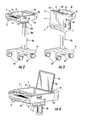
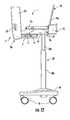
- FIG. 1is a perspective view of an embodiment of the cart of the invention with a laptop computer.
- FIG. 2is a perspective view of the cart of FIG. 1 without a computer in the closed position.
- FIG. 3is a perspective view of the cart of FIG. 1 without a computer in a storage position.
- FIG. 4is a detailed perspective view of the cart of FIG. 1 in the closed position.
- FIG. 5is a detailed perspective view of the cart of FIG. 1 in the forward, partially open position.
- FIG. 6is a more detailed perspective view of the cart as shown in FIG. 5 .
- FIG. 7is a detailed top perspective view of the cart as shown in FIG. 5
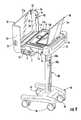
- FIG. 8is a partial section view of the cart as shown in FIG. 1 .
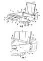
- FIG. 9is a back perspective view of the cart of FIG. 1 in an open position.
- FIG. 10is a front perspective view of the cart of FIG. 1 in an open position.
- FIG. 11is a top view of the cart of FIG. 1 in an open position.
- FIG. 12is a side view of the cart of FIG. 1 in an open position.
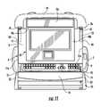
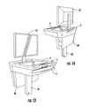
- FIG. 13is a front perspective view of an alternate embodiment of the cart of the invention.
- FIG. 14is a back perspective view of the cart of FIG. 13 .
- the cartcomprises a wraparound work platform 1 comprising a housing 2 .
- Housing 2is comprised of a lower housing portion 2 a and an upper housing portion 2 b that is movable relative to the lower housing portion 2 a and that defines a work surface 4 .
- the work platform 1is supported on an upright 20 that is supported on a base 16 .
- Base 16is supported on rollers or wheels 18 such that a user may push the cart over the floor.
- the upright 20may be height adjustable such that the height of the work platform 1 may be adjusted to comfortably accommodate a variety of users.
- a first vertical member 20 ais supported by base 16 and telescopically supports a second member 20 b .
- the work platform 1is supported by the second member 20 b .
- a lift mechanism 32may be provided to assist the user in moving the work platform 1 and setting the height of the upright 20 .
- the lift mechanism 32may comprise a hydraulic cylinder as shown in FIG. 8 , a counterweighted pulley system or other counterbalance mechanism that counterbalances the combined weight of the work platform 1 and the equipment supported by the work platform 1 .
- a suitable control 22is provided on the work platform 1 that may be manipulated by the user to operate the lift mechanism 32 and control the position of the work platform 1 .
- the lift mechanism 32may be designed to also support external loads such as may be applied by a user.
- the lift mechanism 32may also comprise a motorized lift system.
- the cartmay be made of a combination of materials including aluminum extrusions, sheet metal, cast metal and molded plastic.
- a cross support 5is mounted to the upright 20 such that adjustment of upright 20 raises and lowers the support 5 .
- the support 5supports a support platform 14 .
- the support platform 14forms a keyboard tray where the keyboard tray 14 may be movably mounted on rails (not shown) that are supported by the support 5 such that the tray 14 may be moved between a retracted position where it is located inside of the work platform 1 and an extended position where the keyboard 12 may be accessed by a user.
- a keyboard 12may be supported on a keyboard tray 14 such that it is positioned inside of the work platform 1 and below the technology box 6 when the tray 14 is retracted.
- the keyboard 12is a separate user interface from the user interfaces that form part of the laptop computer 10 and may be connected to the laptop computer 10 via a wired or wireless connection.
- the cart of the inventionintegrates the keyboard tray 14 and keyboard 12 into the work platform 1 and hides the keyboard tray mechanism from view.
- a mouse pad 3may also be supported on the platform 14 to support a mouse 9 .
- the mouse pad 3is slidably mounted to platform 14 on rails 31 such that it may be slid transversely out from under the platform 14 during use of the computer.
- Storage compartment 17may be secured to the bottom of mouse pad 3 for storing a mouse.
- the laptop computer 10may comprise a base 10 b that holds the laptop's integrated keyboard and mouse, battery and processor, and a monitor 10 a that is pivotably connected to the base as is known in the art.
- the base 10 balso includes a power button 10 c that may be used to turn the laptop computer 10 on and off ( FIGS. 7 and 11 ).
- the power button 10 c on a laptop computermay be located in various positions on the base but is typically located near the hinge between the base 10 b and the monitor 10 a.
- the lower housing portion 2 aalso includes a second support 11 that defines a substantially horizontal support platform.
- Support platform 11is positioned above the mouse pad 3 and keyboard tray 14 .
- Support platform 11may comprise upstanding walls 11 a that together define an upwardly opening technology box 6 that supports and surrounds the base 10 b of the laptop computer 10 .
- the technology box 6may be made of metal or other suitably strong material that securely holds the base 10 b of the laptop computer 10 .
- the lower housing portion 2 aalso comprises side members 13 that support the first platform 3 and the second platform 11 in a stacked spaced relationship relative to one another.
- a cross member 15is also connected to support 5 and may include a handle 19 that can be grasped by a user to propel the cart.
- the upper housing portion 2 bcomprises a substantially horizontal support platform 21 that defines the work surface 4 .
- the work surface 4may be used to support papers, equipment or the like.
- a handle 25may be formed at the front of upper housing portion 2 b that may be grasped by a user to propel the cart.
- Extending from the platform 21are two side members 23 that define the lateral sides of the upper housing portion 2 b .
- the side walls 11 a of the box 6may be dimensioned so as to abut or nearly abut the underside of platform 21 when the upper housing portion 2 b is in the horizontal position such that the platform 21 closes and secures the technology box 6 .
- the base 10 b of the laptop computer 10may be located in the technology box 6 such that when the upper housing portion 2 b is closed the base 10 b is trapped in the technology box 6 and the laptop computer 10 may not be removed from the cart.
- the side members 23 of the upper housing portion 2 bextend adjacent to and beyond the side members 13 of the lower housing portion 2 a such that when the upper housing portion 2 b is in the closed position the side members 23 overlap or wraparound the side members 13 to prevent access to the interior of the technology box 6 and to the base 10 b of laptop computer 10 .
- the end 21 a of support platform 21does not extend all of the way to the rear of the technology box 6 such that when the upper housing portion 2 b is closed, an upwardly opening gap 39 is created between the end 21 a of the support platform 21 and the end of technology box 6 .
- Gap 39allows limited access to the interior of the technology box 6 from the exterior of the cart such that the monitor 10 a of the lap top computer 10 may extend through gap 39 when base 10 b is secured in the technology box 6 .
- the gap 39is dimensioned such that end 21 a of platform 21 is closely adjacent to the monitor 10 a when the upper housing portion 10 b is in the closed position (as shown in FIG. 8 ).
- the upper housing portion 2 bis pivoted to the lower housing portion 2 a such that the upper housing portion 2 b may pivot between an open position where the technology box 6 may be accessed and a closed position where the upper housing portion 2 b secures the technology box 6 .
- the upper housing portion 2 bis also mounted for limited translational movement relative to the lower housing portion 2 a to allow access to the laptop's power button 10 c without unlocking the laptop from the cart.
- Each side wall 23 of the upper housing portion 2 bcomprises a front sliding hinge 41 ( FIG. 5 ) and a rear sliding latch 43 ( FIG. 9 ).
- the front sliding hinge 41 and rear sliding latch 43may be formed as recesses that receive pins to support the upper housing portion 2 b .
- the hinge 41 and latch 43may be formed in an elongated plate 29 that extends along the side wall 23 , or the latch 43 and hinge 41 may be formed in separate plates secured to the side walls 23 , or the latch 43 and hinge 41 may be formed as inmolded areas on side walls 23 or combinations of such structures.
- Sliding hinge 41comprises a linear slot 41 a that extends substantially horizontally when the upper housing portion 2 b is in the closed position.
- Latch 43comprises slot 47 that also extends substantially horizontally when the upper housing portion 2 b is in the closed position. The length of slots 41 a and 47 determines the distance the upper housing portion 2 b may be slid forward relative to the lower housing portion 2 a to allow limited access to the laptop 10 .
- Latch 43comprises an open portion 45 that opens toward the bottom of the upper housing portion 2 b and communicates with a first end of the slot 47 .
- a rear pin 49 and a front pin 51( FIG. 11 ) are mounted on each of the side walls 13 on the lower housing portion 2 a .
- the pins 49 and 51extend substantially horizontally from the walls 13 .
- the front pins 51extend into slots 41 a to create hinge that allows the upper housing portion 2 b to translate and rotate relative to the lower housing portion 2 b .
- the rear pins 49are positioned such that the pins 49 may extend into the rear sliding latches 43 through the open portions 45 when the upper housing portion 2 b is rotated onto the lower housing portion 2 a to the partially open position of FIGS. 5 and 6 .
- the upper housing portion 2 bIn this position the upper housing portion 2 b is positioned in a horizontal orientation with the pins 51 engaged with slots 41 and pins 49 engaged with slots 47 to support the upper housing portion 2 b in a substantially horizontal position. From this position the upper housing portion 2 b may be pushed rearward relative to the lower housing portion 2 a (in the direction of arrow A in FIG. 5 ) to the closed position of FIGS. 2 and 4 . As the upper housing portion is slid to the closed position, the slots 41 a and 47 slide over pins 51 and 49 , respectively, until the pins reach the ends of slots 41 a and 47 . The slots 41 a and 47 trap the pins 51 and 49 such that the upper housing portion 2 b may not be raised relative to the lower housing portion 2 a .
- the upper housing portion 2 bis moved linearly from the closed position of FIGS. 2 and 4 to the partially open position of FIGS. 5 and 6 . In this position the pins 49 are located in the open area 45 . The upper housing portion 25 may then be pivoted about the front pins 51 to the fully open position of FIGS. 9-12 .
- the upper housing portion 2 bis pivoted from the vertical open position of FIGS. 9-12 to the partially open position of FIGS. 5 and 6 .
- the rear pins 49enter the rear sliding latches 43 through the open portions 45 until slots 47 rest on pins 49 .
- the upper housing portion 2 bis then slid rearward relative to the lower housing portion 2 a to the position of FIGS. 1-3 .
- the engagement of the pins 49 with the slots 47prevents the upper housing portion 2 b from being rotated to the open position from the fully closed position.
- a pair of latches 61may be provided to connect the upper housing portion 2 b to the lower housing portion 2 a to prevent a user from inadvertently pulling the upper housing portion to the forward partially open position of FIGS. 5 and 6 .
- Each latch 61comprises a movable latch on one of the upper housing portion 2 b or lower housing portion 2 a that engages the other one of the upper housing portion or lower housing portion to releasably secure the housing portions 2 a and 2 b together.
- the latches 61may be depressed or otherwise manipulated by the user to unlatch the upper housing portion 2 b from the lower housing portion 2 a and allow the upper housing portion to slide forward relative to the lower housing portion.
- the latches 61may comprise deformable latches that are molded integrally with the housing portions or the latches may be a separate latch secured to the housing portions. While the latches hold the upper and lower housing portions together, they are not locked such that a user may separate the housings without unlocking a lock.
- the upper housing portion 2 bis able to slide forward a limited distance relative to the lower housing portion 2 a to provide limited access to the base 10 b of the laptop computer 10 .
- the forward movement of the upper housing portion 26increases the size of gap 39 to allow a user to access the power button 10 c of the laptop computer 10 ( FIG. 7 ); however, the gap is small enough that the base 10 b of the laptop computer 10 may not be removed from the technology box 6 .
- Limiting the distance the upper housing portion 2 b may move relative to the lower housing portion 2 aprevents the laptop computer from being removed from the cart by unauthorized person while allowing limited access to the base 10 b of laptop computer 10 .
- the work platform 2comprises buttons or latches 61 that can be depressed or unlatched to allow the upper housing portion 2 b to be pulled forward from a retracted, use position ( FIGS. 1 and 4 ) a fixed distance to a partially open, forward position ( FIGS. 5-7 ) allowing a user to access the power button of laptop 10 without allowing the laptop to be removed from the technology box 6 .
- the upper housing portionis moved rearward such that a minimum gap is maintained between the housing 2 and the lap top 10 .
- a lock 24is provided that prevents the upper housing portion 2 b from rotating from the partially open position of FIGS. 5-7 to the completely open position of FIGS. 9-12 unless the lock is unlocked.
- the lock 24is located on one of the lower and upper housing portions 2 a , 2 b and comprises a latch that engages a strike plate or other structure on the other of the upper and lower housing portions when the upper housing portion 2 b is in the forward, partially open position of FIGS. 5 and 6 .
- the lock 24does not prevent the upper housing portion 2 b from sliding between the closed position of FIGS.
- the lock 24is accessible only when the upper housing portion 2 b is moved to the forward, partially open position such that the lock is not visible or accessible during use of the cart. Once the lock 24 is made accessible by sliding the upper housing portion 2 b to the forward, partially open position an authorized person may open the lock 24 and rotate the upper housing portion 2 b to the completely open position of FIGS. 9-12 to open the technology box 6 to allow access to the laptop 10 for removal or service.
- the lock 24is shown as a keyed lock where a user must possess a key to open the cart; however, any suitable lock may be used including a standard combination lock, a keypad, a wireless controlled lock, a card reader or the like.
- the lower housing portion 2 a and upper housing portion 2 bdefine an internal technology box 6 as previously described.
- the technology box 6holds a lap top computer 10 such that the base 10 b of the laptop 10 is securely held in the technology box 6 while the screen 10 a extends above the work surface 4 .
- the technology box 6is located remotely from the work surface/keyboard stack such that a much smaller cart that has better ergonomics, lower manufacturing costs and reduced perceived size and weight is provided.
- the cart of the inventionreduces the number of seams that are detrimental to infection control by having a large wraparound work platform 2 where the upper portion 2 b wraps around the lower portion 2 a , the laptop base 10 b and the keyboard tray 14 .
- the work platform 2also conceals the technology box lock 24 during normal use, which eliminates another possible infection location.
- Infection controlis a growing concern in the hospital environment, especially for devices such as carts that travel from room to room.
- the cart of the inventionminimizes the potential infection locations without requiring the application of disinfectants or other similar substances to the plastic parts or metal paint.
- the cart of the inventionhas minimal seams and cleanable corners that assist the end user with infection control.
- the cart of the inventionalso limits access to the technology compartment and minimizes seams in “touch areas” while also selectively allowing access to the laptop power button.
- the cart of the inventionalso provides an improved orientation of the technology box relative to the keyboard and monitor, when set up as a LCD/CPU configuration as shown in FIGS. 13 and 14 .
- the cart as showndoes not use a universal technology box.
- the technology box 6 , work surface 4 and laptop computer 10may be positioned as previously described to provide the benefits described herein.
- the cart of the inventionis intended to be configured as a laptop cart in the large majority of applications, the cart is optimized for the laptop configuration.
- a clam shell enclosure 100may be mounted behind the keyboard and below the monitor to house the computer.
- Typical computer cartshave a considerable height discrepancy between keyboard height and work surface height that may range from 6.5 to 9 inches.
- the height discrepancyis typically the result of integrating a tech box to hold the CPU between the keyboard and work surface.
- the discrepancymeans that one or the other of the work surface and keyboard is not in an ergonomically correct position.
- the cart of the inventionhas a height difference of less than 4 inches between the work surface 4 and keyboard 12 because the technology box 100 for the CPU is located vertically behind the keyboard tray 14 instead of above it.
- the 4 inch height difference between the keyboard 12 and work surface 4also allows enough space for a laptop as shown in the configuration of FIGS. 1-12 . This orientation is a more efficient use of space when the cart is configured in the laptop configuration.
- a separate LCD monitor 32may be mounted so as to extend above the work surface 4 as shown in FIGS. 13 and 14 .
- the work platform 1may fold down when technology such as the laptop computer 10 is not present.
- the folding of the work platformreduces the packaged volume of the product.
- the base 16may also be removed from the upright 20 using a removable fastener such as screws or the like.
- the folded work platform 1shown in FIG. 3 , in conjunction with a removable base 16 makes the packaged (shipping) volume of the cart substantially smaller than existing carts.
- the folded cartmay be 30% smaller than prior carts allowing the cart to be shipped by existing overnight carriers.
- the removable base 16may be removed and packaged with the remainder of the cart for simple assembly on site.
- the side members 13are mounted for rotation relative to the upright 20 and rear wall 15 such that the work station 1 may be pivoted about a horizontal axis from the normal use position of FIG. 2 to the vertical storage and shipping position of FIG. 3 .
- a pair of stationary arms 62may be mounted to the upright 20 .
- the arms 62may be connected to the side members 13 at a locking pivot connection such that the side members 13 and the entire work platform 1 may rotate about the pivot from the horizontal use position of FIG. 2 to the vertical storage and shipping position of FIG. 3
Landscapes
- Engineering & Computer Science (AREA)
- General Engineering & Computer Science (AREA)
- Theoretical Computer Science (AREA)
- Mechanical Engineering (AREA)
- Computer Hardware Design (AREA)
- Human Computer Interaction (AREA)
- Physics & Mathematics (AREA)
- General Physics & Mathematics (AREA)
- Handcart (AREA)
- Casings For Electric Apparatus (AREA)
Abstract
Description
Claims (18)
Priority Applications (1)
| Application Number | Priority Date | Filing Date | Title |
|---|---|---|---|
| US13/399,212US8677911B2 (en) | 2011-02-18 | 2012-02-17 | Technology cart |
Applications Claiming Priority (2)
| Application Number | Priority Date | Filing Date | Title |
|---|---|---|---|
| US201161444290P | 2011-02-18 | 2011-02-18 | |
| US13/399,212US8677911B2 (en) | 2011-02-18 | 2012-02-17 | Technology cart |
Publications (2)
| Publication Number | Publication Date |
|---|---|
| US20120236496A1 US20120236496A1 (en) | 2012-09-20 |
| US8677911B2true US8677911B2 (en) | 2014-03-25 |
Family
ID=46828280
Family Applications (1)
| Application Number | Title | Priority Date | Filing Date |
|---|---|---|---|
| US13/399,212Active2032-07-14US8677911B2 (en) | 2011-02-18 | 2012-02-17 | Technology cart |
Country Status (1)
| Country | Link |
|---|---|
| US (1) | US8677911B2 (en) |
Cited By (13)
| Publication number | Priority date | Publication date | Assignee | Title |
|---|---|---|---|---|
| US20130025801A1 (en)* | 2010-04-23 | 2013-01-31 | Goeranson Dag | Arrangement with a base plate and a covering hood for a screen |
| US20140014790A1 (en)* | 2013-04-10 | 2014-01-16 | Mel White | Kiosks for Electronic Devices |
| USD720165S1 (en)* | 2012-06-01 | 2014-12-30 | Steelcase Inc. | Mobile display device |
| US20150090162A1 (en)* | 2013-10-01 | 2015-04-02 | Stephanie Vlosich | First electronic tablet high chair |
| USD730011S1 (en)* | 2014-02-21 | 2015-05-19 | Rubbermaid Commercial Products Llc | Cart |
| US20150289681A1 (en)* | 2014-04-11 | 2015-10-15 | Sungal Corp. | Low voltage plug and play display system for general application in gondola systems |
| US20150340892A1 (en)* | 2014-05-21 | 2015-11-26 | Palmer Hamilton, Llc | Mobile charging table |
| US20160367329A1 (en)* | 2014-02-17 | 2016-12-22 | Claronav Inc. | Medical cart |
| US9933106B2 (en)* | 2013-03-14 | 2018-04-03 | Capsa Solutions, Llc | Height adjustable support |
| USD863559S1 (en) | 2013-03-01 | 2019-10-15 | Capsa Solutions, Llc | Hospital cart |
| US10453572B1 (en) | 2012-03-01 | 2019-10-22 | Capsa Solutions, Llc | System and method for a hospital cart |
| USD878068S1 (en)* | 2018-04-04 | 2020-03-17 | Chin-Chu Li | Cart |
| US11284711B2 (en)* | 2018-02-22 | 2022-03-29 | Jaco, Inc. | Mobile workstation |
Families Citing this family (15)
| Publication number | Priority date | Publication date | Assignee | Title |
|---|---|---|---|---|
| US8662605B2 (en) | 2011-02-18 | 2014-03-04 | Rubbermaid Incorporated | Mobile technology cabinet |
| US9027940B2 (en)* | 2012-09-26 | 2015-05-12 | Ergotron, Inc. | Work surface opening mechanism |
| WO2014129881A1 (en)* | 2013-02-20 | 2014-08-28 | Universite Mohammed V Souissi | Device for supporting portable computers with a cushion and a mobile table provided with a rotation system. "smart ordi bracket". |
| US9785187B2 (en) | 2014-08-07 | 2017-10-10 | Microsoft Technology Licensing, Llc | Modular computing device |
| US9430001B2 (en)* | 2015-01-05 | 2016-08-30 | Microsoft Technology Licensing, Llc | Modular computing device |
| CN105433594A (en)* | 2016-01-04 | 2016-03-30 | 湖南城市学院 | Movable teaching worktable for experimental guidance teacher |
| GB2553759A (en)* | 2016-08-17 | 2018-03-21 | Neo One Ltd | Improvements in supporting computer tablets & laptops |
| CN107763411B (en)* | 2017-10-25 | 2020-02-04 | 北京工业大学 | Industrial camera fine adjustment support for monitoring micro-hole electric spark machining in situ |
| DE102017010461A1 (en)* | 2017-11-13 | 2019-05-16 | Carl Freudenberg Kg | Cleaning trolley and frame for it |
| CA3192834A1 (en) | 2018-03-02 | 2019-09-06 | Ergotron, Inc. | Height adjustable platforms and associated mechanisms |
| CA3092642C (en) | 2018-03-02 | 2023-07-04 | Ergotron, Inc. | Height adjustable platforms and associated mechanisms |
| WO2020190479A1 (en)* | 2019-03-15 | 2020-09-24 | Covidien Lp | Cart for medical equipment |
| US11613286B2 (en)* | 2019-09-06 | 2023-03-28 | Covidien Lp | Cart for medical equipment |
| US12000526B2 (en)* | 2022-01-14 | 2024-06-04 | Scales Plus, LLC | Portable scale stand assembly |
| CN114582483B (en)* | 2022-03-07 | 2024-11-15 | 山东勤成健康科技股份有限公司 | A medical laboratory information sharing device based on WIFI |
Citations (84)
| Publication number | Priority date | Publication date | Assignee | Title |
|---|---|---|---|---|
| US844083A (en) | 1906-10-31 | 1907-02-12 | Louis Barrella | Arm-support for telephones. |
| US1730028A (en) | 1927-08-08 | 1929-10-01 | Ball Howard | Adjustable scaffolding |
| US2077337A (en) | 1935-02-08 | 1937-04-13 | Axel F Lifvendahl | Seat construction |
| US3089742A (en) | 1961-04-24 | 1963-05-14 | Earl A Powell | Portable work counter |
| US3862734A (en) | 1973-05-17 | 1975-01-28 | Berthold Ag H | Instrument head mounting |
| US3999733A (en) | 1975-02-18 | 1976-12-28 | Coach & Car Equipment Corporation | Adjustable vehicle seat |
| DE3409990A1 (en) | 1984-03-19 | 1984-07-12 | Hermann 4905 Spenge Dröge | Device for a lowerable wall cabinet |
| US4516751A (en) | 1982-09-17 | 1985-05-14 | Charles Westbrook | Wall bracket system |
| US4544121A (en) | 1982-02-03 | 1985-10-01 | Tokyo Kogaku Kikai Kabushiki Kaisha | Support apparatus for medical appliance |
| US4687167A (en) | 1985-10-23 | 1987-08-18 | Skalka Gerald P | Multi-position computer support |
| US4836478A (en) | 1987-10-15 | 1989-06-06 | Ergotron, Inc. | Suspension system for personal computers and monitors |
| US4907773A (en) | 1988-08-15 | 1990-03-13 | National Gypsum Company | Adjustable mounting surface |
| US5007608A (en) | 1989-08-28 | 1991-04-16 | Kim Manufacturing Company | Television wall bracket |
| US5240215A (en) | 1992-08-24 | 1993-08-31 | Automated Monitoring And Control International, Inc. | Universal computer support bracket |
| GB2285911A (en) | 1993-12-22 | 1995-08-02 | Flexistoring Limited | Wall mountable support and storage receptacle |
| US5487525A (en) | 1991-10-18 | 1996-01-30 | Drabczyk; Matthew P. | Adjustable keyboard holder for workstations |
| US5630566A (en) | 1995-05-30 | 1997-05-20 | Case; Laura | Portable ergonomic work station |
| US5632462A (en) | 1996-01-18 | 1997-05-27 | Kallas; John J. | Computer mount retractable for police vehicles |
| USD380736S (en) | 1996-04-16 | 1997-07-08 | Ergotron, Inc. | Cable routing duct |
| US5738316A (en) | 1995-04-03 | 1998-04-14 | Ergotron, Inc. | Vertical work center |
| US5743503A (en) | 1996-03-08 | 1998-04-28 | Ergotron, Inc. | Computer suspension system |
| US5791623A (en) | 1995-03-07 | 1998-08-11 | Louridas; Michael C. | Easel mounting device |
| US5797568A (en) | 1996-05-30 | 1998-08-25 | Telefonica De Espana S.A. | Multi-position television monitor stand |
| US5842672A (en) | 1996-06-07 | 1998-12-01 | Ergotron, Inc. | Mounting system for flat panel display, keyboard and stand |
| US5876008A (en) | 1995-01-17 | 1999-03-02 | Ergotron, Inc. | Suspension system for video monitor or other equipment |
| USD412161S (en) | 1998-10-21 | 1999-07-20 | Ergotron, Inc. | Base for a computer display |
| USD413110S (en) | 1998-10-19 | 1999-08-24 | Ergotron, Inc. | Stand for a computer display |
| US5944896A (en) | 1997-09-24 | 1999-08-31 | Lawson Screen Products, Inc. | Adjustable support for print screens |
| US6012693A (en) | 1998-02-19 | 2000-01-11 | Ergotron, Inc. | Multi-function display mounting system |
| FR2783412A1 (en) | 1998-09-18 | 2000-03-24 | Lhd Lab Hygiene Dietetique | Wound dressings has flexible open net structure coated with a non-adherent gel which has matrix of a highly plasticized hydrophobic elastomer with hydrophilic particles of a hydrocolloid |
| USD423745S (en) | 1998-12-03 | 2000-04-25 | Ergotron, Inc. | Slim line arm |
| USD431736S (en) | 1998-11-12 | 2000-10-10 | Ergotron, Inc. | Rack |
| US6189849B1 (en) | 1998-05-06 | 2001-02-20 | Ergotron, Inc. | Lift system |
| US6233791B1 (en) | 1999-01-05 | 2001-05-22 | Ergotron, Inc. | Cable management system |
| USD450903S1 (en) | 2000-10-13 | 2001-11-20 | Ergotron, Inc. | Cart for a computer station |
| US6354549B2 (en) | 1999-11-02 | 2002-03-12 | Ergotron, Inc. | Ratcheted pivot |
| US6367756B1 (en) | 2000-07-07 | 2002-04-09 | James Wang | Adjustable device support and anchor means arrangement |
| USD455916S1 (en) | 1998-11-04 | 2002-04-23 | Ergotron, Inc. | Large area network work station |
| US6380484B1 (en) | 1996-11-12 | 2002-04-30 | Ergotron, Inc. | Cable routing duct |
| US6409134B1 (en) | 1999-06-07 | 2002-06-25 | Innovative Office Products, Inc. | Arm apparatus for mounting electronic devices with cable management system |
| US6435109B1 (en)* | 1996-09-12 | 2002-08-20 | Sculptor Developmental Technologies, Inc. | Mobile workstation |
| US6493220B1 (en)* | 1998-09-18 | 2002-12-10 | Lxe, Inc. | Mobile clinical workstation |
| US20030057340A1 (en) | 2001-09-24 | 2003-03-27 | Tempus Computers Limited | Mounting and containment system for portable computers |
| US6581887B2 (en) | 2001-11-19 | 2003-06-24 | Mark R Lapidez | Rotatable television mounting assembly |
| USD477325S1 (en) | 2002-04-24 | 2003-07-15 | Ergotron, Inc. | Support for flat panel monitor display unit |
| USD477606S1 (en) | 2002-04-24 | 2003-07-22 | Ergotron, Inc. | Support for flat panel monitor display unit |
| US6709058B1 (en) | 1999-04-09 | 2004-03-23 | Humanscale Corp. | Ergonomic chair |
| US6712008B1 (en) | 2001-05-11 | 2004-03-30 | Bruce C. Habenicht | Portable computer work station assembly |
| US6783105B2 (en) | 2001-06-20 | 2004-08-31 | Innovative Office Products, Inc. | Adjustable display arm for computer components |
| US6863252B2 (en) | 2000-03-30 | 2005-03-08 | Peter Thomas Bosson | Display device support system |
| US20050062370A1 (en) | 2002-10-14 | 2005-03-24 | Miller Grover L. | Article of furniture having storage components |
| US6883764B1 (en) | 1997-03-12 | 2005-04-26 | Humanscale Corp. | Keyboard support mechanism |
| US6994306B1 (en) | 2000-11-28 | 2006-02-07 | Constant Force Technology, Llc | Monitor support system |
| US6997422B2 (en) | 2002-08-21 | 2006-02-14 | Ergotron, Inc. | Stand |
| US7032870B2 (en) | 2000-11-28 | 2006-04-25 | Ergotron, Inc. | Methods and apparatus for generating force and torque |
| US7048242B2 (en) | 2003-06-13 | 2006-05-23 | Innovative Office Products, Inc. | Tilter apparatus for electronic device having bias assembly |
| US7063296B2 (en) | 2003-06-13 | 2006-06-20 | Innovative Office Products, Inc. | Rail mounting apparatus for electronic device |
| US7066435B2 (en) | 2003-12-04 | 2006-06-27 | Innovation Office Products, Inc. | Universal wall mounting bracket |
| US7147190B2 (en) | 2001-06-16 | 2006-12-12 | Humanscale Corporation | Multipositional accessory shelf for a computer mouse or other accessory items |
| US7152488B2 (en) | 2003-06-04 | 2006-12-26 | Leica Microsystems Semiconductor Gmbh | System operating unit |
| USD535432S1 (en) | 2004-07-07 | 2007-01-16 | Humanscale Corporation | Lamp shade |
| USD537323S1 (en) | 2005-06-10 | 2007-02-27 | Humanscale Corporation | Device support arm |
| US7195213B2 (en) | 2003-03-31 | 2007-03-27 | O'sullivan Industries Inc. | Adjustable television stand |
| US7252277B2 (en) | 2003-01-17 | 2007-08-07 | Ergotron, Inc. | Support arm |
| US20070227409A1 (en)* | 2006-03-29 | 2007-10-04 | Ching-Shan Chu | UPS uninterruptible power supply mobile computer table structure |
| US20070259554A1 (en) | 2006-05-04 | 2007-11-08 | Ergotron, Inc. | Stand system and method |
| US7303173B2 (en) | 2001-06-13 | 2007-12-04 | Humanscale Corporation | Shelf adjustment mechanism |
| US20070295870A1 (en) | 2006-06-12 | 2007-12-27 | Peterson Erik R | Wall mounted workstation |
| US20080001043A1 (en)* | 2006-06-20 | 2008-01-03 | Meyer Christopher E | Secure shelf for technology workstand |
| US20080026892A1 (en) | 2006-07-26 | 2008-01-31 | Ergotron, Inc. | Balanced moment lift system and method |
| US20080142660A1 (en) | 2006-12-18 | 2008-06-19 | Goldberg Mark A | Wall mounted workstation |
| US20080168930A1 (en) | 2007-01-11 | 2008-07-17 | Enovateit, Llc | Privacy Protecting Wall-Mounted Workstation |
| US20080258029A1 (en) | 2007-04-17 | 2008-10-23 | Zhong-Yue Zhang | Wall-mounting support assembly for flat-panel monitor |
| USD584908S1 (en) | 1999-04-09 | 2009-01-20 | Humanscale Corporation | Twin arm headrest |
| US7481170B2 (en) | 2005-08-05 | 2009-01-27 | Humanscale Corporation | Accessory shelf mounting mechanism |
| US7487940B2 (en) | 2003-06-13 | 2009-02-10 | Humanscale Corporation | Laptop holder |
| US20090212184A1 (en) | 2005-01-20 | 2009-08-27 | Hensley Kim & Edgington, LLC | Articulated Mounting Systems And Bearings For Joints Thereof |
| US7621544B2 (en)* | 2005-06-13 | 2009-11-24 | Rossini Alfred P | Mobile flat panel monitor and computer cart |
| US7954780B2 (en) | 2002-06-11 | 2011-06-07 | Milestone Av Technologies Llc | Adjustable self-balancing flat panel display mounting system |
| US20110233350A1 (en) | 2010-01-29 | 2011-09-29 | Rubbermaid Incorporated | Work station with height adjustment lock |
| US8180485B2 (en)* | 2006-02-11 | 2012-05-15 | Omnicell, Inc. | Medication dispensing cart |
| US8245652B2 (en)* | 2010-03-25 | 2012-08-21 | Modernsolid Industrial Co., Ltd. | Medical worktable |
| US20120212116A1 (en) | 2011-02-18 | 2012-08-23 | Rubbermaid Incorporated | Mobile technology cabinet |
| US8526176B2 (en)* | 1998-09-18 | 2013-09-03 | Intermetro Industries Corporation | Mobile computer workstation |
- 2012
- 2012-02-17USUS13/399,212patent/US8677911B2/enactiveActive
Patent Citations (95)
| Publication number | Priority date | Publication date | Assignee | Title |
|---|---|---|---|---|
| US844083A (en) | 1906-10-31 | 1907-02-12 | Louis Barrella | Arm-support for telephones. |
| US1730028A (en) | 1927-08-08 | 1929-10-01 | Ball Howard | Adjustable scaffolding |
| US2077337A (en) | 1935-02-08 | 1937-04-13 | Axel F Lifvendahl | Seat construction |
| US3089742A (en) | 1961-04-24 | 1963-05-14 | Earl A Powell | Portable work counter |
| US3862734A (en) | 1973-05-17 | 1975-01-28 | Berthold Ag H | Instrument head mounting |
| US3999733A (en) | 1975-02-18 | 1976-12-28 | Coach & Car Equipment Corporation | Adjustable vehicle seat |
| US4544121A (en) | 1982-02-03 | 1985-10-01 | Tokyo Kogaku Kikai Kabushiki Kaisha | Support apparatus for medical appliance |
| US4516751A (en) | 1982-09-17 | 1985-05-14 | Charles Westbrook | Wall bracket system |
| DE3409990A1 (en) | 1984-03-19 | 1984-07-12 | Hermann 4905 Spenge Dröge | Device for a lowerable wall cabinet |
| US4687167A (en) | 1985-10-23 | 1987-08-18 | Skalka Gerald P | Multi-position computer support |
| US4836478A (en) | 1987-10-15 | 1989-06-06 | Ergotron, Inc. | Suspension system for personal computers and monitors |
| US4907773A (en) | 1988-08-15 | 1990-03-13 | National Gypsum Company | Adjustable mounting surface |
| US5007608A (en) | 1989-08-28 | 1991-04-16 | Kim Manufacturing Company | Television wall bracket |
| US5487525A (en) | 1991-10-18 | 1996-01-30 | Drabczyk; Matthew P. | Adjustable keyboard holder for workstations |
| US5240215A (en) | 1992-08-24 | 1993-08-31 | Automated Monitoring And Control International, Inc. | Universal computer support bracket |
| GB2285911A (en) | 1993-12-22 | 1995-08-02 | Flexistoring Limited | Wall mountable support and storage receptacle |
| US5876008A (en) | 1995-01-17 | 1999-03-02 | Ergotron, Inc. | Suspension system for video monitor or other equipment |
| US5791623A (en) | 1995-03-07 | 1998-08-11 | Louridas; Michael C. | Easel mounting device |
| US5738316A (en) | 1995-04-03 | 1998-04-14 | Ergotron, Inc. | Vertical work center |
| US5630566A (en) | 1995-05-30 | 1997-05-20 | Case; Laura | Portable ergonomic work station |
| US5632462A (en) | 1996-01-18 | 1997-05-27 | Kallas; John J. | Computer mount retractable for police vehicles |
| US5743503A (en) | 1996-03-08 | 1998-04-28 | Ergotron, Inc. | Computer suspension system |
| USD380736S (en) | 1996-04-16 | 1997-07-08 | Ergotron, Inc. | Cable routing duct |
| US5797568A (en) | 1996-05-30 | 1998-08-25 | Telefonica De Espana S.A. | Multi-position television monitor stand |
| US20030001057A1 (en) | 1996-06-07 | 2003-01-02 | Ergotron, Inc. | Pivot assembly and support system |
| US6015120A (en) | 1996-06-07 | 2000-01-18 | Ergotron, Inc. | Desktop flat panel display support system |
| US5924665A (en) | 1996-06-07 | 1999-07-20 | Ergotron, Inc. | Ceiling system for a flat panel display |
| US5842672A (en) | 1996-06-07 | 1998-12-01 | Ergotron, Inc. | Mounting system for flat panel display, keyboard and stand |
| US6419196B1 (en) | 1996-06-07 | 2002-07-16 | Ergotron, Inc. | Pivot assembly and support system |
| US5947429A (en) | 1996-06-07 | 1999-09-07 | Ergotron, Inc. | Table mount system for flat panel display |
| US5967479A (en) | 1996-06-07 | 1999-10-19 | Ergotron, Inc. | Keyboard tray on support arm with pivoting brake |
| US5992809A (en) | 1996-06-07 | 1999-11-30 | Ergotron, Inc. | Mounting system for flat panel display, keyboard, and stand |
| US6019332A (en) | 1996-06-07 | 2000-02-01 | Ergotron, Inc. | Pivot/ratchet assembly and support system |
| US6435109B1 (en)* | 1996-09-12 | 2002-08-20 | Sculptor Developmental Technologies, Inc. | Mobile workstation |
| US6380484B1 (en) | 1996-11-12 | 2002-04-30 | Ergotron, Inc. | Cable routing duct |
| US6883764B1 (en) | 1997-03-12 | 2005-04-26 | Humanscale Corp. | Keyboard support mechanism |
| US5944896A (en) | 1997-09-24 | 1999-08-31 | Lawson Screen Products, Inc. | Adjustable support for print screens |
| US6012693A (en) | 1998-02-19 | 2000-01-11 | Ergotron, Inc. | Multi-function display mounting system |
| US6189849B1 (en) | 1998-05-06 | 2001-02-20 | Ergotron, Inc. | Lift system |
| FR2783412A1 (en) | 1998-09-18 | 2000-03-24 | Lhd Lab Hygiene Dietetique | Wound dressings has flexible open net structure coated with a non-adherent gel which has matrix of a highly plasticized hydrophobic elastomer with hydrophilic particles of a hydrocolloid |
| US8526176B2 (en)* | 1998-09-18 | 2013-09-03 | Intermetro Industries Corporation | Mobile computer workstation |
| US6493220B1 (en)* | 1998-09-18 | 2002-12-10 | Lxe, Inc. | Mobile clinical workstation |
| USD413110S (en) | 1998-10-19 | 1999-08-24 | Ergotron, Inc. | Stand for a computer display |
| USD412161S (en) | 1998-10-21 | 1999-07-20 | Ergotron, Inc. | Base for a computer display |
| USD455916S1 (en) | 1998-11-04 | 2002-04-23 | Ergotron, Inc. | Large area network work station |
| USD431736S (en) | 1998-11-12 | 2000-10-10 | Ergotron, Inc. | Rack |
| USD423745S (en) | 1998-12-03 | 2000-04-25 | Ergotron, Inc. | Slim line arm |
| US6233791B1 (en) | 1999-01-05 | 2001-05-22 | Ergotron, Inc. | Cable management system |
| US7475946B2 (en) | 1999-04-09 | 2009-01-13 | Humanscale Corporation | Ergonomic armrest |
| USD584908S1 (en) | 1999-04-09 | 2009-01-20 | Humanscale Corporation | Twin arm headrest |
| US6709058B1 (en) | 1999-04-09 | 2004-03-23 | Humanscale Corp. | Ergonomic chair |
| US6959965B2 (en) | 1999-04-09 | 2005-11-01 | Humanscale Corporation | Ergonomic chair |
| US6409134B1 (en) | 1999-06-07 | 2002-06-25 | Innovative Office Products, Inc. | Arm apparatus for mounting electronic devices with cable management system |
| US6354549B2 (en) | 1999-11-02 | 2002-03-12 | Ergotron, Inc. | Ratcheted pivot |
| US6863252B2 (en) | 2000-03-30 | 2005-03-08 | Peter Thomas Bosson | Display device support system |
| US6367756B1 (en) | 2000-07-07 | 2002-04-09 | James Wang | Adjustable device support and anchor means arrangement |
| USD450903S1 (en) | 2000-10-13 | 2001-11-20 | Ergotron, Inc. | Cart for a computer station |
| US6994306B1 (en) | 2000-11-28 | 2006-02-07 | Constant Force Technology, Llc | Monitor support system |
| US7032870B2 (en) | 2000-11-28 | 2006-04-25 | Ergotron, Inc. | Methods and apparatus for generating force and torque |
| US6712008B1 (en) | 2001-05-11 | 2004-03-30 | Bruce C. Habenicht | Portable computer work station assembly |
| US7303173B2 (en) | 2001-06-13 | 2007-12-04 | Humanscale Corporation | Shelf adjustment mechanism |
| US7147190B2 (en) | 2001-06-16 | 2006-12-12 | Humanscale Corporation | Multipositional accessory shelf for a computer mouse or other accessory items |
| US6783105B2 (en) | 2001-06-20 | 2004-08-31 | Innovative Office Products, Inc. | Adjustable display arm for computer components |
| US20030057340A1 (en) | 2001-09-24 | 2003-03-27 | Tempus Computers Limited | Mounting and containment system for portable computers |
| US6581887B2 (en) | 2001-11-19 | 2003-06-24 | Mark R Lapidez | Rotatable television mounting assembly |
| USD477606S1 (en) | 2002-04-24 | 2003-07-22 | Ergotron, Inc. | Support for flat panel monitor display unit |
| USD477325S1 (en) | 2002-04-24 | 2003-07-15 | Ergotron, Inc. | Support for flat panel monitor display unit |
| US7954780B2 (en) | 2002-06-11 | 2011-06-07 | Milestone Av Technologies Llc | Adjustable self-balancing flat panel display mounting system |
| US6997422B2 (en) | 2002-08-21 | 2006-02-14 | Ergotron, Inc. | Stand |
| US20050062370A1 (en) | 2002-10-14 | 2005-03-24 | Miller Grover L. | Article of furniture having storage components |
| US7252277B2 (en) | 2003-01-17 | 2007-08-07 | Ergotron, Inc. | Support arm |
| US7195213B2 (en) | 2003-03-31 | 2007-03-27 | O'sullivan Industries Inc. | Adjustable television stand |
| US7152488B2 (en) | 2003-06-04 | 2006-12-26 | Leica Microsystems Semiconductor Gmbh | System operating unit |
| US7048242B2 (en) | 2003-06-13 | 2006-05-23 | Innovative Office Products, Inc. | Tilter apparatus for electronic device having bias assembly |
| US7472458B2 (en) | 2003-06-13 | 2009-01-06 | Innovative Office Products, Inc. | Tilter apparatus for electronic device having bias assembly |
| US7063296B2 (en) | 2003-06-13 | 2006-06-20 | Innovative Office Products, Inc. | Rail mounting apparatus for electronic device |
| US7487940B2 (en) | 2003-06-13 | 2009-02-10 | Humanscale Corporation | Laptop holder |
| US7066435B2 (en) | 2003-12-04 | 2006-06-27 | Innovation Office Products, Inc. | Universal wall mounting bracket |
| USD535432S1 (en) | 2004-07-07 | 2007-01-16 | Humanscale Corporation | Lamp shade |
| US20090212184A1 (en) | 2005-01-20 | 2009-08-27 | Hensley Kim & Edgington, LLC | Articulated Mounting Systems And Bearings For Joints Thereof |
| USD537323S1 (en) | 2005-06-10 | 2007-02-27 | Humanscale Corporation | Device support arm |
| US7621544B2 (en)* | 2005-06-13 | 2009-11-24 | Rossini Alfred P | Mobile flat panel monitor and computer cart |
| US7481170B2 (en) | 2005-08-05 | 2009-01-27 | Humanscale Corporation | Accessory shelf mounting mechanism |
| US8180485B2 (en)* | 2006-02-11 | 2012-05-15 | Omnicell, Inc. | Medication dispensing cart |
| US20070227409A1 (en)* | 2006-03-29 | 2007-10-04 | Ching-Shan Chu | UPS uninterruptible power supply mobile computer table structure |
| US20070259554A1 (en) | 2006-05-04 | 2007-11-08 | Ergotron, Inc. | Stand system and method |
| US20070295870A1 (en) | 2006-06-12 | 2007-12-27 | Peterson Erik R | Wall mounted workstation |
| US20080001043A1 (en)* | 2006-06-20 | 2008-01-03 | Meyer Christopher E | Secure shelf for technology workstand |
| US20080026892A1 (en) | 2006-07-26 | 2008-01-31 | Ergotron, Inc. | Balanced moment lift system and method |
| US20080142660A1 (en) | 2006-12-18 | 2008-06-19 | Goldberg Mark A | Wall mounted workstation |
| US20080168930A1 (en) | 2007-01-11 | 2008-07-17 | Enovateit, Llc | Privacy Protecting Wall-Mounted Workstation |
| US20080258029A1 (en) | 2007-04-17 | 2008-10-23 | Zhong-Yue Zhang | Wall-mounting support assembly for flat-panel monitor |
| US20110233350A1 (en) | 2010-01-29 | 2011-09-29 | Rubbermaid Incorporated | Work station with height adjustment lock |
| US8245652B2 (en)* | 2010-03-25 | 2012-08-21 | Modernsolid Industrial Co., Ltd. | Medical worktable |
| US20120212116A1 (en) | 2011-02-18 | 2012-08-23 | Rubbermaid Incorporated | Mobile technology cabinet |
Non-Patent Citations (2)
| Title |
|---|
| U.S. Appl. No. 12/636,181, Office Action, Feb. 29, 2012. |
| U.S. Appl. No. 12/636,181, Office Action, Oct. 21, 2011. |
Cited By (20)
| Publication number | Priority date | Publication date | Assignee | Title |
|---|---|---|---|---|
| US9615681B2 (en)* | 2010-04-23 | 2017-04-11 | Dag Göranson | Arrangement with a base plate and a covering hood for a screen |
| US20130025801A1 (en)* | 2010-04-23 | 2013-01-31 | Goeranson Dag | Arrangement with a base plate and a covering hood for a screen |
| US10453572B1 (en) | 2012-03-01 | 2019-10-22 | Capsa Solutions, Llc | System and method for a hospital cart |
| USD720165S1 (en)* | 2012-06-01 | 2014-12-30 | Steelcase Inc. | Mobile display device |
| USD863559S1 (en) | 2013-03-01 | 2019-10-15 | Capsa Solutions, Llc | Hospital cart |
| US9933106B2 (en)* | 2013-03-14 | 2018-04-03 | Capsa Solutions, Llc | Height adjustable support |
| US20140014790A1 (en)* | 2013-04-10 | 2014-01-16 | Mel White | Kiosks for Electronic Devices |
| US8991775B2 (en)* | 2013-04-10 | 2015-03-31 | Mel White | Kiosks for electronic devices |
| US20150090162A1 (en)* | 2013-10-01 | 2015-04-02 | Stephanie Vlosich | First electronic tablet high chair |
| US9167911B2 (en)* | 2013-10-01 | 2015-10-27 | Stephanie Vlosich | First electronic tablet high chair |
| US9855109B2 (en)* | 2014-02-17 | 2018-01-02 | Claronav Inc. | Medical cart |
| US20160367329A1 (en)* | 2014-02-17 | 2016-12-22 | Claronav Inc. | Medical cart |
| USD730011S1 (en)* | 2014-02-21 | 2015-05-19 | Rubbermaid Commercial Products Llc | Cart |
| USD762339S1 (en) | 2014-02-21 | 2016-07-26 | Capsa Solutions, Llc | Cart |
| US9420901B2 (en)* | 2014-04-11 | 2016-08-23 | Sungal Corp. | Low voltage plug and play display system for general application in gondola systems |
| US20150289681A1 (en)* | 2014-04-11 | 2015-10-15 | Sungal Corp. | Low voltage plug and play display system for general application in gondola systems |
| US9755446B2 (en)* | 2014-05-21 | 2017-09-05 | Palmer Hamilton, Llc | Mobile charging table with hinged tabletop and selectively accessible battery compartment opening |
| US20150340892A1 (en)* | 2014-05-21 | 2015-11-26 | Palmer Hamilton, Llc | Mobile charging table |
| US11284711B2 (en)* | 2018-02-22 | 2022-03-29 | Jaco, Inc. | Mobile workstation |
| USD878068S1 (en)* | 2018-04-04 | 2020-03-17 | Chin-Chu Li | Cart |
Also Published As
| Publication number | Publication date |
|---|---|
| US20120236496A1 (en) | 2012-09-20 |
Similar Documents
| Publication | Publication Date | Title |
|---|---|---|
| US8677911B2 (en) | Technology cart | |
| US8662605B2 (en) | Mobile technology cabinet | |
| AU2019203695B2 (en) | Mobile computer workstation | |
| US7828253B2 (en) | Secure shelf for technology workstand | |
| US20090315287A1 (en) | Mobile Cart | |
| AU2009244648B2 (en) | Tool storage cabinet | |
| US7278644B2 (en) | Portable workspace for laptop computers | |
| CN104093389B (en) | Computing Cart with Sliding Work Surface | |
| US6454064B1 (en) | Workstation container | |
| US8006986B1 (en) | Multi-station voting booth with storage/utility cart | |
| US20090039743A1 (en) | Movable Monitor And Keyboard Storage System For A Worksurface | |
| US20100231102A1 (en) | Stowable and releasably securable mobile structure | |
| US6543369B1 (en) | Combination bedside and overbed table | |
| US6752477B2 (en) | Portable work station for a laptop computer | |
| US20250212837A1 (en) | Large collapsible animal containment assembly | |
| CA3231247A1 (en) | Wheeled container assembly | |
| US7694981B2 (en) | Multiple use, transformable cart | |
| US6574807B1 (en) | Furniture bed | |
| US20240399561A1 (en) | Tool chest with slidable and pivotable lids | |
| JP2019141155A (en) | Storage furniture | |
| WO2006009531A2 (en) | Laptop computer bin assembly for a worksurface | |
| JPH03297500A (en) | Ironing board with storage | |
| JP3064608U (en) | Office equipment storage | |
| GB2580383A (en) | Storage cubicle for a piece of equipment, e.g a wheelchair ramp, and public transportation vehicle provided with a storage cubicle |
Legal Events
| Date | Code | Title | Description |
|---|---|---|---|
| AS | Assignment | Owner name:RUBBERMAID INCORPORATED, NORTH CAROLINA Free format text:ASSIGNMENT OF ASSIGNORS INTEREST;ASSIGNOR:MCRORIE, ROBERT GRANT;REEL/FRAME:028319/0201 Effective date:20120605 | |
| STCF | Information on status: patent grant | Free format text:PATENTED CASE | |
| AS | Assignment | Owner name:THE PRIVATEBANK AND TRUST COMPANY, AS ADMINISTRATIVE AGENT, ILLINOIS Free format text:REAFFIRMATION OF AND FIRST AMENDMENT TO SECOND AMENDED AND RESTATED PATENT AND TRADEMARK SECURITY AGREEMENT;ASSIGNORS:CAPSA SOLUTIONS LLC (F/K/A INTERNATIONAL RETAIL SERVICES GROUP, LLC);CAPSA INTERNATIONAL SALES CORPORATION;IRSG HOLDINGS, LLC;REEL/FRAME:036337/0946 Effective date:20150806 Owner name:THE PRIVATEBANK AND TRUST COMPANY, AS ADMINISTRATI Free format text:REAFFIRMATION OF AND FIRST AMENDMENT TO SECOND AMENDED AND RESTATED PATENT AND TRADEMARK SECURITY AGREEMENT;ASSIGNORS:CAPSA SOLUTIONS LLC (F/K/A INTERNATIONAL RETAIL SERVICES GROUP, LLC);CAPSA INTERNATIONAL SALES CORPORATION;IRSG HOLDINGS, LLC;REEL/FRAME:036337/0946 Effective date:20150806 | |
| AS | Assignment | Owner name:CAPSA SOLUTIONS, LLC, OREGON Free format text:ASSIGNMENT OF ASSIGNORS INTEREST;ASSIGNOR:RUBBERMAID, INCORPORATED;REEL/FRAME:037037/0468 Effective date:20151109 | |
| MAFP | Maintenance fee payment | Free format text:PAYMENT OF MAINTENANCE FEE, 4TH YR, SMALL ENTITY (ORIGINAL EVENT CODE: M2551) Year of fee payment:4 | |
| FEPP | Fee payment procedure | Free format text:PAT HOLDER CLAIMS SMALL ENTITY STATUS, ENTITY STATUS SET TO SMALL (ORIGINAL EVENT CODE: LTOS) | |
| AS | Assignment | Owner name:MIDCAP FINANCIAL TRUST, AS AGENT, MARYLAND Free format text:SECURITY INTEREST;ASSIGNOR:CAPSA SOLUTIONS LLC;REEL/FRAME:043812/0102 Effective date:20170908 Owner name:CAPSA SOLUTIONS LLC, OREGON Free format text:RELEASE BY SECURED PARTY;ASSIGNOR:THE PRIVATEBANK AND TRUST COMPANY, AS ADMINISTRATIVE AGENT;REEL/FRAME:043814/0565 Effective date:20170908 | |
| AS | Assignment | Owner name:CSHC DEBTCO, LLC, CALIFORNIA Free format text:SECOND LIEN PATENT SECURITY AGREEMENT;ASSIGNOR:CAPSA SOLUTIONS LLC;REEL/FRAME:043856/0764 Effective date:20170908 | |
| MAFP | Maintenance fee payment | Free format text:PAYMENT OF MAINTENANCE FEE, 8TH YR, SMALL ENTITY (ORIGINAL EVENT CODE: M2552); ENTITY STATUS OF PATENT OWNER: SMALL ENTITY Year of fee payment:8 | |
| AS | Assignment | Owner name:MIDCAP FINANCIAL TRUST, MARYLAND Free format text:SECURITY INTEREST;ASSIGNOR:CAPSA SOLUTIONS LLC;REEL/FRAME:063115/0670 Effective date:20230314 Owner name:CSHC DEBTCO, LLC, CALIFORNIA Free format text:SECOND LIEN PATENT SECURITY AGREEMENT;ASSIGNOR:CAPSA SOLUTIONS LLC;REEL/FRAME:063115/0754 Effective date:20230314 | |
| MAFP | Maintenance fee payment | Free format text:PAYMENT OF MAINTENANCE FEE, 12TH YR, SMALL ENTITY (ORIGINAL EVENT CODE: M2553); ENTITY STATUS OF PATENT OWNER: SMALL ENTITY Year of fee payment:12 |