US8676341B2 - Multi durometer reinforced suture sleeve - Google Patents
Multi durometer reinforced suture sleeveDownload PDFInfo
- Publication number
- US8676341B2 US8676341B2US13/164,942US201113164942AUS8676341B2US 8676341 B2US8676341 B2US 8676341B2US 201113164942 AUS201113164942 AUS 201113164942AUS 8676341 B2US8676341 B2US 8676341B2
- Authority
- US
- United States
- Prior art keywords
- suture
- inner sleeve
- therapy delivery
- delivery element
- compression member
- Prior art date
- Legal status (The legal status is an assumption and is not a legal conclusion. Google has not performed a legal analysis and makes no representation as to the accuracy of the status listed.)
- Active, expires
Links
Images


Classifications
- A—HUMAN NECESSITIES
- A61—MEDICAL OR VETERINARY SCIENCE; HYGIENE
- A61N—ELECTROTHERAPY; MAGNETOTHERAPY; RADIATION THERAPY; ULTRASOUND THERAPY
- A61N1/00—Electrotherapy; Circuits therefor
- A61N1/02—Details
- A61N1/04—Electrodes
- A61N1/05—Electrodes for implantation or insertion into the body, e.g. heart electrode
- A—HUMAN NECESSITIES
- A61—MEDICAL OR VETERINARY SCIENCE; HYGIENE
- A61B—DIAGNOSIS; SURGERY; IDENTIFICATION
- A61B17/00—Surgical instruments, devices or methods
- A61B17/04—Surgical instruments, devices or methods for suturing wounds; Holders or packages for needles or suture materials
- A61B17/0401—Suture anchors, buttons or pledgets, i.e. means for attaching sutures to bone, cartilage or soft tissue; Instruments for applying or removing suture anchors
- A—HUMAN NECESSITIES
- A61—MEDICAL OR VETERINARY SCIENCE; HYGIENE
- A61N—ELECTROTHERAPY; MAGNETOTHERAPY; RADIATION THERAPY; ULTRASOUND THERAPY
- A61N1/00—Electrotherapy; Circuits therefor
- A61N1/02—Details
- A61N1/04—Electrodes
- A61N1/05—Electrodes for implantation or insertion into the body, e.g. heart electrode
- A61N1/0551—Spinal or peripheral nerve electrodes
- A61N1/0558—Anchoring or fixation means therefor
- A—HUMAN NECESSITIES
- A61—MEDICAL OR VETERINARY SCIENCE; HYGIENE
- A61B—DIAGNOSIS; SURGERY; IDENTIFICATION
- A61B17/00—Surgical instruments, devices or methods
- A61B2017/00831—Material properties
- A61B2017/0084—Material properties low friction
- A—HUMAN NECESSITIES
- A61—MEDICAL OR VETERINARY SCIENCE; HYGIENE
- A61B—DIAGNOSIS; SURGERY; IDENTIFICATION
- A61B17/00—Surgical instruments, devices or methods
- A61B2017/00831—Material properties
- A61B2017/00858—Material properties high friction or non-slip
- A—HUMAN NECESSITIES
- A61—MEDICAL OR VETERINARY SCIENCE; HYGIENE
- A61B—DIAGNOSIS; SURGERY; IDENTIFICATION
- A61B17/00—Surgical instruments, devices or methods
- A61B2017/00831—Material properties
- A61B2017/00964—Material properties composite
- A—HUMAN NECESSITIES
- A61—MEDICAL OR VETERINARY SCIENCE; HYGIENE
- A61B—DIAGNOSIS; SURGERY; IDENTIFICATION
- A61B17/00—Surgical instruments, devices or methods
- A61B17/04—Surgical instruments, devices or methods for suturing wounds; Holders or packages for needles or suture materials
- A61B17/0401—Suture anchors, buttons or pledgets, i.e. means for attaching sutures to bone, cartilage or soft tissue; Instruments for applying or removing suture anchors
- A61B2017/0417—T-fasteners
- A—HUMAN NECESSITIES
- A61—MEDICAL OR VETERINARY SCIENCE; HYGIENE
- A61B—DIAGNOSIS; SURGERY; IDENTIFICATION
- A61B17/00—Surgical instruments, devices or methods
- A61B17/04—Surgical instruments, devices or methods for suturing wounds; Holders or packages for needles or suture materials
- A61B17/0469—Suturing instruments for use in minimally invasive surgery, e.g. endoscopic surgery
- A61B2017/0475—Suturing instruments for use in minimally invasive surgery, e.g. endoscopic surgery using sutures having a slip knot
- A—HUMAN NECESSITIES
- A61—MEDICAL OR VETERINARY SCIENCE; HYGIENE
- A61N—ELECTROTHERAPY; MAGNETOTHERAPY; RADIATION THERAPY; ULTRASOUND THERAPY
- A61N1/00—Electrotherapy; Circuits therefor
- A61N1/02—Details
- A61N1/04—Electrodes
- A61N1/05—Electrodes for implantation or insertion into the body, e.g. heart electrode
- A61N1/056—Transvascular endocardial electrode systems
- A61N1/057—Anchoring means; Means for fixing the head inside the heart
- A61N2001/0582—Suture sleeves
Definitions
- the present disclosurerelates to suture anchors for securing therapy delivery elements, such as stimulation leads or catheters, within a living body.
- the suture anchorincludes an inner sleeve constructed with an inner layer of a softer, more pliable material that easily conforms to the therapy delivery element to reduce slippage and an outer layer constructed from a harder, stiffer durometer material that protects the therapy delivery elements from damage due to over-tightening the tie down sutures.
- Implantable medical devicesare used for a wide variety of medical conditions, such as for example, cardiac pacing and sensing, cardiac rhythm management, treatments for congestive heart failure, implanted defibrillators, and neurostimulation.
- Neurostimulationencompasses a wide range of applications, such as for example, pain control, nervous tremor mitigation, incontinent treatment, epilepsy seizure reduction, and vagus nerve stimulation for clinical depression.
- These implantable medical devicesgenerally include an implanted pulse generator that generates electrical pulses or signals that are transmitted to a targeted tissue or nerves through a therapy delivery element, such as a lead with electrodes.
- Controlled placement of the therapy delivery elementis required for improved therapeutic efficacy or reduced side effects. Retaining the implanted therapy delivery element in the desired location also creates difficulties because the location may change over time as the patient moves.
- a variety of anchorsare available to prevent the therapy delivery element from migrating away from a specifically selected stimulation site.
- U.S. Pat. No. 4,553,961discloses a typical suture sleeve with an outer elastomeric sleeve and an inner gripping structure.
- the leadis inserted though a lumen in the anchor.
- the gripping structureis radially compressed by the surgeon tying a suture material around the suture sleeve.
- the suture materialcauses the outer elastomeric sleeve to compress the inner gripping structure, which then collapses onto and grips the lead.
- Over-tightening of suture leadscan result in lead body damage. Under-tightening can result in lead migration. Both conditions contribute to loss of stimulation and/or movement or dislodgement of the stimulation lead.
- the present suture anchorincludes a suture body substantially surrounding an inner sleeve.
- the inner sleeveis constructed from at least two different durometer materials.
- the inner layer of the inner sleeveis constructed from a softer, more pliable material that easily conforms to the outside diameter of the therapy delivery element to reduce slippage.
- the outer layer of the inner sleeveis a harder, stiffer durometer material that protects the therapy delivery elements from damage due to over-tightening the tie down sutures.
- a reinforcing structureis preferably located generally between the inner and outer layers of the inner sleeve.
- the reinforcing structureis integrated with the inner and/or outer layers of the inner sleeve, such as by overmolding, extruding, co-extruding, and the like.
- the reinforcing structurecan be constructed from metal or an implantable grade polymer, such as for example, DACRON®.
- the reinforcing structurecan be configured as a coil, braid, tube, woven component, or a variety of other configurations suitable to protect the therapy delivery element.
- the suture materialincludes elongated elements oriented at an angle with respect to the reinforcing structure to provide further protection for the therapy delivery element.
- a suture materialis configured as a self-locking knot wrapped around the anchor. Tensioning the ends of the suture material deforms the suture anchor and compressively engages the inner layer of the inner sleeve to the therapy delivery element.
- compression membersare optionally added to the suture body.
- the compression membersmove inward as the suture material is tightened, but only until edges of the compression members abut against one another. At that point the compression members can no longer move regardless of how hard the sutures are tightened.
- the compression membershelp maintain an optimum amount of compression without damaging the therapy delivery element.
- the compression memberscan be a variety of one-piece or multi-piece structures and can have one or more stops.
- the compression membersare preferably oriented concentrically around the therapy delivery element in the compressed configuration.
- Edges of the compression membersengage in the compressed configuration to limit application of the radial compressive force on the anchor sleeve and the therapy delivery element.
- the compression memberspreferably plastically deforms in response to the radially inward force.
- the compression memberscan be one of a thermoplastic material, stainless steel, or Nitinol.
- the anchor sleeveincludes at least one fill port adapted to receive a medical adhesive.
- the suture anchorfor securing a therapy delivery element to a desired location within a living body.
- the suture anchorincludes a deformable anchor body with a primary lumen sized to receive the therapy delivery element and at least one exterior suture groove adapted to receive a suture material.
- An inner sleeve with an integral reinforcing structureis located in the primary lumen.
- the inner sleeveincludes an inner sleeve lumen aligned with the primary lumen.
- the inner sleeveincludes an inner layer of a compliant material having a first durometer, and an outer layer of a second durometer greater than the first durometer.
- the first durometercomprises a Shore hardness of about 20 to about 35 and the second durometer comprises a Shore hardness of about 60 to about 80.
- the reinforcing structureis located between the inner layer and the outer layer.
- the reinforcing structurecan be a coil, a braid, a tube, a woven component; or a variety of other structures.
- a suture material located in the suture grooveis tensioned to apply a radial compressive force that engages inner layer of the inner sleeve with the therapy delivery element.
- the reinforcing structurespreads the radial compressive force along a greater surface area of the therapy delivery element.
- the suture materialis configured in a self-locking compression knot.
- At least one compression memberis located between the suture material and the anchor body.
- the radial compressive forcedeforms the compression members from an open configuration to a compressed configuration.
- the compression memberscan be a one-piece, C-shaped structure with one stop or a multi-piece structure with two or more stops.
- the present disclosureis also directed to a neurostimulation system that includes an implantable pulse generator and a therapy delivery element.
- a proximal end of the therapy delivery elementis adapted to electrically couple with the implantable pulse generator and a distal end with a plurality of electrodes electrically coupled to the implantable pulse generator.
- An anchor as disclosed hereinis provided for securing the therapy delivery element in a desired location within a living body.
- the present disclosureis also directed to a method of securing a therapy delivery element at a desired location within a living body.
- the methodincludes the steps of inserting the therapy delivery element through a lumen of an anchor of the present disclosure.
- the anchoris slid along the therapy delivery element to the desired location.
- the anchoris attached to the desired location within the living body.
- a suture materialis located in grooves on outer surface of the anchor body.
- a tension forceis applied to distal ends of the suture material to transmit as a radial compressive force to engage the inner layer of the sleeve with the therapy delivery element.
- the present disclosureis also directed to a method of implanting a neurostimulation system within a living body.
- An implantable pulse generatoris implanted within the living body. Electrodes at a distal end of a therapy delivery element are located at a target location within the living body. A proximal end of the therapy delivery element is inserted through a lumen of an anchor of the present disclosure. The anchor is slid along the therapy delivery element to the desired location. The anchor is attached to the desired location within the living body. A suture material is located in grooves on outer surface of the anchor body. A tension force is applied to distal ends of the suture material to transmit as a radial compressive force to engage the inner layer of the inner sleeve with the therapy delivery element. Proximal ends of the therapy delivery element are electrically coupled to the implantable pulse generator.
- FIG. 1is a schematic illustration of a therapy delivery system.
- FIG. 2is a schematic illustration of an environment for a therapy delivery system in accordance with an embodiment of the present disclosure.
- FIG. 3is an alternate illustration of the environment for an implantable pulse generator with a therapy delivery element in accordance with an embodiment of the present disclosure.
- FIG. 4is a sectional view of a suture anchor for a therapy delivery element with a multi-durometer inner sleeve in accordance with an embodiment of the present disclosure.
- FIG. 5is an alternate sectional view of the suture anchor of FIG. 4 .
- FIG. 6is a side view of the suture anchor of FIG. 4 .
- FIG. 7Ais a sectional view of the suture anchor of FIG. 4 before the suture material is tensioned.
- FIG. 7Bis a sectional view of the suture anchor of FIG. 4 after the suture material is tensioned.
- FIG. 8is a sectional view of an alternate suture anchor with a multi-durometer inner sleeve and a pre-tied suture material in accordance with an embodiment of the present disclosure.
- FIG. 9is a sectional view of an alternate suture anchor with a multi-durometer inner sleeve and compression members in accordance with an embodiment of the present disclosure.
- FIG. 10Ais a sectional view of the suture anchor of FIG. 9 before the suture material is tensioned.
- FIG. 10Bis a sectional view of the suture anchor of FIG. 9 after the suture material is tensioned.
- FIG. 11is a flow diagram of a method of implanting a neurostimulation system within a living body in accordance with an embodiment of the present disclosure.
- SCSspinal cord stimulation
- the present disclosuremay be used as part of a pacemaker, a defibrillator, a cochlear stimulator, a retinal stimulator, a stimulator configured to produce coordinated limb movement, a cortical stimulator, a deep brain stimulator, peripheral nerve stimulator, microstimulator, or in any other neural stimulator configured to treat urinary incontinence, sleep apnea, shoulder sublaxation, headache, etc.
- one or more of the therapy delivery elementsmay be a fluid delivery conduit, such as a catheter, including an inner lumen that is placed to deliver a fluid, such as pharmaceutical agents, insulin, pain relieving agents, gene therapy agents, or the like from a fluid delivery device (e.g., a fluid reservoir and/or pump) to a respective target tissue site in a patient.
- a fluid delivery devicee.g., a fluid reservoir and/or pump
- one or more of the therapy delivery elementsmay be an electrical lead including one or more sensing electrodes to sense physiological parameters (e.g., blood pressure, temperature, cardiac activity, etc.) at a target tissue site within a patient.
- therapymay include stimulation therapy, sensing or monitoring of one or more physiological parameters, fluid delivery, and the like.
- Therapy delivery elementincludes pacing or defibrillation leads, stimulation leads, sensing leads, fluid delivery conduit, and any combination thereof.
- Target tissue siterefers generally to the target site for implantation of a therapy delivery element, regardless of the type of therapy.
- FIGS. 1illustrates a generalized therapy delivery system 10 that may be used in spinal cord stimulation (SCS), as well as other stimulation applications.
- the therapy delivery system 10generally includes an implantable pulse generator 12 , an implantable therapy delivery element 14 , which carries an array of electrodes 18 (shown exaggerated for purposes of illustration), and an optional implantable extension lead 16 . Although only one therapy delivery element 14 is shown, typically two or more therapy delivery elements 14 are used with the therapy delivery system 10 .
- the therapy delivery element 14includes elongated body 40 having a proximal end 36 and a distal end 44 .
- the elongated body 40typically has a diameter of between about 0.03 inches to 0.07 inches and a length within the range of 30 cm to 90 cm for spinal cord stimulation applications.
- the elongated body 40may be composed of a suitable electrically insulative material, such as, a polymer (e.g., polyurethane or silicone), and may be extruded from as a uni-body construction.
- proximal end 36 of the therapy delivery element 14is electrically coupled to distal end 38 of the extension lead 16 via a connector 20 , typically associated with the extension lead 16 .
- Proximal end 42 of the extension lead 16is electrically coupled to the implantable pulse generator 12 via connector 22 associated with housing 28 .
- the proximal end 36 of the therapy delivery element 14can be electrically coupled directly to the connector 22 .
- the implantable pulse generator 12includes electronic subassembly 24 (shown schematically), which includes control and pulse generation circuitry (not shown) for delivering electrical stimulation energy to the electrodes 18 of the therapy delivery element 14 in a controlled manner, and a power supply, such as battery 26 .
- the implantable pulse generator 12provides a programmable stimulation signal (e.g., in the form of electrical pulses or substantially continuous-time signals) that is delivered to target stimulation sites by electrodes 18 .
- a programmable stimulation signale.g., in the form of electrical pulses or substantially continuous-time signals
- the implantable pulse generator 12may provide the same or a different signal to the electrodes 18 .
- the implantable pulse generator 12can take the form of an implantable receiver-stimulator in which the power source for powering the implanted receiver, as well as control circuitry to command the receiver-stimulator, are contained in an external controller inductively coupled to the receiver-stimulator via an electromagnetic link.
- the implantable pulse generator 12can take the form of an external trial stimulator (ETS), which has similar pulse generation circuitry as an IPG, but differs in that it is a non-implantable device that is used on a trial basis after the therapy delivery element 14 has been implanted and prior to implantation of the IPG, to test the responsiveness of the stimulation that is to be provided.
- ETSexternal trial stimulator
- the housing 28is composed of a biocompatible material, such as for example titanium, and forms a hermetically sealed compartment containing the electronic subassembly 24 and battery 26 and protecting them from the body tissue and fluids.
- the connector 22is disposed in a portion of the housing 28 that is, at least initially, not sealed.
- the connector 22carries a plurality of contacts that electrically couple with respective terminals at proximal ends of the therapy delivery element 14 or extension lead 16 . Electrical conductors extend from the connector 22 and connect to the electronic subassembly 24 .
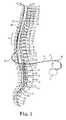
- FIG. 2illustrates the therapy delivery element 14 implanted in the epidural space 30 of a patient in close proximity to the dura, the outer layer that surrounds the spinal cord 32 , to deliver the intended therapeutic effects of spinal cord electrical stimulation.
- the target stimulation sitesmay be anywhere along the spinal cord 32 , such as for example proximate the sacral nerves.
- the implantable pulse generator 12is generally implanted in a surgically-made pocket either in the abdomen or above the buttocks, such as illustrated in FIG. 3 .
- the implantable pulse generator 12may, of course, also be implanted in other locations of the patient's body.
- Use of the extension lead 16facilitates locating the implantable pulse generator 12 away from the lead exit point 34 .
- the extension lead 16serves as a lead adapter if the proximal end 36 of the therapy delivery element 14 is not compatible with the connector 22 of the implantable pulse generator 12 , since different manufacturers use different connectors at the ends of their stimulation leads where the leads are not always compatible with the connector 22 .
- the therapy delivery system 10also may include a clinician programmer 46 and a patient programmer 48 .
- Clinician programmer 46may be a handheld computing device that permits a clinician to program neurostimulation therapy for patient using input keys and a display.
- the clinicianmay specify neurostimulation parameters for use in delivery of neurostimulation therapy.
- Clinician programmer 46supports telemetry (e.g., radio frequency telemetry) with the implantable pulse generator 12 to download neurostimulation parameters and, optionally, upload operational or physiological data stored by implantable pulse generator 12 . In this manner, the clinician may periodically interrogate the implantable pulse generator 12 to evaluate efficacy and, if necessary, modify the stimulation parameters.
- patient programmer 48may be a handheld computing device. Patient programmer 48 may also include a display and input keys to allow the patient to interact with patient programmer 48 and the implantable pulse generator 12 . The patient programmer 48 provides the patient with an interface for control of neurostimulation therapy provided by the implantable pulse generator 12 . For example, the patient may use patient programmer 48 to start, stop, or adjust neurostimulation therapy. In particular, patient programmer 48 may permit the patient to adjust stimulation parameters such as duration, amplitude, pulse width,. and pulse rate, within an adjustment range specified by the clinician via clinician programmer 46 , or select from a library of stored stimulation therapy programs.
- stimulation parameterssuch as duration, amplitude, pulse width,. and pulse rate
- the implantable pulse generator 12 , clinician programmer 46 , and patient programmer 48may communicate via cables or a wireless communication.
- Clinician programmer 46 and patient programmer 48may, for example, communicate via wireless communication with the implantable pulse generator 12 using RF telemetry techniques known in the art.
- Clinician programmer 46 and patient programmer 48also may communicate with each other using any of a variety of local wireless communication techniques, such as RF communication according to the 802.11 or BLUETOOTH® specification sets, infrared communication, e.g., according to the IrDA standard, or other standard or proprietary telemetry protocols.
- FIG. 3also illustrates a general environmental that may benefit from use of a tunneling tool in accordance with an embodiment of the present disclosure.
- the therapy delivery element 14 and/or the extension lead 16is typically routed through a pathway 52 subcutaneously formed along the torso of the patient to a subcutaneous pocket 54 where the implantable pulse generator 12 is located.
- pathway 52subcutaneously formed along the torso of the patient to a subcutaneous pocket 54 where the implantable pulse generator 12 is located.
- “lead” and “lead extension”are used interchangeably, unless content clearly dictates otherwise.
- the therapy delivery elements 14are typically fixed in place near the location selected by the clinician using the present suture anchors 60 .
- the suture anchors 60can be positioned on the therapy delivery element 14 in a wide variety of locations and orientations to accommodate individual anatomical differences and the preferences of the clinician.
- the suture anchors 60may then be affixed to tissue using fasteners, such as for example, one or more sutures, staples, screws, or other fixation devices.
- the tissue to which the suture anchors 60 are affixedmay include subcutaneous fascia layer, bone, or some other type of tissue. Securing the suture anchors 60 to tissue in this manner prevents or reduces the chance that the therapy delivery element 14 will become dislodged or will migrate in an undesired manner.
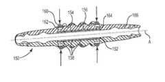
- FIGS. 4 through 6are various views of a suture anchor 70 with a multi-durometer inner sleeve 80 in accordance with an embodiment of the present disclosure.
- Anchor body 72includes primary lumen 74 extending along axis A from first opening 76 A to second opening 76 B (“ 76 ”).
- the anchor body 72is preferably constructed from an elastomeric material, such as for example, medical grade silicone rubber.
- the inner sleeve 80is located in the primary lumen 74 .
- Inner sleeve lumen 82is aligned and co-linear with primary lumen 74 .
- the primary lumen 74 and inner sleeve lumen 82preferably have a larger diameter than outside diameter of therapy delivery element 14 to permit easy positioning of the suture anchor 70 (see FIGS. 7A and 7B ).
- the inner sleeve 80is constructed from at least two different durometer materials.
- Inner layer 84 of the inner sleeve 80is constructed from a softer, more pliable material that easily conforms to the outside diameter of the therapy delivery element 14 to reduce slippage.
- the inner layer 84preferably has a Shore hardness of about 20 to about 35 .
- Outer layer 86 of the inner sleeve 80is a harder, stiffer durometer material that protects the therapy delivery elements 14 from damage due to over-tightening the tie down sutures.
- the outer layer 86preferably has a Shore hardness of about 60 to about 80 .
- the inner and outer layers 84 , 86can be constructed from a variety of biocompatible materials, such as for example silicone rubber, polyurethane, nylon, polyester, or polyimide.
- Reinforcing structure 88is preferably located generally between the inner and outer layers 84 , 86 of the inner sleeve 80 .
- the reinforcing structure 88can be constructed from metal or an implantable grade polymer, such as for example, Dacron.
- the reinforcing structure 88can be configured as a coil, braid, tube, woven component, or a variety of other configurations suitable to protect the therapy delivery element 14 .
- the reinforcing structure 88can be integrated with the inner sleeve 80 using a variety of techniques, such as for example, by overmolding, extruding, or co-extruding the inner and/or outer layers 84 , 86 onto the reinforcing structure 88 .
- Outer surface 90 of the suture body 72includes one or more grooves 92 A, 92 B (“ 92 ”) adapted to receive suture material 94 .
- the grooves 92are oriented at an angle with respect to the reinforcing structure 88 to provide further protection for the therapy delivery element 14 .
- tensioning the suture material 94applies a compressive force 96 on the suture anchor 70 so that inner layer 84 of the inner sleeve 80 contacts the therapy delivery element 14 .
- the low durometer inner layer 84conforms to outer surface of the therapy delivery element 14 .
- Reinforcing structure 88protects the therapy delivery element 14 from over-tightening.
- the compressive force 96is concentrated under the suture material 94 , while the reinforcing structure 88 serves to spread radial compressive force 96 along a greater surface area of the therapy delivery element 14 .
- FIG. 8illustrates an alternate suture anchor 100 with an inner sleeve 102 in accordance with an embodiment of the present disclosure.
- the inner sleeve 102includes inner layer 104 constructed from a softer, more pliable material and outer layer 106 constructed from a harder, stiffer durometer material.
- Reinforcing structure 108is preferably located between the inner and outer layers 104 , 106 .
- Suture material 110is preferably configured as a pre-tied, self-locking compression knot, such as for example, a nail knot.
- a nail knotspreads the radial compression force 112 over a larger surface of the anchor sleeve 100 , increasing frictional engagement between the inner layer 104 and the therapy delivery element 14 .
- the reinforcing structure 108reduces damage to the suture anchor 100 .
- the pre-tied knotremoves variation out of the process by requiring all surgeons to use the same suture material 110 and the same pre-tied knot.
- compression knotrefers to one or more loops of suture material that contracts when one or more distal ends of the suture material are tensioned.
- Self-lockingrefers to a knot that relies on friction between the suture material to substantially maintain a radially compressive force on a structure.
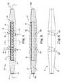
- FIG. 9illustrates an alternate suture anchor 150 with an inner sleeve 152 in accordance with an embodiment of the present disclosure.
- the inner sleeve 152includes inner layer 154 constructed from a softer, more pliable material and outer layer 156 constructed from a harder, stiffer durometer material.
- Reinforcing structure 158is preferably located between the inner and outer layers 154 , 156 .
- Suture material 160is wrapped around compression members 162 .
- the compression members 162are preferably recessed in the compression grooves 164 to retain the suture material 160 in the desired axial location along axis A.
- the compression members 162are optionally attached to anchor body 166 , such as for example, using medical adhesive, liner, mechanical interlocks and the like.
- the compression members 162can be a one-piece structure, such as for example a C-shaped band or a variety of multi-piece structure.
- the compression members 162can be any rigid or semi-rigid material, such as for example, a thermoplastic or thermoset material, stainless steel, Nitinol, or a combination thereof.
- the compression members 162are radiopaque to facilitate medical imaging.
- the compression members 162include an upper portion 170 A and a lower portion 170 B (“ 170 ”) shown in an open configuration 172 .
- the compression members 162are preferably discontinuous.
- the compression members 162include compression gaps 174 .
- tension force 176is applied to distal ends 178 of the suture material 160 , which generates radial compression force 180 that is applied to the compression members 162 .
- the upper and lower portions 170 of the compression members 162are displaced radially inward by the force 180 until edges engage in compressed configuration 182 .
- the discontinuous nature of the compression members 162permits the compression gaps 174 to be closed to form the compressed configuration 182 .
- Embodiments of the suture anchor with the present compression members 182can be used with or without the reinforcing structure in the inner sleeve 152 .
- the suture anchorcan be infused with medical adhesive in accordance with an embodiment of the present disclosure.
- the medical adhesiveis preferably delivered after the anchor is positioned in the desired location along the therapy delivery element 14 .
- the medical adhesivecan be any type of biocompatible medical-grade adhesive.
- Such medical adhesiveincludes polyurethane and/or silicone adhesives.
- One exampleis Room Temperature Vulcanization (RTV) silicone adhesive which cures at room temperature. This type of adhesive is generally kept under pressure to prevent it from curing until ready to use. When pressure is removed (e.g., the adhesive is dispensed from the tube) the adhesive will set up, becoming solid, or semi-solid in nature.
- RTVRoom Temperature Vulcanization
- Another exampleis a silicone or polyurethane adhesive that cures when exposed to UV or visible light, as is available from the Dymax Corporation.
- FIG. 11is a flow diagram of a method of implanting a neurostimulation system within a living body.
- the methodincludes the steps of implanting an implantable pulse generator within the living body ( 200 ). Electrodes at a distal end of a therapy delivery element are positioned at a target location within the living body ( 202 ). A proximal end of the therapy delivery element is inserted into a lumen in the present suture anchor ( 204 ). The suture anchor is slide along the therapy delivery element to a desired location ( 206 ). The surgeon then attaches the suture anchor to the patient's tissue, such as for example, using staples or external sutures wrapped around central ribs of the suture anchor ( 208 ).
- Suture material wrapped around the suture anchoris tensioned to apply a radial compressive force until inner layer of inner sleeve contacts the therapy delivery element ( 210 ).
- Outer layer of the inner sleeve and the reinforcing structurespreads the radial compressive force along a greater surface area of the therapy delivery element ( 212 ).
- the proximal end of the therapy delivery elementis electrically coupled to the implantable pulse generator ( 214 ).
Landscapes
- Health & Medical Sciences (AREA)
- Life Sciences & Earth Sciences (AREA)
- Heart & Thoracic Surgery (AREA)
- Animal Behavior & Ethology (AREA)
- Veterinary Medicine (AREA)
- Public Health (AREA)
- Engineering & Computer Science (AREA)
- Biomedical Technology (AREA)
- Nuclear Medicine, Radiotherapy & Molecular Imaging (AREA)
- General Health & Medical Sciences (AREA)
- Surgery (AREA)
- Radiology & Medical Imaging (AREA)
- Cardiology (AREA)
- Neurology (AREA)
- Orthopedic Medicine & Surgery (AREA)
- Neurosurgery (AREA)
- Rheumatology (AREA)
- Medical Informatics (AREA)
- Molecular Biology (AREA)
- Prostheses (AREA)
Abstract
Description
Claims (18)
Priority Applications (4)
| Application Number | Priority Date | Filing Date | Title |
|---|---|---|---|
| US13/164,942US8676341B2 (en) | 2011-06-21 | 2011-06-21 | Multi durometer reinforced suture sleeve |
| US13/445,204US8688232B2 (en) | 2011-06-21 | 2012-04-12 | Multi-durometer reinforced suture sleeve |
| US14/083,591US8934991B2 (en) | 2011-06-21 | 2013-11-19 | Multi-durometer reinforced suture sleeve |
| US14/171,995US8886338B2 (en) | 2011-06-21 | 2014-02-04 | Multi-durometer reinforced suture sleeve |
Applications Claiming Priority (1)
| Application Number | Priority Date | Filing Date | Title |
|---|---|---|---|
| US13/164,942US8676341B2 (en) | 2011-06-21 | 2011-06-21 | Multi durometer reinforced suture sleeve |
Related Child Applications (2)
| Application Number | Title | Priority Date | Filing Date |
|---|---|---|---|
| US13/445,204Continuation-In-PartUS8688232B2 (en) | 2011-06-21 | 2012-04-12 | Multi-durometer reinforced suture sleeve |
| US14/083,591ContinuationUS8934991B2 (en) | 2011-06-21 | 2013-11-19 | Multi-durometer reinforced suture sleeve |
Publications (2)
| Publication Number | Publication Date |
|---|---|
| US20120330354A1 US20120330354A1 (en) | 2012-12-27 |
| US8676341B2true US8676341B2 (en) | 2014-03-18 |
Family
ID=47362559
Family Applications (2)
| Application Number | Title | Priority Date | Filing Date |
|---|---|---|---|
| US13/164,942Active2031-12-04US8676341B2 (en) | 2011-06-21 | 2011-06-21 | Multi durometer reinforced suture sleeve |
| US14/083,591ActiveUS8934991B2 (en) | 2011-06-21 | 2013-11-19 | Multi-durometer reinforced suture sleeve |
Family Applications After (1)
| Application Number | Title | Priority Date | Filing Date |
|---|---|---|---|
| US14/083,591ActiveUS8934991B2 (en) | 2011-06-21 | 2013-11-19 | Multi-durometer reinforced suture sleeve |
Country Status (1)
| Country | Link |
|---|---|
| US (2) | US8676341B2 (en) |
Cited By (8)
| Publication number | Priority date | Publication date | Assignee | Title |
|---|---|---|---|---|
| US20150066121A1 (en)* | 2013-08-30 | 2015-03-05 | Boston Scientific Neuromodulation Corporation | Systems and methods for making and using lead anchors for leads of electrical stimulation systems |
| US20170246454A1 (en)* | 2016-02-29 | 2017-08-31 | Boston Scientific Neuromodulation Corporation | Lead anchor for an electrical stimulation system |
| US11116975B2 (en) | 2015-11-09 | 2021-09-14 | Bluewind Medical Ltd. | Optimization of application of current |
| US11213685B2 (en) | 2017-06-13 | 2022-01-04 | Bluewind Medical Ltd. | Antenna configuration |
| US11278719B2 (en) | 2012-12-06 | 2022-03-22 | Bluewind Medical Ltd. | Delivery of implantable neurostimulators |
| US11400299B1 (en) | 2021-09-14 | 2022-08-02 | Rainbow Medical Ltd. | Flexible antenna for stimulator |
| US11439833B2 (en) | 2016-11-23 | 2022-09-13 | Bluewind Medical Ltd. | Implant-delivery tool |
| US11648410B2 (en) | 2012-01-26 | 2023-05-16 | Bluewind Medical Ltd. | Wireless neurostimulators |
Families Citing this family (20)
| Publication number | Priority date | Publication date | Assignee | Title |
|---|---|---|---|---|
| US8688232B2 (en) | 2011-06-21 | 2014-04-01 | Greatbatch Ltd. | Multi-durometer reinforced suture sleeve |
| US8676341B2 (en) | 2011-06-21 | 2014-03-18 | Greatbatch Ltd. | Multi durometer reinforced suture sleeve |
| US8535339B2 (en) | 2011-12-18 | 2013-09-17 | Via Surgical Ltd. | Apparatus and method for suturing |
| US9888913B2 (en) | 2012-05-31 | 2018-02-13 | Via Surgical Ltd. | Variable depth surgical fixation |
| WO2014070680A1 (en)* | 2012-10-29 | 2014-05-08 | Cardiac Pacemakers, Inc. | Suture sleeves having exterior surface tear resistance |
| US9486622B2 (en) | 2012-11-08 | 2016-11-08 | Cardiac Pacemakers, Inc. | Fixation and strain relief element for temporary therapy delivery device |
| EP3492035B1 (en) | 2014-02-06 | 2022-10-05 | St. Jude Medical, Cardiology Division, Inc. | Elongate medical device including chamfered ring electrode and variable shaft |
| JP6661600B2 (en)* | 2014-07-18 | 2020-03-11 | エシコン・インコーポレイテッドEthicon, Inc. | Mechanical retraction by mooring for lung volume reduction |
| AU2015301398B2 (en)* | 2014-08-15 | 2020-05-21 | Axonics Modulation Technologies, Inc. | Implantable lead affixation structure for nerve stimulation to alleviate bladder dysfunction and other indications |
| US11097109B2 (en) | 2014-11-24 | 2021-08-24 | AtaCor Medical, Inc. | Cardiac pacing sensing and control |
| ES2821006T3 (en) | 2015-04-23 | 2021-04-23 | Via Surgical Ltd | Surgical Fastener Locking and Delivery Mechanism |
| EP3297718A1 (en) | 2015-05-20 | 2018-03-28 | Cardiac Pacemakers, Inc. | Fully integrated lead stabilizer for medical electrical leads and methods of attachment |
| AU2016344019B2 (en) | 2015-10-30 | 2021-07-15 | New York Society For The Relief Of The Ruptured And Crippled, Maintaining The Hospital For Special Surgery | Suture sleeve patch and methods of delivery within an existing arthroscopic workflow |
| WO2019165108A1 (en) | 2018-02-22 | 2019-08-29 | Axonics Modulation Technologies, Inc. | Neurostimulation leads for trial nerve stimulation and methods of use |
| CN108830783B (en) | 2018-05-31 | 2021-07-02 | 北京市商汤科技开发有限公司 | Image processing method and device and computer storage medium |
| US11565105B2 (en)* | 2018-10-05 | 2023-01-31 | Biotronik Se & Co. Kg | Lead anchor for a neuromodulation lead |
| US12420103B1 (en) | 2020-08-20 | 2025-09-23 | Axonics, Inc. | Neurostimulation leads with reduced current leakage |
| US12433738B2 (en) | 2021-03-22 | 2025-10-07 | Drew Miller | Tendon surgery nail knot systems and methods |
| CA3240237A1 (en)* | 2021-11-24 | 2023-06-01 | AtaCor Medical, Inc. | Implantable electrical leads and associated delivery and control systems |
| WO2024179815A1 (en)* | 2023-03-02 | 2024-09-06 | Biotronik Se & Co. Kg | Fixation sleeve and assembly comprising such sleeve |
Citations (31)
| Publication number | Priority date | Publication date | Assignee | Title |
|---|---|---|---|---|
| US4516584A (en) | 1983-01-07 | 1985-05-14 | Cordis Corporation | Suture collar |
| US4553961A (en) | 1984-04-18 | 1985-11-19 | Cordis Corporation | Suture sleeve with structure for enhancing pacing lead gripping |
| US4672979A (en) | 1986-01-30 | 1987-06-16 | Cordis Corporation | Suture sleeve assembly |
| US5273053A (en) | 1992-11-02 | 1993-12-28 | Medtronic, Inc. | Suture sleeve with lead locking device |
| US5376108A (en) | 1993-05-20 | 1994-12-27 | Telectronics Pacing Systems, Inc. | Electrode lead anchoring apparatus and method employing dual suture collars |
| US5484445A (en) | 1993-10-12 | 1996-01-16 | Medtronic, Inc. | Sacral lead anchoring system |
| US5584874A (en) | 1995-04-28 | 1996-12-17 | Medtronic, Inc. | Medical electrical lead having improved anchoring sleeve |
| US5690676A (en) | 1990-07-13 | 1997-11-25 | Smith & Nephew, Inc. | Suture anchor and drive assembly |
| EP0865799A2 (en) | 1996-12-26 | 1998-09-23 | JOHNSON & JOHNSON MEDICAL, INC. | Adjustable securing wings |
| US5843146A (en) | 1997-04-30 | 1998-12-01 | Medtronic Incorporated | Adjustable medical lead anchor |
| US6134477A (en) | 1999-04-30 | 2000-10-17 | Medtronic, Inc. | Adjustable medical lead fixation system |
| US6261021B1 (en)* | 1999-11-16 | 2001-07-17 | Acco Brands, Inc. | Binder insert having a clip |
| US6473654B1 (en) | 2000-03-08 | 2002-10-29 | Advanced Bionics Corporation | Lead anchor |
| US6685728B2 (en) | 2002-01-25 | 2004-02-03 | Stryker Endoscopy | Threaded suture anchor and method of use |
| US20040199234A1 (en)* | 2003-04-07 | 2004-10-07 | Cardiac Pacemakers, Inc. | Extra strength suture sleeve |
| US6901287B2 (en) | 2001-02-09 | 2005-05-31 | Medtronic, Inc. | Implantable therapy delivery element adjustable anchor |
| US6932834B2 (en) | 2002-06-27 | 2005-08-23 | Ethicon, Inc. | Suture anchor |
| US20070239242A1 (en) | 2006-04-06 | 2007-10-11 | Graubert Daniel A | Apparatus and method for anchoring an implanted lead |
| US7390329B2 (en) | 2004-05-07 | 2008-06-24 | Usgi Medical, Inc. | Methods for grasping and cinching tissue anchors |
| US20080243151A1 (en) | 2004-04-12 | 2008-10-02 | Binmoeller Kenneth F | Luminal Structure Anchoring Devices and Methods |
| US20090125059A1 (en)* | 2007-11-09 | 2009-05-14 | Verzal Kevin E | Compression member suture sleeve |
| US20090132042A1 (en)* | 2007-10-17 | 2009-05-21 | Hetke Jamille F | Implantable device including a resorbable carrier |
| US20090248054A1 (en) | 2008-03-27 | 2009-10-01 | Medtronic, Inc. | Anchor and anchor deployment apparatus |
| US20090287187A1 (en)* | 2008-05-07 | 2009-11-19 | Guided Delivery Systems Inc. | Deflectable guide |
| US20100030311A1 (en) | 2008-07-31 | 2010-02-04 | Lazeroms Markus J C | Subcutaneously implantable lead including distal fixation mechanism |
| US20100049277A1 (en) | 2005-03-11 | 2010-02-25 | Medtronic, Inc. | Implantable neurostimulator device |
| US20100076487A1 (en) | 2008-09-23 | 2010-03-25 | Ilahi Omer A | Kit Containing Combination Absorbable Staple and Non-absorbable Suture, And Method Of Using Same |
| US20100174240A1 (en) | 2009-01-06 | 2010-07-08 | Medtronic, Inc. | Anchor having fill port for use with an implantable therapy delivery element |
| US20100274336A1 (en) | 2009-04-27 | 2010-10-28 | Boston Scientific Neuromodulation Corporation | Torque lock anchor and methods and devices using the anchor |
| US7824421B2 (en) | 2005-03-30 | 2010-11-02 | Ethicon Endo-Surgery, Inc. | Anchors for use in anastomotic procedures |
| US7831313B2 (en) | 2005-08-26 | 2010-11-09 | Boston Scientific Neuromodulation Corporation | Lead anchor for implantable stimulation devices and methods of manufacture and use |
Family Cites Families (3)
| Publication number | Priority date | Publication date | Assignee | Title |
|---|---|---|---|---|
| US20060264803A1 (en)* | 2005-04-26 | 2006-11-23 | Cook Vascular Incorporated | Suture collar |
| US20080161890A1 (en) | 2007-01-03 | 2008-07-03 | Boston Scientific Scimed, Inc. | Methods, systems, and apparatuses for protecting esophageal tissue during ablation |
| US8676341B2 (en) | 2011-06-21 | 2014-03-18 | Greatbatch Ltd. | Multi durometer reinforced suture sleeve |
- 2011
- 2011-06-21USUS13/164,942patent/US8676341B2/enactiveActive
- 2013
- 2013-11-19USUS14/083,591patent/US8934991B2/enactiveActive
Patent Citations (34)
| Publication number | Priority date | Publication date | Assignee | Title |
|---|---|---|---|---|
| US4516584A (en) | 1983-01-07 | 1985-05-14 | Cordis Corporation | Suture collar |
| US4553961A (en) | 1984-04-18 | 1985-11-19 | Cordis Corporation | Suture sleeve with structure for enhancing pacing lead gripping |
| US4672979A (en) | 1986-01-30 | 1987-06-16 | Cordis Corporation | Suture sleeve assembly |
| US5690676A (en) | 1990-07-13 | 1997-11-25 | Smith & Nephew, Inc. | Suture anchor and drive assembly |
| US5273053A (en) | 1992-11-02 | 1993-12-28 | Medtronic, Inc. | Suture sleeve with lead locking device |
| US5376108A (en) | 1993-05-20 | 1994-12-27 | Telectronics Pacing Systems, Inc. | Electrode lead anchoring apparatus and method employing dual suture collars |
| US5484445A (en) | 1993-10-12 | 1996-01-16 | Medtronic, Inc. | Sacral lead anchoring system |
| US5584874A (en) | 1995-04-28 | 1996-12-17 | Medtronic, Inc. | Medical electrical lead having improved anchoring sleeve |
| EP0865799A2 (en) | 1996-12-26 | 1998-09-23 | JOHNSON & JOHNSON MEDICAL, INC. | Adjustable securing wings |
| US5814021A (en) | 1996-12-26 | 1998-09-29 | Johnson & Johnson Medical, Inc. | Adjustable securing wings |
| US5843146A (en) | 1997-04-30 | 1998-12-01 | Medtronic Incorporated | Adjustable medical lead anchor |
| US6134477A (en) | 1999-04-30 | 2000-10-17 | Medtronic, Inc. | Adjustable medical lead fixation system |
| US6261021B1 (en)* | 1999-11-16 | 2001-07-17 | Acco Brands, Inc. | Binder insert having a clip |
| US6473654B1 (en) | 2000-03-08 | 2002-10-29 | Advanced Bionics Corporation | Lead anchor |
| US6901287B2 (en) | 2001-02-09 | 2005-05-31 | Medtronic, Inc. | Implantable therapy delivery element adjustable anchor |
| US6685728B2 (en) | 2002-01-25 | 2004-02-03 | Stryker Endoscopy | Threaded suture anchor and method of use |
| US6932834B2 (en) | 2002-06-27 | 2005-08-23 | Ethicon, Inc. | Suture anchor |
| US20040199234A1 (en)* | 2003-04-07 | 2004-10-07 | Cardiac Pacemakers, Inc. | Extra strength suture sleeve |
| US20080243151A1 (en) | 2004-04-12 | 2008-10-02 | Binmoeller Kenneth F | Luminal Structure Anchoring Devices and Methods |
| US7390329B2 (en) | 2004-05-07 | 2008-06-24 | Usgi Medical, Inc. | Methods for grasping and cinching tissue anchors |
| US20080177304A1 (en)* | 2004-09-29 | 2008-07-24 | Usgi Medical, Inc. | Apparatus for grasping and cinching tissue anchors |
| US20100049277A1 (en) | 2005-03-11 | 2010-02-25 | Medtronic, Inc. | Implantable neurostimulator device |
| US7824421B2 (en) | 2005-03-30 | 2010-11-02 | Ethicon Endo-Surgery, Inc. | Anchors for use in anastomotic procedures |
| US7831313B2 (en) | 2005-08-26 | 2010-11-09 | Boston Scientific Neuromodulation Corporation | Lead anchor for implantable stimulation devices and methods of manufacture and use |
| US20070239242A1 (en) | 2006-04-06 | 2007-10-11 | Graubert Daniel A | Apparatus and method for anchoring an implanted lead |
| US20090132042A1 (en)* | 2007-10-17 | 2009-05-21 | Hetke Jamille F | Implantable device including a resorbable carrier |
| US20090125059A1 (en)* | 2007-11-09 | 2009-05-14 | Verzal Kevin E | Compression member suture sleeve |
| US8126569B2 (en) | 2007-11-09 | 2012-02-28 | Cardiac Pacemakers, Inc. | Compression control lead anchoring device |
| US20090248054A1 (en) | 2008-03-27 | 2009-10-01 | Medtronic, Inc. | Anchor and anchor deployment apparatus |
| US20090287187A1 (en)* | 2008-05-07 | 2009-11-19 | Guided Delivery Systems Inc. | Deflectable guide |
| US20100030311A1 (en) | 2008-07-31 | 2010-02-04 | Lazeroms Markus J C | Subcutaneously implantable lead including distal fixation mechanism |
| US20100076487A1 (en) | 2008-09-23 | 2010-03-25 | Ilahi Omer A | Kit Containing Combination Absorbable Staple and Non-absorbable Suture, And Method Of Using Same |
| US20100174240A1 (en) | 2009-01-06 | 2010-07-08 | Medtronic, Inc. | Anchor having fill port for use with an implantable therapy delivery element |
| US20100274336A1 (en) | 2009-04-27 | 2010-10-28 | Boston Scientific Neuromodulation Corporation | Torque lock anchor and methods and devices using the anchor |
Cited By (14)
| Publication number | Priority date | Publication date | Assignee | Title |
|---|---|---|---|---|
| US11648410B2 (en) | 2012-01-26 | 2023-05-16 | Bluewind Medical Ltd. | Wireless neurostimulators |
| US12059571B2 (en) | 2012-01-26 | 2024-08-13 | Bluewind Medical Ltd | Wireless neurostimulators |
| US11464966B2 (en) | 2012-12-06 | 2022-10-11 | Bluewind Medical Ltd. | Delivery of implantable neurostimulators |
| US11278719B2 (en) | 2012-12-06 | 2022-03-22 | Bluewind Medical Ltd. | Delivery of implantable neurostimulators |
| US20150066121A1 (en)* | 2013-08-30 | 2015-03-05 | Boston Scientific Neuromodulation Corporation | Systems and methods for making and using lead anchors for leads of electrical stimulation systems |
| US9095701B2 (en)* | 2013-08-30 | 2015-08-04 | Boston Scientific Neuromodulation Corporation | Systems and methods for making and using lead anchors for leads of electrical stimulation systems |
| US11116975B2 (en) | 2015-11-09 | 2021-09-14 | Bluewind Medical Ltd. | Optimization of application of current |
| US11612747B2 (en) | 2015-11-09 | 2023-03-28 | Bluewind Medical Ltd. | Optimization of application of current |
| US10071242B2 (en)* | 2016-02-29 | 2018-09-11 | Boston Scientific Neuromodulation Corporation | Lead anchor for an electrical stimulation system |
| US20170246454A1 (en)* | 2016-02-29 | 2017-08-31 | Boston Scientific Neuromodulation Corporation | Lead anchor for an electrical stimulation system |
| US11439833B2 (en) | 2016-11-23 | 2022-09-13 | Bluewind Medical Ltd. | Implant-delivery tool |
| US11213685B2 (en) | 2017-06-13 | 2022-01-04 | Bluewind Medical Ltd. | Antenna configuration |
| US11951316B2 (en) | 2017-06-13 | 2024-04-09 | Bluewind Medical Ltd. | Antenna configuration |
| US11400299B1 (en) | 2021-09-14 | 2022-08-02 | Rainbow Medical Ltd. | Flexible antenna for stimulator |
Also Published As
| Publication number | Publication date |
|---|---|
| US20120330354A1 (en) | 2012-12-27 |
| US8934991B2 (en) | 2015-01-13 |
| US20140081365A1 (en) | 2014-03-20 |
Similar Documents
| Publication | Publication Date | Title |
|---|---|---|
| US8934991B2 (en) | Multi-durometer reinforced suture sleeve | |
| US8886338B2 (en) | Multi-durometer reinforced suture sleeve | |
| US9026227B2 (en) | Anchor sleeve for implantable lead | |
| US8483845B2 (en) | Anchor for implantable medical device | |
| US8437846B2 (en) | Pre-sutured anchor for implantable leads | |
| US11013911B2 (en) | Lead positioning and finned fixation system | |
| US8676347B2 (en) | Braided lead with embedded fixation structures | |
| US9095700B2 (en) | Lead positioning and fixation system | |
| US9320888B2 (en) | Adjustable wire length stylet handle | |
| US11833359B2 (en) | Bulkhead anchor for medical device leads | |
| US9775985B2 (en) | Braided lead with embedded fixation structures | |
| US12280262B2 (en) | Slip ring anchor |
Legal Events
| Date | Code | Title | Description |
|---|---|---|---|
| AS | Assignment | Owner name:GREATBATCH LTD., NEW YORK Free format text:ASSIGNMENT OF ASSIGNORS INTEREST;ASSIGNORS:KANE, LAWRENCE;SWOYER, JOHN;REEL/FRAME:026470/0948 Effective date:20110603 | |
| STCF | Information on status: patent grant | Free format text:PATENTED CASE | |
| AS | Assignment | Owner name:MANUFACTURERS AND TRADERS TRUST COMPANY, NEW YORK Free format text:SECURITY INTEREST;ASSIGNORS:GREATBATCH, INC.;GREATBATCH LTD.;ELECTROCHEM SOLUTIONS, INC.;AND OTHERS;REEL/FRAME:036980/0482 Effective date:20151027 | |
| AS | Assignment | Owner name:QIG GROUP, LLC, NEW YORK Free format text:ASSIGNMENT OF ASSIGNORS INTEREST;ASSIGNOR:GREATBATCH LTD.;REEL/FRAME:037810/0051 Effective date:20160212 | |
| AS | Assignment | Owner name:NUVECTRA CORPORATION, TEXAS Free format text:CHANGE OF NAME;ASSIGNOR:QIG GROUP, LLC;REEL/FRAME:038455/0153 Effective date:20160314 | |
| AS | Assignment | Owner name:QIG GROUP LLC, TEXAS Free format text:RELEASE BY SECURED PARTY;ASSIGNOR:MANUFACTURERS AND TRADERS TRUST COMPANY;REEL/FRAME:039132/0773 Effective date:20160418 Owner name:MICRO POWER ELECTRONICS, INC., OREGON Free format text:RELEASE BY SECURED PARTY;ASSIGNOR:MANUFACTURERS AND TRADERS TRUST COMPANY;REEL/FRAME:039132/0773 Effective date:20160418 Owner name:GREATBATCH INC., NEW YORK Free format text:RELEASE BY SECURED PARTY;ASSIGNOR:MANUFACTURERS AND TRADERS TRUST COMPANY;REEL/FRAME:039132/0773 Effective date:20160418 Owner name:NEURONEXUS TECHNOLOGIES, INC., MICHIGAN Free format text:RELEASE BY SECURED PARTY;ASSIGNOR:MANUFACTURERS AND TRADERS TRUST COMPANY;REEL/FRAME:039132/0773 Effective date:20160418 Owner name:GREATBATCH LTD., NEW YORK Free format text:RELEASE BY SECURED PARTY;ASSIGNOR:MANUFACTURERS AND TRADERS TRUST COMPANY;REEL/FRAME:039132/0773 Effective date:20160418 Owner name:ELECTROCHEM SOLUTIONS, INC., NEW YORK Free format text:RELEASE BY SECURED PARTY;ASSIGNOR:MANUFACTURERS AND TRADERS TRUST COMPANY;REEL/FRAME:039132/0773 Effective date:20160418 | |
| FPAY | Fee payment | Year of fee payment:4 | |
| AS | Assignment | Owner name:CIRTEC MEDICAL CORP., MINNESOTA Free format text:ASSIGNMENT OF ASSIGNORS INTEREST;ASSIGNOR:NUVECTRA CORPORATION;REEL/FRAME:052185/0680 Effective date:20200317 | |
| MAFP | Maintenance fee payment | Free format text:PAYMENT OF MAINTENANCE FEE, 8TH YEAR, LARGE ENTITY (ORIGINAL EVENT CODE: M1552); ENTITY STATUS OF PATENT OWNER: LARGE ENTITY Year of fee payment:8 | |
| AS | Assignment | Owner name:MICRO POWER ELECTRONICS, INC., NEW YORK Free format text:RELEASE BY SECURED PARTY;ASSIGNOR:MANUFACTURERS AND TRADERS TRUST COMPANY (AS ADMINISTRATIVE AGENT);REEL/FRAME:060938/0069 Effective date:20210903 Owner name:PRECIMED INC., NEW YORK Free format text:RELEASE BY SECURED PARTY;ASSIGNOR:MANUFACTURERS AND TRADERS TRUST COMPANY (AS ADMINISTRATIVE AGENT);REEL/FRAME:060938/0069 Effective date:20210903 Owner name:GREATBATCH-GLOBE TOOL, INC., NEW YORK Free format text:RELEASE BY SECURED PARTY;ASSIGNOR:MANUFACTURERS AND TRADERS TRUST COMPANY (AS ADMINISTRATIVE AGENT);REEL/FRAME:060938/0069 Effective date:20210903 Owner name:NEURONEXUS TECHNOLOGIES, INC., NEW YORK Free format text:RELEASE BY SECURED PARTY;ASSIGNOR:MANUFACTURERS AND TRADERS TRUST COMPANY (AS ADMINISTRATIVE AGENT);REEL/FRAME:060938/0069 Effective date:20210903 Owner name:ELECTROCHEM SOLUTIONS, INC., NEW YORK Free format text:RELEASE BY SECURED PARTY;ASSIGNOR:MANUFACTURERS AND TRADERS TRUST COMPANY (AS ADMINISTRATIVE AGENT);REEL/FRAME:060938/0069 Effective date:20210903 Owner name:GREATBATCH LTD., NEW YORK Free format text:RELEASE BY SECURED PARTY;ASSIGNOR:MANUFACTURERS AND TRADERS TRUST COMPANY (AS ADMINISTRATIVE AGENT);REEL/FRAME:060938/0069 Effective date:20210903 Owner name:GREATBATCH, INC., NEW YORK Free format text:RELEASE BY SECURED PARTY;ASSIGNOR:MANUFACTURERS AND TRADERS TRUST COMPANY (AS ADMINISTRATIVE AGENT);REEL/FRAME:060938/0069 Effective date:20210903 | |
| AS | Assignment | Owner name:MICRO POWER ELECTRONICS, INC., NEW YORK Free format text:RELEASE BY SECURED PARTY;ASSIGNOR:MANUFACTURERS AND TRADERS TRUST COMPANY (AS ADMINISTRATIVE AGENT);REEL/FRAME:061659/0858 Effective date:20210903 Owner name:PRECIMED INC., NEW YORK Free format text:RELEASE BY SECURED PARTY;ASSIGNOR:MANUFACTURERS AND TRADERS TRUST COMPANY (AS ADMINISTRATIVE AGENT);REEL/FRAME:061659/0858 Effective date:20210903 Owner name:GREATBATCH-GLOBE TOOL, INC., NEW YORK Free format text:RELEASE BY SECURED PARTY;ASSIGNOR:MANUFACTURERS AND TRADERS TRUST COMPANY (AS ADMINISTRATIVE AGENT);REEL/FRAME:061659/0858 Effective date:20210903 Owner name:NEURONEXUS TECHNOLOGIES, INC., NEW YORK Free format text:RELEASE BY SECURED PARTY;ASSIGNOR:MANUFACTURERS AND TRADERS TRUST COMPANY (AS ADMINISTRATIVE AGENT);REEL/FRAME:061659/0858 Effective date:20210903 Owner name:ELECTROCHEM SOLUTIONS, INC., NEW YORK Free format text:RELEASE BY SECURED PARTY;ASSIGNOR:MANUFACTURERS AND TRADERS TRUST COMPANY (AS ADMINISTRATIVE AGENT);REEL/FRAME:061659/0858 Effective date:20210903 Owner name:GREATBATCH LTD., NEW YORK Free format text:RELEASE BY SECURED PARTY;ASSIGNOR:MANUFACTURERS AND TRADERS TRUST COMPANY (AS ADMINISTRATIVE AGENT);REEL/FRAME:061659/0858 Effective date:20210903 Owner name:GREATBATCH, INC., NEW YORK Free format text:RELEASE BY SECURED PARTY;ASSIGNOR:MANUFACTURERS AND TRADERS TRUST COMPANY (AS ADMINISTRATIVE AGENT);REEL/FRAME:061659/0858 Effective date:20210903 | |
| AS | Assignment | Owner name:BMO HARRIS BANK N.A., AS COLLATERAL AGENT, ILLINOIS Free format text:PATENT SECURITY AGREEMENT;ASSIGNOR:CIRTEC MEDICAL CORP.;REEL/FRAME:062559/0098 Effective date:20230130 | |
| MAFP | Maintenance fee payment | Free format text:PAYMENT OF MAINTENANCE FEE, 12TH YEAR, LARGE ENTITY (ORIGINAL EVENT CODE: M1553); ENTITY STATUS OF PATENT OWNER: LARGE ENTITY Year of fee payment:12 |