US8676197B2 - System, method, and device to control wireless communications - Google Patents
System, method, and device to control wireless communicationsDownload PDFInfo
- Publication number
- US8676197B2 US8676197B2US11/955,017US95501707AUS8676197B2US 8676197 B2US8676197 B2US 8676197B2US 95501707 AUS95501707 AUS 95501707AUS 8676197 B2US8676197 B2US 8676197B2
- Authority
- US
- United States
- Prior art keywords
- base station
- communication device
- mobile
- mimicking
- communications
- Prior art date
- Legal status (The legal status is an assumption and is not a legal conclusion. Google has not performed a legal analysis and makes no representation as to the accuracy of the status listed.)
- Active - Reinstated, expires
Links
Images


Classifications
- H—ELECTRICITY
- H04—ELECTRIC COMMUNICATION TECHNIQUE
- H04K—SECRET COMMUNICATION; JAMMING OF COMMUNICATION
- H04K3/00—Jamming of communication; Counter-measures
- H04K3/80—Jamming or countermeasure characterized by its function
- H04K3/92—Jamming or countermeasure characterized by its function related to allowing or preventing remote control
- H—ELECTRICITY
- H04—ELECTRIC COMMUNICATION TECHNIQUE
- H04B—TRANSMISSION
- H04B7/00—Radio transmission systems, i.e. using radiation field
- H04B7/14—Relay systems
- H04B7/15—Active relay systems
- H04B7/185—Space-based or airborne stations; Stations for satellite systems
- H04B7/1853—Satellite systems for providing telephony service to a mobile station, i.e. mobile satellite service
- H—ELECTRICITY
- H04—ELECTRIC COMMUNICATION TECHNIQUE
- H04L—TRANSMISSION OF DIGITAL INFORMATION, e.g. TELEGRAPHIC COMMUNICATION
- H04L63/00—Network architectures or network communication protocols for network security
- H04L63/30—Network architectures or network communication protocols for network security for supporting lawful interception, monitoring or retaining of communications or communication related information
- H—ELECTRICITY
- H04—ELECTRIC COMMUNICATION TECHNIQUE
- H04W—WIRELESS COMMUNICATION NETWORKS
- H04W40/00—Communication routing or communication path finding
- H04W40/02—Communication route or path selection, e.g. power-based or shortest path routing
- H—ELECTRICITY
- H04—ELECTRIC COMMUNICATION TECHNIQUE
- H04W—WIRELESS COMMUNICATION NETWORKS
- H04W48/00—Access restriction; Network selection; Access point selection
- H04W48/02—Access restriction performed under specific conditions
- H04W48/04—Access restriction performed under specific conditions based on user or terminal location or mobility data, e.g. moving direction, speed
- H—ELECTRICITY
- H04—ELECTRIC COMMUNICATION TECHNIQUE
- H04W—WIRELESS COMMUNICATION NETWORKS
- H04W88/00—Devices specially adapted for wireless communication networks, e.g. terminals, base stations or access point devices
- H04W88/08—Access point devices
Definitions
- the present disclosurerelates generally to controlling wireless communications.
- Improvised explosive deviceshave caused many deaths in certain regions of the world. IEDs may be made using commercially available supplies. For example, some IEDs may use a mobile communications device, such as a cellular telephone or pager, as a triggering device. The mobile communications device may be connected to a detonator of the IED. Upon receiving a particular signal, such as an incoming call signal, the mobile communications device may cause the detonation of the IED.
- a mobile communications devicesuch as a cellular telephone or pager
- the mobile communications devicemay be connected to a detonator of the IED. Upon receiving a particular signal, such as an incoming call signal, the mobile communications device may cause the detonation of the IED.
- Jamming mobile communications of mobile communication devices used in IEDsmay be difficult and expensive for multi-channel commercial wireless systems, such as Global System for Mobile Communication (GSM) and Code Division Multiple Access (CDMA) systems. Accordingly, there exists a need for an improved method and system of controlling wireless communications.
- GSMGlobal System for Mobile Communication
- CDMACode Division Multiple Access
- FIG. 1is a view of a distributed mobile architecture server having a first illustrative form factor
- FIG. 2is a view of an alternative embodiment of a distributed mobile architecture server having a second illustrative form factor
- FIG. 3is a diagram of another alternative embodiment of a distributed mobile architecture server having a third illustrative form factor
- FIG. 4is a diagram of a distributed and associative communication system
- FIG. 5is a block diagram of a distributed mobile architecture server
- FIG. 6is a flow chart to illustrate operating logic of a distributed mobile architecture server
- FIG. 7is a flow chart to illustrate call hand-off logic of a distributed mobile architecture server
- FIG. 8is a flow chart to illustrate group call logic of a distributed mobile architecture server
- FIG. 9is a diagram of an exemplary communication system in which a distributed mobile architecture server can be incorporated.
- FIG. 10is a diagram of a wireless local loop communication system in which a distributed mobile architecture server can be incorporated;
- FIG. 11is a diagram of plural wireless local loop communication systems connected to the public switched telephone network via a single back-haul connection;
- FIG. 12is a diagram of a communication system in which a distributed mobile architecture server can be deployed to extend an existing cellular network
- FIG. 13is a diagram of a communication system in which a distributed mobile architecture server can be deployed to cover urban fringe around an existing network;
- FIG. 14is a diagram of a communication system in which a single distributed mobile architecture server can be connected to plural base transceiver stations and can provide a single backhaul to the public switched telephone network;
- FIG. 15is a diagram of an in-building communication system in which a distributed mobile architecture server can be deployed
- FIG. 16is a diagram of a mobile in-field communication system in which multiple distributed mobile architecture servers can be deployed via multiple vehicles;
- FIG. 17is a diagram of a communication system in which a distributed mobile architecture server can utilize a satellite connection as a backhaul connection;
- FIG. 18is a diagram of a communication system in which a distributed mobile architecture server can receive multiple backhaul signals via multiple satellite signals;
- FIG. 19is a diagram of a communication system in which a single distributed mobile architecture server can be connected to multiple base transceiver stations;
- FIG. 20is a diagram of a mobile communication system in which a distributed mobile architecture server can be deployed via an airplane;
- FIG. 21is a diagram of a mobile communication system in which a distributed mobile architecture server can be deployed via a ship;
- FIG. 22is a flow chart to illustrate a method of deploying a distributed mobile architecture server
- FIG. 23is a flow chart to illustrate a method of replacing a distributed mobile architecture server
- FIG. 24depicts a first embodiment of a system to control wireless communications
- FIG. 25depicts a second embodiment of a system to control wireless communications
- FIG. 26depicts a third embodiment of a system to control wireless communications
- FIG. 27depicts a fourth embodiment of a system to control wireless communications.
- FIG. 28is a flow diagram of a particular embodiment of a method of controlling wireless communications.
- a system to control wireless communicationsincludes a mobile base station mimicking system adapted to create a movable communication control region by inducing at least one communication device within the movable communication control region to communicate via the mobile base station mimicking system.
- the at least one communication deviceis adapted to communicate via a base station before being induced to communicate via the mobile base station mimicking system.
- the systemalso includes a directional antenna coupled to the mobile base station mimicking system.
- a method of controlling wireless communicationsincludes acquiring first base station data at a mobile base station mimicking system.
- the first base station datais associated with a first base station of a wireless communication system.
- the methodalso includes mimicking signals of the first base station based on the acquired first base station data.
- the methodincludes controlling communications associated with at least one communication device via the mobile base station mimicking system.
- a method of controlling wireless communicationsincludes inducing a mobile communication device to register with a communication control system.
- the mobile communication devicefunctions as a triggering mechanism of a particular remotely controlled explosive device.
- the methodalso includes blocking a first detonation triggering signal directed to the mobile communication device.
- a distributed mobile architecture (DMA) serveris shown and is generally designated 100 .
- the DMA server 100includes a base 102 and a lid 104 .
- the lid 104is attached to the base by a first lid hinge 106 and a second lid hinge 108 .
- the lid 104can be rotated about the first lid hinge 106 and the second lid hinge 108 between an open position, shown in FIG. 1 , and a closed position (not shown) in which the lid 104 overlays the base 102 and the DMA server 100 is essentially shaped like a box or a briefcase.
- the base 102has a length 110 , a width 112 , and a height 114 .
- FIG. 1shows that the DMA server 100 includes a keyboard input device 116 that is incorporated in an upper surface of the base 102 .
- the DMA server 100includes a mouse input device 118 that is also incorporated into the upper surface of the base 102 .
- the mouse input device 118is a touch mouse input device 118 .
- the DMA server 100includes a left side button 120 and a right side button 122 .
- the left side button 120can be used to perform left-click functionality associated with the mouse input device 118 .
- the right side button 122can be used to perform right-click functionality associated with the mouse input device 118 .
- FIG. 1further indicates that the base 102 of the DMA server 100 is formed with a vent 124 to permit air exchange with the interior of the base 102 of the DMA server 100 and to facilitate cooling of the electronic components of the DMA server 100 housed within the base 102 .
- the base 102 of the DMA server 100includes a handle 126 that is attached to the base 102 via a first handle hinge 128 and a second handle hinge 130 .
- the base 102also includes a pair of latch engagement notches 132 .
- the lid 104includes a flat panel display 134 incorporated therein.
- the display 134is adjacent to the keyboard 116 .
- the lid 104 and the base 102cooperate to protect the display 134 , the keyboard 116 , the mouse 118 , and the buttons 120 , 122 .
- FIG. 1also depicts a latch 136 that is incorporated into the lid 104 . When the lid 104 is closed, the latch 136 can engage the latch engagement notches 132 in order to lock the lid in the closed position.
- an antenna 138is attached or otherwise incorporated into the lid 104 . The antenna 138 can be extended during operation and retracted when the DMA server 100 is not operating.
- the length 110 of the base 102is 31.0 centimeters. Further, in a particular embodiment, the width 112 of the base 102 is 25.5 centimeters. Additionally, in a particular embodiment, the height 114 of the base 102 with the lid 104 in the closed position is 7.0 centimeters. Accordingly, the DMA server 100 has a total volume of 5,533.5 centimeters cubed and a footprint area of 790.5 centimeters squared. Further, in a particular embodiment, the DMA server 100 weighs approximately 5.8 kilograms (kg). As such, in a particular embodiment, the DMA server 100 has a total volume that is less than 6,000 centimeters cubed, a footprint area that is less than 800 centimeters squared, and a weight that is less than 6.0 kilograms.
- the DMA server 100is relatively rugged. Particularly, the DMA server 100 is operable in a temperature range from negative twenty degrees Celsius to positive fifty-five degrees Celsius ( ⁇ 20° C. to 55° C.). Also, the DMA server 100 is substantially shock resistant and can withstand a one meter drop. Further, the DMA server 100 is substantially weather resistant, substantially dust resistant, and substantially sand resistant. The DMA server 100 is portable and it can be mounted in a vehicle or carried like a brief case. Further, multiple DMA servers 100 can be deployed as described herein.
- FIG. 2depicts an alternative embodiment of a distributed mobile architecture (DMA) server that is generally designated 200 .
- the DMA server 200includes a base 202 and a lid 204 that is coupled to the base 202 via a plurality of fasteners 206 , e.g., a plurality of screws.
- the DMA server 200has a length 208 , a width 210 , and a height 212 .
- the base 202 of the DMA server 200includes a first vent 214 , a second vent 216 , and a third vent 218 .
- the vents 214 , 216 , 218permit air exchange with the interior of the base 202 of the DMA server 200 and facilitate cooling of the electronic components of the DMA server 200 housed within the base 202 .
- the DMA server 200includes an access window 220 .
- One or more interfaces 222e.g., wires, can be accessed via the access window 220 and coupled to a base transceiver station (BTS) during deployment of the DMA server 200 .
- BTSbase transceiver station
- the DMA server 200can be mounted within a vehicle 224 . Further, multiple DMA servers 200 can be deployed as described herein.
- the length 208 of the base 202is 92.0 centimeters.
- the width 210 of the base 202is 45.0 centimeters.
- the height 212 of the base 202is 34.0 centimeters.
- the DMA server 200has a total volume of approximately 140,760 centimeters cubed and a footprint area of approximately 4,140 centimeters squared.
- the DMA server 200weighs approximately 48 kilograms (kg).
- the DMA server 100has a total volume that is less than 150,000 centimeters cubed, a footprint area that is less than 5,000 centimeters squared, and a weight that is less than 50.0 kilograms.
- FIG. 3illustrates another alternative embodiment of a distributed mobile architecture (DMA) server that is generally designated 300 .
- the DMA server 300includes a housing 302 that has a length 304 , a width 306 , and a height 308 .
- the housing 302can be formed with a first vent 310 and a second vent 312 .
- the vents 310 , 312permit air exchange with the interior of the housing 302 of the DMA server 300 and facilitate cooling of the electronic components of the DMA server 300 within the housing 302 .
- the housing 302is formed with a rib 314 to allow the DMA server 300 to be slid into a server rack (not shown).
- the DMA server 300includes a clip 316 that is coupled to the housing 302 via a fastener 318 , e.g., a bolt.
- the clip 316can be engaged with a server rack (not shown) to prevent the DMA server 300 from unintentionally sliding out of the server rack (not shown).
- the length 304 of the housing 302is approximately 76.2 centimeters.
- the width 306 of the housing 302is approximately 48.2 centimeters.
- the height 308 of the housing 302is approximately 4.3 centimeters.
- the DMA server 300has a total volume of approximately 15,756.5 centimeters cubed and a footprint area of approximately 3,672.9 centimeters squared. Further, in a particular embodiment, the DMA server 300 weighs approximately 17.7 kilograms (kg). Also, in a particular embodiment, the DMA server 300 is stackable in order to support various capacity requirements. As such, in a particular embodiment, the DMA server 100 has a total volume that is less than 16,000 centimeters cubed, a footprint area that is less than 4,000 centimeters squared, and a weight that is less than 20.0 kilograms
- FIG. 4a non-limiting, exemplary embodiment of a distributive and associated telecommunications system is illustrated and is generally designated 400 .
- the system 400includes four cellular coverage sites 402 .
- Each coverage site 402includes an antenna 404 .
- the antenna 404is connected to a transceiver belonging to a base transceiver station (BTS) and the BTS is a 3-sector BTS.
- BTSbase transceiver station
- FIG. 4also indicates that a distributed mobile architecture (DMA) server 406 can be connected to each antenna 404 .
- each DMA server 406is physically and directly connected to its respective antenna 404 , e.g., by a wire or cable 408 .
- the DMA servers 406can be any of the DMA servers shown in FIG. 1 , FIG. 2 , and FIG. 3 .
- each DM server 406is interconnected with the other DMA servers 406 via an Internet protocol network 410 .
- the DMA servers 406can handle telephony traffic that is communicated at each antenna 404 .
- the DMA servers 406can switch and route calls received via each antenna 404 .
- the DMA servers 406can hand-off calls to each other as mobile communication devices move around and between the cellular coverage sites 402 .
- the DMA servers 406can communicate with each other via the IP network 410 and can further transmit calls to each other via the IP network 410 . It should be understood that more than four cellular coverage sites 402 can be included in the system and that the inclusion of only four cellular coverage sites 402 in FIG. 4 is merely for clarity and explanation purposes.
- the controlling logiccan be distributed and de-centralized. Moreover, the wireless coverage provided by the disclosed system 400 is self-healing and redundant. In other words, due to the interconnectivity via the IP network 410 , if one or more of the DMA servers 406 loses powers, fails, or is otherwise inoperable, telephony traffic handled by the inoperable DMA server 406 can be re-routed to one of the remaining operable DMA servers 406 . Additionally, user data stored in a database, e.g., a home locator resource (HLR) or a visitor locator resource (VLR), can be distributed equally and fully among all of the DMA servers 406 .
- HLRhome locator resource
- VLRvisitor locator resource
- a DMA servercan be deployed as described below, connected to an antenna, connected to the IP network, and activated to provide cellular coverage in a new area.
- FIG. 5shows an exemplary, non-limiting, detailed embodiment of a DMA server, e.g., one of the DMA servers 406 described in conjunction with FIG. 4 .
- any of the DMA servers 100 , 200 , 300 shown in FIG. 1 , FIG. 2 , and FIG. 3can include the components depicted in FIG. 5 and described herein.
- the DMA server 406is implemented using a processor, or computer, having a housing and a computer readable medium 500 that is disposed therein.
- a power supply 502can also be disposed within the housing of the DMA server 406 in order to provide power to the DMA server 406 .
- the power supply 502can be a rechargeable battery disposed within the DMA server 406 or it can be external to the DMA server 406 , e.g., a standard power outlet.
- a cooling system 504e.g., a fan with a thermostat, can be provided within the DMA server 406 in order to keep the DMA server 406 from overheating.
- the DMA server 406can be a single board processor that does not require a fan.
- the DMA server 406can include a mobile switching center (MSC) module 506 and a base station controller (BSC) module 508 embedded within the computer readable medium 500 .
- the MSC module 506can include a gatekeeper (GK) 510 that is connected to several gateways.
- GKgatekeeper
- CGWcircuit gateway
- the CGW 512can provide a circuit switched to packet data conversion.
- the PSTN portion of the ISDN/PSTN interface 514can be an inter-office interface that uses the Bellcore industry standard ISDN user part (ISUP) signaling on a signaling system seven (SS7) link set.
- ISUPISDN user part
- SS7signaling system seven
- the voice trunks on this interfacecan be timeslots on a T1 connection. Inbound and outbound voice calls can be supported on the ISDN portion of the ISDN/PSTN interface 514 .
- a packet data server node (PDSN) gateway 516 for CDMA, or a Gateway GPRS Support Node (GGSN) for Global System for Mobile Communication (GSM), and a Session Initiation Protocol (SIP) gateway 518can also be connected to the GK 510 .
- the PDSN gateway 516 and the SIP gateway 518can provide connectivity to an Internet protocol (IP) interface 520 .
- IPInternet protocol
- the PDSN gateway 516 or a GGSNcan establish a reverse tunnel with the PDSN or GGSN gateway 516 using generic routing encapsulation (GRE).
- GREgeneric routing encapsulation
- the PDSN gateway 516 , or GGSNcan implement the Pseudo Random Function (PRF)/Foreign Agent (FA) functionality of the DMA server 406 which supports mobile IP functions.
- PRFPseudo Random Function
- FAFormeign Agent
- FIG. 5further shows an SS7 gateway 522 that provides connectivity to an ANSI-41 and GSM Mobile Application Part (P) interface 524 .
- the ANSI-41 interfacecan be an SS7 TCAP/SCCP interface on the same SS7 link set used for ISUP signaling.
- the same SS7 point codecan be used to identify the DMA server 406 in the ANSI-41 network.
- the ANSI-41 interfacecan be used for roamer registration.
- the GSM MAP interfacecan be an SS7 TCAP/SCCP interface on the same SS7 link set used for ISUP signaling. It can be appreciated that there are different protocols of MAP from MAP/B to MAP/I, but in the illustrative embodiment, the different MP/x protocols are not stacked—they are used independently.
- a media gateway 526can also be coupled to the GK 510 .
- the media gateway 526can include cellular transcoders, one or more intranet gateways, conferencing bridges, and group calling functionality.
- an authentication, authorization, and accounting (AAA) module 528can be coupled to the GK 510 .
- AAAauthentication, authorization, and accounting
- the GK 510can act as an AAA server and a feather server to support advanced supplementary service, short message service, etc. Moreover, the GK 510 can act as a call manager and can support ISUP and PSTN function calls. Additionally, the GK 510 can act as a signal gateway, e.g., IP to SS7 inter-working, ISUP, GSM MAP or ANSI-41 to PSTN and ANSI-42/GSM. The GK 510 can also function as a data call server.
- the BSC module 508includes a cellular radio network controller (CRNC) 530 and a cellular selection/distribution unit (CSDU) 532 that are connected to a call protocol controller (CPC) 534 .
- the CPC 534can be connected to a plurality of base transceiver stations (BTSs) 536 .
- the DMA server 406includes a BTS interface 538 at the CPC 534 that can be physically and directly connected to the BTSs 536 .
- the CRNC 530can provide cellular radio resource management and cellular call control.
- the CSDU 532can provide Fundamental Channel (FCH) soft handoff and distribution, Link Access Control (LAC) processing for inband signaling, multiplexer (MUX) functions, and centralized power control. Further, the CPC 534 can convert a T1 or E1 message or Asynchronous Transfer Mode (ATM) interface to a data packet message.
- each BTS 536supports signals and traffic up to the front point of the CPC 534 , e.g., up to the BTS interface 538 .
- the CRNC 530 , the CPC 534 , the CSDU 532 and the OAMP 540can perform one or more of the functions of legacy Base Station Controllers (BSC).
- BSCBase Station Controllers
- the BTS interface 538can be an IS-95A OR IS-2000 interface over E1 or ATM, or the BTS interface 538 can be a GSM BTS interface using MAP or customized application for mobile network enhanced logic (CAMEL).
- the CPC 534can be connected to one or more BTSs 536 .
- FIG. 5further shows that the BSC module 508 includes an operations, administration, maintenance, and provisioning (OAMP) module 540 .
- the OAMP module 540can use simple network management protocol (SNMP) for operations interfaces.
- the OAMP module 540can include a JAVA user interface.
- the OAMP module 540can also include a software agent that is assigned to each component within the DMA server 406 . The agents independently monitor their respective components. Moreover, each agent can provision its respective component.
- a flowchartis provided to illustrate an exemplary, non-limiting embodiment of operating logic of a DMA server 406 ( FIG. 4 ).
- the operating logiccommences at block 600 with a function loop wherein during operation, the succeeding steps are performed.
- a callis received, e.g., at an antenna 404 ( FIG. 4 ) in communication with a DMA server 406 ( FIG. 4 ).
- decision step 604it is determined whether the call is local, i.e., it is determined whether the call is between two mobile communication devices within the same cellular coverage site.
- the logicmoves to block 606 , and the call is switched at the local DMA server, i.e., the DMA server within the cellular coverage site in which the call is received. Then, at block 608 , the call is connected from the first mobile communication device that initiated the call to a second mobile communication device via the local DMA server.
- the logicproceeds to block 610 and the call is switched at the DMA server connected to the antenna 404 at which the call was received. Thereafter, at block 612 , the call is connected from the first mobile communication device that initiated the call to a second mobile communication device via a peer-to-peer connection between a first DMA server and a second DMA server.
- the logiccontinues to block 614 where the call is monitored.
- the location of the first mobile communication device that initiated the callcan be monitored, the location of the second mobile communication device that received the call can be monitored, the DMA server that is handling the call can be monitored, other DMA servers through which the call is connected can be monitored, and the connections (such as the peer-to-peer IP network connection) through which the call is transmitted can be monitored.
- decision step 616it is determined if the first mobile communication device or the second mobile communication device involved in the call is roaming, i.e., moving between cellular coverage sites provided by individual antennas.
- the logicmoves to block 618 where the call at the roaming mobile communication device is automatically handed off to a new DMA server and an associated antenna at a new cellular coverage site. If none of the mobile communication devices involved in the call are roaming, the logic moves to decision step 620 .
- decision step 620it is determined whether any DMA server has failed. If so, the call is re-routed around the failed DMA server by establishing one or more different peer-to-peer connections between one or more different DMA servers that are still operable. Thereafter, the logic moves to decision step 624 . Decision step 624 can also be reached if it is determined that no DMA servers have failed at decision step 620 . At decision step 624 , it is determined whether the call has ended. If not, the logic moves to block 626 and the connection or connections through which the call has been established are maintained. Otherwise, if the call has ended, the logic moves to block 628 and the peer-to-peer connection, or connections, through which the call was established are terminated, and the logic ends, at state 630 .
- FIG. 7depicts a flow chart to illustrate call hand-off logic that can be performed by a DMA server 406 ( FIG. 4 ) in order to hand off calls, or user service connections, between a first BTS and a second BTS as a mobile communication device moves between cellular coverage zones.
- the logiccommences at block 700 with a loop wherein when a mobile communication device is activated, the following steps are performed.
- the location of a mobile communication deviceis monitored at a local DMA server.
- decision step 704it is determined if the mobile communication device is about to move from a first cellular coverage site provided by a first BTS to a second cellular coverage site provided by a second BTS. If not, the logic moves to decision step 706 where it is determined whether the call has terminated. If the call terminates, the logic ends at state 708 . On the other hand, if the call does not terminate, the logic returns to block 702 and continues as described above.
- decision step 704if the user is about to move from a first cellular coverage site provided by a first BTS to a second cellular coverage site by a second BTS, the logic proceeds to decision step 710 .
- decision step 710it is determined whether the second BTS is connected locally, i.e., to the same DMA server as the first BTS. If so, the logic moves to block 712 and the DMA server hands off the call, e.g., as a soft hand off, or the user service connection, from a first BTS connected to the DMA server to a second BTS connected to the same DMA server.
- the logiccontinues to block 714 where the DMA server hands off the call from a first BTS connected to the DMA server to a second BTS connected to a second DMA server. From block 712 or block 714 , the logic proceeds to decision step 706 and continues as described above.
- FIG. 8portrays an exemplary, non-limiting embodiment of a method to illustrate group call logic that can be executed at a DMA 406 ( FIG. 4 ) to provide a group call between several mobile communication devices and PSTN/ISDN users.
- a loopis entered wherein during operation, the following steps are performed.
- decision step 802it is determined whether greater than three (3) callers are participating in a telephone call handled via one or more DMA servers 406 ( FIG. 4 ). If not, the logic continues to block 804 and normal calling, e.g., two-way calling, three-party conference calling, etc., is allowed. The logic then ends at state 806 .
- decision step 802if greater than three (3) callers are participating in a telephone call that is handled via one or more DMA servers 406 ( FIG. 4 ), the logic moves to block 808 and group calling is allowed between all participants with full duplex capability.
- decision step 810it is determined whether one or more participants have disconnected. If so, at decision block 812 , the disconnected participant or participants are dropped from the group call. At block 814 , full duplex calling is maintained between the remaining group call participants.
- decision step 816if no participants have disconnected, the logic proceeds to decision step 816 where it is determined whether a new participant has connected to the group call. Decision step 816 is also reached from block 814 , above.
- decision step 816if a new participant enters the group call, the new participant is allowed to connect to the group call and may communicate with any one or more of the other participants with full duplex capability. The logic then moves to decision step 820 . Decision step 820 is also reached from decision step 816 if no new participants have entered the group call. At decision step 820 , it is determined whether all participants have disconnected from the group call. If not, the logic returns to block 808 and continues as described above. On the other hand, if all participants have disconnected from the group call, the logic moves to block 822 where the group call is terminated and then ends at state 806 .
- an exemplary, non-limiting embodiment of a telecommunications systemis shown and is generally designated 900 .
- the systemincludes one or more DMA servers 902 that are connected to a wireless carrier's central MSC 904 .
- the DMA server(s) 902can be connected to the MSC 904 via an E1 CCS (G.703, G732) connection, or any other applicable connection.
- the MSC 904is connected to a code division multiple access (CDMA) network 906 .
- FIG. 9further shows that the DMA server(s) 902 can be connected to a switching transfer point (STP) 908 of a stand-alone carrier.
- STPswitching transfer point
- the DMA server 902can be connected to the STP 908 via an IS-41+IS-880 (DS0) connection, or an ISUP ITU N7 connection.
- the STP 908can be connected to a short messaging service (SMS) server 910 in order to provide text-messaging capabilities for the mobile communication devices using the system 900 shown in FIG. 9 .
- SMSshort messaging service
- the STP 908can be connected to a home location register (HLR) 912 , a pre-paid wireless server 914 and an international roaming network 916 in order to provide pre-paid services and roaming between multiple countries.
- HLRhome location register
- FIG. 9shows that the DMA server(s) 902 can be connected to the PTSN 918 via an E1 CCS (G.703, G732) connection, or any other appropriate connection.
- E1 CCSG.703, G732
- a wireless local loop (WLL) systemis portrayed and is generally designated 1000 .
- the system 1000includes a DMA server 1002 that is connected to a BTS 1004 .
- the BTS 1004is connected to an antenna 1006 .
- the antenna 1006provides cellular coverage for one or more subscribers 1008 within transmission distance of the antenna 1006 .
- FIG. 10indicates that the system 1000 can further include a data network connection 1010 from the DMA server 1002 .
- the data network connection 1010can connect the DMA server 1002 to the PSTN via an ISUP/ISDN signaling connection on an SS7 link set or a T1/E1 wireless connection.
- the data network connection 1010can be an IEEE 802.11 connection between the DMA server 1002 depicted in FIG. 10 and other DMA servers not shown.
- the DMA server 1002can beneficially utilize existing infrastructure used for cellular and SMS data services.
- FIG. 11shows a multi-WLL system, generally designated 1100 .
- the system 1100includes a plurality of WLLs 1102 .
- Each WLL 1102can include a DMA server 1104 and an antenna 1106 connected thereto to provide a cellular coverage site around the antenna 1106 .
- the WLLs 1102can be interconnected via a wireless local area network (WLAN), or a wide area network, such as a microwave connection.
- WLANwireless local area network
- a DMA server 1104 within one of the WLLs 1102can provide a back-haul connection 1108 to the PSTN 1110 . This type of deployment scenario can greatly reduce the costs associated with a wireless system.
- the DMA servers 1104are connected to each other via the WLAN or microwave connections, the relatively expensive inter-site back-haul component is removed. Further, using the hand-off logic, the DMA servers 1104 can enable roaming between the WLLs 1102 and can further provide roaming to an external wireless or other network.
- a telecommunications systemis depicted and is designated 1200 .
- the system 1200includes a DMA server 1202 that can be connected to a plurality of BTSs 1204 .
- Each BTS 1204can provide cellular coverage for one or more mobile communication devices 1206 , e.g., one or more mobile handsets configured to communicate via the DMA server 1202 .
- FIG. 12further shows that the DMA server 1202 can be connected to an MSC 1208 , such as an MSC of an existing cellular system.
- the DMA server 1202can be connected to the MSC via an IS-41 subset or a MAP subset over a wireless E1/T1 connection. With this implementation, the DMA server 1202 can extend an existing cellular network when connected to an existing cellular system MSC 1208 .
- FIG. 13shows an additional telecommunications system, generally designated 1300 .
- the system 1300includes a city area coverage site 1302 and an urban fringe/nearby village coverage site 1304 .
- the city area coverage site 1302includes a first MSC/BSC center 1306 connected to a second MSC/BSC center 1308 .
- a first representative BTS 1310 and a second representative BTS 1312are connected to the first MSC/BSC center 1306 .
- the particular deployment of equipmentis configured to provide adequate cellular coverage for mobile communication devices within the city area coverage site 1302 .
- the urban fringe/nearby village coverage site 1304includes a DMA server 1314 having a plurality of BTSs 1316 connected thereto.
- the DMA server 1314can provide hand-off of calls between the BTSs 1316 and can switch calls made between the BTSs 1316 locally.
- the DMA server 1314 within the urban fringe/nearby village coverage site 1304can also connect telephony traffic to the first MSC/BSC center 1306 within the city area coverage site 1302 via a data network connection 1318 .
- the data network connectioncan be an E1 connection, a T1 connection, a microwave connection, or an 802.11 connection established via an IS-41 subset or MAP subset.
- the deployment of a DMA server 1314 in a location such as that described above, i.e., in urban fringe or in a nearby village, and the connection of the DMA server 1314 to an MSC/BSC center 1306 in a city area,can provide service to potential wireless customers that typically would not receive cellular coverage from the city area cellular coverage site 1302 .
- new subscribersreceive access to wireless communication service and can further communicate with wireless customers within the city area cellular coverage site 1302 .
- the system 1400includes a DMA server 1402 that can be connected to a plurality of BTSs 1404 . Each BTS 1404 can provide cellular coverage for one or more mobile communication devices 1406 .
- FIG. 14further shows that the DMA server 1402 can include a data network connection 1408 that provides a back-haul connection to the PSTN 1410 .
- the data network connectioncan be an E1 connection, a T1 connection, a cable connection, a microwave connection, or a satellite connection.
- the system 1400 depicted in FIG. 14can be deployed using CDMA IS-95, CDMA 1X, GSM/GPRS, W-CDMA, or other industry standard technologies.
- the system 1400 shown in FIG. 14can be deployed relatively rapidly and can be maintained remotely. Additionally, with the inclusion of the OAMP module 540 ( FIG. 5 ) and the AAA module 528 ( FIG. 5 ), subscriber accounts can be managed locally and billing can be performed locally, i.e., within the DMA server 1402 . Moreover, as the number of subscribers increase, the size of the system can be increased modularly, e.g., by adding DMA servers, corresponding BTSs, and the appropriate connections.
- FIG. 15illustrates an in-building telecommunications network that is generally designated 1500 .
- FIG. 15depicts a structure 1502 , e.g., an office building, a commercial building, a house, etc.
- An enterprise local area network (LAN) 1504is installed within the building 1502 .
- a micro-BTS 1506is connected to the enterprise LAN 1504 .
- a voice mail server 1508 and plural enterprise services servers 1510are connected to the enterprise LAN 1504 .
- the enterprise services servers 1510can include a dynamic host configuration protocol (DHCP) server, a radius server, a domain name server (DNS), etc.
- DHCPdynamic host configuration protocol
- DNSdomain name server
- a plurality of phones 1512e.g., IP desk phones, can be connected to the enterprise LAN 1504 .
- FIG. 15further indicates that an office DMA server 1514 can be connected to the enterprise LAN 1504 .
- the office DMA server 1514can also be connected to the PSTN 1516 , which, in turn, can be connected to a cellular voice and data network 1518 .
- the enterprise LAN 1504can also be connected to the cellular voice and data network 1518 via an Internet protocol (IP) network 1520 .
- IPInternet protocol
- a signaling system seven (SS7) network 1522can be connected to the cellular voice and data network 1518 and the IP network 1520 .
- FIG. 15also depicts an SS7 gateway 1524 between the SS7 network 1522 and the IP network 1520 and a firewall 1526 between the enterprise LAN 1504 and the IP network 1520 .
- FIG. 15shows a wireless communication device 1528 in communication with the cellular voice and data network 1518 and the micro-BTS 1506 .
- a mobile in-field telecommunications systemis depicted and is generally designated 1600 .
- the system 1600includes a plurality of mobile cellular coverage sites 1602 .
- Each mobile cellular coverage site 1602includes a vehicle 1604 in which a field DMA server 1606 is disposed.
- a BTS 1608is disposed within each vehicle 1604 and is in direct physical connection with the field DMA server 1606 , e.g., by a wire or cable connected there between.
- the field DMA server 1606 and the BTS 1608can be removably installed within the vehicle 1604 or permanently affixed therein.
- FIG. 16further indicates that each BTS 1608 can include an antenna 1610 that is designed to communicate with mobile communication devices.
- each field DMA server 1606includes an antenna 1612 .
- the field DMA servers 1606can communicate wirelessly with each other via the antennae 1612 , e.g., via 802.11a, 802.11b, microwaves, or other wireless link.
- the mobile cellular coverage sites 1602can be deployed to provide a temporary web of cellular coverage for a plurality of mobile communication devices, e.g., devices carried by soldiers during a battle.
- the mobile in-field communications system 1600can be recalled, moved, and re-deployed as necessary.
- the systemcan include a wireless connection, e.g., 802.11a, 802.11b, microwaves, to the PSTN 1614 .
- the system 1700includes a DMA server 1702 that is connected to a BTS 1704 .
- the BTS 1704is connected to an antenna 1706 .
- FIG. 17further illustrates that a first satellite transceiver 1708 is also connected to the DMA server 1702 .
- the first satellite transceiver 1708communicates with a second satellite transceiver 1710 via a satellite 1712 .
- the second satellite transceiver 1710includes a data network connection 1714 , e.g., a T1 connection, or an E1 connection.
- the satellite transceivers 1708 , 1710 and the satellite 1712can provide a backhaul connection for the DMA server 1702 .
- the satellite transceivers 1708 , 1710 and the satellite 1712can connect the DMA server 1702 to an additional DMA server (not shown).
- FIG. 18shows yet another telecommunications system that is generally designated 1800 .
- the systemincludes a DMA 1802 that is connected to a first satellite transceiver 1804 .
- the DMA 1802includes a primary network connection 1806 , e.g., a T1 connection, or an E1 connection, and a secondary network connection 1808 , e.g., an IP connection.
- FIG. 18shows that the first satellite transceiver 1804 communicates with a second satellite transceiver 1810 and a third satellite transceiver 1812 via a satellite 1814 .
- Each of the second and third satellite transceivers 1810 , 1812is connected to an interworking unit (IWU) 1816 via a data network connection 1818 , e.g., an IP connection.
- IWU 1816is connected to a BTS 1820 , which in turn, is connected to an antenna 1822 .
- the satellite transceivers 1804 , 1810 , 1812provide an IP network extension for the DMA server 1802 .
- the DMA server 1802can act as a centralized micro-switch for handling calls received at the antennas 1822 and transmitted via the second and third satellite transceivers 1810 , 1812 .
- the system 1900includes a DMA server 1902 having a primary network connection 1904 .
- the DMA server 1902can be connected to a plurality of IWUs 1906 .
- the DMA server 1902can be connected to each IWU 1906 via a secondary network connection 1908 , such as a category five (Cat 5) cable connection, a microwave connection, or a WLAN connection.
- each IWU 1906is connected to a BTS 1910 and each BTS 1910 , in turn, is connected to an antenna 1912 .
- Each BTS 1910can be a 3-sector BTS.
- the DMA server 1902can act as a centralized micro-switch that can be used to handle telephony traffic received at the antennae 1912 .
- FIG. 20illustrates yet another embodiment of a communications system, designated 2000 .
- the system 2000includes an airplane 2002 in which a DMA server 2004 is installed.
- the DMA server 2004is coupled to a BTS 2006 and a first satellite transceiver 2008 .
- FIG. 20also shows a mobile communication device 2010 within the airplane 2002 .
- the mobile communication device 2010can be in wireless communication with the BTS 2006 .
- the first satellite transceiver 2008can communicate with a second satellite transceiver 2012 via a satellite 2014 .
- the second satellite transceiver 2012can be connected to a terrestrial server gateway 2016 , e.g. a DMA server gateway, that can provide connectivity to an operations and management platform (OMP) 2018 , a call detail record (CDR) 2020 , and a visitor location register gateway (VLR-GW) 2022 .
- OMPoperations and management platform
- CDRcall detail record
- VLR-GWvisitor location register gateway
- the OMP 2018 , the CDR 202 , and the VRL-GW 2022can be separate from or incorporated within the server gateway 2016 .
- FIG. 20further shows that the server gateway 2016 can be connected to a first mobile switching center (MSC) 2024 that is coupled to a second MSC 2026 .
- MSCmobile switching center
- the system 2000 shown in FIG. 20can allow a user in the airplane 2002 to communicate with a ground based telephone.
- the mobile communication device 2010can communicate with the BTS 2006 , which, in turn, can communicate with the first satellite transceiver 2008 via the DMA server 2004 .
- the first satellite transceiver 2008can transmit the call to a ground based communication system via the second satellite transceiver 2012 and the satellite 2014 .
- FIG. 20shows a single airplane, however, multiple airplanes can be configured as described herein to provide communication from multiple airplanes to ground based telephones. Further, airplane to airplane communication can be provided. Additionally, the system 2000 can include other airborne vehicles, e.g., blimps.
- FIG. 21illustrates yet another embodiment of a communications system, designated 2100 .
- the system 2100includes a ship 2102 in which a DMA server 2104 is installed.
- the DMA server 2104is coupled to a BTS 2106 and a first satellite transceiver 2108 .
- FIG. 21also shows a mobile communication device 2110 within the ship 2102 .
- the mobile communication device 2110can be in wireless communication with the BITS 2106 .
- the first satellite transceiver 2108can communicate with a second satellite transceiver 2112 via a satellite 2114 .
- the second satellite transceiver 2112can be connected to a terrestrial server gateway 2116 , e.g. a DMA server gateway, that can provide connectivity to an operations and management platform (OMP) 2118 , a call detail record (CDR) 2120 , and a visitor location register gateway (VLR-GW) 2122 .
- OMP 2118 , the CDR 212 , and the VRL-GW 2122can be separate from or incorporated within the server gateway 2116 .
- FIG. 21further shows that the server gateway 2116 can be connected to a first mobile switching center (MSC) 2124 that is coupled to a second MSC 2126 .
- MSCmobile switching center
- the system shown in FIG. 2100can allow a user within the ship 2102 to communicate with a ground based telephone.
- the mobile communication device 2110can communicate with the BTS 2106 , which, in turn, can communicate with the first satellite transceiver 2108 via the DMA server 2104 .
- the first satellite transceiver 2108can transmit the call to a ground based communication system via the second satellite transceiver 2112 and the satellite 2114 .
- FIG. 21shows a single ship, however, multiple ships can be configured as described herein to provide communication from multiple ships to ground based telephones. Further, ship to ship communication can be provided. Additionally, the system 2100 can include other waterborne vehicles.
- a method of deploying a distributed mobile architecture servercommences at block 2200 wherein during deployment, the succeeding steps are performed.
- the DMA serveris moved to a desired location proximate to a BTS.
- the DMA serveris opened. For example, if the DMA server is the DMA server shown in FIG. 1 , the latch is unlocked and the lid is rotated about the hinges into the open position.
- a physical connectionis established between the DMA server and the BTS, e.g., the BTS is coupled to the DMA server via a wire.
- the DMA serveris activated, e.g., powered on.
- a network connectionis established with another remote DMA server.
- the network connectionis a peer-to-peer connection between the DMA servers.
- DMA server software within the DMA serveris activated.
- decision step 2214it is determined whether the system is operational. That decision can be a performed by the DMA server, e.g., by a self-diagnostic routine or module within the DMA server. Alternatively, that decision can be determined manually by a technician. If the system is not operational, a system check is performed at block 2216 .
- the system check performed at block 2216is performed by a self-diagnostic routine or module within the DMA server. On the other hand, a technician can perform the system check. After the system check, the logic then returns to decision step 2214 and continues as described herein. At decision step 2214 , if the system is operational, the method proceeds to block 2218 and call transmission is allowed. The method then ends at state 2220 .
- a method of deploying a distributed mobile architecture servercommences at block 2300 wherein a direct physical connection between a first DMA server and a base transceiver station is disconnected.
- the first DMA serveris removed.
- a second DMA serveris moved to a location that is substantially proximate to the base transceiver station.
- the second DMA serveris opened. For example, if the DMA server is the DMA server shown in FIG. 1 , the latch is unlocked and the lid is rotated about the hinges into the open position.
- a direct physical connectionis established between the second DMA server and the base transceiver station.
- the second DMA serveris activated.
- a network connectionis established between the second DMA server and another remote DMA server.
- the network connectionis a peer-to-peer IP connection between the DMA servers.
- the peer-to-peer connectionis established via a private IP network.
- DMA server software within the second DMA serveris activated.
- decision step 2316it is determined whether the system is operational. That decision can be a performed by the second DMA server, e.g., by a self-diagnostic routine or module within the second DMA server. Alternatively, the decision can be determined manually by a technician. If the system is not operational, a system check is performed at block 2318 . In a particular embodiment, the system check performed at block 2318 is performed by a self-diagnostic routine or module within the second DMA server. On the other hand, a technician can perform the system check. After the system check, the logic then returns to decision step 2316 and continues as described herein. At decision step 2316 , if the system is operational, the method proceeds to block 2320 and call transmission is allowed via the second DMA server. The method then ends at state 2322 .
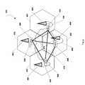
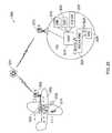
- FIG. 24depicts a particular embodiment of a system to control wireless communications.
- the system 2400includes a mobile base station mimicking system, such as the on-demand cellular (ODC) system 2402 .
- the ODC system 2402may include one or more distributed mobile architecture servers (DMAs) and one or more base station mimicking modules.
- the on-demand cellular system 2402may mimic a commercial wireless network element, such as a base station.
- the ODC system 2402may be configured to support the commercial wireless network where the ODC system 2402 is deployed.
- the ODC system 2402may be configured to communicate with commercial cellular networks commonly used in areas of conflict or war.
- the system 2400also includes a plurality of base stations 2404 - 2418 .
- the plurality of base stations 2404 - 2418may be associated with one or more respective commercial wireless networks.
- each base station 2404 - 2418may provide communications services to communication devices, such as personal computers, laptop computers, mobile phones, pagers, or hand-held computing devices, located within a designated coverage region serviced by a respective base station 2404 - 2418 .
- the base station 2404may provide communication services to a communication device 2420 located within a coverage region 2440
- the base station 2406may provide communication services to a communication device 2422 located within a coverage region 2442
- the base station 2408may provide communication services to a communication device 2424 located within a coverage region 2446 .
- each base station 2404 - 2418may communicate with communication devices located within the designated coverage region of the respective base station via a different channel.
- the base station 2404may communicate with the communication device 2420 within the coverage region 2440 via channel 30 .
- the base station 2406may communicate with the communication device 2422 within the coverage region 2442 via channel 31 and the base station 2408 may communicate with the communication device 2424 within the coverage region 2446 via channel 32 .
- the ODC system 2402may also include a directional antenna and may transmit communication signals to communication devices via the directional antenna.
- the ODC system 2402is operational to transmit communication signals with a peak signal strength approximately along a direction of travel 2434 of the ODC system 2402 .
- the communication signalsmay mimic a base station, such as the base station 2408 , which is a neighboring base station of the targeted base stations 2404 and 2406 along the direction of travel 2434 of the ODC system 2402 .
- the communication signalsmay include ban information related to the targeted base stations 2404 and 2406 .
- the ban informationmay cause a communication device, such as the communication device 2420 , to stop communicating with the base station 2404 .
- the ban informationmay include a noise signal.
- the communication device 2420may be induced to communicate via the ODC system 2402 in response to the communication signals transmitted by the ODC system 2402 mimicking the neighboring base station 2408 .
- the ODC system 2402is configured for data mining or information gathering.
- the ODC system 2402may capture data regarding communication devices in a coverage area.
- the ODC system 2402may capture mobile communication device identification parameters, subscriber identity module (SIM) identification parameters, time stamps, ODC location stamps, location of a communication device relative to the ODC, mobile communication device activity (e.g., call attempts, numbers called, short messaging service (SMS) attempts, numbers messaged, device status), and so forth.
- SIMsubscriber identity module
- time stampse.g., time stamps, ODC location stamps, location of a communication device relative to the ODC
- mobile communication device activitye.g., call attempts, numbers called, short messaging service (SMS) attempts, numbers messaged, device status
- SMSshort messaging service
- the ODC system 2402may also allow monitoring of calls while avoiding the complexity of certain wiretapping systems. For example, communications to and from a target communication device may be passed through the ODC system 2402 and routed to a third party to monitor for intelligence gathering and/or eavesdropping purposes or the ODC system 2402 may monitor communications associated with a particular communication device. Such routing may be transparent to the user of the communication device.
- the communication activitymay be monitored to identify movement or gatherings of communication devices.
- communication activity along routes of interestmay be monitored and analyzed to identify unusual or suspicious activity that may indicate a threat to an armed services unit or civilians.
- the communication activitymay indicate an increase in cellular traffic before or during a mission of an armed services unit, an increase in cellular traffic at an unusual time of day, or the presence of cell phones may appear to be shadowing an armed services unit.
- Communication activitymay also be monitored to identify communication devices with specific area/country codes, such as out-of-area cell phones, and to track communication device presence in suspicious areas.
- the ODC system 2402may be configured to search for a particular communication device.
- the ODC system 2402may search for a communication device having a particular SIM identification (ID).
- the system 2400may include a roaming feature that controls handoff of a mobile communication device between base stations as the mobile communication device moves further from one base station and closer to another.
- a roaming featurethat controls handoff of a mobile communication device between base stations as the mobile communication device moves further from one base station and closer to another.
- mobile communication devices within a movable region of control 2436 near the ODC system 2402such as the mobile communication devices 2420 and 2424 , may be induced to register with the ODC system 2402 for communication services.
- the direction of travel 2434may be predetermined based on a planned course of the ODC system 2402 , or it may be dynamically determined based on, for example, global positioning information, trilateralization using base station signals, other position determining methods, or any combination thereof.
- a roaming feature or a handoff featuremay be set up such that a mobile communication device transitions from a first base station to a second base station based on a signal to noise ratio (SNR) associated with each base station. For example, if the SNR of the first base station is at least 7 dB less than the SNR of the second base station, the mobile communication device may roam or handoff to the second base station.
- the ODC system 2402may take advantage of this roaming feature or handoff feature to induce a communication device to register with the ODC system 2402 for communications.
- the system 2400may include targeted base stations 2404 and 2406 and the ODC system 2402 may acquire data associated with the targeted base stations 2404 and 2406 and data associated with a neighboring base station of the targeted base stations 2404 and 2406 , such as the base station 2408 .
- the neighboring base station 2408is a neighboring base station of the targeted base stations 2404 and 2406 in an expected direction of travel of the ODC system 2402 .
- the acquired base station datamay include a broadcast channel of the respective base station and a list of neighboring base stations related to each respective base station.
- the ODC system 2402may generate a ban signal, such as a noise signal, in the channel used by the targeted base station(s) 2404 and 2406 and a communication signal mimicking the neighboring base station 2408 .
- a ban signalsuch as a noise signal
- communication devices in the coverage region 2444 around the ODC system 2402may perceive an increase in the SNR of the mimicked base station 2408 and a decrease in the SNR of the targeted base station(s) 2404 and 2406 .
- the communication devicesmay be induced to register with the ODC system 2402 according to their roaming feature and handoff properties.
- the ODC system 2402may include multiple ODC units.
- a first ODC unitmay mimic a neighboring base station and a second ODC unit may broadcast duplicate information of the targeted base station.
- a first ODC unit of the ODC system 2402may be transmitting communication signals on channel 32 , which is associated with the base station 2408 , to mimic the base station 2408
- a second ODC unit of the ODC system 2402may transmit communication signals, noise signals, or any combination thereof, on channel 30 and channel 31 to duplicate the targeted base stations 2404 and 2406 .
- the ODC system 2402may control communication signals sent to the captured communication device. For example, communications coming from the captured communication device may be routed to the ODC system 2402 , which may forward the communications to the targeted or mimicked base station. Similarly, the ODC system 2402 may mimic signals of the captured communication device and communicate with a targeted base station as the captured communication device. To illustrate, communications directed to the captured communication device from the targeted or mimicked base station may be received by the ODC system 2402 and selectively forwarded to the captured communication device. In some embodiments, the ODC system 2402 may choose not to forward communications to the captured communication device and may cause a ring back to be sent to the communication device making the call.
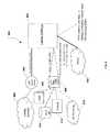
- FIG. 25depicts another particular embodiment of a system to control wireless communications.
- the system 2500includes a base station 2502 , a base station 2504 , and an on-demand cellular (ODC) unit 2506 .
- the base station 2502controls wireless communications within a coverage region 2510
- the base station 2504controls wireless communications within a coverage region 2512
- the ODC unit 2506controls wireless communications in a coverage region 2514 .
- the ODC unit 2506is configured for an improvised explosive device (IED) protection mission.
- the ODC unit 2506may include a passive mode and an active mode. In the passive mode, the ODC unit 2506 may induce mobile communication devices in the coverage area 2514 , such as the mobile communication devices 2520 and 2522 , to roam into coverage of the ODC unit 2506 by taking advantage of the roaming functionality of the mobile communication devices 2520 , 2522 . The mobile communication devices 2520 and 2522 may then be blocked from communicating with the commercial cellular network via the base stations 2502 and 2504 . Thus, if the mobile communication device 2520 or 2522 is coupled to an IED as a triggering device, the ODC unit 2506 may block IED triggering signals from reaching the mobile communication device 2520 or the mobile communication device 2522 .
- IEDimprovised explosive device
- the ODC unit 2506induces mobile communication devices, such as the mobile communication devices 2520 , 2522 , to roam within control of the ODC unit 2506 .
- the ODC unit 2506then calls one or more of the mobile communication devices 2520 , 2522 well in advance of a protected armed forces unit, such as a military vehicle or convoy, coming in proximity to the mobile communication device 2520 , 2522 . If one of the mobile communication devices 2520 , 2522 is set up to trigger an IED, such as the mobile communications device 2522 , the IED is thus detonated well before the protected unit is in danger.
- the coverage area 2514 provided by the ODC unit 2506may be from about 2 to 10 kilometers.
- the ODC unit 2506may call a mobile communication device that is set up to trigger an IED at a selected time based on a location of a protected unit, based on a direction of travel of the protected unit, based on the rate of travel of the protected unit, or any combination thereof.
- FIG. 26depicts another embodiment of a system to control wireless communications.
- the system 2600includes a first on-demand cellular (ODC) system 2602 and a second ODC system 2604 .
- the first ODC system 2602controls communications in a coverage area 2650
- the second ODC system 2604controls communications in a coverage area 2652 .
- the system 2600also includes base stations 2606 - 2614 .
- the base station 2606controls communications in a coverage area 2616 and communicates via channel 30
- the base station 2608controls communications in a coverage area 2618 and communicates via channel 31 .
- the base station 2610controls communications in a coverage area 2620 and communicates via channel 32
- the base station 2612controls communications in a coverage area 2622 and communicates via channel 33 .
- the base station 2614controls communications in a coverage area 2624 and communicates via channel 34 .
- the first ODC system 2602includes an ODC Unit A 2628 , an ODC Unit B 2630 , and an ODC Unit C 2632 .
- the second ODC system 2604includes an ODC Unit D 2634 , an ODC Unit E 2636 , and an ODC Unit F 2638 .
- the ODC systems 2602 , 2604may be moving in a direction of travel 2626 .
- the first ODC system 2602may serve as a working system that acquires information from targeted base stations and mimics communication signals of targeted base stations.
- the first ODC system 2602may also identify one or more neighboring base stations based on the location of the first ODC system 2602 , the direction of travel 2626 of the first ODC system 2602 and the second ODC system 2604 , or any combination thereof.
- the first ODC system 2602may determine that the targeted base station 2606 communicates via the channel 30 and the targeted base station 2612 communicates via the channel 33 .
- the first ODC system 2602may also determine that the base stations 2608 and 2614 are neighboring base stations of the targeted base stations 2606 and 2612 and that the base station 2608 communicates via the channel 31 and that the base station 2614 communicates via the channel 34 . Further, the first ODC system 2602 may determine that the base station 2610 is a neighboring base station of the base stations 2608 and 2614 and that the base station 2610 communicates via the channel 32 .
- the working systemmay utilize the ODC Unit A 2628 to duplicate the broadcast channel of the targeted base station 2606 using the channel 30 and utilize the ODC Unit B 2630 to duplicate the broadcast channel of the targeted base station 2612 using the channel 33 .
- the ODC Unit A 2628may also send a noise signal using the channel 30 to decrease the signal to noise ratio with respect to the base station 2606 and communication devices in the coverage area 2650 .
- the ODC Unit B 2630may send a noise signal using the channel 33 to decrease the signal to noise ratio with respect to the base station 2612 and communication devices in the coverage area 2650 .
- the first ODC system 2602may utilize the ODC Unit C 2632 to mimic the communication signals of the neighboring base station 2608 using channel 31 .
- communication devices in the coverage area 2650may be induced to roam onto the first ODC system 2602 , which is mimicking the neighboring base station 2608 .
- the second ODC system 2604may serve as a prepare system that prepares for mimicking subsequent base stations.
- the prepare systemsuch as the second ODC system 2604 , may acquire the channel broadcast information and neighboring base station information from the base stations 2608 , 2610 , and 2614 and may prepare to transition to the first neighboring unit, that is the base station 2608 , as a first targeted unit and prepare to transition to the second neighboring unit, that is the base station 2614 , as a second targeted unit.
- the ODC Unit D 2634 of the second ODC system 2604may duplicate the broadcast channel of the base station 2608 using the channel 31 and the ODC Unit E 2636 of the second ODC system 2604 may duplicate the broadcast channel of the base station 2614 using the channel 34 .
- the ODC Unit F 2638 of the second ODC system 2604may mimic the communication signals of the base station 2610 , which is a neighboring base station of the base stations 2608 and 2614 , using channel 32 .
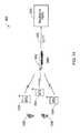
- FIG. 27depicts another embodiment of a system to control wireless communications.
- the system 2700includes a first on-demand cellular (ODC) system 2702 , a second ODC system 2704 , and a third ODC system 2706 .
- the first ODC system 2702controls communications in a coverage area 2708
- the second ODC system 2704controls communications in a coverage area 2710
- the third ODC system 2706controls communications in a coverage area 2712 .
- the system 2700also includes base stations 2714 - 2718 .
- the base station 2714controls communications in a coverage area 2720 and communicates via channel 30
- the base station 2716controls communications in a coverage area 2722 and communicates via channel 31 .
- the base station 2718controls communications in a coverage area 2724 and communicates via channel 32 .
- the first ODC system 2702includes an ODC Unit A 2726 and an ODC Unit B 2728 and the second ODC system 2704 includes an ODC Unit C 2730 and an ODC Unit D 2732 .
- the third ODC system 2706includes an ODC Unit E 2734 and an ODC Unit F 2736 .
- the ODC systems 2702 and 2704may be moving in a direction of travel 2720 .
- the first ODC system 2702may serve as a working system that acquires information from targeted base stations and mimics communication signals of the targeted base stations.
- the first ODC system 2702may also identify one or more neighboring base stations based on the location of the first ODC system 2702 , the direction of travel 2720 of the first ODC system 2702 and the second ODC system 2704 , or any combination thereof. Additionally, the first ODC system 2702 may determine that the targeted base station 2714 communicates via the channel 30 and that the base station 2716 is a neighboring base station of the base station 2714 . Further, the first ODC system 2702 may determine that the base station 2718 is a neighboring base station of the base station 2716 and that the base station 2718 communicates via the channel 32 .
- the second ODC system 2704may serve as a prepare system that prepares for mimicking subsequent base stations.
- the second ODC system 2704may acquire the channel broadcast information and neighboring base station information from the base stations 2716 and 2718 .
- the third ODC system 2706may predict subsequent base stations related to the base stations 2714 - 2718 .
- the third ODC system 2712may identify neighboring base stations with respect to the base stations 2716 and 2718 .
- the third ODC system 2706may be included in a vehicle, such as a helicopter, tank, or airplane.
- the working systemmay utilize the ODC unit A 2726 to duplicate the broadcast channel of the targeted base station 2714 using the channel 30 and may utilize the ODC unit B 2728 to mimic the communication signals of the neighboring base station 2716 using the channel 31 .
- the ODC unit A 2726may also send a noise signal using the channel 30 to decrease the signal to noise ratio with respect to the base station 2714 and communication devices in the coverage area 2708 .
- communication devices in the coverage area 2708may be induced to roam onto the first ODC system 2702 , which is mimicking the neighboring base station 2716 .
- the prepare system, the second ODC system 2704may prepare to transition to the first neighboring unit, the base station 2716 , as a first targeted unit.
- the ODC unit C 2730 of the second ODC system 2704may duplicate the broadcast channel of the base station 2716 using the channel 31 .
- the ODC unit D 2732 of the second ODC system 2704may mimic the communication signals of the base station 2718 , which is a neighboring base station of the base station 2716 .
- the ODC Unit E 2734 and the ODC Unit F 2736 of the third ODC system 2706may be used to duplicate and/or mimic signals of neighboring base stations of the base station 2718 .
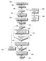
- FIG. 28is a flow diagram of an embodiment of a method to control wireless communications.
- a mobile base station mimicking systemsuch as an on-demand cellular (ODC) system, acquires first base station data from a first base station.
- ODCon-demand cellular
- the mobile base station mimicking systemmay acquire a channel utilized by the first base station to communicate and a list of neighboring base stations associated with the first base station.
- the mobile base station mimicking systemacquires second base station data from a second base station.
- the mobile base station mimicking systemmay acquire a channel utilized by the second base station to communicate and a list of neighboring base stations associated with the second base station.
- the second base stationmay be a targeted base station and the first base station may be a neighboring base station of the second base station. Further, the data acquired from the first base station and the second base station may be associated with one or more commercial networks that include the first base station and the second base station.
- the mobile base station mimicking systemmimics signals of the first base station based on the acquired first base station data.
- the mobile base station mimicking systemmay mimic identification signals related to the first base station that are transmitted by the first base station to communication devices within a coverage area served by the first base station.
- the mobile base station mimicking systeminduces a mobile communication device to switch from being registered with the second base station to register with the mobile base station mimicking system.
- the mobile base station mimicking systemmay transmit a noise signal on a channel used by the second base station to decrease a signal to noise ratio with respect to the second base station and the mobile communication device. When the signal to noise ratio reaches a specified threshold, the mobile communication device may attempt to register with another base station.
- the mobile base station mimicking systemis transmitting duplicate signals of neighboring base stations of the second base station, such as the first base station
- the mobile base station mimicking systemcan capture a registration request from the mobile communication device and register the mobile communication device with the mobile base station mimicking system.
- the handoff to the mobile base station mimicking systemis transparent to the mobile communication device user.
- the call bars, the logo of the wireless carrier associated with the mobile communication device, identification information of the wireless carrier, or any combination thereofmay still be presented via the mobile communication device.
- the mobile communication devicemay be in an active call mode, such as during a phone call, when the mobile communication device registers with the mobile base station mimicking system or the mobile communication device may be turned on, but not in use.
- the mobile base station mimicking systemcontrols communications associated with the mobile communication device.
- the mobile base station mimicking systemmay switch calls to and from the mobile communication device and operate in a similar manner to a commercial wireless network base station.
- the mobile base station mimicking systemmay also block signals from being sent to the mobile communication device.
- the mobile communication devicemay serve as a triggering device for an improvised explosive device (IED), and the mobile base station mimicking system may block a triggering signal from being sent to the mobile communication device.
- the mobile base station mimicking systemmay also send a triggering signal to the mobile communication device to set off the IED associated with the mobile communication device when an armed forces unit or civilians are not in danger of being affected by the detonation.
- IEDimprovised explosive device
- the mobile base station mimicking systemmay mimic the mobile communication device and receive communication data that is directed to the mobile communication device from base stations of a commercial wireless network.
- the communication data received from the wireless network base stationsmay or may not be forwarded to the mobile communication device.
- the mobile base station mimicking systemmay also send a communication notification to the mobile communication device. The method terminates at 2812 .
- the present disclosureprovides a system and method of controlling communications through use of a flexible telecommunications device, i.e., the DMA server 406 ( FIG. 4 ), that is distributive and associative, i.e., it can operate stand-alone or seamlessly within an existing cellular or other network.
- the DMA server 406can be integrated with virtually any third party base station.
- the DMA server 406can operate with multiple air interfaces including CDMA IS-95, CDMA 1X, CDMA EVDO, GSM, GPRS, W-CDMA, 802.11 (Wi-fi), 802.16 (Wi-fi), etc.
- the DMA server 406can provide integrated prepaid billing, OAMP, network management, and AAA functionality.
- the DMA server 406can include a Java based user interface and feature configuration system.
- the DMA server 406can provide real time call metering, call detail record (CDR) generation, and real time call provisioning.
- the DMA server 406may be implemented in a relatively small footprint and has a relatively low power requirement. Further, the DMA server 406 may be implemented using inexpensive and widely available computer equipment.
- the present systemprovides mobile to landline calls from mobile handsets within a DMA server cellular coverage area.
- mobile to landline callscan be made from mobile handsets roaming into DMA coverage areas.
- Mobile to mobile callscan be made from home/roaming handsets to DMA handsets and vice versa.
- mobile to IP calls and IP to mobile callscan be made from within a DMA server coverage area.
- IP to IP callscan be made from any DMA handset to any IP phone.
- IP to landline calls and landline to IP callscan be made from a DMA handset to any phone.
- land-line to mobile calls to DMA handsetscan be made.
- the systems described abovecan support call forwarding, call waiting, 3-way calling caller ID, voice mail, and mobile to mobile SMS service, i.e., text messaging. Further, the systems described above can provide broadcast SMS service, mobile to land high-speed IP data (1 ⁇ or GPRS) service and mobile-to-mobile high speed IP data (1 ⁇ or GPRS) service. Also, the systems described above can provide IP-PBX capability.
- one or more of the illustrated systemscan provide IP transport between distributed elements, e.g., DMA servers 406 ( FIG. 4 ). Packet back-haul from BTS to RAN can be provided. Further, the control logic within the DMA servers 406 ( FIG. 4 ) can be distributed and associated. Associated systems can be redundant, self-healing, self-organizing, and scalable. Distributed systems can be “snap-together,” i.e., a DMA server 406 ( FIG. 4 ) can be linked to a previously deployed DMA server 406 ( FIG. 4 ) in order to broaden, or otherwise extend, cellular coverage. Further, distributed systems can be de-centralized to avoid single points of failure.
- One or more of the systems described abovecan also provide soft and softer call handoffs on the same frequency interfaces. Also, soft handoffs can be provided on different systems. Further, a DMA based system can operate stand-alone with a billing system provided by a DMA server and CDR generation. Or, a system can use the SS7 network to pass CDRs to a central switch for integrated billing and operation with an existing network.
Landscapes
- Engineering & Computer Science (AREA)
- Computer Networks & Wireless Communication (AREA)
- Signal Processing (AREA)
- Computer Security & Cryptography (AREA)
- Aviation & Aerospace Engineering (AREA)
- General Physics & Mathematics (AREA)
- Physics & Mathematics (AREA)
- Astronomy & Astrophysics (AREA)
- Technology Law (AREA)
- Computer Hardware Design (AREA)
- Computing Systems (AREA)
- General Engineering & Computer Science (AREA)
- Mobile Radio Communication Systems (AREA)
Abstract
Description
Claims (25)
Priority Applications (3)
| Application Number | Priority Date | Filing Date | Title |
|---|---|---|---|
| US11/955,017US8676197B2 (en) | 2006-12-13 | 2007-12-12 | System, method, and device to control wireless communications |
| PCT/US2007/025538WO2008150281A1 (en) | 2006-12-13 | 2007-12-13 | System, method, and device to control wireless communications |
| US14/177,119US9515770B2 (en) | 2006-12-13 | 2014-02-10 | System, method, and device to control wireless communications |
Applications Claiming Priority (2)
| Application Number | Priority Date | Filing Date | Title |
|---|---|---|---|
| US86989006P | 2006-12-13 | 2006-12-13 | |
| US11/955,017US8676197B2 (en) | 2006-12-13 | 2007-12-12 | System, method, and device to control wireless communications |
Related Child Applications (1)
| Application Number | Title | Priority Date | Filing Date |
|---|---|---|---|
| US14/177,119ContinuationUS9515770B2 (en) | 2006-12-13 | 2014-02-10 | System, method, and device to control wireless communications |
Publications (2)
| Publication Number | Publication Date |
|---|---|
| US20080146158A1 US20080146158A1 (en) | 2008-06-19 |
| US8676197B2true US8676197B2 (en) | 2014-03-18 |
Family
ID=39527923
Family Applications (2)
| Application Number | Title | Priority Date | Filing Date |
|---|---|---|---|
| US11/955,017Active - Reinstated2031-01-11US8676197B2 (en) | 2006-12-13 | 2007-12-12 | System, method, and device to control wireless communications |
| US14/177,119Active2028-03-27US9515770B2 (en) | 2006-12-13 | 2014-02-10 | System, method, and device to control wireless communications |
Family Applications After (1)
| Application Number | Title | Priority Date | Filing Date |
|---|---|---|---|
| US14/177,119Active2028-03-27US9515770B2 (en) | 2006-12-13 | 2014-02-10 | System, method, and device to control wireless communications |
Country Status (2)
| Country | Link |
|---|---|
| US (2) | US8676197B2 (en) |
| WO (1) | WO2008150281A1 (en) |
Cited By (9)
| Publication number | Priority date | Publication date | Assignee | Title |
|---|---|---|---|---|
| US20140057636A1 (en)* | 2012-08-24 | 2014-02-27 | Oceus Networks Inc. | Mobile cellular networks |
| US9226192B2 (en) | 2013-04-29 | 2015-12-29 | Oceus Networks Inc. | Mobile cellular network backhaul |
| US9445280B2 (en) | 2012-08-24 | 2016-09-13 | Oceus Networks Inc. | Mobile cellular networks |
| US9686238B1 (en) | 2016-07-07 | 2017-06-20 | Oceus Networks Inc. | Secure network enrollment |
| US9924427B2 (en) | 2016-07-07 | 2018-03-20 | Oceus Networks Inc. | Network backhaul access |
| US10172078B2 (en) | 2017-03-31 | 2019-01-01 | Oceus Networks Inc. | Targeted user equipment-base station communication link |
| US10873891B2 (en) | 2016-07-06 | 2020-12-22 | Oceus Networks, Llc | Secure network rollover |
| US11246031B2 (en) | 2018-08-15 | 2022-02-08 | Oceus Networks, Llc | Disguising UE communications in a cellular network |
| US11997762B2 (en) | 2019-12-19 | 2024-05-28 | Comcast Cable Communications, Llc | Methods and systems for switching between service provider networks |
Families Citing this family (32)
| Publication number | Priority date | Publication date | Assignee | Title |
|---|---|---|---|---|
| US7486967B2 (en)* | 2005-04-13 | 2009-02-03 | Lemko Corporation | System, method, and device for providing communications using a distributed mobile architecture |
| US7548763B2 (en)* | 2005-04-13 | 2009-06-16 | Lemko Corporation | System, method, and device for providing communications using a distributed mobile architecture |
| US7539158B2 (en) | 2004-11-08 | 2009-05-26 | Lemko Corporation | System, method and device for providing communications using a distributed mobile architecture |
| US7856233B2 (en) | 2006-03-30 | 2010-12-21 | Lemko Corporation | System, method, and device for providing communications using a distributed mobile architecture |
| US8224322B2 (en) | 2006-06-12 | 2012-07-17 | Lemko Corporation | Roaming mobile subscriber registration in a distributed mobile architecture |
| US8676197B2 (en) | 2006-12-13 | 2014-03-18 | Lemko Corporation | System, method, and device to control wireless communications |
| US8046420B2 (en) | 2008-04-23 | 2011-10-25 | Lemko Corporation | System and method to control wireless communications |
| US8340667B2 (en) | 2008-06-26 | 2012-12-25 | Lemko Corporation | System and method to control wireless communications |
| US8706105B2 (en) | 2008-06-27 | 2014-04-22 | Lemko Corporation | Fault tolerant distributed mobile architecture |
| US8107409B2 (en) | 2008-07-11 | 2012-01-31 | Lemko Corporation | OAMP for distributed mobile architecture |
| US7855988B2 (en) | 2008-07-14 | 2010-12-21 | Lemko Corporation | System, method, and device for routing calls using a distributed mobile architecture |
| US7979066B2 (en) | 2008-09-25 | 2011-07-12 | Lemko Corporation | Multiple IMSI connections |
| US9210220B2 (en)* | 2008-09-29 | 2015-12-08 | Andrew Steckley | System and method for intelligent automated remote management of electromechanical devices |
| US8825011B2 (en) | 2008-12-19 | 2014-09-02 | Tecore, Inc. | Intelligent network access control |
| US8437741B2 (en) | 2008-12-19 | 2013-05-07 | Tecore | Intelligent network access controller and method |
| US8254886B2 (en)* | 2008-12-19 | 2012-08-28 | Tecore, Inc. | Intelligent network access controller and method |
| EP2320699A1 (en)* | 2009-11-10 | 2011-05-11 | Alcatel Lucent | A Femtocell base station, and a method of triggering transfer of a radio connection with a user terminal from a macrocell base station to a femtocell base station |
| US8606322B2 (en)* | 2010-10-25 | 2013-12-10 | Raytheon Applied Signal Technology, Inc. | Portable cellular base station configuration |
| US8588853B2 (en) | 2010-10-25 | 2013-11-19 | Raytheon Applied Signal Technology, Inc. | Femtocell configuration |
| DE102010062339A1 (en)* | 2010-12-02 | 2012-06-06 | Siemens Programm- Und Systementwicklung Gmbh & Co. Kg | Method for detecting active mobile stations |
| US8681953B2 (en) | 2011-05-30 | 2014-03-25 | Curtis E. Quady | Interactive property communication system |
| US8683064B2 (en) | 2011-05-30 | 2014-03-25 | Curtis E. Quady | Interactive property communication system |
| US8548439B2 (en) | 2011-05-30 | 2013-10-01 | Curtis E. Quady | Interactive property communication system |
| US8675835B2 (en) | 2011-05-30 | 2014-03-18 | Curtis E. Quady | Interactive property communication system |
| US8687778B2 (en) | 2011-05-30 | 2014-04-01 | Curtis E. Quady | Interactive property communication system |
| WO2013119156A1 (en)* | 2012-02-09 | 2013-08-15 | Telefonaktiebolaget L M Ericsson (Publ) | Full and partial resource access in ran sharing |
| US9456182B2 (en)* | 2012-02-21 | 2016-09-27 | Pure Software Solutions, Inc. | Pipeline cleaning systems and methods |
| DE102012205884A1 (en)* | 2012-04-11 | 2013-10-17 | Lufthansa Systems Ag | Data communication device for a means of transport |
| US9313701B2 (en)* | 2013-06-04 | 2016-04-12 | Utx Technologies Limited | Seamless handoff and call binding |
| US9532398B2 (en) | 2013-09-11 | 2016-12-27 | Star Solutions International Inc. | Portable cellular network system |
| CN107631667B (en)* | 2017-10-30 | 2019-04-12 | 北京电子工程总体研究所 | A kind of fuze sled test timing automatic control device |
| CN112316992A (en)* | 2020-10-13 | 2021-02-05 | 南京英飞达自动化设备有限公司 | High-low temperature rapid alternating damp-heat test box and test method thereof |
Citations (154)
| Publication number | Priority date | Publication date | Assignee | Title |
|---|---|---|---|---|
| US4284848A (en) | 1979-08-01 | 1981-08-18 | Frost Edward G | Switched network telephone subscriber distribution system |
| EP0365885B1 (en) | 1988-10-28 | 1995-09-13 | Motorola, Inc. | Satellite cellular telephone and data communication system |
| US5590175A (en) | 1995-05-17 | 1996-12-31 | Mci Communications Corporation | Method and system for enhanced call completion in telecommunications mobility applications |
| US5623495A (en) | 1995-06-15 | 1997-04-22 | Lucent Technologies Inc. | Portable base station architecture for an AD-HOC ATM lan |
| US5734979A (en) | 1995-05-04 | 1998-03-31 | Interwave Communications International, Ltd. | Cellular base station with intelligent call routing |
| US5933784A (en) | 1996-06-28 | 1999-08-03 | Synacom Technology, Inc. | Signaling gateway system and method |
| US5991639A (en) | 1996-10-02 | 1999-11-23 | Nokia Mobile Phones Limited | System for transferring a call and a mobile station |
| US6122499A (en) | 1998-07-31 | 2000-09-19 | Iridium, L.L.C. | System and/or method for call intercept capability in a global mobile satellite communications system |
| US6131038A (en) | 1997-05-14 | 2000-10-10 | Oki Electric Co., Ltd. | Method of and apparatus for selecting a channel in a base station by determining the field intensity of radiowaves received |
| US6141564A (en) | 1999-09-30 | 2000-10-31 | Motorola, Inc. | Method of sharing a SIM card between two masters |
| US6160804A (en) | 1998-11-13 | 2000-12-12 | Lucent Technologies Inc. | Mobility management for a multimedia mobile network |
| US20010036173A1 (en) | 2000-02-08 | 2001-11-01 | Shmulevich Oren T | Convergence of telephone signaling, voice and data over a packet-switched network |
| US20010046859A1 (en) | 2000-05-24 | 2001-11-29 | Tae-Young Kil | System and method for providing public/private mobile communication service |
| US20010055298A1 (en) | 2000-05-10 | 2001-12-27 | John Baker | Apparatus and system to provide wireless data services through a wireless access integrated node |
| US20020009060A1 (en) | 2000-05-05 | 2002-01-24 | Todd Gross | Satellite transceiver card for bandwidth on demand applications |
| US20020016180A1 (en)* | 2000-07-25 | 2002-02-07 | Derosier J. David | Communication device intervention system and method |
| US20020015392A1 (en) | 2000-01-25 | 2002-02-07 | Niilo Musikka | Method and system for optimal routing of calls in a base station system |
| US20020045444A1 (en) | 2000-04-14 | 2002-04-18 | Usher Martin Philip | Mobile telephony |
| US20020051518A1 (en) | 2000-04-07 | 2002-05-02 | Bondy William Michael | Communication network with a collection gateway and method for providing surveillance services |
| US20020058502A1 (en) | 2000-11-13 | 2002-05-16 | Peter Stanforth | Ad hoc peer-to-peer mobile radio access system interfaced to the PSTN and cellular networks |
| US20020061746A1 (en) | 2000-11-23 | 2002-05-23 | Jo Jin Mahn | Method of global roaming services using gateway location register in third generation mobile telecommunication networks |
| US6411825B1 (en) | 1997-09-09 | 2002-06-25 | Samsung Electronics, Co., Ltd. | Distributed architecture for a base station transceiver subsystem |
| US6418308B1 (en) | 1996-08-29 | 2002-07-09 | Nokia Mobile Phones Ltd. | Opinion poll utilizing a wireless data transmission connection |
| US6421325B1 (en) | 1998-04-28 | 2002-07-16 | Genesys Telecomm Lab Inc | Methods and apparatus for enhancing wireless data network telephony including a personal router in a client |
| US20020160772A1 (en) | 2001-04-27 | 2002-10-31 | Gailey Michael L. | Routing call failures in a location-based services system |
| US20020169887A1 (en) | 2000-12-11 | 2002-11-14 | Melampy Patrick J. | System and method for assisting in controlling real-time transport protocol flow through multiple networks via screening |
| US20030048766A1 (en) | 2001-08-31 | 2003-03-13 | D'annunzio Michael A. | Point-to-point protocol over ethernet for mobile platforms |
| US6539237B1 (en) | 1998-11-09 | 2003-03-25 | Cisco Technology, Inc. | Method and apparatus for integrated wireless communications in private and public network environments |
| US6542497B1 (en) | 1997-03-11 | 2003-04-01 | Verizon Services Corp. | Public wireless/cordless internet gateway |
| US20030063721A1 (en) | 2001-09-28 | 2003-04-03 | Fujitsu Limited | Telephone service method and telephone service apparatus |
| US20030088698A1 (en) | 2001-11-06 | 2003-05-08 | Inderpreet Singh | VPN failure recovery |
| US20030092441A1 (en) | 2001-11-15 | 2003-05-15 | Mehmet Taha | Method and apparatus for providing services in a private wireless network |
| US20030096628A1 (en) | 2001-07-27 | 2003-05-22 | David Bar-On | System, method and transceiver for mobile communications |
| US20030100302A1 (en) | 2001-11-29 | 2003-05-29 | Armbruster Peter J. | User controlled home location register |
| US20030100342A1 (en) | 2001-11-28 | 2003-05-29 | Young-Cheol Ham | Public land mobile network / private wireless network-integrated service network and system for the same |
| US20030112748A1 (en) | 2001-12-17 | 2003-06-19 | Puppa Gary J. | System and method for detecting failures and re-routing connections in a communication network |
| US6584098B1 (en) | 1997-09-04 | 2003-06-24 | British Telecommunications Public Limited Company | Telecommunications system |
| US20030153343A1 (en) | 2002-02-14 | 2003-08-14 | Crockett Douglas M. | Communication device for initiating a group call in a group communication network |
| US6611533B1 (en) | 1999-01-13 | 2003-08-26 | Nortel Networks Limited | Public telephone network, intelligent network, and internet protocol network services interworking |
| US6614784B1 (en) | 1999-01-15 | 2003-09-02 | Telefonaktiebolaget L M Ericsson (Publ) | System and method for providing supplementary services (SS) in an integrated telecommunications network |
| US20030198325A1 (en) | 2002-04-20 | 2003-10-23 | Bayne Anthony J. | Pre-paid calling and voice messaging services for inmates |
| US6647426B2 (en) | 2001-02-26 | 2003-11-11 | Kineto Wireless, Inc. | Apparatus and method for integrating an unlicensed wireless communications system and a licensed wireless communications system |
| US6678155B1 (en) | 1999-12-14 | 2004-01-13 | Hewlett-Packard Company | Modular system of internet service provider focused computer services |
| US20040014466A1 (en) | 2002-02-25 | 2004-01-22 | Radioframe Networks | Radio system having distributed real-time processing |
| US20040018829A1 (en) | 2002-07-25 | 2004-01-29 | 3Com Corporation | Roaming and hand-off support for prepaid billing for wireless data networks |
| US20040019539A1 (en) | 2002-07-25 | 2004-01-29 | 3Com Corporation | Prepaid billing system for wireless data networks |
| US6694134B1 (en) | 2002-03-18 | 2004-02-17 | Interwave Communications International, Ltd. | Terminal device emulator |
| US6697355B1 (en) | 1997-12-31 | 2004-02-24 | Lg Information & Communications, Ltd. | Method and apparatus for communication using a mobile internet in a mobile communication network |
| US6704409B1 (en) | 1997-12-31 | 2004-03-09 | Aspect Communications Corporation | Method and apparatus for processing real-time transactions and non-real-time transactions |
| US6731932B1 (en) | 1999-08-24 | 2004-05-04 | Telefonaktiebolaget Lm Ericsson (Publ) | Methods and systems for handling subscriber data |
| US6735184B1 (en) | 2000-03-21 | 2004-05-11 | Ericsson Inc | Internet protocol network architecture for a global satellite system |
| US6751207B1 (en) | 1999-07-27 | 2004-06-15 | Cellco Partnership | Tunnelling voice over the internet protocol in a cellular network |
| US6760325B1 (en) | 1999-03-24 | 2004-07-06 | Telefonaktiebolaget Lm Ericsson (Publ) | Processing of mobile originated calls in packet switched protocol based communication networks |
| US6763226B1 (en) | 2002-07-31 | 2004-07-13 | Computer Science Central, Inc. | Multifunctional world wide walkie talkie, a tri-frequency cellular-satellite wireless instant messenger computer and network for establishing global wireless volp quality of service (qos) communications, unified messaging, and video conferencing via the internet |
| US6763233B2 (en) | 2000-01-05 | 2004-07-13 | Nortel Networks Limited | Terminal roaming operations between intergenerational wireless networks |
| US20040156495A1 (en) | 2003-02-07 | 2004-08-12 | Venkatesh Chava | Intermediary network system and method for facilitating message exchange between wireless networks |
| US6791988B1 (en) | 1999-04-29 | 2004-09-14 | Telefonaktiebolaget Lm Ericsson | Processing of calls terminating in a packet switched protocol based cellular communication network |
| US6795444B1 (en) | 1999-10-26 | 2004-09-21 | Telefonaktiebolaget L M Ericsson (Publ) | System and method for providing wireless telephony over a packet-switched network |
| US20040203677A1 (en) | 2002-10-23 | 2004-10-14 | International Business Machines Corporation | System and method for conference call line drop recovery |
| US20040204097A1 (en) | 2002-10-25 | 2004-10-14 | Ibis Telecom, Inc. | Internet base station |
| US20040203621A1 (en) | 2002-10-23 | 2004-10-14 | International Business Machines Corporation | System and method for queuing and bookmarking tekephony conversations |
| US6807432B2 (en) | 2001-08-08 | 2004-10-19 | Hong-Wen Hwang | Wireless transmission network card |
| CN1538781A (en) | 2003-04-17 | 2004-10-20 | ��������˹�����տ����� | Interoperable voice data wireless network |
| US6816706B1 (en) | 1999-09-08 | 2004-11-09 | Qwest Communications International, Inc. | Wireless communication access point |
| US6819652B1 (en) | 2000-06-21 | 2004-11-16 | Nortel Networks Limited | Method and apparatus for processing control messages in a communications system |
| US6831903B2 (en) | 2000-05-24 | 2004-12-14 | Samsung Electronics Co., Ltd. | Method of providing public network service when call management device is in a down state in private wireless network |
| US20040253984A1 (en) | 2002-04-26 | 2004-12-16 | Samsung Electronics Co., Ltd. | Apparatus and method for adapting WI-FI access point to wireless backhaul link of a wireless network |
| US20040253949A1 (en) | 2003-04-02 | 2004-12-16 | The Boeing Company | Platform-associated visitor location registers (VLR) for cellular communications |
| US20040259556A1 (en) | 2003-02-13 | 2004-12-23 | Baruch Czys | Wireless network with intensive frequency reuse |
| US6839356B2 (en) | 2000-02-22 | 2005-01-04 | Nortel Networks Limited | System and method for controlling a wireless packet switched voice call |
| US6859652B2 (en) | 2000-08-02 | 2005-02-22 | Mobile Satellite Ventures, Lp | Integrated or autonomous system and method of satellite-terrestrial frequency reuse using signal attenuation and/or blockage, dynamic assignment of frequencies and/or hysteresis |
| US6871072B1 (en) | 1997-09-23 | 2005-03-22 | Nokia Corporation | Methods and apparatus for supporting optimum call routing in a cellular telecommunications system |
| US20050064922A1 (en)* | 2003-09-19 | 2005-03-24 | Owens William R. | Detector and method for detecting telephone-activated devices in idle state |
| US20050070278A1 (en) | 2003-08-13 | 2005-03-31 | Jiang Yue Jun | Signaling gateway with multiple IMSI with multiple MSISDN (MIMM) service in a single SIM for multiple roaming partners |
| US20050075106A1 (en) | 2003-08-13 | 2005-04-07 | Jiang Yue Jun | Multiple IMSI multiple/single MSISDN (MIMM/MISM) on multiple SIMs for a single operator |
| US6879677B2 (en) | 2001-11-01 | 2005-04-12 | Callwave, Inc. | Methods and systems for telephony call completion |
| US6879582B1 (en) | 2000-09-29 | 2005-04-12 | Lucent Technologies Inc. | Media terminal adapter-cellular transceiver (MTA-CT) |
| US20050091392A1 (en) | 2001-12-21 | 2005-04-28 | Lothar Gesswein | Method and device for codec negotiation |
| US6917813B2 (en) | 2001-05-31 | 2005-07-12 | Telefonaktiebolaget Lm Ericsson (Publ) | Provision of short message services |
| US20050176413A1 (en) | 2004-02-06 | 2005-08-11 | Sung-Hoon Lee | Method and system for providing data service in interworking wireless public and private networks |
| US20050250491A1 (en) | 2000-05-02 | 2005-11-10 | Roy Radhika R | System and method for inter-domain mobility management |
| US6985454B1 (en) | 1999-01-26 | 2006-01-10 | Globalstar L.P. | ISP system using non-geosynchronous orbit satellites |
| US20060046714A1 (en) | 2004-08-30 | 2006-03-02 | Asawaree Kalavade | Mobile services control platform providing a converged voice service |
| US20060046760A1 (en) | 2004-08-24 | 2006-03-02 | Bertino Jeffrey S | Optimistic talk-permit reliability enhancement in a push-to-talk system |
| US20060047836A1 (en) | 2004-08-13 | 2006-03-02 | Rao Goutham P | A method for maintaining transaction integrity across multiple remote access servers |
| US20060052113A1 (en) | 2004-09-07 | 2006-03-09 | Shai Ophir | Roaming presence and context management |
| US20060063544A1 (en) | 2002-11-04 | 2006-03-23 | Research In Motion Limited | Method and system for maintaining a wireless data connection |
| US20060098661A1 (en) | 2004-11-08 | 2006-05-11 | Lemko Corporation | System, method and device for providing communications using a distributed mobile architecture |
| WO2006052342A2 (en) | 2004-11-08 | 2006-05-18 | Lemko, Corporation | System, method, and device for providing communications using a distributed mobile architecture |
| US7050414B2 (en) | 2001-06-22 | 2006-05-23 | Lucent Technologies Inc. | Method and apparatus for setting up a call over a packet-based transport network |
| US7054307B2 (en) | 2000-12-29 | 2006-05-30 | Telefonaktiebolaget Lm Ericsson (Publ) | Method, apparatus and system for managing subscriber data |
| US20060114934A1 (en) | 2004-11-26 | 2006-06-01 | Minsu Shin | Network operation method in interactive satellite communications system |
| US20060142011A1 (en) | 2004-12-23 | 2006-06-29 | Nokia Corporation | Method for the routing of communications to a voice over internet protocol terminal in a mobile communication system |
| US20060141984A1 (en) | 2004-12-29 | 2006-06-29 | Claudio Taglienti | Client-based context-based billing for wireless networks |
| US20060148465A1 (en)* | 2004-12-30 | 2006-07-06 | Perdomo Jorge L | System and method for providing an adaptive disablement zone |
| US20060159039A1 (en) | 2004-12-21 | 2006-07-20 | Tae-Sung Jung | Method and system for providing private voice call service to mobile subscriber and wireless soft switch apparatus therefor |
| US20060203746A1 (en) | 2005-03-10 | 2006-09-14 | Mark Maggenti | Method and apparatus for automatic configuration of wireless communication networks |
| US20060217121A1 (en)* | 2005-03-25 | 2006-09-28 | Soliman Samir S | System and method for creating a wireless picocell |
| US20060221912A1 (en) | 2005-04-01 | 2006-10-05 | Cml Emergency Services Inc. | Radio gateway system and method for interfacing a radio system and an IP network |
| US7120435B2 (en) | 2000-04-14 | 2006-10-10 | Stratos Global Ltd. | Mobile cellular radio |
| US7120436B2 (en)* | 2001-12-04 | 2006-10-10 | Samsung Electronics Co., Ltd. | Method and system for updating of home-zone list automatically in mobile telecommunication system |
| US20060234774A1 (en) | 2005-04-13 | 2006-10-19 | Lemko, Corporation | System, method, and device for providing communications using a distributed mobile architecture |
| US20060234747A1 (en) | 2005-04-13 | 2006-10-19 | Lemko, Corporation | System, method, and device for providing communications using a distributed mobile architecture |
| US7133670B1 (en) | 2003-12-29 | 2006-11-07 | Sprint Spectrum L.P. | Roaming agreement application and database for carrying out roaming between private and public wireless networks |
| US20060258358A1 (en) | 2005-05-11 | 2006-11-16 | Nokia Corporation | Method for performing inter-system handovers in a mobile communication system |
| US20070008968A1 (en) | 2005-06-29 | 2007-01-11 | Honeywell International Inc. | Apparatus and method for segmenting a communication network |
| US20070010245A1 (en) | 2005-07-06 | 2007-01-11 | Levitan Benjamin C | System and method for operating a private wireless communications system |
| US20070021097A1 (en)* | 2005-06-30 | 2007-01-25 | Gaeta Anthony J | Method of preventing detonation of a mobile-terminal-triggered explosive device |
| US20070021118A1 (en) | 2005-07-25 | 2007-01-25 | Starhome Gmbh | Method and a system for providing fix-line local numbers to mobile roaming subscribers |
| US7171216B1 (en)* | 2001-04-19 | 2007-01-30 | Cisco Technology, Inc. | Method and system for detecting a preferred wireless network for a mobile device |
| US20070076697A1 (en) | 2005-10-04 | 2007-04-05 | Huotari Allen J | Distributed codec for packet-based communications |
| US20070087738A1 (en) | 2005-10-17 | 2007-04-19 | William Melkesetian | Communications network extension via the spontaneous generation of new cells |
| US20070147598A1 (en) | 2005-12-23 | 2007-06-28 | Mci, Inc. | Routing traffic between carriers |
| US20070202847A1 (en) | 2006-02-24 | 2007-08-30 | Lemko, Corporation | System, method, and device for providing communications using a distributed mobile architecture |
| WO2007102003A1 (en) | 2006-03-07 | 2007-09-13 | Ghost Telecom Limited | Method of and apparatus for interfacing and connecting a wireless device and a wireless network using a subscriber identity module having plural imsi associated with different network operators |
| US20070213075A1 (en) | 2004-02-18 | 2007-09-13 | Roamware, Inc. | Method and system for providing mobile communication corresponding to multiple MSISDNs associated with a single IMSI |
| US20070232304A1 (en)* | 2005-09-22 | 2007-10-04 | Goldman Stuart O | Stationary forced premature detonation of improvised explosive devices via wireless phone signaling |
| US20070230352A1 (en) | 2006-03-28 | 2007-10-04 | Nec Laboratories America, Inc. | Multipath Routing Architecture for Large Data Transfers |
| US20070232267A1 (en) | 2006-03-30 | 2007-10-04 | Lemko, Corporation | System, method, and device for providing communications using a distributed mobile architecture |
| US20070234892A1 (en)* | 2005-09-22 | 2007-10-11 | Goldman Stuart O | Mobile forced premature detonation of improvised explosive devices via wireless phone signaling |
| US20070243891A1 (en) | 2005-03-04 | 2007-10-18 | Argela Technologies | Sip2 mobile gateway |
| US20070271606A1 (en) | 2006-05-17 | 2007-11-22 | Amann Keith R | Apparatus and method for establishing a VPN tunnel between a wireless device and a LAN |
| US20070287452A1 (en) | 2006-06-12 | 2007-12-13 | Lemko, Corporation | Roaming mobile subscriber registration in a distributed mobile architecture |
| US20070291910A1 (en) | 2006-06-15 | 2007-12-20 | Verizon Data Services Inc. | Methods and systems for a sign language graphical interpreter |
| US7313399B2 (en) | 2003-06-05 | 2007-12-25 | Millennial Net, Inc. | Protocol for configuring a wireless network |
| US7324478B2 (en) | 2002-08-29 | 2008-01-29 | Sk Telecom Co., Ltd. | Apparatus and method for deciding access system based on WLAN signal strength in WLAN/mobile network interworking system, and mobile terminal therefor |
| US7328268B1 (en) | 2001-09-28 | 2008-02-05 | Cisco Technology, Inc. | Maintaining a common AAA session ID for a call over a network |
| US7349412B1 (en) | 2002-12-20 | 2008-03-25 | Sprint Spectrum L.P. | Method and system for distribution of voice communication service via a wireless local area network |
| US20080080438A1 (en) | 2006-09-29 | 2008-04-03 | Symbol Technologies, Inc. | Methods and systems for centralized cluster management in wireless switch architecture |
| US20080101410A1 (en) | 2006-10-25 | 2008-05-01 | Microsoft Corporation | Techniques for managing output bandwidth for a conferencing server |
| US20080101314A1 (en) | 2006-10-27 | 2008-05-01 | Alexander Bachmutsky | Network-based reliability of mobility gateways |
| US7385947B2 (en) | 2005-05-04 | 2008-06-10 | Nokia Corporation | Low-cost radio access network enabling local switching |
| US20080146158A1 (en) | 2006-12-13 | 2008-06-19 | Lemko, Corporation | System, method, and device to control wireless communications |
| US20080168523A1 (en) | 2006-12-29 | 2008-07-10 | Prodea Systems, Inc. | System And Method To Acquire, Aggregate, Manage, And Distribute Media |
| US7406069B2 (en) | 2004-05-13 | 2008-07-29 | Tcm Mobile Llc | Wireless packet communications system and method |
| US20090003269A1 (en) | 2005-01-14 | 2009-01-01 | Matsushita Electric Industrial Co., Ltd. | Router Selection Method, Home Agent Device, Mobile Router, and Mobile Network System |
| US20090022155A1 (en) | 2007-07-20 | 2009-01-22 | Cisco Technology, Inc. | Using PSTN Reachability to Verify Caller ID Information in Received VoIP Calls |
| US20090067441A1 (en) | 2007-09-11 | 2009-03-12 | Amir Ansari | Multi-interface wireless adapter and network bridge |
| US20090186626A1 (en) | 2007-12-21 | 2009-07-23 | Airvana, Inc. | Allocating Code Space to Base Stations |
| US20090215449A1 (en) | 2008-02-26 | 2009-08-27 | Netanel Avner | System and Method for Virtual Roaming of Mobile Communication Devices |
| US20090227230A1 (en) | 2006-03-16 | 2009-09-10 | Ghost Telecom Limited | Method of and Architecture for a Virtual Wireless Network |
| US20090271491A1 (en) | 2008-04-23 | 2009-10-29 | Lemko, Corporation | System and method to control wireless communications |
| WO2009158155A2 (en) | 2008-06-27 | 2009-12-30 | Lemko Corporation | Fault tolerant distributed mobile architecture |
| WO2009158154A2 (en) | 2008-06-26 | 2009-12-30 | Lemko Corporation | System and method to control wireless communications |
| WO2010005648A2 (en) | 2008-07-11 | 2010-01-14 | Lemko Corporation | Oamp for distributed mobile architecture |
| US20100008369A1 (en) | 2008-07-14 | 2010-01-14 | Lemko, Corporation | System, Method, and Device for Routing Calls Using a Distributed Mobile Architecture |
| US20100048208A9 (en) | 2003-11-12 | 2010-02-25 | Research In Motion Limited | Data-capable network prioritization with reject code handling |
| US20100048197A1 (en) | 2003-02-18 | 2010-02-25 | Roamware, Inc. | Providing multiple msisdn numbers in a mobile device with a single imsi |
| US20100057485A1 (en) | 2008-08-29 | 2010-03-04 | Achim Luft | Methods and apparatus for machine-to-machine based communication service classes |
| US20100075668A1 (en) | 2008-09-25 | 2010-03-25 | Lemko, Corporation | Multiple imsi connections |
| US20100080214A1 (en) | 2008-09-30 | 2010-04-01 | Adc Telecommunications, Inc. | Integration of a private cellular system into a unified communications solution |
| US20100094878A1 (en) | 2005-09-14 | 2010-04-15 | Adam Soroca | Contextual Targeting of Content Using a Monetization Platform |
| US7738488B2 (en) | 2004-09-15 | 2010-06-15 | Tekelec | Methods, systems, and computer program products for providing wireless-fidelity (Wi-Fi) gateway visitor location register (VLR) functionality |
| US7787879B1 (en) | 2003-05-15 | 2010-08-31 | Sprint Spectrum L.P. | Method and system with user identifiers that indicate session type |
Family Cites Families (18)
| Publication number | Priority date | Publication date | Assignee | Title |
|---|---|---|---|---|
| US20010013050A1 (en) | 1999-01-11 | 2001-08-09 | Shah Niraj A. | Buddy list aggregation |
| US6549937B1 (en) | 1999-07-21 | 2003-04-15 | Microsoft Corporation | System and method for multi-protocol communication in a computer network |
| US7522632B2 (en) | 2001-03-19 | 2009-04-21 | Alcatel-Lucent Usa Inc. | Multiple-protocol home location register and method of use |
| US20070293216A1 (en) | 2003-02-14 | 2007-12-20 | Roamware Inc. | Method and system for providing PLN service to inbound roamers in a VPMN using a standalone approach when no roaming relationship exists between HPMN and VPMN |
| US8131803B2 (en) | 2003-08-19 | 2012-03-06 | Research In Motion Limited | System and method for integrating an address book with an instant messaging application in a mobile station |
| US7917582B2 (en) | 2004-07-27 | 2011-03-29 | Siemens Enterprise Communications, Inc. | Method and apparatus for autocorrelation of instant messages |
| US8327428B2 (en) | 2006-11-30 | 2012-12-04 | Microsoft Corporation | Authenticating linked accounts |
| US7792912B2 (en) | 2007-03-30 | 2010-09-07 | International Business Machines Corporation | Product, method and system for managing multiple user IDS in instant messaging or email computer software applications |
| US7990912B2 (en) | 2007-04-02 | 2011-08-02 | Go2Call.Com, Inc. | VoIP enabled femtocell with a USB transceiver station |
| US8745060B2 (en) | 2007-07-25 | 2014-06-03 | Yahoo! Inc. | Indexing and searching content behind links presented in a communication |
| CN103607793B (en) | 2007-10-25 | 2017-08-25 | 思达伦特网络有限责任公司 | Interworking gateway for mobile node |
| US7383310B1 (en) | 2007-11-14 | 2008-06-03 | International Business Machines Corporation | Method allowing participant in a chat session to use either private tag or public tag to manage chat histories |
| US20090228555A1 (en) | 2008-03-08 | 2009-09-10 | International Business Machines Corporation | Automated contact list determination based on collaboration history |
| US20090270098A1 (en) | 2008-04-29 | 2009-10-29 | Gallagher Michael D | Method and Apparatus for User Equipment Registration in a Voice over Long Term Evolution via Generic Access |
| US20090292785A1 (en) | 2008-05-20 | 2009-11-26 | Raytheon Company | System and method for dynamic contact lists |
| US10680840B2 (en) | 2008-08-28 | 2020-06-09 | Lawrence A. Jonas | System for integrating multiple IM networks and social networking websites |
| US20100057732A1 (en) | 2008-09-02 | 2010-03-04 | O'sullivan Patrick Joseph | System and method for identifying social network intersection in instant messaging |
| US20100217809A1 (en) | 2009-02-26 | 2010-08-26 | Research In Motion Limited | System and method for switching between messaging clients |
- 2007
- 2007-12-12USUS11/955,017patent/US8676197B2/enactiveActive - Reinstated
- 2007-12-13WOPCT/US2007/025538patent/WO2008150281A1/enactiveApplication Filing
- 2014
- 2014-02-10USUS14/177,119patent/US9515770B2/enactiveActive
Patent Citations (214)
| Publication number | Priority date | Publication date | Assignee | Title |
|---|---|---|---|---|
| US4284848A (en) | 1979-08-01 | 1981-08-18 | Frost Edward G | Switched network telephone subscriber distribution system |
| EP0365885B1 (en) | 1988-10-28 | 1995-09-13 | Motorola, Inc. | Satellite cellular telephone and data communication system |
| US5734979A (en) | 1995-05-04 | 1998-03-31 | Interwave Communications International, Ltd. | Cellular base station with intelligent call routing |
| US5590175A (en) | 1995-05-17 | 1996-12-31 | Mci Communications Corporation | Method and system for enhanced call completion in telecommunications mobility applications |
| US5623495A (en) | 1995-06-15 | 1997-04-22 | Lucent Technologies Inc. | Portable base station architecture for an AD-HOC ATM lan |
| US5933784A (en) | 1996-06-28 | 1999-08-03 | Synacom Technology, Inc. | Signaling gateway system and method |
| US6418308B1 (en) | 1996-08-29 | 2002-07-09 | Nokia Mobile Phones Ltd. | Opinion poll utilizing a wireless data transmission connection |
| US5991639A (en) | 1996-10-02 | 1999-11-23 | Nokia Mobile Phones Limited | System for transferring a call and a mobile station |
| US6542497B1 (en) | 1997-03-11 | 2003-04-01 | Verizon Services Corp. | Public wireless/cordless internet gateway |
| US6131038A (en) | 1997-05-14 | 2000-10-10 | Oki Electric Co., Ltd. | Method of and apparatus for selecting a channel in a base station by determining the field intensity of radiowaves received |
| US6584098B1 (en) | 1997-09-04 | 2003-06-24 | British Telecommunications Public Limited Company | Telecommunications system |
| US6411825B1 (en) | 1997-09-09 | 2002-06-25 | Samsung Electronics, Co., Ltd. | Distributed architecture for a base station transceiver subsystem |
| US6871072B1 (en) | 1997-09-23 | 2005-03-22 | Nokia Corporation | Methods and apparatus for supporting optimum call routing in a cellular telecommunications system |
| US6697355B1 (en) | 1997-12-31 | 2004-02-24 | Lg Information & Communications, Ltd. | Method and apparatus for communication using a mobile internet in a mobile communication network |
| US6704409B1 (en) | 1997-12-31 | 2004-03-09 | Aspect Communications Corporation | Method and apparatus for processing real-time transactions and non-real-time transactions |
| US6421325B1 (en) | 1998-04-28 | 2002-07-16 | Genesys Telecomm Lab Inc | Methods and apparatus for enhancing wireless data network telephony including a personal router in a client |
| US6122499A (en) | 1998-07-31 | 2000-09-19 | Iridium, L.L.C. | System and/or method for call intercept capability in a global mobile satellite communications system |
| US20030186694A1 (en) | 1998-11-09 | 2003-10-02 | Sayers Ian Leslie | Method and apparatus for integrated wireless communications in private and public network environments |
| US6807431B2 (en) | 1998-11-09 | 2004-10-19 | Cisco Technology, Inc. | Method and apparatus for integrated wireless communications in private and public network environments |
| US6539237B1 (en) | 1998-11-09 | 2003-03-25 | Cisco Technology, Inc. | Method and apparatus for integrated wireless communications in private and public network environments |
| US6160804A (en) | 1998-11-13 | 2000-12-12 | Lucent Technologies Inc. | Mobility management for a multimedia mobile network |
| US6611533B1 (en) | 1999-01-13 | 2003-08-26 | Nortel Networks Limited | Public telephone network, intelligent network, and internet protocol network services interworking |
| US6614784B1 (en) | 1999-01-15 | 2003-09-02 | Telefonaktiebolaget L M Ericsson (Publ) | System and method for providing supplementary services (SS) in an integrated telecommunications network |
| US6985454B1 (en) | 1999-01-26 | 2006-01-10 | Globalstar L.P. | ISP system using non-geosynchronous orbit satellites |
| US6760325B1 (en) | 1999-03-24 | 2004-07-06 | Telefonaktiebolaget Lm Ericsson (Publ) | Processing of mobile originated calls in packet switched protocol based communication networks |
| US6791988B1 (en) | 1999-04-29 | 2004-09-14 | Telefonaktiebolaget Lm Ericsson | Processing of calls terminating in a packet switched protocol based cellular communication network |
| US6751207B1 (en) | 1999-07-27 | 2004-06-15 | Cellco Partnership | Tunnelling voice over the internet protocol in a cellular network |
| US6731932B1 (en) | 1999-08-24 | 2004-05-04 | Telefonaktiebolaget Lm Ericsson (Publ) | Methods and systems for handling subscriber data |
| US6816706B1 (en) | 1999-09-08 | 2004-11-09 | Qwest Communications International, Inc. | Wireless communication access point |
| US6141564A (en) | 1999-09-30 | 2000-10-31 | Motorola, Inc. | Method of sharing a SIM card between two masters |
| US6795444B1 (en) | 1999-10-26 | 2004-09-21 | Telefonaktiebolaget L M Ericsson (Publ) | System and method for providing wireless telephony over a packet-switched network |
| US6678155B1 (en) | 1999-12-14 | 2004-01-13 | Hewlett-Packard Company | Modular system of internet service provider focused computer services |
| US6763233B2 (en) | 2000-01-05 | 2004-07-13 | Nortel Networks Limited | Terminal roaming operations between intergenerational wireless networks |
| US20020015392A1 (en) | 2000-01-25 | 2002-02-07 | Niilo Musikka | Method and system for optimal routing of calls in a base station system |
| US6958983B2 (en) | 2000-01-25 | 2005-10-25 | Telefonaktiebolaget Lm Ericsson (Publ) | Method and system for optimal routing of calls in a base station system |
| US6515985B2 (en) | 2000-02-08 | 2003-02-04 | Airslide Systems Ltd. | Convergence of telephone signaling, voice and data over a packet-switched network |
| US20010036173A1 (en) | 2000-02-08 | 2001-11-01 | Shmulevich Oren T | Convergence of telephone signaling, voice and data over a packet-switched network |
| US6839356B2 (en) | 2000-02-22 | 2005-01-04 | Nortel Networks Limited | System and method for controlling a wireless packet switched voice call |
| US6735184B1 (en) | 2000-03-21 | 2004-05-11 | Ericsson Inc | Internet protocol network architecture for a global satellite system |
| US20020051518A1 (en) | 2000-04-07 | 2002-05-02 | Bondy William Michael | Communication network with a collection gateway and method for providing surveillance services |
| US20020045444A1 (en) | 2000-04-14 | 2002-04-18 | Usher Martin Philip | Mobile telephony |
| US7120435B2 (en) | 2000-04-14 | 2006-10-10 | Stratos Global Ltd. | Mobile cellular radio |
| US20050250491A1 (en) | 2000-05-02 | 2005-11-10 | Roy Radhika R | System and method for inter-domain mobility management |
| US20020009060A1 (en) | 2000-05-05 | 2002-01-24 | Todd Gross | Satellite transceiver card for bandwidth on demand applications |
| US20010055298A1 (en) | 2000-05-10 | 2001-12-27 | John Baker | Apparatus and system to provide wireless data services through a wireless access integrated node |
| US6831903B2 (en) | 2000-05-24 | 2004-12-14 | Samsung Electronics Co., Ltd. | Method of providing public network service when call management device is in a down state in private wireless network |
| US20010046859A1 (en) | 2000-05-24 | 2001-11-29 | Tae-Young Kil | System and method for providing public/private mobile communication service |
| US6819652B1 (en) | 2000-06-21 | 2004-11-16 | Nortel Networks Limited | Method and apparatus for processing control messages in a communications system |
| US20020016180A1 (en)* | 2000-07-25 | 2002-02-07 | Derosier J. David | Communication device intervention system and method |
| US6859652B2 (en) | 2000-08-02 | 2005-02-22 | Mobile Satellite Ventures, Lp | Integrated or autonomous system and method of satellite-terrestrial frequency reuse using signal attenuation and/or blockage, dynamic assignment of frequencies and/or hysteresis |
| US6879582B1 (en) | 2000-09-29 | 2005-04-12 | Lucent Technologies Inc. | Media terminal adapter-cellular transceiver (MTA-CT) |
| US7072650B2 (en) | 2000-11-13 | 2006-07-04 | Meshnetworks, Inc. | Ad hoc peer-to-peer mobile radio access system interfaced to the PSTN and cellular networks |
| US20020058502A1 (en) | 2000-11-13 | 2002-05-16 | Peter Stanforth | Ad hoc peer-to-peer mobile radio access system interfaced to the PSTN and cellular networks |
| US20020061746A1 (en) | 2000-11-23 | 2002-05-23 | Jo Jin Mahn | Method of global roaming services using gateway location register in third generation mobile telecommunication networks |
| US20020169887A1 (en) | 2000-12-11 | 2002-11-14 | Melampy Patrick J. | System and method for assisting in controlling real-time transport protocol flow through multiple networks via screening |
| US7133923B2 (en) | 2000-12-11 | 2006-11-07 | Acme Packet, Inc. | System and method for assisting in controlling real-time transport protocol flow through multiple networks via screening |
| US7054307B2 (en) | 2000-12-29 | 2006-05-30 | Telefonaktiebolaget Lm Ericsson (Publ) | Method, apparatus and system for managing subscriber data |
| US6647426B2 (en) | 2001-02-26 | 2003-11-11 | Kineto Wireless, Inc. | Apparatus and method for integrating an unlicensed wireless communications system and a licensed wireless communications system |
| US7171216B1 (en)* | 2001-04-19 | 2007-01-30 | Cisco Technology, Inc. | Method and system for detecting a preferred wireless network for a mobile device |
| US20020160772A1 (en) | 2001-04-27 | 2002-10-31 | Gailey Michael L. | Routing call failures in a location-based services system |
| US6917813B2 (en) | 2001-05-31 | 2005-07-12 | Telefonaktiebolaget Lm Ericsson (Publ) | Provision of short message services |
| US7050414B2 (en) | 2001-06-22 | 2006-05-23 | Lucent Technologies Inc. | Method and apparatus for setting up a call over a packet-based transport network |
| US20030096628A1 (en) | 2001-07-27 | 2003-05-22 | David Bar-On | System, method and transceiver for mobile communications |
| US6807432B2 (en) | 2001-08-08 | 2004-10-19 | Hong-Wen Hwang | Wireless transmission network card |
| US20030048766A1 (en) | 2001-08-31 | 2003-03-13 | D'annunzio Michael A. | Point-to-point protocol over ethernet for mobile platforms |
| US7054322B2 (en) | 2001-08-31 | 2006-05-30 | The Boeing Company | Mobile communications network using point-to-point protocol over ethernet |
| US6937708B2 (en) | 2001-09-28 | 2005-08-30 | Fujitsu Limited | Telephone service method and telephone service apparatus |
| US20030063721A1 (en) | 2001-09-28 | 2003-04-03 | Fujitsu Limited | Telephone service method and telephone service apparatus |
| US7328268B1 (en) | 2001-09-28 | 2008-02-05 | Cisco Technology, Inc. | Maintaining a common AAA session ID for a call over a network |
| US6879677B2 (en) | 2001-11-01 | 2005-04-12 | Callwave, Inc. | Methods and systems for telephony call completion |
| US20030088698A1 (en) | 2001-11-06 | 2003-05-08 | Inderpreet Singh | VPN failure recovery |
| US20030092441A1 (en) | 2001-11-15 | 2003-05-15 | Mehmet Taha | Method and apparatus for providing services in a private wireless network |
| US20030100342A1 (en) | 2001-11-28 | 2003-05-29 | Young-Cheol Ham | Public land mobile network / private wireless network-integrated service network and system for the same |
| US7424313B2 (en) | 2001-11-28 | 2008-09-09 | Samsung Electronics Co., Ltd. | Public land mobile network/private wireless network-integrated service network and system for the same |
| US20030100302A1 (en) | 2001-11-29 | 2003-05-29 | Armbruster Peter J. | User controlled home location register |
| US7120436B2 (en)* | 2001-12-04 | 2006-10-10 | Samsung Electronics Co., Ltd. | Method and system for updating of home-zone list automatically in mobile telecommunication system |
| US20030112748A1 (en) | 2001-12-17 | 2003-06-19 | Puppa Gary J. | System and method for detecting failures and re-routing connections in a communication network |
| US20050091392A1 (en) | 2001-12-21 | 2005-04-28 | Lothar Gesswein | Method and device for codec negotiation |
| US20030153343A1 (en) | 2002-02-14 | 2003-08-14 | Crockett Douglas M. | Communication device for initiating a group call in a group communication network |
| US7606594B2 (en) | 2002-02-25 | 2009-10-20 | Radioframe Networks, Inc. | Radio system having distributed real-time processing |
| US20040014466A1 (en) | 2002-02-25 | 2004-01-22 | Radioframe Networks | Radio system having distributed real-time processing |
| US6694134B1 (en) | 2002-03-18 | 2004-02-17 | Interwave Communications International, Ltd. | Terminal device emulator |
| US7158621B2 (en) | 2002-04-20 | 2007-01-02 | Bayne Anthony J | Pre-paid calling and voice messaging services for inmates |
| US20030198325A1 (en) | 2002-04-20 | 2003-10-23 | Bayne Anthony J. | Pre-paid calling and voice messaging services for inmates |
| US20040253984A1 (en) | 2002-04-26 | 2004-12-16 | Samsung Electronics Co., Ltd. | Apparatus and method for adapting WI-FI access point to wireless backhaul link of a wireless network |
| US20040019539A1 (en) | 2002-07-25 | 2004-01-29 | 3Com Corporation | Prepaid billing system for wireless data networks |
| US20040018829A1 (en) | 2002-07-25 | 2004-01-29 | 3Com Corporation | Roaming and hand-off support for prepaid billing for wireless data networks |
| US6829473B2 (en) | 2002-07-25 | 2004-12-07 | Utstarcom, Inc. | Roaming and hand-off support for prepaid billing for wireless data networks |
| US6763226B1 (en) | 2002-07-31 | 2004-07-13 | Computer Science Central, Inc. | Multifunctional world wide walkie talkie, a tri-frequency cellular-satellite wireless instant messenger computer and network for establishing global wireless volp quality of service (qos) communications, unified messaging, and video conferencing via the internet |
| US7324478B2 (en) | 2002-08-29 | 2008-01-29 | Sk Telecom Co., Ltd. | Apparatus and method for deciding access system based on WLAN signal strength in WLAN/mobile network interworking system, and mobile terminal therefor |
| US7003286B2 (en) | 2002-10-23 | 2006-02-21 | International Business Machines Corporation | System and method for conference call line drop recovery |
| US20040203621A1 (en) | 2002-10-23 | 2004-10-14 | International Business Machines Corporation | System and method for queuing and bookmarking tekephony conversations |
| US20040203677A1 (en) | 2002-10-23 | 2004-10-14 | International Business Machines Corporation | System and method for conference call line drop recovery |
| US7117015B2 (en) | 2002-10-25 | 2006-10-03 | Intel Corporation, Inc | Internet base station |
| US20040204097A1 (en) | 2002-10-25 | 2004-10-14 | Ibis Telecom, Inc. | Internet base station |
| US20060063544A1 (en) | 2002-11-04 | 2006-03-23 | Research In Motion Limited | Method and system for maintaining a wireless data connection |
| US7349412B1 (en) | 2002-12-20 | 2008-03-25 | Sprint Spectrum L.P. | Method and system for distribution of voice communication service via a wireless local area network |
| US7154901B2 (en) | 2003-02-07 | 2006-12-26 | Mobile 365, Inc. | Intermediary network system and method for facilitating message exchange between wireless networks |
| US20040156495A1 (en) | 2003-02-07 | 2004-08-12 | Venkatesh Chava | Intermediary network system and method for facilitating message exchange between wireless networks |
| US20040259556A1 (en) | 2003-02-13 | 2004-12-23 | Baruch Czys | Wireless network with intensive frequency reuse |
| US20100048197A1 (en) | 2003-02-18 | 2010-02-25 | Roamware, Inc. | Providing multiple msisdn numbers in a mobile device with a single imsi |
| US7359700B2 (en) | 2003-04-02 | 2008-04-15 | The Boeing Coompany | Platform-associated visitor location registers (VLR) for cellular communications |
| US20040253949A1 (en) | 2003-04-02 | 2004-12-16 | The Boeing Company | Platform-associated visitor location registers (VLR) for cellular communications |
| US7383042B2 (en) | 2003-04-17 | 2008-06-03 | Hewlett-Packard Development Company, L.P. | Interoperable voice and data wireless network |
| CN1538781A (en) | 2003-04-17 | 2004-10-20 | ��������˹�����տ����� | Interoperable voice data wireless network |
| US7787879B1 (en) | 2003-05-15 | 2010-08-31 | Sprint Spectrum L.P. | Method and system with user identifiers that indicate session type |
| US7313399B2 (en) | 2003-06-05 | 2007-12-25 | Millennial Net, Inc. | Protocol for configuring a wireless network |
| US20050075106A1 (en) | 2003-08-13 | 2005-04-07 | Jiang Yue Jun | Multiple IMSI multiple/single MSISDN (MIMM/MISM) on multiple SIMs for a single operator |
| US20050070278A1 (en) | 2003-08-13 | 2005-03-31 | Jiang Yue Jun | Signaling gateway with multiple IMSI with multiple MSISDN (MIMM) service in a single SIM for multiple roaming partners |
| US20050064922A1 (en)* | 2003-09-19 | 2005-03-24 | Owens William R. | Detector and method for detecting telephone-activated devices in idle state |
| US20100048208A9 (en) | 2003-11-12 | 2010-02-25 | Research In Motion Limited | Data-capable network prioritization with reject code handling |
| US7133670B1 (en) | 2003-12-29 | 2006-11-07 | Sprint Spectrum L.P. | Roaming agreement application and database for carrying out roaming between private and public wireless networks |
| US20050176413A1 (en) | 2004-02-06 | 2005-08-11 | Sung-Hoon Lee | Method and system for providing data service in interworking wireless public and private networks |
| US7299039B2 (en) | 2004-02-06 | 2007-11-20 | Samsung Electronics Co., Ltd. | Method and system for providing data service in interworking wireless public and private networks |
| US20070213075A1 (en) | 2004-02-18 | 2007-09-13 | Roamware, Inc. | Method and system for providing mobile communication corresponding to multiple MSISDNs associated with a single IMSI |
| US7406069B2 (en) | 2004-05-13 | 2008-07-29 | Tcm Mobile Llc | Wireless packet communications system and method |
| US20060047836A1 (en) | 2004-08-13 | 2006-03-02 | Rao Goutham P | A method for maintaining transaction integrity across multiple remote access servers |
| US20060046760A1 (en) | 2004-08-24 | 2006-03-02 | Bertino Jeffrey S | Optimistic talk-permit reliability enhancement in a push-to-talk system |
| US7136651B2 (en) | 2004-08-30 | 2006-11-14 | Tatara Systems, Inc. | Mobile services control platform providing a converged voice service |
| US20060046714A1 (en) | 2004-08-30 | 2006-03-02 | Asawaree Kalavade | Mobile services control platform providing a converged voice service |
| US20070060124A1 (en) | 2004-08-30 | 2007-03-15 | Tatara Systems, Inc. | Mobile services control platform providing a converged voice service |
| US20060052113A1 (en) | 2004-09-07 | 2006-03-09 | Shai Ophir | Roaming presence and context management |
| US7738488B2 (en) | 2004-09-15 | 2010-06-15 | Tekelec | Methods, systems, and computer program products for providing wireless-fidelity (Wi-Fi) gateway visitor location register (VLR) functionality |
| US20120106454A1 (en) | 2004-11-08 | 2012-05-03 | Lemko Corporation | Providing communications using a distributed mobile architecture |
| CN101044769A (en) | 2004-11-08 | 2007-09-26 | 莱姆克公司 | Systems, methods and apparatus for providing communications using a distributed mobile architecture |
| US20060098661A1 (en) | 2004-11-08 | 2006-05-11 | Lemko Corporation | System, method and device for providing communications using a distributed mobile architecture |
| US7539158B2 (en) | 2004-11-08 | 2009-05-26 | Lemko Corporation | System, method and device for providing communications using a distributed mobile architecture |
| US8089920B2 (en) | 2004-11-08 | 2012-01-03 | Lemko Corporation | Communications using a distributed mobile architecture |
| WO2006052342A2 (en) | 2004-11-08 | 2006-05-18 | Lemko, Corporation | System, method, and device for providing communications using a distributed mobile architecture |
| GB2435751B (en) | 2004-11-08 | 2009-02-25 | Lemko Corp | System, method, and device for providing communications using a distributed mobile architecture |
| US20060114934A1 (en) | 2004-11-26 | 2006-06-01 | Minsu Shin | Network operation method in interactive satellite communications system |
| US20060159039A1 (en) | 2004-12-21 | 2006-07-20 | Tae-Sung Jung | Method and system for providing private voice call service to mobile subscriber and wireless soft switch apparatus therefor |
| US20060142011A1 (en) | 2004-12-23 | 2006-06-29 | Nokia Corporation | Method for the routing of communications to a voice over internet protocol terminal in a mobile communication system |
| US20060141984A1 (en) | 2004-12-29 | 2006-06-29 | Claudio Taglienti | Client-based context-based billing for wireless networks |
| US20060148465A1 (en)* | 2004-12-30 | 2006-07-06 | Perdomo Jorge L | System and method for providing an adaptive disablement zone |
| US20090003269A1 (en) | 2005-01-14 | 2009-01-01 | Matsushita Electric Industrial Co., Ltd. | Router Selection Method, Home Agent Device, Mobile Router, and Mobile Network System |
| US20070243891A1 (en) | 2005-03-04 | 2007-10-18 | Argela Technologies | Sip2 mobile gateway |
| US20060203746A1 (en) | 2005-03-10 | 2006-09-14 | Mark Maggenti | Method and apparatus for automatic configuration of wireless communication networks |
| US20060217121A1 (en)* | 2005-03-25 | 2006-09-28 | Soliman Samir S | System and method for creating a wireless picocell |
| US20060221912A1 (en) | 2005-04-01 | 2006-10-05 | Cml Emergency Services Inc. | Radio gateway system and method for interfacing a radio system and an IP network |
| US7840230B2 (en) | 2005-04-13 | 2010-11-23 | Lemko Corporation | Communications using a distributed mobile architecture |
| US20060234774A1 (en) | 2005-04-13 | 2006-10-19 | Lemko, Corporation | System, method, and device for providing communications using a distributed mobile architecture |
| US7486967B2 (en) | 2005-04-13 | 2009-02-03 | Lemko Corporation | System, method, and device for providing communications using a distributed mobile architecture |
| US20060234747A1 (en) | 2005-04-13 | 2006-10-19 | Lemko, Corporation | System, method, and device for providing communications using a distributed mobile architecture |
| US7548763B2 (en) | 2005-04-13 | 2009-06-16 | Lemko Corporation | System, method, and device for providing communications using a distributed mobile architecture |
| US20080039144A1 (en) | 2005-04-13 | 2008-02-14 | Lemko Corporation | System, method, and device for providing communications using a distributed mobile architecture |
| US20090227235A1 (en) | 2005-04-13 | 2009-09-10 | Lemko Corporation | Communications using a distributed mobile architecture |
| US8036158B2 (en) | 2005-04-13 | 2011-10-11 | Lemko Corporation | System, method, and device for providing communications using a distributed mobile architecture |
| US7385947B2 (en) | 2005-05-04 | 2008-06-10 | Nokia Corporation | Low-cost radio access network enabling local switching |
| US20060258358A1 (en) | 2005-05-11 | 2006-11-16 | Nokia Corporation | Method for performing inter-system handovers in a mobile communication system |
| US20070008968A1 (en) | 2005-06-29 | 2007-01-11 | Honeywell International Inc. | Apparatus and method for segmenting a communication network |
| US7346334B2 (en)* | 2005-06-30 | 2008-03-18 | Lucent Technologies Inc. | Method of preventing detonation of a mobile-terminal-triggered explosive device |
| US20070021097A1 (en)* | 2005-06-30 | 2007-01-25 | Gaeta Anthony J | Method of preventing detonation of a mobile-terminal-triggered explosive device |
| US20070010245A1 (en) | 2005-07-06 | 2007-01-11 | Levitan Benjamin C | System and method for operating a private wireless communications system |
| US20070021118A1 (en) | 2005-07-25 | 2007-01-25 | Starhome Gmbh | Method and a system for providing fix-line local numbers to mobile roaming subscribers |
| US20100094878A1 (en) | 2005-09-14 | 2010-04-15 | Adam Soroca | Contextual Targeting of Content Using a Monetization Platform |
| US7536170B2 (en)* | 2005-09-22 | 2009-05-19 | Alcatel-Lucent Usa Inc. | Stationary forced premature detonation of improvised explosive devices via wireless phone signaling |
| US20070232304A1 (en)* | 2005-09-22 | 2007-10-04 | Goldman Stuart O | Stationary forced premature detonation of improvised explosive devices via wireless phone signaling |
| US7552670B2 (en)* | 2005-09-22 | 2009-06-30 | Alcatel-Lucent Usa Inc. | Mobile forced premature detonation of improvised explosive devices via wireless phone signaling |
| US20070234892A1 (en)* | 2005-09-22 | 2007-10-11 | Goldman Stuart O | Mobile forced premature detonation of improvised explosive devices via wireless phone signaling |
| US20070076697A1 (en) | 2005-10-04 | 2007-04-05 | Huotari Allen J | Distributed codec for packet-based communications |
| US20070087738A1 (en) | 2005-10-17 | 2007-04-19 | William Melkesetian | Communications network extension via the spontaneous generation of new cells |
| US20070147598A1 (en) | 2005-12-23 | 2007-06-28 | Mci, Inc. | Routing traffic between carriers |
| US20070202847A1 (en) | 2006-02-24 | 2007-08-30 | Lemko, Corporation | System, method, and device for providing communications using a distributed mobile architecture |
| US7653414B2 (en) | 2006-02-24 | 2010-01-26 | Lemko Corporation | System, method, and device for providing communications using a distributed mobile architecture |
| WO2007102003A1 (en) | 2006-03-07 | 2007-09-13 | Ghost Telecom Limited | Method of and apparatus for interfacing and connecting a wireless device and a wireless network using a subscriber identity module having plural imsi associated with different network operators |
| US20090227230A1 (en) | 2006-03-16 | 2009-09-10 | Ghost Telecom Limited | Method of and Architecture for a Virtual Wireless Network |
| US20070230352A1 (en) | 2006-03-28 | 2007-10-04 | Nec Laboratories America, Inc. | Multipath Routing Architecture for Large Data Transfers |
| US8359029B2 (en) | 2006-03-30 | 2013-01-22 | Lemko Corporation | System, method, and device for providing communications using a distributed mobile architecture |
| US20070232267A1 (en) | 2006-03-30 | 2007-10-04 | Lemko, Corporation | System, method, and device for providing communications using a distributed mobile architecture |
| US20110059740A1 (en) | 2006-03-30 | 2011-03-10 | Lemko Corporation | System, method, and device for providing communications using a distributed mobile architecture |
| US7856233B2 (en) | 2006-03-30 | 2010-12-21 | Lemko Corporation | System, method, and device for providing communications using a distributed mobile architecture |
| US20130130677A1 (en) | 2006-03-30 | 2013-05-23 | Lemko Corporation | System, Method, and Device for Providing Communications Using a Distributed Mobile Architecture |
| US20070271606A1 (en) | 2006-05-17 | 2007-11-22 | Amann Keith R | Apparatus and method for establishing a VPN tunnel between a wireless device and a LAN |
| US20070287452A1 (en) | 2006-06-12 | 2007-12-13 | Lemko, Corporation | Roaming mobile subscriber registration in a distributed mobile architecture |
| US8224322B2 (en) | 2006-06-12 | 2012-07-17 | Lemko Corporation | Roaming mobile subscriber registration in a distributed mobile architecture |
| US20070291910A1 (en) | 2006-06-15 | 2007-12-20 | Verizon Data Services Inc. | Methods and systems for a sign language graphical interpreter |
| US20080080438A1 (en) | 2006-09-29 | 2008-04-03 | Symbol Technologies, Inc. | Methods and systems for centralized cluster management in wireless switch architecture |
| US7760695B2 (en) | 2006-09-29 | 2010-07-20 | Symbol Technologies, Inc. | Methods and systems for centralized cluster management in wireless switch architecture |
| US20080101410A1 (en) | 2006-10-25 | 2008-05-01 | Microsoft Corporation | Techniques for managing output bandwidth for a conferencing server |
| US20080101314A1 (en) | 2006-10-27 | 2008-05-01 | Alexander Bachmutsky | Network-based reliability of mobility gateways |
| US20080146158A1 (en) | 2006-12-13 | 2008-06-19 | Lemko, Corporation | System, method, and device to control wireless communications |
| WO2008150281A1 (en) | 2006-12-13 | 2008-12-11 | Lemko Corporation | System, method, and device to control wireless communications |
| US20100217837A1 (en) | 2006-12-29 | 2010-08-26 | Prodea Systems , Inc. | Multi-services application gateway and system employing the same |
| US20080168523A1 (en) | 2006-12-29 | 2008-07-10 | Prodea Systems, Inc. | System And Method To Acquire, Aggregate, Manage, And Distribute Media |
| US20090022155A1 (en) | 2007-07-20 | 2009-01-22 | Cisco Technology, Inc. | Using PSTN Reachability to Verify Caller ID Information in Received VoIP Calls |
| US20090067441A1 (en) | 2007-09-11 | 2009-03-12 | Amir Ansari | Multi-interface wireless adapter and network bridge |
| US20090186626A1 (en) | 2007-12-21 | 2009-07-23 | Airvana, Inc. | Allocating Code Space to Base Stations |
| US20090215449A1 (en) | 2008-02-26 | 2009-08-27 | Netanel Avner | System and Method for Virtual Roaming of Mobile Communication Devices |
| US8046420B2 (en) | 2008-04-23 | 2011-10-25 | Lemko Corporation | System and method to control wireless communications |
| US20120002607A1 (en) | 2008-04-23 | 2012-01-05 | Lemko Corporation | System and method to control wireless communications |
| US20090271491A1 (en) | 2008-04-23 | 2009-10-29 | Lemko, Corporation | System and method to control wireless communications |
| US20090325584A1 (en) | 2008-06-26 | 2009-12-31 | Lemko, Corporation | System and Method to Control Wireless Communications |
| WO2009158154A2 (en) | 2008-06-26 | 2009-12-30 | Lemko Corporation | System and method to control wireless communications |
| US20130148578A1 (en) | 2008-06-26 | 2013-06-13 | Lemko Corporation | System and Method to Control Wireless Communications |
| US20090327819A1 (en) | 2008-06-27 | 2009-12-31 | Lemko, Corporation | Fault Tolerant Distributed Mobile Architecture |
| WO2009158155A2 (en) | 2008-06-27 | 2009-12-30 | Lemko Corporation | Fault tolerant distributed mobile architecture |
| US8107409B2 (en) | 2008-07-11 | 2012-01-31 | Lemko Corporation | OAMP for distributed mobile architecture |
| WO2010005648A2 (en) | 2008-07-11 | 2010-01-14 | Lemko Corporation | Oamp for distributed mobile architecture |
| US20100008306A1 (en) | 2008-07-11 | 2010-01-14 | Lemko, Corporation | Oamp for distributed mobile architecture |
| US20120094659A1 (en) | 2008-07-11 | 2012-04-19 | Lemko Corporation | Oamp for distributed mobile architecture |
| US8310990B2 (en) | 2008-07-14 | 2012-11-13 | Lemko Corporation | System, method, and device for routing calls using a distributed mobile architecture |
| WO2010008695A2 (en) | 2008-07-14 | 2010-01-21 | Lemko Corporation | System, method, and device for routing calls using a distributed mobile architecture |
| US20110060853A1 (en) | 2008-07-14 | 2011-03-10 | Lemko Corporation | System, method, and device for routing calls using a distributed mobile architecture |
| US20100008369A1 (en) | 2008-07-14 | 2010-01-14 | Lemko, Corporation | System, Method, and Device for Routing Calls Using a Distributed Mobile Architecture |
| US20130039279A1 (en) | 2008-07-14 | 2013-02-14 | Lemko Corporation | System, Method, and Device for Routing Calls Using a Distributed Mobile Architecture |
| US7855988B2 (en) | 2008-07-14 | 2010-12-21 | Lemko Corporation | System, method, and device for routing calls using a distributed mobile architecture |
| US20100057485A1 (en) | 2008-08-29 | 2010-03-04 | Achim Luft | Methods and apparatus for machine-to-machine based communication service classes |
| US20100075668A1 (en) | 2008-09-25 | 2010-03-25 | Lemko, Corporation | Multiple imsi connections |
| WO2010036439A2 (en) | 2008-09-25 | 2010-04-01 | Lemko Corporation | Multiple imsi connections |
| US20110223921A1 (en) | 2008-09-25 | 2011-09-15 | Lemko Corporation | Multiple imsi numbers |
| US20130065583A1 (en) | 2008-09-25 | 2013-03-14 | Lemko Corporation | Multiple IMSI Numbers |
| US7979066B2 (en) | 2008-09-25 | 2011-07-12 | Lemko Corporation | Multiple IMSI connections |
| US20100080214A1 (en) | 2008-09-30 | 2010-04-01 | Adc Telecommunications, Inc. | Integration of a private cellular system into a unified communications solution |
Non-Patent Citations (22)
| Title |
|---|
| "Framework and Overall Objectives of the Future Development of IMT-2000 and Systems Beyond IMT-2000"; International Telecommunication Union; ITU-R Radiocommunication Sector of ITU; Recommendation ITU-R M.1645 (Jun. 2003); M Series; Mobile, Radiodetermination, Amateur and Related Satellite Services; 26 pages. |
| B.G. Evans and K. Baughan; "Visions of 4G"; Electronics & Communication Engineering Journal; Dec. 2000; pp. 293-303. |
| Brian Woerner (Virginia Tech, Blacksburg, VA) & Mostofa Howlader (University of Tennessee, Knoxville, TN); "Research Directions for Fourth Generation Wireless"; Proceedings of the 10th IEEE International Workshops on Enabling Technologies: Infrastructure for Collaborative Enterprises (WETICE 2001); Jun. 20-22, 2001; Cambridge, MA, USA; IEEE Computer Society 2001; ISBN 0-7695-1269-0; 2 pages. |
| Bur Goode; "Voice Over Internet Protocol (VoIP)"; 0018-9219/02 2002 IEEE; Proceedings of the IEEE; vol. 90, No. 9, Sep. 2002; pp. 1495-1517. |
| Halim Yanikomeroglu, David D. Falconer & Van M. Sreng; "Coverage Enhancement Through Two-Hop Peer-to-Peer Relaying in Cellular Radio Networks"; Broadband Communications and Wireless Systems (BCWS) Centre Department of Systems & Computer Engineering, Carleton University, Ottawa, Canada; WWRF Meeting #7, Eindhoven, the Netherlands, Dec. 3-4, 2002, WG4: Spectrum, New Air Interfaces and Ad-Hoc Networking Multi-Hop Wireless Systems; 10 pages. |
| Hoffpauir et al., United States Statutory Invention Registration No. H1,918; Entitled "Integrated Authentication Center and Method for Authentication in a Wireless Telecommunications Network"; Filed Feb. 19, 1998; Published Nov. 7, 2000; 19 Pages. |
| Hung-Yu Wei (Columbia University) & Richard D. Gitlin (NEC Laboratories America); "Two-Hop-Relay Architecture for Next-Generation WWAN/WLAN Integration"; 4G Mobile Communications: Toward Open Wireless Architecture; 1536-1284/04 2004 IEEE; IEEE Wireless Communications; Apr. 2004; pp. 2-9. |
| Ian F. Akyildiz (Broadband and Wireless Networking BWN Lab, Georgia Institute of Technology) Xudong Wang & Weilin Wang (Kiyon, Inc. La Jolla, CA); "Wireless Mesh Networks: A Survey"; Computer Networks 47; Jan. 1, 2005; pp. 445-487; 1389-1286 2004 Elsevier B.V. |
| International Search Report and Written Opinion received for corresponding International Application No. PCT/US07/25538 from the International Searching Authority (ISA/US) mailed Sep. 22, 2008, 8 pages. |
| Kyung-Hyu Lee, Kyu-Ok Lee & Kwon-Chul Park (Network Research Laboratory ETRI Korea) Jong-Ok Lee and Yoon-Hak Bang (Network Planning Team KT Korea); "Architecture to be Deployed on Strategies of Next-Generation Networks"; 0-7803-7802-4/03 2003 IEEE; pp. 819-822. |
| Nilanjan Banerjee & Sajal K. Das (University of Texas, Arlington) & Arup Acharya (IBM T.J. Watson Research Center) "Peer-to-peer SIP-based Services over Wireless Ad Hoc Networks"; BROADWIM: Broadband Wireless Multimedia Workshop; Oct. 29, 2004-broadnets.org; *This work was supported by NSF under the ORBIT testbed project, grant # NSF NRT Project #ANI-0335244 and by NSF ITR grant IIS-0326505; 8 pages. |
| Nilanjan Banerjee & Sajal K. Das (University of Texas, Arlington) & Arup Acharya (IBM T.J. Watson Research Center) "Peer-to-peer SIP-based Services over Wireless Ad Hoc Networks"; BROADWIM: Broadband Wireless Multimedia Workshop; Oct. 29, 2004—broadnets.org; *This work was supported by NSF under the ORBIT testbed project, grant # NSF NRT Project #ANI-0335244 and by NSF ITR grant IIS-0326505; 8 pages. |
| Pan, U.S. Appl. No. 13/309,003; "Providing Communications Using a Distributed Mobile Architecture"; Filed Dec. 20, 2011. |
| Ralf Pabst, Bernard H. Walke & Daniel C. Schultz (RWTH Aachen University) Patrick Herhold & Gerhard P. Fettweis (Technical University of Dresden) Halim Yanikomeroglu & David D. Falconer (Carleton University) Sayandev Mukherjee & Harish Viswanathan (Lucent Technologies) Matthias Lott & Wolfgang Zirwas (Siemens ICM) Mischa Dohler & Hamid Aghvami (Kings College); "Relay-Based Deployment Concepts for Wireless and Mobile Broadband Radio"; 0163-6804/04; 2004 IEEE; IEEE Communications Magazine; Sep. 2004; pp. 80-89. |
| Shirshanka Das, Alok Nandan & Giovanni Pau (University of CA, Los Angeles, CA, USA); "SPAWN: A Swarming Protocol for Vehicular Ad-Hoc Wireless Networks"; VANET'04, Oct. 1, 2004, Philadelphia, PA, USA; ACM 1-58113-922-5/04/0010; 2 pgs. |
| Simone Frattasi, Hanane Fathi, Frank H.P. Fitzek & Ramjee Prasad (Aalborg University) Marcos D. Katz (Samsung Electronics); "Defining 4G Technology from the User's Perspective"; IEEE Network; Jan./Feb. 2006; 0890-8044/06; 2006 IEEE; pp. 35-41. |
| Willie W. Lu & Jenny Hu (U.S. Center for Wireless Communications, Stanford University, CA); "Open Wireless Architecture-The Core to 4G Mobile Communications"; China Communications; Apr. 2006; pp. 32-39. |
| Willie W. Lu & Jenny Hu (U.S. Center for Wireless Communications, Stanford University, CA); "Open Wireless Architecture—The Core to 4G Mobile Communications"; China Communications; Apr. 2006; pp. 32-39. |
| Wolfgang Kellerer (LKN, Munich University of Technology), Hans-Jörg Vögel (the Fantastic Corp.) & Karl-Ernst Steinberg (BMW); "A Communication Gateway for Infrastructure Independent Wireless Access"; IEEE Communications Magazine; Mar. 2002; vol. 9; No. 3; 6 pages. |
| Wolfgang Kellerer, Christian Bettstetter, Christian Schwingenschlögl & Peter Sties (Technische Universität München) Karl-Ernst Steinberg (BMW) & Hans-Jörg Vögel (the Fantastic Corp); "(Auto) Mobile Communication in a Heterogeneous and Converged World"; IEEE Personal Communications; Dec. 2001; 1070-9916/01; 2001 IEEE pp. 41-47. |
| Yu, W. et al., "Reverse Link Capacity Analysis on Distributed Wireless Communication System", Journal of Beijing University of Posts and Telecommunications, Jun. 30, 2004, 4 pages. |
| Yu-Chee Tseng, Chia-Ching Shen (National Chiao Tung University) & Wen-Tsuen Chen (National Tsing Hua University); "Integrating Mobile IP with AD Hoc Networks"; IEEE Computer Society; 0018-9162/03; 2003 IEEE; May 2003; pp. 48-55. |
Cited By (35)
| Publication number | Priority date | Publication date | Assignee | Title |
|---|---|---|---|---|
| US10021619B2 (en) | 2012-08-24 | 2018-07-10 | Oceus Networks Inc. | Mobile cellular networks |
| US9198221B2 (en)* | 2012-08-24 | 2015-11-24 | Oceus Networks Inc. | Mobile cellular networks |
| US10757579B2 (en) | 2012-08-24 | 2020-08-25 | Oceus Networks Inc. | Mobile cellular networks |
| US9445280B2 (en) | 2012-08-24 | 2016-09-13 | Oceus Networks Inc. | Mobile cellular networks |
| US9451646B2 (en)* | 2012-08-24 | 2016-09-20 | Oceus Networks Inc. | Mobile cellular networks |
| US12120533B2 (en) | 2012-08-24 | 2024-10-15 | Oceus Networks, Llc | Mobile cellular networks |
| US10750423B2 (en) | 2012-08-24 | 2020-08-18 | Oceus Networks Inc. | Mobile cellular networks |
| US9769674B2 (en) | 2012-08-24 | 2017-09-19 | Oceus Networks Inc. | Mobile cellular networks |
| US11582671B2 (en) | 2012-08-24 | 2023-02-14 | Oceus Networks, Llc | Mobile cellular networks |
| US20140057636A1 (en)* | 2012-08-24 | 2014-02-27 | Oceus Networks Inc. | Mobile cellular networks |
| US10244405B2 (en) | 2012-08-24 | 2019-03-26 | Oceus Networks Inc. | Mobile cellular networks |
| US11743740B2 (en) | 2012-08-24 | 2023-08-29 | Oceus Networks, Llc | Mobile cellular networks |
| US11240677B2 (en) | 2012-08-24 | 2022-02-01 | Oceus Networks, Llc | Mobile cellular networks |
| US10382393B2 (en) | 2013-04-29 | 2019-08-13 | Oceus Networks Inc. | Mobile cellular network backhaul |
| US11991143B2 (en) | 2013-04-29 | 2024-05-21 | Oceus Networks, Llc | Mobile cellular network backhaul |
| US11252128B2 (en) | 2013-04-29 | 2022-02-15 | Oceus Networks, Llc | Mobile cellular network backhaul |
| US9742729B2 (en) | 2013-04-29 | 2017-08-22 | Oceus Networks Inc. | Mobile cellular network backhaul |
| US9226192B2 (en) | 2013-04-29 | 2015-12-29 | Oceus Networks Inc. | Mobile cellular network backhaul |
| US11671893B2 (en) | 2016-07-06 | 2023-06-06 | Oceus Networks, Llc | Secure network rollover |
| US10873891B2 (en) | 2016-07-06 | 2020-12-22 | Oceus Networks, Llc | Secure network rollover |
| US9912640B2 (en) | 2016-07-07 | 2018-03-06 | Oceus Networks Inc. | Secure network enrollment |
| US10602410B2 (en) | 2016-07-07 | 2020-03-24 | Oceus Networks Inc. | Network backhaul access |
| US11134425B2 (en) | 2016-07-07 | 2021-09-28 | Oceus Networks, Llc | Network backhaul access |
| US12167288B2 (en) | 2016-07-07 | 2024-12-10 | Oceus Networks, Llc | Network backhaul access |
| US10742610B2 (en) | 2016-07-07 | 2020-08-11 | Oceus Networks Inc. | Secure network enrollment |
| US9686238B1 (en) | 2016-07-07 | 2017-06-20 | Oceus Networks Inc. | Secure network enrollment |
| US11588790B2 (en) | 2016-07-07 | 2023-02-21 | Oceus Networks, Llc | Secure network enrollment |
| US9924427B2 (en) | 2016-07-07 | 2018-03-20 | Oceus Networks Inc. | Network backhaul access |
| US10172078B2 (en) | 2017-03-31 | 2019-01-01 | Oceus Networks Inc. | Targeted user equipment-base station communication link |
| US11792721B2 (en) | 2017-03-31 | 2023-10-17 | Oceus Networks, Llc | Targeted user equipment-base station communication link |
| US11184840B2 (en) | 2017-03-31 | 2021-11-23 | Oceus Networks, Llc | Targeted user equipment-base station communication link |
| US10631237B2 (en) | 2017-03-31 | 2020-04-21 | Oceus Networks Inc. | Targeted user equipment-base station communication link |
| US11246031B2 (en) | 2018-08-15 | 2022-02-08 | Oceus Networks, Llc | Disguising UE communications in a cellular network |
| US11997762B2 (en) | 2019-12-19 | 2024-05-28 | Comcast Cable Communications, Llc | Methods and systems for switching between service provider networks |
| US12414202B2 (en) | 2019-12-19 | 2025-09-09 | Comcast Cable Communications, Llc | Methods and systems for switching between service provider networks |
Also Published As
| Publication number | Publication date |
|---|---|
| WO2008150281A1 (en) | 2008-12-11 |
| US9515770B2 (en) | 2016-12-06 |
| US20080146158A1 (en) | 2008-06-19 |
| US20140154967A1 (en) | 2014-06-05 |
Similar Documents
| Publication | Publication Date | Title |
|---|---|---|
| US8676197B2 (en) | System, method, and device to control wireless communications | |
| US7486967B2 (en) | System, method, and device for providing communications using a distributed mobile architecture | |
| US8780804B2 (en) | Providing communications using a distributed mobile architecture | |
| US8359029B2 (en) | System, method, and device for providing communications using a distributed mobile architecture | |
| US8224322B2 (en) | Roaming mobile subscriber registration in a distributed mobile architecture | |
| US7840230B2 (en) | Communications using a distributed mobile architecture | |
| US7653414B2 (en) | System, method, and device for providing communications using a distributed mobile architecture | |
| US9332478B2 (en) | System, method, and device for routing calls using a distributed mobile architecture | |
| US11706825B2 (en) | Method and apparatus of supporting wireless femtocell communications | |
| US20060120351A1 (en) | Method and system for providing cellular voice, messaging and data services over IP networks to enterprise users | |
| WO2006052342A2 (en) | System, method, and device for providing communications using a distributed mobile architecture | |
| Nyangaresi et al. | Secure timing advance based context-aware handover protocol for vehicular ad-hoc heterogeneous networks | |
| HK1188073A (en) | System, method, and device for providing communications using a distributed mobile architecture | |
| HK1188072A (en) | System, method, and device for providing communications using a distributed mobile architecture | |
| HK1188071A (en) | System, method, and device for providing communications using a distributed mobile architecture | |
| HK1188070A (en) | System, method, and device for providing communications using a distributed mobile architecture |
Legal Events
| Date | Code | Title | Description |
|---|---|---|---|
| AS | Assignment | Owner name:LEMKO, CORPORATION, ILLINOIS Free format text:ASSIGNMENT OF ASSIGNORS INTEREST;ASSIGNORS:PAN, SHAOWEI;LABUN, NICHOLAS;REEL/FRAME:020236/0121 Effective date:20071211 | |
| AS | Assignment | Owner name:MOTOROLA SOLUTIONS, INC., ILLINOIS Free format text:COVENANT NOT TO SUE;ASSIGNOR:LEMKO CORPORATION;REEL/FRAME:027746/0303 Effective date:20120207 | |
| FEPP | Fee payment procedure | Free format text:MAINTENANCE FEE REMINDER MAILED (ORIGINAL EVENT CODE: REM.) | |
| LAPS | Lapse for failure to pay maintenance fees | Free format text:PATENT EXPIRED FOR FAILURE TO PAY MAINTENANCE FEES (ORIGINAL EVENT CODE: EXP.) | |
| STCH | Information on status: patent discontinuation | Free format text:PATENT EXPIRED DUE TO NONPAYMENT OF MAINTENANCE FEES UNDER 37 CFR 1.362 | |
| FP | Lapsed due to failure to pay maintenance fee | Effective date:20180318 | |
| FEPP | Fee payment procedure | Free format text:PETITION RELATED TO MAINTENANCE FEES FILED (ORIGINAL EVENT CODE: PMFP); ENTITY STATUS OF PATENT OWNER: LARGE ENTITY | |
| MAFP | Maintenance fee payment | Free format text:PAYMENT OF MAINTENANCE FEE, 4TH YR, SMALL ENTITY (ORIGINAL EVENT CODE: M2551); ENTITY STATUS OF PATENT OWNER: LARGE ENTITY Year of fee payment:4 | |
| FEPP | Fee payment procedure | Free format text:PETITION RELATED TO MAINTENANCE FEES DISMISSED (ORIGINAL EVENT CODE: PMFS); ENTITY STATUS OF PATENT OWNER: LARGE ENTITY | |
| FEPP | Fee payment procedure | Free format text:PETITION RELATED TO MAINTENANCE FEES FILED (ORIGINAL EVENT CODE: PMFP); ENTITY STATUS OF PATENT OWNER: LARGE ENTITY | |
| PRDP | Patent reinstated due to the acceptance of a late maintenance fee | Effective date:20201203 | |
| FEPP | Fee payment procedure | Free format text:PETITION RELATED TO MAINTENANCE FEES GRANTED (ORIGINAL EVENT CODE: PMFG); ENTITY STATUS OF PATENT OWNER: LARGE ENTITY | |
| STCF | Information on status: patent grant | Free format text:PATENTED CASE | |
| FEPP | Fee payment procedure | Free format text:ENTITY STATUS SET TO SMALL (ORIGINAL EVENT CODE: SMAL); ENTITY STATUS OF PATENT OWNER: SMALL ENTITY | |
| MAFP | Maintenance fee payment | Free format text:PAYMENT OF MAINTENANCE FEE, 8TH YR, SMALL ENTITY (ORIGINAL EVENT CODE: M2552); ENTITY STATUS OF PATENT OWNER: SMALL ENTITY Year of fee payment:8 | |
| FEPP | Fee payment procedure | Free format text:ENTITY STATUS SET TO UNDISCOUNTED (ORIGINAL EVENT CODE: BIG.); ENTITY STATUS OF PATENT OWNER: LARGE ENTITY | |
| MAFP | Maintenance fee payment | Free format text:PAYMENT OF MAINTENANCE FEE UNDER 1.28(C) (ORIGINAL EVENT CODE: M1559); ENTITY STATUS OF PATENT OWNER: LARGE ENTITY | |
| FEPP | Fee payment procedure | Free format text:PETITION RELATED TO MAINTENANCE FEES GRANTED (ORIGINAL EVENT CODE: PTGR); ENTITY STATUS OF PATENT OWNER: LARGE ENTITY | |
| AS | Assignment | Owner name:PICCADILLY PATENT FUNDING LLC, AS SECURITY HOLDER, NEW YORK Free format text:PATENT SECURITY AGREEMENT;ASSIGNOR:LEMKO CORPORATION;REEL/FRAME:070613/0796 Effective date:20250227 | |
| MAFP | Maintenance fee payment | Free format text:PAYMENT OF MAINTENANCE FEE UNDER 1.28(C) (ORIGINAL EVENT CODE: M1559); ENTITY STATUS OF PATENT OWNER: LARGE ENTITY | |
| MAFP | Maintenance fee payment | Free format text:PAYMENT OF MAINTENANCE FEE, 12TH YEAR, LARGE ENTITY (ORIGINAL EVENT CODE: M1553); ENTITY STATUS OF PATENT OWNER: LARGE ENTITY Year of fee payment:12 |