US8675939B2 - Registration of anatomical data sets - Google Patents
Registration of anatomical data setsDownload PDFInfo
- Publication number
- US8675939B2 US8675939B2US12/835,384US83538410AUS8675939B2US 8675939 B2US8675939 B2US 8675939B2US 83538410 AUS83538410 AUS 83538410AUS 8675939 B2US8675939 B2US 8675939B2
- Authority
- US
- United States
- Prior art keywords
- data set
- volume data
- reference frame
- anatomical structure
- bone
- Prior art date
- Legal status (The legal status is an assumption and is not a legal conclusion. Google has not performed a legal analysis and makes no representation as to the accuracy of the status listed.)
- Active, expires
Links
Images


Classifications
- G—PHYSICS
- G16—INFORMATION AND COMMUNICATION TECHNOLOGY [ICT] SPECIALLY ADAPTED FOR SPECIFIC APPLICATION FIELDS
- G16H—HEALTHCARE INFORMATICS, i.e. INFORMATION AND COMMUNICATION TECHNOLOGY [ICT] SPECIALLY ADAPTED FOR THE HANDLING OR PROCESSING OF MEDICAL OR HEALTHCARE DATA
- G16H30/00—ICT specially adapted for the handling or processing of medical images
- G16H30/20—ICT specially adapted for the handling or processing of medical images for handling medical images, e.g. DICOM, HL7 or PACS
- A—HUMAN NECESSITIES
- A61—MEDICAL OR VETERINARY SCIENCE; HYGIENE
- A61B—DIAGNOSIS; SURGERY; IDENTIFICATION
- A61B34/00—Computer-aided surgery; Manipulators or robots specially adapted for use in surgery
- A61B34/20—Surgical navigation systems; Devices for tracking or guiding surgical instruments, e.g. for frameless stereotaxis
- A—HUMAN NECESSITIES
- A61—MEDICAL OR VETERINARY SCIENCE; HYGIENE
- A61B—DIAGNOSIS; SURGERY; IDENTIFICATION
- A61B5/00—Measuring for diagnostic purposes; Identification of persons
- A61B5/103—Measuring devices for testing the shape, pattern, colour, size or movement of the body or parts thereof, for diagnostic purposes
- A61B5/107—Measuring physical dimensions, e.g. size of the entire body or parts thereof
- A61B5/1073—Measuring volume, e.g. of limbs
- A—HUMAN NECESSITIES
- A61—MEDICAL OR VETERINARY SCIENCE; HYGIENE
- A61B—DIAGNOSIS; SURGERY; IDENTIFICATION
- A61B5/00—Measuring for diagnostic purposes; Identification of persons
- A61B5/103—Measuring devices for testing the shape, pattern, colour, size or movement of the body or parts thereof, for diagnostic purposes
- A61B5/11—Measuring movement of the entire body or parts thereof, e.g. head or hand tremor or mobility of a limb
- A61B5/1126—Measuring movement of the entire body or parts thereof, e.g. head or hand tremor or mobility of a limb using a particular sensing technique
- A61B5/1128—Measuring movement of the entire body or parts thereof, e.g. head or hand tremor or mobility of a limb using a particular sensing technique using image analysis
- A—HUMAN NECESSITIES
- A61—MEDICAL OR VETERINARY SCIENCE; HYGIENE
- A61B—DIAGNOSIS; SURGERY; IDENTIFICATION
- A61B6/00—Apparatus or devices for radiation diagnosis; Apparatus or devices for radiation diagnosis combined with radiation therapy equipment
- A61B6/02—Arrangements for diagnosis sequentially in different planes; Stereoscopic radiation diagnosis
- A61B6/03—Computed tomography [CT]
- A61B6/032—Transmission computed tomography [CT]
- A—HUMAN NECESSITIES
- A61—MEDICAL OR VETERINARY SCIENCE; HYGIENE
- A61B—DIAGNOSIS; SURGERY; IDENTIFICATION
- A61B6/00—Apparatus or devices for radiation diagnosis; Apparatus or devices for radiation diagnosis combined with radiation therapy equipment
- A61B6/02—Arrangements for diagnosis sequentially in different planes; Stereoscopic radiation diagnosis
- A61B6/03—Computed tomography [CT]
- A61B6/037—Emission tomography
- A—HUMAN NECESSITIES
- A61—MEDICAL OR VETERINARY SCIENCE; HYGIENE
- A61B—DIAGNOSIS; SURGERY; IDENTIFICATION
- A61B8/00—Diagnosis using ultrasonic, sonic or infrasonic waves
- A61B8/08—Clinical applications
- A61B8/0875—Clinical applications for diagnosis of bone
- A—HUMAN NECESSITIES
- A61—MEDICAL OR VETERINARY SCIENCE; HYGIENE
- A61B—DIAGNOSIS; SURGERY; IDENTIFICATION
- A61B8/00—Diagnosis using ultrasonic, sonic or infrasonic waves
- A61B8/12—Diagnosis using ultrasonic, sonic or infrasonic waves in body cavities or body tracts, e.g. by using catheters
- A—HUMAN NECESSITIES
- A61—MEDICAL OR VETERINARY SCIENCE; HYGIENE
- A61B—DIAGNOSIS; SURGERY; IDENTIFICATION
- A61B8/00—Diagnosis using ultrasonic, sonic or infrasonic waves
- A61B8/42—Details of probe positioning or probe attachment to the patient
- A61B8/4245—Details of probe positioning or probe attachment to the patient involving determining the position of the probe, e.g. with respect to an external reference frame or to the patient
- A61B8/4254—Details of probe positioning or probe attachment to the patient involving determining the position of the probe, e.g. with respect to an external reference frame or to the patient using sensors mounted on the probe
- A—HUMAN NECESSITIES
- A61—MEDICAL OR VETERINARY SCIENCE; HYGIENE
- A61B—DIAGNOSIS; SURGERY; IDENTIFICATION
- A61B8/00—Diagnosis using ultrasonic, sonic or infrasonic waves
- A61B8/52—Devices using data or image processing specially adapted for diagnosis using ultrasonic, sonic or infrasonic waves
- A61B8/5215—Devices using data or image processing specially adapted for diagnosis using ultrasonic, sonic or infrasonic waves involving processing of medical diagnostic data
- A61B8/5223—Devices using data or image processing specially adapted for diagnosis using ultrasonic, sonic or infrasonic waves involving processing of medical diagnostic data for extracting a diagnostic or physiological parameter from medical diagnostic data
- A—HUMAN NECESSITIES
- A61—MEDICAL OR VETERINARY SCIENCE; HYGIENE
- A61B—DIAGNOSIS; SURGERY; IDENTIFICATION
- A61B8/00—Diagnosis using ultrasonic, sonic or infrasonic waves
- A61B8/52—Devices using data or image processing specially adapted for diagnosis using ultrasonic, sonic or infrasonic waves
- A61B8/5292—Devices using data or image processing specially adapted for diagnosis using ultrasonic, sonic or infrasonic waves using additional data, e.g. patient information, image labeling, acquisition parameters
- A—HUMAN NECESSITIES
- A61—MEDICAL OR VETERINARY SCIENCE; HYGIENE
- A61B—DIAGNOSIS; SURGERY; IDENTIFICATION
- A61B90/00—Instruments, implements or accessories specially adapted for surgery or diagnosis and not covered by any of the groups A61B1/00 - A61B50/00, e.g. for luxation treatment or for protecting wound edges
- A61B90/30—Devices for illuminating a surgical field, the devices having an interrelation with other surgical devices or with a surgical procedure
- A—HUMAN NECESSITIES
- A61—MEDICAL OR VETERINARY SCIENCE; HYGIENE
- A61B—DIAGNOSIS; SURGERY; IDENTIFICATION
- A61B90/00—Instruments, implements or accessories specially adapted for surgery or diagnosis and not covered by any of the groups A61B1/00 - A61B50/00, e.g. for luxation treatment or for protecting wound edges
- A61B90/36—Image-producing devices or illumination devices not otherwise provided for
- A61B90/361—Image-producing devices, e.g. surgical cameras
- G—PHYSICS
- G06—COMPUTING OR CALCULATING; COUNTING
- G06T—IMAGE DATA PROCESSING OR GENERATION, IN GENERAL
- G06T7/00—Image analysis
- G06T7/30—Determination of transform parameters for the alignment of images, i.e. image registration
- G—PHYSICS
- G16—INFORMATION AND COMMUNICATION TECHNOLOGY [ICT] SPECIALLY ADAPTED FOR SPECIFIC APPLICATION FIELDS
- G16H—HEALTHCARE INFORMATICS, i.e. INFORMATION AND COMMUNICATION TECHNOLOGY [ICT] SPECIALLY ADAPTED FOR THE HANDLING OR PROCESSING OF MEDICAL OR HEALTHCARE DATA
- G16H10/00—ICT specially adapted for the handling or processing of patient-related medical or healthcare data
- G16H10/60—ICT specially adapted for the handling or processing of patient-related medical or healthcare data for patient-specific data, e.g. for electronic patient records
- G—PHYSICS
- G16—INFORMATION AND COMMUNICATION TECHNOLOGY [ICT] SPECIALLY ADAPTED FOR SPECIFIC APPLICATION FIELDS
- G16H—HEALTHCARE INFORMATICS, i.e. INFORMATION AND COMMUNICATION TECHNOLOGY [ICT] SPECIALLY ADAPTED FOR THE HANDLING OR PROCESSING OF MEDICAL OR HEALTHCARE DATA
- G16H20/00—ICT specially adapted for therapies or health-improving plans, e.g. for handling prescriptions, for steering therapy or for monitoring patient compliance
- G16H20/40—ICT specially adapted for therapies or health-improving plans, e.g. for handling prescriptions, for steering therapy or for monitoring patient compliance relating to mechanical, radiation or invasive therapies, e.g. surgery, laser therapy, dialysis or acupuncture
- A—HUMAN NECESSITIES
- A61—MEDICAL OR VETERINARY SCIENCE; HYGIENE
- A61B—DIAGNOSIS; SURGERY; IDENTIFICATION
- A61B90/00—Instruments, implements or accessories specially adapted for surgery or diagnosis and not covered by any of the groups A61B1/00 - A61B50/00, e.g. for luxation treatment or for protecting wound edges
- A61B90/36—Image-producing devices or illumination devices not otherwise provided for
- A61B2090/363—Use of fiducial points
- A—HUMAN NECESSITIES
- A61—MEDICAL OR VETERINARY SCIENCE; HYGIENE
- A61B—DIAGNOSIS; SURGERY; IDENTIFICATION
- A61B90/00—Instruments, implements or accessories specially adapted for surgery or diagnosis and not covered by any of the groups A61B1/00 - A61B50/00, e.g. for luxation treatment or for protecting wound edges
- A61B90/36—Image-producing devices or illumination devices not otherwise provided for
- A61B2090/364—Correlation of different images or relation of image positions in respect to the body
- A—HUMAN NECESSITIES
- A61—MEDICAL OR VETERINARY SCIENCE; HYGIENE
- A61B—DIAGNOSIS; SURGERY; IDENTIFICATION
- A61B90/00—Instruments, implements or accessories specially adapted for surgery or diagnosis and not covered by any of the groups A61B1/00 - A61B50/00, e.g. for luxation treatment or for protecting wound edges
- A61B90/36—Image-producing devices or illumination devices not otherwise provided for
- A61B90/37—Surgical systems with images on a monitor during operation
- A61B2090/378—Surgical systems with images on a monitor during operation using ultrasound
- G—PHYSICS
- G06—COMPUTING OR CALCULATING; COUNTING
- G06T—IMAGE DATA PROCESSING OR GENERATION, IN GENERAL
- G06T2207/00—Indexing scheme for image analysis or image enhancement
- G06T2207/10—Image acquisition modality
- G06T2207/10072—Tomographic images
- G—PHYSICS
- G06—COMPUTING OR CALCULATING; COUNTING
- G06T—IMAGE DATA PROCESSING OR GENERATION, IN GENERAL
- G06T2207/00—Indexing scheme for image analysis or image enhancement
- G06T2207/30—Subject of image; Context of image processing
- G06T2207/30004—Biomedical image processing
- G06T2207/30008—Bone
Definitions
- the present disclosurerelates to systems and methods for registering anatomical image data sets and relating anatomical information between anatomical image data sets.
- patient related datacan include, for example, anatomical information or image data obtained using a variety of imaging techniques or modalities, such as ultrasound, magnetic resonance imaging (“MRI”), computed tomography (“CT”), single photon emission computed tomography, positron emission tomography, etc.
- imaging techniques or modalitiessuch as ultrasound, magnetic resonance imaging (“MRI”), computed tomography (“CT”), single photon emission computed tomography, positron emission tomography, etc.
- One technique to register patient related data across different modalitiesis a “point to point” or “paired point” matching technique, wherein landmarks or fiducials that can be identified across different modalities are used to determine a transformation matrix and establish a spatial relationship between the different modalities.
- landmarks or fiducialsare placed on a patient prior to an image scan, for example, an MRI or CT scan, and such landmarks or fiducials are identified in the image scan and on the patient during a surgical procedure to establish the registration between the patient and patient related data from the image scan.
- an image scanfor example, an MRI or CT scan
- landmarks or fiducialsare identified in the image scan and on the patient during a surgical procedure to establish the registration between the patient and patient related data from the image scan.
- surface registrationis used, wherein multiple surface points of a structure or region of interest are used to establish a registration surface.
- the surface pointsare identified independently in different modalities often using different techniques.
- the surface registration techniqueis used in ear-nose-throat surgery where a face of a patient is used as a registration surface. For example, a CT or MRI scan of the face of the patient is obtained and the surface of the skin is identified in the scan and then matched to digitized points on the face of the patient during surgery. Such digitized points can either be collected directly with a digitization device, such as a pointer, or indirectly via a registration mask.
- the above registration techniquesgenerally serve only to register patient related data from one modality to a different modality. Most commonly, the registration techniques register pre-operative image data of a patient to the anatomy of the patient during surgery for localization purposes of surgical instruments used to perform the surgery.
- biomechanical and functional information of jointsplay an important role in determining the extent or cause of a disease.
- Such informationis generally captured through a motion analysis.
- fiducialsare placed on the skin of a body part to be analyzed.
- a navigation systemtracks the fiducials as the body part is moved and the movement of the fiducials is analyzed to establish a biomechanical model of the body part.
- An obvious downside of this technologyis that the fiducials do not directly relate to the underlying bony structures and that shifts in skin or soft tissue occurs during motion. Such shifts can contribute to relatively large motion artifacts and inaccuracies in the results of the motion analysis and the established biomechanical model.
- a technique that overcomes soft tissue shiftis the direct implantation of fiducials, such as small tantalum beads, onto the bones of the subject, wherein the fiducials are tracked using stereo-radiography techniques during movement of the body part of the patient.
- a motion analysismay not adequately capture functional information of the joints if the motion of the limb is passive. For example, when a surgeon moves the limbs of a patient, or if the patient is anesthetized and lying on an operating room table, no voluntary muscular forces are active to counter the effects of gravity on the body masses.
- a computer-implemented method of registering information associated with a first data set to a second data setcomprise the steps of collecting a first data set of an anatomical structure with an imaging device, developing additional information for the first data set, wherein the additional information has a unique identifiable spatial relationship to the structure of the first data set, and establishing a first arbitrary reference frame for the first data set.
- the first reference frameis established without reference to any pre-selected landmark on the structure, and the first reference frame has a unique spatial relationship to the first data set.
- the methodalso comprises the steps of collecting a second data set of an anatomical structure with an imaging device, establishing a second arbitrary reference frame for the second data set, transforming the first reference frame to the second reference by matching a unique spatial parameter of the first data set with the same unique spatial parameter of the second data set, and registering the additional information with the second data set.
- a computer-implemented method of associating spatial information related to a first volume data set of an anatomical structure with a second volume data set of the anatomical structureincludes the steps of obtaining a first volume data set of the anatomical structure with a computer surgical navigation system, assigning a first arbitrary reference frame to the first volume data set, calculating an inherent feature in the first volume data set, correlating the inherent feature to the first arbitrary reference frame, and associating additional spatial information with the first volume data set.
- the inherent featurehas a unique position and orientation in relation to the anatomical structure that can be identified from any reference position, and the additional spatial information has a unique spatial relationship correlated with the first arbitrary reference frame.
- the methodfurther includes the steps of obtaining a second volume data set of the anatomical structure with a computer surgical navigation system, assigning a second arbitrary reference frame to the second volume data set, identifying the inherent feature in the second volume data set, and correlating the inherent feature to the second arbitrary reference frame.
- the methodalso includes the steps of registering the first volume data set with the second volume data set based on the inherent feature, correlating the additional spatial information to the second volume data set in registration therewith, and displaying the additional spatial information in registration with the second volume data set on a display device.
- the registering stepis performed by a computer
- a system for collecting and manipulating a volume data set of an anatomical structureincludes means for obtaining a first volume data set of an anatomical structure of a patient and a second volume data set of the anatomical structure, and means for calculating an inherent feature of the first volume data set and the second volume data set.
- the inherent featurehas a unique position and orientation in relation to the anatomical structure that can be identified from any reference position.
- the systemfurther includes means for assigning a first arbitrary reference frame to the first volume data set and a second arbitrary reference frame to the second volume data set, means for correlating the inherent feature to the first arbitrary reference frame, and means for associating additional spatial information with the first volume data set.
- the additional spatial informationhas a unique spatial relationship correlated with the first arbitrary reference frame.
- the systemalso includes means for registering the first volume data set with the second volume data set based on the inherent feature, and means for correlating the additional spatial information to the second volume data set in registration therewith.
- a method of establishing a position a portion of a bone that has been altered from a normal shapeincludes the step of collecting a first volume data set for a first bone that is unaltered, wherein the first volume data set includes volume data for first and second portions of the first bone.
- the methodalso includes the steps of identifying a first unique spatial characteristic of the volume data for the first portion of the first bone, establishing a first arbitrary reference frame for the first volume data set correlated with the first unique spatial characteristic, and identifying a unique spatial relation between the first arbitrary reference frame and the second portion of the first bone.
- the methodfurther includes the step of identifying a second bone that normally mirrors the first bone about a centerline, wherein the second bone includes a first portion and a second portion that correspond as substantially mirror structures to the first and second portions of the first bone, respectively, and wherein the second bone has been altered from a normal shape such that the first portion of the second bone is in an altered position with regard to the second portion of the second bone.
- the methodfurther includes the steps of collecting a second volume data set of the first the first portion of the second bone, identifying a second unique spatial characteristic of the second volume data set, wherein the second unique spatial characteristic substantially mirrors the first unique spatial characteristic, registering in mirrored correlation the first volume data set with the second volume data by correlating the first unique spatial characteristic with the second unique spatial characteristic, and re-establishing the normal position of the second portion of the second bone to coincide with the position of the second portion of the first bone as related to the registered position of the first portion of the first bone.
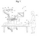
- FIG. 1is a schematic view of an embodiment of a surgical navigation system adapted to implement methods of the present disclosure
- FIGS. 2 and 2Aare flowcharts of registration procedures according to the present disclosure
- FIGS. 3A , 3 B, and 3 Cillustrate the development of additional spatial information for an anatomical structure represented by a first data set and the relation of such information to a second data set;
- FIG. 4Ais an example screen shot and FIGS. 4B and 4C are visual representations that depict data set collection and registration;
- FIG. 5illustrates the development of additional spatial information for a first anatomical structure and the relation of such information to a second anatomical structure that mirrors the first anatomical structure;
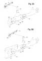
- FIGS. 6A and 6Bshow an example of an anatomical reference frame defined pre-operatively that is not accessible during a surgical procedure
- FIGS. 7A and 7Bshow an example of determining functional motion parameters of a hip of a patient.
- Systems and methods of the present disclosuremay be used to register different data sets related to one or more structures of a patient and/or to relate additional information from one such data set to another such data set, wherein the additional information may not be available or practically obtainable for the other data set.
- positional information of non-contiguous regions of a bodyis tied together without the need to identify or relate to local anatomical reference frames based on pre-defined anatomical landmarks.
- functional information from one data setis related to another data set to facilitate the performance of a functional assessment of a structure.
- the structurecan be an anatomical structure, such as a bone or joint of a patient
- the volume data setcan be an image data set of the bone or bones obtained using an ultrasound probe or other known imaging techniques of modalities.
- the functional information that is developed for the anatomical structure from a pre-operative image data setcan be related to an intra-operative image data set to aid in the planning and execution of surgical procedures and/or to facilitate early identification and prevention of certain diseases or harmful conditions.
- other informationcan be utilized, for example, to re-establish an anatomical reference frame that is accessible in one data set but not another.
- a further aspect of the present disclosureis the ability to register different data sets for a structure without a need for a predefined landmark or fiducial on the structure. Instead, arbitrary reference frames are established for different data sets and used to register such data sets.
- FIG. 1is a schematic view of a surgical navigation system 20 that is adapted to implement the steps of the procedure(s) disclosed herein.
- the surgical navigation system 20includes a display unit 22 , a computer system 24 , and a camera array 26 .
- the computer system 20is housed in a moveable cart 28 .
- the computer system 24may be, for example, any type of personal computer having a memory unit, a CPU, and a storage unit (all not shown), as would be apparent to one of ordinary skill in the art.
- the display unit 22can be any conventional display usable with the computer system 24 , such as a standard computer monitor or television.
- An exemplary surgical navigation systemis the Stryker Navigation system available from Stryker Corporation.
- the surgical navigation system 20is adapted to receive image data of a patient 30 .
- image datais obtained by an ultrasound probe 32 manipulated by a user 34 , such as a surgeon or a nurse, and transmitted wirelessly to the computer system 24 .
- a system that uses wires to transmit data between the ultrasound probe 32 and the computer system 24can be used.
- the ultrasound probe 32provides a non-invasive, non-ionizing, and portable imaging modality to obtain image data of the patient 30 .
- the ultrasound probe 32provides image data for underlying bones to overcome skin shift related motion artifacts.
- image datacan be collected using any other acceptable imaging technique or modality, such as magnetic resonance imaging (“MRI”), computed tomography (“CT”), single photon emission computed tomography, positron emission tomography, and the like.
- MRImagnetic resonance imaging
- CTcomputed tomography
- single photon emission computed tomographysingle photon emission computed tomography
- positron emission tomographyand the like.
- the camera array 26is adapted to detect the position of a sensor 36 coupled to the ultrasound probe 32 to track the position and orientation of such ultrasound probe 32 .
- the sensor 36can be one or more light emitting diodes (“LEDs”)
- the camera array 26can include a first camera 38 , a second camera 40 , and a third camera 42
- the first, second, and third cameras 38 , 40 , 42respectively, can be three CCD cameras that are adapted to detect infrared (“IR”) signals generated by the sensor 36 .
- IRinfrared
- the user 34can use other surgical tools and instruments that are capable of being tracked by the camera array 26 in the same manner as the ultrasound probe 32 .
- These additional surgical tools and instrumentsmay have sensors 36 that comprise, for example LEDs, either built into the tool or instrument or physically associated therewith in a known or determinable position and orientation sufficient for tracking the position of the instruments.
- the camera array 26is mounted on a rotatable arm 44 attached to the movable cart 28 so that the camera array 26 has a sufficient line of sight to a relevant field where a procedure is to take place.
- the camera array 26may be mounted onto an operating room wall (not shown) or onto another convenient surface or location.
- the surgical navigation system 20can be an active optical system that includes at least one infrared transceiver that is used to communicate data to and from the sensor 36 .
- the camera arrayincludes a first transceiver 46 and a second transceiver 48 located apart from each other. While the present disclosure is described using an active optical surgical navigation system, the systems and methods of the present disclosure can also be used with other surgical navigation technologies and systems, such as passive optical systems, magnetic based systems, inertial navigation based systems, and the like. Other computer-assisted systems also can be used including RFID based systems, video imaging based systems, and the like.
- the camera array 26is connected via a cable 50 to a localizer (not shown) or in some instances directly to the computer system 24 .
- the localizercooperates with the camera array 26 to identify the location and orientation of the sensor 36 on the ultrasound probe 32 within the line of sight of the camera array 26 .
- the localizerconverts raw position data of the LEDs into the orientation of individual LEDs of a plurality of LEDs that make up the sensor 36 and transmits this information to the computer system 24 .
- the localizerconverts raw position data of the LEDs into the position and orientation of the ultrasound probe 32 and transmits this information to the computer system 24 .
- a software program executed by the computer system 24can convert the raw data into the orientation of the ultrasound probe 32 .
- the conversion of the raw position datais well known to one skilled in the art.
- the computer system 24may optionally be controlled remotely by control buttons (not visible) located on the ultrasound probe 32 or otherwise easily accessible to the user 34 .
- the computer system 24also includes one or more input devices, such as a keyboard 52 , a mouse 54 , or any other input devices for operating the computer system 24 .
- methods of registering a first volume data set of an anatomical structure to a second volume data set of the anatomical structureis disclosed.
- the methodsare preferably performed using a computer surgical navigation system as disclosed herein, wherein the navigation system can track the position of one or more gathering devices for gathering the volume data sets, storing position data and extracting information therefrom, and correlating the position data with the volume data sets.
- FIG. 2describes a broad view of a method of registration, in which control initiates at a block 80 that collects a first data set for a structure, such as an anatomical structure of a patient. Following the block 80 , control passes to a block 82 that develops additional positional information related to the first data set, and a block 84 that determines or establishes a first reference frame for the first data set.
- the first reference frameis preferably an arbitrary reference frame.
- a block 86collects a second data set, a block 88 determines a second reference frame for the volume second data set. Thereafter, control passes to a block 90 that transforms the first reference frame into the second reference frame, and a block 92 relates the additional spatial information from the first reference frame, such as functional information for the anatomical structure, to the second reference frame.
- FIG. 2Adescribes a more detailed view of a method embodying the method of FIG. 2 , wherein control initiates a block 100 that collects a first data set for a structure, such as an anatomical structure of a patient.
- the first data setcan include a first volume data set for the anatomical structure.
- anatomical structurecan include an entire anatomical structural unit, such as a complete bone, and the term anatomical structure can include a smaller portion of the entire anatomical structural unit less than the entirety, such as just a small portion of the bone.
- the volume data setincludes information about the position and orientation of the anatomical structure, such as a bone or a joint.
- the first volume data setis collected using a subcutaneous imaging device, such as the tracked ultrasound probe 32 of FIG. 1 , wherein the volume data set includes an image of a bone or other subcutaneous structure on a patient.
- a subcutaneous imaging devicesuch as the tracked ultrasound probe 32 of FIG. 1
- Other image capturing devices and modalities for capturing the first image data setmay be used also, such as CT scan, MRI, X-rays, etc.
- the first volume data setmay be obtained pre-operatively, for example.
- the first volume data setpreferably includes image data regarding the anatomical structure, and may include two-dimensional (2D) image data and/or three-dimensional (3D) image data.
- One exemplary capturing device and modality for capturing the first image data setincludes a 2D or 3D ultrasound imaging device, if a 2D ultrasound probe is used, such probe can be used to collect volume data by collecting multiple slices of a region that includes the anatomical structure.
- the position of the capturing deviceis tracked by the surgical navigation system while capturing the volume data set.
- the anatomical structureis in a fixed position while the volume data set is captured, which dispenses with a need to track the position of the anatomical structure separately during the capturing.
- the anatomical structureoptionally may be tracked during the capturing, in which case the anatomical structure may move during the capturing and/or additional robustness may be incorporated into position data for the acquired volume data set encompassing the anatomical structure.
- the first reference frameis preferably an arbitrary reference frame established without reference to any pre-defined landmark, such as a fiducial or particular anatomical landmark, on the anatomical structure.
- the first reference framecan be of a camera assembly, an ultrasound probe, or the first volume data set itself, such as, a center of the first volume data set.
- Other ways to establish the arbitrary reference frame to distinguish from other types of reference framescan also be used.
- the reference framesmay be established by any known or commonly used image processing algorithms.
- the arbitrary reference framepreferably has a unique spatial relationship to the volume of the subject anatomical structure, such as a bone, and the arbitrary reference frame remains fixed in the same position relative thereto.
- Controlpasses to a block 104 that identifies an inherent feature of the first volume data set, such as a spatially unique physical spatial aspect of the volume data set.
- the inherent featurehas a unique position and orientation in relation to the anatomical structure that can be identified from any reference position.
- the computer system 24is adapted with appropriate command routines to calculate an image moment of inertia of the volume data set, which is constant with regard to the volume regardless of what point of view the volume is acquired or viewed from.
- Using the moment of inertiacan be advantageous because any given volume has a constant moment of inertia that has a unique fixed spatial relation to a data set representing a particular volume and regardless of the point of view from which the volume is viewed.
- the moment of inertia of a volume data set of a particular portion of a bonewill be in the same relative position to that portion of the bone regardless of from what position or point of view the volume data set is obtained.
- Other methods of determining a spatially unique physical spatial aspect of the volume data setmay be used and may obtain alternative or additional uniquely defined spatial information about the anatomical structure, such as surface contour information, point landmarks, etc., that could be used to define the arbitrary reference frame.
- the block 88correlates the first arbitrary reference frame and the image moment of inertia by a known unique spatial relationship therebetween, such as the xyz Cartesian coordinates of the image moment of inertia within the first arbitrary reference frame.
- the first arbitrary reference frameis assigned such that the moment of inertia defines an axis of the arbitrary reference frame.
- Other alternative and/or equivalent methods or systems for correlating the arbitrary reference frame to the spatially unique physical aspectmay be used.
- Controlpasses to a block 108 that develops and/or associates additional positional information with the first volume data set, wherein the additional spatial information has a unique spatial orientation relative to the first arbitrary reference frame.
- the additional positional informationcan include functional information for the anatomical structure, such as a gravity vector that acts on the anatomical structure and/or orientations of parts of the anatomical structure with respect to each other.
- the first data setis a pre-operative volume data set and the functional information is obtained for the anatomical structure when a patient is in a generally standing or upright position.
- the functional informationcan be obtained by other methods, as would be apparent to those skilled in the art.
- the additional spatial informationmay be contiguous with the first volume data set.
- the additional spatial informationmay include gravity vector information that defines a gravity vector through the first volume data set at the time the volume data set was obtained.
- the gravity vectormay be obtained by any known method.
- One such methodincludes having a gravity sensing device, such as an accelerometer, installed on the camera of the surgical navigation system, wherein the gravity sensing device identifies the local gravity vector while the first volume data set is being gathered.
- the gravity vector informationis then associated with the volume data set such that the gravity vector can be uniquely located with respect to the first arbitrary reference frame.
- the additional spatial information setmay be non-contiguous to the first volume data set.
- the additional spatial informationmay include a vector that identifies the location and orientation of another reference frame.
- the other reference framemay be another arbitrary reference frame for a non-contiguous volume data set that does not overlap with the first volume data set, wherein the non-contiguous volume data set relates to another anatomical structure or another portion of the same anatomical structure.
- the first volume data setmay be of a first portion of a bone and the non-contiguous volume data set may be of a second portion of the same bone.
- the other reference framemay also include a global reference frame that is common to several volume data sets, such as a camera reference frame of a camera of the surgical navigation system.
- the specific locations and/or orientations of reference frames of each of one or more non-contiguous volume data setsmay be interlinked with the first volume data set such that the location and orientation of any one or more of the volume data sets may be used to identify the location and orientation of one or more of the other non-contiguous volume data sets even though the volume data sets are not specifically overlapping and not presently viewed.
- additional spatial informationthat may have unique spatial characteristics in relation to the anatomical structure represented by the volume data set may also be identified with the volume data set.
- additional spatial informationcould include location and orientation vector(s) of the arbitrary reference frame of the volume data set with respect to other local anatomical reference frames of the patient, such as a pelvic plane, femoral mechanical axis, femoral anatomical axis, and other relevant local reference points and/or frame such as commonly used in the art.
- the disclosurecontemplates that any type of spatial information that has a unique identifiable spatial characteristic in relation to the anatomical structure represented by the volume data set may be associated with the volume data set as considered necessary or expedient for various and different specific applications.
- Controlpasses to a block 110 that collects a second data set.
- the second volume data setmay be of the same anatomical structure as for the first volume data set or at least have significant overlap therewith. There is sufficient overlap between the first data set and the second data set so that the first and second data sets can be registered in a subsequent step described hereinafter. In a preferred embodiment, there is at least about a seventy percent overlap of the anatomical structure captured in the first volume data set and the anatomical structure captured in the second volume data set. More than seventy percent overlap may be even more preferable in some instances, and less than seventy percent overlap may be sufficient in other instances.
- the second volume data setmay be obtained from a same point of view as the first volume data set or it may be obtained from a different point of view.
- the second volume data setmay be of a different anatomical structure that has some known or determinable spatial relationship to the first anatomical structure.
- the first volume data setmay be of a bone or portion thereof on one side of a patient's body and the second volume data may be of a bone or portion thereof on the opposite side of the patient's body that corresponds as a substantially mirror image of the first bone.
- the first volume data setmay include image data of a left femoral head and the second volume data set may include image data of a right femoral head.
- the left femoral headis assumed to be mathematically equivalent to a mirror image of the right femoral head in relation to a centerline of the body.
- the left femoral head and the right femoral headhave a known or determinable spatial relationship to each other about the centerline of the body.
- a prominent standard anatomical feature of the femoral headsuch as the lesser trochanter, may be identified as a landmark that is assumed to be in the same location on each of the left and right femurs but in mirror image relationship to each other about a centerline of the body.
- Other identifiable relationships between different anatomical structurescan also be identified and used in a similar manner as described herein.
- the second volume data setis obtained during a different portion of a procedure than the first volume data set, such as intra-operatively.
- the second data setis an intra-operative volume data set of the same bone or portion thereof that is obtained while the patient is anesthetized and lying on an operating table.
- the first and second volume data setscould be collected during the same portion of a surgical procedure, such as both being collected intra-operatively or both being collected pre-operatively.
- one or more volume data setsmay be collected post-operatively, such as to aid in post-operative diagnostics, for example.
- the second data setcan be collected using the same modality or a different modality than the first data set.
- both the first and second volume data setsare obtained using a 3D ultrasound imaging system having a tracking device attached thereto for being tracked by the surgical navigation system.
- the second data setis also collected using the ultrasound probe 32 tracked by the surgical navigation system 20 .
- the second reference framecan be an arbitrary reference frame and can be assigned or determined in a similar manner as described herein.
- the second arbitrary reference framepreferably is defined uniquely by the second volume data set.
- the second arbitrary reference frameis defined by the anatomical structure in the same manner as described previously herein with respect to the first anatomical structure.
- the second reference framecan be the same as or different from the first reference frame.
- Controlalso passes to a block 114 that identifies an inherent feature of the second volume data set, such as a spatially unique physical spatial aspect of the volume data set.
- an inherent feature of the second volume data setsuch as a spatially unique physical spatial aspect of the volume data set.
- the inherent feature of both volume data setsis preferably the same because the same anatomical feature would have the same unique spatial aspect, such as the image moment of inertia, for both the first and second volume data sets.
- the moment of inertia of the structureis constant and substantially unique relative to a given structure regardless of the point of view from which the structure is viewed.
- the moment of inertia of the same anatomical featureis uniquely identifiable in different volume data sets of the anatomical feature taken from different points of view.
- the second arbitrary reference framemay also be uniquely spatially associated with the image moment of inertia.
- a block 116correlates the second reference frame to the inherent feature of the second volume data set in the same manner as in block 106 or any sufficient manner.
- Controlpasses to a block 118 that registers the first reference frame into the second reference frame.
- the block 118performs data set matching, such as by finding the unique moment of inertia of each image and correlating the first and second arbitrary reference frames to each other based on matching the moment of inertia of the first volume data set to the moment of inertia of the second volume data set and calculating an appropriate transformation matrix therefrom.
- Another possible method of data set matchingmay include conducting a different volume data match of the first and second volume data sets, whereby first and second volume data sets are virtually overlaid and correlated to each other using any suitable or commonly known method.
- the registrationmay also be performed using other methods, such as volume-volume matching, surface-surface matching, and/or point-to-point matching.
- a mathematical transformation including rotation, translation, and scaleis calculated preferably by the computer system 24 that will register a common or assumed common spatially unique feature in the two volume data sets.
- the computer system 24then transforms one or both of the arbitrary reference frames to bring the spatially unique feature, and thus the volume data sets, into registration with each other.
- Other equally efficacious methods of calculating and performing a suitable transformation and registrationmay be used as would be known to a person skilled in the art.
- Controlpasses to a block 120 that relates the additional spatial information from the first reference frame, such as functional information for the anatomical structure, to the second reference frame.
- the additional spatial information from the first volume data setis related to the second arbitrary reference frame of the second volume data set after (or contemporaneously as) the first and second volume data sets have been brought into registration.
- the additional spatial informationis associated with the second arbitrary reference frame in correct registration therewith even though the additional spatial information is not directly available when the second volume data set is acquired.
- the additional spatial informationincludes the gravity vector as described above, the gravity vector is associated with and brought into registration with the second volume data set in proper orientation to the anatomical structure even when the anatomical structure is in a different orientation.
- the additional spatial informationincludes a vector that identifies the location and orientation of another reference frame as described above
- the location and orientation of the non-contiguous volume data sets not part of the second volume data setmay be identified based on the association and registration of the vector information comprising the additional spatial information.
- controlmay then pass to a block 122 that displays in registration with the second volume data set on a display device. Additional manipulations and uses of the additional spatial information may also be performed as desired.
- the blocks 100 - 122 described abovecan be rearranged, reordered, or modified by combining to include fewer or breaking down further additional steps, as would be apparent to one of skill in the art. As shown in FIG. 2A , the steps 100 - 122 in some instances correlate with the steps 80 - 92 shown in FIG. 2 , such as by being considered sub-steps thereof. Further, the logic represented by the flowcharts of FIGS. 2 and 2A can be implemented by any computer system that is adapted to implement the blocks 80 - 92 and/or 100 - 122 , such as the surgical navigation system 20 of FIG. 1 . In one embodiment, the computer system 24 includes appropriately programmed software and hardware to perform the blocks and processes of FIGS. 2 and 2A .
- FIGS. 3A , 3 B, and 3 Cillustrate an example where the additional spatial information includes functional information for an anatomical structure that is obtained from a pre-operative volume data set and related to an intra-operative volume data set so that the functional information can be used during a surgical procedure on a patient.
- a gravity vector that acts on the various bones that make up the hip jointcan be an important factor for the precise positioning of components of a prosthetic hip implant based on certain functional motion characteristics of the patient.
- functional informationmay be obtained for the anatomical structure in a plurality of different positions or over a period of time.
- functional informationcan be obtained for a knee joint in various positions to collect extension/flexion, varus/valgus, and other information for use during a surgical procedure.
- a prosthetic componentis placed accurately and effectively using the arbitrary reference frames discussed herein instead of relying on local biomechanical/anatomical references, such as a femur mechanical axis, pelvic frontal plane, or other standard local anatomical reference frames.
- a “local” reference frameis a reference frame based on specific accepted or pre-defined defined anatomical features of a patient, such as specific skeletal landmarks.
- an “arbitrary reference frame”refers to a reference frame that is identified uniquely based solely on the feature being looked at, such as the specific volume data set being viewed.
- the arbitrary reference frameis not dependent on locations of one or more specific pre-defined anatomical landmarks with respect to other portions of the anatomy but is correlated to and identifiable from unique spatial characteristics of only the anatomy of interest.
- Relating the functional information, such as the gravity vector G, to the intra-operative procedurefacilitates placement of correct prosthetic components in an optimal position and alignment based on the natural motion and movement patterns of the patient.
- the position and alignment of the prostheticcan further be optimized using a plurality of parameters that include, for example, joint specific anatomical and kinematic constraints, patient life-style specific activities, and prosthetic design specific geometrical and kinematic constrains. Still further optimization can be realized through incorporation of other relevant factors that arise or become visible intra-operatively, such as after the preparation of a joint surface to accept a prosthetic component.
- FIG. 3Cillustrates steps in one method and specific example that utilizes additional spatial information on a computer implemented surgical navigation system, such as the surgical navigation system 20 , including functional information relative to that shown in FIGS. 3A and 3B .
- a block 170acquires a pre-operative image volume data set 150 of a hip 152 or of parts of the hip of a patient 154 while the patient is standing.
- the image volume data set 150is acquired using the ultrasound probe 32 while being tracked by the camera array 26 to gather image data of the bones of interest in the hip joint, and the image data is stored in a suitable electronic memory available to the surgical navigation system.
- a block 172defines an arbitrary axis, such as an axis of the camera array, to the image volume data set 150 , identifies a unique spatial parameter of the image volume data set, and correlates the arbitrary axis to the spatial parameter.
- the unique spatial parameterpreferably includes the image moment of inertia of the image volume data set of the hip bones, calculated as discussed previously herein.
- the arbitrary axisis optionally also correlated to a local anatomical parameter of the hip 152 , such as a frontal plane 156 of the hip 152 as shown in FIG. 3 .
- a block 174assigns additional spatial information including functional information, such as a gravity vector G, to the image volume data set 150 .
- the gravity vector Gis shown pointing downwards to the floor in relation to the hip 152 in FIG. 3A because the patient is standing upright while the image volume data set 150 is obtained.
- the gravity vectoris acquired using an inertial system with an accelerometer, but can be acquired by any sufficient system known in the arts, such as a liquid level measurement system or other systems.
- the gravity vector Gis spatially assigned by determining an orientation of the gravity vector G with respect to the anatomical parameter and/or arbitrary axis, such as a specific tilt angle ⁇ with respect to the frontal plane 156 .
- anatomical parameterscan be defined, for example, a functional plane 158 , an iliac crest, a pubic symphesis, and the like, and various planes and angles defined thereby, wherein the gravity vector G can be related to such anatomical parameters.
- a block 176collects an intra-operative image volume data set 160 of the same general area while the patient 154 is lying in a generally prone position in a similar manner as with the block 170 .
- a block 178performs a data match to register the pre-operative image volume data set 150 and the intra-operative image volume data set 160 using any suitable data matching technique, such as image inertia matching or the volume data matching techniques discussed previously. Due to such registration, the gravity vector G is simultaneously or subsequently transferred to the intra-operative volume data set 160 for use during the procedure.
- any suitable data matching techniquesuch as image inertia matching or the volume data matching techniques discussed previously. Due to such registration, the gravity vector G is simultaneously or subsequently transferred to the intra-operative volume data set 160 for use during the procedure.
- a block 180displays the image volume data set 160 on the display unit 22 with the gravity vector G shown in registration with the bones of the hip.
- a replacement prosthesiscan then be aligned with the bones of the hip using the surgical navigation system 20 so as to have a relationship to the bones that has been preselected based on the position of the bones with respect to the gravity vector G.
- FIGS. 3A-3CThe method shown and described in relation to FIGS. 3A-3C is preferably implemented on the surgical navigation system 20 , and blocks 172 , 174 , 178 , and 180 are preferably performed by appropriate computer software routines associated with and preferably controlling the computer system 24 in any available manner known to one skilled in the art.
- FIGS. 4A-4Cillustrate an example of a volume data match registration procedure, wherein three data set collection screen shots are shown.
- a pre-operative volume data set 190 of a hip of a patientis collected by an ultrasound probe and shown on a display screen as shown in FIG. 4A , and a first arbitrary reference frame 192 is assigned thereto.
- additional spatial informationsuch as a gravity vector G, is associated in a unique spatial location with respect to the volume data set 190 .
- An intra-operative volume data set 194 of the hipis then collected, and a second arbitrary reference 196 frame is assigned thereto.
- the anatomical parameter of the hipincludes a right iliac crest 198 , a left iliac crest 200 , and a pubic symphesis 202 in the pre-operative volume data set.
- the same right and left iliac crests and pubic symphesisare also identified in the intra-operative volume data set 194 , wherein such structures in the pre-operative and intra-operative volume data sets can establish a unique arbitrary reference frame for the data sets.
- the image moment of inertiais calculated for each of the pre-operative and intra-operative volume data sets 190 , 194 such that the image moment of inertia of the pre-operative volume data set 190 is identical or sufficiently close to the same as the image moment of inertia of the intra-operative volume data set 194 .
- FIG. 4Bshows the pre-operative volume data set 190 and the intra-operative volume data set 194 of the hip overlapping before registration, such as with the first and second arbitrary reference frames 192 , 196 aligned and without being registered.
- the pre-operative data set 190 and intra-operative data set 194are then registered by a reference frame transfer by overlaying and correlating the reference frames of the respective data sets, as illustrated, for example, in FIG. 4C , which shows the pre-operative and intra-operative volume data sets 190 , 194 of the hip overlapping after registration.
- the transformation between the data setsis used to relate the additional spatial information, such as the gravity vector, from the pre-operative volume data set 190 to the intra-operative volume data set 194 .
- the gravity vector Gis determined with respect to an anatomical parameter of the hip in the pre-operative volume data set and assigned to the volume data set in unique spatial orientation thereto.
- FIGS. 3A-3C , and 4 A- 4 Cprovide an improvement over prior surgical procedures, which typically used the functional plane 158 as an approximation for the gravity vector G.
- the functional plane 158can be determined using known methods, for example, by determining an anterior superior iliac spine and by integration of a longitudinal body axes. While the functional plane 158 has provided a rather good approximation of the gravity vector, there is generally a difference of about 5° to about 10° between the orientation of the functional plane 158 and the gravity vector G. Therefore, detecting and assigning the gravity vector G is a much more accurate and reliable method for considering functional aspects of the patient during normal activity and movement parameters.
- an unaffected areais used to mirror an affected area to provide symmetrical biomechanical parameters, such as spatial relationships, angles, and biomechanical parameters, to repair the affected area.
- biomechanical parameterssuch as spatial relationships, angles, and biomechanical parameters
- FIG. 5in the case of a patient with a broken left femur, image data and functional information can be obtained for a healthy right femur of the patient.
- the functional information for the right femurcan be related to the broken left femur using the procedure of FIG. 2 to provide symmetrical biomechanical parameters to repair the broken left femur.
- data sets for both the right and left femursnormally are obtained intra-operatively due to the circumstances of typical trauma surgery, as would be apparent to one of ordinary skill in the art.
- a diagrammatic image data set 210 of a left femur 212 and a right femur 214shows that the left femur 212 has suffered some trauma, such as a severe fracture 216 across the femur neck and separating the left femur head 218 , while the right femur 214 is unaffected.
- the image data set 210can be obtained all at once by any suitable modality, such as with the ultrasound probe 32 and the surgical navigation system 20 as described earlier, and stored on the computer system 24 .
- the computer system 24then develops information for the left and right femurs 212 , 214 from the image data set 210 .
- the informationincludes a first volume data set 220 including the left femur head 218 and a second volume data set 222 including a part of the left femur body 224 .
- the volume data sets 220 and 222are preferably not contiguous to each other and/or are mathematically isolated from each other on opposite sides of the fracture 216 .
- the informationalso includes a third volume data set 226 including the unaffected right femur 214 .
- the third volume data set 226includes a volume data set 228 of the head of the right femur 214 and a noncontiguous volume data set 230 of a part of the right femur body.
- the right femur 214is preferably held immobile while the entirety of the volume data set 226 , including the volume data sets 228 and 230 , is obtained.
- a tracking device(not shown) may be attached to the femur 214 while the volume data set 226 is obtained in order to provide additional robustness to the position information of the volume data sets 228 and 230 relative to each other and/or correct for movement of the right femur while the volume data set 226 is obtained.
- Each volume data set 220 , 222 , 228 , and 230is assigned an arbitrary reference frame, 232 , 234 , 236 , and 238 , respectively.
- Each reference frame 232 , 234 , 236 , and 238preferably has a location and orientation that is correlated to a uniquely identifiable aspect of the volume data set, such as the image moment of inertia described herein.
- Additional spatial informationcomprising a vector 240 that uniquely defines the spatial relation, including position and orientation, of the volume data sets 222 and 230 to each other is established.
- the reference frames 236 and 238are spatially correlated with each other in a global reference frame 242 , such as of the camera array 26 , by the vector 240 even though the two volume data sets are not contiguous with each other.
- a global reference frame 242such as of the camera array 26
- Calculation of the additional vector 240may not be necessary or may be used to provide additional mathematical robustness by providing redundant measurements in an example where the volume data set 228 is contiguous with the volume data set 230 .
- the first volume data set 220 and the second volume data set 222 of the affected left femur 212are matched and registered with corresponding portions 228 and 230 , respectively, of the third volume data set 226 of the unaffected right femur 214 in order to determine a reconstructed position of the left femur head 218 and left femur body 224 that will match corresponding portions of the unaffected right femur 214 .
- the registration processesincludes performing a reference frame transfer from the reference frame of the unaffected right femur 214 to the reference frame of both volumes 220 and 222 of the affected left femur 212 .
- the shape and position of the left femur 212should be identical and a mirror image of the shape and position of the right femur 214 about a centerline therebetween. It is also assumed that the shapes of portions of the right femur 214 captured in the volume data sets 228 and 230 correspond substantially to the shapes of corresponding portions of the left femur 212 captured in the respective volume data sets 220 and 222 . With these assumptions, the reference frames 236 and 238 and corresponding volume data sets 228 and 230 and the vector 240 of the right femur 214 are mathematically mirrored about a centerline 244 to be in position to match the left femur 212 .
- volume data sets 220 or 222 of the left femur 212is then matched to with the corresponding mirrored volume data set 228 or 230 of the right femur 214 .
- the volume data sets 222 and 238may both include an easily identifiable three-dimensional feature, such as the lesser trochanter 246 , which can be used to register the volume data set 222 with the mirrored volume data set 238 .
- an image moment of inertiais calculated for both volume data sets 222 and 238 , and the image moment of inertias are then matched after mirroring the right femur information.
- Other methods of registering mirrored corresponding volume data setsmay also be used.
- the mirrored vector 240 ′ and volume data set 228define the theoretically correct position of the left femur head 218 in relation to the left femur body 224 .
- tracking devices 246 and 248are attached to each of the left femur body 224 and the left femur head 218 and independently tracked by the surgical navigation system 20 during the entire procedure. A surgeon is then able to adjust the pieces 218 and 224 of the left femur to align with the theoretically derived locations based on the registration to the mirrored volume data sets 228 , 230 of the right femur 214 .
- volume data sets 220 , 222 , 226 , 228 , and 230can be chosen arbitrarily. Therefore, time and computing resources are saved because there is no need to establish a local reference frame.
- the methodis not limited to work done on a femur as describe here, but can be used with minor modifications for any anatomical structure that is substantially mirrored on opposite sides of a centerline of a body, such as arms, ribs, feet, hands, hip, etc.
- the present disclosurealso contemplates the relation of spatial information from one data set relating to an anatomical structure at a first time to another data set of the same anatomical structure at another time, such as an anatomical reference frame.
- An exemplary situation shown in FIGS. 6A and 6Bis the ability to define an anatomical reference frame pre-operatively that is not accessible during a surgical procedure due to the positioning and draping of the patient on a surgical table.
- a pre-operative volume data set of a forearm 250including image data of the underlying bone(s), is collected using the tracked ultrasound probe 32 and surgical navigation system 20 at a stage when the forearm is accessible.
- a first volume data set 252 at one location of the forearm 250is obtained and a second volume data set 254 at another location of the forearm 250 is obtained when both locations are accessible, as shown in FIG. 6A .
- the pre-operative data setpreferably includes regions of the forearm 250 that will be accessible after the area of interest has been prepared and draped or will otherwise be inaccessible.
- An anatomical reference frame or other spatial informationsuch as a global reference frame 256 of the camera assembly 26 , is defined at a stage when the anatomy is accessible, and arbitrary reference frames 258 and 260 are defined for volume data sets 252 and 254 , respectively.
- Each reference frame 258 , 260is uniquely identifiable from the associated volume data set, such as by having a known relation to the image moment of inertia the respective volume data set 252 , 254 as discussed previously.
- the anatomical reference frame or other global reference frame 256is geometrically associated with the arbitrary reference frames 258 , 260 for the pre-operative data set, and a vector 262 is determined that associates the arbitrary reference frames 258 and 260 and the respective volume data sets 252 and 254 in a unique spatial position relative to each other.
- the portion of the forearm 250 corresponding to volume data set 254may not be accessible to the ultra sound probe 32 , such as due to draping as shown in FIG. 6B , or any other reason.
- a subsequent volume data set 252 ′ having substantial overlap with the volume data set 252is collected using the ultrasound probe 32 and surgical navigation system 20 , and the arbitrary reference frame 258 is re-established to relate the anatomical or global reference frame 256 to the subsequent volume data set 252 ′.
- the arbitrary reference frame 258can be re-established in any sufficient manner, such as by matching the image moment of inertia of the volume data sets 252 and 252 ′ in a substantially similar manner as described previously herein, by other volume matching or surface matching methods, etc.
- the computer system 24re-establishes the location of the second volume data set 254 based on the vector 262 using appropriate program routines even though that area of the forearm 250 is not accessible.
- the surgical navigation system 20is able to re-establish the locations of portions of the bones of the forearm 250 based on being able to view just one volume portion of the bone that was previously identified without having to either view the other volume portions that were previously identified or define local anatomical landmarks as discussed above.
- the example provided hereinmay be applied similarly to any anatomical feature that maintains a relatively stable structural geometry over time, such as any bone, and may be extended to apply to any number of spatially inter-connectable volume data sets.
- FIGS. 7A and 7Bfunctional information about an anatomical structure is developed by collecting a plurality of volume data sets of the same anatomical structure in a plurality of different positions at corresponding different times without the need to identify a local anatomical reference frame.
- FIGS. 7A and 7BOne example of this application is shown in FIGS. 7A and 7B , wherein functional motion parameters of a hip of a patient 270 are determined.
- a first volume data set 272is gathered of a portion 274 of the patient's femur
- a first volume set 276is gathered of a portion 278 of the pelvis, both with the patient's leg in an extended position.
- a second volume data set 272 ′is gathered of substantially the same portion of the patient's femur 274
- a second volume data set 276 ′is gathered of substantially the same portion 278 of the patient's pelvis, both with the patient's leg in a flexed position.
- Each volume data set 272 , 276 , 272 ′, and 276 ′is assigned an arbitrary reference frame 280 , 282 , 284 , and 286 , respectively, that is correlated to a known position in relation to a uniquely identifiable feature of the respective volume data set.
- each arbitrary reference frame 280 , 282 , 284 , and 286is correlated to an image moment of inertia of each volume data set 272 , 276 , 272 ′, and 276 ′, although other identifiable unique attributes of a particular volume data set could be used, as discussed herein.
- Additional positional informationincluding a vector 288 between the volume data sets 272 and 276 and a vector 288 ′ between the volume data sets 272 ′ and 276 ′ are calculated based on relation of the volume data sets to a global reference frame 290 , such as a reference frame of the camera array 26 .
- a gravity vector Gmay be correlated to one or more of the arbitrary reference frames 280 , 282 , 284 , and 286 , as described earlier.
- the reference frames of different volume data sets of the same volume, such as 272 and 272 ′,are registered with each other based on the uniquely identifiable feature of the volume in any suitable manner such as already discussed herein.
- the process of obtaining volume data sets of the same portion of the femur and the same portion of the pelviscan be repeated in several additional different positions, such as to define a movement cone of the hip under regular use conditions.
- the volume data sets 272 , 276 , 272 ′, and 276 ′preferably are obtained using one or more ultrasound probes 32 that are tracked by the camera array 26 of the surgical navigation system 20 in a manner as described previously.
- each of the volume data sets 272 , 276 , 272 ′, and 276 ′is obtained using only a single tracked ultrasound probe 32 .
- multiple tracked ultrasound probes 32are used simultaneously to continuously obtain simultaneous volume data sets of each anatomical structure as the patient's leg, for example, is moved in different positions.
- Functional motion parameters of the hip jointthat are spatially related to the various volume data sets, such as a range of motion cone and the gravity vector G, may then be calculated based on the various volume data sets without the necessity of defining and/or determining local anatomical reference frames based on predefined anatomical features.
- one or more computer systems 24 associated with the surgical navigation system 20perform the required calculations and store all associated data in memory associated therewith in a manner known in the art.
- the same or similar functional motion analysesmay be performed on other portions of the body as well in a similar manner.
- the methods and systems described hereincan facilitate the relation of information from one data set to another data set, wherein the information would not otherwise be available or easily obtainable in the other data set.
- the methods and systems disclosed hereinin many aspects advantageously utilize arbitrarily defined unique reference frames in different data sets to easily register the data sets and relate the information from one to another without requiring identification and use of specific landmarks that can be compared and/or matched across two or more data sets.
- Specific procedures that may benefit from the teachings disclosed hereininclude surgical procedures, such as joint arthroplasty to perform functional assessments during surgery and trauma surgery to mirror information from an unaffected anatomical structure to an affected anatomical structure.
Landscapes
- Health & Medical Sciences (AREA)
- Life Sciences & Earth Sciences (AREA)
- Engineering & Computer Science (AREA)
- Medical Informatics (AREA)
- Surgery (AREA)
- General Health & Medical Sciences (AREA)
- Public Health (AREA)
- Nuclear Medicine, Radiotherapy & Molecular Imaging (AREA)
- Veterinary Medicine (AREA)
- Animal Behavior & Ethology (AREA)
- Biomedical Technology (AREA)
- Heart & Thoracic Surgery (AREA)
- Molecular Biology (AREA)
- Pathology (AREA)
- Physics & Mathematics (AREA)
- Radiology & Medical Imaging (AREA)
- Biophysics (AREA)
- Oral & Maxillofacial Surgery (AREA)
- Primary Health Care (AREA)
- Epidemiology (AREA)
- Computer Vision & Pattern Recognition (AREA)
- Theoretical Computer Science (AREA)
- Dentistry (AREA)
- High Energy & Nuclear Physics (AREA)
- Optics & Photonics (AREA)
- Physiology (AREA)
- General Physics & Mathematics (AREA)
- Robotics (AREA)
- Urology & Nephrology (AREA)
- Pulmonology (AREA)
- Orthopedic Medicine & Surgery (AREA)
- Rheumatology (AREA)
- Apparatus For Radiation Diagnosis (AREA)
- Ultra Sonic Daignosis Equipment (AREA)
- Business, Economics & Management (AREA)
- Tourism & Hospitality (AREA)
- Child & Adolescent Psychology (AREA)
- Economics (AREA)
- Human Resources & Organizations (AREA)
- Marketing (AREA)
Abstract
Description
Claims (38)
Priority Applications (4)
| Application Number | Priority Date | Filing Date | Title |
|---|---|---|---|
| US12/835,384US8675939B2 (en) | 2010-07-13 | 2010-07-13 | Registration of anatomical data sets |
| DE102011106812.4ADE102011106812B4 (en) | 2010-07-13 | 2011-07-06 | registration of anatomical data sets |
| JP2011154736AJP2012020133A (en) | 2010-07-13 | 2011-07-13 | Device and method for registering anatomical structure data set |
| US14/100,055US9572548B2 (en) | 2010-07-13 | 2013-12-09 | Registration of anatomical data sets |
Applications Claiming Priority (1)
| Application Number | Priority Date | Filing Date | Title |
|---|---|---|---|
| US12/835,384US8675939B2 (en) | 2010-07-13 | 2010-07-13 | Registration of anatomical data sets |
Related Child Applications (1)
| Application Number | Title | Priority Date | Filing Date |
|---|---|---|---|
| US14/100,055ContinuationUS9572548B2 (en) | 2010-07-13 | 2013-12-09 | Registration of anatomical data sets |
Publications (2)
| Publication Number | Publication Date |
|---|---|
| US20120016269A1 US20120016269A1 (en) | 2012-01-19 |
| US8675939B2true US8675939B2 (en) | 2014-03-18 |
Family
ID=45403143
Family Applications (2)
| Application Number | Title | Priority Date | Filing Date |
|---|---|---|---|
| US12/835,384Active2032-09-23US8675939B2 (en) | 2010-07-13 | 2010-07-13 | Registration of anatomical data sets |
| US14/100,055Active2031-06-28US9572548B2 (en) | 2010-07-13 | 2013-12-09 | Registration of anatomical data sets |
Family Applications After (1)
| Application Number | Title | Priority Date | Filing Date |
|---|---|---|---|
| US14/100,055Active2031-06-28US9572548B2 (en) | 2010-07-13 | 2013-12-09 | Registration of anatomical data sets |
Country Status (3)
| Country | Link |
|---|---|
| US (2) | US8675939B2 (en) |
| JP (1) | JP2012020133A (en) |
| DE (1) | DE102011106812B4 (en) |
Cited By (147)
| Publication number | Priority date | Publication date | Assignee | Title |
|---|---|---|---|---|
| US20120203140A1 (en)* | 2011-02-08 | 2012-08-09 | Henrik Malchau | Patient Positioning Systems and Methods |
| US20130070979A1 (en)* | 2011-09-16 | 2013-03-21 | Searete Llc, A Limited Liability Corporation Of The State Of Delaware | Registering regions of interest of a body part to a coordinate system |
| US20130094738A1 (en)* | 2011-10-14 | 2013-04-18 | Sarah Bond | Methods and apparatus for aligning sets of medical imaging data |
| US20130102893A1 (en)* | 2010-06-30 | 2013-04-25 | Fritz Vollmer | Medical image registration using a rigid inner body surface |
| US20130202174A1 (en)* | 2012-02-06 | 2013-08-08 | Samsung Medison Co., Ltd. | Method and apparatus for obtaining symmetry information of objects |
| US20140112529A1 (en)* | 2012-10-24 | 2014-04-24 | Samsung Electronics Co., Ltd. | Method, apparatus, and system for correcting medical image according to patient's pose variation |
| US20150190107A1 (en)* | 2014-01-08 | 2015-07-09 | Samsung Electronics Co., Ltd. | Apparatus for generating image and control method thereof |
| US9078685B2 (en) | 2007-02-16 | 2015-07-14 | Globus Medical, Inc. | Method and system for performing invasive medical procedures using a surgical robot |
| US9713506B2 (en) | 2014-10-29 | 2017-07-25 | Intellijoint Surgical Inc. | Systems, methods and devices for image registration and surgical localization |
| US9782229B2 (en) | 2007-02-16 | 2017-10-10 | Globus Medical, Inc. | Surgical robot platform |
| US10080615B2 (en) | 2015-08-12 | 2018-09-25 | Globus Medical, Inc. | Devices and methods for temporary mounting of parts to bone |
| WO2018189725A1 (en) | 2017-04-14 | 2018-10-18 | Stryker Corporation | Surgical systems and methods for facilitating ad-hoc intraoperative planning of surgical procedures |
| US10117632B2 (en) | 2016-02-03 | 2018-11-06 | Globus Medical, Inc. | Portable medical imaging system with beam scanning collimator |
| US10136954B2 (en) | 2012-06-21 | 2018-11-27 | Globus Medical, Inc. | Surgical tool systems and method |
| WO2018227095A2 (en) | 2017-06-09 | 2018-12-13 | Mako Surgical Corp. | Systems and tools for positioning workpieces with surgical robots |
| US10231791B2 (en) | 2012-06-21 | 2019-03-19 | Globus Medical, Inc. | Infrared signal based position recognition system for use with a robot-assisted surgery |
| EP3482710A1 (en) | 2017-11-14 | 2019-05-15 | Stryker Corporation | Patient-specific preoperative planning simulation techniques |
| US10292778B2 (en) | 2014-04-24 | 2019-05-21 | Globus Medical, Inc. | Surgical instrument holder for use with a robotic surgical system |
| US10357184B2 (en) | 2012-06-21 | 2019-07-23 | Globus Medical, Inc. | Surgical tool systems and method |
| WO2019147948A1 (en) | 2018-01-26 | 2019-08-01 | Mako Surgical Corp. | End effectors, systems, and methods for impacting prosthetics guided by surgical robots |
| US10426429B2 (en) | 2015-10-08 | 2019-10-01 | Decision Sciences Medical Company, LLC | Acoustic orthopedic tracking system and methods |
| US10448910B2 (en) | 2016-02-03 | 2019-10-22 | Globus Medical, Inc. | Portable medical imaging system |
| US10573023B2 (en) | 2018-04-09 | 2020-02-25 | Globus Medical, Inc. | Predictive visualization of medical imaging scanner component movement |
| US10569794B2 (en) | 2015-10-13 | 2020-02-25 | Globus Medical, Inc. | Stabilizer wheel assembly and methods of use |
| US10580217B2 (en) | 2015-02-03 | 2020-03-03 | Globus Medical, Inc. | Surgeon head-mounted display apparatuses |
| US10646283B2 (en) | 2018-02-19 | 2020-05-12 | Globus Medical Inc. | Augmented reality navigation systems for use with robotic surgical systems and methods of their use |
| US10660712B2 (en) | 2011-04-01 | 2020-05-26 | Globus Medical Inc. | Robotic system and method for spinal and other surgeries |
| US10675094B2 (en) | 2017-07-21 | 2020-06-09 | Globus Medical Inc. | Robot surgical platform |
| EP3692939A1 (en) | 2019-02-07 | 2020-08-12 | Stryker European Operations Limited | Surgical systems for facilitating tissue treatment |
| US10743838B2 (en) | 2015-02-25 | 2020-08-18 | Decision Sciences Medical Company, LLC | Acoustic signal transmission couplants and coupling mediums |
| US10813704B2 (en) | 2013-10-04 | 2020-10-27 | Kb Medical, Sa | Apparatus and systems for precise guidance of surgical tools |
| US10842453B2 (en) | 2016-02-03 | 2020-11-24 | Globus Medical, Inc. | Portable medical imaging system |
| US10866119B2 (en) | 2016-03-14 | 2020-12-15 | Globus Medical, Inc. | Metal detector for detecting insertion of a surgical device into a hollow tube |
| US10893912B2 (en) | 2006-02-16 | 2021-01-19 | Globus Medical Inc. | Surgical tool systems and methods |
| US10898252B2 (en) | 2017-11-09 | 2021-01-26 | Globus Medical, Inc. | Surgical robotic systems for bending surgical rods, and related methods and devices |
| US10925681B2 (en) | 2015-07-31 | 2021-02-23 | Globus Medical Inc. | Robot arm and methods of use |
| US10939968B2 (en) | 2014-02-11 | 2021-03-09 | Globus Medical Inc. | Sterile handle for controlling a robotic surgical system from a sterile field |
| US10945742B2 (en) | 2014-07-14 | 2021-03-16 | Globus Medical Inc. | Anti-skid surgical instrument for use in preparing holes in bone tissue |
| WO2021067597A1 (en) | 2019-10-01 | 2021-04-08 | Mako Surgical Corp. | Surgical systems for guiding robotic manipulators |
| US10973594B2 (en) | 2015-09-14 | 2021-04-13 | Globus Medical, Inc. | Surgical robotic systems and methods thereof |
| US10993699B2 (en) | 2011-10-28 | 2021-05-04 | Decision Sciences International Corporation | Spread spectrum coded waveforms in ultrasound diagnostics |
| US11045179B2 (en) | 2019-05-20 | 2021-06-29 | Global Medical Inc | Robot-mounted retractor system |
| US11045267B2 (en) | 2012-06-21 | 2021-06-29 | Globus Medical, Inc. | Surgical robotic automation with tracking markers |
| US11058378B2 (en) | 2016-02-03 | 2021-07-13 | Globus Medical, Inc. | Portable medical imaging system |
| US11096661B2 (en) | 2013-09-13 | 2021-08-24 | Decision Sciences International Corporation | Coherent spread-spectrum coded waveforms in synthetic aperture image formation |
| US11109922B2 (en) | 2012-06-21 | 2021-09-07 | Globus Medical, Inc. | Surgical tool systems and method |
| US11116576B2 (en) | 2012-06-21 | 2021-09-14 | Globus Medical Inc. | Dynamic reference arrays and methods of use |
| US11134862B2 (en) | 2017-11-10 | 2021-10-05 | Globus Medical, Inc. | Methods of selecting surgical implants and related devices |
| US11153555B1 (en) | 2020-05-08 | 2021-10-19 | Globus Medical Inc. | Extended reality headset camera system for computer assisted navigation in surgery |
| US11154274B2 (en) | 2019-04-23 | 2021-10-26 | Decision Sciences Medical Company, LLC | Semi-rigid acoustic coupling articles for ultrasound diagnostic and treatment applications |
| US11172995B2 (en) | 2015-05-29 | 2021-11-16 | Smith & Nephew, Inc. | Method for registering articulated anatomical structures |
| US11207150B2 (en) | 2020-02-19 | 2021-12-28 | Globus Medical, Inc. | Displaying a virtual model of a planned instrument attachment to ensure correct selection of physical instrument attachment |
| US11253216B2 (en) | 2020-04-28 | 2022-02-22 | Globus Medical Inc. | Fixtures for fluoroscopic imaging systems and related navigation systems and methods |
| US11253327B2 (en) | 2012-06-21 | 2022-02-22 | Globus Medical, Inc. | Systems and methods for automatically changing an end-effector on a surgical robot |
| US11266470B2 (en) | 2015-02-18 | 2022-03-08 | KB Medical SA | Systems and methods for performing minimally invasive spinal surgery with a robotic surgical system using a percutaneous technique |
| US11278360B2 (en) | 2018-11-16 | 2022-03-22 | Globus Medical, Inc. | End-effectors for surgical robotic systems having sealed optical components |
| US11298196B2 (en) | 2012-06-21 | 2022-04-12 | Globus Medical Inc. | Surgical robotic automation with tracking markers and controlled tool advancement |
| US11317973B2 (en) | 2020-06-09 | 2022-05-03 | Globus Medical, Inc. | Camera tracking bar for computer assisted navigation during surgery |
| US11317971B2 (en) | 2012-06-21 | 2022-05-03 | Globus Medical, Inc. | Systems and methods related to robotic guidance in surgery |
| US11317978B2 (en) | 2019-03-22 | 2022-05-03 | Globus Medical, Inc. | System for neuronavigation registration and robotic trajectory guidance, robotic surgery, and related methods and devices |
| US11337742B2 (en) | 2018-11-05 | 2022-05-24 | Globus Medical Inc | Compliant orthopedic driver |
| US11337769B2 (en) | 2015-07-31 | 2022-05-24 | Globus Medical, Inc. | Robot arm and methods of use |
| US11357548B2 (en) | 2017-11-09 | 2022-06-14 | Globus Medical, Inc. | Robotic rod benders and related mechanical and motor housings |
| US11382700B2 (en) | 2020-05-08 | 2022-07-12 | Globus Medical Inc. | Extended reality headset tool tracking and control |
| US11382549B2 (en) | 2019-03-22 | 2022-07-12 | Globus Medical, Inc. | System for neuronavigation registration and robotic trajectory guidance, and related methods and devices |
| US11382713B2 (en) | 2020-06-16 | 2022-07-12 | Globus Medical, Inc. | Navigated surgical system with eye to XR headset display calibration |
| US11382699B2 (en) | 2020-02-10 | 2022-07-12 | Globus Medical Inc. | Extended reality visualization of optical tool tracking volume for computer assisted navigation in surgery |
| US11395706B2 (en) | 2012-06-21 | 2022-07-26 | Globus Medical Inc. | Surgical robot platform |
| US11399900B2 (en) | 2012-06-21 | 2022-08-02 | Globus Medical, Inc. | Robotic systems providing co-registration using natural fiducials and related methods |
| US11419616B2 (en) | 2019-03-22 | 2022-08-23 | Globus Medical, Inc. | System for neuronavigation registration and robotic trajectory guidance, robotic surgery, and related methods and devices |
| US11426178B2 (en) | 2019-09-27 | 2022-08-30 | Globus Medical Inc. | Systems and methods for navigating a pin guide driver |
| US11439444B1 (en) | 2021-07-22 | 2022-09-13 | Globus Medical, Inc. | Screw tower and rod reduction tool |
| US11510750B2 (en) | 2020-05-08 | 2022-11-29 | Globus Medical, Inc. | Leveraging two-dimensional digital imaging and communication in medicine imagery in three-dimensional extended reality applications |
| US11510684B2 (en) | 2019-10-14 | 2022-11-29 | Globus Medical, Inc. | Rotary motion passive end effector for surgical robots in orthopedic surgeries |
| US11520043B2 (en) | 2020-11-13 | 2022-12-06 | Decision Sciences Medical Company, LLC | Systems and methods for synthetic aperture ultrasound imaging of an object |
| US11523785B2 (en) | 2020-09-24 | 2022-12-13 | Globus Medical, Inc. | Increased cone beam computed tomography volume length without requiring stitching or longitudinal C-arm movement |
| US11529195B2 (en) | 2017-01-18 | 2022-12-20 | Globus Medical Inc. | Robotic navigation of robotic surgical systems |
| US11571265B2 (en) | 2019-03-22 | 2023-02-07 | Globus Medical Inc. | System for neuronavigation registration and robotic trajectory guidance, robotic surgery, and related methods and devices |
| US11571171B2 (en) | 2019-09-24 | 2023-02-07 | Globus Medical, Inc. | Compound curve cable chain |
| US11602402B2 (en) | 2018-12-04 | 2023-03-14 | Globus Medical, Inc. | Drill guide fixtures, cranial insertion fixtures, and related methods and robotic systems |
| US11607149B2 (en) | 2012-06-21 | 2023-03-21 | Globus Medical Inc. | Surgical tool systems and method |
| US11628023B2 (en) | 2019-07-10 | 2023-04-18 | Globus Medical, Inc. | Robotic navigational system for interbody implants |
| US11628039B2 (en) | 2006-02-16 | 2023-04-18 | Globus Medical Inc. | Surgical tool systems and methods |
| US11717350B2 (en) | 2020-11-24 | 2023-08-08 | Globus Medical Inc. | Methods for robotic assistance and navigation in spinal surgery and related systems |
| US11737831B2 (en) | 2020-09-02 | 2023-08-29 | Globus Medical Inc. | Surgical object tracking template generation for computer assisted navigation during surgical procedure |
| US11737766B2 (en) | 2014-01-15 | 2023-08-29 | Globus Medical Inc. | Notched apparatus for guidance of an insertable instrument along an axis during spinal surgery |
| US11744655B2 (en) | 2018-12-04 | 2023-09-05 | Globus Medical, Inc. | Drill guide fixtures, cranial insertion fixtures, and related methods and robotic systems |
| US11793588B2 (en) | 2020-07-23 | 2023-10-24 | Globus Medical, Inc. | Sterile draping of robotic arms |
| US11793570B2 (en) | 2012-06-21 | 2023-10-24 | Globus Medical Inc. | Surgical robotic automation with tracking markers |
| US11794338B2 (en) | 2017-11-09 | 2023-10-24 | Globus Medical Inc. | Robotic rod benders and related mechanical and motor housings |
| US11793574B2 (en) | 2020-03-16 | 2023-10-24 | Stryker Australia Pty Ltd | Automated cut planning for removal of diseased regions |
| US11806084B2 (en) | 2019-03-22 | 2023-11-07 | Globus Medical, Inc. | System for neuronavigation registration and robotic trajectory guidance, and related methods and devices |
| US11813030B2 (en) | 2017-03-16 | 2023-11-14 | Globus Medical, Inc. | Robotic navigation of robotic surgical systems |
| US11819365B2 (en) | 2012-06-21 | 2023-11-21 | Globus Medical, Inc. | System and method for measuring depth of instrumentation |
| US11850009B2 (en) | 2021-07-06 | 2023-12-26 | Globus Medical, Inc. | Ultrasonic robotic surgical navigation |
| US11857266B2 (en) | 2012-06-21 | 2024-01-02 | Globus Medical, Inc. | System for a surveillance marker in robotic-assisted surgery |
| US11857149B2 (en) | 2012-06-21 | 2024-01-02 | Globus Medical, Inc. | Surgical robotic systems with target trajectory deviation monitoring and related methods |
| US11864857B2 (en) | 2019-09-27 | 2024-01-09 | Globus Medical, Inc. | Surgical robot with passive end effector |
| US11864839B2 (en) | 2012-06-21 | 2024-01-09 | Globus Medical Inc. | Methods of adjusting a virtual implant and related surgical navigation systems |
| US11864745B2 (en) | 2012-06-21 | 2024-01-09 | Globus Medical, Inc. | Surgical robotic system with retractor |
| US11871998B2 (en) | 2019-12-06 | 2024-01-16 | Stryker European Operations Limited | Gravity based patient image orientation detection |
| US11872000B2 (en) | 2015-08-31 | 2024-01-16 | Globus Medical, Inc | Robotic surgical systems and methods |
| US11877807B2 (en) | 2020-07-10 | 2024-01-23 | Globus Medical, Inc | Instruments for navigated orthopedic surgeries |
| US11883217B2 (en) | 2016-02-03 | 2024-01-30 | Globus Medical, Inc. | Portable medical imaging system and method |
| US11890066B2 (en) | 2019-09-30 | 2024-02-06 | Globus Medical, Inc | Surgical robot with passive end effector |
| US11911225B2 (en) | 2012-06-21 | 2024-02-27 | Globus Medical Inc. | Method and system for improving 2D-3D registration convergence |
| US11911115B2 (en) | 2021-12-20 | 2024-02-27 | Globus Medical Inc. | Flat panel registration fixture and method of using same |
| US11911112B2 (en) | 2020-10-27 | 2024-02-27 | Globus Medical, Inc. | Robotic navigational system |
| US11941814B2 (en) | 2020-11-04 | 2024-03-26 | Globus Medical Inc. | Auto segmentation using 2-D images taken during 3-D imaging spin |
| US11944325B2 (en) | 2019-03-22 | 2024-04-02 | Globus Medical, Inc. | System for neuronavigation registration and robotic trajectory guidance, robotic surgery, and related methods and devices |
| US11974822B2 (en) | 2012-06-21 | 2024-05-07 | Globus Medical Inc. | Method for a surveillance marker in robotic-assisted surgery |
| US11974886B2 (en) | 2016-04-11 | 2024-05-07 | Globus Medical Inc. | Surgical tool systems and methods |
| US11992373B2 (en) | 2019-12-10 | 2024-05-28 | Globus Medical, Inc | Augmented reality headset with varied opacity for navigated robotic surgery |
| US12004905B2 (en) | 2012-06-21 | 2024-06-11 | Globus Medical, Inc. | Medical imaging systems using robotic actuators and related methods |
| US12017389B2 (en) | 2019-03-06 | 2024-06-25 | Decision Sciences Medical Company, LLC | Methods for manufacturing and distributing semi-rigid acoustic coupling articles and packaging for ultrasound imaging |
| US12048493B2 (en) | 2022-03-31 | 2024-07-30 | Globus Medical, Inc. | Camera tracking system identifying phantom markers during computer assisted surgery navigation |
| US12064189B2 (en) | 2019-12-13 | 2024-08-20 | Globus Medical, Inc. | Navigated instrument for use in robotic guided surgery |
| US12070276B2 (en) | 2020-06-09 | 2024-08-27 | Globus Medical Inc. | Surgical object tracking in visible light via fiducial seeding and synthetic image registration |
| US12070286B2 (en) | 2021-01-08 | 2024-08-27 | Globus Medical, Inc | System and method for ligament balancing with robotic assistance |
| US12076091B2 (en) | 2020-10-27 | 2024-09-03 | Globus Medical, Inc. | Robotic navigational system |
| US12082886B2 (en) | 2017-04-05 | 2024-09-10 | Globus Medical Inc. | Robotic surgical systems for preparing holes in bone tissue and methods of their use |
| US12103480B2 (en) | 2022-03-18 | 2024-10-01 | Globus Medical Inc. | Omni-wheel cable pusher |
| US12133772B2 (en) | 2019-12-10 | 2024-11-05 | Globus Medical, Inc. | Augmented reality headset for navigated robotic surgery |
| US12150728B2 (en) | 2021-04-14 | 2024-11-26 | Globus Medical, Inc. | End effector for a surgical robot |
| US12161427B2 (en) | 2022-06-08 | 2024-12-10 | Globus Medical, Inc. | Surgical navigation system with flat panel registration fixture |
| US12184636B2 (en) | 2021-10-04 | 2024-12-31 | Globus Medical, Inc. | Validating credential keys based on combinations of credential value strings and input order strings |
| US12178523B2 (en) | 2021-04-19 | 2024-12-31 | Globus Medical, Inc. | Computer assisted surgical navigation system for spine procedures |
| US12201375B2 (en) | 2021-09-16 | 2025-01-21 | Globus Medical Inc. | Extended reality systems for visualizing and controlling operating room equipment |
| US12220120B2 (en) | 2012-06-21 | 2025-02-11 | Globus Medical, Inc. | Surgical robotic system with retractor |
| US12220176B2 (en) | 2019-12-10 | 2025-02-11 | Globus Medical, Inc. | Extended reality instrument interaction zone for navigated robotic |
| US12226169B2 (en) | 2022-07-15 | 2025-02-18 | Globus Medical, Inc. | Registration of 3D and 2D images for surgical navigation and robotic guidance without using radiopaque fiducials in the images |
| US12238087B2 (en) | 2021-10-04 | 2025-02-25 | Globus Medical, Inc. | Validating credential keys based on combinations of credential value strings and input order strings |
| US12232820B2 (en) | 2021-12-01 | 2025-02-25 | Globus Medical, Inc. | Extended reality systems with three-dimensional visualizations of medical image scan slices |
| US12251140B2 (en) | 2012-06-21 | 2025-03-18 | Globus Medical, Inc. | Methods for performing medical procedures using a surgical robot |
| US12262954B2 (en) | 2012-06-21 | 2025-04-01 | Globus Medical, Inc. | Surgical robotic automation with tracking markers |
| US12310683B2 (en) | 2012-06-21 | 2025-05-27 | Globus Medical, Inc. | Surgical tool systems and method |
| US12318150B2 (en) | 2022-10-11 | 2025-06-03 | Globus Medical Inc. | Camera tracking system for computer assisted surgery navigation |
| US12329593B2 (en) | 2012-06-21 | 2025-06-17 | Globus Medical, Inc. | Surgical robotic automation with tracking markers |
| US12329391B2 (en) | 2019-09-27 | 2025-06-17 | Globus Medical, Inc. | Systems and methods for robot-assisted knee arthroplasty surgery |
| US12329469B2 (en) | 2014-12-02 | 2025-06-17 | Globus Medical Inc. | Robot assisted volume removal during surgery |
| US12354263B2 (en) | 2022-07-15 | 2025-07-08 | Globus Medical Inc. | Registration of 3D and 2D images for surgical navigation and robotic guidance without using radiopaque fiducials in the images |
| US12394086B2 (en) | 2022-05-10 | 2025-08-19 | Globus Medical, Inc. | Accuracy check and automatic calibration of tracked instruments |
| US12396692B2 (en) | 2019-09-24 | 2025-08-26 | Globus Medical, Inc. | Compound curve cable chain |
| US12408929B2 (en) | 2019-09-27 | 2025-09-09 | Globus Medical, Inc. | Systems and methods for navigating a pin guide driver |
| US12414752B2 (en) | 2020-02-17 | 2025-09-16 | Globus Medical, Inc. | System and method of determining optimal 3-dimensional position and orientation of imaging device for imaging patient bones |
| US12430760B2 (en) | 2021-10-20 | 2025-09-30 | Globus Medical, Inc. | Registering intra-operative images transformed from pre-operative images of different imaging-modality for computer assisted navigation during surgery |
| US12444045B2 (en) | 2022-05-12 | 2025-10-14 | Globus Medical, Inc. | Interpolation of medical images |
Families Citing this family (71)
| Publication number | Priority date | Publication date | Assignee | Title |
|---|---|---|---|---|
| US8784336B2 (en) | 2005-08-24 | 2014-07-22 | C. R. Bard, Inc. | Stylet apparatuses and methods of manufacture |
| US7794407B2 (en) | 2006-10-23 | 2010-09-14 | Bard Access Systems, Inc. | Method of locating the tip of a central venous catheter |
| US8388546B2 (en) | 2006-10-23 | 2013-03-05 | Bard Access Systems, Inc. | Method of locating the tip of a central venous catheter |
| US10449330B2 (en) | 2007-11-26 | 2019-10-22 | C. R. Bard, Inc. | Magnetic element-equipped needle assemblies |
| US10524691B2 (en) | 2007-11-26 | 2020-01-07 | C. R. Bard, Inc. | Needle assembly including an aligned magnetic element |
| US9649048B2 (en) | 2007-11-26 | 2017-05-16 | C. R. Bard, Inc. | Systems and methods for breaching a sterile field for intravascular placement of a catheter |
| US9636031B2 (en) | 2007-11-26 | 2017-05-02 | C.R. Bard, Inc. | Stylets for use with apparatus for intravascular placement of a catheter |
| US8849382B2 (en) | 2007-11-26 | 2014-09-30 | C. R. Bard, Inc. | Apparatus and display methods relating to intravascular placement of a catheter |
| US9521961B2 (en) | 2007-11-26 | 2016-12-20 | C. R. Bard, Inc. | Systems and methods for guiding a medical instrument |
| ES2465915T3 (en) | 2007-11-26 | 2014-06-09 | C.R. Bard, Inc. | Integrated system for intravascular catheter placement |
| US10751509B2 (en) | 2007-11-26 | 2020-08-25 | C. R. Bard, Inc. | Iconic representations for guidance of an indwelling medical device |
| US8781555B2 (en) | 2007-11-26 | 2014-07-15 | C. R. Bard, Inc. | System for placement of a catheter including a signal-generating stylet |
| US9901714B2 (en) | 2008-08-22 | 2018-02-27 | C. R. Bard, Inc. | Catheter assembly including ECG sensor and magnetic assemblies |
| US8437833B2 (en) | 2008-10-07 | 2013-05-07 | Bard Access Systems, Inc. | Percutaneous magnetic gastrostomy |
| US8588892B2 (en)* | 2008-12-02 | 2013-11-19 | Avenir Medical Inc. | Method and system for aligning a prosthesis during surgery using active sensors |
| JP5795576B2 (en) | 2009-06-12 | 2015-10-14 | バード・アクセス・システムズ,インコーポレーテッド | Method of operating a computer-based medical device that uses an electrocardiogram (ECG) signal to position an intravascular device in or near the heart |
| US9532724B2 (en) | 2009-06-12 | 2017-01-03 | Bard Access Systems, Inc. | Apparatus and method for catheter navigation using endovascular energy mapping |
| EP2464407A4 (en) | 2009-08-10 | 2014-04-02 | Bard Access Systems Inc | Devices and methods for endovascular electrography |
| WO2011097312A1 (en) | 2010-02-02 | 2011-08-11 | C.R. Bard, Inc. | Apparatus and method for catheter navigation and tip location |
| EP2912999B1 (en) | 2010-05-28 | 2022-06-29 | C. R. Bard, Inc. | Apparatus for use with needle insertion guidance system |
| EP4122385A1 (en) | 2010-05-28 | 2023-01-25 | C. R. Bard, Inc. | Insertion guidance system for needles and medical components |
| BR112013002431B1 (en) | 2010-08-20 | 2021-06-29 | C.R. Bard, Inc | SYSTEM FOR RECONFIRMING THE POSITION OF A CATHETER INSIDE A PATIENT |
| US8801693B2 (en) | 2010-10-29 | 2014-08-12 | C. R. Bard, Inc. | Bioimpedance-assisted placement of a medical device |
| KR20130129246A (en)* | 2010-12-17 | 2013-11-27 | 아브니르 메디컬 아이엔씨. | Method and system for aligning a prosthesis during surgery |
| US9020229B2 (en)* | 2011-05-13 | 2015-04-28 | Broncus Medical, Inc. | Surgical assistance planning method using lung motion analysis |
| CN103764061B (en) | 2011-06-27 | 2017-03-08 | 内布拉斯加大学评议会 | On Tool Tracking System and Computer Assisted Surgery Method |
| US9498231B2 (en) | 2011-06-27 | 2016-11-22 | Board Of Regents Of The University Of Nebraska | On-board tool tracking system and methods of computer assisted surgery |
| RU2609203C2 (en) | 2011-07-06 | 2017-01-30 | Си.Ар. Бард, Инк. | Determination and calibration of needle length for needle guidance system |
| US10740772B2 (en)* | 2011-07-25 | 2020-08-11 | Prevedere, Inc. | Systems and methods for forecasting based upon time series data |
| US10896388B2 (en) | 2011-07-25 | 2021-01-19 | Prevedere, Inc. | Systems and methods for business analytics management and modeling |
| US8933935B2 (en)* | 2011-11-10 | 2015-01-13 | 7D Surgical Inc. | Method of rendering and manipulating anatomical images on mobile computing device |
| JP5908790B2 (en)* | 2012-05-28 | 2016-04-26 | ジーイー・メディカル・システムズ・グローバル・テクノロジー・カンパニー・エルエルシー | Ultrasonic image display device and control program thereof |
| CN104379064B (en)* | 2012-06-27 | 2017-09-15 | 东芝医疗系统株式会社 | Ultrasonic diagnostic apparatus and correction method of image data |
| CA2878861A1 (en)* | 2012-07-12 | 2014-01-16 | Ao Technology Ag | Method for generating a graphical 3d computer model of at least one anatomical structure in a selectable pre-, intra-, or postoperative status |
| US11995667B2 (en) | 2012-07-25 | 2024-05-28 | Prevedere Inc. | Systems and methods for business analytics model scoring and selection |
| US9402637B2 (en) | 2012-10-11 | 2016-08-02 | Howmedica Osteonics Corporation | Customized arthroplasty cutting guides and surgical methods using the same |
| JP6487336B2 (en)* | 2012-12-31 | 2019-03-20 | マコ サージカル コーポレーション | System and method for alignment using an ultrasound probe |
| WO2014127354A1 (en) | 2013-02-18 | 2014-08-21 | Orthogrid Systems, Llc | Alignment plate apparatus and system and method of use |
| US9675272B2 (en) | 2013-03-13 | 2017-06-13 | DePuy Synthes Products, Inc. | Methods, systems, and devices for guiding surgical instruments using radio frequency technology |
| US10105149B2 (en) | 2013-03-15 | 2018-10-23 | Board Of Regents Of The University Of Nebraska | On-board tool tracking system and methods of computer assisted surgery |
| US9247998B2 (en) | 2013-03-15 | 2016-02-02 | Intellijoint Surgical Inc. | System and method for intra-operative leg position measurement |
| DE102013215395A1 (en)* | 2013-08-05 | 2015-02-05 | Fiagon Gmbh | System for the reconstruction of symmetrical body parts |
| US9875544B2 (en) | 2013-08-09 | 2018-01-23 | Broncus Medical Inc. | Registration of fluoroscopic images of the chest and corresponding 3D image data based on the ribs and spine |
| WO2015120256A2 (en) | 2014-02-06 | 2015-08-13 | C.R. Bard, Inc. | Systems and methods for guidance and placement of an intravascular device |
| US10433914B2 (en)* | 2014-02-25 | 2019-10-08 | JointPoint, Inc. | Systems and methods for intra-operative image analysis |
| US10758198B2 (en)* | 2014-02-25 | 2020-09-01 | DePuy Synthes Products, Inc. | Systems and methods for intra-operative image analysis |
| US12295772B2 (en) | 2014-02-25 | 2025-05-13 | DePuy Synthes Products, Inc. | Systems and methods for intra-operative image analysis |
| US10504252B2 (en)* | 2014-12-15 | 2019-12-10 | Canon Medical Systems Corporation | Method of, and apparatus for, registration and segmentation of medical imaging data |
| US10973584B2 (en) | 2015-01-19 | 2021-04-13 | Bard Access Systems, Inc. | Device and method for vascular access |
| WO2016210325A1 (en) | 2015-06-26 | 2016-12-29 | C.R. Bard, Inc. | Connector interface for ecg-based catheter positioning system |
| US20180333141A1 (en)* | 2015-11-19 | 2018-11-22 | Utsav PARDASANI | Neurosurgical mri-guided ultrasound via multi-modal image registration and multi-sensor fusion |
| EP3405926B1 (en)* | 2015-12-18 | 2022-09-28 | DePuy Synthes Products, Inc. | Systems and methods for intra-operative image analysis |
| US11000207B2 (en) | 2016-01-29 | 2021-05-11 | C. R. Bard, Inc. | Multiple coil system for tracking a medical device |
| JP6951116B2 (en)* | 2016-05-11 | 2021-10-20 | キヤノンメディカルシステムズ株式会社 | Medical image processing equipment, medical diagnostic imaging equipment, and image processing methods |
| US10182871B2 (en) | 2016-05-22 | 2019-01-22 | JointPoint, Inc. | Systems and methods for intra-operative image acquisition and calibration |
| KR102299132B1 (en)* | 2016-08-30 | 2021-09-08 | 마코 서지컬 코포레이션 | Intraoperative pelvic registration systems and methods |
| JP6855239B2 (en)* | 2016-12-28 | 2021-04-07 | キヤノンメディカルシステムズ株式会社 | Magnetic resonance imaging device |
| US20190046155A1 (en)* | 2017-08-10 | 2019-02-14 | Biosense Webster (Israel) Ltd. | Method and apparatus for performing facial registration |
| AU2018214021A1 (en)* | 2017-08-10 | 2019-02-28 | Biosense Webster (Israel) Ltd. | Method and apparatus for performing facial registration |
| EP3445048B1 (en) | 2017-08-15 | 2025-09-17 | Holo Surgical Inc. | A graphical user interface for a surgical navigation system for providing an augmented reality image during operation |
| US10992079B2 (en) | 2018-10-16 | 2021-04-27 | Bard Access Systems, Inc. | Safety-equipped connection systems and methods thereof for establishing electrical connections |
| CN114727847A (en) | 2019-10-06 | 2022-07-08 | 伯尔尼大学 | System and method for computing coordinate system transformations |
| WO2021146497A1 (en) | 2020-01-15 | 2021-07-22 | Pingkun Yan | Trackerless 2d ultrasound frame to 3d image volume registration |
| US12094061B2 (en)* | 2020-03-16 | 2024-09-17 | Covidien Lp | System and methods for updating an anatomical 3D model |
| US20230145531A1 (en)* | 2020-03-23 | 2023-05-11 | Intuitive Surgical Operations, Inc. | Systems and methods for registering visual representations of a surgical space |
| US11107586B1 (en) | 2020-06-24 | 2021-08-31 | Cuptimize, Inc. | System and method for analyzing acetabular cup position |
| US12249084B2 (en)* | 2021-02-16 | 2025-03-11 | Medtronic Navigation, Inc. | Systems and methods for medical imagery enhancement by use of image guidance system |
| US12211221B2 (en) | 2021-03-08 | 2025-01-28 | Medtronic Navigation, Inc. | Systems and methods for enhancement of 3D imagery and navigation via integration of patient motion data |
| US11887306B2 (en) | 2021-08-11 | 2024-01-30 | DePuy Synthes Products, Inc. | System and method for intraoperatively determining image alignment |
| US11941825B2 (en)* | 2021-10-28 | 2024-03-26 | Canon Medical Systems Corporation | Method and apparatus for registering image volumes |
| WO2025195646A1 (en)* | 2024-03-21 | 2025-09-25 | Smith & Nephew, Inc. | Registration of pre-operative and intra-operative data |
Citations (31)
| Publication number | Priority date | Publication date | Assignee | Title |
|---|---|---|---|---|
| US5572999A (en)* | 1992-05-27 | 1996-11-12 | International Business Machines Corporation | Robotic system for positioning a surgical instrument relative to a patient's body |
| US5690106A (en) | 1995-06-30 | 1997-11-25 | Siemens Corporate Research, Inc. | Flexible image registration for rotational angiography |
| US5937083A (en) | 1996-04-29 | 1999-08-10 | The United States Of America As Represented By The Department Of Health And Human Services | Image registration using closest corresponding voxels with an iterative registration process |
| WO2000054687A1 (en) | 1999-03-17 | 2000-09-21 | Synthes Ag Chur | Imaging and planning device for ligament graft placement |
| US6205411B1 (en) | 1997-02-21 | 2001-03-20 | Carnegie Mellon University | Computer-assisted surgery planner and intra-operative guidance system |
| WO2003086190A1 (en) | 2002-04-10 | 2003-10-23 | Stereotaxis, Inc. | Systems and methods for interventional medicine |
| US20040111024A1 (en)* | 2001-02-07 | 2004-06-10 | Guoyan Zheng | Method for establishing a three-dimensional representation of a bone from image data |
| EP1467317A1 (en) | 2003-04-11 | 2004-10-13 | MedCom Gesellschaft für medizinische Bildverarbeitung mbH | Combining first and second image data of an object |
| US20050027187A1 (en) | 2003-07-23 | 2005-02-03 | Karl Barth | Process for the coupled display of intra-operative and interactively and iteratively re-registered pre-operative images in medical imaging |
| US20050249398A1 (en) | 2004-04-21 | 2005-11-10 | Ali Khamene | Rapid and robust 3D/3D registration technique |
| US20050256398A1 (en) | 2004-05-12 | 2005-11-17 | Hastings Roger N | Systems and methods for interventional medicine |
| US20060004275A1 (en) | 2004-06-30 | 2006-01-05 | Vija A H | Systems and methods for localized image registration and fusion |
| US20060074292A1 (en) | 2004-09-30 | 2006-04-06 | Accuray, Inc. | Dynamic tracking of moving targets |
| US20060120583A1 (en)* | 2004-11-10 | 2006-06-08 | Agfa-Gevaert | Method of performing measurements on digital images |
| US20060133694A1 (en)* | 2004-11-10 | 2006-06-22 | Agfa-Gevaert | Display device for displaying a blended image |
| US20060262970A1 (en) | 2005-05-19 | 2006-11-23 | Jan Boese | Method and device for registering 2D projection images relative to a 3D image data record |
| WO2007047782A2 (en) | 2005-10-20 | 2007-04-26 | Intuitive Surgical, Inc | Auxiliary image display and manipulation on a computer display in a medical robotic system |
| US20070238952A1 (en) | 2005-07-29 | 2007-10-11 | Jan Boese | Registering intra-operative image data sets with pre-operative 3D image data sets on the basis of optical surface extraction |
| US20080267483A1 (en)* | 2007-04-30 | 2008-10-30 | Siemens Medical Solutions Usa, Inc. | Registration of Medical Images Using Learned-Based Matching Functions |
| US20080287781A1 (en)* | 2004-03-05 | 2008-11-20 | Depuy International Limited | Registration Methods and Apparatus |
| US20090076371A1 (en)* | 1998-09-14 | 2009-03-19 | The Board Of Trustees Of The Leland Stanford Junior University | Joint and Cartilage Diagnosis, Assessment and Modeling |
| US20090124890A1 (en)* | 2005-02-18 | 2009-05-14 | Raymond Derycke | Method and a System for Assisting Guidance of a Tool for Medical Use |
| US7570791B2 (en)* | 2003-04-25 | 2009-08-04 | Medtronic Navigation, Inc. | Method and apparatus for performing 2D to 3D registration |
| US20090232369A1 (en)* | 2004-12-20 | 2009-09-17 | Koninklijke Philips Electronics N.V. | Method, a system and a computer program for integration of medical diagnostic information and a geometric model of a movable body |
| US20100080415A1 (en)* | 2008-09-29 | 2010-04-01 | Restoration Robotics, Inc. | Object-tracking systems and methods |
| US7929745B2 (en)* | 2005-03-24 | 2011-04-19 | Optasia Medical Limited | Method and system for characterization of knee joint morphology |
| US7949179B2 (en)* | 2004-02-25 | 2011-05-24 | The University Of Tokyo | Shape measurement device and method thereof |
| US7968851B2 (en)* | 2004-01-13 | 2011-06-28 | Spectrum Dynamics Llc | Dynamic spect camera |
| US20110249882A1 (en)* | 2007-08-01 | 2011-10-13 | Depuy Orthop??Die Gmbh | Image processing |
| US20110305405A1 (en)* | 2010-06-11 | 2011-12-15 | Fujifilm Corporation | Method, apparatus, and program for aligning images |
| US8280482B2 (en)* | 2004-04-19 | 2012-10-02 | New York University | Method and apparatus for evaluating regional changes in three-dimensional tomographic images |
Family Cites Families (3)
| Publication number | Priority date | Publication date | Assignee | Title |
|---|---|---|---|---|
| US6625607B1 (en)* | 1999-07-22 | 2003-09-23 | Parametric Technology Corporation | Method of comparing parts |
| US7315644B2 (en)* | 2003-07-31 | 2008-01-01 | The Boeing Company | Investigation of destroyed assemblies and identification of components thereof |
| US8184909B2 (en)* | 2008-06-25 | 2012-05-22 | United Technologies Corporation | Method for comparing sectioned geometric data representations for selected objects |
- 2010
- 2010-07-13USUS12/835,384patent/US8675939B2/enactiveActive
- 2011
- 2011-07-06DEDE102011106812.4Apatent/DE102011106812B4/enactiveActive
- 2011-07-13JPJP2011154736Apatent/JP2012020133A/ennot_activeWithdrawn
- 2013
- 2013-12-09USUS14/100,055patent/US9572548B2/enactiveActive
Patent Citations (41)
| Publication number | Priority date | Publication date | Assignee | Title |
|---|---|---|---|---|
| US6201984B1 (en)* | 1991-06-13 | 2001-03-13 | International Business Machines Corporation | System and method for augmentation of endoscopic surgery |
| US5572999A (en)* | 1992-05-27 | 1996-11-12 | International Business Machines Corporation | Robotic system for positioning a surgical instrument relative to a patient's body |
| US5690106A (en) | 1995-06-30 | 1997-11-25 | Siemens Corporate Research, Inc. | Flexible image registration for rotational angiography |
| US5937083A (en) | 1996-04-29 | 1999-08-10 | The United States Of America As Represented By The Department Of Health And Human Services | Image registration using closest corresponding voxels with an iterative registration process |
| US6205411B1 (en) | 1997-02-21 | 2001-03-20 | Carnegie Mellon University | Computer-assisted surgery planner and intra-operative guidance system |
| US20090076371A1 (en)* | 1998-09-14 | 2009-03-19 | The Board Of Trustees Of The Leland Stanford Junior University | Joint and Cartilage Diagnosis, Assessment and Modeling |
| EP1161194A1 (en) | 1999-03-17 | 2001-12-12 | SYNTHES AG Chur | Imaging and planning device for ligament graft placement |
| WO2000054687A1 (en) | 1999-03-17 | 2000-09-21 | Synthes Ag Chur | Imaging and planning device for ligament graft placement |
| US20040111024A1 (en)* | 2001-02-07 | 2004-06-10 | Guoyan Zheng | Method for establishing a three-dimensional representation of a bone from image data |
| US7117027B2 (en)* | 2001-02-07 | 2006-10-03 | Synthes (Usa) | Method for establishing a three-dimensional representation of a bone from image data |
| WO2003086190A1 (en) | 2002-04-10 | 2003-10-23 | Stereotaxis, Inc. | Systems and methods for interventional medicine |
| EP1467317A1 (en) | 2003-04-11 | 2004-10-13 | MedCom Gesellschaft für medizinische Bildverarbeitung mbH | Combining first and second image data of an object |
| US8036441B2 (en)* | 2003-04-25 | 2011-10-11 | Medtronic Navigation, Inc. | Method and apparatus for performing 2D to 3D registration |
| US20090290771A1 (en)* | 2003-04-25 | 2009-11-26 | Surgical Navigation Technologies, Inc. | Method and Apparatus for Performing 2D to 3D Registration |
| US7570791B2 (en)* | 2003-04-25 | 2009-08-04 | Medtronic Navigation, Inc. | Method and apparatus for performing 2D to 3D registration |
| US20050027187A1 (en) | 2003-07-23 | 2005-02-03 | Karl Barth | Process for the coupled display of intra-operative and interactively and iteratively re-registered pre-operative images in medical imaging |
| US7968851B2 (en)* | 2004-01-13 | 2011-06-28 | Spectrum Dynamics Llc | Dynamic spect camera |
| US7949179B2 (en)* | 2004-02-25 | 2011-05-24 | The University Of Tokyo | Shape measurement device and method thereof |
| US20080287781A1 (en)* | 2004-03-05 | 2008-11-20 | Depuy International Limited | Registration Methods and Apparatus |
| US8280482B2 (en)* | 2004-04-19 | 2012-10-02 | New York University | Method and apparatus for evaluating regional changes in three-dimensional tomographic images |
| US20050249398A1 (en) | 2004-04-21 | 2005-11-10 | Ali Khamene | Rapid and robust 3D/3D registration technique |
| US20050256398A1 (en) | 2004-05-12 | 2005-11-17 | Hastings Roger N | Systems and methods for interventional medicine |
| US20060004275A1 (en) | 2004-06-30 | 2006-01-05 | Vija A H | Systems and methods for localized image registration and fusion |
| WO2006039009A2 (en) | 2004-09-30 | 2006-04-13 | Accuray Inc. | Dynamic tracking of moving targets |
| US20060074292A1 (en) | 2004-09-30 | 2006-04-06 | Accuray, Inc. | Dynamic tracking of moving targets |
| US20080039713A1 (en) | 2004-09-30 | 2008-02-14 | Euan Thomson | Dynamic tracking of moving targets |
| US8014625B2 (en)* | 2004-11-10 | 2011-09-06 | Agfa Healthcare | Method of performing measurements on digital images |
| US20060133694A1 (en)* | 2004-11-10 | 2006-06-22 | Agfa-Gevaert | Display device for displaying a blended image |
| US20060120583A1 (en)* | 2004-11-10 | 2006-06-08 | Agfa-Gevaert | Method of performing measurements on digital images |
| US20090232369A1 (en)* | 2004-12-20 | 2009-09-17 | Koninklijke Philips Electronics N.V. | Method, a system and a computer program for integration of medical diagnostic information and a geometric model of a movable body |
| US20090124890A1 (en)* | 2005-02-18 | 2009-05-14 | Raymond Derycke | Method and a System for Assisting Guidance of a Tool for Medical Use |
| US7929745B2 (en)* | 2005-03-24 | 2011-04-19 | Optasia Medical Limited | Method and system for characterization of knee joint morphology |
| US20060262970A1 (en) | 2005-05-19 | 2006-11-23 | Jan Boese | Method and device for registering 2D projection images relative to a 3D image data record |
| US20070238952A1 (en) | 2005-07-29 | 2007-10-11 | Jan Boese | Registering intra-operative image data sets with pre-operative 3D image data sets on the basis of optical surface extraction |
| WO2007047782A2 (en) | 2005-10-20 | 2007-04-26 | Intuitive Surgical, Inc | Auxiliary image display and manipulation on a computer display in a medical robotic system |
| US20080033240A1 (en) | 2005-10-20 | 2008-02-07 | Intuitive Surgical Inc. | Auxiliary image display and manipulation on a computer display in a medical robotic system |
| US8121362B2 (en)* | 2007-04-30 | 2012-02-21 | Siemens Medical Solutions Usa, Inc. | Registration of medical images using learned-based matching functions |
| US20080267483A1 (en)* | 2007-04-30 | 2008-10-30 | Siemens Medical Solutions Usa, Inc. | Registration of Medical Images Using Learned-Based Matching Functions |
| US20110249882A1 (en)* | 2007-08-01 | 2011-10-13 | Depuy Orthop??Die Gmbh | Image processing |
| US20100080415A1 (en)* | 2008-09-29 | 2010-04-01 | Restoration Robotics, Inc. | Object-tracking systems and methods |
| US20110305405A1 (en)* | 2010-06-11 | 2011-12-15 | Fujifilm Corporation | Method, apparatus, and program for aligning images |
Non-Patent Citations (24)
| Title |
|---|
| Arbel et al., Comput Aided Surg. (2004)-vol. 9(4) pp. 123-136-"Automatic non-linear MRI-ultrasound Registration for the Correction of Intra-Operative Brain Deformations". |
| Beek, et al., (2006)-Med Image Comput. Comput Assist Interv.-vol. 9(Pt 2), pp. 536-543-"Ultrasound-guided percutaneous scaphoid pinning: operator variability and comparison with traditional fluoroscopic procedure". |
| F. Langlotz, (2002)-J. Vis. Comput. Animat.-vol. 13, pp. 77-83-"State-of-the-art in Orthopaedic Surgical Navigation with a Focus on Medical Image Modalities". |
| FA. Jolesz, Neurosurg Clin N. Am., (2005)-vol. 16(1) pp. 201-213-"Future Perspectives for Intraoperative MRI". |
| Fichtinger, et al., (2001)-Proceedings 30th Applied Imagery Pattern Recognition Workship (AIPR)-pp. 3-8-The Surgical CAD/CAM Paradigm and an Implementation for Robotically-Assisted Percutaneous Local Therapy. |
| Firle, et al., In Proceedings of SPIE (2004)-vol. 5370, pp. 1130-1138-"Mutual Information Based Registration for Ultrasound and CT Datasets". |
| Gobbi, et al., Engineering in Medicine and Biology Society, (2000)-vol. 3, pp. 1738-1740-"Integration of Intra-Operative 3D Ultrasound with Pre-Operative MRI for Neurosurgical Guidance". |
| Gobbi, et al., Medical Image Computing and Computer-Assisted Intervention. MICCAI 2nd International Conference Proceedings, (1999)-pp. 920-927-"Ultrasound Probe Tracking for Real-Time Ultrasound/MRI Overlay and Visualization of Brain Shift". |
| Gobbi, et al., MICCAI, (2000), vol. 1935 pp. 106-114-"Ultrasound/MRI Overlay With Image Warping for Neurosurgery". |
| Gobbi, et al., Proceedings of SPIE., (2001)-vol. 4319, pp. 264-271-"Correlation of Pre-Operative MRI and Intra-Operative 3D Ultrasound to Measure Brain Tissue Shift". |
| Gobbi, et al.,Proceedings of the 5th International Conference on Medical Image Computing and Computer-Assisted Intervention-Part II , (2002)-vol. 2489, pp. 156-163-"Interactive Intra-operative 3D Ultrasound Reconstruction and Visualization". |
| Jain et al., Proc of SPIE. (2004)-vol. 5373, pp. 131-142-"Understanding Bone Responses in B-Mode Ultrasound Images and Automatic Bone Surface Extraction Using a Bayesian Probabilistic Framework". |
| K. Tyryshkin, SPIE Medical Imaging, vol. 6141, pp. 61412L-1-61412L-8, San Diego, Feb. 2006-A Novel Ultrasound-guided shoulder arthroscopic surgery. |
| Leonard, J., IEEEXplore-(1998)-pp. 37-44-"Sensor Fusion for Surgical Application". |
| Maier et al., Proc. SPIE-(1997)-vol. 2976., p. 156-169-"Use of 3D Ultrasound and Image Matching in Computer-assisted Neuronavigation". |
| Muratore, et al., Proc. SPIE, (1999)-vol. 3661, pp. 1499-1510-"Vertebral Surface Extraction from Ultrasound Images for Technology-guided Therapy". |
| Peters, et al., Proc. SPIE, (1998)-vol. 3262, pp. 244-252 "Comprehensive Approach to Image-guided Surgery". |
| Pujol, et al., Proceedings of the 6th International Conference on Medical Image Computing and Computer Assisted Interventionl, (2003)-vol. 2879, pp. 231-238-"Minimally Invasive Navigation for the Endovascular Treatment of Abdominal Aortic Aneurysm: Preclinical Validation of the Endovax System". |
| Rasmussen et al., Acta Neurochir (2007) vol. 149, pp. 365-378, "Functional neuronavigation combined with intra-operative 3D ultrasound: initial experiences during surgical resections close to eloquent brain areas and future directions in automatic brain shift compensation of preoperative data". |
| Reinertsen, et al.,-Medical Image Analysis, (2007)-vol. 11, pp. 374-388-"Validation of Vessel-based Registration for Correction of Brain Shift". |
| Shao et al., Multimodal Image Registration Of The Prostate Gland Using Surface-To-Volume Fitting, Proceedings of the 6th IASTED International Conference, Aug. 23-25, 2004, pp. 395-400, Honolulu Hawaii,USA. |
| Shao, et al. , Proc. SPIE (2005), vol. 5747, pp. 1263-1273-"Deformable Registration for Integration of MRI/MRSI Information in TRUS-guided Prostate Biopsy". |
| Woydt, et al., (2001)-Neurol Res.-vol. 23(7), pp. 697-705-New Ultrasound Techniques and Their Application in Neurosurgical Intra-Operative Sonography. |
| Xie, et al., Proc. Intern. Conf. Image Processing (ICIP), (2004)-vol. 4, pp. 2575-2578-"Shape Prior Based Segmentation for Organ Deformation Correction". |
Cited By (293)
| Publication number | Priority date | Publication date | Assignee | Title |
|---|---|---|---|---|
| US10893912B2 (en) | 2006-02-16 | 2021-01-19 | Globus Medical Inc. | Surgical tool systems and methods |
| US11628039B2 (en) | 2006-02-16 | 2023-04-18 | Globus Medical Inc. | Surgical tool systems and methods |
| US9078685B2 (en) | 2007-02-16 | 2015-07-14 | Globus Medical, Inc. | Method and system for performing invasive medical procedures using a surgical robot |
| US9782229B2 (en) | 2007-02-16 | 2017-10-10 | Globus Medical, Inc. | Surgical robot platform |
| US10172678B2 (en) | 2007-02-16 | 2019-01-08 | Globus Medical, Inc. | Method and system for performing invasive medical procedures using a surgical robot |
| US20130102893A1 (en)* | 2010-06-30 | 2013-04-25 | Fritz Vollmer | Medical image registration using a rigid inner body surface |
| US9241657B2 (en)* | 2010-06-30 | 2016-01-26 | Brainlab Ag | Medical image registration using a rigid inner body surface |
| US20120203140A1 (en)* | 2011-02-08 | 2012-08-09 | Henrik Malchau | Patient Positioning Systems and Methods |
| US9554731B2 (en)* | 2011-02-08 | 2017-01-31 | The General Hospital Corporation | Patient positioning systems and methods |
| US20170135610A1 (en)* | 2011-02-08 | 2017-05-18 | The General Hospital Corporation | Patient positioning systems and methods |
| US10660712B2 (en) | 2011-04-01 | 2020-05-26 | Globus Medical Inc. | Robotic system and method for spinal and other surgeries |
| US12096994B2 (en) | 2011-04-01 | 2024-09-24 | KB Medical SA | Robotic system and method for spinal and other surgeries |
| US11202681B2 (en) | 2011-04-01 | 2021-12-21 | Globus Medical, Inc. | Robotic system and method for spinal and other surgeries |
| US11744648B2 (en) | 2011-04-01 | 2023-09-05 | Globus Medicall, Inc. | Robotic system and method for spinal and other surgeries |
| US8908941B2 (en) | 2011-09-16 | 2014-12-09 | The Invention Science Fund I, Llc | Guidance information indicating an operational proximity of a body-insertable device to a region of interest |
| US8965062B2 (en) | 2011-09-16 | 2015-02-24 | The Invention Science Fund I, Llc | Reporting imaged portions of a patient's body part |
| US20130070979A1 (en)* | 2011-09-16 | 2013-03-21 | Searete Llc, A Limited Liability Corporation Of The State Of Delaware | Registering regions of interest of a body part to a coordinate system |
| US20130070980A1 (en)* | 2011-09-16 | 2013-03-21 | Searete Llc, A Limited Liability Corporation Of The State Of Delaware | Confirming that an image includes at least a portion of a target region of interest |
| US8878918B2 (en) | 2011-09-16 | 2014-11-04 | The Invention Science Fund I, Llc | Creating a subsurface feature atlas of at least two subsurface features |
| US9483678B2 (en) | 2011-09-16 | 2016-11-01 | Gearbox, Llc | Listing instances of a body-insertable device being proximate to target regions of interest |
| US8896678B2 (en) | 2011-09-16 | 2014-11-25 | The Invention Science Fund I, Llc | Coregistering images of a region of interest during several conditions using a landmark subsurface feature |
| US10032060B2 (en) | 2011-09-16 | 2018-07-24 | Gearbox, Llc | Reporting imaged portions of a patient's body part |
| US9069996B2 (en)* | 2011-09-16 | 2015-06-30 | The Invention Science Fund I, Llc | Registering regions of interest of a body part to a coordinate system |
| US9081992B2 (en)* | 2011-09-16 | 2015-07-14 | The Intervention Science Fund I, LLC | Confirming that an image includes at least a portion of a target region of interest |
| US8896679B2 (en) | 2011-09-16 | 2014-11-25 | The Invention Science Fund I, Llc | Registering a region of interest of a body part to a landmark subsurface feature of the body part |
| US20130094738A1 (en)* | 2011-10-14 | 2013-04-18 | Sarah Bond | Methods and apparatus for aligning sets of medical imaging data |
| US9105085B2 (en)* | 2011-10-14 | 2015-08-11 | Siemens Medical Solutions Usa, Inc. | Methods and apparatus for aligning sets of medical imaging data |
| US11596388B2 (en) | 2011-10-28 | 2023-03-07 | Decision Sciences International Corporation | Spread spectrum coded waveforms in ultrasound diagnostics |
| US11957516B2 (en) | 2011-10-28 | 2024-04-16 | Decision Sciences International Corporation | Spread spectrum coded waveforms in ultrasound diagnostics |
| US10993699B2 (en) | 2011-10-28 | 2021-05-04 | Decision Sciences International Corporation | Spread spectrum coded waveforms in ultrasound diagnostics |
| US20130202174A1 (en)* | 2012-02-06 | 2013-08-08 | Samsung Medison Co., Ltd. | Method and apparatus for obtaining symmetry information of objects |
| US9076063B2 (en)* | 2012-02-06 | 2015-07-07 | Samsung Medison Co., Ltd. | Method and apparatus for obtaining symmetry information of objects |
| US12016645B2 (en) | 2012-06-21 | 2024-06-25 | Globus Medical Inc. | Surgical robotic automation with tracking markers |
| US11684431B2 (en) | 2012-06-21 | 2023-06-27 | Globus Medical, Inc. | Surgical robot platform |
| US10136954B2 (en) | 2012-06-21 | 2018-11-27 | Globus Medical, Inc. | Surgical tool systems and method |
| US10231791B2 (en) | 2012-06-21 | 2019-03-19 | Globus Medical, Inc. | Infrared signal based position recognition system for use with a robot-assisted surgery |
| US11857149B2 (en) | 2012-06-21 | 2024-01-02 | Globus Medical, Inc. | Surgical robotic systems with target trajectory deviation monitoring and related methods |
| US12310683B2 (en) | 2012-06-21 | 2025-05-27 | Globus Medical, Inc. | Surgical tool systems and method |
| US10357184B2 (en) | 2012-06-21 | 2019-07-23 | Globus Medical, Inc. | Surgical tool systems and method |
| US11864839B2 (en) | 2012-06-21 | 2024-01-09 | Globus Medical Inc. | Methods of adjusting a virtual implant and related surgical navigation systems |
| US11864745B2 (en) | 2012-06-21 | 2024-01-09 | Globus Medical, Inc. | Surgical robotic system with retractor |
| US11819283B2 (en) | 2012-06-21 | 2023-11-21 | Globus Medical Inc. | Systems and methods related to robotic guidance in surgery |
| US10485617B2 (en) | 2012-06-21 | 2019-11-26 | Globus Medical, Inc. | Surgical robot platform |
| US10531927B2 (en) | 2012-06-21 | 2020-01-14 | Globus Medical, Inc. | Methods for performing invasive medical procedures using a surgical robot |
| US12409001B2 (en) | 2012-06-21 | 2025-09-09 | Globus Medical, Inc. | Surgical robot platform |
| US11819365B2 (en) | 2012-06-21 | 2023-11-21 | Globus Medical, Inc. | System and method for measuring depth of instrumentation |
| US11253327B2 (en) | 2012-06-21 | 2022-02-22 | Globus Medical, Inc. | Systems and methods for automatically changing an end-effector on a surgical robot |
| US10639112B2 (en) | 2012-06-21 | 2020-05-05 | Globus Medical, Inc. | Infrared signal based position recognition system for use with a robot-assisted surgery |
| US11793570B2 (en) | 2012-06-21 | 2023-10-24 | Globus Medical Inc. | Surgical robotic automation with tracking markers |
| US12262954B2 (en) | 2012-06-21 | 2025-04-01 | Globus Medical, Inc. | Surgical robotic automation with tracking markers |
| US11744657B2 (en) | 2012-06-21 | 2023-09-05 | Globus Medical, Inc. | Infrared signal based position recognition system for use with a robot-assisted surgery |
| US11911225B2 (en) | 2012-06-21 | 2024-02-27 | Globus Medical Inc. | Method and system for improving 2D-3D registration convergence |
| US12376916B2 (en) | 2012-06-21 | 2025-08-05 | Globus Medical, Inc. | System for a surveillance marker in robotic-assisted surgery |
| US11191598B2 (en) | 2012-06-21 | 2021-12-07 | Globus Medical, Inc. | Surgical robot platform |
| US11284949B2 (en) | 2012-06-21 | 2022-03-29 | Globus Medical, Inc. | Surgical robot platform |
| US11298196B2 (en) | 2012-06-21 | 2022-04-12 | Globus Medical Inc. | Surgical robotic automation with tracking markers and controlled tool advancement |
| US12329593B2 (en) | 2012-06-21 | 2025-06-17 | Globus Medical, Inc. | Surgical robotic automation with tracking markers |
| US11317971B2 (en) | 2012-06-21 | 2022-05-03 | Globus Medical, Inc. | Systems and methods related to robotic guidance in surgery |
| US10835326B2 (en) | 2012-06-21 | 2020-11-17 | Globus Medical Inc. | Surgical robot platform |
| US10835328B2 (en) | 2012-06-21 | 2020-11-17 | Globus Medical, Inc. | Surgical robot platform |
| US11974822B2 (en) | 2012-06-21 | 2024-05-07 | Globus Medical Inc. | Method for a surveillance marker in robotic-assisted surgery |
| US12251140B2 (en) | 2012-06-21 | 2025-03-18 | Globus Medical, Inc. | Methods for performing medical procedures using a surgical robot |
| US11690687B2 (en) | 2012-06-21 | 2023-07-04 | Globus Medical Inc. | Methods for performing medical procedures using a surgical robot |
| US11684437B2 (en) | 2012-06-21 | 2023-06-27 | Globus Medical Inc. | Systems and methods for automatically changing an end-effector on a surgical robot |
| US11684433B2 (en) | 2012-06-21 | 2023-06-27 | Globus Medical Inc. | Surgical tool systems and method |
| US11135022B2 (en) | 2012-06-21 | 2021-10-05 | Globus Medical, Inc. | Surgical robot platform |
| US10912617B2 (en) | 2012-06-21 | 2021-02-09 | Globus Medical, Inc. | Surgical robot platform |
| US12004905B2 (en) | 2012-06-21 | 2024-06-11 | Globus Medical, Inc. | Medical imaging systems using robotic actuators and related methods |
| US11331153B2 (en) | 2012-06-21 | 2022-05-17 | Globus Medical, Inc. | Surgical robot platform |
| US11116576B2 (en) | 2012-06-21 | 2021-09-14 | Globus Medical Inc. | Dynamic reference arrays and methods of use |
| US11607149B2 (en) | 2012-06-21 | 2023-03-21 | Globus Medical Inc. | Surgical tool systems and method |
| US11857266B2 (en) | 2012-06-21 | 2024-01-02 | Globus Medical, Inc. | System for a surveillance marker in robotic-assisted surgery |
| US12070285B2 (en) | 2012-06-21 | 2024-08-27 | Globus Medical, Inc. | Systems and methods for automatically changing an end-effector on a surgical robot |
| US11026756B2 (en) | 2012-06-21 | 2021-06-08 | Globus Medical, Inc. | Surgical robot platform |
| US11109922B2 (en) | 2012-06-21 | 2021-09-07 | Globus Medical, Inc. | Surgical tool systems and method |
| US11045267B2 (en) | 2012-06-21 | 2021-06-29 | Globus Medical, Inc. | Surgical robotic automation with tracking markers |
| US11399900B2 (en) | 2012-06-21 | 2022-08-02 | Globus Medical, Inc. | Robotic systems providing co-registration using natural fiducials and related methods |
| US11395706B2 (en) | 2012-06-21 | 2022-07-26 | Globus Medical Inc. | Surgical robot platform |
| US12178518B2 (en) | 2012-06-21 | 2024-12-31 | Globus Medical Inc. | Systems and methods related to robotic guidance in surgery |
| US12220120B2 (en) | 2012-06-21 | 2025-02-11 | Globus Medical, Inc. | Surgical robotic system with retractor |
| US12336775B2 (en) | 2012-06-21 | 2025-06-24 | Globus Medical Inc. | Surgical robot platform |
| US11103320B2 (en) | 2012-06-21 | 2021-08-31 | Globus Medical, Inc. | Infrared signal based position recognition system for use with a robot-assisted surgery |
| US11103317B2 (en) | 2012-06-21 | 2021-08-31 | Globus Medical, Inc. | Surgical robot platform |
| US20140112529A1 (en)* | 2012-10-24 | 2014-04-24 | Samsung Electronics Co., Ltd. | Method, apparatus, and system for correcting medical image according to patient's pose variation |
| US9437003B2 (en)* | 2012-10-24 | 2016-09-06 | Samsung Electronics Co., Ltd. | Method, apparatus, and system for correcting medical image according to patient's pose variation |
| US11896363B2 (en) | 2013-03-15 | 2024-02-13 | Globus Medical Inc. | Surgical robot platform |
| US12121394B2 (en) | 2013-09-13 | 2024-10-22 | Decision Sciences International Corporation | Coherent spread-spectrum coded waveforms in synthetic aperture image formation |
| US11607192B2 (en) | 2013-09-13 | 2023-03-21 | Decision Sciences International Corporation | Coherent spread-spectrum coded waveforms in synthetic aperture image formation |
| US11096661B2 (en) | 2013-09-13 | 2021-08-24 | Decision Sciences International Corporation | Coherent spread-spectrum coded waveforms in synthetic aperture image formation |
| US12295676B2 (en) | 2013-10-04 | 2025-05-13 | Kb Medical, Sa | Apparatus, systems, and methods for precise guidance of surgical tools |
| US10813704B2 (en) | 2013-10-04 | 2020-10-27 | Kb Medical, Sa | Apparatus and systems for precise guidance of surgical tools |
| US20150190107A1 (en)* | 2014-01-08 | 2015-07-09 | Samsung Electronics Co., Ltd. | Apparatus for generating image and control method thereof |
| US11737766B2 (en) | 2014-01-15 | 2023-08-29 | Globus Medical Inc. | Notched apparatus for guidance of an insertable instrument along an axis during spinal surgery |
| US10939968B2 (en) | 2014-02-11 | 2021-03-09 | Globus Medical Inc. | Sterile handle for controlling a robotic surgical system from a sterile field |
| US10828116B2 (en) | 2014-04-24 | 2020-11-10 | Kb Medical, Sa | Surgical instrument holder for use with a robotic surgical system |
| US11793583B2 (en) | 2014-04-24 | 2023-10-24 | Globus Medical Inc. | Surgical instrument holder for use with a robotic surgical system |
| US10292778B2 (en) | 2014-04-24 | 2019-05-21 | Globus Medical, Inc. | Surgical instrument holder for use with a robotic surgical system |
| US10945742B2 (en) | 2014-07-14 | 2021-03-16 | Globus Medical Inc. | Anti-skid surgical instrument for use in preparing holes in bone tissue |
| US9713506B2 (en) | 2014-10-29 | 2017-07-25 | Intellijoint Surgical Inc. | Systems, methods and devices for image registration and surgical localization |
| US20170319281A1 (en)* | 2014-10-29 | 2017-11-09 | Intellijoint Surgical Inc. | Systems, methods and devices to measure and display inclination and track patient motion during a procedure |
| US10898278B2 (en)* | 2014-10-29 | 2021-01-26 | Intellijoint Surgical Inc. | Systems, methods and devices to measure and display inclination and track patient motion during a procedure |
| US10786312B2 (en)* | 2014-10-29 | 2020-09-29 | Intellijoint Surgical Inc. | Systems, methods and devices to measure and display inclination and track patient motion during a procedure |
| US11890064B2 (en) | 2014-10-29 | 2024-02-06 | Intellijoint Surgical Inc. | Systems and methods to register patient anatomy or to determine and present measurements relative to patient anatomy |
| US10034715B2 (en)* | 2014-10-29 | 2018-07-31 | INTELLIJOINT SURGlCAL INC. | Systems, methods and devices to measure and display inclination and track patient motion during a procedure |
| US11896321B2 (en) | 2014-10-29 | 2024-02-13 | Intellijoint Surgical Inc. | Systems and methods to register patient anatomy or to determine and present measurements relative to patient anatomy |
| US12035977B2 (en) | 2014-10-29 | 2024-07-16 | Intellijoint Surgical Inc. | Systems, methods and devices to measure and display inclination and track patient motion during a procedure |
| US20180318017A1 (en)* | 2014-10-29 | 2018-11-08 | Intellijoint Surgical Inc. | Systems, methods and devices to measure and display inclination and track patient motion during a procedure |
| US12329469B2 (en) | 2014-12-02 | 2025-06-17 | Globus Medical Inc. | Robot assisted volume removal during surgery |
| US10580217B2 (en) | 2015-02-03 | 2020-03-03 | Globus Medical, Inc. | Surgeon head-mounted display apparatuses |
| US11062522B2 (en) | 2015-02-03 | 2021-07-13 | Global Medical Inc | Surgeon head-mounted display apparatuses |
| US12076095B2 (en) | 2015-02-18 | 2024-09-03 | Globus Medical, Inc. | Systems and methods for performing minimally invasive spinal surgery with a robotic surgical system using a percutaneous technique |
| US11266470B2 (en) | 2015-02-18 | 2022-03-08 | KB Medical SA | Systems and methods for performing minimally invasive spinal surgery with a robotic surgical system using a percutaneous technique |
| US11191521B2 (en) | 2015-02-25 | 2021-12-07 | Decision Sciences Medical Company, LLC | Acoustic signal transmission couplants and coupling mediums |
| US10743838B2 (en) | 2015-02-25 | 2020-08-18 | Decision Sciences Medical Company, LLC | Acoustic signal transmission couplants and coupling mediums |
| US11839512B2 (en) | 2015-02-25 | 2023-12-12 | Decision Sciences Medical Company, LLC | Acoustic signal transmission couplants and coupling mediums |
| US11172995B2 (en) | 2015-05-29 | 2021-11-16 | Smith & Nephew, Inc. | Method for registering articulated anatomical structures |
| US11389251B2 (en) | 2015-05-29 | 2022-07-19 | Smith & Nephew, Inc. | Method for registering articulated anatomical structures |
| US11672622B2 (en) | 2015-07-31 | 2023-06-13 | Globus Medical, Inc. | Robot arm and methods of use |
| US10925681B2 (en) | 2015-07-31 | 2021-02-23 | Globus Medical Inc. | Robot arm and methods of use |
| US11337769B2 (en) | 2015-07-31 | 2022-05-24 | Globus Medical, Inc. | Robot arm and methods of use |
| US12364562B2 (en) | 2015-07-31 | 2025-07-22 | Globus Medical, Inc. | Robot arm and methods of use |
| US11751950B2 (en) | 2015-08-12 | 2023-09-12 | Globus Medical Inc. | Devices and methods for temporary mounting of parts to bone |
| US10080615B2 (en) | 2015-08-12 | 2018-09-25 | Globus Medical, Inc. | Devices and methods for temporary mounting of parts to bone |
| US10786313B2 (en) | 2015-08-12 | 2020-09-29 | Globus Medical, Inc. | Devices and methods for temporary mounting of parts to bone |
| US11872000B2 (en) | 2015-08-31 | 2024-01-16 | Globus Medical, Inc | Robotic surgical systems and methods |
| US10973594B2 (en) | 2015-09-14 | 2021-04-13 | Globus Medical, Inc. | Surgical robotic systems and methods thereof |
| US10426429B2 (en) | 2015-10-08 | 2019-10-01 | Decision Sciences Medical Company, LLC | Acoustic orthopedic tracking system and methods |
| US12251259B2 (en) | 2015-10-08 | 2025-03-18 | Decision Sciences Medical Company, LLC | Acoustic orthopedic tracking system and methods |
| US11737726B2 (en) | 2015-10-08 | 2023-08-29 | Decision Sciences Medical Company, LLC | Acoustic orthopedic tracking system and methods |
| US11066090B2 (en) | 2015-10-13 | 2021-07-20 | Globus Medical, Inc. | Stabilizer wheel assembly and methods of use |
| US10569794B2 (en) | 2015-10-13 | 2020-02-25 | Globus Medical, Inc. | Stabilizer wheel assembly and methods of use |
| US10687779B2 (en) | 2016-02-03 | 2020-06-23 | Globus Medical, Inc. | Portable medical imaging system with beam scanning collimator |
| US11523784B2 (en) | 2016-02-03 | 2022-12-13 | Globus Medical, Inc. | Portable medical imaging system |
| US11883217B2 (en) | 2016-02-03 | 2024-01-30 | Globus Medical, Inc. | Portable medical imaging system and method |
| US12016714B2 (en) | 2016-02-03 | 2024-06-25 | Globus Medical Inc. | Portable medical imaging system |
| US10448910B2 (en) | 2016-02-03 | 2019-10-22 | Globus Medical, Inc. | Portable medical imaging system |
| US11801022B2 (en) | 2016-02-03 | 2023-10-31 | Globus Medical, Inc. | Portable medical imaging system |
| US11058378B2 (en) | 2016-02-03 | 2021-07-13 | Globus Medical, Inc. | Portable medical imaging system |
| US10842453B2 (en) | 2016-02-03 | 2020-11-24 | Globus Medical, Inc. | Portable medical imaging system |
| US10117632B2 (en) | 2016-02-03 | 2018-11-06 | Globus Medical, Inc. | Portable medical imaging system with beam scanning collimator |
| US11986333B2 (en) | 2016-02-03 | 2024-05-21 | Globus Medical Inc. | Portable medical imaging system |
| US10849580B2 (en) | 2016-02-03 | 2020-12-01 | Globus Medical Inc. | Portable medical imaging system |
| US11668588B2 (en) | 2016-03-14 | 2023-06-06 | Globus Medical Inc. | Metal detector for detecting insertion of a surgical device into a hollow tube |
| US12044552B2 (en) | 2016-03-14 | 2024-07-23 | Globus Medical, Inc. | Metal detector for detecting insertion of a surgical device into a hollow tube |
| US10866119B2 (en) | 2016-03-14 | 2020-12-15 | Globus Medical, Inc. | Metal detector for detecting insertion of a surgical device into a hollow tube |
| US11920957B2 (en) | 2016-03-14 | 2024-03-05 | Globus Medical, Inc. | Metal detector for detecting insertion of a surgical device into a hollow tube |
| US11974886B2 (en) | 2016-04-11 | 2024-05-07 | Globus Medical Inc. | Surgical tool systems and methods |
| US11779408B2 (en) | 2017-01-18 | 2023-10-10 | Globus Medical, Inc. | Robotic navigation of robotic surgical systems |
| US12186032B2 (en) | 2017-01-18 | 2025-01-07 | Globus Medical Inc. | Robotic navigation of robotic surgical systems |
| US11529195B2 (en) | 2017-01-18 | 2022-12-20 | Globus Medical Inc. | Robotic navigation of robotic surgical systems |
| US11813030B2 (en) | 2017-03-16 | 2023-11-14 | Globus Medical, Inc. | Robotic navigation of robotic surgical systems |
| US12082886B2 (en) | 2017-04-05 | 2024-09-10 | Globus Medical Inc. | Robotic surgical systems for preparing holes in bone tissue and methods of their use |
| US11730544B2 (en) | 2017-04-14 | 2023-08-22 | Stryker Corporation | Surgical systems and methods for facilitating ad-hoc intraoperative planning of surgical procedures |
| US11071590B2 (en) | 2017-04-14 | 2021-07-27 | Stryker Corporation | Surgical systems and methods for facilitating ad-hoc intraoperative planning of surgical procedures |
| WO2018189725A1 (en) | 2017-04-14 | 2018-10-18 | Stryker Corporation | Surgical systems and methods for facilitating ad-hoc intraoperative planning of surgical procedures |
| US12089901B2 (en) | 2017-04-14 | 2024-09-17 | Stryker Corporation | Surgical systems and methods for facilitating ad-hoc intraoperative planning of surgical procedures |
| US12226173B2 (en) | 2017-06-09 | 2025-02-18 | Mako Surgical Corp. | Systems and tools for positioning workpieces with surgical robots |
| EP4371519A2 (en) | 2017-06-09 | 2024-05-22 | MAKO Surgical Corp. | Tools for positioning workpieces with surgical robots |
| WO2018227095A2 (en) | 2017-06-09 | 2018-12-13 | Mako Surgical Corp. | Systems and tools for positioning workpieces with surgical robots |
| US11185377B2 (en) | 2017-06-09 | 2021-11-30 | Mako Surgical Corp. | Systems and tools for positioning workpieces with surgical robots |
| US12193756B2 (en) | 2017-07-21 | 2025-01-14 | Globus Medical, Inc. | Robot surgical platform |
| US11771499B2 (en) | 2017-07-21 | 2023-10-03 | Globus Medical Inc. | Robot surgical platform |
| US11135015B2 (en) | 2017-07-21 | 2021-10-05 | Globus Medical, Inc. | Robot surgical platform |
| US11253320B2 (en) | 2017-07-21 | 2022-02-22 | Globus Medical Inc. | Robot surgical platform |
| US10675094B2 (en) | 2017-07-21 | 2020-06-09 | Globus Medical Inc. | Robot surgical platform |
| US11794338B2 (en) | 2017-11-09 | 2023-10-24 | Globus Medical Inc. | Robotic rod benders and related mechanical and motor housings |
| US11357548B2 (en) | 2017-11-09 | 2022-06-14 | Globus Medical, Inc. | Robotic rod benders and related mechanical and motor housings |
| US11382666B2 (en) | 2017-11-09 | 2022-07-12 | Globus Medical Inc. | Methods providing bend plans for surgical rods and related controllers and computer program products |
| US10898252B2 (en) | 2017-11-09 | 2021-01-26 | Globus Medical, Inc. | Surgical robotic systems for bending surgical rods, and related methods and devices |
| US11134862B2 (en) | 2017-11-10 | 2021-10-05 | Globus Medical, Inc. | Methods of selecting surgical implants and related devices |
| US11786144B2 (en) | 2017-11-10 | 2023-10-17 | Globus Medical, Inc. | Methods of selecting surgical implants and related devices |
| US12369984B2 (en) | 2017-11-14 | 2025-07-29 | Stryker Corporation | Surgical systems and methods for providing surgical guidance with a head-mounted device |
| US11272985B2 (en) | 2017-11-14 | 2022-03-15 | Stryker Corporation | Patient-specific preoperative planning simulation techniques |
| EP3482710A1 (en) | 2017-11-14 | 2019-05-15 | Stryker Corporation | Patient-specific preoperative planning simulation techniques |
| US11844574B2 (en) | 2017-11-14 | 2023-12-19 | Stryker Corporation | Patient-specific preoperative planning simulation techniques |
| US12167899B2 (en) | 2018-01-26 | 2024-12-17 | Mako Surgical Corp. | Systems, methods, and end effectors for guiding prostheses |
| US11234775B2 (en) | 2018-01-26 | 2022-02-01 | Mako Surgical Corp. | End effectors, systems, and methods for impacting prosthetics guided by surgical robots |
| WO2019147948A1 (en) | 2018-01-26 | 2019-08-01 | Mako Surgical Corp. | End effectors, systems, and methods for impacting prosthetics guided by surgical robots |
| US10646283B2 (en) | 2018-02-19 | 2020-05-12 | Globus Medical Inc. | Augmented reality navigation systems for use with robotic surgical systems and methods of their use |
| US11694355B2 (en) | 2018-04-09 | 2023-07-04 | Globus Medical, Inc. | Predictive visualization of medical imaging scanner component movement |
| US10573023B2 (en) | 2018-04-09 | 2020-02-25 | Globus Medical, Inc. | Predictive visualization of medical imaging scanner component movement |
| US11100668B2 (en) | 2018-04-09 | 2021-08-24 | Globus Medical, Inc. | Predictive visualization of medical imaging scanner component movement |
| US11832863B2 (en) | 2018-11-05 | 2023-12-05 | Globus Medical, Inc. | Compliant orthopedic driver |
| US12121278B2 (en) | 2018-11-05 | 2024-10-22 | Globus Medical, Inc. | Compliant orthopedic driver |
| US11751927B2 (en) | 2018-11-05 | 2023-09-12 | Globus Medical Inc. | Compliant orthopedic driver |
| US11337742B2 (en) | 2018-11-05 | 2022-05-24 | Globus Medical Inc | Compliant orthopedic driver |
| US11278360B2 (en) | 2018-11-16 | 2022-03-22 | Globus Medical, Inc. | End-effectors for surgical robotic systems having sealed optical components |
| US12295677B2 (en) | 2018-11-16 | 2025-05-13 | Globus Medical, Inc. | End-effectors for surgical robotic systems having sealed optical components |
| US11602402B2 (en) | 2018-12-04 | 2023-03-14 | Globus Medical, Inc. | Drill guide fixtures, cranial insertion fixtures, and related methods and robotic systems |
| US12329476B2 (en) | 2018-12-04 | 2025-06-17 | Globus Medical, Inc. | Drill guide fixtures, cranial insertion fixtures, and related methods and robotic systems |
| US11969224B2 (en) | 2018-12-04 | 2024-04-30 | Globus Medical, Inc. | Drill guide fixtures, cranial insertion fixtures, and related methods and robotic systems |
| US11744655B2 (en) | 2018-12-04 | 2023-09-05 | Globus Medical, Inc. | Drill guide fixtures, cranial insertion fixtures, and related methods and robotic systems |
| EP3692939A1 (en) | 2019-02-07 | 2020-08-12 | Stryker European Operations Limited | Surgical systems for facilitating tissue treatment |
| US11337761B2 (en) | 2019-02-07 | 2022-05-24 | Stryker European Operations Limited | Surgical systems and methods for facilitating tissue treatment |
| US12137981B2 (en) | 2019-02-07 | 2024-11-12 | Stryker European Operations Limited | Surgical systems and methods for facilitating tissue treatment |
| US20250144853A1 (en)* | 2019-03-06 | 2025-05-08 | Decision Sciences Medical Company, LLC | Methods for manufacturing and distributing semi-rigid acoustic coupling articles and packaging for ultrasound imaging |
| US12017389B2 (en) | 2019-03-06 | 2024-06-25 | Decision Sciences Medical Company, LLC | Methods for manufacturing and distributing semi-rigid acoustic coupling articles and packaging for ultrasound imaging |
| US11944325B2 (en) | 2019-03-22 | 2024-04-02 | Globus Medical, Inc. | System for neuronavigation registration and robotic trajectory guidance, robotic surgery, and related methods and devices |
| US12127803B2 (en) | 2019-03-22 | 2024-10-29 | Globus Medical, Inc. | System for neuronavigation registration and robotic trajectory guidance, robotic surgery, and related methods and devices |
| US11419616B2 (en) | 2019-03-22 | 2022-08-23 | Globus Medical, Inc. | System for neuronavigation registration and robotic trajectory guidance, robotic surgery, and related methods and devices |
| US11744598B2 (en) | 2019-03-22 | 2023-09-05 | Globus Medical, Inc. | System for neuronavigation registration and robotic trajectory guidance, robotic surgery, and related methods and devices |
| US11382549B2 (en) | 2019-03-22 | 2022-07-12 | Globus Medical, Inc. | System for neuronavigation registration and robotic trajectory guidance, and related methods and devices |
| US11850012B2 (en) | 2019-03-22 | 2023-12-26 | Globus Medical, Inc. | System for neuronavigation registration and robotic trajectory guidance, robotic surgery, and related methods and devices |
| US12268506B2 (en) | 2019-03-22 | 2025-04-08 | Globus Medical, Inc. | System for neuronavigation registration and robotic trajectory guidance, and related methods and devices |
| US11571265B2 (en) | 2019-03-22 | 2023-02-07 | Globus Medical Inc. | System for neuronavigation registration and robotic trajectory guidance, robotic surgery, and related methods and devices |
| US11737696B2 (en) | 2019-03-22 | 2023-08-29 | Globus Medical, Inc. | System for neuronavigation registration and robotic trajectory guidance, and related methods and devices |
| US11806084B2 (en) | 2019-03-22 | 2023-11-07 | Globus Medical, Inc. | System for neuronavigation registration and robotic trajectory guidance, and related methods and devices |
| US11317978B2 (en) | 2019-03-22 | 2022-05-03 | Globus Medical, Inc. | System for neuronavigation registration and robotic trajectory guidance, robotic surgery, and related methods and devices |
| US12268401B2 (en) | 2019-03-22 | 2025-04-08 | Globus Medical, Inc. | System for neuronavigation registration and robotic trajectory guidance, robotic surgery, and related methods and devices |
| US11154274B2 (en) | 2019-04-23 | 2021-10-26 | Decision Sciences Medical Company, LLC | Semi-rigid acoustic coupling articles for ultrasound diagnostic and treatment applications |
| US11045179B2 (en) | 2019-05-20 | 2021-06-29 | Global Medical Inc | Robot-mounted retractor system |
| US11628023B2 (en) | 2019-07-10 | 2023-04-18 | Globus Medical, Inc. | Robotic navigational system for interbody implants |
| US12076097B2 (en) | 2019-07-10 | 2024-09-03 | Globus Medical, Inc. | Robotic navigational system for interbody implants |
| US11571171B2 (en) | 2019-09-24 | 2023-02-07 | Globus Medical, Inc. | Compound curve cable chain |
| US12396692B2 (en) | 2019-09-24 | 2025-08-26 | Globus Medical, Inc. | Compound curve cable chain |
| US11864857B2 (en) | 2019-09-27 | 2024-01-09 | Globus Medical, Inc. | Surgical robot with passive end effector |
| US11426178B2 (en) | 2019-09-27 | 2022-08-30 | Globus Medical Inc. | Systems and methods for navigating a pin guide driver |
| US12329391B2 (en) | 2019-09-27 | 2025-06-17 | Globus Medical, Inc. | Systems and methods for robot-assisted knee arthroplasty surgery |
| US12408929B2 (en) | 2019-09-27 | 2025-09-09 | Globus Medical, Inc. | Systems and methods for navigating a pin guide driver |
| US11890066B2 (en) | 2019-09-30 | 2024-02-06 | Globus Medical, Inc | Surgical robot with passive end effector |
| WO2021067597A1 (en) | 2019-10-01 | 2021-04-08 | Mako Surgical Corp. | Surgical systems for guiding robotic manipulators |
| US11844532B2 (en) | 2019-10-14 | 2023-12-19 | Globus Medical, Inc. | Rotary motion passive end effector for surgical robots in orthopedic surgeries |
| US11510684B2 (en) | 2019-10-14 | 2022-11-29 | Globus Medical, Inc. | Rotary motion passive end effector for surgical robots in orthopedic surgeries |
| US12121240B2 (en) | 2019-10-14 | 2024-10-22 | Globus Medical, Inc. | Rotary motion passive end effector for surgical robots in orthopedic surgeries |
| US11871998B2 (en) | 2019-12-06 | 2024-01-16 | Stryker European Operations Limited | Gravity based patient image orientation detection |
| US12336868B2 (en) | 2019-12-10 | 2025-06-24 | Globus Medical, Inc. | Augmented reality headset with varied opacity for navigated robotic surgery |
| US12220176B2 (en) | 2019-12-10 | 2025-02-11 | Globus Medical, Inc. | Extended reality instrument interaction zone for navigated robotic |
| US11992373B2 (en) | 2019-12-10 | 2024-05-28 | Globus Medical, Inc | Augmented reality headset with varied opacity for navigated robotic surgery |
| US12133772B2 (en) | 2019-12-10 | 2024-11-05 | Globus Medical, Inc. | Augmented reality headset for navigated robotic surgery |
| US12064189B2 (en) | 2019-12-13 | 2024-08-20 | Globus Medical, Inc. | Navigated instrument for use in robotic guided surgery |
| US11382699B2 (en) | 2020-02-10 | 2022-07-12 | Globus Medical Inc. | Extended reality visualization of optical tool tracking volume for computer assisted navigation in surgery |
| US12414752B2 (en) | 2020-02-17 | 2025-09-16 | Globus Medical, Inc. | System and method of determining optimal 3-dimensional position and orientation of imaging device for imaging patient bones |
| US11207150B2 (en) | 2020-02-19 | 2021-12-28 | Globus Medical, Inc. | Displaying a virtual model of a planned instrument attachment to ensure correct selection of physical instrument attachment |
| US11690697B2 (en) | 2020-02-19 | 2023-07-04 | Globus Medical, Inc. | Displaying a virtual model of a planned instrument attachment to ensure correct selection of physical instrument attachment |
| US12295798B2 (en) | 2020-02-19 | 2025-05-13 | Globus Medical, Inc. | Displaying a virtual model of a planned instrument attachment to ensure correct selection of physical instrument attachment |
| US11793574B2 (en) | 2020-03-16 | 2023-10-24 | Stryker Australia Pty Ltd | Automated cut planning for removal of diseased regions |
| US12193755B2 (en) | 2020-03-16 | 2025-01-14 | Stryker Australia Pty Ltd | Automated cut planning for removal of diseased regions |
| US11253216B2 (en) | 2020-04-28 | 2022-02-22 | Globus Medical Inc. | Fixtures for fluoroscopic imaging systems and related navigation systems and methods |
| US12310776B2 (en) | 2020-04-28 | 2025-05-27 | Globus Medical, Inc. | Fixtures for fluoroscopic imaging systems and related navigation systems and methods |
| US12115028B2 (en) | 2020-05-08 | 2024-10-15 | Globus Medical, Inc. | Leveraging two-dimensional digital imaging and communication in medicine imagery in three-dimensional extended reality applications |
| US12349987B2 (en) | 2020-05-08 | 2025-07-08 | Globus Medical, Inc. | Extended reality headset tool tracking and control |
| US11382700B2 (en) | 2020-05-08 | 2022-07-12 | Globus Medical Inc. | Extended reality headset tool tracking and control |
| US11510750B2 (en) | 2020-05-08 | 2022-11-29 | Globus Medical, Inc. | Leveraging two-dimensional digital imaging and communication in medicine imagery in three-dimensional extended reality applications |
| US11839435B2 (en) | 2020-05-08 | 2023-12-12 | Globus Medical, Inc. | Extended reality headset tool tracking and control |
| US11838493B2 (en) | 2020-05-08 | 2023-12-05 | Globus Medical Inc. | Extended reality headset camera system for computer assisted navigation in surgery |
| US11153555B1 (en) | 2020-05-08 | 2021-10-19 | Globus Medical Inc. | Extended reality headset camera system for computer assisted navigation in surgery |
| US12225181B2 (en) | 2020-05-08 | 2025-02-11 | Globus Medical, Inc. | Extended reality headset camera system for computer assisted navigation in surgery |
| US11317973B2 (en) | 2020-06-09 | 2022-05-03 | Globus Medical, Inc. | Camera tracking bar for computer assisted navigation during surgery |
| US12239388B2 (en) | 2020-06-09 | 2025-03-04 | Globus Medical, Inc. | Camera tracking bar for computer assisted navigation during surgery |
| US12070276B2 (en) | 2020-06-09 | 2024-08-27 | Globus Medical Inc. | Surgical object tracking in visible light via fiducial seeding and synthetic image registration |
| US11382713B2 (en) | 2020-06-16 | 2022-07-12 | Globus Medical, Inc. | Navigated surgical system with eye to XR headset display calibration |
| US11877807B2 (en) | 2020-07-10 | 2024-01-23 | Globus Medical, Inc | Instruments for navigated orthopedic surgeries |
| US11793588B2 (en) | 2020-07-23 | 2023-10-24 | Globus Medical, Inc. | Sterile draping of robotic arms |
| US12376932B2 (en) | 2020-07-23 | 2025-08-05 | Globus Medical, Inc. | Sterile draping of robotic arms |
| US11737831B2 (en) | 2020-09-02 | 2023-08-29 | Globus Medical Inc. | Surgical object tracking template generation for computer assisted navigation during surgical procedure |
| US11523785B2 (en) | 2020-09-24 | 2022-12-13 | Globus Medical, Inc. | Increased cone beam computed tomography volume length without requiring stitching or longitudinal C-arm movement |
| US11890122B2 (en) | 2020-09-24 | 2024-02-06 | Globus Medical, Inc. | Increased cone beam computed tomography volume length without requiring stitching or longitudinal c-arm movement |
| US12295765B2 (en) | 2020-09-24 | 2025-05-13 | Globus Medical Inc. | Increased cone beam computed tomography volume length without requiring stitching or longitudinal c-arm movement |
| US11911112B2 (en) | 2020-10-27 | 2024-02-27 | Globus Medical, Inc. | Robotic navigational system |
| US12076091B2 (en) | 2020-10-27 | 2024-09-03 | Globus Medical, Inc. | Robotic navigational system |
| US12299893B2 (en) | 2020-11-04 | 2025-05-13 | Globus Medical Inc. | Auto segmentation using 2-D images taken during 3-D imaging spin |
| US11941814B2 (en) | 2020-11-04 | 2024-03-26 | Globus Medical Inc. | Auto segmentation using 2-D images taken during 3-D imaging spin |
| US12320893B2 (en) | 2020-11-13 | 2025-06-03 | Decision Sciences Medical Company, LLC | Systems and methods for synthetic aperture ultrasound imaging of an object |
| US11520043B2 (en) | 2020-11-13 | 2022-12-06 | Decision Sciences Medical Company, LLC | Systems and methods for synthetic aperture ultrasound imaging of an object |
| US11717350B2 (en) | 2020-11-24 | 2023-08-08 | Globus Medical Inc. | Methods for robotic assistance and navigation in spinal surgery and related systems |
| US12070286B2 (en) | 2021-01-08 | 2024-08-27 | Globus Medical, Inc | System and method for ligament balancing with robotic assistance |
| US12161433B2 (en) | 2021-01-08 | 2024-12-10 | Globus Medical, Inc. | System and method for ligament balancing with robotic assistance |
| US12150728B2 (en) | 2021-04-14 | 2024-11-26 | Globus Medical, Inc. | End effector for a surgical robot |
| US12178523B2 (en) | 2021-04-19 | 2024-12-31 | Globus Medical, Inc. | Computer assisted surgical navigation system for spine procedures |
| US11857273B2 (en) | 2021-07-06 | 2024-01-02 | Globus Medical, Inc. | Ultrasonic robotic surgical navigation |
| US11850009B2 (en) | 2021-07-06 | 2023-12-26 | Globus Medical, Inc. | Ultrasonic robotic surgical navigation |
| US12262961B2 (en) | 2021-07-06 | 2025-04-01 | Globus Medical, Inc. | Ultrasonic robotic surgical navigation |
| US11439444B1 (en) | 2021-07-22 | 2022-09-13 | Globus Medical, Inc. | Screw tower and rod reduction tool |
| US12310634B2 (en) | 2021-07-22 | 2025-05-27 | Globus Medical Inc. | Screw tower and rod reduction tool |
| US11622794B2 (en) | 2021-07-22 | 2023-04-11 | Globus Medical, Inc. | Screw tower and rod reduction tool |
| US12201375B2 (en) | 2021-09-16 | 2025-01-21 | Globus Medical Inc. | Extended reality systems for visualizing and controlling operating room equipment |
| US12213745B2 (en) | 2021-09-16 | 2025-02-04 | Globus Medical, Inc. | Extended reality systems for visualizing and controlling operating room equipment |
| US12238087B2 (en) | 2021-10-04 | 2025-02-25 | Globus Medical, Inc. | Validating credential keys based on combinations of credential value strings and input order strings |
| US12184636B2 (en) | 2021-10-04 | 2024-12-31 | Globus Medical, Inc. | Validating credential keys based on combinations of credential value strings and input order strings |
| US12430760B2 (en) | 2021-10-20 | 2025-09-30 | Globus Medical, Inc. | Registering intra-operative images transformed from pre-operative images of different imaging-modality for computer assisted navigation during surgery |
| US12232820B2 (en) | 2021-12-01 | 2025-02-25 | Globus Medical, Inc. | Extended reality systems with three-dimensional visualizations of medical image scan slices |
| US12295673B2 (en) | 2021-12-20 | 2025-05-13 | Globus Medical, Inc. | Robotic fluoroscopic navigation |
| US12324634B2 (en) | 2021-12-20 | 2025-06-10 | Globus Medical, Inc. | Flat panel registration fixture and method of using same |
| US11918304B2 (en) | 2021-12-20 | 2024-03-05 | Globus Medical, Inc | Flat panel registration fixture and method of using same |
| US11911115B2 (en) | 2021-12-20 | 2024-02-27 | Globus Medical Inc. | Flat panel registration fixture and method of using same |
| US12103480B2 (en) | 2022-03-18 | 2024-10-01 | Globus Medical Inc. | Omni-wheel cable pusher |
| US12048493B2 (en) | 2022-03-31 | 2024-07-30 | Globus Medical, Inc. | Camera tracking system identifying phantom markers during computer assisted surgery navigation |
| US12394086B2 (en) | 2022-05-10 | 2025-08-19 | Globus Medical, Inc. | Accuracy check and automatic calibration of tracked instruments |
| US12444045B2 (en) | 2022-05-12 | 2025-10-14 | Globus Medical, Inc. | Interpolation of medical images |
| US12161427B2 (en) | 2022-06-08 | 2024-12-10 | Globus Medical, Inc. | Surgical navigation system with flat panel registration fixture |
| US12354263B2 (en) | 2022-07-15 | 2025-07-08 | Globus Medical Inc. | Registration of 3D and 2D images for surgical navigation and robotic guidance without using radiopaque fiducials in the images |
| US12226169B2 (en) | 2022-07-15 | 2025-02-18 | Globus Medical, Inc. | Registration of 3D and 2D images for surgical navigation and robotic guidance without using radiopaque fiducials in the images |
| US12318150B2 (en) | 2022-10-11 | 2025-06-03 | Globus Medical Inc. | Camera tracking system for computer assisted surgery navigation |
Also Published As
| Publication number | Publication date |
|---|---|
| JP2012020133A (en) | 2012-02-02 |
| US20120016269A1 (en) | 2012-01-19 |
| DE102011106812A1 (en) | 2012-01-19 |
| DE102011106812B4 (en) | 2025-02-20 |
| US20140094694A1 (en) | 2014-04-03 |
| US9572548B2 (en) | 2017-02-21 |
Similar Documents
| Publication | Publication Date | Title |
|---|---|---|
| US9572548B2 (en) | Registration of anatomical data sets | |
| US11839436B2 (en) | Methods and kit for a navigated procedure | |
| US10973580B2 (en) | Method and system for planning and performing arthroplasty procedures using motion-capture data | |
| JP6040151B2 (en) | Method for determining access region from 3D patient image | |
| US20190090955A1 (en) | Systems and methods for position and orientation tracking of anatomy and surgical instruments | |
| JP2004527286A (en) | System and method for total knee arthroplasty | |
| US12324615B2 (en) | Assessment of soft tissue tension in hip procedures | |
| WO2025195646A1 (en) | Registration of pre-operative and intra-operative data |
Legal Events
| Date | Code | Title | Description |
|---|---|---|---|
| AS | Assignment | Owner name:STRYKER LEIBINGER GMBH & CO., KG., GERMANY Free format text:ASSIGNMENT OF ASSIGNORS INTEREST;ASSIGNOR:MOCTEZUMA DE LA BARRERA, JOSE LUIS;REEL/FRAME:024698/0885 Effective date:20100713 | |
| STCF | Information on status: patent grant | Free format text:PATENTED CASE | |
| AS | Assignment | Owner name:STRYKER EUROPEAN HOLDINGS VI, LLC, MICHIGAN Free format text:NUNC PRO TUNC ASSIGNMENT;ASSIGNOR:STRYKER LEIBINGER GMBH & CO. KG;REEL/FRAME:037152/0910 Effective date:20151008 Owner name:STRYKER EUROPEAN HOLDINGS I, LLC, MICHIGAN Free format text:NUNC PRO TUNC ASSIGNMENT;ASSIGNOR:STRYKER EUROPEAN HOLDINGS VI, LLC;REEL/FRAME:037153/0391 Effective date:20151008 | |
| MAFP | Maintenance fee payment | Free format text:PAYMENT OF MAINTENANCE FEE, 4TH YEAR, LARGE ENTITY (ORIGINAL EVENT CODE: M1551) Year of fee payment:4 | |
| AS | Assignment | Owner name:STRYKER EUROPEAN OPERATIONS HOLDINGS LLC, MICHIGAN Free format text:CHANGE OF NAME;ASSIGNOR:STRYKER EUROPEAN HOLDINGS III, LLC;REEL/FRAME:052860/0716 Effective date:20190226 Owner name:STRYKER EUROPEAN HOLDINGS III, LLC, DELAWARE Free format text:NUNC PRO TUNC ASSIGNMENT;ASSIGNOR:STRYKER EUROPEAN HOLDINGS I, LLC;REEL/FRAME:052861/0001 Effective date:20200519 | |
| MAFP | Maintenance fee payment | Free format text:PAYMENT OF MAINTENANCE FEE, 8TH YEAR, LARGE ENTITY (ORIGINAL EVENT CODE: M1552); ENTITY STATUS OF PATENT OWNER: LARGE ENTITY Year of fee payment:8 | |
| AS | Assignment | Owner name:STRYKER EUROPEAN OPERATIONS HOLDINGS LLC, MICHIGAN Free format text:CHANGE OF ADDRESS;ASSIGNOR:STRYKER EUROPEAN OPERATIONS HOLDINGS LLC;REEL/FRAME:069730/0754 Effective date:20241217 | |
| MAFP | Maintenance fee payment | Free format text:PAYMENT OF MAINTENANCE FEE, 12TH YEAR, LARGE ENTITY (ORIGINAL EVENT CODE: M1553); ENTITY STATUS OF PATENT OWNER: LARGE ENTITY Year of fee payment:12 |