US8675789B2 - Receiver with variable gain elements and automatic gain control to maintain a positive signal to noise ratio margin - Google Patents
Receiver with variable gain elements and automatic gain control to maintain a positive signal to noise ratio marginDownload PDFInfo
- Publication number
- US8675789B2 US8675789B2US13/454,005US201213454005AUS8675789B2US 8675789 B2US8675789 B2US 8675789B2US 201213454005 AUS201213454005 AUS 201213454005AUS 8675789 B2US8675789 B2US 8675789B2
- Authority
- US
- United States
- Prior art keywords
- receiver
- signal
- gain
- agc
- variable gain
- Prior art date
- Legal status (The legal status is an assumption and is not a legal conclusion. Google has not performed a legal analysis and makes no representation as to the accuracy of the status listed.)
- Expired - Fee Related
Links
- 238000001514detection methodMethods0.000claimsabstractdescription4
- 230000000694effectsEffects0.000description3
- 230000002452interceptive effectEffects0.000description2
- 230000000737periodic effectEffects0.000description2
- 230000004308accommodationEffects0.000description1
- 238000011143downstream manufacturingMethods0.000description1
- 238000005259measurementMethods0.000description1
- 238000009738saturatingMethods0.000description1
- 230000035945sensitivityEffects0.000description1
Images

Classifications
- H—ELECTRICITY
- H03—ELECTRONIC CIRCUITRY
- H03G—CONTROL OF AMPLIFICATION
- H03G3/00—Gain control in amplifiers or frequency changers
- H03G3/002—Control of digital or coded signals
- H—ELECTRICITY
- H03—ELECTRONIC CIRCUITRY
- H03G—CONTROL OF AMPLIFICATION
- H03G3/00—Gain control in amplifiers or frequency changers
- H03G3/20—Automatic control
- H03G3/30—Automatic control in amplifiers having semiconductor devices
- H03G3/3052—Automatic control in amplifiers having semiconductor devices in bandpass amplifiers (H.F. or I.F.) or in frequency-changers used in a (super)heterodyne receiver
- H03G3/3078—Circuits generating control signals for digitally modulated signals
- H—ELECTRICITY
- H03—ELECTRONIC CIRCUITRY
- H03G—CONTROL OF AMPLIFICATION
- H03G3/00—Gain control in amplifiers or frequency changers
- H03G3/20—Automatic control
- H03G3/30—Automatic control in amplifiers having semiconductor devices
- H03G3/3052—Automatic control in amplifiers having semiconductor devices in bandpass amplifiers (H.F. or I.F.) or in frequency-changers used in a (super)heterodyne receiver
- H03G3/3068—Circuits generating control signals for both R.F. and I.F. stages
- H—ELECTRICITY
- H04—ELECTRIC COMMUNICATION TECHNIQUE
- H04B—TRANSMISSION
- H04B1/00—Details of transmission systems, not covered by a single one of groups H04B3/00 - H04B13/00; Details of transmission systems not characterised by the medium used for transmission
- H04B1/0003—Software-defined radio [SDR] systems, i.e. systems wherein components typically implemented in hardware, e.g. filters or modulators/demodulators, are implented using software, e.g. by involving an AD or DA conversion stage such that at least part of the signal processing is performed in the digital domain
- H04B1/0028—Software-defined radio [SDR] systems, i.e. systems wherein components typically implemented in hardware, e.g. filters or modulators/demodulators, are implented using software, e.g. by involving an AD or DA conversion stage such that at least part of the signal processing is performed in the digital domain wherein the AD/DA conversion occurs at baseband stage
- H04B1/0046—Decimation, i.e. data rate reduction techniques
Definitions
- the present applicationrelates to a receiver.
- a receiver for use in a telecommunications systemstypically comprises a number of different elements, such as a low noise amplifier (LNA), a mixer and a baseband filter, each of which has variable gain and selectivity.
- LNAlow noise amplifier
- AGCautomatic gain control
- AGCis typically used to set the gains of different elements of the receiver, such that none of the components saturates when a signal is received, whilst also ensuring that the quality of the signal at an output of the receiver is high enough to permit demodulation/decoding of the transmitted data contained in the received signal.
- AGC hardwareoperates continuously, but is frozen shortly after the beginning of a data frame is received by the receiver. After this freeze of the AGC hardware, the gains of the components of the receiver can no longer be changed. However, interference may commence after the freeze of the AGC hardware, and this interference can cause saturation of elements of the receiver. This can lead to a situation in which the beginning of a data frame is correctly received (i.e. the transmitted data contained in the received data frame can be correctly demodulated/decoded), but the end of the data frame is not.
- the AGC hardwarehas to set the gains of the elements to their maximum value to obtain good sensitivity at all data rates, and thus setting the gains of the elements to lower values, which might permit successful reception of more data frames in the face of interference, is not possible.
- AGC hardware used in receivers of the type described abovecompensates for interference at the level of analogue to digital converters (ADCs) only.
- the received signalis scaled such that only part of the available dynamic range of an ADC in the receiver is used.
- any interference which appears in addition to the desired signal in the received signaldoes not saturate the ADC, since there is some “headroom” in the dynamic range of the ADC in which the interference can be accommodated. This is possible because there is a direct relationship between the number of output bits of an ADC and quantisation noise introduced by the ADC.
- a receivercomprising: one or more variable gain elements; an automatic gain control (AGC) for controlling a gain of one or more of the one or more the variable gain elements; and a frame detector configured to detect the presence of a frame in a signal received by the receiver and to output a signal to the AGC on detection of a data frame, wherein the AGC is configured to estimate a signal to noise ratio (SNR) of the received signal on receiving an input signal from the frame detector, to calculate a SNR margin between the estimated SNR and a target SNR and to adjust the gain of one or more of the one or more variable gain elements to maintain a positive SNR margin such that in the event of interference with the received signal the one or more variable gain elements do not saturate.
- SNRsignal to noise ratio
- variable gain elementsmay comprise a low noise amplifier and a mixer.
- variable gain elementsmay further comprise one or more of: a variable gain amplifier; a low pass filter; and an analogue to digital converter.
- the receivermay be configured to enter a locked state when the frame detector detects the presence of a frame in a signal received by the receiver.
- the receivermay be configured to adjust the gain value of one or more of the variable gain elements prior to entering the locked state.
- variable gain elementsmay comprise a low noise amplifier, and the receiver may be configured to adjust the gain value of the low noise amplifier prior to entering the locked state.
- the AGCmay be configured to estimate the SNR of the received signal based on: a received signal strength indicator (RSSI) of a signal output by the receiver for subsequent processing; an estimate of the total gain of the receiver; and an estimate of the noise figure of the receiver.
- RSSIreceived signal strength indicator
- the receivermay be configured to receive signals transmitted in accordance with an IEEE802.11 standard.
- the frame detectormay comprise a synchroniser that is configured to detect a frame of a signal transmitted in accordance with the IEEE802.11b standard.
- the frame detectormay comprise a synchroniser that is configured to detect a frame of a signal transmitted using an OFDM modulation scheme.
- the AGCmay comprise a look-up table which stores gain values for the variable gain elements against indices.
- the gain values stored in the look-up tablemay be indexed in order of increasing gain.
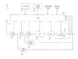
- FIG. 1is a schematic representation of a receiver architecture for a receiver which operates in accordance with the IEEE802.11 (WiFi) standard.
- FIG. 1an architecture for a receiver that operates in accordance with the IEEE 802.11 standard is shown generally at 10 .
- the receiver architecture 10is shown in FIG. 1 as being made up of functional blocks representing processing operations performed on a received signal, but these do not necessarily correspond directly to physical units that may appear within a practical implementation of a receiver. Additionally, FIG. 1 shows only those functional blocks that are necessary for an understanding of the principles of the present invention, whereas a practical implementation of a receiver may include additional functional blocks.
- the receiver 10 illustrated in FIG. 1is for receiving signals transmitted in accordance with the IEEE802.11 standard.
- the receivermay be configured to receive signals transmitted under the IEEE 802.11b standard, and the IEEE 802.11g standard, which uses an orthogonal frequency division multiplexing (OFDM) modulation scheme.
- OFDMorthogonal frequency division multiplexing
- the principles employed in the receiver 10are equally applicable to other receiver that have high dynamic range, packetized (i.e. non-continuous) operation, variable data rate and potentially bursted interferers or blockers.
- the receiver 10includes an antenna 12 for receiving signals transmitted over a radio channel.
- a signal received by the antenna 12is passed to a low noise amplifier (LNA) 14 , which amplifies the received signal before outputting an amplified version of the received signal to a mixer 16 .
- LNAlow noise amplifier
- the mixer 16mixes the amplified version of the received signal with a signal generated by a local oscillator (not shown), to downconvert the signal received by the antenna 12 to baseband for subsequent processing in the receiver 10 .
- VGAvariable gain amplifier
- the amplified signal output by the VGA 18is input to an analogue low pass filter (LPF) 20 , which filters the amplified signal to attenuate signal components outside the frequency band of interest.
- LPFanalogue low pass filter
- the filtered signal output by the LPF 20is input to an analogue to digital converter (ADC) 22 , which converts the analogue signal received by the antenna 12 and subsequently processed by the LNA 14 , mixer 16 , VGA 18 and LPF 20 into a digital signal which is decimated by a further low pass filter 24 which outputs a decimated digital signal for use in downstream processing operations such as demodulation and decoding to retrieve transmitted data from the received signal.
- ADCanalogue to digital converter
- the LNA 14 , mixer 16 , VGA 18 , LPF 20 , ADC 22 and LPF 24are all variable gain elements of the receiver 10 , and the gain of these elements is controlled by an automatic gain control 26 , which receives signals indicative of the received signal level at various points in the receiver and issues control signals to adjust the gain of one or more of the LNA 14 , mixer 16 , VGA 18 , LPF 20 , ADC 22 and LPF 24 in accordance with predefined target signal levels and signal to noise ratio (SNR) levels, as will be described below.
- SNRsignal to noise ratio
- An input of an ADC 28is connected to the output of the LNA 14 , and converts the analogue wideband signal output by the LNA 14 into a digital signal, which is output by the ADC 28 to an input of the ACG 26 , which uses this digital signal as a wideband received signal strength indicator (RSSI), that is to say an indication of the signal strength of the wideband signal received by the antenna 12 and amplified by the LNA 14 .
- RSSIwideband received signal strength indicator
- An input of a further ADC 30is connected to the output of the mixer 16 .
- the further ADC 30converts the analogue baseband signal output by the mixer into a digital signal, which is output by the ADC 30 to an input of the AGC 26 .
- the AGC 26uses this digital signal as an analogue RSSI, that is to say an indication of the signal strength of the baseband signal output by the mixer 16 .
- the AGC 26receives further digital signals from the output of the ADC 22 and the LPF 24 at its inputs, which provide a digital indication of the strength of the signals output by the ADC 22 and the LPF 24 respectively.
- the digital signals received from the ADC 22 , LPF 24 and ADCs 28 and 30are used by the AGC 26 to determine the gain settings to be applied to the variable gain elements 14 , 16 , 18 , 20 , 22 , 24 of the receiver 10 .
- the AGC 26is configured with predefined target signal levels, which it compares to the signal level indications received from the ADC 22 , LPF 24 and ADCs 28 and 30 to determine the gain settings to be applied to the variable gain elements 14 , 16 , 18 , 20 , 22 , 24 of the receiver 10 , as will be described in more detail below.
- the AGCis also configured with predefined target signal to noise ratio (SNR) levels.
- SNRtarget signal to noise ratio
- the AGC 26is configured with target SNR levels for two possible modes of operation of the receiver 10 , the first mode for receiving signals transmitted in accordance with the IEEE 802.11b standard, and the second mode for receiving IEEE 802.11 signals transmitted using an OFDM modulation scheme.
- the receiver 10includes a first synchroniser 32 , for detecting frames of a received signal that was transmitted in accordance with the IEEE 802.11b standard, and a second synchroniser 34 , for detecting frames of a received signal that was transmitted under an IEEE 802.11 standard using an OFDM modulation scheme.
- the first synchroniser 32 and the second synchroniser 34each have an output that is connected to an input of the AGC 26 , such that the AGC 26 is able to detect when a frame of an IEEE 802.11b signal or an IEEE 802.11 OFDM signal is received.
- the AGC 26has two modes of operation. The first is a continuous mode, in which the signal levels determined by the AGC 26 (referred to below as the “measured signal levels”) based on the digital signals received from the ADC 22 , LPF 24 and ADCs 28 and 30 are compared to the predefined target signal levels by the AGC 26 . If the measured signal levels do not meet the target signal levels, the ADC 26 issues command signals to one or more of the variable gain elements 14 , 16 , 18 , 20 , 22 , 24 of the receiver 10 to increase or reduce their gains to cause the measured signal levels to meet (or at least to come closer to) the predefined target signal levels.
- the ADC 26issues command signals to one or more of the variable gain elements 14 , 16 , 18 , 20 , 22 , 24 of the receiver 10 to increase or reduce their gains to cause the measured signal levels to meet (or at least to come closer to) the predefined target signal levels.
- the AGC 26includes one or more look-up tables which store gain values for each of the variable gain elements 14 , 16 , 18 , 20 , 22 , 24 against indices.
- the AGC 26may include a look-up table of gain values for the LNA 14 , indexed in order of increasing gain (i.e. the gain value stored against index 1 in the look-up table is lower than the gain value stored against index 2 ), and a separate look-up table of gain values for the VGA 18 , LPF 20 and ADC 22 indexed in order of increasing gain.
- the AGC 26stores the index of the gain value that is currently being used by each of variable gain elements 14 . If the measured signal level at a particular element of the receiver 10 does not meet the predefined target for that element, e.g. if the measured signal level at the output of the LNA 14 , as represented by the output of the ADC 28 does not meet the predefined target signal level for the output of the LNA 14 , the AGC 26 adjusts the index for that element, retrieves the gain value associated with the new index from the look-up table, and issues a command to the element to cause it to adjust its gain to the gain value retrieved from the look-up table.
- the AGC 26increases the index for the LNA 14 and retrieves the gain value associated with the increased index from the look-up table.
- the AGC 26issues a command to the LNA 14 to cause the gain of the LNA 14 to be increased to the gain value retrieved from the look-up table based on the increased index.
- the AGC 26reduces the index for the LNA 14 and retrieves the gain value associated with the reduced index from the look-up table.
- the AGC 26issues a command to the LNA 14 to cause the gain of the LNA 14 to be reduced to the gain value retrieved from the look-up table based on the reduced index.
- the AGC 26When one of the first or second synchronisers 32 , 34 detects a frame, the AGC 26 enters a locked state, in which the gains of the variable gain elements 14 , 16 , 18 , 20 , 22 , 24 of the receiver 10 are not changed. However, before the AGC enters this locked state, it performs certain actions to implement a signal to noise ratio margin by adjusting the gains of one or more of the variable gain elements 14 , 16 , 18 , 20 , 22 , 24 of the receiver 10 , to prevent saturation of the variable gain elements 14 , 16 , 18 , 20 , 22 , 24 of the receiver 10 in the event that interference is received during reception of a frame by the receiver 10 .
- Thisovercomes the problem in existing receivers that the beginning of a data frame is correctly received (i.e. the transmitted data contained in the received data frame can be correctly demodulated/decoded), but the end of the data frame is not.
- the AGC 26performs a fine measurement of the signal levels at the various different points in the receiver 10 , by evaluating the signals received at its inputs from the ADC 22 , the LPF 24 and the ADCs 28 , 30 .
- the first and second synchronisers 32 , 34are configured to detect a periodic preamble contained in a received signal to identify the received signal as an IEEE 802.11 signal. As the preamble is periodic, the total energy in the preamble is constant over one period.
- the AGC 26measures the signal levels received at its inputs over one or more periods, and selects gain values for each of the variable gain elements 14 , 16 , 18 , 20 , 22 , 24 to implement a more even distribution of the total gain of the receiver 10 over the variable gain elements 14 , 16 , 18 , 20 , 22 , 24 .
- the gain of the LNA 14is adjusted, if the difference between the measured signal level and the target signal level is higher than the gain step provided by the LNA 14 . Then the gain of the mixer 16 is adjusted based on the same criterion, taking into account the selected adjustment to the gain of the LNA 14 (since gain changes propagate through the receiver architecture).
- an increase in the gain of the LNA 14will affect the signal level at the mixer 16 , such that if, based on the measured signal strength at the AGC 26 , the AGC 26 determines that a gain step of +6 dBm is required at both the LNA 14 and the mixer 16 , only the gain of the LNA 14 is increased to meet this requirement, as in doing so the requirement for a gain step at the mixer 16 will also be met, due to the propagation of the gain change of the LNA 14 through the receiver architecture.
- the AGC 26issues commands to the variable gain elements 14 , 16 , 18 , 20 , 22 , 24 to set their gains to the new values determined by the AGC 26 , and the AGC 26 stores the indices of the gain values for each of the variable gain elements 14 , 16 , 18 , 20 , 22 , 24 .
- the new gain valuesare referred to below as the “gain values at lock”
- the AGC 26estimates a signal to noise ratio margin between the predefined SNR target and an estimated SNR of the received signal, as will be described below.
- the signal level of the received signalis estimated based on the gain values at lock used by each of the variable gain elements 14 , 16 , 18 , 20 , 22 , 24 of the receiver 10 and the signal strength indicator received by the AGC 26 from the output of the decimation LPF 24 .
- the gain values at lock used by each of the variable gain elements 14 , 16 , 18 , 20 , 22 , 24are retrieved from the look-up table(s) using the indices stored by the AGC 26 , and these gain values are multiplied together to generate an estimate of the total gain of the receiver 10 .
- the signal strength indicator from the output of the decimation LPF 24is divided by this total gain estimate, to generate an estimate of the signal level of the signal received at the antenna 12 .
- a noise figure for the signal output by the decimation filter 24is used in the estimation of the SNR of the received signal.
- This noise figuredepends mainly on the gain values at lock of the LNA 14 and the mixer 16 , and so the gain values at lock of the LNA 14 and the mixer 16 are retrieved by the AGC 26 from the look-up table(s) using the relevant indices. Based on these gain values, the AGC 26 retrieves from a look-up table an estimate of the noise figure at the time that the AGC 26 entered its locked mode.
- an estimate of the signal to noise ratio of the received signalis calculated by the AGC 26 based on the estimated signal level, noise figure and constants that depend on the absolute gain of the receiver 10 and signal bandwidth, as described below.
- Thermal noiseis a constant for a given receiver configuration, and this constant depends on the bandwidth of the signal following digital decimation by the decimation filter 24 . Thermal noise is also proportional to absolute temperature (in Kelvin), and so it is possible for the AGC 26 to compensate for temperature, variations in determining the SNR.
- the constant in this equationis used to compensate for the difference in units between the RSSI and the gain value.
- the calculated SNR estimateis compared by the AGC 26 to the predefined SNR target for the relevant reception mode (802.11b or 802.11 OFDM) of the receiver to calculate an SNR margin. To do this the AGC 26 subtracts the SNR target from the SNR estimate, thereby generating the SNR margin.
- the SNR marginmust be greater than zero.
- the gain of the LNA 14 and of the mixer 16should be as low as possible. The SNR margin is used to tune the trade-off between SNR level and accommodation of potential interference.
- the AGC 26performs a search to identify a gain index that corresponds to a reduced gain value for the LNA 14 and/or the mixer 16 that will result in a reduced SNR for the receiver and thus a reduced SNR margin, whilst retaining a positive SNR margin.
- a gain commandis sent by the AGC 26 to the LNA 14 and/or the mixer 16 to set the gain to the corresponding gain value.
- the amount of gain reduction applied to the LNA 14 and mixer 16is compensated by an increase in the gain of the subsequent variable gain elements 18 , 20 , 22 , 24 .
- the design of the receiver 10is such that it is always possible to compensate such a gain reduction in the RF section (the LNA 14 and mixer 16 ) with a gain increase in the baseband section (the VGA 18 , LPF 20 , ADC 22 and LPF 24 ).
- This reduction in the gain value of the LNA 14 and/or the mixer 16has the effect of protecting the variable gain components 14 , 16 , 18 , 20 , 22 , 24 from saturation in the event that an interfering signal commences after the AGC has entered its locked mode, since the reduction in the gain of the LNA 14 and/or of the mixer 16 reduces the effect of the increased signal level at the antenna 12 resulting from the presence of the interfering signal, such that the variable gain components 14 , 16 , 18 , 20 , 22 , 24 are able to accommodate the increased signal level at their inputs without saturating.
- the AGC 26may be configured to perform a search to identify a gain index that corresponds to a reduced gain value for the LNA 14 before performing such a search for the mixer 16 , such that the gain of the LNA 14 is adjusted before any adjustment is made to the gain of the mixer 16 .
- the use of the SNR of the receiver 10 as a metric for the AGC 26 in this wayreduces the susceptibility of the receiver 10 to interference that commences part way through reception of a frame of an IEEE 802.11 signal, whilst ensuring that the SNR of the receiver meets the predefined target SNR, or is as high as possible when signal level is low.
Landscapes
- Circuits Of Receivers In General (AREA)
- Control Of Amplification And Gain Control (AREA)
- Noise Elimination (AREA)
Abstract
Description
SNR=signal in−thermal noise−noise figure.
signal in=RSSI−gain+constant.
SNR=RSSI−gain+constant−thermal noise−noise figure.
Claims (9)
Priority Applications (3)
| Application Number | Priority Date | Filing Date | Title |
|---|---|---|---|
| US13/454,005US8675789B2 (en) | 2012-04-23 | 2012-04-23 | Receiver with variable gain elements and automatic gain control to maintain a positive signal to noise ratio margin |
| GB1301811.4AGB2501577A (en) | 2012-04-23 | 2013-02-01 | Receiver AGC system with improved accommodation of interference |
| DE102013005051.0ADE102013005051B4 (en) | 2012-04-23 | 2013-03-22 | Receiver with automatic gain control |
Applications Claiming Priority (1)
| Application Number | Priority Date | Filing Date | Title |
|---|---|---|---|
| US13/454,005US8675789B2 (en) | 2012-04-23 | 2012-04-23 | Receiver with variable gain elements and automatic gain control to maintain a positive signal to noise ratio margin |
Publications (2)
| Publication Number | Publication Date |
|---|---|
| US20130279556A1 US20130279556A1 (en) | 2013-10-24 |
| US8675789B2true US8675789B2 (en) | 2014-03-18 |
Family
ID=47988556
Family Applications (1)
| Application Number | Title | Priority Date | Filing Date |
|---|---|---|---|
| US13/454,005Expired - Fee RelatedUS8675789B2 (en) | 2012-04-23 | 2012-04-23 | Receiver with variable gain elements and automatic gain control to maintain a positive signal to noise ratio margin |
Country Status (3)
| Country | Link |
|---|---|
| US (1) | US8675789B2 (en) |
| DE (1) | DE102013005051B4 (en) |
| GB (1) | GB2501577A (en) |
Cited By (3)
| Publication number | Priority date | Publication date | Assignee | Title |
|---|---|---|---|---|
| US20140018027A1 (en)* | 2011-03-30 | 2014-01-16 | Telefonaktiebolaget L M Ericsson (Publ) | Technique for automatic gain control |
| US10581474B1 (en) | 2018-11-21 | 2020-03-03 | Nxp B.V. | Wireless receivers and related methods with random interferer immunity |
| US10734961B2 (en) | 2017-10-26 | 2020-08-04 | Nxp B.V. | Automatic gain controller |
Families Citing this family (26)
| Publication number | Priority date | Publication date | Assignee | Title |
|---|---|---|---|---|
| US10257729B2 (en) | 2013-03-15 | 2019-04-09 | DGS Global Systems, Inc. | Systems, methods, and devices having databases for electronic spectrum management |
| US12356206B2 (en) | 2013-03-15 | 2025-07-08 | Digital Global Systems, Inc. | Systems and methods for automated financial settlements for dynamic spectrum sharing |
| US10219163B2 (en) | 2013-03-15 | 2019-02-26 | DGS Global Systems, Inc. | Systems, methods, and devices for electronic spectrum management |
| US10257728B2 (en) | 2013-03-15 | 2019-04-09 | DGS Global Systems, Inc. | Systems, methods, and devices for electronic spectrum management |
| US11646918B2 (en) | 2013-03-15 | 2023-05-09 | Digital Global Systems, Inc. | Systems, methods, and devices for electronic spectrum management for identifying open space |
| US12256233B2 (en) | 2013-03-15 | 2025-03-18 | Digital Global Systems, Inc. | Systems and methods for automated financial settlements for dynamic spectrum sharing |
| US10299149B2 (en) | 2013-03-15 | 2019-05-21 | DGS Global Systems, Inc. | Systems, methods, and devices for electronic spectrum management |
| US10231206B2 (en) | 2013-03-15 | 2019-03-12 | DGS Global Systems, Inc. | Systems, methods, and devices for electronic spectrum management for identifying signal-emitting devices |
| US9078162B2 (en)* | 2013-03-15 | 2015-07-07 | DGS Global Systems, Inc. | Systems, methods, and devices for electronic spectrum management |
| US10237770B2 (en) | 2013-03-15 | 2019-03-19 | DGS Global Systems, Inc. | Systems, methods, and devices having databases and automated reports for electronic spectrum management |
| US10271233B2 (en) | 2013-03-15 | 2019-04-23 | DGS Global Systems, Inc. | Systems, methods, and devices for automatic signal detection with temporal feature extraction within a spectrum |
| US10257727B2 (en) | 2013-03-15 | 2019-04-09 | DGS Global Systems, Inc. | Systems methods, and devices having databases and automated reports for electronic spectrum management |
| US9124234B1 (en)* | 2014-04-11 | 2015-09-01 | Entropic Communications, LLC. | Method and apparatus for adaptive automatic gain control |
| GB2533300B (en)* | 2014-12-15 | 2017-03-22 | Nordic Semiconductor Asa | Packet-based radio receiver with automatic gain control |
| US10459020B2 (en) | 2017-01-23 | 2019-10-29 | DGS Global Systems, Inc. | Systems, methods, and devices for automatic signal detection based on power distribution by frequency over time within a spectrum |
| US10498951B2 (en) | 2017-01-23 | 2019-12-03 | Digital Global Systems, Inc. | Systems, methods, and devices for unmanned vehicle detection |
| US12205477B2 (en) | 2017-01-23 | 2025-01-21 | Digital Global Systems, Inc. | Unmanned vehicle recognition and threat management |
| US10529241B2 (en) | 2017-01-23 | 2020-01-07 | Digital Global Systems, Inc. | Unmanned vehicle recognition and threat management |
| US10700794B2 (en) | 2017-01-23 | 2020-06-30 | Digital Global Systems, Inc. | Systems, methods, and devices for automatic signal detection based on power distribution by frequency over time within an electromagnetic spectrum |
| US12183213B1 (en) | 2017-01-23 | 2024-12-31 | Digital Global Systems, Inc. | Unmanned vehicle recognition and threat management |
| JP6684740B2 (en)* | 2017-03-07 | 2020-04-22 | 株式会社東芝 | Wireless receiver |
| CN108900171A (en)* | 2018-07-23 | 2018-11-27 | 上海亮牛半导体科技有限公司 | A kind of AGC device and method being adapted to zero intermediate frequency radio-frequency transmitter |
| US10943461B2 (en) | 2018-08-24 | 2021-03-09 | Digital Global Systems, Inc. | Systems, methods, and devices for automatic signal detection based on power distribution by frequency over time |
| CN109831231B (en)* | 2019-04-24 | 2019-07-12 | 翱捷科技(上海)有限公司 | A kind of bluetooth baseband receives system and its implementation |
| CN112312534B (en)* | 2020-10-30 | 2022-08-16 | 展讯通信(天津)有限公司 | Method and system for adjusting receiving link gain and intelligent terminal |
| CN116569490B (en)* | 2023-03-06 | 2025-07-29 | 香港应用科技研究院有限公司 | Automatic Gain Control (AGC) for on-off keying (OOK) receivers |
Citations (9)
| Publication number | Priority date | Publication date | Assignee | Title |
|---|---|---|---|---|
| US4876737A (en)* | 1986-11-26 | 1989-10-24 | Microdyne Corporation | Satellite data transmission and receiving station |
| US20030162518A1 (en) | 2002-02-22 | 2003-08-28 | Baldwin Keith R. | Rapid acquisition and tracking system for a wireless packet-based communication device |
| US20060034401A1 (en)* | 2004-08-10 | 2006-02-16 | Samsung Electronics Co., Ltd. | Apparatus and method for controlling a digital automatic gain controller in an orthogonal frequency division multiple access communication system |
| WO2006099530A2 (en) | 2005-03-11 | 2006-09-21 | Qualcomm Incorporated | Automatic gain control for a wireless receiver |
| US20070076783A1 (en) | 2005-10-03 | 2007-04-05 | Harris Corporation | Frequency selective automatic gain control with dual non-symmetric attack and release times and interference detection feature |
| US20080014894A1 (en)* | 2004-05-13 | 2008-01-17 | Sirific Wireless Corporation | Method And System For Spurious Signal Control In Receivers |
| US20090207767A1 (en)* | 2004-08-31 | 2009-08-20 | Nxp B.V. | Cycled receiver for mobile wireless devices |
| US20110149773A1 (en) | 2009-12-17 | 2011-06-23 | Electronics And Telecommunications Research Institute | Apparatus and method for receiving data in wireless communication system |
| US20120057621A1 (en)* | 2010-01-26 | 2012-03-08 | Maxlinear, Inc. | Diversity Receiver |
- 2012
- 2012-04-23USUS13/454,005patent/US8675789B2/ennot_activeExpired - Fee Related
- 2013
- 2013-02-01GBGB1301811.4Apatent/GB2501577A/ennot_activeWithdrawn
- 2013-03-22DEDE102013005051.0Apatent/DE102013005051B4/ennot_activeExpired - Fee Related
Patent Citations (9)
| Publication number | Priority date | Publication date | Assignee | Title |
|---|---|---|---|---|
| US4876737A (en)* | 1986-11-26 | 1989-10-24 | Microdyne Corporation | Satellite data transmission and receiving station |
| US20030162518A1 (en) | 2002-02-22 | 2003-08-28 | Baldwin Keith R. | Rapid acquisition and tracking system for a wireless packet-based communication device |
| US20080014894A1 (en)* | 2004-05-13 | 2008-01-17 | Sirific Wireless Corporation | Method And System For Spurious Signal Control In Receivers |
| US20060034401A1 (en)* | 2004-08-10 | 2006-02-16 | Samsung Electronics Co., Ltd. | Apparatus and method for controlling a digital automatic gain controller in an orthogonal frequency division multiple access communication system |
| US20090207767A1 (en)* | 2004-08-31 | 2009-08-20 | Nxp B.V. | Cycled receiver for mobile wireless devices |
| WO2006099530A2 (en) | 2005-03-11 | 2006-09-21 | Qualcomm Incorporated | Automatic gain control for a wireless receiver |
| US20070076783A1 (en) | 2005-10-03 | 2007-04-05 | Harris Corporation | Frequency selective automatic gain control with dual non-symmetric attack and release times and interference detection feature |
| US20110149773A1 (en) | 2009-12-17 | 2011-06-23 | Electronics And Telecommunications Research Institute | Apparatus and method for receiving data in wireless communication system |
| US20120057621A1 (en)* | 2010-01-26 | 2012-03-08 | Maxlinear, Inc. | Diversity Receiver |
Non-Patent Citations (1)
| Title |
|---|
| Search Report for GB Application 1301811.4 dated May 24, 2013. |
Cited By (4)
| Publication number | Priority date | Publication date | Assignee | Title |
|---|---|---|---|---|
| US20140018027A1 (en)* | 2011-03-30 | 2014-01-16 | Telefonaktiebolaget L M Ericsson (Publ) | Technique for automatic gain control |
| US9143177B2 (en)* | 2011-03-30 | 2015-09-22 | Telefonaktiebolaget L M Ericsson (Publ) | Technique for automatic gain control |
| US10734961B2 (en) | 2017-10-26 | 2020-08-04 | Nxp B.V. | Automatic gain controller |
| US10581474B1 (en) | 2018-11-21 | 2020-03-03 | Nxp B.V. | Wireless receivers and related methods with random interferer immunity |
Also Published As
| Publication number | Publication date |
|---|---|
| DE102013005051B4 (en) | 2018-02-22 |
| US20130279556A1 (en) | 2013-10-24 |
| GB201301811D0 (en) | 2013-03-20 |
| DE102013005051A1 (en) | 2013-10-24 |
| GB2501577A (en) | 2013-10-30 |
Similar Documents
| Publication | Publication Date | Title |
|---|---|---|
| US8675789B2 (en) | Receiver with variable gain elements and automatic gain control to maintain a positive signal to noise ratio margin | |
| US7979049B2 (en) | Automatic filter control | |
| US8494469B2 (en) | Detection and mitigation of interference in a multimode receiver using variable bandwidth filter | |
| US7620380B2 (en) | Adjustable automatic gain control | |
| US7580690B2 (en) | High-frequency receiver having a gain switch controller | |
| US8818313B2 (en) | Method and apparatus for auto gain control in radio receiver | |
| WO2009100099A2 (en) | System and method for station detection and seek in a radio receiver | |
| EP3113370B1 (en) | Preemptive automatic gain control (agc) for interference mitigation | |
| US20130028357A1 (en) | Detection and mitigation of interference in a receiver | |
| US8737545B2 (en) | Receiver chain gain selection | |
| US20060079193A1 (en) | Radio receiver and gain control method | |
| US20110021168A1 (en) | Method and apparatus for receiver with dual mode automatic gain control (agc) | |
| US9325359B2 (en) | Radiofrequency signal setting reaching a condition of jamming or clipping | |
| US20120252389A1 (en) | Efficient scheme for automatic gain control in communication systems | |
| JP2008219364A (en) | Microwave relay receiver | |
| CN107210768B (en) | Carrier-to-noise ratio detection circuit and receiver circuit | |
| KR20180094319A (en) | Apparatus and Method For Providing Automatic Gain Control | |
| KR101332051B1 (en) | Signal processing apparatus, system and method for automatic gain control using the same | |
| KR101509498B1 (en) | Two - step alalog digital mixed automatic gain controller and method thereof | |
| JP2010226153A (en) | Line status estimator | |
| KR100690438B1 (en) | Automatic gain control method with variable gain adjustment interval and device | |
| EP1499014A1 (en) | A method for automatic gain control, for instance in a telecommunication system, device and computer program therefor | |
| KR100651493B1 (en) | Gain Control Device and Method in Receiver | |
| US8375769B2 (en) | Method for SINR measurement with controlling residual gain in HSPA/HSDPA system and apparatus thereof | |
| KR20130067541A (en) | Method for receiving radio signal in wireless communication system and apparatus for the same |
Legal Events
| Date | Code | Title | Description |
|---|---|---|---|
| AS | Assignment | Owner name:CAMBRIDGE SILICON RADIO LIMITED, UNITED KINGDOM Free format text:ASSIGNMENT OF ASSIGNORS INTEREST;ASSIGNOR:SELLER, OLIVER;REEL/FRAME:028092/0648 Effective date:20120416 | |
| AS | Assignment | Owner name:CAMBRIDGE SILICON RADIO LIMITED, UNITED KINGDOM Free format text:CONFIRMATORY ASSIGNMENT TO CORRECT SPELLING OF INVENTOR'S NAME ON NOTICE OF RECORDATION FOR ASSIGNMENT RECORDED AT REEL/FRAME 028092/0648 ON APRIL 23, 2012;ASSIGNOR:SELLER, OLIVIER;REEL/FRAME:028344/0428 Effective date:20120416 | |
| FEPP | Fee payment procedure | Free format text:PAYOR NUMBER ASSIGNED (ORIGINAL EVENT CODE: ASPN); ENTITY STATUS OF PATENT OWNER: LARGE ENTITY | |
| STCF | Information on status: patent grant | Free format text:PATENTED CASE | |
| AS | Assignment | Owner name:QUALCOMM TECHNOLOGIES INTERNATIONAL, LTD., UNITED Free format text:CHANGE OF NAME;ASSIGNOR:CAMBRIDGE SILICON RADIO LIMITED;REEL/FRAME:036663/0211 Effective date:20150813 | |
| FEPP | Fee payment procedure | Free format text:PAYOR NUMBER ASSIGNED (ORIGINAL EVENT CODE: ASPN); ENTITY STATUS OF PATENT OWNER: LARGE ENTITY Free format text:PAYER NUMBER DE-ASSIGNED (ORIGINAL EVENT CODE: RMPN); ENTITY STATUS OF PATENT OWNER: LARGE ENTITY | |
| MAFP | Maintenance fee payment | Free format text:PAYMENT OF MAINTENANCE FEE, 4TH YEAR, LARGE ENTITY (ORIGINAL EVENT CODE: M1551) Year of fee payment:4 | |
| FEPP | Fee payment procedure | Free format text:MAINTENANCE FEE REMINDER MAILED (ORIGINAL EVENT CODE: REM.); ENTITY STATUS OF PATENT OWNER: LARGE ENTITY | |
| LAPS | Lapse for failure to pay maintenance fees | Free format text:PATENT EXPIRED FOR FAILURE TO PAY MAINTENANCE FEES (ORIGINAL EVENT CODE: EXP.); ENTITY STATUS OF PATENT OWNER: LARGE ENTITY | |
| STCH | Information on status: patent discontinuation | Free format text:PATENT EXPIRED DUE TO NONPAYMENT OF MAINTENANCE FEES UNDER 37 CFR 1.362 | |
| FP | Lapsed due to failure to pay maintenance fee | Effective date:20220318 |