US8675711B1 - System and methods for dynamic spread spectrum usage - Google Patents
System and methods for dynamic spread spectrum usageDownload PDFInfo
- Publication number
- US8675711B1 US8675711B1US12/890,578US89057810AUS8675711B1US 8675711 B1US8675711 B1US 8675711B1US 89057810 AUS89057810 AUS 89057810AUS 8675711 B1US8675711 B1US 8675711B1
- Authority
- US
- United States
- Prior art keywords
- bits
- signal
- bandwidth
- transmitter
- intervals
- Prior art date
- Legal status (The legal status is an assumption and is not a legal conclusion. Google has not performed a legal analysis and makes no representation as to the accuracy of the status listed.)
- Active, expires
Links
Images


Classifications
- H—ELECTRICITY
- H04—ELECTRIC COMMUNICATION TECHNIQUE
- H04B—TRANSMISSION
- H04B1/00—Details of transmission systems, not covered by a single one of groups H04B3/00 - H04B13/00; Details of transmission systems not characterised by the medium used for transmission
- H04B1/69—Spread spectrum techniques
- H04B1/707—Spread spectrum techniques using direct sequence modulation
- H—ELECTRICITY
- H04—ELECTRIC COMMUNICATION TECHNIQUE
- H04B—TRANSMISSION
- H04B7/00—Radio transmission systems, i.e. using radiation field
- H04B7/14—Relay systems
- H04B7/15—Active relay systems
- H04B7/185—Space-based or airborne stations; Stations for satellite systems
- H04B7/1851—Systems using a satellite or space-based relay
- H04B7/18517—Transmission equipment in earth stations
Definitions
- the disclosed embodimentsrelate generally to communications. More particularly, the disclosed embodiments relate to transmission of spread spectrum signals.
- bandwidth ownerse.g., bent-pipe satellite operators
- portions of bandwidth that are unutilized or underutilizedThose same bandwidth owners have portions of bandwidth that are currently utilized, but which can also support a “below the noise” low data rate system as an added functionality.
- the bandwidth in questionmay be highly fragmented (e.g., separated into relatively small portions of spectrum), may change with time or geographic location, and may have different background noise levels and signal transmission requirements.
- a transmitter for transmitting a signal to a receiver using spread spectrum signalsis configured to: generate a respective signal; and separate the respective signal into multiple predefined portions. Each predefined portion is below a noise floor.
- the transmitteris further configured to transmit at least a plurality of the predefined portions of the respective signal at discrete bandwidth intervals in accordance with a spread spectrum signal splitting technique.
- the discrete bandwidth intervalsare portions of spectrum that are available for transmission.
- a receiver for reconstructing a signal from a transmitter from a plurality of spread spectrum signalsis configured to: receive multiple predefined portions of a respective signal at discrete bandwidth intervals. Each predefined portion is below a noise floor. The receiver is further configured to reconstruct the respective signal using at least a plurality of the predefined portions in accordance with a spread spectrum signal splitting technique.
- the transmitter for transmitting signalsuses a spread spectrum signal splitting technique including: generating a respective signal and separating the respective signal into multiple of bits for transmission at one of the discrete bandwidth intervals that are available for transmission.
- a plurality of the bitshave a predefined width that corresponds to a minimum amount of spectrum required to transmit the bit in a predefined duration.
- the spread spectrum signal splitting techniquefurther includes transmitting the plurality of bits in the discrete bandwidth intervals such that the transmission is below the noise floor.
- the transmitter for transmitting signalsuses a spread spectrum signal splitting technique including: generating a respective signal and separating the respective signal into multiple bits for transmission at the discrete bandwidth intervals that are available for transmission.
- a plurality of the bitseach have a predefined width that is determined based on a width of one of the discrete bandwidth intervals.
- the spread spectrum signal splitting techniquefurther includes transmitting the plurality of bits in the discrete bandwidth intervals. The plurality of bits are each transmitted for a duration that is determined based on a predefined width of the bit, such that the transmission is below the noise floor.
- the transmitter for transmitting signalsuses a spread spectrum signal splitting technique including: generating a respective signal and in a frequency domain, dividing the respective signal into a plurality of signal pieces.
- a plurality of the signal pieceseach have a piece width less than or equal to a respective spectrum width of a corresponding discrete bandwidth interval that is available for transmission.
- the spread spectrum signal techniquefurther includes transmitting each of the plurality of the signal pieces at a corresponding discrete bandwidth interval such that the transmission is below the noise floor.
- the disclosed transmitters, receivers, and spread spectrum signal splitting techniquesprovide improvements over conventional approaches by improving the utilization of available bandwidth and reducing the cost of transmitters.
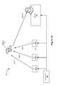
- FIG. 1Ais an exemplary block diagram of a communication system in accordance with some embodiments.
- FIG. 1Bis an exemplary transmitter in accordance with some embodiments.
- FIG. 1Cis an exemplary central receiver in accordance with some embodiments.
- FIG. 2Ais timing diagram illustrating a spread spectrum signal in accordance with some embodiments.
- FIG. 2Bis a timing diagram illustrating available spectrum in accordance with some embodiments.
- FIG. 2Cis a block diagram of an outbound data stream in accordance with some embodiments
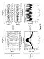
- FIGS. 3A-Hare timing diagrams of transmission signals in accordance with some embodiments.
- FIG. 4is a block diagram illustrating a transmitter in accordance with some embodiments.
- FIG. 5is a block diagram illustrating a receiver in accordance with some embodiments.
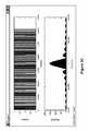
- FIG. 6is a timing diagram of received signals in accordance with some embodiments.
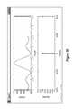
- FIG. 7is timing diagram of received signals in accordance with some embodiments.
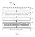
- FIG. 8is a flow chart of a method for transmitting a spread spectrum signal in accordance with some embodiments.
- FIG. 9is a flow chart of a method for transmitting a spread spectrum signal in accordance with some embodiments.
- FIG. 10is a flow chart of a method for transmitting a spread spectrum signal in accordance with some embodiments.
- many transmitters 102e.g., T1, T2 . . . TN
- a central receiver 104e.g., receiver
- the small portions of dataare transmitted from one of the transmitters 102 to a satellite 105 via satellite uplink and transmitted by the satellite to the receiver 104 via a satellite downlink, as illustrated in FIG. 1A .
- the receiveris able to distinguish between the many transmitter by code phase.
- a central unit 106provides the transmitters 102 with information enabling a spread spectrum signal to be separated into multiple predefined portions and provides the receiver 104 with information enabling the spread spectrum signal to be reconstructed. In some embodiments, the central unit 106 also synchronizes timing of the transmitters 102 and the receiver(s) 104 .
- FIG. 1BAn exemplary illustration of a transmitter is shown in FIG. 1B .
- FIG. 4A block diagram illustrating a transmitter in accordance with some embodiments is illustrated in FIG. 4 .
- the transmitters 102are designed to use as few resources as possible in order to maintain minimal power, minimal size, and maximal lifetime from small battery pack.
- the transmitter's simplicityis compensated for at the central receiver.
- An exemplary illustration of a central receiveris shown in FIG. 1C .
- the central receiverdeals with overlapping messages, transmitter frequency variation, and error correction.
- a single 8-channel receiversupports over 1.5 million remote devices, each transmitting twice per day.
- the 1.5 million remote device figureis derived from 1.05 s transmission (128 b at 122 bps), 8 geographically independent channels with 50-overlapping capacity; 18.44% Aloha optimal occupation, 2 packet slots occupied per packet transmission (due to repeats), 2 transmissions per day. This is a soft limit; peak capacity is greater by up to a factor of 5.
- all communicationsuse Direct-Sequence Spread Spectrum (DSSS) in order to transmit signals below the noise floor (e.g., the transmitted signal is substantially indistinguishable from white noise for receivers other than the receivers 104 that are coordinated with the transmitters 102 ).
- DSSSDirect-Sequence Spread Spectrum
- the modulated signalis spread across a bandwidth that is substantially larger than the bandwidth of the information signal, and has the apparent effect of increasing the noise floor of receivers that receive this signal. Applying the same pseudo-random sequence to the modulated signal allows the information signal to be detected within this apparent noise.
- an original signal to be transmitted by a transmitteris transformed into a modulated signal (e.g., a spread spectrum signal) by multiplying the original signal by a pseudo-random sequence.
- a modulated signale.g., a spread spectrum signal
- the modulated signalis spread across a bandwidth that is substantially larger than the bandwidth of the information signal, and has the apparent effect of increasing the noise floor of receivers that receive this signal.
- Applying the same pseudo-random sequence to the modulated signalallows the information signal to be detected within this apparent noise by a receiver 104 .
- the numbers used in FIG. 2Aare examples. Those skilled in the art will recognize that systems exhibiting different characteristics can be used.
- the signalmay be virtually any type of signal.
- the signalindicates a geographical location of the transmitter.
- the signalmay be coordinates determined using a global positioning system (GPS) receiver or other type of location detection hardware/software.
- GPSglobal positioning system
- the signalmay include an indicator of a state of the transmitter, such as: an indication of the operational status of the indicator (e.g., fully operation, low battery, damaged circuitry, etc.), and/or an indication of a movement status of the indicator, etc.
- transmission of the spread spectrum signalraises the noise floor by ⁇ 0.1%.
- This estimation of the noise flooris based on the following assumptions: a 1023-chip code, repeated 8 times per information bit, for an effective spreading ratio of 8184:1, or 39.13 dB.
- the impact on the noise flooris ⁇ 30 dB, or 0.1%
- the average impact across the entire spread curveis ⁇ 34 dB, or 0.0398%. Consequently, in this example, transmitters will thus raise the noise floor an average of 1.99%. It should be noted that, in this embodiment, all of these ratios apply independent of the actual spreading or information bit rates.
- DSSScan accommodate up to 10 dB of fluctuation and still raise the noise floor by ⁇ 1% or can accommodate 50 overlapping transmissions while raising the noise floor an average of ⁇ 2%.
- typical non-spread spectrum signalsare 5 to 20 Db above the noise floor.
- a repeated codewill not be a single smooth curve, but a series of spectral lines.
- practical experience with these systemsshows that the behavior is as shown here, in that it is dependent wholly on the spreading ratio, and acts to other spectrum users like a smooth curve.
- Code Phase Division Multiple Access (CPDMA) techniquesallow a plurality of transmitters to use the same spread code and center frequency.
- the receiveris capable of distinguishing among overlapping transmissions because the transmitters are uncoordinated, and thus, start transmitting their spreading codes at different times. As a result, the spreading codes are offset from one another.
- the receiversearches all possible code phases and all possible transmitter frequency offsets simultaneously. This arrangement is advantageous in situations where the transmitters are desired to be as simple and power efficient as possible, while receivers are not constrained by simplicity or power consumption concerns (e.g., the computationally intensive operations are offloaded onto the receiver, so as to enable the transmitters to be simplified).
- bandwidthmay be “available” or “unavailable” for transmission at any given frequency or frequency range (e.g., a discrete bandwidth interval).
- Bandwidth ownersoften have portions of bandwidth that are unutilized or underutilized. Further, even if the bandwidth is utilized, it may also support a “below the noise” approach as an added function. All three of these cases result in “available” bandwidth (e.g., unused bandwidth, underutilized bandwidth, and below-the-noise bandwidth). In these cases, however, the bandwidth available to transmit the spread-spectrum signal may be separated into several or many relatively small portions of spectrum, may change with time or geographic location, and may have different background noise levels.
- a central data warehouse computere.g., central unit 106 identifies discrete bandwidth intervals that are available for a zone (e.g., a geographic region) and conveys signal processing information to the transmitters that enables the transmitters 102 to separate a spread spectrum signal into multiple predefined portions and transmit the spread spectrum signal via the discrete bandwidth intervals.
- the central unit 106 and the transmitters 102are connected via a wireless link. The central unit 106 ( FIG. 1A ) is informed of the discrete bandwidth interval changes or desired changes in how the discrete bandwidth intervals are used (e.g., by an operator of the system).
- the central unit 106can then create the optimal samples to shape the intended spread-spectrum signal.
- the central unit 106also informs the receiver 104 of the update and its effective time.
- the receiver 104listens to the outbound data stream of the central unit 106 at a regular interval known to both the receiver 104 and the central unit 106 .
- the data stream of the central unit 106is illustrated in FIG. 2C .
- the intervalis frequent (e.g., every 1 ⁇ 2 second).
- the intervalis relatively long (e.g., every 1 ⁇ 2 day).
- the central unit 106 and the receiver 104are connected via a wireless link.
- All of the transmitters 102receive messages from the central unit 106 to update the respective waveforms.
- the messageis a set of instructions for creating the samples and includes an absolute time to perform the switch so that all of the transmitters 102 switch at the same moment.
- the outbound data streamis also below the noise of the primary system users.
- discrete occupationAs disclosed below, several techniques (e.g., discrete occupation, tailored occupation, and spectral distribution) can be implemented in order to fit the spread-spectrum signal to the available discrete bandwidth intervals. What discrete bandwidth interval receives what portion of the spread spectrum source signal can be chosen based on the primary use of that discrete bandwidth interval. Accordingly, underused discrete bandwidth intervals, even narrow ones, can be put to good use.
- some predefined minimum amount of spectrum(e.g., 16 kHz) is used to convey only one bit of the spread spectrum signal, as described in greater detail below with reference to FIG. 8 . If 32 kHz are available, two bits are sent “side by side” in spectrum. In other words, in this approach, the waveforms used to transmit signals are not adjusted for larger discrete bandwidth intervals, rather in a larger discrete bandwidth interval, multiple waveforms are transmitted with different center frequencies. It should be noted that 16 kHz is used as the minimum amount of spectrum for discussion purposes only. One skilled in the art would recognize that the minimum amount of spectrum available could be equal to any bandwidth.
- individual portions of a data packetare sent at different center frequencies.
- a single bitis sent per center frequency.
- adjacent center frequenciesare held in a common phase to allow tighter frequency packing, while in other embodiments, adjacent center frequencies are not specifically held in common phase.
- DSSSDirect Sequence Spread Spectrum
- the receiverneeds, for example, 9 dB of signal-to-noise ratio in a bit in order to correctly decode the bit, then 9-10 log 10(8000/bitrate) is how far below the noise the spread spectrum signal will end up in dB. Assuming a bitrate of one bit per second, then the transmitted signal will be (at maximum) 30 dB below the noise floor, and thus, invisible to other users of the spectrum. In other words, the signal is sent at a lower power for a longer period of time and thus is detectable by a receiver that is looking for the signal, but is not detectable by a receiver that is not looking for the signal, because the power is below the noise floor for a typical receiver.
- CPDMAthird method of multiple-access
- MLMaximal Length
- all transmittersuse the same spreading code
- a relatively high data ratee.g. 30 MHz wide
- the transmittersare told, either at manufacture or at provisioning or at some other moment appropriate to the host system, which discrete bandwidth intervals to use, how wide they are, what spreading code(s) to use (the presumption is for each 16 kHz-wide ‘bit’ to have the same spreading code, but they can use different ones if it makes sense on the host system), and what the bit rate is.
- the transmitterwhich is presumably a digital logic device sending samples at relatively high rate (say, 70 MSps) to a Digital-to-Analog converter for transmission, can create precisely the waveform necessary to accomplish the discrete occupation distribution of bits. That is, one mass-manufactured piece of hardware can take advantage of any width, distribution, relative characteristics, below-the-noise requirements, and quantity of available sections of bandwidth. It can then change, with no more effort than the update of these parameters, to accommodate a different set of available discrete bandwidth intervals, as they become available because the transmitter moved or the host system's circumstances changed.
- any optimization or performance enhancemente.g. optimizing the sample stream the transmitters send to their DACs
- the transmitteris described further below in connection with FIG. 4 .
- Capacity enhancementsin particular can benefit from adjusting any of these parameters, with the corresponding increase in receiver hardware to receive the new variations.
- the discrete occupation approachputs, for example, 4 bits adjacent to one another in 64 kHz of space, sending its spreading code at each of four frequency centers with an available discrete bandwidth interval.
- the discrete bandwidth intervalsare used to determine the width of signals, and the duration of the signals is based on the width of the signals, as described in greater detail below with reference to FIG. 9 .
- a discrete bandwidth interval having a width of 64 kHzcan be used to send a single spreading code with four bits sequenced in time, as described in greater detail below with reference to FIG. 9 , instead of sending four bits “side by side” (e.g., using the discrete occupation approach described above).
- the spread spectrum signalis transmitted over 64 kHz all at once, and then 4 bits per second are sent.
- a single bitis transmitted at a single center frequency of the 64 kHz discrete bandwidth interval over a period of 1 ⁇ 4 second.
- four bitscan be transmitted using the 64 kHz discrete bandwidth interval over a period of 1 second, however these four bits are sent sequentially (e.g., a first bit in the first 1 ⁇ 4 second, a second bit in the second 1 ⁇ 4 second, a third bit in the third 1 ⁇ 4 second and a fourth bit in the fourth 1 ⁇ 4 second).
- the discrete occupation and the tailored occupation techniquesare identical in terms of below-the-noise and energy-per-bit behavior. Therefore, as described above, the advantages of all-identical-transmitters and the ability to distinguish transmitters by code phase are retained.
- tailored occupationallows for the use of completely arbitrary available-spectrum widths, such that all of 15.442 kHz (for example) can be used in parallel with all of 98.155 kHz (for example), even though those numbers do not have anything to do with each other (as opposed to discrete occupation, which uses integer multiples of some single-bit occupation bandwidth).
- the signal width for each bitcan be set to be equal to the entire discrete bandwidth interval, and the data rate for transmitting data can be adjusted to the desired level by adjusting the length of time for which the signals are sent (e.g., if the bandwidth of the signal is four times the minimum bandwidth, the length of time for which the signals are sent can be reduced to one quarter of the default time). While there are some advantages to tailored occupation, including full use of the available discrete bandwidth intervals, it should be understood that tailored occupation will typically result in increasing the complexity of the reconstruction of signals, as each spectrum portion has its own behavior.
- a single spread spectrum signal of some widthis divided across the same width of available spectrum wherever the spectrum is available (e.g., in a plurality of discrete bandwidth intervals), as described in greater detail below with reference to FIG. 10 .
- the spectrumis simply divided up in the frequency domain to fill those available discrete bandwidth intervals.
- only the central lobe of the spread spectrum signalis used as it contains the majority of the power for the spread spectrum signal. Because each system component (i.e., central unit, transmitter, and receiver) uses one master clock each, phase coherency is assured. In some embodiments, known (e.g., constant or constantly varying) phase or group delays can be accommodated at the receiver.
- the time-domain result after splittingis, on the one hand, completely nonsensical to the eye; but on the other hand, the frequency domain result after splitting shows discrete bandwidth intervals where the spread-spectrum signal is transmitted at discrete intervals.
- a single bit's worth of samplescan be precomputed once, with extreme efficiency, by a central computer (e.g., central unit), and then programmed into the transmitters which then blindly use this stream of samples, rotating them in phase to modulate them (e.g., by using a phase shift keying approach such as binary phase shift keying to modulate the phase of a reference signal), but otherwise without the simple transmitters being aware of the spectral behavior they are ultimately displaying.
- This approachwould display CPDMA behavior, that is, uncoordinated transmissions would still be distinguishable in code phase at the receive end following spectral reassembly.
- direct sequence spread spectrumis employed in conjunction with binary phase shift keying.
- the information bit rateis at 100 bps; the period for one chip is 800 ns, corresponding to a chipping rate of 1.25 MHz.
- FIG. 3Cshows the time and frequency domain for a 255-length PN signal repeated 6 times; and the distance from DC to the first null is at 1.25 MHz, as expected. For common forms of double sideband modulation, this results in a need of 2.5 MHz bandwidth. In some embodiments, a contiguous block of 2.5 MHz is not available/allowed, but 16 separate discrete bandwidth intervals of 156 kHz are available/allowed.
- a low-pass filterwith a cutoff frequency of 78 kHz is used.
- the low pass filteris shown in FIG. 3D . It should be noted that this low-pass filter covers a frequency range of ⁇ 78 kHz to +78 kHz allowing the 156 kHz bandwidth. For the sake of simplicity, this low-pass filter is merely a 1024-length rectangular window of the sinc function.
- each of signal piecesmust be moved back to the original location in order to reconstruct the original signal.
- this reconstructionwas performed in a manner that was the reverse of the steps carried out by the transmitter.
- Each signal pieceis mixed down to DC and then low-pass filtered to separate each signal piece.
- the signal pieceis mixed down again to the correct spectral location.
- the frequency-domain representation of the resultis shown in FIG. 3F
- the time-domain representationis shown in FIG. 3G .
- the signalis able to be reconstructed correctly. It should be understood that in some embodiments there is a lag that is due to the delay in the low pass filter.
- the received signalis also no longer rectangular because the sidelobes have been removed.
- this signalis correlated with a copy of the rectangular PN code, the start time can be clearly seen in FIG. 3H .
- the six peakscorrespond to the beginning of each PN code.
- FIG. 4discloses a transmitter 102 in accordance with some embodiments.
- the transmitter architecture shown in FIG. 4is used for all of the described spread spectrum signal splitting techniques.
- the transmitteris oblivious to what technique it is using and what spectral area is transmitted, and thus the transmitter is capable of using any of the spread spectrum signal splitting techniques (e.g., discrete occupation, tailored occupation, or spectral distribution) or alternate between different ones of the spread spectrum signal splitting techniques.
- the transmittersimply pushes out a series of samples to be converted to analog levels before transmission to the receiver.
- the intelligence of what those samples should be, and by extension how the available spectrum is used,is kept in the central unit 106 ( FIG. 1A ), where computing resources are plentiful.
- a 15 MHz-wide transmittercan be set within a 30 MHz span. Further, samples take the 15 MHz width and shape it so that the energy is only within discrete bandwidth intervals (e.g., the allocated spectral segments). The samples are organized as a single positive information bit. For a negative information bit, the negative of the samples are sent. The central unit strings together the desired information bits to create a packet.
- the transmitterincludes memory 402 (e.g., nonvolatile memory), a direct memory access controller 404 , a digital to analog converter 406 , a microprocessor 408 , a base oscillator 410 , an RF phase locked loop circuit 412 , a multiplier 414 , and a band-pass filter 416 .
- Memory 402stores information bits received from the central unit 106 ( FIG. 1A ).
- memory 402is a single 16-bit-wide, 32 MB (256 Mb) NAND flash unit for memory, with a 30 ns read time, which allows for up to 66 MBps.
- FIG. 5discloses a receiver 104 in accordance with some embodiments. Similar to the transmitter ( FIG. 4 ), in some embodiments, a common receiver architecture is used for all of the described techniques. As shown in FIG. 5 , the receiver includes at least a front end (i.e., recombiner 502 ) and a back end (i.e., demodulator 504 ). Typically a receiver will also include one or more processors and memory including volatile memory (e.g., random access memory), nonvolatile memory (e.g., Flash) or one or more magnetic disk storage devices (e.g., hard drives, etc.).
- volatile memorye.g., random access memory
- nonvolatile memorye.g., Flash
- magnetic disk storage devicese.g., hard drives, etc.
- the front endcompresses the received spectrum into a contiguous, or nearly contiguous, region for easier processing. As illustrated in FIG. 6 , the front end either pushes spectra of interest exactly back together (e.g., when using spectral distribution) or back together with guardbands (e.g., when using discrete occupation or tailored occupation). Because the interesting spectra are on a much narrower frequency baseline after recombination, a lower-speed analog-to-digital converter and digital processing can be used to demodulate the signal. In some embodiments, the front end is analog. In other embodiments, the front end is digital.
- the recombinerincludes a splitter 506 , a basic oscillator 508 , a plurality of numeric phase locked loops 510 , a plurality of multipliers 512 , a plurality of adjustable band-pass filters 514 , and a combiner 516 .
- the splitter 506splits the received signal n-ways, where each of the n-ways corresponds to one of the discrete bandwidth intervals.
- Each of the plurality of numeric phase locked loops 510receives a clock signal from the base oscillator 508 .
- a common base oscillator 508is important in order to maintain phase coherency.
- Each of the n signalsis sent to a respective multiplier 512 for multiplication with an output from a respective numeric phase locked loop 510 .
- the output of each multiplier 512is then sent to a respective one of the plurality of adjustable band-pass filters 514 .
- All of the n outputs of the plurality of adjustable band-pass filters 514are then sent to the combiner 516 so that a signal that is as narrow as possible is output to the back end of the receiver (e.g., demodulator 504 ).
- the back endprocesses each piece of spectrum (or combines each piece for detection) and demodulates if a signal is found.
- the back endis digital.
- the demodulation technique used on the signal output from the front endis dependent upon the technique used to split and transmit the spread spectrum signal. Each technique is discussed in turn below.
- the demodulator 504looks at each input center frequency digitally, applies CPDMA approaches to detect individual signals, and then decodes each bit at each center frequency. If the same spreading code is used for all bits, an M-transform detection can be used on a set of center frequencies and added to the magnitudes for each code phase for detection. Accordingly, even though many center frequencies are used, the computation required is the same as though the bits were sequenced in time instead of in frequency.
- the demodulatorlooks at each discrete bandwidth interval digitally, applies CPDMA approaches specific to the tailored usage of that discrete bandwidth interval to detect the individual signals, and then decodes the bits(s) in each discrete bandwidth interval to demodulate the spread spectrum signal.
- Demodulation when spectral distribution is usedtreats the signal received from the front end as a contiguous spread spectrum signal to be decoded using CPDMA techniques. Because the front end phase-coherently recombines the transmitted spectral segments, the back end is oblivious to the fact that spectral disassembly even took place. Accordingly, as shown in FIG. 7 , the images of time and frequency domain behavior are the opposite of what is shown in FIG. 3B .
- FIG. 8illustrates a method 800 of transmitting a spread spectrum signal.
- the methodis performed at the transmitter (e.g., 102 in FIG. 4 ).
- the methodis performed at multiple devices (e.g., some of the operations are performed at a central unit while other operations are performed at the transmitter).
- a minimum amount of spectrum to transmit bitsis identified ( 802 ) (e.g., either by the transmitter or by the central unit).
- one or more portions of spectrum at discrete bandwidth intervals that are available for transmissionare identified ( 804 ) (e.g., either by the transmitter or by the central unit).
- a respective signalis generated ( 806 ) by the transmitter.
- the transmitterseparates ( 808 ) the respective signal into multiple bits for transmission at one of the discrete bandwidth intervals that are available for transmission.
- a plurality of the bitseach have a predefined width that corresponds to a minimum amount of spectrum required to transmit the bit in a predefined duration. In some embodiments, the plurality of bits includes all of the bits.
- the transmittertransmits ( 810 ) the plurality of bits in the discrete bandwidth intervals such that the transmission is below the noise floor.
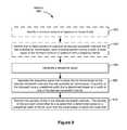
- FIG. 9illustrates a method 900 of transmitting a spread spectrum signal.
- the methodis performed at the transmitter (e.g., 102 in FIG. 4 ).
- the methodis performed at multiple devices (e.g., some of the operations are performed at a central unit while other operations are performed at the transmitter).
- a minimum amount of spectrum to transmit bitsis identified ( 902 ) (e.g., either by the transmitter or by the central unit).
- one or more portions of spectrum at discrete bandwidth intervals that are available for transmissionare identified ( 904 ) (e.g., either by the transmitter or by the central unit).
- the transmittergenerates ( 906 ) a respective signal.
- the transmitterseparates ( 908 ) the respective signal into multiple bits for transmission at the discrete bandwidth intervals that are available for transmission.
- a plurality of the bitseach have a predefined width that is determined based on a width of one of the discrete bandwidth intervals. In some embodiments, the plurality of bits includes all of the bits.
- the transmittertransmits ( 910 ) the plurality of bits in the discrete bandwidth intervals.
- the plurality of bitsare each transmitted for a duration that is determined based on a predefined width of the bit, such that the transmission is below the noise floor.
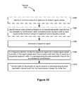
- FIG. 10illustrates a method 1000 of transmitting a spread spectrum signal.
- the methodis performed at the transmitter (e.g., 102 in FIG. 4 ).
- the methodis performed at multiple devices (e.g., some of the operations are performed at a central unit while other operations are performed at the transmitter).
- a minimum amount of spectrum to transmit bitsis identified ( 1002 ) (e.g., either by the transmitter or by the central unit).
- one or more portions of spectrum at discrete bandwidth intervals that are available for transmissionare identified ( 1004 ) (e.g., either by the transmitter or by the central unit).
- the transmittergenerates ( 1006 ) a respective signal.
- the transmitterdivides ( 1008 ) the respective signal into a plurality of signal pieces.
- a plurality of the signal pieceseach have a piece width less than or equal to a respective spectrum width of a corresponding discrete bandwidth interval that is available for transmission.
- the plurality of signal piecesincludes all of the signal pieces.
- the transmittertransmits ( 1010 ) each of the plurality of signal pieces at a corresponding discrete bandwidth interval such that the transmission is below the noise floor.
Landscapes
- Engineering & Computer Science (AREA)
- Computer Networks & Wireless Communication (AREA)
- Signal Processing (AREA)
- Physics & Mathematics (AREA)
- Astronomy & Astrophysics (AREA)
- Aviation & Aerospace Engineering (AREA)
- General Physics & Mathematics (AREA)
- Mobile Radio Communication Systems (AREA)
Abstract
Description
Claims (4)
Priority Applications (1)
| Application Number | Priority Date | Filing Date | Title |
|---|---|---|---|
| US12/890,578US8675711B1 (en) | 2009-09-25 | 2010-09-24 | System and methods for dynamic spread spectrum usage |
Applications Claiming Priority (2)
| Application Number | Priority Date | Filing Date | Title |
|---|---|---|---|
| US24606309P | 2009-09-25 | 2009-09-25 | |
| US12/890,578US8675711B1 (en) | 2009-09-25 | 2010-09-24 | System and methods for dynamic spread spectrum usage |
Publications (1)
| Publication Number | Publication Date |
|---|---|
| US8675711B1true US8675711B1 (en) | 2014-03-18 |
Family
ID=50240389
Family Applications (1)
| Application Number | Title | Priority Date | Filing Date |
|---|---|---|---|
| US12/890,578Active2031-05-31US8675711B1 (en) | 2009-09-25 | 2010-09-24 | System and methods for dynamic spread spectrum usage |
Country Status (1)
| Country | Link |
|---|---|
| US (1) | US8675711B1 (en) |
Cited By (5)
| Publication number | Priority date | Publication date | Assignee | Title |
|---|---|---|---|---|
| US20140293894A1 (en)* | 2013-03-28 | 2014-10-02 | Coming Optical Communications Wireless, Ltd. | Distributing dynamically frequency-shifted intermediate frequency (if) radio frequency (rf) communications signals in distributed antenna systems (dass), and related components, systems, and methods |
| US9813229B2 (en) | 2007-10-22 | 2017-11-07 | Corning Optical Communications Wireless Ltd | Communication system using low bandwidth wires |
| US9948329B2 (en) | 2012-03-23 | 2018-04-17 | Corning Optical Communications Wireless, LTD | Radio-frequency integrated circuit (RFIC) chip(s) for providing distributed antenna system functionalities, and related components, systems, and methods |
| WO2020131854A1 (en)* | 2018-12-17 | 2020-06-25 | Idac Holdings, Inc. | Communication in a resonance magnetic coupled system |
| US11121763B1 (en)* | 2020-04-10 | 2021-09-14 | Totum Labs, Inc. | System and method for downlink scheduling that optimizes downlink (DL) capacity |
Citations (154)
| Publication number | Priority date | Publication date | Assignee | Title |
|---|---|---|---|---|
| US4486739A (en) | 1982-06-30 | 1984-12-04 | International Business Machines Corporation | Byte oriented DC balanced (0,4) 8B/10B partitioned block transmission code |
| US4649396A (en) | 1985-08-26 | 1987-03-10 | Hazeltine Corporation | Double-tuned blade monopole |
| US4876737A (en) | 1986-11-26 | 1989-10-24 | Microdyne Corporation | Satellite data transmission and receiving station |
| US4901307A (en) | 1986-10-17 | 1990-02-13 | Qualcomm, Inc. | Spread spectrum multiple access communication system using satellite or terrestrial repeaters |
| US5109390A (en) | 1989-11-07 | 1992-04-28 | Qualcomm Incorporated | Diversity receiver in a cdma cellular telephone system |
| US5309474A (en) | 1990-06-25 | 1994-05-03 | Qualcomm Incorporated | System and method for generating signal waveforms in a CDMA cellular telephone system |
| US5376778A (en) | 1992-02-26 | 1994-12-27 | Angewandte Digital Electronik Gmbh | Contact-free chip card for remote transmission |
| US5490165A (en) | 1993-10-28 | 1996-02-06 | Qualcomm Incorporated | Demodulation element assignment in a system capable of receiving multiple signals |
| US5537397A (en) | 1994-06-07 | 1996-07-16 | Aloha Networks, Inc. | Spread aloha CDMA data communications |
| US5559790A (en) | 1993-07-23 | 1996-09-24 | Hitachi, Ltd. | Spread spectrum communication system and transmission power control method therefor |
| US5566168A (en) | 1994-01-11 | 1996-10-15 | Ericsson Ge Mobile Communications Inc. | TDMA/FDMA/CDMA hybrid radio access methods |
| US5568472A (en) | 1992-11-04 | 1996-10-22 | Ntt Mobile Communications Network Inc. | Code division multiple access mobile communication system |
| US5570350A (en)* | 1994-09-30 | 1996-10-29 | Lucent Technologies Inc. | CDMA cellular communications with multicarrier signal processing |
| US5594454A (en) | 1994-04-13 | 1997-01-14 | The Johns Hopkins University | Global positioning system (GPS) linked satellite and missile communication systems |
| US5612949A (en) | 1994-06-13 | 1997-03-18 | Hewlett-Packard Company | Method and apparatus for determining network delays |
| US5625629A (en) | 1995-08-07 | 1997-04-29 | Hughes Electronics | Method of ensuring bandwidth availability for non-page traffic in a communications systems |
| US5640166A (en) | 1996-09-03 | 1997-06-17 | Motorola, Inc. | Method for compensating for doppler frequency shifts for satellite communication systems |
| US5668556A (en) | 1991-10-02 | 1997-09-16 | Alcatel Espace | Low-orbit satellite communications system for terminals |
| US5694396A (en)* | 1994-09-30 | 1997-12-02 | Lucent Technologies Inc. | Method and apparatus for processing multicarrier signals |
| US5697050A (en) | 1995-08-23 | 1997-12-09 | Globalstar L.P. | Satellite beam steering reference using terrestrial beam steering terminals |
| US5724384A (en) | 1994-07-14 | 1998-03-03 | Samsung Electronics Co., Ltd. | PN code sync device using an adaptive threshold |
| US5790070A (en) | 1997-05-05 | 1998-08-04 | Motorola, Inc. | Network and method for controlling steerable beams |
| US5796777A (en) | 1996-02-27 | 1998-08-18 | Motorola, Inc. | Apparatus and method for digitizing and detecting a received radio frequency signal |
| US5815071A (en) | 1995-03-03 | 1998-09-29 | Qualcomm Incorporated | Method and apparatus for monitoring parameters of vehicle electronic control units |
| US5818883A (en)* | 1994-12-29 | 1998-10-06 | Motorola, Inc. | Multi-channel digital transceiver and method |
| US5835069A (en) | 1996-09-20 | 1998-11-10 | Trimble Navigation Limited | GPS antennas and receivers configured as handles for a surveyor's optical total station |
| US5841765A (en) | 1996-10-10 | 1998-11-24 | Skydata, Inc. | Demand-based connection management integrated services access terminal (ISAT) for satellite communication system |
| US5872777A (en) | 1997-09-30 | 1999-02-16 | Motorola, Inc. | Method and apparatus for conveying data packets in a packet data communication system |
| US5920278A (en) | 1997-05-28 | 1999-07-06 | Gregory D. Gibbons | Method and apparatus for identifying, locating, tracking, or communicating with remote objects |
| US5983111A (en) | 1997-07-08 | 1999-11-09 | Hughes Electronics Corporation | Adaptive constant false alarm rate system for detecting CDPD bursts |
| US5999561A (en)* | 1997-05-20 | 1999-12-07 | Sanconix, Inc. | Direct sequence spread spectrum method, computer-based product, apparatus and system tolerant to frequency reference offset |
| US6052561A (en) | 1998-02-23 | 2000-04-18 | Rudowicz; Michael James | Location method for a elective call receiver operating in a satellite communication system |
| US6084919A (en)* | 1998-01-30 | 2000-07-04 | Motorola, Inc. | Communication unit having spectral adaptability |
| US6088413A (en) | 1997-05-09 | 2000-07-11 | Alcatel | Apparatus for reducing jitter in a desynchronizer |
| US6100806A (en) | 1994-12-30 | 2000-08-08 | Advanced Business Sciences, Inc. | Apparatus and method for continuous electronic monitoring and tracking of individuals |
| US6121922A (en) | 1994-10-12 | 2000-09-19 | Veridian Erim International, Inc. | Tracking system using miniaturized concealable communications module |
| US6128276A (en)* | 1997-02-24 | 2000-10-03 | Radix Wireless, Inc. | Stacked-carrier discrete multiple tone communication technology and combinations with code nulling, interference cancellation, retrodirective communication and adaptive antenna arrays |
| US6128469A (en) | 1998-03-21 | 2000-10-03 | Aeroastro, Inc. | Satellite communication system with a sweeping high-gain antenna |
| US6151313A (en) | 1997-06-06 | 2000-11-21 | Aloha Networks, Inc. | Baseband phase estimation technique for demodulation of overlapping packets |
| US6163681A (en) | 1999-06-25 | 2000-12-19 | Harris Corporation | Wireless spread spectrum ground link-based aircraft data communication system with variable data rate |
| US6185245B1 (en) | 1999-01-15 | 2001-02-06 | Hyundai Electronics Industries Co., Ltd. | Synchronization acquisition apparatus and method thereof |
| US6188682B1 (en) | 1996-07-24 | 2001-02-13 | Ntt Mobile Communication Networks, Inc. | Method and apparatus for receiving CDMA radio communication |
| US6205167B1 (en) | 1997-12-23 | 2001-03-20 | Philips Electronics North America Corporation | Apparatus and method for code tracking in an IS-95 spread spectrum communications system |
| US6226531B1 (en) | 1998-08-24 | 2001-05-01 | Harris Corporation | High capacity broadband cellular/PCS base station using a phased array antenna |
| US6301316B1 (en)* | 1997-03-31 | 2001-10-09 | Mitsubishi Denki Kabushiki Kaisha | Frequency sharing mobile communication system equipped with diversity receiver incorporated with shared wave canceller |
| US6307840B1 (en) | 1997-09-19 | 2001-10-23 | Qualcomm Incorporated | Mobile station assisted timing synchronization in CDMA communication system |
| US6317029B1 (en) | 1998-08-07 | 2001-11-13 | Aeroastro, Llc | In situ remote sensing |
| US6339611B1 (en) | 1998-11-09 | 2002-01-15 | Qualcomm Inc. | Method and apparatus for cross polarized isolation in a communication system |
| US6349110B1 (en) | 1997-02-24 | 2002-02-19 | Golden Bridge Technology, Inc. | Subsystem and method for combining spread-spectrum multipath signals |
| US20020024965A1 (en) | 2000-08-28 | 2002-02-28 | Lg Electronics Inc. | Apparatus and method for automatic router configuration |
| US6353730B1 (en) | 1998-06-24 | 2002-03-05 | Uniden America Corporation | Automatic call to page conversion in a radio communication system |
| US6373831B1 (en) | 1997-03-26 | 2002-04-16 | Nortel Networks Ltd. | Systems and methods of channel coding and inverse-multiplexing for multi-carrier CDMA systems |
| USD455641S1 (en) | 1998-08-27 | 2002-04-16 | Schulte Corporation | Mounting bracket |
| US6396819B1 (en) | 1998-03-21 | 2002-05-28 | Richard D. Fleeter | Low-cost satellite communication system |
| US20020067759A1 (en)* | 2000-10-27 | 2002-06-06 | L-3 Communications Corporation | Efficient implementation of space division/multiple access for a synchronous CDMA communication system |
| US20020089434A1 (en) | 2000-11-06 | 2002-07-11 | Ohanes Ghazarian | Electronic vehicle product and personnel monitoring |
| US6421373B1 (en) | 1998-12-21 | 2002-07-16 | Kabushiki Kaisha Toshiba | Spread spectrum wireless communications device |
| US6438118B1 (en)* | 1997-06-25 | 2002-08-20 | Nec Corporation | Code-multiplexing communication apparatus |
| US20020173888A1 (en) | 2001-05-21 | 2002-11-21 | Shelton Robert Leo | Aircraft location and tracking system |
| US20020177476A1 (en) | 2001-05-22 | 2002-11-28 | Chou Y. Hong | Durable global asset-tracking device and a method of using the same |
| US20020191632A1 (en) | 2000-02-28 | 2002-12-19 | Mcdermott Scott A. | Spread-spectrum receiver with progressive fourier transform |
| US6507602B1 (en) | 1999-01-07 | 2003-01-14 | Ericsson, Inc. | Smoothing receiver channel estimates using spectral estimation |
| US6510172B1 (en) | 1997-03-04 | 2003-01-21 | Qualcomm, Inc. | Multi-user communication system architecture with distributed transmitters |
| US6529488B1 (en)* | 1998-08-18 | 2003-03-04 | Motorola, Inc. | Multiple frequency allocation radio frequency device and method |
| US20030053521A1 (en)* | 2001-09-17 | 2003-03-20 | Xiaojing Huang | System and electronic device for providing a multi-carrier spread spectrum signal |
| US20030063576A1 (en) | 2001-09-28 | 2003-04-03 | Interdigital Technology Corporation | Burst detector |
| US6549559B2 (en) | 1997-12-23 | 2003-04-15 | Koninklijke Philips Electronics N.V. | Apparatus and method for locking onto a psuedo-noise code in an IS-95 spread spectrum communications system |
| US6574205B1 (en) | 1998-05-01 | 2003-06-03 | Nec Corporation | CDMA cellular system and method of detecting spreading code in CDMA cellular system |
| US20030161428A1 (en) | 2002-02-22 | 2003-08-28 | Garrett Albert L. | Threshold detector for detecting synchronization signals at correlator output during packet acquisition |
| US6628699B2 (en) | 1997-06-23 | 2003-09-30 | Schlumberger Resource Management Systems, Inc. | Receiving a spread spectrum signal |
| US6639906B1 (en) | 1997-12-09 | 2003-10-28 | Jeffrey A. Levin | Multichannel demodulator |
| US20030204378A1 (en)* | 2001-06-26 | 2003-10-30 | Cai Khiem V. | System and method for forming a beam and creating nulls with an adaptive array antenna using orthogonal eigen-weighting |
| US20030202485A1 (en) | 2002-04-30 | 2003-10-30 | Carl Mansfield | Terminal assisted scheduling for time coordinated CDMA |
| US20030235148A1 (en)* | 2002-06-19 | 2003-12-25 | Yang George L. | Multi-channel spread spectrum communications system |
| US20040001534A1 (en)* | 2002-06-26 | 2004-01-01 | Yang George L. | Spread spectrum communication system with automatic rate detection |
| US20040008253A1 (en) | 2002-07-10 | 2004-01-15 | Monroe David A. | Comprehensive multi-media surveillance and response system for aircraft, operations centers, airports and other commercial transports, centers and terminals |
| US6683605B1 (en) | 1994-09-02 | 2004-01-27 | Nec Corporation | Screen saver disabler |
| US20040029615A1 (en) | 2000-09-26 | 2004-02-12 | Foster Gerry | Transmission of voice over packet-switched systems |
| US20040029579A1 (en) | 2002-08-07 | 2004-02-12 | Kyocera Corporation | Wireless communication system |
| EP1406207A1 (en) | 2002-10-04 | 2004-04-07 | Siemens Schweiz AG | Method for monitoring objects |
| US6720801B2 (en) | 2001-06-18 | 2004-04-13 | The United States Of America As Represented By The Secretary Of The Navy | RS-232 bus data tap apparatus |
| US6728298B1 (en) | 1999-07-14 | 2004-04-27 | Mitsubishi Denki Kabushiki Kaisha | Spread spectrum communication system and method for the same |
| US20040117611A1 (en) | 2000-06-27 | 2004-06-17 | Siegfried Huber | Method and arrangement for secure packet-oriented information transmission |
| US6754190B2 (en) | 2001-10-17 | 2004-06-22 | Motorola, Inc. | Channel selection method used in a communication system |
| US20040121729A1 (en) | 2002-10-24 | 2004-06-24 | Chris Herndon | Telecommunications infrastructure linkage method and system |
| US6763056B1 (en) | 1999-11-04 | 2004-07-13 | Nec Corporation | Path timing detection circuit and detection method thereof |
| US6768729B1 (en) | 1998-09-24 | 2004-07-27 | Nec Corporation | CDMA receiver, path detection method, and recording medium on which path detection control program is recorded |
| US20040183673A1 (en) | 2003-01-31 | 2004-09-23 | Nageli Hans Peter | Portable detachable self-contained tracking unit for two-way satellite communication with a central server |
| US6799094B1 (en) | 2002-09-03 | 2004-09-28 | Ridgeback Systems Llc | Aircraft location monitoring system and method of operation |
| US6826169B1 (en)* | 1996-12-20 | 2004-11-30 | Fujitsu Limited | Code multiplexing transmitting apparatus |
| US20050038601A1 (en) | 2003-08-13 | 2005-02-17 | Dentinger Michael P. | Method for standard positioning service and precise positioning service cooperative operation |
| US20050041573A1 (en) | 2003-07-30 | 2005-02-24 | Samsung Electronics Co., Ltd. | Ranging method in a broadband wireless access communication system |
| US20050060339A1 (en) | 2003-09-11 | 2005-03-17 | Saw Concepts Llc | Method to enable Heartbeat 911 |
| US6876645B1 (en) | 2000-07-05 | 2005-04-05 | Ericsson Inc. | Delay and channel estimation for multi-carrier CDMA system |
| US20050076034A1 (en) | 2003-10-07 | 2005-04-07 | Addonisio Louis Salvatore | Asset management and status system |
| US6894995B2 (en) | 2001-06-22 | 2005-05-17 | Interdigital Technology Corporation | Apparatus and method for performing initial cell search in wireless communication systems |
| US20050143005A1 (en) | 2003-12-29 | 2005-06-30 | Peersat Llc. | Inter-satellite crosslink communications system, apparatus, method and computer program product |
| US20050176436A1 (en) | 2004-02-05 | 2005-08-11 | Ashok Mantravadi | Channel estimation for a wireless communication system with multiple parallel data streams |
| US20050175123A1 (en) | 2004-02-11 | 2005-08-11 | Gurney David P. | Method and apparatus for improved burst acquisition in a digital receiver |
| US6944149B1 (en) | 1998-09-24 | 2005-09-13 | Samsung Electronics Co., Ltd. | Apparatus and method or searching for PN sequence phase in multi-carrier CDMA mobile communication system |
| US20050201326A1 (en)* | 2001-12-06 | 2005-09-15 | Lakkis Ismail A. | Systems and methods for wireless communication over a wide bandwidth channel using a plurality of sub-channels |
| US20050201311A1 (en) | 2003-12-08 | 2005-09-15 | Willey William D. | Methods and apparatus for providing a tolerable delay for slotted messages in wireless communication networks |
| DE102004016548A1 (en) | 2004-03-31 | 2005-10-27 | Francotyp-Postalia Ag & Co. Kg | Process to store unfalsified record of goods surrendered for delivery and check against final delivery records |
| US20050248456A1 (en) | 2004-05-06 | 2005-11-10 | Britton Charles L Jr | Space charge dosimeters for extremely low power measurements of radiation in shipping containers |
| US20050281319A1 (en) | 1996-08-02 | 2005-12-22 | Golden Bridge Technology Inc. | Packet spread-spectrum receiver |
| US6985512B1 (en) | 2000-02-28 | 2006-01-10 | Aeroastro, Inc. | Asynchronous spread-spectrum communications |
| US7006032B2 (en) | 2004-01-15 | 2006-02-28 | Honeywell International, Inc. | Integrated traffic surveillance apparatus |
| US20060055561A1 (en) | 2004-09-10 | 2006-03-16 | Kamali Tayeb A | Automatic speed violation detection and response system using wireless communication, positioning and RF ID |
| US20060094450A1 (en) | 2004-02-11 | 2006-05-04 | Samsung Electronics Co., Ltd. | Method for controlling an operation mode of a mobile terminal in a broadband wireless access communication system |
| US7053767B2 (en) | 1998-06-22 | 2006-05-30 | Statsignal Systems, Inc. | System and method for monitoring and controlling remote devices |
| US20060141930A1 (en) | 2004-12-28 | 2006-06-29 | Livetv, Llc | Aircraft in-flight entertainment system including low power transceivers and associated methods |
| US20060140314A1 (en) | 2004-12-27 | 2006-06-29 | Samsung Electronics Co., Ltd. | Signal acquisition apparatus and method for reducing false alarm rate |
| US20060187026A1 (en) | 2002-05-07 | 2006-08-24 | Gary Kochis | Tracking system and associated method |
| US7110435B1 (en) | 1999-03-15 | 2006-09-19 | Parkervision, Inc. | Spread spectrum applications of universal frequency translation |
| US20060233147A1 (en)* | 2004-12-07 | 2006-10-19 | Mobile Satellite Ventures, Lp | Broadband wireless communications systems and methods using multiple non-contiguous frequency bands/segments |
| US20060251107A1 (en) | 2005-04-21 | 2006-11-09 | Geren Bruce E | Method and system for collision avoidance in wireless communications |
| US20070031150A1 (en) | 2005-08-02 | 2007-02-08 | Donald Fisher | Communication transceiver architecture |
| US20070040647A1 (en) | 2005-08-17 | 2007-02-22 | Wireless Data Solutions, Llc | System for monitoring and control of transport containers |
| US20070064641A1 (en)* | 2004-04-23 | 2007-03-22 | Rajiv Laroia | Methods and apparatus of enhancing performance in wireless communication systems |
| US7203630B2 (en) | 2002-11-11 | 2007-04-10 | Aeromechanical Services Ltd. | Aircraft flight data management system |
| US20070086335A1 (en)* | 2005-07-28 | 2007-04-19 | Riverbed Technology, Inc. | Congestion management over lossy network connections |
| US20070117515A1 (en) | 2005-11-23 | 2007-05-24 | Sr Technologies, Inc. | Burst processor method and apparatus |
| US20070116158A1 (en) | 2005-11-21 | 2007-05-24 | Yongfang Guo | Packet detection in the presence of platform noise in a wireless network |
| US7236778B2 (en) | 2002-09-10 | 2007-06-26 | Northrop Grumman Corporation | System and method for testing transceivers |
| US20070202816A1 (en)* | 2006-02-28 | 2007-08-30 | Dunmin Zheng | Systems, methods and transceivers for wireless communications over discontiguous spectrum segments |
| US20070223425A1 (en)* | 1995-08-10 | 2007-09-27 | Hironari Masui | CDMA mobile communication system and communication method |
| USD554474S1 (en) | 2006-04-17 | 2007-11-06 | Electric Pump, Inc. | Equipment mounting pad |
| US20070293149A1 (en) | 2006-06-16 | 2007-12-20 | Roy Wubker | Portable handheld satellite phone conversion module |
| US20070291826A1 (en) | 2006-06-14 | 2007-12-20 | Oki Electric Industry Co., Ltd. | Spread spectrum receiver for restoring received symbols with a symbol detection window adjusted in optimal and a method therefor |
| US20070298786A1 (en) | 2005-11-02 | 2007-12-27 | Comtech Mobile Datacom Corporation | In-flight transceiver and locator system |
| US20080030345A1 (en) | 2007-05-24 | 2008-02-07 | Smith & Nephew, Inc. | System and method for tracking surgical assets |
| US7394870B2 (en) | 2003-04-04 | 2008-07-01 | Silicon Storage Technology, Inc. | Low complexity synchronization for wireless transmission |
| US20080181170A1 (en) | 2001-03-06 | 2008-07-31 | Branlund Dale A | Adaptive Communications Methods for Multiple User Packet Radio Wireless Networks |
| USD574221S1 (en) | 2007-06-27 | 2008-08-05 | Peter Allen | Locking bracket for a portable electronic device |
| US7430257B1 (en)* | 1998-02-12 | 2008-09-30 | Lot 41 Acquisition Foundation, Llc | Multicarrier sub-layer for direct sequence channel and multiple-access coding |
| US7433391B2 (en) | 2000-02-28 | 2008-10-07 | Aeroastro, Inc. | Spread-spectrum receiver with fast M-sequence transform |
| USD582918S1 (en) | 2006-09-08 | 2008-12-16 | Coolit Systems Inc. | Computer device mounting clip |
| US20090046771A1 (en) | 2005-05-27 | 2009-02-19 | Matsushita Electric Industrial Co., Ltd. | Reception quality estimating apparatus, wireless communication system, and reception quality estimating method |
| US20090135954A1 (en) | 2007-11-28 | 2009-05-28 | Go Networks, Inc. | Dynamic threshold detector |
| US20090175299A1 (en) | 2006-04-26 | 2009-07-09 | Shuya Hosokawa | Signal detection device and signal detection method |
| US7592953B2 (en) | 2005-12-30 | 2009-09-22 | Comtech Mobile Datacom Corporation | Mobile satellite communications |
| US20090238246A1 (en)* | 2008-03-20 | 2009-09-24 | Infineon Technologies Ag | Diversity receiver |
| US20090257517A1 (en)* | 2008-04-14 | 2009-10-15 | Telefonaktiebolaget Lm Ericsson (Publ) | Wireless communication methods and receivers for receiving and processing multiple component carrier signals |
| US20090279620A1 (en)* | 2008-05-09 | 2009-11-12 | Infineon Technologies Ag | Data communication |
| US20090298422A1 (en)* | 2008-05-30 | 2009-12-03 | Qualcomm Incorporated | Calibration Using Noise Power |
| US20090316759A1 (en) | 2003-03-03 | 2009-12-24 | Interdigital Technology Corporation | Multi-user detection using equalization and successive interference cancellation |
| US20100064091A1 (en)* | 2008-09-11 | 2010-03-11 | Sony Corporation | Information processing apparatus and method |
| US7706748B2 (en)* | 2004-06-25 | 2010-04-27 | Atc Technologies, Llc | Methods of ground based beamforming and on-board frequency translation and related systems |
| US20100166180A1 (en) | 2008-12-30 | 2010-07-01 | Nortel Networks Limited | Cloaking of radio signals |
| US7848458B2 (en)* | 2005-02-18 | 2010-12-07 | Mitsubishi Electric Corporation | Communication apparatus |
| US20100322334A1 (en)* | 2008-03-10 | 2010-12-23 | Koninklijke Philips Electronics, N.V. | Efficient multi-band communication system |
| US7876259B2 (en)* | 2006-11-06 | 2011-01-25 | Leonard Schuchman | Automatic dependent surveillance system secure ADS-S |
| US20110038261A1 (en)* | 2008-04-24 | 2011-02-17 | Carlstroem Jakob | Traffic manager and a method for a traffic manager |
| US8054866B2 (en)* | 2006-01-17 | 2011-11-08 | The Doshisha | MC-CDMA system, transmitter and receiver |
- 2010
- 2010-09-24USUS12/890,578patent/US8675711B1/enactiveActive
Patent Citations (163)
| Publication number | Priority date | Publication date | Assignee | Title |
|---|---|---|---|---|
| US4486739A (en) | 1982-06-30 | 1984-12-04 | International Business Machines Corporation | Byte oriented DC balanced (0,4) 8B/10B partitioned block transmission code |
| US4649396A (en) | 1985-08-26 | 1987-03-10 | Hazeltine Corporation | Double-tuned blade monopole |
| US4901307A (en) | 1986-10-17 | 1990-02-13 | Qualcomm, Inc. | Spread spectrum multiple access communication system using satellite or terrestrial repeaters |
| US4876737A (en) | 1986-11-26 | 1989-10-24 | Microdyne Corporation | Satellite data transmission and receiving station |
| US5109390A (en) | 1989-11-07 | 1992-04-28 | Qualcomm Incorporated | Diversity receiver in a cdma cellular telephone system |
| US5309474A (en) | 1990-06-25 | 1994-05-03 | Qualcomm Incorporated | System and method for generating signal waveforms in a CDMA cellular telephone system |
| US5668556A (en) | 1991-10-02 | 1997-09-16 | Alcatel Espace | Low-orbit satellite communications system for terminals |
| US5376778A (en) | 1992-02-26 | 1994-12-27 | Angewandte Digital Electronik Gmbh | Contact-free chip card for remote transmission |
| US5568472A (en) | 1992-11-04 | 1996-10-22 | Ntt Mobile Communications Network Inc. | Code division multiple access mobile communication system |
| US5559790A (en) | 1993-07-23 | 1996-09-24 | Hitachi, Ltd. | Spread spectrum communication system and transmission power control method therefor |
| US5490165A (en) | 1993-10-28 | 1996-02-06 | Qualcomm Incorporated | Demodulation element assignment in a system capable of receiving multiple signals |
| US5566168A (en) | 1994-01-11 | 1996-10-15 | Ericsson Ge Mobile Communications Inc. | TDMA/FDMA/CDMA hybrid radio access methods |
| US5594454A (en) | 1994-04-13 | 1997-01-14 | The Johns Hopkins University | Global positioning system (GPS) linked satellite and missile communication systems |
| US5537397A (en) | 1994-06-07 | 1996-07-16 | Aloha Networks, Inc. | Spread aloha CDMA data communications |
| US5612949A (en) | 1994-06-13 | 1997-03-18 | Hewlett-Packard Company | Method and apparatus for determining network delays |
| US5724384A (en) | 1994-07-14 | 1998-03-03 | Samsung Electronics Co., Ltd. | PN code sync device using an adaptive threshold |
| US6683605B1 (en) | 1994-09-02 | 2004-01-27 | Nec Corporation | Screen saver disabler |
| US5570350A (en)* | 1994-09-30 | 1996-10-29 | Lucent Technologies Inc. | CDMA cellular communications with multicarrier signal processing |
| US5694396A (en)* | 1994-09-30 | 1997-12-02 | Lucent Technologies Inc. | Method and apparatus for processing multicarrier signals |
| US6121922A (en) | 1994-10-12 | 2000-09-19 | Veridian Erim International, Inc. | Tracking system using miniaturized concealable communications module |
| US5818883A (en)* | 1994-12-29 | 1998-10-06 | Motorola, Inc. | Multi-channel digital transceiver and method |
| US6100806A (en) | 1994-12-30 | 2000-08-08 | Advanced Business Sciences, Inc. | Apparatus and method for continuous electronic monitoring and tracking of individuals |
| US5815071A (en) | 1995-03-03 | 1998-09-29 | Qualcomm Incorporated | Method and apparatus for monitoring parameters of vehicle electronic control units |
| US5625629A (en) | 1995-08-07 | 1997-04-29 | Hughes Electronics | Method of ensuring bandwidth availability for non-page traffic in a communications systems |
| US20070223425A1 (en)* | 1995-08-10 | 2007-09-27 | Hironari Masui | CDMA mobile communication system and communication method |
| US5758260A (en) | 1995-08-23 | 1998-05-26 | Globalstar L.P. | Satellite beam steering reference using terrestrial beam steering terminals |
| US5697050A (en) | 1995-08-23 | 1997-12-09 | Globalstar L.P. | Satellite beam steering reference using terrestrial beam steering terminals |
| US5796777A (en) | 1996-02-27 | 1998-08-18 | Motorola, Inc. | Apparatus and method for digitizing and detecting a received radio frequency signal |
| US6188682B1 (en) | 1996-07-24 | 2001-02-13 | Ntt Mobile Communication Networks, Inc. | Method and apparatus for receiving CDMA radio communication |
| US20050281319A1 (en) | 1996-08-02 | 2005-12-22 | Golden Bridge Technology Inc. | Packet spread-spectrum receiver |
| US5640166A (en) | 1996-09-03 | 1997-06-17 | Motorola, Inc. | Method for compensating for doppler frequency shifts for satellite communication systems |
| US5835069A (en) | 1996-09-20 | 1998-11-10 | Trimble Navigation Limited | GPS antennas and receivers configured as handles for a surveyor's optical total station |
| US5841765A (en) | 1996-10-10 | 1998-11-24 | Skydata, Inc. | Demand-based connection management integrated services access terminal (ISAT) for satellite communication system |
| US6826169B1 (en)* | 1996-12-20 | 2004-11-30 | Fujitsu Limited | Code multiplexing transmitting apparatus |
| US6349110B1 (en) | 1997-02-24 | 2002-02-19 | Golden Bridge Technology, Inc. | Subsystem and method for combining spread-spectrum multipath signals |
| US6128276A (en)* | 1997-02-24 | 2000-10-03 | Radix Wireless, Inc. | Stacked-carrier discrete multiple tone communication technology and combinations with code nulling, interference cancellation, retrodirective communication and adaptive antenna arrays |
| US20030123384A1 (en)* | 1997-02-24 | 2003-07-03 | Agee Brian G. | Stacked-carrier discrete multiple tone communication technology and combinations with code nulling, interference cancellation, retrodirective communication and adaptive antenna arrays |
| US6510172B1 (en) | 1997-03-04 | 2003-01-21 | Qualcomm, Inc. | Multi-user communication system architecture with distributed transmitters |
| US6373831B1 (en) | 1997-03-26 | 2002-04-16 | Nortel Networks Ltd. | Systems and methods of channel coding and inverse-multiplexing for multi-carrier CDMA systems |
| US6301316B1 (en)* | 1997-03-31 | 2001-10-09 | Mitsubishi Denki Kabushiki Kaisha | Frequency sharing mobile communication system equipped with diversity receiver incorporated with shared wave canceller |
| US5790070A (en) | 1997-05-05 | 1998-08-04 | Motorola, Inc. | Network and method for controlling steerable beams |
| US6088413A (en) | 1997-05-09 | 2000-07-11 | Alcatel | Apparatus for reducing jitter in a desynchronizer |
| US5999561A (en)* | 1997-05-20 | 1999-12-07 | Sanconix, Inc. | Direct sequence spread spectrum method, computer-based product, apparatus and system tolerant to frequency reference offset |
| US5920278A (en) | 1997-05-28 | 1999-07-06 | Gregory D. Gibbons | Method and apparatus for identifying, locating, tracking, or communicating with remote objects |
| US6151313A (en) | 1997-06-06 | 2000-11-21 | Aloha Networks, Inc. | Baseband phase estimation technique for demodulation of overlapping packets |
| US6628699B2 (en) | 1997-06-23 | 2003-09-30 | Schlumberger Resource Management Systems, Inc. | Receiving a spread spectrum signal |
| US6438118B1 (en)* | 1997-06-25 | 2002-08-20 | Nec Corporation | Code-multiplexing communication apparatus |
| US5983111A (en) | 1997-07-08 | 1999-11-09 | Hughes Electronics Corporation | Adaptive constant false alarm rate system for detecting CDPD bursts |
| US6307840B1 (en) | 1997-09-19 | 2001-10-23 | Qualcomm Incorporated | Mobile station assisted timing synchronization in CDMA communication system |
| US5872777A (en) | 1997-09-30 | 1999-02-16 | Motorola, Inc. | Method and apparatus for conveying data packets in a packet data communication system |
| US6639906B1 (en) | 1997-12-09 | 2003-10-28 | Jeffrey A. Levin | Multichannel demodulator |
| US6205167B1 (en) | 1997-12-23 | 2001-03-20 | Philips Electronics North America Corporation | Apparatus and method for code tracking in an IS-95 spread spectrum communications system |
| US6549559B2 (en) | 1997-12-23 | 2003-04-15 | Koninklijke Philips Electronics N.V. | Apparatus and method for locking onto a psuedo-noise code in an IS-95 spread spectrum communications system |
| US6084919A (en)* | 1998-01-30 | 2000-07-04 | Motorola, Inc. | Communication unit having spectral adaptability |
| US7430257B1 (en)* | 1998-02-12 | 2008-09-30 | Lot 41 Acquisition Foundation, Llc | Multicarrier sub-layer for direct sequence channel and multiple-access coding |
| US6052561A (en) | 1998-02-23 | 2000-04-18 | Rudowicz; Michael James | Location method for a elective call receiver operating in a satellite communication system |
| US20020097690A1 (en) | 1998-03-21 | 2002-07-25 | Fleeter Richard D. | Low-cost satellite communication system |
| US6128469A (en) | 1998-03-21 | 2000-10-03 | Aeroastro, Inc. | Satellite communication system with a sweeping high-gain antenna |
| US6396819B1 (en) | 1998-03-21 | 2002-05-28 | Richard D. Fleeter | Low-cost satellite communication system |
| US6574205B1 (en) | 1998-05-01 | 2003-06-03 | Nec Corporation | CDMA cellular system and method of detecting spreading code in CDMA cellular system |
| US7053767B2 (en) | 1998-06-22 | 2006-05-30 | Statsignal Systems, Inc. | System and method for monitoring and controlling remote devices |
| US6353730B1 (en) | 1998-06-24 | 2002-03-05 | Uniden America Corporation | Automatic call to page conversion in a radio communication system |
| US6317029B1 (en) | 1998-08-07 | 2001-11-13 | Aeroastro, Llc | In situ remote sensing |
| US6529488B1 (en)* | 1998-08-18 | 2003-03-04 | Motorola, Inc. | Multiple frequency allocation radio frequency device and method |
| US6226531B1 (en) | 1998-08-24 | 2001-05-01 | Harris Corporation | High capacity broadband cellular/PCS base station using a phased array antenna |
| USD455641S1 (en) | 1998-08-27 | 2002-04-16 | Schulte Corporation | Mounting bracket |
| US6768729B1 (en) | 1998-09-24 | 2004-07-27 | Nec Corporation | CDMA receiver, path detection method, and recording medium on which path detection control program is recorded |
| US6944149B1 (en) | 1998-09-24 | 2005-09-13 | Samsung Electronics Co., Ltd. | Apparatus and method or searching for PN sequence phase in multi-carrier CDMA mobile communication system |
| US6339611B1 (en) | 1998-11-09 | 2002-01-15 | Qualcomm Inc. | Method and apparatus for cross polarized isolation in a communication system |
| US6421373B1 (en) | 1998-12-21 | 2002-07-16 | Kabushiki Kaisha Toshiba | Spread spectrum wireless communications device |
| US6507602B1 (en) | 1999-01-07 | 2003-01-14 | Ericsson, Inc. | Smoothing receiver channel estimates using spectral estimation |
| US6185245B1 (en) | 1999-01-15 | 2001-02-06 | Hyundai Electronics Industries Co., Ltd. | Synchronization acquisition apparatus and method thereof |
| US7110435B1 (en) | 1999-03-15 | 2006-09-19 | Parkervision, Inc. | Spread spectrum applications of universal frequency translation |
| US6163681A (en) | 1999-06-25 | 2000-12-19 | Harris Corporation | Wireless spread spectrum ground link-based aircraft data communication system with variable data rate |
| US6728298B1 (en) | 1999-07-14 | 2004-04-27 | Mitsubishi Denki Kabushiki Kaisha | Spread spectrum communication system and method for the same |
| US6763056B1 (en) | 1999-11-04 | 2004-07-13 | Nec Corporation | Path timing detection circuit and detection method thereof |
| US20020191632A1 (en) | 2000-02-28 | 2002-12-19 | Mcdermott Scott A. | Spread-spectrum receiver with progressive fourier transform |
| US6985512B1 (en) | 2000-02-28 | 2006-01-10 | Aeroastro, Inc. | Asynchronous spread-spectrum communications |
| US7433391B2 (en) | 2000-02-28 | 2008-10-07 | Aeroastro, Inc. | Spread-spectrum receiver with fast M-sequence transform |
| US7227884B2 (en) | 2000-02-28 | 2007-06-05 | Aeroastro, Inc. | Spread-spectrum receiver with progressive fourier transform |
| US20040117611A1 (en) | 2000-06-27 | 2004-06-17 | Siegfried Huber | Method and arrangement for secure packet-oriented information transmission |
| US6876645B1 (en) | 2000-07-05 | 2005-04-05 | Ericsson Inc. | Delay and channel estimation for multi-carrier CDMA system |
| US20020024965A1 (en) | 2000-08-28 | 2002-02-28 | Lg Electronics Inc. | Apparatus and method for automatic router configuration |
| US20040029615A1 (en) | 2000-09-26 | 2004-02-12 | Foster Gerry | Transmission of voice over packet-switched systems |
| US20020067759A1 (en)* | 2000-10-27 | 2002-06-06 | L-3 Communications Corporation | Efficient implementation of space division/multiple access for a synchronous CDMA communication system |
| US20020089434A1 (en) | 2000-11-06 | 2002-07-11 | Ohanes Ghazarian | Electronic vehicle product and personnel monitoring |
| US20080181170A1 (en) | 2001-03-06 | 2008-07-31 | Branlund Dale A | Adaptive Communications Methods for Multiple User Packet Radio Wireless Networks |
| US20020173888A1 (en) | 2001-05-21 | 2002-11-21 | Shelton Robert Leo | Aircraft location and tracking system |
| US20020177476A1 (en) | 2001-05-22 | 2002-11-28 | Chou Y. Hong | Durable global asset-tracking device and a method of using the same |
| US6720801B2 (en) | 2001-06-18 | 2004-04-13 | The United States Of America As Represented By The Secretary Of The Navy | RS-232 bus data tap apparatus |
| US6894995B2 (en) | 2001-06-22 | 2005-05-17 | Interdigital Technology Corporation | Apparatus and method for performing initial cell search in wireless communication systems |
| US20030204378A1 (en)* | 2001-06-26 | 2003-10-30 | Cai Khiem V. | System and method for forming a beam and creating nulls with an adaptive array antenna using orthogonal eigen-weighting |
| US20030053521A1 (en)* | 2001-09-17 | 2003-03-20 | Xiaojing Huang | System and electronic device for providing a multi-carrier spread spectrum signal |
| US20030063576A1 (en) | 2001-09-28 | 2003-04-03 | Interdigital Technology Corporation | Burst detector |
| US6754190B2 (en) | 2001-10-17 | 2004-06-22 | Motorola, Inc. | Channel selection method used in a communication system |
| US20080043653A1 (en)* | 2001-12-06 | 2008-02-21 | Lakkis Ismail A | Systems and methods for wireless communication over a wide bandwidth channel using a plurality of sub-channels |
| US20050201326A1 (en)* | 2001-12-06 | 2005-09-15 | Lakkis Ismail A. | Systems and methods for wireless communication over a wide bandwidth channel using a plurality of sub-channels |
| US20030161428A1 (en) | 2002-02-22 | 2003-08-28 | Garrett Albert L. | Threshold detector for detecting synchronization signals at correlator output during packet acquisition |
| US20030202485A1 (en) | 2002-04-30 | 2003-10-30 | Carl Mansfield | Terminal assisted scheduling for time coordinated CDMA |
| US20060187026A1 (en) | 2002-05-07 | 2006-08-24 | Gary Kochis | Tracking system and associated method |
| US20030235148A1 (en)* | 2002-06-19 | 2003-12-25 | Yang George L. | Multi-channel spread spectrum communications system |
| US20040001534A1 (en)* | 2002-06-26 | 2004-01-01 | Yang George L. | Spread spectrum communication system with automatic rate detection |
| US20040008253A1 (en) | 2002-07-10 | 2004-01-15 | Monroe David A. | Comprehensive multi-media surveillance and response system for aircraft, operations centers, airports and other commercial transports, centers and terminals |
| US7131136B2 (en) | 2002-07-10 | 2006-10-31 | E-Watch, Inc. | Comprehensive multi-media surveillance and response system for aircraft, operations centers, airports and other commercial transports, centers and terminals |
| US20070130599A1 (en) | 2002-07-10 | 2007-06-07 | Monroe David A | Comprehensive multi-media surveillance and response system for aircraft, operations centers, airports and other commercial transports, centers and terminals |
| US20040029579A1 (en) | 2002-08-07 | 2004-02-12 | Kyocera Corporation | Wireless communication system |
| US6799094B1 (en) | 2002-09-03 | 2004-09-28 | Ridgeback Systems Llc | Aircraft location monitoring system and method of operation |
| US7236778B2 (en) | 2002-09-10 | 2007-06-26 | Northrop Grumman Corporation | System and method for testing transceivers |
| US20040246104A1 (en) | 2002-10-04 | 2004-12-09 | Rolf Baechtiger | Method for monitoring goods |
| EP1406207A1 (en) | 2002-10-04 | 2004-04-07 | Siemens Schweiz AG | Method for monitoring objects |
| US20040121729A1 (en) | 2002-10-24 | 2004-06-24 | Chris Herndon | Telecommunications infrastructure linkage method and system |
| US7203630B2 (en) | 2002-11-11 | 2007-04-10 | Aeromechanical Services Ltd. | Aircraft flight data management system |
| US20040183673A1 (en) | 2003-01-31 | 2004-09-23 | Nageli Hans Peter | Portable detachable self-contained tracking unit for two-way satellite communication with a central server |
| US20090316759A1 (en) | 2003-03-03 | 2009-12-24 | Interdigital Technology Corporation | Multi-user detection using equalization and successive interference cancellation |
| US7394870B2 (en) | 2003-04-04 | 2008-07-01 | Silicon Storage Technology, Inc. | Low complexity synchronization for wireless transmission |
| US20050041573A1 (en) | 2003-07-30 | 2005-02-24 | Samsung Electronics Co., Ltd. | Ranging method in a broadband wireless access communication system |
| US20050038601A1 (en) | 2003-08-13 | 2005-02-17 | Dentinger Michael P. | Method for standard positioning service and precise positioning service cooperative operation |
| US20050060339A1 (en) | 2003-09-11 | 2005-03-17 | Saw Concepts Llc | Method to enable Heartbeat 911 |
| US20050076034A1 (en) | 2003-10-07 | 2005-04-07 | Addonisio Louis Salvatore | Asset management and status system |
| US20050201311A1 (en) | 2003-12-08 | 2005-09-15 | Willey William D. | Methods and apparatus for providing a tolerable delay for slotted messages in wireless communication networks |
| US20050143005A1 (en) | 2003-12-29 | 2005-06-30 | Peersat Llc. | Inter-satellite crosslink communications system, apparatus, method and computer program product |
| US7006032B2 (en) | 2004-01-15 | 2006-02-28 | Honeywell International, Inc. | Integrated traffic surveillance apparatus |
| US20050176436A1 (en) | 2004-02-05 | 2005-08-11 | Ashok Mantravadi | Channel estimation for a wireless communication system with multiple parallel data streams |
| US20050175123A1 (en) | 2004-02-11 | 2005-08-11 | Gurney David P. | Method and apparatus for improved burst acquisition in a digital receiver |
| US20060094450A1 (en) | 2004-02-11 | 2006-05-04 | Samsung Electronics Co., Ltd. | Method for controlling an operation mode of a mobile terminal in a broadband wireless access communication system |
| DE102004016548A1 (en) | 2004-03-31 | 2005-10-27 | Francotyp-Postalia Ag & Co. Kg | Process to store unfalsified record of goods surrendered for delivery and check against final delivery records |
| US20070064641A1 (en)* | 2004-04-23 | 2007-03-22 | Rajiv Laroia | Methods and apparatus of enhancing performance in wireless communication systems |
| US20050248456A1 (en) | 2004-05-06 | 2005-11-10 | Britton Charles L Jr | Space charge dosimeters for extremely low power measurements of radiation in shipping containers |
| US7706748B2 (en)* | 2004-06-25 | 2010-04-27 | Atc Technologies, Llc | Methods of ground based beamforming and on-board frequency translation and related systems |
| US20060055561A1 (en) | 2004-09-10 | 2006-03-16 | Kamali Tayeb A | Automatic speed violation detection and response system using wireless communication, positioning and RF ID |
| US20090042516A1 (en)* | 2004-12-07 | 2009-02-12 | Atc Technologies, Llc | Broadband wireless communications systems and methods using multiple non-contiguous frequency bands/segments |
| US20060233147A1 (en)* | 2004-12-07 | 2006-10-19 | Mobile Satellite Ventures, Lp | Broadband wireless communications systems and methods using multiple non-contiguous frequency bands/segments |
| US20060140314A1 (en) | 2004-12-27 | 2006-06-29 | Samsung Electronics Co., Ltd. | Signal acquisition apparatus and method for reducing false alarm rate |
| US20060141930A1 (en) | 2004-12-28 | 2006-06-29 | Livetv, Llc | Aircraft in-flight entertainment system including low power transceivers and associated methods |
| US7848458B2 (en)* | 2005-02-18 | 2010-12-07 | Mitsubishi Electric Corporation | Communication apparatus |
| US20060251107A1 (en) | 2005-04-21 | 2006-11-09 | Geren Bruce E | Method and system for collision avoidance in wireless communications |
| US20090046771A1 (en) | 2005-05-27 | 2009-02-19 | Matsushita Electric Industrial Co., Ltd. | Reception quality estimating apparatus, wireless communication system, and reception quality estimating method |
| US20070086335A1 (en)* | 2005-07-28 | 2007-04-19 | Riverbed Technology, Inc. | Congestion management over lossy network connections |
| US20070031150A1 (en) | 2005-08-02 | 2007-02-08 | Donald Fisher | Communication transceiver architecture |
| US20070040647A1 (en) | 2005-08-17 | 2007-02-22 | Wireless Data Solutions, Llc | System for monitoring and control of transport containers |
| US20070298786A1 (en) | 2005-11-02 | 2007-12-27 | Comtech Mobile Datacom Corporation | In-flight transceiver and locator system |
| US20070116158A1 (en) | 2005-11-21 | 2007-05-24 | Yongfang Guo | Packet detection in the presence of platform noise in a wireless network |
| US20070117515A1 (en) | 2005-11-23 | 2007-05-24 | Sr Technologies, Inc. | Burst processor method and apparatus |
| US7592953B2 (en) | 2005-12-30 | 2009-09-22 | Comtech Mobile Datacom Corporation | Mobile satellite communications |
| US8054866B2 (en)* | 2006-01-17 | 2011-11-08 | The Doshisha | MC-CDMA system, transmitter and receiver |
| US20070202816A1 (en)* | 2006-02-28 | 2007-08-30 | Dunmin Zheng | Systems, methods and transceivers for wireless communications over discontiguous spectrum segments |
| USD554474S1 (en) | 2006-04-17 | 2007-11-06 | Electric Pump, Inc. | Equipment mounting pad |
| US20090175299A1 (en) | 2006-04-26 | 2009-07-09 | Shuya Hosokawa | Signal detection device and signal detection method |
| US20070291826A1 (en) | 2006-06-14 | 2007-12-20 | Oki Electric Industry Co., Ltd. | Spread spectrum receiver for restoring received symbols with a symbol detection window adjusted in optimal and a method therefor |
| US20070293149A1 (en) | 2006-06-16 | 2007-12-20 | Roy Wubker | Portable handheld satellite phone conversion module |
| USD582918S1 (en) | 2006-09-08 | 2008-12-16 | Coolit Systems Inc. | Computer device mounting clip |
| US7876259B2 (en)* | 2006-11-06 | 2011-01-25 | Leonard Schuchman | Automatic dependent surveillance system secure ADS-S |
| US20080030345A1 (en) | 2007-05-24 | 2008-02-07 | Smith & Nephew, Inc. | System and method for tracking surgical assets |
| USD574221S1 (en) | 2007-06-27 | 2008-08-05 | Peter Allen | Locking bracket for a portable electronic device |
| US20090135954A1 (en) | 2007-11-28 | 2009-05-28 | Go Networks, Inc. | Dynamic threshold detector |
| US20100322334A1 (en)* | 2008-03-10 | 2010-12-23 | Koninklijke Philips Electronics, N.V. | Efficient multi-band communication system |
| US20090238246A1 (en)* | 2008-03-20 | 2009-09-24 | Infineon Technologies Ag | Diversity receiver |
| US20090257517A1 (en)* | 2008-04-14 | 2009-10-15 | Telefonaktiebolaget Lm Ericsson (Publ) | Wireless communication methods and receivers for receiving and processing multiple component carrier signals |
| US20110038261A1 (en)* | 2008-04-24 | 2011-02-17 | Carlstroem Jakob | Traffic manager and a method for a traffic manager |
| US20090279620A1 (en)* | 2008-05-09 | 2009-11-12 | Infineon Technologies Ag | Data communication |
| US20090298422A1 (en)* | 2008-05-30 | 2009-12-03 | Qualcomm Incorporated | Calibration Using Noise Power |
| US20100064091A1 (en)* | 2008-09-11 | 2010-03-11 | Sony Corporation | Information processing apparatus and method |
| US20100166180A1 (en) | 2008-12-30 | 2010-07-01 | Nortel Networks Limited | Cloaking of radio signals |
Non-Patent Citations (74)
| Title |
|---|
| Berthet, Synchronization Complexity for a Satellite Multimedia Burst Receiver, [date], 5 pgs, Nov. 28, 2008. |
| Candell, Notice of Allowance, U.S. Appl. No. 12/692,789, May 10, 2013, 6 pgs. |
| Candell, Office Action, U.S. Appl. No. 12/692,789, Mar. 30, 2012, 8 pgs. |
| Candell, Office Action, U.S. Appl. No. 12/692,789, Sep. 21, 2012, 10 pgs. |
| DVB User Guidelines for the Second Generation System for Broadcasting, Interactive Services, News Gathering and Other Broadband Satellite Applications (DVB-S2), ETSI TR 102 376 v.1.1.1 Technical Report, 2005, 104 pgs. |
| Evans, Satellite Communication Systems 3rd edition, Jan. 2009, cover page and p. 468. |
| Fleeter, Final Office Action, U.S. Appl. No. 10/992,173, Oct. 12, 2011, 15 pgs. |
| Fleeter, Notice of Allowance and Fees Due, U.S. Appl. No. 10/054,175, Aug. 18, 2004, 7 pgs. |
| Fleeter, Notice of Allowance, U.S. Appl. No. 13/422,195, Apr. 23, 2013, 9 pgs. |
| Fleeter, Office Action, U.S. Appl. No. 09/130,854, Nov. 22, 2000, 7 pgs. |
| Fleeter, Office Action, U.S. Appl. No. 10/992,173, Apr. 8, 2011, 14 pgs. |
| Fleeter, Office Action, U.S. Appl. No. 10/992,173, Oct. 17, 2012, 17 pgs. |
| Fleeter, Office Action, U.S. Appl. No. 13/422,173, Jun. 8, 2012, 16 pgs. |
| Fleeter, Office Action, U.S. Appl. No. 13/422,173, May 20, 2013, 21 pgs. |
| Fleeter, Office Action, U.S. Appl. No. 13/422,195, Dec. 6, 2012, 17 pgs. |
| Fleeter, Office Action, U.S. Appl. No. 13/422,195, Jul. 16, 2012, 23 pgs. |
| Franke, Choosing the best hardware form-factor for the airborne domain of the Joint Tactical Terminal (JTT) and Joint Tactical Radio System (JTRS), Aug. 6, 2002, 8 pgs. |
| Handermann, Notice of Allowance and Fees Due, U.S. Appl. No. 11/685,936, Dec. 1, 2009, 6 pgs. |
| Handermann, Office Action, U.S. Appl. No. 11/685,936, Oct. 20, 2008, 16 pgs. |
| Handermann, Office Action, U.S. Appl. No. 11/685,936, Sep. 9, 2009, 22 pgs. |
| Handermann, Supplemental Notice of Allowability, U.S. Appl. No. 11/685,936, Dec. 15, 2009, 4 pgs. |
| Harms, The Orbcomm Experience, EMPS 2004, Sep. 2004, 6 pgs. |
| Holm, Why convert to a SAASM-based Global Positioning System?, Military Embedded Systems, Oct. 2005, 3 pgs. |
| HT PHY Specification, Enhanced Wireless Consortium publication V1.27, Dec. 23, 2005, 67 pgs. |
| International Search Report and Written Opinion, PCT/US2006/042524, Apr. 22, 2008, 13 pgs. |
| International Search Report and Written Opinion, PCT/US2006/049656, Feb. 21, 2008, 12 pgs. |
| International Search Report and Written Opinion, PCT/US2007/063986, Oct. 26, 2007, 12 pgs. |
| Jordan, Final Office Action, U.S. Appl. No. 11/936,784, Nov. 7, 2011, 16 pgs. |
| Jordan, Office Action, U.S. Appl. No. 11/936,784, Aug. 27, 2010, 12 pgs. |
| Jordan, Office Action, U.S. Appl. No. 13/608,146, Jul. 17, 2013, 13 pgs. |
| Larson, Space Mission Analysis and Design, Second Edition, Chapter 22, Design of Low-Cost Spacecraft, pp. 767-796, 1992. |
| McDermott, Final Office Action, U.S. Appl. No. 09/513,962, Apr. 16, 2004, 10 pgs. |
| McDermott, Final Office Action, U.S. Appl. No. 09/513,962, May 27, 2005, 9 pgs. |
| McDermott, Notice of Allowance and Fees Due, U.S. Appl. No. 09/513,962, Sep. 9, 2005, 4 pgs. |
| McDermott, Notice of Allowance and Fees Due, U.S. Appl. No. 10/208,882, Apr. 10, 2007, 8 pgs. |
| McDermott, Notice of Allowance and Fees Due, U.S. Appl. No. 11/739,377, Dec. 14, 2011, 7 pgs. |
| McDermott, Notice of Allowance and Fees Due, U.S. Appl. No. 11/876,747, Jun. 3, 2009, 7 pgs. |
| McDermott, Notice of Allowance, U.S. Appl. No. 11/739,377, Jul. 19, 2013, 9 pgs. |
| McDermott, Office Action, U.S. Appl. No. 09/513,962, Jun. 24, 2003, 10 pgs. |
| McDermott, Office Action, U.S. Appl. No. 09/513,962, Sep. 14, 2004, 6 pgs. |
| McDermott, Office Action, U.S. Appl. No. 10/208,882, Jan. 3, 2007, 11 pgs. |
| McDermott, Office Action, U.S. Appl. No. 11/739,377, Aug. 23, 2011, 17 pgs. |
| McDermott, Office Action, U.S. Appl. No. 11/876,747, Nov. 28, 2008, 5 pgs. |
| McDermott, Specification and Drawings, U.S. Appl. No. 11/876,747, Oct. 22, 2007, 28 pgs. |
| Meyers, Notice of Allowance and Fees Due, U.S. Appl. No. 11/592,008, Aug. 26, 2010, 10 pgs. |
| Meyers, Office Action, U.S. Appl. No. 11/592,008, Aug. 15, 2008, 18 pgs. |
| Meyers, Office Action, U.S. Appl. No. 11/592,008, Feb. 3, 2010, 24 pgs. |
| Meyers, Office Action, U.S. Appl. No. 11/592,008, Mar. 19, 2009, 25 pgs. |
| Meyers, Office Action, U.S. Appl. No. 11/592,008, May 18, 2010, 25 pgs. |
| Meyers, Office Action, U.S. Appl. No. 11/592,008, Sep. 21, 2009, 24 pgs. |
| Morana, Notice of Allowance and Fees Due, U.S. Appl. No. 11/618,379, May 13, 2009, 4 pgs. |
| Morana, Notice of Allowance, U.S. Appl. No. 12/585,056, Jul. 22, 2013, 6 pgs. |
| Morana, Notice of Allowance, U.S. Appl. No. 12/585,056, Nov. 20, 2012, 5 pgs. |
| Morana, Office Action, U.S. Appl. No. 11/618,379, Jan. 6, 2009, 7 pgs. |
| Morana, Office Action, U.S. Appl. No. 12/585,056, Apr. 19, 2012, 5 pgs. |
| Morana, Office Action, U.S. Appl. No. 12/585,056, Apr. 24, 2013, 3 pgs. |
| Morana, Office Action, U.S. Appl. No. 12/585,056, Oct. 13, 2011, 8 pgs. |
| Morana, Office Action, U.S. Appl. No. 29/270,057, Feb. 26, 2009, 5 pgs. |
| Ormesher, Current Radar Responsive Tag Development Activities at Sandia National Laboratories, Proc. of SPIE vol. 5410, 2004, 7 pgs. |
| Singleton, Final Office Action, U.S. Appl. No. 12/693,116, Aug. 1, 2013, 10 pgs. |
| Singleton, Office Action, U.S. Appl. No. 12/693,116, Oct. 26, 2012, 9 pgs. |
| Skiscim, Notice of Allowance and Fees Due, U.S. Appl. No. 12/101,391, Jul. 22, 2011, 18 pgs. |
| Skiscim, Office Action, U.S. Appl. No. 12/101,391, Jan. 4, 2011, 14 pgs. |
| Smith, Notice of Allowance, U.S. Appl. No. 12/396,447, Jun. 5, 2012, 7 pgs. |
| Smith, Office Action, U.S. Appl. No. 12/396,447, Dec. 5, 2011, 31 pgs. |
| Stafford, Final Office Action, U.S. Appl. No. 11/681,759, May 20, 2008, 8 pgs. |
| Stafford, Notice of Allowance and Fees Due, U.S. Appl. No. 11/681,759, Aug. 13, 2008, 7 pgs. |
| Stafford, Notice of Allowance and Fees Due, U.S. Appl. No. 11/937,826, Jul. 29, 2011, 8 pgs. |
| Stafford, Office Action, U.S. Appl. No. 11/681,759, Dec. 21, 2007, 7pgs. |
| Stafford, Office Action, U.S. Appl. No. 11/937,826, Sep. 16, 2010, 5 pgs. |
| Summers, Plug and play testbed to enable responsive space missions, IEEE paper #1221, Mar. 5-12, 2005, 8 pgs. |
| Zenick Jr., Notice of Allowance and Issue Fee Due, U.S. Appl. No. 09/045,970, Sep. 24, 2001, 2 pgs. |
| Zenick Jr., Office Action, U.S. Appl. No. 09/045,970, Apr. 10, 2001, 4 pgs. |
| Zenick Jr., Office Action, U.S. Appl. No. 09/045,970, Oct. 25, 2001, 3 pgs. |
Cited By (16)
| Publication number | Priority date | Publication date | Assignee | Title |
|---|---|---|---|---|
| US9813229B2 (en) | 2007-10-22 | 2017-11-07 | Corning Optical Communications Wireless Ltd | Communication system using low bandwidth wires |
| US9948329B2 (en) | 2012-03-23 | 2018-04-17 | Corning Optical Communications Wireless, LTD | Radio-frequency integrated circuit (RFIC) chip(s) for providing distributed antenna system functionalities, and related components, systems, and methods |
| US10141959B2 (en) | 2012-03-23 | 2018-11-27 | Corning Optical Communications Wireless Ltd | Radio-frequency integrated circuit (RFIC) chip(s) for providing distributed antenna system functionalities, and related components, systems, and methods |
| US20140293894A1 (en)* | 2013-03-28 | 2014-10-02 | Coming Optical Communications Wireless, Ltd. | Distributing dynamically frequency-shifted intermediate frequency (if) radio frequency (rf) communications signals in distributed antenna systems (dass), and related components, systems, and methods |
| KR102571366B1 (en) | 2018-12-17 | 2023-08-29 | 인터디지탈 패튼 홀딩스, 인크 | Communication in resonant magnetic coupled systems |
| CN113396543A (en)* | 2018-12-17 | 2021-09-14 | Idac控股公司 | Communication in resonant magnetic coupling systems |
| KR20210114933A (en)* | 2018-12-17 | 2021-09-24 | 아이디에이씨 홀딩스, 인크. | Communication in resonant magnetic coupling systems |
| JP2022522925A (en)* | 2018-12-17 | 2022-04-21 | アイディーエーシー ホールディングス インコーポレイテッド | Communication in a resonant magnetic coupling system |
| CN113396543B (en)* | 2018-12-17 | 2022-12-02 | Idac控股公司 | A wireless transmitting/receiving unit and its execution method |
| WO2020131854A1 (en)* | 2018-12-17 | 2020-06-25 | Idac Holdings, Inc. | Communication in a resonance magnetic coupled system |
| JP7525490B2 (en) | 2018-12-17 | 2024-07-30 | ディーアールエヌシー ホールディングス インコーポレイテッド | Communication in resonant magnetic coupling systems |
| US12218714B2 (en) | 2018-12-17 | 2025-02-04 | Drnc Holdings, Inc. | Communication in a resonance magnetic coupled system |
| AU2019401560B2 (en)* | 2018-12-17 | 2025-04-03 | Drnc Holdings, Inc. | Communication in a resonance magnetic coupled system |
| US11121763B1 (en)* | 2020-04-10 | 2021-09-14 | Totum Labs, Inc. | System and method for downlink scheduling that optimizes downlink (DL) capacity |
| US20210409108A1 (en)* | 2020-04-10 | 2021-12-30 | Totum Labs, Inc. | System and method for downlink scheduling that optimizes downlink (dl) capacity |
| US11552698B2 (en)* | 2020-04-10 | 2023-01-10 | Totum Labs, Inc. | System and method for downlink scheduling that optimizes downlink (DL) capacity |
Similar Documents
| Publication | Publication Date | Title |
|---|---|---|
| RU2148891C1 (en) | Device for establishing duplex communication and central controller for communication system | |
| US6539050B1 (en) | Method for transmitting wideband signals via a communication system adapted for narrow-band signal transmission | |
| CN1186892C (en) | Using orthogonal waveforms to enable multiple transmitters to share single CDM channel | |
| CN1158785C (en) | System and method for narrowing the range of frequency uncertainty of a doppler shifted signal | |
| US7505440B2 (en) | Method and apparatus for orthogonally overlaying variable chip rate spread spectrum signals | |
| KR100426543B1 (en) | Dual orthogonal code and frequency division multiple access communication system | |
| US6330233B1 (en) | CDMA radio transmitting apparatus and CDMA radio receiving apparatus | |
| US6393047B1 (en) | Quadriphase spreading codes in code division multiple access communications | |
| US8675711B1 (en) | System and methods for dynamic spread spectrum usage | |
| KR100378738B1 (en) | Synchronization to a base station and code acquisition within a spread spectrum communication system | |
| US6185199B1 (en) | Method and apparatus for data transmission using time gated frequency division duplexing | |
| US20070133495A1 (en) | Transmitter and transmitting method of code division multiplexing wireless communication system using on-off keying modulation scheme | |
| CN105594134B (en) | Frequency hopping processing method and device | |
| US8331417B2 (en) | Energy efficiency in wireless communication systems | |
| JP2002519934A (en) | Non-recursively generated orthogonal PN code for variable rate CDMA | |
| US6122310A (en) | Method and apparatus for facilitating multi-rate data transmission by selecting a plurality of spreading codes | |
| JP2010508000A (en) | Control channel signaling in wireless communications | |
| KR100857243B1 (en) | Cognitive UWB system and data communication method | |
| Rao et al. | cdma2000 mobile radio access for IMT 2000 | |
| CA2582406A1 (en) | Method and apparatus for least congested channel scan for wireless access points | |
| JPH11150523A (en) | Spectrum diffusion transmission device/spectrum diffusion reception device and spectrum diffusion communication system | |
| JP2003037638A (en) | Wireless impulse transmitter, receiver and method | |
| US6636556B2 (en) | Large area wireless CDMA system and method | |
| JP3621644B2 (en) | Spread spectrum multiple access coding | |
| US20070268843A1 (en) | Segmented Code Division Multiple Access |
Legal Events
| Date | Code | Title | Description |
|---|---|---|---|
| AS | Assignment | Owner name:COMTECH MOBILE DATACOM CORPORATION, MARYLAND Free format text:ASSIGNMENT OF ASSIGNORS INTEREST;ASSIGNORS:MCDERMOTT, SCOTT;FU, ER-HSIEN;SIGNING DATES FROM 20101220 TO 20110111;REEL/FRAME:025637/0809 | |
| STCF | Information on status: patent grant | Free format text:PATENTED CASE | |
| AS | Assignment | Owner name:CITIBANK N.A., AS ADMINISTRATIVE AGENT, NEW YORK Free format text:SECURITY AGREEMENT;ASSIGNORS:COMTECH EF DATA CORP.;COMTECH XICOM TECHNOLOGY, INC.;COMTECH MOBILE DATACOM CORPORATION;AND OTHERS;REEL/FRAME:037993/0001 Effective date:20160223 | |
| MAFP | Maintenance fee payment | Free format text:PAYMENT OF MAINTENANCE FEE, 4TH YEAR, LARGE ENTITY (ORIGINAL EVENT CODE: M1551) Year of fee payment:4 | |
| MAFP | Maintenance fee payment | Free format text:PAYMENT OF MAINTENANCE FEE, 8TH YEAR, LARGE ENTITY (ORIGINAL EVENT CODE: M1552); ENTITY STATUS OF PATENT OWNER: LARGE ENTITY Year of fee payment:8 | |
| AS | Assignment | Owner name:COMTECH MOBILE DATACOM LLC, ARIZONA Free format text:CHANGE OF NAME;ASSIGNOR:COMTECH MOBILE DATACOM CORPORATION;REEL/FRAME:067381/0323 Effective date:20210730 | |
| AS | Assignment | Owner name:TCW ASSET MANAGEMENT COMPANY LLC, AS AGENT, MASSACHUSETTS Free format text:SECURITY INTEREST;ASSIGNOR:COMTECH MOBILE DATACOM LLC;REEL/FRAME:067755/0350 Effective date:20240617 | |
| AS | Assignment | Owner name:TELECOMMUNICATION SYSTEMS, INC., NEW YORK Free format text:RELEASE OF SECURITY INTEREST IN PATENTS AT REEL 037993/FRAME 0001;ASSIGNOR:CITIBANK, N.A., AS ADMINISTRATIVE AGENT;REEL/FRAME:067780/0566 Effective date:20240618 Owner name:MAPLE ACQUISITION LLC, MARYLAND Free format text:RELEASE OF SECURITY INTEREST IN PATENTS AT REEL 037993/FRAME 0001;ASSIGNOR:CITIBANK, N.A., AS ADMINISTRATIVE AGENT;REEL/FRAME:067780/0566 Effective date:20240618 Owner name:COMTECH XICOM TECHNOLOGY, INC., CALIFORNIA Free format text:RELEASE OF SECURITY INTEREST IN PATENTS AT REEL 037993/FRAME 0001;ASSIGNOR:CITIBANK, N.A., AS ADMINISTRATIVE AGENT;REEL/FRAME:067780/0566 Effective date:20240618 Owner name:COMTECH SYSTEMS, INC., FLORIDA Free format text:RELEASE OF SECURITY INTEREST IN PATENTS AT REEL 037993/FRAME 0001;ASSIGNOR:CITIBANK, N.A., AS ADMINISTRATIVE AGENT;REEL/FRAME:067780/0566 Effective date:20240618 Owner name:COMTECH SATELLITE NETWORK TECHNOLOGIES, INC., ARIZONA Free format text:RELEASE OF SECURITY INTEREST IN PATENTS AT REEL 037993/FRAME 0001;ASSIGNOR:CITIBANK, N.A., AS ADMINISTRATIVE AGENT;REEL/FRAME:067780/0566 Effective date:20240618 Owner name:COMTECH MOBILE DATACOM LLC, MARYLAND Free format text:RELEASE OF SECURITY INTEREST IN PATENTS AT REEL 037993/FRAME 0001;ASSIGNOR:CITIBANK, N.A., AS ADMINISTRATIVE AGENT;REEL/FRAME:067780/0566 Effective date:20240618 Owner name:COMTECH EF DATA CORP., ARIZONA Free format text:RELEASE OF SECURITY INTEREST IN PATENTS AT REEL 037993/FRAME 0001;ASSIGNOR:CITIBANK, N.A., AS ADMINISTRATIVE AGENT;REEL/FRAME:067780/0566 Effective date:20240618 Owner name:COMTECH TELECOMMUNICATIONS CORP., NEW YORK Free format text:RELEASE OF SECURITY INTEREST IN PATENTS AT REEL 037993/FRAME 0001;ASSIGNOR:CITIBANK, N.A., AS ADMINISTRATIVE AGENT;REEL/FRAME:067780/0566 Effective date:20240618 | |
| MAFP | Maintenance fee payment | Free format text:PAYMENT OF MAINTENANCE FEE, 12TH YEAR, LARGE ENTITY (ORIGINAL EVENT CODE: M1553); ENTITY STATUS OF PATENT OWNER: LARGE ENTITY Year of fee payment:12 |