US8675125B2 - Minimized-thickness angular scanner of electromagnetic radiation - Google Patents
Minimized-thickness angular scanner of electromagnetic radiationDownload PDFInfo
- Publication number
- US8675125B2 US8675125B2US11/380,296US38029606AUS8675125B2US 8675125 B2US8675125 B2US 8675125B2US 38029606 AUS38029606 AUS 38029606AUS 8675125 B2US8675125 B2US 8675125B2
- Authority
- US
- United States
- Prior art keywords
- optic
- image
- display
- image source
- viewpoints
- Prior art date
- Legal status (The legal status is an assumption and is not a legal conclusion. Google has not performed a legal analysis and makes no representation as to the accuracy of the status listed.)
- Active, expires
Links
Images


Classifications
- H—ELECTRICITY
- H04—ELECTRIC COMMUNICATION TECHNIQUE
- H04N—PICTORIAL COMMUNICATION, e.g. TELEVISION
- H04N13/00—Stereoscopic video systems; Multi-view video systems; Details thereof
- H04N13/30—Image reproducers
- H04N13/388—Volumetric displays, i.e. systems where the image is built up from picture elements distributed through a volume
- H04N13/393—Volumetric displays, i.e. systems where the image is built up from picture elements distributed through a volume the volume being generated by a moving, e.g. vibrating or rotating, surface
- G—PHYSICS
- G02—OPTICS
- G02B—OPTICAL ELEMENTS, SYSTEMS OR APPARATUS
- G02B30/00—Optical systems or apparatus for producing three-dimensional [3D] effects, e.g. stereoscopic images
- G02B30/20—Optical systems or apparatus for producing three-dimensional [3D] effects, e.g. stereoscopic images by providing first and second parallax images to an observer's left and right eyes
- G02B30/22—Optical systems or apparatus for producing three-dimensional [3D] effects, e.g. stereoscopic images by providing first and second parallax images to an observer's left and right eyes of the stereoscopic type
- G02B30/25—Optical systems or apparatus for producing three-dimensional [3D] effects, e.g. stereoscopic images by providing first and second parallax images to an observer's left and right eyes of the stereoscopic type using polarisation techniques
- G—PHYSICS
- G02—OPTICS
- G02B—OPTICAL ELEMENTS, SYSTEMS OR APPARATUS
- G02B30/00—Optical systems or apparatus for producing three-dimensional [3D] effects, e.g. stereoscopic images
- G02B30/20—Optical systems or apparatus for producing three-dimensional [3D] effects, e.g. stereoscopic images by providing first and second parallax images to an observer's left and right eyes
- G02B30/26—Optical systems or apparatus for producing three-dimensional [3D] effects, e.g. stereoscopic images by providing first and second parallax images to an observer's left and right eyes of the autostereoscopic type
- G02B30/27—Optical systems or apparatus for producing three-dimensional [3D] effects, e.g. stereoscopic images by providing first and second parallax images to an observer's left and right eyes of the autostereoscopic type involving lenticular arrays
- G—PHYSICS
- G02—OPTICS
- G02B—OPTICAL ELEMENTS, SYSTEMS OR APPARATUS
- G02B30/00—Optical systems or apparatus for producing three-dimensional [3D] effects, e.g. stereoscopic images
- G02B30/20—Optical systems or apparatus for producing three-dimensional [3D] effects, e.g. stereoscopic images by providing first and second parallax images to an observer's left and right eyes
- G02B30/34—Stereoscopes providing a stereoscopic pair of separated images corresponding to parallactically displaced views of the same object, e.g. 3D slide viewers
- G02B30/36—Stereoscopes providing a stereoscopic pair of separated images corresponding to parallactically displaced views of the same object, e.g. 3D slide viewers using refractive optical elements, e.g. prisms, in the optical path between the images and the observer
- G—PHYSICS
- G02—OPTICS
- G02B—OPTICAL ELEMENTS, SYSTEMS OR APPARATUS
- G02B30/00—Optical systems or apparatus for producing three-dimensional [3D] effects, e.g. stereoscopic images
- G02B30/50—Optical systems or apparatus for producing three-dimensional [3D] effects, e.g. stereoscopic images the image being built up from image elements distributed over a 3D volume, e.g. voxels
- G02B30/54—Optical systems or apparatus for producing three-dimensional [3D] effects, e.g. stereoscopic images the image being built up from image elements distributed over a 3D volume, e.g. voxels the 3D volume being generated by moving a 2D surface, e.g. by vibrating or rotating the 2D surface
- G—PHYSICS
- G03—PHOTOGRAPHY; CINEMATOGRAPHY; ANALOGOUS TECHNIQUES USING WAVES OTHER THAN OPTICAL WAVES; ELECTROGRAPHY; HOLOGRAPHY
- G03B—APPARATUS OR ARRANGEMENTS FOR TAKING PHOTOGRAPHS OR FOR PROJECTING OR VIEWING THEM; APPARATUS OR ARRANGEMENTS EMPLOYING ANALOGOUS TECHNIQUES USING WAVES OTHER THAN OPTICAL WAVES; ACCESSORIES THEREFOR
- G03B21/00—Projectors or projection-type viewers; Accessories therefor
- G03B21/10—Projectors with built-in or built-on screen
- G—PHYSICS
- G03—PHOTOGRAPHY; CINEMATOGRAPHY; ANALOGOUS TECHNIQUES USING WAVES OTHER THAN OPTICAL WAVES; ELECTROGRAPHY; HOLOGRAPHY
- G03B—APPARATUS OR ARRANGEMENTS FOR TAKING PHOTOGRAPHS OR FOR PROJECTING OR VIEWING THEM; APPARATUS OR ARRANGEMENTS EMPLOYING ANALOGOUS TECHNIQUES USING WAVES OTHER THAN OPTICAL WAVES; ACCESSORIES THEREFOR
- G03B21/00—Projectors or projection-type viewers; Accessories therefor
- G03B21/54—Accessories
- G03B21/56—Projection screens
- G03B21/60—Projection screens characterised by the nature of the surface
- G03B21/62—Translucent screens
- G03B21/625—Lenticular translucent screens
- G—PHYSICS
- G03—PHOTOGRAPHY; CINEMATOGRAPHY; ANALOGOUS TECHNIQUES USING WAVES OTHER THAN OPTICAL WAVES; ELECTROGRAPHY; HOLOGRAPHY
- G03B—APPARATUS OR ARRANGEMENTS FOR TAKING PHOTOGRAPHS OR FOR PROJECTING OR VIEWING THEM; APPARATUS OR ARRANGEMENTS EMPLOYING ANALOGOUS TECHNIQUES USING WAVES OTHER THAN OPTICAL WAVES; ACCESSORIES THEREFOR
- G03B35/00—Stereoscopic photography
- G03B35/08—Stereoscopic photography by simultaneous recording
- G—PHYSICS
- G03—PHOTOGRAPHY; CINEMATOGRAPHY; ANALOGOUS TECHNIQUES USING WAVES OTHER THAN OPTICAL WAVES; ELECTROGRAPHY; HOLOGRAPHY
- G03B—APPARATUS OR ARRANGEMENTS FOR TAKING PHOTOGRAPHS OR FOR PROJECTING OR VIEWING THEM; APPARATUS OR ARRANGEMENTS EMPLOYING ANALOGOUS TECHNIQUES USING WAVES OTHER THAN OPTICAL WAVES; ACCESSORIES THEREFOR
- G03B35/00—Stereoscopic photography
- G03B35/18—Stereoscopic photography by simultaneous viewing
- G03B35/24—Stereoscopic photography by simultaneous viewing using apertured or refractive resolving means on screens or between screen and eye
- H—ELECTRICITY
- H04—ELECTRIC COMMUNICATION TECHNIQUE
- H04N—PICTORIAL COMMUNICATION, e.g. TELEVISION
- H04N13/00—Stereoscopic video systems; Multi-view video systems; Details thereof
- H04N13/30—Image reproducers
- H04N13/302—Image reproducers for viewing without the aid of special glasses, i.e. using autostereoscopic displays
- H04N13/305—Image reproducers for viewing without the aid of special glasses, i.e. using autostereoscopic displays using lenticular lenses, e.g. arrangements of cylindrical lenses
- H—ELECTRICITY
- H04—ELECTRIC COMMUNICATION TECHNIQUE
- H04N—PICTORIAL COMMUNICATION, e.g. TELEVISION
- H04N13/00—Stereoscopic video systems; Multi-view video systems; Details thereof
- H04N13/30—Image reproducers
- H04N13/349—Multi-view displays for displaying three or more geometrical viewpoints without viewer tracking
- H04N13/354—Multi-view displays for displaying three or more geometrical viewpoints without viewer tracking for displaying sequentially
Definitions
- Compact, wide-angle radiation-steering devicesare valuable in fields such as information display, optical communications, and laser-steering.
- the electromagnetic radiationcan be of any frequency, such as visible radiation or infrared.
- the embodiments discussed in this disclosurepertain to three-dimensional (3D) image display, particularly to view-sequential autostereoscopic three-dimensional display.
- multi-view autostereoscopic displayOne class of methods for producing the perception of an “aerial” 3D image is known as multi-view autostereoscopic display. These methods typically create 3D imagery, visible to the unaided eye (i.e. they do not require the use of polarized glasses), created by projecting multiple depictions of the desired scene as rendered from a series of viewpoints, usually as rendered by a computer-graphic camera moving along a horizontal track.
- 3D displayshave taken many forms, such as parallax panoramagrams which use lenticular display elements (“lenticules”) or parallax barriers to spatially demiultiplex and steer light from an image surface to one or more viewing regions.
- Lenticulesmay be bi-convex, or made of multiple surfaces, and may alternatively be long, thin lenses having a flat surface on one side and an opposing curved surface, forming a plano-convex lens.
- the lenticulemay provide a view angle-dependant striped or sliced portion of an image positioned behind each lenticule (i.e., the slice that is viewable is dependent upon the angle from which the viewer views the image).
- arrays of lenticulescan be used to create a parallax effect wherein different views or slices of total images are apparent from different viewing angles.
- a 3D effectcan be achieved if the components of a 3D image are successfully rendered as separate slices, presented at the image surface as spatially multiplexed views, and are viewed through a lenticular array in a parallax maimer.
- the lenticular array concepthas been used to create “no 3D glasses required” or “autostereoscopic” displays.
- Such displaysuse a sheet array of lenticular lenses to steer interdigitated left, intermediate and right eye views to a properly positioned observer.
- Lenticular 3D displays techniquesdeserve their own category because they have earned a competitive place in the commercial market.
- the number of views they are capable of displayingis usually limited because they employ spatial—multiplexing, whereby the resolution of the display is sacrificed to include parallax information.
- the minimum pixel sizeis consequently a limiting factor in these displays.
- StereoGraphics Corporationsells the SynthaGramTM flat panel monitor series which is a lenticular-based 3D display.
- the SynthaGram seriesranges from XGA (1024 ⁇ 768 pixel) to UXGA (3840 ⁇ 2400 pixel) monitors, and employs a custom fabricated diagonal lenticular screen which divides pixels into 9 different views.
- the monitoris driven by the DVI data output of a graphics card.
- the lenticular screenis designed to eliminate moire fringing, which can occur in lenticular flat panel screens, and divides pixels on the RGB level.
- a requirement common to view-sequential displaysis beam steering, which can be performed by a rotating mirror, a translating transparent column on a black background in the system's Fourier plane, or other methods.
- 3-D visualizationi.e. quasi-holographic aerial imagery projected from a mobile phone or portable media device
- desktop 3-D visualizationrequire the 3-D display to be “thin.”
- the radiation steering devicecan be fabricated from low-cost components and is useful in tight spaces.
- a display apparatus for projecting a three-dimensional (3D) imageincluding a two-dimensional (2D ) image source; a first optic; a second optic that is oscillatorily translatable; wherein the 2D image source, the first optic and the second optic form an optical sandwich.
- Also disclosed is a method for providing a 3D imageincluding: operating a display apparatus for projecting a three-dimensional (3D) image, having a two-dimensional (2D ) image source; a scanning assembly having a first optic and a second optic that is oscillatorily translatable; wherein the illumination assembly, the spatial light modulator the first optical array and the second optical array form an optical sandwich; providing a series of viewpoints to the display apparatus; controlling the spatial light modulator; and controlling the scanning assembly to simultaneously display the series of viewpoints and thus provide the 3D image.
- a computer program productstored on machine readable media, the product comprising instructions for providing a 3D image, the instructions including instructions for operating a display apparatus for projecting a three-dimensional (3D) image, having a two-dimensional (2D ) image source; a scanning assembly comprising a first optic and a second optic that is oscillatorily translatable; wherein the illumination assembly, the spatial light modulator the first optical array and the second optical array form an optical sandwich; providing a series of viewpoints to the display apparatus; controlling the spatial light modulator; and controlling the scanning assembly to simultaneously display the series of viewpoints and thus provide the 3D image.
- FIG. 1is a perspective view of an embodiment of a handheld 3D display
- FIG. 2is a top view of an embodiment of a handheld 3D display
- FIG. 3is a diagram of a system for recording viewpoints
- FIG. 4depicts aspects of 3D image formation using the 3D display
- FIG. 5depicts aspects of a projector based system for generating 3D images
- FIG. 6is a schematic view of an embodiment for a compact 3D display
- FIG. 7is a schematic view of another embodiment for a compact 3D display
- FIG. 8A and FIG. 8Bdepict aspects of a pupil forming mode and a telecentric mode, respectively;
- FIG. 9A through FIG. 9Dcollectively referred to as FIG. 9 , depict aspects of collimation with translation of a second lenticule
- FIG. 10depicts a role of a vertical diffuser
- FIG. 11depicts aspects of complimentary hemispherical lens arrays
- FIG. 12A and FIG. 12Bcollectively referred to herein as FIG. 12 , depict an effect of parallax barrier arrays
- FIG. 13depicts incorporation of a parallax slit barrier with a scanning assembly
- FIG. 14depicts a further embodiment of the compact 3D display
- FIG. 15depicts exemplary components for operation of the compact 3D display.
- FIG. 16depicts an exemplary method for generating a 3D image with the compact 3D display.
- a compact radiation-steering device using an optical sandwichfor providing a three dimensional (3D) display.
- 3Dthree dimensional
- implementation of the optical sandwichprovides for certain advantages over existing designs. For example, several applications, such as mobile graphics visualization (i.e. quasi-holographic aerial imagery projected from a mobile phone or portable media device) and desktop 3D visualization, require the 3D display to be “thin.”
- the teachings hereinprovide for several “thin” radiation-steering devices, each referred to as a “compact 3D display.”
- the compact 3D display as well as the methods for use thereofprovide benefits that include, among other things, image generation that is amenable to mobile operation and may be implemented in handheld devices.
- the compact 3D displaytypically consumes and emits less power than other techniques for producing 3D images.
- the compact 3D displaycan be fabricated from low-cost components and also fit into tight spaces.
- the compact 3D displayprovides, in general, a compact form for steering electromagnetic radiation to produce a display of the 3D image.
- the following discussionexplains the concept as it pertains to the compact 3D display.
- FIG. 1illustrates a 3D image ( 10 ) that is a quasi-holographic image projected by a compact radiation steering device, referred to as the compact 3D display ( 20 ).
- the compact 3D display ( 20 )is incorporated into a 3D system ( 30 ).
- Exemplary implementations of the 3D system ( 30 )include a handheld media device, a mobile telephone, a personal digital assistant, an automotive dashboard mapping system, a global positioning system (GPS) receiver, a personal gaming device, an MP3 player, a personal video player, a notebook computer (i.e., laptop) and other similar systems.
- GPSglobal positioning system
- the compact 3D display ( 20 )is about 4.0′′ ( 102 mm) in width by about 2.0′′ (50.8 mm) in height.
- the 3D image ( 10 )extends about 1′′ (25.4 mm) into the 3D display ( 20 ) and about 1′′ (25.4 mm) out of the 3D display ( 20 ), for a total depth of the 3D image ( 10 ) is about 2′′ (50.8 mm).
- the total depth of the 3D image ( 10 )is about 4′′ (101.6 mm).
- the compact 3D display ( 20 )comprises a rectangular display having a diagonal dimension of about 1′′ (25.4 mm) up to about 24′′ (610 mm).
- a variety of image aspect ratiosmay be used as considered desirable (e.g., a 16:9 ratio).
- a two-dimensional (2D ) image sourcehas a measurement of about 4.0′′ (101.6 mm) by about 2.0′′ (50.8 mm).
- Exemplary aspects of the 2D image sourcemight include an array of about 1,000 pixels by about 500 pixels, thus providing a pixel pitch of about 0.004′′ (102 ⁇ m), which is about 250 pixels per inch.
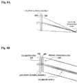
- an observer ( 40 )perceives the 3D image ( 10 ) because the observer's left eye ( 40 L) sees a different image than the observer's right eye ( 40 R).
- the display surface ( 21 )repeatedly projects about 30 to about 100 sets of ray trajectories (also referred to as “views”). The views can typically be seen by the observer ( 40 ) from a variety of viewpoints. For simplicity, FIG. 1 only depicts two views.
- FIG. 1depicts a display surface ( 21 ), which is defined for mathematical convenience, and is the surface from which rays emanate.
- FIG. 1also depicts a coordinate system, in which the x and y axes are coplanar to the display surface ( 21 ) and the z axis is normal to the display surface ( 21 ). In a horizontal-parallax-only mode, the x axis is parallel to the horizon and to the line connecting the observer's pupils.
- FIG. 2provides a top view of the situation depicted in FIG. 1 .
- a 3D scene ( 10 )is projected from the display surface ( 21 ) of the 3D display ( 20 ).
- An approximate measure of the horizontal viewing angle of the 3D image ( 10 )is a viewing zone ( 50 ).
- the horizontal angular extent of the horizontal viewing zone ( 50 )is defined as the radiative angular extent of a typical pixel ( 51 ) in a plane parallel to the xz plane.
- the 3D image ( 10 )is visible to the first observer ( 40 ) and a second observer ( 41 ) but not to a third observer ( 42 ).
- the 3D display ( 20 )provides a horizontal-parallax-only (HPO) display. It may instead be a full parallax display, in which case a vertical viewing zone could be defined and would have vertical parallax viewing qualities.
- HPOhorizontal-parallax-only
- FIG. 3illustrates a generalized process for computing and depicting 3D images ( 10 ) using a multi-view methodology.
- Projection of multi-view 3D imagestypically follows several steps.
- view-specific dataare acquired from a set of physical or computational (synthetic) “cameras.”
- a desired scene ( 22 ) of a flower in a flowerpotis illustrated.
- a series of computer-graphic cameras ( 23 )compute the appearance of the desired scene ( 22 ) from a multitude of positions along a horizontal track ( 24 ).
- about 30 to about 200 viewpointsare rendered and form a series of viewpoints ( 90 ).
- a leftmost image ( 100 ) and a rightmost image ( 199 )are depicted.
- Images between the leftmost image ( 100 ) and the rightmost image ( 199 )are represented by numbers between ( 100 ) and ( 199 ), wherein the reference numbers are representative of succession in the series of viewpoints ( 90 ). Playback or reconstruction of the desired scene occurs when the 3D display ( 20 ) projects rays of visible light to several locations.
- the left most image ( 100 )is projected by a ray bundle ( 100 ′)
- an intermediate depiction ( 110 )is projected by a ray bundle ( 110 ′).
- bundles ( 100 ′) and ( 110 ′)each meet at an apex, or pupil when an observer places his left eye ( 40 L) at the pupil formed by bundle ( 100 ′) and his right eye ( 40 R) at the pupil formed by bundle ( 110 ′), he sees images ( 100 ) and ( 110 ).
- the observerperceives a floating 3D image in the vicinity of the 3D display.
- FIG. 5illustrates an embodiment of a view-sequential 3D display ( 20 ).
- the embodiment depictedis disclosed in the pending U.S. patent application Ser. No., 11/146,749, filed Jun. 7, 2005, published Dec. 8, 2005 as publication no. 2005/0270645 A1, the disclosure of which is incorporated herein by reference in its entirety.
- a 3D projection system ( 200 )includes a first lenticular lens array ( 230 ) and a second lenticular lens array ( 235 ), at least one of which undergoes low-amplitude reciprocating translational movement to effect scanning. As depicted, the second lenticular lens array ( 235 ) is subject to the translational movement.
- a projector ( 210 )that projects the series of viewpoints ( 80 ) for a desired 3D image ( 10 ) is provided.
- the projector ( 210 )is typically controlled by standard electronics (aspects of which are depicted in FIG. 15 ).
- the projector ( 210 )is capable of frame rates in excess of 5,000 frames per second.
- One exemplary projector ( 210 )being a ferroelectric liquid crystal micro-display available from DisplayTech (Colorado, USA).
- An aperture ( 215 ), in the form of a column that is oriented parallel to the y-axis,is placed in front of the projector ( 210 ).
- a focusing optic ( 220 )re-images each viewpoint from the series of viewpoints ( 80 ) to the surface of a vertical diffuser ( 225 ) (or, optionally, to a Fresnel lens ( 222 )).
- verticalcorresponds to the orientation of the y-axis.
- Other componentsmay be included as deemed suitable (such as, for example, polarizing and “analyzing” components).
- the lightpasses through the first lenticular lens array ( 230 ) and subsequently the second lenticular lens array ( 235 ).
- a lens pitchis approximately 75 lenses per mm
- a focal lengthis approximately 300 microns for each of the first lenticular lens array ( 230 ) and the second lenticular lens array ( 235 ).
- a distance D between the lenticular lens arraysis approximately 600 microns (about 2 F), as measured from the “tops” of the lenticular lenses in each array. Scanning motion is performed by rapidly translating the second lenticular lens array ( 235 ) back and forth, with a travel path of about 300 microns.
- an illumination assemblysuch as a backlight, illuminates a transmissive spatial light modulator (SLM) ( 305 ) as the two-dimensional (2D ) image source.
- the lightpasses through an array of invisible microlouvers ( 310 ) that function like vertical blinds, a vertical diffuser ( 315 ), and a scanning assembly that includes a first lenticular lens array ( 320 ), and a second lenticular lens array ( 325 ).
- the second lenticular lens array ( 325 )is an oscillatory translating lenticular lens array. It should be noted that a variety of embodiments for the 2D image source may be realized.
- the fundamental image-generating componentis the spatial light modulator (SLM) ( 305 ).
- This SLM ( 305 )can be an emissive array such as an Organic LEDs (OLED) display panel, an array of micro-emitters such as lasers (e.g., vertical cavity surface emitting lasers, or VCSELs), a reflective display, a transreflective display, or other radiation-emitting module.
- OLEDOrganic LEDs
- micro-emitterse.g., vertical cavity surface emitting lasers, or VCSELs
- the image-generating componentis a reflective display, it may be illuminated using methods well-known to those skilled in the field of microdisplay system engineering (refer to FIG. 14 ).
- the spatial light modulator SLM ( 305 )is a non-limiting and merely exemplary embodiment. More specifically, one skilled in the art will recognize that the SLM ( 305 ) modulates incident light into patterns, while an emissive array may be used to directly create the patterns. In either case, and regardless of technique, the 2D image source provides for generation of a 2D pattern. Accordingly, the teachings herein are not limited to the apparatus disclosed herein in regard to the 2D image source and may include other devices as practicable.
- microlouvers ( 310 )are Vikuiti Light Control Films model numbers LCF-P 98-0440-2658-3 and ALCF-P 98-0440-4264-0, available from 3M Corporation (Minneapolis, Minn.).
- a variety of componentsmay be used as the 2D image source.
- a non-limiting exampleincludes an emissive array of Organic LEDs (OLEDs), which deliver thin, power efficient and bright displays with fast switching speeds).
- OLEDsOrganic LEDs
- Other non-limiting examplesinclude a spatial light modulator (e.g., a transmissive LCD panel, typically a transmissive ferroelectric LCD panel in combination with associated polarizing filters and analyzing filters).
- Exemplary OLED arraysinclude those available from Samsung Corporation, Emagin Corporation of Bellevue Wash., Kodak Corporation of Rochester, N.Y. and Universal Display Corporation of Ewing N.J.
- exemplary LCD-based light modulatorsinclude those available from Displaytech Ltd of Colorado and Fourth Dimension Displays (formerly CRL Opto), of Fife United Kingdom.
- LCD light based modulatorsmay further be used in conjunction with other illumination systems, such as color LED backlighting.
- Exemplary commercially available lenticular lens arraysinclude those available from Anteryon International B.V. and Microlens Technology, Inc.
- Exemplary commercially available components for use as optional diffusers and vertical diffusersinclude those available from Physical Optics Corp. and Dai Nippon Printing Co. Ltd of Japan.
- the 3D display ( 20 )employs a refresh rate where scanning (i.e., oscillatory translation of at least one of the lens arrays) would occur left-to-right or right-to-left at a frequency of about 60 Hz.
- scanningi.e., oscillatory translation of at least one of the lens arrays
- the 3D display ( 20 )uses a screen that is about 500 pixels by about 1,000 pixels, generates about 30 “views” per quasi-holographic image, and has total image depth of about 4′′ (10.16 mm, rounded to 10 mm) using 256 colors.
- Multi-color illuminationis provided by the OLED array if OLEDs are used for the 2D image source. If non-emissive modulators are used, the illumination will typically use off-the-shelf components. For example, near-eye displays might use switched LED illumination—cycling red, green, and blue LEDs to illuminate the 2D image source. That is, one skilled in the art will understand that the illumination assembly ( 300 ) may be arranged to provide a variety of predetermined wavelengths.
- the lenticular lens arrayswould typically have the same size and shape as the 2D image source.
- the lensletshave a focal length of about 800 microns and a lens pitch of about 300 microns.
- the lens pitchdoes not have to equal the source pixel pitch.
- the lens arrayis usually fabricated from a sheet of glass, and is therefore at least about 0.5 mm thick to about 1.0 mm thick. That is, the lens array is about as thick as its focal length, and usually abuts or nearly abuts the 2D image source.
- the lens arraystranslates about 125 microns back and forth. If the array moves too far, the first lens array will bleed unwanted light into an adjacent lens to a primary receiving lens on the second lens array, forming unwanted ghost images in the output. It should be that techniques are disclosed herein for controlling this problem.
- the barrier arraywill typically have a pitch equal or approximately equal to the 2D image source pixel pitch (i.e., the pitch in the SLM ( 305 )). That is, each pixel will be covered by a translucent window that limits the aperture of the pixel.
- This correlationserves two purposes. The correlation limits crosstalk between pixels thereby preventing ghost images. This has the benefit of increasing the contrast of the image and therefore improving the depth of the 3D image.
- aperturesare commonly used to prevent the effects of lens aberrations making 3D images crisper, at the expense of loss of brightness.
- a vertical diffuser ( 315 )is optional.
- An exemplary embodiment for a vertical diffuser ( 315 )includes those available from Physical Optics Corporation of Torrance, Calif. Typical embodiments for the vertical diffuser ( 315 ) have a horizontal beam spread of approx. 0.1 degrees and a vertical beam spread of 90 degrees.
- the vertical diffuser ( 315 )is placed as close as possible to the spatial light modulator ( 305 ) in order to minimize blur in the 3D image ( 10 ) associated with each pixel.
- first lenticular lens array ( 320 ) and second lenticular lens array ( 325 )are separated by approximately 2 F (1.6 mm).
- the “optical sandwich” that typically includes the components of FIG. 6can be made “thin.”
- the optical sandwich that provides for the 3D display ( 20 )is typically on the order of about 30 mm. Accordingly, the 3D display ( 20 ) is ideally suited for a variety of mobile applications.
- Translation of the lenticularcan be performed by a number of techniques, such as the use of a flexure stage.
- FIG. 6depicts an embodiment useful for a lenticular based system
- FIG. 7depicts another embodiment for implementing a hemispherical lens array or “fly's eye” system (refer to FIG. 11 ).
- the components of the 3D display ( 20 )are substantially close to each other or in contact with one another, and may, in some respects, be considered layers or substantially similar to layers. That is, substantial distances, such as distances between components for focusing or providing for other optical properties are generally not required. For example, the distance between the projector ( 210 ) and the scanning assembly is not called for. It should be noted that at least some distance between components of the optical sandwich may be required. For example, in the case of a translational lenticular lens array, at least some distance between a stationary lenticular lens array may be called for (e.g., to provide for unrestricted translation thereof). In this regard, the optical sandwich provides for the 3D display ( 20 ) having a minimized thickness.
- the 3D system ( 30 )may be constructed such that, for a given instant in time, the ray bundles ( 100 ′, 110 ′) do not converge (i.e., meet at an apex or pupil) but alternatively travel together in a mutually “collimated” (i.e., telecentric) manner.
- ray bundlesexit the display surface 21 having different trajectories, so that aggregated over the persistence of vision, pupils do form at the locations shown.
- FIG. 8A and FIG. 8Bcollectively referred to herein as FIG. 8 , depict aspects of image forming using the alternative techniques of a “convergence mode (i.e., the “pupil forming mode”) and a “telecentric mode,” repectively
- FIG. 8aspects of the optics for the convergence mode and the telecentric mode are depicted.
- a ray diagramis presented wherein the ray bundle converges at a location.
- FIG. 8Banother ray diagram is presented wherein a collimated beam is produced and the resulting beam “sweeps” the viewing zone 50 .
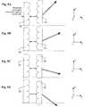
- FIG. 9A through FIG. 9Ddepicts aspects of the telecentric mode, wherein articulation of the second lenticular lens array ( 325 ) provides for redirecting the ray bundle (depicted as the grouped arrows).
- Various inputs to the first lenticular lens array ( 320 )may be used, including modulated illumination from the spatial light modulator ( 305 ), output from optional microlouvers ( 310 ), and others.
- FIG. 9generally depicts extrema for the ray bundle.
- the arrangement of the first lenticular lens array ( 320 ) and the second lenticular lens array ( 325 )provide for an f-stop of about 800 ⁇ m while the pitch is about 300 ⁇ m and the translational lens movement includes a horizontal translation of about 125 ⁇ m.
- oscillatory translation of the second lenticular lens array ( 325 )occurs in an X direction (as depicted).
- oscillatory translationoccurs in the X direction and a Y direction.
- translationmay occur in the Z direction (along a main optical path), such translation is not considered oscillatory and typically for purposes other than scanning.
- translation in the Z directionmay be undertaken for focusing of the 3D image ( 10 ) or improving aspects of the viewing zone ( 50 ).
- oscillatory translationgenerally occurs in at least one direction that is not along the main optical path.
- FIG. 10provides an illustration of the role of the vertical diffuser ( 315 ).
- a side view of the scanning assemblydepicts a vertical diffusion of the ray bundle when considered with reference to the observer 40 .
- first lenticular lens array ( 320 ) and the second lenticular lens array ( 325 )may be used to provide for a greater viewing zone 50 when compared to articulation of a single element.
- the articulation of the optical componentsare oscillatorily translatable. That is, whichever optical component is used for scanning will typically translate in a manner that is considered to be substantially equivalent to oscillation. Oscillatory translation may occur in any pattern deemed suitable. For example, in some embodiments, translation is merely horizontal. In other embodiments, translation follows a certain pattern. Reference may be had to FIG. 11 .
- FIG. 11aspects of another embodiment of a scanning assembly are shown.
- both the first lenticular lens array ( 320 ) and the second lenticular lens array ( 325 )are replaced with a first hemispherical lens array ( 420 ) and a second hemispherical lens array ( 425 ), respectively.
- the first hemispherical lens array ( 420 ) and the second hemispherical lens array ( 425 )forming a hemispherical scanning assembly ( 450 ).
- each “hemispherical lens array”is referred to as a “fly's eye” array.
- the hemispherical scanning assembly ( 450 )may be used advantageously to provide for full-parallax 3D displays (or equivalently two-axis beam steering).
- the first hemispherical lens array ( 420 )is in optical communication the second hemispherical lens array ( 425 ). Scanning can be achieved by moving the first hemispherical lens array ( 420 ), second hemispherical lens array ( 425 ), or both lens arrays ( 420 , 425 ).
- the oscillatory translating of the optical elementsmay follow any one or more of a horizontal path, a vertical path, a zig-zag path and a circuitous path (meaning any other type of path desired).
- FIG. 11depicts a zig-zag path for the oscillatory translation.
- a scanning path 475may include a vertical component (y axis) as well as the horizontal component (x axis).
- optical elements used in the scanning assemblyinclude, without limitation, lenticular elements, holographic optical elements (HOE), at least one irregular lens array, a “parallax” barrier array, an optical wedge and a prismatic optic as well as other radiation-steering component and a radiation-blocking component.
- HOEholographic optical elements
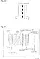
- FIG. 12the use of parallax barrier arrays as scanning elements is shown in FIG. 12 .
- a first barrier array ( 520 ) and a second barrier array ( 525 )are used in place of the first lenticular ( 320 ) and the second lenticular ( 325 ) for the scanning assembly.
- FIG. 12Athe ray bundle proceeds directly through the scanning assembly, while in FIG. 12B , the ray bundle is steered by translation of the second barrier array ( 525 ).
- FIG. 13depicts use of a single barrier array ( 520 ) in combination with the first lenticular array ( 320 ) and the second lenticular array ( 325 ).
- the barrier array ( 520 )typically includes an aperture associated with each lens that is designed to account for and minimize aberrations and crosstalk from adjacent pixels.
- FIG. 14depicts a further embodiment of the compact 3D display 20 .
- a beam splitter ( 345 )is incorporated.
- Use of the beam splitter ( 345 )provides for various advantages, such as the use of external illumination in combination with a reflective display.
- the use of external illuminationmay be useful for various purposes, such as to enhance brilliance in the image plane.
- FIG. 15depicts aspects of an exemplary embodiment of control electronics ( 261 ) for driving the compact 3D display ( 20 ).
- the control electronics ( 261 )typically include the scanning assembly ( 55 ), where at least one of the first lenticular array ( 320 ) and the second lenticular array ( 325 ) are coupled to a motive force ( 60 ) for driving translational movement.
- translationis controlled by a PID (proportional-integral-derivative) controller ( 80 ) that monitors the motion of the scaling assembly ( 55 ) using a diffractive motion encoder ( 81 ), and which, for example, drives a “voice coil” motor.
- PIDproportional-integral-derivative controller
- the details of the PID control loopwould be well-understood to those skilled in the field of servo control electronics and are therefore not discussed at length herein.
- a core rendering electronics subassembly ( 82 )assists in generating a sequence of 2-D perspective views projected by a fast SLM-based microdisplay ( 305 ).
- the core rendering electronics ( 82 )also receives velocity and position data from the PID controller ( 80 ) control loop. In this case, the core rendering electronics ( 82 ) are slaved to the scanning assembly ( 55 ). Alternatively, the core rendering electronics ( 82 ) can act as master to the scanning assembly ( 55 ).
- the scanning assembly ( 55 )undergoes time-varying optical properties, and that the SLM ( 305 ) is located adjacent to the scanning assembly ( 55 ) to shine light on or through the scanning assembly ( 55 ) in order to produce the 3D image.
- the scanning assembly ( 55 )may spend a significant interval of time at the extremes of a scan path. It is understood that, at least in some instances that if light passed through the screen during those intervals, the light would be too bright to be displayed properly. Therefore, “blank” (black) data are typically loaded into the 2D image source for the extreme views. As an illustration, for a sweep path having fifty positions, a forty-ninth clock is used to trigger a pre-load of a black screen for those views.
- references to the term “lenticular”should be interpreted to include other methods for using spatial multiplexing to encode two or more views of a 3D image ( 10 ) into a single 2D field of pixels.
- These “panoramagrams” or “parallax displays”can use many optical devices to perform demultiplexing, such as lenticular sheets, parallax barriers, fly's-eye lens arrays, or holographic optical elements.
- the teachings hereingenerally provide for employing lenticular arrays and other optical arrays for a time-multiplexed manner rather than or in addition to a spatially-multiplexed manner.
- FIG. 16An exemplary method for providing the 3D image ( 10 ) is depicted in FIG. 16 .
- Providing the 3D image ( 500 )typically calls for selecting the 3D system ( 501 ), providing a series of viewpoints ( 502 ) to the 3D system ( 30 ), controlling the 2D image source ( 503 ), controlling the scanning assembly ( 504 ) for simultaneously displaying the series of viewpoints ( 505 ), thus providing the 3D image.
- Selecting the 3D system ( 501 )calls for selecting the 3D system ( 30 ) that includes appropriate components and features for producing the desired type of 3D image ( 10 ). For example, size, color, resolution, scan rate and other features may be considered when selecting the 3D system ( 501 ).
- Providing the series of viewpoints ( 502 )typically calls for assembling a series of viewpoints ( 90 ) produced in a manner that is generally consistent with the manner discussed above with reference to FIG. 3 , or may involve some equivalent thereto.
- the series of viewpoints ( 90 )is typically provided by electronics as depicted in FIG. 15 , or by some equivalent thereto.
- Controlling the 2D image source ( 503 ) and controlling the scanning assembly ( 504 )similarly call for using the control electronics ( 261 ) to generate at least one 2D image in the spatial light modulator ( 305 ) and to drive the oscillatory translations of the optics.
- the scan rateis fast enough to provide an illusion of the 3D image ( 10 ) to the unaided human eye. It should be recognized that observation of the 3D image ( 10 ) with other devices (such as a video camera) may alter or destroy the perception of a continuous display.
- the oscillatory motion of at least one of the optical elementsincludes an oscillation of a high enough frequency that incremental display of each viewpoint ( 90 ) from the series of viewpoints is substantially completed within an integration period for the human eye.
- controlling the 2D image source ( 503 ) and controlling the scanning assembly ( 504 )calls for operating the 3D system ( 30 ) in the pupil-forming mode.
- controlling the 2D image source ( 503 ) and controlling the scanning assembly ( 504 )calls for operating the 3D system ( 30 ) in the telecentric mode.
- Other embodimentscontemplate operation of or accounting for certain additional components such as the microlouvers ( 310 ), the vertical diffuser ( 315 ) and other such aspects, some of which are described herein.
Landscapes
- Physics & Mathematics (AREA)
- General Physics & Mathematics (AREA)
- Optics & Photonics (AREA)
- Engineering & Computer Science (AREA)
- Multimedia (AREA)
- Signal Processing (AREA)
- Testing, Inspecting, Measuring Of Stereoscopic Televisions And Televisions (AREA)
Abstract
Description
Claims (35)
Priority Applications (3)
| Application Number | Priority Date | Filing Date | Title |
|---|---|---|---|
| US11/380,296US8675125B2 (en) | 2005-04-27 | 2006-04-26 | Minimized-thickness angular scanner of electromagnetic radiation |
| US14/162,401US9182604B2 (en) | 2005-04-27 | 2014-01-23 | Minimized-thickness angular scanner of electromagnetic radiation |
| US14/931,174US9958694B2 (en) | 2005-04-27 | 2015-11-03 | Minimized-thickness angular scanner of electromagnetic radiation |
Applications Claiming Priority (2)
| Application Number | Priority Date | Filing Date | Title |
|---|---|---|---|
| US67516505P | 2005-04-27 | 2005-04-27 | |
| US11/380,296US8675125B2 (en) | 2005-04-27 | 2006-04-26 | Minimized-thickness angular scanner of electromagnetic radiation |
Related Child Applications (1)
| Application Number | Title | Priority Date | Filing Date |
|---|---|---|---|
| US14/162,401ContinuationUS9182604B2 (en) | 2005-04-27 | 2014-01-23 | Minimized-thickness angular scanner of electromagnetic radiation |
Publications (2)
| Publication Number | Publication Date |
|---|---|
| US20060244918A1 US20060244918A1 (en) | 2006-11-02 |
| US8675125B2true US8675125B2 (en) | 2014-03-18 |
Family
ID=37234096
Family Applications (3)
| Application Number | Title | Priority Date | Filing Date |
|---|---|---|---|
| US11/380,296Active2030-04-27US8675125B2 (en) | 2005-04-27 | 2006-04-26 | Minimized-thickness angular scanner of electromagnetic radiation |
| US14/162,401Expired - Fee RelatedUS9182604B2 (en) | 2005-04-27 | 2014-01-23 | Minimized-thickness angular scanner of electromagnetic radiation |
| US14/931,174Active2026-11-18US9958694B2 (en) | 2005-04-27 | 2015-11-03 | Minimized-thickness angular scanner of electromagnetic radiation |
Family Applications After (2)
| Application Number | Title | Priority Date | Filing Date |
|---|---|---|---|
| US14/162,401Expired - Fee RelatedUS9182604B2 (en) | 2005-04-27 | 2014-01-23 | Minimized-thickness angular scanner of electromagnetic radiation |
| US14/931,174Active2026-11-18US9958694B2 (en) | 2005-04-27 | 2015-11-03 | Minimized-thickness angular scanner of electromagnetic radiation |
Country Status (1)
| Country | Link |
|---|---|
| US (3) | US8675125B2 (en) |
Cited By (14)
| Publication number | Priority date | Publication date | Assignee | Title |
|---|---|---|---|---|
| US9343489B2 (en) | 2011-05-12 | 2016-05-17 | DePuy Synthes Products, Inc. | Image sensor for endoscopic use |
| US9462234B2 (en) | 2012-07-26 | 2016-10-04 | DePuy Synthes Products, Inc. | Camera system with minimal area monolithic CMOS image sensor |
| US9516239B2 (en) | 2012-07-26 | 2016-12-06 | DePuy Synthes Products, Inc. | YCBCR pulsed illumination scheme in a light deficient environment |
| US9641815B2 (en) | 2013-03-15 | 2017-05-02 | DePuy Synthes Products, Inc. | Super resolution and color motion artifact correction in a pulsed color imaging system |
| US9777913B2 (en) | 2013-03-15 | 2017-10-03 | DePuy Synthes Products, Inc. | Controlling the integral light energy of a laser pulse |
| US9967546B2 (en) | 2013-10-29 | 2018-05-08 | Vefxi Corporation | Method and apparatus for converting 2D-images and videos to 3D for consumer, commercial and professional applications |
| US10084944B2 (en) | 2014-03-21 | 2018-09-25 | DePuy Synthes Products, Inc. | Card edge connector for an imaging sensor |
| US10158847B2 (en) | 2014-06-19 | 2018-12-18 | Vefxi Corporation | Real—time stereo 3D and autostereoscopic 3D video and image editing |
| US10250864B2 (en) | 2013-10-30 | 2019-04-02 | Vefxi Corporation | Method and apparatus for generating enhanced 3D-effects for real-time and offline applications |
| US10251530B2 (en) | 2013-03-15 | 2019-04-09 | DePuy Synthes Products, Inc. | Scope sensing in a light controlled environment |
| US10517469B2 (en) | 2013-03-15 | 2019-12-31 | DePuy Synthes Products, Inc. | Image sensor synchronization without input clock and data transmission clock |
| US10568496B2 (en) | 2012-07-26 | 2020-02-25 | DePuy Synthes Products, Inc. | Continuous video in a light deficient environment |
| US10750933B2 (en) | 2013-03-15 | 2020-08-25 | DePuy Synthes Products, Inc. | Minimize image sensor I/O and conductor counts in endoscope applications |
| US20210302756A1 (en)* | 2018-08-29 | 2021-09-30 | Pcms Holdings, Inc. | Optical method and system for light field displays based on mosaic periodic layer |
Families Citing this family (67)
| Publication number | Priority date | Publication date | Assignee | Title |
|---|---|---|---|---|
| KR101255209B1 (en)* | 2006-05-04 | 2013-04-23 | 삼성전자주식회사 | Hihg resolution autostereoscopic display apparatus with lnterlaced image |
| US20080194930A1 (en)* | 2007-02-09 | 2008-08-14 | Harris Melvyn L | Infrared-visible needle |
| US8491121B2 (en)* | 2007-10-09 | 2013-07-23 | Elbit Systems Of America, Llc | Pupil scan apparatus |
| US7957061B1 (en) | 2008-01-16 | 2011-06-07 | Holovisions LLC | Device with array of tilting microcolumns to display three-dimensional images |
| JP4404146B2 (en)* | 2008-01-17 | 2010-01-27 | パナソニック株式会社 | Projection type 3D image reproduction device |
| KR101658793B1 (en)* | 2008-10-09 | 2016-09-23 | 삼성전자주식회사 | Apparatus and method for 2d and 3d image switchable display |
| US7889425B1 (en) | 2008-12-30 | 2011-02-15 | Holovisions LLC | Device with array of spinning microlenses to display three-dimensional images |
| US7978407B1 (en) | 2009-06-27 | 2011-07-12 | Holovisions LLC | Holovision (TM) 3D imaging with rotating light-emitting members |
| US8854531B2 (en)* | 2009-12-31 | 2014-10-07 | Broadcom Corporation | Multiple remote controllers that each simultaneously controls a different visual presentation of a 2D/3D display |
| US8823782B2 (en) | 2009-12-31 | 2014-09-02 | Broadcom Corporation | Remote control with integrated position, viewer identification and optical and audio test |
| US20110157322A1 (en)* | 2009-12-31 | 2011-06-30 | Broadcom Corporation | Controlling a pixel array to support an adaptable light manipulator |
| US9247286B2 (en)* | 2009-12-31 | 2016-01-26 | Broadcom Corporation | Frame formatting supporting mixed two and three dimensional video data communication |
| TW201128227A (en)* | 2010-02-12 | 2011-08-16 | Young Optics Inc | Optical projection system and method for reducing ghost image generated therein |
| US8587498B2 (en) | 2010-03-01 | 2013-11-19 | Holovisions LLC | 3D image display with binocular disparity and motion parallax |
| US8502816B2 (en)* | 2010-12-02 | 2013-08-06 | Microsoft Corporation | Tabletop display providing multiple views to users |
| US9291830B2 (en) | 2011-02-27 | 2016-03-22 | Dolby Laboratories Licensing Corporation | Multiview projector system |
| US9813695B2 (en) | 2011-11-09 | 2017-11-07 | Koninklijke Philips N.V. | Display device with free focus capability |
| WO2013105000A2 (en)* | 2012-01-15 | 2013-07-18 | Zecotek Display System Ltd. Pte. | Optical imaging system and 3d display apparatus |
| US9235057B2 (en) | 2012-05-18 | 2016-01-12 | Reald Inc. | Polarization recovery in a directional display device |
| EP2850488A4 (en) | 2012-05-18 | 2016-03-02 | Reald Inc | Directional backlight |
| KR102099590B1 (en) | 2012-05-18 | 2020-04-10 | 리얼디 스파크, 엘엘씨 | Controlling light sources of a directional backlight |
| US9678267B2 (en) | 2012-05-18 | 2017-06-13 | Reald Spark, Llc | Wide angle imaging directional backlights |
| US9188731B2 (en) | 2012-05-18 | 2015-11-17 | Reald Inc. | Directional backlight |
| WO2014018269A1 (en)* | 2012-07-23 | 2014-01-30 | Reald Inc. | Observer tracking autostereoscopic display |
| TWI459037B (en)* | 2012-09-11 | 2014-11-01 | Delta Electronics Inc | System and method for time-multiplexed autostereoscopic display |
| CN103676448B (en)* | 2012-09-11 | 2016-05-25 | 台达电子工业股份有限公司 | Time multiplexing automatic stereo display system and method |
| TWI472803B (en)* | 2012-12-28 | 2015-02-11 | Delta Electronics Inc | Virtual image displaying system |
| CN111487707A (en) | 2013-02-22 | 2020-08-04 | 瑞尔D斯帕克有限责任公司 | directional backlight |
| WO2014144989A1 (en) | 2013-03-15 | 2014-09-18 | Ostendo Technologies, Inc. | 3d light field displays and methods with improved viewing angle depth and resolution |
| KR102254799B1 (en) | 2013-06-17 | 2021-05-24 | 리얼디 스파크, 엘엘씨 | Controlling light sources of a directional backlight |
| US20150042640A1 (en)* | 2013-08-07 | 2015-02-12 | Cherif Atia Algreatly | Floating 3d image in midair |
| US9823482B2 (en)* | 2013-08-19 | 2017-11-21 | Universal Display Corporation | Autostereoscopic displays |
| KR102366346B1 (en) | 2013-10-14 | 2022-02-23 | 리얼디 스파크, 엘엘씨 | Light input for directional backlight |
| EP3058562A4 (en) | 2013-10-14 | 2017-07-26 | RealD Spark, LLC | Control of directional display |
| EP2957948B1 (en) | 2014-06-16 | 2017-08-02 | Juan Dominguez-Montes | System for reproducing stereoscopic images by projection |
| EP3161550A4 (en) | 2014-06-26 | 2018-04-18 | RealD Spark, LLC | Directional privacy display |
| WO2016057690A1 (en) | 2014-10-08 | 2016-04-14 | Reald Inc. | Directional backlight |
| US10356383B2 (en) | 2014-12-24 | 2019-07-16 | Reald Spark, Llc | Adjustment of perceived roundness in stereoscopic image of a head |
| CN104539935B (en)* | 2015-01-19 | 2017-05-31 | 北京京东方多媒体科技有限公司 | The adjusting method and adjusting means of brightness of image, display device |
| CN105868084A (en)* | 2015-01-23 | 2016-08-17 | 富泰华工业(深圳)有限公司 | Prompt system and method |
| RU2596062C1 (en) | 2015-03-20 | 2016-08-27 | Автономная Некоммерческая Образовательная Организация Высшего Профессионального Образования "Сколковский Институт Науки И Технологий" | Method for correction of eye image using machine learning and method of machine learning |
| WO2016168345A1 (en) | 2015-04-13 | 2016-10-20 | Reald Inc. | Wide angle imaging directional backlights |
| CN107850804B (en) | 2015-05-27 | 2021-06-11 | 瑞尔D斯帕克有限责任公司 | Wide-angle imaging directional backlight |
| CN104880831A (en)* | 2015-06-19 | 2015-09-02 | 京东方科技集团股份有限公司 | Three-dimensional display device and control method of three-dimensional display device |
| US10475418B2 (en) | 2015-10-26 | 2019-11-12 | Reald Spark, Llc | Intelligent privacy system, apparatus, and method thereof |
| WO2017083526A1 (en) | 2015-11-10 | 2017-05-18 | Reald Inc. | Distortion matching polarization conversion systems and methods thereof |
| EP3374692B1 (en) | 2015-11-13 | 2021-02-24 | RealD Spark, LLC | Wide angle imaging directional backlights |
| WO2017083583A1 (en) | 2015-11-13 | 2017-05-18 | Reald Spark, Llc | Surface features for imaging directional backlights |
| CN114143495B (en) | 2016-01-05 | 2025-07-15 | 瑞尔D斯帕克有限责任公司 | Gaze Correction for Multi-View Images |
| CN105676466B (en)* | 2016-01-07 | 2017-12-15 | 京东方科技集团股份有限公司 | A kind of 3D display panel, display device |
| EP3458897B1 (en) | 2016-05-19 | 2025-04-02 | RealD Spark, LLC | Wide angle imaging directional backlights |
| US10425635B2 (en) | 2016-05-23 | 2019-09-24 | Reald Spark, Llc | Wide angle imaging directional backlights |
| WO2018129059A1 (en) | 2017-01-04 | 2018-07-12 | Reald Spark, Llc | Optical stack for imaging directional backlights |
| EP3607387A4 (en) | 2017-04-03 | 2020-11-25 | RealD Spark, LLC | Segmented imaging directional backlights |
| GB2567408B (en) | 2017-08-02 | 2020-12-02 | Dualitas Ltd | Holographic projector |
| CN111183405A (en) | 2017-08-08 | 2020-05-19 | 瑞尔D斯帕克有限责任公司 | Adjust the digital representation of the head area |
| CN108347596B (en)* | 2017-11-02 | 2020-01-31 | 广东康云多维视觉智能科技有限公司 | A feedback-based laser-guided scanning system and method |
| WO2019090246A1 (en) | 2017-11-06 | 2019-05-09 | Reald Spark, Llc | Privacy display apparatus |
| KR102759510B1 (en) | 2018-01-25 | 2025-02-04 | 리얼디 스파크, 엘엘씨 | Touchscreen for privacy display |
| US10298921B1 (en) | 2018-02-27 | 2019-05-21 | Looking Glass Factory, Inc. | Superstereoscopic display with enhanced off-angle separation |
| GB2582965B (en) | 2019-04-11 | 2021-09-15 | Dualitas Ltd | A diffuser assembly |
| EP3953748A1 (en)* | 2019-04-12 | 2022-02-16 | PCMS Holdings, Inc. | Optical method and system for light field displays having light-steering layers and periodic optical layer |
| WO2021237065A1 (en) | 2020-05-21 | 2021-11-25 | Looking Glass Factory, Inc. | System and method for holographic image display |
| WO2021243037A1 (en)* | 2020-05-27 | 2021-12-02 | Looking Glass Factory, Inc. | System and method for holographic displays |
| CN116194812A (en) | 2020-09-16 | 2023-05-30 | 瑞尔D斯帕克有限责任公司 | Vehicle Exterior Lighting |
| US11966049B2 (en) | 2022-08-02 | 2024-04-23 | Reald Spark, Llc | Pupil tracking near-eye display |
| WO2024035796A1 (en) | 2022-08-11 | 2024-02-15 | Reald Spark, Llc | Anamorphic directional illumination device |
Citations (28)
| Publication number | Priority date | Publication date | Assignee | Title |
|---|---|---|---|---|
| US3125927A (en)* | 1964-03-24 | Projection screen | ||
| US3881810A (en) | 1973-11-12 | 1975-05-06 | Sanders Associates Inc | Large field light modulator |
| US4070089A (en) | 1976-07-01 | 1978-01-24 | Xerox Corporation | Two dimensional laser scanner with movable cylinder lens |
| US4078854A (en) | 1971-10-05 | 1978-03-14 | Canon Kabushiki Kaisha | Stereo imaging system |
| US4107712A (en) | 1974-12-25 | 1978-08-15 | Law Chi Y | Camera for taking three dimensional photographs having screen moving means |
| US4317618A (en) | 1979-05-02 | 1982-03-02 | Fuji Photo Film Co., Ltd. | Vibrating screen for image projection |
| US4390239A (en) | 1980-05-14 | 1983-06-28 | Johannes Heidenhain Gmbh | Projection screen |
| US4456783A (en) | 1982-11-23 | 1984-06-26 | Polaroid Corporation | Multielement optical panel |
| US4468115A (en) | 1982-05-26 | 1984-08-28 | Nimslo International Limited | Travelling lamp house for 3-D photographic printer |
| US4502751A (en) | 1983-02-15 | 1985-03-05 | Rockwell International Corporation | Linear optical scanner |
| US4698498A (en) | 1986-04-28 | 1987-10-06 | Robot Defense Systems, Inc. | Three-dimensional laser imaging transmitter/receiver |
| US4853769A (en) | 1987-06-16 | 1989-08-01 | Massachusetts Institute Of Technology | Time multiplexed auto-stereoscopic three-dimensional imaging system |
| US5392140A (en) | 1992-05-15 | 1995-02-21 | Sharp Kabushiki Kaisha | Optical device with two lens arrays with the second array pitch an integral multiple of the first array pitch |
| US5465175A (en)* | 1992-11-11 | 1995-11-07 | Sharp Kabushiki Kaisha | Autostereoscopic display device |
| US5546120A (en) | 1992-11-05 | 1996-08-13 | Perceptual Images | Autostereoscopic display system using shutter and back-to-back lenticular screen |
| US5930037A (en) | 1996-04-30 | 1999-07-27 | Nec Corporation | Stereoscopic display apparatus which prevents inverse stereoscopic vision |
| US6008484A (en) | 1996-09-27 | 1999-12-28 | Sharp Kabushiki Kaisha | Observer tracking directional display and observer tracking illumination system |
| US6061179A (en)* | 1996-01-23 | 2000-05-09 | Canon Kabushiki Kaisha | Stereoscopic image display apparatus with two-/three-dimensional image display switching function |
| US6061489A (en) | 1994-10-12 | 2000-05-09 | Sharp Kabushiki Kaisha | Light source and display |
| US6487020B1 (en)* | 1998-09-24 | 2002-11-26 | Actuality Systems, Inc | Volumetric three-dimensional display architecture |
| US6624919B2 (en) | 1999-03-31 | 2003-09-23 | Koninklijke Philips Electronics N.V. | Light scanner with cylindrical lenses |
| US20030210461A1 (en)* | 2002-03-15 | 2003-11-13 | Koji Ashizaki | Image processing apparatus and method, printed matter production apparatus and method, and printed matter production system |
| US6806851B2 (en) | 2000-12-08 | 2004-10-19 | The University Of Tokyo | Image displaying method and an image display |
| US20050146787A1 (en)* | 1999-12-08 | 2005-07-07 | Neurok Llc | Composite dual LCD panel display suitable for three dimensional imaging |
| US20050248972A1 (en)* | 2002-06-13 | 2005-11-10 | Tetsujiro Kondo | Imaging device and imaging method, and display unit and display method |
| US7050020B2 (en)* | 2002-08-27 | 2006-05-23 | Nec Corporation | 3D image/2D image switching display apparatus and portable terminal device |
| US20060202910A1 (en)* | 2005-03-03 | 2006-09-14 | Samsung Electronics Co., Ltd. | 2D/3D switchable display |
| US7277226B2 (en) | 2004-01-16 | 2007-10-02 | Actuality Systems, Inc. | Radial multiview three-dimensional displays |
Family Cites Families (3)
| Publication number | Priority date | Publication date | Assignee | Title |
|---|---|---|---|---|
| US2012995A (en) | 1929-02-09 | 1935-09-03 | Bell Telephone Labor Inc | Stereoscopic motion picture |
| GB2317291A (en) | 1996-09-12 | 1998-03-18 | Sharp Kk | Observer tracking directional display |
| US7699472B2 (en)* | 2004-09-24 | 2010-04-20 | Samsung Electronics Co., Ltd. | Multi-view autostereoscopic projection system using single projection lens unit |
- 2006
- 2006-04-26USUS11/380,296patent/US8675125B2/enactiveActive
- 2014
- 2014-01-23USUS14/162,401patent/US9182604B2/ennot_activeExpired - Fee Related
- 2015
- 2015-11-03USUS14/931,174patent/US9958694B2/enactiveActive
Patent Citations (28)
| Publication number | Priority date | Publication date | Assignee | Title |
|---|---|---|---|---|
| US3125927A (en)* | 1964-03-24 | Projection screen | ||
| US4078854A (en) | 1971-10-05 | 1978-03-14 | Canon Kabushiki Kaisha | Stereo imaging system |
| US3881810A (en) | 1973-11-12 | 1975-05-06 | Sanders Associates Inc | Large field light modulator |
| US4107712A (en) | 1974-12-25 | 1978-08-15 | Law Chi Y | Camera for taking three dimensional photographs having screen moving means |
| US4070089A (en) | 1976-07-01 | 1978-01-24 | Xerox Corporation | Two dimensional laser scanner with movable cylinder lens |
| US4317618A (en) | 1979-05-02 | 1982-03-02 | Fuji Photo Film Co., Ltd. | Vibrating screen for image projection |
| US4390239A (en) | 1980-05-14 | 1983-06-28 | Johannes Heidenhain Gmbh | Projection screen |
| US4468115A (en) | 1982-05-26 | 1984-08-28 | Nimslo International Limited | Travelling lamp house for 3-D photographic printer |
| US4456783A (en) | 1982-11-23 | 1984-06-26 | Polaroid Corporation | Multielement optical panel |
| US4502751A (en) | 1983-02-15 | 1985-03-05 | Rockwell International Corporation | Linear optical scanner |
| US4698498A (en) | 1986-04-28 | 1987-10-06 | Robot Defense Systems, Inc. | Three-dimensional laser imaging transmitter/receiver |
| US4853769A (en) | 1987-06-16 | 1989-08-01 | Massachusetts Institute Of Technology | Time multiplexed auto-stereoscopic three-dimensional imaging system |
| US5392140A (en) | 1992-05-15 | 1995-02-21 | Sharp Kabushiki Kaisha | Optical device with two lens arrays with the second array pitch an integral multiple of the first array pitch |
| US5546120A (en) | 1992-11-05 | 1996-08-13 | Perceptual Images | Autostereoscopic display system using shutter and back-to-back lenticular screen |
| US5465175A (en)* | 1992-11-11 | 1995-11-07 | Sharp Kabushiki Kaisha | Autostereoscopic display device |
| US6061489A (en) | 1994-10-12 | 2000-05-09 | Sharp Kabushiki Kaisha | Light source and display |
| US6061179A (en)* | 1996-01-23 | 2000-05-09 | Canon Kabushiki Kaisha | Stereoscopic image display apparatus with two-/three-dimensional image display switching function |
| US5930037A (en) | 1996-04-30 | 1999-07-27 | Nec Corporation | Stereoscopic display apparatus which prevents inverse stereoscopic vision |
| US6008484A (en) | 1996-09-27 | 1999-12-28 | Sharp Kabushiki Kaisha | Observer tracking directional display and observer tracking illumination system |
| US6487020B1 (en)* | 1998-09-24 | 2002-11-26 | Actuality Systems, Inc | Volumetric three-dimensional display architecture |
| US6624919B2 (en) | 1999-03-31 | 2003-09-23 | Koninklijke Philips Electronics N.V. | Light scanner with cylindrical lenses |
| US20050146787A1 (en)* | 1999-12-08 | 2005-07-07 | Neurok Llc | Composite dual LCD panel display suitable for three dimensional imaging |
| US6806851B2 (en) | 2000-12-08 | 2004-10-19 | The University Of Tokyo | Image displaying method and an image display |
| US20030210461A1 (en)* | 2002-03-15 | 2003-11-13 | Koji Ashizaki | Image processing apparatus and method, printed matter production apparatus and method, and printed matter production system |
| US20050248972A1 (en)* | 2002-06-13 | 2005-11-10 | Tetsujiro Kondo | Imaging device and imaging method, and display unit and display method |
| US7050020B2 (en)* | 2002-08-27 | 2006-05-23 | Nec Corporation | 3D image/2D image switching display apparatus and portable terminal device |
| US7277226B2 (en) | 2004-01-16 | 2007-10-02 | Actuality Systems, Inc. | Radial multiview three-dimensional displays |
| US20060202910A1 (en)* | 2005-03-03 | 2006-09-14 | Samsung Electronics Co., Ltd. | 2D/3D switchable display |
Non-Patent Citations (18)
| Title |
|---|
| Akihito Nakai, "A Stereoscopic Display with a Vibrating Microlens Array". Department of Informatics, Faculty of Engineering, The University of Tokyo. pp. 524-527. |
| Byoungho Lee, "Theoretical analysis for three-dimensional integral imaging systems with double devices". Applied Optics/ vol. 41, No. 23/ Aug. 10, 2002. pp. 4856-4865. |
| Edward A. Watson. "Analysis of beam steering with decentered microlens arrays". Optical Engineering. 32 Nov. 1993, No. 11, Bellingham, WA, US. pp. 2665-2670. |
| Edward A. Watson. Implementing Optical Phased Array Beam Steering with Cascaded Microlens Arrays. 2002. pp. 1429-1436. |
| H. Hoshino, "Analysis of resolution limitation of integral photography". vol. 15, No. 8/Aug. 1998/ J.Opt. Soc. Am. A. pp. 2059-2065. |
| IBM Technical Disclosure Bulletin. "Autostereoscopic 3-D Image Display Device". vol. 37 No. 12 Dec. 1994. pp. 177-178. |
| International Search Report for PCT/US2005/020441. Mailed Nov. 8, 2005. |
| Jesse B. Eichenlaub. A multiperspective look around autostereoscopic projection display using an ICFLCD. Part of the IS&T/SPIE Conference on Steroscopic Displays and Applicatoins X. San Jose, California. Jan. 1999. SPIE vol. 3639. pp. 110-121. |
| M C Hutley, "The use of microlenses for making spatially variant optical interconnections" Pure Appl. Ot. 1 (1992) 337-346. Printed in the UK. |
| M. Edward Motamedi. "Miniaturized micro-optical scanners". Optical Engineering. 33Nov. 1994, No. 11, Bellingham, WA, US. pp. 3616-3623. |
| Michael Halle. "Autostereoscopic Displays and Computer Graphics". Computer Graphics. May 1997. pp. 58-62. |
| Motoaki Kawazu. "Application of gradient-index fiber arrays to copying machines". Apr. 1, 1980/ vol. 19, No. 7/ Applied Optics. pp. 1105-1112. |
| Neil Davies. "Three-dimensional imaging systems: a new development". Applied Optics/ vol. 27, No. 21/ Nov. 1, 1988. pp. 4520-4528. |
| R.H. Anderson. "Close-up imaging of documents and displays with lens arrays". Feb. 15, 1979/ vol. 18, No. 4/ Applied Optics. pp. 477-484. |
| Shaoulov. "Compact microlenslet-array-based magnifier". Apr. 1, 2004/ vol. 29., No. 7/ Optics Letters. pp. 709-711. |
| Siegmund Pastoor. "An Experimental Multimedia System Allowing 3-D Visualization and Eye-Controlled Interaction without User-Worn Devices". IEEE Transactions on Multimedia, vol. 1, No. 1, Mar. 1999. pp. 41-52. |
| Vesselin Shaoulov. "Design and assessment of microlenslet-array relay optics". Applied Optics/vol. 42, No. 34/ Dec. 1, 2003. pp. 6838-6845. |
| Vikuiti Advanced Light Control Film (ALCF-P). 3M Innovation. 3 pages. |
Cited By (55)
| Publication number | Priority date | Publication date | Assignee | Title |
|---|---|---|---|---|
| US9907459B2 (en) | 2011-05-12 | 2018-03-06 | DePuy Synthes Products, Inc. | Image sensor with tolerance optimizing interconnects |
| US11848337B2 (en) | 2011-05-12 | 2023-12-19 | DePuy Synthes Products, Inc. | Image sensor |
| US10709319B2 (en) | 2011-05-12 | 2020-07-14 | DePuy Synthes Products, Inc. | System and method for sub-column parallel digitizers for hybrid stacked image sensor using vertical interconnects |
| US9622650B2 (en) | 2011-05-12 | 2017-04-18 | DePuy Synthes Products, Inc. | System and method for sub-column parallel digitizers for hybrid stacked image sensor using vertical interconnects |
| US12100716B2 (en) | 2011-05-12 | 2024-09-24 | DePuy Synthes Products, Inc. | Image sensor with tolerance optimizing interconnects |
| US10537234B2 (en) | 2011-05-12 | 2020-01-21 | DePuy Synthes Products, Inc. | Image sensor with tolerance optimizing interconnects |
| US10863894B2 (en) | 2011-05-12 | 2020-12-15 | DePuy Synthes Products, Inc. | System and method for sub-column parallel digitizers for hybrid stacked image sensor using vertical interconnects |
| US9763566B2 (en) | 2011-05-12 | 2017-09-19 | DePuy Synthes Products, Inc. | Pixel array area optimization using stacking scheme for hybrid image sensor with minimal vertical interconnects |
| US11179029B2 (en) | 2011-05-12 | 2021-11-23 | DePuy Synthes Products, Inc. | Image sensor with tolerance optimizing interconnects |
| US11026565B2 (en) | 2011-05-12 | 2021-06-08 | DePuy Synthes Products, Inc. | Image sensor for endoscopic use |
| US9980633B2 (en) | 2011-05-12 | 2018-05-29 | DePuy Synthes Products, Inc. | Image sensor for endoscopic use |
| US11109750B2 (en) | 2011-05-12 | 2021-09-07 | DePuy Synthes Products, Inc. | Pixel array area optimization using stacking scheme for hybrid image sensor with minimal vertical interconnects |
| US10517471B2 (en) | 2011-05-12 | 2019-12-31 | DePuy Synthes Products, Inc. | Pixel array area optimization using stacking scheme for hybrid image sensor with minimal vertical interconnects |
| US11682682B2 (en) | 2011-05-12 | 2023-06-20 | DePuy Synthes Products, Inc. | Pixel array area optimization using stacking scheme for hybrid image sensor with minimal vertical interconnects |
| US11432715B2 (en) | 2011-05-12 | 2022-09-06 | DePuy Synthes Products, Inc. | System and method for sub-column parallel digitizers for hybrid stacked image sensor using vertical interconnects |
| US9343489B2 (en) | 2011-05-12 | 2016-05-17 | DePuy Synthes Products, Inc. | Image sensor for endoscopic use |
| US11863878B2 (en) | 2012-07-26 | 2024-01-02 | DePuy Synthes Products, Inc. | YCBCR pulsed illumination scheme in a light deficient environment |
| US10277875B2 (en) | 2012-07-26 | 2019-04-30 | DePuy Synthes Products, Inc. | YCBCR pulsed illumination scheme in a light deficient environment |
| US11766175B2 (en) | 2012-07-26 | 2023-09-26 | DePuy Synthes Products, Inc. | Camera system with minimal area monolithic CMOS image sensor |
| US10075626B2 (en) | 2012-07-26 | 2018-09-11 | DePuy Synthes Products, Inc. | Camera system with minimal area monolithic CMOS image sensor |
| US9762879B2 (en) | 2012-07-26 | 2017-09-12 | DePuy Synthes Products, Inc. | YCbCr pulsed illumination scheme in a light deficient environment |
| US10568496B2 (en) | 2012-07-26 | 2020-02-25 | DePuy Synthes Products, Inc. | Continuous video in a light deficient environment |
| US11083367B2 (en) | 2012-07-26 | 2021-08-10 | DePuy Synthes Products, Inc. | Continuous video in a light deficient environment |
| US10701254B2 (en) | 2012-07-26 | 2020-06-30 | DePuy Synthes Products, Inc. | Camera system with minimal area monolithic CMOS image sensor |
| US9516239B2 (en) | 2012-07-26 | 2016-12-06 | DePuy Synthes Products, Inc. | YCBCR pulsed illumination scheme in a light deficient environment |
| US11089192B2 (en) | 2012-07-26 | 2021-08-10 | DePuy Synthes Products, Inc. | Camera system with minimal area monolithic CMOS image sensor |
| US10785461B2 (en) | 2012-07-26 | 2020-09-22 | DePuy Synthes Products, Inc. | YCbCr pulsed illumination scheme in a light deficient environment |
| US9462234B2 (en) | 2012-07-26 | 2016-10-04 | DePuy Synthes Products, Inc. | Camera system with minimal area monolithic CMOS image sensor |
| US11070779B2 (en) | 2012-07-26 | 2021-07-20 | DePuy Synthes Products, Inc. | YCBCR pulsed illumination scheme in a light deficient environment |
| US11185213B2 (en) | 2013-03-15 | 2021-11-30 | DePuy Synthes Products, Inc. | Scope sensing in a light controlled environment |
| US9777913B2 (en) | 2013-03-15 | 2017-10-03 | DePuy Synthes Products, Inc. | Controlling the integral light energy of a laser pulse |
| US10980406B2 (en) | 2013-03-15 | 2021-04-20 | DePuy Synthes Products, Inc. | Image sensor synchronization without input clock and data transmission clock |
| US12231784B2 (en) | 2013-03-15 | 2025-02-18 | DePuy Synthes Products, Inc. | Super resolution and color motion artifact correction in a pulsed color imaging system |
| US10881272B2 (en) | 2013-03-15 | 2021-01-05 | DePuy Synthes Products, Inc. | Minimize image sensor I/O and conductor counts in endoscope applications |
| US10750933B2 (en) | 2013-03-15 | 2020-08-25 | DePuy Synthes Products, Inc. | Minimize image sensor I/O and conductor counts in endoscope applications |
| US10670248B2 (en) | 2013-03-15 | 2020-06-02 | DePuy Synthes Products, Inc. | Controlling the integral light energy of a laser pulse |
| US10517469B2 (en) | 2013-03-15 | 2019-12-31 | DePuy Synthes Products, Inc. | Image sensor synchronization without input clock and data transmission clock |
| US12150620B2 (en) | 2013-03-15 | 2024-11-26 | DePuy Synthes Products, Inc. | Minimize image sensor I/O and conductor counts in endoscope applications |
| US10251530B2 (en) | 2013-03-15 | 2019-04-09 | DePuy Synthes Products, Inc. | Scope sensing in a light controlled environment |
| US9641815B2 (en) | 2013-03-15 | 2017-05-02 | DePuy Synthes Products, Inc. | Super resolution and color motion artifact correction in a pulsed color imaging system |
| US11253139B2 (en) | 2013-03-15 | 2022-02-22 | DePuy Synthes Products, Inc. | Minimize image sensor I/O and conductor counts in endoscope applications |
| US11344189B2 (en) | 2013-03-15 | 2022-05-31 | DePuy Synthes Products, Inc. | Image sensor synchronization without input clock and data transmission clock |
| US11974717B2 (en) | 2013-03-15 | 2024-05-07 | DePuy Synthes Products, Inc. | Scope sensing in a light controlled environment |
| US10205877B2 (en) | 2013-03-15 | 2019-02-12 | DePuy Synthes Products, Inc. | Super resolution and color motion artifact correction in a pulsed color imaging system |
| US11674677B2 (en) | 2013-03-15 | 2023-06-13 | DePuy Synthes Products, Inc. | Controlling the integral light energy of a laser pulse |
| US11903564B2 (en) | 2013-03-15 | 2024-02-20 | DePuy Synthes Products, Inc. | Image sensor synchronization without input clock and data transmission clock |
| US10917562B2 (en) | 2013-03-15 | 2021-02-09 | DePuy Synthes Products, Inc. | Super resolution and color motion artifact correction in a pulsed color imaging system |
| US9967546B2 (en) | 2013-10-29 | 2018-05-08 | Vefxi Corporation | Method and apparatus for converting 2D-images and videos to 3D for consumer, commercial and professional applications |
| US10250864B2 (en) | 2013-10-30 | 2019-04-02 | Vefxi Corporation | Method and apparatus for generating enhanced 3D-effects for real-time and offline applications |
| US10084944B2 (en) | 2014-03-21 | 2018-09-25 | DePuy Synthes Products, Inc. | Card edge connector for an imaging sensor |
| US11438490B2 (en) | 2014-03-21 | 2022-09-06 | DePuy Synthes Products, Inc. | Card edge connector for an imaging sensor |
| US10911649B2 (en) | 2014-03-21 | 2021-02-02 | DePuy Synthes Products, Inc. | Card edge connector for an imaging sensor |
| US12309473B2 (en) | 2014-03-21 | 2025-05-20 | DePuy Synthes Products, Inc. | Card edge connector for an imaging sensor |
| US10158847B2 (en) | 2014-06-19 | 2018-12-18 | Vefxi Corporation | Real—time stereo 3D and autostereoscopic 3D video and image editing |
| US20210302756A1 (en)* | 2018-08-29 | 2021-09-30 | Pcms Holdings, Inc. | Optical method and system for light field displays based on mosaic periodic layer |
Also Published As
| Publication number | Publication date |
|---|---|
| US20160054575A1 (en) | 2016-02-25 |
| US9958694B2 (en) | 2018-05-01 |
| US9182604B2 (en) | 2015-11-10 |
| US20140132851A1 (en) | 2014-05-15 |
| US20060244918A1 (en) | 2006-11-02 |
Similar Documents
| Publication | Publication Date | Title |
|---|---|---|
| US9958694B2 (en) | Minimized-thickness angular scanner of electromagnetic radiation | |
| EP3248052B1 (en) | Visual display with time multiplexing | |
| KR101680771B1 (en) | Three-dimensional image display apparatus and method | |
| US6481849B2 (en) | Autostereo projection system | |
| US8274556B2 (en) | Backlight unit and 2D/3D switchable image display device employing the backlight unit | |
| US7864419B2 (en) | Optical scanning assembly | |
| JP3151347B2 (en) | Automatic stereo directional display device | |
| AU2005332290B2 (en) | Method and apparatus for generating 3D images | |
| US7821711B2 (en) | 2D-3D image switching display system | |
| JP3642736B2 (en) | Directional display | |
| US7154675B2 (en) | Image display apparatus | |
| JP3269823B2 (en) | Optical system for two-dimensional and three-dimensional display of information | |
| WO2003090479A1 (en) | Autostereoscopic display | |
| US20110122236A1 (en) | Spatial image display apparatus | |
| JP2007519958A (en) | 3D display | |
| US20170006279A1 (en) | Single Person and Multiple Person Full Resolution 2D/3D Head Tracking Display | |
| JP3453086B2 (en) | Three-dimensional display method and head-mounted display device | |
| CN108735168B (en) | A backlight module, a 3D display device and a driving method thereof | |
| CN112970247A (en) | System and method for displaying multiple depth-of-field images | |
| KR20080114173A (en) | Volume expression 3D image display device | |
| GB2428129A (en) | A multiple-view directional display | |
| BORJIGIN et al. | P‐65: Autostereoscopic Display for Two Viewers Providing Images Specific to Each Viewpoint | |
| Surman et al. | HELIUM3D: A laser-scanned head-tracked autostereoscopic display | |
| JP2005099425A (en) | 3D display device | |
| Surman et al. | The construction and performance of a multi-viewer 3DTV display |
Legal Events
| Date | Code | Title | Description |
|---|---|---|---|
| AS | Assignment | Owner name:ACTUALITY SYSTEMS, INC., MASSACHUSETTS Free format text:ASSIGNMENT OF ASSIGNORS INTEREST;ASSIGNORS:COSSAIRT, OLIVER S.;FAVALORA, GREGG E.;SIGNING DATES FROM 20060425 TO 20060426;REEL/FRAME:017531/0268 Owner name:ACTUALITY SYSTEMS, INC., MASSACHUSETTS Free format text:ASSIGNMENT OF ASSIGNORS INTEREST;ASSIGNORS:COSSAIRT, OLIVER S.;FAVALORA, GREGG E.;REEL/FRAME:017531/0268;SIGNING DATES FROM 20060425 TO 20060426 | |
| AS | Assignment | Owner name:ELLIS AMALGAMATED LLC, D/B/A OPTICS FOR HIRE, MASS Free format text:ASSIGNMENT OF ASSIGNORS INTEREST;ASSIGNOR:ACTUALITY SYSTEMS, INC.;REEL/FRAME:023707/0826 Effective date:20091228 | |
| AS | Assignment | Owner name:ELLIS AMALGAMATED LLC, D/B/A OPTICS FOR HIRE, MASS Free format text:ASSIGNMENT OF ASSIGNORS INTEREST;ASSIGNOR:ACTUALITY SYSTEMS, INC.;REEL/FRAME:026987/0992 Effective date:20091228 | |
| AS | Assignment | Owner name:PARELLEL CONSULTING LIMITED LIABILITY COMPANY, DEL Free format text:ASSIGNMENT OF ASSIGNORS INTEREST;ASSIGNOR:ELLIS AMALGAMATED LLC;REEL/FRAME:027135/0535 Effective date:20110929 | |
| STCF | Information on status: patent grant | Free format text:PATENTED CASE | |
| AS | Assignment | Owner name:GULA CONSULTING LIMITED LIABILITY COMPANY, WASHING Free format text:MERGER;ASSIGNOR:PARELLEL CONSULTING LIMITED LIABILITY COMPANY;REEL/FRAME:036668/0632 Effective date:20150828 | |
| MAFP | Maintenance fee payment | Free format text:PAYMENT OF MAINTENANCE FEE, 4TH YEAR, LARGE ENTITY (ORIGINAL EVENT CODE: M1551) Year of fee payment:4 | |
| MAFP | Maintenance fee payment | Free format text:PAYMENT OF MAINTENANCE FEE, 8TH YEAR, LARGE ENTITY (ORIGINAL EVENT CODE: M1552); ENTITY STATUS OF PATENT OWNER: LARGE ENTITY Year of fee payment:8 | |
| MAFP | Maintenance fee payment | Free format text:PAYMENT OF MAINTENANCE FEE, 12TH YEAR, LARGE ENTITY (ORIGINAL EVENT CODE: M1553); ENTITY STATUS OF PATENT OWNER: LARGE ENTITY Year of fee payment:12 |