US8674608B2 - Configurable environmental condition sensing luminaire, system and associated methods - Google Patents
Configurable environmental condition sensing luminaire, system and associated methodsDownload PDFInfo
- Publication number
- US8674608B2 US8674608B2US13/403,531US201213403531AUS8674608B2US 8674608 B2US8674608 B2US 8674608B2US 201213403531 AUS201213403531 AUS 201213403531AUS 8674608 B2US8674608 B2US 8674608B2
- Authority
- US
- United States
- Prior art keywords
- light
- controller
- auxiliary signal
- data
- light source
- Prior art date
- Legal status (The legal status is an assumption and is not a legal conclusion. Google has not performed a legal analysis and makes no representation as to the accuracy of the status listed.)
- Active - Reinstated, expires
Links
Images


Classifications
- H—ELECTRICITY
- H05—ELECTRIC TECHNIQUES NOT OTHERWISE PROVIDED FOR
- H05B—ELECTRIC HEATING; ELECTRIC LIGHT SOURCES NOT OTHERWISE PROVIDED FOR; CIRCUIT ARRANGEMENTS FOR ELECTRIC LIGHT SOURCES, IN GENERAL
- H05B45/00—Circuit arrangements for operating light-emitting diodes [LED]
- H05B45/20—Controlling the colour of the light
- H—ELECTRICITY
- H05—ELECTRIC TECHNIQUES NOT OTHERWISE PROVIDED FOR
- H05B—ELECTRIC HEATING; ELECTRIC LIGHT SOURCES NOT OTHERWISE PROVIDED FOR; CIRCUIT ARRANGEMENTS FOR ELECTRIC LIGHT SOURCES, IN GENERAL
- H05B47/00—Circuit arrangements for operating light sources in general, i.e. where the type of light source is not relevant
- H05B47/10—Controlling the light source
- H05B47/105—Controlling the light source in response to determined parameters
- H05B47/11—Controlling the light source in response to determined parameters by determining the brightness or colour temperature of ambient light
- H—ELECTRICITY
- H05—ELECTRIC TECHNIQUES NOT OTHERWISE PROVIDED FOR
- H05B—ELECTRIC HEATING; ELECTRIC LIGHT SOURCES NOT OTHERWISE PROVIDED FOR; CIRCUIT ARRANGEMENTS FOR ELECTRIC LIGHT SOURCES, IN GENERAL
- H05B47/00—Circuit arrangements for operating light sources in general, i.e. where the type of light source is not relevant
- H05B47/10—Controlling the light source
- H05B47/105—Controlling the light source in response to determined parameters
- H05B47/115—Controlling the light source in response to determined parameters by determining the presence or movement of objects or living beings
- H—ELECTRICITY
- H05—ELECTRIC TECHNIQUES NOT OTHERWISE PROVIDED FOR
- H05B—ELECTRIC HEATING; ELECTRIC LIGHT SOURCES NOT OTHERWISE PROVIDED FOR; CIRCUIT ARRANGEMENTS FOR ELECTRIC LIGHT SOURCES, IN GENERAL
- H05B47/00—Circuit arrangements for operating light sources in general, i.e. where the type of light source is not relevant
- H05B47/10—Controlling the light source
- H05B47/17—Operational modes, e.g. switching from manual to automatic mode or prohibiting specific operations
- H—ELECTRICITY
- H05—ELECTRIC TECHNIQUES NOT OTHERWISE PROVIDED FOR
- H05B—ELECTRIC HEATING; ELECTRIC LIGHT SOURCES NOT OTHERWISE PROVIDED FOR; CIRCUIT ARRANGEMENTS FOR ELECTRIC LIGHT SOURCES, IN GENERAL
- H05B47/00—Circuit arrangements for operating light sources in general, i.e. where the type of light source is not relevant
- H05B47/10—Controlling the light source
- H05B47/175—Controlling the light source by remote control
- H05B47/19—Controlling the light source by remote control via wireless transmission
- H—ELECTRICITY
- H05—ELECTRIC TECHNIQUES NOT OTHERWISE PROVIDED FOR
- H05B—ELECTRIC HEATING; ELECTRIC LIGHT SOURCES NOT OTHERWISE PROVIDED FOR; CIRCUIT ARRANGEMENTS FOR ELECTRIC LIGHT SOURCES, IN GENERAL
- H05B47/00—Circuit arrangements for operating light sources in general, i.e. where the type of light source is not relevant
- H05B47/10—Controlling the light source
- H05B47/175—Controlling the light source by remote control
- H05B47/198—Grouping of control procedures or address assignation to light sources
- H05B47/199—Commissioning of light sources
- H—ELECTRICITY
- H05—ELECTRIC TECHNIQUES NOT OTHERWISE PROVIDED FOR
- H05B—ELECTRIC HEATING; ELECTRIC LIGHT SOURCES NOT OTHERWISE PROVIDED FOR; CIRCUIT ARRANGEMENTS FOR ELECTRIC LIGHT SOURCES, IN GENERAL
- H05B47/00—Circuit arrangements for operating light sources in general, i.e. where the type of light source is not relevant
- H05B47/10—Controlling the light source
- H05B47/175—Controlling the light source by remote control
- H05B47/196—Controlling the light source by remote control characterised by user interface arrangements
- H05B47/1965—Controlling the light source by remote control characterised by user interface arrangements using handheld communication devices
- Y—GENERAL TAGGING OF NEW TECHNOLOGICAL DEVELOPMENTS; GENERAL TAGGING OF CROSS-SECTIONAL TECHNOLOGIES SPANNING OVER SEVERAL SECTIONS OF THE IPC; TECHNICAL SUBJECTS COVERED BY FORMER USPC CROSS-REFERENCE ART COLLECTIONS [XRACs] AND DIGESTS
- Y02—TECHNOLOGIES OR APPLICATIONS FOR MITIGATION OR ADAPTATION AGAINST CLIMATE CHANGE
- Y02B—CLIMATE CHANGE MITIGATION TECHNOLOGIES RELATED TO BUILDINGS, e.g. HOUSING, HOUSE APPLIANCES OR RELATED END-USER APPLICATIONS
- Y02B20/00—Energy efficient lighting technologies, e.g. halogen lamps or gas discharge lamps
- Y02B20/40—Control techniques providing energy savings, e.g. smart controller or presence detection
Definitions
- the present inventionrelates to the field of lighting devices. More specifically, the present invention relates to luminaires that include a light source to illuminate an environment in which a condition may be detected.
- Luminarieshave traditionally been used to illuminate an area to deter the presence of trespassers, making an environment more secure.
- the luminairemust be emitting light and consuming energy. Operating the luminaire during the day, when the environment may already be illuminated by the sunlight, may be inefficient and wasteful of energy.
- a luminaire that includes a photoelectric sensormay lack operation control during the period between sunset and sunrise. Although the amount of energy consumed by the luminaire has been reduced, the luminaire may still be illuminating an environment when there are no objects, such as trespassers, or other conditions that would need illuminated. Additionally, a photoelectric sensor may sense the ambient light levels in an environment due to the light produced by the lighting device to which the sensor is attached. Furthermore, traditional ambient light sensors, such as photoelectric sensors, are typically bulky and aesthetically unappealing.
- luminaires of the prior arttypically require sensors to be directly connected to each luminaire. In some configurations, multiple luminaires will be positioned throughout the environment. According to the prior art, each of these luminaires would require independent sensors to detect motion, ambient light, and/or other conditions of the environment, which may operate inconsistently. There exists a need for an intelligent luminaire that may communicate with additional luminaires in the environment to create a network and share sensory data.
- the luminaires of the prior artlack an ability to easily modify operation through a simplified and uniform interface.
- a configurable luminairethe operation of which may be modifiable by a user through an accessible interface.
- a luminairethat may illuminate an environment in which a condition is detected.
- a lighting devicethat provides an interface to configure the operation of the luminaire.
- a luminairethat combines illumination, motion detection, and ambient light detection in one device.
- embodiments of the present inventionare related to a luminaire that may illuminate an environment in which a condition is detectable, along with a related system and methods.
- the luminairemay additionally provide an interface to configure the operation of the luminaire.
- the luminairemay advantageously combine illumination, motion detection, and ambient light detection in one device.
- the luminairemay communicate with additional luminaires in the environment to create a network and share data, such as sensory data.
- the present inventionmay beneficially possess characteristics of higher operational efficiency, increased product life, and reduced complexity, size, and manufacturing expense.
- Embodiments of the present inventionalso advantageously provide a configurable luminaire, the operation of which may be modifiable by a user through an accessible interface.
- a luminairemay comprise a light source, a controller, and sensors.
- Lightmay be emitted by the light source into an environment.
- the controllermay include a processor and memory to analyze data relating to conditions in the environment and to control the light source.
- the sensorsmay be in communication with the controller to detect the conditions in the environment.
- the sensorsmay also generate data relating to the conditions.
- the datamay be receivable by the controller.
- Rulesmay be definable to affect operation of the light source.
- the rulesmay be stored in the memory, which may be compared with the data.
- the light sourcemay be operable in a plurality of modes defined by the rules. Operation of the light source may be modifiable by the controller responsive to the data, which may relate to one or more of the conditions.
- the light sourcemay be operable having a duty cycle controlled by the controller.
- the duty cyclemay have an active duration and an inactive duration. In the active duration, the light source may emit the light. Conversely, in the inactive duration, the light source may not emit the light.
- the sensorsmay include a motion detector in communication with the controller to detect motion in the environment as the condition.
- the motion detectormay transmit the data to the controller relating to motion that is detected.
- ambient light levels in the environmentmay be detected by at least one of the sensors in communication with the controller as the condition.
- the datamay be transmitted to the controller relating to the ambient light levels that are detected.
- the ambient light levelsmay be detected during the inactive duration of the duty cycle.
- the ambient light levelsare detectable by an ambient light detector in communication with the controller.
- the ambient light detectormay detect the ambient light levels in the environment as the condition.
- the controllermay receive the data from the ambient light detector relating to the ambient light levels that are detected.
- a timermay be in communication with the controller to transmit data to the controller.
- the datamay relate to an amount of time elapsed, which may be relative to an event definable by the ales.
- the timermay optionally be included in the controller.
- a network interfacemay be in communication with the controller. At least part of the data may be transmittable by the controller using the network interface. Additionally, data may be receivable by the controller using the network interface.
- the controller, the light source, and at least one sensormay be included in a node.
- the nodemay be part of a network of nodes. Additionally, a plurality of nodes may be included in the network of nodes. Data may be transmittable and receivable between the nodes included in the network of nodes. In additional embodiments of the present invention, the node may be spatially aware relative to at least part of the nodes in the network of nodes.
- the light sourcemay be a light emitting semiconductor device.
- Light emitted by the light sourcemay include a source wavelength range. At least part of the light in the source wavelength range may be received by a phosphorescent, fluorescent, or luminescent conversion material to be converted to a converted wavelength range.
- the light in the converted wavelength rangemay be includable in the light.
- Alight identifiermay be included in the light and an auxiliary signal emitter may also be included in the luminaire.
- the auxiliary signal emittermay emit an auxiliary signal having a velocity that differs from the light.
- An auxiliary signal identifiermay be included in the auxiliary signal. The light identifier and the auxiliary signal identifier are definable to identify the light that correlates with the auxiliary signal, both of which may be emitted substantially simultaneously.
- the light with the light identifier and the auxiliary signal with the auxiliary signal identifiermay be detectable by at least one of the sensors.
- the controllermay analyze a delay between detecting the light with the light identifier and the auxiliary signal with the auxiliary signal identifier to determine a spatial awareness.
- the auxiliary signalis ultrasonic.
- an interfacemay be used to define the rules.
- the interfacemay include inputs, which may be located on a surface of the luminaire.
- the inputsmay be manipulable to cause a signal to be sent to the controller.
- the signalmay relate to a state of one or more input.
- the states of the inputsmay be independently altered upon being engaged by an object. The states to which the input is altered is definable by the rules.
- the controllermay be carried by a radio logic board, the luminaire may also include an antenna coupled to the radio logic board.
- the radio logic boardmay be separated from heat producing elements of the luminaire by a buffer distance.
- the present inventionis also directed to a system for controlling a luminaire.
- the systemmay include a controller including a processor and memory to analyze data and to control a light source to emit light and an interface that is manipulable to cause a signal to be sent to the controller.
- the signalmay relate to a state of the interface.
- the systemmay also include sensors in communication with the controller to detect a condition in the environment and generate the data relating to the condition. The data may be transmittable to the controller for analysis.
- Rules that are definable to affect operation of the light sourcemay also be included.
- the rulesmay be stored in the memory to be comparable with the data, and the rules may be definable using the interface.
- the light sourcemay be operable in a plurality of modes defined by the rules. At least one of the plurality of modes may be selectable and definable using the interface. For example, the light source may be operable by dimming the light source or moving the light source between an on position and an off position.
- a method aspect of an embodiment of the present inventionis for controlling a luminaire with an interface.
- the methodmay comprise receiving a signal by a controller from the interface.
- the interfacemay be manipulable to generate the signal.
- the controllermay include a processor and memory.
- the methodmay also include analyzing the signal using the controller by comparing the signal to rules included in the memory. At least part of the rules may be definable using the interface to control operation of a light source to emit light.
- the methodmay additionally include receiving data from sensors in communication with the controller relating to a condition detected in the environment. The data may be receivable by the controller from the sensors for analysis.
- the methodmay include comparing the data received by the sensor with at least part of the rules.
- the light sourcemay be operated in a mode determined by comparing the data with the rules.
- An interface used with this methodmay include a plurality of inputs. In an embodiment, the inputs are locatable on a surface of the luminaire, such that the inputs are manipulable to cause the signal to be sent to the controller.
- the signalmay relate to a state of one or more input.
- FIG. 1is a block diagram illustrating the components of a luminaire, according to an embodiment of the present invention.
- FIG. 2is a perspective view illustrating a luminaire including an lair interface, according to an embodiment of the present invention.
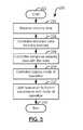
- FIG. 3is a flowchart illustrating operation of a luminaire, according to an embodiment of the present invention.
- FIG. 4is a flowchart illustrating detection of a condition in an environment, according to an embodiment of the present invention.
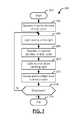
- FIG. 5is a flowchart illustrating an analysis of sensory data and controlling a light source, according to an embodiment of the present invention.
- FIG. 6is a flowchart illustrating an analysis of sensory data from a plurality of sensors and controlling a light source, according to an embodiment of the present invention.
- FIG. 7is a flowchart illustrating an operation of a light source with a duty cycle, according to an embodiment of the present invention.
- FIG. 8is a flowchart illustrating an inclusion of an identifier in a signal, according to an embodiment of the present invention.
- FIG. 9is a diagram illustrating inclusion of a light identifier in a light signal, according to an embodiment of the present invention.
- FIG. 10is a flowchart illustrating emission of signals with identifiers to determine a spatial awareness, according to an embodiment of the present invention.
- FIG. 11is a graph illustrating signals emittable by the luminaire with differing velocities, according to an embodiment of the present invention.
- FIG. 12is a block diagram illustrating signals being received by a luminaire to determine a spatial location, according to an embodiment of the present invention.
- FIG. 13is a block diagram illustrating signals reflected from an environmental object and being received by a luminaire to determine a spatial awareness, according to an embodiment of the present invention.
- FIG. 14is a flowchart illustrating a comparison of signals to determine a spatial awareness, according to an embodiment of the present invention.
- FIG. 15is a schematic diagram illustrating a network of nodes, according to an embodiment of the present invention.
- FIG. 16is a flowchart illustrating an analysis of sensory data sensed by a sensor and a network connected device, according to an embodiment of the present invention.
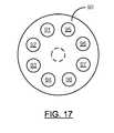
- FIG. 17is a schematic diagram illustrating an interface, according to an embodiment of the present invention.
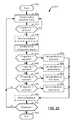
- FIG. 18is a flowchart illustrating use of the interface of FIG. 17 to manipulate rules, according to an embodiment of the present invention.
- FIGS. 19-22are flowcharts illustrating examples of using the interface illustrated in FIG. 17 to manipulate rules, according to an embodiment of the present invention.
- the luminaire 10may also be referred to as a system, device, lighting device, or the invention. Alternate references of the luminaire 10 in this disclosure are not meant to be limiting in any way.
- the luminaire 10may include a controller 20 , an interface 30 with inputs 32 , a light source 40 , and sensors 50 .
- the controller 20may be a microcontroller, gate array, system-on-a-chip, general purpose processing element, or collections of electronic components capable of processing data.
- the controller 20may further include a central processor 22 (CPU), memory 24 , network interface 60 that may be connected to a network 62 , and/or an input/output (I/O) interface 26 .
- CPUcentral processor 22
- memory 24memory 24
- network interface 60may be connected to a network 62
- I/Oinput/output
- the light source 40may include one or more light emitting semiconductor device, such as a light emitting diode (LED).
- LEDlight emitting diode
- the light source 40may be discussed in this disclosure as including light emitting diodes capable of emitting light in a source wavelength range, other light sources 40 may be used.
- light emitting semiconductor devicesmay be used to provide illumination.
- Other embodiments of the present inventionmay include a light source 40 that is generated by a laser device.
- light sources 40that are not semiconductor-based are intended to be included within the scope of the present invention.
- the light from the light source 40could be provided by any number of lighting technologies, each of which are intended to be included within the scope and spirit of the present invention.
- a controller 20may be included in the luminaire 10 .
- the controller 20may include a processor 22 , memory 24 , network interface 60 , and an I/O interface 26 .
- One or more of these components of the controller 20may be located outside of the controller 20 and/or communicatively connected to the controller 20 .
- the processor 22may be configured to receive a data signal from additional components of the luminaire 10 , such as a sensor 50 or the interface 30 .
- the controllermay be carried by a radio logic board, and that the luminaire may include an antenna coupled to the radio logic board.
- the antennamay, for example, be used to transmit a signal that caries data.
- the radio logic boardmay be separated from heat producing elements of the luminaire by a buffer distance.
- the buffer distanceis a distance suitable to facilitation reduction of attenuation of the signal. Additional details and illustrations of the radio logic board, as well as the buffer distance where the radio logic board is positioned, are set forth in U.S. Provisional Patent Application No. 61/486,314 titled WIRELESS LIGHTING DEVICE AND ASSOCIATED METHODS filed on May 15, 2011, the entire contents of which are incorporated herein by reference.
- the processor 22may compute and perform calculations to the data that has been received from the additional components.
- the processor 22may receive sensory data from motion detector 52 , such as an infrared motion detecting sensor.
- the processor 22may then analyze the data to determine whether the characteristics of the data are indicative of motion in the environment, if the processor 22 determines that the sensory data is indicative of motion, the processor 22 may generate a control signal indicating that motion has been detected.
- This control signalmay be used to control a mode of operation for the luminaire 10 , which may include controlling the level of light emitted by the light source 40 , optionally further including controlling the duty cycle of one or more light source 40 .
- the controller 20may also include memory 24 .
- the memory 24may include volatile and/or non-volatile memory modules. Volatile memory modules may include random access memory, which may temporarily store data and code being accessed by the processor 22 .
- the non-volatile memorymay include flash based memory, which may store a computerized program to be operated on the processor 22 .
- the memorymay also store sensory data detected by one or more of the sensors 50 .
- the memory 24may include the computerized code used by the processor 22 to control the operation of the luminaire 10 .
- the memory 24may also store feedback information related to the operation of additional components included in the luminaire 10 .
- the memory 24may include an operating system, which may additionally include applications to be run from within the operating system, as will be appreciated by a person of skill in the art.
- the memory 24may include information to be analyzed by the processor 22 .
- This informationmay include the states of the various inputs 32 , data received from the sensors 50 , modes of operation, and rules to govern the analysis of the aforementioned information.
- the rulesmay be included in memory 24 to define an operation to be performed on the information, a comparison between various pieces of information, or otherwise define the operation of the various embodiments of the present invention. Preexisting rules may be programmed into the memory 24 . Additionally, rules may be defined or modified by a user. The rules may be defined or modified, for example, and without limitation, through an interface 30 .
- the controller 20may also include an I/O interface 26 .
- the I/O interface 26may control the receipt and transmission of data and/or signals between the controller 20 and additional components.
- the I/O interface 26may receive a sensory signal from a sensor, which may be indicative of a condition of the environment. After the processor 22 has analyzed the signal, it may use the I/O interface 26 to transmit a control signal to the light source 40 to affect the light emitted.
- the sensors 50may include any number of sensory devices to detect a condition in the environment.
- the sensors 50may be directly connected to the controller 20 through a wired and/or wireless connection.
- sensors 50may communicate with the controller 20 through a network 62 .
- These network 62 connected sensors 50may be positioned independently of a luminaire 10 , or may alternatively be included and operated in another luminaire 10 within the network 62 .
- examples of motion detection, ambient light detection, and timing sensors 50will be discussed throughout this disclosure. Those of skill in the art will appreciate that these specific example are discussed in the interest of clarity, and are not intended to limit the present invention to those examples.
- a motion detector 52may be defined as an electronic device that detects motion in an environment and generates an electronic signal relative to that motion.
- the motion detector 52may transmit and/or receive one or more signals to detect motion. These signals may include, but should not be limited to, infrared, ultrasonic, microwave, and radio waves.
- the detectionmay passive, such as with an infrared sensor 50 detecting body heat moving within an environment.
- the detectionmay alternatively be active, such as with an ultrasonic emitter emitting a wave and detecting its reflection from an object in the environment.
- the motion detector 52may include a passive infrared (PIR) sensor 50 for the detection of motion.
- the motion detector 52may detect differing levels of motion, from which a signal may be analyzed.
- the sensitivity and operation of the motion detector 52may be adjustable using the interface 30 .
- the motion detector 52may be enabled or disabled using the interface 30 .
- the motion detector 52may additionally be configured to transmit a signal when motion may be absent from the field of view in the environment for a period of time, which may also be adjustable by the user.
- an ambient light detector 54may include one or more photosensors and/or photodetectors to sense a level of ambient light in an environment.
- ambient lightmay be defined as the light existing in an environment that is not being provided by the luminaire 10 .
- Ambient light sensors 50may include one of a plurality of sensors 50 that would be appreciated by those of skill in the art to detect a light level in the environment.
- Example of ambient light detectors 54may include silicon light sensors, active pixel sensors, charge-coupled devices, CMOS sensors, LEDs configured in reverse-bias, optical detectors, photoresistors, photodiodes, photovoltaic cells, a combination of one or more of the aforementioned sensors, or any number of additional sensors that would be apparent to a skilled artisan.
- the operation of the ambient light sensor 50may be synchronized with the operation of the light source 40 . This synchronization may be controlled by the controller 20 .
- the ambient light detector 54may include a silicon light sensor. This non-limiting example of an ambient light detector 54 may estimate the ambient light conditions in the environment in which the luminaire 10 is operating. Differing signals may be transmitted to the controller 20 for analysis depending on the ambient light levels detected in the environment. In one embodiment, the luminosity of ambient light may be classified in as few as two levels, such as day and night. In other embodiments, the luminosity of ambient light may be classified in as many as a virtually limitless number of levels. These levels may be definable using the interface 30 . The interface may be used to add or remove levels, enable or disable the ambient light detector 54 , or otherwise configure the operation of the ambient light detector 54 .
- a timer 56may also be included as a sensor 50 to determine a quantity of time that may have elapsed from a starting point.
- the timer 56may be configured to detect the amount of time that has elapsed since the occurrence of an event, the event being definable by the rules.
- the timer 56may also begin counting down after an event has been detected, the expiration of which being definable to initiate another event.
- An example of an eventmay include a change in the state of the light source 40 , such as to provide additional or decreased illumination. Operation of the timer 56 will be discussed in greater detail below. The operation in the foregoing examples may be defined by the rules.
- the luminaire 10may be operated in a part night operation.
- the luminaire 10may operate normally upon the detection of low luminosity in the environment, such as a dark environment. Normal operation may include illuminating the environment with a medium to high output of light.
- the timer 56may begin counting. Skilled artisans will appreciate that the timer 56 may count increment or decrement, as it may be definable in the rules, as would be consistent with the scope and spirit of the present invention.
- the luminaire 10may further reduce the output of light emitting from the light source 40 . This output reduction may include adjusting at least one light source 40 to emit no light.
- the controller 20 of the luminaire 10may additionally be configured to receive data from the motion detector 52 .
- the output of light provided by the light source 40may be adjusted in further relation to the data received by the controller 20 from the motion detector 52 .
- the timer 56may have expired, resulting in the controller controlling the light source to emit virtually no light.
- An objectmay cause motion in the environment, which may be detected by the motion detector 52 .
- the controller 20 of the luminaire 10may analyze the data relating to detected motion and control the light source 40 to increase its output to approximately full output.
- the luminaire 10may further be defined to reduce the output time after motion is no longer detected.
- the luminaire 10may include a light source 40 .
- the light source 40may include LEDs configured to illuminate an environment in which the luminaire 10 is located.
- a person of skill in the artwill appreciate that, although the light source 40 may be discussed as an LED herein, any device capable of producing light to illuminate an area may be included within the scope of the present invention.
- An LEDmay emit light when an electrical current is passed through the diode, typically in the forward bias.
- the LEDmay be driven by the passing electrical current to provide an electroluminescence, or emission of light.
- the color of the emitted lightmay be determined in part by the materials used in the construction of the light emitting semiconductor.
- the light source 40may emit a light in various spectrums of light.
- the light source 40may emit a light in the visible spectrum. This visible light may illuminate an environment, advantageously deterring the presence of trespassers.
- the light source 40may emit a light in the infrared spectrum. This infrared light may illuminate an environment with a light that is not typically visible to the human eye, but may be visible to another device, such as a camera with a video sensor capable of detecting infrared light.
- the cameramay be communicatively connected to the luminaire 10 , for example through a network 62 , or be provided as a stand-alone device separate from the luminaire 10 .
- the use of infrared lightmay advantageously allow the luminaire 10 to assist another device to monitor and detect motion in an area when light within the visible spectrum is not being emitted.
- a conversion materialmay be applied to the LEDs to create a desired output color.
- the inclusion of a conversion materialmay advantageously allow the luminaire 10 of the present invention to include high efficacy LEDs, increasing the overall efficiency of the luminaire 10 .
- conversion materialsmay be included to convert the light emitted by a light source 40 , such as a conversion phosphor, delay phosphor, or quantum dot, to modify or increase the light outputted by the light source 40 .
- the source wavelength range of the light generated by the light source 40may be emitted in a blue wavelength range.
- LEDs capable of emitting light in any wavelength rangesmay be used in the light source 40 , in accordance with this disclosure of the present invention.
- additional light generating devicesthat may be used in the light source 40 that may be capable of creating an illumination.
- the lighting sourcemay generate a source light with a source wavelength range in the blue spectrum.
- the blue spectrummay include light with a wavelength range between 400 and 500 nanometers.
- a source light in the blue spectrummay be generated by a light emitting semiconductor that is comprised of materials that may emit a light in the blue spectrum. Examples of such light emitting semiconductor materials may include, but are not intended to be limited to, zinc selenide (ZnSe) or indium gallium nitride (InGaN). These semiconductor materials may be grown or formed on substrates, which may be comprised of materials such as sapphire, silicon carbide (SiC), or silicon (Si).
- SiCsilicon carbide
- Sisilicon
- the conversion materialmay include a phosphor substance, which may be applied or located adjacent to the blue LEDs.
- the phosphorous substancemay which may absorb wavelength ranges of emitted by the LEDs and emit light defined in additional wavelength ranges when energized. Energizing of the phosphor may occur upon exposure to light, such as the source light emitted from the light source.
- the wavelength of light emitted by a phosphormay depend on the materials from which the phosphor is comprised.
- the luminaire 10may include a network interface 60 .
- the network interface 60may be included within the controller 20 discussed above. Alternately, a skilled artisan will appreciate that the network interface 60 may be operatively connected to the controller 20 , wherein it may operate as an interface device between the controller 20 and a connected network 62 , such as for example, a home network, corporate network, or the Internet.
- the network interface 60may provide a channel for the electronic communication of data between the luminaire 10 and a connected device connected through the network 62 .
- network connected devicesmay include additional luminaires 10 , personal computers, tablets, smartphones, personal data assistants, a data center, remote, key fob, a light switch, or other electronic devices capable of connecting to a network 62 .
- the network interface 60may connect to a network 62 using a proprietary or standard connection protocol. With respect to embodiments of the present invention that include a proprietary network connection, the network interface 60 may perform handshake operations and exchange data with network 62 connected devices, as may be defined within the proprietary protocol. Alternately, the network interface 60 may connect to a network 62 using a standardized protocol. Examples of standardized protocols, provided without the intent to be limiting, may include 802.3 Ethernet, 802.11 Wi-Fi, 802.15.1 Bluetooth, 802.15.4 low rate personal area network 62 (PAN) environments, packet switching wide area networks (WAN), cellular relay WANs, or additional standardized data transmission protocols.
- PANpersonal area network 62
- WANpacket switching wide area networks
- cellular relay WANsor additional standardized data transmission protocols.
- the datamay be transmitted and received throughout a network 62 by emitting and detecting light.
- the lightmay be modulated such to include transmittable data.
- the datawill be transmitted in the light digitally by modulating between the emission and non-emission of light during a period.
- the datamay be transmittable by modulating the analog frequency or amplitude of the light, or other emitted signal.
- the lightmay be detectable by a sensor, such as, for example, the ambient light sensor, during the periods of the duty cycle in which no light is being emitted. A person of skill in the art will appreciate that these periods may be short enough to be unperceivable by the human eye.
- the network 62may be transmittable using an auxiliary signal, such as an ultrasonic or Wi-Fi signal.
- the luminaire 10may additionally include an interface 30 to control its operation.
- the interface 30may include a plurality of inputs 32 , which may be manipulated by a user to define the operation of the luminaire 10 .
- a person of skill in the artwill appreciate that as few as one input 32 may be included in the interface 30 and be contemplated by the scope of this disclosure. Similarly, a skilled artisan will appreciate that the maximum number of inputs 32 may be virtually limitless.
- a moderate number of inputs 32for example eight inputs 32 , may be included in the interface 30 to advantageously allow a diverse combination of controls to be selectable by the user without rendering the luminaire 10 overly complex.
- an input 32may be defined as an element of the interface 30 through which the operation of the luminaire 10 may be modified.
- the input 32may be provided by any number of means such as, for example, a mechanical toggle, a capacitive sensor, or any other system, device or apparatus suitable to cause the transmission of a signal to the controller 20 .
- the input 32may be a mechanical toggle, which may be physically engaged and mechanically altered to change the state of the toggle.
- the mechanical toggle inputs 32may be a switch that open or dose an electrical circuit upon being manipulated.
- an input 32may be a capacitive sensor.
- the state of a capacitive sensor input 32may be altered upon the detection of an object located in proximity of the capacitive sensor.
- Skilled artisanswill appreciate that a capacitive sensor may detect the proximity of an object using position, displacement, humidity, fluid level, acceleration, or other measurable changes in capacitance. Additional inputs 32 will be appreciated by a person of skill in the art.
- An example of an objectmay include the finger of a user, without limitation.
- the signal resulting from the touchmay be received by the controller 20 , which may be analyzed to determine a state of operation for the luminaire 10 .
- the inputs 32may be located on a surface of the luminaire 10 .
- the inputs 32may be operatively connected to the luminaire 10 , such that the inputs 32 may be in communication with the controller 20 .
- the inputs 32may be remotely connected to the luminaire 10 , which may transmit a signal to be received by a sensor, network interface 60 , or other component.
- Skilled artisanswill appreciate that the aforementioned examples of connective structures are provided in the interest of clarity, and should not limit the present invention to the preceding examples.
- the network 62 connected devicemay be an additional luminaire 10 .
- the controllers 20 of the additional luminaires 10may be controlled the operation of the additional luminaires 10 in response to the electronic signal transmitted over the network 62 .
- additional devicesthat may be connected via the network interface 60 , such as devices with recording capabilities, sirens, indicators, or dialers that may contact police or a security department.
- the luminaire 10may advantageously provide dynamic illumination of an environment with significant customizability in its operation.
- the luminaire 10may detect one or more conditions present in an environment to affect how the environment may be illuminated by the luminaire 10 .
- a series of flowchartswill now be presented, along with accompanying descriptions, to illustrate various embodiments of the present invention. A person of skill in the art will appreciate that the follow flowcharts and descriptions are presented in the interest of clearly disclosing the invention, according to a number of its embodiments. Skilled artisans should not view the present invention to be limited to the embodiments discussed below.
- a sensor 50may sense a condition in the environment (Block 194 ).
- the data generated by the sensor 50 relating to the detected conditionmay be received and analyzed by the controller 20 (Block 196 ).
- the controller 20may then control the light source 40 with respect to the analysis performed on the data (Block 198 ).
- the operationmay then terminate at Block 199 .
- a sensor 50may detect a condition of the environment (Block 204 ).
- the conditionmay include motion, ambient light levels, or additional conditions that would be apparent to a person of skill in the art.
- the sensor 50may then generate sensory data relating to the detected condition (Block 206 ).
- the sensor 50may be an ambient light detector 54 that senses a high level of ambient light in the environment.
- the ambient light detector 54may generate a digital signal, such as a hex value of FE, to convey the condition to controller 20 .
- analog signalsmay also be detectable by the controller 20 , for example by correlating voltage levels with the level in which the condition is detected in the environment.
- the controller 20may then receive the sensory data from the sensor 50 for analysis (Block 208 ).
- the sensory datamay have been made available by the sensor 50 to be received by the controller 20 .
- Skilled artisanswill appreciate the data may be communicated between the sensor 50 and the controller 20 via transmission by the sensor, polling by the controller 20 , or other communications of data that would be readily apparent to after having the benefit of this disclosure.
- the operationmay then terminate at Block 210 .
- the controller 20may receive sensory data from at least one of the sensors 50 (Block 224 ). The controller 20 may then retrieve rules from the memory 24 (Block 226 ). The memory 24 may be included in the controller 20 . Alternatively, the memory 24 including at least some of the rules may be operatively connected to the controller 20 and accessible by the controller 20 .
- the controller 20may then analyze the data, for example, by comparing the sensory data with the rules (Block 228 ). After the data has been analyzed, the controller 20 may adjust the mode of operation of the luminaire 10 (Block 230 ). Various modes, according to an embodiment of the present invention, may include full output, limited output, emission of light that includes data, emission of light that includes an identifier, flashing or blinking light, or other various operational modes that would be apparent to a skilled artisan after having the benefit of this disclosure. The controller 20 may then control the light source 40 to emit light in accordance with the mode of operation, as determined by analyzing the data (Block 232 ). The operation may then terminate at Block 234 .
- the light sourcemay be operated in many different ways. Embodiments of the present invention specifically contemplate operation of the light source by dimming the light source and by moving the light source between an on position and an off position.
- the controller 20may receive sensory data from a plurality of the sensors 50 (Block 244 ).
- the controller 20may then retrieve rules from the memory 24 (Block 246 ).
- the memory 24may be included in the controller 20 .
- the memory 24 including at least some of the rulesmay be operatively connected to the controller 20 and accessible by the controller 20 .
- the controller 20may then analyze the data, for example, by comparing the sensory data with the rules, respective to each of the plurality of sensors 50 from which data has been received (Block 248 A, 248 B, . . . , 248 n ). After the data from the plurality of sensors 50 has been analyzed, the controller 20 may adjust the mode of operation of the luminaire 10 , respective to the analysis performed on the data that may have been received by each of the plurality of sensors (Block 250 A, 250 B, . . . , 250 n ).
- Various modesmay include full output, limited output, emission of light that includes data, emission of light that includes an identifier, flashing or blinking light, or other various operational modes that would be apparent to a skilled artisan after having the benefit of this disclosure.
- the controller 20may then control the light source 40 to emit light in accordance with the mode of operation, as determined by analyzing the data (Block 252 ). The operation may then terminate at Block 254 .
- the controller 20may control the light source 40 to emit light with a duty cycle.
- the duty cyclemay include an active duration and an inactive duration. During the active duration, the light source 40 may emit light. Conversely, during the inactive duration, the light source 40 may not emit light.
- the controller 20may control the light source 40 to emit or to not emit light during the active and inactive durations of the duty cycle, respectively.
- one of the sensors 50may be an ambient light detector 54 (see FIG. 1 ).
- the ambient light detector 54may detect ambient light levels in an inactive portion of the duty cycle. This discussion of an ambient light detector 54 being one of the sensors 50 of the luminaire 20 is provided as an example, and is not intended to limit the present invention in any way.
- the light source 40may be operating in the active duration of the duty cycle (Block 264 ). During the active duration, one or more light sources 40 may emit light (Block 266 ). Skilled artisans will appreciate that beginning this example with the light source 40 operating in the active or inactive duration of the duty cycle was made in the interest of clarity, and without the intent to limit the present invention. Accordingly, the present invention contemplates that this operation may begin with operation the light source in the inactive duration of the duty cycle.
- the luminaire 10may then change to operation in the inactive duration of the duty cycle (Block 268 ).
- one or more light sources 40may stop emitting light (Block 270 ).
- the ambient light detector 54may then detect the ambient light level in the environment (Block 272 ). Since light is not being emitted by the light sources 40 during the inactive duration of the duty cycle, the ambient light sensor 50 may detect ambient light levels in the environment without interference from the light emitted by one or more light source 40 .
- a shutdown commandmay be issued, for example, as a result of a configuration of the rules using the interface 30 . If no shutdown command has been received at Block 274 , the light source may continue to operate at Block 266 , wherein the light source 40 emits light while operating in the active duration of the duty cycle. Conversely, if a shutdown command is received at Block 274 , the operation may terminate at Block 276 . Effectively, the duty cycle may continually loop until a shutdown command is received.
- the controller 20may generate a digital identifier code (Block 304 ).
- the digital identifier codeis also referred to as a digital watermark.
- the controller 20may control the light source 40 to emit the digital identifier code in the light (Block 306 ).
- the identifier light 282may be emitted by alternating the emission 286 and non-emission 288 of light in a pattern to indicate a digital signature, as will be appreciated by skilled artisans.
- a luminaire 10may be encoded with a serial number, which may be transmittable as the identifier in the light 282 .
- the controller 20may include the identifier in the light at an interval, such as every minute, to identify the source of the light.
- the identifiermay be interpreted by another device as “0011 0011 1010 0011 0010.”
- the light source 40may emit light with a standard, or otherwise defined, duty cycle, as illustrated, for example, at Block 308 of FIG. 8 .
- light emitted without inclusion of an identifier light 284may include a duty cycle that alters between the active duration 290 and the inactive duration 292 .
- the controller 20may then determine if it should control the light source 40 to retransmit the light identifier, as illustrated at Block 310 of FIG. 8 . If retransmission of the identifier is desired, the light source 40 may again emit the digital identifier code in the light (Block 306 ).
- the controller 20may determine whether a shutdown command has been received at Block 312 . If no shutdown command has been received at Block 312 , the controller 20 may continue to emit light as normal. If a shutdown command has been received at Block 312 , the operation may terminate at Block 314 .
- the luminaire 10may emit multiple signals that include multiple identifiers.
- the multiple identifiersmay correlate the multiple signals. Additionally, the multiple signals may be transmittable substantially simultaneously, such that analysis on the transmission and or receipt of the signals may be performed by the controller 20 .
- the light and the auxiliary signalallow the luminaire to become spatially aware of an environment in which the luminaire is located. Similarly, the luminaire may use the light and the auxiliary signal to become aware of other objects and devices in the environment. Spatial awareness may include, but should not be limited to, geolocation, positioning, direction finding, and other analytical processes based on the spatial location of the luminaire in an environment.
- the auxiliary signalmay include acoustic energy.
- Acoustic energymay include signals with a frequency that is subsonic, audible, or ultrasonic.
- the auxiliary signalmay be ultrasonic, or a sound with a frequency greater than the upper limits of human hearing.
- the controller 20may designate light with a light identifier (Block 344 ).
- the controller 20may also designate an auxiliary signal with an auxiliary signal identifier (Block 346 ).
- the light identifier and the auxiliary signal identifiermay be correlated with one another.
- the designation of an identifier with light and an auxiliary signalmay happen in any order, or substantially simultaneously.
- the controller 20may control the light source 40 to emit the light and the auxiliary signal emitter to emit auxiliary signal substantially simultaneously (Block 348 ). The operation may then terminate at Block 350 .
- Light, auxiliary signals, and other signals including one or more identifiermay be identifiable by luminaires 10 or other devices. This identification of signals, and an association to its source, may be used to perform analyses on the signals. For example, the detection of identified light by a luminaire 10 that has been emitted by another luminaire 10 in an environment may indicate the presence of a network 62 of luminaires 10 . As another example, receiving a plurality of signals associated with a source luminaire 10 may be used to calculate a distance between the devices. Skilled artisans will appreciate the following examples to be provided for illustrative purposes, and without limitation.
- Graph 360plots the distance traveled by a signal along the y-axis and the time of travel along the x-axis. A desired travel distance has been indicated by the line labeled 367 .
- the velocity at which light 362 and the auxiliary signal 364 travels through the environmentmay differ.
- light 362travels at approximately 3 ⁇ 10 ⁇ 8 meters per second.
- the light 362may reach the desired travel distance 367 at time t 1 .
- the auxiliary signal 364may be a signal of acoustic energy, such as an ultrasonic signal that travels at approximately 340 meters per second.
- the auxiliary signal 364may reach the desired travel distance 367 at time t 2 .
- the difference between t 1 and t 2may be a delay represented by the delta range 368 .
- This delaymay be analyzed to determine the distance of the luminary from another device or object.
- the other devicemay be an additional luminaire 10 .
- multiple luminaires 10may be included as nodes in a network of nodes 70 , each of which being spatially aware with regard to the other nodes in the network of nodes.
- light 362 and an auxiliary signal 364may be emitted from a first luminaire 352 to be received by a second luminaire 10 354 .
- These signals 362 , 364may be emitted substantially simultaneously from the first luminaire 352 .
- the delay between receiving the light 362 and the auxiliary signal 364may be calculated by the second luminaire 354 to determine its distance from the first luminaire 352 .
- the delaymay be calculated by the controller 20 of the luminaire 354 .
- light 362 and an auxiliary signal 364may be emitted from a luminaire 356 into an environment that includes an environmental object 358 .
- the light 362 and the auxiliary signal 364may be reflected by the object and be received by the luminaire 356 .
- the luminaire 356may then calculate the delay between the emission and the detection of the light 362 and the auxiliary signal 364 to determine the distance of the environmental object 358 from the luminaire 356 .
- the luminaire 356may take in account the additional delay caused by the initial transmission and reflective transmission of the signals 362 , 364 to and from the environmental object 358 , respectively.
- a person of skill in the artwill appreciate additional configurations of luminaires 10 , environmental objects 358 , and other devices that would allow the luminaire 10 to be spatially aware after having the benefit of this disclosure.
- the luminaire 10may attempt to sense light (Block 374 ).
- the lightmay be sensed by a sensor 50 communicatively connected the controller 20 .
- the controller 20may then determine whether light is sensed (Block 376 ).
- Embodiments of the present inventioncontemplate use of an algorithm to conduct a delay/distance calculation. If light is sensed at Block 376 , the controller 20 may determine if a light identifier is included in the light (Block 378 ). If no light is sensed at Block 376 , or if light is sensed that does not include a light identifier, the luminaire 10 may continue attempting to sense light (Block 374 ).
- the luminaire 10may attempt to sense an auxiliary signal, such as an ultrasonic signal (Block 380 ).
- the auxiliary signalmay be sensed by a sensor 50 communicatively connected the controller 20 .
- the controller 20may determine whether an auxiliary signal is sensed (Block 382 ). If an auxiliary signal is sensed at Block 382 , the controller 20 may determine if an auxiliary signal identifier is included in the auxiliary signal (Block 384 ). If no auxiliary signal is sensed at Block 382 , or if auxiliary signal is sensed that does not include an auxiliary signal identifier, the luminaire 10 may continue attempting to sense an auxiliary signal (Block 380 ).
- the controller 20may compare the identifiers for the light and the auxiliary signal (Block 386 ). The controller 20 may then determine if the identifiers correlate at Block 388 .
- Embodiments of the present inventioncontemplate synchronization of the signals. This can be accomplished using time stamps, for example, that may be embedded in the signals.
- the controller 20may optionally determine if an unreasonable amount of time has elapsed (Block 390 ).
- An unreasonable amount of timemay be relative to a time period wherein a delay between receiving light with a light indicator and an auxiliary signal with a correlating auxiliary signal indicator would be unreasonable given the space of the environment.
- Unreasonableness of timemay be defined in the rules. Unreasonableness of time may also be defined or configured by a user, for example, using the interface 30 .
- the operationmay again attempt to sense an auxiliary signal at Block 380 . If it is determined that an unreasonable amount of time has elapsed at Block 390 , the operation may again attempt to sense light at Block 374 , essentially restarting. If it is determined at Block 388 that the light identifier and the auxiliary signal identifier correlate, the controller 20 may calculate the delay between receiving the identified signals to determine a distance from the origin of the signals, and thus the spatial location of the luminaire 10 (Block 392 ). The operation may terminate at Block 394 .
- components included in the luminaire 10may be included as a node within a network 62 , such as a network of nodes 70 .
- the luminaire 10may communicate with one or more additional luminaires 10 over the network 62 .
- luminaires 10 and additional devicesmay be connected over the network 62 69 by using a centralized hub or outer.
- each device on the network 62 69may be included in a network of nodes 70 , for example, and without limitation, a neural network 62 .
- a nodemay include a sensor, a controller 20 , and additional components of the luminaire 10 such as a light source 40 and/or an auxiliary signal emitter.
- the components of the nodemay be included in a luminaire 10 .
- Each nodemay operate as a master and a slave. Additionally, each node may act as a repeater to expand the range of the network 62 69 .
- FIG. 15an illustrative embodiment to a network of nodes 70 will now be discussed.
- a plurality of nodesmay be positioned within communication range of additional nodes.
- a person of skill in the artwill appreciate that the configuration of nodes illustrated in FIG. 15 has been chosen in the interest of clarity, as the nodes may be configured in a plethora of additional locations relative to one another.
- each nodemay communicate with its neighboring nodes by sending and receive data directly with one another.
- Node 2 Amay transmit a direct data communication as a master to be received by Node 2 B as a slave. This data communication may not require involving additional nodes 72 .
- additional nodes 72may still receive the data communication, analyze any information included in the data communication, and disregard any message to which the additional node 72 is not an intended recipient.
- a person of skill in the artwill appreciate that communication of a node 72 with a non-neighboring node 72 is also contemplated by the scope of the present invention, and is intended to be included in this disclosure.
- nodes 72may be configured to repeat messages that are addressed to another node 72 in the network of nodes 70 .
- Node 2 Amay intend to transmit a data communication as a master to Node 1 C as a slave.
- Node 2 Amay broadcast the data transmission, even though Node 1 C is out of range to receive the transmission.
- the datamay be received by Node 2 B as a slave, which may be in range of Node 2 A.
- Node 2 Bmay determine that it is an unintended recipient, Node 2 B may then retransmit the data communication as the master, which may now be received by Node 1 C as the slave, since Node 1 C may now be in range of the transmitting master node.
- the controller 20 at each nodemay include memory 24 .
- the memory 24 of the nodemay maintain an at least partial log of data communication 80 that have been transmitted, received, and or rebroadcast by the node 72 .
- the network of nodes 70is a neural network
- the controller 20 of a node 72may then access the memory 24 to compare the data included in the memory of that node 72 with the received data.
- the controller 20 of the node 72may then make a logic based decision as a result of the analysis.
- An example of such a logic based decisionmay include declining to rebroadcast a data communication that has already been rebroadcast by the node 72 .
- An additional example of a logic based decisionmay include broadcasting a confirmation signal to a transmitting master node, such as node 3 B, indicating that the data transmission has been received from Node 3 C.
- the Node 3 C transmitting the data communication as a master nodemay receive the confirmation signal from Node 3 B as a slave node.
- Node 3 Cmay then analyze the confirmation signal to make a logic based decision to terminate further transmission of the original data communication.
- each node 70may receive and transmit multiple signal and data transmissions among each other. These signals may include, for example, the light and auxiliary signal transmissions usable to determine the spatial awareness between the nodes within the network of nodes 70 . As the nodes 72 become aware of one another, and as data is shared between the nodes 72 , advanced analysis of the data detected by the sensors 50 of each node 72 may be performed. Examples of such advanced analysis may include concatenation of the sensed environmental conditions with respect to the spatial location of each node 72 . This concatenation may create a map of conditions sensed throughout the environment, for example.
- the sharing of data between nodes 72 within the network of nodes 70may additionally allow a controller 20 of one node 72 analyze a condition sensed by another node 72 .
- An example of this distributed sensing, using both sensors 50 locally included within a node and distributed through a network of nodes 70will now be discussed with reference to flowchart 400 of FIG. 16 . Skilled artisans will appreciate that the following example is but one embodiment of the present invention, and thus should not be viewed as limiting.
- the controller 20may analyze sensory data from a local sensor, or a sensor 50 directly connected to the controller 20 (Block 404 ). The controller 20 may then determine if a condition was detected by the local sensor (Block 406 ). If a condition was detected, the operation may advance to Block 412 , wherein the controller 20 may control the light source 40 respective to the sensed conditions, as may be defined by the rules.
- the controller 20may determine whether a communication signal is detected (Block 408 ).
- a communication signalmay be any signal that carries a communication from another device, such as an additional luminaire 10 that may be a node 72 in the network of nodes 70 . If no communication signal is detected at Block 408 , the operation may return to Block 404 , wherein the controller 20 may analyze sensed data from a local sensor. If a communication signal is detected at Block 408 , the controller 20 may determine whether the communication signal is indicative of a condition detected by a sensor 50 of a network 62 connected device (Block 410 ). The network 62 connected device may be another luminaire 10 within the network 62 .
- the operationmay return to Block 404 , wherein the controller 20 may analyze sensed data from a local sensor. If the signal is determined to be indicative of a condition detected by a sensor 50 of a network 62 connected device at Block 410 , the operation may advance to Block 412 , wherein the controller 20 may control the light source 40 with respect to the sensed conditions, as may be defined by the rules. The operation may then terminate at Block 414 .
- the luminaire 10may include a network interface 60 .
- the luminaire 10may communicate with network connected over a network 62 devices using the network interface 60 .
- Such communicationsmay include receiving control instructions, firmware updates, or other data instructions that may affect the operation of the luminaire 10 of the present invention.
- the network interface 60may also allow the luminaire 10 to transmit a data signal to a connected network device.
- data signalsmay include feedback information, status updates, identity, and other information detected by the luminaire 10 .
- An embodiment of a network 62 connected devicemay include a computerized device capable of running computer programs. More specifically, the computerized network connected device may be connected to the network 62 to perform one or more analyses, which may result in the determination of operational statistics based at least partially upon feedback by the luminaire 10 .
- the network connected devicemay include, but should not be limited to, a server, a computer (i.e., desktop computer, laptop computer, netbook computer, or any machine having a processor), a dumb terminal that provides an visual interface with a computer or server, a personal digital assistant, mobile communications device such as a cellular phone, smart phone (such as an Google Android based phone), or other similar device that provides computer or quasi-computer functionality.
- the network 62 communicationmay occur through an internal network 62 , an intranet, LAN, WAN, or global communications network 62 (such as the Internet). It should be noted that the method aspects of the present invention are preferably computer-implemented methods and, more particularly, at least one step is preferably carried out using a computerized device.
- the analyses by the controller 20may be performed as defined by the rules, which are storable in the memory 24 .
- the rulesmay be compared to data or other information to determine the operation of the luminaire 10 .
- the rulesmay also define the modes in which the luminaire 10 operates, sensitivity of the sensors, which of the modes should affect operation of the luminaire 10 , and other operation parameters that may relate to the operation of the luminaire 10 .
- the controller 20 of the luminaire 10according to an embodiment of the invention is capable of several other functions, and that the above described functions are exemplary in nature and not intended to be limiting in any way.
- the rulesmay be definable by a user.
- the rulesmay be definable using an interface 30 .
- the structure of an illustrative interface 30has been discussed above. The interaction with the interface 30 to define and manipulate the rules will now be discussed in the following examples, presented without the intent to limit the present invention in any way.
- the interface 30may include a number of inputs 32 manipulable by a user.
- an illustrative interface 90 including eight inputs 91 - 98will be discussed. Skilled artisans will appreciate that more or less inputs may be included and remain within the scope and spirit of the present invention.
- a threshold duration valuewill be discussed. This threshold duration value is simply a variable quantity of time that may be predetermined or otherwise determined by a user. Additional embodiments will be apparent to a person of skill in the art after having the benefit of this disclosure.
- some of the following examplesmay include one or more steps wherein the luminaire 10 will provide feedback. These steps are optional. Feedback may be provided by emitting light from a light source 40 , emitting a sound, or otherwise providing an indication that an input has been received. Furthermore, the following examples include configurations wherein two inputs 32 are manipulated to interact with the interface 30 . A person of skill in the art appreciate that as few as one input 32 and as many as a virtually limitless number of inputs 32 may be manipulated within the scope of the present invention.
- the controller 20may monitor an initial input (Block 424 ).
- the initial inputsare illustrated as inputs 91 - 94 on the illustrative interface 90 of FIG. 17 .
- the controller 20may then determine if the initial input has been engaged at Block 426 .
- the controller 20may determine whether the initial input was engaged for a threshold duration (Block 428 ). If the initial input has not been engaged, or has been engaged for a duration less than the threshold duration, the operation may return to Block 424 wherein the controller 20 will continue to monitor the initial input. If it is determined at Block 428 that the initial input has been engaged for the threshold duration, the luminaire 10 may optionally provide feedback that the initial input has been properly engaged (Block 430 ). Those skilled in the art will appreciate that making the determination of whether or not the input has been engaged for the threshold duration advantageously prevents the inadvertent transmission of a signal upon an accidental engagement of one of the inputs.
- the present inventioncontemplates transmitting a signal upon any engagement of the inputs and that the threshold duration may advantageously be manipulable for any desired duration, i.e., a minimal or no duration, to any desired length of duration.
- the controller 20may determine whether the period in which the subsequent input should be monitored has expired (Block 432 ).
- the subsequent inputsare illustrated as inputs 96 - 98 on the illustrative interface 90 of FIG. 17 . The first time the operation makes this determination, the period will likely not have expired. If the period in which the subsequent input should be monitored has expired, the operation may return to Block 424 , wherein the initial input will again be monitored. If the period in which the subsequent input should be monitored has not expired at Block 432 , the controller 20 may then monitor a subsequent input (Block 434 ).
- the determinationmay then be made whether the initial input has been engaged at Block 436 . If the subsequent input has been engaged, the determination may be made whether the subsequent input has been engaged for a threshold duration (Block 438 ). If the subsequent input has not been engaged, or has been engaged for a duration less than the threshold duration, the operation may return to Block 432 wherein a determination may again be made whether the period in which the subsequent input should be monitored has expired. Similar to the description of engaging the input above, embodiments of the present invention contemplates engaging the subsequent input for any duration, and that monitoring the duration may be optional, i.e., embodiments of the present invention contemplates that the signal may be transmitted upon immediate engagement of the input or upon engagement of the input for a duration.
- the operationmay update the rule accordingly (Block 440 ).
- the luminaire 10may optionally provide feedback that the rule has been successfully updated (Block 442 ).
- the feedbackmay be in any form, i.e., and audible feedback or a visual feedback.
- the feedbackmay be provided by sending a signal through the network that may result in delivery of a message indicating that the rule has been successfully updated.
- the feedbackmay result in delivery of an email, a text message, an instant message, or any other readily transmittable message that indicates that the rule has been successfully updated.
- the controller 20may then determine if a shutdown command has been received at Block 444 . If no shutdown command has been received, the operation may return to Block 424 , wherein the initial input will again be monitored. If a shutdown command has been received at Block 444 , the operation may terminate at Block 446 . A person of skill in the art will appreciate that this operation may be repeated for additional subsequent inputs.
- the controller 20may monitor a delay input (Block 454 ). The controller 20 may then determine if the delay input has been engaged for a threshold duration, such as three seconds (Block 456 ). If the delay input has not been engaged for the threshold duration, the operation may return to Block 454 wherein the controller 20 will continue to monitor the delay input. If it is determined at Block 456 that the delay input has been engaged for the threshold duration, the luminaire 10 may optionally provide feedback that the delay input has been properly engaged (Block 458 ).
- a threshold durationsuch as three seconds
- the controller 20may monitor a set of configuration inputs (Block 460 ).
- the set of configuration inputsmay include one or more inputs that may be engaged by a user to manipulate the rules. Although the following example discusses four configuration inputs, a person of skill in the art will appreciate that any number of configuration inputs may be included in the set of configuration inputs, without limitation.
- the controller 20may determine if a first input has been engaged for a threshold duration (Block 462 ). If it is determined at Block 462 that the first input has been engaged for the threshold duration, the rule relating to the delay may be defined to operate in test mode (Block 464 ). During test mode, the luminaire 10 may operate such that no delay is required and the luminaire 10 will react immediately to illuminate an environment with and without and motion in the field of view.
- the operationmay proceed to Block 466 wherein the controller 20 may determine whether a second input has been engaged for a threshold duration. If it is determined at Block 466 that the second input has been engaged for the threshold duration, the rule relating to the delay may be defined to operate with a delay between detecting motion and emitting light being defined as thirty seconds (Block 468 ). With the delay being defined as thirty seconds, the luminaire 10 may operate such to illuminate an environment in which motion is detected in the field of view for thirty seconds.
- Block 470the operation may proceed to Block 470 wherein the controller 20 may determine whether a third input has been engaged for a threshold duration. If it is determined at Block 470 that the third input has been engaged for the threshold duration, the rule relating to the delay may be defined to operate with a delay between detecting motion and emitting light being defined as two minutes (Block 472 ). With the delay being defined as two minutes, the luminaire 10 may operate such to illuminate an environment in which motion is detected in the field of view for two minutes.
- the operationmay proceed to Block 474 wherein the controller 20 may determine whether a fourth input has been engaged for a threshold duration. If it is determined at Block 474 that the fourth input has been engaged for the threshold duration, the rule relating to the delay may be defined to operate with a delay between detecting motion and emitting light being defined as ten minutes (Block 476 ). With the delay being defined as ten minutes, the luminaire 10 may operate such to illuminate an environment in which motion is detected in the field of view for ten minutes.
- the operationmay proceed to Block 454 , wherein the controller 20 may again monitor whether the delay input has been engaged.
- the luminaire 10may optionally provide feedback that the rule has been successfully changed (Block 480 ).
- the controller 20may then determine if a shutdown command has been received at Block 482 . If a shutdown command has not been received at Block 482 , the operation may proceed to Block 454 , wherein the controller 20 may again monitor whether the delay input has been engaged. If a shutdown command has been received at Block 482 , the operation may terminate at Block 484 .
- the controller 20may monitor an ambient light detector input (Block 494 ). The controller 20 may then determine if the ambient light detector input has been engaged for a threshold duration, such as three seconds (Block 496 ). Again, a threshold duration of three seconds (as illustrated in the flowchart 490 ) is exemplary in nature and not meant to be limiting in any way. The threshold duration can be any duration, and a reading that the threshold duration is limited to three seconds is inappropriate and not intended in any way.
- the operationmay return to Block 494 wherein the controller 20 will continue to monitor the ambient light detector input. If it is determined at Block 496 that the ambient light detector 54 input has been engaged for the threshold duration, the luminaire 10 may optionally provide feedback that the ambient light detector input has been properly engaged (Block 498 ).
- the controller 20may monitor a set of configuration inputs (Block 500 ).
- the set of configuration inputsmay include one or more inputs that may be engaged by a user to manipulate the rules.
- the following examplediscusses four configuration inputs, a person of skill in the art will appreciate that any number of configuration inputs may be included in the set of configuration inputs, without limitation.
- the controller 20may determine if a first input has been engaged for a threshold duration (Block 502 ). If it is determined at Block 502 that the first input has been engaged for the threshold duration, the rule may be defined to disable the ambient light detector 54 (Block 504 ). With the ambient light detector 54 disabled, the luminaire 10 may operate such to illuminate an environment with motion detected in the field of view, regardless of ambient light levels. This may provide for operation during daylight.
- the operationmay proceed to Block 506 wherein the controller 20 may determine whether a second input has been engaged for a threshold duration. If it is determined at Block 506 that the second input has been engaged for the threshold duration, the rule relating to the ambient light detector 54 may be defined to operate during the first three hours that ambient light detector 54 detects low ambient light levels (Block 508 ). In this operation, the luminaire 10 may illuminate an area with a dimmed brightness during the first three hours of low ambient light levels that no motion is detected. Again, the use of three hours as the time within which the luminaire may illuminate the area with a dimmed brightness is exemplary in nature and should not be read to limit any embodiment of the claimed invention in any way.
- the luminairemay illuminate the area with a dimmed brightness for any amount of time. After the first three hours have expired, the luminaire 10 may emit no light in the subsequent hours and wherein no motion is detected. The luminaire 10 may emit light at full brightness upon the detection of motion.
- the operationmay proceed to Block 510 wherein the controller 20 may determine whether a third input has been engaged for a threshold duration. If it is determined at Block 510 that the third input has been engaged for the threshold duration, the rule relating to the ambient light detector 54 may be defined to operate during the first six hours that ambient light detector 54 detects low ambient light levels (Block 512 ). In this operation, the luminaire 10 may illuminate an area with a first brightness during the first six hours of low ambient light levels that no motion is detected. After the first six hours have expired, the luminaire 10 may emit no light in the subsequent hours and wherein no motion is detected. The luminaire 10 may emit light at full brightness upon the detection of motion.
- the operationmay proceed to Block 514 wherein the controller 20 may determine whether a fourth input has been engaged for a threshold duration. If it is determined at Block 514 that the fourth input has been engaged for the threshold duration, the rule relating to the ambient light detector 54 may be defined to operate during the all hours that ambient light detector 54 detects low ambient light levels (Block 516 ). In this operation, the luminaire 10 may illuminate an area with a dimmed brightness during all hours of low ambient light levels and wherein no motion detected. The luminaire 10 may emit light at full brightness upon the detection of motion.
- the operationmay proceed to Block 494 , wherein the controller 20 may again monitor whether the ambient light detector input has been engaged.
- the luminaire 10may optionally provide feedback that the rule has been successfully changed (Block 520 ).
- the controller 20may then determine if a shutdown command has been received at Block 522 . If a shutdown command has not been received at Block 522 , the operation may proceed to Block 494 , wherein the controller 20 may again monitor whether the ambient light detector input has been engaged. If a shutdown command has been received at Block 522 , the operation may terminate at Block 524 .
- the dim levelmay affect the brightness of light emitted by a light source 40 when a low ambient light level is detected without motion being detected in the environment.
- Skilled artisanswill appreciate that the rules manipulable in association with the dim level may be applied in conjunction with other rules, such as the rules relating to ambient light or motion detection.
- the controller 20may monitor a dim input (Block 534 ). The controller 20 may then determine if the dim input has been engaged for a threshold duration, such as three seconds (Block 536 ). If the dim input has not been engaged for the threshold duration, the operation may return to Block 534 wherein the controller 20 will continue to monitor the dim input. If it is determined at Block 536 that the dim input has been engaged for the threshold duration, the luminaire 10 may optionally provide feedback that the dim input has been properly engaged (Block 538 ).
- a threshold durationsuch as three seconds
- the controller 20may monitor a set of configuration inputs (Block 540 ).
- the set of configuration inputsmay include one or more inputs that may be engaged by a user to manipulate the rules. Although the following example discusses four configuration inputs, a person of skill in the art will appreciate that any number of configuration inputs may be included in the set of configuration inputs, without limitation.
- the controller 20may determine if a first input has been engaged for a threshold duration (Block 542 ). If it is determined at Block 542 that the first input has been engaged for the threshold duration, the rule relating to the dim level may be disabled (Block 544 ). With the dim level disabled, the luminaire 10 may operate such that no light is emitted when motion is not sensed in the field of view, regardless of the ambient light levels sensed by an ambient light detector 54 .
- the operationmay proceed to Block 546 wherein the controller 20 may determine whether a second input has been engaged for a threshold duration. If it is determined at Block 546 that the second input has been engaged for the threshold duration, the rule relating to the dim level may be defined to operate at, for example, twenty-five percent brightness (Block 548 ). Similar to the time durations mentioned above, the percentage of brightness described with reference to Block 544 , 548 , 552 , and 556 are merely exemplary and those skilled in the art will appreciate that any brightness level is readily contemplated by the embodiments of the present invention. With the dim level being defined as twenty-five percent, the luminaire 10 may operate one or more light source 40 to illuminate an environment with approximately twenty-five percent brightness when no motion is detected in the environment.
- the operationmay proceed to Block 550 wherein the controller 20 may determine whether a third input has been engaged for a threshold duration. If it is determined at Block 550 that the third input has been engaged for the threshold duration, the rule relating to the dim level may be defined to operate at fifty percent brightness (Block 552 ). With the dim level being defined as fifty percent, the luminaire 10 may operate one or more light source 40 to illuminate an environment with approximately fifty percent brightness when no motion is detected in the environment.
- Block 554the operation may proceed to Block 554 wherein the controller 20 may determine whether a fourth input has been engaged for a threshold duration. If it is determined at Block 554 that the fourth input has been engaged for the threshold duration, the rule relating to the dim level may be defined to disable dimming (Block 556 ). With the dimming being disabled, the luminaire 10 may operate such that it will not respond to motion detected in the field of view. However, in an embodiment, the sensors 50 may continue to detect ambient light levels, which may continue to affect operation of the luminaire 10 .
- the operationmay proceed to Block 534 , wherein the controller 20 may again monitor whether the dim input has been engaged.
- the luminaire 10may optionally provide feedback that the rule has been successfully changed (Block 560 ).
- the controller 20may then determine if a shutdown command has been received at Block 562 . If a shutdown command has not been received at Block 562 , the operation may proceed to Block 534 , wherein the controller 20 may again monitor whether the dim input has been engaged. If a shutdown command has been received at Block 562 , the operation may terminate at Block 564 .
- the sensitivity of motion detection definable in the rulesmay operate in conjunction with other rules, such as the rules relating to the delay or ambient light levels detected. Additionally, in the present example, levels of sensitivity are discussed between a first level and a fourth level, with each level offering increased sensitivity in motion detection. Increased sensitivity may be provided, for example, by increasing the distance in which motion is detectable. A person of skill in the art should appreciate that the present invention should not be limited to four levels of motion detecting sensitivity, and that any number of levels may be added or removed as the desired for the operation of the luminaire 10 .
- the controller 20may monitor a motion sensitivity input (Block 574 ). The controller 20 may then determine if the motion sensitivity input has been engaged for a threshold duration, such as three seconds (Block 576 ). If the motion sensitivity input has not been engaged for the threshold duration, the operation may return to Block 574 wherein the controller 20 will continue to monitor the motion sensitivity input. If it is determined at Block 576 that the motion sensitivity input has been engaged for the threshold duration, the luminaire 10 may optionally provide feedback that the motion sensitivity input has been properly engaged (Block 578 ).
- a threshold durationsuch as three seconds
- the controller 20may monitor a set of configuration inputs (Block 580 ).
- the set of configuration inputsmay include one or more inputs that may be engaged by a user to manipulate the rules. Although the following example discusses four configuration inputs, a person of skill in the art will appreciate that any number of configuration inputs may be included in the set of configuration inputs, without limitation.
- the controller 20may determine if a first input has been engaged for a threshold duration (Block 582 ). If it is determined at Block 582 that the first input has been engaged for the threshold duration, the rule relating to the sensitivity of motion detection may be defined to operate at a first level (Block 584 ). With sensitivity being defined in the rules at the first level, the luminaire 10 may operate to detect motion in an environment with a small the field of view.
- the operationmay proceed to Block 586 wherein the controller 20 may determine whether a second input has been engaged for a threshold duration. If it is determined at Block 586 that the second input has been engaged for the threshold duration, the rule relating to the sensitivity of motion detection may be defined to operate at a second level (Block 588 ). With sensitivity being defined in the rules at the second level, the luminaire 10 may operate to detect motion in an environment with a field of view larger than the first level of sensitivity.
- the operationmay proceed to Block 590 wherein the controller 20 may determine whether a third input has been engaged for a threshold duration. If it is determined at Block 590 that the third input has been engaged for the threshold duration, the rule relating to the sensitivity of motion detection may be defined to operate at a third level (Block 592 ). With sensitivity being defined in the rules at the third level, the luminaire 10 may operate to detect motion in an environment with a field of view larger than the second level of sensitivity.
- the operationmay proceed to Block 594 wherein the controller 20 may determine whether a fourth input has been engaged for a threshold duration. If it is determined at Block 594 that the fourth input has been engaged for the threshold duration, the rule relating to the sensitivity of motion detection may be defined to operate at a fourth level (Block 596 ). With sensitivity being defined in the rules at the fourth level, the luminaire 10 may operate to detect motion in an environment with a field of view larger than the third level of sensitivity.
- the operationmay proceed to Block 574 , wherein the controller 20 may again monitor whether the motion sensitivity input has been engaged.
- the luminaire 10may optionally provide feedback that the rule has been successfully changed (Block 600 ).
- the controller 20may then determine if a shutdown command has been received at Block 602 . If a shutdown command has not been received at Block 602 , the operation may proceed to Block 574 , wherein the controller 20 may again monitor whether the motion sensitivity input has been engaged. If a shutdown command has been received at Block 602 , the operation may terminate at Block 604 .
- the interface 30may include additional inputs, which may be used to define the rules relating to various sensors 50 .
- additional sensorsmay detect temperature, humidity, barometric pressure, altitude, levels of certain gases, presence of vermin or other animals, seismic activity, electromagnetic radioactivity, or intensity of ultraviolet light.
- an alertmay be provided upon detecting a condition of the environment, for example, using one of the sensors listed above. Alerts may include illumination, bunking, flashing, sound, transmitting a data signal, or other providing another form of indication that an condition has been detected or an event has occurred.
- additional inputsmay be provided to allow customization to the rules relating to the additional sensors.
- the inputs 32may be configured to manipulate the rules with different combinations of engagement. The rules relating to the operation of the inputs 32 may even be defined through engagement of the inputs. As such, skilled artisans should not view the present invention as limited to the examples discussed above.
Landscapes
- Engineering & Computer Science (AREA)
- Computer Networks & Wireless Communication (AREA)
- Circuit Arrangement For Electric Light Sources In General (AREA)
Abstract
Description
Claims (84)
Priority Applications (6)
| Application Number | Priority Date | Filing Date | Title |
|---|---|---|---|
| US13/403,531US8674608B2 (en) | 2011-05-15 | 2012-02-23 | Configurable environmental condition sensing luminaire, system and associated methods |
| US13/751,180US8729832B2 (en) | 2011-05-15 | 2013-01-28 | Programmable luminaire system |
| DK13722608.0TDK2818029T3 (en) | 2012-02-23 | 2013-02-22 | Configurable lighting fixture that detects environmental conditions, system and associated practices |
| EP13722608.0AEP2818029B1 (en) | 2012-02-23 | 2013-02-22 | Configurable environmental condition sensing luminaire, system and associated methods |
| PCT/US2013/027226WO2013126633A1 (en) | 2012-02-23 | 2013-02-22 | Configurable environmental condition sensing luminaire, system and associated methods |
| US14/246,917US8933638B2 (en) | 2011-05-15 | 2014-04-07 | Programmable luminaire and programmable luminaire system |
Applications Claiming Priority (4)
| Application Number | Priority Date | Filing Date | Title |
|---|---|---|---|
| US201161486314P | 2011-05-15 | 2011-05-15 | |
| US201161486316P | 2011-05-15 | 2011-05-15 | |
| US201161486322P | 2011-05-15 | 2011-05-15 | |
| US13/403,531US8674608B2 (en) | 2011-05-15 | 2012-02-23 | Configurable environmental condition sensing luminaire, system and associated methods |
Related Child Applications (1)
| Application Number | Title | Priority Date | Filing Date |
|---|---|---|---|
| US13/107,928Continuation-In-PartUS8547391B2 (en) | 2010-07-23 | 2011-05-15 | High efficacy lighting signal converter and associated methods |
Publications (2)
| Publication Number | Publication Date |
|---|---|
| US20120286673A1 US20120286673A1 (en) | 2012-11-15 |
| US8674608B2true US8674608B2 (en) | 2014-03-18 |
Family
ID=48430914
Family Applications (1)
| Application Number | Title | Priority Date | Filing Date |
|---|---|---|---|
| US13/403,531Active - Reinstated2032-04-23US8674608B2 (en) | 2011-05-15 | 2012-02-23 | Configurable environmental condition sensing luminaire, system and associated methods |
Country Status (4)
| Country | Link |
|---|---|
| US (1) | US8674608B2 (en) |
| EP (1) | EP2818029B1 (en) |
| DK (1) | DK2818029T3 (en) |
| WO (1) | WO2013126633A1 (en) |
Cited By (30)
| Publication number | Priority date | Publication date | Assignee | Title |
|---|---|---|---|---|
| US20110210673A1 (en)* | 2008-10-29 | 2011-09-01 | Axel Pilz | Sensor Element Having a Light Sensor, Communication Transmitter Having a Sensor Element, and Lighting System Having a Sensor Element |
| US20130187552A1 (en)* | 2011-05-12 | 2013-07-25 | LSI Saco Technologies, Inc. | Light Harvesting |
| US8933638B2 (en) | 2011-05-15 | 2015-01-13 | Lighting Science Group Corporation | Programmable luminaire and programmable luminaire system |
| US20160037605A1 (en)* | 2012-07-25 | 2016-02-04 | Express Imaging Systems, Llc | Apparatus and method of operating a luminaire |
| US9303825B2 (en) | 2013-03-05 | 2016-04-05 | Lighting Science Group, Corporation | High bay luminaire |
| WO2016064542A1 (en)* | 2014-10-24 | 2016-04-28 | Express Imaging Systems, Llc | Detection and correction of faulty photo controls in outdoor luminaires |
| US9412253B2 (en) | 2014-02-06 | 2016-08-09 | Biological Illumination, Llc | System for detecting and analyzing motion for pattern prediction and associated methods |
| US9433062B2 (en) | 2012-11-19 | 2016-08-30 | Express Imaging Systems, Llc | Luminaire with ambient sensing and autonomous control capabilities |
| US9572230B2 (en) | 2014-09-30 | 2017-02-14 | Express Imaging Systems, Llc | Centralized control of area lighting hours of illumination |
| US9648284B2 (en) | 2011-05-15 | 2017-05-09 | Lighting Science Group Corporation | Occupancy sensor and associated methods |
| US9681108B2 (en) | 2011-05-15 | 2017-06-13 | Lighting Science Group Corporation | Occupancy sensor and associated methods |
| US9693433B2 (en) | 2012-09-05 | 2017-06-27 | Express Imaging Systems, Llc | Apparatus and method for schedule based operation of a luminaire |
| US9713228B2 (en) | 2011-04-12 | 2017-07-18 | Express Imaging Systems, Llc | Apparatus and method of energy efficient illumination using received signals |
| US10098212B2 (en) | 2017-02-14 | 2018-10-09 | Express Imaging Systems, Llc | Systems and methods for controlling outdoor luminaire wireless network using smart appliance |
| US10164374B1 (en) | 2017-10-31 | 2018-12-25 | Express Imaging Systems, Llc | Receptacle sockets for twist-lock connectors |
| US10219360B2 (en) | 2017-04-03 | 2019-02-26 | Express Imaging Systems, Llc | Systems and methods for outdoor luminaire wireless control |
| US20190178711A1 (en)* | 2016-07-28 | 2019-06-13 | Philips Lighting Holding B.V. | Methods and systems for camera-based ambient light estimation |
| US10568191B2 (en) | 2017-04-03 | 2020-02-18 | Express Imaging Systems, Llc | Systems and methods for outdoor luminaire wireless control |
| US10904992B2 (en) | 2017-04-03 | 2021-01-26 | Express Imaging Systems, Llc | Systems and methods for outdoor luminaire wireless control |
| US11212887B2 (en) | 2019-11-04 | 2021-12-28 | Express Imaging Systems, Llc | Light having selectively adjustable sets of solid state light sources, circuit and method of operation thereof, to provide variable output characteristics |
| US11234304B2 (en) | 2019-05-24 | 2022-01-25 | Express Imaging Systems, Llc | Photocontroller to control operation of a luminaire having a dimming line |
| US11317497B2 (en) | 2019-06-20 | 2022-04-26 | Express Imaging Systems, Llc | Photocontroller and/or lamp with photocontrols to control operation of lamp |
| US11375599B2 (en) | 2017-04-03 | 2022-06-28 | Express Imaging Systems, Llc | Systems and methods for outdoor luminaire wireless control |
| US11587673B2 (en) | 2012-08-28 | 2023-02-21 | Delos Living Llc | Systems, methods and articles for enhancing wellness associated with habitable environments |
| US11649977B2 (en) | 2018-09-14 | 2023-05-16 | Delos Living Llc | Systems and methods for air remediation |
| US11668481B2 (en) | 2017-08-30 | 2023-06-06 | Delos Living Llc | Systems, methods and articles for assessing and/or improving health and well-being |
| US11763401B2 (en) | 2014-02-28 | 2023-09-19 | Delos Living Llc | Systems, methods and articles for enhancing wellness associated with habitable environments |
| US11844163B2 (en) | 2019-02-26 | 2023-12-12 | Delos Living Llc | Method and apparatus for lighting in an office environment |
| US11898898B2 (en) | 2019-03-25 | 2024-02-13 | Delos Living Llc | Systems and methods for acoustic monitoring |
| US12439488B2 (en) | 2022-12-09 | 2025-10-07 | Express Imaging Systems, Llc | Field adjustable output for dimmable luminaires |
Families Citing this family (32)
| Publication number | Priority date | Publication date | Assignee | Title |
|---|---|---|---|---|
| US20120235579A1 (en) | 2008-04-14 | 2012-09-20 | Digital Lumens, Incorporated | Methods, apparatus and systems for providing occupancy-based variable lighting |
| US10539311B2 (en) | 2008-04-14 | 2020-01-21 | Digital Lumens Incorporated | Sensor-based lighting methods, apparatus, and systems |
| EP3517839B1 (en) | 2010-11-04 | 2021-09-22 | Digital Lumens Incorporated | Method, apparatus, and system for occupancy sensing |
| CN103843287B (en)* | 2011-10-06 | 2017-10-03 | 飞利浦灯具控股公司 | The network switch and equipment and its operating method include the network of the equipment |
| CA2854784C (en) | 2011-11-03 | 2021-07-20 | Digital Lumens Incorporated | Methods, systems, and apparatus for intelligent lighting |
| EP2829160B1 (en) | 2012-03-19 | 2021-04-21 | Digital Lumens Incorporated | Methods, systems, and apparatus for providing variable illumination |
| US9402294B2 (en) | 2012-05-08 | 2016-07-26 | Lighting Science Group Corporation | Self-calibrating multi-directional security luminaire and associated methods |
| US9174067B2 (en) | 2012-10-15 | 2015-11-03 | Biological Illumination, Llc | System for treating light treatable conditions and associated methods |
| US9345091B2 (en)* | 2013-02-08 | 2016-05-17 | Cree, Inc. | Light emitting device (LED) light fixture control systems and related methods |
| US9271375B2 (en) | 2013-02-25 | 2016-02-23 | Leviton Manufacturing Company, Inc. | System and method for occupancy sensing with enhanced functionality |
| ITMI20130549A1 (en)* | 2013-04-09 | 2014-10-10 | Classic Light S R L | AUTOMATIC ARTIFICIAL LIGHTING DEVICE |
| EP2992395B1 (en) | 2013-04-30 | 2018-03-07 | Digital Lumens Incorporated | Operating light emitting diodes at low temperature |
| US9300484B1 (en) | 2013-07-12 | 2016-03-29 | Smartlabs, Inc. | Acknowledgement as a propagation of messages in a simulcast mesh network |
| US9655207B2 (en) | 2013-08-27 | 2017-05-16 | Philips Lighting Holding B.V. | Sensor network with adaptive detection settings based on the status information from neighboring luminaires and/or connected devices |
| ITPD20130263A1 (en)* | 2013-09-26 | 2015-03-27 | Inwenta Di Tallon Riccardo | APPARATUS AND METHOD FOR THE CONTROL OF A LIGHTING SYSTEM |
| AU2014331746A1 (en) | 2013-10-10 | 2016-05-05 | Digital Lumens Incorporated | Methods, systems, and apparatus for intelligent lighting |
| US9622323B2 (en) | 2013-11-21 | 2017-04-11 | General Electric Company | Luminaire associate |
| US9621265B2 (en) | 2013-11-21 | 2017-04-11 | General Electric Company | Street lighting control, monitoring, and data transportation system and method |
| US9646495B2 (en) | 2013-11-21 | 2017-05-09 | General Electric Company | Method and system for traffic flow reporting, forecasting, and planning |
| US9420674B2 (en) | 2013-11-21 | 2016-08-16 | General Electric Company | System and method for monitoring street lighting luminaires |
| US10509101B2 (en) | 2013-11-21 | 2019-12-17 | General Electric Company | Street lighting communications, control, and special services |
| CN104768274A (en)* | 2014-01-08 | 2015-07-08 | 东莞巨扬电器有限公司 | lighting device |
| US20150369658A1 (en)* | 2014-06-18 | 2015-12-24 | Osram Sylvania Inc. | Light assembly employing uncharacterized light sources |
| US9155153B1 (en)* | 2014-12-01 | 2015-10-06 | Smartlabs, Inc. | Sensor lighting control systems and methods |
| EP3030053A1 (en)* | 2014-12-02 | 2016-06-08 | EURO Lumex ApS | A wireless lighting control system comprising different components and a method for installing the same |
| ES2657165T3 (en) | 2015-03-25 | 2018-03-01 | Digital Lighting S.R.L. | Apparatus and procedure to control a lighting system |
| US10306187B2 (en)* | 2015-10-16 | 2019-05-28 | Vivint, Inc. | Adjustable movement detection doorbell |
| EP3378285B1 (en) | 2015-11-19 | 2020-05-27 | Signify Holding B.V. | User determinable configuration of lighting devices for selecting a light scene |
| JP6967748B2 (en)* | 2017-02-24 | 2021-11-17 | パナソニックIpマネジメント株式会社 | Lighting equipment and lighting system |
| US11016459B2 (en)* | 2017-07-11 | 2021-05-25 | Ubicquia Iq Llc | Governance of the control process by the state of the node |
| US10364946B1 (en)* | 2018-02-13 | 2019-07-30 | Stmicroelectronics S.R.L. | Smart bulb system |
| WO2024060138A1 (en)* | 2022-09-22 | 2024-03-28 | Tridonic Gmbh & Co Kg | System for controlling lighting equipment, controller and method thereof |
Citations (145)
| Publication number | Priority date | Publication date | Assignee | Title |
|---|---|---|---|---|
| US5319301A (en) | 1984-08-15 | 1994-06-07 | Michael Callahan | Inductorless controlled transition and other light dimmers |
| US5523878A (en) | 1994-06-30 | 1996-06-04 | Texas Instruments Incorporated | Self-assembled monolayer coating for micro-mechanical devices |
| US5563422A (en) | 1993-04-28 | 1996-10-08 | Nichia Chemical Industries, Ltd. | Gallium nitride-based III-V group compound semiconductor device and method of producing the same |
| US5704701A (en) | 1992-03-05 | 1998-01-06 | Rank Brimar Limited | Spatial light modulator system |
| US5936599A (en) | 1995-01-27 | 1999-08-10 | Reymond; Welles | AC powered light emitting diode array circuits for use in traffic signal displays |
| US5997150A (en) | 1995-10-25 | 1999-12-07 | Texas Instruments Incorporated | Multiple emitter illuminator engine |
| US6140646A (en) | 1998-12-17 | 2000-10-31 | Sarnoff Corporation | Direct view infrared MEMS structure |
| US6211626B1 (en) | 1997-08-26 | 2001-04-03 | Color Kinetics, Incorporated | Illumination components |
| US6341876B1 (en) | 1997-02-19 | 2002-01-29 | Digital Projection Limited | Illumination system |
| US6356700B1 (en) | 1998-06-08 | 2002-03-12 | Karlheinz Strobl | Efficient light engine systems, components and methods of manufacture |
| US20030039036A1 (en) | 2001-08-27 | 2003-02-27 | Eastman Kodak Company | Laser projection display system |
| US6561656B1 (en) | 2001-09-17 | 2003-05-13 | Mitsubishi Denki Kabushiki Kaisha | Illumination optical system with reflecting light valve |
| US20040052076A1 (en) | 1997-08-26 | 2004-03-18 | Mueller George G. | Controlled lighting methods and apparatus |
| US6733135B2 (en) | 2002-04-02 | 2004-05-11 | Samsung Electronics Co., Ltd. | Image projection apparatus |
| US6767111B1 (en) | 2003-02-26 | 2004-07-27 | Kuo-Yen Lai | Projection light source from light emitting diodes |
| US20040218390A1 (en) | 2003-01-24 | 2004-11-04 | Digital Optics International Corporation | High-density illumination system |
| US6817735B2 (en) | 2001-05-24 | 2004-11-16 | Matsushita Electric Industrial Co., Ltd. | Illumination light source |
| US6853150B2 (en) | 2001-12-28 | 2005-02-08 | Koninklijke Philips Electronics N.V. | Light emitting diode driver |
| US6870523B1 (en) | 2000-06-07 | 2005-03-22 | Genoa Color Technologies | Device, system and method for electronic true color display |
| US6876007B2 (en) | 2001-11-22 | 2005-04-05 | Semiconductor Energy Laboratory Co., Ltd. | Light emitting device driving by alternating current in which light emission is always obtained |
| US20050134188A1 (en)* | 2003-12-22 | 2005-06-23 | Nokia Corporation | Apparatus and method for producing variable intensity of light |
| US20050174768A1 (en) | 2004-02-11 | 2005-08-11 | 3M Innovative Properties Company | Illumination system |
| US20050190430A1 (en) | 2000-08-11 | 2005-09-01 | Sataydev Patel | Micromirrors with mechanisms for enhancing coupling of the micromirrors with electrostatic fields |
| US6967761B2 (en) | 2000-10-31 | 2005-11-22 | Microsoft Corporation | Microelectrical mechanical structure (MEMS) optical modulator and optical display system |
| US20060002101A1 (en) | 2004-06-30 | 2006-01-05 | Wheatley John A | Phosphor based illumination system having a long pass reflector and method of making same |
| US20060002108A1 (en) | 2004-06-30 | 2006-01-05 | Ouderkirk Andrew J | Phosphor based illumination system having a short pass reflector and method of making same |
| US20060002110A1 (en) | 2004-03-15 | 2006-01-05 | Color Kinetics Incorporated | Methods and systems for providing lighting systems |
| US7042623B1 (en) | 2004-10-19 | 2006-05-09 | Reflectivity, Inc | Light blocking layers in MEMS packages |
| US7066628B2 (en) | 2001-03-29 | 2006-06-27 | Fiber Optic Designs, Inc. | Jacketed LED assemblies and light strings containing same |
| US20060138971A1 (en) | 2004-12-27 | 2006-06-29 | Top Union Globaltek Inc | LED driving circuit |
| US7070281B2 (en) | 2002-12-04 | 2006-07-04 | Nec Viewtechnology, Ltd. | Light source device and projection display |
| US7072096B2 (en) | 2001-12-14 | 2006-07-04 | Digital Optics International, Corporation | Uniform illumination system |
| US7075707B1 (en) | 1998-11-25 | 2006-07-11 | Research Foundation Of The University Of Central Florida, Incorporated | Substrate design for optimized performance of up-conversion phosphors utilizing proper thermal management |
| US20060164607A1 (en) | 2005-01-25 | 2006-07-27 | Morejon Israel J | Light-emitting diode (LED) illumination system for a digital micro-mirror device (DMD) and method of providing same |
| US20060164005A1 (en) | 2005-01-25 | 2006-07-27 | Chuan-Sheng Sun | Illumination apparatus having adjustable color temperature and method for adjusting the color temperature |
| US7083304B2 (en) | 2003-08-01 | 2006-08-01 | Illumination Management Solutions, Inc. | Apparatus and method of using light sources of differing wavelengths in an unitized beam |
| US20060232992A1 (en) | 2003-08-12 | 2006-10-19 | Koninklijke Philips Electronics N.V. | Circuit arrangement for ac driving of organic diodes |
| US20060285078A1 (en) | 2004-02-27 | 2006-12-21 | Kasazumi Ken Ichi | Illumination light source and two-dimensional image display using same |
| US20060285193A1 (en) | 2005-06-03 | 2006-12-21 | Fuji Photo Film Co., Ltd. | Optical modulation element array |
| US20060291269A1 (en) | 2005-05-13 | 2006-12-28 | Institut National D'optique | Image projector with flexible reflective analog modulator |
| US20070013871A1 (en) | 2005-07-15 | 2007-01-18 | Marshall Stephen W | Light-emitting diode (LED) illumination in display systems using spatial light modulators (SLM) |
| US7178941B2 (en) | 2003-05-05 | 2007-02-20 | Color Kinetics Incorporated | Lighting methods and systems |
| US7184201B2 (en) | 2004-11-02 | 2007-02-27 | Texas Instruments Incorporated | Digital micro-mirror device having improved contrast and method for the same |
| US20070146639A1 (en) | 2005-12-23 | 2007-06-28 | Conner Arlie R | Polarized, multicolor LED-based illumination source |
| US20070159492A1 (en) | 2006-01-11 | 2007-07-12 | Wintek Corporation | Image processing method and pixel arrangement used in the same |
| US7246923B2 (en) | 2004-02-11 | 2007-07-24 | 3M Innovative Properties Company | Reshaping light source modules and illumination systems using the same |
| US20070188847A1 (en) | 2006-02-14 | 2007-08-16 | Texas Instruments Incorporated | MEMS device and method |
| US7261453B2 (en) | 2005-01-25 | 2007-08-28 | Morejon Israel J | LED polarizing optics for color illumination system and method of using same |
| US20070241340A1 (en) | 2006-04-17 | 2007-10-18 | Pan Shaoher X | Micro-mirror based display device having an improved light source |
| US7289090B2 (en) | 2003-12-10 | 2007-10-30 | Texas Instruments Incorporated | Pulsed LED scan-ring array for boosting display system lumens |
| US20070263298A1 (en) | 2006-05-09 | 2007-11-15 | Ostendo Technologies, Inc. | LED-based high efficiency illumination systems for use in projection systems |
| US20070273794A1 (en) | 2006-04-11 | 2007-11-29 | Microvision, Inc. | Integrated photonics module and devices using integrated photonics modules |
| US7303291B2 (en) | 2004-03-31 | 2007-12-04 | Sanyo Electric Co., Ltd. | Illumination apparatus and video projection display system |
| US7342658B2 (en) | 2005-12-28 | 2008-03-11 | Eastman Kodak Company | Programmable spectral imaging system |
| US7344279B2 (en) | 2003-12-11 | 2008-03-18 | Philips Solid-State Lighting Solutions, Inc. | Thermal management methods and apparatus for lighting devices |
| US7349095B2 (en) | 2005-05-19 | 2008-03-25 | Casio Computer Co., Ltd. | Light source apparatus and projection apparatus |
| US20080143973A1 (en) | 2006-10-12 | 2008-06-19 | Jing Miau Wu | Light source device of laser LED and projector having the same device |
| US20080143970A1 (en) | 2006-12-13 | 2008-06-19 | Philips Lumileds Lighting Company, Llc | Multi-Color Primary Light Generation in a Projection System Using LEDs |
| US20080198572A1 (en) | 2007-02-21 | 2008-08-21 | Medendorp Nicholas W | LED lighting systems including luminescent layers on remote reflectors |
| US20080211421A1 (en) | 2005-06-28 | 2008-09-04 | Seoul Opto Device Co., Ltd. | Light Emitting Device For Ac Power Operation |
| US20080218992A1 (en) | 2007-03-05 | 2008-09-11 | Intematix Corporation | Light emitting diode (LED) based lighting systems |
| US7427146B2 (en) | 2004-02-11 | 2008-09-23 | 3M Innovative Properties Company | Light-collecting illumination system |
| US20080232084A1 (en) | 2007-03-19 | 2008-09-25 | Nec Lighting, Ltd | White light source device |
| US7429983B2 (en) | 2005-11-01 | 2008-09-30 | Cheetah Omni, Llc | Packet-based digital display system |
| US7434946B2 (en) | 2005-06-17 | 2008-10-14 | Texas Instruments Incorporated | Illumination system with integrated heat dissipation device for use in display systems employing spatial light modulators |
| US7438443B2 (en) | 2003-09-19 | 2008-10-21 | Ricoh Company, Limited | Lighting device, image-reading device, color-document reading apparatus, image-forming apparatus, projection apparatus |
| US20080258643A1 (en) | 2007-04-21 | 2008-10-23 | Zippy Technology Corp. | Method for driving alternate current of light emitting diode and operating voltage thereof |
| US20080285271A1 (en) | 2007-05-04 | 2008-11-20 | Philips Solid-State Lighting Solutions, Inc. | Led-based fixtures and related methods for thermal management |
| US20090009102A1 (en) | 2006-02-14 | 2009-01-08 | Koninklijke Philips Electronics N.V. | Lighting device with controllable light intensity |
| US7476016B2 (en) | 2005-06-28 | 2009-01-13 | Seiko Instruments Inc. | Illuminating device and display device including the same |
| US7489086B2 (en) | 2004-02-25 | 2009-02-10 | Lynk Labs, Inc. | AC light emitting diode and AC LED drive methods and apparatus |
| US20090046307A1 (en) | 2007-08-13 | 2009-02-19 | Samsung Electronics Co., Ltd. | Rgb to rgbw color decomposition method and system |
| US20090059585A1 (en) | 2007-08-29 | 2009-03-05 | Young Optics Inc. | Illumination system |
| US20090059099A1 (en) | 2007-09-05 | 2009-03-05 | Samsung Electronics Co., Ltd. | Illumination device and projection system having the same |
| US20090079355A1 (en) | 2007-09-21 | 2009-03-26 | Exclara Inc. | Digital Driver Apparatus, Method and System for Solid State Lighting |
| US7530708B2 (en) | 2004-10-04 | 2009-05-12 | Lg Electronics Inc. | Surface emitting light source and projection display device using the same |
| US20090129079A1 (en) | 2005-08-31 | 2009-05-21 | Osram Opto Semiconductors Gmbh | Light Emitting Module Especially For Use in an Optical Projection Apparatus, and Optical Projection Apparatus |
| US20090128781A1 (en) | 2006-06-13 | 2009-05-21 | Kenneth Li | LED multiplexer and recycler and micro-projector incorporating the Same |
| US7537347B2 (en) | 2005-11-29 | 2009-05-26 | Texas Instruments Incorporated | Method of combining dispersed light sources for projection display |
| US20090160370A1 (en) | 2007-12-19 | 2009-06-25 | Industrial Technology Research Institute | Alternating current light emitting device |
| US20090184666A1 (en) | 2008-01-23 | 2009-07-23 | Cree Led Lighting Solutions, Inc. | Frequency converted dimming signal generation |
| US7567040B2 (en) | 2001-12-14 | 2009-07-28 | The University Of Hong Kong | High efficiency driver for color light emitting diodes (LED) |
| US7598682B2 (en) | 2006-05-26 | 2009-10-06 | Nexxus Lighting, Inc. | Current regulator apparatus and methods |
| US7598686B2 (en) | 1997-12-17 | 2009-10-06 | Philips Solid-State Lighting Solutions, Inc. | Organic light emitting diode methods and apparatus |
| US7604378B2 (en) | 2003-07-02 | 2009-10-20 | S.C. Johnson & Son, Inc. | Color changing outdoor lights with active ingredient and sound emission |
| US7605971B2 (en) | 2003-11-01 | 2009-10-20 | Silicon Quest Kabushiki-Kaisha | Plurality of hidden hinges for mircromirror device |
| US20090262516A1 (en) | 2008-01-17 | 2009-10-22 | Intematix Corporation | Light emitting device with phosphor wavelength conversion |
| US20090261748A1 (en) | 2008-04-15 | 2009-10-22 | Mckinney Steven | Modified dimming LED driver |
| US7607798B2 (en) | 2006-09-25 | 2009-10-27 | Avago Technologies General Ip (Singapore) Pte. Ltd. | LED lighting unit |
| US20090267085A1 (en) | 2005-03-11 | 2009-10-29 | Seoul Semiconductor Co., Ltd. | Led package having an array of light emitting cells coupled in series |
| US20090273918A1 (en) | 2008-05-02 | 2009-11-05 | Light Prescriptions Innovators, Llc | Remote-phosphor led downlight |
| US7626755B2 (en) | 2007-01-31 | 2009-12-01 | Panasonic Corporation | Wavelength converter and two-dimensional image display device |
| US20100006762A1 (en) | 2007-03-27 | 2010-01-14 | Kabushiki Kaisha Toshiba | Scintillator panel and radiation detector |
| US20100025700A1 (en) | 2008-07-29 | 2010-02-04 | Seoul Semiconductor Co., Ltd. | Warm white light emitting apparatus and back light module comprising the same |
| US20100046234A1 (en) | 2008-01-16 | 2010-02-25 | Abu-Ageel Nayef M | Illumination Systems Utilizing Wavelength Conversion Materials |
| US20100051976A1 (en) | 2006-11-15 | 2010-03-04 | Lemnis Lighting Patent Holding B.V. | Led lighting assembly |
| US20100060181A1 (en) | 2008-09-05 | 2010-03-11 | Seoul Semiconductor Co., Ltd. | Ac led dimmer and dimming method thereby |
| US20100061078A1 (en) | 2008-09-10 | 2010-03-11 | Samsung Electronics Co., Ltd. | Light emitting device and system providing white light with various color temperatures |
| US20100061068A1 (en) | 2006-06-16 | 2010-03-11 | Alexander Geissler | Method for fixing an electrical or an electronic component, particularly a printed-circuit board, in a housing and fixing element therefor |
| WO2010027459A2 (en) | 2008-09-05 | 2010-03-11 | Firefly Green Technologies Inc. | Optical communication device, method and system |
| US7684007B2 (en) | 2004-08-23 | 2010-03-23 | The Boeing Company | Adaptive and interactive scene illumination |
| US20100072494A1 (en) | 2006-09-30 | 2010-03-25 | Seoul Opto Device Co., Ltd. | Light emitting diode having light emitting cell with different size and light emitting device thereof |
| US7703943B2 (en) | 2007-05-07 | 2010-04-27 | Intematix Corporation | Color tunable light source |
| US7705810B2 (en) | 2003-05-07 | 2010-04-27 | Samsung Electronics Co., Ltd. | Four-color data processing system |
| US20100103389A1 (en) | 2008-10-28 | 2010-04-29 | Mcvea Kenneth Brian | Multi-MEMS Single Package MEMS Device |
| US7709811B2 (en) | 2007-07-03 | 2010-05-04 | Conner Arlie R | Light emitting diode illumination system |
| US7708452B2 (en) | 2006-06-08 | 2010-05-04 | Lighting Science Group Corporation | Lighting apparatus including flexible power supply |
| US20100109031A1 (en) | 2004-06-30 | 2010-05-06 | Seoul Opto Device Co., Ltd. | Light emitting element with a plurality of cells bonded, method of manufacturing the same, and light emitting device using the same |
| US20100110516A1 (en) | 2005-09-13 | 2010-05-06 | Texas Instruments Incorporated | Projection System and Method Including Spatial Light Modulator and Compact Diffractive Optics |
| US20100117101A1 (en) | 2007-03-13 | 2010-05-13 | Seoul Opto Device Co., Ltd. | Ac light emitting diode |
| US7719766B2 (en) | 2007-06-20 | 2010-05-18 | Texas Instruments Incorporated | Illumination source and method therefor |
| US20100128233A1 (en) | 2008-11-21 | 2010-05-27 | Hong Kong Applied Science And Technology Research Institute | Led light shaping device and illumination system |
| US7728846B2 (en) | 2003-10-21 | 2010-06-01 | Samsung Electronics Co., Ltd. | Method and apparatus for converting from source color space to RGBW target color space |
| US20100141153A1 (en)* | 2006-03-28 | 2010-06-10 | Recker Michael V | Wireless lighting devices and applications |
| US20100165599A1 (en) | 2008-12-29 | 2010-07-01 | Osram Sylvania, Inc. | Remote phosphor led illumination system |
| US20100202129A1 (en) | 2009-01-21 | 2010-08-12 | Abu-Ageel Nayef M | Illumination system utilizing wavelength conversion materials and light recycling |
| US20100213859A1 (en) | 2006-01-20 | 2010-08-26 | Exclara Inc. | Adaptive Current Regulation for Solid State Lighting |
| WO2010098811A2 (en) | 2009-01-27 | 2010-09-02 | Firefly Green Technologies Inc. | Fault tolerant network utilizing bi-directional point-to-point communications links between nodes |
| US20100232134A1 (en) | 2009-03-10 | 2010-09-16 | Nepes Led, Inc. | Light emitting device and lamp-cover structure containing luminescent material |
| US20100231863A1 (en) | 2007-10-08 | 2010-09-16 | Koninklijke Philips Electronics N.V. | Lighting device, array of lighting devices and optical projection device |
| US20100231136A1 (en) | 2009-03-13 | 2010-09-16 | Led Specialists Inc. | Line voltage dimmable constant current led driver |
| US20100244724A1 (en) | 2007-06-05 | 2010-09-30 | Koninklijke Philips Electronics N.V. | Lighting system for horticultural applications |
| US20100244700A1 (en) | 2007-12-24 | 2010-09-30 | Patrick Chong | System for Representing Colors Including an Integrating Light Capsule |
| US7819556B2 (en) | 2006-12-22 | 2010-10-26 | Nuventix, Inc. | Thermal management system for LED array |
| US20100270942A1 (en) | 2009-04-24 | 2010-10-28 | City University Of Hong Kong | Apparatus and methods of operation of passive led lighting equipment |
| US7832878B2 (en) | 2006-03-06 | 2010-11-16 | Innovations In Optics, Inc. | Light emitting diode projection system |
| US20100295483A1 (en)* | 2008-01-23 | 2010-11-25 | Richard D. Ashoff | Programmable, progressive, directing lighting systems: apparatus and method |
| US7841714B2 (en) | 2008-02-07 | 2010-11-30 | Quantum Modulation Scientific Inc. | Retinal melatonin suppressor |
| US20100302464A1 (en) | 2009-05-29 | 2010-12-02 | Soraa, Inc. | Laser Based Display Method and System |
| US20100308739A1 (en) | 2009-06-04 | 2010-12-09 | Exclara Inc. | Apparatus, Method and System for Providing AC Line Power to Lighting Devices |
| US20100308738A1 (en) | 2009-06-04 | 2010-12-09 | Exclara Inc. | Apparatus, Method and System for Providing AC Line Power to Lighting Devices |
| US7852017B1 (en) | 2007-03-12 | 2010-12-14 | Cirrus Logic, Inc. | Ballast for light emitting diode light sources |
| US20100315320A1 (en) | 2007-12-07 | 2010-12-16 | Sony Corporation | Light source device and display device |
| US20100320928A1 (en) | 2008-02-13 | 2010-12-23 | Canon Components, Inc. | White light emitting apparatus and line illuminator using the same in image reading apparatus |
| US20100321641A1 (en) | 2008-02-08 | 2010-12-23 | Koninklijke Philips Electronics N.V. | Light module device |
| US20100320927A1 (en) | 2009-06-22 | 2010-12-23 | Richard Landry Gray | Power Reforming Methods and Associated Multiphase Lights |
| US20100321933A1 (en) | 2005-05-10 | 2010-12-23 | Iwasaki Electric Co., Ltd. | Projector device, laminate type light-emitting diode device, and reflection type light-emitting diode unit |
| WO2011008251A2 (en) | 2009-07-12 | 2011-01-20 | Firefly Green Technologies Inc. | Intelligent illumination device |
| US20110012137A1 (en) | 2004-08-31 | 2011-01-20 | Industrial Technology Research Institute | Structure of ac light-emitting diode dies |
| WO2011016860A1 (en) | 2009-08-05 | 2011-02-10 | Firefly Green Technologies Inc. | Display systems, illumination devices, light communication systems and related methods |
| US20110193484A1 (en)* | 2010-05-04 | 2011-08-11 | Xicato, Inc. | Flexible Electrical Connection Of An LED-Based Illumination Device To A Light Fixture |
| US8214084B2 (en) | 2008-10-24 | 2012-07-03 | Ilumisys, Inc. | Integration of LED lighting with building controls |
| US8232745B2 (en) | 2008-04-14 | 2012-07-31 | Digital Lumens Incorporated | Modular lighting systems |
| US20120223646A1 (en)* | 2006-03-28 | 2012-09-06 | Wireless Lighting Technologies, Llc | Motion activated off grid led light |
| US20130214687A1 (en)* | 2008-03-02 | 2013-08-22 | Lumenetix, Inc. | Lighting and control systems and methods |
Family Cites Families (5)
| Publication number | Priority date | Publication date | Assignee | Title |
|---|---|---|---|---|
| WO2002016824A1 (en)* | 2000-08-23 | 2002-02-28 | Ot Light Aps | Method and system for controlling the direction, and preferably also the intensity, of light at a site and use of such system |
| JP2008533660A (en)* | 2005-03-11 | 2008-08-21 | コーニンクレッカ フィリップス エレクトロニクス エヌ ヴィ | Wall discovery for wireless lighting assignment |
| ATE451003T1 (en)* | 2005-09-26 | 2009-12-15 | Koninkl Philips Electronics Nv | METHOD AND DEVICE FOR GROUPING AT LEAST THREE LAMPS |
| JP4988827B2 (en)* | 2006-05-03 | 2012-08-01 | コーニンクレッカ フィリップス エレクトロニクス エヌ ヴィ | Lighting copy and paste operations using lightwave identification |
| RU2639300C2 (en)* | 2012-05-03 | 2017-12-21 | Филипс Лайтинг Холдинг Б.В. | Method and device for network nodes commissioning |
- 2012
- 2012-02-23USUS13/403,531patent/US8674608B2/enactiveActive - Reinstated
- 2013
- 2013-02-22WOPCT/US2013/027226patent/WO2013126633A1/enactiveApplication Filing
- 2013-02-22DKDK13722608.0Tpatent/DK2818029T3/enactive
- 2013-02-22EPEP13722608.0Apatent/EP2818029B1/enactiveActive
Patent Citations (182)
| Publication number | Priority date | Publication date | Assignee | Title |
|---|---|---|---|---|
| US5319301A (en) | 1984-08-15 | 1994-06-07 | Michael Callahan | Inductorless controlled transition and other light dimmers |
| US5704701A (en) | 1992-03-05 | 1998-01-06 | Rank Brimar Limited | Spatial light modulator system |
| US5563422A (en) | 1993-04-28 | 1996-10-08 | Nichia Chemical Industries, Ltd. | Gallium nitride-based III-V group compound semiconductor device and method of producing the same |
| US5523878A (en) | 1994-06-30 | 1996-06-04 | Texas Instruments Incorporated | Self-assembled monolayer coating for micro-mechanical devices |
| US5936599A (en) | 1995-01-27 | 1999-08-10 | Reymond; Welles | AC powered light emitting diode array circuits for use in traffic signal displays |
| US5997150A (en) | 1995-10-25 | 1999-12-07 | Texas Instruments Incorporated | Multiple emitter illuminator engine |
| US6341876B1 (en) | 1997-02-19 | 2002-01-29 | Digital Projection Limited | Illumination system |
| US6211626B1 (en) | 1997-08-26 | 2001-04-03 | Color Kinetics, Incorporated | Illumination components |
| US20040052076A1 (en) | 1997-08-26 | 2004-03-18 | Mueller George G. | Controlled lighting methods and apparatus |
| US7845823B2 (en) | 1997-08-26 | 2010-12-07 | Philips Solid-State Lighting Solutions, Inc. | Controlled lighting methods and apparatus |
| US7598686B2 (en) | 1997-12-17 | 2009-10-06 | Philips Solid-State Lighting Solutions, Inc. | Organic light emitting diode methods and apparatus |
| US6356700B1 (en) | 1998-06-08 | 2002-03-12 | Karlheinz Strobl | Efficient light engine systems, components and methods of manufacture |
| US7075707B1 (en) | 1998-11-25 | 2006-07-11 | Research Foundation Of The University Of Central Florida, Incorporated | Substrate design for optimized performance of up-conversion phosphors utilizing proper thermal management |
| US6140646A (en) | 1998-12-17 | 2000-10-31 | Sarnoff Corporation | Direct view infrared MEMS structure |
| US6870523B1 (en) | 2000-06-07 | 2005-03-22 | Genoa Color Technologies | Device, system and method for electronic true color display |
| US20050190430A1 (en) | 2000-08-11 | 2005-09-01 | Sataydev Patel | Micromirrors with mechanisms for enhancing coupling of the micromirrors with electrostatic fields |
| US6974713B2 (en) | 2000-08-11 | 2005-12-13 | Reflectivity, Inc. | Micromirrors with mechanisms for enhancing coupling of the micromirrors with electrostatic fields |
| US6967761B2 (en) | 2000-10-31 | 2005-11-22 | Microsoft Corporation | Microelectrical mechanical structure (MEMS) optical modulator and optical display system |
| US7066628B2 (en) | 2001-03-29 | 2006-06-27 | Fiber Optic Designs, Inc. | Jacketed LED assemblies and light strings containing same |
| US6817735B2 (en) | 2001-05-24 | 2004-11-16 | Matsushita Electric Industrial Co., Ltd. | Illumination light source |
| US6594090B2 (en) | 2001-08-27 | 2003-07-15 | Eastman Kodak Company | Laser projection display system |
| US20030039036A1 (en) | 2001-08-27 | 2003-02-27 | Eastman Kodak Company | Laser projection display system |
| US6561656B1 (en) | 2001-09-17 | 2003-05-13 | Mitsubishi Denki Kabushiki Kaisha | Illumination optical system with reflecting light valve |
| US6876007B2 (en) | 2001-11-22 | 2005-04-05 | Semiconductor Energy Laboratory Co., Ltd. | Light emitting device driving by alternating current in which light emission is always obtained |
| US7567040B2 (en) | 2001-12-14 | 2009-07-28 | The University Of Hong Kong | High efficiency driver for color light emitting diodes (LED) |
| US7400439B2 (en) | 2001-12-14 | 2008-07-15 | Digital Optics International Corporation | Uniform illumination system |
| US7072096B2 (en) | 2001-12-14 | 2006-07-04 | Digital Optics International, Corporation | Uniform illumination system |
| US6853150B2 (en) | 2001-12-28 | 2005-02-08 | Koninklijke Philips Electronics N.V. | Light emitting diode driver |
| US6733135B2 (en) | 2002-04-02 | 2004-05-11 | Samsung Electronics Co., Ltd. | Image projection apparatus |
| US7070281B2 (en) | 2002-12-04 | 2006-07-04 | Nec Viewtechnology, Ltd. | Light source device and projection display |
| US6871982B2 (en) | 2003-01-24 | 2005-03-29 | Digital Optics International Corporation | High-density illumination system |
| US20040218390A1 (en) | 2003-01-24 | 2004-11-04 | Digital Optics International Corporation | High-density illumination system |
| US7520642B2 (en) | 2003-01-24 | 2009-04-21 | Digital Optics International Corporation | High-density illumination system |
| US20070211449A1 (en) | 2003-01-24 | 2007-09-13 | Digital Optics International Corporation | High-density illumination system |
| US6767111B1 (en) | 2003-02-26 | 2004-07-27 | Kuo-Yen Lai | Projection light source from light emitting diodes |
| US7178941B2 (en) | 2003-05-05 | 2007-02-20 | Color Kinetics Incorporated | Lighting methods and systems |
| US7705810B2 (en) | 2003-05-07 | 2010-04-27 | Samsung Electronics Co., Ltd. | Four-color data processing system |
| US7604378B2 (en) | 2003-07-02 | 2009-10-20 | S.C. Johnson & Son, Inc. | Color changing outdoor lights with active ingredient and sound emission |
| US7083304B2 (en) | 2003-08-01 | 2006-08-01 | Illumination Management Solutions, Inc. | Apparatus and method of using light sources of differing wavelengths in an unitized beam |
| US20060232992A1 (en) | 2003-08-12 | 2006-10-19 | Koninklijke Philips Electronics N.V. | Circuit arrangement for ac driving of organic diodes |
| US7438443B2 (en) | 2003-09-19 | 2008-10-21 | Ricoh Company, Limited | Lighting device, image-reading device, color-document reading apparatus, image-forming apparatus, projection apparatus |
| US7728846B2 (en) | 2003-10-21 | 2010-06-01 | Samsung Electronics Co., Ltd. | Method and apparatus for converting from source color space to RGBW target color space |
| US7605971B2 (en) | 2003-11-01 | 2009-10-20 | Silicon Quest Kabushiki-Kaisha | Plurality of hidden hinges for mircromirror device |
| US7289090B2 (en) | 2003-12-10 | 2007-10-30 | Texas Instruments Incorporated | Pulsed LED scan-ring array for boosting display system lumens |
| US7344279B2 (en) | 2003-12-11 | 2008-03-18 | Philips Solid-State Lighting Solutions, Inc. | Thermal management methods and apparatus for lighting devices |
| US20050134188A1 (en)* | 2003-12-22 | 2005-06-23 | Nokia Corporation | Apparatus and method for producing variable intensity of light |
| US20050174768A1 (en) | 2004-02-11 | 2005-08-11 | 3M Innovative Properties Company | Illumination system |
| US7427146B2 (en) | 2004-02-11 | 2008-09-23 | 3M Innovative Properties Company | Light-collecting illumination system |
| US7300177B2 (en) | 2004-02-11 | 2007-11-27 | 3M Innovative Properties | Illumination system having a plurality of light source modules disposed in an array with a non-radially symmetrical aperture |
| US7246923B2 (en) | 2004-02-11 | 2007-07-24 | 3M Innovative Properties Company | Reshaping light source modules and illumination systems using the same |
| US7489086B2 (en) | 2004-02-25 | 2009-02-10 | Lynk Labs, Inc. | AC light emitting diode and AC LED drive methods and apparatus |
| US20060285078A1 (en) | 2004-02-27 | 2006-12-21 | Kasazumi Ken Ichi | Illumination light source and two-dimensional image display using same |
| US7677736B2 (en) | 2004-02-27 | 2010-03-16 | Panasonic Corporation | Illumination light source and two-dimensional image display using same |
| US20060002110A1 (en) | 2004-03-15 | 2006-01-05 | Color Kinetics Incorporated | Methods and systems for providing lighting systems |
| US7303291B2 (en) | 2004-03-31 | 2007-12-04 | Sanyo Electric Co., Ltd. | Illumination apparatus and video projection display system |
| US20060002108A1 (en) | 2004-06-30 | 2006-01-05 | Ouderkirk Andrew J | Phosphor based illumination system having a short pass reflector and method of making same |
| US7871839B2 (en) | 2004-06-30 | 2011-01-18 | Seoul Opto Device Co., Ltd. | Light emitting element with a plurality of cells bonded, method of manufacturing the same, and light emitting device using the same |
| US7255469B2 (en) | 2004-06-30 | 2007-08-14 | 3M Innovative Properties Company | Phosphor based illumination system having a light guide and an interference reflector |
| US20100109031A1 (en) | 2004-06-30 | 2010-05-06 | Seoul Opto Device Co., Ltd. | Light emitting element with a plurality of cells bonded, method of manufacturing the same, and light emitting device using the same |
| US20060002101A1 (en) | 2004-06-30 | 2006-01-05 | Wheatley John A | Phosphor based illumination system having a long pass reflector and method of making same |
| US7684007B2 (en) | 2004-08-23 | 2010-03-23 | The Boeing Company | Adaptive and interactive scene illumination |
| US20110012137A1 (en) | 2004-08-31 | 2011-01-20 | Industrial Technology Research Institute | Structure of ac light-emitting diode dies |
| US7530708B2 (en) | 2004-10-04 | 2009-05-12 | Lg Electronics Inc. | Surface emitting light source and projection display device using the same |
| US7042623B1 (en) | 2004-10-19 | 2006-05-09 | Reflectivity, Inc | Light blocking layers in MEMS packages |
| US7184201B2 (en) | 2004-11-02 | 2007-02-27 | Texas Instruments Incorporated | Digital micro-mirror device having improved contrast and method for the same |
| US20060138971A1 (en) | 2004-12-27 | 2006-06-29 | Top Union Globaltek Inc | LED driving circuit |
| US7138770B2 (en) | 2004-12-27 | 2006-11-21 | Top Union Globaltek Inc. | LED driving circuit |
| US20060164607A1 (en) | 2005-01-25 | 2006-07-27 | Morejon Israel J | Light-emitting diode (LED) illumination system for a digital micro-mirror device (DMD) and method of providing same |
| US7325956B2 (en) | 2005-01-25 | 2008-02-05 | Jabil Circuit, Inc. | Light-emitting diode (LED) illumination system for a digital micro-mirror device (DMD) and method of providing same |
| US20060164005A1 (en) | 2005-01-25 | 2006-07-27 | Chuan-Sheng Sun | Illumination apparatus having adjustable color temperature and method for adjusting the color temperature |
| US7261453B2 (en) | 2005-01-25 | 2007-08-28 | Morejon Israel J | LED polarizing optics for color illumination system and method of using same |
| US20090267085A1 (en) | 2005-03-11 | 2009-10-29 | Seoul Semiconductor Co., Ltd. | Led package having an array of light emitting cells coupled in series |
| US8076680B2 (en) | 2005-03-11 | 2011-12-13 | Seoul Semiconductor Co., Ltd. | LED package having an array of light emitting cells coupled in series |
| US20100321933A1 (en) | 2005-05-10 | 2010-12-23 | Iwasaki Electric Co., Ltd. | Projector device, laminate type light-emitting diode device, and reflection type light-emitting diode unit |
| US8070302B2 (en) | 2005-05-10 | 2011-12-06 | Iwasaki Electric Co., Ltd. | Laminate type light-emitting diode device, and reflection type light-emitting diode unit |
| US7835056B2 (en) | 2005-05-13 | 2010-11-16 | Her Majesty the Queen in Right of Canada, as represented by Institut National d'Optique | Image projector with flexible reflective analog modulator |
| US20060291269A1 (en) | 2005-05-13 | 2006-12-28 | Institut National D'optique | Image projector with flexible reflective analog modulator |
| US7349095B2 (en) | 2005-05-19 | 2008-03-25 | Casio Computer Co., Ltd. | Light source apparatus and projection apparatus |
| US20060285193A1 (en) | 2005-06-03 | 2006-12-21 | Fuji Photo Film Co., Ltd. | Optical modulation element array |
| US7434946B2 (en) | 2005-06-17 | 2008-10-14 | Texas Instruments Incorporated | Illumination system with integrated heat dissipation device for use in display systems employing spatial light modulators |
| US20080211421A1 (en) | 2005-06-28 | 2008-09-04 | Seoul Opto Device Co., Ltd. | Light Emitting Device For Ac Power Operation |
| US7476016B2 (en) | 2005-06-28 | 2009-01-13 | Seiko Instruments Inc. | Illuminating device and display device including the same |
| US20100277084A1 (en) | 2005-06-28 | 2010-11-04 | Seoul Opto Device Co., Ltd. | Light emitting device for ac power operation |
| US20070013871A1 (en) | 2005-07-15 | 2007-01-18 | Marshall Stephen W | Light-emitting diode (LED) illumination in display systems using spatial light modulators (SLM) |
| US7976205B2 (en) | 2005-08-31 | 2011-07-12 | Osram Opto Semiconductors Gmbh | Light-emitting module, particularly for use in an optical projection apparatus |
| US20090129079A1 (en) | 2005-08-31 | 2009-05-21 | Osram Opto Semiconductors Gmbh | Light Emitting Module Especially For Use in an Optical Projection Apparatus, and Optical Projection Apparatus |
| US20100110516A1 (en) | 2005-09-13 | 2010-05-06 | Texas Instruments Incorporated | Projection System and Method Including Spatial Light Modulator and Compact Diffractive Optics |
| US8047660B2 (en) | 2005-09-13 | 2011-11-01 | Texas Instruments Incorporated | Projection system and method including spatial light modulator and compact diffractive optics |
| US7429983B2 (en) | 2005-11-01 | 2008-09-30 | Cheetah Omni, Llc | Packet-based digital display system |
| US7537347B2 (en) | 2005-11-29 | 2009-05-26 | Texas Instruments Incorporated | Method of combining dispersed light sources for projection display |
| US7540616B2 (en) | 2005-12-23 | 2009-06-02 | 3M Innovative Properties Company | Polarized, multicolor LED-based illumination source |
| US20070146639A1 (en) | 2005-12-23 | 2007-06-28 | Conner Arlie R | Polarized, multicolor LED-based illumination source |
| US7342658B2 (en) | 2005-12-28 | 2008-03-11 | Eastman Kodak Company | Programmable spectral imaging system |
| US20070159492A1 (en) | 2006-01-11 | 2007-07-12 | Wintek Corporation | Image processing method and pixel arrangement used in the same |
| US20100213859A1 (en) | 2006-01-20 | 2010-08-26 | Exclara Inc. | Adaptive Current Regulation for Solid State Lighting |
| US20070188847A1 (en) | 2006-02-14 | 2007-08-16 | Texas Instruments Incorporated | MEMS device and method |
| US20090009102A1 (en) | 2006-02-14 | 2009-01-08 | Koninklijke Philips Electronics N.V. | Lighting device with controllable light intensity |
| US7832878B2 (en) | 2006-03-06 | 2010-11-16 | Innovations In Optics, Inc. | Light emitting diode projection system |
| US20100141153A1 (en)* | 2006-03-28 | 2010-06-10 | Recker Michael V | Wireless lighting devices and applications |
| US20120223646A1 (en)* | 2006-03-28 | 2012-09-06 | Wireless Lighting Technologies, Llc | Motion activated off grid led light |
| US20070273794A1 (en) | 2006-04-11 | 2007-11-29 | Microvision, Inc. | Integrated photonics module and devices using integrated photonics modules |
| US7834867B2 (en) | 2006-04-11 | 2010-11-16 | Microvision, Inc. | Integrated photonics module and devices using integrated photonics modules |
| US20070241340A1 (en) | 2006-04-17 | 2007-10-18 | Pan Shaoher X | Micro-mirror based display device having an improved light source |
| US20070263298A1 (en) | 2006-05-09 | 2007-11-15 | Ostendo Technologies, Inc. | LED-based high efficiency illumination systems for use in projection systems |
| US7889430B2 (en) | 2006-05-09 | 2011-02-15 | Ostendo Technologies, Inc. | LED-based high efficiency illumination systems for use in projection systems |
| US7598682B2 (en) | 2006-05-26 | 2009-10-06 | Nexxus Lighting, Inc. | Current regulator apparatus and methods |
| US7708452B2 (en) | 2006-06-08 | 2010-05-04 | Lighting Science Group Corporation | Lighting apparatus including flexible power supply |
| US20090128781A1 (en) | 2006-06-13 | 2009-05-21 | Kenneth Li | LED multiplexer and recycler and micro-projector incorporating the Same |
| US20100061068A1 (en) | 2006-06-16 | 2010-03-11 | Alexander Geissler | Method for fixing an electrical or an electronic component, particularly a printed-circuit board, in a housing and fixing element therefor |
| US7607798B2 (en) | 2006-09-25 | 2009-10-27 | Avago Technologies General Ip (Singapore) Pte. Ltd. | LED lighting unit |
| US20100072494A1 (en) | 2006-09-30 | 2010-03-25 | Seoul Opto Device Co., Ltd. | Light emitting diode having light emitting cell with different size and light emitting device thereof |
| US20080143973A1 (en) | 2006-10-12 | 2008-06-19 | Jing Miau Wu | Light source device of laser LED and projector having the same device |
| US20100051976A1 (en) | 2006-11-15 | 2010-03-04 | Lemnis Lighting Patent Holding B.V. | Led lighting assembly |
| US20080143970A1 (en) | 2006-12-13 | 2008-06-19 | Philips Lumileds Lighting Company, Llc | Multi-Color Primary Light Generation in a Projection System Using LEDs |
| US7766490B2 (en) | 2006-12-13 | 2010-08-03 | Philips Lumileds Lighting Company, Llc | Multi-color primary light generation in a projection system using LEDs |
| US7819556B2 (en) | 2006-12-22 | 2010-10-26 | Nuventix, Inc. | Thermal management system for LED array |
| US7626755B2 (en) | 2007-01-31 | 2009-12-01 | Panasonic Corporation | Wavelength converter and two-dimensional image display device |
| US20080198572A1 (en) | 2007-02-21 | 2008-08-21 | Medendorp Nicholas W | LED lighting systems including luminescent layers on remote reflectors |
| US20080218992A1 (en) | 2007-03-05 | 2008-09-11 | Intematix Corporation | Light emitting diode (LED) based lighting systems |
| US7972030B2 (en) | 2007-03-05 | 2011-07-05 | Intematix Corporation | Light emitting diode (LED) based lighting systems |
| US7852017B1 (en) | 2007-03-12 | 2010-12-14 | Cirrus Logic, Inc. | Ballast for light emitting diode light sources |
| US20100117101A1 (en) | 2007-03-13 | 2010-05-13 | Seoul Opto Device Co., Ltd. | Ac light emitting diode |
| US7732825B2 (en) | 2007-03-13 | 2010-06-08 | Seoul Opto Device Co., Ltd. | AC light emitting diode |
| US20080232084A1 (en) | 2007-03-19 | 2008-09-25 | Nec Lighting, Ltd | White light source device |
| US20100006762A1 (en) | 2007-03-27 | 2010-01-14 | Kabushiki Kaisha Toshiba | Scintillator panel and radiation detector |
| US20080258643A1 (en) | 2007-04-21 | 2008-10-23 | Zippy Technology Corp. | Method for driving alternate current of light emitting diode and operating voltage thereof |
| US7828465B2 (en) | 2007-05-04 | 2010-11-09 | Koninlijke Philips Electronis N.V. | LED-based fixtures and related methods for thermal management |
| US20080285271A1 (en) | 2007-05-04 | 2008-11-20 | Philips Solid-State Lighting Solutions, Inc. | Led-based fixtures and related methods for thermal management |
| US7703943B2 (en) | 2007-05-07 | 2010-04-27 | Intematix Corporation | Color tunable light source |
| US20100244724A1 (en) | 2007-06-05 | 2010-09-30 | Koninklijke Philips Electronics N.V. | Lighting system for horticultural applications |
| US7719766B2 (en) | 2007-06-20 | 2010-05-18 | Texas Instruments Incorporated | Illumination source and method therefor |
| US7709811B2 (en) | 2007-07-03 | 2010-05-04 | Conner Arlie R | Light emitting diode illumination system |
| US8049763B2 (en) | 2007-08-13 | 2011-11-01 | Samsung Electronics Co., Ltd. | RGB to RGBW color decomposition method and system |
| US20090046307A1 (en) | 2007-08-13 | 2009-02-19 | Samsung Electronics Co., Ltd. | Rgb to rgbw color decomposition method and system |
| US20090059585A1 (en) | 2007-08-29 | 2009-03-05 | Young Optics Inc. | Illumination system |
| US20090059099A1 (en) | 2007-09-05 | 2009-03-05 | Samsung Electronics Co., Ltd. | Illumination device and projection system having the same |
| US7880400B2 (en) | 2007-09-21 | 2011-02-01 | Exclara, Inc. | Digital driver apparatus, method and system for solid state lighting |
| US20090079355A1 (en) | 2007-09-21 | 2009-03-26 | Exclara Inc. | Digital Driver Apparatus, Method and System for Solid State Lighting |
| US20100231863A1 (en) | 2007-10-08 | 2010-09-16 | Koninklijke Philips Electronics N.V. | Lighting device, array of lighting devices and optical projection device |
| US20100315320A1 (en) | 2007-12-07 | 2010-12-16 | Sony Corporation | Light source device and display device |
| US20090160370A1 (en) | 2007-12-19 | 2009-06-25 | Industrial Technology Research Institute | Alternating current light emitting device |
| US20100244700A1 (en) | 2007-12-24 | 2010-09-30 | Patrick Chong | System for Representing Colors Including an Integrating Light Capsule |
| US8096668B2 (en) | 2008-01-16 | 2012-01-17 | Abu-Ageel Nayef M | Illumination systems utilizing wavelength conversion materials |
| US20100046234A1 (en) | 2008-01-16 | 2010-02-25 | Abu-Ageel Nayef M | Illumination Systems Utilizing Wavelength Conversion Materials |
| US20090262516A1 (en) | 2008-01-17 | 2009-10-22 | Intematix Corporation | Light emitting device with phosphor wavelength conversion |
| US20100295483A1 (en)* | 2008-01-23 | 2010-11-25 | Richard D. Ashoff | Programmable, progressive, directing lighting systems: apparatus and method |
| US8253338B2 (en)* | 2008-01-23 | 2012-08-28 | Richard D. Ashoff | Programmable, progressive, directing lighting systems: apparatus and method |
| US8040070B2 (en) | 2008-01-23 | 2011-10-18 | Cree, Inc. | Frequency converted dimming signal generation |
| US20090184666A1 (en) | 2008-01-23 | 2009-07-23 | Cree Led Lighting Solutions, Inc. | Frequency converted dimming signal generation |
| US20090184662A1 (en) | 2008-01-23 | 2009-07-23 | Cree Led Lighting Solutions, Inc. | Dimming signal generation and methods of generating dimming signals |
| US7841714B2 (en) | 2008-02-07 | 2010-11-30 | Quantum Modulation Scientific Inc. | Retinal melatonin suppressor |
| US20100321641A1 (en) | 2008-02-08 | 2010-12-23 | Koninklijke Philips Electronics N.V. | Light module device |
| US20100320928A1 (en) | 2008-02-13 | 2010-12-23 | Canon Components, Inc. | White light emitting apparatus and line illuminator using the same in image reading apparatus |
| US20130214687A1 (en)* | 2008-03-02 | 2013-08-22 | Lumenetix, Inc. | Lighting and control systems and methods |
| US8232745B2 (en) | 2008-04-14 | 2012-07-31 | Digital Lumens Incorporated | Modular lighting systems |
| US20090261748A1 (en) | 2008-04-15 | 2009-10-22 | Mckinney Steven | Modified dimming LED driver |
| US8016443B2 (en) | 2008-05-02 | 2011-09-13 | Light Prescriptions Innovators, Llc | Remote-phosphor LED downlight |
| US20090273918A1 (en) | 2008-05-02 | 2009-11-05 | Light Prescriptions Innovators, Llc | Remote-phosphor led downlight |
| US7906789B2 (en) | 2008-07-29 | 2011-03-15 | Seoul Semiconductor Co., Ltd. | Warm white light emitting apparatus and back light module comprising the same |
| US20100025700A1 (en) | 2008-07-29 | 2010-02-04 | Seoul Semiconductor Co., Ltd. | Warm white light emitting apparatus and back light module comprising the same |
| US20100060181A1 (en) | 2008-09-05 | 2010-03-11 | Seoul Semiconductor Co., Ltd. | Ac led dimmer and dimming method thereby |
| WO2010027459A2 (en) | 2008-09-05 | 2010-03-11 | Firefly Green Technologies Inc. | Optical communication device, method and system |
| US20100061078A1 (en) | 2008-09-10 | 2010-03-11 | Samsung Electronics Co., Ltd. | Light emitting device and system providing white light with various color temperatures |
| US8214084B2 (en) | 2008-10-24 | 2012-07-03 | Ilumisys, Inc. | Integration of LED lighting with building controls |
| US20100103389A1 (en) | 2008-10-28 | 2010-04-29 | Mcvea Kenneth Brian | Multi-MEMS Single Package MEMS Device |
| US20100128233A1 (en) | 2008-11-21 | 2010-05-27 | Hong Kong Applied Science And Technology Research Institute | Led light shaping device and illumination system |
| US8061857B2 (en) | 2008-11-21 | 2011-11-22 | Hong Kong Applied Science And Technology Research Institute Co. Ltd. | LED light shaping device and illumination system |
| US20100165599A1 (en) | 2008-12-29 | 2010-07-01 | Osram Sylvania, Inc. | Remote phosphor led illumination system |
| US8083364B2 (en) | 2008-12-29 | 2011-12-27 | Osram Sylvania Inc. | Remote phosphor LED illumination system |
| US20100202129A1 (en) | 2009-01-21 | 2010-08-12 | Abu-Ageel Nayef M | Illumination system utilizing wavelength conversion materials and light recycling |
| WO2010098811A2 (en) | 2009-01-27 | 2010-09-02 | Firefly Green Technologies Inc. | Fault tolerant network utilizing bi-directional point-to-point communications links between nodes |
| US7828453B2 (en) | 2009-03-10 | 2010-11-09 | Nepes Led Corporation | Light emitting device and lamp-cover structure containing luminescent material |
| US20100232134A1 (en) | 2009-03-10 | 2010-09-16 | Nepes Led, Inc. | Light emitting device and lamp-cover structure containing luminescent material |
| US20100231136A1 (en) | 2009-03-13 | 2010-09-16 | Led Specialists Inc. | Line voltage dimmable constant current led driver |
| US20100270942A1 (en) | 2009-04-24 | 2010-10-28 | City University Of Hong Kong | Apparatus and methods of operation of passive led lighting equipment |
| US20100302464A1 (en) | 2009-05-29 | 2010-12-02 | Soraa, Inc. | Laser Based Display Method and System |
| US20100308739A1 (en) | 2009-06-04 | 2010-12-09 | Exclara Inc. | Apparatus, Method and System for Providing AC Line Power to Lighting Devices |
| US20100308738A1 (en) | 2009-06-04 | 2010-12-09 | Exclara Inc. | Apparatus, Method and System for Providing AC Line Power to Lighting Devices |
| US20100320927A1 (en) | 2009-06-22 | 2010-12-23 | Richard Landry Gray | Power Reforming Methods and Associated Multiphase Lights |
| WO2011008251A2 (en) | 2009-07-12 | 2011-01-20 | Firefly Green Technologies Inc. | Intelligent illumination device |
| WO2011016860A1 (en) | 2009-08-05 | 2011-02-10 | Firefly Green Technologies Inc. | Display systems, illumination devices, light communication systems and related methods |
| US20110193484A1 (en)* | 2010-05-04 | 2011-08-11 | Xicato, Inc. | Flexible Electrical Connection Of An LED-Based Illumination Device To A Light Fixture |
Non-Patent Citations (6)
| Title |
|---|
| Gonzales, Rafael C., et al., "Digital Image Processing", Second Edition, ISBN-0-201-18075-8, 3 pages, 2002. |
| International Search Report and Written Opinion for PCT/US2013/027226 dated Nov. 18, 2013. |
| Lefaix, Gildas, et al., "Motion-based Obstacle Detection and Tracking for Car Driving Assistance," IAPR Int. Conf. on Pattern Recognition, ICPR'2002, vol. 4, pp. 74-77, Quebec, Canada, Aug. 2002. |
| Lyrtech Inc., "Intelligent occupancy sensor High-performance motion detection solution," Canada, 2 pages, Jun. 2009. |
| Tannith Cattermole, "Smart Energy Glass controls light on demand", Gizmag.com, Apr. 18, 2010, accessed Nov. 1, 2011. |
| Texas Instruments, "Video and Vision Guide," pp. 1-81, 4Q 2009. |
Cited By (36)
| Publication number | Priority date | Publication date | Assignee | Title |
|---|---|---|---|---|
| US20110210673A1 (en)* | 2008-10-29 | 2011-09-01 | Axel Pilz | Sensor Element Having a Light Sensor, Communication Transmitter Having a Sensor Element, and Lighting System Having a Sensor Element |
| US9713228B2 (en) | 2011-04-12 | 2017-07-18 | Express Imaging Systems, Llc | Apparatus and method of energy efficient illumination using received signals |
| US20130187552A1 (en)* | 2011-05-12 | 2013-07-25 | LSI Saco Technologies, Inc. | Light Harvesting |
| US8933638B2 (en) | 2011-05-15 | 2015-01-13 | Lighting Science Group Corporation | Programmable luminaire and programmable luminaire system |
| US9681108B2 (en) | 2011-05-15 | 2017-06-13 | Lighting Science Group Corporation | Occupancy sensor and associated methods |
| US9648284B2 (en) | 2011-05-15 | 2017-05-09 | Lighting Science Group Corporation | Occupancy sensor and associated methods |
| US20160037605A1 (en)* | 2012-07-25 | 2016-02-04 | Express Imaging Systems, Llc | Apparatus and method of operating a luminaire |
| US9801248B2 (en)* | 2012-07-25 | 2017-10-24 | Express Imaging Systems, Llc | Apparatus and method of operating a luminaire |
| US11587673B2 (en) | 2012-08-28 | 2023-02-21 | Delos Living Llc | Systems, methods and articles for enhancing wellness associated with habitable environments |
| US9693433B2 (en) | 2012-09-05 | 2017-06-27 | Express Imaging Systems, Llc | Apparatus and method for schedule based operation of a luminaire |
| US9433062B2 (en) | 2012-11-19 | 2016-08-30 | Express Imaging Systems, Llc | Luminaire with ambient sensing and autonomous control capabilities |
| US9303825B2 (en) | 2013-03-05 | 2016-04-05 | Lighting Science Group, Corporation | High bay luminaire |
| US9412253B2 (en) | 2014-02-06 | 2016-08-09 | Biological Illumination, Llc | System for detecting and analyzing motion for pattern prediction and associated methods |
| US11763401B2 (en) | 2014-02-28 | 2023-09-19 | Delos Living Llc | Systems, methods and articles for enhancing wellness associated with habitable environments |
| US9572230B2 (en) | 2014-09-30 | 2017-02-14 | Express Imaging Systems, Llc | Centralized control of area lighting hours of illumination |
| WO2016064542A1 (en)* | 2014-10-24 | 2016-04-28 | Express Imaging Systems, Llc | Detection and correction of faulty photo controls in outdoor luminaires |
| US9445485B2 (en) | 2014-10-24 | 2016-09-13 | Express Imaging Systems, Llc | Detection and correction of faulty photo controls in outdoor luminaires |
| US20190178711A1 (en)* | 2016-07-28 | 2019-06-13 | Philips Lighting Holding B.V. | Methods and systems for camera-based ambient light estimation |
| US10775235B2 (en)* | 2016-07-28 | 2020-09-15 | Signify Holding B.V. | Methods and systems for camera-based ambient light estimation |
| US10098212B2 (en) | 2017-02-14 | 2018-10-09 | Express Imaging Systems, Llc | Systems and methods for controlling outdoor luminaire wireless network using smart appliance |
| US11375599B2 (en) | 2017-04-03 | 2022-06-28 | Express Imaging Systems, Llc | Systems and methods for outdoor luminaire wireless control |
| US10219360B2 (en) | 2017-04-03 | 2019-02-26 | Express Imaging Systems, Llc | Systems and methods for outdoor luminaire wireless control |
| US10390414B2 (en) | 2017-04-03 | 2019-08-20 | Express Imaging Systems, Llc | Systems and methods for outdoor luminaire wireless control |
| US10568191B2 (en) | 2017-04-03 | 2020-02-18 | Express Imaging Systems, Llc | Systems and methods for outdoor luminaire wireless control |
| US10904992B2 (en) | 2017-04-03 | 2021-01-26 | Express Imaging Systems, Llc | Systems and methods for outdoor luminaire wireless control |
| US11653436B2 (en) | 2017-04-03 | 2023-05-16 | Express Imaging Systems, Llc | Systems and methods for outdoor luminaire wireless control |
| US11668481B2 (en) | 2017-08-30 | 2023-06-06 | Delos Living Llc | Systems, methods and articles for assessing and/or improving health and well-being |
| US10164374B1 (en) | 2017-10-31 | 2018-12-25 | Express Imaging Systems, Llc | Receptacle sockets for twist-lock connectors |
| US11649977B2 (en) | 2018-09-14 | 2023-05-16 | Delos Living Llc | Systems and methods for air remediation |
| US11844163B2 (en) | 2019-02-26 | 2023-12-12 | Delos Living Llc | Method and apparatus for lighting in an office environment |
| US11898898B2 (en) | 2019-03-25 | 2024-02-13 | Delos Living Llc | Systems and methods for acoustic monitoring |
| US11234304B2 (en) | 2019-05-24 | 2022-01-25 | Express Imaging Systems, Llc | Photocontroller to control operation of a luminaire having a dimming line |
| US11317497B2 (en) | 2019-06-20 | 2022-04-26 | Express Imaging Systems, Llc | Photocontroller and/or lamp with photocontrols to control operation of lamp |
| US11765805B2 (en) | 2019-06-20 | 2023-09-19 | Express Imaging Systems, Llc | Photocontroller and/or lamp with photocontrols to control operation of lamp |
| US11212887B2 (en) | 2019-11-04 | 2021-12-28 | Express Imaging Systems, Llc | Light having selectively adjustable sets of solid state light sources, circuit and method of operation thereof, to provide variable output characteristics |
| US12439488B2 (en) | 2022-12-09 | 2025-10-07 | Express Imaging Systems, Llc | Field adjustable output for dimmable luminaires |
Also Published As
| Publication number | Publication date |
|---|---|
| WO2013126633A9 (en) | 2014-01-16 |
| WO2013126633A1 (en) | 2013-08-29 |
| EP2818029A1 (en) | 2014-12-31 |
| EP2818029B1 (en) | 2019-07-17 |
| DK2818029T3 (en) | 2019-08-12 |
| US20120286673A1 (en) | 2012-11-15 |
Similar Documents
| Publication | Publication Date | Title |
|---|---|---|
| US8674608B2 (en) | Configurable environmental condition sensing luminaire, system and associated methods | |
| US12080158B2 (en) | Lighting system | |
| RU2696003C2 (en) | Automatic actuation of lighting modules | |
| US10314144B2 (en) | Intelligent luminaire | |
| KR102074003B1 (en) | Wavelength sensing lighting system and associated methods | |
| JP5943838B2 (en) | Object detection lighting network and control system therefor | |
| US20180084628A1 (en) | System for and Method of Commissioning Lighting Devices | |
| CN102461337B (en) | Systems and apparatus for automatically deriving and modifying personal preferences applicable to multiple controllable lighting networks | |
| US9679473B2 (en) | Illumination apparatus methods and systems | |
| EP3075215B1 (en) | Multi-modal sensing | |
| JP5572697B2 (en) | System and apparatus for image-based lighting control and security control | |
| US9794996B2 (en) | System and methods for operating a lighting device | |
| US20140055619A1 (en) | Luminaire to emit light responsive to an emergency alert and associated methods | |
| US10630820B2 (en) | Wireless communication methods | |
| US20170163439A1 (en) | Lighting system | |
| EP3262899B1 (en) | Synchronized light control over a wireless network | |
| EP4131199B1 (en) | Wireless communication methods |
Legal Events
| Date | Code | Title | Description |
|---|---|---|---|
| AS | Assignment | Owner name:LIGHTING SCIENCE GROUP CORPORATION, FLORIDA Free format text:ASSIGNMENT OF ASSIGNORS INTEREST;ASSIGNORS:HOLLAND, ERIC;BOOMGAARDEN, MARK P.;THOSTESON, ERIC;REEL/FRAME:028141/0044 Effective date:20120315 | |
| STCF | Information on status: patent grant | Free format text:PATENTED CASE | |
| AS | Assignment | Owner name:FCC, LLC D/B/A FIRST CAPITAL, AS AGENT, GEORGIA Free format text:SECURITY INTEREST;ASSIGNORS:LIGHTING SCIENCE GROUP CORPORATION;BIOLOGICAL ILLUMINATION, LLC;REEL/FRAME:032765/0910 Effective date:20140425 | |
| AS | Assignment | Owner name:MEDLEY CAPTIAL CORPORATION, AS AGENT, NEW YORK Free format text:SECURITY INTEREST;ASSIGNORS:LIGHTING SCIENCE GROUP CORPORATION;BIOLOGICAL ILLUMINATION, LLC;REEL/FRAME:033072/0395 Effective date:20140219 | |
| AS | Assignment | Owner name:ACF FINCO I LP, NEW YORK Free format text:ASSIGNMENT AND ASSUMPTION OF SECURITY INTERESTS IN PATENTS;ASSIGNOR:FCC, LLC D/B/A FIRST CAPITAL;REEL/FRAME:035774/0632 Effective date:20150518 | |
| AS | Assignment | Owner name:BIOLOGICAL ILLUMINATION, LLC, A DELAWARE LIMITED L Free format text:RELEASE BY SECURED PARTY;ASSIGNOR:ACF FINCO I LP, A DELAWARE LIMITED PARTNERSHIP;REEL/FRAME:042340/0471 Effective date:20170425 Owner name:LIGHTING SCIENCE GROUP CORPORATION, A DELAWARE COR Free format text:RELEASE BY SECURED PARTY;ASSIGNOR:ACF FINCO I LP, A DELAWARE LIMITED PARTNERSHIP;REEL/FRAME:042340/0471 Effective date:20170425 | |
| MAFP | Maintenance fee payment | Free format text:PAYMENT OF MAINTENANCE FEE, 4TH YR, SMALL ENTITY (ORIGINAL EVENT CODE: M2551) Year of fee payment:4 | |
| AS | Assignment | Owner name:BIOLOGICAL ILLUMINATION, LLC, A DELAWARE LIMITED L Free format text:RELEASE BY SECURED PARTY;ASSIGNOR:MEDLEY CAPITAL CORPORATION;REEL/FRAME:048018/0515 Effective date:20180809 Owner name:LIGHTING SCIENCE GROUP CORPORATION, A DELAWARE COR Free format text:RELEASE BY SECURED PARTY;ASSIGNOR:MEDLEY CAPITAL CORPORATION;REEL/FRAME:048018/0515 Effective date:20180809 | |
| FEPP | Fee payment procedure | Free format text:MAINTENANCE FEE REMINDER MAILED (ORIGINAL EVENT CODE: REM.); ENTITY STATUS OF PATENT OWNER: SMALL ENTITY | |
| LAPS | Lapse for failure to pay maintenance fees | Free format text:PATENT EXPIRED FOR FAILURE TO PAY MAINTENANCE FEES (ORIGINAL EVENT CODE: EXP.); ENTITY STATUS OF PATENT OWNER: SMALL ENTITY | |
| STCH | Information on status: patent discontinuation | Free format text:PATENT EXPIRED DUE TO NONPAYMENT OF MAINTENANCE FEES UNDER 37 CFR 1.362 | |
| FP | Lapsed due to failure to pay maintenance fee | Effective date:20220318 | |
| PRDP | Patent reinstated due to the acceptance of a late maintenance fee | Effective date:20221208 | |
| FEPP | Fee payment procedure | Free format text:PETITION RELATED TO MAINTENANCE FEES FILED (ORIGINAL EVENT CODE: PMFP); ENTITY STATUS OF PATENT OWNER: SMALL ENTITY Free format text:PETITION RELATED TO MAINTENANCE FEES GRANTED (ORIGINAL EVENT CODE: PMFG); ENTITY STATUS OF PATENT OWNER: SMALL ENTITY Free format text:SURCHARGE, PETITION TO ACCEPT PYMT AFTER EXP, UNINTENTIONAL. (ORIGINAL EVENT CODE: M2558); ENTITY STATUS OF PATENT OWNER: SMALL ENTITY | |
| MAFP | Maintenance fee payment | Free format text:PAYMENT OF MAINTENANCE FEE, 8TH YR, SMALL ENTITY (ORIGINAL EVENT CODE: M2552); ENTITY STATUS OF PATENT OWNER: SMALL ENTITY Year of fee payment:8 | |
| STCF | Information on status: patent grant | Free format text:PATENTED CASE | |
| MAFP | Maintenance fee payment | Free format text:PAYMENT OF MAINTENANCE FEE, 12TH YR, SMALL ENTITY (ORIGINAL EVENT CODE: M2553); ENTITY STATUS OF PATENT OWNER: SMALL ENTITY Year of fee payment:12 |