US8673012B2 - Intervertebral spacer and insertion tool providing multiple angles of insertion - Google Patents
Intervertebral spacer and insertion tool providing multiple angles of insertionDownload PDFInfo
- Publication number
- US8673012B2 US8673012B2US13/543,672US201213543672AUS8673012B2US 8673012 B2US8673012 B2US 8673012B2US 201213543672 AUS201213543672 AUS 201213543672AUS 8673012 B2US8673012 B2US 8673012B2
- Authority
- US
- United States
- Prior art keywords
- spacer
- trailing end
- superior
- inferior
- insertion tool
- Prior art date
- Legal status (The legal status is an assumption and is not a legal conclusion. Google has not performed a legal analysis and makes no representation as to the accuracy of the status listed.)
- Active
Links
Images


Classifications
- A—HUMAN NECESSITIES
- A61—MEDICAL OR VETERINARY SCIENCE; HYGIENE
- A61F—FILTERS IMPLANTABLE INTO BLOOD VESSELS; PROSTHESES; DEVICES PROVIDING PATENCY TO, OR PREVENTING COLLAPSING OF, TUBULAR STRUCTURES OF THE BODY, e.g. STENTS; ORTHOPAEDIC, NURSING OR CONTRACEPTIVE DEVICES; FOMENTATION; TREATMENT OR PROTECTION OF EYES OR EARS; BANDAGES, DRESSINGS OR ABSORBENT PADS; FIRST-AID KITS
- A61F2/00—Filters implantable into blood vessels; Prostheses, i.e. artificial substitutes or replacements for parts of the body; Appliances for connecting them with the body; Devices providing patency to, or preventing collapsing of, tubular structures of the body, e.g. stents
- A61F2/02—Prostheses implantable into the body
- A61F2/30—Joints
- A61F2/44—Joints for the spine, e.g. vertebrae, spinal discs
- A61F2/4455—Joints for the spine, e.g. vertebrae, spinal discs for the fusion of spinal bodies, e.g. intervertebral fusion of adjacent spinal bodies, e.g. fusion cages
- A61F2/4465—Joints for the spine, e.g. vertebrae, spinal discs for the fusion of spinal bodies, e.g. intervertebral fusion of adjacent spinal bodies, e.g. fusion cages having a circular or kidney shaped cross-section substantially perpendicular to the axis of the spine
- A—HUMAN NECESSITIES
- A61—MEDICAL OR VETERINARY SCIENCE; HYGIENE
- A61F—FILTERS IMPLANTABLE INTO BLOOD VESSELS; PROSTHESES; DEVICES PROVIDING PATENCY TO, OR PREVENTING COLLAPSING OF, TUBULAR STRUCTURES OF THE BODY, e.g. STENTS; ORTHOPAEDIC, NURSING OR CONTRACEPTIVE DEVICES; FOMENTATION; TREATMENT OR PROTECTION OF EYES OR EARS; BANDAGES, DRESSINGS OR ABSORBENT PADS; FIRST-AID KITS
- A61F2/00—Filters implantable into blood vessels; Prostheses, i.e. artificial substitutes or replacements for parts of the body; Appliances for connecting them with the body; Devices providing patency to, or preventing collapsing of, tubular structures of the body, e.g. stents
- A61F2/02—Prostheses implantable into the body
- A61F2/30—Joints
- A61F2/46—Special tools for implanting artificial joints
- A61F2/4603—Special tools for implanting artificial joints for insertion or extraction of endoprosthetic joints or of accessories thereof
- A61F2/4611—Special tools for implanting artificial joints for insertion or extraction of endoprosthetic joints or of accessories thereof of spinal prostheses
- A—HUMAN NECESSITIES
- A61—MEDICAL OR VETERINARY SCIENCE; HYGIENE
- A61B—DIAGNOSIS; SURGERY; IDENTIFICATION
- A61B17/00—Surgical instruments, devices or methods
- A61B2017/0046—Surgical instruments, devices or methods with a releasable handle; with handle and operating part separable
- A61B2017/00473—Distal part, e.g. tip or head
- A—HUMAN NECESSITIES
- A61—MEDICAL OR VETERINARY SCIENCE; HYGIENE
- A61F—FILTERS IMPLANTABLE INTO BLOOD VESSELS; PROSTHESES; DEVICES PROVIDING PATENCY TO, OR PREVENTING COLLAPSING OF, TUBULAR STRUCTURES OF THE BODY, e.g. STENTS; ORTHOPAEDIC, NURSING OR CONTRACEPTIVE DEVICES; FOMENTATION; TREATMENT OR PROTECTION OF EYES OR EARS; BANDAGES, DRESSINGS OR ABSORBENT PADS; FIRST-AID KITS
- A61F2/00—Filters implantable into blood vessels; Prostheses, i.e. artificial substitutes or replacements for parts of the body; Appliances for connecting them with the body; Devices providing patency to, or preventing collapsing of, tubular structures of the body, e.g. stents
- A61F2/02—Prostheses implantable into the body
- A61F2/28—Bones
- A—HUMAN NECESSITIES
- A61—MEDICAL OR VETERINARY SCIENCE; HYGIENE
- A61F—FILTERS IMPLANTABLE INTO BLOOD VESSELS; PROSTHESES; DEVICES PROVIDING PATENCY TO, OR PREVENTING COLLAPSING OF, TUBULAR STRUCTURES OF THE BODY, e.g. STENTS; ORTHOPAEDIC, NURSING OR CONTRACEPTIVE DEVICES; FOMENTATION; TREATMENT OR PROTECTION OF EYES OR EARS; BANDAGES, DRESSINGS OR ABSORBENT PADS; FIRST-AID KITS
- A61F2/00—Filters implantable into blood vessels; Prostheses, i.e. artificial substitutes or replacements for parts of the body; Appliances for connecting them with the body; Devices providing patency to, or preventing collapsing of, tubular structures of the body, e.g. stents
- A61F2/02—Prostheses implantable into the body
- A61F2/30—Joints
- A61F2/30767—Special external or bone-contacting surface, e.g. coating for improving bone ingrowth
- A61F2/30771—Special external or bone-contacting surface, e.g. coating for improving bone ingrowth applied in original prostheses, e.g. holes or grooves
- A—HUMAN NECESSITIES
- A61—MEDICAL OR VETERINARY SCIENCE; HYGIENE
- A61F—FILTERS IMPLANTABLE INTO BLOOD VESSELS; PROSTHESES; DEVICES PROVIDING PATENCY TO, OR PREVENTING COLLAPSING OF, TUBULAR STRUCTURES OF THE BODY, e.g. STENTS; ORTHOPAEDIC, NURSING OR CONTRACEPTIVE DEVICES; FOMENTATION; TREATMENT OR PROTECTION OF EYES OR EARS; BANDAGES, DRESSINGS OR ABSORBENT PADS; FIRST-AID KITS
- A61F2/00—Filters implantable into blood vessels; Prostheses, i.e. artificial substitutes or replacements for parts of the body; Appliances for connecting them with the body; Devices providing patency to, or preventing collapsing of, tubular structures of the body, e.g. stents
- A61F2/02—Prostheses implantable into the body
- A61F2/28—Bones
- A61F2002/2835—Bone graft implants for filling a bony defect or an endoprosthesis cavity, e.g. by synthetic material or biological material
- A—HUMAN NECESSITIES
- A61—MEDICAL OR VETERINARY SCIENCE; HYGIENE
- A61F—FILTERS IMPLANTABLE INTO BLOOD VESSELS; PROSTHESES; DEVICES PROVIDING PATENCY TO, OR PREVENTING COLLAPSING OF, TUBULAR STRUCTURES OF THE BODY, e.g. STENTS; ORTHOPAEDIC, NURSING OR CONTRACEPTIVE DEVICES; FOMENTATION; TREATMENT OR PROTECTION OF EYES OR EARS; BANDAGES, DRESSINGS OR ABSORBENT PADS; FIRST-AID KITS
- A61F2/00—Filters implantable into blood vessels; Prostheses, i.e. artificial substitutes or replacements for parts of the body; Appliances for connecting them with the body; Devices providing patency to, or preventing collapsing of, tubular structures of the body, e.g. stents
- A61F2/02—Prostheses implantable into the body
- A61F2/30—Joints
- A61F2002/30001—Additional features of subject-matter classified in A61F2/28, A61F2/30 and subgroups thereof
- A61F2002/30108—Shapes
- A61F2002/3011—Cross-sections or two-dimensional shapes
- A61F2002/30112—Rounded shapes, e.g. with rounded corners
- A—HUMAN NECESSITIES
- A61—MEDICAL OR VETERINARY SCIENCE; HYGIENE
- A61F—FILTERS IMPLANTABLE INTO BLOOD VESSELS; PROSTHESES; DEVICES PROVIDING PATENCY TO, OR PREVENTING COLLAPSING OF, TUBULAR STRUCTURES OF THE BODY, e.g. STENTS; ORTHOPAEDIC, NURSING OR CONTRACEPTIVE DEVICES; FOMENTATION; TREATMENT OR PROTECTION OF EYES OR EARS; BANDAGES, DRESSINGS OR ABSORBENT PADS; FIRST-AID KITS
- A61F2/00—Filters implantable into blood vessels; Prostheses, i.e. artificial substitutes or replacements for parts of the body; Appliances for connecting them with the body; Devices providing patency to, or preventing collapsing of, tubular structures of the body, e.g. stents
- A61F2/02—Prostheses implantable into the body
- A61F2/30—Joints
- A61F2002/30001—Additional features of subject-matter classified in A61F2/28, A61F2/30 and subgroups thereof
- A61F2002/30108—Shapes
- A61F2002/3011—Cross-sections or two-dimensional shapes
- A61F2002/30159—Concave polygonal shapes
- A61F2002/30172—T-shaped
- A—HUMAN NECESSITIES
- A61—MEDICAL OR VETERINARY SCIENCE; HYGIENE
- A61F—FILTERS IMPLANTABLE INTO BLOOD VESSELS; PROSTHESES; DEVICES PROVIDING PATENCY TO, OR PREVENTING COLLAPSING OF, TUBULAR STRUCTURES OF THE BODY, e.g. STENTS; ORTHOPAEDIC, NURSING OR CONTRACEPTIVE DEVICES; FOMENTATION; TREATMENT OR PROTECTION OF EYES OR EARS; BANDAGES, DRESSINGS OR ABSORBENT PADS; FIRST-AID KITS
- A61F2/00—Filters implantable into blood vessels; Prostheses, i.e. artificial substitutes or replacements for parts of the body; Appliances for connecting them with the body; Devices providing patency to, or preventing collapsing of, tubular structures of the body, e.g. stents
- A61F2/02—Prostheses implantable into the body
- A61F2/30—Joints
- A61F2002/30001—Additional features of subject-matter classified in A61F2/28, A61F2/30 and subgroups thereof
- A61F2002/30108—Shapes
- A61F2002/30199—Three-dimensional shapes
- A61F2002/302—Three-dimensional shapes toroidal, e.g. rings
- A—HUMAN NECESSITIES
- A61—MEDICAL OR VETERINARY SCIENCE; HYGIENE
- A61F—FILTERS IMPLANTABLE INTO BLOOD VESSELS; PROSTHESES; DEVICES PROVIDING PATENCY TO, OR PREVENTING COLLAPSING OF, TUBULAR STRUCTURES OF THE BODY, e.g. STENTS; ORTHOPAEDIC, NURSING OR CONTRACEPTIVE DEVICES; FOMENTATION; TREATMENT OR PROTECTION OF EYES OR EARS; BANDAGES, DRESSINGS OR ABSORBENT PADS; FIRST-AID KITS
- A61F2/00—Filters implantable into blood vessels; Prostheses, i.e. artificial substitutes or replacements for parts of the body; Appliances for connecting them with the body; Devices providing patency to, or preventing collapsing of, tubular structures of the body, e.g. stents
- A61F2/02—Prostheses implantable into the body
- A61F2/30—Joints
- A61F2002/30001—Additional features of subject-matter classified in A61F2/28, A61F2/30 and subgroups thereof
- A61F2002/30316—The prosthesis having different structural features at different locations within the same prosthesis; Connections between prosthetic parts; Special structural features of bone or joint prostheses not otherwise provided for
- A61F2002/30329—Connections or couplings between prosthetic parts, e.g. between modular parts; Connecting elements
- A61F2002/30383—Connections or couplings between prosthetic parts, e.g. between modular parts; Connecting elements made by laterally inserting a protrusion, e.g. a rib into a complementarily-shaped groove
- A61F2002/30387—Dovetail connection
- A—HUMAN NECESSITIES
- A61—MEDICAL OR VETERINARY SCIENCE; HYGIENE
- A61F—FILTERS IMPLANTABLE INTO BLOOD VESSELS; PROSTHESES; DEVICES PROVIDING PATENCY TO, OR PREVENTING COLLAPSING OF, TUBULAR STRUCTURES OF THE BODY, e.g. STENTS; ORTHOPAEDIC, NURSING OR CONTRACEPTIVE DEVICES; FOMENTATION; TREATMENT OR PROTECTION OF EYES OR EARS; BANDAGES, DRESSINGS OR ABSORBENT PADS; FIRST-AID KITS
- A61F2/00—Filters implantable into blood vessels; Prostheses, i.e. artificial substitutes or replacements for parts of the body; Appliances for connecting them with the body; Devices providing patency to, or preventing collapsing of, tubular structures of the body, e.g. stents
- A61F2/02—Prostheses implantable into the body
- A61F2/30—Joints
- A61F2002/30001—Additional features of subject-matter classified in A61F2/28, A61F2/30 and subgroups thereof
- A61F2002/30316—The prosthesis having different structural features at different locations within the same prosthesis; Connections between prosthetic parts; Special structural features of bone or joint prostheses not otherwise provided for
- A61F2002/30329—Connections or couplings between prosthetic parts, e.g. between modular parts; Connecting elements
- A61F2002/30428—Connections or couplings between prosthetic parts, e.g. between modular parts; Connecting elements made by inserting a protrusion into a slot
- A—HUMAN NECESSITIES
- A61—MEDICAL OR VETERINARY SCIENCE; HYGIENE
- A61F—FILTERS IMPLANTABLE INTO BLOOD VESSELS; PROSTHESES; DEVICES PROVIDING PATENCY TO, OR PREVENTING COLLAPSING OF, TUBULAR STRUCTURES OF THE BODY, e.g. STENTS; ORTHOPAEDIC, NURSING OR CONTRACEPTIVE DEVICES; FOMENTATION; TREATMENT OR PROTECTION OF EYES OR EARS; BANDAGES, DRESSINGS OR ABSORBENT PADS; FIRST-AID KITS
- A61F2/00—Filters implantable into blood vessels; Prostheses, i.e. artificial substitutes or replacements for parts of the body; Appliances for connecting them with the body; Devices providing patency to, or preventing collapsing of, tubular structures of the body, e.g. stents
- A61F2/02—Prostheses implantable into the body
- A61F2/30—Joints
- A61F2002/30001—Additional features of subject-matter classified in A61F2/28, A61F2/30 and subgroups thereof
- A61F2002/30316—The prosthesis having different structural features at different locations within the same prosthesis; Connections between prosthetic parts; Special structural features of bone or joint prostheses not otherwise provided for
- A61F2002/30329—Connections or couplings between prosthetic parts, e.g. between modular parts; Connecting elements
- A61F2002/30471—Connections or couplings between prosthetic parts, e.g. between modular parts; Connecting elements connected by a hinged linkage mechanism, e.g. of the single-bar or multi-bar linkage type
- A—HUMAN NECESSITIES
- A61—MEDICAL OR VETERINARY SCIENCE; HYGIENE
- A61F—FILTERS IMPLANTABLE INTO BLOOD VESSELS; PROSTHESES; DEVICES PROVIDING PATENCY TO, OR PREVENTING COLLAPSING OF, TUBULAR STRUCTURES OF THE BODY, e.g. STENTS; ORTHOPAEDIC, NURSING OR CONTRACEPTIVE DEVICES; FOMENTATION; TREATMENT OR PROTECTION OF EYES OR EARS; BANDAGES, DRESSINGS OR ABSORBENT PADS; FIRST-AID KITS
- A61F2/00—Filters implantable into blood vessels; Prostheses, i.e. artificial substitutes or replacements for parts of the body; Appliances for connecting them with the body; Devices providing patency to, or preventing collapsing of, tubular structures of the body, e.g. stents
- A61F2/02—Prostheses implantable into the body
- A61F2/30—Joints
- A61F2002/30001—Additional features of subject-matter classified in A61F2/28, A61F2/30 and subgroups thereof
- A61F2002/30316—The prosthesis having different structural features at different locations within the same prosthesis; Connections between prosthetic parts; Special structural features of bone or joint prostheses not otherwise provided for
- A61F2002/30329—Connections or couplings between prosthetic parts, e.g. between modular parts; Connecting elements
- A61F2002/30476—Connections or couplings between prosthetic parts, e.g. between modular parts; Connecting elements locked by an additional locking mechanism
- A—HUMAN NECESSITIES
- A61—MEDICAL OR VETERINARY SCIENCE; HYGIENE
- A61F—FILTERS IMPLANTABLE INTO BLOOD VESSELS; PROSTHESES; DEVICES PROVIDING PATENCY TO, OR PREVENTING COLLAPSING OF, TUBULAR STRUCTURES OF THE BODY, e.g. STENTS; ORTHOPAEDIC, NURSING OR CONTRACEPTIVE DEVICES; FOMENTATION; TREATMENT OR PROTECTION OF EYES OR EARS; BANDAGES, DRESSINGS OR ABSORBENT PADS; FIRST-AID KITS
- A61F2/00—Filters implantable into blood vessels; Prostheses, i.e. artificial substitutes or replacements for parts of the body; Appliances for connecting them with the body; Devices providing patency to, or preventing collapsing of, tubular structures of the body, e.g. stents
- A61F2/02—Prostheses implantable into the body
- A61F2/30—Joints
- A61F2002/30001—Additional features of subject-matter classified in A61F2/28, A61F2/30 and subgroups thereof
- A61F2002/30316—The prosthesis having different structural features at different locations within the same prosthesis; Connections between prosthetic parts; Special structural features of bone or joint prostheses not otherwise provided for
- A61F2002/30535—Special structural features of bone or joint prostheses not otherwise provided for
- A61F2002/30537—Special structural features of bone or joint prostheses not otherwise provided for adjustable
- A61F2002/30538—Special structural features of bone or joint prostheses not otherwise provided for adjustable for adjusting angular orientation
- A—HUMAN NECESSITIES
- A61—MEDICAL OR VETERINARY SCIENCE; HYGIENE
- A61F—FILTERS IMPLANTABLE INTO BLOOD VESSELS; PROSTHESES; DEVICES PROVIDING PATENCY TO, OR PREVENTING COLLAPSING OF, TUBULAR STRUCTURES OF THE BODY, e.g. STENTS; ORTHOPAEDIC, NURSING OR CONTRACEPTIVE DEVICES; FOMENTATION; TREATMENT OR PROTECTION OF EYES OR EARS; BANDAGES, DRESSINGS OR ABSORBENT PADS; FIRST-AID KITS
- A61F2/00—Filters implantable into blood vessels; Prostheses, i.e. artificial substitutes or replacements for parts of the body; Appliances for connecting them with the body; Devices providing patency to, or preventing collapsing of, tubular structures of the body, e.g. stents
- A61F2/02—Prostheses implantable into the body
- A61F2/30—Joints
- A61F2002/30001—Additional features of subject-matter classified in A61F2/28, A61F2/30 and subgroups thereof
- A61F2002/30316—The prosthesis having different structural features at different locations within the same prosthesis; Connections between prosthetic parts; Special structural features of bone or joint prostheses not otherwise provided for
- A61F2002/30535—Special structural features of bone or joint prostheses not otherwise provided for
- A61F2002/30565—Special structural features of bone or joint prostheses not otherwise provided for having spring elements
- A61F2002/30571—Leaf springs
- A—HUMAN NECESSITIES
- A61—MEDICAL OR VETERINARY SCIENCE; HYGIENE
- A61F—FILTERS IMPLANTABLE INTO BLOOD VESSELS; PROSTHESES; DEVICES PROVIDING PATENCY TO, OR PREVENTING COLLAPSING OF, TUBULAR STRUCTURES OF THE BODY, e.g. STENTS; ORTHOPAEDIC, NURSING OR CONTRACEPTIVE DEVICES; FOMENTATION; TREATMENT OR PROTECTION OF EYES OR EARS; BANDAGES, DRESSINGS OR ABSORBENT PADS; FIRST-AID KITS
- A61F2/00—Filters implantable into blood vessels; Prostheses, i.e. artificial substitutes or replacements for parts of the body; Appliances for connecting them with the body; Devices providing patency to, or preventing collapsing of, tubular structures of the body, e.g. stents
- A61F2/02—Prostheses implantable into the body
- A61F2/30—Joints
- A61F2002/30001—Additional features of subject-matter classified in A61F2/28, A61F2/30 and subgroups thereof
- A61F2002/30316—The prosthesis having different structural features at different locations within the same prosthesis; Connections between prosthetic parts; Special structural features of bone or joint prostheses not otherwise provided for
- A61F2002/30535—Special structural features of bone or joint prostheses not otherwise provided for
- A61F2002/30593—Special structural features of bone or joint prostheses not otherwise provided for hollow
- A—HUMAN NECESSITIES
- A61—MEDICAL OR VETERINARY SCIENCE; HYGIENE
- A61F—FILTERS IMPLANTABLE INTO BLOOD VESSELS; PROSTHESES; DEVICES PROVIDING PATENCY TO, OR PREVENTING COLLAPSING OF, TUBULAR STRUCTURES OF THE BODY, e.g. STENTS; ORTHOPAEDIC, NURSING OR CONTRACEPTIVE DEVICES; FOMENTATION; TREATMENT OR PROTECTION OF EYES OR EARS; BANDAGES, DRESSINGS OR ABSORBENT PADS; FIRST-AID KITS
- A61F2/00—Filters implantable into blood vessels; Prostheses, i.e. artificial substitutes or replacements for parts of the body; Appliances for connecting them with the body; Devices providing patency to, or preventing collapsing of, tubular structures of the body, e.g. stents
- A61F2/02—Prostheses implantable into the body
- A61F2/30—Joints
- A61F2002/30001—Additional features of subject-matter classified in A61F2/28, A61F2/30 and subgroups thereof
- A61F2002/30316—The prosthesis having different structural features at different locations within the same prosthesis; Connections between prosthetic parts; Special structural features of bone or joint prostheses not otherwise provided for
- A61F2002/30535—Special structural features of bone or joint prostheses not otherwise provided for
- A61F2002/30601—Special structural features of bone or joint prostheses not otherwise provided for telescopic
- A—HUMAN NECESSITIES
- A61—MEDICAL OR VETERINARY SCIENCE; HYGIENE
- A61F—FILTERS IMPLANTABLE INTO BLOOD VESSELS; PROSTHESES; DEVICES PROVIDING PATENCY TO, OR PREVENTING COLLAPSING OF, TUBULAR STRUCTURES OF THE BODY, e.g. STENTS; ORTHOPAEDIC, NURSING OR CONTRACEPTIVE DEVICES; FOMENTATION; TREATMENT OR PROTECTION OF EYES OR EARS; BANDAGES, DRESSINGS OR ABSORBENT PADS; FIRST-AID KITS
- A61F2/00—Filters implantable into blood vessels; Prostheses, i.e. artificial substitutes or replacements for parts of the body; Appliances for connecting them with the body; Devices providing patency to, or preventing collapsing of, tubular structures of the body, e.g. stents
- A61F2/02—Prostheses implantable into the body
- A61F2/30—Joints
- A61F2/30767—Special external or bone-contacting surface, e.g. coating for improving bone ingrowth
- A61F2/30771—Special external or bone-contacting surface, e.g. coating for improving bone ingrowth applied in original prostheses, e.g. holes or grooves
- A61F2002/30772—Apertures or holes, e.g. of circular cross section
- A61F2002/30777—Oblong apertures
- A—HUMAN NECESSITIES
- A61—MEDICAL OR VETERINARY SCIENCE; HYGIENE
- A61F—FILTERS IMPLANTABLE INTO BLOOD VESSELS; PROSTHESES; DEVICES PROVIDING PATENCY TO, OR PREVENTING COLLAPSING OF, TUBULAR STRUCTURES OF THE BODY, e.g. STENTS; ORTHOPAEDIC, NURSING OR CONTRACEPTIVE DEVICES; FOMENTATION; TREATMENT OR PROTECTION OF EYES OR EARS; BANDAGES, DRESSINGS OR ABSORBENT PADS; FIRST-AID KITS
- A61F2/00—Filters implantable into blood vessels; Prostheses, i.e. artificial substitutes or replacements for parts of the body; Appliances for connecting them with the body; Devices providing patency to, or preventing collapsing of, tubular structures of the body, e.g. stents
- A61F2/02—Prostheses implantable into the body
- A61F2/30—Joints
- A61F2/30767—Special external or bone-contacting surface, e.g. coating for improving bone ingrowth
- A61F2/30771—Special external or bone-contacting surface, e.g. coating for improving bone ingrowth applied in original prostheses, e.g. holes or grooves
- A61F2002/3082—Grooves
- A—HUMAN NECESSITIES
- A61—MEDICAL OR VETERINARY SCIENCE; HYGIENE
- A61F—FILTERS IMPLANTABLE INTO BLOOD VESSELS; PROSTHESES; DEVICES PROVIDING PATENCY TO, OR PREVENTING COLLAPSING OF, TUBULAR STRUCTURES OF THE BODY, e.g. STENTS; ORTHOPAEDIC, NURSING OR CONTRACEPTIVE DEVICES; FOMENTATION; TREATMENT OR PROTECTION OF EYES OR EARS; BANDAGES, DRESSINGS OR ABSORBENT PADS; FIRST-AID KITS
- A61F2/00—Filters implantable into blood vessels; Prostheses, i.e. artificial substitutes or replacements for parts of the body; Appliances for connecting them with the body; Devices providing patency to, or preventing collapsing of, tubular structures of the body, e.g. stents
- A61F2/02—Prostheses implantable into the body
- A61F2/30—Joints
- A61F2/30767—Special external or bone-contacting surface, e.g. coating for improving bone ingrowth
- A61F2/30771—Special external or bone-contacting surface, e.g. coating for improving bone ingrowth applied in original prostheses, e.g. holes or grooves
- A61F2002/30841—Sharp anchoring protrusions for impaction into the bone, e.g. sharp pins, spikes
- A—HUMAN NECESSITIES
- A61—MEDICAL OR VETERINARY SCIENCE; HYGIENE
- A61F—FILTERS IMPLANTABLE INTO BLOOD VESSELS; PROSTHESES; DEVICES PROVIDING PATENCY TO, OR PREVENTING COLLAPSING OF, TUBULAR STRUCTURES OF THE BODY, e.g. STENTS; ORTHOPAEDIC, NURSING OR CONTRACEPTIVE DEVICES; FOMENTATION; TREATMENT OR PROTECTION OF EYES OR EARS; BANDAGES, DRESSINGS OR ABSORBENT PADS; FIRST-AID KITS
- A61F2/00—Filters implantable into blood vessels; Prostheses, i.e. artificial substitutes or replacements for parts of the body; Appliances for connecting them with the body; Devices providing patency to, or preventing collapsing of, tubular structures of the body, e.g. stents
- A61F2/02—Prostheses implantable into the body
- A61F2/30—Joints
- A61F2/30767—Special external or bone-contacting surface, e.g. coating for improving bone ingrowth
- A61F2/30771—Special external or bone-contacting surface, e.g. coating for improving bone ingrowth applied in original prostheses, e.g. holes or grooves
- A61F2002/30878—Special external or bone-contacting surface, e.g. coating for improving bone ingrowth applied in original prostheses, e.g. holes or grooves with non-sharp protrusions, for instance contacting the bone for anchoring, e.g. keels, pegs, pins, posts, shanks, stems, struts
- A61F2002/30879—Ribs
- A—HUMAN NECESSITIES
- A61—MEDICAL OR VETERINARY SCIENCE; HYGIENE
- A61F—FILTERS IMPLANTABLE INTO BLOOD VESSELS; PROSTHESES; DEVICES PROVIDING PATENCY TO, OR PREVENTING COLLAPSING OF, TUBULAR STRUCTURES OF THE BODY, e.g. STENTS; ORTHOPAEDIC, NURSING OR CONTRACEPTIVE DEVICES; FOMENTATION; TREATMENT OR PROTECTION OF EYES OR EARS; BANDAGES, DRESSINGS OR ABSORBENT PADS; FIRST-AID KITS
- A61F2/00—Filters implantable into blood vessels; Prostheses, i.e. artificial substitutes or replacements for parts of the body; Appliances for connecting them with the body; Devices providing patency to, or preventing collapsing of, tubular structures of the body, e.g. stents
- A61F2/02—Prostheses implantable into the body
- A61F2/30—Joints
- A61F2/30767—Special external or bone-contacting surface, e.g. coating for improving bone ingrowth
- A61F2/30771—Special external or bone-contacting surface, e.g. coating for improving bone ingrowth applied in original prostheses, e.g. holes or grooves
- A61F2002/30878—Special external or bone-contacting surface, e.g. coating for improving bone ingrowth applied in original prostheses, e.g. holes or grooves with non-sharp protrusions, for instance contacting the bone for anchoring, e.g. keels, pegs, pins, posts, shanks, stems, struts
- A61F2002/30891—Plurality of protrusions
- A61F2002/30892—Plurality of protrusions parallel
- A—HUMAN NECESSITIES
- A61—MEDICAL OR VETERINARY SCIENCE; HYGIENE
- A61F—FILTERS IMPLANTABLE INTO BLOOD VESSELS; PROSTHESES; DEVICES PROVIDING PATENCY TO, OR PREVENTING COLLAPSING OF, TUBULAR STRUCTURES OF THE BODY, e.g. STENTS; ORTHOPAEDIC, NURSING OR CONTRACEPTIVE DEVICES; FOMENTATION; TREATMENT OR PROTECTION OF EYES OR EARS; BANDAGES, DRESSINGS OR ABSORBENT PADS; FIRST-AID KITS
- A61F2/00—Filters implantable into blood vessels; Prostheses, i.e. artificial substitutes or replacements for parts of the body; Appliances for connecting them with the body; Devices providing patency to, or preventing collapsing of, tubular structures of the body, e.g. stents
- A61F2/02—Prostheses implantable into the body
- A61F2/30—Joints
- A61F2/46—Special tools for implanting artificial joints
- A61F2/4603—Special tools for implanting artificial joints for insertion or extraction of endoprosthetic joints or of accessories thereof
- A61F2002/4622—Special tools for implanting artificial joints for insertion or extraction of endoprosthetic joints or of accessories thereof having the shape of a forceps or a clamp
- A—HUMAN NECESSITIES
- A61—MEDICAL OR VETERINARY SCIENCE; HYGIENE
- A61F—FILTERS IMPLANTABLE INTO BLOOD VESSELS; PROSTHESES; DEVICES PROVIDING PATENCY TO, OR PREVENTING COLLAPSING OF, TUBULAR STRUCTURES OF THE BODY, e.g. STENTS; ORTHOPAEDIC, NURSING OR CONTRACEPTIVE DEVICES; FOMENTATION; TREATMENT OR PROTECTION OF EYES OR EARS; BANDAGES, DRESSINGS OR ABSORBENT PADS; FIRST-AID KITS
- A61F2/00—Filters implantable into blood vessels; Prostheses, i.e. artificial substitutes or replacements for parts of the body; Appliances for connecting them with the body; Devices providing patency to, or preventing collapsing of, tubular structures of the body, e.g. stents
- A61F2/02—Prostheses implantable into the body
- A61F2/30—Joints
- A61F2/46—Special tools for implanting artificial joints
- A61F2/4603—Special tools for implanting artificial joints for insertion or extraction of endoprosthetic joints or of accessories thereof
- A61F2002/4625—Special tools for implanting artificial joints for insertion or extraction of endoprosthetic joints or of accessories thereof with relative movement between parts of the instrument during use
- A61F2002/4627—Special tools for implanting artificial joints for insertion or extraction of endoprosthetic joints or of accessories thereof with relative movement between parts of the instrument during use with linear motion along or rotating motion about the instrument axis or the implantation direction, e.g. telescopic, along a guiding rod, screwing inside the instrument
- A—HUMAN NECESSITIES
- A61—MEDICAL OR VETERINARY SCIENCE; HYGIENE
- A61F—FILTERS IMPLANTABLE INTO BLOOD VESSELS; PROSTHESES; DEVICES PROVIDING PATENCY TO, OR PREVENTING COLLAPSING OF, TUBULAR STRUCTURES OF THE BODY, e.g. STENTS; ORTHOPAEDIC, NURSING OR CONTRACEPTIVE DEVICES; FOMENTATION; TREATMENT OR PROTECTION OF EYES OR EARS; BANDAGES, DRESSINGS OR ABSORBENT PADS; FIRST-AID KITS
- A61F2/00—Filters implantable into blood vessels; Prostheses, i.e. artificial substitutes or replacements for parts of the body; Appliances for connecting them with the body; Devices providing patency to, or preventing collapsing of, tubular structures of the body, e.g. stents
- A61F2/02—Prostheses implantable into the body
- A61F2/30—Joints
- A61F2/46—Special tools for implanting artificial joints
- A61F2/4603—Special tools for implanting artificial joints for insertion or extraction of endoprosthetic joints or of accessories thereof
- A61F2002/4625—Special tools for implanting artificial joints for insertion or extraction of endoprosthetic joints or of accessories thereof with relative movement between parts of the instrument during use
- A61F2002/4628—Special tools for implanting artificial joints for insertion or extraction of endoprosthetic joints or of accessories thereof with relative movement between parts of the instrument during use with linear motion along or rotating motion about an axis transverse to the instrument axis or to the implantation direction, e.g. clamping
- A—HUMAN NECESSITIES
- A61—MEDICAL OR VETERINARY SCIENCE; HYGIENE
- A61F—FILTERS IMPLANTABLE INTO BLOOD VESSELS; PROSTHESES; DEVICES PROVIDING PATENCY TO, OR PREVENTING COLLAPSING OF, TUBULAR STRUCTURES OF THE BODY, e.g. STENTS; ORTHOPAEDIC, NURSING OR CONTRACEPTIVE DEVICES; FOMENTATION; TREATMENT OR PROTECTION OF EYES OR EARS; BANDAGES, DRESSINGS OR ABSORBENT PADS; FIRST-AID KITS
- A61F2220/00—Fixations or connections for prostheses classified in groups A61F2/00 - A61F2/26 or A61F2/82 or A61F9/00 or A61F11/00 or subgroups thereof
- A61F2220/0025—Connections or couplings between prosthetic parts, e.g. between modular parts; Connecting elements
- A61F2220/0091—Connections or couplings between prosthetic parts, e.g. between modular parts; Connecting elements connected by a hinged linkage mechanism, e.g. of the single-bar or multi-bar linkage type
- A—HUMAN NECESSITIES
- A61—MEDICAL OR VETERINARY SCIENCE; HYGIENE
- A61F—FILTERS IMPLANTABLE INTO BLOOD VESSELS; PROSTHESES; DEVICES PROVIDING PATENCY TO, OR PREVENTING COLLAPSING OF, TUBULAR STRUCTURES OF THE BODY, e.g. STENTS; ORTHOPAEDIC, NURSING OR CONTRACEPTIVE DEVICES; FOMENTATION; TREATMENT OR PROTECTION OF EYES OR EARS; BANDAGES, DRESSINGS OR ABSORBENT PADS; FIRST-AID KITS
- A61F2230/00—Geometry of prostheses classified in groups A61F2/00 - A61F2/26 or A61F2/82 or A61F9/00 or A61F11/00 or subgroups thereof
- A61F2230/0002—Two-dimensional shapes, e.g. cross-sections
- A61F2230/0004—Rounded shapes, e.g. with rounded corners
- A—HUMAN NECESSITIES
- A61—MEDICAL OR VETERINARY SCIENCE; HYGIENE
- A61F—FILTERS IMPLANTABLE INTO BLOOD VESSELS; PROSTHESES; DEVICES PROVIDING PATENCY TO, OR PREVENTING COLLAPSING OF, TUBULAR STRUCTURES OF THE BODY, e.g. STENTS; ORTHOPAEDIC, NURSING OR CONTRACEPTIVE DEVICES; FOMENTATION; TREATMENT OR PROTECTION OF EYES OR EARS; BANDAGES, DRESSINGS OR ABSORBENT PADS; FIRST-AID KITS
- A61F2230/00—Geometry of prostheses classified in groups A61F2/00 - A61F2/26 or A61F2/82 or A61F9/00 or A61F11/00 or subgroups thereof
- A61F2230/0002—Two-dimensional shapes, e.g. cross-sections
- A61F2230/0028—Shapes in the form of latin or greek characters
- A61F2230/0052—T-shaped
- A—HUMAN NECESSITIES
- A61—MEDICAL OR VETERINARY SCIENCE; HYGIENE
- A61F—FILTERS IMPLANTABLE INTO BLOOD VESSELS; PROSTHESES; DEVICES PROVIDING PATENCY TO, OR PREVENTING COLLAPSING OF, TUBULAR STRUCTURES OF THE BODY, e.g. STENTS; ORTHOPAEDIC, NURSING OR CONTRACEPTIVE DEVICES; FOMENTATION; TREATMENT OR PROTECTION OF EYES OR EARS; BANDAGES, DRESSINGS OR ABSORBENT PADS; FIRST-AID KITS
- A61F2230/00—Geometry of prostheses classified in groups A61F2/00 - A61F2/26 or A61F2/82 or A61F9/00 or A61F11/00 or subgroups thereof
- A61F2230/0063—Three-dimensional shapes
- A61F2230/0065—Three-dimensional shapes toroidal, e.g. ring-shaped, doughnut-shaped
- A—HUMAN NECESSITIES
- A61—MEDICAL OR VETERINARY SCIENCE; HYGIENE
- A61F—FILTERS IMPLANTABLE INTO BLOOD VESSELS; PROSTHESES; DEVICES PROVIDING PATENCY TO, OR PREVENTING COLLAPSING OF, TUBULAR STRUCTURES OF THE BODY, e.g. STENTS; ORTHOPAEDIC, NURSING OR CONTRACEPTIVE DEVICES; FOMENTATION; TREATMENT OR PROTECTION OF EYES OR EARS; BANDAGES, DRESSINGS OR ABSORBENT PADS; FIRST-AID KITS
- A61F2250/00—Special features of prostheses classified in groups A61F2/00 - A61F2/26 or A61F2/82 or A61F9/00 or A61F11/00 or subgroups thereof
- A61F2250/0004—Special features of prostheses classified in groups A61F2/00 - A61F2/26 or A61F2/82 or A61F9/00 or A61F11/00 or subgroups thereof adjustable
- A61F2250/0006—Special features of prostheses classified in groups A61F2/00 - A61F2/26 or A61F2/82 or A61F9/00 or A61F11/00 or subgroups thereof adjustable for adjusting angular orientation
- A—HUMAN NECESSITIES
- A61—MEDICAL OR VETERINARY SCIENCE; HYGIENE
- A61F—FILTERS IMPLANTABLE INTO BLOOD VESSELS; PROSTHESES; DEVICES PROVIDING PATENCY TO, OR PREVENTING COLLAPSING OF, TUBULAR STRUCTURES OF THE BODY, e.g. STENTS; ORTHOPAEDIC, NURSING OR CONTRACEPTIVE DEVICES; FOMENTATION; TREATMENT OR PROTECTION OF EYES OR EARS; BANDAGES, DRESSINGS OR ABSORBENT PADS; FIRST-AID KITS
- A61F2310/00—Prostheses classified in A61F2/28 or A61F2/30 - A61F2/44 being constructed from or coated with a particular material
- A61F2310/00005—The prosthesis being constructed from a particular material
- A61F2310/00011—Metals or alloys
- A61F2310/00023—Titanium or titanium-based alloys, e.g. Ti-Ni alloys
- A—HUMAN NECESSITIES
- A61—MEDICAL OR VETERINARY SCIENCE; HYGIENE
- A61F—FILTERS IMPLANTABLE INTO BLOOD VESSELS; PROSTHESES; DEVICES PROVIDING PATENCY TO, OR PREVENTING COLLAPSING OF, TUBULAR STRUCTURES OF THE BODY, e.g. STENTS; ORTHOPAEDIC, NURSING OR CONTRACEPTIVE DEVICES; FOMENTATION; TREATMENT OR PROTECTION OF EYES OR EARS; BANDAGES, DRESSINGS OR ABSORBENT PADS; FIRST-AID KITS
- A61F2310/00—Prostheses classified in A61F2/28 or A61F2/30 - A61F2/44 being constructed from or coated with a particular material
- A61F2310/00005—The prosthesis being constructed from a particular material
- A61F2310/00359—Bone or bony tissue
Definitions
- a normal human spineis segmented with seven cervical, twelve thoracic and five lumbar segments.
- the lumbar portion of the spineresides on the sacrum, which is attached to the pelvis.
- the pelvisis supported by the hips and leg bones.
- the bony vertebral bodies of the spineare separated by intervertebral discs, which reside sandwiched between the vertebral bodies and operate as joints allowing known degrees of flexion, extension, lateral bending and axial rotation.
- the intervertebral discprimarily serves as a mechanical cushion between adjacent vertebral bodies, and permits controlled motions within vertebral segments of the axial skeleton.
- the discis a multi-element system, having three basic components: the nucleus pulposus (“nucleus”), the anulus fibrosus (“anulus”) and two vertebral end plates.
- the end platesare made of thin cartilage overlying a thin layer of hard, cortical bone that attaches to the spongy, richly vascular, cancellous bone of the vertebral body. The plates thereby operate to attach adjacent vertebrae to the disc. In other words, a transitional zone is created by the end plates between the malleable disc and the bony vertebrae.
- the anulus of the discforms the disc perimeter, and is a tough, outer fibrous ring that binds adjacent vertebrae together.
- the fiber layers of the anulusinclude fifteen to twenty overlapping plies, which are inserted into the superior and inferior vertebral bodies at roughly a 40 degree angle in both directions. This causes bi-directional torsional resistance, as about half of the angulated fibers will tighten when the vertebrae rotate in either direction.
- the damaged discmay be replaced with a disc prosthesis intended to duplicate the function of the natural spinal disc.
- a disc prosthesisintended to duplicate the function of the natural spinal disc.
- it is desired to fuse the adjacent vertebrae together after removal of the discsometimes referred to as “intervertebral fusion” or “interbody fusion.”
- a spacer that is adaptable to the wide vagaries of surgical conditions that might be encounteredwill provide many benefits to patients and surgeons.
- many intervertebral spacersrequire an insertion tool that fixedly threads into the spacer's body thereby limiting the alignment between the tool and the spacer to a single position.
- intervertebral spacersthat offer the surgeon more ease-of-use and flexibility than the spacers that are currently available.
- One aspect of the present inventionrelates to an intervertebral spacer that includes a leading end and a trailing end.
- the trailing endis configured to accept therein an extending portion of an insertion tool, wherein the trailing end includes an external surface configured to securely engage a complementary surface of the insertion tool at a plurality of different angles.
- an intervertebral spacerthat includes a trailing end configured to engage an insertion tool at an angle.
- the trailing endincludes a first portion configured to securely receive an extending portion of the insertion tool, and a second portion having a surface shaped to engage a complementary-shaped surface of the insertion tool at a plurality of different positions such that the angle differs for each of the different positions.
- Yet a further aspect of the present inventionrelates to a method for using an intervertebral spacer.
- an extending portion of an insertion toolis received within the intervertebral spacer; and a first surface of the intervertebral spacer is securely engaged with a second surface of the insertion tool in one of a plurality of different positions, while the extending portion is disposed within the intervertebral spacer.
- FIG. 1depicts a intervertebral spacer arranged on a vertebrae body in accordance with the principles of the present invention
- FIGS. 2A-2Fdepict various views of the intervertebral spacer of FIG. 1 ;
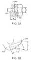
- FIG. 3Adepicts a detailed view of the trailing end of the spacer of FIG. 1 ;
- FIG. 3Bdepicts a detailed view of engaging surfaces of the trailing end of FIG. 3A ;
- FIG. 4Adepicts a view of an insertion tool in accordance with the principles of the present invention
- FIGS. 4B and 4Cdepict a detailed view of the extending portion of the tool of FIG. 4A ;
- FIGS. 5A-5Cdepict a series of views of an insertion tool engaging a spacer in accordance with the principles of the present invention
- FIGS. 6A-6Cdepict an insertion tool and a spacer engaged in three different positions in accordance with the principles of the present invention
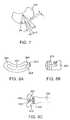
- FIG. 7depicts a detailed view of another trailing end of a spacer.
- FIGS. 8A-8Cdepict an alternative intervertebral spacer.
- FIGS. 9A-9Cdepict another alternative intervertebral spacer and insertion tool.
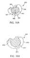
- FIGS. 10A and 10Bdepict a detailed view of different embodiments of the alternative intervertebral spacer of FIGS. 9A and 9B .
- FIGS. 11A and 11Bdepict a detailed view of portions of the insertion tool adapted to operate with the alternative intervertebral spacer of FIGS. 9A and 9B .
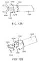
- FIGS. 12A and 12Bdepict other views of the insertion tool of FIGS. 11A and 11B .
- FIG. 1illustrates one typical environment in which intervertebral spacers may be used in accordance with the principles of the present invention.
- the spacer 102is shown on top of a vertebrae body 104 .
- the spinous process 106is located posteriorally with respect to the body 104 .
- the transverse process 108 and the lamina 110are located between the body 104 and the spinous process 106 .
- the second vertebrae body which sits over top of the spacer 102is not shown in FIG. 1 for purposes of clarity. However, as is well known to one of ordinary skill, the spacer 102 is used in this manner to separate two adjacent vertebrae bodies.
- the spacer 102 of FIG. 1is generally kidney-shaped and includes contours that roughly follow the shape of the vertebrae body 104 .
- the posterior portion of the spacer 102is located closer to the spinous process 106 and the anterior portion is located away from the spinous process 106 .
- This orientationis for purposes of providing a consistent frame of reference and is not intended to be interpreted as a limitation of the present invention.
- the spacer 102may be used in a variety of configurations; however, the configuration of FIG. 1 is a typical configuration with the spacer 102 located near the anterior region of the vertebrae body 104 .
- the arrow 112indicates a direction generally referred to, with respect to spacer implants, as transforaminal. This arrow 112 shows the general direction at which the spacer 102 is inserted between two adjacent vertebrae bodies.
- Advantageous attributes of the present inventionallow this direction 112 to widely vary, even during surgery, to allow a surgeon great flexibility in inserting the spacer 102 .
- the orientation of the major axis of the spacer relative to the direction 112may vary as well.
- the spacer 102is designed for insertion in a patient's body, its material is selected to withstand such an environment without deteriorating or harming the patient.
- Exemplary materials useful in these types of circumstancesinclude, but are not limited to, polyether ether ketone, titanium, artificial bone material, and natural bone tissue. Other similar material may be used without departing from the scope of the present invention.
- FIGS. 2A-2Eshow different views of a more detailed depiction of the spacer 102 .
- a number of the features described with reference to these figuresare optional but provide advantages recognized in the art of intervertebral spacers.
- holesmay be present that permit the insertion of bone-grafting material that helps fuse the spacer to adjacent spinal bodies.
- the spacer surfaces which are adjacent vertebrae bodiesmay be rough, or otherwise “keyed”, to improve the mechanical adherence of the spacer to the bodies. In this way, the spacer is less likely to move or shift once it has been surgically implanted.
- FIG. 2Adepicts a view from the superior side of the spacer 102 .
- the spacer 102can be seen as a kidney-shaped cage having a central cavity 201 .
- this cavity 201may be filled with bone-grafting material if desired.
- the spacer 102includes a posterior side 202 and an anterior side 204 . Each of these sides extends from a leading end 206 to a trailing end 208 .
- the top of the posterior side 202is shown having teeth, or ridges, 214 ; while the top of the anterior side 204 is shown with similar teeth 212 .
- teeth 212 , 214are exemplary in nature and can vary in numerous ways, or even be absent, without departing from the scope of the present invention.
- the teeth 212 , 214may be pointed at their peaks and have rounded, pointed, or squared valleys between adjacent peaks.
- the slope of the sides of the teeth 212 , 214may vary as well as the spacing between the teeth 212 , 214 .
- the height of the teeth 212 , 214may vary as well. Because the posterior side 202 and anterior side 204 may be arcuate shaped, the teeth may be spaced variably such that they are closer at their posterior side end that at their anterior side end.
- An exemplary embodiment contemplated within the scope of the present inventionincludes teeth 214 on the posterior side that are spaced about every 10 degrees and have a height of approximately 0.030 inches.
- the sides of adjacent teeth 214adjoin one another at the bottom and form a 90 degree angle with one another.
- shaped teeth 212may be located on the anterior side 204 but spaced at approximately every 5 degrees.
- the trailing end 208includes an exterior surface 210 that has a shape and other features that will be described in more detail later.
- the surface 210includes engaging surfaces shaped to actively engage a complementary-shaped engaging surface of an insertion tool.
- FIG. 2Bis a view of the anterior side 204 and shows a superior side 209 and inferior side 211 . These sides 209 , 211 generally form the top surface and bottom surface of the spacer 102 .
- the teeth 212can also be seen that are on the superior side 209 of the anterior side 204 . Similar teeth 213 may also be present on the inferior side 211 of the anterior side 204 .
- Holes 220 and 222may be used to provide access for bone-grafting material or other substances to be injected into the spacer 102 or may allow for vascularization after implantation. From this view, sloped sides of the 216 and 218 are also visible. These sloped areas of the superior and inferior sides near the leading end 206 are not necessary but may be included in the spacer 102 to assist with insertion of the spacer 102 between adjacent vertebrae bodies.
- FIG. 2Cdepicts a view from the inferior side of the spacer 102 .
- teeth 215may be formed on the inferior side of the posterior side 202 .
- These teeth 215are similar to previously discussed teeth 212 , 214 and the other teeth as well.
- the size, shape, and placement of the teethmay vary greatly without departing from the scope of the present invention. However, in one embodiment, they may be sized similar to the teeth described with respect to FIG. 2A .
- FIG. 2Ddepicts a view of the posterior side 202 of the spacer 102 .
- the leading endis to the right and the trailing end 208 is to the left. From this view, two new features can be seen that have not been previously discussed.
- One channel 228 and another channel 227are shown in this view.
- the channel 228has a height that is greater than its width while the channel 227 has a height that is smaller than that of the channel 228 . Both of these channels have an opening exposed to the surface near the point where the trailing end 208 joins the posterior side 202 .
- the channel 227extends a significant portion around the circumference of the trailing end, substantially centered between the inferior side 211 and superior side 209 , thereby exposing a portion of the interior of the other channel 228 .
- FIG. 2Edepicts a view from the trailing end of the spacer 102 and shows one arrangement of the inferior side 211 and superior side 209 . While the posterior side 202 and the anterior side 204 may be the same height, this design constraint is not necessary.
- the spacer of FIG. 2Eincludes an anterior side 204 that is taller than the posterior side 202 . This causes the superior side 209 to slope upwardly from the posterior side 202 to the anterior side 204 . Because, the anterior side also extends below the bottom of the posterior side 202 , the inferior side 211 also slopes; in this instance it slopes downwardly from the posterior side 202 to the anterior side 204 .
- either one of the superior or inferior sidescould be arranged to have no slope, or an opposite slope, by sizing the anterior and posterior sides accordingly.
- the slope of the superior and inferior sidesdoes not necessarily have to be a constant value but may vary over its expanse. If the slope is constant, one exemplary value for that angle, ⁇ , is about 8 degrees.
- the relative size of the spacer or height Hcan vary according to its intended use.
- the spacing between vertebraemay vary based on patient size and may also vary based on which region of the spine is being accessed.
- the nominal height, H, of the spacermay vary so as to provide a surgeon with a variety of different sized spacers.
- Exemplary spacer sizes that will accommodate most adult human situationsinclude the following sizes. However, other sizes may be considered without departing from the scope of the present invention.
- FIG. 2Fdepicts a view of the spacer similar to that of FIG. 2A .
- a number of the previously described featureshave been omitted so as not to obscure the axis 250 that extends in a direction substantially along the length of the spacer, L 1 .
- this axis 250is labeled the major axis of the spacer 102 .
- one exemplary spacermay have a length L 1 of approximately 1.06 inches and a width W of about 0.45 inches, while the cavity 201 may have a length L 2 of about 0.74 inches. These dimensions are provided as examples only of sizes that advantageously will fit many adult human patients of various sizes.
- FIGS. 3A and 3Bdepict portions of the trailing end 208 of the spacer 102 that interact with such an insertion tool. These features have been described earlier as the channels 227 and 228 .
- the view of FIG. 3Ais a cut-away view taken along the line A-A of FIG. 2A . This view shows the cross-sectional shape of the two channels 227 and 228 . These channels 227 and 228 are shaped, sized and located to accept a portion of the insertion tool that extends outwardly from the insertion tool.
- the following dimensionsprovide channels that are appropriate for these spacers.
- these examples of channel sizesare merely exemplary in nature and other sized channels may be provided without departing from the scope of the present invention.
- engaging surfaces 210include a plurality of surfaces arranged radially along the exterior circumference of the trailing end 208 .
- complementary-shaped engaging surfaces on an insertion toolmay engage different groups of these surfaces 210 so that an angle formed between the tool and the spacer may vary based on which of the engaging surfaces 210 are aligned with the complementary surfaces of the tool.
- FIGS. 4A-4Cdepict an insertion tool 400 and its details.
- FIGS. 4B and 4Cdepict a detailed view of the region 402 in FIG. 4A .
- the insertion tool 400includes a handle portion 404 and a shaft 406 extending towards an end distant from the handle 404 .
- This distal endis generally referred to as the insertion end of the tool 400 and includes a surface 410 shaped to engage the features 210 on the trailing end of the spacer 102 .
- the insertion endalso includes an extending portion 408 that extends outwardly from the handle 404 of the tool.
- pis approximately 1.13 inches
- nis 5.4 inches
- mis 7.4 inches
- the handle 404operates to move the surface 410 towards or away from the extending portion 408 .
- thismay be accomplished by moving either the extending portion 408 or the surface 410 ; in either case the same relative motion is accomplished.
- One exemplary techniqueis for the extending portion 408 to be attached to a shaft that is located within the shaft 406 . Twisting the handle 404 in one direction causes the outside shaft 406 to move relative to the inner shaft (not shown). This movement causes the surface 410 to move towards the extending portion 408 . Rotation of the handle 404 in the opposite direction causes opposite movement of the outside shaft 406 resulting in motion of the surface 410 away from the extending portion 408 .
- the inner shaftincludes a stop 409 that extends through an opening 407 so as to align the shafts and restrict the extent of movement of the outside shaft 406 in either direction of travel.
- FIG. 4Bdepicts a detailed top view of the distal end of the insertion tool 400 . From this view, the engaging features 412 of the surface 410 are visible. These features 412 are shaped to engage the similarly shaped features 210 on the trailing end of the space 102 . The detailed side view of FIG. 4C obscures these features 412 but depicts the extending portion 408 from a perspective that allows exemplary measurements to be provided.
- the measurements provided hereinare exemplary in nature and are intended to match to the spacer sizes that have been previously described.
- One of ordinary skillwill recognize that different sized spacers 102 and different sized channels 227 , 228 will result in different sized extending portions 408 .
- Exemplary measurementsinclude:
- the portion 422 of the extending portion 408is inserted into and fits within the channel 227 of the spacer 102 .
- the other portion 420is inserted within the other channel 228 .
- the extending portion 408securely engages the spacer 102 because the portion 420 is too large to pass through the channel 227 .
- the surface 410may be moved so as to be positioned closer to the extending portion 408 . More particularly, the surface 410 is moved in this direction so that the engaging features 412 engage complementary-shaped features 210 on the spacer's trailing end 208 .
- the insertion tool 400 and the spacer 102are securely, but releasably, fastened to one another such that relative motion between the two is prevented.
- the engaging featuresare not actively engaged, the tool 400 and the spacer 102 are still securely engaged (through operation of the extending portion 408 ); however, relative motion is permitted because the spacer 102 can rotate around the portion 420 of the extending portion 408 .
- This rotationallows the spacer 102 and the tool to be repositioned so that the engaging features 412 of the tool 400 can be aligned to engage different complementary-shaped features 210 of the spacer.
- an angle between the major axis 405 of the tool 400 and the spacer's 250can be changed even while the extending portion 408 is disposed within the spacer 102 .
- FIGS. 5A-5Cdepict the series of events just described.
- the spacer 102 of these figuresmay include all the features previously described with relation to earlier figures. However, these features have not been explicitly depicted so as not to obscure the events shown in FIGS. 5A-5C .
- the tool 400has its extending portion 408 extended as it approaches the trailing end 208 of the spacer 102 .
- the channels 227 , 228 and the engaging features 210are shown as well as the tool's engaging features 412 .
- the spacer 102may already be placed in a patient's body at this time by some other means or may be outside of the patient's body being prepared for insertion with the tool 400 .
- FIG. 5Bthe portion 420 of the extending portion 408 has been inserted in the channel 228 and the other portion 422 has been inserted into the channel 227 and extends outwardly from the spacer 102 .
- the surface 410 of the toolis moved in a relative direction towards the spacer 102 so that the engaging surfaces 210 and 412 actively engage and couple with one another.
- These complementary-shaped engaging surfacesare depicted in these figures as pointed teeth. However, other shapes that actively engage one another may be used as well. For example, other shaped teeth may be used such as cog-shaped teeth as well as rounded over teeth may be used as well.
- FIGS. 6A-6Cdepict the alignment of the tool 400 and the spacer 102 in three different positions.
- the different positionsrelate to which of the engaging features 210 of the spacer 102 align with the engaging features 412 of the tool.
- these engaging features 210 , 412will be referred to as “teeth” although other shapes are contemplated as well.
- FIG. 6Athe teeth of the tool engage the teeth of the spacer 102 that are closer to the anterior side 204 .
- FIG. 6Cwhere the teeth closer to the posterior side 202 are engaged.
- FIG. 6Bdepicts a position between these two extremes.
- the number of teeth 210 around the trailing end of the spacer 102is a factor in the number of different possible positions in which the tool 400 and the spacer 102 can be engaged.
- the teeth 210may extend for an arc that measures about +/ ⁇ 35 degrees from the center of the trailing end 208 . Other ranges, both smaller and larger, are contemplated as well.
- the teeth 412 on the toolare preferably fewer in number than those 210 on the spacer 102 .
- the spread of the teeth 412may be less as well on the tool 400 , such as about +/ ⁇ 20 degrees from the center of the tool's surface 410 .
- the tool 400may be moved between the different positions of FIGS. 6A-6C while the portion 420 remains within the channel 228 .
- the surface 410is simply moved away from the spacer 102 so that the engaging surfaces 210 , 412 are disengaged and then the major axis 405 of the tool 400 may be rotated relative to the spacer 102 .
- the tool 400 and the spacer 102may remain securely attached to one another, while still allowing realigning of the angle formed between the major axis 250 of the spacer 102 and that of the tool 400 .
- the engaging surfaces 210 , 412may be re-engaged in a secure manner by moving the surface 410 towards the spacer 102 .
- a surgeonmay alter the insertion angle of the spacer 102 during surgery in numerous and various ways to account for possible variations and conditions that might arise during surgery. Even though such flexibility is provided, the tool 400 and the spacer 102 remain fastened together so that re-securing the two relative to one another, after an adjustment, may be easily accomplished without difficulty or fear of unwanted separation.
- FIG. 7depicts a detailed view of gear-shaped teeth along with exemplary dimensions for a spacer.
- the trailing end 208 depicted in FIG. 7includes, for example 3 gear-shaped teeth.
- 3 gear-shaped teethOne of ordinary skill will recognize that different shaped teeth may be used as well as differently sized teeth.
- Some of the dimensions that define teethare the angles formed by their adjacent sides, the sizes of the valleys between the teeth, the height of the teeth, and the width of the teeth.
- the table belowprovides exemplary dimensions for teeth sized to fit the previously described spacers for a typical human patient.
- FIGS. 8A-8Cdepict an alternative spacer 802 that performs functionally equivalent to the previously described spacer 102 .
- the alternative spacer 802includes a trailing end 808 that includes engaging features 810 .
- the engaging features 810are substantially the same as those described previously.
- the trailing end 808includes a through hole 804 that extends through from the exterior surface of the trailing end 808 to the central cavity 801 .
- the shape of the hole 804shown in FIG.
- the engaging surfaces 810 and 412engage in a manner similar to that already described while one portion 422 of the extending portion 408 resides in the through hole 804 and the other portion 420 of the extending portion 408 is trapped within the cavity 801 of the spacer 802 .
- the angle of the tool 400 and the spacer 802may be changed while the portion 420 remains in position. This is accomplished merely by disengaging the engaging features of the tool 400 and the spacer 802 and repositioning the tool 400 relative to the spacer 802 .
- FIGS. 9A-9Cdepict another alternative intervertebral spacer and insertion tool.
- the trailing end 908 of the spacer 902has a partially cylindrical channel that is shaped to interact with the insertion tool 950 .
- the channelcan also be considered as semicircular in nature as well.
- FIG. 9Aa view from the top of the spacer 902 , the channel is shown as dotted region 901 .
- the side view of FIG. 9Balso illustrates the placement of the channel 901 relative to the trailing end 908 having engaging teeth 910 . While it is not necessary to form the channel 901 as a complete cylinder, or circle, encompassing an entire 360 degrees, the channel 901 advantageously has an arcuate circumference that encompasses at least 180 degrees.
- the channel 901is located between an upper edge 907 and a lower edge 905 of the trailing end 908 of the implant 902 .
- one exemplary heightmay be approximately 0.135 inches although other sizes are contemplated as well.
- the insertion tool 950 of FIG. 9Cincludes engaging features 952 similar to those previously described but includes a different extending portion having two opposing arms 954 and 956 .
- These arms 954 , 956are shaped to be inserted within the channel 901 to grip the exterior cylindrical surface of the channel 901 . Because of the arcuate range of the channel 901 , the arms 954 , 956 can securely grip within the channel at a number of different positions.
- the arms 954may be formed of a resilient plastic or metal that is well-suited for the intended surgical environment. Also, the arms 956 , 954 have, respectively, angled portion 958 , 960 that cause the arms 954 , 956 to be forced together when the engaging features 952 are moved toward the trailing end of a spacer.
- the relative distance between the arms 954 , 956may be designed such that the engaging features 952 and 910 may be slightly separated from active engagement while the arms 954 , 956 remain in contact with the external surface of the channel 901 . In this manner, the position of the tool 950 relative to the spacer 902 may be changed while the two remain in relatively secure engagement.
- FIGS. 10A and 10Boffer a more detailed view of the region 903 of FIG. 9A .
- the trailing end 908 of the implant 902has a channel 966 that is formed around a cylindrical or semicircular portion 962 .
- the radius 968 of the semicircular portion 962may, for example, be approximately 0.11 inches and the outside radius 967 of the trailing end 908 may, for example, be larger such as approximately 0.1618 inches.
- the channel 966has a thickness that varies because of these different radii 967 , 968 .
- the teeth 964 , or engaging portionoperated to securely engage complimentary features of the insertion tool (not shown) so that the insertion tool and the spacer may be securely engaged at any of a plurality of different positions and angles.
- the semicircular portion 962terminates at two ends that are separated by a distance 969 .
- the distance 969may be, for example, approximately 0.1850 inches. This distance depends on the arcuate circumference of the semicircular portion 962 which may vary anywhere from 180 to about 250 degrees.
- FIG. 10Bdepicts an alternative detailed view of region 903 that has many similarities to FIG. 10A such as the channel 970 and the semicircular portion 972 .
- the engaging surfaces 974may be cog-like teeth rather than the sharp teeth 964 of FIG. 10A .
- the semicircular portion 972does not necessarily have to have a uniform radius of curvature but may also include a portion 976 that has a different radius of curvature. The portion 976 may be present on both ends of the portion 972 or just at a single end.
- FIG. 11Adepicts a detailed view of an insertion tool of FIG. 9C that is adapted to securely engage the spacer of FIGS. 9A and 9B at a plurality of different positions and angles.
- FIG. 11Adepicts the opposing arms that are adapted to engage the channel of the spacer while
- FIG. 11Bdepicts the engaging end of the insertion tool that has an engaging surface that includes engaging features that match complimentary features on the upper and lower edges of the trailing end of the spacer.
- the opposing arms 1102 , 1104are resiliently arranged so that they separate from one another when extender from the tool 950 and squeeze towards one another when retracted into the tool 950 .
- the arms 1102 , 1104are shaped and sized to securely fit within the channel 901 of the spacer 902 .
- the features of the opposing arms 1102 , 1104may have the following dimensions.
- the portion 1202 of the tool 950is the external part of the end of the tool through which the opposing arms 1102 , 1104 extend.
- a first portion 1202that engages the trailing end 908 of the spacer 902 that eventually merges into a shaft portion 1204 of the insertion tool.
- the first portion 1202may, for example, have a length of approximately 0.30 inches although this length may, of course, be larger or smaller as well.
- the first portion 1202is shaped to fit around the trailing end 908 of the spacer 902 and, therefore, is curved in nature to match the curvature of the spacer 902 .
- the first portion 1202can converge outwardly at a rate 1206 of 11 degrees from a centerline such that the curvature of the first portion 1202 can accommodate the spacer 902 .
- the engaging features 1210that are configured to engage complimentary features 910 on the upper edge 907 and lower edge 905 of the spacer 902 .
- the angle of engagement between the tool and the spacercan vary. In this way, the tool and the spacer may securely engage one another at one of many different, selectable engagement angles.
- the height of the engaging surfaces 1210may, for example, be approximately 0.023 inches.
- the tool 950may be positioned such that the opposing arms 1102 , 1104 are located within the channel 966 around the semicircular portion 962 . As the first portion is extended (relative to the opposing arms) towards the spacer 902 , the opposing arms are forced together so that they grip the exterior surface of the semicircular portion 962 . Even though the tool 950 and spacer 902 are somewhat securely engaged at this point, the tool 950 can still be twisted relative to the spacer 902 because the mechanical force applied to the tool 950 by a doctor can overcome the frictional engagement between the opposing arms 1102 , 1104 and the channel 966 .
- the angle between the tool 950 and the spacer 902can be adjusted even though the tool 950 and spacer 902 are connected in a manner in which they will not inadvertently separate.
- the engaging surfaces 1210will engage complementary surfaces 910 on the spacer 902 .
- the angle between the tool 950 and the spacer 902will be fixed in one of the many different selectable angles that are possible.
- the first portion 1202is refracted from the spacer so that the engaging surfaces of the tool and spacer disengage.
- the tool 950can once again be twisted relative to the spacer 902 so that when they are reengaged they are at a different angle relative to one another.
- FIGS. 12A and 12Bdepict other views of the insertion tool of FIGS. 11A and 11B that help highlight some of the features of this insertion tool.
- the opposing arms 1102 , 1104 in an unbiased positione.g., FIGS. 12A and 12B
- these armsare pressed towards one another in order to grip the spacer.
- these arms 1102 , 1104are shaped to be inserted in the channel of the spacer and then tighten around that cylindrical surface.
- the tool of FIGS. 12A and 12Brelies on features of the external portion 1202 to press the opposing arms 1102 , 1104 together.
- the external portion 1202includes wings, or arms, 1220 , 1222 that are shaped so that they contact the opposing arms 1102 , 1104 and squeeze these arms 1102 , 1104 together.
- the opposing arms 1102 , 1104are withdrawn back towards the external portion 1202 , the outside surfaces of the arms 1102 , 1104 come in contact with a respective wing 1220 , 1222 which forces the opposing arms 1102 , 1104 in a direction towards one another.
- the opposing arms 1102 , 1104are extended outwardly from the external portion 1202 , they are free to expand once they clear the wings 1220 , 1222 .
Landscapes
- Health & Medical Sciences (AREA)
- Engineering & Computer Science (AREA)
- Biomedical Technology (AREA)
- Orthopedic Medicine & Surgery (AREA)
- Transplantation (AREA)
- Neurology (AREA)
- Heart & Thoracic Surgery (AREA)
- Oral & Maxillofacial Surgery (AREA)
- Cardiology (AREA)
- Vascular Medicine (AREA)
- Life Sciences & Earth Sciences (AREA)
- Animal Behavior & Ethology (AREA)
- General Health & Medical Sciences (AREA)
- Public Health (AREA)
- Veterinary Medicine (AREA)
- Physical Education & Sports Medicine (AREA)
- Prostheses (AREA)
Abstract
Description
| H (inches) |
| .278 |
| .315 |
| .354 |
| .394 |
| .433 |
| .472 |
| .512 |
| .561 |
| .591 |
| .630 |
| .668 |
| .709 |
| Dimension | Size (inches) | ||
| a | .065 | ||
| b | .180 | ||
| c | .750 | ||
| d | .173 | ||
| e | .265 | ||
| f | .253 | ||
| Dimension | Size (inches) | ||
| u | 0.13 | ||
| v | 0.18 | ||
| x | 0.06 | ||
| y | 0.04 | ||
| z | 0.16 | ||
| Dimension | Size | ||
| q | .023 inches | ||
| r | 40 degrees | ||
| s | .030 inches | ||
| t | 25 degrees | ||
| Size | |||
| 1106 | Radius of .1117 | ||
| 1108 | .125 | ||
| 1109 | .110 | ||
| 1110 | .187 inches | ||
These dimensions are exemplary in nature and are provided merely as a specific example of one embodiment of the variety of different spacers and insertion tools contemplated within the scope of the present invention.
Claims (25)
Priority Applications (1)
| Application Number | Priority Date | Filing Date | Title |
|---|---|---|---|
| US13/543,672US8673012B2 (en) | 2006-03-08 | 2012-07-06 | Intervertebral spacer and insertion tool providing multiple angles of insertion |
Applications Claiming Priority (3)
| Application Number | Priority Date | Filing Date | Title |
|---|---|---|---|
| US11/371,539US20070213826A1 (en) | 2006-03-08 | 2006-03-08 | Intervertebral spacer and insertion tool providing multiple angles of insertion |
| US11/371,453US20070213737A1 (en) | 2006-03-08 | 2006-03-08 | Insertion tool for an intervertebral spacer providing multiple angles of insertion |
| US13/543,672US8673012B2 (en) | 2006-03-08 | 2012-07-06 | Intervertebral spacer and insertion tool providing multiple angles of insertion |
Related Parent Applications (1)
| Application Number | Title | Priority Date | Filing Date |
|---|---|---|---|
| US11/371,539ContinuationUS20070213826A1 (en) | 2006-03-08 | 2006-03-08 | Intervertebral spacer and insertion tool providing multiple angles of insertion |
Publications (2)
| Publication Number | Publication Date |
|---|---|
| US20120277877A1 US20120277877A1 (en) | 2012-11-01 |
| US8673012B2true US8673012B2 (en) | 2014-03-18 |
Family
ID=46325300
Family Applications (2)
| Application Number | Title | Priority Date | Filing Date |
|---|---|---|---|
| US11/371,539AbandonedUS20070213826A1 (en) | 2006-03-08 | 2006-03-08 | Intervertebral spacer and insertion tool providing multiple angles of insertion |
| US13/543,672ActiveUS8673012B2 (en) | 2006-03-08 | 2012-07-06 | Intervertebral spacer and insertion tool providing multiple angles of insertion |
Family Applications Before (1)
| Application Number | Title | Priority Date | Filing Date |
|---|---|---|---|
| US11/371,539AbandonedUS20070213826A1 (en) | 2006-03-08 | 2006-03-08 | Intervertebral spacer and insertion tool providing multiple angles of insertion |
Country Status (1)
| Country | Link |
|---|---|
| US (2) | US20070213826A1 (en) |
Cited By (10)
| Publication number | Priority date | Publication date | Assignee | Title |
|---|---|---|---|---|
| US20130110247A1 (en)* | 2011-11-01 | 2013-05-02 | Amedica Corporation | Implants with a Connectable Insert and Related Systems and Methods |
| US20140058518A1 (en)* | 2008-10-13 | 2014-02-27 | Marcin Niemiec | Articulating Spacer |
| US9216096B2 (en) | 2010-03-16 | 2015-12-22 | Pinnacle Spine Group, Llc | Intervertebral implants and related tools |
| US9380932B1 (en) | 2011-11-02 | 2016-07-05 | Pinnacle Spine Group, Llc | Retractor devices for minimally invasive access to the spine |
| EP3135257A2 (en) | 2015-08-26 | 2017-03-01 | Biedermann Technologies GmbH & Co. KG | Intervertebral implant and device for inserting an intervertebral implant |
| US10004609B2 (en) | 2016-09-23 | 2018-06-26 | Warsaw Orthopedic, Inc. | Surgical instrument and method |
| US10070970B2 (en) | 2013-03-14 | 2018-09-11 | Pinnacle Spine Group, Llc | Interbody implants and graft delivery systems |
| US10478313B1 (en) | 2014-01-10 | 2019-11-19 | Nuvasive, Inc. | Spinal fusion implant and related methods |
| US11241318B2 (en) | 2019-09-18 | 2022-02-08 | Biedermann Technologies Gmbh & Co. Kg | Intervertebral implant and insertion device therefor |
| US12208016B2 (en) | 2020-09-22 | 2025-01-28 | Biedermann Technologies Gmbh & Co. Kg | Implant, insertion device, and plate assembly |
Families Citing this family (81)
| Publication number | Priority date | Publication date | Assignee | Title |
|---|---|---|---|---|
| US20060229627A1 (en) | 2004-10-29 | 2006-10-12 | Hunt Margaret M | Variable angle spinal surgery instrument |
| US11096796B2 (en)* | 2005-05-06 | 2021-08-24 | Titan Spine, Llc | Interbody spinal implant having a roughened surface topography on one or more internal surfaces |
| US20070213737A1 (en)* | 2006-03-08 | 2007-09-13 | Seaspine, Inc. | Insertion tool for an intervertebral spacer providing multiple angles of insertion |
| US8409290B2 (en)* | 2006-03-08 | 2013-04-02 | Seaspine, Inc. | Interbody device for spinal applications |
| US20070213826A1 (en) | 2006-03-08 | 2007-09-13 | Seaspine, Inc. | Intervertebral spacer and insertion tool providing multiple angles of insertion |
| US8157845B2 (en)* | 2006-03-22 | 2012-04-17 | Beacon Biomedical, Llc | Pivotable vetrebral spacer |
| US9345587B2 (en) | 2006-03-22 | 2016-05-24 | Beacon Biomedical, Llc | Pivotal lateral cage and method of insertion |
| US8454621B2 (en)* | 2006-09-19 | 2013-06-04 | Warsaw Orthopedic, Inc. | Instruments and methods for spinal implant revision |
| WO2008070863A2 (en) | 2006-12-07 | 2008-06-12 | Interventional Spine, Inc. | Intervertebral implant |
| US8900307B2 (en) | 2007-06-26 | 2014-12-02 | DePuy Synthes Products, LLC | Highly lordosed fusion cage |
| WO2009040840A1 (en)* | 2007-09-28 | 2009-04-02 | Sintea Biotech S.P.A. | Intersomatic cage, pliers for intersomatic cage, kit for insertion of an intersomatic cage |
| DE102007052173B4 (en)* | 2007-10-30 | 2012-01-12 | Kilian Kraus | Handling tool for a medical implant |
| EP2237748B1 (en) | 2008-01-17 | 2012-09-05 | Synthes GmbH | An expandable intervertebral implant |
| US8088163B1 (en) | 2008-02-06 | 2012-01-03 | Kleiner Jeffrey B | Tools and methods for spinal fusion |
| US8216317B2 (en) | 2008-03-31 | 2012-07-10 | Stryker Spine | Spinal implant apparatus and methods |
| US8936641B2 (en) | 2008-04-05 | 2015-01-20 | DePuy Synthes Products, LLC | Expandable intervertebral implant |
| US20210378834A1 (en) | 2008-05-22 | 2021-12-09 | Spinal Surgical Strategies, Inc., A Nevada Corporation D/B/A Kleiner Device Labs | Spinal fusion cage system with inserter |
| DE102008045174B4 (en)* | 2008-08-30 | 2018-12-20 | Aesculap Ag | Device for implanting an intervertebral implant |
| US8147554B2 (en)* | 2008-10-13 | 2012-04-03 | Globus Medical, Inc. | Intervertebral spacer |
| US8366748B2 (en) | 2008-12-05 | 2013-02-05 | Kleiner Jeffrey | Apparatus and method of spinal implant and fusion |
| AU2009329873A1 (en) | 2008-12-26 | 2011-11-03 | Scott Spann | Minimally-invasive retroperitoneal lateral approach for spinal surgery |
| US9247943B1 (en)* | 2009-02-06 | 2016-02-02 | Kleiner Intellectual Property, Llc | Devices and methods for preparing an intervertebral workspace |
| US9526620B2 (en) | 2009-03-30 | 2016-12-27 | DePuy Synthes Products, Inc. | Zero profile spinal fusion cage |
| US8287597B1 (en) | 2009-04-16 | 2012-10-16 | Nuvasive, Inc. | Method and apparatus for performing spine surgery |
| US9050194B2 (en) | 2009-05-06 | 2015-06-09 | Stryker Spine | Expandable spinal implant apparatus and method of use |
| ES2563172T3 (en) | 2009-07-09 | 2016-03-11 | R Tree Innovations, Llc | Flexible intersomatic implant |
| US20110029083A1 (en)* | 2009-07-31 | 2011-02-03 | Warsaw Orthopedic, Inc. | Flexible Spinal Implant |
| US8906028B2 (en) | 2009-09-18 | 2014-12-09 | Spinal Surgical Strategies, Llc | Bone graft delivery device and method of using the same |
| US10245159B1 (en) | 2009-09-18 | 2019-04-02 | Spinal Surgical Strategies, Llc | Bone graft delivery system and method for using same |
| US20170238984A1 (en) | 2009-09-18 | 2017-08-24 | Spinal Surgical Strategies, Llc | Bone graft delivery device with positioning handle |
| USD750249S1 (en) | 2014-10-20 | 2016-02-23 | Spinal Surgical Strategies, Llc | Expandable fusion cage |
| US10973656B2 (en) | 2009-09-18 | 2021-04-13 | Spinal Surgical Strategies, Inc. | Bone graft delivery system and method for using same |
| US9629729B2 (en) | 2009-09-18 | 2017-04-25 | Spinal Surgical Strategies, Llc | Biological delivery system with adaptable fusion cage interface |
| US9186193B2 (en) | 2009-09-18 | 2015-11-17 | Spinal Surgical Strategies, Llc | Fusion cage with combined biological delivery system |
| US9173694B2 (en) | 2009-09-18 | 2015-11-03 | Spinal Surgical Strategies, Llc | Fusion cage with combined biological delivery system |
| USD723682S1 (en) | 2013-05-03 | 2015-03-03 | Spinal Surgical Strategies, Llc | Bone graft delivery tool |
| US9060877B2 (en) | 2009-09-18 | 2015-06-23 | Spinal Surgical Strategies, Llc | Fusion cage with combined biological delivery system |
| US8685031B2 (en) | 2009-09-18 | 2014-04-01 | Spinal Surgical Strategies, Llc | Bone graft delivery system |
| US9668882B2 (en)* | 2009-10-02 | 2017-06-06 | Amedica Corporation | Biomedical implant inserters and related apparatus, systems, and methods |
| US8821578B2 (en)* | 2009-10-02 | 2014-09-02 | U.S. Spine, Inc. | Intervertebral implant device for a posterior interbody fusion surgical procedure |
| US9028553B2 (en) | 2009-11-05 | 2015-05-12 | DePuy Synthes Products, Inc. | Self-pivoting spinal implant and associated instrumentation |
| US9393129B2 (en) | 2009-12-10 | 2016-07-19 | DePuy Synthes Products, Inc. | Bellows-like expandable interbody fusion cage |
| US8956414B2 (en)* | 2010-04-21 | 2015-02-17 | Spinecraft, LLC | Intervertebral body implant, instrument and method |
| US8979860B2 (en) | 2010-06-24 | 2015-03-17 | DePuy Synthes Products. LLC | Enhanced cage insertion device |
| US9907560B2 (en) | 2010-06-24 | 2018-03-06 | DePuy Synthes Products, Inc. | Flexible vertebral body shavers |
| US8623091B2 (en) | 2010-06-29 | 2014-01-07 | DePuy Synthes Products, LLC | Distractible intervertebral implant |
| US8603175B2 (en) | 2010-09-30 | 2013-12-10 | Stryker Spine | Method of inserting surgical implant with guiding rail |
| US8425529B2 (en) | 2010-09-30 | 2013-04-23 | Stryker Spine | Instrument for inserting surgical implant with guiding rail |
| US8858637B2 (en)* | 2010-09-30 | 2014-10-14 | Stryker Spine | Surgical implant with guiding rail |
| US9402732B2 (en) | 2010-10-11 | 2016-08-02 | DePuy Synthes Products, Inc. | Expandable interspinous process spacer implant |
| EP3485851B1 (en) | 2011-03-22 | 2021-08-25 | DePuy Synthes Products, LLC | Universal trial for lateral cages |
| EP2535021B1 (en)* | 2011-06-14 | 2015-10-14 | Biedermann Technologies GmbH & Co. KG | Intervertebral implant |
| ES2555065T3 (en) | 2011-06-14 | 2015-12-28 | Biedermann Technologies Gmbh & Co. Kg | Device for inserting an intervertebral implant into a body and system comprising an intervertebral implant and a device for inserting it |
| US9220607B2 (en)* | 2011-10-28 | 2015-12-29 | Warsaw Oorthopedic, Inc. | Pivotable interbody implant system |
| US9226764B2 (en) | 2012-03-06 | 2016-01-05 | DePuy Synthes Products, Inc. | Conformable soft tissue removal instruments |
| CA2880825C (en) | 2012-03-20 | 2021-03-16 | Titan Spine, Llc | Friction-fit spinal endplate and endplate-preserving method |
| US10022245B2 (en)* | 2012-12-17 | 2018-07-17 | DePuy Synthes Products, Inc. | Polyaxial articulating instrument |
| US9717601B2 (en) | 2013-02-28 | 2017-08-01 | DePuy Synthes Products, Inc. | Expandable intervertebral implant, system, kit and method |
| US9522070B2 (en) | 2013-03-07 | 2016-12-20 | Interventional Spine, Inc. | Intervertebral implant |
| DE102013004964B4 (en)* | 2013-03-22 | 2016-11-03 | Joimax Gmbh | Instrument set and method for inserting a basket into the disc space between two vertebral bodies |
| US9526629B2 (en) | 2013-09-27 | 2016-12-27 | Amedica Corporation | Spinal implants and related instruments and methods |
| US11426290B2 (en) | 2015-03-06 | 2022-08-30 | DePuy Synthes Products, Inc. | Expandable intervertebral implant, system, kit and method |
| USD797290S1 (en) | 2015-10-19 | 2017-09-12 | Spinal Surgical Strategies, Llc | Bone graft delivery tool |
| US9895235B2 (en)* | 2015-12-18 | 2018-02-20 | Warsaw Orthopedic, Inc. | Spinal implant system and method |
| US11510788B2 (en) | 2016-06-28 | 2022-11-29 | Eit Emerging Implant Technologies Gmbh | Expandable, angularly adjustable intervertebral cages |
| EP3474784A2 (en) | 2016-06-28 | 2019-05-01 | Eit Emerging Implant Technologies GmbH | Expandable and angularly adjustable intervertebral cages with articulating joint |
| US10716553B2 (en) | 2017-04-19 | 2020-07-21 | Pantheon Spinal, Llc | Spine surgery retractor system and related methods |
| US10398563B2 (en) | 2017-05-08 | 2019-09-03 | Medos International Sarl | Expandable cage |
| US11344424B2 (en) | 2017-06-14 | 2022-05-31 | Medos International Sarl | Expandable intervertebral implant and related methods |
| US10966843B2 (en) | 2017-07-18 | 2021-04-06 | DePuy Synthes Products, Inc. | Implant inserters and related methods |
| US11045331B2 (en) | 2017-08-14 | 2021-06-29 | DePuy Synthes Products, Inc. | Intervertebral implant inserters and related methods |
| WO2019051260A1 (en) | 2017-09-08 | 2019-03-14 | Pioneer Surgical Technology, Inc. | Intervertebral implants, instruments, and methods |
| USD907771S1 (en) | 2017-10-09 | 2021-01-12 | Pioneer Surgical Technology, Inc. | Intervertebral implant |
| US10973658B2 (en) | 2017-11-27 | 2021-04-13 | Titan Spine, Inc. | Rotating implant and associated instrumentation |
| US11135070B2 (en) | 2018-02-14 | 2021-10-05 | Titan Spine, Inc. | Modular adjustable corpectomy cage |
| US11446156B2 (en) | 2018-10-25 | 2022-09-20 | Medos International Sarl | Expandable intervertebral implant, inserter instrument, and related methods |
| US11039931B2 (en)* | 2019-02-01 | 2021-06-22 | Globus Medical, Inc. | Intervertebral spinal implant |
| US11426286B2 (en) | 2020-03-06 | 2022-08-30 | Eit Emerging Implant Technologies Gmbh | Expandable intervertebral implant |
| US11850160B2 (en) | 2021-03-26 | 2023-12-26 | Medos International Sarl | Expandable lordotic intervertebral fusion cage |
| US11752009B2 (en) | 2021-04-06 | 2023-09-12 | Medos International Sarl | Expandable intervertebral fusion cage |
| US12090064B2 (en) | 2022-03-01 | 2024-09-17 | Medos International Sarl | Stabilization members for expandable intervertebral implants, and related systems and methods |
Citations (69)
| Publication number | Priority date | Publication date | Assignee | Title |
|---|---|---|---|---|
| DE2263842A1 (en) | 1972-12-28 | 1974-07-04 | Hoffmann Daimler Siegfried Dr | DISC PROTHESIS |
| US5071437A (en) | 1989-02-15 | 1991-12-10 | Acromed Corporation | Artificial disc |
| US5431658A (en) | 1994-02-14 | 1995-07-11 | Moskovich; Ronald | Facilitator for vertebrae grafts and prostheses |
| US5676701A (en) | 1993-01-14 | 1997-10-14 | Smith & Nephew, Inc. | Low wear artificial spinal disc |
| US5733290A (en) | 1995-12-21 | 1998-03-31 | Johnson & Johnson Professional, Inc. | Quick-release tibial alignment handle |
| US5755796A (en) | 1996-06-06 | 1998-05-26 | Ibo; Ivo | Prosthesis of the cervical intervertebralis disk |
| US5899941A (en) | 1997-12-09 | 1999-05-04 | Chubu Bearing Kabushiki Kaisha | Artificial intervertebral disk |
| US6033438A (en) | 1997-06-03 | 2000-03-07 | Sdgi Holdings, Inc. | Open intervertebral spacer |
| US6113637A (en) | 1998-10-22 | 2000-09-05 | Sofamor Danek Holdings, Inc. | Artificial intervertebral joint permitting translational and rotational motion |
| US6113638A (en) | 1999-02-26 | 2000-09-05 | Williams; Lytton A. | Method and apparatus for intervertebral implant anchorage |
| US6193757B1 (en) | 1998-10-29 | 2001-02-27 | Sdgi Holdings, Inc. | Expandable intervertebral spacers |
| US6206924B1 (en) | 1999-10-20 | 2001-03-27 | Interpore Cross Internat | Three-dimensional geometric bio-compatible porous engineered structure for use as a bone mass replacement or fusion augmentation device |
| US6235059B1 (en) | 1996-04-03 | 2001-05-22 | Scient'x (Societe A Responsabilite Limitee) | Intersomatic setting and fusion system |
| US20010020170A1 (en) | 1997-01-02 | 2001-09-06 | Zucherman James F. | Spinal implants, insertion instruments, and methods of use |
| US6319257B1 (en) | 1999-12-20 | 2001-11-20 | Kinamed, Inc. | Inserter assembly |
| US6368354B2 (en) | 1999-10-07 | 2002-04-09 | Exactech, Inc. | Acetabular bearing assembly for total hip joints |
| US6368350B1 (en) | 1999-03-11 | 2002-04-09 | Sulzer Spine-Tech Inc. | Intervertebral disc prosthesis and method |
| US6478801B1 (en) | 2001-07-16 | 2002-11-12 | Third Millennium Engineering, Llc | Insertion tool for use with tapered trial intervertebral distraction spacers |
| US20030045939A1 (en) | 2001-08-24 | 2003-03-06 | Simon Casutt | Artificial intervertebral disc |
| US20030069586A1 (en) | 2001-07-16 | 2003-04-10 | Errico Joseph P. | Instrumentation and methods for use in implanting an artificial intervertebral disc |
| US6572619B2 (en) | 2001-02-23 | 2003-06-03 | Albert N. Santilli | Cage plate for spinal fusion and method of operation |
| US6595998B2 (en) | 2001-03-08 | 2003-07-22 | Spinewave, Inc. | Tissue distraction device |
| US6673075B2 (en) | 2001-02-23 | 2004-01-06 | Albert N. Santilli | Porous intervertebral spacer |
| US6699288B2 (en) | 2000-03-22 | 2004-03-02 | Scolio Gmbh | Cage-type intervertebral implant |
| US6736849B2 (en) | 1998-03-11 | 2004-05-18 | Depuy Products, Inc. | Surface-mineralized spinal implants |
| US20040097929A1 (en) | 1998-10-28 | 2004-05-20 | Branch Charles L. | Interbody fusion grafts and instrumentation |
| US6743257B2 (en) | 2000-12-19 | 2004-06-01 | Cortek, Inc. | Dynamic implanted intervertebral spacer |
| US6758862B2 (en) | 2002-03-21 | 2004-07-06 | Sdgi Holdings, Inc. | Vertebral body and disc space replacement devices |
| US20040167538A1 (en) | 2001-05-03 | 2004-08-26 | Synthes (U.S.A.) | Method of performing a transforaminal posterior lumbar interbody fusion procedure |
| US6793678B2 (en) | 2002-06-27 | 2004-09-21 | Depuy Acromed, Inc. | Prosthetic intervertebral motion disc having dampening |
| US6805714B2 (en) | 2001-04-02 | 2004-10-19 | Ulrich Gmbh & Co. Kg | Anchorable vertebral implant |
| US20040243241A1 (en) | 2003-05-30 | 2004-12-02 | Naim Istephanous | Implants based on engineered metal matrix composite materials having enhanced imaging and wear resistance |
| US20050027360A1 (en) | 2003-08-01 | 2005-02-03 | Webb Scott A. | Spinal implant |
| US20050038431A1 (en) | 2003-08-12 | 2005-02-17 | Depuy Acromed, Inc. | Device for insertion of implants |
| US20050038516A1 (en) | 2003-08-14 | 2005-02-17 | Mark Spoonamore | Intervertebral disk prosthesis and method |
| US6866929B2 (en) | 1998-02-24 | 2005-03-15 | Cabot Corporation | Glass powders, methods for producing glass powders and devices fabricated from same |
| US6899735B2 (en) | 2002-10-02 | 2005-05-31 | Sdgi Holdings, Inc. | Modular intervertebral prosthesis system |
| US20050143822A1 (en) | 2003-12-29 | 2005-06-30 | Paul David C. | Spinal fusion implant |
| US6964686B2 (en) | 1999-05-17 | 2005-11-15 | Vanderbilt University | Intervertebral disc replacement prosthesis |
| US6966932B1 (en) | 2002-02-05 | 2005-11-22 | Biomet, Inc. | Composite acetabular component |
| US6974480B2 (en) | 2001-05-03 | 2005-12-13 | Synthes (Usa) | Intervertebral implant for transforaminal posterior lumbar interbody fusion procedure |
| US7048764B2 (en) | 2003-01-07 | 2006-05-23 | Ferree Bret A | Artificial disc replacements with articulating components |
| US20060149273A1 (en) | 2004-12-06 | 2006-07-06 | Axiomed Spine Corporation | Method and apparatus for replacing a spinal disc |
| US20060229729A1 (en) | 2003-08-05 | 2006-10-12 | Gordon Charles R | Expandable intervertebral implant for use with instrument |
| US20060229627A1 (en) | 2004-10-29 | 2006-10-12 | Hunt Margaret M | Variable angle spinal surgery instrument |
| US7156876B2 (en) | 2002-10-09 | 2007-01-02 | Depuy Acromed, Inc. | Intervertebral motion disc having articulation and shock absorption |
| US7198643B2 (en) | 2003-03-06 | 2007-04-03 | Spinecore, Inc. | Cervical disc replacement |
| US20070093897A1 (en) | 2005-10-21 | 2007-04-26 | Stryker Spine (In France) | System and method for fusion cage implantation |
| US7217293B2 (en) | 2003-11-21 | 2007-05-15 | Warsaw Orthopedic, Inc. | Expandable spinal implant |
| US7235101B2 (en) | 2003-09-15 | 2007-06-26 | Warsaw Orthopedic, Inc. | Revisable prosthetic device |
| US20070162128A1 (en) | 2005-12-16 | 2007-07-12 | Sdgi Holdings, Inc. | Intervertebral spacer and insertion tool |
| US20070162138A1 (en) | 2005-12-12 | 2007-07-12 | Sdgi Holdings, Inc. | Vertebral implant and insertion tool |
| US7250060B2 (en) | 2004-01-27 | 2007-07-31 | Sdgi Holdings, Inc. | Hybrid intervertebral disc system |
| US20070213826A1 (en) | 2006-03-08 | 2007-09-13 | Seaspine, Inc. | Intervertebral spacer and insertion tool providing multiple angles of insertion |
| US20070225808A1 (en) | 2006-03-22 | 2007-09-27 | Warnick David R | Pivotable interbody spacer |
| US7276082B2 (en) | 2003-09-10 | 2007-10-02 | Warsaw Orthopedic, Inc. | Artificial spinal discs and associated implantation and revision methods |
| US20080009880A1 (en) | 2006-03-22 | 2008-01-10 | Warnick David R | Pivotable Vetrebral Spacer |
| US20080051890A1 (en) | 2006-08-11 | 2008-02-28 | Warsaw Orthopedic, Inc. | Intervertebral Implants with Attachable Flanges and Methods of Use |
| US20080077247A1 (en) | 2006-09-22 | 2008-03-27 | Alphatec Spine, Inc. | Spinal spacer |
| US20080077153A1 (en) | 2006-09-22 | 2008-03-27 | Pioneer Surgical Technology, Inc. | System and methods for inserting a spinal disc device into an intervertebral space |
| USRE40260E1 (en) | 2000-03-03 | 2008-04-22 | Scient'x Societe Anonyme | Disk prosthesis for cervical vertebrae |
| US20080275506A1 (en) | 2007-04-27 | 2008-11-06 | Baynham Bret O | Spinal implant |
| US7503933B2 (en) | 1995-06-07 | 2009-03-17 | Warsaw Orthopedic, Inc. | Lordotic interbody spinal fusion implants |
| US20090082868A1 (en) | 2005-05-02 | 2009-03-26 | Cordaro Nicholas M | Prosthesis for restoring motion in an appendage or spinal joint and an intervertebral spacer |
| US7537612B2 (en) | 2003-06-20 | 2009-05-26 | Warsaw Orthopedic, Inc. | Lumbar composite nucleus |
| US7563284B2 (en) | 2002-08-15 | 2009-07-21 | Synthes Usa, Llc | Intervertebral disc implant |
| US7575580B2 (en) | 2005-04-15 | 2009-08-18 | Warsaw Orthopedic, Inc. | Instruments, implants and methods for positioning implants into a spinal disc space |
| US7606068B2 (en) | 2003-06-20 | 2009-10-20 | Spansion Llc | Memory with a core-based virtual ground and dynamic reference sensing scheme |
| US20100030270A1 (en) | 2007-06-05 | 2010-02-04 | Spartek Medical, Inc. | Dynamic spinal rod assembly and method for dynamic stabilization of the spine |
Family Cites Families (1)
| Publication number | Priority date | Publication date | Assignee | Title |
|---|---|---|---|---|
| US6966929B2 (en)* | 2002-10-29 | 2005-11-22 | St. Francis Medical Technologies, Inc. | Artificial vertebral disk replacement implant with a spacer |
- 2006
- 2006-03-08USUS11/371,539patent/US20070213826A1/ennot_activeAbandoned
- 2012
- 2012-07-06USUS13/543,672patent/US8673012B2/enactiveActive
Patent Citations (71)
| Publication number | Priority date | Publication date | Assignee | Title |
|---|---|---|---|---|
| DE2263842A1 (en) | 1972-12-28 | 1974-07-04 | Hoffmann Daimler Siegfried Dr | DISC PROTHESIS |
| US5071437A (en) | 1989-02-15 | 1991-12-10 | Acromed Corporation | Artificial disc |
| US5676701A (en) | 1993-01-14 | 1997-10-14 | Smith & Nephew, Inc. | Low wear artificial spinal disc |
| US5431658A (en) | 1994-02-14 | 1995-07-11 | Moskovich; Ronald | Facilitator for vertebrae grafts and prostheses |
| US7503933B2 (en) | 1995-06-07 | 2009-03-17 | Warsaw Orthopedic, Inc. | Lordotic interbody spinal fusion implants |
| US5733290A (en) | 1995-12-21 | 1998-03-31 | Johnson & Johnson Professional, Inc. | Quick-release tibial alignment handle |
| US6235059B1 (en) | 1996-04-03 | 2001-05-22 | Scient'x (Societe A Responsabilite Limitee) | Intersomatic setting and fusion system |
| US5755796A (en) | 1996-06-06 | 1998-05-26 | Ibo; Ivo | Prosthesis of the cervical intervertebralis disk |
| US20010020170A1 (en) | 1997-01-02 | 2001-09-06 | Zucherman James F. | Spinal implants, insertion instruments, and methods of use |
| US6033438A (en) | 1997-06-03 | 2000-03-07 | Sdgi Holdings, Inc. | Open intervertebral spacer |
| US5899941A (en) | 1997-12-09 | 1999-05-04 | Chubu Bearing Kabushiki Kaisha | Artificial intervertebral disk |
| US6866929B2 (en) | 1998-02-24 | 2005-03-15 | Cabot Corporation | Glass powders, methods for producing glass powders and devices fabricated from same |
| US6736849B2 (en) | 1998-03-11 | 2004-05-18 | Depuy Products, Inc. | Surface-mineralized spinal implants |
| US6113637A (en) | 1998-10-22 | 2000-09-05 | Sofamor Danek Holdings, Inc. | Artificial intervertebral joint permitting translational and rotational motion |
| US20040097929A1 (en) | 1998-10-28 | 2004-05-20 | Branch Charles L. | Interbody fusion grafts and instrumentation |
| US6193757B1 (en) | 1998-10-29 | 2001-02-27 | Sdgi Holdings, Inc. | Expandable intervertebral spacers |
| US6113638A (en) | 1999-02-26 | 2000-09-05 | Williams; Lytton A. | Method and apparatus for intervertebral implant anchorage |
| US6800092B1 (en) | 1999-02-26 | 2004-10-05 | Lytton A. Williams | Method and apparatus for intervertebral implant anchorage |
| US6368350B1 (en) | 1999-03-11 | 2002-04-09 | Sulzer Spine-Tech Inc. | Intervertebral disc prosthesis and method |
| US6964686B2 (en) | 1999-05-17 | 2005-11-15 | Vanderbilt University | Intervertebral disc replacement prosthesis |
| US6368354B2 (en) | 1999-10-07 | 2002-04-09 | Exactech, Inc. | Acetabular bearing assembly for total hip joints |
| US6206924B1 (en) | 1999-10-20 | 2001-03-27 | Interpore Cross Internat | Three-dimensional geometric bio-compatible porous engineered structure for use as a bone mass replacement or fusion augmentation device |
| US6319257B1 (en) | 1999-12-20 | 2001-11-20 | Kinamed, Inc. | Inserter assembly |
| USRE40260E1 (en) | 2000-03-03 | 2008-04-22 | Scient'x Societe Anonyme | Disk prosthesis for cervical vertebrae |
| US6699288B2 (en) | 2000-03-22 | 2004-03-02 | Scolio Gmbh | Cage-type intervertebral implant |
| US6743257B2 (en) | 2000-12-19 | 2004-06-01 | Cortek, Inc. | Dynamic implanted intervertebral spacer |
| US6673075B2 (en) | 2001-02-23 | 2004-01-06 | Albert N. Santilli | Porous intervertebral spacer |
| US6572619B2 (en) | 2001-02-23 | 2003-06-03 | Albert N. Santilli | Cage plate for spinal fusion and method of operation |
| US6595998B2 (en) | 2001-03-08 | 2003-07-22 | Spinewave, Inc. | Tissue distraction device |
| US6805714B2 (en) | 2001-04-02 | 2004-10-19 | Ulrich Gmbh & Co. Kg | Anchorable vertebral implant |
| US6974480B2 (en) | 2001-05-03 | 2005-12-13 | Synthes (Usa) | Intervertebral implant for transforaminal posterior lumbar interbody fusion procedure |
| US20040167538A1 (en) | 2001-05-03 | 2004-08-26 | Synthes (U.S.A.) | Method of performing a transforaminal posterior lumbar interbody fusion procedure |
| US20030069586A1 (en) | 2001-07-16 | 2003-04-10 | Errico Joseph P. | Instrumentation and methods for use in implanting an artificial intervertebral disc |
| US6478801B1 (en) | 2001-07-16 | 2002-11-12 | Third Millennium Engineering, Llc | Insertion tool for use with tapered trial intervertebral distraction spacers |
| US20030045939A1 (en) | 2001-08-24 | 2003-03-06 | Simon Casutt | Artificial intervertebral disc |
| US6966932B1 (en) | 2002-02-05 | 2005-11-22 | Biomet, Inc. | Composite acetabular component |
| US6758862B2 (en) | 2002-03-21 | 2004-07-06 | Sdgi Holdings, Inc. | Vertebral body and disc space replacement devices |
| US6793678B2 (en) | 2002-06-27 | 2004-09-21 | Depuy Acromed, Inc. | Prosthetic intervertebral motion disc having dampening |
| US7517363B2 (en) | 2002-06-27 | 2009-04-14 | Depuy Acromed, Inc. | Intervertebral disc having translation |
| US7563284B2 (en) | 2002-08-15 | 2009-07-21 | Synthes Usa, Llc | Intervertebral disc implant |
| US6899735B2 (en) | 2002-10-02 | 2005-05-31 | Sdgi Holdings, Inc. | Modular intervertebral prosthesis system |
| US7156876B2 (en) | 2002-10-09 | 2007-01-02 | Depuy Acromed, Inc. | Intervertebral motion disc having articulation and shock absorption |
| US7048764B2 (en) | 2003-01-07 | 2006-05-23 | Ferree Bret A | Artificial disc replacements with articulating components |
| US7198643B2 (en) | 2003-03-06 | 2007-04-03 | Spinecore, Inc. | Cervical disc replacement |
| US20040243241A1 (en) | 2003-05-30 | 2004-12-02 | Naim Istephanous | Implants based on engineered metal matrix composite materials having enhanced imaging and wear resistance |
| US7606068B2 (en) | 2003-06-20 | 2009-10-20 | Spansion Llc | Memory with a core-based virtual ground and dynamic reference sensing scheme |
| US7537612B2 (en) | 2003-06-20 | 2009-05-26 | Warsaw Orthopedic, Inc. | Lumbar composite nucleus |
| US20050027360A1 (en) | 2003-08-01 | 2005-02-03 | Webb Scott A. | Spinal implant |
| US20060229729A1 (en) | 2003-08-05 | 2006-10-12 | Gordon Charles R | Expandable intervertebral implant for use with instrument |
| US20050038431A1 (en) | 2003-08-12 | 2005-02-17 | Depuy Acromed, Inc. | Device for insertion of implants |
| US20050038516A1 (en) | 2003-08-14 | 2005-02-17 | Mark Spoonamore | Intervertebral disk prosthesis and method |
| US7276082B2 (en) | 2003-09-10 | 2007-10-02 | Warsaw Orthopedic, Inc. | Artificial spinal discs and associated implantation and revision methods |
| US7235101B2 (en) | 2003-09-15 | 2007-06-26 | Warsaw Orthopedic, Inc. | Revisable prosthetic device |
| US7217293B2 (en) | 2003-11-21 | 2007-05-15 | Warsaw Orthopedic, Inc. | Expandable spinal implant |
| US20050143822A1 (en) | 2003-12-29 | 2005-06-30 | Paul David C. | Spinal fusion implant |
| US7250060B2 (en) | 2004-01-27 | 2007-07-31 | Sdgi Holdings, Inc. | Hybrid intervertebral disc system |
| US20060229627A1 (en) | 2004-10-29 | 2006-10-12 | Hunt Margaret M | Variable angle spinal surgery instrument |
| US20060149273A1 (en) | 2004-12-06 | 2006-07-06 | Axiomed Spine Corporation | Method and apparatus for replacing a spinal disc |
| US7575580B2 (en) | 2005-04-15 | 2009-08-18 | Warsaw Orthopedic, Inc. | Instruments, implants and methods for positioning implants into a spinal disc space |
| US20090082868A1 (en) | 2005-05-02 | 2009-03-26 | Cordaro Nicholas M | Prosthesis for restoring motion in an appendage or spinal joint and an intervertebral spacer |
| US20070093897A1 (en) | 2005-10-21 | 2007-04-26 | Stryker Spine (In France) | System and method for fusion cage implantation |
| US20070162138A1 (en) | 2005-12-12 | 2007-07-12 | Sdgi Holdings, Inc. | Vertebral implant and insertion tool |
| US20070162128A1 (en) | 2005-12-16 | 2007-07-12 | Sdgi Holdings, Inc. | Intervertebral spacer and insertion tool |
| US20070213826A1 (en) | 2006-03-08 | 2007-09-13 | Seaspine, Inc. | Intervertebral spacer and insertion tool providing multiple angles of insertion |
| US20070225808A1 (en) | 2006-03-22 | 2007-09-27 | Warnick David R | Pivotable interbody spacer |
| US20080009880A1 (en) | 2006-03-22 | 2008-01-10 | Warnick David R | Pivotable Vetrebral Spacer |
| US20080051890A1 (en) | 2006-08-11 | 2008-02-28 | Warsaw Orthopedic, Inc. | Intervertebral Implants with Attachable Flanges and Methods of Use |
| US20080077153A1 (en) | 2006-09-22 | 2008-03-27 | Pioneer Surgical Technology, Inc. | System and methods for inserting a spinal disc device into an intervertebral space |
| US20080077247A1 (en) | 2006-09-22 | 2008-03-27 | Alphatec Spine, Inc. | Spinal spacer |
| US20080275506A1 (en) | 2007-04-27 | 2008-11-06 | Baynham Bret O | Spinal implant |
| US20100030270A1 (en) | 2007-06-05 | 2010-02-04 | Spartek Medical, Inc. | Dynamic spinal rod assembly and method for dynamic stabilization of the spine |
Non-Patent Citations (2)
| Title |
|---|
| Hoffman-Daimler, Invertebral Disk Displacement, vol. 112, No. 4, Aug. 1974. |
| Trouillier, H., et al., "Report on Two Failed Posterior Lumbar Interbody Fusions," SICOT Online Report E034: Accepted May 6, 2003, Department of Orthopedic Surgery, Institute of Pathology, Ludwig-Maximilians University, Munich, Germany, pp. 1-12. |
Cited By (22)
| Publication number | Priority date | Publication date | Assignee | Title |
|---|---|---|---|---|
| US20140058518A1 (en)* | 2008-10-13 | 2014-02-27 | Marcin Niemiec | Articulating Spacer |
| US9259327B2 (en)* | 2008-10-13 | 2016-02-16 | Globus Medical, Inc. | Articulating spacer |
| US9649203B2 (en) | 2010-03-16 | 2017-05-16 | Pinnacle Spine Group, Llc | Methods of post-filling an intervertebral implant |
| US9216096B2 (en) | 2010-03-16 | 2015-12-22 | Pinnacle Spine Group, Llc | Intervertebral implants and related tools |
| US9788973B2 (en) | 2010-03-16 | 2017-10-17 | Pinnacle Spine Group, Llc | Spinal implant |
| US20150026958A1 (en)* | 2011-11-01 | 2015-01-29 | Amedica Corporation | Methods for forming a connectable insert |
| US20130110247A1 (en)* | 2011-11-01 | 2013-05-02 | Amedica Corporation | Implants with a Connectable Insert and Related Systems and Methods |
| US9498336B2 (en)* | 2011-11-01 | 2016-11-22 | Amedica Corporation | Implants with a connectable insert and related systems and methods |
| US9498338B2 (en)* | 2011-11-01 | 2016-11-22 | Amedica Corporation | Methods for forming a connectable insert |
| US9380932B1 (en) | 2011-11-02 | 2016-07-05 | Pinnacle Spine Group, Llc | Retractor devices for minimally invasive access to the spine |
| US10070970B2 (en) | 2013-03-14 | 2018-09-11 | Pinnacle Spine Group, Llc | Interbody implants and graft delivery systems |
| US10478313B1 (en) | 2014-01-10 | 2019-11-19 | Nuvasive, Inc. | Spinal fusion implant and related methods |
| EP3135254A1 (en) | 2015-08-26 | 2017-03-01 | Biedermann Technologies GmbH & Co. KG | Intervertebral implant and device for inserting an intervertebral implant |
| EP3135257A2 (en) | 2015-08-26 | 2017-03-01 | Biedermann Technologies GmbH & Co. KG | Intervertebral implant and device for inserting an intervertebral implant |
| US10376374B2 (en) | 2015-08-26 | 2019-08-13 | Biedermann Technologies Gmbh & Co. Kg | Intervertebral implant and device for inserting an intervertebral implant |
| US11285011B2 (en) | 2015-08-26 | 2022-03-29 | Biedermann Technologies Gmbh & Co. Kg | Intervertebral implant and device for inserting an intervertebral implant |
| US11938034B2 (en) | 2015-08-26 | 2024-03-26 | Biedermann Technologies Gmbh & Co. Kg | Inter vertebral implant and device for inserting an intervertebral implant |
| US10004609B2 (en) | 2016-09-23 | 2018-06-26 | Warsaw Orthopedic, Inc. | Surgical instrument and method |
| US10322012B2 (en) | 2016-09-23 | 2019-06-18 | Warsaw Orthopedic, Inc. | Surgical instrument and method |
| US11241318B2 (en) | 2019-09-18 | 2022-02-08 | Biedermann Technologies Gmbh & Co. Kg | Intervertebral implant and insertion device therefor |
| US12343264B2 (en) | 2019-09-18 | 2025-07-01 | Biedermann Technologies Gmbh & Co. Kg | Inter vertebral implant and insertion device therefor |
| US12208016B2 (en) | 2020-09-22 | 2025-01-28 | Biedermann Technologies Gmbh & Co. Kg | Implant, insertion device, and plate assembly |
Also Published As
| Publication number | Publication date |
|---|---|
| US20070213826A1 (en) | 2007-09-13 |
| US20120277877A1 (en) | 2012-11-01 |
Similar Documents
| Publication | Publication Date | Title |
|---|---|---|
| US8673012B2 (en) | Intervertebral spacer and insertion tool providing multiple angles of insertion | |
| US20070213737A1 (en) | Insertion tool for an intervertebral spacer providing multiple angles of insertion | |
| US8409290B2 (en) | Interbody device for spinal applications | |
| US12433759B2 (en) | Expandable intervertebral spacer | |
| US11701236B2 (en) | Articulating expandable intervertebral implant | |
| EP3769725B1 (en) | Expanding intervertebral implants | |
| US20220249245A1 (en) | Stabilizing vertebrae with articulating implants | |
| US10874523B2 (en) | Articulating expandable intervertebral implant | |
| US7850731B2 (en) | Articulating spinal implant | |
| US12029659B2 (en) | Stabilized intervertebral spacer | |
| US20170165082A1 (en) | Stabilized expandable intervertebral spacer | |
| WO2006042487A1 (en) | Intervertebral disc endoprosthesis having cylindrical articulation surfaces | |
| EP3030198B1 (en) | Articulating expandable intervertebral implant | |
| US12076250B2 (en) | Expanding intervertebral implants | |
| US20230293312A1 (en) | Articulating expandable intervertebral implant |
Legal Events
| Date | Code | Title | Description |
|---|---|---|---|
| AS | Assignment | Owner name:SEASPINE, INC., CALIFORNIA Free format text:ASSIGNMENT OF ASSIGNORS INTEREST;ASSIGNORS:SMITH, COLIN M.;SCHERMERHORN, LEAH;REEL/FRAME:031918/0787 Effective date:20060307 | |
| STCF | Information on status: patent grant | Free format text:PATENTED CASE | |
| FEPP | Fee payment procedure | Free format text:PAT HOLDER CLAIMS SMALL ENTITY STATUS, ENTITY STATUS SET TO SMALL (ORIGINAL EVENT CODE: LTOS); ENTITY STATUS OF PATENT OWNER: SMALL ENTITY | |
| AS | Assignment | Owner name:WELLS FARGO BANK, NATIONAL ASSOCIATION, CALIFORNIA Free format text:SECURITY INTEREST;ASSIGNORS:SEASPINE HOLDINGS CORPORATION;SEASPINE ORTHOPEDICS CORPORATION;SEASPINE, INC.;AND OTHERS;REEL/FRAME:037393/0895 Effective date:20151224 | |
| MAFP | Maintenance fee payment | Free format text:PAYMENT OF MAINTENANCE FEE, 4TH YR, SMALL ENTITY (ORIGINAL EVENT CODE: M2551) Year of fee payment:4 | |
| MAFP | Maintenance fee payment | Free format text:PAYMENT OF MAINTENANCE FEE, 8TH YR, SMALL ENTITY (ORIGINAL EVENT CODE: M2552); ENTITY STATUS OF PATENT OWNER: SMALL ENTITY Year of fee payment:8 | |
| AS | Assignment | Owner name:WELLS FARGO BANK, NATIONAL ASSOCIATION, AS AGENT, CALIFORNIA Free format text:SECOND AMENDMENT TO PATENT SECURITY AGREEMENT;ASSIGNORS:SEASPINE HOLDINGS CORPORATION;SEASPINE ORTHOPEDICS CORPORATION;SEASPINE, INC.;AND OTHERS;REEL/FRAME:060715/0395 Effective date:20220715 | |
| AS | Assignment | Owner name:7D SURGICAL USA INC., CALIFORNIA Free format text:RELEASE BY SECURED PARTY;ASSIGNOR:WELLS FARGO BANK, NATIONAL ASSOCIATION;REEL/FRAME:062336/0593 Effective date:20230105 Owner name:SEASPINE ORTHOPEDICS INTERMEDIATECO, INC., CALIFORNIA Free format text:RELEASE BY SECURED PARTY;ASSIGNOR:WELLS FARGO BANK, NATIONAL ASSOCIATION;REEL/FRAME:062336/0593 Effective date:20230105 Owner name:THEKEN SPINE, LLC, CALIFORNIA Free format text:RELEASE BY SECURED PARTY;ASSIGNOR:WELLS FARGO BANK, NATIONAL ASSOCIATION;REEL/FRAME:062336/0593 Effective date:20230105 Owner name:ISOTIS ORTHOBIOLOGICS, INC., CALIFORNIA Free format text:RELEASE BY SECURED PARTY;ASSIGNOR:WELLS FARGO BANK, NATIONAL ASSOCIATION;REEL/FRAME:062336/0593 Effective date:20230105 Owner name:SEASPINE SALES LLC, CALIFORNIA Free format text:RELEASE BY SECURED PARTY;ASSIGNOR:WELLS FARGO BANK, NATIONAL ASSOCIATION;REEL/FRAME:062336/0593 Effective date:20230105 Owner name:ISOTIS, INC., CALIFORNIA Free format text:RELEASE BY SECURED PARTY;ASSIGNOR:WELLS FARGO BANK, NATIONAL ASSOCIATION;REEL/FRAME:062336/0593 Effective date:20230105 Owner name:SEASPINE, INC., CALIFORNIA Free format text:RELEASE BY SECURED PARTY;ASSIGNOR:WELLS FARGO BANK, NATIONAL ASSOCIATION;REEL/FRAME:062336/0593 Effective date:20230105 Owner name:SEASPINE ORTHOPEDICS CORPORATION, CALIFORNIA Free format text:RELEASE BY SECURED PARTY;ASSIGNOR:WELLS FARGO BANK, NATIONAL ASSOCIATION;REEL/FRAME:062336/0593 Effective date:20230105 Owner name:SEASPINE HOLDINGS CORPORATION, CALIFORNIA Free format text:RELEASE BY SECURED PARTY;ASSIGNOR:WELLS FARGO BANK, NATIONAL ASSOCIATION;REEL/FRAME:062336/0593 Effective date:20230105 | |
| AS | Assignment | Owner name:JPMORGAN CHASE BANK, N.A., AS ADMINISTRATIVE ASSISTANT, ILLINOIS Free format text:SECURITY INTEREST;ASSIGNORS:SEASPINE ORTHOPEDICS CORPORATION;SEASPINE, INC.;ISOTIS ORTHOBIOLOGICS, INC.;AND OTHERS;REEL/FRAME:062819/0650 Effective date:20230217 | |
| FEPP | Fee payment procedure | Free format text:ENTITY STATUS SET TO UNDISCOUNTED (ORIGINAL EVENT CODE: BIG.); ENTITY STATUS OF PATENT OWNER: LARGE ENTITY | |
| AS | Assignment | Owner name:BLUE TORCH FINANCE LLC, AS COLLATERAL AGENT, NEW YORK Free format text:SECURITY INTEREST;ASSIGNOR:SEASPINE, INC.;REEL/FRAME:066257/0718 Effective date:20231106 | |
| AS | Assignment | Owner name:THEKEN SPINE, LLC, CALIFORNIA Free format text:RELEASE BY SECURED PARTY;ASSIGNOR:JPMORGAN CHASE BANK, N.A.;REEL/FRAME:069323/0561 Effective date:20241107 Owner name:ISOTIS ORTHOBIOLOGICS, INC., CALIFORNIA Free format text:RELEASE BY SECURED PARTY;ASSIGNOR:JPMORGAN CHASE BANK, N.A.;REEL/FRAME:069323/0561 Effective date:20241107 Owner name:SEASPINE, INC., CALIFORNIA Free format text:RELEASE BY SECURED PARTY;ASSIGNOR:JPMORGAN CHASE BANK, N.A.;REEL/FRAME:069323/0561 Effective date:20241107 Owner name:SEASPINE ORTHOPEDICS CORPORATION, CALIFORNIA Free format text:RELEASE BY SECURED PARTY;ASSIGNOR:JPMORGAN CHASE BANK, N.A.;REEL/FRAME:069323/0561 Effective date:20241107 | |
| AS | Assignment | Owner name:OXFORD FINANCE LLC, AS AGENT, VIRGINIA Free format text:SECURITY INTEREST;ASSIGNORS:ORTHOFIX MEDICAL INC.;ORTHOFIX US LLC;SPINAL KINETICS LLC;AND OTHERS;REEL/FRAME:069332/0761 Effective date:20241107 | |
| AS | Assignment | Owner name:THEKEN SPINE, LLC, CALIFORNIA Free format text:RELEASE BY SECURED PARTY;ASSIGNOR:BLUE TORCH FINANCE LLC;REEL/FRAME:069358/0110 Effective date:20241111 Owner name:SPINAL KINETICS LLC, CALIFORNIA Free format text:RELEASE BY SECURED PARTY;ASSIGNOR:BLUE TORCH FINANCE LLC;REEL/FRAME:069358/0110 Effective date:20241111 Owner name:SEASPINE ORTHOPEDICS CORPORATION, CALIFORNIA Free format text:RELEASE BY SECURED PARTY;ASSIGNOR:BLUE TORCH FINANCE LLC;REEL/FRAME:069358/0110 Effective date:20241111 Owner name:SEASPINE, INC., CALIFORNIA Free format text:RELEASE BY SECURED PARTY;ASSIGNOR:BLUE TORCH FINANCE LLC;REEL/FRAME:069358/0110 Effective date:20241111 Owner name:ORTHOFIX US, LLC, TEXAS Free format text:RELEASE BY SECURED PARTY;ASSIGNOR:BLUE TORCH FINANCE LLC;REEL/FRAME:069358/0110 Effective date:20241111 Owner name:ISOTIS ORTHOBIOLOGICS, INC., CALIFORNIA Free format text:RELEASE BY SECURED PARTY;ASSIGNOR:BLUE TORCH FINANCE LLC;REEL/FRAME:069358/0110 Effective date:20241111 |