US8673011B2 - Expandable cage - Google Patents
Expandable cageDownload PDFInfo
- Publication number
- US8673011B2 US8673011B2US12/602,868US60286809AUS8673011B2US 8673011 B2US8673011 B2US 8673011B2US 60286809 AUS60286809 AUS 60286809AUS 8673011 B2US8673011 B2US 8673011B2
- Authority
- US
- United States
- Prior art keywords
- supporting
- supporting members
- expansion member
- engage
- expandable cage
- Prior art date
- Legal status (The legal status is an assumption and is not a legal conclusion. Google has not performed a legal analysis and makes no representation as to the accuracy of the status listed.)
- Active, expires
Links
Images


Classifications
- A—HUMAN NECESSITIES
- A61—MEDICAL OR VETERINARY SCIENCE; HYGIENE
- A61F—FILTERS IMPLANTABLE INTO BLOOD VESSELS; PROSTHESES; DEVICES PROVIDING PATENCY TO, OR PREVENTING COLLAPSING OF, TUBULAR STRUCTURES OF THE BODY, e.g. STENTS; ORTHOPAEDIC, NURSING OR CONTRACEPTIVE DEVICES; FOMENTATION; TREATMENT OR PROTECTION OF EYES OR EARS; BANDAGES, DRESSINGS OR ABSORBENT PADS; FIRST-AID KITS
- A61F2/00—Filters implantable into blood vessels; Prostheses, i.e. artificial substitutes or replacements for parts of the body; Appliances for connecting them with the body; Devices providing patency to, or preventing collapsing of, tubular structures of the body, e.g. stents
- A61F2/02—Prostheses implantable into the body
- A61F2/30—Joints
- A61F2/44—Joints for the spine, e.g. vertebrae, spinal discs
- A61F2/4455—Joints for the spine, e.g. vertebrae, spinal discs for the fusion of spinal bodies, e.g. intervertebral fusion of adjacent spinal bodies, e.g. fusion cages
- A61F2/447—Joints for the spine, e.g. vertebrae, spinal discs for the fusion of spinal bodies, e.g. intervertebral fusion of adjacent spinal bodies, e.g. fusion cages substantially parallelepipedal, e.g. having a rectangular or trapezoidal cross-section
- A—HUMAN NECESSITIES
- A61—MEDICAL OR VETERINARY SCIENCE; HYGIENE
- A61F—FILTERS IMPLANTABLE INTO BLOOD VESSELS; PROSTHESES; DEVICES PROVIDING PATENCY TO, OR PREVENTING COLLAPSING OF, TUBULAR STRUCTURES OF THE BODY, e.g. STENTS; ORTHOPAEDIC, NURSING OR CONTRACEPTIVE DEVICES; FOMENTATION; TREATMENT OR PROTECTION OF EYES OR EARS; BANDAGES, DRESSINGS OR ABSORBENT PADS; FIRST-AID KITS
- A61F2/00—Filters implantable into blood vessels; Prostheses, i.e. artificial substitutes or replacements for parts of the body; Appliances for connecting them with the body; Devices providing patency to, or preventing collapsing of, tubular structures of the body, e.g. stents
- A61F2/02—Prostheses implantable into the body
- A61F2/30—Joints
- A61F2/44—Joints for the spine, e.g. vertebrae, spinal discs
- A—HUMAN NECESSITIES
- A61—MEDICAL OR VETERINARY SCIENCE; HYGIENE
- A61F—FILTERS IMPLANTABLE INTO BLOOD VESSELS; PROSTHESES; DEVICES PROVIDING PATENCY TO, OR PREVENTING COLLAPSING OF, TUBULAR STRUCTURES OF THE BODY, e.g. STENTS; ORTHOPAEDIC, NURSING OR CONTRACEPTIVE DEVICES; FOMENTATION; TREATMENT OR PROTECTION OF EYES OR EARS; BANDAGES, DRESSINGS OR ABSORBENT PADS; FIRST-AID KITS
- A61F2/00—Filters implantable into blood vessels; Prostheses, i.e. artificial substitutes or replacements for parts of the body; Appliances for connecting them with the body; Devices providing patency to, or preventing collapsing of, tubular structures of the body, e.g. stents
- A61F2/02—Prostheses implantable into the body
- A61F2/30—Joints
- A61F2/46—Special tools for implanting artificial joints
- A61F2/4603—Special tools for implanting artificial joints for insertion or extraction of endoprosthetic joints or of accessories thereof
- A61F2/4611—Special tools for implanting artificial joints for insertion or extraction of endoprosthetic joints or of accessories thereof of spinal prostheses
- A—HUMAN NECESSITIES
- A61—MEDICAL OR VETERINARY SCIENCE; HYGIENE
- A61F—FILTERS IMPLANTABLE INTO BLOOD VESSELS; PROSTHESES; DEVICES PROVIDING PATENCY TO, OR PREVENTING COLLAPSING OF, TUBULAR STRUCTURES OF THE BODY, e.g. STENTS; ORTHOPAEDIC, NURSING OR CONTRACEPTIVE DEVICES; FOMENTATION; TREATMENT OR PROTECTION OF EYES OR EARS; BANDAGES, DRESSINGS OR ABSORBENT PADS; FIRST-AID KITS
- A61F2/00—Filters implantable into blood vessels; Prostheses, i.e. artificial substitutes or replacements for parts of the body; Appliances for connecting them with the body; Devices providing patency to, or preventing collapsing of, tubular structures of the body, e.g. stents
- A61F2/02—Prostheses implantable into the body
- A61F2/28—Bones
- A61F2002/2835—Bone graft implants for filling a bony defect or an endoprosthesis cavity, e.g. by synthetic material or biological material
- A—HUMAN NECESSITIES
- A61—MEDICAL OR VETERINARY SCIENCE; HYGIENE
- A61F—FILTERS IMPLANTABLE INTO BLOOD VESSELS; PROSTHESES; DEVICES PROVIDING PATENCY TO, OR PREVENTING COLLAPSING OF, TUBULAR STRUCTURES OF THE BODY, e.g. STENTS; ORTHOPAEDIC, NURSING OR CONTRACEPTIVE DEVICES; FOMENTATION; TREATMENT OR PROTECTION OF EYES OR EARS; BANDAGES, DRESSINGS OR ABSORBENT PADS; FIRST-AID KITS
- A61F2/00—Filters implantable into blood vessels; Prostheses, i.e. artificial substitutes or replacements for parts of the body; Appliances for connecting them with the body; Devices providing patency to, or preventing collapsing of, tubular structures of the body, e.g. stents
- A61F2/02—Prostheses implantable into the body
- A61F2/30—Joints
- A61F2002/30001—Additional features of subject-matter classified in A61F2/28, A61F2/30 and subgroups thereof
- A61F2002/30108—Shapes
- A61F2002/3011—Cross-sections or two-dimensional shapes
- A61F2002/30112—Rounded shapes, e.g. with rounded corners
- A61F2002/30131—Rounded shapes, e.g. with rounded corners horseshoe- or crescent- or C-shaped or U-shaped
- A—HUMAN NECESSITIES
- A61—MEDICAL OR VETERINARY SCIENCE; HYGIENE
- A61F—FILTERS IMPLANTABLE INTO BLOOD VESSELS; PROSTHESES; DEVICES PROVIDING PATENCY TO, OR PREVENTING COLLAPSING OF, TUBULAR STRUCTURES OF THE BODY, e.g. STENTS; ORTHOPAEDIC, NURSING OR CONTRACEPTIVE DEVICES; FOMENTATION; TREATMENT OR PROTECTION OF EYES OR EARS; BANDAGES, DRESSINGS OR ABSORBENT PADS; FIRST-AID KITS
- A61F2/00—Filters implantable into blood vessels; Prostheses, i.e. artificial substitutes or replacements for parts of the body; Appliances for connecting them with the body; Devices providing patency to, or preventing collapsing of, tubular structures of the body, e.g. stents
- A61F2/02—Prostheses implantable into the body
- A61F2/30—Joints
- A61F2002/30001—Additional features of subject-matter classified in A61F2/28, A61F2/30 and subgroups thereof
- A61F2002/30316—The prosthesis having different structural features at different locations within the same prosthesis; Connections between prosthetic parts; Special structural features of bone or joint prostheses not otherwise provided for
- A61F2002/30329—Connections or couplings between prosthetic parts, e.g. between modular parts; Connecting elements
- A61F2002/30331—Connections or couplings between prosthetic parts, e.g. between modular parts; Connecting elements made by longitudinally pushing a protrusion into a complementarily-shaped recess, e.g. held by friction fit
- A61F2002/30362—Connections or couplings between prosthetic parts, e.g. between modular parts; Connecting elements made by longitudinally pushing a protrusion into a complementarily-shaped recess, e.g. held by friction fit with possibility of relative movement between the protrusion and the recess
- A61F2002/3037—Translation along the common longitudinal axis, e.g. piston
- A61F2002/30373—Translation along the common longitudinal axis, e.g. piston with additional means for preventing said translation
- A—HUMAN NECESSITIES
- A61—MEDICAL OR VETERINARY SCIENCE; HYGIENE
- A61F—FILTERS IMPLANTABLE INTO BLOOD VESSELS; PROSTHESES; DEVICES PROVIDING PATENCY TO, OR PREVENTING COLLAPSING OF, TUBULAR STRUCTURES OF THE BODY, e.g. STENTS; ORTHOPAEDIC, NURSING OR CONTRACEPTIVE DEVICES; FOMENTATION; TREATMENT OR PROTECTION OF EYES OR EARS; BANDAGES, DRESSINGS OR ABSORBENT PADS; FIRST-AID KITS
- A61F2/00—Filters implantable into blood vessels; Prostheses, i.e. artificial substitutes or replacements for parts of the body; Appliances for connecting them with the body; Devices providing patency to, or preventing collapsing of, tubular structures of the body, e.g. stents
- A61F2/02—Prostheses implantable into the body
- A61F2/30—Joints
- A61F2002/30001—Additional features of subject-matter classified in A61F2/28, A61F2/30 and subgroups thereof
- A61F2002/30316—The prosthesis having different structural features at different locations within the same prosthesis; Connections between prosthetic parts; Special structural features of bone or joint prostheses not otherwise provided for
- A61F2002/30329—Connections or couplings between prosthetic parts, e.g. between modular parts; Connecting elements
- A61F2002/30433—Connections or couplings between prosthetic parts, e.g. between modular parts; Connecting elements using additional screws, bolts, dowels, rivets or washers e.g. connecting screws
- A—HUMAN NECESSITIES
- A61—MEDICAL OR VETERINARY SCIENCE; HYGIENE
- A61F—FILTERS IMPLANTABLE INTO BLOOD VESSELS; PROSTHESES; DEVICES PROVIDING PATENCY TO, OR PREVENTING COLLAPSING OF, TUBULAR STRUCTURES OF THE BODY, e.g. STENTS; ORTHOPAEDIC, NURSING OR CONTRACEPTIVE DEVICES; FOMENTATION; TREATMENT OR PROTECTION OF EYES OR EARS; BANDAGES, DRESSINGS OR ABSORBENT PADS; FIRST-AID KITS
- A61F2/00—Filters implantable into blood vessels; Prostheses, i.e. artificial substitutes or replacements for parts of the body; Appliances for connecting them with the body; Devices providing patency to, or preventing collapsing of, tubular structures of the body, e.g. stents
- A61F2/02—Prostheses implantable into the body
- A61F2/30—Joints
- A61F2002/30001—Additional features of subject-matter classified in A61F2/28, A61F2/30 and subgroups thereof
- A61F2002/30316—The prosthesis having different structural features at different locations within the same prosthesis; Connections between prosthetic parts; Special structural features of bone or joint prostheses not otherwise provided for
- A61F2002/30329—Connections or couplings between prosthetic parts, e.g. between modular parts; Connecting elements
- A61F2002/30476—Connections or couplings between prosthetic parts, e.g. between modular parts; Connecting elements locked by an additional locking mechanism
- A61F2002/30507—Connections or couplings between prosthetic parts, e.g. between modular parts; Connecting elements locked by an additional locking mechanism using a threaded locking member, e.g. a locking screw or a set screw
- A—HUMAN NECESSITIES
- A61—MEDICAL OR VETERINARY SCIENCE; HYGIENE
- A61F—FILTERS IMPLANTABLE INTO BLOOD VESSELS; PROSTHESES; DEVICES PROVIDING PATENCY TO, OR PREVENTING COLLAPSING OF, TUBULAR STRUCTURES OF THE BODY, e.g. STENTS; ORTHOPAEDIC, NURSING OR CONTRACEPTIVE DEVICES; FOMENTATION; TREATMENT OR PROTECTION OF EYES OR EARS; BANDAGES, DRESSINGS OR ABSORBENT PADS; FIRST-AID KITS
- A61F2/00—Filters implantable into blood vessels; Prostheses, i.e. artificial substitutes or replacements for parts of the body; Appliances for connecting them with the body; Devices providing patency to, or preventing collapsing of, tubular structures of the body, e.g. stents
- A61F2/02—Prostheses implantable into the body
- A61F2/30—Joints
- A61F2002/30001—Additional features of subject-matter classified in A61F2/28, A61F2/30 and subgroups thereof
- A61F2002/30316—The prosthesis having different structural features at different locations within the same prosthesis; Connections between prosthetic parts; Special structural features of bone or joint prostheses not otherwise provided for
- A61F2002/30535—Special structural features of bone or joint prostheses not otherwise provided for
- A61F2002/30537—Special structural features of bone or joint prostheses not otherwise provided for adjustable
- A61F2002/3055—Special structural features of bone or joint prostheses not otherwise provided for adjustable for adjusting length
- A—HUMAN NECESSITIES
- A61—MEDICAL OR VETERINARY SCIENCE; HYGIENE
- A61F—FILTERS IMPLANTABLE INTO BLOOD VESSELS; PROSTHESES; DEVICES PROVIDING PATENCY TO, OR PREVENTING COLLAPSING OF, TUBULAR STRUCTURES OF THE BODY, e.g. STENTS; ORTHOPAEDIC, NURSING OR CONTRACEPTIVE DEVICES; FOMENTATION; TREATMENT OR PROTECTION OF EYES OR EARS; BANDAGES, DRESSINGS OR ABSORBENT PADS; FIRST-AID KITS
- A61F2/00—Filters implantable into blood vessels; Prostheses, i.e. artificial substitutes or replacements for parts of the body; Appliances for connecting them with the body; Devices providing patency to, or preventing collapsing of, tubular structures of the body, e.g. stents
- A61F2/02—Prostheses implantable into the body
- A61F2/30—Joints
- A61F2002/30001—Additional features of subject-matter classified in A61F2/28, A61F2/30 and subgroups thereof
- A61F2002/30316—The prosthesis having different structural features at different locations within the same prosthesis; Connections between prosthetic parts; Special structural features of bone or joint prostheses not otherwise provided for
- A61F2002/30535—Special structural features of bone or joint prostheses not otherwise provided for
- A61F2002/30561—Special structural features of bone or joint prostheses not otherwise provided for breakable or frangible
- A—HUMAN NECESSITIES
- A61—MEDICAL OR VETERINARY SCIENCE; HYGIENE
- A61F—FILTERS IMPLANTABLE INTO BLOOD VESSELS; PROSTHESES; DEVICES PROVIDING PATENCY TO, OR PREVENTING COLLAPSING OF, TUBULAR STRUCTURES OF THE BODY, e.g. STENTS; ORTHOPAEDIC, NURSING OR CONTRACEPTIVE DEVICES; FOMENTATION; TREATMENT OR PROTECTION OF EYES OR EARS; BANDAGES, DRESSINGS OR ABSORBENT PADS; FIRST-AID KITS
- A61F2/00—Filters implantable into blood vessels; Prostheses, i.e. artificial substitutes or replacements for parts of the body; Appliances for connecting them with the body; Devices providing patency to, or preventing collapsing of, tubular structures of the body, e.g. stents
- A61F2/02—Prostheses implantable into the body
- A61F2/30—Joints
- A61F2002/30001—Additional features of subject-matter classified in A61F2/28, A61F2/30 and subgroups thereof
- A61F2002/30316—The prosthesis having different structural features at different locations within the same prosthesis; Connections between prosthetic parts; Special structural features of bone or joint prostheses not otherwise provided for
- A61F2002/30535—Special structural features of bone or joint prostheses not otherwise provided for
- A61F2002/30593—Special structural features of bone or joint prostheses not otherwise provided for hollow
- A—HUMAN NECESSITIES
- A61—MEDICAL OR VETERINARY SCIENCE; HYGIENE
- A61F—FILTERS IMPLANTABLE INTO BLOOD VESSELS; PROSTHESES; DEVICES PROVIDING PATENCY TO, OR PREVENTING COLLAPSING OF, TUBULAR STRUCTURES OF THE BODY, e.g. STENTS; ORTHOPAEDIC, NURSING OR CONTRACEPTIVE DEVICES; FOMENTATION; TREATMENT OR PROTECTION OF EYES OR EARS; BANDAGES, DRESSINGS OR ABSORBENT PADS; FIRST-AID KITS
- A61F2/00—Filters implantable into blood vessels; Prostheses, i.e. artificial substitutes or replacements for parts of the body; Appliances for connecting them with the body; Devices providing patency to, or preventing collapsing of, tubular structures of the body, e.g. stents
- A61F2/02—Prostheses implantable into the body
- A61F2/30—Joints
- A61F2002/30001—Additional features of subject-matter classified in A61F2/28, A61F2/30 and subgroups thereof
- A61F2002/30316—The prosthesis having different structural features at different locations within the same prosthesis; Connections between prosthetic parts; Special structural features of bone or joint prostheses not otherwise provided for
- A61F2002/30535—Special structural features of bone or joint prostheses not otherwise provided for
- A61F2002/30594—Special structural features of bone or joint prostheses not otherwise provided for slotted, e.g. radial or meridian slot ending in a polar aperture, non-polar slots, horizontal or arcuate slots
- A—HUMAN NECESSITIES
- A61—MEDICAL OR VETERINARY SCIENCE; HYGIENE
- A61F—FILTERS IMPLANTABLE INTO BLOOD VESSELS; PROSTHESES; DEVICES PROVIDING PATENCY TO, OR PREVENTING COLLAPSING OF, TUBULAR STRUCTURES OF THE BODY, e.g. STENTS; ORTHOPAEDIC, NURSING OR CONTRACEPTIVE DEVICES; FOMENTATION; TREATMENT OR PROTECTION OF EYES OR EARS; BANDAGES, DRESSINGS OR ABSORBENT PADS; FIRST-AID KITS
- A61F2/00—Filters implantable into blood vessels; Prostheses, i.e. artificial substitutes or replacements for parts of the body; Appliances for connecting them with the body; Devices providing patency to, or preventing collapsing of, tubular structures of the body, e.g. stents
- A61F2/02—Prostheses implantable into the body
- A61F2/30—Joints
- A61F2002/30001—Additional features of subject-matter classified in A61F2/28, A61F2/30 and subgroups thereof
- A61F2002/30316—The prosthesis having different structural features at different locations within the same prosthesis; Connections between prosthetic parts; Special structural features of bone or joint prostheses not otherwise provided for
- A61F2002/30535—Special structural features of bone or joint prostheses not otherwise provided for
- A61F2002/30601—Special structural features of bone or joint prostheses not otherwise provided for telescopic
- A—HUMAN NECESSITIES
- A61—MEDICAL OR VETERINARY SCIENCE; HYGIENE
- A61F—FILTERS IMPLANTABLE INTO BLOOD VESSELS; PROSTHESES; DEVICES PROVIDING PATENCY TO, OR PREVENTING COLLAPSING OF, TUBULAR STRUCTURES OF THE BODY, e.g. STENTS; ORTHOPAEDIC, NURSING OR CONTRACEPTIVE DEVICES; FOMENTATION; TREATMENT OR PROTECTION OF EYES OR EARS; BANDAGES, DRESSINGS OR ABSORBENT PADS; FIRST-AID KITS
- A61F2/00—Filters implantable into blood vessels; Prostheses, i.e. artificial substitutes or replacements for parts of the body; Appliances for connecting them with the body; Devices providing patency to, or preventing collapsing of, tubular structures of the body, e.g. stents
- A61F2/02—Prostheses implantable into the body
- A61F2/30—Joints
- A61F2002/30001—Additional features of subject-matter classified in A61F2/28, A61F2/30 and subgroups thereof
- A61F2002/30316—The prosthesis having different structural features at different locations within the same prosthesis; Connections between prosthetic parts; Special structural features of bone or joint prostheses not otherwise provided for
- A61F2002/30535—Special structural features of bone or joint prostheses not otherwise provided for
- A61F2002/30604—Special structural features of bone or joint prostheses not otherwise provided for modular
- A61F2002/30616—Sets comprising a plurality of prosthetic parts of different sizes or orientations
- A—HUMAN NECESSITIES
- A61—MEDICAL OR VETERINARY SCIENCE; HYGIENE
- A61F—FILTERS IMPLANTABLE INTO BLOOD VESSELS; PROSTHESES; DEVICES PROVIDING PATENCY TO, OR PREVENTING COLLAPSING OF, TUBULAR STRUCTURES OF THE BODY, e.g. STENTS; ORTHOPAEDIC, NURSING OR CONTRACEPTIVE DEVICES; FOMENTATION; TREATMENT OR PROTECTION OF EYES OR EARS; BANDAGES, DRESSINGS OR ABSORBENT PADS; FIRST-AID KITS
- A61F2/00—Filters implantable into blood vessels; Prostheses, i.e. artificial substitutes or replacements for parts of the body; Appliances for connecting them with the body; Devices providing patency to, or preventing collapsing of, tubular structures of the body, e.g. stents
- A61F2/02—Prostheses implantable into the body
- A61F2/30—Joints
- A61F2/30767—Special external or bone-contacting surface, e.g. coating for improving bone ingrowth
- A61F2/30771—Special external or bone-contacting surface, e.g. coating for improving bone ingrowth applied in original prostheses, e.g. holes or grooves
- A61F2002/30772—Apertures or holes, e.g. of circular cross section
- A61F2002/30777—Oblong apertures
- A61F2002/30779—Oblong apertures arcuate
- A—HUMAN NECESSITIES
- A61—MEDICAL OR VETERINARY SCIENCE; HYGIENE
- A61F—FILTERS IMPLANTABLE INTO BLOOD VESSELS; PROSTHESES; DEVICES PROVIDING PATENCY TO, OR PREVENTING COLLAPSING OF, TUBULAR STRUCTURES OF THE BODY, e.g. STENTS; ORTHOPAEDIC, NURSING OR CONTRACEPTIVE DEVICES; FOMENTATION; TREATMENT OR PROTECTION OF EYES OR EARS; BANDAGES, DRESSINGS OR ABSORBENT PADS; FIRST-AID KITS
- A61F2/00—Filters implantable into blood vessels; Prostheses, i.e. artificial substitutes or replacements for parts of the body; Appliances for connecting them with the body; Devices providing patency to, or preventing collapsing of, tubular structures of the body, e.g. stents
- A61F2/02—Prostheses implantable into the body
- A61F2/30—Joints
- A61F2/30767—Special external or bone-contacting surface, e.g. coating for improving bone ingrowth
- A61F2/30771—Special external or bone-contacting surface, e.g. coating for improving bone ingrowth applied in original prostheses, e.g. holes or grooves
- A61F2002/30772—Apertures or holes, e.g. of circular cross section
- A61F2002/30784—Plurality of holes
- A61F2002/30789—Plurality of holes perpendicular with respect to each other
- A—HUMAN NECESSITIES
- A61—MEDICAL OR VETERINARY SCIENCE; HYGIENE
- A61F—FILTERS IMPLANTABLE INTO BLOOD VESSELS; PROSTHESES; DEVICES PROVIDING PATENCY TO, OR PREVENTING COLLAPSING OF, TUBULAR STRUCTURES OF THE BODY, e.g. STENTS; ORTHOPAEDIC, NURSING OR CONTRACEPTIVE DEVICES; FOMENTATION; TREATMENT OR PROTECTION OF EYES OR EARS; BANDAGES, DRESSINGS OR ABSORBENT PADS; FIRST-AID KITS
- A61F2/00—Filters implantable into blood vessels; Prostheses, i.e. artificial substitutes or replacements for parts of the body; Appliances for connecting them with the body; Devices providing patency to, or preventing collapsing of, tubular structures of the body, e.g. stents
- A61F2/02—Prostheses implantable into the body
- A61F2/30—Joints
- A61F2/30767—Special external or bone-contacting surface, e.g. coating for improving bone ingrowth
- A61F2/30771—Special external or bone-contacting surface, e.g. coating for improving bone ingrowth applied in original prostheses, e.g. holes or grooves
- A61F2002/30904—Special external or bone-contacting surface, e.g. coating for improving bone ingrowth applied in original prostheses, e.g. holes or grooves serrated profile, i.e. saw-toothed
- A—HUMAN NECESSITIES
- A61—MEDICAL OR VETERINARY SCIENCE; HYGIENE
- A61F—FILTERS IMPLANTABLE INTO BLOOD VESSELS; PROSTHESES; DEVICES PROVIDING PATENCY TO, OR PREVENTING COLLAPSING OF, TUBULAR STRUCTURES OF THE BODY, e.g. STENTS; ORTHOPAEDIC, NURSING OR CONTRACEPTIVE DEVICES; FOMENTATION; TREATMENT OR PROTECTION OF EYES OR EARS; BANDAGES, DRESSINGS OR ABSORBENT PADS; FIRST-AID KITS
- A61F2/00—Filters implantable into blood vessels; Prostheses, i.e. artificial substitutes or replacements for parts of the body; Appliances for connecting them with the body; Devices providing patency to, or preventing collapsing of, tubular structures of the body, e.g. stents
- A61F2/02—Prostheses implantable into the body
- A61F2/30—Joints
- A61F2/46—Special tools for implanting artificial joints
- A61F2/4603—Special tools for implanting artificial joints for insertion or extraction of endoprosthetic joints or of accessories thereof
- A61F2002/4629—Special tools for implanting artificial joints for insertion or extraction of endoprosthetic joints or of accessories thereof connected to the endoprosthesis or implant via a threaded connection
- A—HUMAN NECESSITIES
- A61—MEDICAL OR VETERINARY SCIENCE; HYGIENE
- A61F—FILTERS IMPLANTABLE INTO BLOOD VESSELS; PROSTHESES; DEVICES PROVIDING PATENCY TO, OR PREVENTING COLLAPSING OF, TUBULAR STRUCTURES OF THE BODY, e.g. STENTS; ORTHOPAEDIC, NURSING OR CONTRACEPTIVE DEVICES; FOMENTATION; TREATMENT OR PROTECTION OF EYES OR EARS; BANDAGES, DRESSINGS OR ABSORBENT PADS; FIRST-AID KITS
- A61F2220/00—Fixations or connections for prostheses classified in groups A61F2/00 - A61F2/26 or A61F2/82 or A61F9/00 or A61F11/00 or subgroups thereof
- A61F2220/0025—Connections or couplings between prosthetic parts, e.g. between modular parts; Connecting elements
- A61F2220/0033—Connections or couplings between prosthetic parts, e.g. between modular parts; Connecting elements made by longitudinally pushing a protrusion into a complementary-shaped recess, e.g. held by friction fit
- A—HUMAN NECESSITIES
- A61—MEDICAL OR VETERINARY SCIENCE; HYGIENE
- A61F—FILTERS IMPLANTABLE INTO BLOOD VESSELS; PROSTHESES; DEVICES PROVIDING PATENCY TO, OR PREVENTING COLLAPSING OF, TUBULAR STRUCTURES OF THE BODY, e.g. STENTS; ORTHOPAEDIC, NURSING OR CONTRACEPTIVE DEVICES; FOMENTATION; TREATMENT OR PROTECTION OF EYES OR EARS; BANDAGES, DRESSINGS OR ABSORBENT PADS; FIRST-AID KITS
- A61F2220/00—Fixations or connections for prostheses classified in groups A61F2/00 - A61F2/26 or A61F2/82 or A61F9/00 or A61F11/00 or subgroups thereof
- A61F2220/0025—Connections or couplings between prosthetic parts, e.g. between modular parts; Connecting elements
- A61F2220/0041—Connections or couplings between prosthetic parts, e.g. between modular parts; Connecting elements using additional screws, bolts, dowels or rivets, e.g. connecting screws
- A—HUMAN NECESSITIES
- A61—MEDICAL OR VETERINARY SCIENCE; HYGIENE
- A61F—FILTERS IMPLANTABLE INTO BLOOD VESSELS; PROSTHESES; DEVICES PROVIDING PATENCY TO, OR PREVENTING COLLAPSING OF, TUBULAR STRUCTURES OF THE BODY, e.g. STENTS; ORTHOPAEDIC, NURSING OR CONTRACEPTIVE DEVICES; FOMENTATION; TREATMENT OR PROTECTION OF EYES OR EARS; BANDAGES, DRESSINGS OR ABSORBENT PADS; FIRST-AID KITS
- A61F2230/00—Geometry of prostheses classified in groups A61F2/00 - A61F2/26 or A61F2/82 or A61F9/00 or A61F11/00 or subgroups thereof
- A61F2230/0002—Two-dimensional shapes, e.g. cross-sections
- A61F2230/0004—Rounded shapes, e.g. with rounded corners
- A61F2230/0013—Horseshoe-shaped, e.g. crescent-shaped, C-shaped, U-shaped
- A—HUMAN NECESSITIES
- A61—MEDICAL OR VETERINARY SCIENCE; HYGIENE
- A61F—FILTERS IMPLANTABLE INTO BLOOD VESSELS; PROSTHESES; DEVICES PROVIDING PATENCY TO, OR PREVENTING COLLAPSING OF, TUBULAR STRUCTURES OF THE BODY, e.g. STENTS; ORTHOPAEDIC, NURSING OR CONTRACEPTIVE DEVICES; FOMENTATION; TREATMENT OR PROTECTION OF EYES OR EARS; BANDAGES, DRESSINGS OR ABSORBENT PADS; FIRST-AID KITS
- A61F2250/00—Special features of prostheses classified in groups A61F2/00 - A61F2/26 or A61F2/82 or A61F9/00 or A61F11/00 or subgroups thereof
- A61F2250/0058—Additional features; Implant or prostheses properties not otherwise provided for
- A61F2250/0071—Additional features; Implant or prostheses properties not otherwise provided for breakable or frangible
- A—HUMAN NECESSITIES
- A61—MEDICAL OR VETERINARY SCIENCE; HYGIENE
- A61F—FILTERS IMPLANTABLE INTO BLOOD VESSELS; PROSTHESES; DEVICES PROVIDING PATENCY TO, OR PREVENTING COLLAPSING OF, TUBULAR STRUCTURES OF THE BODY, e.g. STENTS; ORTHOPAEDIC, NURSING OR CONTRACEPTIVE DEVICES; FOMENTATION; TREATMENT OR PROTECTION OF EYES OR EARS; BANDAGES, DRESSINGS OR ABSORBENT PADS; FIRST-AID KITS
- A61F2310/00—Prostheses classified in A61F2/28 or A61F2/30 - A61F2/44 being constructed from or coated with a particular material
- A61F2310/00005—The prosthesis being constructed from a particular material
- A61F2310/00011—Metals or alloys
- A61F2310/00017—Iron- or Fe-based alloys, e.g. stainless steel
- A—HUMAN NECESSITIES
- A61—MEDICAL OR VETERINARY SCIENCE; HYGIENE
- A61F—FILTERS IMPLANTABLE INTO BLOOD VESSELS; PROSTHESES; DEVICES PROVIDING PATENCY TO, OR PREVENTING COLLAPSING OF, TUBULAR STRUCTURES OF THE BODY, e.g. STENTS; ORTHOPAEDIC, NURSING OR CONTRACEPTIVE DEVICES; FOMENTATION; TREATMENT OR PROTECTION OF EYES OR EARS; BANDAGES, DRESSINGS OR ABSORBENT PADS; FIRST-AID KITS
- A61F2310/00—Prostheses classified in A61F2/28 or A61F2/30 - A61F2/44 being constructed from or coated with a particular material
- A61F2310/00005—The prosthesis being constructed from a particular material
- A61F2310/00011—Metals or alloys
- A61F2310/00023—Titanium or titanium-based alloys, e.g. Ti-Ni alloys
- A—HUMAN NECESSITIES
- A61—MEDICAL OR VETERINARY SCIENCE; HYGIENE
- A61F—FILTERS IMPLANTABLE INTO BLOOD VESSELS; PROSTHESES; DEVICES PROVIDING PATENCY TO, OR PREVENTING COLLAPSING OF, TUBULAR STRUCTURES OF THE BODY, e.g. STENTS; ORTHOPAEDIC, NURSING OR CONTRACEPTIVE DEVICES; FOMENTATION; TREATMENT OR PROTECTION OF EYES OR EARS; BANDAGES, DRESSINGS OR ABSORBENT PADS; FIRST-AID KITS
- A61F2310/00—Prostheses classified in A61F2/28 or A61F2/30 - A61F2/44 being constructed from or coated with a particular material
- A61F2310/00005—The prosthesis being constructed from a particular material
- A61F2310/00011—Metals or alloys
- A61F2310/00029—Cobalt-based alloys, e.g. Co-Cr alloys or Vitallium
- A—HUMAN NECESSITIES
- A61—MEDICAL OR VETERINARY SCIENCE; HYGIENE
- A61F—FILTERS IMPLANTABLE INTO BLOOD VESSELS; PROSTHESES; DEVICES PROVIDING PATENCY TO, OR PREVENTING COLLAPSING OF, TUBULAR STRUCTURES OF THE BODY, e.g. STENTS; ORTHOPAEDIC, NURSING OR CONTRACEPTIVE DEVICES; FOMENTATION; TREATMENT OR PROTECTION OF EYES OR EARS; BANDAGES, DRESSINGS OR ABSORBENT PADS; FIRST-AID KITS
- A61F2310/00—Prostheses classified in A61F2/28 or A61F2/30 - A61F2/44 being constructed from or coated with a particular material
- A61F2310/00005—The prosthesis being constructed from a particular material
- A61F2310/00359—Bone or bony tissue
Definitions
- the present disclosurerelates to apparatus and methods for treating spinal conditions and, more particularly, for supporting adjacent vertebrae.
- the human spineincludes thirty-three vertebrae.
- the vertebraeinterlock with one another to form a spinal column.
- Each vertebrahas a cylindrical bony body (vertebral body), two pedicles extending from the vertebral body, a lamina extending from the pedicles, two wing-like projections extending from the pedicles, a spinous process extending from the lamina, a pars interarticularis, two superior facets extending from the pedicles, and two inferior facets extending from the lamina.
- the vertebraeare separated and cushioned by thin pads of tough, resilient fiber known as inter-vertebral discs. Inter-vertebral discs provide flexibility to the spine and act as shock absorbers during activity.
- a small opening (foramen) located between each vertebraallows passage of nerves.
- the nervespass through without a problem.
- the nervesget compressed and may cause back pain, leg pain, or other neurological disorders.
- disorders of the spinethat may cause misalignment of the vertebrae or constriction of the spinal canal include spinal injuries, infections, tumor formation, herniation of the inter-vertebral discs (i.e., slippage or protrusion), arthritic disorders, and scoliosis.
- surgerymay be tried to either decompress the neural elements and/or fuse adjacent vertebral segments. Decompression may involve laminectomy, discectomy, or corpectomy.
- Laminectomyinvolves the removal of part of the lamina, i.e., the bony roof of the spinal canal.
- Discectomyinvolves removal of the inter-vertebral discs.
- Corpectomyinvolves removal of the vertebral body as well as the adjacent inter-vertebral discs.
- a number of spinal surgical devicesmay be used to promote bony fusion after decompressing the spinal nerves. For instance, surgeons often replace the diseased vertebral tissue with one or more spinal cages and bone support matrix. Spinal cages support adjacent vertebral segments, while furthering spinal fusion of adjacent vertebral bodies.
- Principles and clinicianshave developed a number of devices and methods for decompressing spinal nerves. Improvements to this methods and devices are nevertheless still possible.
- the present disclosurerelates to an apparatus for supporting adjacent vertebrae and promoting spinal fusion.
- the apparatusgenerally includes a first supporting member, a second support member, and an expansion member.
- the first support memberhas a first longitudinal passage extending therethrough, a first supporting end configured to engage tissue, and a rack configured to engage a tool.
- the second supporting membercontains a second longitudinal passage extending therethrough and a second supporting end configured to engage tissue.
- the second longitudinal passageis dimensioned to receive at least a portion of the first supporting member.
- the first and second supporting membersare configured to move with respect to each other.
- the expansion memberis removably positioned between the first and second supporting members and is adapted to maintain the first and second supporting members in a fixed relative position.
- the present disclosurerelates to a method for supporting adjacent vertebrae.
- This methodincludes the following steps: (1) providing an apparatus including first and second supporting members configured to move relative to each other and an expansion member removably positioned between the first and second supporting members, the first supporting member including a rack disposed along an inner surface thereof, wherein the second supporting member defines a longitudinal passage adapted to receive at least a portion of the first supporting member; (2) providing a driver configured to engage the rack of the first supporting member; wherein first and second supporting members are adapted to move relative to each other upon rotation of the driver when the driver is operably engaged with the rack; (3) removing vertebral tissue; (4) inserting the apparatus between adjacent vertebrae; (5) engaging the driver with the rack; (6) actuating the driver with the driver in engagement with the rack to adjust a relative position of the first and second supporting members; and (7) positioning the expansion member between the first and second supporting members to maintain the relative position of the first and second supporting members; and (8) disengaging and removing the driver.
- the present disclosurefurther relates to a tool for inserting an expandable cage inside a body.
- This toolincludes an insertion portion adapted to position an expandable cage inside a body, a driver for adjusting a height of the expandable cage, and a holding portion configured to hold the expandable cage.
- the holding portioninterconnects the insertion portion and the driver.
- the driveris rotatably mounted on the holding portion.
- the present disclosurerelates to a tool assembly for inserting an expandable cage inside a body.
- This tool assemblyincludes a handle, an elongate section extending from the handle, a holding section operatively coupled to the elongate section, a rod extending through the elongate section and the holding section, and a bar partially disposed within the holding section.
- the rodincludes a threaded tip positioned at a distal portion thereof. The threaded tip protrudes distally from the holding section and is configured to rotate relative to the elongate section.
- the barincludes a head having a plurality of teeth and is configured to rotate relative to the holding section.
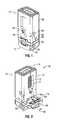
- FIG. 1is a perspective view of an expandable cage according to an embodiment of the present disclosure with an expansion member secured between the first and second supporting members;
- FIG. 2is a perspective view of the expandable cage of FIG. 1 with the expansion member partially removed from its secured position between the first and second supporting members;
- FIG. 3is perspective exploded view of the expandable cage of FIG. 1 ;
- FIG. 4is a right side view of the expandable cage of FIG. 1 , showing section line 9 - 9 ;
- FIG. 5is a perspective view of the expansion member of the expandable cage of FIG. 1 ;
- FIG. 6is a top view of the expandable cage of FIG. 1 ;
- FIG. 7is a front view of the expandable cage of FIG. 1 ;
- FIG. 8is a bottom view of the expandable cage of FIG. 1 ;
- FIG. 9is a cross-sectional view of the expandable cage of FIG. 1 , taken along section line 9 - 9 of FIG. 4 ;
- FIG. 10is a perspective view of an insertion tool holding the expandable cage of FIG. 1 without the expandable member;
- FIG. 11is a front view of the insertion tool of FIG. 10 holding the expandable cage of FIG. 1 without the expansion member;
- FIG. 12is a cross-sectional view of the insertion tool of FIG. 10 holding the expandable cage of FIG. 1 without the expansion member, taken along section line 12 - 12 of FIG. 11 ;
- FIG. 13is a top view of a distal portion of the insertion tool of FIG. 10 holding the expandable cage of FIG. 1 without the expansion member;
- FIG. 14is a cross-sectional view of the insertion tool of FIG. 10 holding the expandable cage of FIG. 1 without the expansion member, taken along section line 14 - 14 of FIG. 13 ;
- FIG. 15is a rear perspective view of an expandable cage according to an alternate embodiment of the present disclosure with an expansion member secured between the first and second supporting members;
- FIG. 16is a front view of the expandable cage of FIG. 15 ;
- FIG. 17is right side view of the expandable cage of FIG. 15 ;
- FIG. 18is a top view of the expandable cage of FIG. 15 ;
- FIG. 19is a bottom view of the expandable cage of FIG. 15 ;
- FIG. 20is a front perspective view of the expandable cage of FIG. 15 ;
- FIG. 21is a front perspective view of the expandable cage of FIG. 15 with the expansion member separated from the expandable cage;
- FIG. 22is a perspective exploded view of the expandable cage of FIG. 15 ;
- FIG. 23is a perspective view of the expansion member of the expandable cage of FIG. 15 ;
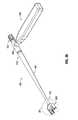
- FIG. 24is a perspective view of a driver according to an embodiment of the present disclosure.
- FIG. 25is an enlarged sectional view of a distal portion of the driver of FIG. 24 , taken around section 25 of FIG. 24 ;
- FIG. 26is a perspective exploded view of the driver of FIG. 24 ;
- FIG. 27is an enlarged sectional view of the distal portion of the driver of FIG. 24 , taken around section 27 of FIG. 26 ;
- FIG. 28is a top view of the driver of FIG. 24 ;
- FIG. 29is a cross-sectional view of the driver of FIG. 24 ; taken along section line 29 - 29 of FIG. 28 ;
- FIG. 30is an enlarged sectional view of a proximal portion of the driver of FIG. 24 ; taken around section 30 of FIG. 28 ;
- FIG. 31is an enlarged sectional view of the distal portion of the driver of FIG. 24 , taken around section 31 of FIG. 28 ;
- FIG. 32is a side view of the driver of FIG. 24 holding an expansion member of FIG. 23 ;
- FIG. 33is a top view of the driver of FIG. 24 holding the expansion member of FIG. 23 ;
- FIG. 34is an enlarged side view of the distal portion of the driver of FIG. 24 holding the expansion member of FIG. 23 , taken around section 34 of FIG. 32 ;
- FIG. 35is an enlarged top view of the distal portion of the driver of FIG. 24 holding the expansion member of FIG. 23 , taken around section 35 of FIG. 33 ;
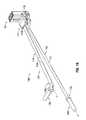
- FIG. 36is a perspective view of an insertion tool according to another embodiment of the present disclosure.
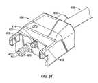
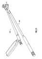
- FIG. 37is an enlarged perspective view of a distal portion of the insertion tool of FIG. 36 , taken around section 37 of FIG. 36 ;
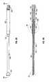
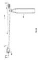
- FIG. 38is a side view of the insertion tool of FIG. 36 ;
- FIG. 39is a side cross-sectional view of the insertion tool of FIG. 35 , taken along section line 39 - 39 of FIG. 38 ;
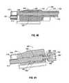
- FIG. 40is an enlarged side cross-sectional view of the distal portion of the insertion tool of FIG. 36 , taken around section 40 of FIG. 39 ;
- FIG. 41is a side cross-sectional view of the distal portion of the insertion tool of FIG. 36 , taken along section line 41 - 41 of FIG. 38 ;
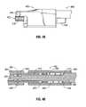
- FIG. 42is a front view of the insertion tool of FIG. 36 ;
- FIG. 43is an enlarged front view of the insertion tool of FIG. 36 , taken around section 43 of FIG. 42 ;
- FIG. 44is a side view of the insertion tool of FIG. 36 ;
- FIG. 45is an enlarged side view of the distal portion of the insertion tool of FIG. 44 , taken around section 45 of FIG. 44 ;
- FIG. 46is a side cross-sectional view of a proximal portion of the insertion tool of FIG. 36 , taken around section 46 of FIG. 39 ;
- FIG. 47is a perspective exploded view of the insertion tool of FIG. 36 ;
- FIG. 48is a perspective exploded view of the distal portion of the insertion tool of FIG. 36 ;
- FIG. 49is a rear view of the insertion tool of FIG. 36 holding the expandable cage of FIG. 15 ;
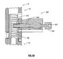
- FIG. 50is a side cross-sectional view of the distal portion of the insertion tool of FIG. 36 holding the expandable cage of FIG. 15 , taken around section 52 of FIG. 51 ;
- FIG. 51is a perspective view of the driver of FIG. 24 and the insertion tool of FIG. 36 holding the expandable cage of FIG. 15 ;
- FIG. 52is a top view of the distal portion of the insertion tool of FIG. 36 holding the expandable cage of FIG. 15 ;
- FIG. 53is a front cross-sectional view of the distal portion of the insertion tool of FIG. 36 holding the expandable cage of FIG. 15 , taken along section line 53 - 53 of FIG. 52 .
- proximalwill refer to the end of a tool or device that is closest to the operator
- distalwill refer to the end of the tool or device that is farthest from the operator.
- cephaladis used in this application to indicate a direction toward a patient's head
- the term “caudad”indicates a direction toward the patient's feet.
- a “bone support matrix”is a material that facilitates new bone growth between the opposing vertebral bodies. Suitable bone support matrices can be resorbable or nonresorbable and osteoconductive or osteoinductive. Examples of suitable bone support matrices include synthetic materials, bone morphogenic proteins (BMPs), and heterologous, homologous, or autologous bone and derivatives thereof. The bone support matrix may be radiolucent on x-rays.
- FIGS. 1 and 2show an expandable cage 10 designed for supporting adjacent vertebra and promoting spinal fusion.
- Expandable cage 10which may be made of autologous bone graft, bone allograft, polyetheretherketone (PEEK), titanium, stainless steel, cobalt chrome, polymeric materials, a combination thereof, or any other suitable material, includes first and second supporting members 12 , 14 configured to move relative to each other and an expansion member 16 removably positioned between first and second supporting members 12 , 14 .
- Expandable cage 10may be part of a kit including first and second supporting members 12 , 14 and several expansion members 16 of different sizes. The different expansion members 16 are dimensioned to maintain first and second supporting members 12 , 14 in different relative positions.
- the plurality of expansion members 16allows a user to adjust and fix expandable cage 10 at different heights.
- the usercan adjust the relative position of first and second supporting members 12 , 14 to accommodate expandable cage 10 in a variable space located between adjacent vertebrae. After placing expandable cage 10 in such space, the user positions the appropriate expansion member 16 between first and second supporting members 12 , 14 to maintain their relative position, thus fixing the expandable cage 10 at the desired height.
- first supporting member 12 of expandable cage 10includes a first supporting end 20 and an elongate body 18 extending from first supporting end 20 .
- elongate body 18may be a C-shaped structure. It is envisioned, however, that elongate body 18 may have any suitable structure, shape or configuration. Regardless of its shape, elongate body 18 defines a longitudinal passage 22 extending therethrough. Longitudinal passage 22 is adapted to receive optional autologous bone graft, bone allograft, bone slurry, bone chips, bone morphogenic protein or any other bone support matrix suitable for promoting bony union between vertebrae. In the embodiment depicted in FIG.
- first, second, and third walls 28 , 30 , 32collectively define longitudinal passage 22 and form elongate body 18 .
- Each of first, second and third walls 28 , 30 , 32have flat outer surfaces.
- Second wall 30interconnects first and third walls 28 , 32 .
- First wall 28is transversely secured to second wall 30
- second wall 30is transversely attached to third wall 32 .
- First and third walls 28 , 32are arranged in parallel with respect to each other.
- Second wall 30is arranged in a substantially orthogonal relationship with first and third walls 28 , 32 .
- First wall 28contains a slot 34 disposed along an outer surface thereof, as depicted in FIG. 9 .
- Slot 34is configured to slidably receive a pin 36 .
- Slot 34 and pin 36jointly allow first and second supporting members 12 , 14 to slide relative to each other while maintaining alignment of the parts, inhibiting relative rotational movement of the parts, and inhibiting separation of the parts.
- first wall 28includes a plurality of undulations or indentations 42 spreading along an inner surface thereof. Undulations 42 together form rack 66 configured to engage a head 122 of an insertion tool 100 . (See for example FIGS. 12 and 14 ).
- Third wall 32features a slot 38 formed along an outer surface thereof. Slot 38 is adapted to slidably receive a pin 40 . Slot 38 and pin 48 cooperatively allow first and second support members 12 , 14 to slide with respect to each other while maintaining alignment of the parts, inhibiting relative rotational movement of the parts, and inhibiting separation of the parts.
- first supporting end 20includes an engagement surface 24 and an abutting surface 26 disposed in directly opposite relation with respect to each other.
- Abutting surface 26faces second supporting member 14
- engagement surface 24faces away from second supporting member 14 , when second support member 14 is at least partially placed over first supporting member 12 .
- Engagement surface 24contains a plurality of teeth 44 adapted to engage a vertebra, or any other kind of tissue, and a recess 46 disposed around a central area thereof. Teeth 44 are arranged in longitudinal rows spreading along the width of engagement surface 24 . Each tooth 44 defines an oblique angle in relation to the abutting surface 26 , as seen in FIG. 4 . Nonetheless, engagement surface 24 may alternatively have teeth 44 having other configurations and arrangements or any other structure capable of engaging tissue.
- Recess 46has a substantially rectangular shape and is configured to receive any suitable bone support matrix to promote spinal fusion between adjacent vertebrae.
- first supporting member end 20further includes at least one hole 48 disposed in recess 46 .
- Hole 48extends through first supporting end 20 and provides access to longitudinal passage 22 ( FIG. 3 ).
- bone support matrixenters longitudinal passage 22 (see FIG. 3 ) through hole 48 .
- first supporting end 20includes six (6) holes 48 having circular cross-sections and arranged in longitudinal rows.
- First supporting end 20may have fewer or more holes 48 .
- holes 48may have any other suitable configuration or arrangement.
- first supporting end 20additionally includes cavities 50 , 52 disposed on opposite lateral sides 54 , 56 thereof.
- Each cavity 50 , 52( FIGS. 1 and 4 ) is adapted to receive arms 118 of an insertion tool 100 . (See FIGS. 10 and 13 ).
- a usermay advance expandable cage 10 toward the desired surgical site by positioning arms 118 of an insertion tool 100 (See FIG. 10 ) within cavities 50 , 52 of first supporting end 20 and advancing insertion tool 100 toward the surgical site.
- first supporting end 20includes an abutment surface 26 , as discussed above.
- Abutment surface 26interconnects first, second, and third walls 28 , 30 , 32 and abuts at least a portion of expansion member 16 when expansion member 16 is placed between first and second supporting members 12 , 14 .
- abutment surface 26includes a locking recess 58 adapted to securely receive a locking portion 60 of a backspan 59 of expansion member 16 .
- Locking portion 60defines an opening 73 for allowing access of bone support matrix into longitudinal passage 22 .
- expansion member 16includes a pair of legs 62 extending transversely with respect to backspan 59 which includes locking portion 60 .
- Locking portion 60is configured to securely engage locking recess 58 of first supporting member 12 and a locking recess 64 formed on second supporting member 14 .
- Locking portion 60 and locking recesses 58 , 64form a dovetail joint with a locking mechanism 68 .
- Locking mechanism 68may be, for example, a snap-fit coupling; however, locking mechanism 68 may include any other suitable coupling configured to connect expansion member 16 to first and second supporting members 12 , 14 .
- locking portion 60 of backspan 59includes first and second snap-fit arms 61 , 63 .
- First and second snap-fit arms 61 , 63are disposed on directly opposite surfaces of the backspan 59 relative to each other.
- Each of the first and second snap-fit arm 61 , 63are pivotally (or hingedly) connected to locking portion 60 at one end, i.e., cantilevered.
- First snap-fit arm 61is adapted to be releasably coupled to locking recess 58 of first supporting end 20
- second snap-fit arm 63is configured to be releasably connected to locking recess 64 of second supporting member 14 .
- second snap-fit arm 63includes a snap-fit detent 71 .
- the first snap-fit arm 61also includes a snap-fit detent (not shown).
- the snap-fit detent of snap-fit arm 61is substantially identical to snap-fit detent 71 of snap-fit arm 63 .
- Locking recesses 58 , 64each include an engagement wall 67 , 69 ( FIGS. 2 and 3 ). Each engagement wall 67 , 69 is configured to engage first and second snap-fit detents 63 , 71 to secure expansion member 16 to first and second supporting members 12 , 14 .
- first and second snap-fit arms 61 , 63pivots about the cantilevered end away from engagement walls 67 , 69 in order to disengage snap-fit detents 65 , 71 from engagement walls 67 , 69 .
- second supporting member 14includes an elongate body 70 defining a longitudinal passage 72 and a second supporting end 74 .
- Elongate body 70additionally includes a rectangular aperture 77 leading to longitudinal passage 72 .
- Longitudinal passage 72is dimensioned to slidably receive elongate body 18 of first supporting member 12 and is configured to receive bone support matrix.
- Second supporting end 74includes a plurality of teeth 76 ( FIG. 6 ) configured to engage tissue. As seen in FIG. 6 , teeth 76 are arranged in longitudinal rows spanning the width of second supporting end 74 . Each tooth 76 defines an oblique angle relative to the second supporting end 74 , as shown in FIG. 4 .
- Second supporting end 74further includes a recess 78 ( FIG. 6 ) disposed around a central area thereof. Recess 78 is adapted to receive bone support matrix therein. Additionally, second supporting end 74 includes at least one hole 80 ( FIG. 6 ) located in recess 78 . Hole 80 provides access to longitudinal passage 72 . In use, bone support matrix migrates from recess 78 to longitudinal passage 72 through hole 80 . In the depicted embodiment, second supporting end 74 contains six (6) holes 80 having circular cross-sections and arranged in longitudinal rows ( FIG. 6 ). Second supporting end 74 , however, may include more or fewer holes 80 having different configurations and arrangements.
- second supporting member 14additionally includes cavities 82 , 84 positioned on opposite lateral sides 86 , 88 . Each cavity 82 , 84 is adapted to receive arms 118 of insertion tool 100 . (See FIG. 10 ). Second supporting member 14 also has holes 90 , 92 on each lateral side 86 , 88 . Hole 90 , which is located on lateral side 86 , provides pin 40 access to slot 38 , whereas hole 92 , which is positioned on lateral side 88 , provides pin 36 access to slot 34 . (See FIG. 9 ). Moreover, second supporting member 14 contains an opening 94 ( FIG. 7 ) leading to longitudinal passage 72 and another opening 96 ( FIG.
- Opening 94includes an inner thread 95 ( FIG. 1 ) and is adapted to receive pin 120 of insertion tool 100 (see FIG. 14 ). Further, opening 96 is configured to receive head 122 of insertion tool 100 (see FIG. 12 ) and threaded tip 414 of insertion tool 400 ( FIG. 37 ). Openings 94 , 96 are positioned on a front surface of second support member 14 , as seen in FIG. 7 .
- Insertion portion 102includes an elongate member 110 defining a longitudinal axis “A” and a handle 106 .
- Elongate member 110has a tapered section 110 t .
- Handle 106extends transversely from a proximal portion 110 p of elongate member 110 .
- Driver 104includes an elongate member 112 defining a longitudinal axis “B” and a handle 108 .
- Handle 108extends from a proximal portion 112 p of elongate body 112 .
- Longitudinal axis “B”defines an oblique angle relative to longitudinal axis “A.”
- a holding portion 114interconnects insertion portion 102 and driver 104 . Specifically, a distal end 110 d of elongate member 110 is fixedly attached to holding portion 114 , and a distal end 112 d of elongate member 112 is rotatably connected to holding portion 114 .
- Holding portion 114includes a bore 116 for receiving distal end 112 d of elongate member 112 and a pair of arms 118 adapted to be received within cavities 50 , 52 of first supporting member 12 or cavities 82 , 84 of second supporting member 14 . (See FIGS. 1-4 ).
- Distal end 112 d of elongate member 112has a head 122 with a plurality of teeth 124 ( FIG. 14 ).
- Head 122is configured to be received within opening 96 of second supporting member 14 .
- Teeth 124are configured to engage rack 66 . In operation, the rotation of head 122 causes the linear motion of rack 66 .
- Holding portion 114further includes a pin 120 protruding distally therefrom. Pin 120 is adapted to be received within opening 94 of second supporting member 14 .
- a useremploys insertion tool 100 to position expandable cage 10 between adjacent vertebrae and to move first and second supporting members 12 , 14 relative to each other to expand expandable cage 10 .
- the userholds expandable cage 10 with insertion tool 100 by placing arms 118 within cavities 82 , 84 , pin 120 through opening 94 of second supporting member 14 , and head 122 through opening 96 of second supporting member 14 .
- the useradvances insertion tool 100 toward the desired surgical site and places expandable cage 10 in the prepared space between vertebrae.
- the usermoves either first or second support member 12 or 14 relative to the other to adjust the height of expandable cage 10 .
- first and second support members 12 , 14To slide first and second support members 12 , 14 with respect to each other, the user rotates driver 106 . As driver 106 rotates, teeth 124 of head 122 engage rack 66 and cause first and second support members 12 , 14 to move apart longitudinally with respect to the other. Once the desired relative position of first and second supporting members 12 , 14 has been attained, the user places expansion member 16 between first and second supporting members 12 , 14 to fix their relative position. The user is provided with expansion members 16 of different sizes. The user utilizes the expansion member 16 most suitable to achieve the desired expandable cage 10 height. As expandable member 16 is inserted between first and second support members 12 , 14 , locking portion 60 engages locking recesses 58 , 64 and secures expansion member 16 to first and second supporting member 12 , 14 .
- Recesses 46 , 78may be packed with bone support matrix prior to insertion of expandable cage 10
- longitudinal recess 22may be packed with bone support matrix material after expandable cage 10 has been positioned. Bone support matrix material may be added to expandable cage 10 through aperture 77 .
- FIGS. 15-20show another embodiment of the presently disclosed expandable cage 200 .
- the construction and operation of expandable cage 200is substantially similar to the construction and operation of expandable cage 10 .
- the present disclosurediscusses the differences between expandable cage 200 and 10 .
- Identical or similar reference charactersdesignate similar or identical elements in expandable cage 10 and expandable cage 200 .
- expandable cage 200includes an expansion member 16 substantially similar to expansion member 16 of expandable cage 10 .
- expansion member 16 of expandable cage 200includes a threaded bore 273 (FIG. 20 ) in lieu of opening 73 ( FIG. 3 ) of expansion member 16 of expandable cage 10 .
- Threaded bore 273extends through locking portion 60 of expansion member 16 and includes an inner thread 275 ( FIG. 20 ) adapted to mate with a threaded tip 314 of insertion tool 300 ( FIG. 24 ).
- Elongate body 70 of second supporting member 14has a rectangular aperture 277 substantially similar to rectangular aperture 77 ( FIG. 2 ). The cross-sectional area of rectangular aperture 277 is smaller than the cross-sectional area of rectangular aperture 77 ( FIG. 2 ).
- second supporting end 74 of second supporting member 14includes an elliptical opening 278 instead of recess 78 ( FIG. 6 ) of expandable cage 10 .
- Elliptical opening 278is disposed around a central area of second supporting end 74 and is adapted to allow access of bone support matrix into longitudinal passage 22 .
- first supporting end 20 of first supporting member 12includes an elliptical opening 246 instead of recess 46 ( FIG. 8 ) of expandable cage 10 .
- Elliptical opening 246has a smaller cross-section than elliptical opening 278 of second supporting end 74 ( FIG. 18 ).
- elliptical opening 246is disposed around a central area of first supporting end 20 and is adapted to allow access of bone support matrix into longitudinal passage 22 .
- first, second and third walls 28 , 30 , 32 of elongate body 18have rounded outer surfaces as opposed to flat outer surfaces.
- First, second, and third walls 28 , 30 , 32still collectively define longitudinal passage 22 .
- expansion member 16includes a locking portion 60 and pair of legs 62 extending transversely from locking portion 60 .
- Each leg 62includes a round inner surface 279 configured to mate with the rounded outer surfaces of walls 28 , 32 .
- Expansion member 16 of expandable cage 200further includes a threaded hole 276 disposed through locking portion 60 and an inner thread 275 formed around threaded hole 276 .
- Inner thread 275is adapted to mate with an external thread 315 ( FIG. 27 ) of threaded tip 314 of a driver 300 .
- FIGS. 24 and 25illustrate another embodiment of a driver 300 for adjusting the relative position of first and second supporting members 12 , 14 .
- Driver 300which is configured to be used in conjunction with insertion tool 400 ( FIG. 36 ) or any other suitable insertion tool, includes a handle 302 , a holding portion 304 , and an elongate portion 306 interconnecting handle 302 and holding portion 304 .
- Elongate portion 306extends distally from handle 302 and defines a longitudinal axis “C.”
- Holding portion 304includes first and second arms 308 , 310 extending distally therefrom, as seen in FIG. 25 .
- First and second arms 308 , 310define a gap therebetween.
- holding portion 304includes a distal opening 312 for exposing a threaded tip 314 of driver 300 .
- Distal opening 312is disposed in communication with a bore 316 extending through elongate portion 306 .
- Bore 316is configured to accommodate a tubular member 318 .
- driver 300further includes tubular member 318 having a longitudinal opening 320 .
- Longitudinal opening 320extends through tubular member 318 and is dimensioned to receive a rod 322 .
- Rod 322includes a threaded tip 314 located at a distal end 324 thereof.
- Threaded tip 314includes an external thread 315 adapted to mate with inner thread 275 of threaded hole 273 of expansion member 16 ( FIG. 20 ).
- a proximal end 326 of rod 322is attached to a knob 328 .
- Knob 328allows a user to rotate rod 322 .
- handle 306defines a bore 330 dimensioned to receive a proximal section 332 of elongate portion 306 .
- Proximal section 332 of elongate portion 306has a diameter that is larger than the diameter of the rest of elongate portion 306 .
- proximal section 332 of elongate portion 306includes first and second flat surfaces 334 , 336 .
- First and second flat surfaces 334 , 336are disposed in a diametrically opposed relation relative to each other and are collectively configured to retain a distal portion 340 of a biasing member 338 .
- biasing member 338is a coil spring, but biasing member 338 may be any suitable mechanism, apparatus, means, or device.
- a proximal portion 342 of biasing member 338abuts an annular internal surface 344 of handle 306 .
- Biasing member 338biases rod 322 in a distal direction.
- a plurality of pins 346or any other suitable apparatus, secures handle 306 to tubular member 318 and elongate portion 306 .
- rod 322is slidably positioned in longitudinal opening 320 of tubular member 318 .
- Tubular member 318is slidably disposed in bore 316 of elongate portion 306 .
- biasing member 338biases rod 322 distally so that at least a portion of threaded tip 314 is located outside of bore 316 .
- driver 300can be employed, among other things, for holding and inserting expansion member 16 of expandable cage 200 between first ands second supporting members 12 , 14 .
- expansion member 16 of expandable cage 200includes a threaded bore 273 having inner thread 275 ( FIG. 20 ), and driver 300 includes a threaded tip 314 having an external thread 315 .
- Inner thread 275is adapted to mate with external thread 315 of threaded tip 314 .
- a userinserts at least a portion of threaded tip 314 of driver 300 in threaded hole 237 of expansion member 16 .
- first and second arms 308 , 310abut an upper surface of expansion member 16 , as seen in FIG.
- driver 300can also be used in conjunction with insertion tool 400 ( FIG. 36 ) which displaces first and second supporting members 12 , 14 relative to each other in preparation to receive expansion member 16 .
- FIGS. 36 and 37show an insertion tool 400 designed for inserting expandable cage 10 inside into a prepared space in the body.
- Insertion tool 400generally includes a handle 402 , an elongate section 404 oriented transversely relative to handle 402 , and a holding section 406 attached to a distal portion 408 of elongate section 404 .
- Handle 402facilitates gripping by a user and is operably coupled to a proximal portion 410 of elongate section 404 .
- holding section 406is adapted to hold expandable cage 10 and includes a hexalobular head 412 rotatably mounted thereon, a threaded tip 414 also rotatably mounted thereon, and first and second arms 416 , 418 extending distally therefrom.
- Hexalobular head 412includes teeth 420 each configured to engage undulations 42 of rack 66 of first support member 12 ( FIGS. 3 and 9 ). As discussed in detail below, rotating hexalobular head 412 when teeth 420 are engaged with undulations 42 of rack 66 causes first and second supporting members 12 , 14 to move relative to each other.
- Threaded tip 414is dimensioned to be received within opening 94 and includes an external thread 422 formed thereabout. External thread 422 of threaded tip 414 is adapted to mate inner thread 95 of opening 94 of first support member 12 ( FIG. 1 ) to secure holding section 406 of insertion tool 400 to expandable cage 10 ( FIG. 1 ).
- First and second arms 416 , 418define a gap therebetween. Each of first and second arms 416 , 418 is configured to be received in cavities 82 , 84 of expandable cage 10 ( FIGS. 1 and 4 ). When first and second arms 416 , 418 are positioned in cavities 82 , 84 of expandable cage 10 ( FIGS. 1 and 4 ), holding section 406 retains expandable cage 10 .
- insertion tool 400includes a rod 424 slidably disposed through elongate section 404 .
- Elongate section 404has a longitudinal opening 426 extending therethrough. Longitudinal opening 426 of elongate section 404 is dimensioned to slidably receive rod 424 .
- Rod 424has a proximal portion 428 and a distal portion 430 .
- a knob 432is attached to proximal portion 428 of rod 424 .
- Distal portion 430 of rod 424is connected to threaded tip 414 .
- elongate section 404includes a thread 434 disposed around distal portion 408 .
- Thread 434is adapted to mate with an inner thread 436 of holding section 406 .
- thread 434 of elongate section 404mates with inner thread 436 of holding section 406
- elongate section 404attaches to holding section 406 .
- holding section 406includes a first bore 438 dimensioned to receive distal portion 430 of rod 424 , at least part of distal portion 408 of elongate section 404 , and threaded tip 414 .
- Holding section 406further includes a thread 440 formed around a portion of first bore 438 .
- Thread 440is adapted to mate with thread 434 of rod 424 to fix the position of rod 424 relative to holding section 406 .
- holding section 406includes a second bore 442 oriented at an oblique angle relative to first bore 438 ( FIGS. 38 and 40 ).
- Second bore 442is dimensioned to slidably receive a bar 444 .
- Bar 444has a proximal portion 446 and a distal portion 448 .
- Distal portion 448 of bar 444is attached to hexalobular head 412
- proximal portion 446 of bar 444is connected to a cylindrical member 450 .
- Cylindrical member 450includes a socket 452 configured to receive and engage threaded tip 314 of driver 300 as described in greater detail below with reference to FIGS. 49-53 .
- Bar 444is rotatably disposed in bore 442 such that, when threaded tip 314 of driver 300 engages socket 452 , rotating threaded tip 314 causes the rotation of bar 444 .
- Holding section 406further includes a biasing member 454 , such as a spring, partially positioned inside bore 442 .
- Biasing member 454includes a proximal end 456 attached to cylindrical member 450 and a distal end 458 abutting an inner annular wall 460 of holding section 406 . In operation, biasing member 454 biases bar 444 proximally.
- insertion tool 400further includes a coupling member 460 for connecting handle 402 to elongate section 404 .
- Coupling member 460includes a tubular portion 462 and shaft 464 extending transversely from tubular portion 462 .
- tubular portion 462defines a longitudinal opening 466 extending therethrough. Longitudinal opening 466 is configured to receive at least part of proximal portion 410 of elongate section 404 and at least part of proximal portion 428 of rod 424 .
- a biasing member 468such as a spring, partially surrounds proximal portion 428 of rod 424 and has a proximal end 470 and a distal end 472 .
- Proximal end 470 of biasing member 468abuts an annular wall 474 located on proximal portion 428 of rod 424 .
- Distal end 472 of biasing member 468is attached to proximal portion 410 of elongate section 404 .
- Biasing member 468is disposed in longitudinal opening 466 of tubular portion 462 , and in operation, biases rod 424 in a proximal direction.
- shaft 464 of coupling member 460is positioned inside handle 402 .
- a pin 476or any other suitable device, apparatus, or means, couples handle 406 to shaft 464 , thereby connecting handle 402 to coupling member 460 .
- Shaft 464includes a hole 478 adapted to receive pin 476 .
- Handle 402also includes a hole 480 adapted to receive pin 476 .
- insertion tool 400additionally includes a plurality of pins 482 for connecting rod 424 to elongate section 404 .
- Rod 424includes a depressed area 484 having a smaller diameter than the surrounding portions of rod 424 .
- pins 482seat on diametrically opposed sides of depressed area 484 to secure rod 424 to elongate section 404 . (See FIG. 46 ).
- bar 444 of holding section 406includes a plurality of teeth 486 protruding proximally from proximal portion 446 .
- Teeth 486are disposed annularly on a proximal surface 492 ( FIG. 41 ) of bar 444 and are oriented at an oblique angle with respect to bar 444 .
- Holding section 406defines a recess 488 dimensioned to fixedly receive a tab 490 .
- Tab 490includes a plurality of teeth 494 adapted to engage teeth 486 of bar 444 .
- Teeth 494 of tab 490are disposed annularly on a bottom portion of a distal surface 946 of tab 490 and are oriented at an oblique angle with respect to tab 490 .
- the orientations of teeth 486 and 494allow bar 444 to rotate in one direction, while inhibiting or precluding rotation of bar 444 in the opposite direction.
- a usercan employ driver 300 and insertion tool 400 to place and expand expandable cage 10 in the desired surgical site.
- the userpositions holding portion 406 of insertion tool 400 on expandable cage 10 so that first and second arms 416 , 418 ( FIG. 37 ) are disposed in cavities 82 , 84 ( FIGS. 4 and 5 ). While first and second arms 416 , 418 are placed in cavities 82 , 84 , hexalobular head 412 of insertion tool 400 passes through opening 96 ( FIG. 7 ) of expandable cage 10 to reach rack 66 , and threaded tip 414 of insertion tool 400 ( FIG. 37 ) passes through opening 94 ( FIG. 7 ) of expandable cage 10 .
- the userAfter securing insertion tool 400 to expandable cage 10 , the user advances insertion tool 400 toward the desired surgical site to position expandable cage 10 in a space between vertebrae. Once expandable cage 10 has been positioned between the vertebrae, the user moves first and second supporting members 12 , 14 relative to each other to adjust the height of expandable cage 10 . In order to displace first and second supporting members 12 , 14 relative to each other, the user first positions threaded tip 314 of driver 300 ( FIGS. 24 and 25 ) into socket 452 of insertion tool 400 . Next, the user rotates rod 322 of driver 300 through knob 228 to urge the rotation of hexalobular head 412 .
- first and second supporting members 12 , 14move apart relative to each other to adjust the height of expandable cage 10 .
- the useradjusts the height of expandable cage 10 until a first supporting end 20 and second supporting end 74 engage the vertebral bodies of adjacent vertebrae.
- the userdetaches driver 300 from insertion tool 400 and holds expansion member 16 with driver 300 as discussed in detail above (See FIGS. 32-35 ).
- the useradvances driver 300 toward expandable cage 10 to position expansion member 16 between first and second supporting members 12 , 14 .
- locking portion 60 of expansion member 16engages locking recesses 58 , 64 ( FIG. 3 ) to fix expansion member 16 to expandable cage 10 .
- expansion member 16maintains the relative position of first and second supporting members 12 , 14 of expandable cage 10 .
- the userpacks the space between adjacent vertebrae with bone support matrix.
Landscapes
- Health & Medical Sciences (AREA)
- Engineering & Computer Science (AREA)
- Biomedical Technology (AREA)
- Orthopedic Medicine & Surgery (AREA)
- Neurology (AREA)
- Transplantation (AREA)
- Heart & Thoracic Surgery (AREA)
- Oral & Maxillofacial Surgery (AREA)
- Cardiology (AREA)
- Vascular Medicine (AREA)
- Life Sciences & Earth Sciences (AREA)
- Animal Behavior & Ethology (AREA)
- General Health & Medical Sciences (AREA)
- Public Health (AREA)
- Veterinary Medicine (AREA)
- Physical Education & Sports Medicine (AREA)
- Surgical Instruments (AREA)
- Prostheses (AREA)
Abstract
Description
Claims (21)
Priority Applications (2)
| Application Number | Priority Date | Filing Date | Title |
|---|---|---|---|
| US12/602,868US8673011B2 (en) | 2008-03-28 | 2009-03-30 | Expandable cage |
| US14/192,027US9539107B2 (en) | 2008-03-28 | 2014-02-27 | Expandable cage |
Applications Claiming Priority (4)
| Application Number | Priority Date | Filing Date | Title |
|---|---|---|---|
| US7217608P | 2008-03-28 | 2008-03-28 | |
| US8704608P | 2008-08-07 | 2008-08-07 | |
| US12/602,868US8673011B2 (en) | 2008-03-28 | 2009-03-30 | Expandable cage |
| PCT/US2009/038780WO2009151734A1 (en) | 2008-03-28 | 2009-03-30 | Expandable cage |
Related Child Applications (1)
| Application Number | Title | Priority Date | Filing Date |
|---|---|---|---|
| US14/192,027ContinuationUS9539107B2 (en) | 2008-03-28 | 2014-02-27 | Expandable cage |
Publications (2)
| Publication Number | Publication Date |
|---|---|
| US20100179594A1 US20100179594A1 (en) | 2010-07-15 |
| US8673011B2true US8673011B2 (en) | 2014-03-18 |
Family
ID=42664327
Family Applications (2)
| Application Number | Title | Priority Date | Filing Date |
|---|---|---|---|
| US12/602,868Active2032-03-18US8673011B2 (en) | 2008-03-28 | 2009-03-30 | Expandable cage |
| US14/192,027ActiveUS9539107B2 (en) | 2008-03-28 | 2014-02-27 | Expandable cage |
Family Applications After (1)
| Application Number | Title | Priority Date | Filing Date |
|---|---|---|---|
| US14/192,027ActiveUS9539107B2 (en) | 2008-03-28 | 2014-02-27 | Expandable cage |
Country Status (4)
| Country | Link |
|---|---|
| US (2) | US8673011B2 (en) |
| EP (1) | EP2268219B1 (en) |
| AU (1) | AU2009257987B2 (en) |
| WO (1) | WO2009151734A1 (en) |
Cited By (21)
| Publication number | Priority date | Publication date | Assignee | Title |
|---|---|---|---|---|
| US20140114134A1 (en)* | 2012-10-20 | 2014-04-24 | K2M, Inc. | Lateral distractor |
| US20140277509A1 (en)* | 2013-03-15 | 2014-09-18 | Spectrum Spine Ip Holdings, Llc | Expandable vertebral body replacement and methods |
| US8920502B1 (en)* | 2006-11-08 | 2014-12-30 | Spinal Usa, Inc. | Vertebral body replacement |
| US9216096B2 (en) | 2010-03-16 | 2015-12-22 | Pinnacle Spine Group, Llc | Intervertebral implants and related tools |
| US9380932B1 (en) | 2011-11-02 | 2016-07-05 | Pinnacle Spine Group, Llc | Retractor devices for minimally invasive access to the spine |
| EP3050540A1 (en) | 2015-01-27 | 2016-08-03 | K2M, Inc. | Spinal implant |
| US9456907B1 (en)* | 2005-03-24 | 2016-10-04 | Igip, Llc | Extendable spinal implant |
| WO2017066443A1 (en) | 2015-10-13 | 2017-04-20 | K2M, Inc. | Interbody spacer |
| US9707096B2 (en) | 2013-03-14 | 2017-07-18 | K2M, Inc. | Spinal fixation device |
| US10028841B2 (en) | 2015-01-27 | 2018-07-24 | K2M, Inc. | Interbody spacer |
| US10070970B2 (en) | 2013-03-14 | 2018-09-11 | Pinnacle Spine Group, Llc | Interbody implants and graft delivery systems |
| US20190060081A1 (en)* | 2013-05-14 | 2019-02-28 | Expanding Innovations, Inc. | Intervertebral devices and related methods |
| US10292832B2 (en) | 2013-03-14 | 2019-05-21 | Ohio State Innovation Foundation | Spinal fixation device |
| US10327908B2 (en) | 2015-09-18 | 2019-06-25 | K2M, Inc. | Corpectomy device and methods of use thereof |
| WO2019165445A1 (en) | 2018-02-26 | 2019-08-29 | K2M, Inc. | Spinal implants with custom density and 3-d printing of spinal implants |
| US10959855B2 (en) | 2017-05-25 | 2021-03-30 | Stryker European Holdings I, Llc | Fusion cage with integrated fixation and insertion features |
| US11006981B2 (en) | 2017-07-07 | 2021-05-18 | K2M, Inc. | Surgical implant and methods of additive manufacturing |
| US11020241B2 (en)* | 2016-02-23 | 2021-06-01 | Life Spine, Inc. | Expandable lateral spine cage with reverse dovetail configuration |
| AU2020289764B2 (en)* | 2017-07-28 | 2021-12-16 | Wright Medical Technology, Inc. | Joint osteotomy system and method |
| US12279965B2 (en) | 2017-09-08 | 2025-04-22 | Xtant Medical Holdings, Inc. | Intervertebral implants, instruments, and methods |
| US12409045B2 (en) | 2019-09-16 | 2025-09-09 | Vb Spine Us Opco Llc | 3D printed cervical standalone implant |
Families Citing this family (54)
| Publication number | Priority date | Publication date | Assignee | Title |
|---|---|---|---|---|
| US6793678B2 (en) | 2002-06-27 | 2004-09-21 | Depuy Acromed, Inc. | Prosthetic intervertebral motion disc having dampening |
| AU2004212942A1 (en) | 2003-02-14 | 2004-09-02 | Depuy Spine, Inc. | In-situ formed intervertebral fusion device |
| US20040267367A1 (en) | 2003-06-30 | 2004-12-30 | Depuy Acromed, Inc | Intervertebral implant with conformable endplate |
| US8636802B2 (en) | 2004-03-06 | 2014-01-28 | DePuy Synthes Products, LLC | Dynamized interspinal implant |
| WO2008070863A2 (en) | 2006-12-07 | 2008-06-12 | Interventional Spine, Inc. | Intervertebral implant |
| US8900307B2 (en) | 2007-06-26 | 2014-12-02 | DePuy Synthes Products, LLC | Highly lordosed fusion cage |
| EP2237748B1 (en) | 2008-01-17 | 2012-09-05 | Synthes GmbH | An expandable intervertebral implant |
| US8936641B2 (en) | 2008-04-05 | 2015-01-20 | DePuy Synthes Products, LLC | Expandable intervertebral implant |
| EP2323574B1 (en)* | 2008-08-13 | 2012-02-15 | Synthes GmbH | Interspinous spacer assembly |
| US9526620B2 (en) | 2009-03-30 | 2016-12-27 | DePuy Synthes Products, Inc. | Zero profile spinal fusion cage |
| KR101687435B1 (en) | 2009-07-06 | 2016-12-19 | 신세스 게엠바하 | Expandable fixation assemblies |
| US9393129B2 (en) | 2009-12-10 | 2016-07-19 | DePuy Synthes Products, Inc. | Bellows-like expandable interbody fusion cage |
| DE102010018379B4 (en)* | 2010-04-26 | 2018-10-18 | Peter Metz-Stavenhagen | Spine implant and tool for this |
| US9402744B2 (en) | 2010-06-11 | 2016-08-02 | International Spinal Innovations, Llc | Pre-packed corpectomy device to improve fusion |
| US9907560B2 (en) | 2010-06-24 | 2018-03-06 | DePuy Synthes Products, Inc. | Flexible vertebral body shavers |
| US8979860B2 (en) | 2010-06-24 | 2015-03-17 | DePuy Synthes Products. LLC | Enhanced cage insertion device |
| US8623091B2 (en) | 2010-06-29 | 2014-01-07 | DePuy Synthes Products, LLC | Distractible intervertebral implant |
| US20120078372A1 (en) | 2010-09-23 | 2012-03-29 | Thomas Gamache | Novel implant inserter having a laterally-extending dovetail engagement feature |
| US9402732B2 (en) | 2010-10-11 | 2016-08-02 | DePuy Synthes Products, Inc. | Expandable interspinous process spacer implant |
| DE102010047901B4 (en)* | 2010-10-11 | 2019-01-10 | Heinrich Böhm | Implant for the spine and operating instrument |
| US9283086B2 (en) | 2011-03-03 | 2016-03-15 | Life Spine, Inc. | Expandable corpectomy cage |
| DE102011018695B4 (en) | 2011-04-26 | 2022-08-25 | Peter Metz-Stavenhagen | Spinal implant and tool therefor |
| DE102011018692B4 (en) | 2011-04-26 | 2016-06-23 | Peter Metz-Stavenhagen | Spinal implant, tool and method of distraction of the spinal implant |
| DE102011018694B4 (en) | 2011-04-26 | 2022-08-25 | Peter Metz-Stavenhagen | Spinal implant and tool therefor |
| US9248028B2 (en) | 2011-09-16 | 2016-02-02 | DePuy Synthes Products, Inc. | Removable, bone-securing cover plate for intervertebral fusion cage |
| US8795167B2 (en) | 2011-11-15 | 2014-08-05 | Baxano Surgical, Inc. | Spinal therapy lateral approach access instruments |
| US9622876B1 (en) | 2012-04-25 | 2017-04-18 | Theken Spine, Llc | Expandable support device and method of use |
| EP2877127B1 (en) | 2012-07-26 | 2019-08-21 | Synthes GmbH | Expandable implant |
| US9144503B2 (en)* | 2012-10-12 | 2015-09-29 | Warsaw Orthopedic, Inc. | Expandable spinal implant system and method |
| US8915947B2 (en) | 2012-10-18 | 2014-12-23 | Spectrum Spine Ip Holdings, Llc | Surgical access system |
| US9572684B2 (en)* | 2012-12-26 | 2017-02-21 | Innovasis, Inc. | Interbody insertion tool and method |
| US9717601B2 (en) | 2013-02-28 | 2017-08-01 | DePuy Synthes Products, Inc. | Expandable intervertebral implant, system, kit and method |
| US9522070B2 (en) | 2013-03-07 | 2016-12-20 | Interventional Spine, Inc. | Intervertebral implant |
| US8900312B2 (en) | 2013-03-12 | 2014-12-02 | Spine Wave, Inc. | Expandable interbody fusion device with graft chambers |
| WO2014145982A1 (en) | 2013-03-15 | 2014-09-18 | Spectrum Spine Ip Holdings, Llc | Expandable vertebral body replacement device, system, and methods |
| US9439783B2 (en)* | 2014-03-06 | 2016-09-13 | Spine Wave, Inc. | Inserter for expanding body tissue |
| US11426290B2 (en) | 2015-03-06 | 2022-08-30 | DePuy Synthes Products, Inc. | Expandable intervertebral implant, system, kit and method |
| DE102015110202B3 (en)* | 2015-06-25 | 2016-06-09 | Heraeus Medical Gmbh | Kit for constructing a cage for spinal fusion and method therefor and corresponding cage and its use |
| US9913727B2 (en) | 2015-07-02 | 2018-03-13 | Medos International Sarl | Expandable implant |
| EP3474784A2 (en) | 2016-06-28 | 2019-05-01 | Eit Emerging Implant Technologies GmbH | Expandable and angularly adjustable intervertebral cages with articulating joint |
| US11510788B2 (en) | 2016-06-28 | 2022-11-29 | Eit Emerging Implant Technologies Gmbh | Expandable, angularly adjustable intervertebral cages |
| US10537436B2 (en) | 2016-11-01 | 2020-01-21 | DePuy Synthes Products, Inc. | Curved expandable cage |
| US10888433B2 (en) | 2016-12-14 | 2021-01-12 | DePuy Synthes Products, Inc. | Intervertebral implant inserter and related methods |
| US10398563B2 (en) | 2017-05-08 | 2019-09-03 | Medos International Sarl | Expandable cage |
| US11344424B2 (en) | 2017-06-14 | 2022-05-31 | Medos International Sarl | Expandable intervertebral implant and related methods |
| US10940016B2 (en) | 2017-07-05 | 2021-03-09 | Medos International Sarl | Expandable intervertebral fusion cage |
| US11135070B2 (en)* | 2018-02-14 | 2021-10-05 | Titan Spine, Inc. | Modular adjustable corpectomy cage |
| US10993816B2 (en)* | 2018-05-18 | 2021-05-04 | Brian Kieser | In vivo rotatable PLIF additively manufactured and reading system therefor |
| US11446156B2 (en) | 2018-10-25 | 2022-09-20 | Medos International Sarl | Expandable intervertebral implant, inserter instrument, and related methods |
| US11426286B2 (en) | 2020-03-06 | 2022-08-30 | Eit Emerging Implant Technologies Gmbh | Expandable intervertebral implant |
| CN111870332B (en)* | 2020-06-10 | 2022-11-04 | 江苏省人民医院(南京医科大学第一附属医院) | Vertebral body bone expander |
| US11850160B2 (en) | 2021-03-26 | 2023-12-26 | Medos International Sarl | Expandable lordotic intervertebral fusion cage |
| US11752009B2 (en) | 2021-04-06 | 2023-09-12 | Medos International Sarl | Expandable intervertebral fusion cage |
| US12090064B2 (en) | 2022-03-01 | 2024-09-17 | Medos International Sarl | Stabilization members for expandable intervertebral implants, and related systems and methods |
Citations (55)
| Publication number | Priority date | Publication date | Assignee | Title |
|---|---|---|---|---|
| US4554914A (en) | 1983-10-04 | 1985-11-26 | Kapp John P | Prosthetic vertebral body |
| SU1560184A1 (en) | 1988-07-29 | 1990-04-30 | Харьковский Научно-Исследовательский Институт Ортопедии И Травматологии Им.Проф.М.И.Ситенко | Endoprosthesis of spinal column segments |
| US5236460A (en) | 1990-02-12 | 1993-08-17 | Midas Rex Pneumatic Tools, Inc. | Vertebral body prosthesis |
| US5290312A (en) | 1991-09-03 | 1994-03-01 | Alphatec | Artificial vertebral body |
| US5336223A (en) | 1993-02-04 | 1994-08-09 | Rogers Charles L | Telescoping spinal fixator |
| US5360430A (en) | 1993-07-29 | 1994-11-01 | Lin Chih I | Intervertebral locking device |
| US5458641A (en) | 1993-09-08 | 1995-10-17 | Ramirez Jimenez; Juan J. | Vertebral body prosthesis |
| US5571190A (en) | 1993-08-20 | 1996-11-05 | Heinrich Ulrich | Implant for the replacement of vertebrae and/or stabilization and fixing of the spinal column |
| US5571192A (en) | 1994-07-02 | 1996-11-05 | Heinrich Ulrich | Prosthetic vertebral implant |
| US5702455A (en) | 1996-07-03 | 1997-12-30 | Saggar; Rahul | Expandable prosthesis for spinal fusion |
| US5723013A (en) | 1995-02-06 | 1998-03-03 | Jbs S.A. | Spacer implant for substituting missing vertebrae |
| US5776198A (en) | 1994-12-09 | 1998-07-07 | Sdgi Holdings, Inc. | Adjustable vertebral body replacement |
| US5980522A (en) | 1994-07-22 | 1999-11-09 | Koros; Tibor | Expandable spinal implants |
| US5989290A (en) | 1995-05-24 | 1999-11-23 | Biedermann; Lutz | Height-adjustable artificial vertebral body |
| US6176881B1 (en) | 1997-04-15 | 2001-01-23 | Synthes | Telescopic vertebral prosthesis |
| US6183517B1 (en) | 1998-12-16 | 2001-02-06 | Loubert Suddaby | Expandable intervertebral fusion implant and applicator |
| US6193756B1 (en) | 1997-09-30 | 2001-02-27 | Sulzer Orthopaedie Ag | Tubular support body for bridging two vertebrae |
| US6193755B1 (en) | 1996-09-26 | 2001-02-27 | Howmedica Gmbh | Spinal cage assembly |
| US6200348B1 (en) | 1998-02-06 | 2001-03-13 | Biedermann, Motech Gmbh | Spacer with adjustable axial length |
| US6241769B1 (en) | 1998-05-06 | 2001-06-05 | Cortek, Inc. | Implant for spinal fusion |
| US6296665B1 (en) | 2000-03-20 | 2001-10-02 | Electro-Biology, Inc. | Method and apparatus for spinal fixation |
| US6332895B1 (en) | 2000-03-08 | 2001-12-25 | Loubert Suddaby | Expandable intervertebral fusion implant having improved stability |
| US6375683B1 (en) | 1997-05-02 | 2002-04-23 | Stryker France S.A. | Implant in particular for replacing a vertebral body in surgery of the spine |
| US6395034B1 (en) | 1999-11-24 | 2002-05-28 | Loubert Suddaby | Intervertebral disc prosthesis |
| US6419705B1 (en) | 1999-06-23 | 2002-07-16 | Sulzer Spine-Tech Inc. | Expandable fusion device and method |
| US6500178B2 (en) | 1997-01-02 | 2002-12-31 | St. Francis Medical Technologies, Inc. | Spine distraction implant and method |
| US6524341B2 (en) | 1998-10-15 | 2003-02-25 | Synthes (Usa) | Telescopic vertebral prosthesis |
| US6562074B2 (en) | 2001-10-17 | 2003-05-13 | Medicinelodge, Inc. | Adjustable bone fusion implant and method |
| US6610090B1 (en) | 1998-01-30 | 2003-08-26 | Königsee Implantate und Instrumente zur Ostheosynthese GmbH | Height-adjustable vertebral implant |
| US6616695B1 (en) | 1998-01-30 | 2003-09-09 | Stryker Spine | Implant for replacing a vertebra |
| US20030181980A1 (en) | 2002-03-21 | 2003-09-25 | Berry Bret M. | Vertebral body and disc space replacement devices |
| US6660038B2 (en) | 2000-03-22 | 2003-12-09 | Synthes (Usa) | Skeletal reconstruction cages |
| US6730088B2 (en) | 2001-08-29 | 2004-05-04 | Chung-Chun Yeh | Device for fixing spinal column under treatment |
| US6752832B2 (en) | 2000-12-27 | 2004-06-22 | Ulrich Gmbh & Co., Kg | Vertebral implant and setting tool therefor |
| US6770096B2 (en) | 1999-07-01 | 2004-08-03 | Spinevision S.A. | Interbody spinal stabilization cage and spinal stabilization method |
| US20040186569A1 (en) | 2003-03-20 | 2004-09-23 | Berry Bret M. | Height adjustable vertebral body and disc space replacement devices |
| US6866682B1 (en) | 1999-09-02 | 2005-03-15 | Stryker Spine | Distractable corpectomy device |
| US20050060034A1 (en) | 2003-09-15 | 2005-03-17 | Sdgi Holdings, Inc. | Revisable prosthetic device |
| US20050209697A1 (en) | 2000-12-05 | 2005-09-22 | Stryker Spine | Spinal intervertebral implant adjustable in situ comprising hard pass point |
| US7025787B2 (en) | 2001-11-26 | 2006-04-11 | Sdgi Holdings, Inc. | Implantable joint prosthesis and associated instrumentation |
| US20060100710A1 (en) | 2003-04-28 | 2006-05-11 | Michael Gutlin | Intervertebral implant |
| US7056343B2 (en) | 2002-03-02 | 2006-06-06 | Bernd Schafer | Extendable spinal implant and extension tool |
| US20060129244A1 (en) | 2004-10-25 | 2006-06-15 | Alphaspine, Inc. | Expandable intervertebral spacer method and apparatus |
| US7094257B2 (en) | 2003-02-14 | 2006-08-22 | Zimmer Spine, Inc. | Expandable intervertebral implant cage |
| US20060200244A1 (en) | 2003-02-05 | 2006-09-07 | Richard Assaker | Vertebral replacement and distraction device for placing said implant |
| US20060241762A1 (en) | 2003-12-11 | 2006-10-26 | Deltacor Gmbh | Height-adjustable spinal implant and operating instrument for the implant |
| US20070010887A1 (en) | 2002-03-30 | 2007-01-11 | Williams Lytton A | Intervertebral Device and Method of Use |
| US20070032871A1 (en) | 2000-02-04 | 2007-02-08 | Michelson Gary K | Expandable push-in arcuate orthopedic implant |
| US20070100340A1 (en) | 2005-10-27 | 2007-05-03 | Sdgi Holdings, Inc. | Intervertebral prosthetic device for spinal stabilization and method of implanting same |
| US7285134B2 (en) | 2003-10-22 | 2007-10-23 | Warsaw Orthopedic, Inc. | Vertebral body replacement implant |
| US20070250171A1 (en) | 2006-04-24 | 2007-10-25 | Sdgi Holdings, Inc. | Expandable intervertebral devices and methods of use |
| US20070255408A1 (en)* | 2006-04-27 | 2007-11-01 | Sdgi Holdings, Inc. | Stabilized, adjustable expandable implant and method |
| US20070270968A1 (en) | 2004-02-10 | 2007-11-22 | Baynham Bret O | Plif opposing wedge ramp |
| US20070282441A1 (en) | 2006-05-19 | 2007-12-06 | Katie Stream | Spinal Stabilization Device and Methods |
| WO2008005627A2 (en) | 2006-07-06 | 2008-01-10 | Lanx, Llc | Expandable spinal fusion cage |
Family Cites Families (3)
| Publication number | Priority date | Publication date | Assignee | Title |
|---|---|---|---|---|
| US6783547B2 (en)* | 2002-04-05 | 2004-08-31 | Howmedica Corp. | Apparatus for fusing adjacent bone structures |
| US7931688B2 (en)* | 2004-08-25 | 2011-04-26 | Spine Wave, Inc. | Expandable interbody fusion device |
| US7674296B2 (en)* | 2005-04-21 | 2010-03-09 | Globus Medical, Inc. | Expandable vertebral prosthesis |
- 2009
- 2009-03-30WOPCT/US2009/038780patent/WO2009151734A1/enactiveApplication Filing
- 2009-03-30AUAU2009257987Apatent/AU2009257987B2/ennot_activeCeased
- 2009-03-30USUS12/602,868patent/US8673011B2/enactiveActive
- 2009-03-30EPEP09763027.1Apatent/EP2268219B1/enactiveActive
- 2014
- 2014-02-27USUS14/192,027patent/US9539107B2/enactiveActive
Patent Citations (62)
| Publication number | Priority date | Publication date | Assignee | Title |
|---|---|---|---|---|
| US4554914A (en) | 1983-10-04 | 1985-11-26 | Kapp John P | Prosthetic vertebral body |
| SU1560184A1 (en) | 1988-07-29 | 1990-04-30 | Харьковский Научно-Исследовательский Институт Ортопедии И Травматологии Им.Проф.М.И.Ситенко | Endoprosthesis of spinal column segments |
| US5236460A (en) | 1990-02-12 | 1993-08-17 | Midas Rex Pneumatic Tools, Inc. | Vertebral body prosthesis |
| US5290312A (en) | 1991-09-03 | 1994-03-01 | Alphatec | Artificial vertebral body |
| US5336223A (en) | 1993-02-04 | 1994-08-09 | Rogers Charles L | Telescoping spinal fixator |
| US5360430A (en) | 1993-07-29 | 1994-11-01 | Lin Chih I | Intervertebral locking device |
| US5571190A (en) | 1993-08-20 | 1996-11-05 | Heinrich Ulrich | Implant for the replacement of vertebrae and/or stabilization and fixing of the spinal column |
| US5458641A (en) | 1993-09-08 | 1995-10-17 | Ramirez Jimenez; Juan J. | Vertebral body prosthesis |
| US5571192A (en) | 1994-07-02 | 1996-11-05 | Heinrich Ulrich | Prosthetic vertebral implant |
| US5980522A (en) | 1994-07-22 | 1999-11-09 | Koros; Tibor | Expandable spinal implants |
| US5776198A (en) | 1994-12-09 | 1998-07-07 | Sdgi Holdings, Inc. | Adjustable vertebral body replacement |
| US5723013A (en) | 1995-02-06 | 1998-03-03 | Jbs S.A. | Spacer implant for substituting missing vertebrae |
| US5989290A (en) | 1995-05-24 | 1999-11-23 | Biedermann; Lutz | Height-adjustable artificial vertebral body |
| US5702455A (en) | 1996-07-03 | 1997-12-30 | Saggar; Rahul | Expandable prosthesis for spinal fusion |
| US6193755B1 (en) | 1996-09-26 | 2001-02-27 | Howmedica Gmbh | Spinal cage assembly |
| US6500178B2 (en) | 1997-01-02 | 2002-12-31 | St. Francis Medical Technologies, Inc. | Spine distraction implant and method |
| US6176881B1 (en) | 1997-04-15 | 2001-01-23 | Synthes | Telescopic vertebral prosthesis |
| US6375683B1 (en) | 1997-05-02 | 2002-04-23 | Stryker France S.A. | Implant in particular for replacing a vertebral body in surgery of the spine |
| US6193756B1 (en) | 1997-09-30 | 2001-02-27 | Sulzer Orthopaedie Ag | Tubular support body for bridging two vertebrae |
| US6616695B1 (en) | 1998-01-30 | 2003-09-09 | Stryker Spine | Implant for replacing a vertebra |
| US6908485B2 (en) | 1998-01-30 | 2005-06-21 | Stryker Spine | Implant for replacing a vertebra |
| US6610090B1 (en) | 1998-01-30 | 2003-08-26 | Königsee Implantate und Instrumente zur Ostheosynthese GmbH | Height-adjustable vertebral implant |
| US6200348B1 (en) | 1998-02-06 | 2001-03-13 | Biedermann, Motech Gmbh | Spacer with adjustable axial length |
| US6241769B1 (en) | 1998-05-06 | 2001-06-05 | Cortek, Inc. | Implant for spinal fusion |
| US6524341B2 (en) | 1998-10-15 | 2003-02-25 | Synthes (Usa) | Telescopic vertebral prosthesis |
| US6183517B1 (en) | 1998-12-16 | 2001-02-06 | Loubert Suddaby | Expandable intervertebral fusion implant and applicator |
| US6419705B1 (en) | 1999-06-23 | 2002-07-16 | Sulzer Spine-Tech Inc. | Expandable fusion device and method |
| US6830589B2 (en) | 1999-06-23 | 2004-12-14 | Zimmer Spine, Inc. | Expandable fusion device and method |
| US6770096B2 (en) | 1999-07-01 | 2004-08-03 | Spinevision S.A. | Interbody spinal stabilization cage and spinal stabilization method |
| US6866682B1 (en) | 1999-09-02 | 2005-03-15 | Stryker Spine | Distractable corpectomy device |
| US6395034B1 (en) | 1999-11-24 | 2002-05-28 | Loubert Suddaby | Intervertebral disc prosthesis |
| US20070032871A1 (en) | 2000-02-04 | 2007-02-08 | Michelson Gary K | Expandable push-in arcuate orthopedic implant |
| US6332895B1 (en) | 2000-03-08 | 2001-12-25 | Loubert Suddaby | Expandable intervertebral fusion implant having improved stability |
| US6296665B1 (en) | 2000-03-20 | 2001-10-02 | Electro-Biology, Inc. | Method and apparatus for spinal fixation |
| US6660038B2 (en) | 2000-03-22 | 2003-12-09 | Synthes (Usa) | Skeletal reconstruction cages |
| US7156874B2 (en) | 2000-12-05 | 2007-01-02 | Stryker Spine | Spinal intervertebral implant adjustable in situ comprising hard pass point |
| US20050209697A1 (en) | 2000-12-05 | 2005-09-22 | Stryker Spine | Spinal intervertebral implant adjustable in situ comprising hard pass point |
| US6752832B2 (en) | 2000-12-27 | 2004-06-22 | Ulrich Gmbh & Co., Kg | Vertebral implant and setting tool therefor |
| US6730088B2 (en) | 2001-08-29 | 2004-05-04 | Chung-Chun Yeh | Device for fixing spinal column under treatment |
| US6863673B2 (en) | 2001-10-17 | 2005-03-08 | Movdice Holding, Inc. | Methods for adjustable bone fusion implants |
| US6852129B2 (en) | 2001-10-17 | 2005-02-08 | Movdice Holding, Inc. | Adjustable bone fusion implant and method |
| US6562074B2 (en) | 2001-10-17 | 2003-05-13 | Medicinelodge, Inc. | Adjustable bone fusion implant and method |
| US6648917B2 (en) | 2001-10-17 | 2003-11-18 | Medicinelodge, Inc. | Adjustable bone fusion implant and method |
| US20030130739A1 (en) | 2001-10-17 | 2003-07-10 | Medicinelodge, Inc. | Adjustable bone fusion implant and method |
| US7025787B2 (en) | 2001-11-26 | 2006-04-11 | Sdgi Holdings, Inc. | Implantable joint prosthesis and associated instrumentation |
| US7056343B2 (en) | 2002-03-02 | 2006-06-06 | Bernd Schafer | Extendable spinal implant and extension tool |
| US20030181980A1 (en) | 2002-03-21 | 2003-09-25 | Berry Bret M. | Vertebral body and disc space replacement devices |
| US20070010887A1 (en) | 2002-03-30 | 2007-01-11 | Williams Lytton A | Intervertebral Device and Method of Use |
| US20060200244A1 (en) | 2003-02-05 | 2006-09-07 | Richard Assaker | Vertebral replacement and distraction device for placing said implant |
| US7094257B2 (en) | 2003-02-14 | 2006-08-22 | Zimmer Spine, Inc. | Expandable intervertebral implant cage |
| US20040186569A1 (en) | 2003-03-20 | 2004-09-23 | Berry Bret M. | Height adjustable vertebral body and disc space replacement devices |
| US20060100710A1 (en) | 2003-04-28 | 2006-05-11 | Michael Gutlin | Intervertebral implant |
| US20050060034A1 (en) | 2003-09-15 | 2005-03-17 | Sdgi Holdings, Inc. | Revisable prosthetic device |
| US7285134B2 (en) | 2003-10-22 | 2007-10-23 | Warsaw Orthopedic, Inc. | Vertebral body replacement implant |
| US20060241762A1 (en) | 2003-12-11 | 2006-10-26 | Deltacor Gmbh | Height-adjustable spinal implant and operating instrument for the implant |
| US20070270968A1 (en) | 2004-02-10 | 2007-11-22 | Baynham Bret O | Plif opposing wedge ramp |
| US20060129244A1 (en) | 2004-10-25 | 2006-06-15 | Alphaspine, Inc. | Expandable intervertebral spacer method and apparatus |
| US20070100340A1 (en) | 2005-10-27 | 2007-05-03 | Sdgi Holdings, Inc. | Intervertebral prosthetic device for spinal stabilization and method of implanting same |
| US20070250171A1 (en) | 2006-04-24 | 2007-10-25 | Sdgi Holdings, Inc. | Expandable intervertebral devices and methods of use |
| US20070255408A1 (en)* | 2006-04-27 | 2007-11-01 | Sdgi Holdings, Inc. | Stabilized, adjustable expandable implant and method |
| US20070282441A1 (en) | 2006-05-19 | 2007-12-06 | Katie Stream | Spinal Stabilization Device and Methods |
| WO2008005627A2 (en) | 2006-07-06 | 2008-01-10 | Lanx, Llc | Expandable spinal fusion cage |
Non-Patent Citations (2)
| Title |
|---|
| ISR from Int'l Application No. PCT/US2009/038780 dated Nov. 13, 2009. |
| ISR from Int'l Application No. PCT/US2009/038787 dated May 27, 2009. |
Cited By (43)
| Publication number | Priority date | Publication date | Assignee | Title |
|---|---|---|---|---|
| US9456907B1 (en)* | 2005-03-24 | 2016-10-04 | Igip, Llc | Extendable spinal implant |
| US8920502B1 (en)* | 2006-11-08 | 2014-12-30 | Spinal Usa, Inc. | Vertebral body replacement |
| US9788973B2 (en) | 2010-03-16 | 2017-10-17 | Pinnacle Spine Group, Llc | Spinal implant |
| US9216096B2 (en) | 2010-03-16 | 2015-12-22 | Pinnacle Spine Group, Llc | Intervertebral implants and related tools |
| US9649203B2 (en) | 2010-03-16 | 2017-05-16 | Pinnacle Spine Group, Llc | Methods of post-filling an intervertebral implant |
| US9380932B1 (en) | 2011-11-02 | 2016-07-05 | Pinnacle Spine Group, Llc | Retractor devices for minimally invasive access to the spine |
| US20140114134A1 (en)* | 2012-10-20 | 2014-04-24 | K2M, Inc. | Lateral distractor |
| US9241700B2 (en)* | 2012-10-20 | 2016-01-26 | K2M, Inc. | Lateral distractor |
| US11173041B2 (en) | 2013-03-14 | 2021-11-16 | Ohio State Innovation Foundation | Spinal fixation device |
| US12220325B2 (en) | 2013-03-14 | 2025-02-11 | K2M, Inc. | Spinal fixation device |
| US9707096B2 (en) | 2013-03-14 | 2017-07-18 | K2M, Inc. | Spinal fixation device |
| US10292832B2 (en) | 2013-03-14 | 2019-05-21 | Ohio State Innovation Foundation | Spinal fixation device |
| US10070970B2 (en) | 2013-03-14 | 2018-09-11 | Pinnacle Spine Group, Llc | Interbody implants and graft delivery systems |
| US20140277509A1 (en)* | 2013-03-15 | 2014-09-18 | Spectrum Spine Ip Holdings, Llc | Expandable vertebral body replacement and methods |
| US20190060081A1 (en)* | 2013-05-14 | 2019-02-28 | Expanding Innovations, Inc. | Intervertebral devices and related methods |
| US11602441B2 (en)* | 2013-05-14 | 2023-03-14 | Expanding Innovations, Inc. | Intervertebral devices and related methods |
| EP3050540A1 (en) | 2015-01-27 | 2016-08-03 | K2M, Inc. | Spinal implant |
| US10271958B2 (en) | 2015-01-27 | 2019-04-30 | K2M, Inc. | Interbody spacer |
| USD824518S1 (en) | 2015-01-27 | 2018-07-31 | K2M, Inc. | Spinal implant |
| US11638651B2 (en) | 2015-01-27 | 2023-05-02 | K2M, Inc. | Spinal implant |
| US10028841B2 (en) | 2015-01-27 | 2018-07-24 | K2M, Inc. | Interbody spacer |
| US10660763B2 (en) | 2015-01-27 | 2020-05-26 | K2M, Inc. | Spinal implant |
| US10849764B2 (en) | 2015-01-27 | 2020-12-01 | K2M, Inc. | Interbody spacer |
| US11382763B2 (en) | 2015-01-27 | 2022-07-12 | K2M, Inc. | Interbody spacer |
| US9987051B2 (en) | 2015-01-27 | 2018-06-05 | K2M, Inc. | Interbody spacer |
| US11285016B2 (en) | 2015-01-27 | 2022-03-29 | K2M, Inc. | Vertebral plate systems and methods of use |
| US11344426B2 (en) | 2015-09-18 | 2022-05-31 | K2M, Inc. | Corpectomy device and methods of use thereof |
| US10327908B2 (en) | 2015-09-18 | 2019-06-25 | K2M, Inc. | Corpectomy device and methods of use thereof |
| WO2017066443A1 (en) | 2015-10-13 | 2017-04-20 | K2M, Inc. | Interbody spacer |
| US11020241B2 (en)* | 2016-02-23 | 2021-06-01 | Life Spine, Inc. | Expandable lateral spine cage with reverse dovetail configuration |
| US11583412B2 (en) | 2017-05-25 | 2023-02-21 | Stryker European Operations Holdings Llc | Fusion cage with integrated fixation and insertion features |
| US10959855B2 (en) | 2017-05-25 | 2021-03-30 | Stryker European Holdings I, Llc | Fusion cage with integrated fixation and insertion features |
| US11701146B2 (en) | 2017-07-07 | 2023-07-18 | K2M, Inc. | Surgical implant and methods of additive manufacturing |
| US11006981B2 (en) | 2017-07-07 | 2021-05-18 | K2M, Inc. | Surgical implant and methods of additive manufacturing |
| US11490936B2 (en) | 2017-07-28 | 2022-11-08 | Wright Medical Technology, Inc. | Joint osteotomy system and method |
| US11471202B2 (en) | 2017-07-28 | 2022-10-18 | Wright Medical Technology, Inc. | Joint osteotomy system and method |
| US11628003B2 (en) | 2017-07-28 | 2023-04-18 | Wright Medical Technology, Inc. | Joint osteotomy system and method |
| US11653960B2 (en) | 2017-07-28 | 2023-05-23 | Wright Medical Technology, Inc. | Joint osteotomy system and method |
| AU2020289764B2 (en)* | 2017-07-28 | 2021-12-16 | Wright Medical Technology, Inc. | Joint osteotomy system and method |
| US11317954B2 (en)* | 2017-07-28 | 2022-05-03 | Wright Medical Technology, Inc. | Joint osteotomy system and method |
| US12279965B2 (en) | 2017-09-08 | 2025-04-22 | Xtant Medical Holdings, Inc. | Intervertebral implants, instruments, and methods |
| WO2019165445A1 (en) | 2018-02-26 | 2019-08-29 | K2M, Inc. | Spinal implants with custom density and 3-d printing of spinal implants |
| US12409045B2 (en) | 2019-09-16 | 2025-09-09 | Vb Spine Us Opco Llc | 3D printed cervical standalone implant |
Also Published As
| Publication number | Publication date |
|---|---|
| US20100179594A1 (en) | 2010-07-15 |
| AU2009257987A1 (en) | 2009-12-17 |
| US9539107B2 (en) | 2017-01-10 |
| EP2268219B1 (en) | 2016-11-09 |
| WO2009151734A1 (en) | 2009-12-17 |
| EP2268219A1 (en) | 2011-01-05 |
| AU2009257987B2 (en) | 2014-04-03 |
| EP2268219A4 (en) | 2013-01-09 |
| US20140207238A1 (en) | 2014-07-24 |
Similar Documents
| Publication | Publication Date | Title |
|---|---|---|
| US8673011B2 (en) | Expandable cage | |
| US8585761B2 (en) | Expandable cage with locking device | |
| US12343048B2 (en) | Methods and apparatus for stabilizing bone | |
| US8882840B2 (en) | Expandable vertebral device with cam lock | |
| JP6532855B2 (en) | Expandable interbody spacer | |
| US10470892B2 (en) | Bone fixation and fusion device | |
| JP5356509B2 (en) | Intervertebral implants and placement instruments | |
| US20220110765A1 (en) | Devices and methods for spinal implantation | |
| US20030014057A1 (en) | Insertion tool for use with trial intervertebral distraction spacers | |
| US20090171394A1 (en) | Devices And Methods For The Treatment Of Facet Joint Disease | |
| US20090048673A1 (en) | Assembly comprising an implant for replacing a vertebral body and a spinal distraction tool | |
| US8343164B2 (en) | Implant insertion tool |
Legal Events
| Date | Code | Title | Description |
|---|---|---|---|
| AS | Assignment | Owner name:SANTORINI CAGE, LLC, FLORIDA Free format text:ASSIGNMENT OF ASSIGNORS INTEREST;ASSIGNOR:THEOFILOS, CHARLES;REEL/FRAME:024253/0487 Effective date:20100301 | |
| AS | Assignment | Owner name:K2M, INC., VIRGINIA Free format text:ASSIGNMENT OF ASSIGNORS INTEREST;ASSIGNORS:WALLENSTEIN, TODD;WASSINGER, ADAM;MCCLINTOCK, LARRY;AND OTHERS;REEL/FRAME:024258/0766 Effective date:20091222 Owner name:K2M, INC., VIRGINIA Free format text:ASSIGNMENT OF ASSIGNORS INTEREST;ASSIGNOR:SANTORINI CAGE, LLC;REEL/FRAME:024258/0798 Effective date:20100301 | |
| AS | Assignment | Owner name:SILICON VALLEY BANK, CALIFORNIA Free format text:ADDENDUM TO INTELLECTUAL PROPERTY SECURITY AGREEMENT;ASSIGNOR:K2M, INC.;REEL/FRAME:026565/0482 Effective date:20110629 | |
| AS | Assignment | Owner name:SILICON VALLEY BANK, MASSACHUSETTS Free format text:SECURITY INTEREST;ASSIGNORS:K2M, INC.;K2M HOLDING, INC.;K2M UK LIMITED;REEL/FRAME:029489/0327 Effective date:20121029 | |
| AS | Assignment | Owner name:K2M, INC., VIRGINIA Free format text:TERMINATION;ASSIGNOR:SILICON VALLEY BANK;REEL/FRAME:030918/0426 Effective date:20121029 | |
| STCF | Information on status: patent grant | Free format text:PATENTED CASE | |
| AS | Assignment | Owner name:SILICON VALLEY BANK, CALIFORNIA Free format text:FIRST AMENDMENT TO PATENT SECURITY AGREEMENT;ASSIGNORS:K2M, INC.;K2M UNLIMITED;K2M HOLDINGS, INC.;REEL/FRAME:034034/0097 Effective date:20141021 | |
| FEPP | Fee payment procedure | Free format text:PAT HOLDER NO LONGER CLAIMS SMALL ENTITY STATUS, ENTITY STATUS SET TO UNDISCOUNTED (ORIGINAL EVENT CODE: STOL); ENTITY STATUS OF PATENT OWNER: LARGE ENTITY | |
| MAFP | Maintenance fee payment | Free format text:PAYMENT OF MAINTENANCE FEE, 4TH YEAR, LARGE ENTITY (ORIGINAL EVENT CODE: M1551) Year of fee payment:4 | |
| AS | Assignment | Owner name:K2M HOLDINGS, INC., VIRGINIA Free format text:RELEASE BY SECURED PARTY;ASSIGNOR:SILICON VALLEY BANK;REEL/FRAME:047496/0001 Effective date:20181109 Owner name:K2M, INC., VIRGINIA Free format text:RELEASE BY SECURED PARTY;ASSIGNOR:SILICON VALLEY BANK;REEL/FRAME:047496/0001 Effective date:20181109 Owner name:K2M UK LIMITED, UNITED KINGDOM Free format text:RELEASE BY SECURED PARTY;ASSIGNOR:SILICON VALLEY BANK;REEL/FRAME:047496/0001 Effective date:20181109 | |
| MAFP | Maintenance fee payment | Free format text:PAYMENT OF MAINTENANCE FEE, 8TH YEAR, LARGE ENTITY (ORIGINAL EVENT CODE: M1552); ENTITY STATUS OF PATENT OWNER: LARGE ENTITY Year of fee payment:8 | |
| AS | Assignment | Owner name:ANKURA TRUST COMPANY, LLC, AS COLLATERAL AGENT, CONNECTICUT Free format text:PATENT SECURITY AGREEMENT;ASSIGNORS:K2M, INC.;VB SPINE US OPCO LLC;VB SPINE LLC;REEL/FRAME:071682/0116 Effective date:20250616 | |
| AS | Assignment | Owner name:TEXAS CAPITAL BANK, AS COLLATERAL AGENT, TEXAS Free format text:SECURITY INTEREST;ASSIGNORS:K2M, INC.;VB SPINE US OPCO LLC;REEL/FRAME:072340/0397 Effective date:20250401 | |
| MAFP | Maintenance fee payment | Free format text:PAYMENT OF MAINTENANCE FEE, 12TH YEAR, LARGE ENTITY (ORIGINAL EVENT CODE: M1553); ENTITY STATUS OF PATENT OWNER: LARGE ENTITY Year of fee payment:12 |