US8672978B2 - Transverse connector - Google Patents
Transverse connectorDownload PDFInfo
- Publication number
- US8672978B2 US8672978B2US13/041,031US201113041031AUS8672978B2US 8672978 B2US8672978 B2US 8672978B2US 201113041031 AUS201113041031 AUS 201113041031AUS 8672978 B2US8672978 B2US 8672978B2
- Authority
- US
- United States
- Prior art keywords
- housing
- fastener
- spherical
- transverse connector
- threaded
- Prior art date
- Legal status (The legal status is an assumption and is not a legal conclusion. Google has not performed a legal analysis and makes no representation as to the accuracy of the status listed.)
- Active, expires
Links
Images


Classifications
- A—HUMAN NECESSITIES
- A61—MEDICAL OR VETERINARY SCIENCE; HYGIENE
- A61B—DIAGNOSIS; SURGERY; IDENTIFICATION
- A61B17/00—Surgical instruments, devices or methods
- A61B17/56—Surgical instruments or methods for treatment of bones or joints; Devices specially adapted therefor
- A61B17/58—Surgical instruments or methods for treatment of bones or joints; Devices specially adapted therefor for osteosynthesis, e.g. bone plates, screws or setting implements
- A61B17/68—Internal fixation devices, including fasteners and spinal fixators, even if a part thereof projects from the skin
- A61B17/70—Spinal positioners or stabilisers, e.g. stabilisers comprising fluid filler in an implant
- A61B17/7049—Connectors, not bearing on the vertebrae, for linking longitudinal elements together
- A61B17/705—Connectors, not bearing on the vertebrae, for linking longitudinal elements together for linking adjacent ends of longitudinal elements
- A—HUMAN NECESSITIES
- A61—MEDICAL OR VETERINARY SCIENCE; HYGIENE
- A61B—DIAGNOSIS; SURGERY; IDENTIFICATION
- A61B17/00—Surgical instruments, devices or methods
- A61B17/56—Surgical instruments or methods for treatment of bones or joints; Devices specially adapted therefor
- A61B17/58—Surgical instruments or methods for treatment of bones or joints; Devices specially adapted therefor for osteosynthesis, e.g. bone plates, screws or setting implements
- A61B17/68—Internal fixation devices, including fasteners and spinal fixators, even if a part thereof projects from the skin
- A61B17/70—Spinal positioners or stabilisers, e.g. stabilisers comprising fluid filler in an implant
- A61B17/7001—Screws or hooks combined with longitudinal elements which do not contact vertebrae
- A61B17/7002—Longitudinal elements, e.g. rods
- A61B17/7004—Longitudinal elements, e.g. rods with a cross-section which varies along its length
- A61B17/7007—Parts of the longitudinal elements, e.g. their ends, being specially adapted to fit around the screw or hook heads
- A—HUMAN NECESSITIES
- A61—MEDICAL OR VETERINARY SCIENCE; HYGIENE
- A61B—DIAGNOSIS; SURGERY; IDENTIFICATION
- A61B17/00—Surgical instruments, devices or methods
- A61B17/56—Surgical instruments or methods for treatment of bones or joints; Devices specially adapted therefor
- A61B17/58—Surgical instruments or methods for treatment of bones or joints; Devices specially adapted therefor for osteosynthesis, e.g. bone plates, screws or setting implements
- A61B17/68—Internal fixation devices, including fasteners and spinal fixators, even if a part thereof projects from the skin
- A61B17/70—Spinal positioners or stabilisers, e.g. stabilisers comprising fluid filler in an implant
- A61B17/7001—Screws or hooks combined with longitudinal elements which do not contact vertebrae
- A61B17/7032—Screws or hooks with U-shaped head or back through which longitudinal rods pass
- A—HUMAN NECESSITIES
- A61—MEDICAL OR VETERINARY SCIENCE; HYGIENE
- A61B—DIAGNOSIS; SURGERY; IDENTIFICATION
- A61B17/00—Surgical instruments, devices or methods
- A61B17/56—Surgical instruments or methods for treatment of bones or joints; Devices specially adapted therefor
- A61B17/58—Surgical instruments or methods for treatment of bones or joints; Devices specially adapted therefor for osteosynthesis, e.g. bone plates, screws or setting implements
- A61B17/68—Internal fixation devices, including fasteners and spinal fixators, even if a part thereof projects from the skin
- A61B17/70—Spinal positioners or stabilisers, e.g. stabilisers comprising fluid filler in an implant
- A61B17/7049—Connectors, not bearing on the vertebrae, for linking longitudinal elements together
- A61B17/7052—Connectors, not bearing on the vertebrae, for linking longitudinal elements together of variable angle or length
Definitions
- the disclosureis directed to transverse connectors for use in a spinal stabilization system. More particularly, the disclosure is directed to transverse connectors which may be attached between vertebral anchors in a spinal stabilization system.
- the spinal columnis a highly complex system of bones and connective tissues that provides support for the body and protects the delicate spinal cord and nerves.
- the spinal columnincludes a series of vertebrae stacked one on top of the other.
- Each vertebraincludes a vertebral body including an inner or central portion of relatively weak cancellous bone and an outer portion of relatively strong cortical bone.
- An intervertebral discis situated between each vertebral body to cushion and dampen compressive forces experienced by the spinal column.
- a vertebral canal, called the foramen, containing the spinal cord and nervesis located posterior to the vertebral bodies.
- the spineis a highly flexible structure, capable of a high degree of curvature and twist in nearly every direction.
- the kinematics of the spinenormally includes flexion, extension, rotation and lateral bending.
- spinal column disordersincluding scoliosis (abnormal curvature and twisting of the spine), kyphosis (abnormal forward curvature of the spine, usually in the thoracic spine), excess lordosis (abnormal backward curvature of the spine, usually in the lumbar spine), spondylolisthesis (forward displacement of one vertebra over another, usually in a lumbar or cervical spine) and other disorders caused by abnormalities, disease, or trauma, such as ruptured or slipped discs, degenerative disc disease, fractured vertebra, and the like. Patients that suffer from such conditions usually experience extreme and debilitating pain as well as diminished range of motion and nerve function. These spinal disorders may also threaten the critical elements of the nervous system housed within the spinal column.
- a spinal stabilization systemmay be installed on a segment of the spinal column to stabilize a portion of the spinal column to treat a spinal disorder.
- One particular spinal stabilization techniqueincludes immobilizing portions of the spine of a patient by using elongate members such as relatively rigid orthopedic spinal rods that run generally parallel to the spine on opposite sides of the spinous processes.
- Another techniqueutilizes less rigid elongate members to provide a more dynamic stabilization of the affected regions of the spine.
- a spinal stabilization systemis the Dynesys® system available from, Zimmer Spine, Inc., of Minneapolis, Minn.
- the vertebral anchorsmay be generally placed in a quantity of two per vertebra, one on either side of the spinous processes, and serve as anchor points for the elongate members.
- a cross connectorsuch as a transverse connector
- a cross connectorto bridge across the spinal column from a first assembly of vertebral anchors and associated elongate member to a second assembly of vertebral anchors and associated elongate member of the spinal stabilization system to provide additional stability to the spinal stabilization system.
- transverse connector assemblieswhich may be coupled between first and second vertebral anchors of a spinal stabilization system.
- the disclosureis directed to several alternative designs, materials and methods of manufacturing medical device structures and assemblies.
- one illustrative embodimentis a transverse connector for coupling between first and second vertebral anchors of a spinal stabilization system.
- the transverse connectorincludes a first coupling assembly proximate a first end of the transverse connector and a second coupling assembly proximate a second end of the transverse connector.
- the transverse connectoralso includes a first fastener having external threading configured to threadably engage an internal threaded portion of a housing of the first vertebral anchor and a second fastener having external threading configured to threadably engage an internal threaded portion of a housing of the second vertebral anchor.
- Each of the first and second fastenersincludes a spherical upper surface. A spherical surface of the first coupling assembly mates with the spherical upper surface of the first fastener and a spherical surface of the second coupling assembly mates with the spherical upper surface of the second fastener.
- FIG. 1Another illustrative embodiment is a spinal stabilization system including first, second, third and fourth vertebral anchors, each including a housing and a bone engagement portion extending from the housing, with a first elongate member extending between the first and third vertebral anchors and a second elongate member extending between the second and fourth vertebral anchors.
- the spinal stabilization systemfurther includes a first fastener securing the first elongate member in a channel of the housing of the first vertebral anchor and a second fastener securing the second elongate member in a channel of the housing of the second vertebral anchor.
- Each of the first and second fastenersincludes a spherical upper portion having a spherically convex surface and a threaded lower portion threadably engaging the housing of the respective vertebral anchor.
- the spinal stabilization systemalso includes a transverse connector including a first coupling housing proximate a first end of the transverse connector and a second coupling housing proximate a second end of the transverse connector.
- the first coupling housingincludes an aperture therethrough for receiving the spherical upper portion of the first fastener and the second coupling housing includes an aperture therethrough for receiving the spherical upper portion of the second fastener.
- Each aperturehas a concave annular sidewall configured to mate with the spherically convex surface of the spherical upper portion of the respective fastener to allow rotational movement therebetween.
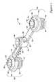
- FIG. 1is a perspective view of an exemplary spinal stabilization system including a transverse connector extending between vertebral anchors;
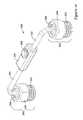
- FIG. 2is a perspective view of the transverse connector shown in FIG. 1 ;
- FIG. 3is a cross-sectional view of the transverse connector of FIG. 1 ;
- FIG. 4is an enlarged perspective view of components of a coupling portion of the transverse connector of FIG. 2 ;
- FIG. 5is a cross-sectional view of components of the coupling portion shown in FIG. 4 ;
- FIG. 6is a cross-sectional view of the components of the coupling portion assembled together
- FIG. 7is a cross-sectional view of the transverse connector of FIG. 2 taken through line 7 - 7 ;
- FIG. 8is a perspective view of another transverse connector for use in a spinal stabilization system
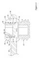
- FIG. 9is a cross-sectional view of the transverse connector of FIG. 8 ;
- FIG. 10is an enlarged perspective view of components of a coupling portion of the transverse connector of FIG. 8 ;
- FIG. 11is a cross-sectional view of components of the coupling portion shown in FIG. 10 ;
- FIG. 12is a top view of the set screw of the transverse connector of FIG. 8 ;
- FIG. 13is a perspective view of another transverse connector for use in a spinal stabilization system
- FIG. 14is a cross-sectional view of the transverse connector of FIG. 13 ;
- FIG. 15is an enlarged perspective view of components of a coupling portion of the transverse connector of FIG. 13 ;
- FIG. 16is a perspective view of yet another transverse connector for use in a spinal stabilization system
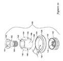
- FIG. 17is a cross-sectional view of the transverse connector of FIG. 16 ;
- FIG. 18is a perspective view of another transverse connector for use in a spinal stabilization system.
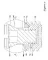
- FIG. 19is a cross-sectional view of the transverse connector of FIG. 18 .
- FIG. 1an exemplary spinal stabilization system 2 for stabilizing a portion of a spinal column, such as one or more spinal segments of a spinal column, is illustrated in FIG. 1 .
- a spinal segmentis intended to refer to two or more vertebrae, the intervertebral disc(s) between the vertebrae and other anatomical elements between the vertebrae.
- a spinal segmentmay include first and second adjacent vertebrae and the intervertebral disc located between the first and second vertebrae.
- the spinal stabilization system 2may provide support to the spinal segment subsequent bone fusion, may help preserve the facet joints between adjacent vertebrae by providing facet offloading and/or may stabilize or reverse neural foraminal narrowing of the spinal column, in some instances.
- the spinal stabilization system 2may be used to treat discogenic low back pain, degenerative spinal stenosis, disc herniations, facet syndrome, posterior element instability, adjacent level syndrome associated with spinal fusion, and/or other maladies associated with the spinal column.
- the spinal stabilization system 2may include one or more or a plurality of vertebral anchors 10 .
- the vertebral anchors 10are depicted as threaded vertebral fasteners (e.g., pedicle screws, bone screws), in some embodiments the vertebral anchors 10 may be vertebral hooks (e.g., laminar hooks) or other types of fastening members for attachment to a bony structure such as a vertebra of the spinal column.
- Each of the vertebral anchors 10may be configured to be secured to a vertebra of a spinal column.
- the spinal stabilization system 2may be used in any desired region of the spinal column, such as the cervical, thoracic, thoracolumbar, and lumbar regions.
- the vertebral stabilization system 2may be installed multi-laterally on opposite sides of the sagittal plane of the spinal column, with the first and third vertebral anchors 10 a , 10 c and the first elongate member 4 positioned on one lateral side of the sagittal plane and the second and fourth vertebral anchors 10 b , 10 d and the second elongate member 4 positioned on the other lateral side (i.e., contra-lateral side) of the sagittal plane.
- first vertebral anchor 10 a and the second vertebral anchor 10 bmay be secured to a first vertebra on contra-lateral sides of the sagittal plane
- third vertebral anchor 10 c and the fourth vertebral anchor 10 dmay be secured to a second vertebra on contra-lateral sides of the sagittal plane.
- Additional vertebral anchors 10may be secured to additional vertebrae as desired.
- the vertebral anchor 10may include a housing 12 and a bone engagement portion, such as a bone screw 14 extending from the housing 12 along a longitudinal axis of the vertebral anchor 10 .
- the vertebral anchor 10may be a monoaxial screw in which the housing 12 is stationary relative to the bone screw 14
- the vertebral anchor 10may be a polyaxial screw in which the housing 12 is actuatable (e.g., pivotable) relative to the bone screw 14
- the bone screw 14may be configured to be installed into a bony region of a vertebra of the spinal column.
- the bone screw 14may be installed into a pedicle of a vertebra, or other region of a vertebra.
- the bone screw 14may include helical threads configured to be screwed into a pedicle of a vertebra, or other bony region of a vertebra.
- the housing 12may include a base portion and first and second legs 8 extending from the base portion and defining a channel 6 , such as a U-shaped channel, therebetween extending into the housing 12 from an upper extent of the housing 12 opposite the bone screw 14 .
- each of the first and second legs 8may include a threaded portion for threadedly engaging a threaded portion of a fastener.
- the first and second legs 8may include other engagement features for engaging with a securing member positioned in the housing 12 between the first and second legs 8 .
- the spinal stabilization system 2may also include one or more, or a plurality of elongate stabilization members 4 , such as elongate rods, extending between vertebral anchors 10 of the spinal stabilization system 2 .
- the spinal stabilization system 2 shown in FIG. 1includes a first elongate member 4 extending between and secured to the first vertebral anchor 10 a and the third vertebral anchor 10 c , and a second elongate member 4 extending between and secured to the second vertebral anchor 10 b and the fourth vertebral anchor 10 d.
- the elongate members 4may be secured in the channels 6 of the housings 12 of the vertebral anchors 10 using threaded fasteners or other securement members.
- threaded set screws 15may be threadably engaged with the threaded portions of the legs 8 of the housings 12 of the third and fourth vertebral anchors 10 c , 10 d and press against the elongate member 4 to secure the elongate members 4 in the channels 6 .
- the spinal stabilization system 2may also include a transverse connector 20 which may be positioned generally perpendicular to the elongate members 4 to provide additional stability to the spinal stabilization system 2 in some instances.
- the transverse connector 20may be configured to be coupled to the housings 12 of contra-laterally positioned vertebral anchors 10 .
- the transverse connector 20may be coupled between the first and second vertebral anchors 10 a , 10 b in an orientation generally perpendicular to the elongate members 4 .
- the transverse connector 20may include fasteners 40 having external threading configured to threadably engage an internal threaded portion of the housing 12 between the legs 8 of a vertebral anchor 10 .
- the fasteners 40may press against the elongate member 4 to secure the elongate members 4 in the channels 6 of the housings 12 of the first and second vertebral anchors 10 a , 10 b.
- the transverse connector 20may extend generally parallel to the elongate member 4 coupled between adjacent vertebral anchors 10 .
- the elongate member 4may be coupled to the first and third vertebral anchors 10 a , 10 c on a single side of the sagittal plane of the spinal column, with the transverse connector 20 also secured to and extending between the first and third vertebral anchors 10 a , 10 c on the same side of the sagittal plane of the spinal column.
- the transverse connector 20may extend parallel to the elongate member 4 in a vertical direction generally parallel with the longitudinal axis of the spinal column.
- the transverse connector 20may include a first connector member 22 and a second connector member 24 coupled together.
- the first connector member 22which may be considered a male connector member, may include a coupling housing 26 and an elongate extension 28 extending from the coupling housing 26 .
- the second connector member 24which may be considered a female connector member, may include a coupling housing 26 and an elongate extension 30 extending from the coupling housing 26 .
- the elongate extension 30may include a receiver 34 with an opening 36 therethrough for receiving the elongate extension 28 of the first connector member 22 .
- the transverse connector 20may be configured such that the first connector member 22 may be moved in multiple degrees of freedom relative to the second connector member 24 .
- the first connector member 22may translate along a longitudinal axis (see arrow A, FIG. 2 ) and rotate about the longitudinal axis (see Arrow B, FIG. 7 ) relative to the second connector member 24 , in some instances.
- the transverse connector 20may include additional degrees of freedom, such as pivot about an axis transverse to the longitudinal axis.
- the locking screw 38When the first connector member 22 is positioned at a desired orientation relative to the second connector member 24 , the locking screw 38 , threadably engaged in a threaded bore of the receiver 34 , may be rotated into engagement against the elongate extension 28 of the first connector member 22 to apply a clamping force between the first connector member 22 and the second connector member 24 to thereby prevent further movement therebetween.
- the locking screw 38may include a protuberance 37 , which may be a spherical protuberance, extending into an elongate recess 32 of the elongate extension 28 of the first connector member 22 .
- the arcuate lower surface of the protuberance 37 , the arcuate surface of the recess 32 and the arcuate lower wall of the opening 36may share a common center of curvature.
- the elongate extension 28 of the first connector member 22may rotate about the common center of curvature relative to the second connector member 24 to adjust the orientation of the first connector member 22 relative to the second connector member 24 .
- the recess 32may include end surfaces which limit the longitudinal travel of the protuberance 37 in the recess 32 , and thus prevent decoupling of the first connector member 22 from the second connector member 24 .
- the transverse connector 20may include coupling assemblies 80 configured to secure the transverse connector 20 to the housings 12 of vertebral anchors 10 . As shown in FIG. 3 , a first coupling assembly 80 proximate the first end of the transverse connector 20 may couple the transverse connector 20 to a first vertebral anchor 10 and a second coupling assembly 80 proximate the second end of the transverse connector 20 may couple the transverse connector 20 to a second vertebral anchor 10 .
- FIG. 4a coupling assembly 80 of the transverse connector 20 will be further described. It is noted that although one coupling assembly 80 at one end of the transverse connector 20 is described herein, the coupling assembly 80 at the other end of the transverse connector 20 may be similarly configured and include similar components.
- the coupling assembly 80may include the coupling housing 26 , the fastener 40 , and a set screw 50 configured to threadably engage a threaded bore 46 of the fastener 40 .
- the fastener 40may include external threading configured to threadably engage an internal threaded portion of the housing 12 of a vertebral anchor 10 , and a spherical upper surface.
- the fastener 40may include a lower threaded portion 42 including the external threading and an upper spherical portion 44 including a spherically convex surface 56 .
- the fastener 40may be a monolithic member including the upper spherical portion 44 and the lower threaded portion 42 .
- the upper spherical portion 44may include a plurality of convex segments 48 with slots 49 therebetween radially arranged. The presence of the slots 49 between adjacent segments 48 may permit the segments 48 of the upper spherical portion 44 to flex or deflect relative to each other.
- the upper spherical portion 44may be configured to be positioned in the aperture 52 of the coupling housing 26 such that the spherically convex surface 56 faces and mates with a spherically concave annular sidewall 54 of the aperture 52 .
- the aperture 52may receive the upper spherical portion 44 of the fastener 40 therein to permit rotational movement therebetween. As shown in FIG.
- the set screw 50may be threadably disposed in the threaded bore 46 to exert a radially outward force F on the convex segments 48 of the upper spherical portion 44 to press the spherically convex surface 56 against the spherically concave surface of the annular sidewall 54 to lock the upper spherical portion 44 in the aperture 52 and prevent further rotational movement therebetween.
- the set screw 50 and the fastener 40may be configured such that the force F exerted on the convex segments 48 from the set screw 50 is substantially radially outward, without appreciable force being generated axially.
- the set screw 50includes an external thread 60 having a major diameter D 1 that is constant from an upper portion of the set screw 50 to a lower portion of the set screw 50 , and a minor diameter that tapers from a larger diameter D 2 proximate the upper portion of the set screw 50 to a smaller diameter D 3 proximate the lower portion of the set screw 50 .
- the height of the thread 60increases from the upper portion to the lower portion of the set screw 50 while the major diameter D 1 remains substantially constant.
- the threaded bore 46 of the upper spherical portion 44 of the fastener 40includes an internal thread 70 that has a major diameter D 4 that is constant from an upper portion of the threaded bore 46 to a lower portion of the threaded bore 46 , and a minor diameter that tapers from a larger diameter D 5 proximate the upper portion of the threaded bore 46 to a smaller diameter D 6 proximate the lower portion of the threaded bore 46 .
- the height of the thread 70increases from the upper portion of the threaded bore 46 to the lower portion of the threaded bore 46 while the major diameter D 4 remains substantially constant.
- the thread 60 of the set screw 50may be configured such that the upper flank 62 of the thread 60 is perpendicular to the central longitudinal axis of the set screw 50 and the lower flank 64 of the thread 60 is perpendicular to the central longitudinal axis of the set screw 50 .
- the upper flank 62may be parallel to the lower flank 64 .
- the crest 66 of the thread 60may be perpendicular to the upper and lower flanks 62 , 64 and the root 68 of the thread 60 may be perpendicular to the upper and lower flanks 62 , 64 .
- the crest 66 and/or root 68 of the thread 60may be parallel to the central longitudinal axis of the set screw 50 .
- the thread 70 of the threaded bore 46may be configured such that the upper flank 72 of the thread 70 is perpendicular to the central longitudinal axis of the threaded bore 46 and the lower flank 74 of the thread 70 is perpendicular to the central longitudinal axis of the threaded bore 46 .
- the upper flank 72may be parallel to the lower flank 74 .
- the crest 76 of the thread 70may be perpendicular to the upper and lower flanks 72 , 74 and the root 78 of the thread 70 may be perpendicular to the upper and lower flanks 72 , 74 .
- the crest 76 and/or root 78 of the thread 70may be parallel to the central longitudinal axis of the threaded bore 46 .
- Such a configurationmay provide positive engagement between the thread 60 of the set screw 50 and the thread 70 of the threaded bore 46 even at the onset of threading the set screw 50 into the threaded bore 46 .
- the thread 60may engage the thread 70 as the set screw 50 initially enters the threaded bore 46 .
- the root 68 of the thread 60 of the set screw 50presses against the crest 76 of the thread 70 of the threaded bore 46 , exerting a radially outward force F normal to the surfaces of the root 68 and crest 76 on the convex segments 48 of the upper spherical portion 44 of the fastener 40 , which in turn presses the convex segments 48 against the concave sidewall 54 of the coupling housing 26 , as shown in FIG. 6 .
- the transverse connector 20may be coupled between first and second vertebral anchors 10 .
- the first and second vertebral anchors 10may be secured to a vertebra, followed by positioning an elongate member 4 in the channel 6 of the housing 12 of each of the vertebral anchors 10 .
- the fastener 40may be threaded into the threaded opening in the housing 12 between the legs 8 of the housing 12 to secure the elongate member 4 in the channel 6 .
- the fastener 40may include an internal driver interface 45 , such as a hex socket, or other driver interface for receiving a driver to rotatably advance the fastener 40 against the elongate member 4 .
- the vertebral anchor 10may include a seat 5 against which the elongate member 4 is pressed against to transfer a locking force to the head 16 of the bone screw 14 to lock the housing 12 from further pivotable movement relative to the bone screw 14 .
- the elongate member 4may be pressed directly against the head 16 of the bone screw 14 . This process may be followed to secure each of the elongate members 4 to the housing 12 of the respective vertebral anchor 10 .
- the first connector member 22may then be coupled to the upper spherical portion 44 of the fastener 40 secured to the first vertebral anchor 10 a and/or the second connector member 24 may be coupled to the upper spherical portion 44 of the fastener 40 secured to the second vertebral anchor 10 b .
- the spherical interface between the spherically convex surface 56 of the upper spherical portion 44 and the spherically concave sidewall 54 of the aperture 52 of the coupling housing 26allows for multi-axial rotation of the transverse connector 20 relative to the housings 12 to permit a desired orientation of the transverse connector 20 .
- the set screw 50may be threadably engaged in the threaded bore 46 of the fastener 40 to apply a radially outward locking force F between the spherically convex surface 56 of the upper spherical portion 44 and the spherically concave sidewall 54 of the aperture 52 of the coupling housing 26 . This may be repeated for each end of the transverse connector 20 to fixedly lock the transverse connector 20 to the housing 12 of each vertebral anchor 10 .
- the locking screw 38may also be tightened once the desired orientation between the first connector member 22 and the second connector member 24 is achieved to fix the first connector member 22 to the second connector member 24 .
- the first and second connector members 22 , 24may be spaced away from direct contact with the housings 12 of the vertebral anchors 10 such that there is a gap between the upper extent of the housings 12 and the coupling housings 26 .
- the transverse connector 120may include a first connector member 122 and a second connector member 124 coupled together.
- the first connector member 122which may be considered a male connector member, may include a coupling housing 126 and an elongate extension 128 extending from the coupling housing 126 .
- the second connector member 124which may be considered a female connector member, may include a coupling housing 126 and an elongate extension 130 extending from the coupling housing 126 .
- the elongate extension 130may include a receiver 134 with an opening 136 therethrough for receiving the elongate extension 128 of the first connector member 122 .
- the transverse connector 120may be configured such that the first connector member 122 may be adjustable relative to the second connector member 124 .
- the first connector member 122may translate along a longitudinal axis relative to the second connector member 124 , in some instances.
- the locking screw 138threadably engaged in a threaded bore of the receiver 134 , may be rotated into engagement against the elongate extension 128 of the first connector member 122 to apply a clamping force between the first connector member 122 and the second connector member 124 to thereby prevent further movement therebetween.
- the locking screw 138may include a protuberance 137 extending into an elongate recess 132 of the elongate extension 128 of the first connector member 122 .
- the recess 132may include end surfaces which limit the longitudinal travel of the protuberance 137 in the recess 132 , and thus prevent decoupling of the first connector member 122 from the second connector member 124 .
- the transverse connector 120may include coupling assemblies 180 configured to secure the transverse connector 120 to the housings 12 of vertebral anchors 10 . As shown in FIG. 9 , a first coupling assembly 180 proximate the first end of the transverse connector 120 may couple the transverse connector 120 to a first vertebral anchor 10 a and a second coupling assembly 180 proximate the second end of the transverse connector 120 may couple the transverse connector 120 to a second vertebral anchor 10 b.
- FIG. 10a coupling assembly 180 of the transverse connector 120 will be further described. It is noted that although one coupling assembly 180 at one end of the transverse connector 120 is described herein, the coupling assembly 180 at the other end of the transverse connector 120 may be similarly configured and include similar components.
- the coupling assembly 180may include the coupling housing 126 , a threaded fastener 142 , a spherical member 144 , and a tapered screw 160 configured to threadably engage a threaded bore 145 of the fastener 142 .
- the fastener 142may include external threading configured to threadably engage an internal threaded portion of the housing 12 of a vertebral anchor 10 to secure an elongate member 4 in the channel 6 of the housing 12 .
- the upper surface of the fastener 142may be a spherically concave upper surface 143 .
- the spherical member 144may include a plurality of convex segments 148 with slots 149 therebetween radially arranged. The presence of the slots 149 between adjacent segments 148 may permit the segments 148 of the spherical member 144 to flex or deflect relative to each other.
- the spherical member 144may be configured to be positioned in the aperture 152 of the coupling housing 126 such that the spherically convex surface 156 faces and mates with a spherically concave annular sidewall 154 of the aperture 152 .
- the aperture 152may receive the spherical member 144 therein to permit rotational movement therebetween.
- the spherically convex surface 156is also configured to rest against and mate with the spherically concave surface 143 of the fastener 142 .
- a tapered screw 160may be inserted through the bore 146 of the spherical member 144 such that a threaded portion 164 of the tapered screw threadably engages the threaded bore 145 of the fastener 142 .
- a tapered head portion 162 of the tapered screw 160may contact a tapered surface 163 of the bore 146 of the spherical member 144 to exert a radially outward force on the convex segments 148 of the spherical member 144 when the tapered screw 160 is threadedably engaged with the fastener 142 .
- the tapered screw 160may include an internal driver interface 161 , such as a hex socket, or other driver interface for receiving a driver to rotatably advance the tapered screw 160 into the threaded bore 145 such that the tapered head portion 162 presses against the tapered surface 153 of the bore 146 .
- an internal driver interface 161such as a hex socket, or other driver interface for receiving a driver to rotatably advance the tapered screw 160 into the threaded bore 145 such that the tapered head portion 162 presses against the tapered surface 153 of the bore 146 .
- the transverse connector 120may be coupled between first and second vertebral anchors 10 .
- the first and second vertebral anchors 10may be secured to a vertebra, followed by positioning an elongate member 4 in the channel 6 of the housing 12 of each of the vertebral anchors 10 .
- the fastener 142may be threaded into the threaded opening in the housing 12 between the legs 8 of the housing 12 to secure the elongate member 4 in the channel 6 .
- the fastener 142may include an internal driver interface, such as a hex socket, or other driver interface formed in the threaded bore 145 for receiving a driver to rotatably advance the fastener 142 against the elongate member 4 .
- an internal driver interfacesuch as a hex socket, or other driver interface formed in the threaded bore 145 for receiving a driver to rotatably advance the fastener 142 against the elongate member 4 .
- the bore 145may be configured with hexagonal sidewalls 149 defining the internal driver interface for receiving a hex wrench.
- the threading of the bore 145may be configured such that the major diameter 147 of the internal threading of the bore 145 circumscribes the hexagonal sidewalls 149 , while the minor diameter 165 of the threaded portion 164 of the tapered screw 160 would be inscribed within the hexagonal sidewalls 149 .
- the driver interfacemay be otherwise configured into the bore 145 while preserving the internal threading for threadably receiving the threaded portion 164 of the tapered screw 160 .
- the spherical member 144rotatably coupled in the coupling housing 126 of the first connector member 122 and/or the second connector member 124 , may then be positioned against the spherically concave upper surface 143 of the fastener 142 secured to the respective vertebral anchor 10 .
- the spherical interface between the spherically convex surface 156 of the spherical member 144 and the spherically concave sidewall 154 of the aperture 152 of the coupling housing 126allows for multi-axial rotation of the transverse connector 120 relative to the housings 12 to permit a desired orientation of the transverse connector 120 .
- the tapered screw 160may be advanced through the bore 146 of the spherical member 144 and threadably engaged in the threaded bore 145 of the fastener 142 to apply a radially outward locking force F between the spherically convex surface 156 of the spherical member 144 and the spherically concave sidewall 154 of the aperture 152 of the coupling housing 126 . This may be repeated for each end of the transverse connector 120 to fixedly lock the transverse connector 120 to the housing 12 of each vertebral anchor 10 .
- the locking screw 138may also be tightened once the desired orientation between the first connector member 122 and the second connector member 124 is achieved to fix the first connector member 122 to the second connector member 124 .
- the first and second connector members 122 , 124may be spaced away from direct contact with the housings 12 of the vertebral anchors 10 such that there is a gap between the upper extent of the housings 12 and the coupling housings 126 .
- the transverse connector 220may include a first coupling housing 226 , a second coupling housing 226 and a cross member 222 pivotably coupled to each of the coupling housings 226 at a pivot point, such as at pins 224 .
- the transverse connector 220may include coupling assemblies 280 configured to secure the transverse connector 220 to the housings 12 of vertebral anchors 10 . As shown in FIG. 14 , a first coupling assembly 280 proximate the first end of the transverse connector 220 may couple the transverse connector 220 to a first vertebral anchor 10 a and a second coupling assembly 280 proximate the second end of the transverse connector 220 may couple the transverse connector 220 to a second vertebral anchor 10 b.
- FIG. 15a coupling assembly 280 of the transverse connector 220 will be further described. It is noted that although one coupling assembly 280 at one end of the transverse connector 220 is described herein, the coupling assembly 280 at the other end of the transverse connector 220 may be similarly configured and include similar components.
- the coupling assembly 280may include the coupling housing 226 , a threaded fastener 242 , and a threaded screw 260 configured to extend through the elongated opening 230 and threadably engage a threaded bore 245 of the fastener 242 .
- the fastener 242may include external threading configured to threadably engage an internal threaded portion of the housing 12 of a vertebral anchor 10 to secure an elongate member 4 in the channel 6 of the housing 12 .
- the upper surface of the fastener 242may be a spherically concave upper surface 243 .
- the coupling housing 226may include an upper surface 228 such as a spherically concave surface, a lower surface 229 such as a spherically convex surface, and an aperture extending through the coupling housing 226 from the upper surface 228 to the lower surface 229 .
- the aperturemay be an elongated opening 230 having a width W and a length L greater than the width W.
- the elongated opening 230may include partial threading 232 along a portion of the sidewall of the elongated opening 230 .
- each of two opposing sidewalls of the elongated opening 230may include discontinuous threads.
- the threaded screw 260may include a head 262 having a driver interface 261 and a shank extending from the head 262 having a threaded lower portion 264 and an unthreaded upper portion 266 .
- the threaded lower portion 264may be sized to pass through the elongate opening 230 of the coupling housing 226 only by way of the partial threads 228 of the elongate opening 230 .
- the major diameter of the threaded lower portion 264may be greater than the width W of the elongate opening 230 such that the threaded lower portion 264 cannot pass freely through the elongate opening 230 in an axial direction without being rotatably threaded through the partial threaded portion of the elongated opening 230 .
- the unthreaded upper portion 266may have a diameter less than the width W of the elongated opening 230 such that once the lower threaded portion 264 is threaded through the elongated opening 230 , the unthreaded upper portion 266 (which is now positioned in the elongated opening 230 ) may freely travel back and forth along the length L of the elongated opening 230 to any desired position.
- the transverse connector 220may be coupled between first and second vertebral anchors 10 .
- the first and second vertebral anchors 10may be secured to a vertebra, followed by positioning an elongate member 4 in the channel 6 of the housing 12 of each of the vertebral anchors 10 .
- the fastener 242may be threaded into the threaded opening in the housing 12 between the legs 8 of the housing 12 to secure the elongate member 4 in the channel 6 .
- the fastener 242may include an internal driver interface, such as a hex socket, or other driver interface formed in the threaded bore 245 for receiving a driver to rotatably advance the fastener 242 against the elongate member 4 .
- an internal driver interfacesuch as a hex socket, or other driver interface formed in the threaded bore 245 for receiving a driver to rotatably advance the fastener 242 against the elongate member 4 .
- the spherically convex lower surface 229 of the coupling housing 226may then be positioned against the spherically concave upper surface 243 of the fastener 242 secured to the respective vertebral anchor 10 , and the threaded screw 260 (extending through the elongated opening 230 ) may be threaded into the threaded bore 245 of the fastener 242 .
- the spherical interface between the spherically convex lower surface 229 of the coupling housing 226 and the spherically concave upper surface 243 of the fastener 242allows for multi-axial rotation of the transverse connector 220 relative to the housings 12 while the unthreaded upper portion 266 of the threaded screw 260 travels along the elongated opening 230 to permit a desired orientation of the transverse connector 220 .
- the under side of the head 262 of the threaded screw 260may be spherically convex to mate with the spherically concave upper surface 228 of the coupling housing 226 .
- the spherical interfaces and elongated opening 230along with the pivotable connection between the coupling housing 226 and the cross member 222 , may allow for a desired degree of lateral adjustability of the transverse connector 220 .
- the threaded screw 260may be rotated in the threaded bore 245 of the fastener 242 to apply a locking force between the spherically convex lower surface 229 of the coupling housing 226 and the spherically concave upper surface 243 of the fastener 242 to lock the coupling housing 226 from further movement relative to the housing 12 .
- Thismay be repeated for each end of the transverse connector 220 to fixedly lock the transverse connector 220 to the housing 12 of each vertebral anchor 10 .
- the coupling housings 226 of the transverse connector 220may be spaced away from direct contact with the housings 12 of the vertebral anchors 10 such that there is a gap between the upper extent of the housings 12 and the coupling housings 226 .
- the transverse connector 320may include a first connector member 322 and a second connector member 324 coupled together.
- the first connector member 322which may be considered a male connector member, may include a first spherical member 348 and an elongate extension 328 extending from the first spherical member 348 .
- the second connector member 324which may be considered a female connector member, may include a second spherical member 348 and an elongate extension 330 extending from the second spherical member 348 .
- the elongate extension 330may include a receiver 334 with an opening extending therein for receiving the elongate extension 328 of the first connector member 322 .
- the transverse connector 320may be configured such that the first connector member 322 may be adjustable relative to the second connector member 324 .
- the first connector member 322may translate along a longitudinal axis relative to the second connector member 324 , in some instances.
- the locking screw 338threadably engaged in a threaded bore of the receiver 334 , may be rotated into engagement against the elongate extension 328 of the first connector member 322 to apply a clamping force between the first connector member 322 and the second connector member 324 to thereby prevent further movement therebetween.
- the transverse connector 320may include coupling assemblies 380 configured to secure the transverse connector 320 to the housings 12 of vertebral anchors 10 . As shown in FIG. 17 , a first coupling assembly 380 proximate the first end of the transverse connector 320 may couple the transverse connector 320 to a first vertebral anchor 10 a and a second coupling assembly 380 proximate the second end of the transverse connector 320 may couple the transverse connector 320 to a second vertebral anchor 10 b.
- a coupling assembly 380may include the spherical member 348 , a threaded fastener 342 , and a threaded nut 346 configured to threadably engage a threaded upper portion of the fastener 342 .
- the fastener 342may also include a lower portion having external threading configured to threadably engage an internal threaded portion of the housing 12 of a vertebral anchor 10 to secure an elongate member 4 in the channel 6 of the housing 12 .
- the upper surface of the fastener 342may be a spherically concave upper surface 343 .
- the threaded nut 346may surround at least a portion of the spherical member 348 with the extension 328 / 330 extending through a bore 350 of the threaded nut 346 .
- the spherical member 348may be sized larger than the bore 350 of the threaded nut 346 such that the spherical member 348 cannot pass through the bore 350 .
- a sidewall of the bore 350 of the nut 346may be configured to engage a portion of the spherical member 348 when the threaded nut 346 is tightened onto the fastener 342 .
- the spherical member 348may include a spherically convex surface 356 configured to rest against and mate with the spherically concave surface 343 of the fastener 342 to provide multi-axial rotational orientation therebetween.
- the transverse connector 320may be coupled between first and second vertebral anchors 10 .
- the first and second vertebral anchors 10may be secured to a vertebra, followed by positioning an elongate member 4 in the channel 6 of the housing 12 of each of the vertebral anchors 10 .
- the fastener 342may be threaded into the threaded opening in the housing 12 between the legs 8 of the housing 12 to secure the elongate member 4 in the channel 6 .
- the fastener 342may include an internal driver interface 345 , such as a hex socket, or other driver interface for receiving a driver to rotatably advance the fastener 342 against the elongate member 4 .
- the spherical member 348may then be positioned against the spherically concave upper surface 343 of the fastener 342 secured to the respective vertebral anchor 10 .
- the spherical interface between the spherically convex surface 356 of the spherical member 348 and the spherically concave upper surface 343allows for multi-axial rotation of the transverse connector 320 relative to the housings 12 to permit a desired orientation of the transverse connector 320 .
- the threaded nut 346may be threadably engaged onto the threaded upper portion of the fastener 342 to apply a locking force between the spherically convex surface 356 of the spherical member 348 and the spherically concave upper surface 343 of the fastener 342 . This may be repeated for each end of the transverse connector 320 to fixedly lock the transverse connector 320 to the housing 12 of each vertebral anchor 10 .
- the locking screw 338may also be tightened once the desired orientation between the first connector member 322 and the second connector member 324 is achieved to fix the first connector member 322 to the second connector member 324 .
- the first and second connector members 322 , 324may be spaced away from direct contact with the housings 12 of the vertebral anchors 10 such that there is a gap between the upper extent of the housings 12 and the threaded nuts 346 .
- a transverse connectorhaving a first end including a coupling assembly for coupling to a housing 12 of a vertebral anchor 10 and a second end including a coupling assembly for coupling directly to an elongate member 4 .
- a transverse connector 420which may be coupled between a vertebral anchor 10 and an elongate member 4 is shown in FIG. 18 .
- the transverse connector 420may include a first connector member 422 and a second connector member 424 coupled together. Similar to transverse connectors discussed above, the transverse connector 420 may be configured such that the first connector member 422 may be adjustable relative to the second connector member 424 .
- the locking screw 438threadably engaged in a threaded bore of the receiver 434 , may be rotated into engagement against the elongate extension 428 of the first connector member 422 to apply a clamping force between the first connector member 422 and the second connector member 424 to thereby prevent further movement therebetween.
- the receiver 434may be associated with the first connector member 422 and the elongate extension 428 may be associated with the second connector member 424 , or the first and second connector members 422 , 424 may otherwise be configured to be adjustably secured to another.
- the transverse connector 420may include a coupling assembly at one end of the transverse connector 420 configured to secure the first end of the transverse connector 420 to the housing 12 of a vertebral anchor 10 and a dissimilar coupling assembly at the other end of the transverse connector 420 configured to secure the second end of the transverse connector 420 to the elongate member 4 .
- the first coupling assembly 480 at the first end of the transverse connector 420may be similar to one of the coupling assemblies described above in regards to the transverse connectors 20 , 120 , 220 , 320 .
- the first coupling assembly 480may be similar to the coupling assembly 80 of the transverse connector 20 , although the coupling assembly 480 may alternatively be constructed similar to the coupling assemblies 180 , 280 , 380 , or other desired construction.
- the first coupling assembly 480is shown associated with the second connector member 424 , in other embodiments the first coupling assembly 480 may be associated with the first connector member 422 .
- the first coupling assembly 480may include a coupling housing 426 , a fastener 440 , and a set screw 450 configured to threadably engage a threaded bore of the fastener 440 .
- the fastener 440may include external threading configured to threadably engage an internal threaded portion of the housing 12 of the vertebral anchor 10 , and a spherical upper surface.
- the fastener 440may include a lower threaded portion 442 including the external threading and an upper spherical portion 444 including a plurality of convex segments 448 with slots therebetween radially arranged which are flexible or deflectable relative to each other.
- the upper spherical portion 444may be configured to be positioned in the aperture of the coupling housing 426 such that the spherically convex surface of the upper spherical portion 444 faces and mates with a spherically concave annular sidewall of the aperture to permit rotational movement therebetween.
- the set screw 450may be threadably disposed in the threaded bore to press the convex segments 448 against the coupling housing 426 to lock the upper spherical portion 444 in the aperture and prevent further rotational movement therebetween.
- the second coupling assembly 490 at the second end of the transverse connector 420may be configured to be secured directly to an elongate member 4 .
- the second coupling assembly 490may include a coupler 492 having a pair of deflectable arms 491 and a threaded portion 494 .
- the coupler 492may be disposed in a bore of a coupling housing 496 .
- a threaded fastener 498may be threadably engaged with the threaded portion 494 of the coupler 492 .
- the deflectable arms 491may be configured to be deflected around the elongate member 4 to couple the elongate member 4 thereto.
- the second coupling assembly 490is shown associated with the first connector member 422 , in other embodiments the second coupling assembly 490 may be associated with the second connector member 424 .
- the first coupling assembly 480 of the transverse connector 420may be coupled to the vertebral anchor 10 as described above.
- the second coupling assembly 490the second coupling assembly 490 of the transverse connector 420 may be coupled to the elongate member 4 by first inserting the elongate member 4 into the cavity between the deflectable arms 491 .
- the elongate member 4may snap into the cavity between the deflectable arms 491 to provisionally lock the elongate member 4 to the second coupling assembly 490 .
- the threaded fastener 498threadably engaged with the threaded portion 494 of the coupler 492 , may then be rotated to draw the coupler 492 upward into the cavity of the coupling housing 496 .
- the deflectable arms 491may press against the coupling housing 496 in the bore to clamp onto the elongate member 4 , thereby securing the coupling housing 490 to the elongate member 4 .
- a locking featuremay be included to prevent the threaded fastener (e.g., fastener 40 , 142 , 242 , 342 , 440 ) from backing out of the housing 12 of the vertebral anchor 10 when subjected to torque exerted by the transverse connector through spinal movement.
- an engaging membere.g., setscrew 50 , 450 , threaded screw 160 , 260 or spherical member 348
- setscrew 50 , 450 , threaded screw 160 , 260 or spherical member 348may be pressed against a feature of the fastener to deform the threads to lock the fastener in place.
- the coupling housingsmay include features designed to insert into or otherwise interact with the channels 6 of the housing 12 or other feature of the housing 12 to prevent relative rotational movement therebetween.
Landscapes
- Health & Medical Sciences (AREA)
- Orthopedic Medicine & Surgery (AREA)
- Life Sciences & Earth Sciences (AREA)
- Neurology (AREA)
- Surgery (AREA)
- Heart & Thoracic Surgery (AREA)
- Engineering & Computer Science (AREA)
- Biomedical Technology (AREA)
- Nuclear Medicine, Radiotherapy & Molecular Imaging (AREA)
- Medical Informatics (AREA)
- Molecular Biology (AREA)
- Animal Behavior & Ethology (AREA)
- General Health & Medical Sciences (AREA)
- Public Health (AREA)
- Veterinary Medicine (AREA)
- Surgical Instruments (AREA)
- Prostheses (AREA)
Abstract
Description
Claims (13)
Priority Applications (3)
| Application Number | Priority Date | Filing Date | Title |
|---|---|---|---|
| US13/041,031US8672978B2 (en) | 2011-03-04 | 2011-03-04 | Transverse connector |
| US14/165,008US20140148858A1 (en) | 2011-03-04 | 2014-01-27 | Transverse connector |
| US15/371,663US20170079686A1 (en) | 2011-03-04 | 2016-12-07 | Transverse connector |
Applications Claiming Priority (1)
| Application Number | Priority Date | Filing Date | Title |
|---|---|---|---|
| US13/041,031US8672978B2 (en) | 2011-03-04 | 2011-03-04 | Transverse connector |
Related Child Applications (1)
| Application Number | Title | Priority Date | Filing Date |
|---|---|---|---|
| US14/165,008ContinuationUS20140148858A1 (en) | 2011-03-04 | 2014-01-27 | Transverse connector |
Publications (2)
| Publication Number | Publication Date |
|---|---|
| US20120226316A1 US20120226316A1 (en) | 2012-09-06 |
| US8672978B2true US8672978B2 (en) | 2014-03-18 |
Family
ID=46753764
Family Applications (3)
| Application Number | Title | Priority Date | Filing Date |
|---|---|---|---|
| US13/041,031Active2031-08-16US8672978B2 (en) | 2011-03-04 | 2011-03-04 | Transverse connector |
| US14/165,008AbandonedUS20140148858A1 (en) | 2011-03-04 | 2014-01-27 | Transverse connector |
| US15/371,663AbandonedUS20170079686A1 (en) | 2011-03-04 | 2016-12-07 | Transverse connector |
Family Applications After (2)
| Application Number | Title | Priority Date | Filing Date |
|---|---|---|---|
| US14/165,008AbandonedUS20140148858A1 (en) | 2011-03-04 | 2014-01-27 | Transverse connector |
| US15/371,663AbandonedUS20170079686A1 (en) | 2011-03-04 | 2016-12-07 | Transverse connector |
Country Status (1)
| Country | Link |
|---|---|
| US (3) | US8672978B2 (en) |
Cited By (22)
| Publication number | Priority date | Publication date | Assignee | Title |
|---|---|---|---|---|
| US20140052189A1 (en)* | 2012-08-15 | 2014-02-20 | Blackstone Medical, Inc. | Pivoting spinal fixation devices |
| US20140128918A1 (en)* | 2012-11-06 | 2014-05-08 | Michael Harper | Polyaxial Cross Connector |
| US20140277159A1 (en)* | 2013-03-14 | 2014-09-18 | DePuy Synthes Products, LLC | Bottom-loading bone anchor assemblies |
| US20140316468A1 (en)* | 2013-04-17 | 2014-10-23 | Ebi, Llc | Cross connector system |
| US9044273B2 (en) | 2013-10-07 | 2015-06-02 | Intelligent Implant Systems, Llc | Polyaxial plate rod system and surgical procedure |
| US20150224610A1 (en)* | 2012-09-24 | 2015-08-13 | Yun-Hyun Chung | Caulking method for preventing piston of hydraulic/pneumatic cylinder from being loosened |
| US20160030091A1 (en)* | 2012-11-06 | 2016-02-04 | Globus Medical, Inc. | Low profile connectors |
| US9421041B2 (en) | 2008-09-09 | 2016-08-23 | Marc E. Richelsoph | Polyaxial screw assembly |
| US9456851B2 (en) | 2007-10-23 | 2016-10-04 | Intelligent Implant Systems, Llc | Spinal implant |
| US20160367292A1 (en)* | 2012-11-06 | 2016-12-22 | Globus Medical, Inc. | Low profile connectors |
| US9763703B2 (en) | 2015-05-05 | 2017-09-19 | Degen Medical, Inc. | Cross connectors, kits, and methods |
| US20170273719A1 (en)* | 2014-01-23 | 2017-09-28 | K2M, Inc. | Spinal stabilization system |
| US20180228516A1 (en)* | 2017-02-14 | 2018-08-16 | Warsaw Orthopedic, Inc. | Spinal implant system and method |
| US10413331B2 (en) | 2016-12-21 | 2019-09-17 | Spine Wave, Inc. | Spinal stabilization system with head to head cross connector |
| US10433873B2 (en) | 2012-09-04 | 2019-10-08 | Zimmer, Inc. | External fixation |
| US20190336178A1 (en)* | 2018-05-03 | 2019-11-07 | K2M, Inc. | Head To Head Transverse Connector |
| US10543019B2 (en) | 2014-08-11 | 2020-01-28 | Zimmer, Inc. | External fixation |
| US10905469B2 (en) | 2012-09-04 | 2021-02-02 | Zimmer, Inc. | External fixation |
| US20210290272A1 (en)* | 2015-12-23 | 2021-09-23 | Xiangyang Ma | Customized posterior atlantoaxial reduction fixatorwith screws and rods |
| US11134988B2 (en) | 2015-06-17 | 2021-10-05 | Zimmer, Inc. | Ankle fixation system |
| US11160587B2 (en)* | 2011-12-08 | 2021-11-02 | Spine Wave, Inc. | Rod connector for attachment to an existing spinal rod |
| US20230240724A1 (en)* | 2019-05-22 | 2023-08-03 | Nuvasive, Inc. | Posterior spinal fixation screws |
Families Citing this family (37)
| Publication number | Priority date | Publication date | Assignee | Title |
|---|---|---|---|---|
| EP2421454A4 (en)* | 2009-04-23 | 2013-12-11 | Spinal Elements Inc | Transverse connectors |
| US9387013B1 (en) | 2011-03-01 | 2016-07-12 | Nuvasive, Inc. | Posterior cervical fixation system |
| US9247964B1 (en)* | 2011-03-01 | 2016-02-02 | Nuasive, Inc. | Spinal Cross-connector |
| WO2012138852A1 (en) | 2011-04-08 | 2012-10-11 | Aesculap Implant Systems, Llc | Articulating rod assembly |
| US8771319B2 (en)* | 2012-04-16 | 2014-07-08 | Aesculap Implant Systems, Llc | Rod to rod cross connector |
| WO2013192489A1 (en)* | 2012-06-21 | 2013-12-27 | Aesculap Implant Systems, Llc | Low profile bone stabilization systems |
| WO2014043254A1 (en)* | 2012-09-11 | 2014-03-20 | Mercy Medical Research Institute | Spinous process fixation device and systems |
| EP2724679A1 (en)* | 2012-10-23 | 2014-04-30 | Nexus Spine, L.L.C. | Transverse connector and related methods |
| US9668779B2 (en)* | 2012-11-05 | 2017-06-06 | Phygen, Llc | Transverse vertebral connector |
| US9023087B2 (en)* | 2012-11-09 | 2015-05-05 | Blackstone Medical, Inc. | Percutaneous modular head-to-head cross connector |
| US9675386B2 (en) | 2013-03-11 | 2017-06-13 | K2M, Inc. | Flexible fastening system |
| US20140277163A1 (en)* | 2013-03-15 | 2014-09-18 | Ryan Kretzer | Reinforcement systems for spine stabilization constructs |
| WO2015023420A2 (en) | 2013-07-25 | 2015-02-19 | Latitude Holdings, Llc | Percutaneous pedicle screw revision system |
| US8911486B1 (en) | 2013-09-16 | 2014-12-16 | Neuraxis, Llc | Implantable devices for thermal therapy and related methods |
| US9308123B2 (en)* | 2013-09-16 | 2016-04-12 | Neuraxis, Llc | Methods and devices for applying localized thermal therapy |
| US20160128734A1 (en)* | 2014-11-11 | 2016-05-12 | Intrepid Orthopedics | Threaded Setscrew Crosslink |
| US20170079687A1 (en)* | 2015-09-22 | 2017-03-23 | Eric Oberlander | Articulating spinal crosslink apparatus |
| US9855078B2 (en)* | 2015-10-05 | 2018-01-02 | Globus Medical, Inc. | Spinal anchoring system |
| US20170105768A1 (en)* | 2015-10-19 | 2017-04-20 | Alphatec Spine, Inc. | Hook inserter |
| US9603634B1 (en) | 2015-11-13 | 2017-03-28 | Amendia, Inc. | Percutaneous rod-to-rod cross connector |
| US10888357B2 (en)* | 2016-02-29 | 2021-01-12 | Warsaw Orthopedic, Inc. | Spinal implant system and method |
| US9962192B2 (en) | 2016-03-17 | 2018-05-08 | Medos International Sarl | Multipoint fixation implants |
| US10321939B2 (en) | 2016-05-18 | 2019-06-18 | Medos International Sarl | Implant connectors and related methods |
| US10517647B2 (en) | 2016-05-18 | 2019-12-31 | Medos International Sarl | Implant connectors and related methods |
| EP3525699B1 (en)* | 2016-10-11 | 2023-07-26 | K2M, Inc. | Spinal implant |
| US10492835B2 (en) | 2016-12-19 | 2019-12-03 | Medos International Sàrl | Offset rods, offset rod connectors, and related methods |
| US10238432B2 (en)* | 2017-02-10 | 2019-03-26 | Medos International Sàrl | Tandem rod connectors and related methods |
| CN106963462A (en)* | 2017-03-23 | 2017-07-21 | 张群 | External fixer for operation on vertebra |
| US10966761B2 (en) | 2017-03-28 | 2021-04-06 | Medos International Sarl | Articulating implant connectors and related methods |
| US10561454B2 (en) | 2017-03-28 | 2020-02-18 | Medos International Sarl | Articulating implant connectors and related methods |
| WO2018187797A1 (en)* | 2017-04-07 | 2018-10-11 | K2M, Inc. | Transverse connector |
| US11648037B2 (en) | 2017-05-03 | 2023-05-16 | Advance Research System, Llc | Extension-ready spinal support system with vascular-safe pedicle screw |
| WO2018204676A1 (en) | 2017-05-03 | 2018-11-08 | Advance Research System, Llc | Extension ready spinal support systems |
| US11076890B2 (en) | 2017-12-01 | 2021-08-03 | Medos International Sàrl | Rod-to-rod connectors having robust rod closure mechanisms and related methods |
| US10898232B2 (en) | 2018-03-20 | 2021-01-26 | Medos International Sàrl | Multipoint fixation implants and related methods |
| US11426210B2 (en) | 2019-09-25 | 2022-08-30 | Medos International Sàrl | Multipoint angled fixation implants for multiple screws and related methods |
| EP4103083B1 (en) | 2020-02-14 | 2024-10-23 | Medos International Sàrl | Integrated multipoint fixation screw |
Citations (76)
| Publication number | Priority date | Publication date | Assignee | Title |
|---|---|---|---|---|
| US4484570A (en) | 1980-05-28 | 1984-11-27 | Synthes Ltd. | Device comprising an implant and screws for fastening said implant to a bone, and a device for connecting two separated pieces of bone |
| US5092867A (en) | 1988-07-13 | 1992-03-03 | Harms Juergen | Correction and supporting apparatus, in particular for the spinal column |
| US5261910A (en) | 1992-02-19 | 1993-11-16 | Acromed Corporation | Apparatus for maintaining spinal elements in a desired spatial relationship |
| US5261907A (en) | 1991-05-17 | 1993-11-16 | Vignaud Jean L | Interconnecting device able to lock spinal osteosynthesis fasteners |
| US5269784A (en) | 1991-12-10 | 1993-12-14 | Synthes (U.S.A.) | Screw nut for plate osteosynthesis |
| US5304179A (en) | 1993-06-17 | 1994-04-19 | Amei Technologies Inc. | System and method for installing a spinal fixation system at variable angles |
| US5397363A (en) | 1992-08-11 | 1995-03-14 | Gelbard; Steven D. | Spinal stabilization implant system |
| US5403316A (en) | 1993-12-02 | 1995-04-04 | Danek Medical, Inc. | Triangular construct for spinal fixation |
| US5498263A (en) | 1994-06-28 | 1996-03-12 | Acromed Corporation | Transverse connector for spinal column corrective devices |
| US5501684A (en) | 1992-06-25 | 1996-03-26 | Synthes (U.S.A.) | Osteosynthetic fixation device |
| US5527314A (en) | 1993-01-04 | 1996-06-18 | Danek Medical, Inc. | Spinal fixation system |
| US5573548A (en)* | 1994-06-09 | 1996-11-12 | Zimmer, Inc. | Suture anchor |
| US5584887A (en) | 1991-08-15 | 1996-12-17 | Smith & Nephew Richards, Inc. | Percutaneous screw adapter |
| US5601554A (en) | 1993-03-04 | 1997-02-11 | Advanced Spine Fixation Systems, Inc. | Branch connector for spinal fixation systems |
| US5693053A (en) | 1995-10-19 | 1997-12-02 | Sdgi Holdings, Inc. | Variable angle and transitional linking member |
| US5709686A (en) | 1995-03-27 | 1998-01-20 | Synthes (U.S.A.) | Bone plate |
| US5713900A (en) | 1996-05-31 | 1998-02-03 | Acromed Corporation | Apparatus for retaining bone portions in a desired spatial relationship |
| US5735853A (en) | 1994-06-17 | 1998-04-07 | Olerud; Sven | Bone screw for osteosynthesis |
| US5800435A (en) | 1996-10-09 | 1998-09-01 | Techsys, Llc | Modular spinal plate for use with modular polyaxial locking pedicle screws |
| US5947966A (en) | 1995-06-06 | 1999-09-07 | Sdgi Holdings, Inc. | Device for linking adjacent rods in spinal instrumentation |
| US5954722A (en) | 1997-07-29 | 1999-09-21 | Depuy Acromed, Inc. | Polyaxial locking plate |
| US5989251A (en) | 1998-06-17 | 1999-11-23 | Surgical Dynamics, Inc. | Apparatus for spinal stabilization |
| US6050997A (en) | 1999-01-25 | 2000-04-18 | Mullane; Thomas S. | Spinal fixation system |
| US6077262A (en) | 1993-06-04 | 2000-06-20 | Synthes (U.S.A.) | Posterior spinal implant |
| US6096039A (en) | 1998-05-13 | 2000-08-01 | Howmedica Gmbh | Means for interconnecting two spaced elongated rods of a human spine implant |
| US6235033B1 (en) | 2000-04-19 | 2001-05-22 | Synthes (Usa) | Bone fixation assembly |
| US6238396B1 (en) | 1999-10-07 | 2001-05-29 | Blackstone Medical, Inc. | Surgical cross-connecting apparatus and related methods |
| US6283967B1 (en) | 1999-12-17 | 2001-09-04 | Synthes (U.S.A.) | Transconnector for coupling spinal rods |
| US6454769B2 (en) | 1997-08-04 | 2002-09-24 | Spinal Concepts, Inc. | System and method for stabilizing the human spine with a bone plate |
| US20020138077A1 (en) | 2001-03-26 | 2002-09-26 | Ferree Bret A. | Spinal alignment apparatus and methods |
| US20020169448A1 (en) | 1999-07-01 | 2002-11-14 | Vanacker Gerard M. | Connector for an osteosynthesis system intended to provide a connection between two rods of a spinal osteosynthesis system, osteosynthesis system using such a connector, and method of implanting such an osteosynthesis system |
| US6485491B1 (en)* | 2000-09-15 | 2002-11-26 | Sdgi Holdings, Inc. | Posterior fixation system |
| US6530929B1 (en) | 1999-10-20 | 2003-03-11 | Sdgi Holdings, Inc. | Instruments for stabilization of bony structures |
| US6616668B2 (en) | 2000-06-09 | 2003-09-09 | Cross Medical Products, Inc. | Adjustable transverse connector for use with a spinal implant system |
| US6641583B2 (en) | 2001-03-29 | 2003-11-04 | Endius Incorporated | Apparatus for retaining bone portions in a desired spatial relationship |
| US20030208204A1 (en)* | 2001-04-17 | 2003-11-06 | Bailey Kirk J. | Anterior cervical plating system |
| US6669701B2 (en) | 2000-01-27 | 2003-12-30 | Synthes (Usa) | Bone plate |
| US6679883B2 (en) | 2001-10-31 | 2004-01-20 | Ortho Development Corporation | Cervical plate for stabilizing the human spine |
| US6682529B2 (en) | 2002-06-11 | 2004-01-27 | Stahurski Consulting, Inc. | Connector assembly with multidimensional accommodation and associated method |
| US6689133B2 (en) | 1999-04-16 | 2004-02-10 | Sdgi Holdings, Inc. | Multi-axial bone anchor system |
| US6719759B2 (en) | 1999-03-09 | 2004-04-13 | Synthes Ag Chur | Bone plate |
| US6761721B2 (en) | 2000-01-24 | 2004-07-13 | Depuy Acromed, Inc. | Transverse connector |
| US20050192578A1 (en) | 2004-02-26 | 2005-09-01 | Horst Steven P. | Bone plates with locking apertures |
| US6945972B2 (en) | 2000-08-24 | 2005-09-20 | Synthes | Apparatus for connecting a bone fastener to a longitudinal rod |
| US20060009773A1 (en)* | 2002-09-06 | 2006-01-12 | Jackson Roger P | Helical interlocking mating guide and advancement structure |
| US7048739B2 (en)* | 2002-12-31 | 2006-05-23 | Depuy Spine, Inc. | Bone plate and resilient screw system allowing bi-directional assembly |
| US20060149265A1 (en)* | 2004-09-07 | 2006-07-06 | Anthony James | Minimal thickness bone plate locking mechanism |
| US20060206208A1 (en)* | 1999-05-05 | 2006-09-14 | Sdgi Holdings, Inc. | Push-in interbody spinal fusion implant with multi-lock for locking opposed screws and method for use thereof |
| US7118303B2 (en) | 2003-12-10 | 2006-10-10 | Zimmer Spine, Inc. | Internally disposed linear fastener system |
| US20060264936A1 (en)* | 2004-11-30 | 2006-11-23 | Partin Jason I | Systems and methods for bone fixation |
| US7160301B2 (en) | 2003-07-01 | 2007-01-09 | Seaspine, Inc. | Transverse connector system |
| US7276069B2 (en) | 2001-01-12 | 2007-10-02 | Biedermann Motech Gmbh | Connector element for bone rods or spinal rods |
| US20070270809A1 (en) | 2006-04-10 | 2007-11-22 | Sdgi Holdings, Inc. | Crosslink interconnection of bone attachment devices |
| US20080021464A1 (en) | 2006-07-19 | 2008-01-24 | Joshua Morin | System and method for a spinal implant locking assembly |
| WO2008039777A2 (en) | 2006-09-26 | 2008-04-03 | Synthes Usa, Llc | Transconnector |
| US20080269751A1 (en)* | 2007-01-11 | 2008-10-30 | Anthem Orthopaedics Llc | Percutaneous intramedullary bone repair device and method for using same |
| US20090043339A1 (en) | 2007-05-22 | 2009-02-12 | K2M, Inc. | Universal transverse connector device |
| US7491221B2 (en) | 2004-03-23 | 2009-02-17 | Stryker Spine | Modular polyaxial bone screw and plate |
| US20090088807A1 (en) | 2007-09-27 | 2009-04-02 | Castaneda Javier E | Locking Screw System With Relatively Hard Spiked Polyaxial Bushing |
| US7569070B2 (en) | 2002-09-12 | 2009-08-04 | Showa Ika Kohgyo Co., Ltd. | Rod connector |
| US20090228046A1 (en) | 2008-03-04 | 2009-09-10 | Laszlo Garamszegi | Transverse vertebral connector |
| US20090254123A1 (en) | 2003-12-31 | 2009-10-08 | Spine Wave, Inc. | Dynamic Spinal Stabilization System |
| US7615068B2 (en) | 2003-05-02 | 2009-11-10 | Applied Spine Technologies, Inc. | Mounting mechanisms for pedicle screws and related assemblies |
| US7635379B2 (en) | 2003-05-02 | 2009-12-22 | Applied Spine Technologies, Inc. | Pedicle screw assembly with bearing surfaces |
| US7645294B2 (en) | 2004-03-31 | 2010-01-12 | Depuy Spine, Inc. | Head-to-head connector spinal fixation system |
| US20100057131A1 (en) | 2008-08-29 | 2010-03-04 | Abbott Spine Inc. | Polyaxial transverse connector |
| US7678136B2 (en) | 2002-02-04 | 2010-03-16 | Spinal, Llc | Spinal fixation assembly |
| US20100087867A1 (en) | 2008-10-03 | 2010-04-08 | Assaf Klein | Fastener assembly that fastens to pedicle screw |
| US7717939B2 (en) | 2004-03-31 | 2010-05-18 | Depuy Spine, Inc. | Rod attachment for head to head cross connector |
| US20100160981A1 (en) | 2008-12-22 | 2010-06-24 | Butler Michael S | Posterior Cervical Cross Connector Assemblies |
| US7744635B2 (en) | 2004-06-09 | 2010-06-29 | Spinal Generations, Llc | Spinal fixation system |
| US7776076B2 (en) | 2004-05-11 | 2010-08-17 | Synthes Usa, Llc | Bone plate |
| US20100211116A1 (en)* | 2009-02-13 | 2010-08-19 | Sean Suh | Orthopedic Anchor Assembly |
| US7780704B2 (en) | 2006-03-10 | 2010-08-24 | Custom Spine, Inc. | Spinal cross-connector |
| US8267978B2 (en)* | 2006-09-14 | 2012-09-18 | Warsaw Orthopedic, Inc. | Hybrid bone fixation apparatus |
| US8480716B2 (en)* | 2008-04-25 | 2013-07-09 | Pioneer Surgical Technology, Inc. | Bone plate system |
Family Cites Families (12)
| Publication number | Priority date | Publication date | Assignee | Title |
|---|---|---|---|---|
| FR2805147B1 (en)* | 2000-02-21 | 2004-03-05 | Jean Jacques Martin | EXTERNAL FIXER FOR IMMOBILIZING BONE PARTS, ESPECIALLY AT THE WRIST |
| FR2816195B1 (en)* | 2000-11-07 | 2003-01-03 | Medicrea | VERTEBRAL ARTHRODESIS MATERIAL |
| US20040243128A1 (en)* | 2001-05-17 | 2004-12-02 | Howland Robert S. | Selective axis posterior lumbar spinal plating fixation apparatus and methods for use |
| DE10152094C2 (en)* | 2001-10-23 | 2003-11-27 | Biedermann Motech Gmbh | Bone fixation device |
| BRPI0408769A (en)* | 2003-03-26 | 2006-03-28 | Swiss Orthopedic Solutions Sa | lock bone plate |
| US7513905B2 (en)* | 2004-11-03 | 2009-04-07 | Jackson Roger P | Polyaxial bone screw |
| US7837714B2 (en)* | 2006-04-10 | 2010-11-23 | Warsaw Orthopedic, Inc. | Methods and devices for the interconnection of bone attachment devices |
| US7976567B2 (en)* | 2006-10-18 | 2011-07-12 | Warsaw Orthopedic, Inc. | Orthopedic revision connector |
| US8147491B2 (en)* | 2007-06-27 | 2012-04-03 | Vilex In Tennessee, Inc. | Multi-angle clamp |
| US20090076549A1 (en)* | 2007-09-17 | 2009-03-19 | Warsaw Orthopedic, Inc. | Orthopedic implant system |
| EP2248479B1 (en)* | 2009-05-06 | 2012-09-19 | Greatbatch Ltd. | Bone plate assembly |
| US8523911B2 (en)* | 2010-09-16 | 2013-09-03 | Globus Medical, Inc. | Transverse connector including locking cap with bearing surface |
- 2011
- 2011-03-04USUS13/041,031patent/US8672978B2/enactiveActive
- 2014
- 2014-01-27USUS14/165,008patent/US20140148858A1/ennot_activeAbandoned
- 2016
- 2016-12-07USUS15/371,663patent/US20170079686A1/ennot_activeAbandoned
Patent Citations (87)
| Publication number | Priority date | Publication date | Assignee | Title |
|---|---|---|---|---|
| US4484570A (en) | 1980-05-28 | 1984-11-27 | Synthes Ltd. | Device comprising an implant and screws for fastening said implant to a bone, and a device for connecting two separated pieces of bone |
| US5092867A (en) | 1988-07-13 | 1992-03-03 | Harms Juergen | Correction and supporting apparatus, in particular for the spinal column |
| US5261907A (en) | 1991-05-17 | 1993-11-16 | Vignaud Jean L | Interconnecting device able to lock spinal osteosynthesis fasteners |
| US5584887A (en) | 1991-08-15 | 1996-12-17 | Smith & Nephew Richards, Inc. | Percutaneous screw adapter |
| US5269784A (en) | 1991-12-10 | 1993-12-14 | Synthes (U.S.A.) | Screw nut for plate osteosynthesis |
| US5261910A (en) | 1992-02-19 | 1993-11-16 | Acromed Corporation | Apparatus for maintaining spinal elements in a desired spatial relationship |
| US5501684A (en) | 1992-06-25 | 1996-03-26 | Synthes (U.S.A.) | Osteosynthetic fixation device |
| US5397363A (en) | 1992-08-11 | 1995-03-14 | Gelbard; Steven D. | Spinal stabilization implant system |
| US5527314A (en) | 1993-01-04 | 1996-06-18 | Danek Medical, Inc. | Spinal fixation system |
| US5601554A (en) | 1993-03-04 | 1997-02-11 | Advanced Spine Fixation Systems, Inc. | Branch connector for spinal fixation systems |
| US6077262A (en) | 1993-06-04 | 2000-06-20 | Synthes (U.S.A.) | Posterior spinal implant |
| US5304179A (en) | 1993-06-17 | 1994-04-19 | Amei Technologies Inc. | System and method for installing a spinal fixation system at variable angles |
| US5403316A (en) | 1993-12-02 | 1995-04-04 | Danek Medical, Inc. | Triangular construct for spinal fixation |
| US5573548A (en)* | 1994-06-09 | 1996-11-12 | Zimmer, Inc. | Suture anchor |
| US5735853A (en) | 1994-06-17 | 1998-04-07 | Olerud; Sven | Bone screw for osteosynthesis |
| US5498263A (en) | 1994-06-28 | 1996-03-12 | Acromed Corporation | Transverse connector for spinal column corrective devices |
| US5709686A (en) | 1995-03-27 | 1998-01-20 | Synthes (U.S.A.) | Bone plate |
| US5947966A (en) | 1995-06-06 | 1999-09-07 | Sdgi Holdings, Inc. | Device for linking adjacent rods in spinal instrumentation |
| US5693053A (en) | 1995-10-19 | 1997-12-02 | Sdgi Holdings, Inc. | Variable angle and transitional linking member |
| US5713900A (en) | 1996-05-31 | 1998-02-03 | Acromed Corporation | Apparatus for retaining bone portions in a desired spatial relationship |
| US5800435A (en) | 1996-10-09 | 1998-09-01 | Techsys, Llc | Modular spinal plate for use with modular polyaxial locking pedicle screws |
| US5954722A (en) | 1997-07-29 | 1999-09-21 | Depuy Acromed, Inc. | Polyaxial locking plate |
| US6454769B2 (en) | 1997-08-04 | 2002-09-24 | Spinal Concepts, Inc. | System and method for stabilizing the human spine with a bone plate |
| US6096039A (en) | 1998-05-13 | 2000-08-01 | Howmedica Gmbh | Means for interconnecting two spaced elongated rods of a human spine implant |
| US5989251A (en) | 1998-06-17 | 1999-11-23 | Surgical Dynamics, Inc. | Apparatus for spinal stabilization |
| US6050997A (en) | 1999-01-25 | 2000-04-18 | Mullane; Thomas S. | Spinal fixation system |
| US6719759B2 (en) | 1999-03-09 | 2004-04-13 | Synthes Ag Chur | Bone plate |
| US6689133B2 (en) | 1999-04-16 | 2004-02-10 | Sdgi Holdings, Inc. | Multi-axial bone anchor system |
| US20060206208A1 (en)* | 1999-05-05 | 2006-09-14 | Sdgi Holdings, Inc. | Push-in interbody spinal fusion implant with multi-lock for locking opposed screws and method for use thereof |
| US20020169448A1 (en) | 1999-07-01 | 2002-11-14 | Vanacker Gerard M. | Connector for an osteosynthesis system intended to provide a connection between two rods of a spinal osteosynthesis system, osteosynthesis system using such a connector, and method of implanting such an osteosynthesis system |
| US6238396B1 (en) | 1999-10-07 | 2001-05-29 | Blackstone Medical, Inc. | Surgical cross-connecting apparatus and related methods |
| US6530929B1 (en) | 1999-10-20 | 2003-03-11 | Sdgi Holdings, Inc. | Instruments for stabilization of bony structures |
| US6283967B1 (en) | 1999-12-17 | 2001-09-04 | Synthes (U.S.A.) | Transconnector for coupling spinal rods |
| US6736817B2 (en) | 1999-12-17 | 2004-05-18 | Thomas N. Troxell | Transconnector for coupling spinal rods |
| US7137986B2 (en) | 1999-12-17 | 2006-11-21 | Synthes (U.S.A.) | Transconnector for coupling spinal rods |
| US6761721B2 (en) | 2000-01-24 | 2004-07-13 | Depuy Acromed, Inc. | Transverse connector |
| US7354441B2 (en) | 2000-01-27 | 2008-04-08 | Synthes (U.S.A.) | Bone plate |
| US6669701B2 (en) | 2000-01-27 | 2003-12-30 | Synthes (Usa) | Bone plate |
| US6235033B1 (en) | 2000-04-19 | 2001-05-22 | Synthes (Usa) | Bone fixation assembly |
| US6616668B2 (en) | 2000-06-09 | 2003-09-09 | Cross Medical Products, Inc. | Adjustable transverse connector for use with a spinal implant system |
| US6945972B2 (en) | 2000-08-24 | 2005-09-20 | Synthes | Apparatus for connecting a bone fastener to a longitudinal rod |
| US20050251141A1 (en)* | 2000-08-24 | 2005-11-10 | Synthes Usa | Apparatus for connecting a bone fastener to a longitudinal rod |
| US6485491B1 (en)* | 2000-09-15 | 2002-11-26 | Sdgi Holdings, Inc. | Posterior fixation system |
| US7276069B2 (en) | 2001-01-12 | 2007-10-02 | Biedermann Motech Gmbh | Connector element for bone rods or spinal rods |
| US20020138077A1 (en) | 2001-03-26 | 2002-09-26 | Ferree Bret A. | Spinal alignment apparatus and methods |
| US6641583B2 (en) | 2001-03-29 | 2003-11-04 | Endius Incorporated | Apparatus for retaining bone portions in a desired spatial relationship |
| US20030208204A1 (en)* | 2001-04-17 | 2003-11-06 | Bailey Kirk J. | Anterior cervical plating system |
| US6679883B2 (en) | 2001-10-31 | 2004-01-20 | Ortho Development Corporation | Cervical plate for stabilizing the human spine |
| US7678136B2 (en) | 2002-02-04 | 2010-03-16 | Spinal, Llc | Spinal fixation assembly |
| US6682529B2 (en) | 2002-06-11 | 2004-01-27 | Stahurski Consulting, Inc. | Connector assembly with multidimensional accommodation and associated method |
| US20060009773A1 (en)* | 2002-09-06 | 2006-01-12 | Jackson Roger P | Helical interlocking mating guide and advancement structure |
| US7569070B2 (en) | 2002-09-12 | 2009-08-04 | Showa Ika Kohgyo Co., Ltd. | Rod connector |
| US7048739B2 (en)* | 2002-12-31 | 2006-05-23 | Depuy Spine, Inc. | Bone plate and resilient screw system allowing bi-directional assembly |
| US7635379B2 (en) | 2003-05-02 | 2009-12-22 | Applied Spine Technologies, Inc. | Pedicle screw assembly with bearing surfaces |
| US7615068B2 (en) | 2003-05-02 | 2009-11-10 | Applied Spine Technologies, Inc. | Mounting mechanisms for pedicle screws and related assemblies |
| US7160301B2 (en) | 2003-07-01 | 2007-01-09 | Seaspine, Inc. | Transverse connector system |
| US7118303B2 (en) | 2003-12-10 | 2006-10-10 | Zimmer Spine, Inc. | Internally disposed linear fastener system |
| US7334961B2 (en) | 2003-12-10 | 2008-02-26 | Zimmer Spine, Inc. | Internally disposed linear fastener system |
| US20090254123A1 (en) | 2003-12-31 | 2009-10-08 | Spine Wave, Inc. | Dynamic Spinal Stabilization System |
| US20050192578A1 (en) | 2004-02-26 | 2005-09-01 | Horst Steven P. | Bone plates with locking apertures |
| US7491221B2 (en) | 2004-03-23 | 2009-02-17 | Stryker Spine | Modular polyaxial bone screw and plate |
| US20100036420A1 (en) | 2004-03-31 | 2010-02-11 | Depuy Spine, Inc. | Head-to-head connector spinal fixation system |
| US7717939B2 (en) | 2004-03-31 | 2010-05-18 | Depuy Spine, Inc. | Rod attachment for head to head cross connector |
| US7645294B2 (en) | 2004-03-31 | 2010-01-12 | Depuy Spine, Inc. | Head-to-head connector spinal fixation system |
| US7776076B2 (en) | 2004-05-11 | 2010-08-17 | Synthes Usa, Llc | Bone plate |
| US7744635B2 (en) | 2004-06-09 | 2010-06-29 | Spinal Generations, Llc | Spinal fixation system |
| US20060149265A1 (en)* | 2004-09-07 | 2006-07-06 | Anthony James | Minimal thickness bone plate locking mechanism |
| US20060264936A1 (en)* | 2004-11-30 | 2006-11-23 | Partin Jason I | Systems and methods for bone fixation |
| US7780704B2 (en) | 2006-03-10 | 2010-08-24 | Custom Spine, Inc. | Spinal cross-connector |
| US7722648B2 (en) | 2006-04-10 | 2010-05-25 | Warsaw Orthopedic, Inc. | Crosslink interconnection of bone attachment devices |
| US20070270809A1 (en) | 2006-04-10 | 2007-11-22 | Sdgi Holdings, Inc. | Crosslink interconnection of bone attachment devices |
| US20080021464A1 (en) | 2006-07-19 | 2008-01-24 | Joshua Morin | System and method for a spinal implant locking assembly |
| US8267978B2 (en)* | 2006-09-14 | 2012-09-18 | Warsaw Orthopedic, Inc. | Hybrid bone fixation apparatus |
| US20100094345A1 (en) | 2006-09-26 | 2010-04-15 | Sean Saidha | Transconnector |
| WO2008039777A2 (en) | 2006-09-26 | 2008-04-03 | Synthes Usa, Llc | Transconnector |
| WO2008039777A3 (en) | 2006-09-26 | 2008-09-18 | Synthes Usa | Transconnector |
| US20080269751A1 (en)* | 2007-01-11 | 2008-10-30 | Anthem Orthopaedics Llc | Percutaneous intramedullary bone repair device and method for using same |
| US8211108B2 (en)* | 2007-01-11 | 2012-07-03 | Anthem Orthopaedics Llc | Percutaneous intramedullary bone repair device |
| US20090043339A1 (en) | 2007-05-22 | 2009-02-12 | K2M, Inc. | Universal transverse connector device |
| US20090088807A1 (en) | 2007-09-27 | 2009-04-02 | Castaneda Javier E | Locking Screw System With Relatively Hard Spiked Polyaxial Bushing |
| US20090228046A1 (en) | 2008-03-04 | 2009-09-10 | Laszlo Garamszegi | Transverse vertebral connector |
| US8480716B2 (en)* | 2008-04-25 | 2013-07-09 | Pioneer Surgical Technology, Inc. | Bone plate system |
| US20100057131A1 (en) | 2008-08-29 | 2010-03-04 | Abbott Spine Inc. | Polyaxial transverse connector |
| US20100087867A1 (en) | 2008-10-03 | 2010-04-08 | Assaf Klein | Fastener assembly that fastens to pedicle screw |
| US20100160981A1 (en) | 2008-12-22 | 2010-06-24 | Butler Michael S | Posterior Cervical Cross Connector Assemblies |
| US8246665B2 (en)* | 2008-12-22 | 2012-08-21 | Life Spine, Inc. | Posterior cervical cross connector assemblies |
| US20100211116A1 (en)* | 2009-02-13 | 2010-08-19 | Sean Suh | Orthopedic Anchor Assembly |
Cited By (40)
| Publication number | Priority date | Publication date | Assignee | Title |
|---|---|---|---|---|
| US9456851B2 (en) | 2007-10-23 | 2016-10-04 | Intelligent Implant Systems, Llc | Spinal implant |
| US9603629B2 (en) | 2008-09-09 | 2017-03-28 | Intelligent Implant Systems Llc | Polyaxial screw assembly |
| US9421041B2 (en) | 2008-09-09 | 2016-08-23 | Marc E. Richelsoph | Polyaxial screw assembly |
| US9433440B2 (en) | 2008-09-09 | 2016-09-06 | Intelligent Implant Systems Llc | Polyaxial screw assembly |
| US11160587B2 (en)* | 2011-12-08 | 2021-11-02 | Spine Wave, Inc. | Rod connector for attachment to an existing spinal rod |
| US9510866B2 (en)* | 2012-08-15 | 2016-12-06 | Blackstone Medical, Inc. | Pivoting spinal fixation devices |
| US20140052189A1 (en)* | 2012-08-15 | 2014-02-20 | Blackstone Medical, Inc. | Pivoting spinal fixation devices |
| US10433873B2 (en) | 2012-09-04 | 2019-10-08 | Zimmer, Inc. | External fixation |
| US10905469B2 (en) | 2012-09-04 | 2021-02-02 | Zimmer, Inc. | External fixation |
| US20150224610A1 (en)* | 2012-09-24 | 2015-08-13 | Yun-Hyun Chung | Caulking method for preventing piston of hydraulic/pneumatic cylinder from being loosened |
| US9522445B2 (en)* | 2012-09-24 | 2016-12-20 | Volvo Construction Equipment Ab | Caulking method for preventing piston of hydraulic/pneumatic cylinder from being loosened |
| US9072547B2 (en)* | 2012-11-06 | 2015-07-07 | Globus Medical, Inc. | Polyaxial cross connector |
| US9517090B2 (en) | 2012-11-06 | 2016-12-13 | Globus Medical, Inc. | Polyaxial cross connector |
| US20160030091A1 (en)* | 2012-11-06 | 2016-02-04 | Globus Medical, Inc. | Low profile connectors |
| US20160367292A1 (en)* | 2012-11-06 | 2016-12-22 | Globus Medical, Inc. | Low profile connectors |
| US10485587B2 (en)* | 2012-11-06 | 2019-11-26 | Globus Medical, Inc | Low profile connectors |
| US20140128918A1 (en)* | 2012-11-06 | 2014-05-08 | Michael Harper | Polyaxial Cross Connector |
| US10335206B2 (en)* | 2012-11-06 | 2019-07-02 | Globus Medical, Inc. | Low profile connectors |
| US9498254B2 (en) | 2013-03-14 | 2016-11-22 | Medos International Sarl | Bottom-loading bone anchor assemblies |
| US20140277159A1 (en)* | 2013-03-14 | 2014-09-18 | DePuy Synthes Products, LLC | Bottom-loading bone anchor assemblies |
| US9855079B2 (en)* | 2013-04-17 | 2018-01-02 | Ebi, Llc | Cross connector system |
| US20140316468A1 (en)* | 2013-04-17 | 2014-10-23 | Ebi, Llc | Cross connector system |
| US10376289B2 (en) | 2013-04-17 | 2019-08-13 | Zimmer Biomet Spine, Inc. | Cross connector system |
| US9044273B2 (en) | 2013-10-07 | 2015-06-02 | Intelligent Implant Systems, Llc | Polyaxial plate rod system and surgical procedure |
| US9956010B2 (en) | 2013-10-07 | 2018-05-01 | Intelligent Implant Systems, Llc | Polyaxial plate rod system and surgical procedure |
| US9526531B2 (en) | 2013-10-07 | 2016-12-27 | Intelligent Implant Systems, Llc | Polyaxial plate rod system and surgical procedure |
| US20170273719A1 (en)* | 2014-01-23 | 2017-09-28 | K2M, Inc. | Spinal stabilization system |
| US10624675B2 (en)* | 2014-01-23 | 2020-04-21 | K2M, Inc. | Spinal stabilization system |
| US10543019B2 (en) | 2014-08-11 | 2020-01-28 | Zimmer, Inc. | External fixation |
| US9763703B2 (en) | 2015-05-05 | 2017-09-19 | Degen Medical, Inc. | Cross connectors, kits, and methods |
| US11134988B2 (en) | 2015-06-17 | 2021-10-05 | Zimmer, Inc. | Ankle fixation system |
| US20210290272A1 (en)* | 2015-12-23 | 2021-09-23 | Xiangyang Ma | Customized posterior atlantoaxial reduction fixatorwith screws and rods |
| US12150678B2 (en)* | 2015-12-23 | 2024-11-26 | Xiangyang Ma | Customized posterior atlantoaxial reduction fixatorwith screws and rods |
| US10413331B2 (en) | 2016-12-21 | 2019-09-17 | Spine Wave, Inc. | Spinal stabilization system with head to head cross connector |
| US11395684B2 (en) | 2016-12-21 | 2022-07-26 | Spine Wave, Inc. | Head to head cross connector |
| US20180228516A1 (en)* | 2017-02-14 | 2018-08-16 | Warsaw Orthopedic, Inc. | Spinal implant system and method |
| US10993746B2 (en)* | 2018-05-03 | 2021-05-04 | K2M, Inc. | Head to head transverse connector |
| US20190336178A1 (en)* | 2018-05-03 | 2019-11-07 | K2M, Inc. | Head To Head Transverse Connector |
| US11911077B2 (en) | 2018-05-03 | 2024-02-27 | K2M, Inc. | Head to head transverse connector |
| US20230240724A1 (en)* | 2019-05-22 | 2023-08-03 | Nuvasive, Inc. | Posterior spinal fixation screws |
Also Published As
| Publication number | Publication date |
|---|---|
| US20140148858A1 (en) | 2014-05-29 |
| US20170079686A1 (en) | 2017-03-23 |
| US20120226316A1 (en) | 2012-09-06 |
Similar Documents
| Publication | Publication Date | Title |
|---|---|---|
| US8672978B2 (en) | Transverse connector | |
| US9737341B2 (en) | Transverse connector | |
| US8382809B2 (en) | Poly-axial pedicle screw implements and lock screw therefor | |
| US8382803B2 (en) | Vertebral stabilization transition connector | |
| US8252025B2 (en) | Vertebral fixation system | |
| US8439923B2 (en) | Poly-axial pedicle screw assembly | |
| US8870922B2 (en) | Clamp for spinal cross connecting device | |
| EP2769692B1 (en) | Iliosacral polyaxial screw | |
| US7922748B2 (en) | Removable polyaxial housing for a pedicle screw | |
| US7896902B2 (en) | Multi-axial double locking bone screw assembly | |
| US20110009906A1 (en) | Vertebral stabilization transition connector | |
| US20050277928A1 (en) | Spinal implant fixation assembly | |
| US20050283157A1 (en) | Multi-axial bone attachment assembly | |
| WO2007040553A1 (en) | Hybrid jointed bone screw system | |
| US20190388124A1 (en) | Uniplanar screw |
Legal Events
| Date | Code | Title | Description |
|---|---|---|---|
| AS | Assignment | Owner name:ZIMMER SPINE, INC., MINNESOTA Free format text:ASSIGNMENT OF ASSIGNORS INTEREST;ASSIGNORS:DANT, JACK;BARGSTEN, CHRISTOPHER;SCHULTE, PETER;AND OTHERS;SIGNING DATES FROM 20110222 TO 20110304;REEL/FRAME:025905/0236 | |
| STCF | Information on status: patent grant | Free format text:PATENTED CASE | |
| MAFP | Maintenance fee payment | Free format text:PAYMENT OF MAINTENANCE FEE, 4TH YEAR, LARGE ENTITY (ORIGINAL EVENT CODE: M1551) Year of fee payment:4 | |
| MAFP | Maintenance fee payment | Free format text:PAYMENT OF MAINTENANCE FEE, 8TH YEAR, LARGE ENTITY (ORIGINAL EVENT CODE: M1552); ENTITY STATUS OF PATENT OWNER: LARGE ENTITY Year of fee payment:8 | |
| AS | Assignment | Owner name:ZIMMER BIOMET SPINE, INC., INDIANA Free format text:MERGER;ASSIGNOR:ZIMMER SPINE, INC.;REEL/FRAME:059232/0356 Effective date:20160930 | |
| AS | Assignment | Owner name:JPMORGAN CHASE BANK, N.A., AS ADMINISTRATIVE AGENT, NEW YORK Free format text:SECURITY INTEREST;ASSIGNORS:BIOMET 3I, LLC;EBI, LLC;ZIMMER BIOMET SPINE, INC.;AND OTHERS;REEL/FRAME:059293/0213 Effective date:20220228 | |
| AS | Assignment | Owner name:ZIMMER BIOMET SPINE, INC., INDIANA Free format text:MERGER;ASSIGNOR:ZIMMER SPINE, INC.;REEL/FRAME:066891/0022 Effective date:20160930 | |
| AS | Assignment | Owner name:CERBERUS BUSINESS FINANCE AGENCY, LLC, NEW YORK Free format text:GRANT OF A SECURITY INTEREST -- PATENTS;ASSIGNORS:ZIMMER BIOMET SPINE, LLC;EBI, LLC;REEL/FRAME:066970/0806 Effective date:20240401 | |
| AS | Assignment | Owner name:ZIMMER BIOMET SPINE, LLC (F/K/A ZIMMER BIOMET SPINE, INC.), COLORADO Free format text:RELEASE BY SECURED PARTY;ASSIGNOR:JPMORGAN CHASE BANK, N.A.;REEL/FRAME:066973/0833 Effective date:20240401 Owner name:EBI, LLC, NEW JERSEY Free format text:RELEASE BY SECURED PARTY;ASSIGNOR:JPMORGAN CHASE BANK, N.A.;REEL/FRAME:066973/0833 Effective date:20240401 | |
| AS | Assignment | Owner name:ZIMMER BIOMET SPINE, LLC, COLORADO Free format text:CHANGE OF NAME;ASSIGNOR:ZIMMER BIOMET SPINE, INC.;REEL/FRAME:069772/0121 Effective date:20240220 Owner name:HIGHRIDGE MEDICAL, LLC, COLORADO Free format text:CHANGE OF NAME;ASSIGNOR:ZIMMER BIOMET SPINE, LLC;REEL/FRAME:069772/0248 Effective date:20240405 | |
| MAFP | Maintenance fee payment | Free format text:PAYMENT OF MAINTENANCE FEE, 12TH YEAR, LARGE ENTITY (ORIGINAL EVENT CODE: M1553); ENTITY STATUS OF PATENT OWNER: LARGE ENTITY Year of fee payment:12 |