US8672977B2 - Device and method for spinous process distraction - Google Patents
Device and method for spinous process distractionDownload PDFInfo
- Publication number
- US8672977B2 US8672977B2US12/669,794US66979408AUS8672977B2US 8672977 B2US8672977 B2US 8672977B2US 66979408 AUS66979408 AUS 66979408AUS 8672977 B2US8672977 B2US 8672977B2
- Authority
- US
- United States
- Prior art keywords
- implant
- implant body
- tightening element
- segments
- spinous processes
- Prior art date
- Legal status (The legal status is an assumption and is not a legal conclusion. Google has not performed a legal analysis and makes no representation as to the accuracy of the status listed.)
- Active, expires
Links
- 238000000034methodMethods0.000titleclaimsabstractdescription66
- 239000007943implantSubstances0.000claimsabstractdescription190
- 230000014759maintenance of locationEffects0.000claimsdescription19
- 239000004699Ultra-high molecular weight polyethyleneSubstances0.000claimsdescription8
- 125000006850spacer groupChemical group0.000claimsdescription7
- 230000007246mechanismEffects0.000claimsdescription6
- 230000002401inhibitory effectEffects0.000claimsdescription5
- 229920000249biocompatible polymerPolymers0.000claimsdescription3
- 241001465754MetazoaSpecies0.000description5
- 238000002513implantationMethods0.000description5
- 238000003780insertionMethods0.000description5
- 230000037431insertionEffects0.000description5
- 239000000463materialSubstances0.000description5
- 230000008901benefitEffects0.000description3
- 239000004696Poly ether ether ketoneSubstances0.000description1
- JUPQTSLXMOCDHR-UHFFFAOYSA-Nbenzene-1,4-diol;bis(4-fluorophenyl)methanoneChemical compoundOC1=CC=C(O)C=C1.C1=CC(F)=CC=C1C(=O)C1=CC=C(F)C=C1JUPQTSLXMOCDHR-UHFFFAOYSA-N0.000description1
- 230000002146bilateral effectEffects0.000description1
- 239000000560biocompatible materialSubstances0.000description1
- 230000000694effectsEffects0.000description1
- 239000004744fabricSubstances0.000description1
- 238000002347injectionMethods0.000description1
- 239000007924injectionSubstances0.000description1
- 208000014674injuryDiseases0.000description1
- 239000002184metalSubstances0.000description1
- 229910052751metalInorganic materials0.000description1
- 229910001092metal group alloyInorganic materials0.000description1
- 239000007769metal materialSubstances0.000description1
- 150000002739metalsChemical class0.000description1
- 238000000465mouldingMethods0.000description1
- 230000000149penetrating effectEffects0.000description1
- 239000004033plasticSubstances0.000description1
- 229920003023plasticPolymers0.000description1
- 229920002530polyetherether ketonePolymers0.000description1
- 229920000642polymerPolymers0.000description1
- 230000007704transitionEffects0.000description1
- 230000008733traumaEffects0.000description1
- 230000000472traumatic effectEffects0.000description1
Images


Classifications
- A—HUMAN NECESSITIES
- A61—MEDICAL OR VETERINARY SCIENCE; HYGIENE
- A61B—DIAGNOSIS; SURGERY; IDENTIFICATION
- A61B17/00—Surgical instruments, devices or methods
- A61B17/56—Surgical instruments or methods for treatment of bones or joints; Devices specially adapted therefor
- A61B17/58—Surgical instruments or methods for treatment of bones or joints; Devices specially adapted therefor for osteosynthesis, e.g. bone plates, screws or setting implements
- A61B17/68—Internal fixation devices, including fasteners and spinal fixators, even if a part thereof projects from the skin
- A61B17/70—Spinal positioners or stabilisers, e.g. stabilisers comprising fluid filler in an implant
- A61B17/7062—Devices acting on, attached to, or simulating the effect of, vertebral processes, vertebral facets or ribs ; Tools for such devices
- A61B17/7065—Devices with changeable shape, e.g. collapsible or having retractable arms to aid implantation; Tools therefor
Definitions
- the present inventionrelates to spinous process distraction and, in particular, it concerns a device and method for minimally invasive deployment to achieve spinous process distraction.
- PCT patent application publication no. WO 2006/072941teaches a wide range of devices and corresponding applications in which an elongated element is introduce into a body in a straightened configuration and then assumes a curved or coiled configuration within the body.
- the aforementioned publicationis hereby incorporated by reference herein in its entirety.
- the present inventionis an implant, a system for implantation, and a corresponding method, for maintaining a minimum inter-spinous-process spacing.
- an implant for implantation between adjacent spinous processes of a human or animal subject for maintaining a given minimum inter-spinous-process spacingcomprising: (a) an implant body including a plurality of segments hingedly interconnected so as to assume a straightened state for delivery along a conduit and a curved deployed state, the implant body having a channel passing from a distal one of the segments along a majority of a length of the body; and (b) an elongated tightening element anchored at the distal segment of the body and passing along the channel, the body and the tightening element being configured such that tension applied to the tightening element tends to bias the implant body from the straightened state to the curved deployed state, wherein the implant body and the tightening element are configured to provide a locking arrangement such that, when the tightening element is deflected to reach the curved deployed state, the locking arrangement is effective to lock the tightening element relative to the implant body, thereby retaining the implant in the
- the implant bodyis formed with at least one resilient tooth
- the tightening elementis formed with at least one corresponding step, the resilient tooth and the corresponding step together providing the locking arrangement
- the curved deployed formexhibits a substantially U-shaped form.
- a distal portion of the implant bodyis formed with a set of lateral projections configured for inhibiting withdrawal of the distal portion between adjacent spinous processes after deployment.
- the lateral projectionsprovide barbed ridges shaped to inhibit withdrawal of the distal portion between adjacent spinous processes after deployment.
- the set of lateral projectionsincludes projections from a plurality of the segments of the implant body, the projections being spaced apart when the implant body is in the straightened state and being juxtaposed when the implant is in the curved deployed state such that the projections cooperate to form at least one elongated retention feature extending along at least part of at least two of the segments.
- the at least one elongated retention featureis a projecting ridge extending substantially perpendicular to a line joining a proximal and a distal end of the implant body.
- the at least one elongated retention featureis a barbed ridge shaped to inhibit withdrawal of the distal portion between adjacent spinous processes after deployment.
- the at least one elongated retention featureextends along at least part of at least three of the segments.
- the implant bodyfurther includes a medial portion having a first width and a proximal block having a second width greater than the first width.
- the implant bodyis formed primarily from a biocompatible polymer, and most preferably from ultra-high-molecular-weight poly-ethylene.
- the tightening elementis formed primarily from ultra-high-molecular-weight poly-ethylene.
- an implant systemcomprising: (a) the aforementioned implant; and (b) a delivery system including: (i) a conduit sized to receive the implant and to maintain the implant body in the straightened state, (ii) a pusher deployable at least partially within the conduit to advance the implant so as to emerge from a distal opening of the conduit, and (iii) a biasing arrangement associated with the tightening element and deployed to urge the tightening element rearward such that, as the implant emerges from the distal end of the conduit, the implant body is progressively deflected towards the curved deployed state.
- the delivery systemfurther includes a cutting mechanism selectively deployable to sever an excess length of the tightening element after locking of the locking arrangement.
- an implant for implantation between adjacent spinous processes of a human or animal subject for maintaining a given minimum inter-spinous-process spacingcomprising: (a) an implant body including a plurality of segments hingedly interconnected so as to assume a straightened state for delivery along a conduit and a curved deployed state, the implant body having a channel passing from a distal one of the segments along a majority of a length of the body; and (b) an elongated tightening element anchored at the distal segment of the body and passing along the channel, the body and the tightening element being configured such that tension applied to the tightening element tends to bias the implant body from the straightened state to the curved deployed state, wherein a distal portion of the implant body is formed with a set of lateral projections configured for inhibiting withdrawal of the distal portion between adjacent spinous processes after deployment.
- a method for deployment of a spinous process spacer between spinous processes of a human or animalcomprising the steps of: (a) positioning a delivery conduit for dorsal minimally invasive approach to the inter-spinous-process space; (b) deploying within the delivery conduit an implant body including a plurality of segments hingedly interconnected so as to assume a straightened state while restrained within the delivery conduit, and being biased to assume a curved deployed state; and (c) advancing the implant body beyond a distal opening of the delivery conduit such that the implant body is progressively deflected to the curved deployed state, thereby following a curved deployment path passing laterally through the inter-spinous-process space.
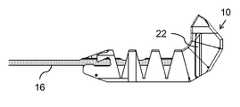
- FIG. 1Ais an isometric view of an implant body for use in an implant, constructed and operative according to the teachings of the present invention, for maintaining a minimum inter-spinous-process spacing;
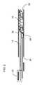
- FIG. 1Bis a partial isometric view of an elongated tightening element for use in an implant, constructed and operative according to the teachings of the present invention, for maintaining a minimum inter-spinous-process spacing;
- FIG. 2is a schematic side cross-sectional view of an implant system, constructed and operative according to the teachings of the present invention, including an implant formed from the implant body of FIG. 1A and the tightening element of FIG. 1B , together with a delivery system;
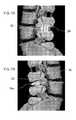
- FIGS. 3A-3Care schematic side views of the implant of FIG. 2 in a straightened state prior to deployment, at an intermediate state during deployment, and in a curved deployed state, respectively;
- FIG. 3Dis an enlarged view of the region of FIG. 3C denoted by circle D showing a locking arrangement of the implant;
- FIGS. 4A-4Care isometric view of the implant of FIG. 2 in states corresponding to FIGS. 3A-3C , respectively;
- FIG. 5is a side isometric view illustrating the implant of FIG. 2 in its curved deployed state after severing of an excess length of said tightening element;
- FIG. 6is schematic superior view illustrating the position of the deployed implant relative to the inferior vertebra
- FIGS. 7A and 7Bare schematic left and right lateral views, respectively, showing the position of the deployed implant relative to the vertebrae;
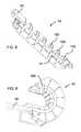
- FIG. 8is a schematic isometric cut-away view of an implant body according to a variant implementation of the present invention.
- FIG. 9is a schematic isometric cut-away view of the implant body of FIG. 8 together with a corresponding tightening element together forming an implant shown in its curved deployed state;
- FIG. 10is an anterior view of the implant of FIG. 9 in its curved deployed state.
- the present inventionis an implant, a system for implantation, and a corresponding method, for maintaining a minimum inter-spinous-process spacing.
- FIGS. 1A-7Bshow various parts of an implant, a corresponding delivery system, and the corresponding manner of deployment of the implant, constructed and operative according to the teachings of the present invention, for maintaining a given minimum inter-spinous-process spacing between adjacent spinous processes of a human or animal subject.
- the implantis formed from an implant body 10 including a plurality of segments 12 hingedly interconnected so as to assume a straightened state ( FIGS. 2 , 3 A and 4 A) for delivery along a conduit and a curved deployed state ( FIGS. 3C , 4 C and 5 ).
- a channel 14passes from a distal segment 12 a along a majority of a length of implant body 12 .
- An elongated tightening element 16is anchored at distal segment 12 a and extends along channel 14 , as best seen in FIG. 2 .
- Implant body 10 and tightening element 16are configured such that tension applied to the tightening element tends to bias the implant body from the straightened state to the curved deployed state.
- implant body 10 and tightening element 16are configured to provide a locking arrangement such that, when tightening element 16 is withdrawn relative to implant body 10 so as to deflect implant body 10 to its curved deployed state, the locking arrangement is effective to lock tightening element 16 relative to implant body 10 , thereby retaining the implant in the curved deployed state.
- One preferred implementation of the locking mechanismis best seen in FIG. 3D where implant body 10 is formed with at least one resilient tooth 18 , and tightening element 16 is formed with at least one corresponding step 20 . Resilient tooth 18 and corresponding step 20 are positioned so as to engage each other in the curved deployed configuration, thereby providing the required locking function.
- a distal portion of the implant body(e.g., segments 12 a - 12 c ) is formed with a set of lateral projections 22 a , 22 b , 22 c configured for inhibiting withdrawal of the distal portion between adjacent spinous processes after deployment.
- the present invention and its various preferred featuresprovide particular advantages over conventional inter-spinous-process spacers.
- the transition of the implant body from the straightened state to the curved deployed stateallows correct latero-lateral deployment of the implant using a unilateral minimally invasive dorsal approach and without requiring traumatic manipulation using gripping tools at the insertion site itself.
- the use of lateral projections to form a retention configuration for the distal portion of the insertprovides a particularly simple structure for achieving effective retention after unilateral insertion of the implant.
- distalis used to refer to the leading portion deployed first from the delivery system while “proximal” is used to refer to the portion deployed last.
- Medialrefers to the intermediate portion.
- the term “medial portion”typically refers to the portion which lies between the spinous processes when deployed, thereby providing the desired spacer effect.
- the dimension of the implant presented between the spinous processesis termed the “width” of the implant, and corresponds to the dimension perpendicular to the plane of curvature.
- the dimension of the segments radially relative to the center of curvatureis termed “height”, and the dimension along the path of insertion is termed “length”.
- the direction of insertionis termed “forward” and the reverse direction is termed “rearward”.
- lateralrefers to a direction from side-to-side in the body, i.e., lying roughly in a coronal plane.
- a “dorsal” approachrefers to an approach for minimally invasive surgical access to the spinal region in which a stab incision is made adjacent to the spinous processes and a delivery conduit is inserted roughly perpendicular (e.g., within about 15 degrees of perpendicular) to a coronal plane.
- a “unilateral” approachrefers to a procedure in which an incision is made only on one side of the spinal column.
- the implant of the present inventionis referred to as being “progressively deflected” as it is deployed from the delivery system.
- the resulting partially deflected statesare illustrated in FIGS. 3B and 4B , with the conduit removed.
- the curved deployed state of implant body 10is preferably a substantially fully deflected state, i.e., where the hinged interconnection between each pair of adjacent segments 12 has flexed to its limit of motion in one direction as defined by additional contact surfaces between the segments.
- implant body 10may be implemented from a wide range of biocompatible materials. Examples include, but are not limited to, various biocompatible metals and metal alloys, and various biocompatible polymers.
- implant bodyis made primarily, and typically exclusively, from ultra-high-molecular-weight poly-ethylene (UHMWPE).
- UHMWPEprovides a highly advantageous combination of low-friction, wear-resistance and resilience which is particularly suited to this application.
- tightening element 16is most preferably also formed primarily from UHMWPE.
- PEEKmay be used as the primary or exclusive material for one or both of implant body 10 and tightening element 16 .
- Implant body 10may be implemented with a wide range of cross-sectional shapes.
- the implantis formed with a generally rectangular cross-section.
- Another particular preferred cross-sectional shapeis a more rounded form, possibly approximating to an ellipse.
- the width of the medial portion of implant bodydefines the required minimum spacing between the spinous processes.
- a surgical kit for implementing the present inventionpreferably includes a plurality of implants, or at least a plurality of implant bodies 10 , with differing widths between which the practitioner can choose according to the surgical needs.
- the heights of all the different width implantsare preferably the same so that the same delivery system can be used for each.
- the effective hinges between segments 12may be implemented in a wide range of ways.
- the hinged interconnectionis achieved by integral hinges integrally formed with segments 12 either during an injection or molding process, or through cutting out of slots from an initial block of material.
- the slotsmay be V-shape, parallel sided, or any other suitable form.
- V-shaped slotsare used so that the curved deployed form of the implant has the spaces between the segments essentially closed.
- alternative implementationssuch as where the hinged interconnection is provided by a separate structure (e.g., a “backbone”) to which segments 12 are attached, also fall within the scope of the present invention.
- the backbonemay be of a different material from the segments themselves, chosen according to the intended application. Options for materials for the backbone include, but are not limited to, metallic materials, various plastics and other polymers, and fabrics.
- the curved deployed form of implant body 10is preferably a roughly arcuate form, typically extending around about 180 degrees to form what appears as a substantially “U-shaped” form.
- the term “U-shaped”is used herein to refer generically to any shape which has a medial portion which turns through roughly 180 degrees (i.e., 180 degrees plus or minus 20 degrees) without specifying in detail the shape, geometry or extent of the two side portions. (It is noted parenthetically that the letter “u” itself is asymmetric in many typefaces.)
- Resilient tooth 18is preferably implemented as an integral part of a proximal block of implant body 10 .
- the structure and dimensions of tooth 18are chosen according to the mechanical properties of the materials used to provide sufficient resilience and secure locking.
- the corresponding step 20may be implemented as any suitably positioned step, formed either by an upward projection or a recessed notch, or a combination thereof.
- alternative locking arrangements employing different forms of engagementmay also be used.
- lateral projections 22 a , 22 b and 22 care preferably implemented as a set of lateral projections including projections from at least two, and preferably three, segments 12 of implant body 10 . These projections are spaced apart when implant body 10 is in its straightened state and are juxtaposed when implant 10 is in its curved deployed state such that the projections cooperate to form at least one elongated retention feature, designated collectively as 22 , extending along at least part of the corresponding two or three segments.
- Retention feature 22preferably provides a “barbed ridge”, i.e., that has a directional structure with a steep step presented so as to inhibit withdrawal of the distal portion of implant body 10 between adjacent spinous processes after deployment.
- elongated retention feature 22extends substantially perpendicular to a line joining a proximal and a distal end of implant body 10 , such that it extends in a generally anterior-posterior direction parallel to the length of the spinous processes when deployed.
- the lateral projectionsare preferably provided symmetrically on both sides of the distal segments 12 a - 12 c.
- Implant body 10preferably also features a proximal block 24 having a width greater than that of the medial portion. This provides retention of the implant in use to prevent the proximal portion of implant body 10 from advancing too far, thereby maintaining proper positioning of the implant with the medial portion between the spinous processes, retention feature 22 on one side and proximal block 24 on the other.
- the delivery systemincludes a conduit 26 sized to receive the implant and to maintain the implant body in the straightened state, a pusher 28 deployable at least partially within conduit 26 to advance the implant so as to emerge from a distal opening 30 of the conduit, and a biasing arrangement 32 deployed to urge tightening element 16 rearward.
- the implant bodyis progressively deflected towards the curved deployed state.
- pusher 28may be a simple manual pusher as illustrated, or may include various manual or power-driven advancing mechanisms to move the implant forward in a convenient and controlled manner.
- biasing arrangement 32is shown schematically as a functional block, but may be implemented in various ways using arrangements of one or more springs or other biasing arrangements, all as will be clear to one ordinarily skilled in the art.
- the delivery systemalso includes a cutting mechanism 34 selectively deployable to sever an excess length of tightening element 16 after the locking arrangement has been locked.
- cutting mechanism 34is illustrated as a blade associated with pusher 28 and actuated by rotating the pusher rod.
- block 24 or conduit 26Clearly, alternative implementations, possibly integrated with block 24 or conduit 26 , are well within the capabilities of one ordinarily skilled in the art. The severing of tightening element 16 leaves the deployed implant in a free-standing configuration as illustrated in FIG. 5 .
- the methodbegins by positioning delivery conduit 26 through a minimally invasive incision, typically of roughly 2 cm length, in a dorsal approach to the inter-spinous-process space.
- the conduitis preferably deployed within 20 degrees to the perpendicular to a coronal plane, and most preferably directly perpendicular.
- Implant body 10is then advanced beyond distal opening 30 of delivery conduit 26 so that implant body 10 is progressively deflected to the curved deployed state, thereby following a curved deployment path passing laterally through the inter-spinous-process space. This leads to the deployment position depicted schematically in FIGS. 6 , 7 A and 7 B.
- a suitable tool for penetrating the tissue and/or generating temporary widening of the openingmay be inserted through conduit 26 or otherwise deployed prior to insertion of the implant.
- FIGS. 8-10there is shown a variant implementation of the implant of the present invention.
- This variantis generally similar, but differs from the first implementation in the form of tightening element 16 and the manner in which it engages implant body 10 .
- tightening element 16is integrally formed with a pointed tip portion 16 a which forms the leading tip of the implant itself.
- the implementation of FIGS. 8-10employs an implant body 10 in which the distal segment 12 a itself provides the distal tip of the implant.
- tightening element 16is formed with a retaining block 16 b which lodges within a recess of distal segment 12 a at the beginning of channel 14 .
- FIGS. 8-10the structure and function of the implementation of FIGS. 8-10 is analogous to that of the first implementation described above.
Landscapes
- Health & Medical Sciences (AREA)
- Orthopedic Medicine & Surgery (AREA)
- Life Sciences & Earth Sciences (AREA)
- Neurology (AREA)
- Surgery (AREA)
- Heart & Thoracic Surgery (AREA)
- Engineering & Computer Science (AREA)
- Biomedical Technology (AREA)
- Nuclear Medicine, Radiotherapy & Molecular Imaging (AREA)
- Medical Informatics (AREA)
- Molecular Biology (AREA)
- Animal Behavior & Ethology (AREA)
- General Health & Medical Sciences (AREA)
- Public Health (AREA)
- Veterinary Medicine (AREA)
- Prostheses (AREA)
Abstract
Description
Claims (24)
Priority Applications (1)
| Application Number | Priority Date | Filing Date | Title |
|---|---|---|---|
| US12/669,794US8672977B2 (en) | 2007-08-09 | 2008-08-11 | Device and method for spinous process distraction |
Applications Claiming Priority (3)
| Application Number | Priority Date | Filing Date | Title |
|---|---|---|---|
| US95482507P | 2007-08-09 | 2007-08-09 | |
| PCT/IB2008/053215WO2009019669A1 (en) | 2007-08-09 | 2008-08-11 | Device and method for spinous process distraction |
| US12/669,794US8672977B2 (en) | 2007-08-09 | 2008-08-11 | Device and method for spinous process distraction |
Publications (2)
| Publication Number | Publication Date |
|---|---|
| US20100198263A1 US20100198263A1 (en) | 2010-08-05 |
| US8672977B2true US8672977B2 (en) | 2014-03-18 |
Family
ID=40032720
Family Applications (1)
| Application Number | Title | Priority Date | Filing Date |
|---|---|---|---|
| US12/669,794Active2029-08-06US8672977B2 (en) | 2007-08-09 | 2008-08-11 | Device and method for spinous process distraction |
Country Status (8)
| Country | Link |
|---|---|
| US (1) | US8672977B2 (en) |
| EP (1) | EP2182867B1 (en) |
| CN (1) | CN101790355B (en) |
| AT (1) | ATE527947T1 (en) |
| CA (1) | CA2693206A1 (en) |
| ES (1) | ES2374760T3 (en) |
| IL (1) | IL203332A (en) |
| WO (1) | WO2009019669A1 (en) |
Cited By (48)
| Publication number | Priority date | Publication date | Assignee | Title |
|---|---|---|---|---|
| US20130138214A1 (en)* | 2010-05-27 | 2013-05-30 | Flexmedex, LLC | Support device and method of use |
| US20140379086A1 (en)* | 2011-09-20 | 2014-12-25 | The University Of Toledo | Expandable Inter-Vertebral Cage and Method of Installing Same |
| US9050112B2 (en) | 2011-08-23 | 2015-06-09 | Flexmedex, LLC | Tissue removal device and method |
| US9259329B2 (en) | 2004-09-21 | 2016-02-16 | Stout Medical Group, L.P. | Expandable support device and method of use |
| US9445918B1 (en) | 2012-10-22 | 2016-09-20 | Nuvasive, Inc. | Expandable spinal fusion implants and related instruments and methods |
| US9662225B2 (en) | 2012-03-06 | 2017-05-30 | DePuy Synthes Products, Inc. | Nubbed plate |
| US9687354B2 (en) | 2008-03-26 | 2017-06-27 | DePuy Synthes Products, Inc. | Posterior intervertebral disc inserter and expansion techniques |
| US9713538B2 (en) | 2006-07-31 | 2017-07-25 | DePuy Synthes Products, Inc. | Spinal fusion implant |
| US9724207B2 (en) | 2003-02-14 | 2017-08-08 | DePuy Synthes Products, Inc. | In-situ formed intervertebral fusion device and method |
| US9801725B2 (en) | 2009-12-09 | 2017-10-31 | DePuy Synthes Products, Inc. | Aspirating implants and method of bony regeneration |
| US9936938B2 (en) | 2007-09-28 | 2018-04-10 | DePuy Synthes Products, Inc. | Balloon with shape control for spinal procedures |
| US9956085B2 (en) | 2005-12-23 | 2018-05-01 | DePuy Synthes Products, Inc. | Flexible elongated chain implant and method of supporting body tissue with same |
| US9993349B2 (en) | 2002-06-27 | 2018-06-12 | DePuy Synthes Products, Inc. | Intervertebral disc |
| US10070968B2 (en) | 2010-08-24 | 2018-09-11 | Flexmedex, LLC | Support device and method for use |
| US10182921B2 (en) | 2012-11-09 | 2019-01-22 | DePuy Synthes Products, Inc. | Interbody device with opening to allow packing graft and other biologics |
| US10285820B2 (en) | 2008-11-12 | 2019-05-14 | Stout Medical Group, L.P. | Fixation device and method |
| US10335289B2 (en) | 2010-09-23 | 2019-07-02 | DePuy Synthes Products, Inc. | Stand alone intervertebral fusion device |
| US10369015B2 (en) | 2010-09-23 | 2019-08-06 | DePuy Synthes Products, Inc. | Implant inserter having a laterally-extending dovetail engagement feature |
| US10433974B2 (en) | 2003-06-30 | 2019-10-08 | DePuy Synthes Products, Inc. | Intervertebral implant with conformable endplate |
| US10500062B2 (en) | 2009-12-10 | 2019-12-10 | DePuy Synthes Products, Inc. | Bellows-like expandable interbody fusion cage |
| US10624758B2 (en) | 2009-03-30 | 2020-04-21 | DePuy Synthes Products, Inc. | Zero profile spinal fusion cage |
| US10758289B2 (en) | 2006-05-01 | 2020-09-01 | Stout Medical Group, L.P. | Expandable support device and method of use |
| US10888433B2 (en) | 2016-12-14 | 2021-01-12 | DePuy Synthes Products, Inc. | Intervertebral implant inserter and related methods |
| WO2021005070A2 (en) | 2019-07-08 | 2021-01-14 | Innospina Sarl | Interspinous implant and associated implantation ancillary |
| US10940014B2 (en) | 2008-11-12 | 2021-03-09 | Stout Medical Group, L.P. | Fixation device and method |
| US10940016B2 (en) | 2017-07-05 | 2021-03-09 | Medos International Sarl | Expandable intervertebral fusion cage |
| US10966840B2 (en) | 2010-06-24 | 2021-04-06 | DePuy Synthes Products, Inc. | Enhanced cage insertion assembly |
| US10973652B2 (en) | 2007-06-26 | 2021-04-13 | DePuy Synthes Products, Inc. | Highly lordosed fusion cage |
| US11020237B2 (en) | 2006-12-22 | 2021-06-01 | Medos International Sarl | Composite vertebral spacers and instrument |
| US11273050B2 (en) | 2006-12-07 | 2022-03-15 | DePuy Synthes Products, Inc. | Intervertebral implant |
| US11344424B2 (en) | 2017-06-14 | 2022-05-31 | Medos International Sarl | Expandable intervertebral implant and related methods |
| US11426290B2 (en) | 2015-03-06 | 2022-08-30 | DePuy Synthes Products, Inc. | Expandable intervertebral implant, system, kit and method |
| US11426286B2 (en) | 2020-03-06 | 2022-08-30 | Eit Emerging Implant Technologies Gmbh | Expandable intervertebral implant |
| US11446155B2 (en) | 2017-05-08 | 2022-09-20 | Medos International Sarl | Expandable cage |
| US11446156B2 (en) | 2018-10-25 | 2022-09-20 | Medos International Sarl | Expandable intervertebral implant, inserter instrument, and related methods |
| US11452607B2 (en) | 2010-10-11 | 2022-09-27 | DePuy Synthes Products, Inc. | Expandable interspinous process spacer implant |
| US11497619B2 (en) | 2013-03-07 | 2022-11-15 | DePuy Synthes Products, Inc. | Intervertebral implant |
| US11510788B2 (en) | 2016-06-28 | 2022-11-29 | Eit Emerging Implant Technologies Gmbh | Expandable, angularly adjustable intervertebral cages |
| US11529241B2 (en) | 2010-09-23 | 2022-12-20 | DePuy Synthes Products, Inc. | Fusion cage with in-line single piece fixation |
| US11596523B2 (en) | 2016-06-28 | 2023-03-07 | Eit Emerging Implant Technologies Gmbh | Expandable and angularly adjustable articulating intervertebral cages |
| US11602438B2 (en) | 2008-04-05 | 2023-03-14 | DePuy Synthes Products, Inc. | Expandable intervertebral implant |
| US11654033B2 (en) | 2010-06-29 | 2023-05-23 | DePuy Synthes Products, Inc. | Distractible intervertebral implant |
| US11737881B2 (en) | 2008-01-17 | 2023-08-29 | DePuy Synthes Products, Inc. | Expandable intervertebral implant and associated method of manufacturing the same |
| US11752009B2 (en) | 2021-04-06 | 2023-09-12 | Medos International Sarl | Expandable intervertebral fusion cage |
| US11850160B2 (en) | 2021-03-26 | 2023-12-26 | Medos International Sarl | Expandable lordotic intervertebral fusion cage |
| USRE49973E1 (en) | 2013-02-28 | 2024-05-21 | DePuy Synthes Products, Inc. | Expandable intervertebral implant, system, kit and method |
| US12090064B2 (en) | 2022-03-01 | 2024-09-17 | Medos International Sarl | Stabilization members for expandable intervertebral implants, and related systems and methods |
| US12440346B2 (en) | 2023-03-31 | 2025-10-14 | DePuy Synthes Products, Inc. | Expandable intervertebral implant |
Families Citing this family (35)
| Publication number | Priority date | Publication date | Assignee | Title |
|---|---|---|---|---|
| US8500778B2 (en)* | 2006-02-01 | 2013-08-06 | DePuy Synthes Products, LLC | Interspinous process spacer |
| US8021429B2 (en)* | 2007-03-08 | 2011-09-20 | Zimmer Spine, Inc. | Deployable segmented TLIF device |
| EP2271377A2 (en)* | 2008-03-12 | 2011-01-12 | Nonlinear Technologies Ltd. | Spinal implant with structural support and bone interface surfaces formed from uhmwpe |
| US20110029085A1 (en)* | 2009-07-31 | 2011-02-03 | Warsaw Orthopedic, Inc. | Flexible spinal implant |
| US9028553B2 (en) | 2009-11-05 | 2015-05-12 | DePuy Synthes Products, Inc. | Self-pivoting spinal implant and associated instrumentation |
| JP5774028B2 (en) | 2010-02-16 | 2015-09-02 | エヌエルティー スパイン エルティーディー. | Medical device locking mechanism |
| US9907560B2 (en) | 2010-06-24 | 2018-03-06 | DePuy Synthes Products, Inc. | Flexible vertebral body shavers |
| CN103096843A (en) | 2010-07-21 | 2013-05-08 | Nlt脊椎有限公司 | Spinal surgery implants and delivery system |
| EP2637587A1 (en) | 2010-11-09 | 2013-09-18 | Benvenue Medical, Inc. | Devices and methods for treatment of a bone fracture |
| US8512408B2 (en) | 2010-12-17 | 2013-08-20 | Warsaw Orthopedic, Inc. | Flexiable spinal implant |
| EP3485851B1 (en) | 2011-03-22 | 2021-08-25 | DePuy Synthes Products, LLC | Universal trial for lateral cages |
| US9149306B2 (en) | 2011-06-21 | 2015-10-06 | Seaspine, Inc. | Spinous process device |
| US20140163624A1 (en)* | 2011-08-02 | 2014-06-12 | NLT-Spine Ltd. | Bone Screw with Deflectable Portion |
| WO2013064997A1 (en) | 2011-10-31 | 2013-05-10 | NLT-Spine Ltd. | Bony structure fixation clamp |
| US9198765B1 (en) | 2011-10-31 | 2015-12-01 | Nuvasive, Inc. | Expandable spinal fusion implants and related methods |
| US9060870B2 (en) | 2012-02-05 | 2015-06-23 | Michael J. Milella, Jr. | In-situ formed spinal implant |
| US9226764B2 (en) | 2012-03-06 | 2016-01-05 | DePuy Synthes Products, Inc. | Conformable soft tissue removal instruments |
| US10022245B2 (en) | 2012-12-17 | 2018-07-17 | DePuy Synthes Products, Inc. | Polyaxial articulating instrument |
| US9358120B2 (en) | 2013-03-14 | 2016-06-07 | DePuy Synthes Products, Inc. | Expandable coil spinal implant |
| US9572676B2 (en) | 2013-03-14 | 2017-02-21 | DePuy Synthes Products, Inc. | Adjustable multi-volume balloon for spinal interventions |
| US9480574B2 (en) | 2013-03-14 | 2016-11-01 | Benvenue Medical, Inc. | Spinal fusion implants and devices and methods for deploying such implants |
| US9585761B2 (en) | 2013-03-14 | 2017-03-07 | DePuy Synthes Products, Inc. | Angulated rings and bonded foils for use with balloons for fusion and dynamic stabilization |
| US9795493B1 (en) | 2013-03-15 | 2017-10-24 | Nuvasive, Inc. | Expandable intervertebral implant and methods of use thereof |
| CN104644291B (en)* | 2013-11-18 | 2017-12-12 | 宝楠生技股份有限公司 | memory type intervertebral fusion fixation device |
| US10314605B2 (en) | 2014-07-08 | 2019-06-11 | Benvenue Medical, Inc. | Apparatus and methods for disrupting intervertebral disc tissue |
| US10022243B2 (en) | 2015-02-06 | 2018-07-17 | Benvenue Medical, Inc. | Graft material injector system and method |
| US10758286B2 (en) | 2017-03-22 | 2020-09-01 | Benvenue Medical, Inc. | Minimal impact access system to disc space |
| US10966843B2 (en) | 2017-07-18 | 2021-04-06 | DePuy Synthes Products, Inc. | Implant inserters and related methods |
| US11045331B2 (en) | 2017-08-14 | 2021-06-29 | DePuy Synthes Products, Inc. | Intervertebral implant inserters and related methods |
| US10575962B2 (en)* | 2017-11-20 | 2020-03-03 | Warsaw Orthopedic, Inc. | Spinal implant |
| WO2019148083A1 (en) | 2018-01-29 | 2019-08-01 | Benvenue Medical, Inc. | Minimally invasive interbody fusion |
| WO2019178575A1 (en) | 2018-03-16 | 2019-09-19 | Benvenue Medical, Inc. | Articulated instrumentation and methods of using the same |
| US10736756B2 (en) | 2018-03-30 | 2020-08-11 | Warsaw Orthopedic, Inc. | Radiolucent trial |
| US10537447B2 (en) | 2018-03-30 | 2020-01-21 | Warsaw Orthopedic, Inc. | Radiolucent trial |
| US11166825B1 (en) | 2020-07-01 | 2021-11-09 | Warsaw Orthopedic, Inc. | Spinal implant |
Citations (25)
| Publication number | Priority date | Publication date | Assignee | Title |
|---|---|---|---|---|
| US6387130B1 (en)* | 1999-04-16 | 2002-05-14 | Nuvasive, Inc. | Segmented linked intervertebral implant systems |
| US6402750B1 (en)* | 2000-04-04 | 2002-06-11 | Spinlabs, Llc | Devices and methods for the treatment of spinal disorders |
| US6461359B1 (en)* | 1999-11-10 | 2002-10-08 | Clifford Tribus | Spine stabilization device |
| US20030187445A1 (en)* | 2000-04-04 | 2003-10-02 | Peter T. Keith | Devices and methods for annular repair of intervertebral discs |
| US20050261683A1 (en)* | 2001-07-02 | 2005-11-24 | Veldhuizen Albert G | Collapsible and expandable instrument for insertion in a dorsal vertebra |
| US20060036273A1 (en)* | 2004-08-11 | 2006-02-16 | Tzony Siegal | Spinal surgery system and method |
| US20060142858A1 (en)* | 2004-12-16 | 2006-06-29 | Dennis Colleran | Expandable implants for spinal disc replacement |
| US20060189999A1 (en)* | 2005-02-24 | 2006-08-24 | Paul Zwirkoski | Linked slideable and interlockable rotatable components |
| US20060265077A1 (en)* | 2005-02-23 | 2006-11-23 | Zwirkoski Paul A | Spinal repair |
| US20070067035A1 (en)* | 2005-09-16 | 2007-03-22 | Falahee Mark H | Steerable interbody fusion cage |
| US20070260314A1 (en)* | 2006-05-02 | 2007-11-08 | Ashok Biyani | Transforaminal lumbar interbody fusion cage |
| US20080125865A1 (en)* | 2006-09-21 | 2008-05-29 | Abdelgany Mahmoud F | Articulating interbody spacer, vertebral body replacement |
| US20080133012A1 (en)* | 2006-11-16 | 2008-06-05 | Mcguckin James F | Spinal implant and method of use |
| US20080221687A1 (en)* | 2007-03-08 | 2008-09-11 | Zimmer Spine, Inc. | Deployable segmented tlif device |
| US20080249628A1 (en)* | 2007-04-09 | 2008-10-09 | Moti Altarac | Multi-component interbody device |
| US20080312743A1 (en)* | 2007-06-15 | 2008-12-18 | Thierry Vila | Nucleus Prostheses |
| US20090005871A1 (en)* | 2007-04-10 | 2009-01-01 | David White | Suture-based orthopedic joint devices |
| US20090240335A1 (en)* | 2008-03-24 | 2009-09-24 | Arcenio Gregory B | Expandable Devices for Emplacement in Body Parts and Methods Associated Therewith |
| US20090254185A1 (en)* | 2004-12-16 | 2009-10-08 | Doellinger Horst | Implant for the treatment of lumbar spinal canal stenosis |
| US20090292323A1 (en)* | 2008-05-20 | 2009-11-26 | Chirico Paul E | Systems, devices and methods for posterior lumbar interbody fusion |
| US7959652B2 (en) | 2005-04-18 | 2011-06-14 | Kyphon Sarl | Interspinous process implant having deployable wings and method of implantation |
| US8034110B2 (en)* | 2006-07-31 | 2011-10-11 | Depuy Spine, Inc. | Spinal fusion implant |
| US8105365B2 (en)* | 2000-02-16 | 2012-01-31 | Trans1 Inc. | Methods and apparatus for performing therapeutic procedures in the spine |
| US20120071980A1 (en)* | 2010-09-16 | 2012-03-22 | Alphatec Spine, Inc. | Steerable spine implant and system |
| US8349013B2 (en) | 1997-01-02 | 2013-01-08 | Kyphon Sarl | Spine distraction implant |
Family Cites Families (2)
| Publication number | Priority date | Publication date | Assignee | Title |
|---|---|---|---|---|
| DE19710392C1 (en)* | 1997-03-13 | 1999-07-01 | Haehnel Michael | Slipped disc implant comprises an extensible, hinged or wound body |
| EP1833375B1 (en)* | 2005-01-05 | 2013-07-17 | NLT Spine Ltd. | Straight introduction device that assumes curved configuration |
- 2008
- 2008-08-11WOPCT/IB2008/053215patent/WO2009019669A1/enactiveApplication Filing
- 2008-08-11CNCN2008801026266Apatent/CN101790355B/ennot_activeExpired - Fee Related
- 2008-08-11CACA2693206Apatent/CA2693206A1/ennot_activeAbandoned
- 2008-08-11USUS12/669,794patent/US8672977B2/enactiveActive
- 2008-08-11ATAT08789594Tpatent/ATE527947T1/ennot_activeIP Right Cessation
- 2008-08-11ESES08789594Tpatent/ES2374760T3/enactiveActive
- 2008-08-11EPEP08789594Apatent/EP2182867B1/ennot_activeNot-in-force
- 2010
- 2010-01-14ILIL203332Apatent/IL203332A/ennot_activeIP Right Cessation
Patent Citations (29)
| Publication number | Priority date | Publication date | Assignee | Title |
|---|---|---|---|---|
| US8349013B2 (en) | 1997-01-02 | 2013-01-08 | Kyphon Sarl | Spine distraction implant |
| US6387130B1 (en)* | 1999-04-16 | 2002-05-14 | Nuvasive, Inc. | Segmented linked intervertebral implant systems |
| US6461359B1 (en)* | 1999-11-10 | 2002-10-08 | Clifford Tribus | Spine stabilization device |
| US8105365B2 (en)* | 2000-02-16 | 2012-01-31 | Trans1 Inc. | Methods and apparatus for performing therapeutic procedures in the spine |
| US20030187445A1 (en)* | 2000-04-04 | 2003-10-02 | Peter T. Keith | Devices and methods for annular repair of intervertebral discs |
| US6402750B1 (en)* | 2000-04-04 | 2002-06-11 | Spinlabs, Llc | Devices and methods for the treatment of spinal disorders |
| US20050261683A1 (en)* | 2001-07-02 | 2005-11-24 | Veldhuizen Albert G | Collapsible and expandable instrument for insertion in a dorsal vertebra |
| US20060036273A1 (en)* | 2004-08-11 | 2006-02-16 | Tzony Siegal | Spinal surgery system and method |
| US20080208255A1 (en)* | 2004-08-11 | 2008-08-28 | Tzony Siegal | Devices For Introduction Into A Body Via A Substantially Straight Conduit To Form A Predefined Curved Configuration, And Methods Employing Same |
| US20060142858A1 (en)* | 2004-12-16 | 2006-06-29 | Dennis Colleran | Expandable implants for spinal disc replacement |
| US20090254185A1 (en)* | 2004-12-16 | 2009-10-08 | Doellinger Horst | Implant for the treatment of lumbar spinal canal stenosis |
| US20060265077A1 (en)* | 2005-02-23 | 2006-11-23 | Zwirkoski Paul A | Spinal repair |
| US20060189999A1 (en)* | 2005-02-24 | 2006-08-24 | Paul Zwirkoski | Linked slideable and interlockable rotatable components |
| US7959652B2 (en) | 2005-04-18 | 2011-06-14 | Kyphon Sarl | Interspinous process implant having deployable wings and method of implantation |
| US20070067035A1 (en)* | 2005-09-16 | 2007-03-22 | Falahee Mark H | Steerable interbody fusion cage |
| US20070260314A1 (en)* | 2006-05-02 | 2007-11-08 | Ashok Biyani | Transforaminal lumbar interbody fusion cage |
| US8034110B2 (en)* | 2006-07-31 | 2011-10-11 | Depuy Spine, Inc. | Spinal fusion implant |
| US20080125865A1 (en)* | 2006-09-21 | 2008-05-29 | Abdelgany Mahmoud F | Articulating interbody spacer, vertebral body replacement |
| US8025697B2 (en)* | 2006-09-21 | 2011-09-27 | Custom Spine, Inc. | Articulating interbody spacer, vertebral body replacement |
| US20080133012A1 (en)* | 2006-11-16 | 2008-06-05 | Mcguckin James F | Spinal implant and method of use |
| US20080221687A1 (en)* | 2007-03-08 | 2008-09-11 | Zimmer Spine, Inc. | Deployable segmented tlif device |
| US20120004731A1 (en)* | 2007-03-08 | 2012-01-05 | Zimmer Spine, Inc. | Deployable segmented tlif device |
| US8021429B2 (en)* | 2007-03-08 | 2011-09-20 | Zimmer Spine, Inc. | Deployable segmented TLIF device |
| US20080249628A1 (en)* | 2007-04-09 | 2008-10-09 | Moti Altarac | Multi-component interbody device |
| US20090005871A1 (en)* | 2007-04-10 | 2009-01-01 | David White | Suture-based orthopedic joint devices |
| US20080312743A1 (en)* | 2007-06-15 | 2008-12-18 | Thierry Vila | Nucleus Prostheses |
| US20090240335A1 (en)* | 2008-03-24 | 2009-09-24 | Arcenio Gregory B | Expandable Devices for Emplacement in Body Parts and Methods Associated Therewith |
| US20090292323A1 (en)* | 2008-05-20 | 2009-11-26 | Chirico Paul E | Systems, devices and methods for posterior lumbar interbody fusion |
| US20120071980A1 (en)* | 2010-09-16 | 2012-03-22 | Alphatec Spine, Inc. | Steerable spine implant and system |
Cited By (133)
| Publication number | Priority date | Publication date | Assignee | Title |
|---|---|---|---|---|
| US9993349B2 (en) | 2002-06-27 | 2018-06-12 | DePuy Synthes Products, Inc. | Intervertebral disc |
| US10238500B2 (en) | 2002-06-27 | 2019-03-26 | DePuy Synthes Products, Inc. | Intervertebral disc |
| US9925060B2 (en) | 2003-02-14 | 2018-03-27 | DePuy Synthes Products, Inc. | In-situ formed intervertebral fusion device and method |
| US11207187B2 (en) | 2003-02-14 | 2021-12-28 | DePuy Synthes Products, Inc. | In-situ formed intervertebral fusion device and method |
| US10555817B2 (en) | 2003-02-14 | 2020-02-11 | DePuy Synthes Products, Inc. | In-situ formed intervertebral fusion device and method |
| US10492918B2 (en) | 2003-02-14 | 2019-12-03 | DePuy Synthes Products, Inc. | In-situ formed intervertebral fusion device and method |
| US10085843B2 (en) | 2003-02-14 | 2018-10-02 | DePuy Synthes Products, Inc. | In-situ formed intervertebral fusion device and method |
| US10376372B2 (en) | 2003-02-14 | 2019-08-13 | DePuy Synthes Products, Inc. | In-situ formed intervertebral fusion device and method |
| US10433971B2 (en) | 2003-02-14 | 2019-10-08 | DePuy Synthes Products, Inc. | In-situ formed intervertebral fusion device and method |
| US11432938B2 (en) | 2003-02-14 | 2022-09-06 | DePuy Synthes Products, Inc. | In-situ intervertebral fusion device and method |
| US10420651B2 (en) | 2003-02-14 | 2019-09-24 | DePuy Synthes Products, Inc. | In-situ formed intervertebral fusion device and method |
| US9724207B2 (en) | 2003-02-14 | 2017-08-08 | DePuy Synthes Products, Inc. | In-situ formed intervertebral fusion device and method |
| US9730803B2 (en) | 2003-02-14 | 2017-08-15 | DePuy Synthes Products, Inc. | Method of in-situ formation of an intervertebral fusion device |
| US9801729B2 (en) | 2003-02-14 | 2017-10-31 | DePuy Synthes Products, Inc. | In-situ formed intervertebral fusion device and method |
| US10583013B2 (en) | 2003-02-14 | 2020-03-10 | DePuy Synthes Products, Inc. | In-situ formed intervertebral fusion device and method |
| US9788963B2 (en) | 2003-02-14 | 2017-10-17 | DePuy Synthes Products, Inc. | In-situ formed intervertebral fusion device and method |
| US10405986B2 (en) | 2003-02-14 | 2019-09-10 | DePuy Synthes Products, Inc. | In-situ formed intervertebral fusion device and method |
| US9808351B2 (en) | 2003-02-14 | 2017-11-07 | DePuy Synthes Products, Inc. | In-situ formed intervertebral fusion device and method |
| US9814590B2 (en) | 2003-02-14 | 2017-11-14 | DePuy Synthes Products, Inc. | In-situ formed intervertebral fusion device and method |
| US9814589B2 (en) | 2003-02-14 | 2017-11-14 | DePuy Synthes Products, Inc. | In-situ formed intervertebral fusion device and method |
| US10639164B2 (en) | 2003-02-14 | 2020-05-05 | DePuy Synthes Products, Inc. | In-situ formed intervertebral fusion device and method |
| US11096794B2 (en) | 2003-02-14 | 2021-08-24 | DePuy Synthes Products, Inc. | In-situ formed intervertebral fusion device and method |
| US10786361B2 (en) | 2003-02-14 | 2020-09-29 | DePuy Synthes Products, Inc. | In-situ formed intervertebral fusion device and method |
| US10575959B2 (en) | 2003-02-14 | 2020-03-03 | DePuy Synthes Products, Inc. | In-situ formed intervertebral fusion device and method |
| US11612493B2 (en) | 2003-06-30 | 2023-03-28 | DePuy Synthes Products, Inc. | Intervertebral implant with conformable endplate |
| US10433974B2 (en) | 2003-06-30 | 2019-10-08 | DePuy Synthes Products, Inc. | Intervertebral implant with conformable endplate |
| US9259329B2 (en) | 2004-09-21 | 2016-02-16 | Stout Medical Group, L.P. | Expandable support device and method of use |
| US11051954B2 (en) | 2004-09-21 | 2021-07-06 | Stout Medical Group, L.P. | Expandable support device and method of use |
| US9314349B2 (en) | 2004-09-21 | 2016-04-19 | Stout Medical Group, L.P. | Expandable support device and method of use |
| US10881520B2 (en) | 2005-12-23 | 2021-01-05 | DePuy Synthes Products, Inc. | Flexible elongated chain implant and method of supporting body tissue with same |
| US9956085B2 (en) | 2005-12-23 | 2018-05-01 | DePuy Synthes Products, Inc. | Flexible elongated chain implant and method of supporting body tissue with same |
| US11701233B2 (en) | 2005-12-23 | 2023-07-18 | DePuy Synthes Products, Inc. | Flexible elongated chain implant and method of supporting body tissue with same |
| US11406508B2 (en) | 2005-12-23 | 2022-08-09 | DePuy Synthes Products, Inc. | Flexible elongated chain implant and method of supporting body tissue with same |
| US10813677B2 (en) | 2006-05-01 | 2020-10-27 | Stout Medical Group, L.P. | Expandable support device and method of use |
| US10758289B2 (en) | 2006-05-01 | 2020-09-01 | Stout Medical Group, L.P. | Expandable support device and method of use |
| US11141208B2 (en) | 2006-05-01 | 2021-10-12 | Stout Medical Group, L.P. | Expandable support device and method of use |
| US9737413B2 (en) | 2006-07-31 | 2017-08-22 | DePuy Synthes Products, Inc. | Spinal fusion implant |
| US10695191B2 (en) | 2006-07-31 | 2020-06-30 | DePuy Synthes Products, Inc. | Spinal fusion implant |
| US9713538B2 (en) | 2006-07-31 | 2017-07-25 | DePuy Synthes Products, Inc. | Spinal fusion implant |
| US10010428B2 (en) | 2006-07-31 | 2018-07-03 | DePuy Synthes Products, Inc. | Spinal fusion implant |
| US11432942B2 (en) | 2006-12-07 | 2022-09-06 | DePuy Synthes Products, Inc. | Intervertebral implant |
| US11273050B2 (en) | 2006-12-07 | 2022-03-15 | DePuy Synthes Products, Inc. | Intervertebral implant |
| US11497618B2 (en) | 2006-12-07 | 2022-11-15 | DePuy Synthes Products, Inc. | Intervertebral implant |
| US11642229B2 (en) | 2006-12-07 | 2023-05-09 | DePuy Synthes Products, Inc. | Intervertebral implant |
| US11660206B2 (en) | 2006-12-07 | 2023-05-30 | DePuy Synthes Products, Inc. | Intervertebral implant |
| US11712345B2 (en) | 2006-12-07 | 2023-08-01 | DePuy Synthes Products, Inc. | Intervertebral implant |
| US11020237B2 (en) | 2006-12-22 | 2021-06-01 | Medos International Sarl | Composite vertebral spacers and instrument |
| US11622868B2 (en) | 2007-06-26 | 2023-04-11 | DePuy Synthes Products, Inc. | Highly lordosed fusion cage |
| US10973652B2 (en) | 2007-06-26 | 2021-04-13 | DePuy Synthes Products, Inc. | Highly lordosed fusion cage |
| US12426868B2 (en) | 2007-09-28 | 2025-09-30 | DePuy Synthes Products, Inc. | Balloon with shape control for spinal procedures |
| US9936938B2 (en) | 2007-09-28 | 2018-04-10 | DePuy Synthes Products, Inc. | Balloon with shape control for spinal procedures |
| US10786231B2 (en) | 2007-09-28 | 2020-09-29 | DePuy Synthes Products, Inc. | Balloon with shape control for spinal procedures |
| US11737881B2 (en) | 2008-01-17 | 2023-08-29 | DePuy Synthes Products, Inc. | Expandable intervertebral implant and associated method of manufacturing the same |
| US9687354B2 (en) | 2008-03-26 | 2017-06-27 | DePuy Synthes Products, Inc. | Posterior intervertebral disc inserter and expansion techniques |
| US10206784B2 (en) | 2008-03-26 | 2019-02-19 | DePuy Synthes Products, Inc. | Posterior intervertebral disc inserter and expansion techniques |
| US11712342B2 (en) | 2008-04-05 | 2023-08-01 | DePuy Synthes Products, Inc. | Expandable intervertebral implant |
| US12023255B2 (en) | 2008-04-05 | 2024-07-02 | DePuy Synthes Products, Inc. | Expandable inter vertebral implant |
| US11617655B2 (en) | 2008-04-05 | 2023-04-04 | DePuy Synthes Products, Inc. | Expandable intervertebral implant |
| US11701234B2 (en) | 2008-04-05 | 2023-07-18 | DePuy Synthes Products, Inc. | Expandable intervertebral implant |
| US11712341B2 (en) | 2008-04-05 | 2023-08-01 | DePuy Synthes Products, Inc. | Expandable intervertebral implant |
| US11707359B2 (en) | 2008-04-05 | 2023-07-25 | DePuy Synthes Products, Inc. | Expandable intervertebral implant |
| US12011361B2 (en) | 2008-04-05 | 2024-06-18 | DePuy Synthes Products, Inc. | Expandable intervertebral implant |
| US11602438B2 (en) | 2008-04-05 | 2023-03-14 | DePuy Synthes Products, Inc. | Expandable intervertebral implant |
| US10285820B2 (en) | 2008-11-12 | 2019-05-14 | Stout Medical Group, L.P. | Fixation device and method |
| US10285819B2 (en) | 2008-11-12 | 2019-05-14 | Stout Medical Group, L.P. | Fixation device and method |
| US10292828B2 (en) | 2008-11-12 | 2019-05-21 | Stout Medical Group, L.P. | Fixation device and method |
| US10940014B2 (en) | 2008-11-12 | 2021-03-09 | Stout Medical Group, L.P. | Fixation device and method |
| US10624758B2 (en) | 2009-03-30 | 2020-04-21 | DePuy Synthes Products, Inc. | Zero profile spinal fusion cage |
| US11612491B2 (en) | 2009-03-30 | 2023-03-28 | DePuy Synthes Products, Inc. | Zero profile spinal fusion cage |
| US12097124B2 (en) | 2009-03-30 | 2024-09-24 | DePuy Synthes Products, Inc. | Zero profile spinal fusion cage |
| US10342662B2 (en) | 2009-12-09 | 2019-07-09 | DePuy Synthes Products, Inc. | Aspirating implants and method of bony regeneration |
| US9801725B2 (en) | 2009-12-09 | 2017-10-31 | DePuy Synthes Products, Inc. | Aspirating implants and method of bony regeneration |
| US10500062B2 (en) | 2009-12-10 | 2019-12-10 | DePuy Synthes Products, Inc. | Bellows-like expandable interbody fusion cage |
| US11607321B2 (en) | 2009-12-10 | 2023-03-21 | DePuy Synthes Products, Inc. | Bellows-like expandable interbody fusion cage |
| US20130138214A1 (en)* | 2010-05-27 | 2013-05-30 | Flexmedex, LLC | Support device and method of use |
| US10966840B2 (en) | 2010-06-24 | 2021-04-06 | DePuy Synthes Products, Inc. | Enhanced cage insertion assembly |
| US11872139B2 (en) | 2010-06-24 | 2024-01-16 | DePuy Synthes Products, Inc. | Enhanced cage insertion assembly |
| US11654033B2 (en) | 2010-06-29 | 2023-05-23 | DePuy Synthes Products, Inc. | Distractible intervertebral implant |
| US10070968B2 (en) | 2010-08-24 | 2018-09-11 | Flexmedex, LLC | Support device and method for use |
| US11529241B2 (en) | 2010-09-23 | 2022-12-20 | DePuy Synthes Products, Inc. | Fusion cage with in-line single piece fixation |
| US11382768B2 (en) | 2010-09-23 | 2022-07-12 | DePuy Synthes Products, Inc. | Implant inserter having a laterally-extending dovetail engagement feature |
| US10369015B2 (en) | 2010-09-23 | 2019-08-06 | DePuy Synthes Products, Inc. | Implant inserter having a laterally-extending dovetail engagement feature |
| US12109127B2 (en) | 2010-09-23 | 2024-10-08 | DePuy Synthes Products, Inc. | Implant inserter having a laterally-extending dovetail engagement feature |
| US10335289B2 (en) | 2010-09-23 | 2019-07-02 | DePuy Synthes Products, Inc. | Stand alone intervertebral fusion device |
| US11678996B2 (en) | 2010-09-23 | 2023-06-20 | DePuy Synthes Products, Inc. | Stand alone intervertebral fusion device |
| US11452607B2 (en) | 2010-10-11 | 2022-09-27 | DePuy Synthes Products, Inc. | Expandable interspinous process spacer implant |
| US9050112B2 (en) | 2011-08-23 | 2015-06-09 | Flexmedex, LLC | Tissue removal device and method |
| US9561115B2 (en)* | 2011-09-20 | 2017-02-07 | The University Of Toledo | Expandable inter-vertebral cage and method of installing same |
| US20140379086A1 (en)* | 2011-09-20 | 2014-12-25 | The University Of Toledo | Expandable Inter-Vertebral Cage and Method of Installing Same |
| US9872781B2 (en) | 2012-03-06 | 2018-01-23 | DePuy Synthes Products, Inc. | Nubbed plate |
| US9668877B2 (en) | 2012-03-06 | 2017-06-06 | DePuy Synthes Products, Inc. | Nubbed plate |
| US11844702B2 (en) | 2012-03-06 | 2023-12-19 | DePuy Synthes Products, Inc. | Nubbed plate |
| US10327915B2 (en) | 2012-03-06 | 2019-06-25 | DePuy Synthes Products, Inc. | Nubbed plate |
| US11071634B2 (en) | 2012-03-06 | 2021-07-27 | DePuy Synthes Products, Inc. | Nubbed plate |
| US9662225B2 (en) | 2012-03-06 | 2017-05-30 | DePuy Synthes Products, Inc. | Nubbed plate |
| US11399954B2 (en) | 2012-10-22 | 2022-08-02 | Nuvasive, Inc. | Expandable spinal fusion implant, related instruments and methods |
| US12048635B2 (en) | 2012-10-22 | 2024-07-30 | Nuvasive, Inc. | Expandable spinal fusion implant, related instruments and methods |
| US10350084B1 (en) | 2012-10-22 | 2019-07-16 | Nuvasive, Inc. | Expandable spinal fusion implant, related instruments and methods |
| US9445918B1 (en) | 2012-10-22 | 2016-09-20 | Nuvasive, Inc. | Expandable spinal fusion implants and related instruments and methods |
| US11497616B2 (en) | 2012-11-09 | 2022-11-15 | DePuy Synthes Products, Inc. | Interbody device with opening to allow packing graft and other biologics |
| US10182921B2 (en) | 2012-11-09 | 2019-01-22 | DePuy Synthes Products, Inc. | Interbody device with opening to allow packing graft and other biologics |
| USRE49973E1 (en) | 2013-02-28 | 2024-05-21 | DePuy Synthes Products, Inc. | Expandable intervertebral implant, system, kit and method |
| US11497619B2 (en) | 2013-03-07 | 2022-11-15 | DePuy Synthes Products, Inc. | Intervertebral implant |
| US11850164B2 (en) | 2013-03-07 | 2023-12-26 | DePuy Synthes Products, Inc. | Intervertebral implant |
| US11426290B2 (en) | 2015-03-06 | 2022-08-30 | DePuy Synthes Products, Inc. | Expandable intervertebral implant, system, kit and method |
| US11510788B2 (en) | 2016-06-28 | 2022-11-29 | Eit Emerging Implant Technologies Gmbh | Expandable, angularly adjustable intervertebral cages |
| US11596522B2 (en) | 2016-06-28 | 2023-03-07 | Eit Emerging Implant Technologies Gmbh | Expandable and angularly adjustable intervertebral cages with articulating joint |
| US11596523B2 (en) | 2016-06-28 | 2023-03-07 | Eit Emerging Implant Technologies Gmbh | Expandable and angularly adjustable articulating intervertebral cages |
| US12390343B2 (en) | 2016-06-28 | 2025-08-19 | Eit Emerging Implant Technologies Gmbh | Expandable, angularly adjustable intervertebral cages |
| US12433757B2 (en) | 2016-06-28 | 2025-10-07 | Eit Emerging Implant Technologies Gmbh | Expandable, angularly adjustable and articulating intervertebral cages |
| US10888433B2 (en) | 2016-12-14 | 2021-01-12 | DePuy Synthes Products, Inc. | Intervertebral implant inserter and related methods |
| US12427031B2 (en) | 2017-05-08 | 2025-09-30 | Medos International Sarl | Expandable cage |
| US11446155B2 (en) | 2017-05-08 | 2022-09-20 | Medos International Sarl | Expandable cage |
| US11344424B2 (en) | 2017-06-14 | 2022-05-31 | Medos International Sarl | Expandable intervertebral implant and related methods |
| US10940016B2 (en) | 2017-07-05 | 2021-03-09 | Medos International Sarl | Expandable intervertebral fusion cage |
| US11446156B2 (en) | 2018-10-25 | 2022-09-20 | Medos International Sarl | Expandable intervertebral implant, inserter instrument, and related methods |
| KR20220034154A (en)* | 2019-07-08 | 2022-03-17 | 이노스피나 에스에이알엘 | Spinal Intervertebral Vertebral Implants and Related Graft Appendages |
| CN114126546A (en)* | 2019-07-08 | 2022-03-01 | 伊诺斯皮纳有限责任公司 | Interspinous vertebral implant and associated implantation aid |
| IL289288B1 (en)* | 2019-07-08 | 2025-09-01 | Innospina Sarl | Interspinous vertebral implant and associated implantation ancillary |
| WO2021005070A3 (en)* | 2019-07-08 | 2021-04-15 | Innospina Sarl | Interspinous implant and associated implantation ancillary |
| US20220249243A1 (en)* | 2019-07-08 | 2022-08-11 | Innospina Sarl | Interspinous implant and associated implantation ancillary |
| US12318302B2 (en)* | 2019-07-08 | 2025-06-03 | Innospina Sarl | Interspinous implant and associated implantation ancillary |
| FR3098385A1 (en)* | 2019-07-08 | 2021-01-15 | Innospina Sarl | Interspinous vertebral implant and associated ancillary placement |
| WO2021005070A2 (en) | 2019-07-08 | 2021-01-14 | Innospina Sarl | Interspinous implant and associated implantation ancillary |
| CN114126546B (en)* | 2019-07-08 | 2025-02-25 | 伊诺斯皮纳有限责任公司 | Interspinous vertebral implants and associated implant assisting devices |
| KR102790780B1 (en) | 2019-07-08 | 2025-04-02 | 이노스피나 에스에이알엘 | Interspinous vertebrae grafts and associated graft accessories |
| US11426286B2 (en) | 2020-03-06 | 2022-08-30 | Eit Emerging Implant Technologies Gmbh | Expandable intervertebral implant |
| US11806245B2 (en) | 2020-03-06 | 2023-11-07 | Eit Emerging Implant Technologies Gmbh | Expandable intervertebral implant |
| US11850160B2 (en) | 2021-03-26 | 2023-12-26 | Medos International Sarl | Expandable lordotic intervertebral fusion cage |
| US12023258B2 (en) | 2021-04-06 | 2024-07-02 | Medos International Sarl | Expandable intervertebral fusion cage |
| US11752009B2 (en) | 2021-04-06 | 2023-09-12 | Medos International Sarl | Expandable intervertebral fusion cage |
| US12090064B2 (en) | 2022-03-01 | 2024-09-17 | Medos International Sarl | Stabilization members for expandable intervertebral implants, and related systems and methods |
| US12440346B2 (en) | 2023-03-31 | 2025-10-14 | DePuy Synthes Products, Inc. | Expandable intervertebral implant |
Also Published As
| Publication number | Publication date |
|---|---|
| WO2009019669A8 (en) | 2010-02-25 |
| US20100198263A1 (en) | 2010-08-05 |
| ES2374760T3 (en) | 2012-02-21 |
| CA2693206A1 (en) | 2009-02-12 |
| WO2009019669A1 (en) | 2009-02-12 |
| CN101790355B (en) | 2012-07-25 |
| EP2182867A1 (en) | 2010-05-12 |
| CN101790355A (en) | 2010-07-28 |
| IL203332A (en) | 2013-12-31 |
| EP2182867B1 (en) | 2011-10-12 |
| ATE527947T1 (en) | 2011-10-15 |
Similar Documents
| Publication | Publication Date | Title |
|---|---|---|
| US8672977B2 (en) | Device and method for spinous process distraction | |
| US20230124352A1 (en) | Interspinous spacer | |
| US11246713B2 (en) | Methods and apparatus for performing spine surgery | |
| US6387130B1 (en) | Segmented linked intervertebral implant systems | |
| JP4852680B2 (en) | Intervertebral joint stabilization procedure | |
| ES2635599T3 (en) | Interspinous implant and instrument to implant an interspinous implant | |
| JP5548709B2 (en) | Interspinous implant and fusion cage spacer | |
| US8147525B2 (en) | Bone anchor assembly and methods of use | |
| US11766279B2 (en) | System and method for cervical midline fixation | |
| EP2244670B1 (en) | Interspinous spacer | |
| AU2002250403B9 (en) | Intervertebral space implant for use in spinal fusion procedures | |
| US8292922B2 (en) | Interspinous spacer | |
| US20040153155A1 (en) | Laminoplasty cage | |
| US20140343677A1 (en) | Intervertebral devices and related methods | |
| US20060030861A1 (en) | Methods and devices for retracting tissue in minimally invasive surgery | |
| US20110071568A1 (en) | Spacer Devices Having Retainers And Systems For The Treatment Of Spinal Stenosis And Methods For Using The Same | |
| US20080097486A1 (en) | Systems and Methods for Direct Restoration of Foraminal Volume | |
| US9924933B2 (en) | System and methods for performing spinal fusion surgery | |
| AU2002250403A1 (en) | Intervertebral space implant for use in spinal fusion procedures | |
| US12263095B2 (en) | Interspinous process implant | |
| US20210085371A1 (en) | Flexible spinal fusion rod | |
| US20250160906A1 (en) | Interspinous spacer | |
| AU2012244234B2 (en) | A device for treating the spine |
Legal Events
| Date | Code | Title | Description |
|---|---|---|---|
| AS | Assignment | Owner name:NONLINEAR TECHNOLOGIES LTD., ISRAEL Free format text:ASSIGNMENT OF ASSIGNORS INTEREST;ASSIGNORS:SIEGAL, TZONY;ELISHA, YINNON;REEL/FRAME:023813/0443 Effective date:20100107 | |
| STCF | Information on status: patent grant | Free format text:PATENTED CASE | |
| AS | Assignment | Owner name:NLT SPINE LTD, ISRAEL Free format text:CHANGE OF NAME;ASSIGNOR:NONLINEAR TECHNOLOGIES LTD;REEL/FRAME:035551/0961 Effective date:20120117 | |
| MAFP | Maintenance fee payment | Free format text:PAYMENT OF MAINTENANCE FEE, 4TH YR, SMALL ENTITY (ORIGINAL EVENT CODE: M2551) Year of fee payment:4 | |
| AS | Assignment | Owner name:SEASPINE, INC., CALIFORNIA Free format text:ASSIGNMENT OF ASSIGNORS INTEREST;ASSIGNOR:NLT SPINE LTD.;REEL/FRAME:046938/0025 Effective date:20180508 | |
| MAFP | Maintenance fee payment | Free format text:PAYMENT OF MAINTENANCE FEE, 8TH YR, SMALL ENTITY (ORIGINAL EVENT CODE: M2552); ENTITY STATUS OF PATENT OWNER: SMALL ENTITY Year of fee payment:8 | |
| AS | Assignment | Owner name:WELLS FARGO BANK, NATIONAL ASSOCIATION, CALIFORNIA Free format text:SECURITY INTEREST;ASSIGNORS:SEASPINE HOLDINGS CORPORATION;SEASPINE ORTHOPEDICS CORPORATION;SEASPINE, INC.;AND OTHERS;REEL/FRAME:057941/0609 Effective date:20211026 | |
| AS | Assignment | Owner name:WELLS FARGO BANK, NATIONAL ASSOCIATION, AS AGENT, CALIFORNIA Free format text:SECOND AMENDMENT TO PATENT SECURITY AGREEMENT;ASSIGNORS:SEASPINE HOLDINGS CORPORATION;SEASPINE ORTHOPEDICS CORPORATION;SEASPINE, INC.;AND OTHERS;REEL/FRAME:060715/0395 Effective date:20220715 | |
| AS | Assignment | Owner name:7D SURGICAL USA INC., CALIFORNIA Free format text:RELEASE BY SECURED PARTY;ASSIGNOR:WELLS FARGO BANK, NATIONAL ASSOCIATION;REEL/FRAME:062336/0593 Effective date:20230105 Owner name:SEASPINE ORTHOPEDICS INTERMEDIATECO, INC., CALIFORNIA Free format text:RELEASE BY SECURED PARTY;ASSIGNOR:WELLS FARGO BANK, NATIONAL ASSOCIATION;REEL/FRAME:062336/0593 Effective date:20230105 Owner name:THEKEN SPINE, LLC, CALIFORNIA Free format text:RELEASE BY SECURED PARTY;ASSIGNOR:WELLS FARGO BANK, NATIONAL ASSOCIATION;REEL/FRAME:062336/0593 Effective date:20230105 Owner name:ISOTIS ORTHOBIOLOGICS, INC., CALIFORNIA Free format text:RELEASE BY SECURED PARTY;ASSIGNOR:WELLS FARGO BANK, NATIONAL ASSOCIATION;REEL/FRAME:062336/0593 Effective date:20230105 Owner name:SEASPINE SALES LLC, CALIFORNIA Free format text:RELEASE BY SECURED PARTY;ASSIGNOR:WELLS FARGO BANK, NATIONAL ASSOCIATION;REEL/FRAME:062336/0593 Effective date:20230105 Owner name:ISOTIS, INC., CALIFORNIA Free format text:RELEASE BY SECURED PARTY;ASSIGNOR:WELLS FARGO BANK, NATIONAL ASSOCIATION;REEL/FRAME:062336/0593 Effective date:20230105 Owner name:SEASPINE, INC., CALIFORNIA Free format text:RELEASE BY SECURED PARTY;ASSIGNOR:WELLS FARGO BANK, NATIONAL ASSOCIATION;REEL/FRAME:062336/0593 Effective date:20230105 Owner name:SEASPINE ORTHOPEDICS CORPORATION, CALIFORNIA Free format text:RELEASE BY SECURED PARTY;ASSIGNOR:WELLS FARGO BANK, NATIONAL ASSOCIATION;REEL/FRAME:062336/0593 Effective date:20230105 Owner name:SEASPINE HOLDINGS CORPORATION, CALIFORNIA Free format text:RELEASE BY SECURED PARTY;ASSIGNOR:WELLS FARGO BANK, NATIONAL ASSOCIATION;REEL/FRAME:062336/0593 Effective date:20230105 | |
| AS | Assignment | Owner name:JPMORGAN CHASE BANK, N.A., AS ADMINISTRATIVE ASSISTANT, ILLINOIS Free format text:SECURITY INTEREST;ASSIGNORS:SEASPINE ORTHOPEDICS CORPORATION;SEASPINE, INC.;ISOTIS ORTHOBIOLOGICS, INC.;AND OTHERS;REEL/FRAME:062819/0650 Effective date:20230217 | |
| FEPP | Fee payment procedure | Free format text:ENTITY STATUS SET TO UNDISCOUNTED (ORIGINAL EVENT CODE: BIG.); ENTITY STATUS OF PATENT OWNER: LARGE ENTITY | |
| AS | Assignment | Owner name:BLUE TORCH FINANCE LLC, AS COLLATERAL AGENT, NEW YORK Free format text:SECURITY INTEREST;ASSIGNOR:SEASPINE, INC.;REEL/FRAME:066257/0718 Effective date:20231106 | |
| AS | Assignment | Owner name:THEKEN SPINE, LLC, CALIFORNIA Free format text:RELEASE BY SECURED PARTY;ASSIGNOR:JPMORGAN CHASE BANK, N.A.;REEL/FRAME:069323/0561 Effective date:20241107 Owner name:ISOTIS ORTHOBIOLOGICS, INC., CALIFORNIA Free format text:RELEASE BY SECURED PARTY;ASSIGNOR:JPMORGAN CHASE BANK, N.A.;REEL/FRAME:069323/0561 Effective date:20241107 Owner name:SEASPINE, INC., CALIFORNIA Free format text:RELEASE BY SECURED PARTY;ASSIGNOR:JPMORGAN CHASE BANK, N.A.;REEL/FRAME:069323/0561 Effective date:20241107 Owner name:SEASPINE ORTHOPEDICS CORPORATION, CALIFORNIA Free format text:RELEASE BY SECURED PARTY;ASSIGNOR:JPMORGAN CHASE BANK, N.A.;REEL/FRAME:069323/0561 Effective date:20241107 | |
| AS | Assignment | Owner name:OXFORD FINANCE LLC, AS AGENT, VIRGINIA Free format text:SECURITY INTEREST;ASSIGNORS:ORTHOFIX MEDICAL INC.;ORTHOFIX US LLC;SPINAL KINETICS LLC;AND OTHERS;REEL/FRAME:069332/0761 Effective date:20241107 | |
| AS | Assignment | Owner name:THEKEN SPINE, LLC, CALIFORNIA Free format text:RELEASE BY SECURED PARTY;ASSIGNOR:BLUE TORCH FINANCE LLC;REEL/FRAME:069358/0110 Effective date:20241111 Owner name:SPINAL KINETICS LLC, CALIFORNIA Free format text:RELEASE BY SECURED PARTY;ASSIGNOR:BLUE TORCH FINANCE LLC;REEL/FRAME:069358/0110 Effective date:20241111 Owner name:SEASPINE ORTHOPEDICS CORPORATION, CALIFORNIA Free format text:RELEASE BY SECURED PARTY;ASSIGNOR:BLUE TORCH FINANCE LLC;REEL/FRAME:069358/0110 Effective date:20241111 Owner name:SEASPINE, INC., CALIFORNIA Free format text:RELEASE BY SECURED PARTY;ASSIGNOR:BLUE TORCH FINANCE LLC;REEL/FRAME:069358/0110 Effective date:20241111 Owner name:ORTHOFIX US, LLC, TEXAS Free format text:RELEASE BY SECURED PARTY;ASSIGNOR:BLUE TORCH FINANCE LLC;REEL/FRAME:069358/0110 Effective date:20241111 Owner name:ISOTIS ORTHOBIOLOGICS, INC., CALIFORNIA Free format text:RELEASE BY SECURED PARTY;ASSIGNOR:BLUE TORCH FINANCE LLC;REEL/FRAME:069358/0110 Effective date:20241111 |